The Alignment of the LHC Low Beta Triplets: Review of ...
12
THE ALIGNMENT OF THE LHC LOW BETA TRIPLETS: REVIEW OF INSTRUMENTATION AND METHODS W. Coosemans, H. Mainaud Durand, A. Marin, J-P Quesnel, CERN, Geneva, Switzerland 1. ABSTRACT Alignment tolerances for the LHC insertions are particularly stringent regarding the low beta quadrupoles, which induce strict positioning tolerances, in a severe environment (high radiation fluxes and magnetic fields) : - positioning of one inner triplet with respect to the other (left/right side): ± 0.5 mm (3σ) - stability of the positioning of one quadrupole inside its triplet: a few microns. We propose to continuously monitor the relative position of the quadrupoles of one inner triplet with respect to a reference frame materialized by a wire and a water surface, and to use common references to link a triplet on one side to the triplet on the other side of the experiment. When the offset between real and reference position becomes too great, the quadrupole will be moved using remote motorized jacks. Instrumentation (HLS, WPS, radial measuring system, etc.) and methods will be detailed as well as the first results obtained on a cryo-magnet prototype named TAP used as test facility. The TAP is equipped with HLS linked by two types of hydraulic networks (two pipes with air and water separated, one pipe half filled), WPS and one inclinometer. It is installed on three polyurethane motorized jacks in order to study and compare servo positioning using the different sensors. 2. INTRODUCTION 2.1. Goals and constraints The alignment of the low beta quadrupoles is always a challenge for surveyors. Their location around the experiments, in especially cluttered areas, makes them particularly difficult to position. In addition, the alignment of these elements is very critical for the beam efficiency of the machine. In the Large Hadron Collider (LHC), proton beams will collide in four points, named IP1 (for ATLAS experiment), IP2 (for ALICE experiment), IP5 (for CMS experiment), IP8 (for LHCb experiment). Due to the shielding, the complexity of the areas and the experimental equipment itself which blocks the line of sight, parallel galleries to the beam have been built, reserved for surveying around the two main experiments ATLAS and CMS. Each gallery is connected to the main tunnel with 2 boreholes.
Transcript of The Alignment of the LHC Low Beta Triplets: Review of ...

THE ALIGNMENT OF THE LHC LOW BETA TRIPLETS: REVIEW OF
INSTRUMENTATION AND METHODS
W. Coosemans, H. Mainaud Durand, A. Marin, J-P Quesnel,
CERN, Geneva, Switzerland
1. ABSTRACT
Alignment tolerances for the LHC insertions are particularly stringent regarding the low beta
quadrupoles, which induce strict positioning tolerances, in a severe environment (high radiation
fluxes and magnetic fields) :
- positioning of one inner triplet with respect to the other (left/right side): ± 0.5 mm (3σ)
- stability of the positioning of one quadrupole inside its triplet: a few microns.
We propose to continuously monitor the relative position of the quadrupoles of one inner triplet with
respect to a reference frame materialized by a wire and a water surface, and to use common
references to link a triplet on one side to the triplet on the other side of the experiment. When the
offset between real and reference position becomes too great, the quadrupole will be moved using
remote motorized jacks.
Instrumentation (HLS, WPS, radial measuring system, etc.) and methods will be detailed as well as
the first results obtained on a cryo-magnet prototype named TAP used as test facility. The TAP is
equipped with HLS linked by two types of hydraulic networks (two pipes with air and water
separated, one pipe half filled), WPS and one inclinometer. It is installed on three polyurethane
motorized jacks in order to study and compare servo positioning using the different sensors.
2. INTRODUCTION
2.1. Goals and constraints
The alignment of the low beta quadrupoles is always a challenge for surveyors. Their location
around the experiments, in especially cluttered areas, makes them particularly difficult to position.
In addition, the alignment of these elements is very critical for the beam efficiency of the machine.
In the Large Hadron Collider (LHC), proton beams will collide in four points, named IP1 (for
ATLAS experiment), IP2 (for ALICE experiment), IP5 (for CMS experiment), IP8 (for LHCb
experiment). Due to the shielding, the complexity of the areas and the experimental equipment itself
which blocks the line of sight, parallel galleries to the beam have been built, reserved for surveying
around the two main experiments ATLAS and CMS. Each gallery is connected to the main tunnel
with 2 boreholes.

Fig. 1: schematic configuration at ATLAS and CMS
Regarding ALICE and LHCb experiment, no direct connection is possible between left and right
tunnels around the experiments.
Fig. 2 : schematic configuration at ALICE and LHCb
Magnets of the inner triplets are concerned with the following types of alignment:
- first or initial alignment
- maintenance of the alignment “beam on”
- maintenance of the alignment “beam off”
This paper will focus on the maintenance “beam on” of the alignment: first alignment methods and
instrumentation has been detailed several times [1], [2].
The maintenance of the alignment “beam on” involves the quadrupoles Q1, Q2 and Q3 equipped
with permanent instrumentation. The position of each cryostat is monitored with respect to a
reference position. When the deviations with respect to the reference position become too great, it is
possible to take back each cryostat to its reference position, using the motorized jacks.
Alignment tolerances for the LHC insertions are particularly stringent regarding the low beta
quadrupoles:

- positioning of one inner triplet with respect to the other (left/right side) : ± 0.5 mm (3σ)
- stability of the positioning of one quadrupoles inside its triplet: a few microns.
All the alignment systems will have to work in a severe environment (high radiation fluxes up to
10000 Grays per year and magnetic fields).
2.2. Description of quadrupoles survey equipment
2.2.1. Fiducials
The fiducials, also called alignment targets, are located on the cryostats. They provide the material
link to the theoretical axis where the beam should go through the element, which is not accessible,
and the magnetic plane when it exists. For each element, a set of fiducials on the outside surface of
the cryostats is determined relative to the beam axis and the magnetic plane. It allows the 3D
positioning and the control of the vertical sag of the magnets. Its position on the cryostat is
determined by means of geometrical and magnetic measurements. [3].
Regarding quadrupoles Q1, Q2 and Q3, two sets of fiducials are determined:
- one set of fiducials devoted to “standard topographical instrumentation”, used during the
phases of initial alignment and maintenance “beam off”.
- one set of fiducials devoted to permanent instrumentation, used for remote control of
quadrupoles when beam is on.
Normally, 3 fiducials per set are sufficient for positioning these magnets. Due to the symmetry and
the possible location of the magnet in the left or right part of the tunnel, 4 are needed. Regarding
quadrupole Q2, 6 fiducials per set are needed, as it is necessary to control the sag of the quadrupole
that is longer than the others.
In order to be able to realign the elements with classical topographical instrumentation when the
beam is off and without dismantling the fixed equipment used for remote control, 2 sets of fiducials
equip the quadrupoles.
2.2.2. Jacks
The quadrupoles are supported by motorized jacks of high accuracy, working also in manual mode.
The cryostats of Q1 and Q3 are installed on 3 jacks, according to figure 3. As the sag has to be
controlled, the cryostat of Q2 is installed on 4 jacks, according to figure 4.
Fig. 3 : short magnets Q1 and Q3
supported by 3 jacks Fig. 4 : long magnets Q2 supported
by 4 jacks
Z
Y
X
Z
zx
zy
z
Z
Y
X
zx
zy
zz

The jacks allow manual and motorized displacements:
- manual displacements are carried out during initial and maintenance “beam off”:
o Resolution (horizontal/vertical axis): < 0.05 mm
o Range (horizontal/vertical axis): ± 8 mm
- motorized displacements are carried out during maintenance “beam on”
o Resolution (horizontal/vertical axis): < 0.01 mm
o Range (horizontal/vertical axis): ± 2 mm
For a total vertical load of 20 T, it is estimated that the jacks must take up to 1 T lateral load (per
jack) mainly due to interconnect reaction.
3. MAINTENANCE “BEAM ON”: REVIEW OF INSTRUMENTATION AND METHODS
3.1. Remote control of one inner triplet
3.1.1. Principle
The radial position of the quadrupole of one inner triplet is controlled with a wire stretched between
D1 and Q1 and considered as a reference. The wire is fixed with a tension constant to elements that
are independent from the quadrupoles to be controlled. This line is called the Inner Triplet Line
(ITL). The Wire Positioning System sensors (WPS) are plugged to the fiducials dedicated to the
remote control and located on the passage side of the cryostat.
The vertical position and transversal tilt (roll angle) are controlled with the Hydrostatic Leveling
System. All the fiducials dedicated to the remote control are equipped with a HLS sensor.
The same system was already used in the LEP around the four interaction points. [5].
Fig. 5 : radial remote control
of one inner triplet
Fig. 6 : vertical remote
control of one inner triplet

3.1.2. Positioning errors expected
In an ideal case, i.e. with no vibrations, no radiation fluencies, no magnetic fields,… sensors
measuring relative displacements have the following specifications:
- Wire Positioning System:
o Measurement range: ± 5 mm
o Resolution: < 1µm
o Uncertainty of measurement w.r.t. the wire: ± 3 µm + 1 µm / month
- Hydrostatic Leveling System:
o Measurement Range: ± 2.5 mm // 10 mm
o Resolution: < 1 µm
o Uncertainty of measurement w.r.t. the water surface: ± 3 µm + 1 µm / month
In the tunnel, the sensors will not be in such an environment: important radiation doses are expected.
This will lead to install sensors with remote electronics (distance of cables between 20-30 m). Such
cable distances will significantly increase the noise of the measurements. Studies are under way
regarding the uncertainty of sensors measurements with remote electronics and damages expected
due to the radiation doses. All racks and remote electronics will be located in galleries reserved for
surveying.
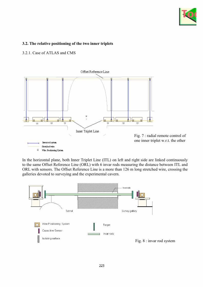
3.2. The relative positioning of the two inner triplets
3.2.1. Case of ATLAS and CMS
In the horizontal plane, both Inner Triplet Line (ITL) on left and right side are linked continuously
to the same Offset Reference Line (ORL) with 6 invar rods measuring the distance between ITL and
ORL with sensors. The Offset Reference Line is a more than 126 m long stretched wire, crossing the
galleries devoted to surveying and the experimental cavern.
Fig. 8 : invar rod system
Fig. 7 : radial remote control of
one inner triplet w.r.t. the other

Invar rods are equipped at their end with sensor targets. Thanks to capacitive sensors fixed to the
Wire Positioning sensors, the distance between both wires (ITL and ORL) is known continuously.
Temperature probes located along the invar rod allow dilatation corrections.
In the vertical plane, a hydrostatic network crossing the galleries reserved for surveying and the
experiment cavern links the two networks installed on each inner triplet.
Due to the sloping LHC tunnel, we use a “HLS reach” as shown in the figure below to link one side
of the tunnel to the other.
Fig. 9 : vertical remote control
of one inner triplet w.r.t. the
other
Fig. 10 : “HLS reach”

3.2.2. Case of ALICE and LHCb
After the completion of the installation of the experiment, no direct connection in X and Y is
possible between left and right tunnels around IP2 and IP8, as no dedicated gallery exists. Only the
relative position of the 3 quadrupoles of a same triplet is controlled in X and Y.
So there is a remote control of one inner triplet with respect to the other only vertically with the
Hydrostatic Leveling System.
3.3. Electronic system for the low beta alignment maintenance “beam on”
4. TAP FACILITY
In order to study and optimize the configuration of the sensors and jacks that will be used, a facility
named TAP has been implemented.
Fig. 11 : electronic system

4.1. Presentation
The TAP facility is a cryomagnet prototype similar to the quadrupole Q2, which has been equipped
with 4 alignment targets.
The TAP facility is equipped with Hydrostatic Leveling System (HLS) linked by two hydraulic
networks (two pipes with air and water separated, one pipe half filled), biaxial Wire Positioning
System (WPS2) and one inclinometer. Three polyurethane jacks have been installed under the
magnet in order to study and compare the servo positioning using the different sensors.
Picture 1 : TAP
Fig. 12 : TAP configuration

The objectives of the TAP facility are the following:
- To qualify servo positioning system according to data taken from Hydrostatic Leveling
System or Wire Positioning System coupled with one inclinometer
- To determine the type of hydraulic network to use for servo positioning: there are 2
possibilities: one tube half filled with water or two tubes separated for water and air.
- To prepare the technical specifications regarding alignment systems
- To choose the equipments (valves, hydraulic tubes,…) on which irradiations tests will be
performed.
4.2. First results
4.2.1. Comparison between the two types of hydraulic networks
The same motorized displacement of a jack at point 3 of the TAP has been observed by both HLS
belonging to the following hydraulic network:
- first case: half filled pipe with water
- second case: two separated pipes for water and air
Picture 2 : HLS linked by two hydraulic networks Picture 3 : motorized polyurethane jacks
Fig. 13 : Vertical displacement seen by HLS belonging to different hydraulic networks

The displacement is made by stepping motor.
As far as the lever arm effects are concerned, the displacement of the jack under point3 has no effect
on the HLS sensors located on points 1 and 4. The difference between HLS1 and HLS4 stays
constant, except some disturbances of the water reference surface during the displacements of the
jacks, which are greater for one pipe hydraulic network.
Both curves (hls1-hls3) and (hls3-hls4) are symmetric (see fig.13). They show the displacement of
point 3 with respect to point 1 and point 4 considered as reference.
The stabilization time of hydraulic network is much greater concerning the one pipe network: the
displacement of the jack under point 3 induces some waves.
4.2.2. Servo positioning seen by the two types of hydraulic networks
Thanks to the two WPS2 and one inclinometer, the TAP magnet is servo positioned according to 5
degrees of freedom. Reference values for both WPS2 and inclinometer are registered. When the
calculated offset between the reference values and the actual values becomes too great, the magnet is
adjusted with the jacks until the new values are acceptable. In order to generate perturbations on the
servo positioning, some lead bricks can be installed on the TAP magnet.
As shown on figure 13, one pipe hydraulic network is more sensitive to displacements and needs a
longer stabilization time. Readings coming from HLS sensors belonging to one pipe network cannot
be used for servo positioning.
4.2.3. Stability of the measurements
The following graph shows HLS readings made during 15 days, with respect to the mean level:
- (HLS1_B) is linked to the two separated pipes network
- (HLS1_H) is linked to the half filled water pipe network.
The standard deviation between both measurements is less than 0.3 µm during the 15 days.
Fig. 14: perturbation of servo positioning: influence on HLS readings

5. CONCLUSION
The configuration of sensors for the alignment “beam on” of the low beta quadrupoles has been
determined. Regarding HLS hydraulic network, one half filled pipe network will link both sides of
experimental area : this HLS system is meant for long term stability measurements, see [6] fig. 13
showing measurements obtained on the same type of network. A two separated pipes network will
link HLS sensors located on the quadrupoles and will be used for remote positioning. The
integration of all these alignment systems in official layouts of the tunnel and have the experiment
areas is under way, as well as the preparation of the installation. The first jacks will be installed in
the tunnel at the end of 2004.
6. REFERENCES
[1] J-P. Quesnel, Alignment of the inner triplets, LHCIR alignment workshop at Fermilab, 4-5 october 99
[2] J-P. Quesnel, The alignment of LHC: review of metrological aspects, IWAA97, Argonne, 1997[3] D. Missiaen, ,3-D metrology applied to superconducting dipoles magnets for LHC, IWAA99, ESRF,
[4] W. Coosemans, A. Marin, K. Rybaltchenko, F. Tecker, J. Wenninger, Closed orbit feed-back from low-beta
quadrupole movements at LEP, CERN, Geneva, Switzerland
[5] W. Coosemans, H. Mainaud, Pre-alignment of CLIC using the double-wire method., IWAA97, Argonne,
Chicago, 1997
[6] F. Becker, W. Coosemans, M. Jones, Consequences of perturbations of the gravity field on HLS measurements,IWAA02, Spring8, Japan, 2002.
Fig. 15 : stability of the
HLS measurements