The Actuated Workbench: 2D Actuation in Tabletop Tangible Interfaces
108
The Actuated Workbench: 2D Actuation in Tabletop Tangible Interfaces Gian Antonio Pangaro B.A. Sociology 1999 Harvard University Submitted to the Department of Media Arts and Sciences, School of Architecture and Planning, in partial fulfillment of the requirements for the degree of Master of Science in Media Arts and Sciences at the Massachusetts Institute of Technology September 2003 Massachusetts Institute of Technology, 2003. All Rights Reserved. Author Gian Pangaro Program in Media Arts and Sciences 09 May 2003 Certified by Hiroshi Ishii Associate Professor of Media Arts and Sciences Thesis Supervisor Accepted by Andy Lippman Chair, Departmental Committee on Graduate Studies Program in Media Arts and Sciences
Transcript of The Actuated Workbench: 2D Actuation in Tabletop Tangible Interfaces

The Actuated Workbench: 2D Actuation in Tabletop Tangible Interfaces
Gian Antonio Pangaro
B.A. Sociology 1999
Harvard University
Submitted to the Department of Media Arts and Sciences,
School of Architecture and Planning,
in partial fulfillment of the requirements for the degree of
Master of Science in Media Arts and Sciences at the
Massachusetts Institute of Technology
September 2003
Massachusetts Institute of Technology, 2003.
All Rights Reserved.
Author
Gian PangaroProgram in Media Arts and Sciences
09 May 2003
Certified by
Hiroshi IshiiAssociate Professor of Media Arts and Sciences
Thesis Supervisor
Accepted by
Andy LippmanChair, Departmental Committee on Graduate Studies
Program in Media Arts and Sciences

2

3
The Actuated Workbench: 2D Actuation in Tabletop Tangible Interfaces
Gian Antonio Pangaro
B.A. Sociology
Harvard University 1999
Submitted to the Department of Media Arts and Sciences,
School of Architecture and Planning,
in partial fulfillment of the requirements for the degree of
Master of Science in Media Arts and Sciences at the
Massachusetts Institute of Technology
September 2003
Abstract
The Actuated Workbench is a new actuation mechanism thatuses magnetic forces to control the two-dimensional move-ment of physical objects on flat surfaces. This mechanism isintended for use with existing tabletop Tangible User Inter-faces, providing computer-controlled movement of the physi-cal objects on the table, and creating an additional feedbacklayer for Human Computer Interaction (HCI). Use of this actu-ation technique makes possible new kinds of physical inter-actions with tabletop interfaces, and allows the computer tomaintain consistency between the physical and digital statesof data objects in the interface. This thesis focuses on thedesign and implementation of the actuation mechanism as anenabling technology, introduces new techniques for motioncontrol, and discusses practical and theoretical implicationsof computer-controlled movement of physical objects in table-top tangible interfaces.
Thesis Supervisor: Hiroshi IshiiTitle: Associate Professor of Media Arts and Sciences

4

5
The Actuated Workbench: 2D Actuation in Tabletop Tangible Interfaces
Gian Antonio Pangaro
Thesis Comittee:
Thesis Supervisor
Hiroshi IshiiAssociate Professor of Media Arts and Sciences
MIT Media Lab
Thesis Reader
Robert JacobAssociate Professor of Electrical Engineering and Computer Science
Tufts University
Thesis Reader
Joe ParadisoAssociate Professor of Media Arts and Sciences
MIT Media Lab

6

7
Acknowledgements
I am forever grateful to the following people for being in my lifeduring the past few years. Without them, this work might not havebeen possible.
For their love and support:
Stacy AbderAnthony PangaroGeraldine Pangaro
For their intellectual guidance, enthusiasm, and inspiration:
Jason AlonsoDan ChakChris CsikszentmihalyiRich FletcherHiroshi IshiiRob JacobJohn MaedaDan Maynes-AminzadeJoe ParadisoAmanda ParkesJames PattenHayes RaffleNancy SunBrygg UllmerBill Verplank
For their friendship, music, and good advice:
John CapelloAndy EggersScott RoyAltay GuvenchMike Annanydanah boydDaneil GiffinShane HamiltonSaoirse HigginsRyan McKinleyCliff MurphyMary OeyPhua Mei PinAli RahimiLily ShirvaneeDoug SwettJessica TardyNoam WeinsteinPierce Woodward

88

9
Table Of Contents
Prefatory MaterialCoverAbstractThesis CommitteeAcknowledgements
1. Introduction 111.1 Tabletop Tangible Interfaces 1.2 Thesis Goal
2. Theory: Space, Movement, and Haptics for Input Devices 153. Related Technologies 1: Tabletop Tracking Technologies 204. TUI Inconsistency and Input Device Design 24
4.1 TUI Interactions that can lead to Inconsistencies 4.2 Haptic Input Devices as Physical Output for Digital Media
5. Related Technologies 2: Tabletop Actuation Technologies 336. Design and Development 40
6.1 Design Criteria 6.2 Final Design Scheme
7. Technical Details 447.1 System Description 7.2 Motion Control and Interpolation
8. Evaluation 588.1 Original Design Criteria 8.2 Design Limitations 8.3 User Testing
9. Applications for the Actuated Workbench 649.1 Basic GUI Functions 9.2 High-Level Tabletop Interactions 9.3 Haptic applications
10. Future Development 7410.1 Tiling of Arrays for Larger Surfaces 10.2 New Types of Motion
11. Conclusion 78
Appendix A. Explanation of Electromagnetic Array 82
Appendix B. Limitations of SaJe microcontroller 85
Appendix C. Other Actuation Technologies 87
Appendix D. Schematics 89
Appendix E. Microcontroller Code 95
References 103

1010

11
1. Introduction
At the inception of the Tangible Interface realm of Human
Computer Interaction (HCI), a research vision called “Tangi-
ble Bits” [19] sought to leverage people’s existing skills for
interacting with the physical world toward improving their
interactions with computers. The stated research goal was to
extend computation beyond traditional Graphical User Inter-
faces (GUIs) to interfaces that use physical objects and the
physical world as tangible embodiments of digital information.
Such interfaces allow users direct control of computation
through the manipulation of physical objects. These stand in
contrast to the traditional Graphical User Interface, which
usually consists of a computer monitor (graphical display),
keyboard, and pointing device, such as a mouse or trackball.
Instead, Tangible User Interfaces (TUIs) aim to provide users
with means to directly manipulate electronic media by manip-
ulating physical objects that represent the data itself, rather
than pointers to it. The physical objects in tangible interfaces
can take on many forms. Some are simple knobs and levers,
while more advanced interfaces include physical models of
buildings [52] or lumps of clay [36]. As electronic sensing
technologies continue to advance, the possibilities continue
to grow for designing physical input devices for computers.
1.1 Tabletop Tangible Interfaces
Recent tangible interface research has given rise to a class of
systems based on physical interaction with interactive table-
top surfaces. These systems, which I will refer to as ‘tabletop
tangible interfaces’ (or ‘tabletop TUIs’ for short), track the
position and movement of objects on a flat surface and
respond to users’ physical manipulation of these objects with
graphical output. In most tabletop tangible interfaces, as the
user physically interacts with the system, graphical feedback
is usually projected on and around the objects on the table.
The objects are treated as physical instantiations of digital
data: users make adjustments to the digital state of a data
item by 1) moving (translating, rotating, etc.) or 2) modifying
Figure 1.1 An abacus, longtime iconof the Tangible Bits concept. Theabacus is an interface containing aphysical instantiation of every bit,and the physical state of the systemrepresents a logical state that can beboth seen and felt by the user..

12
the physical object (pressing a button on it, placing another
object on top of it, etc.). Both of these actions not only
change the object’s state relative to absolute X and Y posi-
tion on the table, but also in relation to other objects on the
table. The distance between physical objects is often mapped
to some aspect of data in the digital realm, and therefore the
user can easily tell relationships in the digital part of the inter-
face from the physical relationship of the objects.
Advantages of Tabletop Tangible Interfaces
Tabletop tangible interfaces offer many advantages over
interaction with purely graphical computer interfaces. Users
can organize objects spatially in the physical area around
them, providing a kinesthetic sense of the location of each
data item [34]. Tabletop interfaces allow users to perform
two-handed interactions with data, making it possible to
adjust several different parameters of a simulation or applica-
tion simultaneously. These interfaces also foster ease of col-
laboration between multiple collocated users, since the work
area is expanded from a small computer monitor to a large
tabletop area. Since there is no need for an intermediary tool
or pointing device, such as a mouse, any user around the
table can reach out and adjust parameters in the application
simply by moving associated physical objects.
Limitations of Current Tabletop Tangible Interfaces
Current tabletop tangible interface systems share a common
weakness. While users provide input by manipulating of
physical objects, computer output occurs only through sound
or graphical projection. This discrepancy between input and
output can make the objects feel more like pointers to digital
data and less like physical manifestations of the data itself.
Links between physical objects and digital data can also
break down when changes occur in the underlying computa-
tion that are not reflected in physical changes of associated
objects on the table. Since the computer system cannot
physically move objects on the table surface, the computer
cannot correct physical inconsistencies in the layouts of the
objects, and such corrections are left to the user. In addition,
tabletop tangible interfaces cannot provide users with physi-

13
cal versions of functionality commonly found in graphical user
interfaces. Only graphically can the computer system
express common interactive functions such as 1) undoing
physical input, 2) saving and restoring physical positions of
objects in a simulation, or 3) guiding users in manipulation of
objects. Most tabletop tangible interfaces respond to users’
physical input with output that is not physical, such as sound,
light, or graphical displays. For these tangible interfaces,
physical interaction between human and computer remains
one-directional.
1.2 Thesis Goal
This thesis describes the design and development of the
Actuated Workbench, a system that provides a hardware and
software infrastructure for a computer to move objects hori-
zontally on a table surface. The mechanism for moving
objects on the table is a technological innovation using elec-
tromagnetic forces to move objects in the manner of a linear
induction motor (LIM) expanded to two dimensions. As a
Research Assistant in the Tangible Media Group at the MIT
Media Lab, I developed this actuation system for use with
pre-existing tabletop tangible interfaces, providing a general
actuation platform for moving objects in two dimensions.
Actuation can be defined as:
1. A bringing into action; movement [Webster's RevisedUnabridged Dictionary, © 1996, 1998 MICRA, Inc]
2. the act of propelling [WordNet ® 1.6, © 1997 Prince-ton University]
In this thesis, I use the term ‘actuation’ to describe the two-
dimensional movement of objects on a flat surface. The
attraction and repulsion of an electromagnetic array propels
magnetic objects on top of a tabletop tangible interface,
allowing both the user and computer to move the objects for
physical interaction.
The Actuated Workbench represents one attempt to “close
the loop” in the interactive tabletop realm of tangible inter-
Figure 1.2 Traditional Tabletop Tangi-ble Interfaces track multiple objectson a tabletop and respond to user’sphysical input with graphical outputfrom projection overhead.
Figure 1.3 The Actuated Workbenchuses magnetic movement of objectson the table as an additional layer offeedback between the computer andthe user.

14
faces, matching physical input with physical output. It is one
of only a few projects in tangible interfaces research that
attempt to match physical input with physical output [7, 16,
45]. In this thesis, I will situate the system in the context of
past related work and supporting theory, discuss some theo-
retical implications of actuation in tangible interface design,
discuss the variety of hardware and software design deci-
sions involved in its construction, describe the underlying
technology of the Actuated Workbench and evaluate its per-
formance in light of my design criteria, and finally suggest
preliminary applications of this actuation technology. Several
of these applications were implemented in collaboration with
Dan Maynes-Aminzade, another research assistant in the
Tangible Media Group. The Actuated Workbench was devel-
oped under the guidance of my advisor, Professor Hiroshi
Ishii. The term “we” in this thesis refers to myself, Dan May-
nes-Aminzade, and Professor Hiroshi Ishii, as this was truly a
collaborative project throughout most of its design and devel-
opment.

15
2. Theory: Space, Movement, and Haptics for Input Devices
Tangible User Interface design finds support in early HCI
research and psychological studies of kinetics and spatial
reasoning. This section discusses work that has been used in
the past as supporting arguments for advantages of both
graphical interfaces and tangible interfaces. Much of this
work has been discussed at length in other publications
related to Tangible User Interfaces (TUIs) as well as tabletop
TUIs. Since this thesis is primarily about actuation in Table-
top TUIs, its agenda already assumes the benefits of tabletop
TUIs as input devices. Therefore, I will not go into great detail
discussing this work. Extensive discussion of these and other
supporting works can be found in: Fitzmaurice’s Ph.D. Thesis
[13], Ishii and Ullmer’s Tangible Bits paper [19], and Patten’s
MS thesis [34]. However, since much of this work also has
implications supporting actuated tabletop TUI, I will touch on
some key supporting concepts of this work and discuss how
they can be used to argue the benefits of actuated TUI.
Manipulation: GUI to Graspable UI to TUI
Since 1986, the concept of Direct Manipulation [17] has been
at the core of both Graphical and Tangible User Interface
research. Much published research has demonstrated how
tabletop tangible interface design furthers the cause of direct
manipulation, providing 1) “a continuous representation of the
object of interest,” 2) commands effected through physical
action rather than complex syntax, and 3) “rapid incremental
reversible operations whose impact on the object of interest
is immediately visible” [43,44]. In his 1996 thesis on grasp-
able user interfaces, Fitzmaurice argues that “improving the
‘directness’ and the ‘manipulability’ of the interface can be
achieved by improving the input mechanisms for graphical
user interfaces” [13]. He goes on to show how the Bricks
interface furthers the cause of direct manipulation by provid-
ing users a more physical means of interacting with computer
graphics through graspable handles.

16
Since that publication, tabletop tangible interfaces have fur-
ther improved the “directness” of manipulation by integrating
physical input in the same space as graphical output, often
projecting directly onto the objects themselves. This implies
to users that they are manipulating physical manifestations of
digital data itself, not just physical handles to digital graphics.
Kirsh: The Intelligent Use of Space
Kirsh’s research on people’s use of physical space shows
that the use of physical objects and spatial organization can
reduce cognitive load in task performance. Kirsch’s experi-
ments [24, 25] have shown that subjects who were provided
with a means of physically offloading a computational task
onto physical objects in front of them were able to perform
tasks (such as counting coins) with improved completion
times and reduced error rates. Experiments conducted else-
where involve similar tasks such as sorting small LEGO parts
by color [13] (Figure 2.1). What is interesting is the number of
these experiments that note improved performance results in
conditions involving the use of multiple hand-sized objects
resting on tabletops. These results suggest that a computer
interface using objects on a tabletop would provide similar
reductions in cognitive load and increased performance.
A prime example of such results is an experiment conducted
by James Patten during his preliminary work on the
Sensetable project [35]. The experiment measured subjects’
performance in a memory task, comparing the use of graphi-
cal objects, displayed on a screen and manipulated by a
mouse, with the use of electronically tagged physical objects.
He found that subjects who adopted specific strategies
involving the spatial layout of objects performed better on the
memory recall task. Patten attributes some of these results to
subjects’ ability to use their bodies as references to the posi-
tions of individual objects. From this and other observations,
he speculates that the objects people use for such tasks must
be large enough to prompt a visceral association with users,
yet small enough that many objects can be laid out within
arms reach for easily manipulation by a single user.
Figure 2.1 A subject performing aLEGO sorting task in a study on peo-ple’s use of spatial arrangement andtwo-handed manipulation.

17
Input Devices: Time Multiplexing vs. Space Multiplexing
Fitzmaurice and Buxton have created a taxonomy of input
devices for computer functions. Since there are often many
different logical functions that can be performed in a com-
puter application, user input must be multiplexed between
these functions. Buxton and Fitzmaurice describe input
devices as either “time-multiplexing” or “space-multiplexing”
[14]. With a traditional mouse and keyboard GUI, the mouse
is time-multiplexed between logical functions, meaning that
the user repeatedly attaches and detaches the mouse to on-
screen tools in order to perform different functions. For exam-
ple, to switch between a pencil tool and an eraser tool in a
GUI drawing program, the user clicks with the mouse on
either tool to attach the logical function to the mouse pointer,
and then proceeds to use that new function. The keyboard,
on the other hand, is space-multiplexed for the input of char-
acters to the computer, providing a discrete physical location
for each letter of the alphabet as well as other commands.
This layout makes touch-typing possible, as the user can
remember the persistent location of each letter and can learn
to access each letter quite quickly using muscle memory. TUI
allows several physical input devices to be simultaneously
attached to logical functions, allowing users to access differ-
ent tools simply by grabbing different physical objects in front
of them. TUI input devices are said to be space-multiplexed
because they are persistently bound to logical functions and
the user’s input is swapped between physical devices. Fitz-
maurice and Buxton argue that space-multiplexed input
devices have fewer stages of acquisition before interaction,
allowing faster computer input from the user (Figure 2.3).
Snibbe et al. also argue that systems having multiple
“modes” for input devices (time-multiplexed input) require
that the user keep track of the mode in which the input device
was last used, and whether that device’s mode must be
switched to a new mode before it can be used for another
task [47]. Such mode switching increases workload and user
error, since the user is charged with the task of monitoring
both the physical and digital state of the input device. Snibbe
et al. argue for removing as much mode-switching from input
Figure 2.2 According to Buxton andFitzmaurice’s taxonomy, the mouse(top) is a time-multiplexed inputdevice, while the mixing board (bot-tom) is a space-multiplexed inputdevice.
GUI (Time-Multiplexed)
1. Acquire physical device2. Acquire logical device3. Manipulate logical device
TUI (Space-Multiplexed)
1. Acquire physical device2. Manipulate logical device
Figure 2.3 Fitzmaurice and Buxton’sacquisition stages for interactionwith logical devices. The space mul-tiplexed condition contains onefewer phases of preparatory actionfor manipulating logical devices.
18
devices as possible, saying that modeless interaction pro-
vides the user with a “consistent and trustworthy physical
behavior, like that of a car steering wheel.” In modeless inter-
action, the behavior of a particular input device is predictable,
and the user can take advantage of this predictability by
anticipating how the device will react given a certain input.
Space-multiplexed input devices exhibit modeless interaction
through persistent mappings to logical functions and through
their consistent physical behavior.
Fitzmaurice and Buxton conducted an experiment comparing
space-multiplexed input devices with time-multiplexed input
devices in an on-screen target tracking task [14]. They found
that subjects performed the task with less error (i.e. more
accurate and constant tracking) in the space-multiplexed
condition than in the time-multiplexed condition. They also
noted that in the time-multiplexed condition, subjects spent
almost 50% of device manipulation time acquiring new logical
functions for the input device, indicating the large cost of
switching the function of the input device. Their results sug-
gest that computer interfaces consisting of multiple, space-
multiplexed input devices on a tabletop offer significant time
and error improvements over time-multiplexed input devices
such as a mouse.
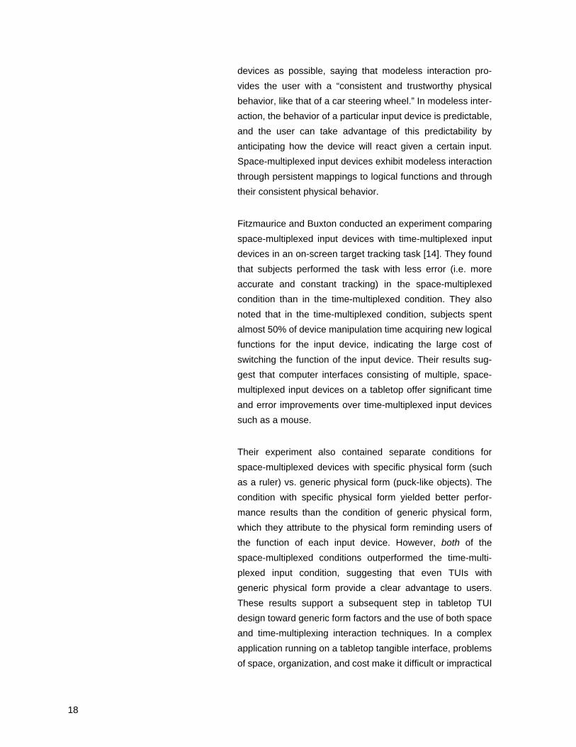
Their experiment also contained separate conditions for
space-multiplexed devices with specific physical form (such
as a ruler) vs. generic physical form (puck-like objects). The
condition with specific physical form yielded better perfor-
mance results than the condition of generic physical form,
which they attribute to the physical form reminding users of
the function of each input device. However, both of the
space-multiplexed conditions outperformed the time-multi-
plexed input condition, suggesting that even TUIs with
generic physical form provide a clear advantage to users.
These results support a subsequent step in tabletop TUI
design toward generic form factors and the use of both space
and time-multiplexing interaction techniques. In a complex
application running on a tabletop tangible interface, problems
of space, organization, and cost make it difficult or impractical
19
to have a devoted physical input device for every logical func-
tion available in a computer application. Tabletop TUIs involv-
ing objects with generic physical form, such as Sensetable,
can offer a combination of both space-multiplexing and time-
multiplexing input techniques. The Sensetable system tracks
multiple, space-multiplexed physical input devices, built with
a generic shape that indicates little about a device’s logical
function. Devices can be dynamically attached and detached
to logical functions, and the functions or parameters to which
devices are attached are indicated by projection on and
around the objects. Users can use these devices in a space-
multiplexed-only scenario, or if they desire fewer objects on
the table (to reduce clutter, for example), they can use the
objects as time-multiplexed input devices.
These and other arguments have been made supporting the
development of tabletop TUIs and their progression toward
the generic form factors commonly used today. The next sec-
tion describes past work in tabletop tangible interfaces, and
the development of interaction techniques using physical
objects.
20
3. Related Technologies 1: Tabletop Tracking Technologies
One cannot discuss the evolution of interactive tabletop inter-
faces without charting the evolution of technologies associ-
ated with them. In this chapter I describe various techniques
used in tabletop systems to track objects on flat surfaces, the
types of interactions afforded by such technologies at the
time, and the limitations inherent in the tracking technologies.
Many of the interaction techniques developed in these sys-
tems inspired as many questions as they did answers, and I
will mention some of these questions as they arise.
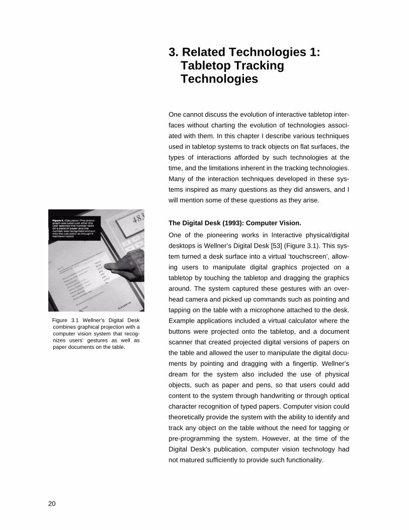
The Digital Desk (1993): Computer Vision.
One of the pioneering works in Interactive physical/digital
desktops is Wellner’s Digital Desk [53] (Figure 3.1). This sys-
tem turned a desk surface into a virtual ‘touchscreen’, allow-
ing users to manipulate digital graphics projected on a
tabletop by touching the tabletop and dragging the graphics
around. The system captured these gestures with an over-
head camera and picked up commands such as pointing and
tapping on the table with a microphone attached to the desk.
Example applications included a virtual calculator where the
buttons were projected onto the tabletop, and a document
scanner that created projected digital versions of papers on
the table and allowed the user to manipulate the digital docu-
ments by pointing and dragging with a fingertip. Wellner’s
dream for the system also included the use of physical
objects, such as paper and pens, so that users could add
content to the system through handwriting or through optical
character recognition of typed papers. Computer vision could
theoretically provide the system with the ability to identify and
track any object on the table without the need for tagging or
pre-programming the system. However, at the time of the
Digital Desk’s publication, computer vision technology had
not matured sufficiently to provide such functionality.
Figure 3.1 Wellner’s Digital Deskcombines graphical projection with acomputer vision system that recog-nizes users’ gestures as well aspaper documents on the table.
21
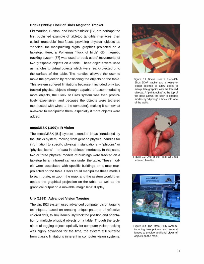
Bricks (1995): Flock of Birds Magnetic Tracker.
Fitzmaurice, Buxton, and Ishii’s “Bricks” [12] are perhaps the
first published example of tabletop tangible interfaces, then
called ‘graspable’ interfaces, providing physical objects as
‘handles’ for manipulating digital graphics projected on a
tabletop. Here, a Polhemus “flock of birds” 6D magnetic
tracking system [37] was used to track users’ movements of
two graspable objects on a table. These objects were used
as handles to virtual objects which were rear-projected onto
the surface of the table. The handles allowed the user to
move the projection by repositioning the objects on the table.
This system suffered limitations because it included only two
tracked physical objects (though capable of accommodating
more objects, the Flock of Birds system was then prohibi-
tively expensive), and because the objects were tethered
(connected with wires to the computer), making it somewhat
awkward to manipulate them, especially if more objects were
added.
metaDESK (1997): IR Vision
The metaDESK [51] system extended ideas introduced by
the Bricks system, moving from generic physical handles for
information to specific physical instantiations -- “phicons” or
“physical icons” -- of data in tabletop interfaces. In this case,
two or three physical models of buildings were tracked on a
tabletop by an infrared camera under the table. These mod-
els were associated with specific buildings on a map rear-
projected on the table. Users could manipulate these models
to pan, rotate, or zoom the map, and the system would then
update the graphical projection on the table, as well as the
graphical output on a movable ‘magic lens’ display.
Urp (1999): Advanced Vision Tagging
The Urp [52] system used advanced computer vision tagging
techniques, based on creating unique patterns of reflective
colored dots, to simultaneously track the position and orienta-
tion of multiple physical objects on a table. Though the tech-
nique of tagging objects optically for computer vision tracking
was highly advanced for the time, the system still suffered
from classic limitations inherent in computer vision systems,
Figure 3.2 Bricks uses a Flock-Of-Birds 6DoF tracker and a rear-pro-jected desktop to allow users tomanipulate graphics with the trackedobjects. A “paintbucket” at the top ofthe desk allows the user to changemodes by “dipping” a brick into oneof the wells.
Figure 3.3 One of the Flock-Of-Birdstethered handles.
Figure 3.4 The MetaDESK system,including two phicons and severallenses to provide additional views ofobjects on the map.

22
such as slow tracking speed, jitter, large size of objects (lim-
ited by the size of the reflective dots) and occlusion by users’
hands.
Sensetable (2001): Electromagnetic Tagging
Sensetable 1.0: Wacom Tablets
The advent of commercial electromagnetic tracking technolo-
gies provided new levels of functionality and robustness for
tabletop interfaces. James Patten’s MS thesis, Sensetable,
was one of the first systems to take advantage of these tech-
nologies and bring new levels of flexibility to tabletop tangible
interfaces. The first Sensetable system used Wacom Intu-
osTM tablets and hacked versions of wireless Wacom com-
puter mice as the technology built into “pucks” on the
tabletop. The Wacom system, then state of the art, provided
high-precision, extremely fast tracking of two objects on one
tablet. Sensetable’s designers (at the time, Patten and I)
added circuitry to the mice that allowed the system to track
twice as many objects with only slightly increased latency.
Since the system used radio frequency signals transmitted
inductively between the pucks and antennas in the tablet, it
suffered none of the stability problems present in computer
vision systems. This fast and robust tracking provided the
ability to introduce interactions based on users’ real-time ges-
tures with pucks on the table. In addition to speed, accuracy,
and robustness improvements, the Wacom system provided
sensing for rotation of the puck, three separate button
presses and the manipulation of a potentiometer (a dial on
top of each puck). Sensetable’s designers used this addi-
tional functionality to develop new interaction techniques,
such as the use of physical modifiers (tokens) that could be
added to the pucks to change their state, and the inclusion of
dials on top of the pucks that allowed users to manipulate
variables associated with the pucks.
Sensetable 1.5: Zowie
In 2000, Zowie Intertainment™, which later became part of
the LEGO Group, developed a new multi-object tracking
technology licensed from a patent held by the Scientific
Generics corporation [15]. This technology was developed
Figure 3.5 The Urp system usesvi-sion tracking and special reflectorsto locate models of buildings on thetable. A digital shadow of the build-ing is then projected around themodel.
Figure 3.6 Sensetable 1.0. WacomIntuos Wireless Mice were usedinside the pucks, with dials on topthat could be used to manipulatevariables associated with eachparameter in the application.

23
and cost-reduced enough that it could be built into an afford-
able toy playset for use with a PC to play interactive games.
The playset consisted of movable figurines on a flat plastic
surface, which children could move and view interactive
graphics on a computer monitor. The tracking technology
included passive tags made of LC “tank” circuits, and a flexi-
ble antenna array built into the flat surface of the playset. The
system measures the amplitude of the tag resonances with
several specially shaped antennas. The amplitude of the
tag's resonance with each antenna varies as a function of its
position on top of the antenna array. This method gives very
stable 2D position data, accurate to within 2 millimeters, of up
to nine different tags at refresh rates of up to 10 milliseconds.
Since each tag on the table resonates at a different fre-
quency, their positions can be determined independently.
Unlike the Wacom tablet system, Zowie technology is not
capable of sensing rotation of these tags. This tracking tech-
nology was later modified and used by Patten in final proto-
types of the Sensetable 1.5 system. Puck rotation was
sensed using two LC tags at opposite ends of a puck.
Sensetable 2: Capacitive Sensing
Also included in development plans for the Sensetable sys-
tem was the design of a new custom tracking platform based
on capacitive transfer of radio frequency signals between
pucks and the table. This system would provide a hardware
infrastructure for tracking as many objects as could fit on the
table, and for sensing up to five modifiers and three analog
input devices, such as dials, as well as capacitively sensing
users’ touch. A prototype of this system was designed by
Media Lab graduate Matt Reynolds in the fall of 2000, but
was never fully implemented by Patten and myself due to the
superior flexibility of the Zowie-based tracking technology.
Figure 3.7 The Ellie’s Enchanted Gar-den playset, which contains theZowie tracking technology used inthe Sensetable 1.5 system.
Figure 3.8 A Zowie LC radio fre-quency tag. US Quarter shown forsize.
Figure 3.9 Sensetable 2.0 capacitivesensing board, designed by MattReynolds.

24
4. TUI Inconsistency and Input Device Design
This chapter describes common problems of consistency
among tangible interfaces, especially among the tabletop
TUIs described above. As a user interacts with a tabletop tan-
gible interface, there are many ways inconsistencies between
physical and digital states can arise. Previously, designers
have had to design interfaces so that as few of these incon-
sistencies arise as possible. The long term goals that inspired
this thesis project include a vision for seamless bi-directional
interaction with physical objects, which might involve the cre-
ation of completely new interaction techniques. However, the
problem of consistency alone has long called for an actuation
technology to address these problems in existing tabletop
interfaces. In this chapter, I discuss specific examples of
such design techniques and introduce new approaches to
resolving inconsistencies through actuation.
4.1 TUI Interactions that can lead toInconsistencies
Remote Collaboration
Tangible interfaces have been used in research on remote
collaboration and Community Supported Collaborative Work
(CSCW) for years [52, 26], but the technical challenge of syn-
chronizing remote physical objects has limited the usefulness
of such interfaces in spatially distributed applications. For
remote collaboration applications of tabletop TUIs, when
there are multiple instantiations of a work table, the physical
states of objects on the tables can become inconsistent
whenever a user moves an object on one table, but the
remote user does not move the corresponding object on the
other table. Though the graphical projections on top of the
tables can be synchronized, discrepancies between the posi-
tions of the multiple sets of physical objects on the tables
make it difficult to determine which is the “correct” version to
be projected on all workbenches. Even if the system could

25
determine a correct version and project it on the table, users
would still have to manually move the objects to the correct
positions. Furthermore, the fact that objects can be even tem-
porarily in positions that disagree with corresponding graphi-
cal projections tends to break the metaphor that they are in
fact two instantiations of the same data item, and the user
must mentally accommodate this inconsistency.
Parametric Simulation
A software simulation running in real-time may compute that
the digital value associated with a puck on the table has
changed. The puck's position or orientation may be inconsis-
tent with the new value of its corresponding software parame-
ter. This can happen if the puck represents a variable
dependent on another variable that is adjusted by the user.
Without actuation, the computer can only attempt to maintain
consistency through graphical projection, either changing the
projection to display the change, or perhaps prompting the
user to correct this problem by changing the physical state of
the object until it is consistent with the digital state.
Constraints
An application may contain pre-programmed constraints on
the spatial arrangement of objects on the table, such as zon-
ing laws that apply to the placement of buildings in an urban
planning application. Constraints in the simulation can
improve functionality in an application, helping to make sure
the simulated layout is actually possible in the real world. If
the user moves an object to the wrong part of the table, some
of these constraints may be violated. Existing systems can
provide graphical feedback to let the user know a constraint
has been violated, but cannot fix the problem for the user in
both the digital and physical representations. Giving the com-
puter the ability to physically move the objects on the table
can correct the problem once it has occurred, moving the
physical object to a new position that does not violate the
constraint. In addition, the use of force feedback can help
guide the user away from violating constraints in the first
place. If an actuation mechanism has enough force, it could
physically inhibit users from moving objects to the wrong

26
place on the table, but even if the system is not strong
enough to physically fight a user’s movement of an object, it
could still draw users’ attention to the violated constraint by
lightly tugging on the object, or by making it vibrate in the
user’s hand. In the case of tabletop TUIs, haptic feedback
can be more effective than graphical feedback because the
user may be looking elsewhere on the table and not at the
object in hand, or because the graphical projection may be
occluded by the user’s hand grasping the object.
Navigation
On tabletop tangible interfaces, applications with graphical
navigation features, such as those using a map [51], have
introduced fluid interaction techniques based on the rotation,
translation, or scaling of the map by moving physical objects
on top of it. For example, physical objects on the table, such
as models of a buildings, can be permanently associated with
specific positions on the map. A user can move one of the
models, and the map displayed on the table changes to fol-
low the user’s rotation or translation of the model.
In the design of the MetaDesk system, such map manipula-
tion techniques introduced the question of what happens
when there are multiple models of buildings on the same map
and a user moves only one model to change the map view.
With several models associated with positions of the map,
and the displayed map changing to follow the movement of
only one model, the physical position of other models on the
table will no longer be correct on the new map. In the case of
only two models, MetaDESK’s designers chose to “ignore the
offending rotation,” but did not provide a scheme for deter-
mining which was the correct or intended rotation. They spec-
ulated as to whether the map should be warped to
accommodate all rotations of the models, but felt that such a
display might not make sense or be useful to the user. More-
over, it becomes even more difficult to resort to such a solu-
tion when more than two physical objects are used in the
interface. Other solutions suggested by MetaDESK’s design-
ers include: 1) accommodating as many of the physical posi-
tions of objects on the table as possible while ignoring and
27
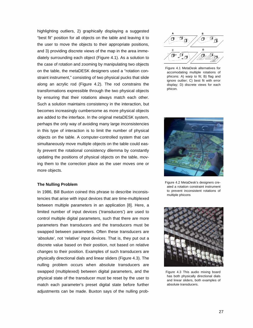
highlighting outliers, 2) graphically displaying a suggested
“best fit” position for all objects on the table and leaving it to
the user to move the objects to their appropriate positions,
and 3) providing discrete views of the map in the area imme-
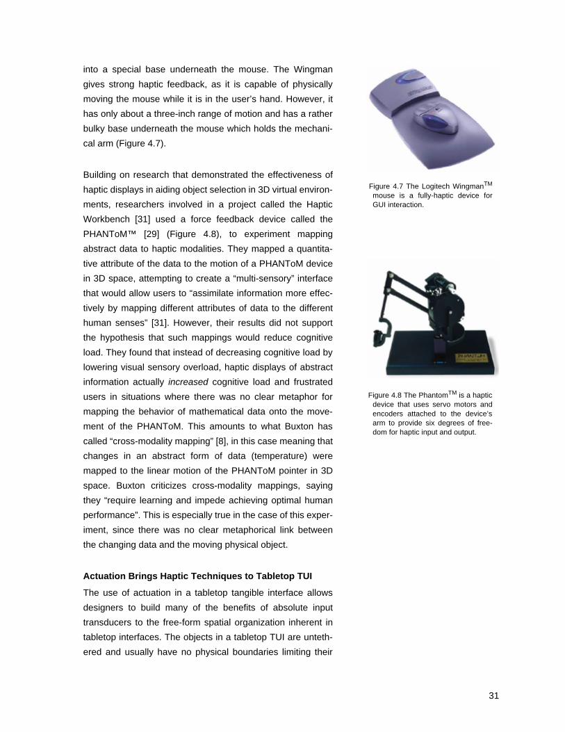
diately surrounding each object (Figure 4.1). As a solution to
the case of rotation and zooming by manipulating two objects
on the table, the metaDESK designers used a “rotation con-
straint instrument,” consisting of two physical pucks that slide
along an acrylic rod (Figure 4.2). The rod constrains the
transformations expressible through the two physical objects
by ensuring that their rotations always match each other.
Such a solution maintains consistency in the interaction, but
becomes increasingly cumbersome as more physical objects
are added to the interface. In the original metaDESK system,
perhaps the only way of avoiding many large inconsistencies
in this type of interaction is to limit the number of physical
objects on the table. A computer-controlled system that can
simultaneously move multiple objects on the table could eas-
ily prevent the rotational consistency dilemma by constantly
updating the positions of physical objects on the table, mov-
ing them to the correction place as the user moves one or
more objects.
The Nulling Problem
In 1986, Bill Buxton coined this phrase to describe inconsis-
tencies that arise with input devices that are time-multiplexed
between multiple parameters in an application [8]. Here, a
limited number of input devices (‘transducers’) are used to
control multiple digital parameters, such that there are more
parameters than transducers and the transducers must be
swapped between parameters. Often these transducers are
‘absolute’, not ‘relative’ input devices. That is, they put out a
discrete value based on their position, not based on relative
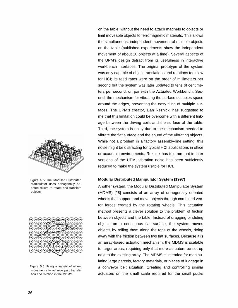
changes to their position. Examples of such transducers are
physically directional dials and linear sliders (Figure 4.3). The
nulling problem occurs when absolute transducers are
swapped (multiplexed) between digital parameters, and the
physical state of the transducer must be reset by the user to
match each parameter’s preset digital state before further
adjustments can be made. Buxton says of the nulling prob-
Figure 4.1 MetaDesk alternatives foraccomodating multiple rotations ofphicons: A) warp to fit; B) flag andignore outlier; C) best fit with errordisplay; D) discrete views for eachphicon.
Figure 4.2 MetaDesk’s designers cre-ated a rotation constraint instrumentto prevent inconsistent rotations ofmultiple phicons
Figure 4.3 This audio mixing boardhas both physically directional dialsand linear sliders, both examples ofabsolute transducers.

28
lem: “It is common, takes time to carry out, time to learn, and
is a common source of error. Most importantly, it can be
totally eliminated if we simply choose a different transducer.”
In his master’s thesis, Patten encountered a nulling problem
in the first prototype of the Sensetable system [34]. Here, as
pucks in the system were dynamically bound to different
parameters, dials on the pucks (Figure 4.4) would be in posi-
tions that did not correspond to the preset digital state of the
new parameters. Patten resolved this inconsistency by auto-
matically setting the digital value of the new parameter to the
current physical position of the dial on the puck. In his user
studies, Patten found that this practice confused and frus-
trated users, since the puck was “supposed to be a physically
manipulable representation of the data, rather than solely a
tool for changing simulation parameters.” Users wanted the
positions of the dials on the pucks to be automatically con-
trolled by the computer. In later versions of the Sensetable
system, Patten designed around this problem by using a per-
fectly round puck as the transducer and mapping relative
rotation of the puck to relative changes in the value of its
associated parameter. The user received feedback about the
current value of the parameter through projection of an arrow
or a slider bar next to the puck (Figure 4.5).
Buxton recommends avoiding the nulling problem in exactly
this way -- by choosing input devices whose physical posi-
tions do not correspond absolutely to specific numerical val-
ues, and instead whose relative motion (rotation, etc.)
corresponds to relative changes relative of the parameter’s
digital state. However, Buxton’s argument omits a discussion
of the benefits of absolute transducers. The fact that a slider
has a limited amount of travel, that a dial has a physical
pointer on it, that there are limits to the range and speed of
movement of an input device can be of great benefit to inter-
action. Absolute positioning in input devices provides users
with a kinesthetic sense of the current and last input states of
the device, as its digital state is a physically persistent quality
of the device. Designers such as Snibbe et al. have argued
that absolute input transducers allow users to rely on their
Figure 4.4 Physical, directional dialson top of pucks in the Sensetable1.0 system.
Figure 4.5 Perfectly round pucks withprojected graphical arrows andslider bars in the Sensetable 2.0system.

29
muscle memory when returning to a particular input device
without the need for another sensory input, such as vision,
which may be busily engaged with another task, “as we do
when operating a radio dial without looking: specific destina-
tions are stationary relative to the device's base” [47].
If the input device is also actuated, the computer can auto-
matically reset the position of a multiplexed input device to
the preset digital state of the new parameter to which it is
attached. Moreover, in many interactive workbench applica-
tions, the absolute position of objects on the table corre-
sponds to a specific value of a parameter, making it difficult to
design “relative” controllers such as those recommended by
Buxton. Actuation as a solution to the nulling problem allows
workbench application designers to retain the functionality of
absolute position controllers where they may be more appro-
priate to the application than relative controllers. Actuated
absolute transducers have already become common in audio
mixing boards, in which motorized sliders automatically move
to preset positions to set the volume on audio tracks which
are mixed together. Automating slider movement allows com-
puter control of the audio mix, while also allowing human
override or alteration of the audio mix with the same input
transducer.
In addition to his use of pucks as relative transducers in the
Sensetable platform, Patten has suggested use of actuation
in motorized sliders to control variables in the simulation [34].
Here, sliders (motorized linear slide potentiometers) are
bound dynamically to a parameters in a simulation. As a user
binds sliders to new parameters, the computer moves each
slider to the appropriate position corresponding with the pre-
set digital state of its new associated variable. Patten’s slid-
ers were tethered devices, due to the power requirements of
the motors in the sliders. The Actuated Workbench makes it
possible for such techniques to be applied to controlling the
positions of untethered, unmotorized pucks on a table sur-
face, allowing more flexible design of tabletop interfaces, and
providing actuated rotation as well as translation of objects.

30
4.2 Haptic Input Devices as PhysicalOutput for Digital Media
The tactile feedback a user receives from the physical shape
and motion of a transducer can be very effective for off-load-
ing the cognitive load of monitoring the state of a changing
parameter through some other sensory input, such as vision
(watching the projection) or audio (monitoring volume). As
multiple aspects of visual interfaces compete for a user’s
visual attention, and aspects of audio interfaces compete for
aural attention, maximizing information delivery through a
media-independent channel such as touch can reduce sen-
sory noise, increasing accuracy and ease of control. Snibbe
et al. have made such arguments in the design of haptic
physical devices for navigating digital media [47]. For exam-
ple, devices such as scroll wheels or even mice have been
augmented with actuation to indicate a user’s proximity to
graphical targets. Snibbe et al. use similar principles to build
specialized devices with relative or absolute transducers,
designed specifically for certain types of media (Figure 4.6).
In addition to the careful selection of input device form-factor
and physical behavior, they use “haptic landmarks such as
bumps or textures further “anchor” locations” of digital media
on the input device itself. One of Snibbe et al.’s devices maps
the absolute position of a slider to the current position in a
digital media stream, such as a movie. As the movie
advances, the slider slowly moves from one end point to the
other, and the user can reposition the current display by grab-
bing and manipulating the slider, feeling a springy resistance
trying to return the slider to its proper position.
The Immersion company has worked with Logitech, a leading
producer of computer mice, to develop products that use
haptic feedback to enhance interaction with digital media in
the traditional GUI environment. The iFeelTM mouse uses a
simple partial-rotation motor built into the mouse to provide
the user with ‘clicks’ and other small sensations while navi-
gating over icons in a windows environment. The Wingman
Force-Feedback MouseTM is a mouse attached to two
mechanical arms which are attached to linear motors built
Figure 4.6 Some of Snibbe et al.’shaptic media control devices.
31
into a special base underneath the mouse. The Wingman
gives strong haptic feedback, as it is capable of physically
moving the mouse while it is in the user’s hand. However, it
has only about a three-inch range of motion and has a rather
bulky base underneath the mouse which holds the mechani-
cal arm (Figure 4.7).
Building on research that demonstrated the effectiveness of
haptic displays in aiding object selection in 3D virtual environ-
ments, researchers involved in a project called the Haptic
Workbench [31] used a force feedback device called the
PHANToM™ [29] (Figure 4.8), to experiment mapping
abstract data to haptic modalities. They mapped a quantita-
tive attribute of the data to the motion of a PHANToM device
in 3D space, attempting to create a “multi-sensory” interface
that would allow users to “assimilate information more effec-
tively by mapping different attributes of data to the different
human senses” [31]. However, their results did not support
the hypothesis that such mappings would reduce cognitive
load. They found that instead of decreasing cognitive load by
lowering visual sensory overload, haptic displays of abstract
information actually increased cognitive load and frustrated
users in situations where there was no clear metaphor for
mapping the behavior of mathematical data onto the move-
ment of the PHANToM. This amounts to what Buxton has
called “cross-modality mapping” [8], in this case meaning that
changes in an abstract form of data (temperature) were
mapped to the linear motion of the PHANToM pointer in 3D
space. Buxton criticizes cross-modality mappings, saying
they “require learning and impede achieving optimal human
performance”. This is especially true in the case of this exper-
iment, since there was no clear metaphorical link between
the changing data and the moving physical object.
Actuation Brings Haptic Techniques to Tabletop TUI
The use of actuation in a tabletop tangible interface allows
designers to build many of the benefits of absolute input
transducers to the free-form spatial organization inherent in
tabletop interfaces. The objects in a tabletop TUI are unteth-
ered and usually have no physical boundaries limiting their
Figure 4.7 The Logitech WingmanTM
mouse is a fully-haptic device forGUI interaction.
Figure 4.8 The PhantomTM is a hapticdevice that uses servo motors andencoders attached to the device’sarm to provide six degrees of free-dom for haptic input and output.

32
movement, but such physical boundaries can be simulated
with magnetic fields that inhibit or enhance a puck’s move-
ment on the table. In addition to recreating the properties of
absolute transducers, actuation could introduce haptic
response to the behavior of pucks on the table. Such haptic
behaviors could allow users to off-load much of the cognitive
work associated with visually monitoring graphical feedback
about the state of many objects on the table. In the following
chapter on applications for the Actuated Workbench I discuss
several techniques for introducing these behaviors to table-
top TUIs.

33
5. Related Technologies 2: Tabletop Actuation Technologies
Thus far I have tried to present an argument for introducing
actuation to tabletop tangible interfaces. For tabletop TUI,
actuation constitutes computer-controlled movement of
objects on flat surfaces, a subject that has been studied for
many years in both the HCI domain and in the realm of indus-
trial mechanics. This chapter charts some of the evolution of
2D actuation from pre-HCI eras through past attempts at pro-
viding an actuation solution for interactive computer systems.
The next chapter outlines the design criteria I used in devel-
oping my own tabletop actuation system for tabletop tangible
interfaces.
Mechanical Systems: Robotic Arms
Seek (1970)
A project by Media Lab founder Nicholas Negroponte, Seek
[30] used a robotic arm to arrange objects on a table. In the
case of seek, a hamster was placed inside a maze on the
table and left to navigate the maze in search of a piece of
cheese. A robotic arm would then rearrange the walls of the
maze and the hamster would be made to run the maze again.
It is said that the robotic arm tended to pick up and crush the
hamster about as often as it managed to pick up one of the
walls of the maze, but this was probably due to technological
limitations at the time.
Talking Robotic Chess (2003)
Excalibur Electronics is scheduled to introduce a new robotic
chess set to the consumer market in September 2003. This
chess set retails for $499, and contains a large robotic arm
that mechanically manipulates pieces on the chess board
and a 500-word speaking vocabulary for interaction while
playing or teaching a human opponent. The system has been
Figure 5.1 Talking Robotic Chess setfrom Excalibur Electronics, avail-able in September 2003.

34
developed “after years of research and a partnership with the
University of Hong Kong” [11]. Excalibur’s advertisements for
the product suggest that the physicality of the robotic arm,
combined with the speech interaction, will emulate a human
opponent. As a general actuation system, the robotic arm is
of course limited to moving one object at a time, but it is
encouraging to see the use of sophisticated mechanical
manipulation of physical parts in the entertainment industry.
Though an effective and dexterous method for computer con-
trol, the use of robotic arms would likely be distracting for
interactive workbench systems. Moreover, it would be com-
plicated and expensive to implement the multiple arms that
would be required to move multiple objects simultaneously.
Mechanical Systems: Motorized Objects
LEGO robots (2001)
Researchers at the National Institute of Standards and Tech-
nology addressed the lack of actuation in tabletop tangible
interfaces with a project that used motorized LEGO™ robots
in a computer-vision tracking system [39]. Their work departs
from tabletop tangible interfaces in two ways: 1) The robots
they built were rather large compared to the manipulable
objects found in most tabletop tangible interfaces. This limits
the number of objects that could fit on one tabletop and be
easily manipulated by a user’s hand. 2) The form factor of the
robots did not lend itself to the projection commonly used in
tabletop tangible interfaces. Graphical feedback was instead
displayed on a computer screen behind the table surface.
Planar Manipulator Display (2003)
A project at NYU, the Planar Manipulator Display [42] uses
motorized objects on a table to maintain constraints in a
tabletop tangible interface. These objects contain two
wheels, motors, batteries, inexpensive microprocessors, and
infrared LEDs which they use to send signals between the
table and each object. The objects are tracked through the
time-multiplexed illumination of the infrared LED’s on each
Figure 5.2 The active LEGO™ robotsused by Ressler et al. were quitelarge and could not be projectedupon as in other tabletop tangibleinterfaces.
Figure 5.3 The PMD at NYU is atabletop tangible interface that main-tains constraints on the placement ofobjects through the computer-con-rolled movment of motors in theobjects.

35
object, which are captured with a lateral-effect photodiode,
giving accurate 2D position tracking at rates of about 160Hz.
This system is designed as a scalable interface that main-
tains computer-controlled constraints on the locations of
physical objects on the table. Though the PMD’s designers
do not use projection on the objects, instead using specific
physical representations (their example application moves
models of furniture around a room), the system is compatible
with projection from above to achieve a generic tabletop tan-
gible interface. The use of motorized objects departs from the
design criteria of the Actuated Workbench, listed in Chapter
6, but it is interesting to note the similarity of the PMD inter-
face and its applications with that of existing tabletop tangible
interfaces.
Mechanical Systems: Vibration, Belts, and
Wheels
Outside the realm of HCI, recent robotics research has
focused on the problem of actuation in two dimensions, tar-
geting applications such as part feeding in factories, parcel
sorting in distribution warehouses, and luggage sorting in air-
ports.
Universal Planar Manipulator (1999)
The Universal Planar Manipulator (UPM) [40,41] at UC Ber-
keley uses the horizontal vibration of a rigid flat plate to move
multiple objects simultaneously. The UPM system presents
an effective way to manipulate many small parts without the
need for motors or magnets, and its designers successfully
use it in a closed-loop vision-tracking system. Four voice coil
actuators simultaneously vibrate a rigid flat plate horizontally.
The average of friction forces over the complete horizontal
vibration of the plate work together to move specific objects in
a particular direction. At each point on the surface of the table
there is only one specific integral of vibration, creating one
specific coefficient of friction and therefore one type of motion
for each object on the table. The UPM offers an advantage
over magnetic actuation systems in that the friction forces on
the surface of the table can move any type of object placed
Figure 5.4 The Universal PlanarManipulator at UC Berkeley. Hori-zontal vibrations of the plate com-bine to move multiple objects on
36
on the table, without the need to attach magnets to objects or
limit moveable objects to ferromagnetic materials. This allows
the simultaneous, independent movement of multiple objects
on the table (published experiments show the independent
movement of about 10 objects at a time). Several aspects of
the UPM’s design detract from its usefulness in interactive
workbench interfaces. The original prototype of the system
was only capable of object translations and rotations too slow
for HCI; its feed rates were on the order of millimeters per
second but the system was later updated to tens of centime-
ters per second, on par with the Actuated Workbench. Sec-
ond, the mechanism for vibrating the surface occupies space
around the edges, preventing the easy tiling of multiple sur-
faces. The UPM’s creator, Dan Reznick, has suggested to
me that this limitation could be overcome with a different link-
age between the driving coils and the surface of the table.
Third, the system is noisy due to the mechanism needed to
vibrate the flat surface and the sound of the vibrating objects.
While not a problem in a factory assembly-line setting, this
noise might be distracting for typical HCI applications in office
or academic environments. Reznick has told me that in later
versions of the UPM, vibration noise has been sufficiently
reduced to make the system usable for HCI.
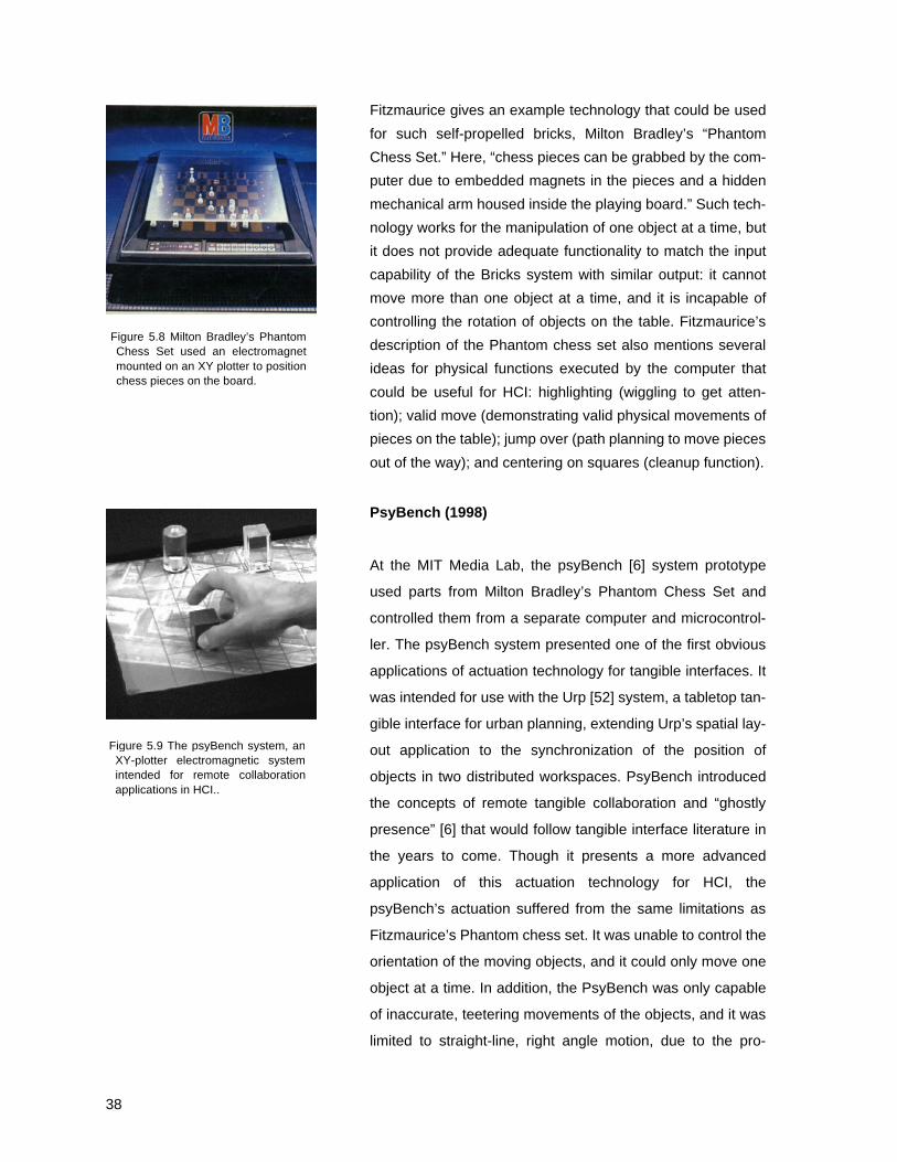
Modular Distributed Manipulator System (1997)
Another system, the Modular Distributed Manipulator System
(MDMS) [28] consists of an array of orthogonally oriented
wheels that support and move objects through combined vec-
tor forces created by the rotating wheels. This actuation
method presents a clever solution to the problem of friction
between objects and the table. Instead of dragging or sliding
objects on a continuous flat surface, the system moves
objects by rolling them along the tops of the wheels, doing
away with the friction between two flat surfaces. Because it is
an array-based actuation mechanism, the MDMS is scalable
to larger areas, requiring only that more actuators be set up
next to the existing array. The MDMS is intended for manipu-
lating large parcels, factory materials, or pieces of luggage in
a conveyor belt situation. Creating and controlling similar
actuators on the small scale required for the small pucks
Figure 5.5 The Modular DistributedManipulator uses orthogonally ori-ented rollers to rotate and translateobjects.
Figure 5.6 Using a variety of wheelmovements to achieve part transla-tion and rotation in the MDMS

37
used in HCI would present many challenges for mechanical
design. More significantly, the surface upon which objects
rest is neither flat nor continuous (because it is made up of
many small wheels), making it unsuitable for the projection
often used in tabletop tangible interfaces.
Magnetism: X-Y Plotters and Electromagnets
Claude Shannon’s Theseus (1952)
One of the first actuation systems that used magnetism to
move an object on a table was Claude Shannon’s robotic
mouse, Theseus, developed in the 1950’s [46]. Here, a
robotic mouse was equipped with sensors on its whiskers,
enabling it to sense contact with one of the walls of the maze,
at which point it would rotate ninety degrees and attempt to
move forward again. In this manner the mouse constructed a
map of the maze and could then run the maze a second time
without hitting a wall. This was perhaps one of the first “learn-
ing circuits” of its type, and this type of artificial intelligence
was the main thrust of Shannon’s research with the project.
The actuation mechanism was also a novel introduction:
electromagnets were mounted on an XY plotter under the
surface of the (aluminum) table, and magnetic forces
grabbed the metal mouse in order to move it on the table.
Multiple electromagnets were used, allowing the system to
rotate the mouse on the table. Theseus seems to be the first
documented instance of this XY-plotter and electromagnet
actuation system, used extensively in later HCI work as well
as in commercial toy chess sets.
Fitzmaurice’s “Self-Propelled Bricks” (1996):
In his Ph.D. thesis, Fitzmaurice describes a vision for Bricks
acting as both physical input and output devices, providing
not only “visual or tactile feedback but also position and
motion feedback” [13]. He suggests preliminary applications
for such technology, such as a desktop “cleanup” function
akin to the cleanup command then popular on the Macintosh
GUI operating system.
Figure 5.7 Claude Shannon and theTheseus project, a robotic mousecontrolled by an electromagnetmounted on an XY plotter unter thetable.
38
Fitzmaurice gives an example technology that could be used
for such self-propelled bricks, Milton Bradley’s “Phantom
Chess Set.” Here, “chess pieces can be grabbed by the com-
puter due to embedded magnets in the pieces and a hidden
mechanical arm housed inside the playing board.” Such tech-
nology works for the manipulation of one object at a time, but
it does not provide adequate functionality to match the input
capability of the Bricks system with similar output: it cannot
move more than one object at a time, and it is incapable of
controlling the rotation of objects on the table. Fitzmaurice’s
description of the Phantom chess set also mentions several
ideas for physical functions executed by the computer that
could be useful for HCI: highlighting (wiggling to get atten-
tion); valid move (demonstrating valid physical movements of
pieces on the table); jump over (path planning to move pieces
out of the way); and centering on squares (cleanup function).
PsyBench (1998)
At the MIT Media Lab, the psyBench [6] system prototype
used parts from Milton Bradley’s Phantom Chess Set and
controlled them from a separate computer and microcontrol-
ler. The psyBench system presented one of the first obvious
applications of actuation technology for tangible interfaces. It
was intended for use with the Urp [52] system, a tabletop tan-
gible interface for urban planning, extending Urp’s spatial lay-
out application to the synchronization of the position of
objects in two distributed workspaces. PsyBench introduced
the concepts of remote tangible collaboration and “ghostly
presence” [6] that would follow tangible interface literature in
the years to come. Though it presents a more advanced
application of this actuation technology for HCI, the
psyBench’s actuation suffered from the same limitations as
Fitzmaurice’s Phantom chess set. It was unable to control the
orientation of the moving objects, and it could only move one
object at a time. In addition, the PsyBench was only capable
of inaccurate, teetering movements of the objects, and it was
limited to straight-line, right angle motion, due to the pro-
Figure 5.8 Milton Bradley’s PhantomChess Set used an electromagnetmounted on an XY plotter to positionchess pieces on the board.
Figure 5.9 The psyBench system, anXY-plotter electromagnetic systemintended for remote collaborationapplications in HCI..

39
gramming of the mechanism. Positioning of the objects was
limited to a grid of 10 x 8 discrete 1” square cells, correspond-
ing to the positions of the square cells found in a chess set.
The system could only sense the position of the objects on
the table if the user pressed down on one of the chess
pieces, closing a membrane switch built into the surface of
the table. Even in 1998, tabletop tangible interfaces used
faster, less obtrusive object tracking technology than this
membrane switch.
Magnetism: Linear Induction Motor Concepts
Sumi-Nagashi and the Proactive Desk (2003)
Finally, at SIGGRAPH 2003 this year, an emerging technol-
ogy called the “Proactive Desk” will be presented [55] by
Japan’s ATR Media Information Science Lab. This system is
an array of electromagnets much like the Actuated Work-
bench, and provides force feedback to objects on top of a
table using the same principles of magnetic induction. After
the Actuated Workbench, fist published in 2002 [32], this sys-
tem is the second “2D Linear Induction Motor” actuation sys-
tem I have seen (Linear Induction Motors are explained in
Appendix A). The system’s designers use the Proactive Desk
in a haptic interface designed for interactive digital painting in
the manner of the traditional japanese art form “Sumi-
Nagashi.” Users move a stylus around on a tabletop while
interactive graphics are projected on the table around the sty-
lus. Magnetic forces from the table provide haptic feedback
based on the surrounding graphics in order to simulate the
real materials of the traditional art form. In addition to haptic
feedback for a stylus, the Proactive Desk’s designers use the
system to move a single “ink bottle” (an untethered object)
around on the table, creating even more similarities between
this work and the Actuated Workbench.
Figure 5.10 Sumi-Nagashi uses anarray of electromagnets called theProactive Desk to provide hapticfeedback in a digital painting apllica-tion.
40
6. Design and Development
Several design criteria govern my choice of materials and
mechanisms in designing the Actuated Workbench. Since the
goal of this project is to provide an actuation mechanism for
existing Tabletop Tangible Interfaces, it is important to keep
in mind what designs will and will not work with these inter-
faces for HCI. The following section describes some qualities
that seem desirable for a tabletop actuation mechanism for
use in Human-Computer Interaction, and includes a discus-
sion of the elements I used in attempting to achieve these
qualities in the Actuated Workbench.
6.1 Design Criteria
Desirable qualities of a tabletop actuation mechanism for HCI
include the following:
1. Actuation in multiple areas at once: A key interac-
tion technique in most interactive workbench inter-
faces is users’ ability to manipulate multiple objects
at the same time using both hands. The computer
actuation technology should be able to move multi-
ple objects at the same time. This way, it can main-
tain digital-physical consistency with every object
the user manipulates on the table simultaneously.
2. Ability to recreate human gesture: The system
should be able to recreate users’ gestural move-
ment (translation and rotation) with the objects on
the table with similar speed and resolution. This
ability is useful both for rewinding and replaying
movements as well as for remote collaboration. In
general, to achieve a “bi-directional” interface, the
actuation should be able to keep up with users’
movements, matching them for speed and resolu-
tion.
3. Compatibility with existing workbench architec-

41
ture: Since tabletop tracking technologies are rap-
idly evolving to provide better sensing resolution
and speed, the actuation mechanism should work
with existing tabletop tracking systems. It would be
difficult and time consuming to design a new track-
ing technology from scratch solely for use with this
actuation mechanism.
4. Size of physical objects and power consumption:
The physical objects should be comparable in size
to those in existing tabletop tangible interfaces.
This criterion limits the type of mechanism that can
be built into the objects. I originally considered
designing wheeled, motorized pucks that drive
themselves around the tabletop, but felt these
would be unnecessarily large compared to the lat-
est tagging technology. In addition, designing a
puck capable of both translating and rotating itself
on a surface might prove to be quite challenging.
Finally, motorized pucks require batteries that
might need to be changed or recharged frequently
due to the motors’ power requirements. Since
many tagging technologies used today are passive
devices, I sought to keep the actuation technology
passive as well. See Appendix C for discussion of
an emerging technology that contradicts this
assumption.
5. Projection: Existing tabletop tangible interfaces use
projection on and around the objects in order to
integrate physical input and graphical output in the
same space. Since the actuation mechanism is
intended for use with existing tabletop tangible
interfaces, the mechanism’s design should incorpo-
rate this projection. The objects and the surface of
the tabletop should therefore have flat, continuous,
opaque surfaces suited to displaying graphical pro-
jection from above.
6. Silent or near-silent operation: The actuation mech-
anism should be as un-obtrusive as possible. No

42
noise or unnecessary movement generated by the
interface should distract from users’ interaction with
the interface.
7. Scalability: The design should allow for expansion of
the actuation area for larger interactive surfaces.
6.2 Final Design Scheme
After considering many design options, including actuation
mechanisms similar to those described in chapter 2 (XY plot-
ters, wheeled pucks, robotic arms, and vibration), I decided
that magnetic actuation seemed the best approach for mov-
ing objects quickly and silently. Research into MagLev trains
and other magnetic technologies such as linear induction
motors suggested that a fixed configuration of magnets under
the table would be able to move magnetic objects on top of
the table. In order to move multiple objects simultaneously in
two dimensions, it seemed that a two dimensional array of
electromagnets would be necessary. The evolution of this
array and some explanation of MagLev and other technology
is described below in Appendix A.
Based on early experiments and on the above design criteria,
the Actuated Workbench’s hardware design uses a fixed
array of electromagnets that generate magnetic forces to
attract or repel permanent magnets built into each of the
moveable objects. The table surface and the objects on the
table are similar in size and shape to those used in existing
workbench interfaces, such as Sensetable [33], and the sys-
tem uses the same Zowie-based radio frequency technology
for tracking objects on the table. Though the electromagnet
array consists of discrete electromagnets, and therefore dis-
crete points of magnetic force, we have developed special
techniques for interpolating points of force between electro-
magnets. The system can control the strength of individual
electromagnets through pulse-width-modulation, a common
technique for driving DC electric motors at different speeds
by sending them pulses of various duty cycles depending on
the speed at which one wants the motor to turn. This makes it
possible to perform a physical “anti-aliasing” to create smooth

43
travel paths along the table between the discrete positions of
the electromagnets. This anti-aliasing is akin to graphical
anti-aliasing, in which the contour of a curved shape is
mapped onto the discrete pixels of a computer display
screen, and pixel color and brightness is computed based on
the overlap of the object’s shape with a pixel's area.
The Actuated Workbench design also includes custom elec-
tronics to independently set the strength and polarity of each
individual electromagnet in the array simultaneously, making
it possible to move multiple objects on the table by setting up
multiple moving magnetic fields in the array. The entire sys-
tem is addressed via a microcontroller that communicates via
Ethernet packets with any controlling computer running the
application program.
In practice, we decided not to incorporate a mapping for rota-
tion in our early applications, and therefore did not build rota-
tional control into the puck design of our first prototypes. Our
experiments show that the electromagnetic mechanism of the
Actuated Workbench can be used to control the pucks’ orien-
tation if we design larger pucks containing multiple magnets.
We can rotate objects using multiple magnetic fields to con-
trol two permanent magnets built into each object. A descrip-
tion and suggested uses for prototype rotational pucks
appears in Chapter 10.
In the following chapter, I describe technical details of the
Actuated Workbench system, including special techniques for
motion control.

44
7. Technical Details
The design and implementation of the Actuated Workbench
has set forth two significant innovations in computer-con-
trolled movement of objects. The first is the creation of a two-
dimensional array of electromagnets in order to move multi-
ple objects in two dimensions using magnetic induction. The
second innovation is the technique of modulating the electro-
magnetic array to achieve object motion that is interpolated
between the discrete positions of the electromagnets in the
array. This chapter contains a detailed description of the pro-
totypes we implemented between September 2001 and Jan-
uary 2003. It discusses the electronic components used and
the data handling sequence between computer and these
electronics. In addition to a detailed description of the Actu-
ated Workbench’s hardware, this chapter describes the
motion control techniques that, combined with this particular
arrangement of electromagnets, provides an innovative
method for achieving interpolated motion on top of the elec-
tromagnet array. Appendix A charts the evolution of the 2D
electromagnet array from my early research into magnetic
propulsion technologies.
7.1 System Description
Mechanical Details
The original Actuated Workbench prototype consisted of a
16.5 cm (6.5”) fixed array of 64 electromagnets arranged in
an 8 x 8 grid under a layer of 0.63 cm (¼”) acrylic (Figure
7.1). These electromagnets are held in place by a printed cir-
cuit board to which they were bolted and to which the leads
from the electromagnets are soldered (see Appendix D for
pcb layouts). Though this square array provides only a limited
area for actuation, its design to allows the tiling of several
arrays to create larger actuation areas. In the fall of 2002, we
expanded the array to 16 x 8, for a total of 128 electromag-
nets and an actuated area of 33 cm x 16.5 cm. The total size
of such a tiled-array actuation surface is limited only by the
Figure 7.1 The original ActuatedWorkbench prototype, with 1/4”acrylic surface.
Figure 7.2 The 8 x 8 array of electro-magnets, measuring 6.5” sq.
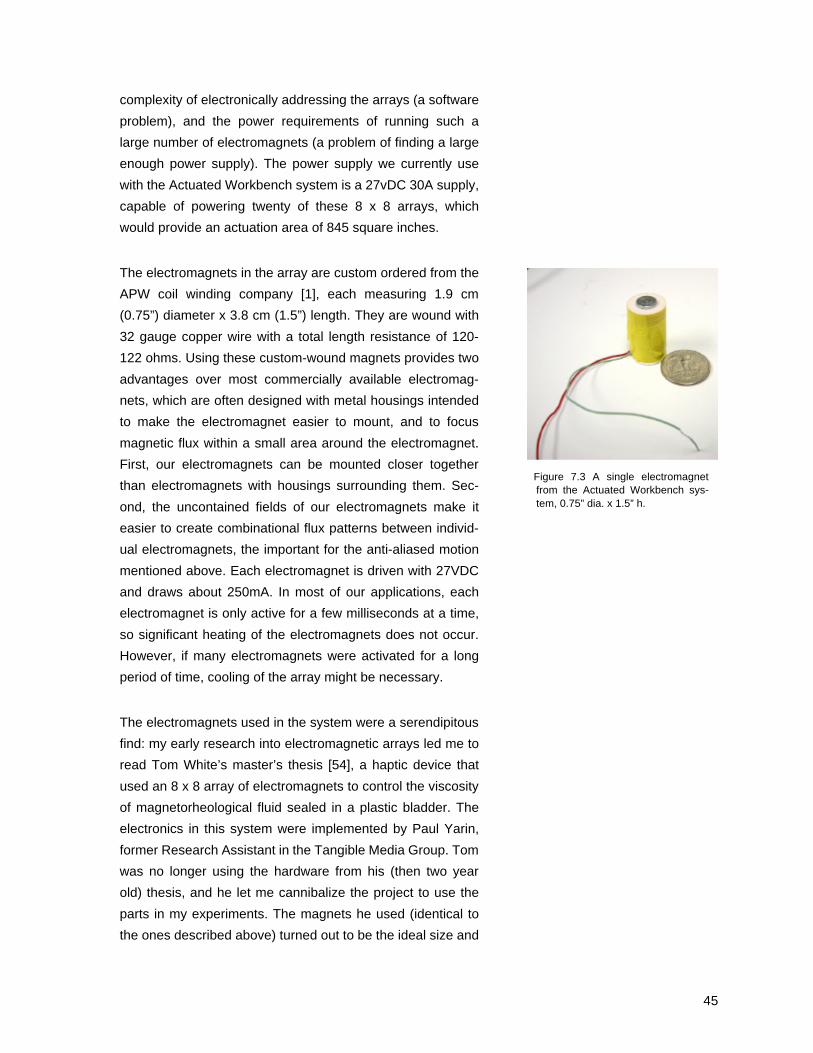
45
complexity of electronically addressing the arrays (a software
problem), and the power requirements of running such a
large number of electromagnets (a problem of finding a large
enough power supply). The power supply we currently use
with the Actuated Workbench system is a 27vDC 30A supply,
capable of powering twenty of these 8 x 8 arrays, which
would provide an actuation area of 845 square inches.
The electromagnets in the array are custom ordered from the
APW coil winding company [1], each measuring 1.9 cm
(0.75”) diameter x 3.8 cm (1.5”) length. They are wound with
32 gauge copper wire with a total length resistance of 120-
122 ohms. Using these custom-wound magnets provides two
advantages over most commercially available electromag-
nets, which are often designed with metal housings intended
to make the electromagnet easier to mount, and to focus
magnetic flux within a small area around the electromagnet.
First, our electromagnets can be mounted closer together
than electromagnets with housings surrounding them. Sec-
ond, the uncontained fields of our electromagnets make it
easier to create combinational flux patterns between individ-
ual electromagnets, the important for the anti-aliased motion
mentioned above. Each electromagnet is driven with 27VDC
and draws about 250mA. In most of our applications, each
electromagnet is only active for a few milliseconds at a time,
so significant heating of the electromagnets does not occur.
However, if many electromagnets were activated for a long
period of time, cooling of the array might be necessary.
The electromagnets used in the system were a serendipitous
find: my early research into electromagnetic arrays led me to
read Tom White’s master’s thesis [54], a haptic device that
used an 8 x 8 array of electromagnets to control the viscosity
of magnetorheological fluid sealed in a plastic bladder. The
electronics in this system were implemented by Paul Yarin,
former Research Assistant in the Tangible Media Group. Tom
was no longer using the hardware from his (then two year
old) thesis, and he let me cannibalize the project to use the
parts in my experiments. The magnets he used (identical to
the ones described above) turned out to be the ideal size and
Figure 7.3 A single electromagnetfrom the Actuated Workbench sys-tem, 0.75” dia. x 1.5” h.
46
power for my needs. They were strong enough to move
metallic and magnetic objects, yet small enough to be
arranged next to each other in a grid with a minimum separa-
tion between them. Furthermore, their cost was much lower
per electromagnet than any other commercially available coil
I could find. Tom’s contact information for the APW company
was several years out of date, and it seemed at first as if the
company was no longer in business, making it impossible to
find more coils. After months of searching, a random web link
led me to APW’s new site, and I was able to order more of the
same electromagnets the same day.
Electronics Details
The digital circuitry used to drive each 8 x 8 electromagnet
array went through several design iterations. The final design
includes custom circuit boards to drive each electromagnet in
the array bi-directionally, making it possible to set the polarity
of each magnet’s field, as well as turn individual magnets on
and off. The electronics are designed to set the state of each
electromagnet in the array at approximately the same time.
This makes moving multiple objects simultaneously a simple
matter of setting up separate magnetic fields in different
areas of the array. Of course, care must be taken that these
magnetic fields do not overlap when moving objects that are
close to each other, as this could cause one object to move in
the direction of a magnetic field intended for a different
object. Because a minimum distance of about 1/4” is needed
between objects in order to avoid crosstalk between electro-
magnetic fields, this consideration limits the number of
objects that can be moved simultaneously. In practice, we
have found that objects on the table do not come close
enough to each other due to the repulsion of the permanent
magnets built into each puck.
The electromagnet array is controlled by a software applica-
tion running on the PC. This software, an integral part of the
application with which the user interacts, determines which
objects on the table must be moved and sends the state of
every magnet in the array over Ethernet to a microcontroller
board. The microcontroller then parses the data and updates

47
the logic on the motor-driver circuit boards. The logic on the
circuit board connects to motor-driver IC’s which then con-
nect to the electromagnets. The following describes details
and evolution of this system.
Microcontroller
A SaJe board made by the Systronix company [48] handles
the transfer of data from the computer to the motor-driver cir-
cuit board. This microcontroller runs Java natively, at clock
rates of over 100MHz and provides 20 pins of I/O. The fact
that this microcontroller runs Java natively makes it extremely
well suited to setting up an Ethernet server to receive data
from the control computer. We developed a Java program to
run on the SaJe board that receives UDP packets sent via
Ethernet from the control computer, in this case, an IBM run-
ning windows. The Java program processes these packets
and converts the data for output on two parallel 8-bit data
buses. See Appendix E for microcontroller code.
Daughterboard
When we began tiling these 8 x 8 arrays to create larger actu-
ation areas, an intermediate layer of circuitry had to be
designed in order to multiplex the limited number of I/O pins
on the SaJe board to the 32 input pins needed to set the
polarity, enable (on/off) status, and clocks on the motor-driver
circuit boards. Therefore, I designed a daughterboard to sit
on top of the SaJe board, containing two additional octal
flops, and two 74HC138 demultiplexer chips. This circuit
board made it possible for the SaJe board to address four
coil-driver circuit boards, or two 8 x 8 arrays of electromag-
nets. See Appendix D for a schematic and PCB layout of this
circuit.
Coil-Driver Circuit Boards
Four 8-pin data buses then connect via ribbon cable from the
daughterboard to custom-designed printed circuit boards
containing eight octal D-type flip-flops and sixteen Texas
Instruments SN754410NE half-H motor driver chips. Each of
these circuit boards can drive 32 electromagnets indepen-
dently. The octal flops divide these 32 magnets into four
Figure 7.4 The SaJe real-time Javamicrocontroller board by Systronix.Also pictured is the daugtherboardwhich I designed to sit on top of it.
Figure 7.5 A daugtherboard designedto demultiplex signals from the SaJemicrocontroller board before sendingthem to the Coil-Driver circuit boards(Figure 7.6).

48
groups of eight magnets, so two of these circuit boards are
needed to drive one 8 x 8 array of magnets. The circuit
boards measure 6.25” square are stackable so that a “tower”
of coil-driver boards can be set up to save space.
Originally, my driver electronics used simple darlington tran-
sistor arrays to sink current through the electromagnets in
only one direction. These arrays included seven transistors
on one integrated circuit (IC), and were an inexpensive solu-
tion to the electronics needed by the system. Their useful-
ness was limited by their slow switching speeds, and the fact
that they could not be configured to drive the electromagnets
bi-directionally in the manner of an H-Bridge array (Figure
7.7), as the transistor arrays shared a common emitter on
each IC. An H-bridge transistor configuration was crucial to
driving the electromagnets in the array bi-directionally, which
is required for some of the advanced movement control tech-
niques described below.
While I considered making 64 H-bridges out of discrete
power transistors, the search for an IC led me to find Texas
Instruments’ SN754410NE quad half-H motor driver IC (Fig-
ure 7.8). Each of these 16 pin IC’s contains four half H-
bridges, allowing the configuration of two independent H-
bridges per chip. They are capable of driving up to 36vDC at
1A through a load, and contain internal diodes to provide pro-
tection from the kickback inherent in driving inductive loads
(Figure 7.7). There are of course many other motor-driver
chips available on the market today, such as National Semi-
conductor’s LMD series.
Data Handling
The data handling sequence with this daughterboard looks
like this:
1. The Saje microcontroller board receives packets froma control computer running a software application.This can happen as often as once every 15 micro-seconds.
2. The polarity of a row of magnets is clocked off the
Figure 7.6 A motor-driver circuitboard, each of which can drive 32coils independently.
Figure 7.7 An H-Bridge configurationof mechanical switches allows a load(such as a motor) to be driven ineither direction. Note “flyback”diodes to protect against inductivekick from the load.
Figure 7.8 Pinout for theSN754410NE, including logic tablefor H-Bridge outputs.

49
SaJe board into an octal register on the daughter-board.
3. The enable status of the same row is clocked intoanother register.
4. Both the enable and polarity status for the entire roware clocked into octal registers on the motor driverboard, which immediately outputs them to the elec-tromagnets.
The low propagation delay of the digital logic on the motor-
driver boards allows us to use pulse-width-modulation (PWM)
to vary the strength of each electromagnet’s field. PWM is a
common technique for driving electric motors at different
speeds by sending them pulses of various duty cycles
depending on the speed at which one wants the motor to turn
(Figure 7.9). PWM drives the coils with an average current
without the need to waste power or circuit board space on a
linear power element (which would vary the current based on
an analog voltage level or a variable current source).
Movable Objects
The magnetic forces of the Actuated Workbench system is
capable of moving any lightweight ferromagnetic object, such
as a paperclip or steel bolt.
Since the Actuated Workbench is to be integrated with exist-
ing tabletop tangible interfaces, we chose to use “pucks” as
the basic objects to be manipulated by users and the com-
puter in our interface, modeling our design on a smaller ver-
sion of the puck used in the Sensetable system. Our pucks
are made of layered pieces of ¼” clear acrylic. Each holds a
powerful (1.1 Tesla) neodymium magnet 1.26 cm x 1.26 cm x
0.63 cm (½” x ½” x ¼”) that provides the strong attractive
forces needed to drag the 14g (0.5oz) pucks around on the
Active Workbench’s acrylic surface.
In order to harness more force for moving objects, we built a
permanent magnet into each puck, providing not only more
magnetic attraction between the puck and each electromag-
net’s field, but also making it possible to use repulsive as well
Figure 7.9 Pulse-Width Modulation(PWM) signals representing varyingduty cycles of a load. PWM is aneffective means of driving motors atvarying speeds with digital circuitry.

50
as attractive forces for moving objects on the table. A ‘push-
pull’ technique can be used to move heavier objects or over-
come problems of friction between the puck and the table.
Care must be taken to ensure that the repulsive forces do not
accidentally flip the pucks over, though this type of motion
might be desirable for other interactions (see Chapter 10).
Puck Tracking Technology
Vision Tracking
The original puck design incorporated elements from a
vision-based tracking system. These pucks measured 2.54
cm (1”) diameter x 2.54 cm (1”) height, and in addition to the
permanent magnets contained a coin-cell battery, an IR led
for vision tracking and a switch to save the battery when not
in use (Figure 7.10). The inclusion of a battery violated the
design goal of keeping the pucks passive, but it was a neces-
sary solution, as we encountered preliminary difficulties with
electromagnetic sensing. We embedded each puck with a
small battery and an infrared LED, and suspend a camera
directly above the Actuated Workbench. Adding an infrared
filter to the camera blocks out ambient fluorescent light, mak-
ing the video signal easy to process (Figure 7.11). We used
an inexpensive Intel PC Camera Pro USB CCD camera and
were able to achieve a tracking rate of 30 updates per sec-
ond. This frame rate, though high from a human interaction
standpoint, is somewhat slow from a control systems per-
spective. However, since this is a limitation of the capture
rate of the device, we could have improved tracking speed by
replacing the USB web cam with a high-end frame grabber.
The vision-based puck tracking software, written by Dan
Maynes-Aminzade, tracked the infrared LEDs in the pucks by
detecting bright regions within the image captured by the web
cam. The image histogram was used to compute a threshold
value on startup, and the threshold is used to divide the gray-
scale image into zeros and ones. We then employed stan-
dard blob-analysis techniques [22] to determine the longest
horizontal segments. Simultaneous real-time tracking of mul-
tiple pucks was accomplished using an association method
Figure 7.10 The original Actuated Work-bench puck, containing an IR LED, bat-tery, and switch for Vision Tracking,
Figure 7.11 The Actuated Workbenchas viewed by the computer visionsystem, left, and the same imagewith an IR filter placed over the cam-era.

51
[2] to distinguish the pucks between frames. In every frame,
the software associated each observed location with the clos-
est puck location in the previous frame. This association
method is not wholly reliable, since puck paths that cross
each other can interchange identities, but since the perma-
nent magnets inside of the pucks tend to repel each other,
pucks rarely get close enough for this method to break down.
LC Tag Tracking
Our difficulty in using the Actuated Workbench system with
the electromagnetic tracking technology was due to distor-
tions created by the strong magnetic fields of our electromag-
nets. These magnetic distortions caused our tracking data in
the Zowie-based system to be very inaccurate, since the
magnetic fields changed the inductance of the coils in the LC
circuits of the tags, changing their resonant frequencies. We
later overcame this problem through automatic frequency cal-
ibration in the tracking system’s API. Six months later, we
had successfully integrated the Sensetable tracking platform
with the magnetic actuation platform and could track and
move objects without the two technologies interfering with
each other.
The final version of our pucks measures 3 cm diameter x
1.25 cm height (1.2 cm shorter than the initial prototype), and
holds a permanent neodymium magnet and an LC radio fre-
quency tags from the Zowie tracking system (Figure 7.12).
Each puck also contains a small momentary pushbutton
switch that shorts out the LC tag when pressed. This push-
button provides an additional method of input over the simple
positioning of objects on the table. For example, in one appli-
cation, pushing the button allows the user to toggle in and out
of interaction modes (scroll, zoom, rotate) when navigating a
map with the object. The user pushes the button on the puck
once in order to “lock down” that puck onto a position on the
map, and then pushes the button again in order to release
the puck. This and other interactions are described in Chap-
ter 9.
Figure 7.12 The final Actuated Work-bench puck design (exploded). Visi-ble are the Zowie LC tag and theround permanent magnet.

52
Mechanical Detail: Friction
The surface of the first Actuated Workbench prototype was a
polished piece of clear acrylic mounted directly on top of the
electromagnetic array. We attached a felt pad to the bottom
of each puck to provide the necessary kinetic friction to keep
the object from sliding around uncontrollably on the table’s
surface -- bare acrylic-on-acrylic is too slippery, resulting in
oscillations as the puck slides past its goal and is then
attracted back to it. The damping quality of the felt pad also
helps to smooth the motion of the puck on the table surface
as it passes between discrete positions of electromagnets in
the array. In this way, the felt pad acted kind of like a low-
pass filter on the somewhat jagged edges created by discrete
points of force of the electromagnets. Such filters are fre-
quently found on the output stages of digital-to-analog con-
verters such as those in compact disc players. They too help
to anti-alias the motion the pucks.
The 0.63 cm (¼”) thickness of the felt pad, combined with the
0.63 cm (¼”) bottommost acrylic layer of the puck, results in
the permanent magnet being about 1.26 cm (½”) from the
surface of the table, which is itself a piece of 0.63 cm (¼”)
acrylic. This positions the permanent magnet about 1.89 cm
(¾”) above the tops of the electromagnets. The height of the
permanent magnet in the puck has significant effects on the
performance of the system, since the neodymium magnet is
strong enough to be attracted to the ferrous cores of the
underlying electromagnets even when they are not activated.
This attraction increases friction on the object, which affects
the puck’s ability to slide on the surface. We found the
amount of friction between the pucks and the table to be a
critical element in the system’s ability to create smooth 2D
motion. In general, we observed that static friction (the friction
between the object and the surface when the object is at rest)
inhibited smooth motion of the pucks, while kinetic friction
facilitated smooth motion by controlling oscillations. After try-
ing a variety of materials, we initially found that felt-on-acrylic
gave adequate frictional characteristics, but later moved to a
piece of white card stock for the table surface and polished
acrylic for the bottom of the pucks. This provides a better sur-

53
face for viewing the graphical projection around the objects
while maintaining a coefficient of friction similar to that of the
felt-on-acrylic.
7.2 Motion Control and Interpolation
Manhattan Motion
Moving the puck across the table in a linear “Manhattan”
fashion (in straight lines at right angles to each other) is a
straightforward process. The puck can be moved to any grid
cell on the table by consecutively activating the electromag-
nets in neighboring cells at full strength (Figure 7.13). Using
Manhattan motion, objects can be moved across the table at
rates on the order of 25 cm/sec. (10in/sec.).
Smooth Motion
Though Manhattan motion can move the pucks rapidly
across the table, it is not so useful for recreating the smooth
gestural motions with which a user moves objects on an inter-
active workbench’s surface. The use of our anti-aliasing tech-
niques allows us to recreate user’s gestures with pucks
between the discrete positions of the electromagnets. In this
section we describe our mathematical model of the Actuated
Workbench and present the equations we used in our soft-
ware to produce smooth motion along arbitrary paths.
A single puck on the surface of the Actuated Workbench is
subject to gravitational force, frictional force, the magnetic
forces of attraction between the puck and the activated elec-
tromagnets, and the force of attraction between the perma-
nent magnet in the puck and the iron cores of the
electromagnets beneath. Figure 7.14 is a vector diagram
showing our force model.
We estimate these forces based on the duty cycles of the
magnets and add them to determine the total force on the
puck, the total force of magnetic attraction, and the net fric-
tion between the puck and the table surface. In reality, the
magnetic fields of the activated electromagnets interact in a
somewhat more complex manner (Figure 7.15), and the
Figure 7.13 Manhatten Motion:straight lines and right angles. justlike the big city.
Figure 7.14 Force Model: Attraction ofunderlying electromagnets, friction,and the normal force on the puck.
Figure 7.15 Magnetic field interactionsbetween electromagnets. The topimages show magnetic flux lines andthe bottom images map flux densityto brightness. The three image pairsshow the fields resulting from a sin-gle center magnet turned on (left),the left and center magnets turnedon (center), and all three magnetsturned on (right). The effect of thisfield-shifting behavior can be mod-eled approximately using force sum-mation. These images weregenerated with the VisiMag software

54
nearby ferrous cores of neighboring electromagnets return
much of the flux from the activated electromagnets, reducing
the range of force. In addition, the normal force on the puck
changes as it moves over the center of each electromagnet
on the table and the permanent magnet in the puck is
attracted to the iron core of the underlying electromagnet, so
the friction acting on the puck is constantly changing as well.
Since both of these forces are close magnetic fields, the force
between the puck and the electromagnets falls off at a rate of
, not linearly as in the simple force model we use. None-
theless, the force-summing model just described, in which
electromagnetic forces are treated independently of one
another and then summed, is a reasonable method of
approximating the more complicated underlying physics,
since the summation of multiple forces due to individual mag-
nets parallels the summation of multiple magnetic fields to
produce a single force.
There are many ways in which we could activate the electro-
magnets so that the resulting forces are summed to a vector
of desired magnitude and direction. In the next section, we
describe several different methods for choosing the magnet
values.
Anti-Aliasing Techniques
In computer graphics, the mathematical model of an image is
a continuous analog signal that is sampled at discrete points
called pixels. Aliasing occurs when the sampling frequency
(here, the number of pixels in a given area) is too low for the
signal frequency, resulting in a coarse image in which smooth
curves are converted to steps and jagged outcrops. The anti-
aliasing technique of prefiltering combats this problem by
treating each pixel as an area, and computing pixel color
based on the overlap of the scene's objects with a pixel's
area.
With the Actuated Workbench, we are faced with a similar
problem: we wish to render an analog signal (in this case, a
force of a particular direction and magnitude) using a discrete
1 r2⁄

55
array of cells (variable-duty electromagnets). To do so, we
can employ a similar technique: the strength of each electro-
magnet is determined by the “overlap” of its magnetic flux
lines with the location of the point force. Figure 7.16 shows a
configuration in which the forces of four neighboring electro-
magnets of different duty cycles combine to create a single
force of a new magnitude and direction.
“Dot”-based Anti-aliasing
The simplest algorithm for anti-aliasing draws the computer
graphics equivalent of a smoothed dot centered at the loca-
tion of desired travel. Given a desired force vector with head
at point (X, Y), we compute the distance from each electro-
magnet to (X, Y), and set its duty cycle in inverse proportion
to this distance. As in computer graphics, we can choose any
number of falloff metrics. We experimented with Gaussian
falloff, but found that in practice it was no better than a simple
linear falloff metric.
“Jet”-based Anti-aliasing
A drawback of the dot-based method is that it limits the
puck’s top speed of travel to about 15 cm/sec. (6in/sec.). In
order to produce enough force to move the puck, the center
of the dot must be positioned close to the puck, and the
forces produced by some of the activated electromagnets will
pull the puck backwards against the desired direction of
travel (Figure 7.17).
If we know the position of the puck and the direction of travel
that we hope to produce, we can pull the puck using only the
electromagnets located in this direction relative to the puck.
To do so, we first compute the vector from each electromag-
net to the target (X, Y), and then compute the scalar projec-
tion of this vector onto the direction-of-travel vector. Taking
the set of vectors of positive magnitude produces a collection
of forces resembling a “jet” in fluid mechanics (Figure 7.18).
Jet-based movement can move pucks across the table
almost as fast as Manhattan motion.
Figure 7.16 Different duty cycles infour neighboring electromagnetscombine to create a single force vec-otor for the object’s movement
Figure 7.17 “Dot-” vs. “Jet” based anti-aliasing. Magnet duty cycle is dis-played as the darkness of squaresnext to the pucks.
Figure 7.18 Another visualization of“Dot-” and “Jet”-based anti-aliasing.

56
We determine the strength of each electromagnet by drawing
a line between the current position of the puck and the
desired position, then mapping that line onto the discrete
positions of the underlying electromagnets, as one might do
in a graphical anti-aliasing situation. If the line does not fall
directly onto the exact position of an electromagnet, the
neighboring electromagnets are activated at lower strengths
so that the vector summation of all the magnets produces a
force along the direction of the line.
The location and strength of magnetic forces are constantly
updated by the software program when it receive position
data from the tracking system. This closed-loop feedback
system allows for dynamic changes in object movement, and
also provides a means for the computer to determine whether
its attempts at moving objects are successful. If the magnet
strength is not enough to move a puck on the table, the com-
puter can change the settings of the electromagnets to pro-
duce more force.
Stronger Movement
We also employ a “push-pull” method for moving pucks, in
which we simultaneously attract a puck to one point using
one magnetic polarity, while repelling it from behind using the
opposite polarity. This provides more force for overcoming
friction on the table. In practice, we have found this method to
produce faster motion, but the motion is not always so
smooth because it is difficult to control the direction in which
the puck will tend to move when presented with a repulsive
force

57
.
Table 7.19: Performance Metrics for the Actuated Workbench
Criterion Value
Number of trackable objects 9
Number of movable objects ~ 5 pucks for every 16 cm of table
Actuation area 16 cm sq min., scalable to larger areas
Max velocity ~ 10 cm / second
Accuracy of tracking ~2 mm
Resolution of positioning ~1 cm
Minimum distance between pucks ~1 cm
Power consumption 750 mA avg., 5 A max.

58
8. Evaluation
The task of evaluating an interface has several components,
including a review of its technical performance under any
conditions and a look at its overall interactive performance
when in use by a human. Using what measurements and
empirical observations we have at the time of this writing, I
will evaluate the Actuated Workbench prototype as imple-
mented in the latest revision of January 2003. My evaluation
focuses mainly on the Actuated Workbench’s technical per-
formance and its ability to satisfy my original design criteria,
and I discuss specific issues that impede the actuation sys-
tem in its attempt to create a bi-directional physical interface
for Human Computer Interaction. Finally, I outline a prelimi-
nary user study for the Actuated Workbench.
8.1 Original Design Criteria
In Chapter 6, I set forth seven design criteria with which I felt
one could judge an actuation mechanism’s suitability for
tabletop tangible interfaces. The Actuated Workbench’s abil-
ity to meet these criteria is reviewed here:
1. Actuation in multiple areas at once: The prototype
system is an array based mechanism capable of
moving multiple objects on the table at the same
time. This simultaneous movement is produced by
setting up multiple magnetic fields in different areas
of the array. Details of controlling this movement
are discussed in section 7.1.
2. Ability to recreate human gesture: Basic motion
control techniques, such as the ‘Manhattan motion’
discussed in section 7.2, can move objects on the
table at rates on the order of 10 cm/sec. However,
these speeds do not apply to the interpolated
motion of our ‘anti-aliasing’ techniques, in which
feed rates are about half as fast. The trade-off
between fast motion and high-resolution motion (a

59
smooth curved trajectory rather than a jagged one)
is inherent in the fact that the mechanism is made
from an array of discrete elements. If different elec-
tromagnets and stronger coil-driving circuitry were
used, the system would have more force to move
objects at faster accelerations, and yet might still
have the linearity needed to perform high-resolution
movements with our anti-aliasing motion tech-
niques. This remains to be seen in future revisions
of the system.
3. Compatibility with existing workbench architec-
ture: As discussed at the end of section 7.1, we
have developed automatic frequency recalibration
to overcome the interference between the Zowie
tracking technology and the Actuated Workbench’s
magnetic field. The Actuated Workbench is now
fully compatible with the high-resolution, low-
latency tracking of Sensetable 1.5.
4. Size of physical objects and power consumption:
Because our pucks are passive, containing only a
small LC tag and a small but powerful permanent
magnet, they are only 3 cm in diameter and 1.2 cm
in height. These measurements are smaller than
the pucks used in the Sensetable 1.5 system, satis-
fying our original design criteria.
5. Projection: The size and materials of the pucks and
the materials used on the table surface are quite
similar to those built into Sensetable 1.5, so projec-
tion on and around the pucks is highly visible.
6. Silent or near-silent operation: The only noise cre-
ated by the actuation system is the sound of the
acrylic pucks sliding over the paper surface of the
table, which is not audible during normal conversa-
tion around the table, and barely audible when
interacting silently with the interface. The sliding
noise of the pucks might actually be useful for call-
ing the user’s attention to the movement of pucks

60
she might not be watching, and for most interac-
tions would probably not be any more distracting
than the visual perception of the pucks moving
themselves.
7. Scalability: Because the basic 8 x 8 grid is tile-able, it
is relatively simple to expand the hardware to pro-
vide larger, seamless actuation areas. Of course,
the complexity of addressing this hardware from a
computer application increases as more tiles are
added. The ethernet addressability of the SaJe
microcontrollers mean that as more tiles and elec-
tronics are added, the number of cables between
computer and microcontroller need not increase, as
would be the case if they were addressed through
serial or other means. One can simply connect a
SaJe board to any ethernet hub and send ethernet
packets to the Actuated Workbench from any com-
puter.
8.2 Design Limitations
Friction and Strength
At the time of this writing, the major detractors to the Actu-
ated Workbench’s ability to move objects quickly smoothly on
the surface are 1) friction between the pucks and the table
surface and 2) the limited strength of the electromagnets.
Static friction between the pucks and the table makes it diffi-
cult to start objects moving, and once pucks begin to slow
down or change direction, friction starts to take over again
and pucks tend to get stuck in the middle of a trajectory on
the table. Any irregularities or foreign objects on the table sur-
face make it even more likely that a puck will get stuck mid-
motion. At the moment, we have not developed a sophisti-
cated method for dealing with this problem. As I will discuss
in Chapter 10, new types of motion control, such as the use
of repulsive forces to lower friction between pucks and the
table, could help overcome this problem. In addition, stronger
electromagnetic forces, either through coils with lower total
resistance or through driving the existing coils at higher-volt-

61
age, could help the system overcome the problem of friction
through brute force.
Coil-Drivers
The SN74410E half-H motor driver chips I used in my design
for the Coil-Driver circuit boards offer a convenient design for
incorporating 32 H-bridge circuits onto one circuit board.
Though these chips are capable of handling a large amount
of power for their small size, they can only switch a maximum
of 36vDC, and can source/sink maximum currents of 1A per
H-bridge. In my experiments to make the Actuated Work-
bench stronger, I ran into these maximum values as a limit on
the current I could pass through each electromagnet. Since
the internal resistance of each electromagnet is about 122
ohms, running 27vDC through each magnet only sinks about
225mA through each magnet. As the electromagnet’s coil
heats up (since current is passing through it), its internal
resistance rises and even less current flows through it, result-
ing in an even weaker magnetic field. A future redesign of the
coil-driver circuit boards using more powerful, higher-voltage
H-Bridge ICs would provide greater flexibility in choice of
power supply for driving the electromagnets. As the Actuated
Workbench is made stronger in future designs, care must be
taken to ensure the safety of users in the presence of such
strong magnetic fields, and to ensure that users’ credit cards
are not erased as they interact with the system.
SaJe Microcontroller
Although the Systronix SaJe microcontroller board’s native
Java J2me runtime environment makes it easy to set up
Ethernet-addressable I/O pins for controlling the coil-driver
circuit boards, it suffers from a classic pitfall of Java environ-
ments: garbage collection. This factor can cause unpredict-
able interruptions in the execution of the microcontroller’s
data parsing routine, causing the puck’s motion to be halted
mid-trajectory. I describe this garbage collection problem in
detail in Appendix B. At the moment the SaJe board is still the
simplest microcontroller unit for us to use with the system, but
in the future we may have to move to a different microcontrol-
ler in order to avoid this unpredictable problem. Other ether-

62
net equipped microcontroller boards, such as the Rabbit
boards made by Rabbit Semiconductor, might be easily sub-
stituted for the SaJe board.
Cost
At the time of this writing, each 8 x 8 electromagnet array,
including all driving electronics components, printed circuit
boards, and SaJe microcontroller board, costs just under
$1000 US to make. Much of this cost comes from the price of
the electromagnets ($4-6 US each, depending on quantity
ordered), and the cost of the SaJe microcontroller board
($500), which is intended as a development board and there-
fore contains additional hardware not required for the Actu-
ated Workbench. Both of these factors could be cost reduced
by fabricating custom parts (magnets and microcontroller
boards) in-house or finding a manufacturer that could provide
large-quantity discounts. I estimate that the cost of each 8 x 8
electromagnet array and its electronics could be brought to a
few hundred dollars. As mentioned above, the Zowie tracking
technology used with the Actuated Workbench was suffi-
ciently cost-reduced by the company that they could sell each
toy playset for under $50, suggesting that tabletop TUIs
might be less expensive and more common in the future. One
suggestion for a less expensive actuation mechanism is put
forth in Appendix C.
8.3 User Testing
We have not yet performed any formal user studies with the
Actuated Workbench system. We have outlined a preliminary
user study to test the benefits of actuation when applied to
the problem of maintaining consistency in tabletop tangible
interfaces. This study will measure subjects’ reaction times
when inconsistencies arise in a task performed on the Actu-
ated Workbench, and compare the cost of the user having to
correct the inconsistency manually (in a condition with no
actuation) with the benefit of having the system automatically
correct the inconsistency (in a condition with magnetic actua-
tion). It may turn out that the overhead manually correcting
inconsistencies amounts to very little increase in task com-
63
pletion times. It may also turn out that users subjectively
assess the cost of manually correcting physical inconsisten-
cies as being very low.
Nevertheless, we anticipate the large benefits in the use
actuation for remote collaboration applications, and hope to
test this hypothesis in our user study as well. In addition to a
scenario in which inconsistencies arise locally, we will also
conduct a user study that measures the same quantitative
and qualitative costs of inconsistencies in a remote collabora-
tion scenario. Here, the need to manually correct an inconsis-
tency on the table may interrupt the flow of dialogue between
remote collaborators.
In either case, it is my hypothesis that the conditions in which
actuation automatically maintains consistency between the
physical and digital states on the table will show improved
task completion times and will score better with subjects’
qualitative ratings of the interface. The results of this experi-
ment will help guide future work in actuation in tangible inter-
faces, and might point to unexpected applications for generic
actuation platforms such as the Actuated Workbench. At the
time of this writing, user studies are scheduled for the end of
May 2003.

64
9. Applications for the Actuated Workbench
In this section, I describe how the Actuated Workbench sup-
ports novel interaction techniques and new applications for
tabletop tangible interfaces. The section describes the exten-
sion of some basic GUI functions into the physical domain,
and then goes on to describe some higher-level applications,
including some solutions classic problems in tabletop tangi-
ble interfaces. We implemented some of these applications in
the winter of 2003, and details of the actual implementation
are discussed where relevant. Some applications mentioned
below require further development of the Actuated Work-
bench to address limitations of speed, magnetic strength,
scale, and resolution. These and other future developments
of the Actuated Workbench system are discussed in Chapter
10
9.1 Basic GUI Functions
One obvious application of the Actuated Workbench mecha-
nism is that of recreating activities in the GUI world with the
movement of objects in the physical world. We have not yet
implemented these functions in our current applications on
the Actuated Workbench, but they are listed here to introduce
the actuation’s potential for making tabletop TUIs as func-
tional as the generic GUI.
1. Search and retrieve: As the number of pucks
increases in an interactive workbench system, it
becomes more difficult for a user to keep track of
every data item on the table, just as it is difficult to
keep track of many graphical icons on a computer
desktop. A search and retrieve function could physi-
cally display the results of a user query, finding
matching data items and either moving them to
another place on the tabletop or wiggling them to get
the user’s attention (Figure 9.1). The use of physical
Figure 9.1 Calling user attention to aphysical object on the table by “high-lighting” it with a wiggling motion.

65
motion to grab user attention has been mentioned by
Fitzmaurice in his description of the Phantom Chess
Set, which draws the human player’s attention to a
specific chess piece by “highlighting” it with a wig-
gling or shaking movement [13].
2. Sort: A more powerful function would be one in which
the computer could physically sort and arrange
pucks on the table according to user-specified
parameters. This could help the user organize a
large number of data items before manually interact-
ing with them (Figure 9.2).
3. History and Undo: As a user makes changes to data
through physical input, she may wish to undo some
changes. A physical undo in this system could move
the pucks back to their positions before the last
change. It could also show the user the exact
sequence of movements she had performed. In this
sense, both “undo” and “rewind” commands are pos-
sible.
4. Save and Restore: Different arrangements of pucks
could be saved and physically restored by the com-
puter system. Much of the overhead in using tabletop
TUIs lies in the re-binding of pucks to computational
parameters when a saved application is run again.
Actuation allows the computer system to automati-
cally reattach pucks to parameters they were last
used to control.
5. Teaching and Guiding: Because the Actuated Work-
bench gives the computer the ability to recreate
users’ gestures with the pucks, it becomes possible
for the computer to teach the user something about
interacting with the system through physical ges-
tures. If certain gestures are used in the interface to
trigger certain commands (such as a shaking gesture
to unbind a puck from a data item, implemented in
the Sensetable 1.0 system), then the computer can
show a novice or a forgetful user how to make that
Figure 9.2 A GUI-style function ofphysically sorting pucks on the table.

66
gesture with the puck. This way, many of an applica-
tion designer’s commands can be taught to users
without the need for intensive human coaching. In
addition, if a user is uncertain how to proceed while
using a problem-solving or simulation system, the
computer could suggest a physical configuration of
the pucks. Fitzmaurice praises the Phantom Chess
Set’s ability to teach users to play chess by providing
“hint” moves and physical demonstrating valid moves
through the actual physical movement of the pieces.
9.2 High-Level Tabletop Interactions
Remote Collaboration
One advantage that tabletop tangible interfaces offer is the
ease with which multiple users can make simultaneous
changes to the system. Users can observe each other’s
changes as they are made, and any user can reach out and
physically change the layout of objects in the shared work-
space without having to grab a mouse or other pointing
device. In this regard, tabletop TUIs surpass mouse-based
graphical interfaces, in which there is only one input device
and therefore usually only one user actively controlling the
input, and in which the display area is a small-sized computer
monitor designed for viewing by only one person. Some GUI
applications support synchronous remote collaboration by
displaying multiple cursors or pointers for both the local user
and the remote user. The shared workspace exists only in the
digital world, making it easy to have multiple displays of a
workspace simply by having multiple GUI workstations. As
tabletop TUIs become more popular and common as com-
puter interfaces, one can imagine multiple users interaction
with a shared workspace through multiple tabletop TUIs.
Here, since both sets of physical objects represent an instan-
tiation of the same digital data, the physical states of the
objects must always be synchronized with the data and with
each other. Otherwise, the two users would be interacting
with two separate environments instead of one shared work-
space. In this scenario, a mechanism for physical actuation of

67
the pucks becomes valuable for synchronizing multiple physi-
cally separated tabletop TUIs.
One example of a system that could benefit from physical
synchronization is the Urp system [52], in which users manip-
ulate physical models of buildings on a table and the com-
puter displays simulation information in the form of projected
“digital shadows” around the buildings. “Distributed Urp”
(Durp) attempted to create distributed workspaces for collab-
oration between multiple remote users. Identical Urp systems
were set up in two separate locations, and the two systems
were synchronized through identical graphical projections
onto the workbench. However, if a user in one location
moved a building, only the “digital shadow” of the building,
and not the physical model, would move in the remote loca-
tion. Durp’s creators designed around this problem by having
only one physical model of any building in either space.
Users in one location had control of half the model buildings
tracked in the shared workspace. That is, they had half the
total number of physical models in one location, while users
in the remote location had control of the other half of model
buildings. In addition to avoiding inconsistencies between
multiple physical models, this technique solved any problems
of turn-taking or ownership that could arise from two users in
different locations trying to move the physical model of the
same building in two different locations.
Though I would prefer to avoid military applications for this
technology, it should also be noted that the synchronization
of remote physical objects on a tabletop would also have
great benefits for remote collaboration with ‘situation room’
displays for military and defense applications. Many of the
interaction techniques used in these displays are quite similar
to those used in the Urp application.
Actuation in Remote Collaboration
The Actuated Workbench provides another solution to the
design problem described above. Synchronization of the
models on the two remote tables becomes a simple matter of
putting permanent magnets inside the model buildings and

68
using the workbench’s electromagnetic forces to translate
and rotate the models. In addition to facilitating simple syn-
chronization of these models, the Actuated Workbench could
recreate remote users’ actual gestures with objects on the
table, adding greatly to the “ghostly presence” [6] sought in
remote collaboration interfaces. In early 2003, Dan Maynes-
Aminzade and myself developed a remote collaboration
application on the Actuated Workbench in order to demon-
strate the system’s performance in these tasks. We built two
actuated tables, each with a 16 x 8 array of electromagnets
(an actuation area of 33 cm x 16.5 cm), in the manner of the
final prototype system described Chapter 4. We then
designed a remote collaboration application around the task
of cellular tower layout. Here, users position pucks represent-
ing cellular towers on a map and are shown the coverage
area of each tower through projection on and around the
pucks (Figure 9.3). This scenario emulates the simplest
aspects of the Urp’s graphical shadows projected around
model buildings on the table.
Our two tables are synchronized in real time through their
actuation mechanisms. The system can handle multiple
object movements at the same time, and at present we are
using up to four pucks at once on each table, though we are
capable of tracking and actuating up to nine on each table.
The system also provides a small amount of haptic feedback
to remote users as they interact with the system. If two users
attempt to move the same cell tower at the same time on the
two different tables, they feel the magnetic pull of the actua-
tion mechanism trying to move the pucks to a synchronized
position on the table (the average of the two pucks’ posi-
tions).
We also incorporated the projection of the remote users’
hands around the pucks. We use two USB web-cams to cap-
ture real-time images of the users’ hands manipulating pucks
on the table, perform some thresholding and background
extraction (in order to only project users hands and not the
background) and project “shadows” of the users’ hands
around the pucks (Figure 9.4). These projections allow local
Figure 9.3 A detail of our cellulartower layout application. A tower’scoverage on the map is indicated bythe blue projection.
Figure 9.4 A remote collaborationapplication on the Actuated Work-bench. Shadows of the user’s handsare displayed on the adjacent table(left) which is synchonized with thetable on the right.
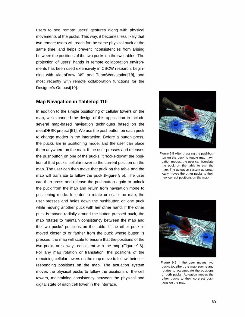
69
users to see remote users’ gestures along with physical
movements of the pucks. This way, it becomes less likely that
two remote users will reach for the same physical puck at the
same time, and helps prevent inconsistencies from arising
between the positions of the two pucks on the two tables. The
projection of users’ hands in remote collaboration environ-
ments has been used extensively in CSCW research, begin-
ning with VideoDraw [49] and TeamWorkstation[18], and
most recently with remote collaboration functions for the
Designer’s Outpost[10].
Map Navigation in Tabletop TUI
In addition to the simple positioning of cellular towers on the
map, we expanded the design of this application to include
several map-based navigation techniques based on the
metaDESK project [51]. We use the pushbutton on each puck
to change modes in the interaction. Before a button press,
the pucks are in positioning mode, and the user can place
them anywhere on the map. If the user presses and releases
the pushbutton on one of the pucks, it “locks-down” the posi-
tion of that puck’s cellular tower to the current position on the
map. The user can then move that puck on the table and the
map will translate to follow the puck (Figure 9.5). The user
can then press and release the pushbutton again to unlock
the puck from the map and return from navigation mode to
positioning mode. In order to rotate or scale the map, the
user presses and holds down the pushbutton on one puck
while moving another puck with her other hand. If the other
puck is moved radially around the button-pressed puck, the
map rotates to maintain consistency between the map and
the two pucks’ positions on the table. If the other puck is
moved closer to or farther from the puck whose button is
pressed, the map will scale to ensure that the positions of the
two pucks are always consistent with the map (Figure 9.6).
For any map rotation or translation, the positions of the
remaining cellular towers on the map move to follow their cor-
responding positions on the map. The actuation system
moves the physical pucks to follow the positions of the cell
towers, maintaining consistency between the physical and
digital state of each cell tower in the interface.
Figure 9.5 After pressing the pushbut-ton on the puck to toggle map navi-gation modes, the user can translatethe puck on the table to pan themap. The actuation system automat-ically moves the other pucks to theirnew correct positions on the map.
Figure 9.6 If the user moves twopucks together, the map zooms androtates to accomodate the positionsof both pucks. Actuation moves theother pucks to their corerect posi-tions on the map.

70
Zooming of the map is limited to physical limitations of the
pucks’ positions on the table. The pucks can only be brought
together to the point that they touch, so this imposes the
maximum zoom-out of the map. Since the pucks are only
detectable within the bounds of the tabletop’s surface area,
this imposes the maximum zoom-in possible for the map. In
practice, since cellular towers have a large coverage area,
there is little need to zoom in past this maximum. In both
cases, actuation moves the remaining pucks to the appropri-
ate positions on the map.
Simulation and Display for Interacting Objects
The Actuated Workbench could be helpful in the scientific
visualization of complex mechanical systems. For example, a
solar system model in the manner of an orrery (Figure 9.7)
could be created on a tabletop interface with full actuated
movement of pucks representing planetary orbits. By grab-
bing the pucks, users could change the physical properties of
the planets or teach the computer new orbit paths, and then
watch the resulting motions of the planets.
Similarly, the Actuated Workbench could be used to teach
students about physics by demonstrating the attraction and
repulsion of charged particles represented by pucks on the
table. As a student moves pucks around on the table, the
system could make the pucks rush together or fly apart to
illustrate forces between the objects.
Entertainment
In addition to these more practical applications, the Actuated
Workbench could be used to add a physical dimension to
computer entertainment. Though motorized chess sets have
existed for many years, they operate using a single electro-
magnet mounted on an x-y plotter mechanism, which are lim-
ited to moving one object at a time. The Actuated Workbench
could provide a significant improvement to these devices,
making them more flexible for a variety of games. Classic
computer games like Pong could now be played using a
physical puck and two physical paddles manipulated by the
Figure 9.7 An orrery showing the orbitof four moons around the planetJupiter.

71
users. Distributed Pong could be played with a local user
moving one paddle and the computer moving the puck and a
remote user’s paddle on the table. As I will discuss in Chapter
10, the Actuated Workbench can be used to flip over thin,
polarized magnetic pucks by rapidly reversing the polarity of
the electromagnets. This could be used to play a physical
game of Reversi with the computer. Finally, one could create
painting or drawing programs in which a pen or brush was
attached to the puck. The computer’s movement of the puck
could then be used to teach the user certain artistic gestures,
or even handwriting movements.
9.3 Haptic applications
Moving beyond GUI emulation, synchronization, and other
applications based only on the movement of objects, we can
design interactive functionality based on force-feedback and
physical objects whose physical behaviors are determined as
much by the computational state of the system as they are by
the objects’ shape and size. In this way, the physical proper-
ties of the objects in users’ hands can be as compelling a
medium for computer display as the graphics projected
around them or sound cues.
Simulating limits
As demonstrated by Snibbe [47], actuation in conjunction
with absolute input transducers can provide an effective
means of indicating the computational state of the system to
users, and allow users to rely on muscle memory when
returning to the input device. In the case of common tabletop
tangible interfaces, such as Sensetable, input devices are
physically generic round pucks, lending themselves more
readily to relative input than absolute input (at least this is
true in the case of rotation, if not position on the table). How-
ever, should we decide that an absolute transducer is appro-
priate for a specific input device, we can use actuation to
simulate limits through tactile feedback. For example, rotation
of a puck on the table could be limited to a certain number of
degrees, after which the computer activates magnetic forces
that resist users’ rotation of the puck. Similar constraints

72
could be used to limit the translatable positions of the puck,
making it act like a linear slider. In addition to physical limits,
“detentes” in the rotation of the puck could be simulated
through magnetic forces. Such detentes are common in
knob-based input devices such as audio mixers, where a
center detente indicates that an effect or filter is at its zero
point, halfway through the rotation of the knob. Furthermore,
physical qualities simulated by magnetic actuation of a puck
could change from parameter to parameter. A single input
device (puck) could have many different physical behaviors
as it is multiplexed among different parameters, each behav-
ior specific and appropriate for the parameter it is controlling.
For the user, such a design frees the interface from the clut-
ter of many different input devices for many tasks, while
maintaining the advantages provided by different physical
behaviors for each input device. For the interface designer,
the Actuated Workbench could reduce the overhead of
designing and physically fabricating multiple input device
qualities, and prototyping of the interface becomes more
rapid and less costly.
Getting in touch with real and virtual resistance
In the inTouch system (Figure 9.8), as the user manipulates a
set of three rollers in front of her, she also rotates three iden-
tical rollers on a remote unit. If a remote user resists her
motion by manipulating the remote inTouch unit, the user
feels resistance in the movement of her roller. The rotational
positions of the corresponding rollers are always synchro-
nized, and the use of strong motors for force feedback allow
each user to feel how much the remote user is resisting the
movement of the roller. According to inTouch’s creators,
these qualities contribute to the feeling that the two users are
manipulating the same roller, creating “the illusion of a
shared physical object across distance by physically synchro-
nizing the states of distant, identical copies of an object,
using telemanipulation technology” [6].
Similar concepts have been used to link other distributed
objects such as motorized teddy bears (Figure 9.9) [45],
Figure 9.8 Two inTouch units, physi-cally synchonized rollers separatedby a distance.
Figure 9.9 The RobotPHONE hapticlylinks two remote teddy bears in themanner of inTouch.

73
showing that the transmission of physical gesture over dis-
tance can occur through a variety of form factors.
These use of force feedback from tangible telepresence the-
ory [6] can extend beyond interpersonal haptic communica-
tion to haptic communication between user and data. If the
resistance of the movement of an object were not indicating a
remote user grabbing the remote object, but instead indicated
a computational constraint such as the difficulty in changing a
variable linked to the object, the object’s physical behavior
roller could impart this constraint physically to the user. For
example, a costly change in business practice could be dis-
played as resistance to the movement of a puck, while an
inexpensive change could be displayed as uninhibited move-
ment of the puck. In tabletop TUI, providing the pucks with
such haptic behavior could help users develop more intuitive
understandings of the behaviors and associations of interde-
pendent variables in a system.

74
10. Future Development
The final prototype of the Actuated Workbench satisfies most
of the basic design considerations established earlier in this
thesis. The system has been built with small passive pucks; it
can move multiple pucks at the same time; it can recreate a
range of user gestures with the pucks; it is silent because its
actuation mechanism has no moving parts. However, there
are still design refinements and implementation details that
need to be improved in order for the system to fully achieve
our goals of a truly bi-directional tabletop tangible interface.
10.1 Tiling of Arrays for Larger Surfaces
Since the current actuation area is only 6.5” x 13”, we plan to
tile four to six 8 x 8 arrays to form an actuation surface 13” sq.
to 13” x 19”, which should be large enough for use with most
interactive workbench interface systems. We also hope to
explore the use of different sizes of electromagnets. Smaller
electromagnets may yield higher resolution of object move-
ment on the table, while larger or more powerful electromag-
nets may provide more force for moving objects, making it
possible to provide stronger force feedback for tabletop TUIs.
Furthermore, using larger electromagnets would mean fewer
electromagnets per square inch of tabletop, perhaps resulting
in reductions in cost and complexity of the system.
10.2 New Types of Motion
Rotation
As mentioned in Chapter 7, experiments with different puck
designs have shown that we can use the Actuated Work-
bench to achieve puck rotation as well as translation. Our
prototype rotatable pucks consist of a 2” diameter puck con-
taining two zowie tags and two permanent magnets. We
mount the magnets inside the puck with opposite polarities
facing downwards (Figure 10.1). This magnet orientation
allows us to address each side of the puck independently,
Figure 10.1 A prototype rotationalpuck containing two Zowie tags forrotation tracking and two magnets,oriented with opposite polarities fac-ing downward to control rotationwith the Actuated Workbench

75
and perhaps could be used to achieve simultaneous rotation
and translation. Rotation of round pucks is not often used as
an input motion in tabletop tangible interfaces. It is possible
that this is due to the difficulty of rotating an unconstrained
puck quickly. The dials and knobs that we usually rotate as
input for devices such as stereos are constrained, or ‘pinned’
at the center of the dial, allowing us to make quick rotations
without having to worry about moving the whole dial. Jog
shuttles even provide an indentation for the user’s finger,
allowing multiple rapid rotations with just one finger. In his
Ph.D. Thesis, Brygg Ullmer argues that similar benefits are
provided by physical constraints for user input in TUI [50].
Tabletop TUIs do not have these physical constraints built in,
but it may be possible to use actuation to mimic such con-
straints in the motion of pucks on the table. For example,
magnetic attraction and repulsion could be used to allow the
user to spin a puck rapidly around its center while preventing
the accidental translation of the puck. A third magnet could
be built into the center of the puck, and could be used as a
virtual “pin” to hold the center of the puck still while the user
rotates it. In this way, the benefits of physical constraints for
physical interaction could be dynamically applied to objects in
an actuated tabletop TUI.
Flipping Pucks
In addition to controlling orientation, the Actuated Workbench
is also capable of flipping over magnetic objects or launching
them into the air by reversing the polarity of the electromag-
nets underneath the objects. If the polarities of the electro-
magnet and the permanent magnet in the object have
opposite orientations (such that the two north poles face each
other, for example), a strong repulsion results. This repulsion
could be used to flip over a double-sided object, so that the
opposite side is attracted downward. In his Ph.D. thesis [13],
Fitzmaurice also discusses “FlipBricks,” which use all six
sides of a Brick to implement different commands, saving
space by eliminating the need for a separate brick for each
command (Figure 10.2). Similar interactions were imple-
mented in the ToolStone project [38]. Similarly, the flipping of
Figure 10.2 FlipBricks mockup byGeorge Fitzmaurice. The user canturn different sides of a brickupwards to impose various com-mands with the same Brick.
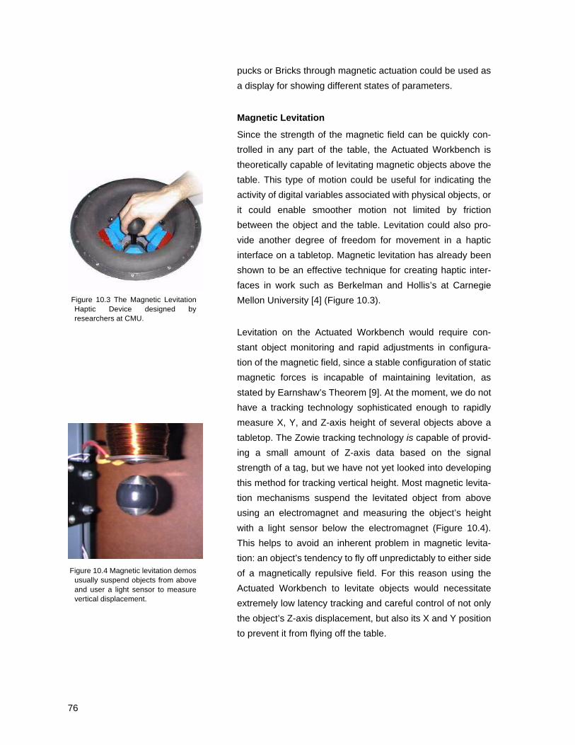
76
pucks or Bricks through magnetic actuation could be used as
a display for showing different states of parameters.
Magnetic Levitation
Since the strength of the magnetic field can be quickly con-
trolled in any part of the table, the Actuated Workbench is
theoretically capable of levitating magnetic objects above the
table. This type of motion could be useful for indicating the
activity of digital variables associated with physical objects, or
it could enable smoother motion not limited by friction
between the object and the table. Levitation could also pro-
vide another degree of freedom for movement in a haptic
interface on a tabletop. Magnetic levitation has already been
shown to be an effective technique for creating haptic inter-
faces in work such as Berkelman and Hollis’s at Carnegie
Mellon University [4] (Figure 10.3).
Levitation on the Actuated Workbench would require con-
stant object monitoring and rapid adjustments in configura-
tion of the magnetic field, since a stable configuration of static
magnetic forces is incapable of maintaining levitation, as
stated by Earnshaw’s Theorem [9]. At the moment, we do not
have a tracking technology sophisticated enough to rapidly
measure X, Y, and Z-axis height of several objects above a
tabletop. The Zowie tracking technology is capable of provid-
ing a small amount of Z-axis data based on the signal
strength of a tag, but we have not yet looked into developing
this method for tracking vertical height. Most magnetic levita-
tion mechanisms suspend the levitated object from above
using an electromagnet and measuring the object’s height
with a light sensor below the electromagnet (Figure 10.4).
This helps to avoid an inherent problem in magnetic levita-
tion: an object’s tendency to fly off unpredictably to either side
of a magnetically repulsive field. For this reason using the
Actuated Workbench to levitate objects would necessitate
extremely low latency tracking and careful control of not only
the object’s Z-axis displacement, but also its X and Y position
to prevent it from flying off the table.
Figure 10.3 The Magnetic LevitationHaptic Device designed byresearchers at CMU.
Figure 10.4 Magnetic levitation demosusually suspend objects from aboveand user a light sensor to measurevertical displacement.

77
Even if full levitation is not possible (or useful) in the future,
small repulsive forces could be used to provide greater con-
trol over the friction between pucks and the table surface.
Giving the pucks a small “kick” to help them overcome static
friction, or using repulsion as well as attraction to create a
push-pull actuation system could result in new motion possi-
bilities. As mentioned in Chapter 7, friction between the puck
and the table surface plays a large role in the smoothness of
objects’ motion on the table. The selective attraction and
repulsion of pucks could be used not only to control X and Y
motion, but also the friction between the object and the table
surface selectively damping motion by dynamically adjusting
the coefficient of friction. Controlling the friction between
objects and the table is actually the basis for the movement
of objects in the Universal Planar Manipulator [40], so friction
rather than magnetic inductance could be used as the main
force of movement in future motion techniques on the Actu-
ated Workbench.

78
11. Conclusion
The Actuated Workbench’s Contribution: A Patch or an
Innovation?
Since the Actuated Workbench was designed for use with
existing tabletop tangible interfaces, many of the preliminary
application ideas described above focus on its ability to
resolve inconsistencies commonly found in interactions with
tabletop tangible interfaces. There is clear value in a technol-
ogy that can solve such problems. However, these applica-
tions raise the question whether a tabletop actuation
mechanism such as the Actuated Workbench exists only to
solve problems created by the advent of tabletop tangible
interfaces in the first place, or whether its technology has far-
ther reaching implications. I believe the latter to be true, as I
have implied in some of the suggested applications for hap-
tics as well as in some of the background theory advocating
tabletop actuation. The Actuated Workbench represents a
step along the way toward bi-directional physical interaction
between user and computer, and hopefully other projects will
take us far beyond the Actuated Workbench’s contribution
toward this goal.
Trends in TUI Input and Output
The trend in TUI input devices has been movement from spe-
cific, non-reconfigurable, tethered objects that are separated
from the graphical output space, toward generic, highly
reconfigurable, untethered objects, collocated with graphical
output. This trend has made tangible interfaces more flexible,
such that objects with specific form factors are not required
for each application running on the table, and a variety of
user input gestures can be sensed and used in interaction.
Furthermore, this trend has reduced the obtrusiveness of the
technology built into the interface, making for a more “seam-
less” [19] transition between the physical and digital worlds.
My vision for physical output devices follows much of this
same trend. Previous work with haptic output devices such
as the PHANToM™[29] or Snibbe’s et al.’s ‘Haptic Tech-

79
niques for Media Control’ [47] use specific, non-reconfig-
urable form factors, tethered objects, and have been located
away from graphical output. Tabletop actuation systems like
the Actuated Workbench provide a mechanism that supports
the evolution of even actuated tabletop tangible interfaces
toward generic, reconfigurable, untethered devices collo-
cated with graphical output. The actuation system, like the
sensing system, is designed to be as un-obtrusive as possi-
ble: it requires no batteries, can be built into objects of many
form-factors, and is silent. The actuation system’s ability to
maintain consistency between physical and digital states
helps maintain the seamlessness of tabletop TUI systems, in
some cases even restoring seamlessness where it breaks
down during inconsistencies between digital and physical
states.
It is my hope that new actuation mechanisms will continue to
develop alongside new sensing technology, such that physi-
cal input and output can be further integrated into seamless,
flexible interfaces. As time goes on, new electronic sensing
technology will allow computer interface designers to recog-
nize more and more types of human gesture, either through
the manipulation of physical objects or free movement in thin
air. The physical-digital bottleneck will continue to widen, and
users’ intentions will be flow without inhibition into computer
actions.
The opposite transition, the flow from computer to human,
has evolved more slowly. Graphical output has been identi-
fied as the richest mode of information transfer between com-
puter and human, and as such has suffered a glut of overuse
by interface designers. Users’ visual senses are suffering
from visual over-stimulation, both in the foreground of their
computer interaction and in their periphery, as in interface
techniques such as ‘ambient media’ [20] vie for attention (Fig-
ure 11.1). Fully immersive, “virtual reality” graphical environ-
ments have been around for decades, but have not caught
on as the dominant computer interface, perhaps because so
much human work still happens in the real physical world.
Augmented reality, a blending of the real world with the virtual
Figure 11.1 Hiroshi Ishii’s sketch offoreground and background userattention shows GUIs and TUIs in asthe main focus of user attention, andambient media at the periphery ofuser attention.

80
world, has become increasingly popular in HCI research, and
it is even arguable that, because of their blending of digital
projection and physical objects, tabletop tangible interfaces
lie close to augmented reality in the interface spectrum. The
blending of real and virtual, physical and digital in these inter-
faces has brought us closer to a seamless interaction with
computation, but it has been a one-directional interaction. I
believe that systems for the computer-controlled movement
of physical objects will become one of the most fruitful areas
for HCI research in the coming years. This trend has already
shown itself in the increasing number of papers presented on
haptic devices for HCI at conferences each year such as CHI,
UIST, and SIGGRAPH.
What will the future look like?
My vision for the near future includes a mechanism that
allows any object to have behaviors beyond its physical prop-
erties. Tangible interface designers could use this device to
simulate gravity, lightness, inertia, and defy the natural phys-
ics of physical objects in order to provide users with a visual-
ization of digital state through physical objects. Magnetism
seems to be the most promising technology for such a mech-
anism, as it can achieve large, dynamic, and invisible forces
with small objects.
As more actuation technologies continue to be invented, we
may be able to create environments unlike any physical envi-
ronment we now know. Perhaps one day we will find our-
selves in environments whose physical properties are entirely
governed by computer control. We might find ourselves living
with force-fields in the air around us that simulate gravity or
that allow us to feel simulated resistance of our movements
with our bare hands rather than through intermediary physical
objects. Alternatively, users could hold small computer-con-
trolled gyros that spin themselves in different directions to
provide haptic feedback. Finally, direct neural input could be
used to provide haptic sensations without the need for com-
plicated actuation, but the invasive procedures required for
such input might drive some users away from this option. The

81
interfaces of the future may be entirely haptic, while our
visual attention is used for other non-computer interactions.
In the meantime, tangible interface design can further
emphasize the importance of physical objects in TUI by
including actuation as an output path. Graphical output is a
rich medium for feedback, and its place will probably always
be secure in tabletop TUI design. As actuation becomes
more prevalent in tangible interfaces, it will further secure the
importance of physical feedback and physical interaction in
computer interfaces. The Actuated Workbench represents
another step furthering the cause of tangible interfaces, clos-
ing a previously open loop for physical interaction. As work in
actuated interfaces continues in the future, I believe we will
see more progress toward truly bi-directional tangible inter-
faces.s.
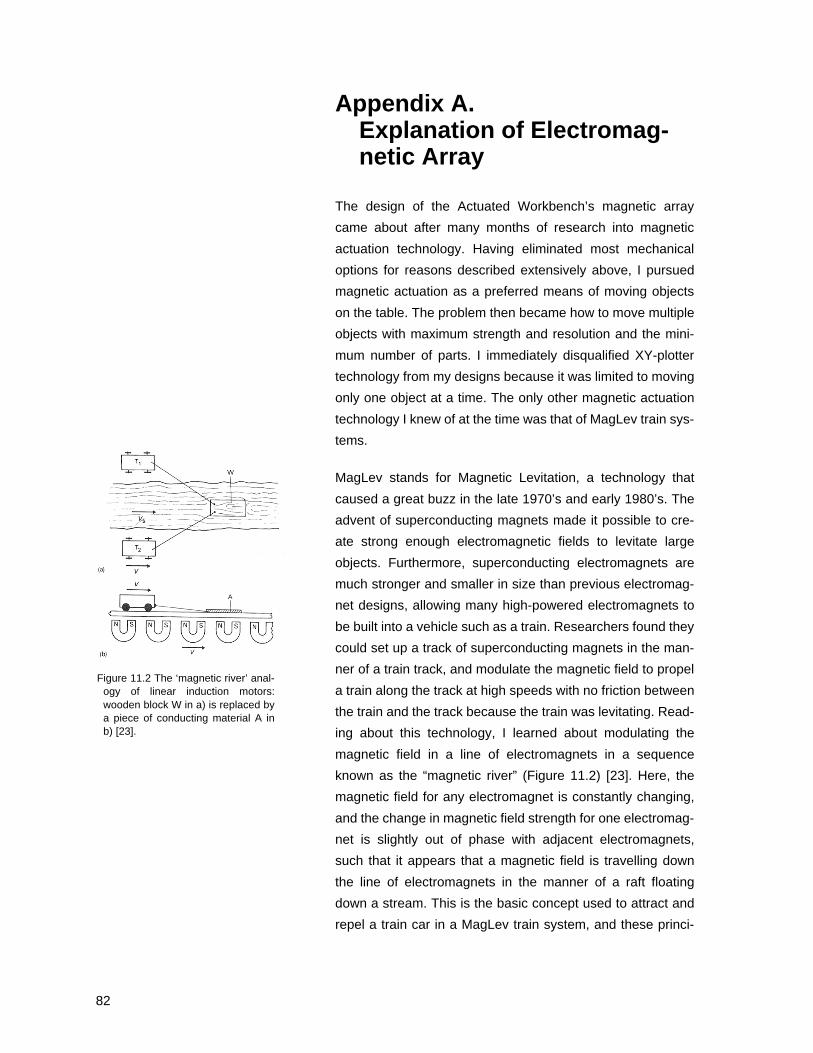
82
Appendix A.Explanation of Electromag-netic Array
The design of the Actuated Workbench’s magnetic array
came about after many months of research into magnetic
actuation technology. Having eliminated most mechanical
options for reasons described extensively above, I pursued
magnetic actuation as a preferred means of moving objects
on the table. The problem then became how to move multiple
objects with maximum strength and resolution and the mini-
mum number of parts. I immediately disqualified XY-plotter
technology from my designs because it was limited to moving
only one object at a time. The only other magnetic actuation
technology I knew of at the time was that of MagLev train sys-
tems.
MagLev stands for Magnetic Levitation, a technology that
caused a great buzz in the late 1970’s and early 1980’s. The
advent of superconducting magnets made it possible to cre-
ate strong enough electromagnetic fields to levitate large
objects. Furthermore, superconducting electromagnets are
much stronger and smaller in size than previous electromag-
net designs, allowing many high-powered electromagnets to
be built into a vehicle such as a train. Researchers found they
could set up a track of superconducting magnets in the man-
ner of a train track, and modulate the magnetic field to propel
a train along the track at high speeds with no friction between
the train and the track because the train was levitating. Read-
ing about this technology, I learned about modulating the
magnetic field in a line of electromagnets in a sequence
known as the “magnetic river” (Figure 11.2) [23]. Here, the
magnetic field for any electromagnet is constantly changing,
and the change in magnetic field strength for one electromag-
net is slightly out of phase with adjacent electromagnets,
such that it appears that a magnetic field is travelling down
the line of electromagnets in the manner of a raft floating
down a stream. This is the basic concept used to attract and
repel a train car in a MagLev train system, and these princi-
Figure 11.2 The ‘magnetic river’ anal-ogy of linear induction motors:wooden block W in a) is replaced bya piece of conducting material A inb) [23].

83
ples have also been applied to rail guns and particle acceler-
ators.
Other research into magnets and motors taught me about
Linear Induction Motors (LIMs), which function in a very simi-
lar manner to MagLev trains, only without any levitation. A lin-
ear induction motor is basically a rotary motor, such as a
squirrel-cage motor unwrapped and laid flat (Figure 11.3),
such that the electromagnetic coils are mounted in a straight
line, rather than radially in a circle. Instead of a magnetic
rotor that is attracted to the activated coils in a sequence
such that it spins quickly, a magnetic object is attracted along
the sequence of electromagnets in a straight line. As is the
case with rotary motors, the rotor or puck need not be mag-
netic, but can also be a piece of conductive metal such as
copper or aluminum, due to the eddy currents that build up in
the metal due to the rapid modulation of the electromagnets’
fields. The Linear Induction Motor is the basic building block
of the Actuated Workbench’s electromagnetic array. Each 8 x
8 grid contains 8 rows of Linear Induction Motors, made up of
8 electromagnets each. This arrangement creates two sets of
eight orthogonally oriented linear induction motors, or a two-
dimensional linear induction motor. To my knowledge, this is
the first 2D linear induction motor, or more accurately, the
first “planar induction motor” in existence.
Coil designs
The coils in a linear induction motor are usually mounted in
an overlapping configuration (Figure 11.4) so that there is no
dead space between coils. This arrangement tends to
smooth the motion between adjacent coils, keeping the rotor
(the moving object) at a more or less constant velocity. My
early designs for the coil array in the Actuated Workbench
used overlapping coils in two dimensions (Figure 11.5). This
turned out to be a difficult configuration to make, and I exper-
imented with custom-made bobbins around which to wind the
coils so they could overlap. The biggest problem I encoun-
tered was the difficulty in getting enough windings on the
bobbins to generate a magnetic field of enough strength to
move anything. My homemade coils did not have enough
Figure 11.3 Explanation of a LinearInduction Motor (LIM) as anunwrapped version of a rotary squir-rel cage motor.
Figure 11.4 The overlapping coil con-figuration of a linear induction motor.
Figure 11.5 My original 2d overlap-ping coil scheme for the ActuatedWorkbench.

84
turns and therefore were very weak. I also attempted to
increase the flux density of my coils by adding an iron core in
between them. The difficulty here was in creating a design
where coils could be rapidly wound around a bobbin and then
an iron core inserted afterwards in the open spaces between
overlapping coils. I went through several design iterations
here (see Figure 11.6) but in the end, I had to abandon the
overlapping coil scheme due to the difficulty of winding coils
consistently enough with a minimum of open air in between
them, which also detracted from the flux density.
The final design, using store-bought (though custom wound)
electromagnets with iron cores, seemed limited at first
because of the discrete positions of the electromagnets and
the inherent dead space in between them. Eventually, as the
circuitry for driving these coils became more sophisticated
and efficient, we developed the anti-aliasing techniques that
smoothed over the discrete positions between the coils. The
rest is, well, history.
It may be useful to revisit the overlapping coil scheme, as it
may lead to a higher resolution positioning system. It may
also be able to handle larger actuation areas with the same
number of coils. Further research into motors and coil-wind-
ing technology and theory could yield some interesting ideas
for future coil arrangements on the Actuated Workbench. I
believe that we have only begun to unlock the potential for
computer controlled movement using magnetic forces, and I
am excited to see the results that come about from future
work.
Figure 11.6 Designs for bobbins onwhich to wind coils for the overlap-ping coil scheme in Figure 11.5.

85
Appendix BLimitations of SaJe micro-controller
SaJe microcontroller
Though running Java natively on a microcontroller makes it
extremely simple to set up Ethernet-addressable hardware I/
O devices, the Java virtual machine running on these boards
suffers from one pitfall: garbage collection. The Java pro-
gramming language allows for the dynamic allocation of
memory as variables are created and destroyed within a pro-
gram. This allows the program’s writer to declare variables as
they are needed within a program, instead of having to
declare them (and allocate memory for them) at the begin-
ning of the program. The Java virtual machine then periodi-
cally checks on the memory allocated for these variables,
and ‘cleans up’ the memory allocated for objects no longer in
use so the memory can be used for future variables. This
cleanup, referred to as “garbage collection”, occurs at a time
determined by the program, and not by the programmer. Gar-
bage collection creates a problem for us when we try to rec-
reate a long gestures made by users moving objects on the
table. The duration of the motion requires many data packets
to be sent to the microcontroller, each of which the Java
application then stores in a single static array and overwrites
whenever a new data packet (containing the state of every
electromagnet in the array) is received. Though the array is
static in the program (it is pre-defined and should not require
allocation of additional memory after its first creation and ini-
tialization), a bug in the UDP interface we use causes the
program to create a new array (and allocate more memory)
each time a data packet is received, rather than simply over-
writing the old data in the existing array. The available mem-
ory is quickly eaten up by the creation of these arrays,
causing the Java program to perform a garbage collection
approximately once every two seconds, during which all other
processes on the microcontroller stop -- along with the
motion of all objects on the table. This garbage collection
problem makes it very difficult to create extended sequences

86
of smooth motion on the table. After many hours of careful
debugging, we have determined that the problem lies in the
Java interface and not in our code. However, even at the time
of this writing, another datagram (UDP) interface is still not
available for the SaJe board, and we are still stuck with the
garbage collection problem. It turns out not to be very notice-
able during most interactions with the system, only limiting
the system’s ability to record and replay long gestures.

87
Appendix COther Actuation Technolo-gies
ZipZaps
Late in 2002, the Radio Shack company released a line of
new battery-powered toy remote control cars called ZipZaps
(Figure 11.7). These four-wheeled cars measured less than
2” in length and only 1” wide, were radio controlled, had top
speeds of feet per second, used a pager-motor for an engine,
and could drive around on a flat surface for up to five minutes
on a single rechargeable coin-cell battery. Such miniaturiza-
tion calls some of my original design choices into question.
When designing the first Actuated Workbench prototype in
the spring of 2001, I made the assumption that motor-based
technology could not be sufficiently miniaturized to build into
a puck approximately 2” wide, the size of Sensetable pucks
at the time. ZipZap technology clearly proves me wrong,
though the noise that the small cars make while screeching
around on a tabletop would probably still prove to be prohibi-
tively distracting for HCI applications. Still, ZipZaps could
easily be equipped with the small LC tags used in the Zowie
tracking system and could be used to immediately create an
ad-hoc actuated workbench system, without the need for a
specially built, heavy table full of electromagnets. Since the
cars are radio-controlled, it would be relatively simple to cre-
ate a computer controller for these radio signals and have the
computer directly control the motion of each Zip Zap car on
the table. At the moment, Zip Zaps only provide two different
frequencies for radio transmission, limiting the number of
cars that can be operated in a specific area to two, but this
could be overcome with some simple circuit modification.
At the time of this writing, ZipZap cars sell for about $20
each, meaning that it would cost approximately $200-300
(including the cost of microcontrollers and additional electron-
ics) to equip a Sensetable system with an ad-hoc actuation
mechanism.
Figure 11.7 ZipZap remote controlcars could provide an alternate tech-nology for the movement of objectsin an actuated tabletop TUI.

88
Air Jets
One of the most frequent comments made by people seeing
the Actuated Workbench for the first time is, “you could use it
to play air hockey,” pointing out the system’s similarity to air
hockey tables in the entertainment industry. Air hockey tables
(Figure 11.8) emit jets of air from holes in the table surface in
order to levitate a lightweight puck above the table surface,
eliminating friction so that the puck can be knocked about on
the table with high velocity. More sophisticated control of
these air jets could allow precise positioning of multiple
objects on the table. A system at Xerox PARC, the AirJet
Paper Mover uses MEMs-printed air jets to control the 2D
position of a piece of paper with up to micron accuracy and
high feed rates. At the moment, this technology requires that
air jets be mounted both above and below the object being
moved (Figure 11.9), making such a system unsuitable for
tabletop TUI, but it is possible that similar technologies could
be developed to create a distributed air-jet actuator system
for 2D tabletop movement.
Figure 11.8 An air hockey table
Figure 11.9 Xerox PARC’s AirJetPaper Mover uses MEMs technol-ogy to control a large array of air jetsto move pieces of paper in twodimensions.

89
Appendix D.Schematics
This section contains schematics and images of printed cir-
cuit board (PCB) layouts for the electronics I designed for the
Actuated Workbench system. All schematics and PCB files
were created using Protel 99 SE software.

90
Coil-Driver Circuit Schematic:

91
Coil-Driver Circuit PCB

92
Daughterboard Schematic

93
Daughterboard PCB

94
Electromagnet Mounting PCB

95
Appendix EMicrocontroller Code
The following is microcontroller code written by Dan Maynes-
Aminzade and I to run on the Systronix SaJe board. It is a multi-
threaded Java Program that acts as an Ethernet server, receiving
UDP packets from the computer running the application and then
parsing them for output on the SaJe board’s I/O pins.

96
WG_pwm_Server_polarity.java
import java.io.IOException;import java.io.InputStream;import java.io.OutputStream;import javax.microedition.io.Connection;import javax.microedition.io.Connector;import javax.microedition.io.DatagramConnection;import javax.microedition.io.StreamConnectionNotifier;import javax.microedition.io.Datagram;
/** * Title: WG_pwm_Server_polarity.java * Description: New WeeGee_server for Saje board, incorporates polarity. * Copyright: 29 aug 2002 * Company: MIT Media Lab * @author: gian Pangaro*@version 1.0 */
public class WG_pwm_Server_polarity extends Thread{static DatagramConnection dgc; static Datagram dg; static WG_pwm_polarity pwmController = null; static byte[] buffer;private boolean packetFlag = false;
// ======================
public void WG_pwm_Server_polarity() {
}
public void setController(WG_pwm_polarity wc) { pwmController = wc; }
public void run() {
String connURL = "datagram://:6969"; System.out.println("Construct.");
try { dgc = (DatagramConnection) Connector.open(connURL, Connector.READ); // opens the datagram connection
System.out.println(dgc); } catch (Exception e) {
System.out.println("Failed to open sock"); return;
}

97
// the buffer is 128 bytes long plus one start byte // each byte contains the polarity and strength of one // magnet on the grid. -127 to 0 is negative polarity, // 0 to +127 is positive polarity try {
buffer = new byte[129]; dg = dgc.newDatagram(buffer, buffer.length);
} catch (Throwable t) { t.printStackTrace(); System.out.println("Someone threw something, but I caught it.");
} System.gc(); // a forced garbage collection to help lower the // rate of future garbage collections System.out.println("collecting garbage"); System.out.println("starting run"); while (true) { try {
dgc.receive(dg); // upon receiving a datagram packet handleData(dg.getData()); // call the handledata method in WG_pwm_polarity } catch (Exception e) { System.out.println(e); }
} } // end run
void handleData(byte[] dat) {
pwmController.handleData(dat); }} // end WG_pwm_Server_polarity

98
WG_pwm_polarity.java
import com.ajile.drivers.gpio.GpioPin;import com.ajile.drivers.gpio.GpioField;import java.lang.System;import java.util.*;
/** * Title: WG_pwm_polarity.java * Description: New WeeGee for Saje board, encorporates polarity. * Copyright: 29 aug 2002 * Company: MIT Media Lab * @author: gian Pangaro * @version 1.0 * * This code is written to update two full 8x8 WeeGee grids, using * the new WGdemux board, which holds two octal flops and two hc138's. * The Saje board receives UDP packets, then parses them for polarity and intensity of * each magnet. The Polarity (rowPolarity*) and Enable status (rowState*) then get clocked * one-by-one into the octal flops on the demux board, and then both are clocked simultaneously * into one of the four WeeGee driver boards. So, basically it demuxes one 8pin data bus * onto two 8pin buses */
public class WG_pwm_polarity extends Thread{ // ================================================== // output port and variable declarations // =================================================
static GpioPin pwm_wiggle; static GpioField rowOutputPort; static GpioField rowClockPort;
static int[][] rowEnableOne; static int[][] rowEnableTwo; static int[] rowClockOne; static int[] rowClockTwo;
static byte[] rowPolarityOne; static byte[] rowPolarityTwo;
static byte[] rowStateOne = new byte[8]; static byte[] rowStateTwo = new byte[8];
static int timer;
// ====================================================================== // OUTPUT PORT SETUP. // =====================================================================

99
public WG_pwm_polarity() {
//temp pwm_wiggle = new GpioPin(GpioPin.GPIOA_BIT3); pwm_wiggle.setOutputPin(true); // end temp
// initialize some important ports// IO port C is the output for rowClock// IO port E is the output for rowEnablerowOutputPort = new GpioField(GpioPin.GPIOE_BIT0, 8);rowOutputPort.setOutputField(true);rowClockPort = new GpioField(GpioPin.GPIOC_BIT0, 8);rowClockPort.setOutputField(true);
timer = 0;
// rowPolarityPort = new Parallel();
// initialize important variables.rowEnableOne = new int[8][8]; // holds a generic register for 8 magnetsrowEnableTwo = new int[8][8]; // holds a generic register for 8 magnetsrowClockOne = new int[8];rowClockTwo = new int[8];
rowClockOne[0] = 0x08; // rowClockOne array is the clock for the left. rowClockOne[1] = 0x09; // side of the board rowClockOne[2] = 0x0A; rowClockOne[3] = 0x0B; rowClockOne[4] = 0x0C; rowClockOne[5] = 0x0D; rowClockOne[6] = 0x0E; rowClockOne[7] = 0x0F;
// rowClockTwo[0] = 0x10; // rowClockTwo array is the clock for right side. rowClockTwo[1] = 0x11; rowClockTwo[2] = 0x12; rowClockTwo[3] = 0x13; rowClockTwo[4] = 0x14; rowClockTwo[5] = 0x15; rowClockTwo[6] = 0x16; rowClockTwo[7] = 0x17;
for(int x = 0; x < 8; x++){ for(int y = 0; y < 8; y++){ rowEnableOne[x][y] = 0; // start Enables all off } } for(int x = 0; x < 8; x++){ for(int y = 0; y < 8; y++){ rowEnableTwo[x][y] = 0; // start Enables all off

100
} }
rowPolarityOne = new byte[8];rowPolarityTwo = new byte[8];for(int i = 0; i < 7; i++){ // initialize rowPolarity* rowPolarityOne[i] = 0; // we'll only use attraction for now. rowPolarityTwo[i] = 0; // we'll only use attraction for now.}
System.out.println("board initialized");sendOutRows(); // clear everything on the board
System.gc(); }
// ==================================================== // delay_us() - microsecond delay method // =============================================
public void delay_us(int num){num = 2 * num;for(int i = 0; i < num; i++){ // 1 time through this loop takes ~0.569uS
// nop}
}
// ================================================= // handleData() // ========================================== public static void handleData(byte[] b) {
timer = (timer + 10) % 127;
if(b[0] != -1) { return; }
for(int x = 0; x < 8; x++){ rowStateOne[x] = 0; rowPolarityOne[x] = 0; rowStateTwo[x] = 0; rowPolarityTwo[x] = 0; for(int y = 0; y < 8; y++){ if(b[8*y+x+1] < (-timer)) { // if it's less than zero, then it's of the opposite polarity rowPolarityOne[x] |= (0x01 << y); // polarity: 0 == attraction, 1 == repulsion. rowStateOne[x] |= (0x01 << y); // enable state: 1 == on, 0 == off. } else if (b[8*y+x+1] > timer) { // checking against the timer to determine PWM duty cycle. rowStateOne[x] |= (0x01 << y); // enable state: 1 == on, 0 == off. } if(b[8*y+x+65] < -(timer)) { rowPolarityTwo[x] |= (0x01 << y);

101
rowStateTwo[x] |= (0x01 << y); // enable state: 1 == on, 0 == off. } else if (b[8*y+x+65] > timer) { rowStateTwo[x] |= (0x01 << y); } } } } // end handleData
// ======================================================= // "clearRows" // ========================================
public void clearRows(){for(int x = 0; x < 8; x++){ for(int y = 0; y < 8; y++){rowEnableOne[x][y] = 0; // start Enables all offrowEnableTwo[x][y] = 0; // start Enables all off }}
}
// ================================================================== // "sendOUtRows" // =================================================================
// ==============================================================// The folloing sets up the enable and polarity states for two side-by-side// grids of 64 magnets. it clocks them into an intermediate demux board (WGdemux)// and then finally out to each of the four WeeGee boards that hold the magnet drivers.// The format is complex, but the important thing to note is how the clock lines now work// (via an hc138).// 1)The upper two clock lines are used to clock the polarty and enable status// into the demux board (Clk7 is polarity, and Clk6 is Enable).// 2) Clk5,4 are used to enable the '138 that will clock each WeeGee driver board.// 3) Clk2,1,0 are used to select which clock line (0...7) goes low on the '138.// this is set up as a 3-bit number in binary.//// ================================================================ public static void sendOutRows() {
rowClockPort.setFieldState(0x00); // make sure clock lines are clearfor(int i = 0; i < 8; i++){ rowOutputPort.setFieldState(rowPolarityOne[i] & 0xFF); // setup polarityOne on output lines rowClockPort.setFieldState(0x80); // clock it into the polartiy flop on demux board rowClockPort.setFieldState(0x00); // make sure clock lines are clear rowOutputPort.setFieldState((rowStateOne[i]) & 0xFF); rowClockPort.setFieldState(0x40); // clock it into the enable flop on demux board rowClockPort.setFieldState(0x00);

102
rowClockPort.setFieldState(rowClockOne[i] & 0xFF); // clock both the polarity and //enable into driver board one
rowClockPort.setFieldState(0x00); // clear clock lines at end. rowOutputPort.setFieldState(rowPolarityTwo[i] & 0xFF); // setup polarityTwo on output lines rowClockPort.setFieldState(0x80); // clock it into the polartiy flop on demux board rowClockPort.setFieldState(0x00); // make sure clock lines are clear rowOutputPort.setFieldState((rowStateTwo[i]) & 0xFF); rowClockPort.setFieldState(0x40); // clock it into the enable flop on demux board rowClockPort.setFieldState(0x00); rowClockPort.setFieldState(rowClockTwo[i] & 0xFF); // clock both the polarity and
// enable into driver board two rowClockPort.setFieldState(0x00); // clear clock lines at end.}
} // end sendOutRows();
public void run() { clearRows(); while (true) { //long ms_one; //long ms_two; //ms_one = System.currentTimeMillis(); pwm_wiggle.setPinState(true); sendOutRows(); pwm_wiggle.setPinState(false); //ms_two = System.currentTimeMillis(); //System.out.println("pwm period is" + (ms_two - ms_one)); //System.out.println("sent out tha rows!"); yield(); } }
// ====================================================================== // Main method // ========================================================================
public static void main (String [] args) { System.out.println("WG_pwm_Server_polarity version 1.2");
WG_pwm_polarity pwmController = new WG_pwm_polarity(); WG_pwm_Server_polarity wServer = new WG_pwm_Server_polarity(); wServer.setController(pwmController);
Thread serverThread = new Thread(wServer); Thread pwmThread = new Thread(pwmController);
serverThread.start(); pwmThread.start();
} // end main} // end WG_pwm_polarity.java

103
References1. A.P.W. Co. Inc. Electromagnet supplier. (Authur K. Pfeil) 32
W. Main Street. Rockaway, NJ 07866 Tel. 973.627.0643 http://www.apwcoinc.com/
2. Bal-shalom, Y. and Fortmann, T.E. Tracking and Data Association. Academic Press, 1988.
3. Beetson, J.S. Visualizing Magnetic Fields: Numerical Equation Solvers in Action. Academic Press, 2001.
4. Berkelman, P., Hollis, R., and Baraff, D. Interaction with a Realtime Dynamic Environment Simulation using a Magnetic Levitation Haptic Interface Device. IEEE International Conference on Robotics and Automation, May 1999, pp. 3261 - 3266.
5. Biegelsen, D., Berlin, A., Cheung, P., Fromherz, M., Goldberg, D., Jackson, W., Preas, B., Reich, J., and Swartz, L.E.. Air-jet Paper Mover: An Example of Meso-scale MEMS. In: SPIE Int. Symposium on Micromachining and Microfabrication, 4176-11, San Jose, CA, Sept. 2000.
6. Brave, S., Ishii, H. and Dahley, A. Tangible Interfaces for Remote Collaboration and Communication. In Proceedings of CSCW '98, ACM Press, pp. 169-178.
7. Brave, S., Dahley, A., Frei, P., Su, V., and Ishii, H., inTouch, in Conference Abstracts and Applications of SIGGRAPH '98, ACM Press, pp. 115.
8. Buxton, W. There’s More to Interaction than Meets the Eye: Some Issues in Manual Input. In Norman, D.A. and Draper, S.W. (Eds.), (1986), User Centered System Design: New Perspectives on Human-Computer Interaction. Lawrence Erlbaum Associates, Hillsdale, New Jersey, 319-337.
9. Earnshaw, S. “On the Nature of the Molecular Forces which Regulate the Constitution of the Luminiferous Ether,” Transactions of the Cambridge Philosophical Society, v. 7, 1842, pp. 97-112.
10. Everitt, K.M., S.R. Klemmer, R. Lee, J.A. Landay. Two Worlds Apart: Bridging the Gap Between Physical and Virtual Media for Distributed Design Collaboration. CHI Letters, Human Factors in Computing Systems: CHI2003. 5(1): p. 553–560.
11. Excalibur Electronics. Talking Robotic Chess. <http://www.excaliburelectronics.com/roboticch.html>
12. Fitzmaurice, G.W., Ishii, H., and Buxton, W. Bricks: Laying the Foundations for Graspable User Interfaces. In Proceedings of CHI '95, ACM Press, pp. 442-449.
13. Fitzmaurice, G., Graspable User Interfaces, Ph.D Thesis., University of Toronto, 1996

104
14. Fitzmaurice, G. and Buxton, W. (1997). An Empirical Evaluation of graspable User Interfaces: towards specialized, space-multiplexed input. Proceedings of the ACM Conference on human Factors in computing Systems (CHI ‘97). 43-50.
15. Francetic, A and Shwe, H (2000), Smart Toys: Benefits of Technology-Enhanced Play. In _2000 Game Design Proceedings, www.gdconf.com/archives/proceedings/2000/shwe.doc
16. Frei, P., Su, V., Mikhak, B., and Ishii, H., curlybot: Designing a New Class of Computational Toys, in Proceedings of Conference on Human Factors in Computing Systems (CHI '00) , (The Hague, The Netherlands, April 1-6, 2000), ACM Press, pp.129-136
17. Hutchins, E. L., Hollan, J. D. and Norman, D. A. (1986). Direct Manipulation Interfaces. In D. A. Norman and S. W. Draper (Eds.). User Centered System Design, New Perspectives on Human-Computer Interaction, 87-124, Hillsdale, NJ: Lawrence Erlbaum.
18. Ishii, H., and Miyake, N., Toward An Open Shared Workspace: Computer and Video Fusion Approach of TeamWorkStation, in Communications of the ACM (CACM), Special Issue on CSCW, (December 1991) ACM Press, Vol. 34, No. 12. pp. 37-50.
19. Ishii, H. and Ullmer, B., Tangible Bits: Towards Seamless Interfaces between People, Bits and Atoms, in Proceedings of Conference on Human Factors in Computing Systems (CHI '97), ACM Press, pp. 234-241.
20. Ishii, H., Wisneski, C., Brave, S., Dahley, A., Gorbet, M., Ullmer, B. and Yarin, P., ambientROOM: Integrating Ambient Media with Architectural Space (video), in Summary of Conference on Human Factors in Computing Systems (CHI '98), (Los Angeles, April 1998), ACM Press, pp. 173-174.
21. Jacob, R., Ishii, H., Pangaro, G., Patten, J., A Tangible Interface for Organizing Information Using a Grid, in Proceedings of Conference on Human Factors in Computing Systems (CHI '02),
22. Jain, R. et al. Machine Vision. McGraw-Hill, 1995.
23. Jayawant, J.B. Electromagnetic Levitation and Suspension Techniques. Edward Arnold, Pub. 1981
24. Kirsh, D. The Intelligent Use of Space. Journal of Artificial Intelligence, 72(1-2), 31-68, 1995.
25. Kirsh,D.and Maglio,P. On Distinguishing Epistemic from Pragmatic Action.Cognitive Science 20, (1994), 513-549.
26. Klemmer, S.R., M.W. Newman, R. Farrell, M. Bilezikjian, J.A. Landay, The Designers’ Outpost: A Tangible

105
Interface for Collaborative Web Site Design. CHI Letters, The 14th Annual ACM Symposium on User Interface Software and Technology: UIST2001. 3(2): p. 1–10.
27. Krueger, W., and Frohlich, B. The Responsive Workbench. IEEE Computer Graphics and Applications, 14(3), pp. 12-15. 1994.
28. Luntz, J., Messner, W., and Choset, H. Virtual Vehicle: Parcel Manipulation and Dynamics with a Distributed Actuator Array. In Proceedings of the SPIE International Symposium on Intelligent Systems and Advanced Manufacturing, Vol. SPIE 3201, 1997.
29. Massie, Thomas H. and J. K. Salisbury. 1994 "The PHANToM Haptic Interface: A Device for Probing Virtual Objects" Proceedings of the ASME Winter Annual Meeting, Symposium on Haptic Interfaces for Virtual Environment and Teleoperator Systems, Chicago, IL. <http://www.sensable.com>
30. Negroponte, Nicholas and the Architecture Machine Group, MIT. "Seek." Originally shown at Software, Information Technology: Its New Meaning for Art exhibition, Jewish Museum, New York, 1970.
31. Nesbitt, K.V., Gallimore, R.J., Orenstein, B.J. "Using Force Feedback for Multi-sensory Display". Proceedings of 2nd Australasian User Interface Conference. AUIC 2001. Australian Computer Science Communications, Vol. 23, No. 5. pp64-68.
32. Pangaro, G., Maynes-Aminzade, D., Ishii, H. The Actuated Workbench: Computer-Controlled Actuation in Tabletop Tangible Interfaces, in Proceedings of Symposium on User Interface Software and Technology (UIST 2002).
33. Patten, J., Ishii, H., Hines, J., Pangaro, G. Sensetable: A Wireless Object Tracking Platform for Tangible User Interfaces. In Proceedings of CHI '01, ACM Press, pp. 253-260.
34. Patten, J., Sensetable: A Wireless Object Tracking Platform for Tangible User Interfaces. MS Thesis, MIT Media Lab. 2001.
35. Patten, J., and Ishii, H., A Comparison of Spatial Organization Strategies in Graphical and Tangible User Interfaces, in Proceedings of Designing Augmented Reality Environments (DARE '00), pp. 41-50
36. Piper, B., Ratti, C., and Ishii, H. Illuminating Clay: A 3-D Tangible Interface for Landscape Analysis. In Proceedings of CHI ’02, ACM Press.
37. Polhemus.A Rockwell Collins Company http://www.polhemus.com
38. Rekimoto, J. and Sciammarella, E., ToolStone: Effective

106
Use of the Physical Manipulation Vocabularies of Input Devices, Proc. of UIST 2000.
39. Ressler, S., Antonishek, B., Wang, Q., and Godil, A. Integrating active tangible devices with a synthetic environment for collaborative engineering. Proceedings of the sixth international conference on 3D Web technology. February 2001.
40. Reznick, D. and Canny, J. C’mon Part, Do the Local Motion. Proceedings of the IEEE International Conference on Robotics & Automation, 2001.
41. Reznik, D., Moshkovich, E., And Canny, J. (1999). Building a Universal Part Manipulator. In Distributed Manipulation, Bohringer and Choset, ed. Kluwer Academic Press, 1999
42. Rosenfeld, D., Zawadzki, M., Sudol, J., and Perlin, K. Physical Objects as Bidirectional User Interface Elements. To be published in IEEE Computer Graphics and Applications Special Issue, 2004.
43. Schneiderman, B. The future of interactive systems and the emergence of direct manipulation'. Behaviour and information technology, Vol. 1, No. 3, 1982.
44. Schneiderman, B. Direct manipulation: a step beyond programming languages, IEEE Computer, Vol 16, no. 8. Aug. 1983. pp. 57-69.
45. Sekiguchi, D., Inami, M., Tachi, S.: RobotPHONE: RUI for Interpersonal Communication, CHI2001 Extended Abstracts, pp. 277-278, 2001
46. Shannon, C. Presentation of a Maze Solving Machine in Cybernetics: Circular, Causal and Feedback Mechanisms in Biological and Social Systems, Transactions Eighth Conference, March 15-16, 1951, New York, N. Y., edited by H. von Foerster, M. Mead and H. L. Teuber, Josiah Macy Jr. Foundation, New York, 1952, pp. 169-181. Included in Part B.
47. Snibbe, S. et al. Haptic Techniques for Media Control. In Proceedings of UIST ’01, ACM Press, pp. 199-208.
48. Systronix company, http://saje.systronix.com/
49. Tang, J. C., and Minneman, S. L. VideoDraw: A video interface for collaborative drawing. In Proceedings of ACM SIGCHI Conference on Human Factors in Computing Systems (Seattle, Washington, April 90), pp. 313--320.
50. Ullmer, B., Tangible Interfaces for Manipulating Aggregates of Digital Information. Ph.D. Thesis, MIT Media Lab. 2002.
51. Ullmer, B. and Ishii, H., The metaDESK: Models and Prototypes for Tangible User Interfaces, in Proceedings of Symposium on User Interface Software and

107
Technology (UIST '97), (Banff, Alberta, Canada, October, 1997), ACM Press, pp. 223-232.
52. Underkoffler, J. and Ishii, H. Urp: A Luminous-Tangible Workbench for Urban Planning and Design. In Proceedings of CHI ’99, ACM Press, pp. 386-393.
53. Wellner, P. Interacting with Paper on the DigitalDesk, Communications of the ACM, 1993.
54. White, T., Introducing Liquid Haptics in High Bandwidth Human Computer Interfaces. MS Thesis, MIT Media Lab. 1998.
55. Yoshida, S., Kakita, M., Noma, H., Tetsutani, N., Kurumisawa, J.. Sumi-Nagashi. To be demonstrated at SIGGRAPH Emerging Technologies, 2003.

108