The 2P MAC Protocol for WiFi Mesh Networks: Design and ...
32
31 Aug 2005 Bhaskaran Raman, Kameswari Chebrolu, Indian Institute of Technology, Kanpur 1 The 2P MAC Protocol for WiFi Mesh Networks: Design and Evaluation Bhaskaran Raman Department of CSE, IIT Kanpur Kameswari Chebrolu Department of EE, IIT Kanpur
Transcript of The 2P MAC Protocol for WiFi Mesh Networks: Design and ...

31 Aug 2005 Bhaskaran Raman, Kameswari Chebrolu, Indian Institute of Technology, Kanpur 1
The 2P MAC Protocol for WiFi Mesh Networks:
Design and Evaluation
Bhaskaran RamanDepartment of CSE, IIT Kanpur
Kameswari ChebroluDepartment of EE, IIT Kanpur

31 Aug 2005 Bhaskaran Raman, Kameswari Chebrolu, Indian Institute of Technology, Kanpur 2
Outline
● Background● SynOp: the basis of 2P● The 2P MAC protocol● Feasibility constraints● Evaluation● Conclusions● Questions

31 Aug 2005 Bhaskaran Raman, Kameswari Chebrolu, Indian Institute of Technology, Kanpur 3
Background
● WiFi (802.11) is a cost-effective solution for long-distance (broadband) wireless
● Examples...

31 Aug 2005 Bhaskaran Raman, Kameswari Chebrolu, Indian Institute of Technology, Kanpur 4
A WiFi Network in Djurslands, Denmark
www.DjurslandS.net

31 Aug 2005 Bhaskaran Raman, Kameswari Chebrolu, Indian Institute of Technology, Kanpur 5
The Ashwini Deployment
(Planned) West
Godavari, A.P., India Bhimavaram

31 Aug 2005 Bhaskaran Raman, Kameswari Chebrolu, Indian Institute of Technology, Kanpur 6
Digital Gangetic Plains
River Ganges
IITK
5.1 Km
Mandhana
Jun ‘02
22.5 Km
Safipur
Sep ‘02
End to end
distance ~80 Km
Mar ‘03Rajajipuram/Lucknow
Lodhar
2.3 Km
Apr ‘02
Sarauhan
Dec ‘02
17.3 Km
12 Km
Nov ‘02
0.9 Km
37 KmMS3
Jun ‘02
Not to scale
39 Km
Land-line access point (close to high-population
density area)
802.11 for last-hop access within a village
Point-to-Point 802.11
link
12 KmBanthar
Jun ‘03
23 Km
Bithoor
Sawayajpur
Dec ‘03
22 Km
5 Km
Rasoolabad
Mar ‘04
31 Aug 2005 Bhaskaran Raman, Kameswari Chebrolu, Indian Institute of Technology, Kanpur 7
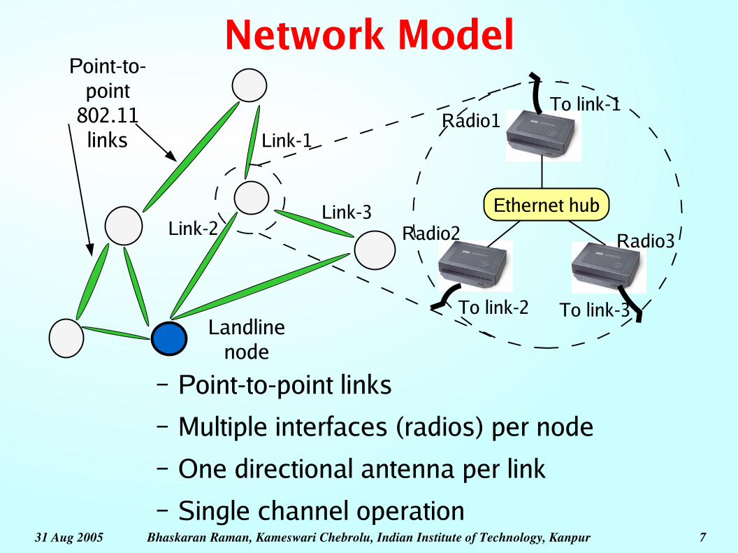
Network Model
– Point-to-point links– Multiple interfaces (radios) per node– One directional antenna per link– Single channel operation
To link-1
To link-2 To link-3
Ethernet hub
Link-1
Link-2Link-3
Point-to-point
802.11 links
Radio1
Radio2 Radio3
Landline node

31 Aug 2005 Bhaskaran Raman, Kameswari Chebrolu, Indian Institute of Technology, Kanpur 8
SynRx, SynTx, and Mix-Rx-Tx
Exposed interface problem within a node:CSMA/CA (802.11 DCF) inherently allows only one link operation per nodeProblems: (a) Immediate ACK, (2) CS back-off
N
A
B
T1
T2
R1
R2
(a) Syn-Rx
N
A
B
R1
R2
T1
T2
(b) Syn-Tx
N
A
B
R1
T2
T1
R2
(c) Mix-Rx-Tx

31 Aug 2005 Bhaskaran Raman, Kameswari Chebrolu, Indian Institute of Technology, Kanpur 9
SynOp: SynTx + SynRxExperimental Verification
=110o
A
B
N
8km0.9kmMandhana
Tower ht. = 40mMSSS (MS3)Tower ht. = 30m
BithoorTower ht. = 40m

31 Aug 2005 Bhaskaran Raman, Kameswari Chebrolu, Indian Institute of Technology, Kanpur 10
The 2P MAC Protocol● Two phases: each node switches between SynRx and SynTx● Topology has to be bipartite
A
BC
D
SynTxSynRx
SynTxSynRx
a) Links: A-->B, A-->D, C-->B, C-->D
b) Links: B-->A, B-->C, D-->A, D-->CNote: diagram ignores system and propogation delays
● How to achieve 2P on off-the-shelf hardware?● Can 2P work without tight time synchronization?● Relation between 2P and network topology● 2P performance versus CSMA/CA

31 Aug 2005 Bhaskaran Raman, Kameswari Chebrolu, Indian Institute of Technology, Kanpur 11
Achieving SynOp● Goal: bypass DCF to achieve SynOp● Two offending factors: immed. ACKs, CSMA backoff● Avoiding immediate ACKs:
– Use IBSS mode– IP unicast to/from MAC broadcast
● Avoiding CSMA backoff:– Make use of diversity
antenna– Change antsel_rx to the
unconnected antennabefore transmitting
PCMCIA/PCI card
RIGHT
LEFT
To external antenna
Unconnected SynTx: antsel_rx =RIGHTSynRx: antsel_rx =LEFT

31 Aug 2005 Bhaskaran Raman, Kameswari Chebrolu, Indian Institute of Technology, Kanpur 12
2P on a Single P2P Link– B bytes in each phase– SynTx+SynRx = one
round– Marker packet acts as a
“ token”– The two ends of the link
are in loose-synchrony– How do we handle:
● Temporary loss of synchrony?
● Link recovery or initialization?
SynTx
SynRx
InitSend pkts until
B bytes sent
B bytes sent,
send marker pktMarker pkt recd.,
or timeout
Wait for
marker pkt
31 Aug 2005 Bhaskaran Raman, Kameswari Chebrolu, Indian Institute of Technology, Kanpur 13
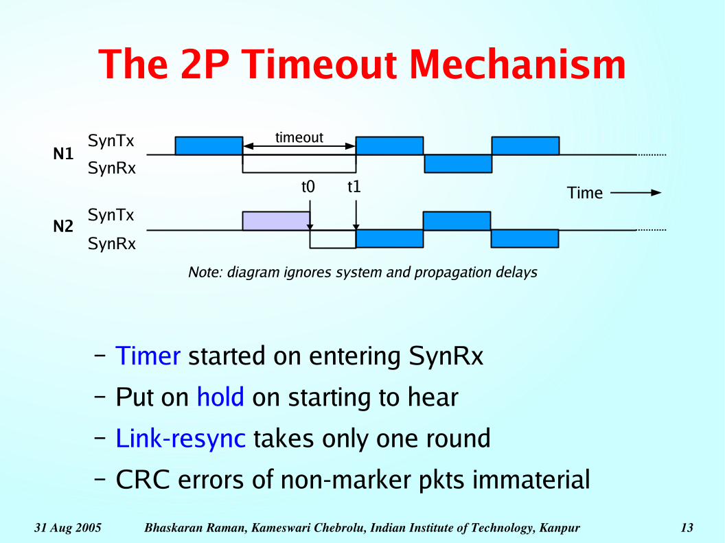
The 2P Timeout Mechanism
– Timer started on entering SynRx– Put on hold on starting to hear– Link-resync takes only one round– CRC errors of non-marker pkts immaterial
SynTx
SynRx
Note: diagram ignores system and propagation delays
timeout
Time
N1
N2
t1t0
SynTx
SynRx
31 Aug 2005 Bhaskaran Raman, Kameswari Chebrolu, Indian Institute of Technology, Kanpur 14
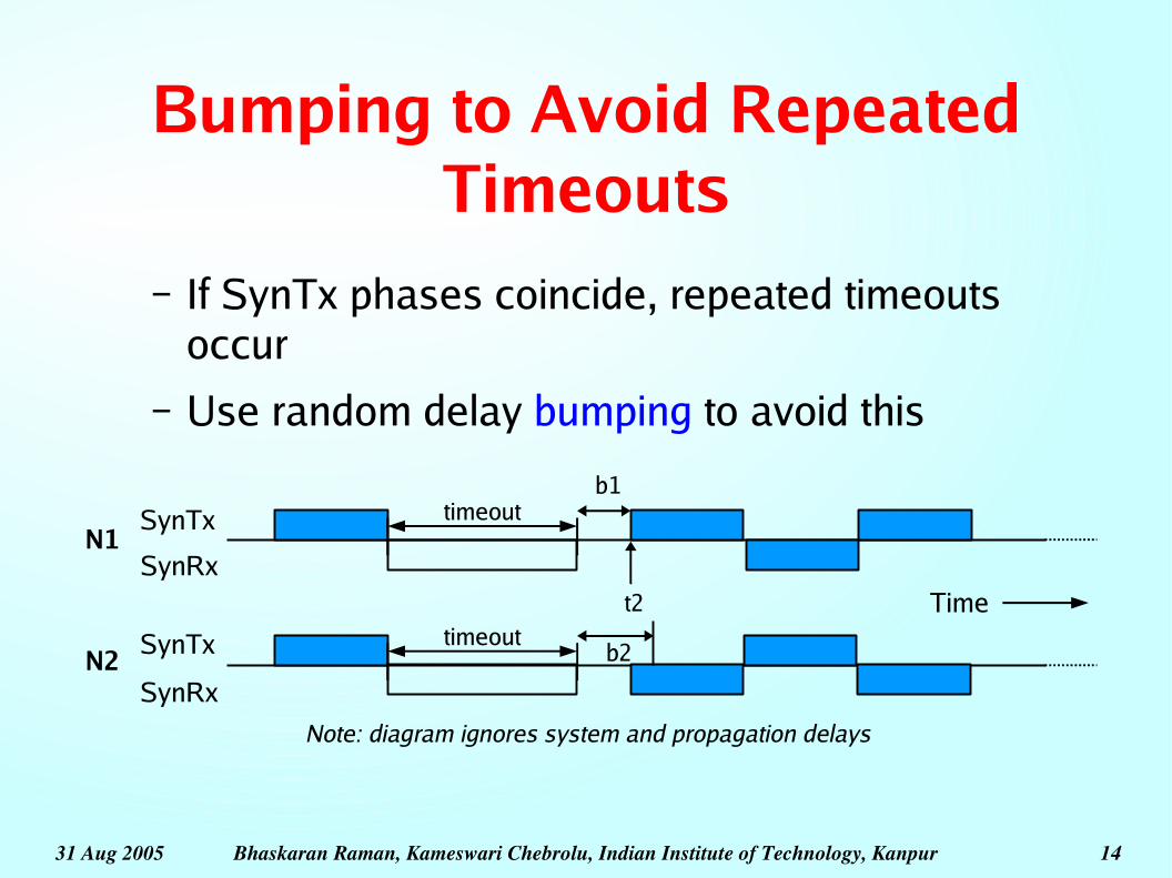
Bumping to Avoid Repeated Timeouts
– If SynTx phases coincide, repeated timeouts occur
– Use random delay bumping to avoid this
SynTx
SynRx
timeout
Time
N1
N2
SynTx
SynRx
timeoutt2
b1
b2
Note: diagram ignores system and propagation delays

31 Aug 2005 Bhaskaran Raman, Kameswari Chebrolu, Indian Institute of Technology, Kanpur 15
Communication Across Interface-Neighbours
– NOTIF msgs to indicate end of SynRx
– Wait for NOTIF msgs from all ifa-nbrs before SynTx
– UP/DOWN state w.r.t. each ifa-nbr
– Communication through shared-memory, or ethernet
SynTx
SynRx
InitSend pkts until
B bytes sent
B bytes sent,
send marker pktMarker pkt recd.,
or timeout
Wait for
marker pkt
Waitingto switch
Send NOTIF to all
ifa-nbrs
Wait for NOTIFs
Recv. NOTIFs from
all UP ifa-nbrs, or timeout

31 Aug 2005 Bhaskaran Raman, Kameswari Chebrolu, Indian Institute of Technology, Kanpur 16
Topology Constraints
● 2P has two main constraints:– Topology should be bipartite– Power constraints
● Write a set of linearequations withvariables P
i
– SIR >= SIRreqd
● Simple set of heuristicsfor topology formation
a j
ai
Overall gain from a i to a j=
(Gain of ai ' s Tx in a j ' s dirn)× (Gain of a j ' s Rx in ai ' s dirn)=Gain at angle×Gain at angle

31 Aug 2005 Bhaskaran Raman, Kameswari Chebrolu, Indian Institute of Technology, Kanpur 17
Evaluation of 2P
● Topology formation● Simulation studies● Implementation

31 Aug 2005 Bhaskaran Raman, Kameswari Chebrolu, Indian Institute of Technology, Kanpur 18
Evaluation of Topology Creation
● Aspects of interest:– How well does the algorithm scale?
– How much head-room in SIRreqd
is possible?
● Evaluation:– Using parts of the map of Durg district,
Chattisgarh, India– Using random topologies

31 Aug 2005 Bhaskaran Raman, Kameswari Chebrolu, Indian Institute of Technology, Kanpur 19
Topology Creation on Durg District
● Four clusters of villages
– Qi (i=1..4) 31, 32, 32, and 32 villages each
14 15 16 17 18 19 200
4
8
12
16
20
24
28
32
Q1 Q2 Q3 Q4
SIR_reqd (dB)
# lin
ks fo
rmed SIR
reqd of 18-20dB
easily possible

31 Aug 2005 Bhaskaran Raman, Kameswari Chebrolu, Indian Institute of Technology, Kanpur 20
The Topology on
Q1

31 Aug 2005 Bhaskaran Raman, Kameswari Chebrolu, Indian Institute of Technology, Kanpur 21
Simulation-based Evaluation
● ns-2 modification● Parameters:
– Q1's 31-node topology used
– UDP or TCP traffic● Packet size: 1400 bytes● UDP: saturating CBR traffic (every 2ms)● TCP: NewReno used
– Simulated time duration: 10sec

31 Aug 2005 Bhaskaran Raman, Kameswari Chebrolu, Indian Institute of Technology, Kanpur 22
Saturation Throughput (UDP)
The difference is due to SynOp

31 Aug 2005 Bhaskaran Raman, Kameswari Chebrolu, Indian Institute of Technology, Kanpur 23
TCP Performance
Very poor interaction between CSMA and TCP

31 Aug 2005 Bhaskaran Raman, Kameswari Chebrolu, Indian Institute of Technology, Kanpur 24
Implementation-based Evaluation
● Implementation using HostAP v0.2.4, Linux 2.4 (also works on Linux 2.6)
● 2P on a single link: 6.1Mbps– Less than the max. possible 6.5Mbps
– Overhead in antsel_rx, marker pkt, CWmin
being 32
● 2P performance on a pair of links:– A <--> N1, N2 <--> B, UDP traffic
2P 2.70 (0.31) 2.06 (0.24) 2.81 (0.15) 2.81 (0.10)
CSMA 2.07 (0.13) 1.13 (0.22) 1.90 (0.15) 3.11 (0.14)
Avg (SD) thrpt at A (Mbps)
Avg (SD) thrpt at N1 (Mbps)
Avg (SD) thrpt at N2 (Mbps)
Avg (SD) thrpt at B (Mbps)

Bhaskaran Raman, Kameswari Chebrolu, Indian Institute of Technology, Kanpur
Concluding Remarks
● Future directions:– Can be extended to P2MP scenarios as well
● Provided the antenna is suitable
– Topology creation is an interesting aspect of study
● 2P good for 802.11 mesh networks– Reuse of spectrum for max. throughput– Applicable in a wide-range of deployments
● Campus network, community network

Bhaskaran Raman, Kameswari Chebrolu, Indian Institute of Technology, Kanpur
Parameters in 2P● Phase duration: B bytes
– Large B implies lower % overhead, but higher latency
– For B=10KB, 6% overhead, 13ms latency– For B=4.5KB, 11% overhead, 6ms latency
● Timeout:– Lower bound: one phase duration– Simulation: 1.25 times the phase duration– Implementation: 25ms (kernel jitter ~ 10ms)

Bhaskaran Raman, Kameswari Chebrolu, Indian Institute of Technology, Kanpur
Some Remarks on 2P● Dummy bytes sent when no IP data
– Power consumption not a major concern– Embedded platform ~ 4-6W at least
802.11 radio ~ 0.1-0.2W only● Unequal phase durations possible
– But not really useful for more than a single hop network
● RF leakages: not too many interfaces can be placed close to each other

Bhaskaran Raman, Kameswari Chebrolu, Indian Institute of Technology, Kanpur
Power Constraints● Denote by P
i, the txpower at antenna A
i
● Each tx acts as interference to all other tx● Write a set of linear
equations withvariables Pi
– SIR >= SIRreqd
– Probably should havesome head-room too
– Feasibility of a solutionto this implies that thetopology is 2P-compatible
a j
ai
Overall gain from a i to a j=
(Gain of ai ' s Tx in a j ' s dirn)× (Gain of a j ' s Rx in ai ' s dirn)=Gain at angle×Gain at angle

Bhaskaran Raman, Kameswari Chebrolu, Indian Institute of Technology, Kanpur
Topology Formation● Tree topology:
– Trivially bipartite– Only one landline ==> tree is natural
● Only a tree is active at any time
● Heuristics:– H1: use short links– H2: avoid short angles between links– H3: minimize the number of hops
● Mimic a natural deployment pattern– Nodes close to landline connected first, then the
next level

Bhaskaran Raman, Kameswari Chebrolu, Indian Institute of Technology, Kanpur
Topology Creation on Random Scenarios
1 2 3 4 5 6 7 8 9 10 11 12 13 14 15 16 17 18 19 200
5
10
15
20
25
30
35
40
45
50
SIR_reqd=14dB SIR_reqd=16dB SIR_reqd=18dB
Topology number
# lin
ks fo
rmed
SIRreqd
of 16-18dB mostly possible for
up to 30-50 node topologies

Bhaskaran Raman, Kameswari Chebrolu, Indian Institute of Technology, Kanpur
Simulation-based Evaluation● TeNs:
– http://www.cse.iitk.ac.in/~bhaskar/tens/– Channel interference, grey regions, multiple
interface support, directional antennas● Further extensions:
– Populating the ARP table appropriately– 24dBi directional antenna support– MAC modifications: air propagation delay, ACK
timeout– LLC: sliding-window protocol

31 Aug 2005 Bhaskaran Raman, Kameswari Chebrolu, Indian Institute of Technology, Kanpur 32
Single Channel Operation
● 802.11b has only three independent channels● 802.11a has twelve independent channels
– Four are meant for outdoor use● Why only a single channel for the mesh?
– Mitigation of “ RF pollution”– The mesh may not be 3-edge-colourable– If the frequency is licensed, more channels could
imply more cost