Thank You | Steelway
24
MANUAL Core Products EXPERTS IN STEEL STEELWAY February 2019
Transcript of Thank You | Steelway

M A N U A L
Core Products
E X P E R T S I N S T E E L
STEELWAY
Core Products M a n u a l
February 2019

STEELWAY STEELWAYBrickhouse
STEELWAYFensecureE X P E R T S I N S T E E L
COMPANYSince 1928, Steelway Fensecure Ltd has continued to be the market leader in the field of fabrication excellence and expertise. We manufacture from our two state of the art production facilities, which are located in Wolverhampton and West Bromwich.
QUALITY ASSURANCE AND ACCREDITATIONTo meet and exceed the quality assurance expectations of our customers, Steelway are CE certified to execution class 3 and our operations are certified under PAS99, an Integrated Management System. PAS99 encompasses BS EN ISO 9001 - for Quality Management, BS EN ISO 14001 – for Environmental Management and OHSAS 18001 – for Health & Safety Management. We are accredited with UVDB & RISQS and due to the multitude of markets that we supply into, we are also committed to many other industry accreditation schemes, product certification and approvals, a full list is available on our website. Both our sites are certified to produce security products to varying levels in line with LPS1175.
CUSTOMER COMMITMENT AND SERVICEWe continually aim to provide a high level of customer service and are continually monitoring and developing our systems to meet with the expectations of our customer base. The understanding of professional Key Account Management and commitment to KPI requirements are a daily occurrence for our teams. We are committed to build and develop relationships in both the short and long term.
SUSTAINABILITYOur commitment to sustainable practises is paramount. Not only for the future of our own business, but to also support the goals and objectives of our customer base. From simple initiatives such as recycling and improvements in energy efficiency, sustainable solutions are also at the forefront of our minds during the early stages of any new product development. Reductions in material and scrappage, optimum utilisation of laser cut components, improvements in production efficiency, packaging, transportation and overall improvisation of the products life expectancy are taken into consideration.
DESIGN & EXPERTISEOur sales and design functions are equipped with the latest technology systems available. Utilising 3D CAD software, combined with communication and IT systems, we are able to provide our customers with a rapid response to enquiries and orders. Designing with 3D systems also allows for easy design verification prior to fabrication. We continue to invest in our design and fabrication facilities with plant, equipment, high speed automatic laser cutting equipment and software across both sites. Detailed structural design supported by full calculations if required.
PROJECT SOLUTIONS & SUPPORTUtilising our experienced sales teams, installation engineers and project managers we have the experience to take your product and project requirements from initial concept right through to commission. We welcome the opportunity to provide a complete package approach. This can include, design consultation and specification, site survey, quotation, design verification, manufacture, delivery, installation and final commissioning.
EXPERTS IN THE DESIGN,FABRICATION AND INSTALLATION OF HIGH QUALITY ENGINEERED METALWORK SOLUTIONS.E X P E R T S I N S T E E L
STEELWAY

Steelway Fensecure Ltd has been the market leader in the field of fabrication excellence and expertise since 1928. Our continued commitment to industry standards, specifications and design procedures gives customers confidence in Steelway to provide standard and engineered fabrication solutions.
Steelway offer our customers the assurance that all products supplied are of the highest quality, fully compliant with the relevant standards, codes of practice and building regulations. This is fully backed by our rigorous internal quality systems and factory production controls.
Architects, engineers and others now have the benefit of our experience brought together in this brochure of products engineered by Steelway. Guidance will readily be given by our Engineers for the specification and type of Steelway application most suitable for your project. This help is available from the outset when the initial plans are being drawn up. It will prove invaluable to the architect, Engineer and Draughtsman alike.
From design through to manufacture and installation, we work to the most exacting standards to provide quality products for the Water, Telecommunications and Power Utility Sectors as well as the Nuclear Sector, MOD, MOJ and other Government bodies, on projects where confidentiality is of the utmost importance.
Steelway are frequently requested to not only design, manufacture & supply our products, but also to assemble & carry out site installation. Our experienced teams of installation engineers undertake this work, controlled from our Wolverhampton works, we offer this service throughout the UK.
In the interest of quality and customer service, we pursue a policy of continuous product development and reserve the right to modify product designs without notice. Due to the limitations of space we have not been able to illustrate our complete product range. Please enquire if you do not find the products that fulfil your requirements - we may still be able to help you.
We offer:Free advice.Free Preliminary Surveys.*Free estimates and detailed quotations.Drawings for approval & structural calculations where applicable prior to manufacture on receipt of order.Full in-house manufacturing.On site assembly and installation service.*
* U.K. only.
At Steelway, we pride ourselves on customer service, on site support and our ability to produce quality fabrications either standard or bespoke that meet project requirements, timescales and budgets.
All information included is correct at date of publication.
Industrial Flooring . . . . . . . . . . . . . . . . . . 04 - 11
- Load Tables Diamond Pattern . . . . . 05 - 06
- Load Tables Rectangular Pattern . . . . 08 - 09
Ladders . . . . . . . . . . . . . . . . . . . . . . . . 12
Staircases & Platforms . . . . . . . . . . . . . . . 13
Treads . . . . . . . . . . . . . . . . . . . . . . . . . 14
Companionway Stair / Ship Type Ladder . 15
Spiral Stairs . . . . . . . . . . . . . . . . . . . . . 16
Handrails & Guardrails . . . . . . . . . . . . . . 17 - 20
GRP Products . . . . . . . . . . . . . . . . . . . . 21
STEELWAYQueensgate Works, Bilston Road,
Wolverhampton, West Midlands WV2 2NJ Tel: 01902 451733 Fax: 01902 452256
Email: [email protected] www.steelway.co.uk
E X P E R T S I N S T E E L
STEELWAY
03
04
Industrial Flooring - Open Type Flooring - Diamond Pattern
Key
1. “Steelway” mild steel diamond pattern openmesh flooring of all welded construction.
2. Straight bar (load bearing bars).
3. Pressed bar, acts as spacer and transmitslocalised loads to adjacent load-bearing bars.
4. Strong stich welded joints.
5. Nosing bar (binding bar) 5mm thick flat barwelded along the span edge of all panels. Nosingbars are not intended to be load bearing.
6. Every fourth or fifth straight bar and the edgebars are strongly welded to the nosing bars.
7. Installation marks are steel stamped in thecentre of nosing bars - see drawing below.
Available in: Mild Steel, Stainless Steel & Aluminium
7
Steelway Core Brochure To USE_Layout 1 17/04/2015 13:41 Page 5
04
Industrial Flooring - Diamond Pattern Open Mesh Flooring
Key
1. Steelway mild steel diamond pattern openmesh flooring of welded construction. 2. Straight bar (load bearing bars).
3. Pressed bar, acts as spacer and transmitslocalised loads to adjacent load-bearing bars.
4. Strong stitch welded joints.
5. Nosing bar (binding bar) 5mm thick flat barwelded along the span edge of all panels. Nosing bars are not intended to be load bearing.
6. Every fourth or fifth straight bar and the edgebars are strongly welded to the nosing bars.
7. Installation marks are steel stamped in thecentre of nosing bars - see drawing below.
8. Fully compliant self threading open meshflooring clips. Minimum four clips per panel.
Available in: Mild Steel (self-colour or hot dip galvanised), Stainless Steel & Aluminium
Span (direction straight or load bearing bars)
Pane
l wid
th u
p to
700
mm
. It is
, ho
weve
r, us
ual to
rest
rict w
idth
toob
tain
a p
anel
wei
ght n
ot e
xcee
ding
40k
g.Pr
efer
red
min
imum
wid
th 3
00m
m
Leng
th o
f wal
kway
or fl
oor a
rea
(178mm)
centre of welds
Correct (Right) Incorrect (Wrong)Ends of LoadBearing Bars arenot supported
Span or direction of Straight Bearing Bar (length of panel)
Width of panel
7
8
Steel stamped location on nosing bar (span edge of panel)
WeldedJoints
Self threading flooring clips

05
Safe Load Tables Diamond Pattern Mild Steel Open Mesh Flooring
Diamond Pattern Open Mesh Flooring
2
S a f e L o a d T a b l e s D i a m o n d P a t t e r n M i l d S t e e lF l o o r i n g
When using the load tables please consider the following notes:
1. Material grade S275JR, fy = 275N/mm² in accordance with BS EN 1993-1-1 (EC3).
2. Flooring panels simply supported.
3. The loads shown in the table are based upon the design strength divided by a partial safety factor, ϒQ = 1.5, allowance for the self weight of the flooring has been included.
4. Deflections limited to L/200, 10mm or 4mm* whichever is the lesser. * The difference in level between loaded and unloadedneighbouring panels has been limited to 4mm in accordance with BS EN ISO 14122-2:2001+A1:2010 & BS 4592-0:2006+A1:2012. Should the neighbouring panels be secured together the 4mm deflection rule need not apply and largerspans may be achievable, contact our sales team for further information.
5. Serrated load bearing bars to provide enhanced slip resistance are available upon request, contact our sales team for furtherinformation.
6. Steelway Diamond pattern flooring complies with clause 4.2.4.4 of BS EN ISO 14122-2:2001 and 5.1 of BS 4592-0:2006+A1:2012, where the maximum opening shall not permit the passage of a 35mm diameter sphere. Should the workingplatform be above a place where people are continuously working, as opposed to passing occasionally or on fire escapes then the maximum opening should not permit the passage of a 20mm diameter sphere and an alternative floor type / means of protection to prevent falling objects should be provided. For further information and advice please contact our sales team.
7. Values in red are below the required UDL or CL load requirements for general duty loading of table 1, BS 4592-0:2006+A1:2012.
8. U.D.L = Uniformly Distributed Load per square metreC.L = Concentrated load over 200mm x 200mm
When using the load tables please consider the following notes:
1. Material grade S275JR, fy = 275N/mm² in accordance with BS EN 1993-1-1 (EC3).
2. Flooring panels simply supported.
3. The loads shown in the table are based upon the design strength divided by a partial safety factor, γQ = 1.5,allowance for the self weight of the flooring has been included.
4. Deflections limited to L/200, 10mm or 4mm* whichever is the lesser. * The difference in level between loaded andunloaded neighbouring panels has been limited to 4mm in accordance with BS EN ISO14122-2:2016 & BS 4592-0:2006+A1:2012. Should the neighbouring panels be secured together the 4mm deflection rule need not apply and larger spans may be achievable, contact our sales team for further information.
5. Serrated load bearing bars to provide enhanced slip resistance are available upon request, contact our sales team forfurther information.
6. Steelway Diamond pattern flooring complies with clause 4.2.4.4 of BS EN ISO 14122-2:2016 and 5.1 of BS 4592-0:2006+A1:2012, where the maximum opening shall not permit the passage of a 35mm diameter sphere. Should the working platform be above a place where people are continuously working, as opposed to passing occasionally the maximum opening should not permit the passage of a 20mm diameter sphere and an alternative floor type / means of protection to prevent falling objects should be provided. For further information and advice please contact our sales team.
7. Values in red are below the required UDL or CL load requirements for general duty loading of table , 1 BS 4592-0:2006+A1:2012.
8. U.D.L = Uniformly Distributed Load per square metre C.L = Concentrated load over 200mm x 200mm
Leng
th o
f wal
kway
or fl
oor a
rea

06
4
Safe Load Tables Diamond Pattern Mild Steel FlooringConcentrated Loads
In addition to the notes on page 5, when using the load tables please consider the following notes:
1. The loads shown include a 25% increase to the characteristic static load allowing for the effects of impact as per table 1 of BS4592-0:2006+A1:2012.
2. Deflections limited to L/200, 10mm
3. Serrated load bearing bars (FLS) to provide enhanced slip resistance are available upon request, contact our sales team forfurther information.
4. Durbar solid top flooring (FLP) is available for enhanced load carrying capacities; contact our sales team for furtherinformation.
5. The load table below is based upon concentrated loads applied by slow moving road vehicles with pneumatic tyres. Wherecovers are subject to other types of usage e.g. Fork Lift trucks etc. a specific enquiry should be made.
6. Alternative concentrated load areas available on request.
C.L = Concentrated area load over 200mm x 200mm*
Safe Load Tables Diamond Pattern Mild Steel Open Mesh Flooring Concentrated LoadsIn addition to the notes on page 5 , when using the load tables please consider the following notes:
1. The loads shown include a 25% increase to the characteristic staticload allowing for the effects of impact as per table 1 of BS 4592-0:2006+A1:2012.
2. Deflections limited to L/200, 10mm
3. Serrated load bearing bars (FLS) to provide enhanced slip resistanceare available upon request, contact our sales team for further information.
4. Durbar solid top flooring (FLP) is available for enhanced loadcarrying capacities; contact our sales team for further information.
5. The load table below is based upon concentrated loads applied by slow moving road vehicles with pneumatic tyres.Where covers are subject to other types of usage e.g. Fork Lift trucks etc. a specific enquiry should be made.
6. Alternative concentrated load areas available on request.
C.L = Concentrated area load over 200mm x 200mm*
Wheel of Vehicle
Dimension Inside Trench
Applied Load Contact Area of Pneumatic Tyre
Correct (Right)
Incorrect (Wrong)Ends of LoadBearing Bars arenot supported
Width of panel
Span or direction of Straight Bearing Bar (lenth of panel)
07
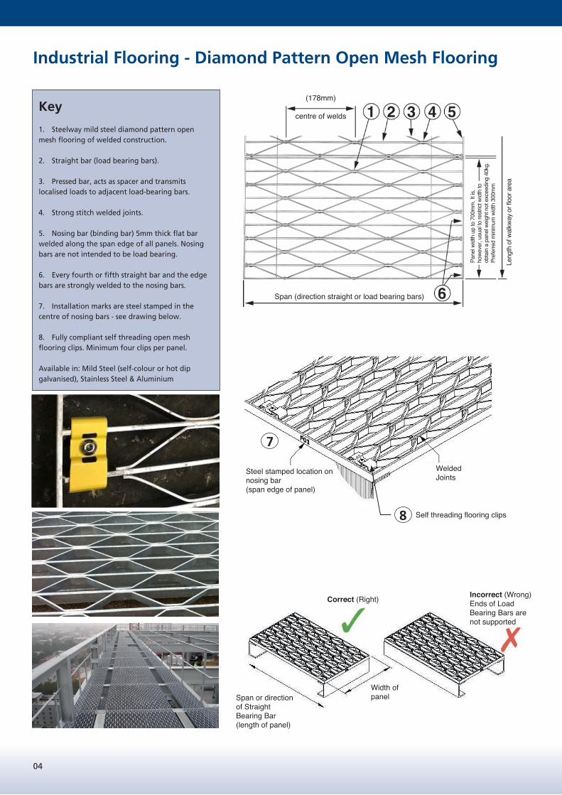
Rectangular Pattern Open Mesh Flooring
Stock PanelsThese can be supplied in nominal 6m lengthsby 1m wide.
Plain and Serrated Load Bearing BarsOur standard range of gratings with the special transverse twisted bar provide better than average slip resistance. Where oily or icy conditions are likely to be prevalent, then gratings with serrated edge load bearing bars can be supplied for improved grip.
FabricationYour specific requirements are undertaken after submission of our detailed drawings for your approval. Our proposals will provide you with the optimum layout taking account of all requirements for cut-outs, shaping and supporting steelwork. For ease of installation on site, each fabricated panel is hard stamped on the binding bar with an erection mark to correspond with our layout drawings.
Key
1. Load bearing bars (Straight bars).
2. Tranverse twisted bars.
3. Nosing Bar (Binding bar) to be weldedperpendicular to every fourth or fifth load bearingbar. Nosing bars are not intended to be loadbearing. Bars shall be of equal thickness to thethickness of the load bearing bars and shall be flushwith the top of the load bearing bars.
4. Fully compliant self threading open meshflooring clip. Minimum four number clips per panel.
5. Load bearing bars must be supported at eachend by a minimum of 25mm.
6. Transverse twisted bar centresGenerally 50 or 100.
7. Load bearing bar centres.Generally 23, 30, 34 or 41
Available in Mild Steel (self-colour or hot dip galvanised), & Stainless Steel
Effective span (clear span between supports)
Span (direction straight or load bearing bars)
Pane
l wid
th u
pto
1000
mm
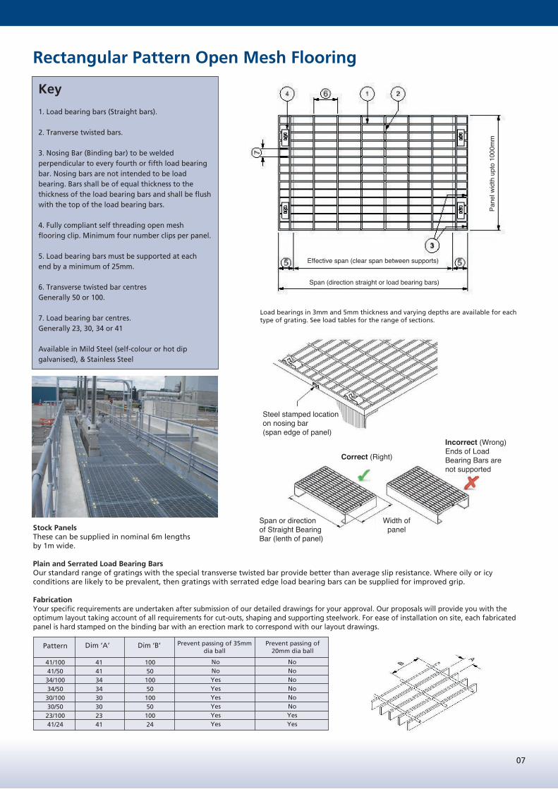
41/10041/5034/10034/5030/10030/5023/10041/24
Pattern Dim ‘A’ Dim ‘B’ Prevent passing of 35mm dia ball
Prevent passing of 20mm dia ball
4141343430302341
10050100501005010024
NoNoYesYesYesYesYesYes
NoNoNoNoNoNoYesYes
Steel stamped location on nosing bar(span edge of panel)
Load bearings in 3mm and 5mm thickness and varying depths are available for each type of grating. See load tables for the range of sections.
08
Saf e L oa d Ta bl es Recta ngula r P a tt ern Mi l d Ste el F l oor i ng
When using the load tables please consider the following notes:
1. Material grade S275JR, fy = 275N/mm² in accordance with BS EN 1993-1-1 (EC3).
2. Flooring panels simply supported.
3. The loads shown in the table are based upon the design strength divided by a partial safety factor, ϒQ = 1.5, allowance for the self weightof the flooring has been included.
4. Deflections limited to L/200, 10mm or 4mm* whichever is the lesser. * The difference in level between loaded and unloadedneighbouring panels has been limited to 4mm in accordance with BS EN ISO 14122-2:2001+A1:2010 & BS 4592-0:2006+A1:2012. Shouldthe neighbouring panels be secured together the 4mm deflection rule need not apply and larger spans may be achievable, contact oursales team for further information.
5. Serrated load bearing bars to provide enhanced slip resistance are available upon request, contact our sales team for furtherinformation.
6. All floor types with the exception of the 41mm pattern comply with clause 4.2.4.4 of BS EN ISO 14122-2:2001 and 5.1 of BS 4592-0:2006+A1:2012, where the maximum opening shall not permit the passage of a 35mm diameter sphere. Should the working platformbe above a place where people are continuously working, as opposed to passing occasionally or on fire escapes then the maximumopening should not permit the passage of a 20mm diameter sphere and an alternative floor type / means of protection to prevent fallingobjects should be provided. For further information and advice please contact our sales team.
7. Values in red are below the required UDL or CL load requirements for general duty loading of table 1, BS 4592-0:2006+A1:2012.
8. U.D.L = Uniformly Distributed Load per square metre, kN/m².C.L = Concentrated load over 200mm x 200mm, kN.
Rectangular Pattern Type 34/100
600 750 900 1050 1200 1350 1500 1650 1800 1950 2100 2250 2400
U.D.L 22.40 11.47 5.90 3.18 1.87 1.17 0.76 0.52 0.37 0.27 0.20 0.15 0.12 938
C.L 2.07 1.30 0.79 0.50 0.33 0.23 0.17 0.13 0.10 0.08 0.06 0.05 0.04 686
U.D.L 43.75 22.40 11.52 6.22 3.65 2.28 1.49 1.02 0.72 0.52 0.39 0.29 0.23 1109
C.L 4.03 2.53 1.55 0.97 0.65 0.45 0.33 0.25 0.19 0.15 0.12 0.10 0.08 902
U.D.L 72.92 37.33 19.20 10.37 6.08 3.79 2.49 1.70 1.20 0.87 0.65 0.49 0.38 1260
C.L 6.72 4.22 2.58 1.62 1.08 0.75 0.55 0.41 0.32 0.25 0.20 0.16 0.13 1069
U.D.L 75.60 38.71 19.91 10.75 6.30 3.93 2.58 1.76 1.24 0.90 0.67 0.51 0.39 1271
C.L 6.91 4.38 2.68 1.67 1.12 0.78 0.57 0.43 0.33 0.26 0.21 0.17 0.14 1082
U.D.L 126.00 64.51 33.19 17.91 10.50 6.56 4.30 2.94 2.07 1.51 1.12 0.85 0.66 1445
C.L 11.52 7.30 4.46 2.79 1.86 1.30 0.95 0.71 0.55 0.43 0.34 0.28 0.23 1283
U.D.L 112.09 61.47 31.62 17.07 10.00 6.25 4.10 2.80 1.98 1.43 1.07 0.81 0.63 1427
C.L 9.41 6.95 4.25 2.66 1.77 1.24 0.90 0.68 0.52 0.41 0.33 0.27 0.22 1263
U.D.L 186.84 102.44 52.70 28.44 16.67 10.41 6.83 4.66 3.29 2.39 1.78 1.35 1.04 1622
C.L 15.68 11.59 7.08 4.43 2.96 2.07 1.51 1.13 0.87 0.68 0.55 0.44 0.37 1497
U.D.L 146.44 91.75 47.20 25.48 14.93 9.32 6.12 4.18 2.95 2.14 1.59 1.21 0.93 1578
C.L 12.29 9.44 6.34 3.97 2.65 1.86 1.35 1.01 0.78 0.61 0.49 0.40 0.33 1443
U.D.L 244.08 152.92 78.66 42.46 24.89 15.54 10.19 6.96 4.92 3.57 2.65 2.01 1.56 1792
C.L 20.49 15.74 10.57 6.62 4.41 3.09 2.25 1.69 1.30 1.02 0.82 0.66 0.55 1711
U.D.L 381.50 244.00 153.64 82.93 48.61 30.35 19.91 13.60 9.60 6.97 5.18 3.93 3.04 2119
C.L 32.03 24.61 19.97 12.92 8.62 6.04 4.39 3.30 2.54 1.99 1.59 1.30 1.07 2138
U.D.L 549.47 351.47 243.91 143.30 84.00 52.44 34.41 23.50 16.59 12.05 8.96 6.80 5.25 2429
C.L 46.14 35.46 28.78 22.33 14.90 10.43 7.59 5.70 4.38 3.44 2.76 2.24 1.84 2566
Load bearing
bars (mm)
25 x 3 34/100 20.20
20 x 3
Mass
kg/m2
34/100 16.67
Type
25 x 5 34/100 31.81
30 x 3 34/100 23.74
30.80
30 x 5 34/100 37.70
35 x 3 34/100 27.27
Max'm
span (mm)
for 1.5 kN
60 x 5 34/100 73.03
Load
type
40 x 5 34/100 49.48
50 x 5 34/100 61.25
35 x 5 34/100 43.59
40 x 3 34/100
Max'm
span (mm)
for 5 kN/m2
Clear span (mm)
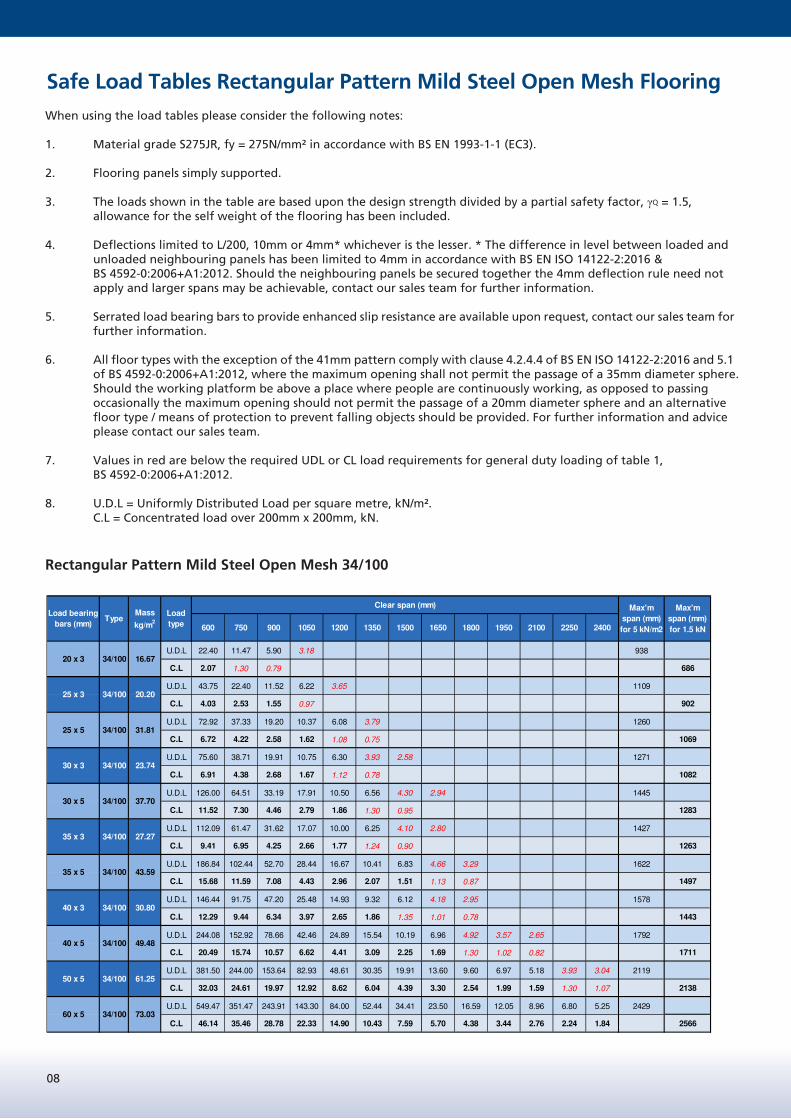
Safe Load Tables Rectangular Pattern Mild Steel Open Mesh Flooring
When using the load tables please consider the following notes:
1. Material grade S275JR, fy = 275N/mm² in accordance with BS EN 1993-1-1 (EC3).
2. Flooring panels simply supported.
3. The loads shown in the table are based upon the design strength divided by a partial safety factor, γQ = 1.5,allowance for the self weight of the flooring has been included.
4. Deflections limited to L/200, 10mm or 4mm* whichever is the lesser. * The difference in level between loaded and unloaded neighbouring panels has been limited to 4mm in accordance with BS EN ISO 14122-2:2016 &
BS 4592-0:2006+A1:2012. Should the neighbouring panels be secured together the 4mm deflection rule need not apply and larger spans may be achievable, contact our sales team for further information.
5. Serrated load bearing bars to provide enhanced slip resistance are available upon request, contact our sales team forfurther information.
6. All floor types with the exception of the 41mm pattern comply with clause 4.2.4.4 of BS EN ISO 14122-2:2016 and 5.1 of BS 4592-0:2006+A1:2012, where the maximum opening shall not permit the passage of a 35mm diameter sphere.
Should the working platform be above a place where people are continuously working, as opposed to passing occasionally the maximum opening should not permit the passage of a 20mm diameter sphere and an alternative
floor type / means of protection to prevent falling objects should be provided. For further information and advice please contact our sales team.
7. Values in red are below the required UDL or CL load requirements for general duty loading of table 1, BS 4592-0:2006+A1:2012.
8. U.D.L = Uniformly Distributed Load per square metre, kN/m². C.L = Concentrated load over 200mm x 200mm, kN.
Rectangular Pattern Mild Steel Open Mesh 34/100

09
* For mass Type 30/50 add 2.8 kg/m2
* For mass Type 30/50 add 2.8 kg/m2
Rectangular Pattern Type 30/100 and 30/50
600 750 900 1050 1200 1350 1500 1650 1800 1950 2100 2250 2400
U.D.L 25.39 13.00 6.69 3.61 2.12 1.32 0.87 0.59 0.42 0.30 0.23 0.17 0.13 968
C.L 2.36 1.48 0.91 0.57 0.38 0.27 0.19 0.14 0.11 0.09 0.07 0.06 0.05 733
U.D.L 49.58 25.39 13.06 7.05 4.13 2.58 1.69 1.16 0.82 0.59 0.44 0.33 0.26 1144
C.L 4.61 2.90 1.77 1.11 0.74 0.52 0.38 0.28 0.22 0.17 0.14 0.11 0.09 943
U.D.L 82.64 42.31 21.76 11.75 6.89 4.30 2.82 1.93 1.36 0.99 0.73 0.56 0.43 1300
C.L 7.68 4.83 2.95 1.85 1.23 0.86 0.63 0.47 0.36 0.28 0.23 0.19 0.15 1118
U.D.L 85.68 43.87 22.57 12.18 7.14 4.46 2.92 2.00 1.41 1.02 0.76 0.58 0.45 1312
C.L 7.90 5.00 3.06 1.91 1.28 0.89 0.65 0.49 0.38 0.30 0.24 0.19 0.16 1131
U.D.L 142.80 73.11 37.61 20.30 11.90 7.43 4.87 3.33 2.35 1.71 1.27 0.96 0.74 1490
C.L 13.16 8.34 5.10 3.19 2.13 1.49 1.08 0.81 0.63 0.49 0.39 0.32 0.26 1341
U.D.L 127.04 69.66 35.83 19.34 11.34 7.08 4.64 3.17 2.24 1.63 1.21 0.92 0.71 1473
C.L 10.75 7.95 4.86 3.04 2.03 1.42 1.03 0.78 0.60 0.47 0.37 0.30 0.25 1320
U.D.L 211.75 116.10 59.72 32.24 18.90 11.80 7.74 5.29 3.73 2.71 2.01 1.53 1.18 1673
C.L 17.92 13.24 8.09 5.07 3.38 2.37 1.72 1.29 0.99 0.78 0.62 0.51 0.42 1565
U.D.L 165.97 103.98 53.49 28.87 16.92 10.57 6.93 4.73 3.34 2.43 1.80 1.37 1.06 1628
C.L 14.05 10.79 7.25 4.54 3.03 2.12 1.54 1.16 0.89 0.70 0.56 0.45 0.37 1509
U.D.L 276.63 173.31 89.15 48.12 28.21 17.61 11.55 7.89 5.57 4.05 3.01 2.28 1.76 1849
C.L 23.42 17.99 12.08 7.56 5.04 3.53 2.57 1.93 1.48 1.17 0.93 0.76 0.62 1789
U.D.L 432.37 276.54 174.12 93.99 55.09 34.39 22.57 15.41 10.88 7.90 5.87 4.46 3.44 2186
C.L 36.61 28.13 22.83 14.77 9.85 6.90 5.02 3.77 2.90 2.28 1.82 1.48 1.22 2236
U.D.L 622.73 398.33 276.44 162.41 95.20 59.43 38.99 26.63 18.80 13.65 10.15 7.70 5.95 2507
C.L 52.73 40.53 32.89 25.52 17.03 11.93 8.68 6.51 5.01 3.94 3.15 2.56 2.11 2683
Load bearing
bars (mm)
25 x 3 30/100 22.54
20 x 3
Mass
kg/m2
30/100 18.53
Type
25 x 5 30/100 35.69
30 x 3 30/100 26.54
34.55
30 x 5 30/100 42.37
35 x 3 30/100 30.54
Max'm
span (mm)
for 1.5 kN
60 x 5 30/100 82.40
Load
type
40 x 5 30/100 55.71
50 x 5 30/100 69.06
35 x 5 30/100 49.04
40 x 3 30/100
Max'm
span (mm)
for 5 kN/m2
Clear span (mm)
Rectangular Pattern Type 41/100 and 40/50
600 750 900 1050 1200 1350 1500 1650 1800 1950 2100 2250 2400
U.D.L 18.67 9.56 4.92 2.65 1.56 0.97 0.64 0.44 0.31 0.22 0.17 0.13 0.10 896
C.L 1.77 1.11 0.68 0.43 0.28 0.20 0.14 0.11 0.08 0.07 0.05 0.04 0.04 635
U.D.L 36.46 18.67 9.60 5.18 3.04 1.90 1.24 0.85 0.60 0.44 0.32 0.25 0.19 1059
C.L 3.46 2.17 1.33 0.83 0.55 0.39 0.28 0.21 0.16 0.13 0.10 0.08 0.07 857
U.D.L 60.76 31.11 16.00 8.64 5.06 3.16 2.07 1.42 1.00 0.73 0.54 0.41 0.32 1204
C.L 5.76 3.62 2.21 1.38 0.92 0.65 0.47 0.35 0.27 0.21 0.17 0.14 0.11 1016
U.D.L 63.00 32.26 16.59 8.96 5.25 3.28 2.15 1.47 1.04 0.75 0.56 0.42 0.33 1215
C.L 5.92 3.75 2.29 1.44 0.96 0.67 0.49 0.37 0.28 0.22 0.18 0.14 0.12 1028
U.D.L 105.00 53.76 27.65 14.93 8.75 5.46 3.58 2.45 1.73 1.25 0.93 0.71 0.55 1380
C.L 9.87 6.26 3.82 2.39 1.60 1.12 0.81 0.61 0.47 0.37 0.30 0.24 0.20 1219
U.D.L 93.41 51.22 26.35 14.22 8.34 5.20 3.41 2.33 1.65 1.20 0.89 0.67 0.52 1364
C.L 8.06 5.96 3.64 2.28 1.52 1.07 0.77 0.58 0.45 0.35 0.28 0.23 0.19 1199
U.D.L 155.69 85.37 43.91 23.70 13.89 8.67 5.69 3.89 2.74 1.99 1.48 1.12 0.87 1549
C.L 13.44 9.93 6.07 3.80 2.53 1.78 1.29 0.97 0.75 0.59 0.47 0.38 0.31 1422
U.D.L 122.03 76.46 39.33 21.23 12.44 7.77 5.10 3.48 2.46 1.78 1.33 1.01 0.78 1507
C.L 10.54 8.09 5.44 3.40 2.27 1.59 1.16 0.87 0.67 0.52 0.42 0.34 0.28 1371
U.D.L 203.40 127.43 65.55 35.38 20.74 12.95 8.50 5.80 4.10 2.97 2.21 1.68 1.30 1713
C.L 17.56 13.49 9.06 5.67 3.78 2.65 1.93 1.45 1.11 0.87 0.70 0.57 0.47 1625
U.D.L 317.91 203.33 128.03 69.11 40.51 25.29 16.59 11.33 8.00 5.81 4.32 3.28 2.53 2025
C.L 27.46 21.10 17.12 11.08 7.39 5.18 3.77 2.83 2.17 1.71 1.37 1.11 0.91 2031
U.D.L 457.89 292.89 203.26 119.42 70.00 43.70 28.67 19.58 13.83 10.04 7.46 5.66 4.38 2321
C.L 39.55 30.39 24.67 19.14 12.77 8.94 6.51 4.88 3.76 2.95 2.36 1.92 1.58 2437
Max'm
span (mm)
for 5 kN/m2
Clear span (mm) Max'm
span (mm)
for 1.5 kN
60 x 5 41/100 61.32
Load
type
40 x 5 41/100 41.69
50 x 5 41/100 51.50
35 x 5 41/100 36.79
40 x 3 41/100 26.13
30 x 5 41/100 31.88
35 x 3 41/100 23.18
25 x 5 41/100 26.97
30 x 3 41/100 20.24
Load bearing
bars (mm)
25 x 3 41/100 17.30
20 x 3
Mass
kg/m2
41/100 14.35
Type
* For mass Type 30/50 add 2.8 kg/m2
* For mass Type 30/50 add 2.8 kg/m2
Rectangular Pattern Type 30/100 and 30/50
600 750 900 1050 1200 1350 1500 1650 1800 1950 2100 2250 2400
U.D.L 25.39 13.00 6.69 3.61 2.12 1.32 0.87 0.59 0.42 0.30 0.23 0.17 0.13 968
C.L 2.36 1.48 0.91 0.57 0.38 0.27 0.19 0.14 0.11 0.09 0.07 0.06 0.05 733
U.D.L 49.58 25.39 13.06 7.05 4.13 2.58 1.69 1.16 0.82 0.59 0.44 0.33 0.26 1144
C.L 4.61 2.90 1.77 1.11 0.74 0.52 0.38 0.28 0.22 0.17 0.14 0.11 0.09 943
U.D.L 82.64 42.31 21.76 11.75 6.89 4.30 2.82 1.93 1.36 0.99 0.73 0.56 0.43 1300
C.L 7.68 4.83 2.95 1.85 1.23 0.86 0.63 0.47 0.36 0.28 0.23 0.19 0.15 1118
U.D.L 85.68 43.87 22.57 12.18 7.14 4.46 2.92 2.00 1.41 1.02 0.76 0.58 0.45 1312
C.L 7.90 5.00 3.06 1.91 1.28 0.89 0.65 0.49 0.38 0.30 0.24 0.19 0.16 1131
U.D.L 142.80 73.11 37.61 20.30 11.90 7.43 4.87 3.33 2.35 1.71 1.27 0.96 0.74 1490
C.L 13.16 8.34 5.10 3.19 2.13 1.49 1.08 0.81 0.63 0.49 0.39 0.32 0.26 1341
U.D.L 127.04 69.66 35.83 19.34 11.34 7.08 4.64 3.17 2.24 1.63 1.21 0.92 0.71 1473
C.L 10.75 7.95 4.86 3.04 2.03 1.42 1.03 0.78 0.60 0.47 0.37 0.30 0.25 1320
U.D.L 211.75 116.10 59.72 32.24 18.90 11.80 7.74 5.29 3.73 2.71 2.01 1.53 1.18 1673
C.L 17.92 13.24 8.09 5.07 3.38 2.37 1.72 1.29 0.99 0.78 0.62 0.51 0.42 1565
U.D.L 165.97 103.98 53.49 28.87 16.92 10.57 6.93 4.73 3.34 2.43 1.80 1.37 1.06 1628
C.L 14.05 10.79 7.25 4.54 3.03 2.12 1.54 1.16 0.89 0.70 0.56 0.45 0.37 1509
U.D.L 276.63 173.31 89.15 48.12 28.21 17.61 11.55 7.89 5.57 4.05 3.01 2.28 1.76 1849
C.L 23.42 17.99 12.08 7.56 5.04 3.53 2.57 1.93 1.48 1.17 0.93 0.76 0.62 1789
U.D.L 432.37 276.54 174.12 93.99 55.09 34.39 22.57 15.41 10.88 7.90 5.87 4.46 3.44 2186
C.L 36.61 28.13 22.83 14.77 9.85 6.90 5.02 3.77 2.90 2.28 1.82 1.48 1.22 2236
U.D.L 622.73 398.33 276.44 162.41 95.20 59.43 38.99 26.63 18.80 13.65 10.15 7.70 5.95 2507
C.L 52.73 40.53 32.89 25.52 17.03 11.93 8.68 6.51 5.01 3.94 3.15 2.56 2.11 2683
Load bearing
bars (mm)
25 x 3 30/100 22.54
20 x 3
Mass
kg/m2
30/100 18.53
Type
25 x 5 30/100 35.69
30 x 3 30/100 26.54
34.55
30 x 5 30/100 42.37
35 x 3 30/100 30.54
Max'm
span (mm)
for 1.5 kN
60 x 5 30/100 82.40
Load
type
40 x 5 30/100 55.71
50 x 5 30/100 69.06
35 x 5 30/100 49.04
40 x 3 30/100
Max'm
span (mm)
for 5 kN/m2
Clear span (mm)
Rectangular Pattern Type 41/100 and 40/50
600 750 900 1050 1200 1350 1500 1650 1800 1950 2100 2250 2400
U.D.L 18.67 9.56 4.92 2.65 1.56 0.97 0.64 0.44 0.31 0.22 0.17 0.13 0.10 896
C.L 1.77 1.11 0.68 0.43 0.28 0.20 0.14 0.11 0.08 0.07 0.05 0.04 0.04 635
U.D.L 36.46 18.67 9.60 5.18 3.04 1.90 1.24 0.85 0.60 0.44 0.32 0.25 0.19 1059
C.L 3.46 2.17 1.33 0.83 0.55 0.39 0.28 0.21 0.16 0.13 0.10 0.08 0.07 857
U.D.L 60.76 31.11 16.00 8.64 5.06 3.16 2.07 1.42 1.00 0.73 0.54 0.41 0.32 1204
C.L 5.76 3.62 2.21 1.38 0.92 0.65 0.47 0.35 0.27 0.21 0.17 0.14 0.11 1016
U.D.L 63.00 32.26 16.59 8.96 5.25 3.28 2.15 1.47 1.04 0.75 0.56 0.42 0.33 1215
C.L 5.92 3.75 2.29 1.44 0.96 0.67 0.49 0.37 0.28 0.22 0.18 0.14 0.12 1028
U.D.L 105.00 53.76 27.65 14.93 8.75 5.46 3.58 2.45 1.73 1.25 0.93 0.71 0.55 1380
C.L 9.87 6.26 3.82 2.39 1.60 1.12 0.81 0.61 0.47 0.37 0.30 0.24 0.20 1219
U.D.L 93.41 51.22 26.35 14.22 8.34 5.20 3.41 2.33 1.65 1.20 0.89 0.67 0.52 1364
C.L 8.06 5.96 3.64 2.28 1.52 1.07 0.77 0.58 0.45 0.35 0.28 0.23 0.19 1199
U.D.L 155.69 85.37 43.91 23.70 13.89 8.67 5.69 3.89 2.74 1.99 1.48 1.12 0.87 1549
C.L 13.44 9.93 6.07 3.80 2.53 1.78 1.29 0.97 0.75 0.59 0.47 0.38 0.31 1422
U.D.L 122.03 76.46 39.33 21.23 12.44 7.77 5.10 3.48 2.46 1.78 1.33 1.01 0.78 1507
C.L 10.54 8.09 5.44 3.40 2.27 1.59 1.16 0.87 0.67 0.52 0.42 0.34 0.28 1371
U.D.L 203.40 127.43 65.55 35.38 20.74 12.95 8.50 5.80 4.10 2.97 2.21 1.68 1.30 1713
C.L 17.56 13.49 9.06 5.67 3.78 2.65 1.93 1.45 1.11 0.87 0.70 0.57 0.47 1625
U.D.L 317.91 203.33 128.03 69.11 40.51 25.29 16.59 11.33 8.00 5.81 4.32 3.28 2.53 2025
C.L 27.46 21.10 17.12 11.08 7.39 5.18 3.77 2.83 2.17 1.71 1.37 1.11 0.91 2031
U.D.L 457.89 292.89 203.26 119.42 70.00 43.70 28.67 19.58 13.83 10.04 7.46 5.66 4.38 2321
C.L 39.55 30.39 24.67 19.14 12.77 8.94 6.51 4.88 3.76 2.95 2.36 1.92 1.58 2437
Max'm
span (mm)
for 5 kN/m2
Clear span (mm) Max'm
span (mm)
for 1.5 kN
60 x 5 41/100 61.32
Load
type
40 x 5 41/100 41.69
50 x 5 41/100 51.50
35 x 5 41/100 36.79
40 x 3 41/100 26.13
30 x 5 41/100 31.88
35 x 3 41/100 23.18
25 x 5 41/100 26.97
30 x 3 41/100 20.24
Load bearing
bars (mm)
25 x 3 41/100 17.30
20 x 3
Mass
kg/m2
41/100 14.35
Type
Rectangular Pattern Mild Steel Open Mesh Flooring 30/100 and 30/50
Rectangular Pattern Mild Steel Open Mesh Flooring 41/100 and 41/50
* For mass Type 30/50 add 2.8 kg/m2
* For mass Type 41/50 add 2.8kg/m2

10
‘FLS’Steelway ‘FLS’ serrated flooring. Pressed spacer bars have a serrated edge providing extra grip for the user on the walking surface. Serrated flooring, apart from the serrated surface, is supplied in panels of similar specification to our standards ‘FL’ flooring.
‘FLP’‘FLP’ flooring has a solid surface of Durbar pattern plate or alternatively plain surface plate as preferred, welded to the top face of open mesh flooring. ‘FLP’ covers may be used alongside open mesh of matching depth, without a trip, to provide a virtually closed floor area over machinery or other sensitive equipment, whilst retaining the advantage of open mesh flooring in other areas. This type of cover also provides better distribution of highly concentrated point loads across a panel without the usual distortion.
Covers can be supplied in a range of depths. For particularly slippery conditions a carborundum surface finish for solid covers is available.‘FLP’ floor covers and open mesh flooring panels have been used extensively for raised flooring systems, thus allowing easy access to services below should the need arise.
Example: FLP 30 is 25mm open mesh +4.5mm plate cover.
FLP FLOORINGwith integral solid floor plate.
FLS OPEN FLOORINGwith serrated edge.
Mild Steel Angle Curb
For straight runs of duct we supply standard 3m lengths of curb.
Make-up lengths are provided to obtain the correct overall length, these are marked for identification on site. Each angle curb is provided with joint plates and countersunk bolts to assist installation on site. Lugs are welded on at approximately 900mm centres and at approximately 150mm from each end. It is preferable, though not essential, for customers to provide a layout showing all ducts where it is proposed to have floor covers and curbing: this will allow us to provide you with drawings for your approval showing the most economical arrangement.
- Available in mild steel, aluminium or stainless steel.
ANGLE CURBING ‘FLC’ FORSTEELWAY OPEN TYPE FLOORINGIN STANDARD 3M LENGTHS ORCUT TO SIZE
ANGLE CURB TYPE CODE AND SIZES
FLC 20 20 8 32 100 60FLC 25 25 10 50 120 65FLC 35 35 10 30 100 80FLC 40 40 11 34 110 90FLC 45 45 11 39 110 100FLC 50 50 16 44 120 110
TypeCode
Fl.Depth‘A’
Clearance‘B’
Bearing‘C’
Min. Rebate ‘D’ ‘E’
Industrial Flooring (continued)

11
Aluminium tread plate, designed primarily for flooring applications provides a slip resistant, easy clean and hard wearing surface, which has found extensive use in Industrial, Marine and Transport fields. Tread plate comes in three popular patterns to suit various conditions of service and personal preferences. Thickness for thickness, in a particular material, the load bearing characteristics of the three patterns, are not significantly different, but a choice does accommodate factors such as pedestrian comfort, durability, and aesthetic consideration. Applications vary from loading ramps, factory flooring and stairtreads to protective facias. Supplied self-colour.
Mild Steel & Stainless Steel Floor Plate
Durbar raised pattern slip resistant mild steel solid floor plate.
This plate may be used for trench covers, platforms, stair landings and stair treads. The raised leaf pattern, provides a slip resistance surface to increase grip in all directions. For particularly slippery conditions a carborundum surface finish is available. Plates of this type are easily cleaned, therefore minimising corrosion and ensuring longer life. Trench covers, which are to be readily removed, are holed for and supplied complete with standard lifting keys. Where necessary, plates are cut to clear pipework or other obstructions and are countersunk drilled for securing to steelwork with fixing screws. Mild Steel Floor Plate is available in 4.5, 6.0, 8.0,10.0 and 12.5mm base thickness. Primer Painted or Galvanised. Also available in Stainless Steel.
Aluminium Tread Plate
Mild Steel Built-up CurbingMild steel built-up curbs suitable for mild steel ‘Durbar’ plate trench covers. Curbs are supplied in a number of finishes and can be tapped to receive fixing screws to secure covers if necessary. Mild steel built-up curbing can also be supplied for aluminium P.G.P. plates with the mild steel materials suitably insulated with Neoprene Strip.
For long straight runs of trench we supply standard 3-metre lengths. Make-up lengths are provided as necessary and as shown on location drawings. Joints are secured with countersunk bolts to assist Installation.
Lugs are welded on at approximately 900mm centres and approximately 150mm from each end.
Also available instainless steeland aluminium.
ONE-BAR PATTERN FIVE-BAR PATTERNPGP HEAVY PATTERN

12
Industrial Ladders
Section of Stringer (Mild Steel)
Max. Spacing ofStays or Fixings
Vert.Ladders
SlopingLadders
65 x 10 Flat
65 x 12 Flat
70 x 10 Flat
70 x 12 Flat
80 x 10 Flat
80 x 12 Flat
75 x 50 x 8 Angle
100 x 65 x 8 Angle
125 x 75 x 10 Angle
3.7
4.1
4.0
4.4
4.6
5.0
4.8
6.2
7.7
3.1
3.5
3.4
3.7
3.9
4.2
4.1
5.2
6.5
TABLE OF RECOMMENDED LADDER SECTIONS AND FIXING CENTRESFixing centres of stays indicated are based on good connections to steelwork.For fixings to good sound brickwork or concrete divide stated centres by 1.5.
Notes
• The clear width between stringersshould be between 300mm & 600mmwith a prefered clear width of400mm. Before a shorter clear widthis used a check should be carried outto see if there is a more favourableposition for the ladder allowing aclear width of 400mm or more.
• Where a single ladder does not formpart of a series of ladders then themaximum height can be increased to10000mm.
• Formed durbar plate rungs to meetBS EN ISO 14122-4:2016
• Solider plate at bottom of ladder canbe provided to deter un-authorisedaccess
Top rung to be 1680mm minimum above platform level
Handrails omitted for clarity, but must be fitted around opening with self closing gate.
Handhold only suitable when descending vertical ladder
Ladder up available for access from below
Opening must be protected by either handrails and a self closing gate or a suitable access cover.
Access from below can be provided by ladder up post
LADDER WITH RETRACTABLE TUBULAR HANDHOLD TYPE ‘D’
LADDER WITH EXTENDED SIDES TYPE ‘B’
Safety cage required when the climbing height of the ladder is more than 2000mm or if the height is less than 2000mm but there is a risk of falling a total distance of more than 2000mm.
Self closing gate at head of ladder
LADDER WITH EXTENDED SIDES TYPE ‘A’(Extended sides can be top or side fixed)
13
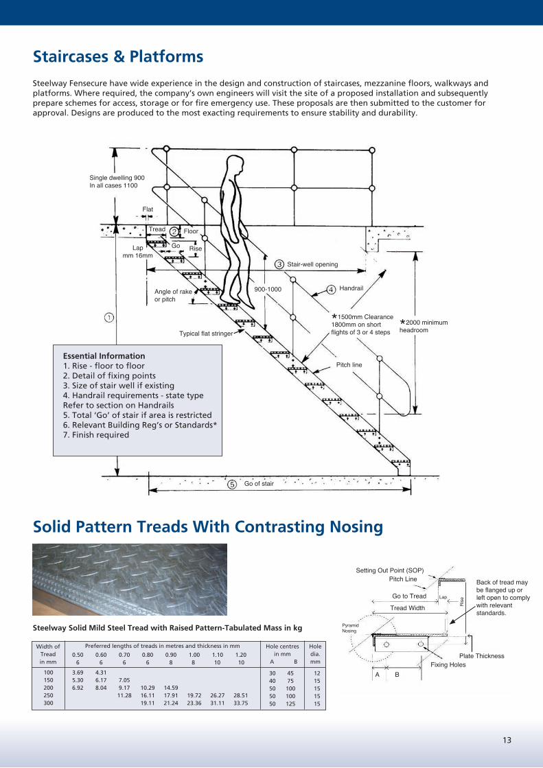
Staircases & Platforms
Steelway Fensecure have wide experience in the design and construction of staircases, mezzanine floors, walkways and platforms. Where required, the company’s own engineers will visit the site of a proposed installation and subsequently prepare schemes for access, storage or for fire emergency use. These proposals are then submitted to the customer for approval. Designs are produced to the most exacting requirements to ensure stability and durability.
Solid Pattern Treads With Contrasting Nosing
Steelway Solid Mild Steel Tread with Raised Pattern-Tabulated Mass in kg
Width ofTreadin mm
Preferred lengths of treads in metres and thickness in mm Hole centresin mm
A B
Hole dia.mm
100150200250300
3.69 4.31 5.30 6.17 7.05 6.92 8.04 9.17 10.29 14.59 11.28 16.11 17.91 19.72 26.27 28.51 19.11 21.24 23.36 31.11 33.75
30 45 12 40 75 15 50 100 15 50 100 15 50 125 15
0.50 0.60 0.70 0.80 0.90 1.00 1.10 1.20 6 6 6 6 8 8 10 10
Essential Information1. Rise - floor to floor2. Detail of fixing points3. Size of stair well if existing4. Handrail requirements - state typeRefer to section on Handrails5. Total ‘Go’ of stair if area is restricted6. Relevant Building Reg’s or Standards*7. Finish required
Single dwelling 900In all cases 1100
Flat
Tread Floor
Lapmm 16mm
Angle of rake or pitch
RiseGo
Typical flat stringer
Stair-well opening
900-1000 Handrail
Pitch line
*1500mm Clearance1800mm on shortflights of 3 or 4 steps *2000 minimum
headroom
Go of stair
Back of tread may be flanged up or left open to comply with relevant standards.
Setting Out Point (SOP)Pitch Line
Go to Tread
Tread Width
Fixing HolesA B
Plate Thickness
Ris
eLap
Pyramid Nosing

14
Open Mesh Stair Treads
Available in both Diamond and Rectangular Patterns, to complement the flooring range. Steelway open type treads embody all the advantages of open steel flooring i.e. lightweight, strong, durable, self draining, slip resistant contrasting nosing.
Available in a wide range of lengths & standard widths with slip resistant nosing.
Steelway open mesh treads are normally manufactured using the following flooring sections.Treads to 900mm long from 25 x 5mm section
1200mm long from 30 x 5mm section1425mm long from 35 x 5mm section1500mm long from 40 x 5mm section
End plates are 65 x 6mm flat and standard end plate drilling details are given in tables.
If required back of tread can be provided with a closed riser plate to comply with relevant standards.
Diamond Pattern Treads
85 15 35 12 M10
125 30 45 12 M10
165 30 75 15 M12
205 30 100 15 M12
245 30 125 15 M12
285 30 150 15 M12
325 30 175 15 M12
365 30 175 15 M12
Tread Widthin mm
40mm Centres A B Hole Dia. Bolt Dia.
Hole Centresin mm
Rectangular Pattern Treads
Tread Widthin mm
41/100 34/100 A B Hole Dia. Bolt Dia.
Hole Centresin mm
87 107 95 15 35 12 M10
128 141 125 30 45 12 M10
169 175 155 30 75 15 M12
185 30 100 15 M12
210 209 215 30 100 15 M12
251 243 245 30 125 15 M12
292 280 275 30 150 15 M12
313 305 30 175 15 M12
333 345 335 30 175 15 M12
30/100
NosingsNosings can be supplied suitable for fixing to new or existing concrete or timber steps. They are of extruded aluminium sections with either carborundum, rubber or fabric infilling.
Pan Type Treads
Back of tread may be flanged up or left open to comply with relevant standards.

15
Companionway Stair / Ship Type Ladder
Ship type /companion ladders, offer an alternative option in a situation where a vertical ladder is unsuitable and there is insufficient space for a staircase.
The 65 degree to 75 degree slope is easier to negotiate than a vertical or near vertical ladder. We recommend that the maximum vertical rise should not exceed 3000mm and the width between stringers should preferably be between limits of 450mm and 550mm.It should be noted that 250mm minimum foot space should be allowed from the nose of treads to the wall, platform face or other obstruction, see illustration. A top tread should be provided at floor level, or the platform can be arranged to run over, but the minimum foot space should still be maintained. Handrails are necessary on this type of ladder and should be provided on both sides without exception.
Chart giving useful recommendations for staircases
This chart gives preferred rise/go dimensions see section coloured yellow for any given rake of staircase or ladder. Rise and go on stairs to comply with relevant specification:
‘Go’ is the term used for the horizontal dimension of a stair or tread.
‘Rise’ is the vertical dimension.
‘Overlap’ is the amount the nosing of one tread overlaps the one below (minimum16mm).
Example: A single flight stair has a rise of 2600mm and has to comply with aminimum tread ‘go’ of 250mm and a maximum rise of 190mm. From the chart opposite we see with a ‘go’ of 250mm an acceptable rise will be about 185mm. This will give 14 equal rises. The stair will thus have an angle of rake pitch of 36º 36’ and will fall within the limits required for this type of stair. Also the aggregate of twice the rise plus the go equals 620mm, close to the optimum recommended in BS EN ISO 14122-3:2016.
Single line handrail must be fitted to each side of step ladders and be continuous with platform/gantry top handrail. Handrail should open out at the top to give a clear width of 610 mm and the opening should be protected by a self closing gate.
The surface of the top tread should be positioned at platform level and there should be the least possible gap between tread and platform.
Setting out for finding handrail height and clearance for headroom (step/ship type ladders only).
Stringers should not project more that 50mm beyond the nosing of the bottom tread.
Height to top handrail
1100mm
250 min.
100mm min. tread width.
Go of step ladder
65° - 75° rake
Tread Go
Tread rise 225-255mm
all rises should be
equal
20mm min. lap
16
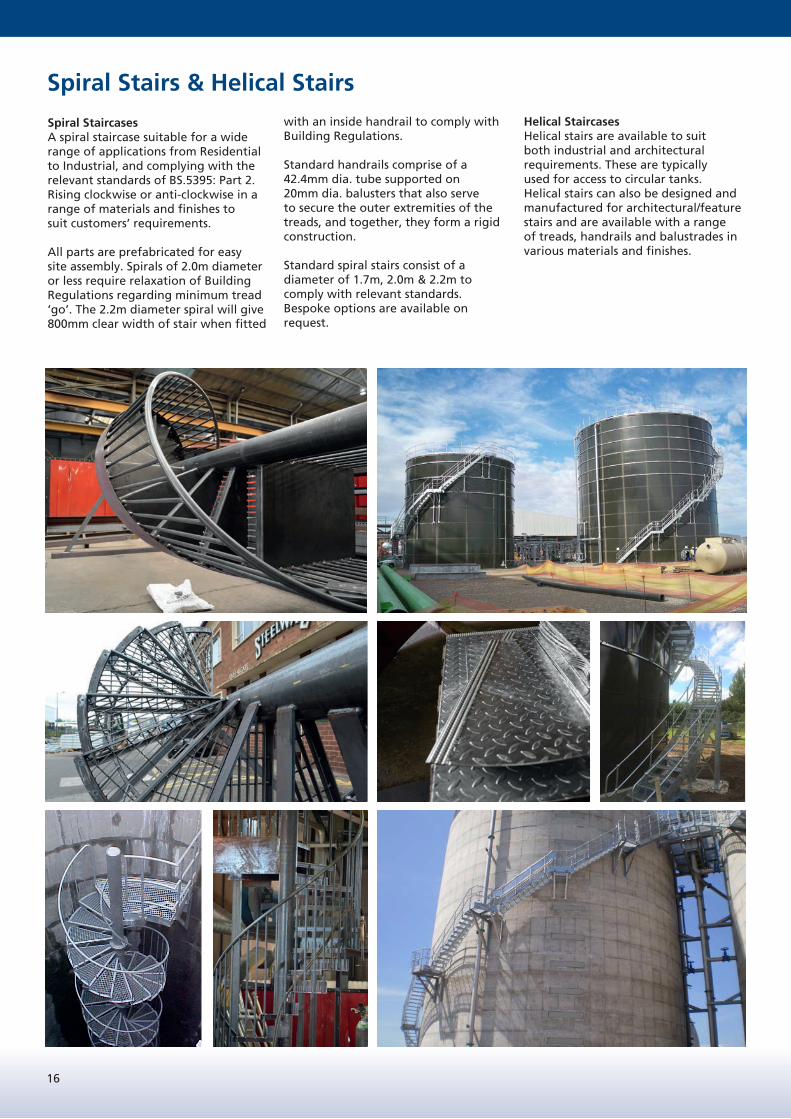
Spiral Stairs & Helical Stairs
Spiral StaircasesA spiral staircase suitable for a wide range of applications from Residential to Industrial, and complying with the relevant standards of BS.5395: Part 2. Rising clockwise or anti-clockwise in a range of materials and finishes tosuit customers’ requirements.
All parts are prefabricated for easy site assembly. Spirals of 2.0m diameter or less require relaxation of Building Regulations regarding minimum tread ‘go’. The 2.2m diameter spiral will give 800mm clear width of stair when fitted
with an inside handrail to comply with Building Regulations.
Standard handrails comprise of a 42.4mm dia. tube supported on 20mm dia. balusters that also serve to secure the outer extremities of the treads, and together, they form a rigid construction.
Standard spiral stairs consist of a diameter of 1.7m, 2.0m & 2.2m to comply with relevant standards. Bespoke options are available on request.
Helical StaircasesHelical stairs are available to suit both industrial and architectural requirements. These are typically used for access to circular tanks. Helical stairs can also be designed and manufactured for architectural/feature stairs and are available with a range of treads, handrails and balustrades in various materials and finishes.

17
Handrail & Guardrails
General ApplicationAs a general rule, any unprotected edge of a walkway, platform, staircase or other raised area from which a person may fall more than 0.5m must be fitted with a guardrail. Steelway handrails and guardrails are designed to provide safety and give reassurance for users of staircases and walkways. They may be of tubular or solid construction or a combination of both. We supply handrails not only to complement our staircases. platforms, and other similar structures, but also as completely independent items to fit customers own equipment or civil engineering work etc.
All component parts are tailor-made in easy to handle lengths and clearly marked for assembly on site. Drawings are provided for customers’ use where they wish to undertake the site erection themselves. Alternatively, we can provide a speedy and efficient site installation service.
DesignOur designs follow the recommendation of BS EN ISO 14122-1:2016, BS 5395-3, BS 4592-0 and BS 6180. There are at least two horizontal rails - a top rail (handrail) and an intermediate rail (knee rail) at approximately mid height. For step (companion) ladders and staircases in close proximity to, or bounded by a wall, a single handrail only is required with a minimum clearance for the hand of 50-75mm** (EEMUA publication 105 recommends a minimum of 100mm). If glazed areas occur adjacent to a walkway, platform, balcony or staircase, they should be guarded by a secure handrail or balustrade.
Wherever possible, handrails should be continuous and follow the exposed edge of raised platform areas and staircases. Sharp changes of direction in the vertical plane should be avoided in runs of handrail. The minimum height of handrails for platforms walkways and landings is 1.1m above the walking surface; for staircases the handrail height should be between 0.9m and 1m above the pitch line. Handrails should terminate in a swept end, either to the wall or to the knee rail, or return to the standards.
Note: Sharp corners, protrusions and stop ends should be avoided since these may catch clothing and cause accidents. Return bends (‘U’ bends) should not extend more than 350mm from the centre line of the standards. At the foot of staircases, ‘U’ bends should extend to the point of maximum extension of the stringer.
LoadingsBS 4592-0 recommends the following minimum design imposed lateral loads that should be used for handrails in industrial situations:General duty: 0.36 kN/mHeavy duty: 0.74 kN/mAreas subject to crowd loading ≥1.5m≤3.0m wide: 1.5 kN/mAreas subject to crowd loading ≥3m wide: 3.0 kN/m
If there is any possibility of vehicular impact, the recommendations in Annex A of BS 6180 should be followed.For light access stairs, gangways etc., which are not more than 600mm wide, a minimum design load of 0.22 kN/m may be used (BS EN 1991-1-1).
Protective TreatmentsSteel can be supplied in the following finishes:i) Self colour.ii) Prime paintiii) Hot dipped galvanised to BSENISO 1461. Recommended for exposed or corrosive conditions. Decorative paint finishescan be applied by the customer on top of galvanised materials, but a suitable priming system must be used prior to painting.iv) Nylon/Plastic coated. Not recommended for exposed conditions.v) Powder coated finishes are available to special order.
Aluminium alloy and stainless steel do not normally require protective treatment. However. where additional protection or improved appearance is thought necessary, then aluminium can be anodised and stainless steel polished.
Note: Some discolouration may occur on Aluminium bends and heat affected areas when anodised.
HandrailsTubular and Solid mild steel handrails are available in a range of sizes
Tubular: 33.7 o/d x 3.2mm wall minimum, 42.4 o/d x 3.2mm wall minimum, 48.3 o/d x 4.0mm wall minimum,
Stainless steel handrails are available with ball type standards, but all welded construction can also be accommodated.
Aluminium tubular handrail is also available on request in a range of sizes.
** BS 5395
Solid: 25mm dia. solid bar 32mm dia. solid bar

18
Spacing Between StandardsSWL tables A and B take into account thelimiting stress for the grade of steelspecified. A partial safety factor of ϒQ = 1.5has been allowed for. The horizontal displacement of any part of the barrier should not exceed 25mm. Allowance hasbeen made for the combined deflection ofhandrails and standards. Note: the actual spacing of handrail standards may be dependent upon the type base plate, connections and support / substructure.
Typical arrangement of Handrails for Stairs, Platforms and Walkways
900 1100 1250
Specification of handrail standards Specification of rail42.4x 3mm CHS x 80mm dia. Ball 33.7x 3mm CHS 1800 1750 140042.4x 3mm CHS x 80mm dia. Ball 42.4x 3mm CHS 1800 1800 150048.3x 4mm CHS x 80mm dia. Ball 42.4x 3mm CHS 1800 1800 180048.3x 4mm CHS x 80mm dia. Ball 48.3x 4mm CHS 1800 1800 180060.3x 4mm CHS x 80mm dia. Ball 48.3x 4mm CHS 1800 1800 1800
32mm Dia. x 70mm dia. Ball 33.7x 3mm CHS 1800 1450 110038mm Dia. x 70mm dia. Ball 42.4x 3mm CHS 1800 1800 1800
900 1100 1250
Specification of handrail standards Specification of rail42.4x 3mm CHS x 80mm dia. Ball 33.7x 3mm CHS 1250 1050 N/A42.4x 3mm CHS x 80mm dia. Ball 42.4x 3mm CHS 1250 1050 N/A48.3x 4mm CHS x 80mm dia. Ball 42.4x 3mm CHS 1800 1650 130048.3x 4mm CHS x 80mm dia. Ball 48.3x 4mm CHS 1800 1750 135060.3x 4mm CHS x 80mm dia. Ball 48.3x 4mm CHS 1800 1800 1800
32mm Dia. x 70mm dia. Ball 33.7x 3mm CHS 1250 N/A38mm Dia. x 70mm dia. Ball 42.4x 3mm CHS 1800 1400 1000
Material grade S275 JOH
Solid
Tubular
Solid
Tubular
Material grade S275 JOH
Maximum Spacing at design load
Max'm spacing (mm) Mild steel handrail standards where intensity of horizontal loading = 0.36 kN/mHeight of handrail standards (mm)
Maximum Spacing at design load
Max'm spacing (mm) Mild steel handrail standards where intensity of horizontal loading = 0.74 kN/mHeight of handrail standards (mm)
Overall length of Handrail between Bends
Maximum spacing of Standards 1800 Note: X to be 300 max.
X + Y to be 1000 max.
Not more than 1000
Lower (Knee) rail
Stringer (Pitch Line)
Min. 900Max. 1000
Balls of Standards fitted with grub screws to prevent movement of Handrail
Optimum height 1100min Maxium spacing of Handrail
Standard 1800
Top HandrailNote: Where Return Bends (U Bends) are fitted at the end of a length of Handrail they should not extend more than 350mm beyond the Handrail Standard
Not more than 300
Handrails joined to suit relevant standards
Toe (kick) plate min. height 100mm

19
Handrail Standards
Steelway tubular and solid ball type standards are made in varying heights to suit single, double and multi-line handrails. Balls are drilled to suit handrails or can be fitted with eyes for chains. Grub screws are a standard fitment in balls to secure handrails against movement.
Note: Handrail standards must not be supported from toe plates, unless it can be shown that the toe plates arestructural members.
Tubular and Solid ball type mild steel standards are available in a variety of types and sizes. A handrail system may be tubular or solid, or a combination of both e.g. tubular handrails with solid standards. However, it is important to select a standard with adequate ball size to be compatible with the diameter of handrail to be used, as illustrated on page 18.
Details regarding the spacing between Standards at different Loadings are given on page 18.
Aluminium tubular Standards are also available to complement the Aluminium tubular handrailing.
We have a range of base plate options to suit your individual requirements. A larger size of base is more suitable when fixing to materials which have a lower density than steel e.g. concrete, brickwork, block work. The size and spacing of fixing bolts into concrete or other low density materials requires careful consideration. There is an optimum requirement for fixings, and exceeding this may weaken rather than strengthen the attachment.
When ordering please indicate whether solid type or tubular type standards are required, and state:
1) Height.2) Ball centres.3) Diameter of ball/shank.4) Outside diameter of handrail.
Hei
gh
t to
Sta
nd
ard
Hei
gh
t to
Sta
nd
ard
Balls and bases welded to Shank
Max. 350 Min. 5xNB + 75 for
Horizontal Rails
NOTE:It is necessary to increase the minimum dimension for raking handrails depending on pitch
Walking Standards (Datum)
Hei
gh
t to
Han
dra
il
Single
4
Double DoubleTriple

20
Gates Where loading access is required for a mezzanine floor, or for protection across openings at the head of stairs and ladders. we can supply gates of tubular construction to match the design of adjoining handrails.
Infill Panels and Mesh GuardsWhere a two line system of handrail is preferred or for existing handrails where the need arises for additional protection, we can provide infill panels. These panels can be offered in various patterns the standard being 50mm sq welded mesh constructed from 3.25mm dia. wire with heavy gauge wire frame surrounds and supplied complete with fixing clips for securing to handrails/standards.
As an alternative to wire mesh infill panels we can offer perforated or solid infill panels.
Handrail continued
Self closing hinged tubular gate should be fitted in preference to safety chains.

21
GRP Products
The benefits of GRP materials are numerous
• Low weight• Corrosion resistance• Low maintenance• Low conductivity to heat and
electricity• Non magnetic• Non sparking
GRP Products Available:• Staircases• Platforms/Walkways• Handrails• Ladders• Bespoke Structures
GRP ‘Safegrip’ PlankingSupplied in standard ISO polyester panels 6m*0.5m. Panels can be cut and shaped to size as required. Gritted top walking surface.
‘Safegrip’
Complete support structures are available constructed from GRP sections with stainless steel fixings, in both fire and non fire retardant GRP materials.
Open Mesh Floor Panels in GRP have been designed to fulfill industry’s need for a versatile, corrosion resistant system that can be used either internally or externally.
GRP Industrial Flooring is suitable for numerous applications, and although designed primarily as a walking surface, it can be adapted for use as trench covers, grilles and drainage gratings. It is ideal for installation in special problem areas such as chemical, metal finishing and processing plants, it being resistant to chemical, electrolytic and atmospheric erosion.
Standard panels are made of glass reinforced polyester resin which offers resistance at an economical cost, however, the degree of corrosion and chemical resistance is dependent on the type of resin used. GRP has excellent electrical and thermal insulation properties.
GRP Moulded GratingsAvailable in 25mm, 38mm or 50mm thick in standard ISO polyester panels 1.22m*3.66m. Gritted top walking surface.
*standard colours available: Grey; Green;Yellow subject to availability


E X P E R T S I N S T E E L
E X P E R T S I N S T E E L
Steelway is a leading engineering and fabrication company that specialises in the manufacture and installation of steel, aluminium and GRP products.
Our dedicated workforce prides itself on its professionalism and quality fi nish. We are experts in our fi eld.
Queensgate Works, Bilston Road, Wolverhampton, West Midlands WV2 2NJ
Tel: 01902 451733 Fax: 01902 452256 Email: [email protected]
www.steelway.co.uk
STEELWAY
Other brochures available from the Steelway Group.
For more information, please visit our website www.steelway.co.uk
Steelway Group Brochure
Steelway Brickhouse Brochure
Steelway General Fencing
Brochure
Steelway Rail Brochure