Thank You FCC -- Now We Have 1.2 Ghz of 6 GHz Spectrum so ...
26
© 2020 SCTE•ISBE and NCTA. All rights reserved. 1 Thank You FCC -- Now We Have 1.2 Ghz of 6 GHz Spectrum so How Does the Cable Operator Utilize It? A Technical Paper prepared for SCTE•ISBE by J.R. Flesch Director, Advanced Technology, HN/CPE Commscope 3871 Lakefield Drive [email protected] Bryan Pavlich Staff SW Engineer Commscope 3871 Lakefield Drive 678 473 8346 [email protected] Kurt Lumbatis Distinguished SW Engineer Commscope 3871 Lakefield Drive 678 473 2921 [email protected] Charles Cheevers CTO/CPE and HN Commscope 3871 Lakefield Drive 678 473 8507 [email protected]
Transcript of Thank You FCC -- Now We Have 1.2 Ghz of 6 GHz Spectrum so ...

© 2020 SCTE•ISBE and NCTA. All rights reserved. 1
Thank You FCC -- Now We Have 1.2 Ghz of 6 GHz Spectrum so
How Does the Cable Operator Utilize It?
A Technical Paper prepared for SCTE•ISBE by
J.R. Flesch Director, Advanced Technology, HN/CPE
Commscope 3871 Lakefield Drive
Bryan Pavlich Staff SW Engineer
Commscope 3871 Lakefield Drive
678 473 8346 [email protected]
Kurt Lumbatis
Distinguished SW Engineer Commscope
3871 Lakefield Drive 678 473 2921
Charles Cheevers CTO/CPE and HN
Commscope 3871 Lakefield Drive
678 473 8507 [email protected]
© 2020 SCTE•ISBE and NCTA. All rights reserved. 2
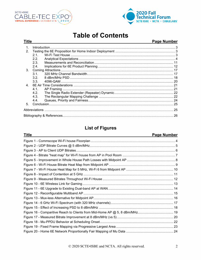
Table of Contents Title Page Number
1. Introduction .......................................................................................................................................... 3 2. Testing the 6E Proposition for Home Indoor Deployment .................................................................. 3
2.1. Wi-Fi Test House ................................................................................................................... 3 2.2. Analytical Expectations .......................................................................................................... 4 2.3. Measurements and Reconciliation ....................................................................................... 11 2.4. Implications for 6E Product Planning ................................................................................... 12
3. Coming Attractions ............................................................................................................................ 17 3.1. 320 MHz Channel Bandwidth............................................................................................... 17 3.2. 8 dBm/MHz PSD .................................................................................................................. 18 3.3. 4096-QAM ............................................................................................................................ 20
4. 6E Air Time Considerations .............................................................................................................. 21 4.1. AP Framing .......................................................................................................................... 21 4.2. The Single Radio Extender (Repeater) Dynamic ................................................................. 22 4.3. The Rectangular Mapping Challenge .................................................................................. 22 4.4. Queues, Priority and Fairness .............................................................................................. 24
5. Conclusion ......................................................................................................................................... 25
Abbreviations .............................................................................................................................................. 25 Bibliography & References.......................................................................................................................... 26
List of Figures
Title Page Number Figure 1 - Commscope Wi-Fi house Floorplan ............................................................................................. 4 Figure 2 - UDP Bitrate Curves @ 5 dBm/MHz .............................................................................................. 5 Figure 3 - AP to Client UDP Bitrates ............................................................................................................. 6 Figure 4 - Bitrate “heat map” for Wi-Fi house from AP in Pool Room .......................................................... 7 Figure 5 - Improvement in Whole House Path Losses with Midpoint AP ..................................................... 8 Figure 6 - Wi-Fi House Bitrate Heat Map from Midpoint AP ......................................................................... 9 Figure 7 - Wi-Fi House Heat Map for 5 MHz, Wi-Fi 6 from Midpoint AP .................................................... 10 Figure 8 - Impact of Contention at 5 GHz ................................................................................................... 11 Figure 9 - Measured Bitrates Throughout Wi-Fi House .............................................................................. 12 Figure 10 - 6E Wireless Link for Gaming .................................................................................................... 13 Figure 11 - 6E Upgrade to Existing Dual-band AP at WAN ........................................................................ 14 Figure 12 - Reconfigurable Multiband AP ................................................................................................... 15 Figure 13 - Mux-less Alternative for Midpoint AP........................................................................................ 16 Figure 14 - 6 GHz Wi-Fi Spectrum (with 320 MHz channels) ..................................................................... 17 Figure 15 - Effect of Increasing PSD to 8 dBm/MHz .................................................................................. 18 Figure 16 - Comparitive Reach to Clients from Mid-Home AP @ 5, 8 dBm/MHz ....................................... 19 Figure 17 - Measured Bitrate Improvement at 8 dBm/MHz (vs 5) .............................................................. 20 Figure 18 - Mu-PPDU Behavior at Scheduling Onset ................................................................................. 22 Figure 19 - Fixed Frame Mapping via Progressive Largest Area ............................................................... 23 Figure 20 - Home 6E Network Proportionally Fair Mapping of Mu Data .................................................... 24
© 2020 SCTE•ISBE and NCTA. All rights reserved. 3
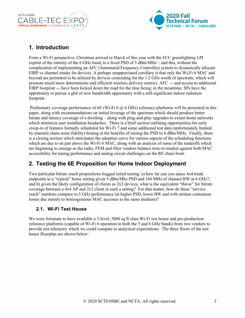
1. Introduction From a Wi-Fi perspective, Christmas arrived in March of this year with the FCC greenlighting LPI exploit of the entirety of the 6 GHz band, to a fixed PSD of 5 dBm/MHz – and this, without the complication of implementing an AFC (Automated Frequency Controller) system to dynamically allocate EIRP vs channel masks for devices. A perhaps unappreciated corollary is that only the Wi-Fi 6 MAC and beyond are permitted to be utilized by devices contending for the 1.2 GHz worth of spectrum, which will promote much more deterministic and efficient wireless delivery metrics. AFC -- and access to additional EIRP footprint --, have been kicked down the road for the time being; in the meantime, SPs have the opportunity to pursue a glut of new bandwidth opportunity with a still-significant indoor radiation footprint.
Preliminary coverage performance of 6E (Wi-Fi 6 @ 6 GHz) reference platforms will be presented in this paper, along with recommendations on initial leverage of the spectrum which should produce better bitrate and latency coverage of a dwelling – along with plug-and-play upgrades to extant home networks which minimize user installation headaches. There is a brief section outlining opportunities for early creep-in of features formally scheduled for Wi-Fi 7 and some additional test data (unfortunately limited by transmit chain noise fidelity) hinting at the benefits of raising the PSD to 8 dBm/MHz. Finally, there is a closing section which anticipates the adoption curve for various aspects of the scheduling functions which are due to sit just above the Wi-Fi 6 MAC, along with an analysis of some of the tradeoffs which are beginning to emerge as the radio, FEM and filter vendors balance time-to-market against both MAC accessibility for tuning performance and analog circuit challenges on the RF chain front.
2. Testing the 6E Proposition for Home Indoor Deployment Two particular bitrate reach propositions begged initial testing: a) how far can you space 4x4 trunk endpoints in a “typical” home setting given 5 dBm/Mhz PSD and 160 MHz of channel BW at 6 GHz?; and b) given the likely configuration of clients as 2x2 devices, what is the equivalent “throw” for bitrate coverage between a 4x4 AP and 2x2 client in such a setting? For that matter, how do these “service reach” numbers compare to 5 GHz performance (at higher PSD, lower BW and with airtime contention losses due mainly to heterogeneous MAC accesses to the same medium)?
2.1. Wi-Fi Test House
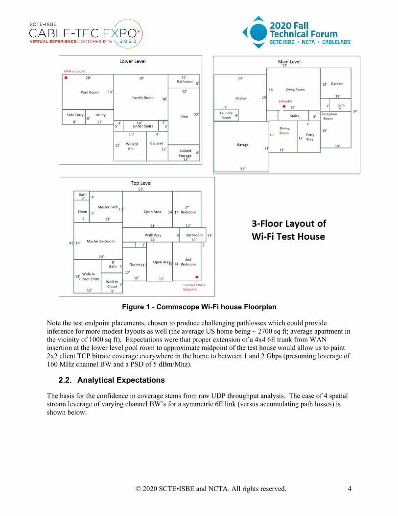
We were fortunate to have available a 3-level, 5000 sq ft class Wi-Fi test house and pre-production reference platforms (capable of Wi-Fi 6 operation in both the 5 and 6 GHz bands) from two vendors to provide test telemetry which we could compare to analytical expectations. The three floors of the test house floorplan are shown below:
© 2020 SCTE•ISBE and NCTA. All rights reserved. 4
Figure 1 - Commscope Wi-Fi house Floorplan
Note the test endpoint placements, chosen to produce challenging pathlosses which could provide inference for more modest layouts as well (the average US home being ~ 2700 sq ft; average apartment in the vicinity of 1000 sq ft). Expectations were that proper extension of a 4x4 6E trunk from WAN insertion at the lower level pool room to approximate midpoint of the test house would allow us to paint 2x2 client TCP bitrate coverage everywhere in the home to between 1 and 2 Gbps (presuming leverage of 160 MHz channel BW and a PSD of 5 dBm/Mhz).
2.2. Analytical Expectations
The basis for the confidence in coverage stems from raw UDP throughput analysis. The case of 4 spatial stream leverage of varying channel BW’s for a symmetric 6E link (versus accumulating path losses) is shown below:

© 2020 SCTE•ISBE and NCTA. All rights reserved. 5
Figure 2 - UDP Bitrate Curves @ 5 dBm/MHz
Note that the abscissa lays out losses past 1 meter off of the antennae. It is also noteworthy that the general shape of the MCS breaks (bitrate steps) is exactly mirrored across all BW – this is due to EIRP being metered exactly as a function of occupied BW (fixed PSD). In terms of actual link performance, these UDP asymptotes will be reduced by TCP overheads (typically 10-20%, depending on packet parameters) and will also be subject to implementation losses (systemic, as analog RF chain fidelity issues – principally noise and filter shape; and circumstantial, as spatial stream compromises – polarization and element diversity losses).
With respect to asymmetrical 6E link performance, a similar UDP bitrate waterfall can be estimated for the case of a 4x4 AP linking with a 2x2 client:
© 2020 SCTE•ISBE and NCTA. All rights reserved. 6
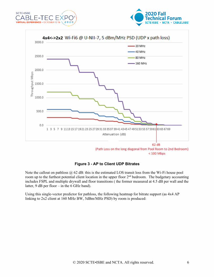
Figure 3 - AP to Client UDP Bitrates
Note the callout on pathloss @ 62 dB: this is the estimated LOS transit loss from the Wi-Fi house pool room up to the furthest potential client location in the upper floor 2nd bedroom. The budgetary accounting includes FSPL and multiple drywall and floor transitions ( the former measured at 4.5 dB per wall and the latter, 9 dB per floor – in the 6 GHz band).
Using this single-vector predictor for pathloss, the following heatmap for bitrate support (as 4x4 AP linking to 2x2 client at 160 MHz BW, 5dBm/MHz PSD) by room is produced:
© 2020 SCTE•ISBE and NCTA. All rights reserved. 7
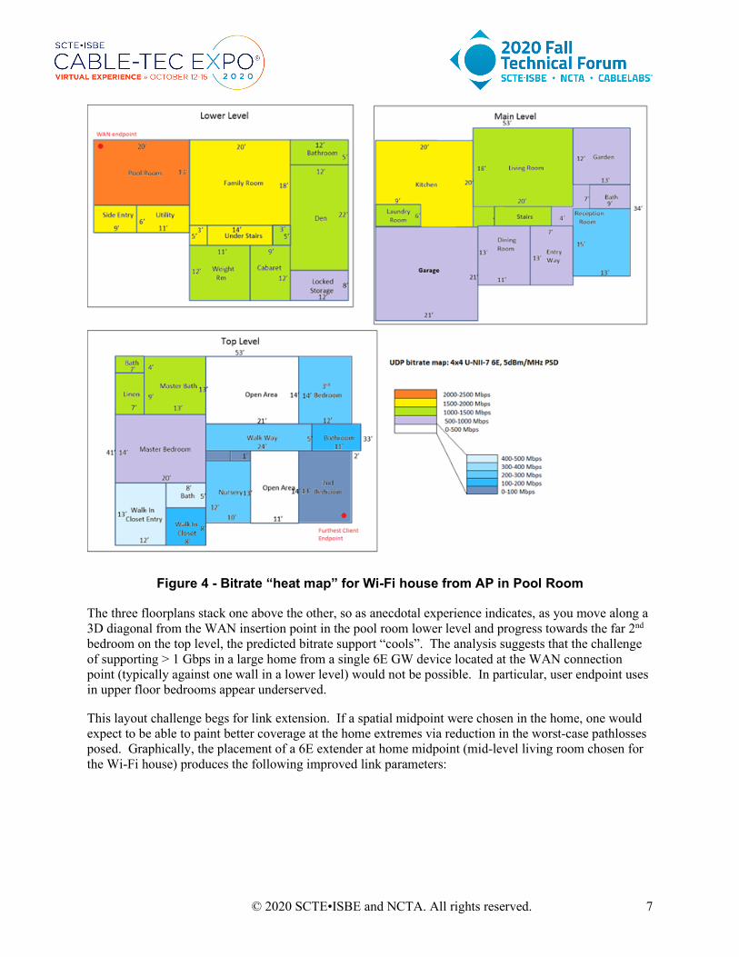
Figure 4 - Bitrate “heat map” for Wi-Fi house from AP in Pool Room
The three floorplans stack one above the other, so as anecdotal experience indicates, as you move along a 3D diagonal from the WAN insertion point in the pool room lower level and progress towards the far 2nd bedroom on the top level, the predicted bitrate support “cools”. The analysis suggests that the challenge of supporting > 1 Gbps in a large home from a single 6E GW device located at the WAN connection point (typically against one wall in a lower level) would not be possible. In particular, user endpoint uses in upper floor bedrooms appear underserved.
This layout challenge begs for link extension. If a spatial midpoint were chosen in the home, one would expect to be able to paint better coverage at the home extremes via reduction in the worst-case pathlosses posed. Graphically, the placement of a 6E extender at home midpoint (mid-level living room chosen for the Wi-Fi house) produces the following improved link parameters:
© 2020 SCTE•ISBE and NCTA. All rights reserved. 8
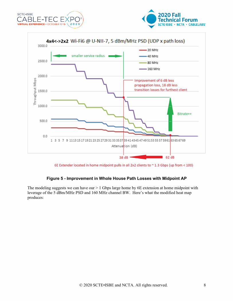
Figure 5 - Improvement in Whole House Path Losses with Midpoint AP
The modeling suggests we can have our > 1 Gbps large home by 6E extension at home midpoint with leverage of the 5 dBm/MHz PSD and 160 MHz channel BW. Here’s what the modified heat map produces:

© 2020 SCTE•ISBE and NCTA. All rights reserved. 9
Figure 6 - Wi-Fi House Bitrate Heat Map from Midpoint AP
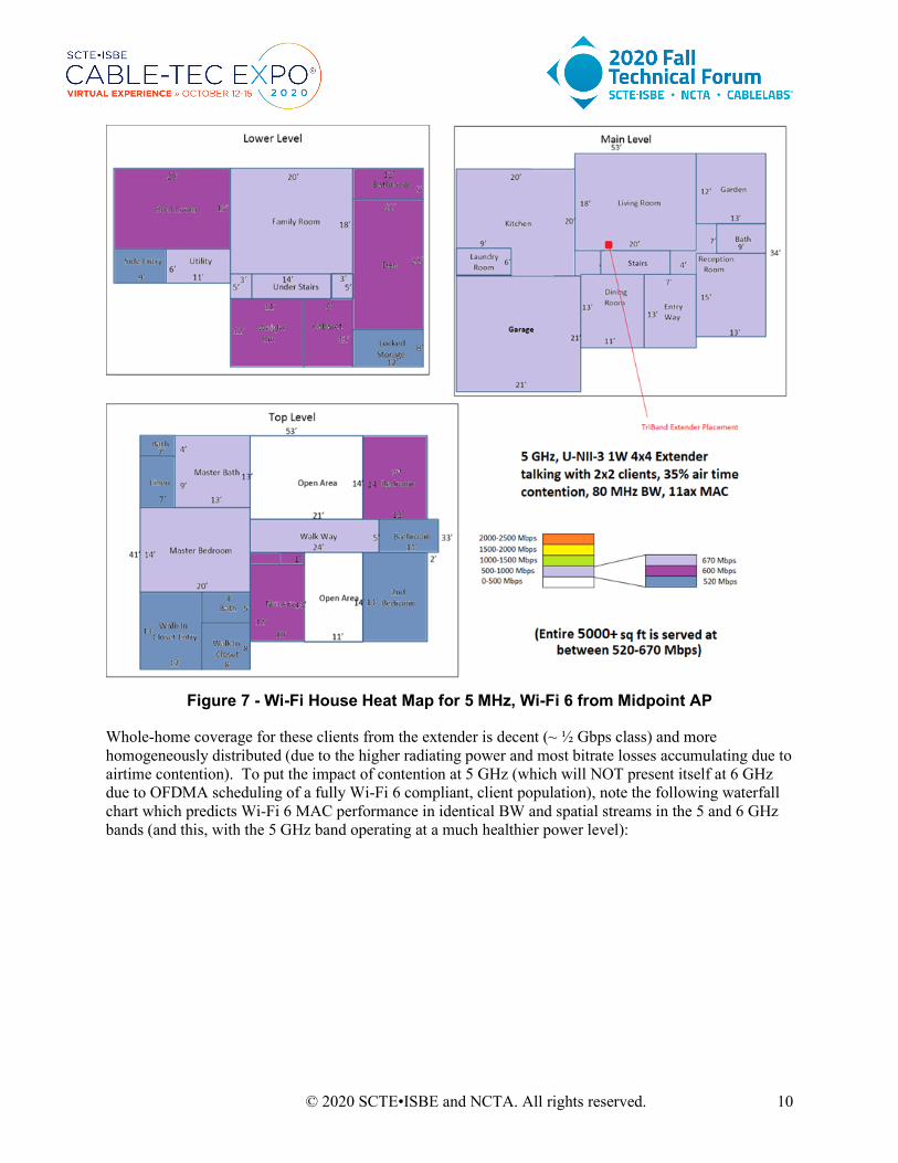
If the extender is multiband (a sensible enough proposition, given the foregone conclusion of legacy clients) then we can also predict coverage at 5 GHz, using a Wi-Fi 6 MAC on a 4x4 AP capable of 1W EIRP at 80 MHz BW (but restricted to 65% airtime access due to contention):
© 2020 SCTE•ISBE and NCTA. All rights reserved. 10
Figure 7 - Wi-Fi House Heat Map for 5 MHz, Wi-Fi 6 from Midpoint AP
Whole-home coverage for these clients from the extender is decent (~ ½ Gbps class) and more homogeneously distributed (due to the higher radiating power and most bitrate losses accumulating due to airtime contention). To put the impact of contention at 5 GHz (which will NOT present itself at 6 GHz due to OFDMA scheduling of a fully Wi-Fi 6 compliant, client population), note the following waterfall chart which predicts Wi-Fi 6 MAC performance in identical BW and spatial streams in the 5 and 6 GHz bands (and this, with the 5 GHz band operating at a much healthier power level):

© 2020 SCTE•ISBE and NCTA. All rights reserved. 11
Figure 8 - Impact of Contention at 5 GHz
These results beg some questions on extender band profile, spatial stream assignment and RF chain management (including antennae multiplexing, perhaps) for proper future-proofing of client band and MAC migration; we will tend to that in a later section.
2.3. Measurements and Reconciliation
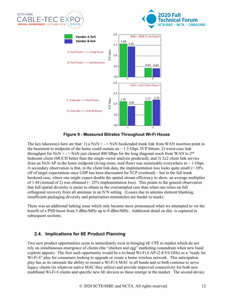
Multiple days of testing were conducted at the Wi-Fi house to vet performances of the alternate vendor candidates and tune device alignments for repeatable data-taking in the various 6E use cases. The summary results for these follows:
© 2020 SCTE•ISBE and NCTA. All rights reserved. 12
Figure 9 - Measured Bitrates Throughout Wi-Fi House
The key takeaways here are that: 1) a NxN < - > NxN bookended trunk link from WAN insertion point in the basement to midpoint of the home could sustain an ~ 1.5 Gbps TCP bitrate; 2) worst-case link throughput for NxN < - > NxN just cleared 400 Mbps for the long diagonal reach from WAN to 2nd bedroom client (MUCH better than the single-vector analysis predicted); and 3) 2x2 client link service from an NxN AP in the home midpoint (living room, mid-floor) was sustainable everywhere to ~ 1 Gbps. A secondary observation is that, in the client link data, the implementation loss looks quite small (< 10% off of target expectations once UDP has been discounted for TCP overhead) – but in the full trunk bookend case, where one might expect double the spatial stream efficiency to show, an average multiplier of 1.44 (instead of 2) was obtained (~ 25% implementation loss). This points to the general observation that full spatial diversity is easier to obtain in the oversampled case than when one relies on full orthogonal recovery from all antennae in an N:N setting. (Losses due to antenna element blanking, insufficient packaging diversity and polarization mismatches are harder to mask).
There was an additional lurking issue which only became more pronounced when we attempted to vet the benefit of a PSD boost from 5 dBm/MHz up to 8 dBm/MHz. Additional detail on this is captured in subsequent sections.
2.4. Implications for 6E Product Planning
Two new product opportunities seem to immediately exist in bringing 6E CPE to market which do not rely on simultaneous emergence of clients (the “chicken and egg” marketing conundrum when new band exploits appear). The first such opportunity would be a tri-band Wi-Fi 6 AP (2.4/5/6 GHz) as a “ready for Wi-Fi 6” play for consumers looking to upgrade or create a home wireless network. This anticipation play has as its rationale the ability to mount a Wi-Fi 6 MAC in all bands and so both continue to serve legacy clients (in whatever native MAC they utilize) and provide improved connectivity for both new multiband Wi-Fi 6 clients and specific new 6E devices as these emerge in the market. The second device
© 2020 SCTE•ISBE and NCTA. All rights reserved. 13
would appear to be a bridging device (Ethernet to 6E) which could be applied against several “touchless” home wireless network upgrades. Some use case examples follow.
A key marketing opportunity lies in the superior latency and contention-free performance of 6E. Not mentioned in prior sections but potentially holding the key for particular service mounts at 6 GHz is the notion that, until the rather prodigious link capacities of 160 MHz channel operation in the band are reached (and scheduling onset occurs in the AP), link latency easily outperforms that encountered in either of the 5 GHz bands or 2.4 GHz (as in: a sub-millisec asymptote – essentially the time required to rasterize the arriving data against all available RU’s and dispatch it). Viewed this way, 6 GHz may be thought of as virtual wireline (which need not be pulled, obviously).
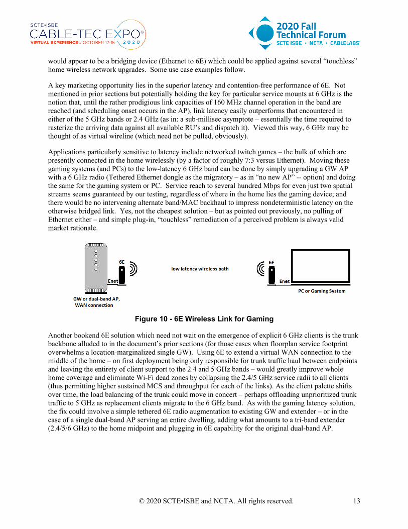
Applications particularly sensitive to latency include networked twitch games – the bulk of which are presently connected in the home wirelessly (by a factor of roughly 7:3 versus Ethernet). Moving these gaming systems (and PCs) to the low-latency 6 GHz band can be done by simply upgrading a GW AP with a 6 GHz radio (Tethered Ethernet dongle as the migratory – as in “no new AP” -- option) and doing the same for the gaming system or PC. Service reach to several hundred Mbps for even just two spatial streams seems guaranteed by our testing, regardless of where in the home lies the gaming device; and there would be no intervening alternate band/MAC backhaul to impress nondeterministic latency on the otherwise bridged link. Yes, not the cheapest solution – but as pointed out previously, no pulling of Ethernet either – and simple plug-in, “touchless” remediation of a perceived problem is always valid market rationale.
Figure 10 - 6E Wireless Link for Gaming
Another bookend 6E solution which need not wait on the emergence of explicit 6 GHz clients is the trunk backbone alluded to in the document’s prior sections (for those cases when floorplan service footprint overwhelms a location-marginalized single GW). Using 6E to extend a virtual WAN connection to the middle of the home – on first deployment being only responsible for trunk traffic haul between endpoints and leaving the entirety of client support to the 2.4 and 5 GHz bands – would greatly improve whole home coverage and eliminate Wi-Fi dead zones by collapsing the 2.4/5 GHz service radii to all clients (thus permitting higher sustained MCS and throughput for each of the links). As the client palette shifts over time, the load balancing of the trunk could move in concert – perhaps offloading unprioritized trunk traffic to 5 GHz as replacement clients migrate to the 6 GHz band. As with the gaming latency solution, the fix could involve a simple tethered 6E radio augmentation to existing GW and extender – or in the case of a single dual-band AP serving an entire dwelling, adding what amounts to a tri-band extender (2.4/5/6 GHz) to the home midpoint and plugging in 6E capability for the original dual-band AP.

© 2020 SCTE•ISBE and NCTA. All rights reserved. 14
Figure 11 - 6E Upgrade to Existing Dual-band AP at WAN
This segues into the notion of adaptable AP resource allocation – specifically with respect to analog circuit elements and antenna farm exploits. The multiplexing options lay out nicely if one allows for broadband-matched antennae and potentially, FEMs. Different price points will determine base multiband capability, but a specific example might drive home the point. Presuming that 2.4/5 GHz FEMs can be stretched to both 2.4/5 and 2.4/6 GHz devices (the built-in diplexers bifurcating the 2.4 from the other, common, band support), we already have the BAW/SAW devices which delineate the 2.4, 5 and 6 GHz bands (so-called “coexistence filters”) and so can consider our switching options. Hypothesizing an adaptable 8-chain AP leads to this, among other, possible implementations:

© 2020 SCTE•ISBE and NCTA. All rights reserved. 15
Figure 12 - Reconfigurable Multiband AP
This diagram describes the potential of multiband FEMs and configurable 5/6 GHz radio chips to implement an AP with reconfigurable band coverage – as might be advantageous when addressing the desire to first upgrade MAC capability in the lower bands before switching on actual 6E support for new client devices (as they come available). And while not evident in radio vendor planning at this stage, it is not inconceivable that configurable Wi-Fi 6 radios for 2.4/5/6 GHz appear some day (along with supporting infrastructure like wideband FEMs and triplexers). Clearly, every home’s traffic profiles will be at least slightly different, so to the extent that band and spatial stream flexibility can be designed in, such adaptability improves market edge.
A quick sidebar is in order. As a more philosophical discussion, the exploit of the 2.4 GHz ISM band for Wi-Fi might be ripe for reconsideration given the advent of the many, unfortunately disparate, IoT radio mesh exploits which target that same spectrum (Zigbee, Thread, BLE). Coordinated exploit of the band by the many interested parties is a bit brute force and clumsy at this stage and perhaps a graceful exit (or at minimum, an explicit band-sharing FDM solution) may be the future play for 802.11. The flip side of the coin may also show forth: IoT applications normally relegated to other radio technologies may find new homes in Wi-Fi 6 narrowband assignment. To the extent that constrained end devices could host a Wi-Fi 6 stack, this bears watching.
© 2020 SCTE•ISBE and NCTA. All rights reserved. 16
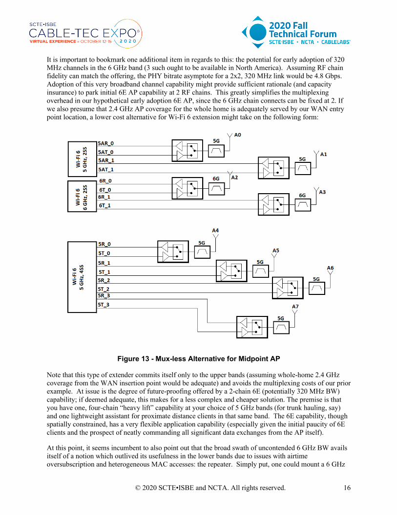
It is important to bookmark one additional item in regards to this: the potential for early adoption of 320 MHz channels in the 6 GHz band (3 such ought to be available in North America). Assuming RF chain fidelity can match the offering, the PHY bitrate asymptote for a 2x2, 320 MHz link would be 4.8 Gbps. Adoption of this very broadband channel capability might provide sufficient rationale (and capacity insurance) to park initial 6E AP capability at 2 RF chains. This greatly simplifies the multiplexing overhead in our hypothetical early adoption 6E AP, since the 6 GHz chain connects can be fixed at 2. If we also presume that 2.4 GHz AP coverage for the whole home is adequately served by our WAN entry point location, a lower cost alternative for Wi-Fi 6 extension might take on the following form:
Figure 13 - Mux-less Alternative for Midpoint AP
Note that this type of extender commits itself only to the upper bands (assuming whole-home 2.4 GHz coverage from the WAN insertion point would be adequate) and avoids the multiplexing costs of our prior example. At issue is the degree of future-proofing offered by a 2-chain 6E (potentially 320 MHz BW) capability; if deemed adequate, this makes for a less complex and cheaper solution. The premise is that you have one, four-chain “heavy lift” capability at your choice of 5 GHz bands (for trunk hauling, say) and one lightweight assistant for proximate distance clients in that same band. The 6E capability, though spatially constrained, has a very flexible application capability (especially given the initial paucity of 6E clients and the prospect of neatly commanding all significant data exchanges from the AP itself).
At this point, it seems incumbent to also point out that the broad swath of uncontended 6 GHz BW avails itself of a notion which outlived its usefulness in the lower bands due to issues with airtime oversubscription and heterogeneous MAC accesses: the repeater. Simply put, one could mount a 6 GHz
© 2020 SCTE•ISBE and NCTA. All rights reserved. 17
repeater as an AP mid-home and orchestrate air time on that single 6E radio for what would function as front- and backhaul between otherwise farflung and bitrate-lean clients. Such an arrangement could be implemented in straightforward fashion with an AC-plugged “wall wart” and might represent the means by which either distant clusters of 6E clients – or a bit-hungry single 6E service mount in a detached shed or garage – gets its high bitrate and low latency connection to the home edge WAN located an appreciable distance away. Prior instantiations of the repeater function required explicit diplexing of the repeat trunk, essentially replicating air time losses on an additional channel. While merely inconvenient and problematic in the 5 GHz band, such implementation at the grossly oversubscribed 2.4 GHz band meant such attempts were all but doomed. 6E’s expansive spectrum would allow many of these private “repeat” meshes to co-exist without extracting a penalty on the “main” channel.
3. Coming Attractions The ink on the March FCC announcement laying out the access to a new chunk of spectrum for Wi-Fi has not even dried and there are already three areas of bitrate service growth which are garnering attention. Two of these are related to scaling features planned for Wi-Fi 7 (320 MHz channel BW and 4096-QAM) – and the other has to do with unlicensed spectrum proponents wishing to migrate to a slightly higher PSD (8 dBm/MHz vs the present 5). All of these should yield opportunities for link improvement but there is also a clear benefit hierarchy to the proportional improvements one might expect. These are covered in decreasing magnitude of impact in the following sections.
3.1. 320 MHz Channel Bandwidth
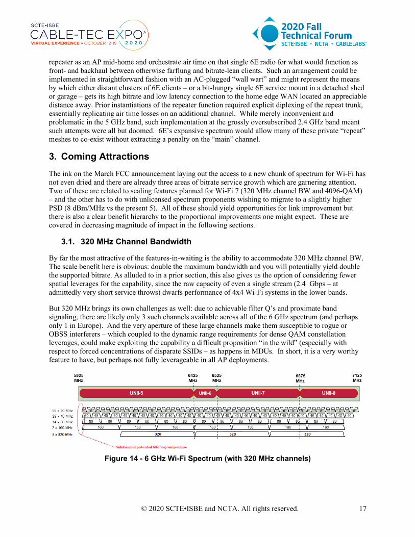
By far the most attractive of the features-in-waiting is the ability to accommodate 320 MHz channel BW. The scale benefit here is obvious: double the maximum bandwidth and you will potentially yield double the supported bitrate. As alluded to in a prior section, this also gives us the option of considering fewer spatial leverages for the capability, since the raw capacity of even a single stream (2.4 Gbps – at admittedly very short service throws) dwarfs performance of 4x4 Wi-Fi systems in the lower bands.
But 320 MHz brings its own challenges as well: due to achievable filter Q’s and proximate band signaling, there are likely only 3 such channels available across all of the 6 GHz spectrum (and perhaps only 1 in Europe). And the very aperture of these large channels make them susceptible to rogue or OBSS interferers – which coupled to the dynamic range requirements for dense QAM constellation leverages, could make exploiting the capability a difficult proposition “in the wild” (especially with respect to forced concentrations of disparate SSIDs – as happens in MDUs. In short, it is a very worthy feature to have, but perhaps not fully leverageable in all AP deployments.
Figure 14 - 6 GHz Wi-Fi Spectrum (with 320 MHz channels)
© 2020 SCTE•ISBE and NCTA. All rights reserved. 18
3.2. 8 dBm/MHz PSD
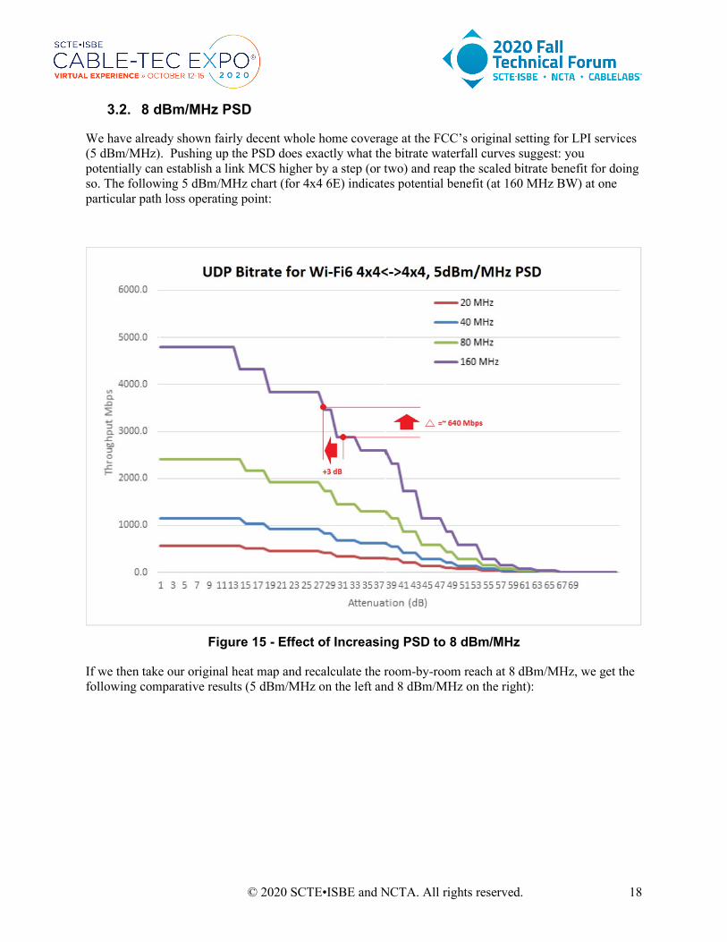
We have already shown fairly decent whole home coverage at the FCC’s original setting for LPI services (5 dBm/MHz). Pushing up the PSD does exactly what the bitrate waterfall curves suggest: you potentially can establish a link MCS higher by a step (or two) and reap the scaled bitrate benefit for doing so. The following 5 dBm/MHz chart (for 4x4 6E) indicates potential benefit (at 160 MHz BW) at one particular path loss operating point:
Figure 15 - Effect of Increasing PSD to 8 dBm/MHz
If we then take our original heat map and recalculate the room-by-room reach at 8 dBm/MHz, we get the following comparative results (5 dBm/MHz on the left and 8 dBm/MHz on the right):
© 2020 SCTE•ISBE and NCTA. All rights reserved. 19
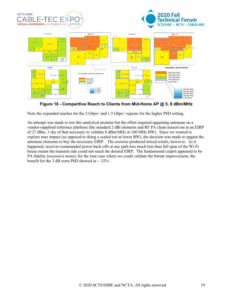
Figure 16 - Comparitive Reach to Clients from Mid-Home AP @ 5, 8 dBm/MHz
Note the expanded reaches for the 2 Gbps+ and 1.5 Gbps+ regions for the higher PSD setting.
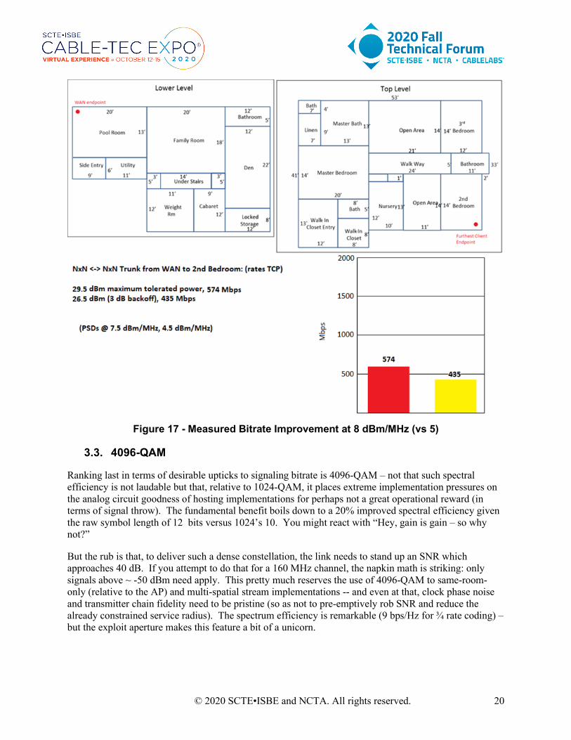
An attempt was made to test this analytical promise but the effort required upgaining antennae on a vendor-suppliied reference platform (the standard 2 dBi elements and RF PA chain maxed out at an EIRP of 27 dBm, 3 shy of that necessary to validate 8 dBm/MHz at 160 MHz BW). Since we wanted to explore max impact (as opposed to doing a scaled test at lower BW), the decision was made to upgain the antennae elements to buy the necessary EIRP. The exercise produced mixed results, however. As it happened, receiver-commanded power back-offs at any path loss much less than full span of the Wi-Fi house meant the transmit side could not reach the desired EIRP. The fundamental culprit appeared to be PA fidelity (excessive noise); for the lone case where we could validate the bitrate improvement, the benefit for the 3 dB extra PSD showed as ~ 32%:
© 2020 SCTE•ISBE and NCTA. All rights reserved. 20
Figure 17 - Measured Bitrate Improvement at 8 dBm/MHz (vs 5)
3.3. 4096-QAM
Ranking last in terms of desirable upticks to signaling bitrate is 4096-QAM – not that such spectral efficiency is not laudable but that, relative to 1024-QAM, it places extreme implementation pressures on the analog circuit goodness of hosting implementations for perhaps not a great operational reward (in terms of signal throw). The fundamental benefit boils down to a 20% improved spectral efficiency given the raw symbol length of 12 bits versus 1024’s 10. You might react with “Hey, gain is gain – so why not?”
But the rub is that, to deliver such a dense constellation, the link needs to stand up an SNR which approaches 40 dB. If you attempt to do that for a 160 MHz channel, the napkin math is striking: only signals above ~ -50 dBm need apply. This pretty much reserves the use of 4096-QAM to same-room-only (relative to the AP) and multi-spatial stream implementations -- and even at that, clock phase noise and transmitter chain fidelity need to be pristine (so as not to pre-emptively rob SNR and reduce the already constrained service radius). The spectrum efficiency is remarkable (9 bps/Hz for ¾ rate coding) – but the exploit aperture makes this feature a bit of a unicorn.

© 2020 SCTE•ISBE and NCTA. All rights reserved. 21
4. 6E Air Time Considerations The Wi-Fi 6 MAC contains five particularly noteworthy framing aspects (Trigger Frames, Block Acks, Buffer Status polling, TWT and MU-OFDMA) which streamline wireless community accesses to the medium. Applied to a wide channel BW, these AP-managed on-air exchanges can mimic data arrival heuristics to an impressive bitrate threshold before queueing techniques (as for differential service data priorities) need be invoked and introduce something other than simple dispatch latencies to the delivery time for the packets involved. Air time access in general will move between variable-width data exchange windows (scaled via the amount of data to be moved in order to empty buffers) and framed exchanges whose duration defines a maximum performance latency target for prioritized traffic. In all cases, there is algorithmic art performed which seeks to exploit the rectangular capacity posed by RU’s x frame time. And all this need be exhausted before resort of a second AP radio (channel) to overlay an FDM option to the proceedings should be considered to alleviate single channel exhaustion.
The general scheduling opportunity in Wi-Fi 6 decomposes along two fronts: the scheme for mapping RU’s in the OFDMA matrix to fit the AP’s client demands and the fairness doctrine applied to whatever queueing scheme is adopted to stage data for dispatch.
4.1. AP Framing
A high-altitude summary of the framing structure for 6E communications – which is commanded exclusively by the AP, is in order. Essentially, Trigger Frames are used by the AP to coordinate single user, multi-user and upstream PDUs on the channel in question. The ability to coordinate multi-user exchanges via OFDMA mapping is also critical to the higher efficiencies in Wi-Fi 6, since simultaneous access to the channel can be synchronized across all clients. (Mu-MIMO offers another exploitable axis – spatial diversity -- but though this is specified, Wi-Fi MAC implementations to date have eschewed this as overwrought).
In addition to the data transfers, status details and general housekeeping can be coordinated through triggered responses for the multi-user environment as well. Simple Block Acks to close out TCP requirements fall into this category. In addition, by soliciting Buffer Status Reports from clients, the AP has access to a key metric for determining scheduled queue servicing priorities based upon its knowledge of its own queues, all the client queues and target scavenging bitrates represented by the applied MCS @ RU profile assigned to each particular client. With this knowledge, any of the proportionately fair (PF) scheduling algorithms (M-LWDF or EXP-PF -- common to LTE and WiMAX OFDMA networks) may be employed to serve clients should brute-force FIFO rasterization of the outbound (or inbound) data start to produce framed exchanges that approach the maximum targeted frame size for the given channel bandwidth (scheduler onset). A reasonable bound for this might be something on the order of 5 msec or so.

© 2020 SCTE•ISBE and NCTA. All rights reserved. 22
Figure 18 - Mu-PPDU Behavior at Scheduling Onset
4.2. The Single Radio Extender (Repeater) Dynamic
In one of our analytical cases, we describe the deployment of an extender AP to provide a mid-home anchor point to virtually extend the home WAN attachment to a more convenient radiating point for balanced support of 6E clients. This scenario does introduce an air time complexity for the trunk link, summarized by the realization that the single channel capacity calculation necessarily involves both the 4x4 hauling trunk and multiple 2x2 client links. Both of these capacities impinge on the single channel air time, with clients attached to the extender essentially consuming two blocks of air time (to/from the midpoint, with repeated to/from the WAN endpoint for backhaul/fronthaul) and with clients associated with the WAN side only accounting for single transfers each. The air time hit is not necessarily double for the extender clients, however, since the trunk capacity is defined by 4 spatial streams @ the MCS for the trunk and the client impact is essentially 2 spatial streams at a different extender/client link MCS (might be higher or lower than the trunk MCS and depends on client distance from the extender). The key is that the higher the sustained MCS to the clients can be made, the less demand on airtime to service them; and the overriding goal is air time efficiency (clients / frame).
4.3. The Rectangular Mapping Challenge
Because LTE and WiMAX have already tilted these windmills, there is a glut of prior art describing different schemes for assigning RU’s to client service needs in very demanding capacity scenarios (typical client counts going into the hundreds). (Refer to the reference section.) Such is not likely to materialize for 6E home networks for the forseeable future and there is value in simplifying some of the more elaborate schemes from those mobile networks to suit the more limited scale of home meshes (to cost benefit, or marginalization of firmware complexity). To put it more bluntly, SU data packaging – even if concatenated for several (few) users, looks to be the dominant initial scheduling tactic for 6E’s emergence. This involves simply rasterizing the outbound data over full exploit of the channel BW available (as RU’s) until buffer exhaustion – and repeating the behavior for other clients when such data intermittently arrives. Multiple simultaneous browser sessions describe this type of scenario.
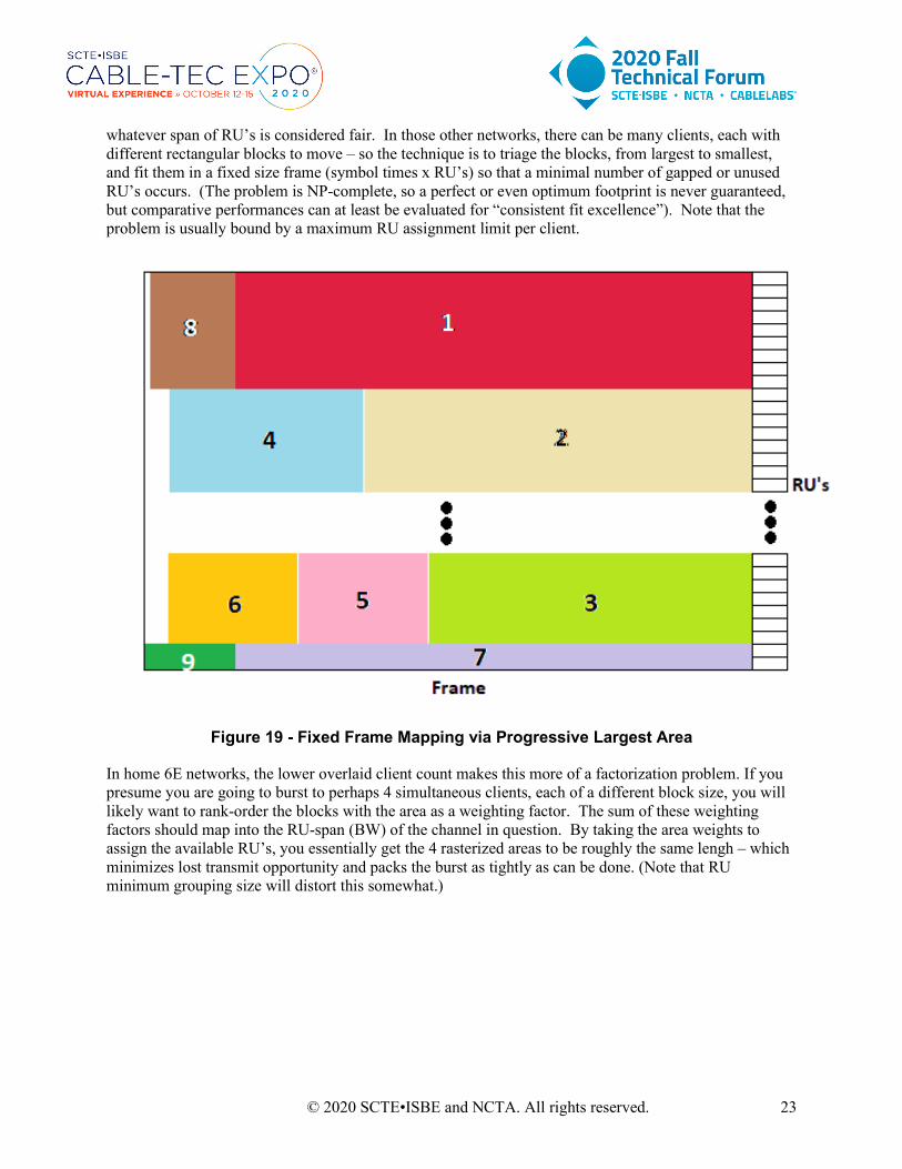
However, once streaming applications get mounted (especially in tandem), MU data dispatch dominates and actual stepped rectangular fitment begins to be necessary. In broad strokes, data bound for dispatch to multiple clients can be represented as a strip of symbols – such symbols he result of the achievable MCS on its own link. This strip, taken as a rectangle of area 1, can be applied in raster fashion across
© 2020 SCTE•ISBE and NCTA. All rights reserved. 23
whatever span of RU’s is considered fair. In those other networks, there can be many clients, each with different rectangular blocks to move – so the technique is to triage the blocks, from largest to smallest, and fit them in a fixed size frame (symbol times x RU’s) so that a minimal number of gapped or unused RU’s occurs. (The problem is NP-complete, so a perfect or even optimum footprint is never guaranteed, but comparative performances can at least be evaluated for “consistent fit excellence”). Note that the problem is usually bound by a maximum RU assignment limit per client.
Figure 19 - Fixed Frame Mapping via Progressive Largest Area
In home 6E networks, the lower overlaid client count makes this more of a factorization problem. If you presume you are going to burst to perhaps 4 simultaneous clients, each of a different block size, you will likely want to rank-order the blocks with the area as a weighting factor. The sum of these weighting factors should map into the RU-span (BW) of the channel in question. By taking the area weights to assign the available RU’s, you essentially get the 4 rasterized areas to be roughly the same lengh – which minimizes lost transmit opportunity and packs the burst as tightly as can be done. (Note that RU minimum grouping size will distort this somewhat.)

© 2020 SCTE•ISBE and NCTA. All rights reserved. 24
Figure 20 - Home 6E Network Proportionally Fair Mapping of Mu Data
4.4. Queues, Priority and Fairness
It is becoming painfully evident that radio vendors will be reserving details of the rectangular mapping algorithm – along with frame sizing – for themselves to implement, leaving little tuning capability for users aside from QoS designation. The number of QoS levels will define the number of queues allowed (plus at least one shunt lane for pre-emptive priority – TWT -- or retransmissions). In LTE space, a typical algorithmic first resort is a move to two queues: “real-time” and “non-real-time” to be able to express a priority for traffic where latency and jitter are less tolerated (typically media streams). This simple bifurcation usually sees a reservation for somewhere between half and three-quarters of the link capacity for real-time consideration, with the balance (and the unused reserved) available for non-real-time traffic. This is likely to find its way into 6E networks – and stacks on top of the rectangular filling exercise above in the following way: instead of just one queue sourcing the blocks of data to be transferred, there are two or more (all but the last with a reserved area). The fitment problem is simply stepwise executed on successive priorities. First, all the top priority blocks get mapped against that reserved area, from largest area to smallest. If space is left over after priority traffic exhaustion, this is reclaimed for priority 2 (plus its own reserve). Priority 2 is mapped in similar fashion and whatever residual is left is used to accommodate the last priority. This exercise is truncated if the maximum framing area is reached before buffer exhaustion. In all cases, buffers are appropriately FIFO-shuffled (and the next frame is queued).

© 2020 SCTE•ISBE and NCTA. All rights reserved. 25
5. Conclusion Wi-Fi’s gifted new spectrum – with a MAC ante which sheds 20 years of multi-epoch, stacked and somewhat organic growth, is a shot of adrenaline for wireless indoor networks. The healthy LPI EIRP footprint of 5 dBm/MHz (without the complexity of seeking AFC database permissions and perhaps with more level yet to come) looks to provide Gbps+ coverage and low-millisec signaling latency to even large floorplan American homes. Additional coverage insurance may come by way of additional channel BW in the not-too-distant future. With the Covid-19 pressures to WAN infrastructure apparently driving a new technology tranche there, the opportunity to craft even more demanding wireless home applications stand to be vastly improved. Certainly, media-infused experiences which immerse the user will be easier to mount – and with a much more robust signaling conduit to support IoT devices, expectations for next-generation remote applications – particularly security, telemedicine and aging-in- place, go up as well.
Eventually, there will be enough client demand that scheduled air time at 6 GHz will become a necessity – but this eventuality may still be several years away, given the multiple Gbps of capacity represented by diverse spatial exploit of the channel BWs involved. In the interim, lessons from OFDMA scheduling of LTE and WiMAX systems (802.16e) – which have been around for over 10 years -- may find themselves represented in 6E networks. The deferred onset of need for efficient scheduling algorithms means relatively boilerplate commutating exercises (weighted round robin) with perhaps only a single premium queueing structure (two total queues) might provide all the fair access consideration required for early generation 6E home network scheduling agents.
Abbreviations
AC alternating current AFC automated frequency controller AP access point BAW bulk acoustic wave BLE Bluetooth Low Energy bps bits per second BW bandwidth EIRP effective isotropic radiated power EXP-PF exponential proportionately fair FDM frequency division multiplexing FEM front end module FCC Federal Communications Commission FIFO first in, first out FSPL free space path loss Gbps gigabit per second GHz gigahertz GW gateway ISM industrial, scientific and medical LOS line of sight LPI low power indoor LTE long term evolution

© 2020 SCTE•ISBE and NCTA. All rights reserved. 26
MAC media access control Mbps megabit per second MCS modulation and coding scheme MDU multiple dwelling unit MHz megahertz M-LWDF maximum-longest weighted delay first Msec milliseconds MU-MIMO Multiple-user, multiple in, multiple out MU-OFDMA multiple-user OFDMA OFDMA orthogonal frequency division multiple access PA power amplifier PSD power spectral density QAM quadrature amplitude modulation RF radio frequency RU resource unit SAW surface acoustic wave SCTE Society of Cable Telecommunications Engineers SPs service providers SSID service set identifier SU single user TCP transmission control protocol TWT targeted wait time UDP user datagram protocol W watt WAN wide area network WiMAX worldwide interoperability and microwave access 6E Wi-Fi 6 @ 6 GHz
Bibliography & References eOCSA: An Algorithm for Burst Mapping with Strict QoS Requirements in IEEE 802.16e Mobile WiMAX Networks; Chakchai So-In, Raj Jain and Abdel-Karim Al Tamimi, Dept of Computer Science and Engineering, Washington University in St. Louis
IEEE P802.11ax/D4.2: Draft Standard for Information technology – Telecommunications and information exchange between systems Local and metropolitan area networks – Specific requirements Part 11: Wireless LAN Medium Access Control (MAC) and Physical Layer (PHY) Specifications Amendment 1: Enhancements for High Efficiency WLAN; 802.11 Working Group of the LAN/MAN Standards Committee of the IEEE Computer Society, Copyright 2019
A Novel Algorithm for Efficient Downlink Packet Scheduling for Multiple-Component-Carrier Cellular Systems; Yao-Liang Chung, Department of Communications, Navigation and Control Engineering, National Taiwan Ocean University, November 2016
OFDMA Downlink Burst Allocation Mechanism for IEEE 802.16e Networks; Juan I. del-Castillo, Francisco M. Delicado and Jose M. Villal’on, Instituto de Investigaci’ on en Inform’atica de Albacete, UCLM, Spain