th Israeli Symposium on Jet Engines · This year, as in the previous 15 years, we plan to hold the...
36
יום העיון ה שישה עשר במנועי סילון וטורבינות גז16 th Israeli Symposium on Jet Engines and Gas Turbines November 9 2017, Department of Aerospace Engineering, Technion, Haifa, Israel BOOK OF ABSTRACTS יום ה,' כ' חשון ה' תשע" ח, 9/11/2017 אודיטוריו ם, בניין הפקולטה להנדסת אוירונוטיקה וחלל, טכניון, חיפה. המעבדה למנועי סילון וטורבינות גז הפקולטה להנדסת אוירונוטיקה וחלל הטכניו ן, חיפהhttp://jet-engine-lab.technion.ac.il ענף הנעה המחלקה לאויר ונוטיקה היחידה למו"פ- היחידה לתשתיות מנהלת פיתוח אמל"ח ותשתיות משרד הביטחון ענף הנעה מחלקת מטוסים להק ציוד חיל האויר
Transcript of th Israeli Symposium on Jet Engines · This year, as in the previous 15 years, we plan to hold the...

עשר שישהה העיון יום
גז וטורבינות סילון במנועי
16th Israeli Symposium on Jet Engines
and Gas Turbines November 9 2017
Department of Aerospace Engineering
Technion Haifa Israel
BOOK OF ABSTRACTS
9112017 חתשעה חשון כ ה יום
טכניון הפקולטה להנדסת אוירונוטיקה וחלל בניין םאודיטוריו
חיפה
המעבדה למנועי סילון וטורבינות גז הפקולטה להנדסת אוירונוטיקה וחלל
ן חיפההטכניו httpjet-engine-labtechnionacil
ענף הנעהונוטיקההמחלקה לאויר
היחידה לתשתיות-היחידה למופ מנהלת פיתוח אמלח ותשתיות
משרד הביטחון
ענף הנעה מחלקת מטוסים
להק ציוד חיל האויר
2
עשר שישהה העיון יום
גז וטורבינות סילון במנועי
16th Israeli Symposium on Jet Engines
and Gas Turbines November 9 2017
Department of Aerospace Engineering
Technion Haifa Israel
BOOK OF ABSTRACTS
9112017 חתשעה חשון כ ה יום
טכניון הפקולטה להנדסת אוירונוטיקה וחלל בניין אודיטוריום
חיפה
המעבדה למנועי סילון וטורבינות גז הפקולטה להנדסת אוירונוטיקה וחלל
ן חיפההטכניו httpjet-engine-labtechnionacil
ענף הנעהלאוירונוטיקההמחלקה
היחידה לתשתיות-היחידה למופ מנהלת פיתוח אמלח ותשתיות
משרד הביטחון
ענף הנעה מחלקת מטוסים
להק ציוד חיל האויר
3
Turbo and Jet Engine Laboratory Department of Aerospace Engineering Technion Haifa
httpjet-engine-labtechnionacil
THE 16th
ISRAELI SYMPOSIUM ON JET ENGINES AND GAS TURBINES
Venue Auditorium (room 235) Faculty of Aerospace Engineering Technion
Thursday November 9 2017 Technion Haifa
This year as in the previous 15 years we plan to hold the Israeli Symposium on Jet Engines and Gas
Turbines During the last few years there has seen a steady expansion of activities in Isreal in turbo jet
propulsion This is in addition to the serial production of small engines increased electricity generation
using gas turbines and combined cycles production of various engines spare parts and maintenance
work In Israel many bodies are active in jet engines and gas turbine area including MAFAT (MoD)
IAF Israel Navy EL-AL IAI Beit Shemesh Engines RAFAEL TAAS ORMAT Israel Electric
Corporation R-Jet amp Becker Engineering the Technion and more
Improved engineering amp technological innovations and new projects in Israel calls for continued
professional meetingsrsquo for the exchange of information for cross-pollination and for creating a fertile
seedbed for cooperation During the previous 15 symposia in every one more than hundred scientists
and propulsion engineers met and presented their work from the various industries the MoD and
Academia These symposia were a success wetting the appetite for more such meetings
The 16th symposium includes invited introductory lectures on selected subjects (from large engine
manufacturers and Academia) In addition there are presentations that concern activities in different
Israeli industrial firms institutes and upon request a tour to the facultys renovated Turbo and jet
Engine laboratory This is also be a good opportunity for professional meetings exchange of ideas and
presentation of jet engine models and products from various companies
During the symposium there will be an opportunity to discuss all topics relevant to jet engines and gas
turbines including innovative cycles aerodynamics of turbo-machines combustion heat transfer
structures and dynamics simulations control production processes and maintenance combined cycles
and more Preference will be given to subjects of interest in Israel
Typically the first half of the symposia (till lunch time) will be held in English
Please note that the presentation from the present 16th and the previous symposium (the15
th) symposium
can be seen in the following (Technionrsquos Jet Engine laboratoryrsquos) website
labtechnionacil-engine-httpsjet
All presentations will be published in full or as a censored version after the conference on the Jet
Engine Laboratory website (see below)
Looking forward for a fruitful and enjoyable symposium
Professor Yeshayahou Levy
Chairman of the symposium
Technion Faculty of Aerospace Engineering
e-mail levyytechnionacil httpjet-engine-labtechnionacil
Propulsion Branch
IMOD Propulsion Branch
IAF
4
16th
ISRAELI SYMPOSIUM ON JET ENGINES amp GAS TURBINES
TECHNICAL PROGRAM
16th ISRAELI SYMPOSIUM ON JET ENGINES amp GAS TURBINES NOVEMBER 9 2017
Auditorium Faculty of Aerospace Engineering (room 235)
(Registrationהרשמה ) 0900 - 0745
0900 Opening
Professor Yeshayahou Levy Chairman Faculty of Aerospace Engineering Technion
Professor Wayne D Kaplan
Executive Vice President for Research Technion ndash Israel Institute of Technology
Professor Yaakov Cohen
Dean Faculty of Aerospace Engineering Technion
Major Yigal Ben Shabat
Head Propulsion Systems Branch Aeronautical Division MODMFAT
Lieutenant Colonel Avi Yosfan
Head of Engineering Propulsion Branch IAF
(First Session In English) מושב ראשון 1310 - 0920
RECENT ADVANCEMENTS IN ENGINE DESIGN
35 min lectures
Session Chairman Yeshayahou Levy Technion
A1 ldquoIntegrated Thermal Management Systemsrdquo
Glenn Crabtree Consulting Engineer Military Systems Engineering GE Aviation
A2 ldquoThe Technical Evolution of Fighter Engine Propulsion in the IAFrdquo
Tom Prete Vice President Engineering Military Engines Pratt amp Whitney
A3 Thermal Mechanical Analysis of an Internally Cooled Stator
Bruno Aguilar Honeywell
(Break and refreshmentהפסקה וכיבוד קל ) 1125 - 1105
A4
ldquoEffects of manufacturing variability on unsteady interaction in a transonic turbinerdquo
John Clark Principal Engineer in Turbine Engine Division US Airforce
A5
ldquoIntegrated Approach for Direct Calculation of Off-Design Performance of Gas Turbine Enginerdquo
Abdul Nassar Managing Director Softinway
A6
ldquoA Radical View on the Improvement of Gas Turbine Technology and
Future Directionrdquo
Changmin Son Pusan National University S Korea
1310 -1430 מעבדה למנועי סילוןארוחת צהריים וסיור ב
(Lunch and laboratory visit)
5
16th
ISRAELI SYMPOSIUM ON JET ENGINES amp GAS TURBINES
Faculty of Aerospace Engineering Technion Haifa Israel
November 9 201 7
TECHNICAL PROGRAM (Cont) Lectures in Hebrew 20 min lectures
ד ובעברית 20כל ההרצאות 1430 - 1710
Second Sessionי נמושב ש
1430 -1530 room 165
Third Sessionמושב שלישי 1430 -1530 room 235
Design amp Optimization
Turbomachinery
Session Chairman
Savely Khosid Rafael Session Chairman
Beni Cukurel Technion
B1
ldquoOptimization in design of a miniature turbojet
engine Existing tools and potential of
implementationrdquo
Savely Khosid Ohad Miller
Manor Rafael LTd
C1
ldquoInfluence of Turbine Exit Flow Swirl on Exhaust Nozzle Performancerdquo
Ram Evron Zvi Gorali
BSE LTd
B2
ldquoEconomic Dispatch and Unit Commitment of a
Single Micro-Gas Turbine under CHP
Operationrdquo
Dan Zelazo Beni Cukurel
Technion
C2
ldquoIncreasing Efficiency of UAV Internal
Combustion Engines via Inverted Brayton
Cyclerdquo
Idan Chazan Beni Cukurel
Technion
B3
ldquoAero-Engine Fan Gearbox Designrdquo
Ilan Berlowitz
Israel Aerospace Industries
C3
ldquoMean-line optimum design of a small axial
turbine with millions configurationsrdquo
SKhosid M Goldbaum R Priampolsky
Manor Rafael LTd
1550-1530 (Break and refreshmentהפסקה וכיבוד קל )
Forth Session רביעימושב
1550 -1710 room 165
Fifth Sessionשי חמימושב
1550 -1710 room 235
Fuel amp Combustion
Systems amp Maintenance
D1
ldquoOn the Conversion of a Large Turbo Fan
Enginersquos Combustor To Be Fueled By Natural
Gasrdquo
Yeshayahou Levy
Technion
E1
ldquoOT or Not Issues concerning Over-
Temperature in Turbines Bladesrdquo
Capt Nitzan David Foucks
MampP Dept IAF
D2
ldquoOn the Development of a SMD Correlation for
a Spray Exiting from a Slinger Atomizer SMDrdquo
Ariel Cohen
BSE Ltd
E2
ldquoMonitoring Engine Gearbox as preventive
maintenancesrdquo
Yosi Pickel
IAF
D3
ldquoLean Premixed Prevaporized Combustion for Gas Turbines
Aharon David LPP Combustion LTd
E3
ldquoThe Danger of Water in Aircraft Fuel Systemsrdquo
Orian Elmaliach and Michal Yardeni
Fuel and Chemistry Department Materials Division
IAF
D4
Impact of fuel composition on the dynamics of
lean premixed combustion
Dan Michaels
Technion
E4
6
יום העיוןתודתנו נתונה לגופים ומוסדות אשר תמכו ב
AKNOWLEDGMENTS
7
A1
Integrated Thermal Management Systems
Glenn Crabtree
onsulting Engineer Military Systems Engineering GE AviationC
Current and emerging military aircraft have an exponentially increasing demand for power to
operate flight systems avionics and weapon systems This power demand creates significant
challenges for aircraft thermal management systems to reject this heat without compromise
to the aircraft mission systems or operational capability Simply expanding the capability of
current designs drives sub-optimal weight and volume of the power and thermal management
sub-system resulting in compromised aircraft operational capability To develop an optimal
aircraft platform a thermal management sub-system concept must be developed in parallel
with both the engine cycle and aircraft in the conceptual design phase Consequently system
level integration becomes a more critical constraint in the early stages of the design
process This presentation seeks to discuss these challenges and describes components sub-
system and system level approaches to improving future aircraft capability
8
A2
The Technical Evolution of Fighter Engine Propulsion in the IAF
Thomas W Prete
Vice President Engineering Military Engines
Pratt amp Whitney
The Israel Air Force has a long rich heritage of iconic fighter aircraft in their arsenal Over
these many years there have been many important technical advancement and innovations in
the design development and manufacturing of the propulsion systems for these aircraft that
continually improve the capability of these weapon systems and define their place in aviation
history
This talk explores and examines the evolution of these technical advancements and
innovations related to fighter aircraft jet engine propulsion systems over the last 40 years
beginning with engines like the J52 powering the A-4 to the present F135 which powers the F-
35I fighter It presents the design considerations of these systems in the context of jet engine
performance attributes such as thrust-to-weight fuel consumption safety amp reliability and
cost of ownership The talk then explores how product technologies and innovations design
and analytical capability and advancements in manufacturing and manufacturing modelling
have resulted in profound improvements in each propulsion system attribute Finally the talk
ends with a discussion about the future of propulsion system capability and what innovations
are being looked at to continue to improve their capability
This document has been publicly released copy 2017 United Technologies Corporation
9
A3
Thermal Mechanical Analysis of an Internally Cooled Stator
Bruno Aguilar
Honeywell
The demand for high performance and durable gas turbines continues to grow Next
generation high-efficiency turbine engines are increasing inlet temperatures to achieve higher
performance that consequently affects the durability of flow path components in the hot
section For instance the stator in Figure 1a experiences cyclical mechanical and thermal
loading leading to fatigue This phenomenon is known as Thermo-mechanical fatigue (TMF)
Therefore the prediction of accurate metal temperatures is becoming increasingly important
to predict cyclic thermal stresses and component life
In the past the prediction of metal temperature required multiple assumptions Industry in-
house code or the correlations in open literature and textbooks are typically used to generate
the internal andor external convective boundary conditions In many complicated cases
these convective boundary conditions relied on computational fluid dynamics (CFD)
especially when the full 3D CFD code matured and became a practical tool for gas turbine
thermal design However this CFD calculation required assigning wall temperature or heat
flux as the boundary condition where fidelity of the metal temperature highly depended on
the accuracy of the assumptions
In this study a conjugate heat transfer (CHT) analysis Figure 1b was implemented to calculate
steady state metal temperatures CHT has the ability to compute conduction of heat through
solids coupled with convective heat transfer from a fluid This new technique removes the
uncertainty associated with calculating metal-fluid boundary conditions Results from the CHT
were used to obtain boundary conditions to create a conduction thermal model to obtain
transient metal temperatures An engine transient thermal survey was completed to validate
the predictions from the thermal models Finally a 3D transient stress model was utilized to
identify locations of high stress locations and identify design changes to improve part
durability in the field
10
A4
The Effect of Manufacturing Variations on Unsteady Interaction in a Transonic
Turbine
Dr John Clark
Turbomachinery Branch Turbine Engine Division Aerospace Systems Directorate
Air Force Research Laboratory WPAFB OH
USA
The unsteady flowfield in a single-stage high work high pressure turbine that is paired with a
contra-rotating low pressure turbine is exceptionally complex and dominated by shock
interactions Recently a stage-and-one-half research turbine (See Fig 1) was developed at the
Air Force Research Laboratory (AFRL) in part as an effort to improve the accuracy of forced-
response predictions in such a situation Special attention was paid to the design of the blade to
ensure that the stage had as high efficiency and as low trailing-edge shock strength as possible
given the design point of the turbine Initial testing with the turbine indicated that the overall
physics of the shock interaction with a downstream vane was well predicted and this gave
credence to efforts to reduce the unsteadiness via 3D unsteady optimization However in
initial experiments there were still significant discrepancies between predicted levels of
unsteadiness on the blade suction side due to shock reflections from the downstream vane and
those measured in experiments Accordingly an effort is underway to determine the source of
such discrepancies and suggest improvements to the designeranalyst engaged in high-work
turbine development Specific studies are underway to improve the fidelity of grids to include
additional perhaps relevant physics such as conjugate heat transfer and fluid-structures
interaction to utilize more rigorous cooling and viscous flow modeling and to include as-
measured geometries in the analysis
This effort focuses on the comparison of unsteadiness due to as-measured turbine blades in the
transonic turbine to that obtained with blueprint geometries via Computational Fluid Dynamics
(CFD) A Reynolds-Averaged Navier-Stokes (RANS) flow solver with the two-equation Wilcox
turbulence model is used as the numerical analysis tool for comparison between the blueprint
geometries and as-manufactured geometries obtained from a structured light optical
measurement system The nominal turbine CFD grid data defined for analysis of the blueprint
blade was geometrically modified to reflect as-manufactured turbine blades using an
established mesh metamorphosis algorithm This approach avoids the tedious manual
regeneration of the CFD grid and does not rely on geometry obtained from Coordinate
Measurement Machine (CMM) sections but rather a point cloud representing the entirety of
the turbine blade Here surface pressure traces and the discrete Fourier transforms thereof
from numerical predictions of as-measured geometries are compared both to blueprint
predictions and to experimental measurements The importance of incorporating as-measured
geometries in analyses to explain deviations between numerical predictions of blueprint
geometries and experimental results is readily apparent Further analysis of every casting
produced in the creation of the test turbine yields variations that one can expect in both aero-
performance and unsteady loading as a consequence of manufacturing tolerances Finally the
11
use of measured airfoil geometries to reduce the unsteady load on a target blade (See Fig 2) in
a region of interest is successfully demonstrated
Fig 1 Unsteady interaction between a transonic turbine blade and a downstream vane that is consistent with a counter-rotating Low Pressure Turbine
Fig 2 Discrete Fourier Transform magnitudes (as a percentage of inlet total pressure)
on the blade surface due to shock reflections from the downstream vane On the left is
the prediction on a measured blade of interest On the right is a prediction of reduced
unsteadiness at sensor 7 due to replacement of selected blades
Shock
Boundary-
Layer
Interaction
Reflected Shocks
Shock
Wake
Interactions
1B
2V
12
A5
Integrated Approach for Direct Calculation of Off-design Performance of Gas
Turbine Engine
Nassar Abdul
Managing Director Softinway
Due to the versatility of the gas turbine to operate in both design and off-design conditions
they find their use in a number of applications as shaft power or propulsion power Many a
times they are forced to operate at conditions away from the design point thus making it
important to understand the performance at off-design operating modes and possibility
optimizing for even these modes if possible The complexity of predicting the off-design
performance increases when the gas turbine unit has cooling and secondary flows The
common approach to predict the off-design performance of the gas turbine unit is mapping
the compressor and turbine separately and the consequent matching of the common
operating points However this approach might be rather inaccurate when the cooling and
secondary flows are considered This affects not only on the efficiencies predicted but also on
the operating margin and blade burnouts
In this article a virtual test facility for predicting the off-design performance using a direct
calculation approach is presented Here the compressor and turbine performance is
calculated jointly in a single environment considering the cooling and secondary flow which
gives a more reliable prediction method for off-design operation without considering the
individual performance maps Figure 1 shows the general gas turbine layout with cooling
flows extracted from different stages of the compressor and the cooling flow injected into
different stages of the turbine for nozzle and blade cooling
Figure 1 General gas turbine layout with cooling flows
Typically the performance is calculated using maps of the compressor and turbine In the
virtual test facility the detailed calculation of the compressor and turbine is performed on a
real time basis using streamline calculation method More sophisticated calculation can be
performed by considering full 3D fluid flow analysis but it becomes computationally
13
expensive Here a simplified yet accurate method of calculation using the combination of
streamline solver for the flow path calculation of compressor and turbine and one-
dimensional flow and heat network for analyzing the cooling and secondary flows is used to
predict the off-design performance Figure 2 shows the virtual test facility flowchart for
performing direct calculation considering the cooling and secondary flows for a gas turbine
unit with power output of 166 MW Figure 3 shows the comparison of gas turbine efficiency
considering the direct calculation using virtual test facility and traditional approach using
component maps
Figure 2 Virtual test facility flowchart based on AxSTREAMreg platform tools powered by
AxSTREAM IONtrade
Figure 3 Gas turbine efficiency vs it power considering virtual test facility and maps
utilization approach
025
027
029
031
033
035
037
039
30 40 50 60 70 80 90 100
Un
it e
ffic
ien
cy
Power AxSTREAM Platform Tool for thermodynamic simulation
14
A6
A Radical View on the Improvement of Gas Turbine Technology and Future Direction
Prof Changmin Son
Pusan National University Busan Korea
changminsonpusanackr
The global trend of gas turbine development is to increase overall pressure ratio together
with turbine inlet temperature It is even more crucial to achieve small core development for
next generation turbofan engine ultrahigh bypass ratio gas turbine Such a trend is also valid
for UAV applications since smaller engine provides compact integration opportunities which
can save overall size and weight hence improve reconnaissance capability However engine
faces severe challenges to maintain its mechanical integrity at high pressure temperature
operational speed and etc The associated aerodynamic losses and heat management
requirements are also increasing in principle Therefore a fundamental question is raised
whether the trend is heading toward right direction
In this presentation the product thermal efficiencies will be reviewed against its theoretical
limit This observation will provide if the technologies contribute to reduce the gap between
the product and theoretical efficiencies Furthermore loss mechanism of compressor and
turbine is also reviewed as a part of effort to understand the present challenges New off-
design profile loss models have been introduced by performing thorough investigations on
compressor performance prediction In this study three sets of selected loss models were
applied to predict axial flow compressor performance using stage-stacking approach The
results were compared with experimental data as well as CFD results The comparison shows
an interesting observation in chocking region where the existing loss models cannot capture
the rapid decrease in pressure and efficiency while CFD predicted the characteristics
Therefore an improved off-design profile loss model is proposed for better compressor
performance prediction in chocking region The improved model was derived from the
correlation between the normalized total loss and the incidence angle The choking incidence
angle which is a major factor in determining the off-design profile loss was derived from
correlations between the inlet Mach number throat width-to-inlet spacing ratio and
minimum loss incidence angle
The revised stage-stacking program employing new profile loss model together with a set of
loss models was applied to predict a single and multistage compressors for comparison The
results confirmed that the new profile loss model can be widely used for predicting the
performance of single and multistage compressor
Similar approach has been implemented to improve the turbine profile loss model and the
results were promising
15
Figure 1 Improved off-design profile loss models for a compressor
Figure 2 Improved off-design profile loss models for turbines
16
B1
Optimization in design of a miniature turbojet engine Existing tools and potential of implementation
Savely Khosid and Ohad Miller Rafael ndash Advanced Defense Systems Ltd Haifa 3102102 Israel
Abstract
Increasing interest in expendable low-cost turbojet engines for civil and military purposes in the world leads to design and production of many miniature turbojet engines by companies and groups of enthusiasts These engines are usually equipped with a small low-pressure turbocharger centrifugal compressor driven by a low-pressure ratio one-stage axial turbine Engine performance is also quite low with the SFC in the range of 13-20 Large relative losses due to small size of the components are responsible for low performance of the miniature turbojet engines On the other side main components of the engines are usually not optimized due to low cost of the engine and their design In this work we describe a simple way to optimize performance of different components of a small turbojet engine using fast state-of-the-art design software and well-established genetic algorithm tool (modeFrontier) Examples of optimization include
- thermodynamic cycle (GasTurb) - centrifugal compressor (BorgWarner Concepts-NREC) - combustion chamber (CD-Adapco India) - fuel manifold (Rafael) - Allison ring for rotor dynamics (Rafael) - axial turbine performance and structure analysis (Rafael) - exhaust propelling nozzle (Rafael)
In the present analysis we show that the engine performance can be sufficiently improved through a parametric optimization up to 5 and even more
Fuel manifold flow rate leveling
17
B2
18
19
B3
Aero-Engine Fan Gearbox Design
Ilan Berlowitz Israel Aerospace Industries BEDEK Aviation Group Aircraft amp Programs Division
iberlowiaicoil
Aero gearboxes are usually used as accessory However in engines such as prop-fan open-rotor and turbofan gearboxes are in-line and differ from accessory gearboxes These types of engines were developed in order to reduce the fuel consumption mainly in the 1980s Pratt amp Whitney (PampW) PurePower turbofan engine differs from conventional engines in that it has an in-line gearbox similar to gearboxes found on turboprop engines which tends to be more fuel efficient than turbofans This presentation examines the design of a gearbox for an aero-engine After studying geared engines the selected one was a turbofan The comparison helps to choose design parameters such as the type of gears bearings and couplings Once the engine was selected the design of the gears is made based on the power and speed of this engine The design is made using the British Standard ISO 6336 [Calculation of load capacity of spur and helical gears] along with KISSsoft design software for mechanical engineering applications Gear design is made in parallel to the bearing design The bearing design is based on tribology calculations and with KISSsoft The spline mounting system is then calculated and the shafts are designed based on fatigue calculations
Planetary (Epicyclic) Gearbox
20
C1
Influence of Turbine Exit Flow Swirl on Exhaust Nozzle Performance
Ram Evron Zvi Gorelik and Ori Kam Bet Shemesh Engines Israel
The exhaust flow coefficient CD and thrust coefficient CV are used in jet engine one-
dimensional cycle calculations in order to account for amongst other phenomena non-
uniformity of the gas flow direction and velocity magnitude at the exhaust nozzle exit
After sea level performance tests of an experimental engine showed that the CD and CV values
ndash deduced from the measured engine thrust and airflow ndash were much lower than expected
when compared to published data in the literature CFD simulations of the turbine and
exhaust nozzle flows were performed Initial results achieved without carrying over the
tangential flow components ndash deemed negligible during the design stage ndash from the turbine
outlet to the nozzle inlet did not match the experimental data
Further simulations in which the tangential flow was accounted for at the nozzle inlet
demonstrated good agreement with the experimental data indicating that indeed the swirl
angle distribution at the turbine exit is the cause of the unexpectedly low CD and CV values
21
C2
Increasing Efficiency of UAV Internal Combustion Engines via Inverted Brayton
Cycle
Idan Chazan and Beni Cukurel
Turbomachinery and Heat Transfer Laboratory Technion IIT
Background
Like all aircraft technology UAVs favour propulsion systems with high reliability high power-
to-weight ratio and low specific fuel consumption Although gas turbines dominate the large
high-performance aircraft sector the middle-to-heavy UAV class tends to use ICE propulsion
such as the four-cylinder turbo-charged ROTAX 914 powering Elbitrsquos Hermes 900 platforms
and General Atomicsrsquo MQ-1 Predator
A central disadvantage of IC engines for propulsion is its relatively low power-to-weight ratio
Consequently methods to improve engine cycle efficiency carry significant impact potential in
the giant global industry of UAVs Considering that up to 30 of thermal energy in IC engine
combustion is expelled in waste gas bottoming thermodynamic cycles offer to utilize this
expelled heat and boost overall thermodynamic performance The widely applied approach to
recovering energy from this exhaust gas is through turbocharging using the pressure energy
from the blowdown at the end of the power stroke However turbocharging carries
restrictions owing to expansion of the turbine limited by the atmospheric pressure and the
presence of the turbine that generates parasitic pumping loss [1]
In contrast to turbocharging the inverted Brayton bottoming cycle (IBC) makes use of high
temperature gas in near-atmospheric conditions by expanding the gas to sub-atmospheric
pressure through a turbine extracting shaft power from the flow The expanded gas is cooled
before compression back to atmospheric conditions and is subsequently expelled out of the
cycle [1] The thermodynamic cycle and schematic of a two-stage compression IBC with
intercooling is presented in Figure 1
Figure 1 Two-stage compression IBC
1
2 3 4 5
6
22
Research Effort
The research group is developing an experimental facility to demonstrate the potential of the
IBC in providing additional shaft power through thermal energy extraction from IC waste
gases IBC enables expansion into sub-atmospheric pressures increasing potential energy
recovery from near-atmospheric exhaust gas Furthermore reduction to sub-atmospheric
pressure alleviates the issue of backpressure load on the exhaust stroke IBC system can be
installed on existing engines with little modification since IBC does not interfere with the
primary power cycle Figure 2 presents the experimental facility design
Figure 2 IBC Test Facility
Preliminary Analysis
Preliminary assessment of the potential impact of an IBC system for a typical Hermes 900 UAV
mission has been conducted based on engine and mission data [2] The data suggests that the
additional power that could be produced from a turbocharged four-cylinder IC engine through
IBC addition would amount to approximately 10 which in this application would result in
added 6 119896119882 of electric power It is estimated that the extra power benefits would allow
decoupling the actuator load from the main power cycle Overall it would result in significant
savings in fuel demand and yield a net reduction of over 30119896g from the overall UAV mass that
can be utilized for extension of mission duration or increased payload
References
[1] CD Copeland Z Chen The Benefits of an Inverted Brayton Bottoming Cycle as an
Alternative to Turbo-Compounding in ASME Turbo Expo 2015 Turbine Technical
Conference and Exposition Montreal Quebec Canada Monday 15 June 2015
V008T23A006
[2] Rotrex Produktdatenblatt_914_115hp_revBRP-Rotax_20160823
Hot Gas
Supply
23
C3
Mean-line Optimum Design of a Small Axial Turbine with Millions
Configurations
Savely Khosid and Mark Goldbaum Rafael ndash Advanced Defense Systems Ltd Haifa 3102102 Israel
Rafail Priampolsky Becker Engineering Ltd Tel-Aviv 3102102 Israel
Increasing interest in expendable low-cost turbojet engines for civil and military purposes in the world leads to design and production of many miniature turbojet engines by companies and groups of enthusiasts These engines are usually equipped with a small low-pressure turbocharger centrifugal compressor driven by a low-pressure ratio one-stage axial turbine Engine performance is also quite low with the SFC in the range of 13-20 Large relative losses due to small size of the components are responsible for low performance of the miniature turbojet engines On the other side main components of the engines are usually not optimized due to low cost of the engine and their design For example axial turbines for these engines usually have low pressure ratio simple design of blades and vanes and a relatively low turbine performance In the work we describe a simple way to optimize performance of a small axial turbine at the preliminary design stage using a fast mean-line-design code and well-established genetic algorithm tool We show that the turbine characteristics such as efficiency and exit flow angle can be sufficiently improved through a parametric optimization Fast code for mean-line turbine design allowed us to check more than two millions configurations using genetic algorithm tools Time that was spent is usually sufficient to ldquomanuallyrdquo check a few dozens of designs only 33 parameters and 139 constrains were taken into account together with two targets for optimization Efficiency is improved by 15 and exit angle by 2-6deg According to Smith chart a maximum efficiency of this axial turbine is ~4 above the value achieved manually So about 40 of the potential efficiency gain was closed by the optimization Advanced blade geometries hub and tip contouring abradable seals stacking and 3D blade design can close the remaining gap
Optimization with Ngt1000000 designs
24
D1
On the Conversion of a Large Turbo Fan Enginersquos Combustor To Be Fueled By
Natural Gas
Levy Yeshayahou Sherbaum valery Matan Zakai Alex Roizman Vladimir Eerenburg Technion
Ofir Harari Israel Aircraft Industry
Aviation gas turbines have been the workhorse of the
aviation industry powering most of the commercial aviation
activities in the world today Development efforts since the
1960rsquos in Heavy Duty gas turbines have led to gas turbines
becoming a dominant player in the power-generation
market But there has been a steady growth in the use of
aeroderivative gas turbines which are stationary variants of
aeroengines ndash being used by manufacturers to tap into
potential areas such as mechanical drives and small-scale
power generation units in competition for their smaller
weight and dimensions with diesel engines These
aeroderivative engines occupy a position between aviation
gas turbines and heavy-duty gas turbines greatly
benefitting from the experience and research gained from
both these industries Development of aeroderivative gas
turbines has historically been achieved by converting
existing aviation jet engines to suit the needs of the
customer while working under restrictions imposed by
governmental agencies for land-based power generation
units Figure 1 provides an overview of the development
cycle of General Electricrsquos aeroderivative gas turbines
With a focus on the changes to the combustor this would
involve having a gas turbine that is capable of operating on
different fuels while giving maximum and stable
performance for the desired operating point This is further
complicated by the need to stick to stringent pollutant
emissions restrictions that are imposed on land-based gas
turbine power generation units The current work is an
attempt to study the conversion an aviation jet engine to an
aero-derivative gas turbine with a focus on changing its fuel
from jet fuel (kerosene) to Natural Gas (Methane) while
assuring its CO and NOx emissions not to exceed its design
levels and maintain stable combustion performance
Figure 1 An example of Aeroderivative Gas
Turbine Development Cycle (by General
Electric)
The restrictions imposed on this study
Dry operation ie no watersteam injection No changes in the geometry except for the fuel nozzles Operation with natural gas (methane)
25
Methodology
The work is conducted in four main stages The first stage of the study (Stage1) was achieved
through numerical simulation of the actual combustor shown in Figure 2 and fueled with jet
fuel Stage 2 of the work involves designing new fuel nozzles for injecting natural gas This stage
includes CFD calculation with the modified nozzles and the gaseous fuel and comparison of the
results The work continues to stage 3 where an experimental campaign is performed to validate
the results of the numerical simulations Due to the limitations of the available infrastructure at
the Jet Engine Laboratory at the Technion the tests are designed to be performed at
atmospheric pressure and at a 54ordm sector of the combustor (with 3 fuel nozzles out of 20 in the
combustor) and with limited preheating upstream of the combustor This stage includes
operation using jet fuel as well as gaseous fuel While operating at a reduced pressure the air
flowrate is reduced accordingly with an attempt to maintain similar air velocities at the entrance
to the combustor Following the reduction of the airflow rates similarly the fuel flow rates have
also to be reduced with respect to the design values for both liquid and gaseous fuels Stage 4
of the study involves numerical simulations of the combustion process at conditions similar to
those at the atmospheric conditions for the comparison with the experimental results It is
reasonable to assume that certain calibration of the chemical kinetic and numerical models will
be required Finally upon successful compatibility between the results of the numerical
predictions at atmospheric pressure and the experimental results one could consider the validity
of the CFD to serve as a useful tool for evaluating the combustion performance at real
operational conditions Figure 2 show the original combustor as well as the sector of the
combustor that is currently under construction Figure 3 show a sample of the simulation results
that will be described in details within the presentation
Figure 2 ndash Exploded view of the CAD model and the sector of the combustor
a) b)
Figure 3 Temperature distribution along the combustor during operation at cruise conditions using jet fuel (kerosene) a) (cross-section at center of the sector) liner temperature distribution b)
26
D2
Correlation for the Estimation of
Rotating Fuel Injector (Slinger) Droplet Size
Ariel Cohen Bet Shemesh Engines Israel
Rotating fuel injectors deliver a finely atomised spray which enables combustion efficiencies
above 99 throughout the engine operating range ndash including at low RPM values ndash without
the requirement for high pressure fuel supply To facilitate the simulation and design of turbo-
machinery combustors based on rotating fuel injectors an estimation of the mean droplet
size (SMD) as a function of the injector operating conditions is required
Based on a number of published sets of experimental data a method is proposed by which
the various data-sets may be correlated and calibrated according to the required geometrical
and operating parameters
In a pioneering paper (1981) Morishita concluded that the droplet size is primarily dependent
on the linear velocity at the injection location He further defined a parameter (M) as a
correction to his correlation for liquids other than water (the majority of experimental data is
for water) The parameter M is a function of the density viscosity and surface tension of the
fluid Beginning in 2008 a number of publications using more advanced experimental
apparatus suggested alternative correlations for Slinger droplet sizes however each
researcher focused on different operating conditions
In the final analysis it is possible to represent all of the published data (besides the historical
data of Morishita) using a single correlation similar to that suggested by Morishita ndash SMD =
f(UM)
27
D3
Lean Premixed Prevaporized (LPP) Combustion for Gas Turbines
Richard J Roby PE Ph D Leo D Eskin PhD
Michael S Klassen PE Ph D Aharon David BSc MBA
LPP Combustions LLC
The development of Dry Low Emissions (DLE) combustion systems for use with natural gas-
fired gas turbines brought a revolution to electric power production providing an order of
magnitude reduction in pollutants such as carbon monoxide (CO) nitrogen oxides (NOx)
unburned hydrocarbons (UHCs) and combustion-generated particulates without the need for
the substantial water addition Unfortunately DLE has been limited to natural gas with tight
fuel composition specifications and has not been achievable with liquid fuels requiring power
producers with a need to run on both natural gas and liquid fuels to have a dual-fuel gas
turbine with two entirely different fuel delivery and combustion systems depending on
whether the gas turbine is operating on natural gas or on fuel oil Moreover even small
amounts of natural gas liquids or higher hydrocarbons in the natural gas would cause
autoignition and flashback that could rapidly destroy gas turbines until now
The recent development of a real-time liquid fuel processing system converting a range of
liquid fuels into a substitute for natural gas ndash LPP Gastm now allows Lean Premixed Pre-
vaporized (LPP) combustion of liquids fuels This fuel processing system allows LPP
combustion of a wide range of liquid andor gaseous fuels in DLE natural gas combustion
systems while providing nearly Natural-Gas-level performance emissions and maintenance
of the gas turbine
The LPP technology is able to process a wide range of hydrocarbon liquid andor gaseous
compositions up to No 2 fuel oil and biodiesel and even varying liquidgaseous fuels stream
compositions ndash by continually adjusting the amount of dilution to maintain a heating value
consistent with natural gas
The LPP technology has been successfully demonstrated in commercial gas turbine DLE
combustion systems and has achieved over 2000 hours of clean power generation on a 30 kW
Capstone C30 microturbine testing for 15 different types of liquid fuels including liquid
propane pentane naphtha and other liquids blended with methane to simulate the
vaporization of NGLs Emissions for all cases have been comparable to ordinary natural gas
28
emissions of 3 ppm NOx and 30 ppm CO Autoignition of the vaporized liquid fuels in the gas
turbine is controlled by the fraction of inert diluent added in the vaporization process
Results of actual gas turbine testing in a Solar Turbine Taurus 60 combustor and Capstone C-
30 gas turbine will be presented as well as detailed thermodynamic modeling of several
different commercial gas turbines to demonstrate the efficiency benefits of LPP Combustion
compared to conventional gas turbine spray combustion of liquid fuels
Recently a 65 kW Capstone C65 microturbine commercial installation has taken place at
Envirosystems CanadaAtlantic Industrial Services a hydrocarbon reclamation and disposal
facility in Debert Nova Scotia Canada ndash initial feedback and insights will be discussed
Finally the broad spectrum of potential applications for the LPP technology will be discussed
with emphasis on applications that have already been tested demonstrated andor currently
actively pursued Oil amp Gas power supply organicliquid Waste-to-Power off- and on- Grid
utility-level power
29
D4
Scaling of the flame-flow interaction in premixed flames
Dan Michaels
Lecture Department of Aerospace Engineering Technion
The impact of the fuel composition on flame stabilization of premixed flames in gas turbine
combustors has drawn significant interest driven by the variability in natural gas supply and in
the composition of syngas as derived from coal or biomass It is desirable to have stable
combustor operation with the widest possible variation in the fraction of CH4 CO and H2 in
the fuel The influence of fuel variability on flashback blowoff and dynamic combustion
instabilities has been reviewed in One of the outstanding issues is the influence of fuel
composition on combustion instabilities for which the most prominent mechanisms in lean
premixed flames are flame-vortex interaction and fuel-to-air ratio oscillations
Figure 2 Relation between the recirculation zone length (119923119955) and the equivalence ratio or a
chemical time scale defined by 1Kext (From Michaels Shanbhogue and Ghoniem
Combustion and Flame 2017)
Simulation of recirculation-zone stabilized flames with detailed chemistry and diffusion
models provide a framework to identify the characteristic chemical time scales that governs
flame-flow interaction Recent direct numerical simulations of a laminar bluff body stabilized
flame reveals similar scaling of the flow structure as function of the composition extinction
strain rate (see Fig 1) as in recent experiments of turbulent flames in a backward facing step
combustor or a swirl stabilized combustor Simulations were conducted for a wide range of
conditions fuel compositions ranging from 100 CH4 to a 6040 mix of CH4H2 inlet
30
temperatures ranging 300ndash500 K and equivalence ratios ranging 035ndash075 The numerical
investigation reveals that not only does the flame adjust to the flow field passively but the
flow is impacted significantly by change in the reactantsrsquo composition and temperature The
change in the flame location is predominantly due to its ability to withstand the flow strain
and the change in the flow field is mainly due to the gas expansion across the flame
In the presentation I will survey evidence from different premixed combustors flow regimes
(laminarturbulent) and fuel compositions that indicated that the flow field flame structure
and combustion instabilities can be scaled according to the reactants extinction strain rate I
will show comparison of the Damkoumlhler numbers based on the recirculation zone length and
the extinction strain rate from the different experimental and numerical data Capturing
similar behavior and scaling in laminar and turbulent flames indicates that this scaling has a
fundamental origin and can be useful for other combustors in which the combustion
instabilities originate from the flame-vortex interaction and operation with different fuels and
inlet conditions is desired
31
E1
OT or Not Issues concerning Over-Temperature in Turbines Blades
Capt Nitzan David Foucks MampP Dept IAF
Over-Temperature (Over-Temp or OT) is one of the main issues facing a metallurgist in
determining if a turbines blades are intact OT is a condition where the blades are exposed to
temperatures near or above the solution temperature of the blades material At that
temperature area the prime120574 precipitants lose their cubic shape and start to dissolve into the 120574
matrix Since these precipitants are the main strengthening mechanism of most Nickel-based
super alloys their dissolving causes a mechanical degradation of the blades properties Under
the right conditions this can lead to failure of the blades
It is therefore important to determine if the blades underwent OT in both regular inspections
and failure analysis In regular inspections such as during depot-level maintenance OT blades
are rejected and must be replaced causing an increase of both the time and the cost of the
engines repair process In failure analysis determining that there was an OT will cause the
investigation to change direction searching for reasons why the engines working temperature
went above normal levels If there are no evidences for abnormal engine temperature an OT
might indicate that there was a failure in the manufacturing process
Yet although OT is so highly important for both inspection and investigation it is mostly based
on a comparative visual inspection One needs to both find
an intact microstructure and compare it to the one
suspected of undergoing OT But since Jet turbine blades
are manufactured by casting no two areas ndash even in the
same blade ndash are exactly alike The OT inspection must
therefore distinguish between changes in the
microstructure that are caused by the manufacturing
process and are normal and changes caused by OT
Furthermore during the blades life time the microstructure
will degrade but will still be acceptable in accordance with
the manufactures criteria
The present lecture will seek to highlight these dilemmas
and more sharing the IAFs MampP dept experience with
examining and determining OT
32
E2
ldquoMonitoring Engine Gearbox as preventive maintenancesrdquo
Maj Yossi Pikel Fighter Group A Propulsion Branch
IAF
The IAF experienced Depot findings of excessive wear at the gearbox bevel gear groove The
groove is the geometrical location of two damping rings The rings design damps the bevel
gear vibrations (3rd mode) The gearbox is installed on a single engine major fighter aircraft
A collaborative investigation with USAF and the Engine manufacturer was performed in order
to determine lifetime for the gears (Preventive Maintenance) Since the IAF found it has a
unique Fleet status and severe wear findings a project targeting condition based
maintenance was initiated
Analysis of the frequencies of interest determined that in case of excessive wear in the bevel
gear damper groove higher vibrations would be indicated at high engine RPM Analysis of the
damping force produced a further focus of the vibrations spectrum
The IAF has installed vibration sensors on engines in the engines test stand and performed
test on several engines indicating that the frequencies of interest are directly correlated to
the engine RPM This phenomenon is expected and strengthens the possibility for
determining maintenance policy that is based on test-stand vibration measurements
Currently the IAF is in the Final stages of determining a predicting maintenance policy for the
engine gearboxes
33
E3
The Danger of Water in Aircraft Fuel Systems
Orian Elmaliach and Michal Yardeni Fuel and Chemistry Department Materials Division Depot 22 IAF
Water is a ubiquitous part of our environment and therefore water unavoidably infiltrates fuel systems The effects of water on fuel systems can be extremely destructive Once water has entered the fuel corrective maintenance must be performed to remove the water else it damage the fuel system Worldwide standard procedures are used to recognize the presence of water to ensure the safety of the aircraft The presence of water in aircraft fuel systems can be devastating Leaving water unchecked in fuel can lead to severe consequences
1 Water promotes microbiological growth as water provides an optimal living environment while jet fuel acts as their carbon source (food) Therefore the microbiological growth takes place in the interface between the fuel and the water These fungi and bacteria can form biomasses or biofilms that clog filters They can also cause corrosion and changes in the fuel chemistry Microbiological contamination can also give false readings in fuel gauges
2 Water has a freezing point of 0degC while jet fuel has a maximum freezing point of -47degC Therefore when flying at subzero temperatures water will freeze and clog filters
3 Even if the water does not freeze (certain additives in the fuel can lower the freezing point of water) filters that are overexposed to water may have a lessened ability to separate water from fuel and as a result can no longer protect the engine from water
34
The water interferes with the efficient burning of the fuel creating carbon deposits (soot) that increase the wear of the engine
There are many ways in which water can get into a fuel tank Some examples are rain incorrect maintenance of the fuel before aircraft fueling or most commonly condensation from the air Water is perpetually present in air During the night when the air cools its water saturation point is lessened and so water precipitates out Thus anywhere that has air including fuel tanks is in danger of a build up of water Since water can easily find its way into the fuel high awareness and daily maintenance is crucial Water in fuel systems is unavoidable but manageable The two main methods of corrective and preventative maintenance of water in fuel are the following
1 Draining of the water Water is denser than fuel and so when left to settle water collects at the bottom of fuel tanks forming a layer that can be drained out Consistent water drainage is necessary in all types of fuel tanks (those in aircrafts and those on the ground) according to standard operating procedures
2 Proper selection of the location of drain valves Location is crucial for the effective
removal of water Therefore during the design of fuel tanks low points and other vulnerable areas must have drain valves
In order to properly drain water the water must be detected Two standard methods are used for this
1 Visual Test ndash If both fuel and water is drained an interface will be present between the two In addition water may present itself as drops or cloudiness in the fuel
2 Water Indicator Test ndash Using a color changing water indicator (such as the Merck
Millipore brand paste that turns from green to purple in the presence of water) presence of water can be identified
In conclusion water though dangerous is a manageable problem through daily maintenance and good housekeeping
Night
Air
Fuel
Vent Valve
Temperature
High
Low
Morning
Air
Vent Valve
Fuel
Water
Afternoon Temperature
High
Low Humid Air
Fuel
Vent Valve
35
___________________________________________________________________________________
___________________________________________________________________________________
___________________________________________________________________________________
___________________________________________________________________________________
___________________________________________________________________________________
___________________________________________________________________________________
___________________________________________________________________________________
___________________________________________________________________________________
___________________________________________________________________________________
___________________________________________________________________________________
___________________________________________________________________________________
___________________________________________________________________________________
___________________________________________________________________________________
___________________________________________________________________________________
___________________________________________________________________________________
___________________________________________________________________________________
___________________________________________________________________________________
___________________________________________________________________________________
_____________________________________________________________________________
36
___________________________________________________________________________________
___________________________________________________________________________________
___________________________________________________________________________________
___________________________________________________________________________________
___________________________________________________________________________________
___________________________________________________________________________________
___________________________________________________________________________________
___________________________________________________________________________________
___________________________________________________________________________________
___________________________________________________________________________________
___________________________________________________________________________________
___________________________________________________________________________________
___________________________________________________________________________________
___________________________________________________________________________________
___________________________________________________________________________________
___________________________________________________________________________________
___________________________________________________________________________________
___________________________________________________________________________________
_____________________________________________________________________________

6
יום העיוןתודתנו נתונה לגופים ומוסדות אשר תמכו ב
AKNOWLEDGMENTS
7
A1
Integrated Thermal Management Systems
Glenn Crabtree
onsulting Engineer Military Systems Engineering GE AviationC
Current and emerging military aircraft have an exponentially increasing demand for power to
operate flight systems avionics and weapon systems This power demand creates significant
challenges for aircraft thermal management systems to reject this heat without compromise
to the aircraft mission systems or operational capability Simply expanding the capability of
current designs drives sub-optimal weight and volume of the power and thermal management
sub-system resulting in compromised aircraft operational capability To develop an optimal
aircraft platform a thermal management sub-system concept must be developed in parallel
with both the engine cycle and aircraft in the conceptual design phase Consequently system
level integration becomes a more critical constraint in the early stages of the design
process This presentation seeks to discuss these challenges and describes components sub-
system and system level approaches to improving future aircraft capability
8
A2
The Technical Evolution of Fighter Engine Propulsion in the IAF
Thomas W Prete
Vice President Engineering Military Engines
Pratt amp Whitney
The Israel Air Force has a long rich heritage of iconic fighter aircraft in their arsenal Over
these many years there have been many important technical advancement and innovations in
the design development and manufacturing of the propulsion systems for these aircraft that
continually improve the capability of these weapon systems and define their place in aviation
history
This talk explores and examines the evolution of these technical advancements and
innovations related to fighter aircraft jet engine propulsion systems over the last 40 years
beginning with engines like the J52 powering the A-4 to the present F135 which powers the F-
35I fighter It presents the design considerations of these systems in the context of jet engine
performance attributes such as thrust-to-weight fuel consumption safety amp reliability and
cost of ownership The talk then explores how product technologies and innovations design
and analytical capability and advancements in manufacturing and manufacturing modelling
have resulted in profound improvements in each propulsion system attribute Finally the talk
ends with a discussion about the future of propulsion system capability and what innovations
are being looked at to continue to improve their capability
This document has been publicly released copy 2017 United Technologies Corporation
9
A3
Thermal Mechanical Analysis of an Internally Cooled Stator
Bruno Aguilar
Honeywell
The demand for high performance and durable gas turbines continues to grow Next
generation high-efficiency turbine engines are increasing inlet temperatures to achieve higher
performance that consequently affects the durability of flow path components in the hot
section For instance the stator in Figure 1a experiences cyclical mechanical and thermal
loading leading to fatigue This phenomenon is known as Thermo-mechanical fatigue (TMF)
Therefore the prediction of accurate metal temperatures is becoming increasingly important
to predict cyclic thermal stresses and component life
In the past the prediction of metal temperature required multiple assumptions Industry in-
house code or the correlations in open literature and textbooks are typically used to generate
the internal andor external convective boundary conditions In many complicated cases
these convective boundary conditions relied on computational fluid dynamics (CFD)
especially when the full 3D CFD code matured and became a practical tool for gas turbine
thermal design However this CFD calculation required assigning wall temperature or heat
flux as the boundary condition where fidelity of the metal temperature highly depended on
the accuracy of the assumptions
In this study a conjugate heat transfer (CHT) analysis Figure 1b was implemented to calculate
steady state metal temperatures CHT has the ability to compute conduction of heat through
solids coupled with convective heat transfer from a fluid This new technique removes the
uncertainty associated with calculating metal-fluid boundary conditions Results from the CHT
were used to obtain boundary conditions to create a conduction thermal model to obtain
transient metal temperatures An engine transient thermal survey was completed to validate
the predictions from the thermal models Finally a 3D transient stress model was utilized to
identify locations of high stress locations and identify design changes to improve part
durability in the field
10
A4
The Effect of Manufacturing Variations on Unsteady Interaction in a Transonic
Turbine
Dr John Clark
Turbomachinery Branch Turbine Engine Division Aerospace Systems Directorate
Air Force Research Laboratory WPAFB OH
USA
The unsteady flowfield in a single-stage high work high pressure turbine that is paired with a
contra-rotating low pressure turbine is exceptionally complex and dominated by shock
interactions Recently a stage-and-one-half research turbine (See Fig 1) was developed at the
Air Force Research Laboratory (AFRL) in part as an effort to improve the accuracy of forced-
response predictions in such a situation Special attention was paid to the design of the blade to
ensure that the stage had as high efficiency and as low trailing-edge shock strength as possible
given the design point of the turbine Initial testing with the turbine indicated that the overall
physics of the shock interaction with a downstream vane was well predicted and this gave
credence to efforts to reduce the unsteadiness via 3D unsteady optimization However in
initial experiments there were still significant discrepancies between predicted levels of
unsteadiness on the blade suction side due to shock reflections from the downstream vane and
those measured in experiments Accordingly an effort is underway to determine the source of
such discrepancies and suggest improvements to the designeranalyst engaged in high-work
turbine development Specific studies are underway to improve the fidelity of grids to include
additional perhaps relevant physics such as conjugate heat transfer and fluid-structures
interaction to utilize more rigorous cooling and viscous flow modeling and to include as-
measured geometries in the analysis
This effort focuses on the comparison of unsteadiness due to as-measured turbine blades in the
transonic turbine to that obtained with blueprint geometries via Computational Fluid Dynamics
(CFD) A Reynolds-Averaged Navier-Stokes (RANS) flow solver with the two-equation Wilcox
turbulence model is used as the numerical analysis tool for comparison between the blueprint
geometries and as-manufactured geometries obtained from a structured light optical
measurement system The nominal turbine CFD grid data defined for analysis of the blueprint
blade was geometrically modified to reflect as-manufactured turbine blades using an
established mesh metamorphosis algorithm This approach avoids the tedious manual
regeneration of the CFD grid and does not rely on geometry obtained from Coordinate
Measurement Machine (CMM) sections but rather a point cloud representing the entirety of
the turbine blade Here surface pressure traces and the discrete Fourier transforms thereof
from numerical predictions of as-measured geometries are compared both to blueprint
predictions and to experimental measurements The importance of incorporating as-measured
geometries in analyses to explain deviations between numerical predictions of blueprint
geometries and experimental results is readily apparent Further analysis of every casting
produced in the creation of the test turbine yields variations that one can expect in both aero-
performance and unsteady loading as a consequence of manufacturing tolerances Finally the
11
use of measured airfoil geometries to reduce the unsteady load on a target blade (See Fig 2) in
a region of interest is successfully demonstrated
Fig 1 Unsteady interaction between a transonic turbine blade and a downstream vane that is consistent with a counter-rotating Low Pressure Turbine
Fig 2 Discrete Fourier Transform magnitudes (as a percentage of inlet total pressure)
on the blade surface due to shock reflections from the downstream vane On the left is
the prediction on a measured blade of interest On the right is a prediction of reduced
unsteadiness at sensor 7 due to replacement of selected blades
Shock
Boundary-
Layer
Interaction
Reflected Shocks
Shock
Wake
Interactions
1B
2V
12
A5
Integrated Approach for Direct Calculation of Off-design Performance of Gas
Turbine Engine
Nassar Abdul
Managing Director Softinway
Due to the versatility of the gas turbine to operate in both design and off-design conditions
they find their use in a number of applications as shaft power or propulsion power Many a
times they are forced to operate at conditions away from the design point thus making it
important to understand the performance at off-design operating modes and possibility
optimizing for even these modes if possible The complexity of predicting the off-design
performance increases when the gas turbine unit has cooling and secondary flows The
common approach to predict the off-design performance of the gas turbine unit is mapping
the compressor and turbine separately and the consequent matching of the common
operating points However this approach might be rather inaccurate when the cooling and
secondary flows are considered This affects not only on the efficiencies predicted but also on
the operating margin and blade burnouts
In this article a virtual test facility for predicting the off-design performance using a direct
calculation approach is presented Here the compressor and turbine performance is
calculated jointly in a single environment considering the cooling and secondary flow which
gives a more reliable prediction method for off-design operation without considering the
individual performance maps Figure 1 shows the general gas turbine layout with cooling
flows extracted from different stages of the compressor and the cooling flow injected into
different stages of the turbine for nozzle and blade cooling
Figure 1 General gas turbine layout with cooling flows
Typically the performance is calculated using maps of the compressor and turbine In the
virtual test facility the detailed calculation of the compressor and turbine is performed on a
real time basis using streamline calculation method More sophisticated calculation can be
performed by considering full 3D fluid flow analysis but it becomes computationally
13
expensive Here a simplified yet accurate method of calculation using the combination of
streamline solver for the flow path calculation of compressor and turbine and one-
dimensional flow and heat network for analyzing the cooling and secondary flows is used to
predict the off-design performance Figure 2 shows the virtual test facility flowchart for
performing direct calculation considering the cooling and secondary flows for a gas turbine
unit with power output of 166 MW Figure 3 shows the comparison of gas turbine efficiency
considering the direct calculation using virtual test facility and traditional approach using
component maps
Figure 2 Virtual test facility flowchart based on AxSTREAMreg platform tools powered by
AxSTREAM IONtrade
Figure 3 Gas turbine efficiency vs it power considering virtual test facility and maps
utilization approach
025
027
029
031
033
035
037
039
30 40 50 60 70 80 90 100
Un
it e
ffic
ien
cy
Power AxSTREAM Platform Tool for thermodynamic simulation
14
A6
A Radical View on the Improvement of Gas Turbine Technology and Future Direction
Prof Changmin Son
Pusan National University Busan Korea
changminsonpusanackr
The global trend of gas turbine development is to increase overall pressure ratio together
with turbine inlet temperature It is even more crucial to achieve small core development for
next generation turbofan engine ultrahigh bypass ratio gas turbine Such a trend is also valid
for UAV applications since smaller engine provides compact integration opportunities which
can save overall size and weight hence improve reconnaissance capability However engine
faces severe challenges to maintain its mechanical integrity at high pressure temperature
operational speed and etc The associated aerodynamic losses and heat management
requirements are also increasing in principle Therefore a fundamental question is raised
whether the trend is heading toward right direction
In this presentation the product thermal efficiencies will be reviewed against its theoretical
limit This observation will provide if the technologies contribute to reduce the gap between
the product and theoretical efficiencies Furthermore loss mechanism of compressor and
turbine is also reviewed as a part of effort to understand the present challenges New off-
design profile loss models have been introduced by performing thorough investigations on
compressor performance prediction In this study three sets of selected loss models were
applied to predict axial flow compressor performance using stage-stacking approach The
results were compared with experimental data as well as CFD results The comparison shows
an interesting observation in chocking region where the existing loss models cannot capture
the rapid decrease in pressure and efficiency while CFD predicted the characteristics
Therefore an improved off-design profile loss model is proposed for better compressor
performance prediction in chocking region The improved model was derived from the
correlation between the normalized total loss and the incidence angle The choking incidence
angle which is a major factor in determining the off-design profile loss was derived from
correlations between the inlet Mach number throat width-to-inlet spacing ratio and
minimum loss incidence angle
The revised stage-stacking program employing new profile loss model together with a set of
loss models was applied to predict a single and multistage compressors for comparison The
results confirmed that the new profile loss model can be widely used for predicting the
performance of single and multistage compressor
Similar approach has been implemented to improve the turbine profile loss model and the
results were promising
15
Figure 1 Improved off-design profile loss models for a compressor
Figure 2 Improved off-design profile loss models for turbines
16
B1
Optimization in design of a miniature turbojet engine Existing tools and potential of implementation
Savely Khosid and Ohad Miller Rafael ndash Advanced Defense Systems Ltd Haifa 3102102 Israel
Abstract
Increasing interest in expendable low-cost turbojet engines for civil and military purposes in the world leads to design and production of many miniature turbojet engines by companies and groups of enthusiasts These engines are usually equipped with a small low-pressure turbocharger centrifugal compressor driven by a low-pressure ratio one-stage axial turbine Engine performance is also quite low with the SFC in the range of 13-20 Large relative losses due to small size of the components are responsible for low performance of the miniature turbojet engines On the other side main components of the engines are usually not optimized due to low cost of the engine and their design In this work we describe a simple way to optimize performance of different components of a small turbojet engine using fast state-of-the-art design software and well-established genetic algorithm tool (modeFrontier) Examples of optimization include
- thermodynamic cycle (GasTurb) - centrifugal compressor (BorgWarner Concepts-NREC) - combustion chamber (CD-Adapco India) - fuel manifold (Rafael) - Allison ring for rotor dynamics (Rafael) - axial turbine performance and structure analysis (Rafael) - exhaust propelling nozzle (Rafael)
In the present analysis we show that the engine performance can be sufficiently improved through a parametric optimization up to 5 and even more
Fuel manifold flow rate leveling
17
B2
18
19
B3
Aero-Engine Fan Gearbox Design
Ilan Berlowitz Israel Aerospace Industries BEDEK Aviation Group Aircraft amp Programs Division
iberlowiaicoil
Aero gearboxes are usually used as accessory However in engines such as prop-fan open-rotor and turbofan gearboxes are in-line and differ from accessory gearboxes These types of engines were developed in order to reduce the fuel consumption mainly in the 1980s Pratt amp Whitney (PampW) PurePower turbofan engine differs from conventional engines in that it has an in-line gearbox similar to gearboxes found on turboprop engines which tends to be more fuel efficient than turbofans This presentation examines the design of a gearbox for an aero-engine After studying geared engines the selected one was a turbofan The comparison helps to choose design parameters such as the type of gears bearings and couplings Once the engine was selected the design of the gears is made based on the power and speed of this engine The design is made using the British Standard ISO 6336 [Calculation of load capacity of spur and helical gears] along with KISSsoft design software for mechanical engineering applications Gear design is made in parallel to the bearing design The bearing design is based on tribology calculations and with KISSsoft The spline mounting system is then calculated and the shafts are designed based on fatigue calculations
Planetary (Epicyclic) Gearbox
20
C1
Influence of Turbine Exit Flow Swirl on Exhaust Nozzle Performance
Ram Evron Zvi Gorelik and Ori Kam Bet Shemesh Engines Israel
The exhaust flow coefficient CD and thrust coefficient CV are used in jet engine one-
dimensional cycle calculations in order to account for amongst other phenomena non-
uniformity of the gas flow direction and velocity magnitude at the exhaust nozzle exit
After sea level performance tests of an experimental engine showed that the CD and CV values
ndash deduced from the measured engine thrust and airflow ndash were much lower than expected
when compared to published data in the literature CFD simulations of the turbine and
exhaust nozzle flows were performed Initial results achieved without carrying over the
tangential flow components ndash deemed negligible during the design stage ndash from the turbine
outlet to the nozzle inlet did not match the experimental data
Further simulations in which the tangential flow was accounted for at the nozzle inlet
demonstrated good agreement with the experimental data indicating that indeed the swirl
angle distribution at the turbine exit is the cause of the unexpectedly low CD and CV values
21
C2
Increasing Efficiency of UAV Internal Combustion Engines via Inverted Brayton
Cycle
Idan Chazan and Beni Cukurel
Turbomachinery and Heat Transfer Laboratory Technion IIT
Background
Like all aircraft technology UAVs favour propulsion systems with high reliability high power-
to-weight ratio and low specific fuel consumption Although gas turbines dominate the large
high-performance aircraft sector the middle-to-heavy UAV class tends to use ICE propulsion
such as the four-cylinder turbo-charged ROTAX 914 powering Elbitrsquos Hermes 900 platforms
and General Atomicsrsquo MQ-1 Predator
A central disadvantage of IC engines for propulsion is its relatively low power-to-weight ratio
Consequently methods to improve engine cycle efficiency carry significant impact potential in
the giant global industry of UAVs Considering that up to 30 of thermal energy in IC engine
combustion is expelled in waste gas bottoming thermodynamic cycles offer to utilize this
expelled heat and boost overall thermodynamic performance The widely applied approach to
recovering energy from this exhaust gas is through turbocharging using the pressure energy
from the blowdown at the end of the power stroke However turbocharging carries
restrictions owing to expansion of the turbine limited by the atmospheric pressure and the
presence of the turbine that generates parasitic pumping loss [1]
In contrast to turbocharging the inverted Brayton bottoming cycle (IBC) makes use of high
temperature gas in near-atmospheric conditions by expanding the gas to sub-atmospheric
pressure through a turbine extracting shaft power from the flow The expanded gas is cooled
before compression back to atmospheric conditions and is subsequently expelled out of the
cycle [1] The thermodynamic cycle and schematic of a two-stage compression IBC with
intercooling is presented in Figure 1
Figure 1 Two-stage compression IBC
1
2 3 4 5
6
22
Research Effort
The research group is developing an experimental facility to demonstrate the potential of the
IBC in providing additional shaft power through thermal energy extraction from IC waste
gases IBC enables expansion into sub-atmospheric pressures increasing potential energy
recovery from near-atmospheric exhaust gas Furthermore reduction to sub-atmospheric
pressure alleviates the issue of backpressure load on the exhaust stroke IBC system can be
installed on existing engines with little modification since IBC does not interfere with the
primary power cycle Figure 2 presents the experimental facility design
Figure 2 IBC Test Facility
Preliminary Analysis
Preliminary assessment of the potential impact of an IBC system for a typical Hermes 900 UAV
mission has been conducted based on engine and mission data [2] The data suggests that the
additional power that could be produced from a turbocharged four-cylinder IC engine through
IBC addition would amount to approximately 10 which in this application would result in
added 6 119896119882 of electric power It is estimated that the extra power benefits would allow
decoupling the actuator load from the main power cycle Overall it would result in significant
savings in fuel demand and yield a net reduction of over 30119896g from the overall UAV mass that
can be utilized for extension of mission duration or increased payload
References
[1] CD Copeland Z Chen The Benefits of an Inverted Brayton Bottoming Cycle as an
Alternative to Turbo-Compounding in ASME Turbo Expo 2015 Turbine Technical
Conference and Exposition Montreal Quebec Canada Monday 15 June 2015
V008T23A006
[2] Rotrex Produktdatenblatt_914_115hp_revBRP-Rotax_20160823
Hot Gas
Supply
23
C3
Mean-line Optimum Design of a Small Axial Turbine with Millions
Configurations
Savely Khosid and Mark Goldbaum Rafael ndash Advanced Defense Systems Ltd Haifa 3102102 Israel
Rafail Priampolsky Becker Engineering Ltd Tel-Aviv 3102102 Israel
Increasing interest in expendable low-cost turbojet engines for civil and military purposes in the world leads to design and production of many miniature turbojet engines by companies and groups of enthusiasts These engines are usually equipped with a small low-pressure turbocharger centrifugal compressor driven by a low-pressure ratio one-stage axial turbine Engine performance is also quite low with the SFC in the range of 13-20 Large relative losses due to small size of the components are responsible for low performance of the miniature turbojet engines On the other side main components of the engines are usually not optimized due to low cost of the engine and their design For example axial turbines for these engines usually have low pressure ratio simple design of blades and vanes and a relatively low turbine performance In the work we describe a simple way to optimize performance of a small axial turbine at the preliminary design stage using a fast mean-line-design code and well-established genetic algorithm tool We show that the turbine characteristics such as efficiency and exit flow angle can be sufficiently improved through a parametric optimization Fast code for mean-line turbine design allowed us to check more than two millions configurations using genetic algorithm tools Time that was spent is usually sufficient to ldquomanuallyrdquo check a few dozens of designs only 33 parameters and 139 constrains were taken into account together with two targets for optimization Efficiency is improved by 15 and exit angle by 2-6deg According to Smith chart a maximum efficiency of this axial turbine is ~4 above the value achieved manually So about 40 of the potential efficiency gain was closed by the optimization Advanced blade geometries hub and tip contouring abradable seals stacking and 3D blade design can close the remaining gap
Optimization with Ngt1000000 designs
24
D1
On the Conversion of a Large Turbo Fan Enginersquos Combustor To Be Fueled By
Natural Gas
Levy Yeshayahou Sherbaum valery Matan Zakai Alex Roizman Vladimir Eerenburg Technion
Ofir Harari Israel Aircraft Industry
Aviation gas turbines have been the workhorse of the
aviation industry powering most of the commercial aviation
activities in the world today Development efforts since the
1960rsquos in Heavy Duty gas turbines have led to gas turbines
becoming a dominant player in the power-generation
market But there has been a steady growth in the use of
aeroderivative gas turbines which are stationary variants of
aeroengines ndash being used by manufacturers to tap into
potential areas such as mechanical drives and small-scale
power generation units in competition for their smaller
weight and dimensions with diesel engines These
aeroderivative engines occupy a position between aviation
gas turbines and heavy-duty gas turbines greatly
benefitting from the experience and research gained from
both these industries Development of aeroderivative gas
turbines has historically been achieved by converting
existing aviation jet engines to suit the needs of the
customer while working under restrictions imposed by
governmental agencies for land-based power generation
units Figure 1 provides an overview of the development
cycle of General Electricrsquos aeroderivative gas turbines
With a focus on the changes to the combustor this would
involve having a gas turbine that is capable of operating on
different fuels while giving maximum and stable
performance for the desired operating point This is further
complicated by the need to stick to stringent pollutant
emissions restrictions that are imposed on land-based gas
turbine power generation units The current work is an
attempt to study the conversion an aviation jet engine to an
aero-derivative gas turbine with a focus on changing its fuel
from jet fuel (kerosene) to Natural Gas (Methane) while
assuring its CO and NOx emissions not to exceed its design
levels and maintain stable combustion performance
Figure 1 An example of Aeroderivative Gas
Turbine Development Cycle (by General
Electric)
The restrictions imposed on this study
Dry operation ie no watersteam injection No changes in the geometry except for the fuel nozzles Operation with natural gas (methane)
25
Methodology
The work is conducted in four main stages The first stage of the study (Stage1) was achieved
through numerical simulation of the actual combustor shown in Figure 2 and fueled with jet
fuel Stage 2 of the work involves designing new fuel nozzles for injecting natural gas This stage
includes CFD calculation with the modified nozzles and the gaseous fuel and comparison of the
results The work continues to stage 3 where an experimental campaign is performed to validate
the results of the numerical simulations Due to the limitations of the available infrastructure at
the Jet Engine Laboratory at the Technion the tests are designed to be performed at
atmospheric pressure and at a 54ordm sector of the combustor (with 3 fuel nozzles out of 20 in the
combustor) and with limited preheating upstream of the combustor This stage includes
operation using jet fuel as well as gaseous fuel While operating at a reduced pressure the air
flowrate is reduced accordingly with an attempt to maintain similar air velocities at the entrance
to the combustor Following the reduction of the airflow rates similarly the fuel flow rates have
also to be reduced with respect to the design values for both liquid and gaseous fuels Stage 4
of the study involves numerical simulations of the combustion process at conditions similar to
those at the atmospheric conditions for the comparison with the experimental results It is
reasonable to assume that certain calibration of the chemical kinetic and numerical models will
be required Finally upon successful compatibility between the results of the numerical
predictions at atmospheric pressure and the experimental results one could consider the validity
of the CFD to serve as a useful tool for evaluating the combustion performance at real
operational conditions Figure 2 show the original combustor as well as the sector of the
combustor that is currently under construction Figure 3 show a sample of the simulation results
that will be described in details within the presentation
Figure 2 ndash Exploded view of the CAD model and the sector of the combustor
a) b)
Figure 3 Temperature distribution along the combustor during operation at cruise conditions using jet fuel (kerosene) a) (cross-section at center of the sector) liner temperature distribution b)
26
D2
Correlation for the Estimation of
Rotating Fuel Injector (Slinger) Droplet Size
Ariel Cohen Bet Shemesh Engines Israel
Rotating fuel injectors deliver a finely atomised spray which enables combustion efficiencies
above 99 throughout the engine operating range ndash including at low RPM values ndash without
the requirement for high pressure fuel supply To facilitate the simulation and design of turbo-
machinery combustors based on rotating fuel injectors an estimation of the mean droplet
size (SMD) as a function of the injector operating conditions is required
Based on a number of published sets of experimental data a method is proposed by which
the various data-sets may be correlated and calibrated according to the required geometrical
and operating parameters
In a pioneering paper (1981) Morishita concluded that the droplet size is primarily dependent
on the linear velocity at the injection location He further defined a parameter (M) as a
correction to his correlation for liquids other than water (the majority of experimental data is
for water) The parameter M is a function of the density viscosity and surface tension of the
fluid Beginning in 2008 a number of publications using more advanced experimental
apparatus suggested alternative correlations for Slinger droplet sizes however each
researcher focused on different operating conditions
In the final analysis it is possible to represent all of the published data (besides the historical
data of Morishita) using a single correlation similar to that suggested by Morishita ndash SMD =
f(UM)
27
D3
Lean Premixed Prevaporized (LPP) Combustion for Gas Turbines
Richard J Roby PE Ph D Leo D Eskin PhD
Michael S Klassen PE Ph D Aharon David BSc MBA
LPP Combustions LLC
The development of Dry Low Emissions (DLE) combustion systems for use with natural gas-
fired gas turbines brought a revolution to electric power production providing an order of
magnitude reduction in pollutants such as carbon monoxide (CO) nitrogen oxides (NOx)
unburned hydrocarbons (UHCs) and combustion-generated particulates without the need for
the substantial water addition Unfortunately DLE has been limited to natural gas with tight
fuel composition specifications and has not been achievable with liquid fuels requiring power
producers with a need to run on both natural gas and liquid fuels to have a dual-fuel gas
turbine with two entirely different fuel delivery and combustion systems depending on
whether the gas turbine is operating on natural gas or on fuel oil Moreover even small
amounts of natural gas liquids or higher hydrocarbons in the natural gas would cause
autoignition and flashback that could rapidly destroy gas turbines until now
The recent development of a real-time liquid fuel processing system converting a range of
liquid fuels into a substitute for natural gas ndash LPP Gastm now allows Lean Premixed Pre-
vaporized (LPP) combustion of liquids fuels This fuel processing system allows LPP
combustion of a wide range of liquid andor gaseous fuels in DLE natural gas combustion
systems while providing nearly Natural-Gas-level performance emissions and maintenance
of the gas turbine
The LPP technology is able to process a wide range of hydrocarbon liquid andor gaseous
compositions up to No 2 fuel oil and biodiesel and even varying liquidgaseous fuels stream
compositions ndash by continually adjusting the amount of dilution to maintain a heating value
consistent with natural gas
The LPP technology has been successfully demonstrated in commercial gas turbine DLE
combustion systems and has achieved over 2000 hours of clean power generation on a 30 kW
Capstone C30 microturbine testing for 15 different types of liquid fuels including liquid
propane pentane naphtha and other liquids blended with methane to simulate the
vaporization of NGLs Emissions for all cases have been comparable to ordinary natural gas
28
emissions of 3 ppm NOx and 30 ppm CO Autoignition of the vaporized liquid fuels in the gas
turbine is controlled by the fraction of inert diluent added in the vaporization process
Results of actual gas turbine testing in a Solar Turbine Taurus 60 combustor and Capstone C-
30 gas turbine will be presented as well as detailed thermodynamic modeling of several
different commercial gas turbines to demonstrate the efficiency benefits of LPP Combustion
compared to conventional gas turbine spray combustion of liquid fuels
Recently a 65 kW Capstone C65 microturbine commercial installation has taken place at
Envirosystems CanadaAtlantic Industrial Services a hydrocarbon reclamation and disposal
facility in Debert Nova Scotia Canada ndash initial feedback and insights will be discussed
Finally the broad spectrum of potential applications for the LPP technology will be discussed
with emphasis on applications that have already been tested demonstrated andor currently
actively pursued Oil amp Gas power supply organicliquid Waste-to-Power off- and on- Grid
utility-level power
29
D4
Scaling of the flame-flow interaction in premixed flames
Dan Michaels
Lecture Department of Aerospace Engineering Technion
The impact of the fuel composition on flame stabilization of premixed flames in gas turbine
combustors has drawn significant interest driven by the variability in natural gas supply and in
the composition of syngas as derived from coal or biomass It is desirable to have stable
combustor operation with the widest possible variation in the fraction of CH4 CO and H2 in
the fuel The influence of fuel variability on flashback blowoff and dynamic combustion
instabilities has been reviewed in One of the outstanding issues is the influence of fuel
composition on combustion instabilities for which the most prominent mechanisms in lean
premixed flames are flame-vortex interaction and fuel-to-air ratio oscillations
Figure 2 Relation between the recirculation zone length (119923119955) and the equivalence ratio or a
chemical time scale defined by 1Kext (From Michaels Shanbhogue and Ghoniem
Combustion and Flame 2017)
Simulation of recirculation-zone stabilized flames with detailed chemistry and diffusion
models provide a framework to identify the characteristic chemical time scales that governs
flame-flow interaction Recent direct numerical simulations of a laminar bluff body stabilized
flame reveals similar scaling of the flow structure as function of the composition extinction
strain rate (see Fig 1) as in recent experiments of turbulent flames in a backward facing step
combustor or a swirl stabilized combustor Simulations were conducted for a wide range of
conditions fuel compositions ranging from 100 CH4 to a 6040 mix of CH4H2 inlet
30
temperatures ranging 300ndash500 K and equivalence ratios ranging 035ndash075 The numerical
investigation reveals that not only does the flame adjust to the flow field passively but the
flow is impacted significantly by change in the reactantsrsquo composition and temperature The
change in the flame location is predominantly due to its ability to withstand the flow strain
and the change in the flow field is mainly due to the gas expansion across the flame
In the presentation I will survey evidence from different premixed combustors flow regimes
(laminarturbulent) and fuel compositions that indicated that the flow field flame structure
and combustion instabilities can be scaled according to the reactants extinction strain rate I
will show comparison of the Damkoumlhler numbers based on the recirculation zone length and
the extinction strain rate from the different experimental and numerical data Capturing
similar behavior and scaling in laminar and turbulent flames indicates that this scaling has a
fundamental origin and can be useful for other combustors in which the combustion
instabilities originate from the flame-vortex interaction and operation with different fuels and
inlet conditions is desired
31
E1
OT or Not Issues concerning Over-Temperature in Turbines Blades
Capt Nitzan David Foucks MampP Dept IAF
Over-Temperature (Over-Temp or OT) is one of the main issues facing a metallurgist in
determining if a turbines blades are intact OT is a condition where the blades are exposed to
temperatures near or above the solution temperature of the blades material At that
temperature area the prime120574 precipitants lose their cubic shape and start to dissolve into the 120574
matrix Since these precipitants are the main strengthening mechanism of most Nickel-based
super alloys their dissolving causes a mechanical degradation of the blades properties Under
the right conditions this can lead to failure of the blades
It is therefore important to determine if the blades underwent OT in both regular inspections
and failure analysis In regular inspections such as during depot-level maintenance OT blades
are rejected and must be replaced causing an increase of both the time and the cost of the
engines repair process In failure analysis determining that there was an OT will cause the
investigation to change direction searching for reasons why the engines working temperature
went above normal levels If there are no evidences for abnormal engine temperature an OT
might indicate that there was a failure in the manufacturing process
Yet although OT is so highly important for both inspection and investigation it is mostly based
on a comparative visual inspection One needs to both find
an intact microstructure and compare it to the one
suspected of undergoing OT But since Jet turbine blades
are manufactured by casting no two areas ndash even in the
same blade ndash are exactly alike The OT inspection must
therefore distinguish between changes in the
microstructure that are caused by the manufacturing
process and are normal and changes caused by OT
Furthermore during the blades life time the microstructure
will degrade but will still be acceptable in accordance with
the manufactures criteria
The present lecture will seek to highlight these dilemmas
and more sharing the IAFs MampP dept experience with
examining and determining OT
32
E2
ldquoMonitoring Engine Gearbox as preventive maintenancesrdquo
Maj Yossi Pikel Fighter Group A Propulsion Branch
IAF
The IAF experienced Depot findings of excessive wear at the gearbox bevel gear groove The
groove is the geometrical location of two damping rings The rings design damps the bevel
gear vibrations (3rd mode) The gearbox is installed on a single engine major fighter aircraft
A collaborative investigation with USAF and the Engine manufacturer was performed in order
to determine lifetime for the gears (Preventive Maintenance) Since the IAF found it has a
unique Fleet status and severe wear findings a project targeting condition based
maintenance was initiated
Analysis of the frequencies of interest determined that in case of excessive wear in the bevel
gear damper groove higher vibrations would be indicated at high engine RPM Analysis of the
damping force produced a further focus of the vibrations spectrum
The IAF has installed vibration sensors on engines in the engines test stand and performed
test on several engines indicating that the frequencies of interest are directly correlated to
the engine RPM This phenomenon is expected and strengthens the possibility for
determining maintenance policy that is based on test-stand vibration measurements
Currently the IAF is in the Final stages of determining a predicting maintenance policy for the
engine gearboxes
33
E3
The Danger of Water in Aircraft Fuel Systems
Orian Elmaliach and Michal Yardeni Fuel and Chemistry Department Materials Division Depot 22 IAF
Water is a ubiquitous part of our environment and therefore water unavoidably infiltrates fuel systems The effects of water on fuel systems can be extremely destructive Once water has entered the fuel corrective maintenance must be performed to remove the water else it damage the fuel system Worldwide standard procedures are used to recognize the presence of water to ensure the safety of the aircraft The presence of water in aircraft fuel systems can be devastating Leaving water unchecked in fuel can lead to severe consequences
1 Water promotes microbiological growth as water provides an optimal living environment while jet fuel acts as their carbon source (food) Therefore the microbiological growth takes place in the interface between the fuel and the water These fungi and bacteria can form biomasses or biofilms that clog filters They can also cause corrosion and changes in the fuel chemistry Microbiological contamination can also give false readings in fuel gauges
2 Water has a freezing point of 0degC while jet fuel has a maximum freezing point of -47degC Therefore when flying at subzero temperatures water will freeze and clog filters
3 Even if the water does not freeze (certain additives in the fuel can lower the freezing point of water) filters that are overexposed to water may have a lessened ability to separate water from fuel and as a result can no longer protect the engine from water
34
The water interferes with the efficient burning of the fuel creating carbon deposits (soot) that increase the wear of the engine
There are many ways in which water can get into a fuel tank Some examples are rain incorrect maintenance of the fuel before aircraft fueling or most commonly condensation from the air Water is perpetually present in air During the night when the air cools its water saturation point is lessened and so water precipitates out Thus anywhere that has air including fuel tanks is in danger of a build up of water Since water can easily find its way into the fuel high awareness and daily maintenance is crucial Water in fuel systems is unavoidable but manageable The two main methods of corrective and preventative maintenance of water in fuel are the following
1 Draining of the water Water is denser than fuel and so when left to settle water collects at the bottom of fuel tanks forming a layer that can be drained out Consistent water drainage is necessary in all types of fuel tanks (those in aircrafts and those on the ground) according to standard operating procedures
2 Proper selection of the location of drain valves Location is crucial for the effective
removal of water Therefore during the design of fuel tanks low points and other vulnerable areas must have drain valves
In order to properly drain water the water must be detected Two standard methods are used for this
1 Visual Test ndash If both fuel and water is drained an interface will be present between the two In addition water may present itself as drops or cloudiness in the fuel
2 Water Indicator Test ndash Using a color changing water indicator (such as the Merck
Millipore brand paste that turns from green to purple in the presence of water) presence of water can be identified
In conclusion water though dangerous is a manageable problem through daily maintenance and good housekeeping
Night
Air
Fuel
Vent Valve
Temperature
High
Low
Morning
Air
Vent Valve
Fuel
Water
Afternoon Temperature
High
Low Humid Air
Fuel
Vent Valve
35
___________________________________________________________________________________
___________________________________________________________________________________
___________________________________________________________________________________
___________________________________________________________________________________
___________________________________________________________________________________
___________________________________________________________________________________
___________________________________________________________________________________
___________________________________________________________________________________
___________________________________________________________________________________
___________________________________________________________________________________
___________________________________________________________________________________
___________________________________________________________________________________
___________________________________________________________________________________
___________________________________________________________________________________
___________________________________________________________________________________
___________________________________________________________________________________
___________________________________________________________________________________
___________________________________________________________________________________
_____________________________________________________________________________
36
___________________________________________________________________________________
___________________________________________________________________________________
___________________________________________________________________________________
___________________________________________________________________________________
___________________________________________________________________________________
___________________________________________________________________________________
___________________________________________________________________________________
___________________________________________________________________________________
___________________________________________________________________________________
___________________________________________________________________________________
___________________________________________________________________________________
___________________________________________________________________________________
___________________________________________________________________________________
___________________________________________________________________________________
___________________________________________________________________________________
___________________________________________________________________________________
___________________________________________________________________________________
___________________________________________________________________________________
_____________________________________________________________________________
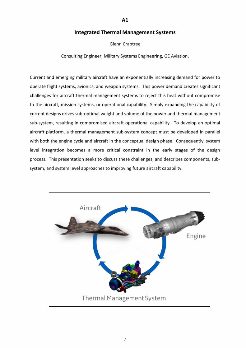
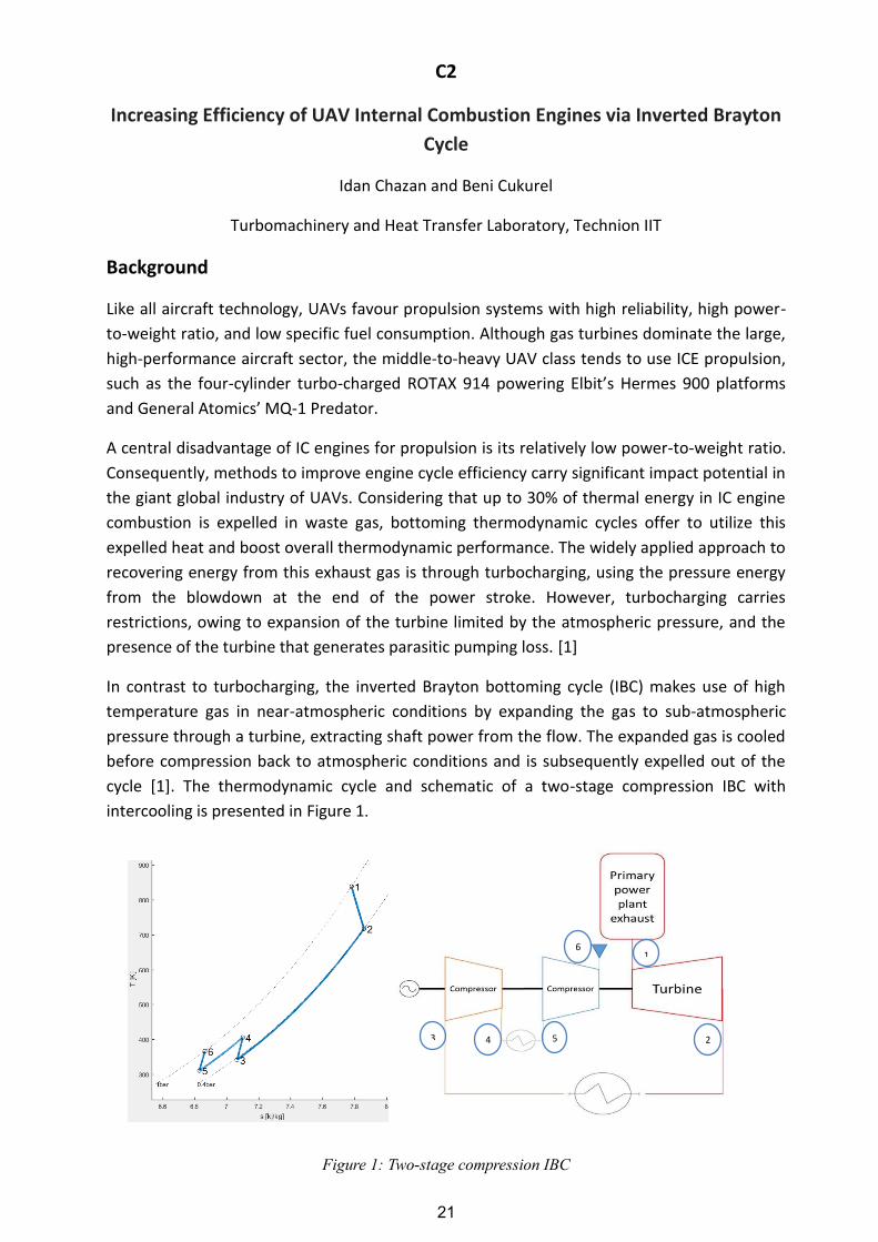
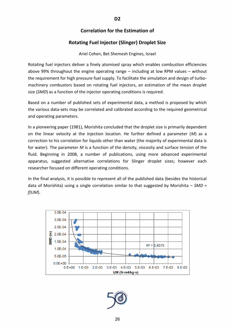
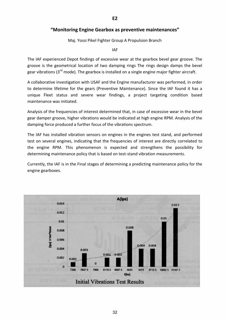