TG8000 Multiformat Test Signal Generator PC Tools ... · The File Copy Tools utility has been...
41
xx TG8000 Multiformat Test Signal Generator PC Tools ZZZ Technical Reference *P077068400* 077-0684-00
Transcript of TG8000 Multiformat Test Signal Generator PC Tools ... · The File Copy Tools utility has been...

xx
TG8000Multiformat Test Signal GeneratorPC Tools
ZZZ
Technical Reference
*P077068400*
077-0684-00


TG8000Multiformat Test Signal GeneratorPC Tools
ZZZ
Technical Reference
xx
This document supports firmware version 1.0 and above.
www.tektronix.com077-0684-00

Copyright © Tektronix. All rights reserved. Licensed software products are owned by Tektronix or its subsidiariesor suppliers, and are protected by national copyright laws and international treaty provisions.
Tektronix products are covered by U.S. and foreign patents, issued and pending. Information in this publicationsupersedes that in all previously published material. Specifications and price change privileges reserved.
TEKTRONIX and TEK are registered trademarks of Tektronix, Inc.
Contacting Tektronix
Tektronix, Inc.14150 SW Karl Braun DriveP.O. Box 500Beaverton, OR 97077USA
For product information, sales, service, and technical support:In North America, call 1-800-833-9200.Worldwide, visit www.tektronix.com to find contacts in your area.

Warranty
Tektronix warrants that this product will be free from defects in materials and workmanship for a period of one (1)year from the date of shipment. If any such product proves defective during this warranty period, Tektronix, at itsoption, either will repair the defective product without charge for parts and labor, or will provide a replacementin exchange for the defective product. Parts, modules and replacement products used by Tektronix for warrantywork may be new or reconditioned to like new performance. All replaced parts, modules and products becomethe property of Tektronix.
In order to obtain service under this warranty, Customer must notify Tektronix of the defect before the expiration ofthe warranty period and make suitable arrangements for the performance of service. Customer shall be responsiblefor packaging and shipping the defective product to the service center designated by Tektronix, with shippingcharges prepaid. Tektronix shall pay for the return of the product to Customer if the shipment is to a location withinthe country in which the Tektronix service center is located. Customer shall be responsible for paying all shippingcharges, duties, taxes, and any other charges for products returned to any other locations.
This warranty shall not apply to any defect, failure or damage caused by improper use or improper or inadequatemaintenance and care. Tektronix shall not be obligated to furnish service under this warranty a) to repair damageresulting from attempts by personnel other than Tektronix representatives to install, repair or service the product;b) to repair damage resulting from improper use or connection to incompatible equipment; c) to repair any damageor malfunction caused by the use of non-Tektronix supplies; or d) to service a product that has been modified orintegrated with other products when the effect of such modification or integration increases the time or difficultyof servicing the product.
THIS WARRANTY IS GIVEN BY TEKTRONIX WITH RESPECT TO THE PRODUCT IN LIEU OF ANYOTHER WARRANTIES, EXPRESS OR IMPLIED. TEKTRONIX AND ITS VENDORS DISCLAIM ANYIMPLIED WARRANTIES OF MERCHANTABILITY OR FITNESS FOR A PARTICULAR PURPOSE.TEKTRONIX' RESPONSIBILITY TO REPAIR OR REPLACE DEFECTIVE PRODUCTS IS THE SOLEAND EXCLUSIVE REMEDY PROVIDED TO THE CUSTOMER FOR BREACH OF THIS WARRANTY.TEKTRONIX AND ITS VENDORS WILL NOT BE LIABLE FOR ANY INDIRECT, SPECIAL, INCIDENTAL,OR CONSEQUENTIAL DAMAGES IRRESPECTIVE OF WHETHER TEKTRONIX OR THE VENDOR HASADVANCE NOTICE OF THE POSSIBILITY OF SUCH DAMAGES.
[W2 – 15AUG04]


Table of Contents
General safety summary .. . . . . . . . . . . . . . . . . . . . . . . . . . . . . . . . . . . . . . . . . . . . . . . . . . . . . . . . . . . . . . . . . . . . . . . . . . . . . . . . . . . . . . . . . iv
Preface .. . . . . . . . . . . . . . . . . . . . . . . . . . . . . . . . . . . . . . . . . . . . . . . . . . . . . . . . . . . . . . . . . . . . . . . . . . . . . . . . . . . . . . . . . . . . . . . . . . . . . . . . . . . . vii
Products . . . . . . . . . . . . . . . . . . . . . . . . . . . . . . . . . . . . . . . . . . . . . . . . . . . . . . . . . . . . . . . . . . . . . . . . . . . . . . . . . . . . . . . . . . . . . . . . . . . . . . . vii
PC Tools . . . . . . . . . . . . . . . . . . . . . . . . . . . . . . . . . . . . . . . . . . . . . . . . . . . . . . . . . . . . . . . . . . . . . . . . . . . . . . . . . . . . . . . . . . . . . . . . . . . . . . vii
Differences between the TG700 and TG8000 mainframes .. . . . . . . . . . . . . . . . . . . . . . . . . . . . . . . . . . . . . . . . . . . . viii
PC system requirements. . . . . . . . . . . . . . . . . . . . . . . . . . . . . . . . . . . . . . . . . . . . . . . . . . . . . . . . . . . . . . . . . . . . . . . . . . . . . . . . . . . . . viii
Product documentation. . . . . . . . . . . . . . . . . . . . . . . . . . . . . . . . . . . . . . . . . . . . . . . . . . . . . . . . . . . . . . . . . . . . . . . . . . . . . . . . . . . . . . . ix
Using TG Setup to set parameters . . . . . . . . . . . . . . . . . . . . . . . . . . . . . . . . . . . . . . . . . . . . . . . . . . . . . . . . . . . . . . . . . . . . . . . . . . . . . . . . 1
Installation instructions and Ethernet setup .. . . . . . . . . . . . . . . . . . . . . . . . . . . . . . . . . . . . . . . . . . . . . . . . . . . . . . . . . . . . . . . . 1
Starting and exiting TG Setup . . . . . . . . . . . . . . . . . . . . . . . . . . . . . . . . . . . . . . . . . . . . . . . . . . . . . . . . . . . . . . . . . . . . . . . . . . . . . . . . 3
Elements of the TG Setup window .. . . . . . . . . . . . . . . . . . . . . . . . . . . . . . . . . . . . . . . . . . . . . . . . . . . . . . . . . . . . . . . . . . . . . . . . . 3
Using the TG Setup menus .. . . . . . . . . . . . . . . . . . . . . . . . . . . . . . . . . . . . . . . . . . . . . . . . . . . . . . . . . . . . . . . . . . . . . . . . . . . . . . . . . . 4
TG Setup tutorial. . . . . . . . . . . . . . . . . . . . . . . . . . . . . . . . . . . . . . . . . . . . . . . . . . . . . . . . . . . . . . . . . . . . . . . . . . . . . . . . . . . . . . . . . . . . . . . 6
Using Frame Picture Generator . . . . . . . . . . . . . . . . . . . . . . . . . . . . . . . . . . . . . . . . . . . . . . . . . . . . . . . . . . . . . . . . . . . . . . . . . . . . . . . . . . . 9
Installation instructions . . . . . . . . . . . . . . . . . . . . . . . . . . . . . . . . . . . . . . . . . . . . . . . . . . . . . . . . . . . . . . . . . . . . . . . . . . . . . . . . . . . . . . . 9
Starting and exiting Frame Picture Generator . . . . . . . . . . . . . . . . . . . . . . . . . . . . . . . . . . . . . . . . . . . . . . . . . . . . . . . . . . . . . 10
Elements of the Frame Picture Generator window.. . . . . . . . . . . . . . . . . . . . . . . . . . . . . . . . . . . . . . . . . . . . . . . . . . . . . . . 11
Using the Frame Picture Generator menus. . . . . . . . . . . . . . . . . . . . . . . . . . . . . . . . . . . . . . . . . . . . . . . . . . . . . . . . . . . . . . . . . 13
Frame Picture Generator tutorials. . . . . . . . . . . . . . . . . . . . . . . . . . . . . . . . . . . . . . . . . . . . . . . . . . . . . . . . . . . . . . . . . . . . . . . . . . . 15
Using Logo Generator . . . . . . . . . . . . . . . . . . . . . . . . . . . . . . . . . . . . . . . . . . . . . . . . . . . . . . . . . . . . . . . . . . . . . . . . . . . . . . . . . . . . . . . . . . . . 17
Installation instructions . . . . . . . . . . . . . . . . . . . . . . . . . . . . . . . . . . . . . . . . . . . . . . . . . . . . . . . . . . . . . . . . . . . . . . . . . . . . . . . . . . . . . . 17
Starting and exiting Logo Generator. . . . . . . . . . . . . . . . . . . . . . . . . . . . . . . . . . . . . . . . . . . . . . . . . . . . . . . . . . . . . . . . . . . . . . . . 18
Elements of the Logo Generator window .. . . . . . . . . . . . . . . . . . . . . . . . . . . . . . . . . . . . . . . . . . . . . . . . . . . . . . . . . . . . . . . . . 19
Using the Logo Generator menus . . . . . . . . . . . . . . . . . . . . . . . . . . . . . . . . . . . . . . . . . . . . . . . . . . . . . . . . . . . . . . . . . . . . . . . . . . . 20
Logo Generator tutorials . . . . . . . . . . . . . . . . . . . . . . . . . . . . . . . . . . . . . . . . . . . . . . . . . . . . . . . . . . . . . . . . . . . . . . . . . . . . . . . . . . . . . 23
Index
TG8000 Multiformat Test Signal Generator PC Tools Technical Reference i

Table of Contents
List of Figures
Figure 1: Ethernet dialog box for TG Setup .. . . . . . . . . . . . . . . . . . . . . . . . . . . . . . . . . . . . . . . . . . . . . . . . . . . . . . . . . . . . . . . . . . . . 2
Figure 2: TG Setup application window .. . . . . . . . . . . . . . . . . . . . . . . . . . . . . . . . . . . . . . . . . . . . . . . . . . . . . . . . . . . . . . . . . . . . . . . . 3
Figure 3: Rename dialog box .. . . . . . . . . . . . . . . . . . . . . . . . . . . . . . . . . . . . . . . . . . . . . . . . . . . . . . . . . . . . . . . . . . . . . . . . . . . . . . . . . . . . 5
Figure 4: Setup window for DVG7 module . . . . . . . . . . . . . . . . . . . . . . . . . . . . . . . . . . . . . . . . . . . . . . . . . . . . . . . . . . . . . . . . . . . . . 6
Figure 5: Setup window for SDI7 module. . . . . . . . . . . . . . . . . . . . . . . . . . . . . . . . . . . . . . . . . . . . . . . . . . . . . . . . . . . . . . . . . . . . . . . 8
Figure 6: Frame Picture Generator application window .. . . . . . . . . . . . . . . . . . . . . . . . . . . . . . . . . . . . . . . . . . . . . . . . . . . . . 11
Figure 7: BUILDING PIC FILES dialog box .. . . . . . . . . . . . . . . . . . . . . . . . . . . . . . . . . . . . . . . . . . . . . . . . . . . . . . . . . . . . . . . . . 15
Figure 8: Logo Generator application window.. . . . . . . . . . . . . . . . . . . . . . . . . . . . . . . . . . . . . . . . . . . . . . . . . . . . . . . . . . . . . . . . 19
Figure 9: Gray Scale Settings dialog box . . . . . . . . . . . . . . . . . . . . . . . . . . . . . . . . . . . . . . . . . . . . . . . . . . . . . . . . . . . . . . . . . . . . . . . 21
Figure 10: Miscellaneous Settings dialog box . . . . . . . . . . . . . . . . . . . . . . . . . . . . . . . . . . . . . . . . . . . . . . . . . . . . . . . . . . . . . . . . . 22
Figure 11: BMP to LGO File Conversion dialog box . . . . . . . . . . . . . . . . . . . . . . . . . . . . . . . . . . . . . . . . . . . . . . . . . . . . . . . . . 23
ii TG8000 Multiformat Test Signal Generator PC Tools Technical Reference

Table of Contents
List of Tables
Table i: TG8000 product documentation . . . . . . . . . . . . . . . . . . . . . . . . . . . . . . . . . . . . . . . . . . . . . . . . . . . . . . . . . . . . . . . . . . . . . . . ix
Table 1: Elements of the TG Setup window.. . . . . . . . . . . . . . . . . . . . . . . . . . . . . . . . . . . . . . . . . . . . . . . . . . . . . . . . . . . . . . . . . . . . 4
Table 2: TG Setup File menu commands . . . . . . . . . . . . . . . . . . . . . . . . . . . . . . . . . . . . . . . . . . . . . . . . . . . . . . . . . . . . . . . . . . . . . . . . 4
Table 3: Elements of the Frame Picture Generator window .. . . . . . . . . . . . . . . . . . . . . . . . . . . . . . . . . . . . . . . . . . . . . . . . . 11
Table 4: Toolbar button descriptions . . . . . . . . . . . . . . . . . . . . . . . . . . . . . . . . . . . . . . . . . . . . . . . . . . . . . . . . . . . . . . . . . . . . . . . . . . . . 12
Table 5: Frame Picture Generator File menu commands . . . . . . . . . . . . . . . . . . . . . . . . . . . . . . . . . . . . . . . . . . . . . . . . . . . . . 13
Table 6: Frame Picture File Build menu commands. . . . . . . . . . . . . . . . . . . . . . . . . . . . . . . . . . . . . . . . . . . . . . . . . . . . . . . . . . . 13
Table 7: Frame Picture Generator Settings menu commands. . . . . . . . . . . . . . . . . . . . . . . . . . . . . . . . . . . . . . . . . . . . . . . . . 14
Table 8: Elements of the Logo Generator window .. . . . . . . . . . . . . . . . . . . . . . . . . . . . . . . . . . . . . . . . . . . . . . . . . . . . . . . . . . . 19
Table 9: Toolbar button descriptions . . . . . . . . . . . . . . . . . . . . . . . . . . . . . . . . . . . . . . . . . . . . . . . . . . . . . . . . . . . . . . . . . . . . . . . . . . . . 20
Table 10: Logo Generator File menu commands .. . . . . . . . . . . . . . . . . . . . . . . . . . . . . . . . . . . . . . . . . . . . . . . . . . . . . . . . . . . . . 20
Table 11: Logo Generator Build menu commands .. . . . . . . . . . . . . . . . . . . . . . . . . . . . . . . . . . . . . . . . . . . . . . . . . . . . . . . . . . . 20
Table 12: Logo Generator Settings menu commands . . . . . . . . . . . . . . . . . . . . . . . . . . . . . . . . . . . . . . . . . . . . . . . . . . . . . . . . . 21
Table 13: Logo Generator Help menu command .. . . . . . . . . . . . . . . . . . . . . . . . . . . . . . . . . . . . . . . . . . . . . . . . . . . . . . . . . . . . . 22
TG8000 Multiformat Test Signal Generator PC Tools Technical Reference iii

General safety summary
General safety summaryReview the following safety precautions to avoid injury and prevent damage tothis product or any products connected to it.
To avoid potential hazards, use this product only as specified.
Only qualified personnel should perform service procedures.
To avoid fire or personalinjury
Use proper power cord. Use only the power cord specified for this product andcertified for the country of use.
Ground the product. This product is grounded through the grounding conductorof the power cord. To avoid electric shock, the grounding conductor must beconnected to earth ground. Before making connections to the input or outputterminals of the product, ensure that the product is properly grounded.
Observe all terminal ratings. To avoid fire or shock hazard, observe all ratingsand markings on the product. Consult the product manual for further ratingsinformation before making connections to the product.
Power disconnect. The power cord disconnects the product from the power source.Do not block the power cord; it must remain accessible to the user at all times.
Do not operate without covers. Do not operate this product with covers or panelsremoved.
Do not operate with suspected failures. If you suspect that there is damage to thisproduct, have it inspected by qualified service personnel.
Avoid exposed circuitry. Do not touch exposed connections and components whenpower is present.
Do not operate in wet/damp conditions.
Do not operate in an explosive atmosphere.
Keep product surfaces clean and dry.
Provide proper ventilation. Refer to the manual's installation instructions for detailson installing the product so it has proper ventilation.
iv TG8000 Multiformat Test Signal Generator PC Tools Technical Reference

General safety summary
Terms in this manual These terms may appear in this manual:
WARNING. Warning statements identify conditions or practices that could resultin injury or loss of life.
CAUTION. Caution statements identify conditions or practices that could result indamage to this product or other property.
Symbols and terms on theproduct
These terms may appear on the product:
DANGER indicates an injury hazard immediately accessible as you readthe marking.
WARNING indicates an injury hazard not immediately accessible as youread the marking.
CAUTION indicates a hazard to property including the product.
The following symbol(s) may appear on the product:
TG8000 Multiformat Test Signal Generator PC Tools Technical Reference v

General safety summary
vi TG8000 Multiformat Test Signal Generator PC Tools Technical Reference

PrefaceThis manual provides information about various PC tools that can be used withthe TG8000 Multiformat Test Signal Generator and related modules.
ProductsThe information in this manual applies to the following products:
TG8000 Multiformat Test Signal Generator
AG7 Audio Generator Module
AGL7 Analog Genlock Module
ATG7 Analog Test Generator Module
AVG7 Analog Video Generator Module
AWVG7 Analog Wideband Video Generator Module
BG7 Black Generator Module
DVG7 Digital Video Generator Module
GPS7 GPS Synchronization and Timecode Module
HDLG7 HD Dual Link Generator Module
HDVG7 HDTV Digital Video Generator Module
HD3G7 HD 3 Gb/s SDI Video Generator Module
SDI7 Dual Channel SD/HD/3G SDI Video Generator Module
PC ToolsThe following utilities and software applications are described in this manual:
TG Setup
Frame Picture Generator
Logo Generator
TG8000 Multiformat Test Signal Generator PC Tools Technical Reference vii

Preface
Differences between the TG700 and TG8000 mainframesThe firmware upgrade procedure for the TG8000 is different from the TG700 andis described below. In addition, the PC Tools software for the TG700 mainframeincluded TG7Comm for transferring signal files and File Copy Tools for backingup and restoring presets and all user files. For the TG8000 mainframe, those twosoftware tools have been replaced as described below:
The TG7Comm utility was replaced by use of FTP to transfer signal filesbetween a PC and the TG8000 mainframe.
The File Copy Tools utility has been replaced by using a USB drive to backupand restore presets and all user data.
Firmware upgrades on the TG8000 mainframe can now be performed using aUSB drive or a network connection.
NOTE. Refer to the TG8000 Multiformat Test Signal Generator User Manual forinstructions on how to perform these tasks.
PC system requirementsEach application described in this manual requires the following minimum systemrequirements:
Microsoft Windows XP or Windows 7
The TG Setup tools require the following since they interact directly with theinstrument:
Ethernet interface
The Frame Picture Generator requires the following:
True Color (more than 24 bits) display mode
viii TG8000 Multiformat Test Signal Generator PC Tools Technical Reference

Preface
Product documentationThe following table lists the user documents for the TG8000 and its relatedmodules:
Table i: TG8000 product documentation
Availability
Document Tektronix Part Number Description Print Web CD
User Manual 071-3036-xx (English)
071-3037-xx (Japanese)
071-3038-xx (Russian)
Describes how to install, operate, andconfigure the instrument
PC Tools Technical Reference 077-0684-xx Describes how to use the PC tools softwarethat is supplied with the instrument
Specifications andPerformance Verification
077-0685-xx Lists the product specifications andprovides procedures for verifying theperformance of the instrument
Programmer Manual 077-0686-xx Provides programming information for themainframe and related modules
Service Manual 077-0687-xx Describes how to service the mainframe tothe module level (such as circuit boardsand fuses) and provides information aboutservicing generator modules
Declassification and SecurityInstructions
077-0688-xx Describes how to clear or sanitize the datastorage (memory) devices in the productfor customers with data security concerns.
Release Notes 077-0689-xx Describes the new features, improvements,and limitations of the instrument firmware
Video Sync Pulse Generatorand Electronic ChangeoverUnit System IntegrationTechnical Reference
077-0563-xx Provides information for systemintegrators who are designing systems forhigh-definition (HD) and standard-definition(SD) digital video content where Tektronixelectronic changeover units and videosync pulse generators are to be deployed.
TG8000 Multiformat Test Signal Generator PC Tools Technical Reference ix

Preface
x TG8000 Multiformat Test Signal Generator PC Tools Technical Reference

Using TG Setup to set parametersTG Setup, a standard accessory with the TG8000, is a software application fora PC using the Microsoft Windows operating system. TG Setup provides thecapability to set all of the parameters of the TG8000 mainframe and installedmodules using a PC.
This section provides the following information:
Installation instructions and Ethernet setup
Starting and exiting TG Setup
Elements of the TG Setup window
Using the TG Setup menus
TG Setup tutorial
Installation instructions and Ethernet setupThis subsection contains instructions to install and configure the TG Setupapplication on your PC.
Installing TG Setup The following installation instructions require that you are familiar with the basicsof using the Windows operating system.
Perform the following procedure to install TG Setup software:
1. Be sure that your PC meets the requirements before proceeding with theinstallation. (See page viii, PC system requirements.)
2. Insert the TG700 and TG8000 SW Library and Documentation DVD(063-4440-XX) into a DVD drive on your PC.
3. When the Product Software and Documentation Browser window appears,select the TG7 Tools Software link.
4. Select the TG Setup link to install the software. Follow the on-screeninstructions to complete the software installation.
Creating a desktopshortcut icon
Perform the following procedure to create an icon on your PC desktop that youcan use to run the TG Setup application.
1. On your PC display, right click to open the desktop menu.
2. Use the New > Shortcut command to create a shortcut to the TGSetup.exefile.
3. You can start the TG Setup application by double-clicking the shortcut icon.
TG8000 Multiformat Test Signal Generator PC Tools Technical Reference 1

Using TG Setup to set parameters
Connecting your PC(s) tothe instrument
TG Setup uses the rear-panel 10/100/1000 BASE-T port on the instrument tocommunicate with a PC.
Refer to the TG8000 Multiformat Test Signal Generator User Manual (Tektronixpart number 071-3036-XX) for detailed information about how to connect yourPC(s) to the instrument.
Setting Ethernet networkparameters
Before you can use TG Setup to set the parameters of the instrument mainframeand installed modules, you must set the Ethernet network parameters for both theinstrument and the TG Setup application.
NOTE. Use the ping command from the PC to verify network communicationsafter you set the Ethernet network parameters for the instrument and for theTG Setup application.
Ethernet parameters for the TG8000. The Ethernet network parameters for theTG8000 can be set using the NETWORK SETUP submenu in the UTILITYmain menu. Refer to Setting Ethernet Network Parameters in the TG8000 usermanual for detailed information about how to set the network parameters.
Ethernet parameters for TG Setup. When you start the TG Setup application, theEthernet dialog box appears as shown in the following figure. Use this dialog boxto set the Ethernet network parameters for the TG Setup application.
Figure 1: Ethernet dialog box for TG Setup
Perform the following procedure to set the Ethernet network parameters for theTG Setup application:
1. Use the IP Address field in the dialog box to enter the IP address that youassigned to the TG8000.
2. Click the OK button to accept the settings and close the dialog box.
2 TG8000 Multiformat Test Signal Generator PC Tools Technical Reference

Using TG Setup to set parameters
Starting and exiting TG SetupWhen you complete the installation procedure, you can use any of the followingmethods to start the TG Setup application:
Double-click the TGSetup.exe shortcut icon on the PC desktop that youcreated during the installation procedure.
Double-click the TGSetup.exe file name in the Program Manager window.
Select TGSetup from the Start - Programs menu.
To exit the TG Setup application, select File > Exit in the application window.
NOTE. When you start the TG Setup application, the TG8000 front-panel aredisabled once the application window appears. (See Figure 2.)
Elements of the TG Setup windowThe following figure shows the TG Setup application window. For description ofthe elements in the application window refer to the following table.
Figure 2: TG Setup application window
TG8000 Multiformat Test Signal Generator PC Tools Technical Reference 3

Using TG Setup to set parameters
Table 1: Elements of the TG Setup window
Element Description
Title bar The Title bar displays the name of the application and containsthe standard window-sizing boxes for Windows.
Menu bar The Menu bar displays the names of the four pull-down menus.(See page 4, Using the TG Setup menus.)
Setup window Use the Setup window to set the parameters for the installedmodules or mainframe. This window appears after you selectthe Open Module or Open TG Instrument command from theFile pull-down menu.
Status bar The Status bar displays the short explanation of the currentlyselected command and the information related to the operation.
Using the TG Setup menusThe Menu bar displays the names of the four pull-down menus: File, View,Window, and Help. This section describes the function of each selection in thesemenus.
File menu The File menu contains commands for opening a setup window, for managingpreset operations, and for exiting the TG Setup application. The followingdescribes each of the File menu commands.
Table 2: TG Setup File menu commands
Command Function
Open TG Instrument Opens the setup window for the mainframe.
Open Module Opens the setup window for the selected module.
Recall Preset Recalls the selected preset.
Save Preset Saves the current instrument settings to the selected preset.
Rename Preset Renames the selected preset name. When you select thiscommand, the Rename dialog box appears. (See page 5,Rename dialog box.)
Exit Exits the TG Setup application.
4 TG8000 Multiformat Test Signal Generator PC Tools Technical Reference

Using TG Setup to set parameters
Rename dialog box. The Rename dialog box (following figure) appears after youselect the Rename Preset command. You can use this box to assign a new nameto the selected preset.
Figure 3: Rename dialog box
View menu The View menu Status Bar command toggles the display of the Status bar on andoff in the application window. A check mark precedes the command in the menuwhen the Status bar is selected for display.
Window menu The Window menu commands (Cascade, Tile, and Arrange Icons) control theappearance of the setup windows in the application window. Use Arrange Iconswhen the setup windows are minimized.
Help menu The Help menu About TGSetup... command displays information including theTG Setup software version number and copyright information.
TG8000 Multiformat Test Signal Generator PC Tools Technical Reference 5

Using TG Setup to set parameters
TG Setup tutorialAfter you have connected the TG8000 to the PC using an Ethernet cable and setthe required network parameters, you can use TG Setup to do the following:
Set the parameters for the TG8000 mainframe and installed modules. (Seepage 6, Setting parameters.)
Enter an option key for an SDI7 module, if you have an SDI7 module and havepurchased Option 3G. (See page 8, Entering the option key for Option 3G.)
NOTE. Refer to the Operating Basics section of each module's User manual fordetailed explanation of the parameters and their setting ranges.
Setting parameters This subsection explains how to set the parameters of an installed module. In thisexample, you will set the parameters for the DVG7 module.
Perform the following steps to set parameters:
1. Select File > Open Module > DVG7 to open the setup window for theDVG7 module as shown in the following figure.
Figure 4: Setup window for DVG7 module
At the top of the setup window, there are several tabs to select parameters. Whenyou click one of the tabs, you access the fields associated with that parameter. Inthis example, the Signal tab is selected and the fields for setting the signal format,signal set, output signal, frame picture, and timing are displayed.
6 TG8000 Multiformat Test Signal Generator PC Tools Technical Reference

Using TG Setup to set parameters
When you change any parameter in the window, the Apply button at the bottomof the window becomes active. Press this button to enable the new parametersettings.
2. Click the tab associated with the parameter you want to set. This opens theparameter fields for that tab.
3. Set parameters in the displayed fields.
4. Repeat Steps 2 and 3 until all of the parameter settings are completed.
5. When you finish making changes to the parameters, click the Apply button.This enables the parameter settings in the setup window and transfers themto the TG8000.
NOTE. If you select a signal file or a picture file that is not assigned to a testsignal button on the TG8000 front panel, an error message appears when youclick the Apply button. If this happens, you need to assign the file to a test signalbutton. Refer to SIGNAL KEY ASSIGN Submenu in the TG8000 user manualfor more information.
When you change parameters for a module, that module is selected in the TG8000,regardless of what is shown on the display. To prevent addressing the wrongmodule from the front panel after you exit TG Setup, first select any of the modulesusing the MODULE button and then make settings.
TG8000 Multiformat Test Signal Generator PC Tools Technical Reference 7

Using TG Setup to set parameters
Entering the option key forOption 3G
This subsection explains how to enable Option 3G for an installed SDI7 moduleby entering the option key. To complete this procedure, you must have purchasedOption 3G and received an option key. The option key is a code consisting of acombination of letters and numbers that will enable Option 3G for your SDI7module.
In this example, it is assumed that you are enabling the option for the first time.
1. Select File > Open Module > SDI7 to open the setup window for theSDI7 module as shown in the following figure.
Figure 5: Setup window for SDI7 module
At the top of the setup window, there are eight tabs. The Status tab windowcontains two sections. The top section contains information about the signal.The bottom section contains diagnostics information, the module ID, andoption information.
When you first open the Status tab window, the Option Key field will containan option key if there is already one enabled, or a series of dashes if there isno option enabled. The line below the option key field shows you whichoptions, if any, are enabled.
2. Click in the option key field and enter the option key you purchased.
3. Click the Update button to enable the option.
8 TG8000 Multiformat Test Signal Generator PC Tools Technical Reference

Using Frame Picture Generator
Using Frame Picture GeneratorThe Frame Picture Generator application is used only with the following modules:
AVG7 Analog Video Generator Module
AWVG7 Analog Wideband Video Generator Module
DVG7 Digital Video Generator Module
HDVG7 HDTV Digital Video Generator Module
Frame Picture Generator is a software application for a PC using the MicrosoftWindows system. Frame Picture Generator provides the capability to convert aWindows bitmap file (.bmp) to a frame picture file (.pic) that can be used by theTG8000. Using this application, you can convert a natural picture or a test patternin bitmap format to a frame picture file and output it as a picture.
This section provides the following information:
Installation instructions
Starting and exiting Frame Picture Generator
Elements of the Frame Picture Generator window
Using the Frame Picture Generator menus
Frame Picture Generator tutorials
Installation instructionsThis subsection provides instructions to install the Frame Picture Generatorapplication on your PC.
Installing Frame PictureGenerator
The following installation instructions require that you are familiar with the basicsof using the Windows operating system. If necessary, read your Windows userdocumentation before installing Frame Picture Generator.
Perform the following procedure to install the Frame Picture Generator:
1. Be sure that your PC meets the requirements before proceeding with theinstallation. (See page viii, PC system requirements.)
2. Insert the TG8000 Multiformat Test Signal Generator SW Library andDocumentation DVD (063-4440-XX) into a DVD drive on your PC.
3. When the Product Software and Documentation Browser window appears,select the TG7 Tools Software link.
4. Select the Frame Picture Generator link to install the software. Follow theon-screen instructions to complete the software installation.
TG8000 Multiformat Test Signal Generator PC Tools Technical Reference 9

Using Frame Picture Generator
Creating a desktopshortcut icon
Perform the following procedure to create an icon on your PC desktop that youcan use to run the Frame Picture Generator application.
1. On your PC display, right click to open the desktop menu.
2. Use the New > Shortcut command to create a shortcut to the FrameGEN.exefile.
3. You can start the TG7 Frame Picture Generator application by double-clickingthe shortcut icon.
Starting and exiting Frame Picture GeneratorWhen you complete the installation procedure, you can use any of the followingmethods to start the Frame Picture Generator application:
Double-click the FrameGEN.exe shortcut icon on the PC desktop that youcreated during the installation procedure.
Double-click the FrameGEN.exe file name in the Program Manager window.
Select FrameGen from the Start - Programs menu.
To exit the Frame Picture Generator application, select File > Exit in theapplication window.
10 TG8000 Multiformat Test Signal Generator PC Tools Technical Reference

Using Frame Picture Generator
Elements of the Frame Picture Generator windowThe following figure shows the Frame Picture Generator application window. Fordescription of the elements in the application window, refer to the following table.
Figure 6: Frame Picture Generator application window
Table 3: Elements of the Frame Picture Generator window
Element Description
Title bar The Title bar displays the name of the application and containsthe standard window-sizing boxes for Windows.
Menu bar The Menu bar displays the names of the five pull-down menus.(See page 13, Using the Frame Picture Generator menus.).
Toolbar The Toolbar provides shortcut buttons for many of the mostoften used menu commands. Click a toolbar button to select thecorresponding command. (See Table 4.)
BMP View window The BMP View window displays the selected bitmap imagebefore conversion.
FrameBMP View window The FrameBMP View window displays the frame bitmap imageconverted to the specified video format size.
PicBMP View window The PicBMP View window displays the frame picture imageconverted to the bitmap file.
TG8000 Multiformat Test Signal Generator PC Tools Technical Reference 11

Using Frame Picture Generator
Table 4: Toolbar button descriptions
Icon Name Function
Open Equivalent to the Opencommand in the File menu.
Save Frame Bmp As Equivalent to the SaveFrame BmpAs command inthe File menu.
Save Pic Bmp As Equivalent to the Save PicBmpAs command in theFile menu.
Build Frame Bmp Equivalent to the BuildFrame Bmp command inthe Build menu.
Build Pic File Equivalent to the Build PicFile command in the Buildmenu.
Build Pic Bmp Equivalent to the Build PicBmp command in the Buildmenu.
Cascade Equivalent to the Cascadecommand in the Windowmenu.
Horizontal Equivalent to the Horizontalcommand in the Windowmenu.
Vertical Equivalent to the Verticalcommand in the Windowmenu.
Exit Equivalent to the Exitcommand in the File menu.
12 TG8000 Multiformat Test Signal Generator PC Tools Technical Reference

Using Frame Picture Generator
Using the Frame Picture Generator menusThe Menu bar displays the names of the five pull-down menus: File, Build,Settings, Window, and Help. This section describes the function of each selectionin these menus.
File menu The File menu contains commands for managing file operations and for exitingthe Frame Picture Generator application. The following table describes eachof the File menu commands.
Table 5: Frame Picture Generator File menu commands
Command Function
Open Opens a bitmap file. When you select a bitmap file, the image isdisplayed in the BMP View window.
Save Frame Bmp As Saves the frame bitmap image displayed in the FrameBMPView window as a bitmap file.
Save Pic Bmp As Saves the frame picture image displayed in the PicBMP Viewwindow as a bitmap file.
Exit Exits the Frame Picture Generator application.
Build menu The Build menu contains commands that create a frame bitmap file or framepicture file and convert a frame picture file to a bitmap file. The following tabledescribes each of the Build menu commands.
Table 6: Frame Picture File Build menu commands
Command Function
Build Frame Bmp Converts the bitmap image displayed in the BMP View windowto the bitmap file with the specified video format size.
Build Pic File Converts the frame bitmap file displayed in the FrameBMP Viewwindow to the frame picture file (.pic) that can be used by theTG8000.
Since the AVG7 module outputs a signal using the 2-time oversampling technique, one pixel of a bitmap image correspondsto two samples of the signal. Therefore, when creating a framepicture file for the AVG7 module, the application uses each pixelof a bitmap image twice.
Build Pic Bmp Converts the selected frame picture file (.pic) to the bitmapfile and displays its image in the PicBMP View window. Notethat this command cannot reproduce the original bitmap filecompletely because the data of the frame picture file is changedwhen it is converted from the bitmap file. This command is usefulwhen you want to check any frame picture images on the PC.
TG8000 Multiformat Test Signal Generator PC Tools Technical Reference 13

Using Frame Picture Generator
Settings menu The Settings menu contains commands for setting the video format size andbackground color. The following table describes each of the Settings menucommands.
Table 7: Frame Picture Generator Settings menu commands
Command Function
Background Specifies the color used for the background of the bitmap image.
Filter Eliminates unnecessary high frequency components containedin the bitmap image. These high frequency components derivefrom rapid changes of intensity or hue in the image generatedby using a graphic program. This command is only available forthe video format sizes of the DVG7 and HDVG7.
Format Specifies the video format size when the frame bitmap iscreated.
Window menu The Window commands control the appearance of the view windows. UseArrange Icon when the windows are minimized.
Help menu The Help menu About FrameGen command displays the Frame Picture Generatorsoftware version number and copyright information.
14 TG8000 Multiformat Test Signal Generator PC Tools Technical Reference

Using Frame Picture Generator
Frame Picture Generator tutorialsThis subsection describes the basics of operating the Frame Picture Generatorapplication.
Creating a frame picturefile
Perform the following steps to create a frame picture file (.pic) from a Windowsbitmap file (.bmp).
1. Select File > Open.
2. Select the bitmap file on the PC that you want to convert, and then click theOpen button. This will display the bitmap image in the BMP View window.
3. Select Settings > Background to specify the background color for the framebitmap.
4. Select Settings > Format to select the video format size when the framebitmap is created.
5. Select Build > Build Frame Bmp. This will display the frame bitmap imageconverted to the specified video format size in the FrameBMP View window.
6. Select Build > Build Pic File to convert the frame bitmap file to the framepicture file. While the conversion is in progress, the BUILDING PIC FILESdialog box shown in the following figure appears.
Figure 7: BUILDING PIC FILES dialog box
7. When the file conversion is completed, the Pic File dialog box appears.
8. In the dialog box specify the destination folder where you want to save theframe picture file, and the file name.
9. Click the Save button to save the file.
TG8000 Multiformat Test Signal Generator PC Tools Technical Reference 15

Using Frame Picture Generator
Downloading a framepicture file and outputting
the picture
A frame picture file created by Frame Picture Generator is output as a picture bydownloading to the TG8000. Procedures for downloading images can be foundin the TG8000 user manual.
NOTE. Make sure to download a frame picture file to a folder for a generatormodule that can output the correct video format for the frame picture. If thevideo format for the frame picture file is different from the video format for thegenerator module, the picture is not output correctly.
Flash memory capacity. View the total amount of flash memory that is installedin the mainframe and view the amount of free (available) memory from theUTILITY > FLASH MEMORY menu. There are approximately 80 MB total offlash memory available. The flash memory is used by the test signal files that youinstall in the mainframe. When the amount of available memory is low, you mayneed to delete test signals from memory before you can install new test signals.
NOTE. The flash memory of the TG8000 is shared among system files, test signalfiles, and frame picture files. Therefore, if you use the whole free memory space forframe pictures, system files may not be installed when upgrading the instrument,or additional test signals may not be installed.
If you have more pictures to be output, you can output them by saving anotherfolder and then assigning it to the front-panel button.
NOTE. See the TG8000 Multiformat Test Signal Generator User Manual forprocedures for downloading picture files from a PC to the TG8000.
Outputting the picture. Perform the following steps to output the frame picturefile as a picture.
1. Assign the frame picture file to the OTHER test signal button on the frontpanel.
Refer to the SIGNAL KEY ASSIGN Submenu in the TG8000 user manualabout how to assign a frame picture file to the OTHER test signal button.
2. Press the front-panelMODULE button to select the module from which youwant to output the picture.
3. Press the front-panel FORMAT button to select the video format for theframe picture file.
4. Press the OTHER test signal button.
5. Press the left (◄) or right (►) arrow button, or the OTHER test signal buttonrepeatedly to select the picture that you want to output.
16 TG8000 Multiformat Test Signal Generator PC Tools Technical Reference

Using Logo Generator
Using Logo GeneratorThe Logo Generator application is used only with the following modules:
DVG7 Digital Video Generator Module
HDVG7 HDTV Digital Video Generator Module
Logo Generator is a software application for a PC using the Microsoft Windowssystem. Logo Generator provides the capability to convert a Windows bitmapfile (.bmp) to a logo file (.lgo) that can be used with the logo overlay feature ofthe DVG7 or HDVG7 module.
This section provides the following information:
Installation instructions
Starting and exiting Logo Generator
Elements of Logo Generator window
Using the Logo Generator menus
Logo Generator tutorials
Installation instructionsThis subsection provides instructions to install the Logo Generator applicationon your PC.
Installing Logo Generator The following installation instructions require that you are familiar with the basicsof using the Windows operating system. If necessary, read your Windows userdocumentation before installing Logo Generator.
Perform the following procedure to install the Logo Generator software:
1. Be sure that your PC meets the requirements before proceeding with theinstallation. (See page viii, PC system requirements.)
2. Insert the TG8000 Multiformat Test Signal Generator SW Library andDocumentation DVD into a DVD drive on your PC.
3. When the Product Software and Documentation Browser window appears,select the TG7 Tools Software link.
4. Select the Logo Generator link to install the software. Follow the on-screeninstructions to complete the software installation.
TG8000 Multiformat Test Signal Generator PC Tools Technical Reference 17

Using Logo Generator
Creating a desktopshortcut icon
Perform the following procedure to create an icon on your PC desktop that youcan use to run the Logo Generator application.
1. On your PC display, right click to open the desktop menu.
2. Use the New > Shortcut command to create a shortcut to the Logogen.exefile.
3. You can start the TG Setup application by double-clicking the shortcut icon.
Starting and exiting Logo GeneratorWhen you complete the installation procedure, you can use any of the followingmethods to start the Logo Generator application:
Double-click the Logogen.exe shortcut icon on the PC desktop that youcreated during the installation procedure.
Double-click the Logogen.exe file name in the Program Manager window.
Select LOGOGEN from the Start - Programs menu.
To exit (quit) the Logo Generator application, select File > Exit in the applicationwindow.
18 TG8000 Multiformat Test Signal Generator PC Tools Technical Reference

Using Logo Generator
Elements of the Logo Generator windowThe following figure shows the Logo Generator application window. Fordescription of the elements in the application window, refer to the following table.
Figure 8: Logo Generator application window
Table 8: Elements of the Logo Generator window
Element Description
Title bar The Title bar displays the name of the application and containsthe standard window-sizing boxes for Windows.
Menu bar The Menu bar displays the names of the four pull-downmenus. Refer to Using the Logo Generator Menus for detailedinformation about the menu functions. (See page 20, Using theLogo Generator menus.)
Toolbar The Toolbar provides shortcut buttons for many of the mostoften used menu commands. Click a toolbar button to select thecorresponding command. You can toggle the toolbar display onand off using the Toolbar commands in the Settings pull-downmenu. (See Table 9.)
BMP View The BMP View displays the selected bitmap image.
LGO View The LGO View displays the logo image converted to a grayscale.
Status bar The status bar displays the bitmap size, bits per pixel, andconversion status (%) of the gray scale image.
TG8000 Multiformat Test Signal Generator PC Tools Technical Reference 19
Using Logo Generator
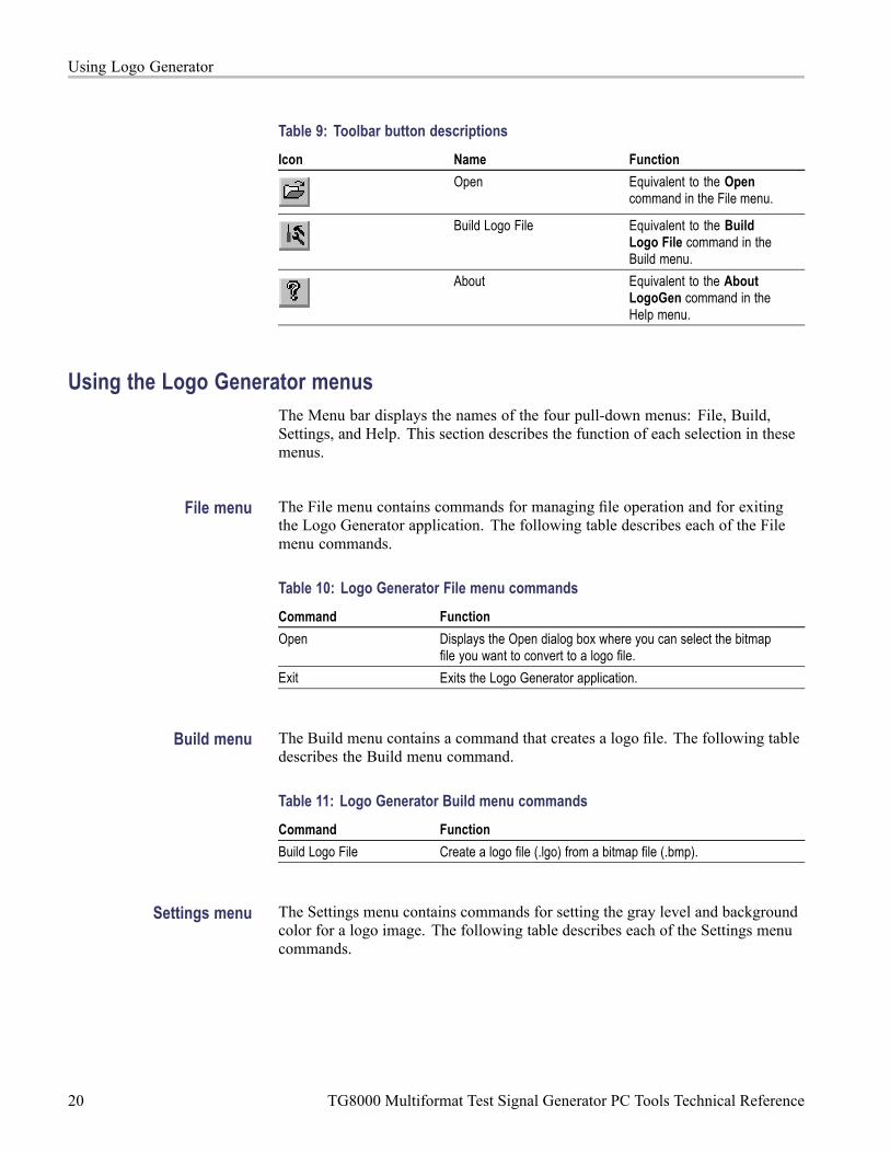
Table 9: Toolbar button descriptions
Icon Name Function
Open Equivalent to the Opencommand in the File menu.
Build Logo File Equivalent to the BuildLogo File command in theBuild menu.
About Equivalent to the AboutLogoGen command in theHelp menu.
Using the Logo Generator menusThe Menu bar displays the names of the four pull-down menus: File, Build,Settings, and Help. This section describes the function of each selection in thesemenus.
File menu The File menu contains commands for managing file operation and for exitingthe Logo Generator application. The following table describes each of the Filemenu commands.
Table 10: Logo Generator File menu commands
Command Function
Open Displays the Open dialog box where you can select the bitmapfile you want to convert to a logo file.
Exit Exits the Logo Generator application.
Build menu The Build menu contains a command that creates a logo file. The following tabledescribes the Build menu command.
Table 11: Logo Generator Build menu commands
Command Function
Build Logo File Create a logo file (.lgo) from a bitmap file (.bmp).
Settings menu The Settings menu contains commands for setting the gray level and backgroundcolor for a logo image. The following table describes each of the Settings menucommands.
20 TG8000 Multiformat Test Signal Generator PC Tools Technical Reference

Using Logo Generator
Table 12: Logo Generator Settings menu commands
Command Function
Gray Level... Sets the gray level when a bitmap image is converted to a logoimage. When you click this command, the Gray Scale Settingsdialog box appears. (See page 21, Gray Scale Settings dialogbox.)
Miscellaneous... Sets a logo name, user comment, and display position. Whenyou click this command, the Miscellaneous Settings dialog boxappears. (See page 22, Miscellaneous Settings dialog box.)
Background Sets the background color.
Toolbar Toggles the display of the Toolbar on and off in the applicationwindow.
Status Bar Toggles the display of the Status bar on and off in the applicationwindow.
Save Settings Specifies whether all the settings are saved.
Gray Scale Settings dialog box. The Gray Scale Settings dialog box (followingfigure) appears after you click the Gray Level command.
Figure 9: Gray Scale Settings dialog box
In this dialog box, you can set the following parameters:
White Limit: Sets the maximum level for the Gray 2 level. The gray scalevalues grater than this value become white level. You can set the value from0 to 255. The default value is 192.
Gray Limit: Sets the maximum level for the Gray 1 level. You can set thevalue from 0 to 255. The default value is 128.
Blanking Limit: Sets the maximum level for the Transparent. You can setthe value from 0 to 255. The default value is 64.
TG8000 Multiformat Test Signal Generator PC Tools Technical Reference 21

Using Logo Generator
Reset Values button resets all of the settings to the values that were in effectwhen the dialog box was first displayed.
Default Values button resets all of the settings to their default values.
Update Display button enables all of the settings with the dialog box opened.
Miscellaneous Settings dialog box. The Miscellaneous Settings dialog box(following figure) appears after you click theMiscellaneous... command.
Figure 10: Miscellaneous Settings dialog box
In this dialog box, you can set the following parameters:
Logo Name: Sets the logo name. This logo name is used when you select alogo from the LOGO OVERLAY submenu of the DVG7 or HDVG7 module.The default logo name is the file name.
Comment: Sets the user comment described in the logo file. You need notenter any comments in general use.
Vertical Position: Sets the vertical position where the logo is displayed on themonitor. You can set the value from -100% to 0%. The vertical position canbe set from the LOGO OVERLAY submenu of the DVG7 or HDVG7 module.
Horizontal Position: Sets the horizontal position where the logo is displayedon the monitor. You can set the value from -100% to 0%. The horizontalposition can be set from the LOGO OVERLAY submenu of the DVG7 orHDVG7 module.
Help menu The Help menu contains a command that displays the Logo Generator applicationversion information. The following table describes the Help menu command.
Table 13: Logo Generator Help menu command
Command Function
About LogoGen... Displays information including the Logo Generator softwareversion number and copyright information.
22 TG8000 Multiformat Test Signal Generator PC Tools Technical Reference

Using Logo Generator
Logo Generator tutorialsThis subsection describes the basics of operating the Logo Generator application.
Creating a logo file Perform the following steps to create a logo file (.lgo) from a Windows bitmapfile (.bmp).
1. Select File > Open.
2. Select the bitmap file on the PC that you want to convert, and then click theOpen button. This will display the bitmap image in the BMP View and thelogo image converted to a gray scale in the LGO View.
3. Select Settings > Gray Level to open the Gray Scale Settings dialog box.(See Figure 9 on page 21.)
4. Set the gray levels for the logo image. You can change the background colorfor the logo image using the Background command.
5. Select Settings > Miscellaneous to open the Miscellaneous Settings dialogbox. (See Figure 10 on page 22.)
6. Set the vertical and horizontal positions for the logo to be displayed on themonitor. If necessary, set the logo name and user comment.
7. Select Build > Build Logo File from the Build pull-down menu to open theBMP to LGO File Conversion dialog box shown in the following figure.
Figure 11: BMP to LGO File Conversion dialog box
8. Click the OK button to create the logo file.
TG8000 Multiformat Test Signal Generator PC Tools Technical Reference 23

Using Logo Generator
24 TG8000 Multiformat Test Signal Generator PC Tools Technical Reference

Index
BBuild menu (Frame Picture
Generator), 13Build menu (Logo Generator), 20
CCreating a frame picture file, 15Creating a logo file, 23
EEthernet
Setup application, 2Exiting the Frame Picture
Generator application, 10Exiting the Logo Generator
application, 18
FFile Copy Tools
replaced by USB, viiiFile menu
Setup application, 4File menu (Frame Picture
Generator), 13File menu (Logo Generator), 20File transfers See see user manualFirmware upgrade See see user
manualUSB and network, viii
Frame Picture Generatorapplication, 9
Frame Picture Generatortutorials, 15
GGray Scale Settings dialog box
(Logo Generator), 21
HHelp menu
Setup application, 5
Help menu (Frame PictureGenerator), 14
Help menu (Logo Generator), 22
IInstalling Frame Picture
Generator, 9Installing Logo Generator, 17
LLogo Generator application, 17Logo Generator tutorials, 23
MManuals
related, ixMiscellaneous Settings dialog box
(Logo Generator), 22
OOption 3G
entering option key, 8
PPC system requirements, viii
RRelated Manuals, ix
SSafety Summary, ivService
manual, ixSettings menu (Frame Picture
Generator), 14Settings menu (Logo
Generator), 20Setup
tutorial, 6
Setup application, 1Ethernet, 2Exiting, 3File menu, 4Help menu, 5installation, 1Starting, 3View menu, 5Window elements, 3Window menu, 5
Starting the Frame PictureGenerator application, 10
Starting the Logo Generatorapplication, 18
TTG Setup application See Setup
applicationTG7Comm
replaced by FTP, viiiTutorial
Setup, 6Tutorials
Frame Picture Generator, 15Logo Generator, 23
UUploading a file to a PC, 16
VView menu
Setup application, 5
WWindow menu
Setup application, 5Window menu (Frame Picture
Generator), 14
TG8000 Multiformat Test Signal Generator PC Tools Technical Reference 25