TG2-1, Turbine and Wind Load Development of Vortex...
33
TG2-1, T URBINE AND WIND L OAD DEVELOPMENT OF VORTEX F ILAMENT METHOD FOR AERODYNAMIC L OADS ON ROTOR B LADES PhD Candidate Hamidreza Abedi * , [email protected] Supervisors Prof. Lars Davidson * , [email protected] Prof. Spyros Voutsinas ** , [email protected] * Division of Fluid Dynamics, Department of Applied Mechanics, Chalmers University of Technology, G¨ oteborg Sweden ** Fluid Section, School of Mechanical Engineering, National Technical University of Athens, Athens, Greece
Transcript of TG2-1, Turbine and Wind Load Development of Vortex...

TG2-1, TURBINE AND WIND LOAD
DEVELOPMENT OF VORTEX FILAMENT METHOD
FOR AERODYNAMIC LOADS ON ROTOR BLADES
PhD CandidateHamidreza Abedi*, [email protected]
SupervisorsProf. Lars Davidson*, [email protected]
Prof. Spyros Voutsinas**, [email protected]*Division of Fluid Dynamics, Department of Applied Mechanics,
Chalmers University of Technology, Goteborg Sweden**Fluid Section, School of Mechanical Engineering, National
Technical University of Athens, Athens, Greece
OUTLINE
1 Motivation2 Problem3 Goal4 Flow over the finite wing & wind turbine blade5 Vortex flow6 Vortex method, Wake & Blade modeling7 Results8 Future outlook9 Acknowledgments
10 References
Licentiate Seminar, Hamidreza Abedi 18-Nov-2013 2 / 33
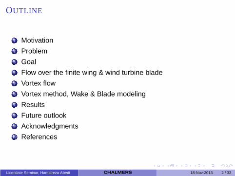
MOTIVATION
Aerodynamic load as the largest loads acting on wind turbineblades.Acquiring an accurate-fast method to predict aerodynamic loads.Preparing input data for the aeroelastic and drive train system.Decreasing the operating and maintenance costs.
Licentiate Seminar, Hamidreza Abedi 18-Nov-2013 3 / 33
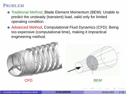
PROBLEM
Traditional Method, Blade Element Momentum (BEM): Unable topredict the unsteady (transient) load, valid only for limitedoperating condition.
Advanced Method, Computational Fluid Dynamics (CFD): Beingtoo expensive (computational time), making it impracticalengineering method.
CFD BEM
Licentiate Seminar, Hamidreza Abedi 18-Nov-2013 4 / 33

GOAL
Preparing an Accurate & Fast design tool to predict unsteadyaerodynamic loads.
Developing Vortex Method instead of BEM and CFD.
Licentiate Seminar, Hamidreza Abedi 18-Nov-2013 5 / 33
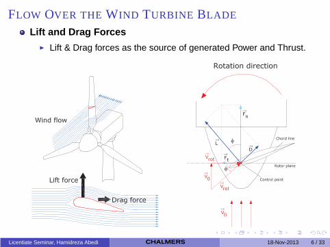
FLOW OVER THE WIND TURBINE BLADE
Lift and Drag Forces◮ Lift & Drag forces as the source of generated Power and Thrust.
Licentiate Seminar, Hamidreza Abedi 18-Nov-2013 6 / 33
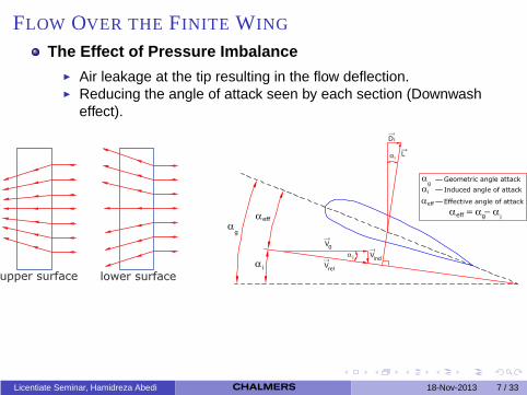
FLOW OVER THE FINITE WING
The Effect of Pressure Imbalance◮ Air leakage at the tip resulting in the flow deflection.◮ Reducing the angle of attack seen by each section (Downwash
effect).
Licentiate Seminar, Hamidreza Abedi 18-Nov-2013 7 / 33
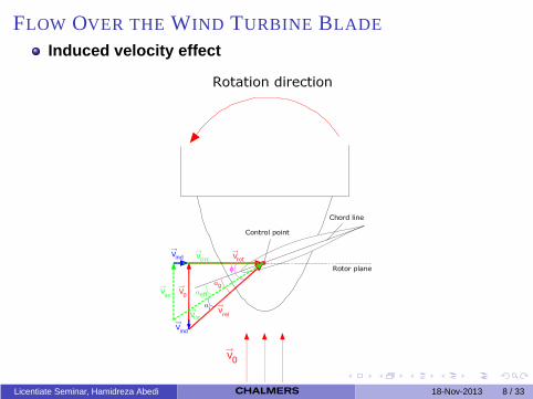
FLOW OVER THE WIND TURBINE BLADE
Induced velocity effect
Licentiate Seminar, Hamidreza Abedi 18-Nov-2013 8 / 33
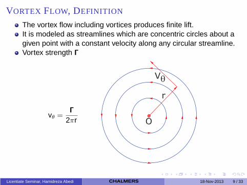
VORTEX FLOW, DEFINITION
The vortex flow including vortices produces finite lift.It is modeled as streamlines which are concentric circles about agiven point with a constant velocity along any circular streamline.Vortex strength Γ
vθ =Γ
2πr
Licentiate Seminar, Hamidreza Abedi 18-Nov-2013 9 / 33
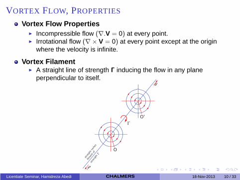
VORTEX FLOW, PROPERTIES
Vortex Flow Properties◮ Incompressible flow (∇.V = 0) at every point.◮ Irrotational flow (∇× V = 0) at every point except at the origin
where the velocity is infinite.
Vortex Filament◮ A straight line of strength Γ inducing the flow in any plane
perpendicular to itself.
Licentiate Seminar, Hamidreza Abedi 18-Nov-2013 10 / 33
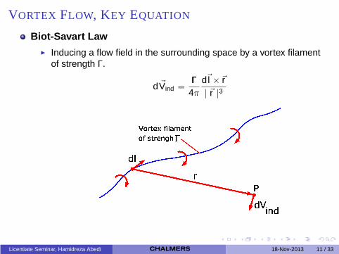
VORTEX FLOW, KEY EQUATION
Biot-Savart Law◮ Inducing a flow field in the surrounding space by a vortex filament
of strength Γ.
d ~Vind =Γ
4π
d~l ×~r| ~r |3
Licentiate Seminar, Hamidreza Abedi 18-Nov-2013 11 / 33
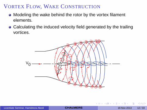
VORTEX FLOW, WAKE CONSTRUCTION
Modeling the wake behind the rotor by the vortex filamentelements.
Calculating the induced velocity field generated by the trailingvortices.
Licentiate Seminar, Hamidreza Abedi 18-Nov-2013 12 / 33
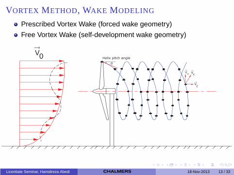
VORTEX METHOD, WAKE MODELING
Prescribed Vortex Wake (forced wake geometry)
Free Vortex Wake (self-development wake geometry)
Licentiate Seminar, Hamidreza Abedi 18-Nov-2013 13 / 33
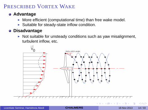
PRESCRIBED VORTEX WAKE
Advantage◮ More efficient (computational time) than free wake model.◮ Suitable for steady-state inflow condition.
Disadvantage◮ Not suitable for unsteady conditions such as yaw misalignment,
turbulent inflow, etc.
Licentiate Seminar, Hamidreza Abedi 18-Nov-2013 14 / 33

FREE VORTEX WAKE
Advantage◮ Applicable for a broad range of wind turbine operating condition
such as yaw condition, atmospheric turbulence, ground boundarylayer effects and etc.
◮ Suitable for unsteady and transient condition.Disadvantage
◮ Computationally expensive than prescribed vortex wake.
Licentiate Seminar, Hamidreza Abedi 18-Nov-2013 15 / 33

FREE VORTEX WAKE, GOVERNING EQUATION
drdt
= V (r, t) r (t = 0) = r0
r, position vector of a Lagrangian markert , timeV, the total velocity field
V = V∞ + Vind ,blade + Vind ,wake
Licentiate Seminar, Hamidreza Abedi 18-Nov-2013 16 / 33

VORTEX METHOD, BLADE MODELING
Lifting line (Replacing the blade with varying strength vortex filament)
Lifting surface (Replacing the blade surface with vortex panels)
Lifting line Lifting surface
Licentiate Seminar, Hamidreza Abedi 18-Nov-2013 17 / 33

DIFFERENT APPROACHES
Lifting Line Prescribed Wake (LLPW)
Vortex Lattice Prescribed Wake (VLPW)
Vortex Lattice Free Wake (VLFW)
LLPW VLPW VLFW
Licentiate Seminar, Hamidreza Abedi 18-Nov-2013 18 / 33
RESULTS
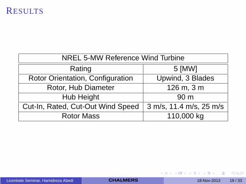
NREL 5-MW Reference Wind Turbine
Rating 5 [MW]Rotor Orientation, Configuration Upwind, 3 Blades
Rotor, Hub Diameter 126 m, 3 mHub Height 90 m
Cut-In, Rated, Cut-Out Wind Speed 3 m/s, 11.4 m/s, 25 m/sRotor Mass 110,000 kg
Licentiate Seminar, Hamidreza Abedi 18-Nov-2013 19 / 33
RESULTS
−10
1 0
2
4−1
0
1
zy
x
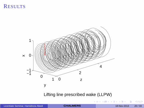
Lifting line prescribed wake (LLPW)
Licentiate Seminar, Hamidreza Abedi 18-Nov-2013 20 / 33

RESULTS
0 2 4 6−1
0
1Tip vortex
z
x
0 2 4 6
0
0.5
1Root vortex
z
x
Lifting line prescribed wake (LLPW)
Licentiate Seminar, Hamidreza Abedi 18-Nov-2013 21 / 33

RESULTS
−10
1 02
46
−1
0
1
z
x
y
Vortex lattice prescribed wake (VLPW)
Licentiate Seminar, Hamidreza Abedi 18-Nov-2013 22 / 33

RESULTS
0 2 4 6−1
0
1Tip vortex
z
y
0 2 4 6
0
0.5
1Root vortex
z
y
Vortex lattice prescribed wake (VLPW)
Licentiate Seminar, Hamidreza Abedi 18-Nov-2013 23 / 33
RESULTS
−1 0 1 02
46
−1
0
1
zx
y
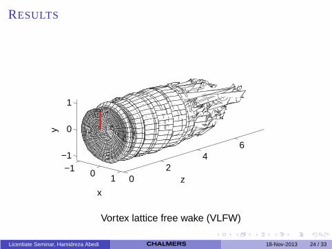
Vortex lattice free wake (VLFW)
Licentiate Seminar, Hamidreza Abedi 18-Nov-2013 24 / 33
RESULTS
0 2 4 6−1
0
1
z
Tip vortex
y
0 2 4 6
−0.50
0.51
z
Root vortex
y
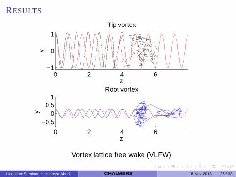
Vortex lattice free wake (VLFW)
Licentiate Seminar, Hamidreza Abedi 18-Nov-2013 25 / 33
RESULTS
0.2 0.4 0.6 0.8 12
4
6
8
10
12
14
16
r/R [−]
AoA
[deg
]
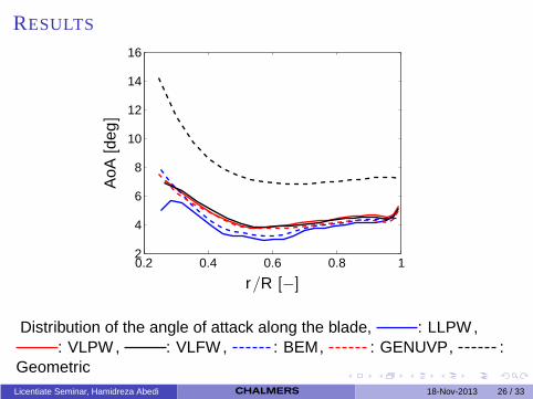
Distribution of the angle of attack along the blade, : LLPW ,: VLPW , : VLFW , : BEM, : GENUVP, :
GeometricLicentiate Seminar, Hamidreza Abedi 18-Nov-2013 26 / 33
RESULTS
0.2 0.4 0.6 0.8 1150
200
250
300
350
400
450
r/R [−]
Ft[N
]
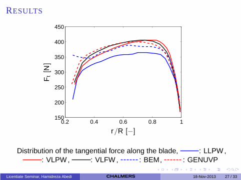
Distribution of the tangential force along the blade, : LLPW ,: VLPW , : VLFW , : BEM, : GENUVP
Licentiate Seminar, Hamidreza Abedi 18-Nov-2013 27 / 33

RESULTS
0.2 0.4 0.6 0.8 10
1000
2000
3000
4000
5000
r/R [−]
Fn
[N/m
]
Distribution of the normal force along the blade, : LLPW , :VLPW , : VLFW , : BEM, : GENUVP
Licentiate Seminar, Hamidreza Abedi 18-Nov-2013 28 / 33
RESULTS
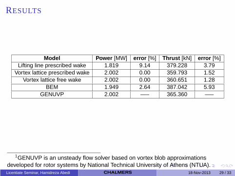
Model Power [MW] error [%] Thrust [kN] error [%]Lifting line prescribed wake 1.819 9.14 379.228 3.79
Vortex lattice prescribed wake 2.002 0.00 359.793 1.52Vortex lattice free wake 2.002 0.00 360.651 1.28
BEM 1.949 2.64 387.042 5.93GENUVP 2.002 —– 365.360 —–
1GENUVP is an unsteady flow solver based on vortex blob approximationsdeveloped for rotor systems by National Technical University of Athens (NTUA).Licentiate Seminar, Hamidreza Abedi 18-Nov-2013 29 / 33
FUTURE OUTLOOK
Developing the free wake code for different operating conditionssuch as turbulent inflow, yaw condition, separated flow and theblade elastic deformation.
Ongoing cooperation with Scandinavian Wind AB through theproject, Hono turbine properties and thrust vector at yawmisalignment.
Coupling the free wake code to the aeroelastic solver calledFreeDyn in cooperation with Teknikgruppen.
Cooperation with the project Fatigue Loads in Forest Regions(TG2-2) through the Swedish Wind Power Technology Centre(SWPTC).
Licentiate Seminar, Hamidreza Abedi 18-Nov-2013 30 / 33

ACKNOWLEDGMENTS
The project TG2-1 is financed through the SWPTC (Swedish WindPower Technology Center) and carried out within the Applied FluidDynamics research group at Chalmers.
The Swedish Wind Power Technology Centre (SWPTC) is a researchcentre for design of wind turbines. The purpose of the Centre is tosupport Swedish industry with knowledge of design techniques as wellas maintenance in the field of wind power. The research in the Centre iscarried out in six theme groups that represent design and operation ofwind turbines; Power and Control Systems, Turbine and Wind loads,Mechanical Power Transmission and System Optimisation, Structureand Foundation, Maintenance and Reliability as well as Cold Climate.This project is part of Theme group 2.
SWPTC’s work is funded by the Swedish Energy Agency, by threeacademic and thirteen industrial partners. The Region Vastra Gotalandalso contributes to the Centre through several collaboration projects.
The technical support of National Technical University of Athens (NTUA)is greatfully acknowledged.
Licentiate Seminar, Hamidreza Abedi 18-Nov-2013 31 / 33
REFERENCES
L.J. Vermeer, J.N. Sørensen, and A. Crespo. Wind Turbine Wake Aerodynamics.Progress in Aerospace Sciences, 39:467-510, 2003
Wilson, R. E. and Lissaman, P. B. S. (1974) Applied Aerodynamics of WindPower Machines, Technical Report NSF-RA-N-74-113, Oregon State University
Anderson, J. D., 2001. Fundamentals of Aerodynamics, 3rd ed. McGraw-Hill
Katz, J., and Allen Plotkin, 2001. Low-Speed Aerodynamics, 2nd ed. CambridgeUniversity Press
Abedi, H., 2011. Aerodynamic Loads On Rotor Blades. Department of AppliedMechanics, Division of Fluid Dynamics, Chalmers University of Technology
Bagai, A., 1995. Contribution to the Mathematical Modeling of Rotor Flow-FieldsUsing a Pseudo-Implicit Free Wake Analysis. University of Maryland,Department of Aerospace Engineering
Jonkman, J., Butterfield, S., Musial, W., and Scott, G., 2009,NREL/TP-500-38060. Definition of a 5-MW reference wind turbine for offshoresystem development. National Renewable Energy Laboratory, Colorado, USA
Voutsinas, S., 2006. Vortex methods in aeronautics: how to make things work.International Journal of Computational Fluid Dynamics, 20, pp. 3-18
Licentiate Seminar, Hamidreza Abedi 18-Nov-2013 32 / 33
Thanks for your attention
Varldens Starkaste Bjorn (”The World’s Strongest Bear”)
Licentiate Seminar, Hamidreza Abedi 18-Nov-2013 33 / 33