TG-16/PC-E COMPONENT VIDEO MOD INSTALL GUIDE · tg-16/pc-e component video mod install guide design...
13
TG-16/PC-E COMPONENT VIDEO MOD INSTALL GUIDE DESIGN BY THESTEVE PCB BUILT & ASSEMBLED BY TURBOKON SPECIAL THANKS: BLUEBMW THEOLDMAN NIGHTWOLVE WWW.TG16PCEMODS.COM Converts RGB & Sync to YPbPr Only works on HDTV sets that support 240P resolution
Transcript of TG-16/PC-E COMPONENT VIDEO MOD INSTALL GUIDE · tg-16/pc-e component video mod install guide design...

TG-16/PC-E COMPONENT VIDEOMOD INSTALL GUIDE
DESIGN BY THESTEVE
PCB BUILT & ASSEMBLED BY TURBOKON
SPECIAL THANKS:
BLUEBMW
THEOLDMAN
NIGHTWOLVE
WWW.TG16PCEMODS.COM
Converts RGB & Sync to YPbPr
Only works on HDTV sets that support 240P resolution

HOW TO TEST YOU HDTV SET FOR 240P SUPPORTS
• Using a classic system that has composite video output, plug the yellow rcaplug to the “Y” input of your HDTV’s component video. If you get picture withno colors then your HDTV supports 240P via component video.

PARTS & TOOLS LIST
• 28awg or 26awg multi-strand wires (recommended)
(32awg wrapping wires from radio shack will work)
• Wire stripper & clipper
• Solder
• Plier
• Exactor knife
• Electric tape
• Two sided hanging tape
• 4.5mm security bit (torx t-10 for pce duo)
• Mini flat & Philip head screw driver
• Hot glue gun

TAPPING THE RGB & SYNC
• RGB & Sync can be tapped from Hu6260 chip or expansion bus.
• It is highly recommended to tap RGB & Sync from expansion bus if you can tominimize damage to Hu6260 legs.
Hu6260 Expansion bus
• Red = Pin 49 Pin 23A
• Green = Pin 47 Pin 23B
• Blue = Pin 51 Pin 23C
• Sync = Pin 44 Pin 22C

OPENING THE CONSOLE
I cannot be held responsible for any damages that may occur while attemptingthis mod. Proceed at you own risk!!!!!
• Remove all the screws located on the bottom of the console with theapproximate security bit.
• Remove the shield and locate the Hu6260. On the duo, the Hu chip sets arelocated on the other side of the mother board so it is necessary to remove theMB by removing a few screws and undoing a few connections.
TAPPING THE RGB & SYNC
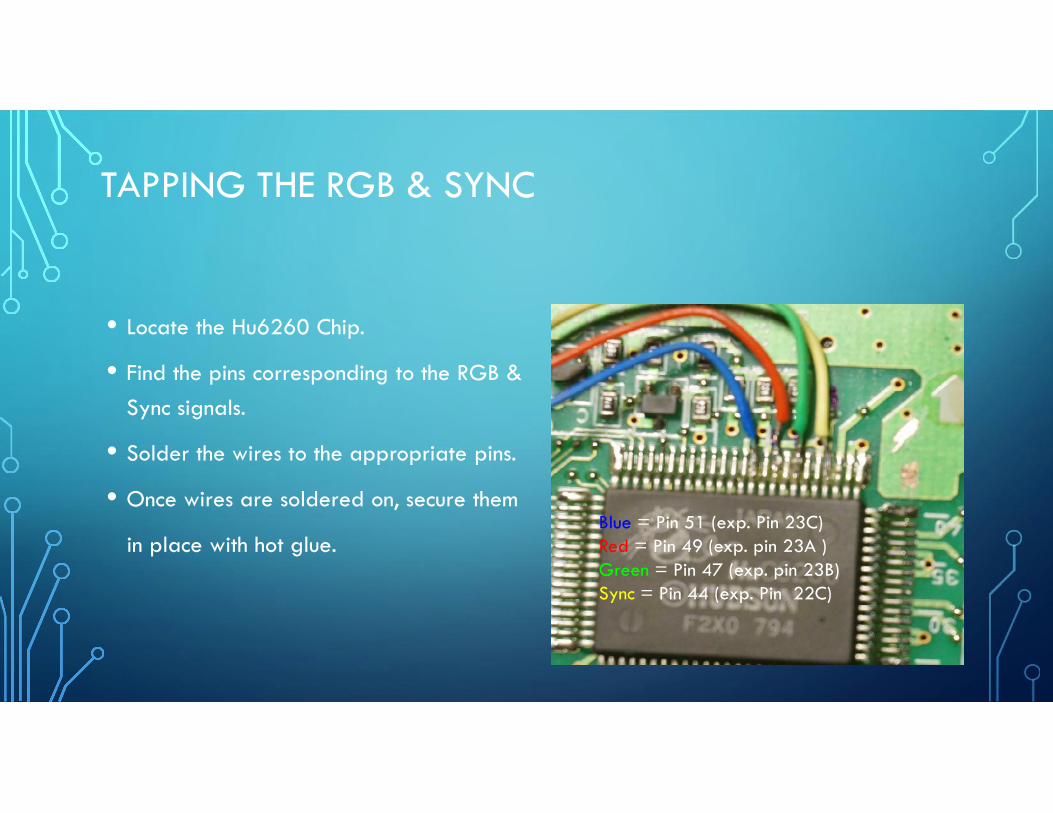
• Locate the Hu6260 Chip.
• Find the pins corresponding to the RGB &Sync signals.
• Solder the wires to the appropriate pins.
• Once wires are soldered on, secure them
in place with hot glue.Blue = Pin 51 (exp. Pin 23C)Red = Pin 49 (exp. pin 23A )Green = Pin 47 (exp. pin 23B)Sync = Pin 44 (exp. Pin 22C)

JAIL BARS FIXED
• Jail bars will appear on screen when RGB are utilized.
• Two 22uf caps are needed to help reduce theappearance of Jail bars. In my experience, the jail barsfix seems to work best on a duo.
• One end of each smt caps are soldered to Pin 41 & 43of the Hu6260 with the other ends to ground. For theduo, ground is nearby to pin 41 & 43. With an exactorknife, scrape top green layer until the copper is bare.
• Position the caps and solder into place
• Polarized caps can be also use, notice the polarity ifpolarized caps are to be used. +
+ -
-
Pin 43
Pin 41

INSTALLING THE COMPONENT MOD BOARD
• Locate a good spot forthe component modboard. On the turbo duo,I mounted the board usingthe two sided tape on theshield. There are severalplaces to get ground and5V, I got ground fromshield and 5v from Pin 38of hucard pins.

• On the turbografx, I mounted the board near the expansion bus.
• On the turbo express, I mounted the board on the front shield.
INSTALLING THE COMPONENT MOD BOARD

INSTALLING THE COMPONENT MOD BOARD
• The component mod board can also be installed in the TG16 Dock or the IFUusing the corresponding pins to the expansion port.

• Solder the appropriateinput wires fromHu6260 or ExpansionBus wires to the RGB &SYNC side of the chip.
• Solder the appropriatewires on the output sideof the chip to desiredconnection type.
INSTALLING THE COMPONENT MOD BOARD

CHOOSE OUTPUT METHODSVia RCA jacks Via mini Din-7 Via Din-8

TRIM POTS• It comes preset but adjustment to the colors & brightness levels may be
needed for individual systems and TV sets.
• With a mini flat screw driver, adjust pots at R6 for red level, pots atR4 for blue level and pots at R17 for brightness level.
Adjustbrightness &impedanceout to TV set
Adjust redlevel
Adjust bluelevel


![INSTALL GUIDE DIR-GM(RS)-GM7-[FLRSGM7]-EN...Dec 06, 2019 · make model year install type features data immobilizer bypass 3x lock start/standalone mod. priority unlock door lock](https://static.fdocuments.in/doc/165x107/60aca68dc3ed9406e4032cb3/install-guide-dir-gmrs-gm7-flrsgm7-en-dec-06-2019-make-model-year-install.jpg)