
Texas Instruments Registration Identification … July 1996 Micro-reader Module 1. Introduction 1.1...
28
Texas Instruments Registration and Identification System Micro-reader RI-STU-MRD1 Reference Manual 11-06-21-027 25-July-1996
Transcript of Texas Instruments Registration Identification … July 1996 Micro-reader Module 1. Introduction 1.1...
Texas InstrumentsRegistration
andIdentification
System
Micro-reader
RI-STU-MRD1
Reference Manual
11-06-21-027 25-July-1996
Micro-reader Module 25 July 1996
Edition Notice: Second Edition - July 1996
This is the second edition of this manual, it describes the following equipment:
TIRIS Micro-reader Module RI-STU-MRD1
Texas Instruments reserves the right to change its products or services at any time withoutnotice. TI provides customer assistance in various technical areas, but does not have full
access to data concerning the uses and applications of customer's products. Therefore TIassumes no responsibility for customer product design or for infringement of patents and/orthe rights of third parties, which may result from assistance provided by TI.
CE-Declaration
The Micro-reader module complies with the European CE requirements as specified in the EMCDirective 89/336/EEC. For details please refer to Appendix C of this manual.
The TIRIS logo and the word TIRIS are registered trademarks of Texas Instruments Incorporated.
Copyright 1996 Texas Instruments Incorporated.
All rights reserved.
25 July 1996 Micro-reader Module
Contents
1. Introduction ...........................................................................................................................................................51.1 General .............................................................................................................................................................51.2 Product Description ..........................................................................................................................................51.3 Product Option Coding .....................................................................................................................................51.4 Conventions ......................................................................................................................................................5
2. Product Function ....................................................................................................................................................72.1 Description .......................................................................................................................................................7
2.1.1 Power Supply ............................................................................................................................................72.1.2 Antenna ....................................................................................................................................................72.1.3 Synchronization ........................................................................................................................................82.1.4 Trigger Mode ............................................................................................................................................82.1.5 Continuous Mode ......................................................................................................................................82.1.6 Serial Communication ...............................................................................................................................9
2.2 Connector Pins .................................................................................................................................................9
3. Communications Protocol ....................................................................................................................................133.1 Protocol PC to Micro-reader ...........................................................................................................................13
3.1.1 Start Mark ...............................................................................................................................................133.1.2 Length .....................................................................................................................................................133.1.3 Command Field .......................................................................................................................................143.1.4 Data Field ...............................................................................................................................................153.1.5 BCC ........................................................................................................................................................15
3.2 Protocol Micro-reader to PC ...........................................................................................................................163.2.1 Start Mark ...............................................................................................................................................163.2.2 Length .....................................................................................................................................................163.2.3 Status ......................................................................................................................................................163.2.4 Data Field ...............................................................................................................................................17
3.2.5 BCC ............................................................................................................................................................17
4. Specifications .......................................................................................................................................................184.1 Absolute Maximum Ratings ............................................................................................................................184.2 Recommended Operating Conditions ..............................................................................................................194.3 Timings ..........................................................................................................................................................194.4 Mechanical Data .............................................................................................................................................20
5. Transponder Protocols .........................................................................................................................................215.1 Transponder commands ..................................................................................................................................21
5.1.1 Read RO, R/W .........................................................................................................................................215.1.2 Program R/W ..........................................................................................................................................215.1.3 Addressing MPTs/SAMPTs .....................................................................................................................22
5.1.3.1 General Read Page of MPT/SAMPT .................................................................................................225.1.3.2 Program Page of MPT/SAMPT ........................................................................................................225.1.3.3 Lock Page of MPT/SAMPT ..............................................................................................................225.1.3.4 Selective Read Page of SAMPT ........................................................................................................235.1.3.5 Selective Program Page of SAMPT ..................................................................................................235.1.3.6 Selective Lock Page of SAMPT ........................................................................................................23
5.2 Transponder Responses ..................................................................................................................................235.2.1 Read Only Transponder ...........................................................................................................................235.2.2 Read/Write Transponder .........................................................................................................................245.2.3 MPT/SAMPT...........................................................................................................................................24
6. Communication Protocol Examples .....................................................................................................................256.1 PC to Micro-reader .........................................................................................................................................256.2 Micro-reader to PC .........................................................................................................................................26
Appendix A: Abbreviations .......................................................................................................................................27
Appendix B: Signal Names .......................................................................................................................................28
Appendix C: CE Declaration ....................................................................................................................................28
Micro-reader Module 25 July 1996
Figures
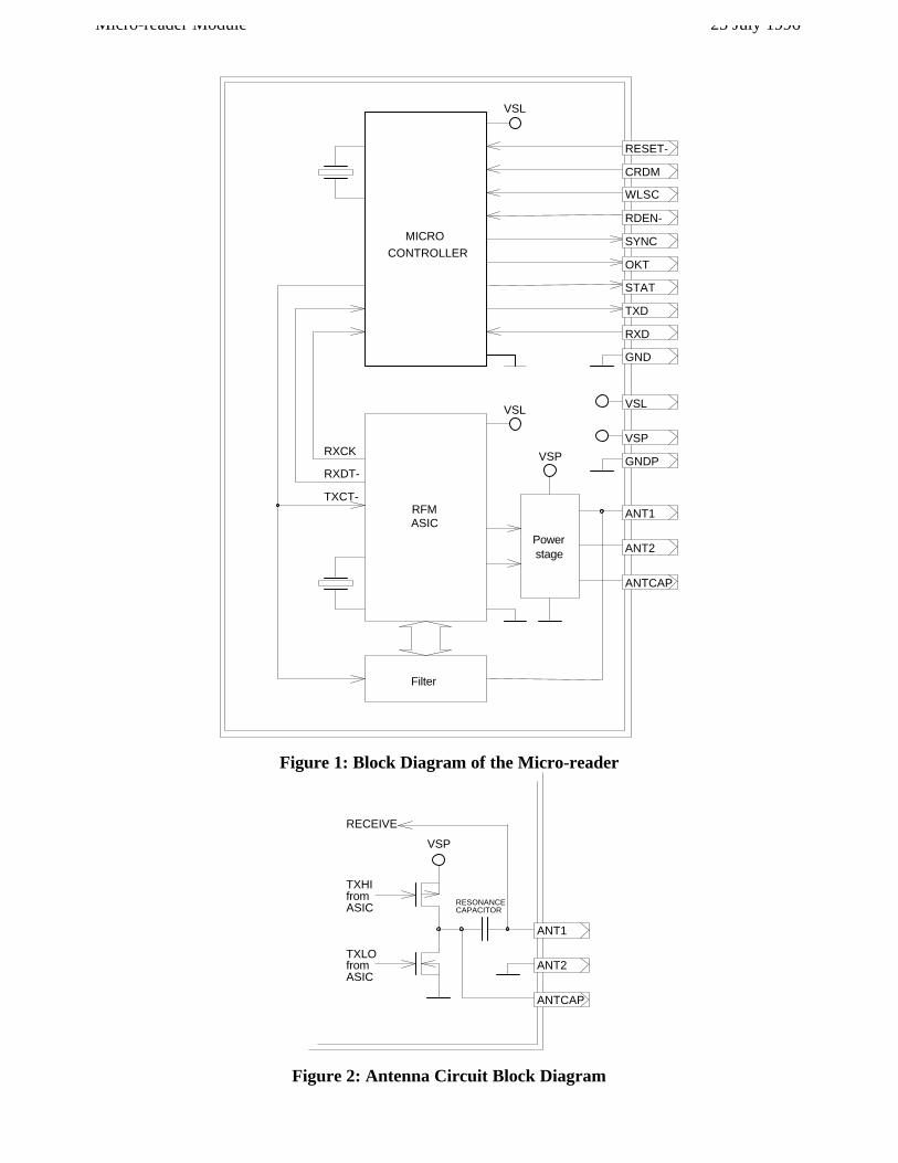
Figure 1: Block Diagram of the Micro-reader ..............................................................................................................6
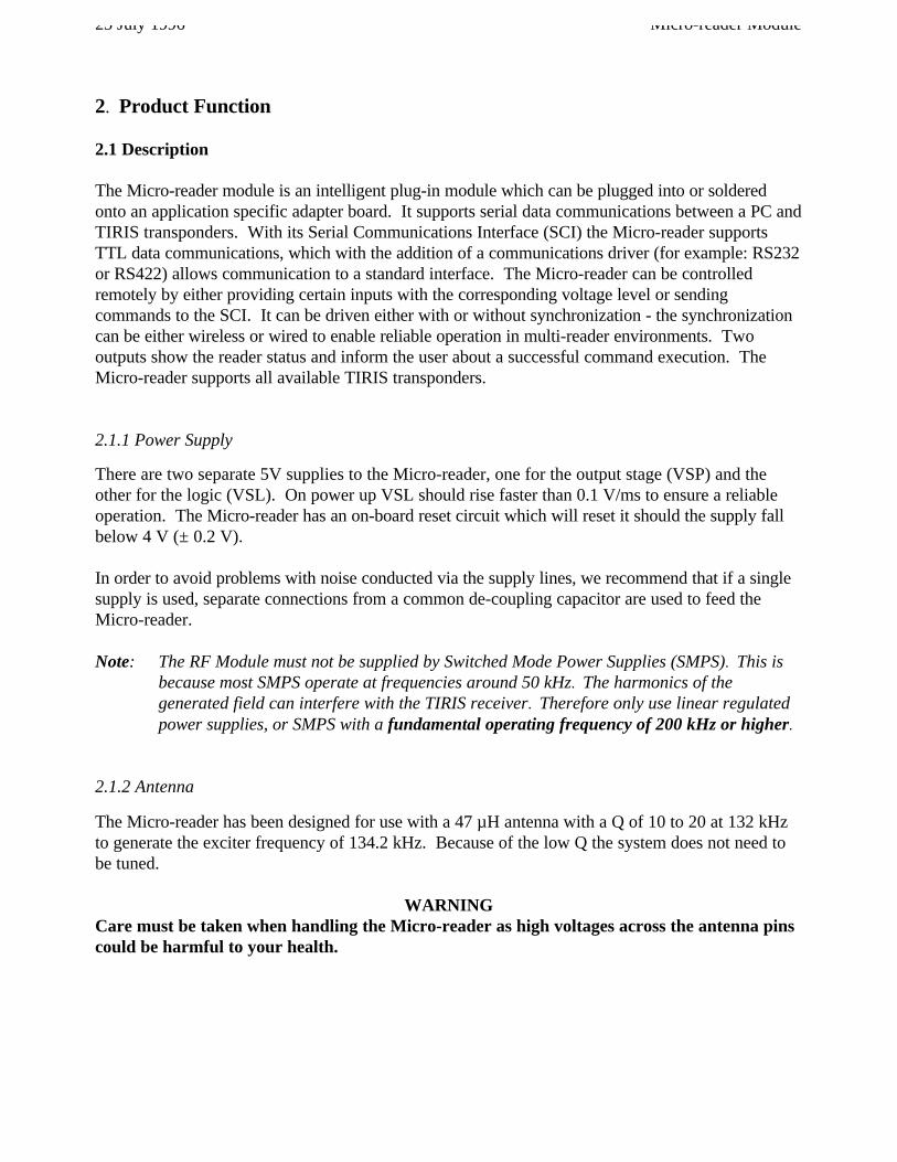
Figure 2: Antenna Circuit Block Diagram ...................................................................................................................6
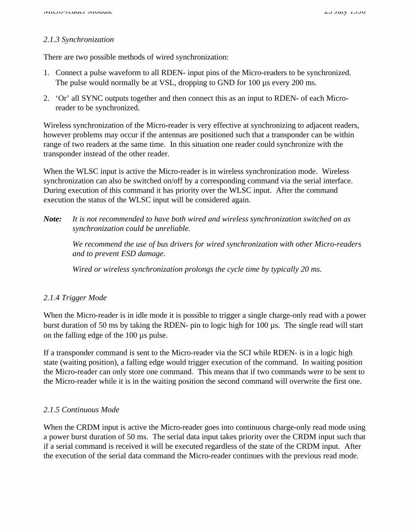
Figure 3: Micro-reader Pin Connections .....................................................................................................................9
Figure 4: Top, Front and Side View (measurements in mm) .....................................................................................20
Figure 5: Read function ............................................................................................................................................21
Figure 6: Programming data format of the 64-bit Read/Write Transponder ...............................................................21
Figure 7: Data Format of the General Read Page Function ........................................................................................22
Figure 8: Programming Data Format of the MPT ......................................................................................................22
Figure 9: Lock Page Data Format of the MPT/SAMPT .............................................................................................22
Figure 10: Data Format of the Selective Read Page Function ....................................................................................23
Figure 11: Data Format of the Selective Program Page Function ...............................................................................23
Figure 12: Data format of the Selective Lock Page function ......................................................................................23
Figure 13: RO Read Data Format ..............................................................................................................................23
Figure 14: R/W Read Data Format ............................................................................................................................24
Figure 15: MPT/SAMPT Read Data Format .............................................................................................................24
Tables
Table 1: Pin Connections ..........................................................................................................................................10

25 July 1996 Micro-reader Module
1. Introduction
1.1 General
This document provides information about the TIRIS Micro-reader Module RI-STU-MRD1.It describes the module and how to integrate it.
1.2 Product Description
The Micro-reader is an intelligent module providing RF and Control functions to read and programTIRIS transponders. It is equipped with a Serial Communications Interface (SCI) which may bedirectly connected to commonly used system controllers. The Micro-reader works together with a47 µHenry, low-Q antenna, and therefore the system does not need tuning.
1.3 Product Option Coding
For product and ordering numbers of TIRIS Products and Accessories, please contact your localTIRIS Application Center.
There is only one version of the Micro-reader Module, that is: RI-STU-MRD1
1.4 Conventions
Certain conventions are used in this document in order to display important information, theseconventions are:
WARNINGA warning is used where care must be taken, or a certain proceduremust be followed, in order to prevent injury or harm to your health.
CAUTION: This indicates information on conditions which must be met, or a procedurewhich must be followed, which if not heeded could cause permanent damage tothe Module.
Note: Indicates conditions which must be met, or procedures which must be followed, to ensureproper functioning of the Module.
HINT: Indicates information which makes usage of the Module easier.
Micro-reader Module 25 July 1996
RESET-
CRDM
RDEN-
SYNC
OKT
STAT
TXD
RXD
GND
VSL
GNDP
MICRO
CONTROLLER
RFMASIC
ANT1
ANT2
ANTCAP
Powerstage
Filter
RXCK
RXDT-
TXCT-
VSL
VSP
VSL
WLSC
VSP
Figure 1: Block Diagram of the Micro-reader
ANT1
ANT2
ANTCAP
TXHIfromASIC
TXLOfromASIC
VSP
RECEIVE
RESONANCECAPACITOR
Figure 2: Antenna Circuit Block Diagram
25 July 1996 Micro-reader Module
2. Product Function
2.1 Description
The Micro-reader module is an intelligent plug-in module which can be plugged into or solderedonto an application specific adapter board. It supports serial data communications between a PC andTIRIS transponders. With its Serial Communications Interface (SCI) the Micro-reader supportsTTL data communications, which with the addition of a communications driver (for example: RS232or RS422) allows communication to a standard interface. The Micro-reader can be controlledremotely by either providing certain inputs with the corresponding voltage level or sendingcommands to the SCI. It can be driven either with or without synchronization - the synchronizationcan be either wireless or wired to enable reliable operation in multi-reader environments. Twooutputs show the reader status and inform the user about a successful command execution. TheMicro-reader supports all available TIRIS transponders.
2.1.1 Power Supply
There are two separate 5V supplies to the Micro-reader, one for the output stage (VSP) and theother for the logic (VSL). On power up VSL should rise faster than 0.1 V/ms to ensure a reliableoperation. The Micro-reader has an on-board reset circuit which will reset it should the supply fallbelow 4 V (± 0.2 V).
In order to avoid problems with noise conducted via the supply lines, we recommend that if a singlesupply is used, separate connections from a common de-coupling capacitor are used to feed theMicro-reader.
Note: The RF Module must not be supplied by Switched Mode Power Supplies (SMPS). This isbecause most SMPS operate at frequencies around 50 kHz. The harmonics of thegenerated field can interfere with the TIRIS receiver. Therefore only use linear regulatedpower supplies, or SMPS with a fundamental operating frequency of 200 kHz or higher.
2.1.2 Antenna
The Micro-reader has been designed for use with a 47 µH antenna with a Q of 10 to 20 at 132 kHzto generate the exciter frequency of 134.2 kHz. Because of the low Q the system does not need tobe tuned.
WARNINGCare must be taken when handling the Micro-reader as high voltages across the antenna pinscould be harmful to your health.
Micro-reader Module 25 July 1996
2.1.3 Synchronization
There are two possible methods of wired synchronization:
1. Connect a pulse waveform to all RDEN- input pins of the Micro-readers to be synchronized.The pulse would normally be at VSL, dropping to GND for 100 µs every 200 ms.
2. ‘Or’ all SYNC outputs together and then connect this as an input to RDEN- of each Micro-reader to be synchronized.
Wireless synchronization of the Micro-reader is very effective at synchronizing to adjacent readers,however problems may occur if the antennas are positioned such that a transponder can be withinrange of two readers at the same time. In this situation one reader could synchronize with thetransponder instead of the other reader.
When the WLSC input is active the Micro-reader is in wireless synchronization mode. Wirelesssynchronization can also be switched on/off by a corresponding command via the serial interface.During execution of this command it has priority over the WLSC input. After the commandexecution the status of the WLSC input will be considered again.
Note: It is not recommended to have both wired and wireless synchronization switched on assynchronization could be unreliable.
We recommend the use of bus drivers for wired synchronization with other Micro-readersand to prevent ESD damage.
Wired or wireless synchronization prolongs the cycle time by typically 20 ms.
2.1.4 Trigger Mode
When the Micro-reader is in idle mode it is possible to trigger a single charge-only read with a powerburst duration of 50 ms by taking the RDEN- pin to logic high for 100 µs. The single read will starton the falling edge of the 100 µs pulse.
If a transponder command is sent to the Micro-reader via the SCI while RDEN- is in a logic highstate (waiting position), a falling edge would trigger execution of the command. In waiting positionthe Micro-reader can only store one command. This means that if two commands were to be sent tothe Micro-reader while it is in the waiting position the second command will overwrite the first one.
2.1.5 Continuous Mode
When the CRDM input is active the Micro-reader goes into continuous charge-only read mode usinga power burst duration of 50 ms. The serial data input takes priority over the CRDM input such thatif a serial command is received it will be executed regardless of the state of the CRDM input. Afterthe execution of the serial data command the Micro-reader continues with the previous read mode.
25 July 1996 Micro-reader Module
In the default continuous read mode, only those valid RO, R/W or MPT IDs that differ from thepreviously read ID; or valid IDs read after a “NO READ”, are transferred via the SCI (NormalMode). The Micro-reader can be set to transfer all valid IDs that are read (Line Mode) by means of acorresponding serial data command.
Without synchronization the Micro-reader has a reading frequency of approximately 10 readouts persecond using a power burst duration of 50 ms.
2.1.6 Serial Communication
The two serial I/O pins are configured for 9600 Baud, 1 start bit, 8 data bits, no parity and 1 stop bit;they can be connected directly to a communications driver to allow a half duplex communicationwith a PC via its serial communications interface (for example: RS232 or RS422).
The communications protocol is specified in Section 3.
Handshake
The Micro-reader accepts handshake commands Xon/Xoff. When it receives an Xoff (13hex) theMicro-reader stops its current operation and stops transmitting data via the serial port. It stays inidle mode until Xon (11hex) is received when it continues with the previous mode/command. Duringthis idle period the Micro-reader accepts commands via the serial port , however, it waits for itsexecution until Xon is received. In this idle period the Micro-reader can store only one command.
Note: While receiving a command protocol from the serial port Xon/Xoff is interpreted asnormal data without affecting the serial communication.
2.2 Connector Pins
The Micro-reader module has 30 pin connections which are shown in figure 3 and listed in table 1.
Figure 3: Micro-reader Pin Connections
Micro-reader Module 25 July 1996
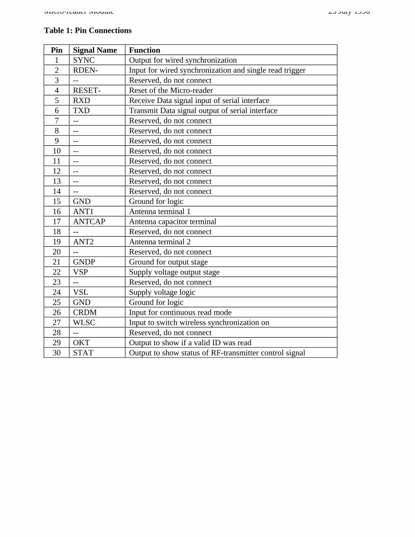
Table 1: Pin Connections
Pin Signal Name Function1 SYNC Output for wired synchronization2 RDEN- Input for wired synchronization and single read trigger3 -- Reserved, do not connect4 RESET- Reset of the Micro-reader5 RXD Receive Data signal input of serial interface6 TXD Transmit Data signal output of serial interface7 -- Reserved, do not connect8 -- Reserved, do not connect9 -- Reserved, do not connect
10 -- Reserved, do not connect11 -- Reserved, do not connect12 -- Reserved, do not connect13 -- Reserved, do not connect14 -- Reserved, do not connect15 GND Ground for logic16 ANT1 Antenna terminal 117 ANTCAP Antenna capacitor terminal18 -- Reserved, do not connect19 ANT2 Antenna terminal 220 -- Reserved, do not connect21 GNDP Ground for output stage22 VSP Supply voltage output stage23 -- Reserved, do not connect24 VSL Supply voltage logic25 GND Ground for logic26 CRDM Input for continuous read mode27 WLSC Input to switch wireless synchronization on28 -- Reserved, do not connect29 OKT Output to show if a valid ID was read30 STAT Output to show status of RF-transmitter control signal
25 July 1996 Micro-reader Module
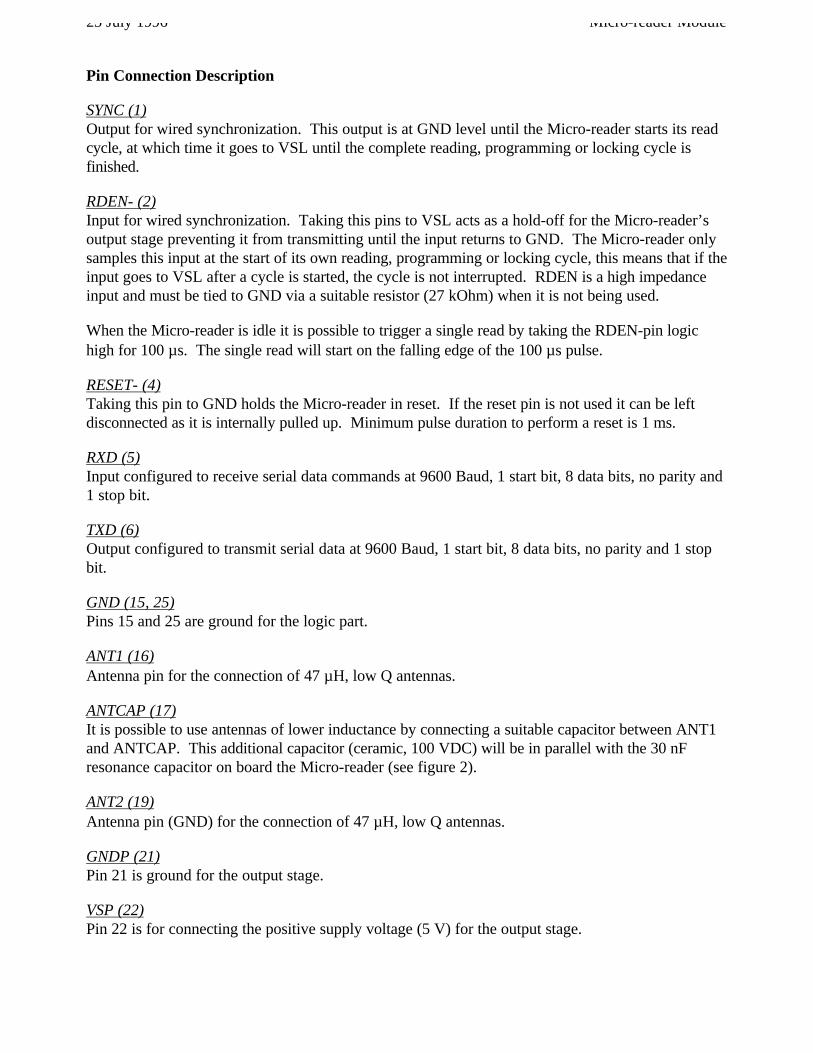
Pin Connection Description
SYNC (1)Output for wired synchronization. This output is at GND level until the Micro-reader starts its readcycle, at which time it goes to VSL until the complete reading, programming or locking cycle isfinished.
RDEN- (2)Input for wired synchronization. Taking this pins to VSL acts as a hold-off for the Micro-reader’soutput stage preventing it from transmitting until the input returns to GND. The Micro-reader onlysamples this input at the start of its own reading, programming or locking cycle, this means that if theinput goes to VSL after a cycle is started, the cycle is not interrupted. RDEN is a high impedanceinput and must be tied to GND via a suitable resistor (27 kOhm) when it is not being used.
When the Micro-reader is idle it is possible to trigger a single read by taking the RDEN-pin logichigh for 100 µs. The single read will start on the falling edge of the 100 µs pulse.
RESET- (4)Taking this pin to GND holds the Micro-reader in reset. If the reset pin is not used it can be leftdisconnected as it is internally pulled up. Minimum pulse duration to perform a reset is 1 ms.
RXD (5)Input configured to receive serial data commands at 9600 Baud, 1 start bit, 8 data bits, no parity and1 stop bit.
TXD (6)Output configured to transmit serial data at 9600 Baud, 1 start bit, 8 data bits, no parity and 1 stopbit.
GND (15, 25)Pins 15 and 25 are ground for the logic part.
ANT1 (16)Antenna pin for the connection of 47 µH, low Q antennas.
ANTCAP (17)It is possible to use antennas of lower inductance by connecting a suitable capacitor between ANT1and ANTCAP. This additional capacitor (ceramic, 100 VDC) will be in parallel with the 30 nFresonance capacitor on board the Micro-reader (see figure 2).
ANT2 (19)Antenna pin (GND) for the connection of 47 µH, low Q antennas.
GNDP (21)Pin 21 is ground for the output stage.
VSP (22)Pin 22 is for connecting the positive supply voltage (5 V) for the output stage.
Micro-reader Module 25 July 1996
VSL (24)Pin 24 is for connecting the positive supply voltage (5 V) for the logic part.
CRDM (26)Supplying pin 26 with a logic high signal causes the Micro-reader to run in a continuous charge-onlyread mode (see Section 2.1.5 for more information).
When the CRDM pin is tied to logic low, the Micro-reader is in an idle state waiting for commandsvia the serial interface or for a trigger signal (RDEN-) to start a single read out cycle. CRDM is ahigh impedance input and must be tied to either VSL or GND via a suitable resistor (27 kOhm).
WLSC (27)Pin 27 enables or disables wireless synchronization. To enable the wireless synchronization, pin 27must be taken to VSL. When wireless synchronization is enabled, the Micro-reader will try tosynchronize its transmit signals with any other readers in range. To disable wireless synchronizationpin 27 must be taken to GND. Pin 27 is a high impedance input and must be tied to either VSL orGND via a suitable resistor (27 kOhm).
Wireless synchronization can also be switched on/off by a corresponding command via the serialinterface. During execution of this command it has priority over the WLSC input.
OKT (29)This output is set to logic high for approx. 60 ms if a valid transponder was read. It can beconnected to an LED externally to indicate the result of the read cycle.
STAT(30)Pin 30 is set to logic low when the RF-transmitter is activated. Supplying an external LED with thissignal makes the status of the Micro-reader visible.
25 July 1996 Micro-reader Module
3. Communications Protocol
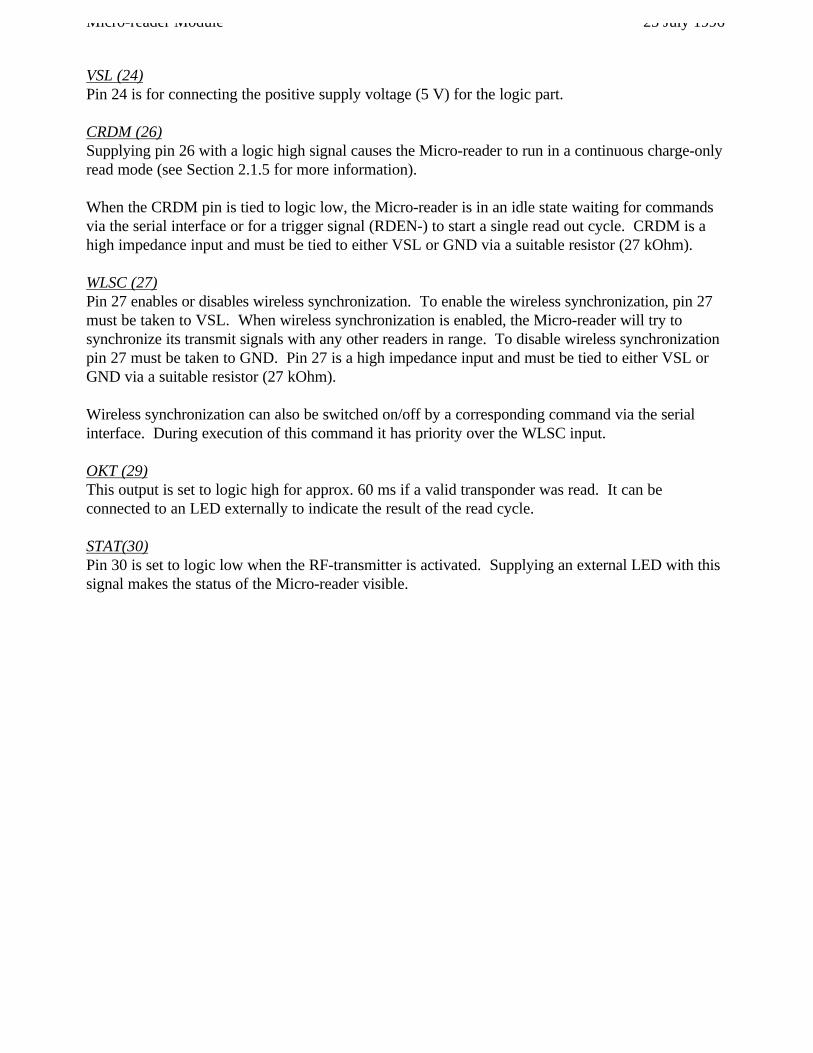
3.1 Protocol PC to Micro-reader
Start Length BCCCmd 1 Cmd 2 Data
Byte Contents (hexadecimal value)0 Start Mark (SOH, 01hex)1 Length2 Command Field (1)3 Command Field (2) (optional)
4(3) Data Field (1)..
N+3(2) Data Field (N)N+4(3) BCC
Note: The total number of bytes sent within a protocol frame (including Start Mark and BCC) is limited to 41 bytes.
Examples are given in Section 6.1.
3.1.1 Start Mark
The ‘Start-Mark’ signifies the beginning of a message. It is represented by the ASCII character SOH(Start Of Header, 01hex).
3.1.2 Length
The ‘Length’ byte indicates the length, in bytes, of the following Command and Data Fields.
Micro-reader Module 25 July 1996
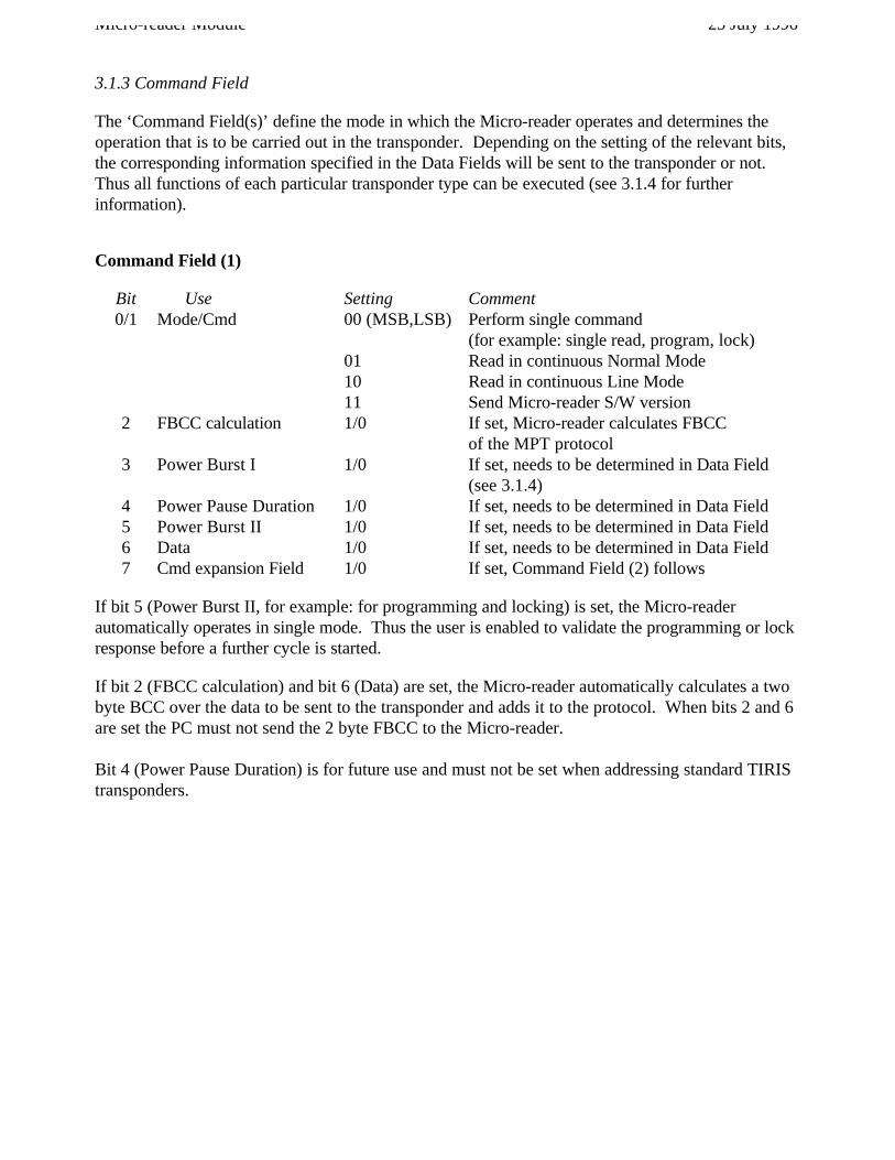
3.1.3 Command Field
The ‘Command Field(s)’ define the mode in which the Micro-reader operates and determines theoperation that is to be carried out in the transponder. Depending on the setting of the relevant bits,the corresponding information specified in the Data Fields will be sent to the transponder or not.Thus all functions of each particular transponder type can be executed (see 3.1.4 for furtherinformation).
Command Field (1)
Bit Use Setting Comment0/1 Mode/Cmd 00 (MSB,LSB) Perform single command
(for example: single read, program, lock)01 Read in continuous Normal Mode10 Read in continuous Line Mode11 Send Micro-reader S/W version
2 FBCC calculation 1/0 If set, Micro-reader calculates FBCCof the MPT protocol
3 Power Burst I 1/0 If set, needs to be determined in Data Field (see 3.1.4)
4 Power Pause Duration 1/0 If set, needs to be determined in Data Field5 Power Burst II 1/0 If set, needs to be determined in Data Field6 Data 1/0 If set, needs to be determined in Data Field7 Cmd expansion Field 1/0 If set, Command Field (2) follows
If bit 5 (Power Burst II, for example: for programming and locking) is set, the Micro-readerautomatically operates in single mode. Thus the user is enabled to validate the programming or lockresponse before a further cycle is started.
If bit 2 (FBCC calculation) and bit 6 (Data) are set, the Micro-reader automatically calculates a twobyte BCC over the data to be sent to the transponder and adds it to the protocol. When bits 2 and 6are set the PC must not send the 2 byte FBCC to the Micro-reader.
Bit 4 (Power Pause Duration) is for future use and must not be set when addressing standard TIRIStransponders.
25 July 1996 Micro-reader Module
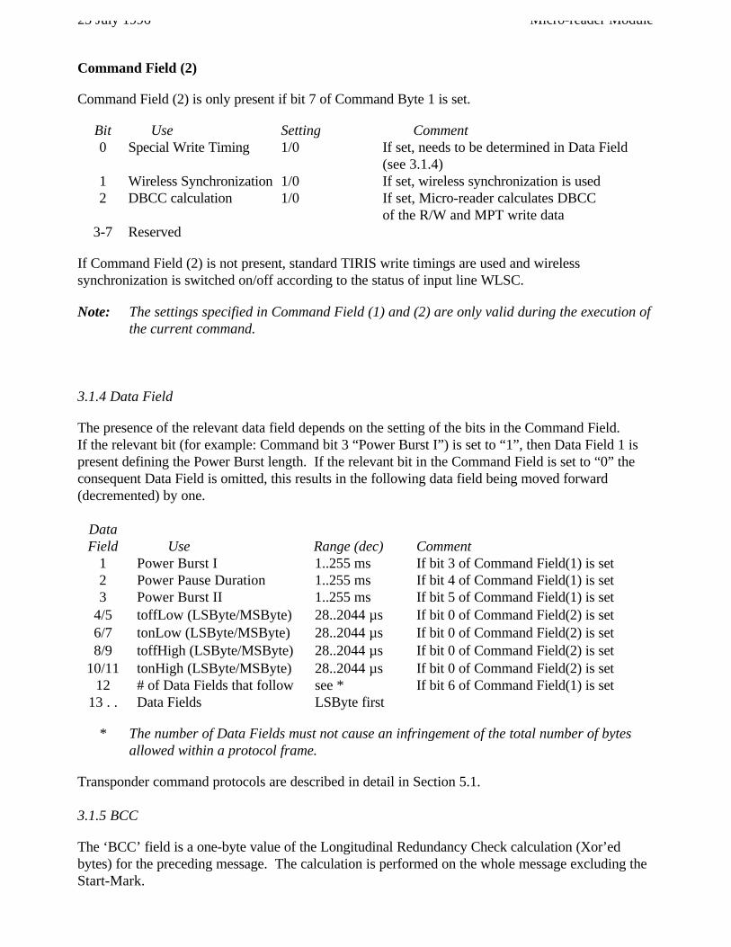
Command Field (2)
Command Field (2) is only present if bit 7 of Command Byte 1 is set.
Bit Use Setting Comment0 Special Write Timing 1/0 If set, needs to be determined in Data Field
(see 3.1.4)1 Wireless Synchronization 1/0 If set, wireless synchronization is used2 DBCC calculation 1/0 If set, Micro-reader calculates DBCC
of the R/W and MPT write data3-7 Reserved
If Command Field (2) is not present, standard TIRIS write timings are used and wirelesssynchronization is switched on/off according to the status of input line WLSC.
Note: The settings specified in Command Field (1) and (2) are only valid during the execution ofthe current command.
3.1.4 Data Field
The presence of the relevant data field depends on the setting of the bits in the Command Field.If the relevant bit (for example: Command bit 3 “Power Burst I”) is set to “1”, then Data Field 1 ispresent defining the Power Burst length. If the relevant bit in the Command Field is set to “0” theconsequent Data Field is omitted, this results in the following data field being moved forward(decremented) by one.
DataField Use Range (dec) Comment
1 Power Burst I 1..255 ms If bit 3 of Command Field(1) is set2 Power Pause Duration 1..255 ms If bit 4 of Command Field(1) is set3 Power Burst II 1..255 ms If bit 5 of Command Field(1) is set
4/5 toffLow (LSByte/MSByte) 28..2044 µs If bit 0 of Command Field(2) is set6/7 tonLow (LSByte/MSByte) 28..2044 µs If bit 0 of Command Field(2) is set8/9 toffHigh (LSByte/MSByte) 28..2044 µs If bit 0 of Command Field(2) is set
10/11 tonHigh (LSByte/MSByte) 28..2044 µs If bit 0 of Command Field(2) is set12 # of Data Fields that follow see * If bit 6 of Command Field(1) is set
13 . . Data Fields LSByte first
* The number of Data Fields must not cause an infringement of the total number of bytesallowed within a protocol frame.
Transponder command protocols are described in detail in Section 5.1.
3.1.5 BCC
The ‘BCC’ field is a one-byte value of the Longitudinal Redundancy Check calculation (Xor’edbytes) for the preceding message. The calculation is performed on the whole message excluding theStart-Mark.
Micro-reader Module 25 July 1996
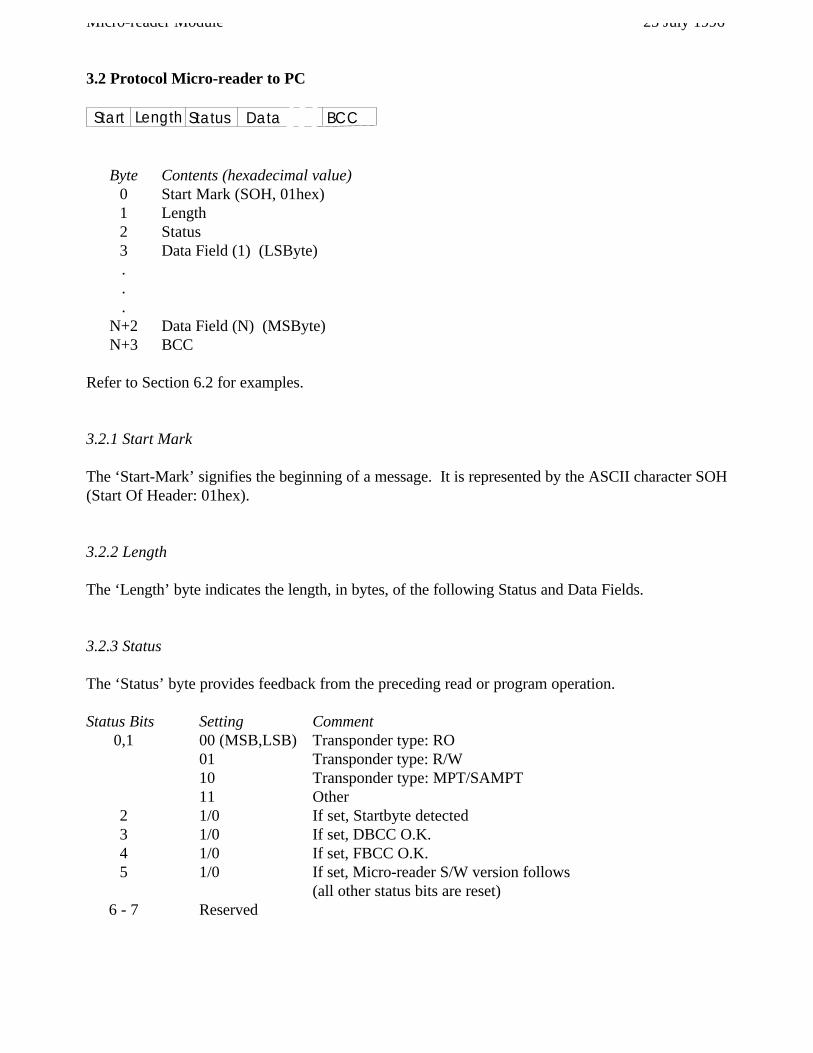
3.2 Protocol Micro-reader to PC
Start Length BCCStatus Data
Byte Contents (hexadecimal value)0 Start Mark (SOH, 01hex)1 Length2 Status3 Data Field (1) (LSByte)...
N+2 Data Field (N) (MSByte)N+3 BCC
Refer to Section 6.2 for examples.
3.2.1 Start Mark
The ‘Start-Mark’ signifies the beginning of a message. It is represented by the ASCII character SOH(Start Of Header: 01hex).
3.2.2 Length
The ‘Length’ byte indicates the length, in bytes, of the following Status and Data Fields.
3.2.3 Status
The ‘Status’ byte provides feedback from the preceding read or program operation.
Status Bits Setting Comment0,1 00 (MSB,LSB) Transponder type: RO
01 Transponder type: R/W10 Transponder type: MPT/SAMPT11 Other
2 1/0 If set, Startbyte detected3 1/0 If set, DBCC O.K.4 1/0 If set, FBCC O.K.5 1/0 If set, Micro-reader S/W version follows
(all other status bits are reset)6 - 7 Reserved
25 July 1996 Micro-reader Module
3.2.4 Data Field
Response # of BytesType in Data Field CommentRO 8 Identification Data (LSByte first), see 5.2.1R/W 8 Identification Data (LSByte first) ), see 5.2.2
MPT/SAMPT 9 Identification Data (LSByte first), plus Read Address, see 5.2.3Other 14 Complete transponder protocol without pre-bits provided that
a valid RO or R/W start byte was detectedNo read 0 No Data Fields, not even transponder start byte was detected,
status 03hexS/W version 1 For example: 15hex means S/W version 1.5
Section 5.2 provides an overview of the response telegrams of the current TIRIS transponder types.
3.2.5 BCC
The ‘BCC’ field is a one-byte value of the Longitudinal Redundancy Check calculation (Xor’edbytes) for the preceding message. The calculation is performed on the whole message excluding theStart-Mark.
Micro-reader Module 25 July 1996
4. Specifications
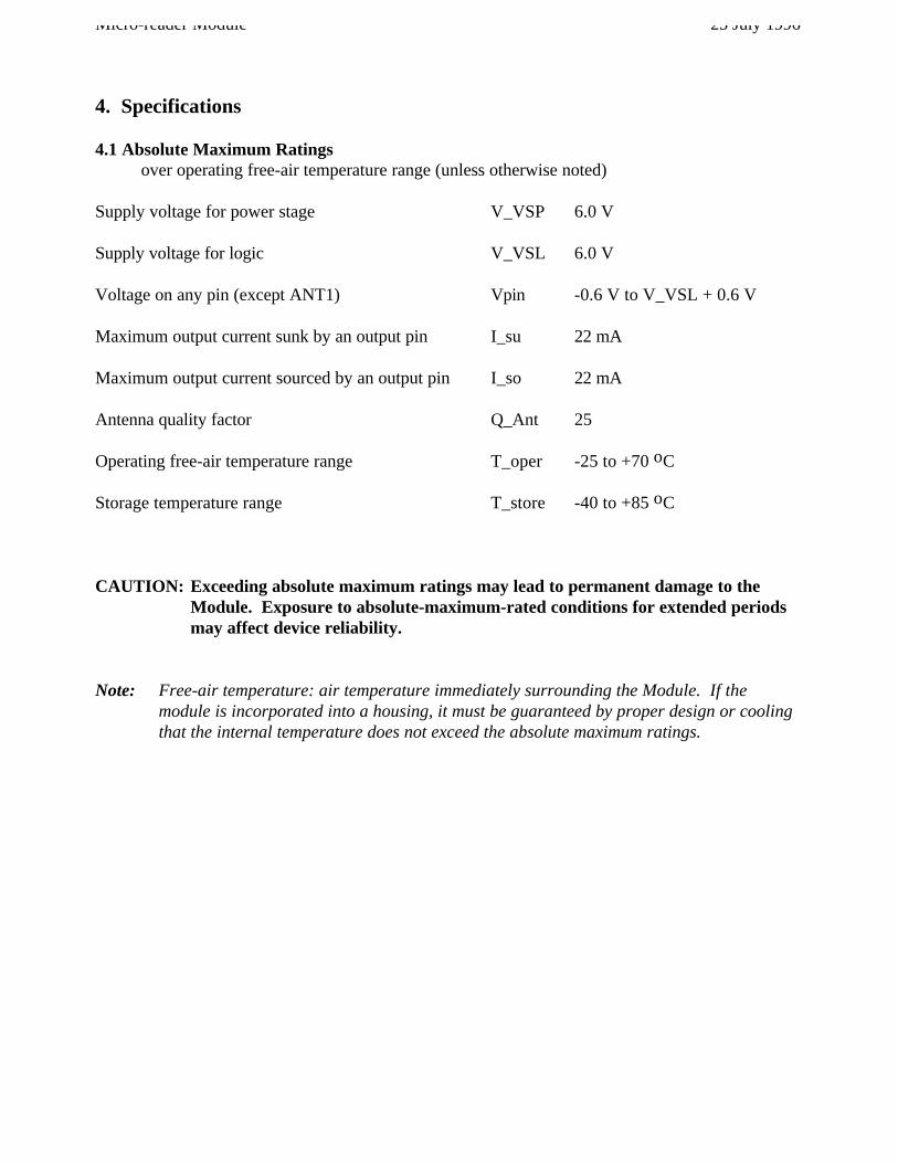
4.1 Absolute Maximum Ratingsover operating free-air temperature range (unless otherwise noted)
Supply voltage for power stage V_VSP 6.0 V
Supply voltage for logic V_VSL 6.0 V
Voltage on any pin (except ANT1) Vpin -0.6 V to V_VSL + 0.6 V
Maximum output current sunk by an output pin I_su 22 mA
Maximum output current sourced by an output pin I_so 22 mA
Antenna quality factor Q_Ant 25
Operating free-air temperature range T_oper -25 to +70 oC
Storage temperature range T_store -40 to +85 oC
CAUTION: Exceeding absolute maximum ratings may lead to permanent damage to theModule. Exposure to absolute-maximum-rated conditions for extended periodsmay affect device reliability.
Note: Free-air temperature: air temperature immediately surrounding the Module. If themodule is incorporated into a housing, it must be guaranteed by proper design or coolingthat the internal temperature does not exceed the absolute maximum ratings.
25 July 1996 Micro-reader Module
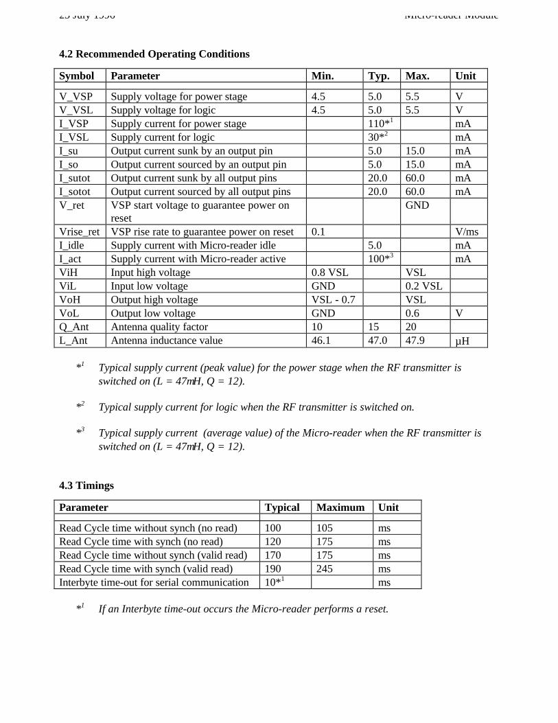
4.2 Recommended Operating Conditions
Symbol Parameter Min. Typ. Max. Unit
V_VSP Supply voltage for power stage 4.5 5.0 5.5 VV_VSL Supply voltage for logic 4.5 5.0 5.5 VI_VSP Supply current for power stage 110*1 mAI_VSL Supply current for logic 30*2 mAI_su Output current sunk by an output pin 5.0 15.0 mAI_so Output current sourced by an output pin 5.0 15.0 mAI_sutot Output current sunk by all output pins 20.0 60.0 mAI_sotot Output current sourced by all output pins 20.0 60.0 mAV_ret VSP start voltage to guarantee power on
resetGND
Vrise_ret VSP rise rate to guarantee power on reset 0.1 V/msI_idle Supply current with Micro-reader idle 5.0 mAI_act Supply current with Micro-reader active 100*3 mAViH Input high voltage 0.8 VSL VSLViL Input low voltage GND 0.2 VSLVoH Output high voltage VSL - 0.7 VSLVoL Output low voltage GND 0.6 VQ_Ant Antenna quality factor 10 15 20L_Ant Antenna inductance value 46.1 47.0 47.9 µH
*1 Typical supply current (peak value) for the power stage when the RF transmitter isswitched on (L = 47µH, Q = 12).
*2 Typical supply current for logic when the RF transmitter is switched on.
*3 Typical supply current (average value) of the Micro-reader when the RF transmitter isswitched on (L = 47µH, Q = 12).
4.3 Timings
Parameter Typical Maximum Unit
Read Cycle time without synch (no read) 100 105 msRead Cycle time with synch (no read) 120 175 msRead Cycle time without synch (valid read) 170 175 msRead Cycle time with synch (valid read) 190 245 msInterbyte time-out for serial communication 10*1 ms
*1 If an Interbyte time-out occurs the Micro-reader performs a reset.
Micro-reader Module 25 July 1996
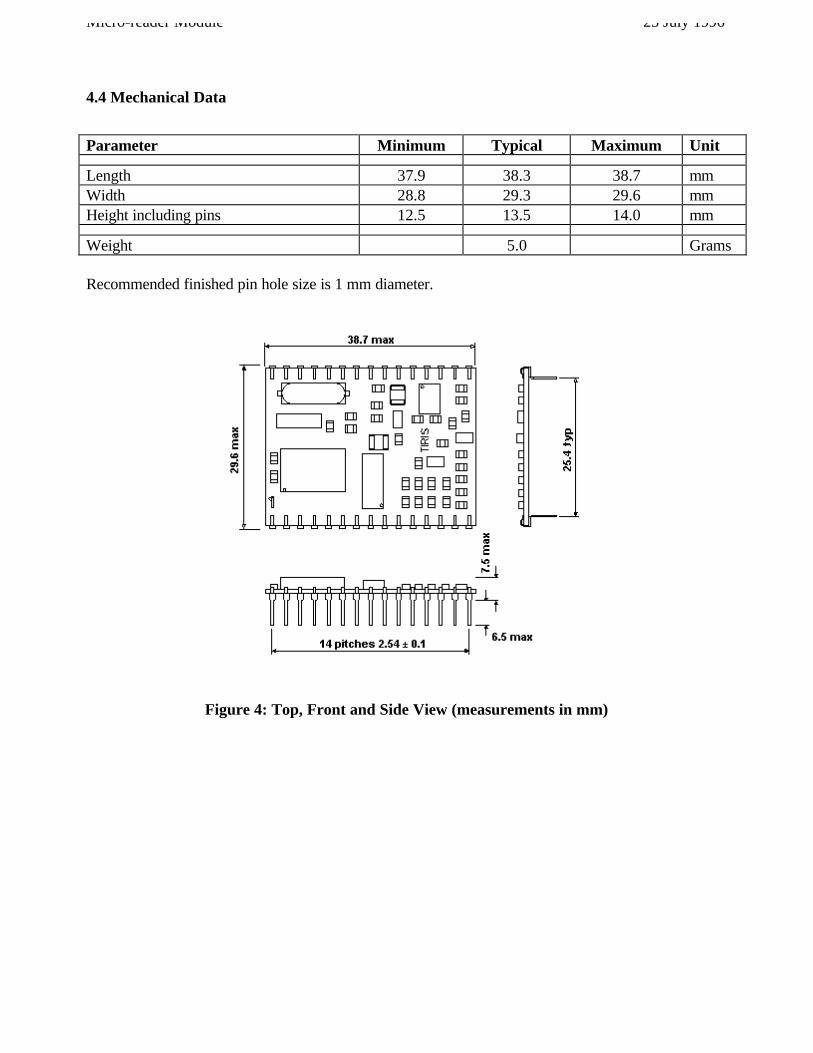
4.4 Mechanical Data
Parameter Minimum Typical Maximum Unit
Length 37.9 38.3 38.7 mmWidth 28.8 29.3 29.6 mmHeight including pins 12.5 13.5 14.0 mm
Weight 5.0 Grams
Recommended finished pin hole size is 1 mm diameter.
Figure 4: Top, Front and Side View (measurements in mm)
25 July 1996 Micro-reader Module
5. Transponder Protocols
5.1 Transponder commands
This section describes the protocols that need to be sent by the PC to the transponder via the Micro-reader in order to execute the required function.
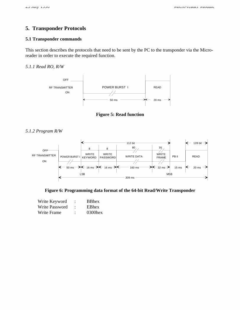
5.1.1 Read RO, R/W
OFF
ON
READ
50 ms 20 ms
RF TRANSMITTER POWER BURST I
Figure 5: Read function
5.1.2 Program R/W
READ
20 ms50 ms
WRITEKEYWORD
8 80 16
16 ms 160 ms 32 ms 15 ms
PASSWORD
8
16 ms
112 bit
309 ms
WRITE WRITEFRAMEWRITE DATA
128 bit
LSB MSB
OFF
ON
POWER BURST I PB IIRF TRANSMITTER
Figure 6: Programming data format of the 64-bit Read/Write Transponder
Write Keyword : BBhexWrite Password : EBhexWrite Frame : 0300hex
Micro-reader Module 25 July 1996
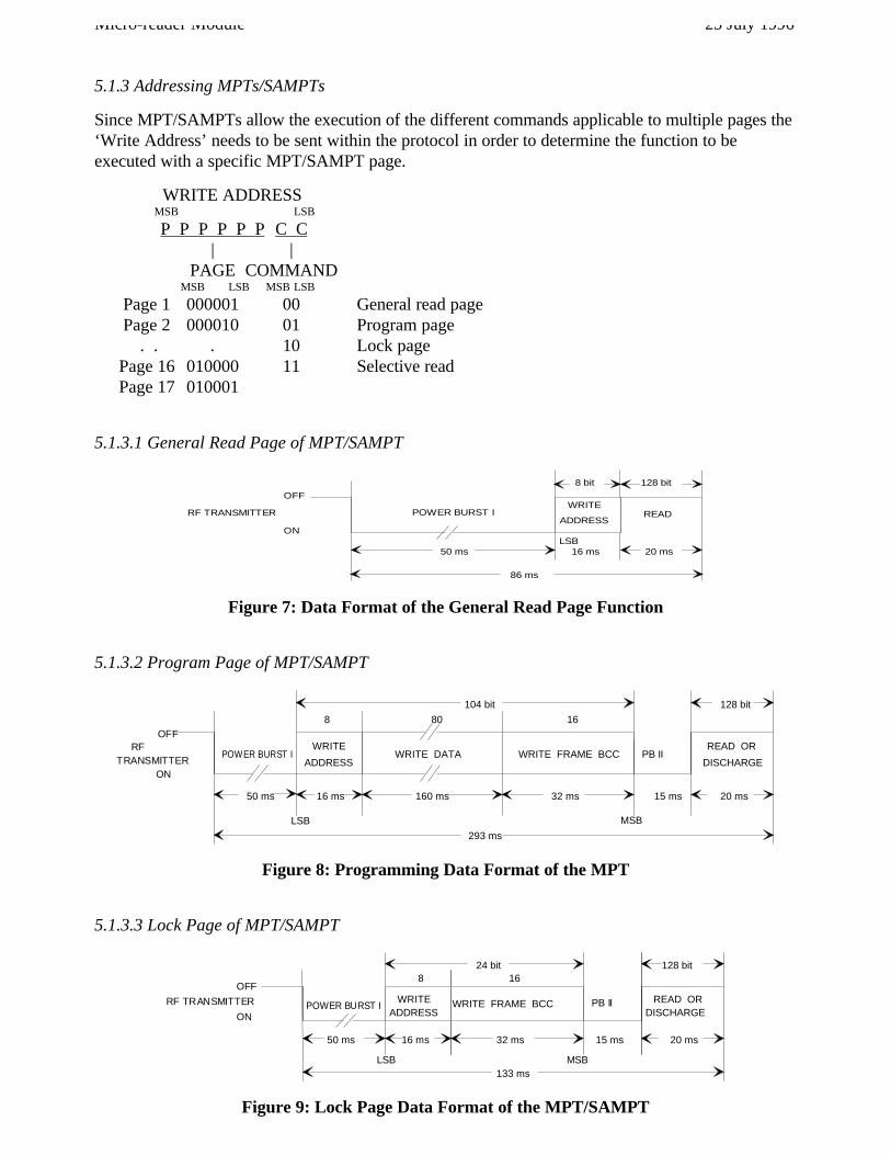
5.1.3 Addressing MPTs/SAMPTs
Since MPT/SAMPTs allow the execution of the different commands applicable to multiple pages the‘Write Address’ needs to be sent within the protocol in order to determine the function to beexecuted with a specific MPT/SAMPT page.
WRITE ADDRESSMSB LSB
P P P P P P C C| |
PAGE COMMANDMSB LSB MSB LSB
Page 1 000001 00 General read pagePage 2 000010 01 Program page
. . . 10 Lock page Page 16 010000 11 Selective read
Page 17 010001
5.1.3.1 General Read Page of MPT/SAMPT
50 ms
READWRITE
ADDRESS
86 ms
LSB
8 bit 128 bit
20 ms16 ms
ON
OFF
POWER BURST IRF TRANSMITTER
Figure 7: Data Format of the General Read Page Function
5.1.3.2 Program Page of MPT/SAMPT
READ OR
20 ms50 ms
WRITE
ADDRESSWRITE DATA WRITE FRAME BCC
8 80 16
16 ms 160 ms 32 ms 15 ms
293 ms
104 bit 128 bit
LSB
DISCHARGE
MSB
RFOFF
ONTRANSMITTER
POWER BURST I PB II
Figure 8: Programming Data Format of the MPT
5.1.3.3 Lock Page of MPT/SAMPT
50 ms
WRITEADDRESS
8
WRITE FRAME BCC
16
32 ms
133 ms
24 bit
READ OR
20 ms
128 bit
DISCHARGE
15 ms
LSB
16 ms
MSB
ON
OFF
POWER BURST IRF TRANSMITTER PB II
Figure 9: Lock Page Data Format of the MPT/SAMPT
25 July 1996 Micro-reader Module
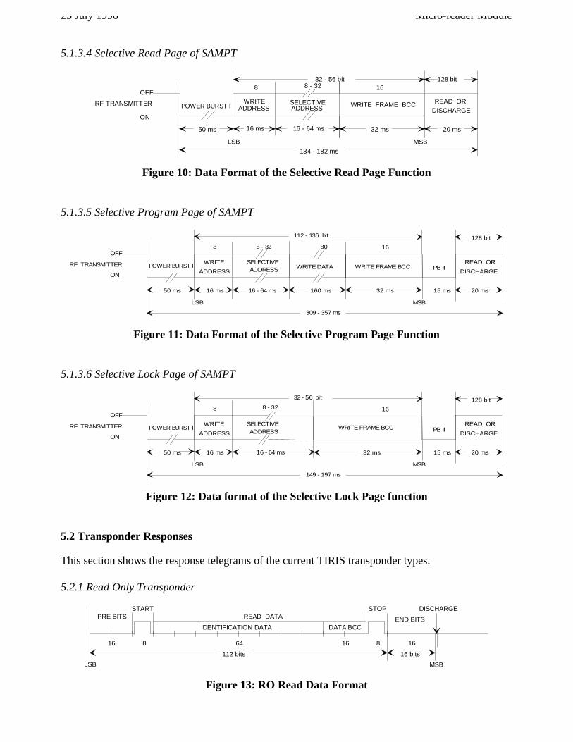
5.1.3.4 Selective Read Page of SAMPT
50 ms
WRITEADDRESS
8
WRITE FRAME BCC
16
32 ms
READ OR
20 ms
128 bit
DISCHARGE
LSB MSB
16 ms
SELECTIVEADDRESS
ON
OFF
RF TRANSMITTER POWER BURST I
8 - 32
16 - 64 ms
134 - 182 ms
32 - 56 bit
Figure 10: Data Format of the Selective Read Page Function
5.1.3.5 Selective Program Page of SAMPT
50 ms
WRITE
ADDRESS
8
16 ms
READ OR
20 ms
80 16
160 ms 32 ms 15 ms
128 bit
LSB
DISCHARGEWRITE FRAME BCCWRITE DATA
MSB
ADDRESSSELECTIVE
ON
OFF
RF TRANSMITTER POWER BURST I PB II
309 - 357 ms
112 - 136 bit
8 - 32
16 - 64 ms
Figure 11: Data Format of the Selective Program Page Function
5.1.3.6 Selective Lock Page of SAMPT
50 ms
WRITE
ADDRESS
8
16 ms
READ OR
20 ms
16
32 ms 15 ms
128 bit
LSB
DISCHARGEWRITE FRAME BCC
MSB
ADDRESSSELECTIVE
ON
OFF
RF TRANSMITTER POWER BURST I PB II
8 - 32
16 - 64 ms
32 - 56 bit
149 - 197 ms
Figure 12: Data format of the Selective Lock Page function
5.2 Transponder Responses
This section shows the response telegrams of the current TIRIS transponder types.
5.2.1 Read Only Transponder
START
816 8
STOP
64 16
DISCHARGE
LSB
PRE BITS END BITSIDENTIFICATION DATA DATA BCC
MSB
16 bits
16
112 bits
READ DATA
Figure 13: RO Read Data Format
Micro-reader Module 25 July 1996
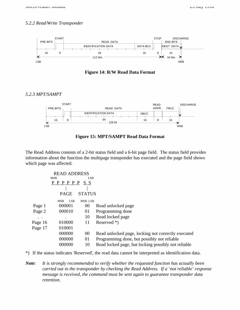
5.2.2 Read/Write Transponder
START
816 8
READ DATASTOP
64 16
DISCHARGE
15
LSB
PRE BITS END BITS
IDENTIFICATION DATA DATA BCC
MSB
112 bits 16 bits
IDENT. DATA
Figure 14: R/W Read Data Format
5.2.3 MPT/SAMPT
START
816 8 16
READ DATA ADDR.READ
128 bit64 16
LSB
IDENTIFICATION DATA
MSB
FBCC
DBCC
PRE BITSDISCHARGE
Figure 15: MPT/SAMPT Read Data Format
The Read Address consists of a 2-bit status field and a 6-bit page field. The status field providesinformation about the function the multipage transponder has executed and the page field showswhich page was affected.
READ ADDRESSMSB LSB
P P P P P P S S| |
PAGE STATUS
MSB LSB MSB LSB
Page 1 000001 00 Read unlocked pagePage 2 000010 01 Programming done
. . . 10 Read locked page Page 16 010000 11 Reserved *)
Page 17 010001000000 00 Read unlocked page, locking not correctly executed000000 01 Programming done, but possibly not reliable000000 10 Read locked page, but locking possibly not reliable
*) If the status indicates 'Reserved', the read data cannot be interpreted as identification data.
Note: It is strongly recommended to verify whether the requested function has actually beencarried out in the transponder by checking the Read Address. If a ‘not reliable’ responsemessage is received, the command must be sent again to guarantee transponder dataretention.
25 July 1996 Micro-reader Module
6. Communication Protocol Examples
6.1 PC to Micro-reader
Read RO, R/W
Byte Content (hex) Comment Description0 01 Start Mark1 02 Length Two bytes follow excluding BCC2 08 Command Field (1) Perform Single command, send Power Burst I3 32 Data Field (1) Power Burst I with 50 ms duration (charge-up)4 38 BCC BCC over previous bytes excluding Start Mark
General Read Page of MPT
The following sequence of bytes reads page 2 of an MPT.
Byte Content (hex) Comment Description0 01 Start Mark1 04 Length Four bytes follow excluding BCC2 48 Command Field (1) Perform Single command, send Power Burst I with data3 32 Data Field (1) Power Burst I with 50 ms duration (charge-up)4 01 Data Field (2) One Data Field follows5 08 Data Field (3) Write Address specifying General Read Page 26 77 BCC BCC over previous bytes excluding Start Mark
Program Page of MPT
The following sequence of bytes programs page 2 of an MPT with:00 00 00 00 00 2D C6 47
MSByte LSByte
Byte Content (hex) Comment Description0 01 Start Mark1 0F Length 15 bytes follow excluding BCC2 6C Command Field (1) Perform Single command, calculate FBCC,
send Power Burst I & II with Data3 32 Data Field (1) Power Burst I with 50 ms duration (charge-up)4 0F Data Field (2) Power Burst II with 15 ms duration (Progr. burst)5 0B Data Field (3) 11 Data Fields follow6 09 Data Field (4) Write Address specifying Program Page 27 47 Data Field (5) Programming data (LSByte)8 C6 Data Field (6) Programming data9 2D - : - - : -10 00 - : - - : -11 00 - : - - : -12 00 - : - - : -13 00 Data Field (11) Programming data14 00 Data Field (12) Programming data (MSByte)15 96 Data Field (13) DBCC (LSByte)16 50 Data Field (14) DBCC (MSByte)17 36 BCC BCC over previous bytes excluding Start Mark
Micro-reader Module 25 July 1996
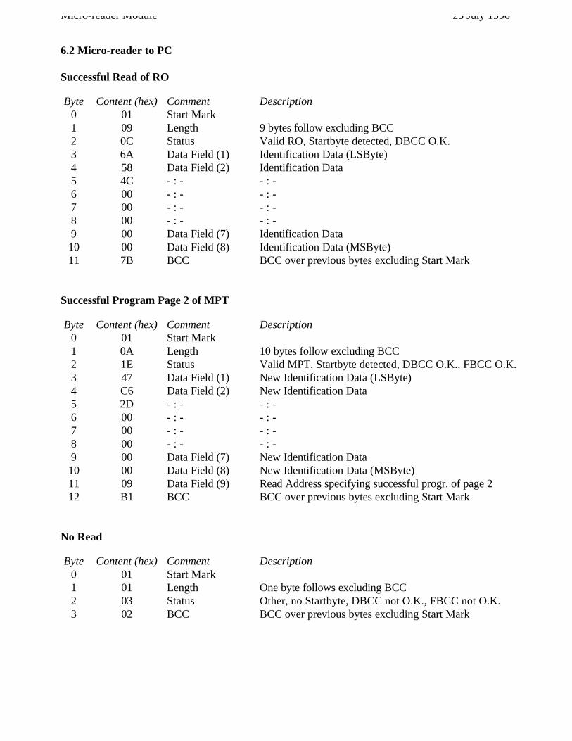
6.2 Micro-reader to PC
Successful Read of RO
Byte Content (hex) Comment Description0 01 Start Mark1 09 Length 9 bytes follow excluding BCC2 0C Status Valid RO, Startbyte detected, DBCC O.K.3 6A Data Field (1) Identification Data (LSByte)4 58 Data Field (2) Identification Data5 4C - : - - : -6 00 - : - - : -7 00 - : - - : -8 00 - : - - : -9 00 Data Field (7) Identification Data10 00 Data Field (8) Identification Data (MSByte)11 7B BCC BCC over previous bytes excluding Start Mark
Successful Program Page 2 of MPT
Byte Content (hex) Comment Description0 01 Start Mark1 0A Length 10 bytes follow excluding BCC2 1E Status Valid MPT, Startbyte detected, DBCC O.K., FBCC O.K.3 47 Data Field (1) New Identification Data (LSByte)4 C6 Data Field (2) New Identification Data5 2D - : - - : -6 00 - : - - : -7 00 - : - - : -8 00 - : - - : -9 00 Data Field (7) New Identification Data10 00 Data Field (8) New Identification Data (MSByte)11 09 Data Field (9) Read Address specifying successful progr. of page 212 B1 BCC BCC over previous bytes excluding Start Mark
No Read
Byte Content (hex) Comment Description0 01 Start Mark1 01 Length One byte follows excluding BCC2 03 Status Other, no Startbyte, DBCC not O.K., FBCC not O.K.3 02 BCC BCC over previous bytes excluding Start Mark
25 July 1996 Micro-reader Module
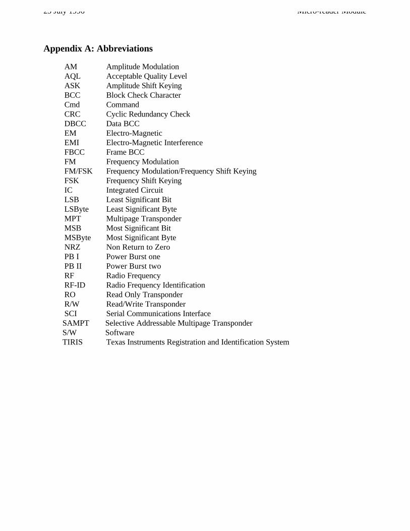
Appendix A: Abbreviations
AM Amplitude ModulationAQL Acceptable Quality LevelASK Amplitude Shift KeyingBCC Block Check CharacterCmd CommandCRC Cyclic Redundancy CheckDBCC Data BCCEM Electro-MagneticEMI Electro-Magnetic InterferenceFBCC Frame BCCFM Frequency ModulationFM/FSK Frequency Modulation/Frequency Shift KeyingFSK Frequency Shift KeyingIC Integrated CircuitLSB Least Significant BitLSByte Least Significant ByteMPT Multipage TransponderMSB Most Significant BitMSByte Most Significant ByteNRZ Non Return to ZeroPB I Power Burst onePB II Power Burst twoRF Radio FrequencyRF-ID Radio Frequency IdentificationRO Read Only TransponderR/W Read/Write TransponderSCI Serial Communications InterfaceSAMPT Selective Addressable Multipage TransponderS/W SoftwareTIRIS Texas Instruments Registration and Identification System
Micro-reader Module 25 July 1996
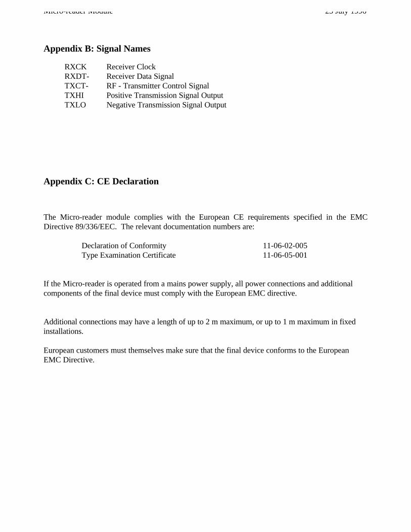
Appendix B: Signal Names
RXCK Receiver ClockRXDT- Receiver Data SignalTXCT- RF - Transmitter Control SignalTXHI Positive Transmission Signal OutputTXLO Negative Transmission Signal Output
Appendix C: CE Declaration
The Micro-reader module complies with the European CE requirements specified in the EMCDirective 89/336/EEC. The relevant documentation numbers are:
Declaration of Conformity 11-06-02-005Type Examination Certificate 11-06-05-001
If the Micro-reader is operated from a mains power supply, all power connections and additionalcomponents of the final device must comply with the European EMC directive.
Additional connections may have a length of up to 2 m maximum, or up to 1 m maximum in fixedinstallations.
European customers must themselves make sure that the final device conforms to the EuropeanEMC Directive.


![EID Reader Manual Installation Card Reader... · EID Reader Manual Installation [FAQ, Perquisite & Guides] Document Details EID Reader Manual Installation and Troubleshooting Software](https://static.fdocuments.in/doc/165x107/5e2b1bd34debb043f0778de5/eid-reader-manual-installation-card-reader-eid-reader-manual-installation-faq.jpg)


