TetGen - MITweb.mit.edu/tetgen_v1.4.1/tetgen-manual.pdf · The corresponding Delaunay triangulation...
62
TetGen A Quality Tetrahedral Mesh Generator and Three-Dimensional Delaunay Triangulator Version 1.4 User’s Manual January 18, 2006 Hang Si [email protected] http://tetgen.berlios.de c 2002, 2004, 2005, 2006
Transcript of TetGen - MITweb.mit.edu/tetgen_v1.4.1/tetgen-manual.pdf · The corresponding Delaunay triangulation...
TetGenA Quality Tetrahedral Mesh Generator andThree-Dimensional Delaunay Triangulator
Version 1.4
User’s Manual
January 18, 2006
Hang [email protected]
http://tetgen.berlios.de
c©2002, 2004, 2005, 2006
Abstract
TetGen generates tetrahedral meshes and Delaunay tetrahedral-izations. The tetrahedral meshes are suitable for finite element andfinite volume methods. The algorithms implemented are the state ofthe art.
This documents briefly explains the problems solved by TetGenand is a detailed user’s guide. Readers will learn how to create tetra-hedral meshes using input files from the command line. Furthermore,the programming interface for calling TetGen from other programs isexplained.
keywords: tetrahedral mesh, Delaunay tetrahedralization, con-strained Delaunay tetrahedralization, mesh quality, mesh generation
2
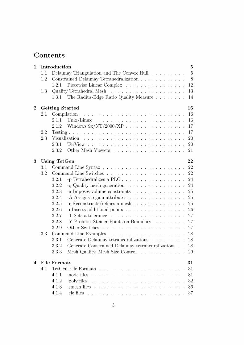
Contents
1 Introduction 51.1 Delaunay Triangulation and The Convex Hull . . . . . . . . . 51.2 Constrained Delaunay Tetrahedralization . . . . . . . . . . . . 8
1.2.1 Piecewise Linear Complex . . . . . . . . . . . . . . . . 121.3 Quality Tetrahedral Mesh . . . . . . . . . . . . . . . . . . . . 13
1.3.1 The Radius-Edge Ratio Quality Measure . . . . . . . . 14
2 Getting Started 162.1 Compilation . . . . . . . . . . . . . . . . . . . . . . . . . . . . 16
2.1.1 Unix/Linux . . . . . . . . . . . . . . . . . . . . . . . . 162.1.2 Windows 9x/NT/2000/XP . . . . . . . . . . . . . . . . 17
2.2 Testing . . . . . . . . . . . . . . . . . . . . . . . . . . . . . . . 172.3 Visualization . . . . . . . . . . . . . . . . . . . . . . . . . . . 20
2.3.1 TetView . . . . . . . . . . . . . . . . . . . . . . . . . . 202.3.2 Other Mesh Viewers . . . . . . . . . . . . . . . . . . . 21
3 Using TetGen 223.1 Command Line Syntax . . . . . . . . . . . . . . . . . . . . . . 223.2 Command Line Switches . . . . . . . . . . . . . . . . . . . . . 22
3.2.1 -p Tetrahedralizes a PLC . . . . . . . . . . . . . . . . . 243.2.2 -q Quality mesh generation . . . . . . . . . . . . . . . 243.2.3 -a Imposes volume constraints . . . . . . . . . . . . . . 253.2.4 -A Assigns region attributes . . . . . . . . . . . . . . . 253.2.5 -r Reconstructs/refines a mesh . . . . . . . . . . . . . . 253.2.6 -i Inserts additional points . . . . . . . . . . . . . . . . 263.2.7 -T Sets a tolerance . . . . . . . . . . . . . . . . . . . . 273.2.8 -Y Prohibit Steiner Points on Boundary . . . . . . . . 273.2.9 Other Switches . . . . . . . . . . . . . . . . . . . . . . 27
3.3 Command Line Examples . . . . . . . . . . . . . . . . . . . . 283.3.1 Generate Delaunay tetrahedralizations . . . . . . . . . 283.3.2 Generate Constrained Delaunay tetrahedralizations . . 283.3.3 Mesh Quality, Mesh Size Control . . . . . . . . . . . . 29
4 File Formats 314.1 TetGen File Formats . . . . . . . . . . . . . . . . . . . . . . . 31
4.1.1 .node files . . . . . . . . . . . . . . . . . . . . . . . . . 314.1.2 .poly files . . . . . . . . . . . . . . . . . . . . . . . . . 324.1.3 .smesh files . . . . . . . . . . . . . . . . . . . . . . . . 364.1.4 .ele files . . . . . . . . . . . . . . . . . . . . . . . . . . 37
3
4.1.5 .face files . . . . . . . . . . . . . . . . . . . . . . . . . . 384.1.6 .edge files . . . . . . . . . . . . . . . . . . . . . . . . . 384.1.7 .vol files . . . . . . . . . . . . . . . . . . . . . . . . . . 394.1.8 .var files . . . . . . . . . . . . . . . . . . . . . . . . . . 394.1.9 .neigh files . . . . . . . . . . . . . . . . . . . . . . . . . 40
4.2 Supported File Formats . . . . . . . . . . . . . . . . . . . . . 404.2.1 .off files . . . . . . . . . . . . . . . . . . . . . . . . . . 414.2.2 .ply files . . . . . . . . . . . . . . . . . . . . . . . . . . 414.2.3 .stl files . . . . . . . . . . . . . . . . . . . . . . . . . . 414.2.4 .mesh files . . . . . . . . . . . . . . . . . . . . . . . . . 42
4.3 File Format Examples . . . . . . . . . . . . . . . . . . . . . . 424.3.1 A PLC with Two Boundary Markers . . . . . . . . . . 424.3.2 A PLC with Two Regions . . . . . . . . . . . . . . . . 45
5 Calling TetGen from Another Program 485.1 The Header File . . . . . . . . . . . . . . . . . . . . . . . . . . 485.2 The Calling Convention . . . . . . . . . . . . . . . . . . . . . 485.3 The “tetgenio” Data Type . . . . . . . . . . . . . . . . . . . . 495.4 Description of Arrays . . . . . . . . . . . . . . . . . . . . . . . 50
5.4.1 Memory Management . . . . . . . . . . . . . . . . . . . 515.4.2 The “facet” Data Structure . . . . . . . . . . . . . . . 52
5.5 An Example . . . . . . . . . . . . . . . . . . . . . . . . . . . . 54
A Some Combinatorial Topology 58
References 59
4
1 Introduction
The TetGen program generates tetrahedral meshes from three-dimensionaldomains. The goal is to generate suitable tetrahedral meshes for numericalsimulation using finite element and finite volume methods. Besides, as atetrahedral mesh generator, it can be used as a meshing component in manyscientific and engineering applications.
For a three-dimensional domain, defined by its boundary (such as a sur-face mesh), TetGen generates the boundary constrained (Delaunay) tetra-hedralization, conforming (Delaunay) tetrahedralization, quality (Delaunay)mesh. The latter is nicely graded and the tetrahedra have circumradius-to-shortest-edge ratio bounded. For a three-dimensional point set, the Delaunaytetrahedralization and convex hull are generated.
The code, written in C++, may be compiled into an executable programor a library for integrating into other applications. All major operatingsystems, e.g. Unix/Linux, MacOS, Windows, etc, are supported.
The algorithms used in TetGen are of Delaunay type. The remainder ofthis section is to give a brief description of the mesh problems that TetGensolves. The algorithms implemented in TetGen are described. Referencesare given for people who are particularly interesting in these approaches.However, this information is not really crucial for all users. Most of thesections can be skipped but Section 1.2.1 and 1.3.1, which contain someimportant points to get a solvable problem.
1.1 Delaunay Triangulation and The Convex Hull
The Delaunay triangulation of a vertex set, introduced by Delaunay [1] in1934, has many favorable properties which make it be a useful geometricstructure. It has been used extensively both in the design of efficient algo-rithms and in practical applications.
The language of combinatorial topology will be used to describe Delaunaytriangulations. Understanding of some basic notions is necessary, such asconvex hull, simplex, simplical complex. A brief explanation of these notionsis provided in Appendix A.
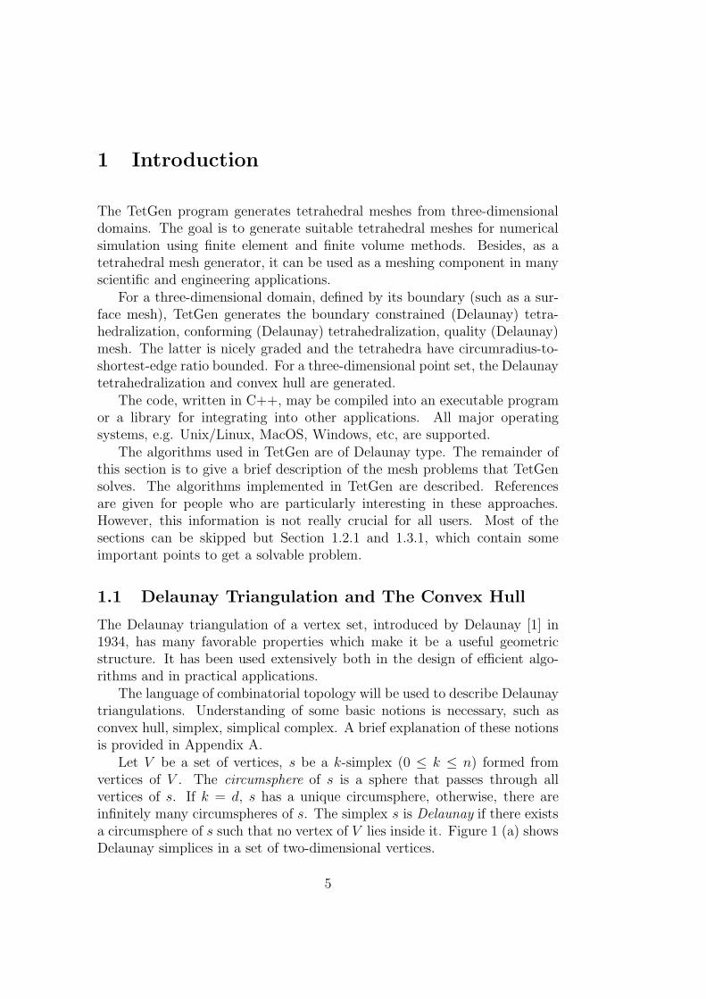
Let V be a set of vertices, s be a k-simplex (0 ≤ k ≤ n) formed fromvertices of V . The circumsphere of s is a sphere that passes through allvertices of s. If k = d, s has a unique circumsphere, otherwise, there areinfinitely many circumspheres of s. The simplex s is Delaunay if there existsa circumsphere of s such that no vertex of V lies inside it. Figure 1 (a) showsDelaunay simplices in a set of two-dimensional vertices.
5
a
b
c
d
e
a
b
c
d
e
(a) (b)
Figure 1: The Delaunay criterion and Delaunay triangulation in two dimen-sions. (a) Both the 2-simplex abc and the 1-simplex de are Delaunay. (b)The corresponding Delaunay triangulation of the point set shown in (a).
The Delaunay triangulation D of V is a simplical complex consisting ofDelaunay simplices, and the set of all simplices of D covers the convex hull ofV . A two-dimensional Delaunay triangulation is illustrated in Figure 1 (b).In three dimensions, it is also called Delaunay tetrahedralization.
A Delaunay triangulation in Rd corresponds to a convex hull in Rd+1. Forpoint p = (p1, p2, · · · , pd) ∈ Rd, define itslift point p+ = (p1, p2, · · · , pd, pd+1) ∈Rd+1, where pd+1 =
∑di=1 p2
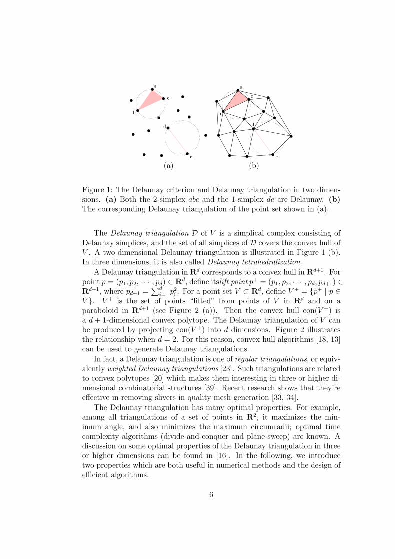
i . For a point set V ⊂ Rd, define V + = {p+ | p ∈V }. V + is the set of points “lifted” from points of V in Rd and on aparaboloid in Rd+1 (see Figure 2 (a)). Then the convex hull con(V +) isa d + 1-dimensional convex polytope. The Delaunay triangulation of V canbe produced by projecting con(V +) into d dimensions. Figure 2 illustratesthe relationship when d = 2. For this reason, convex hull algorithms [18, 13]can be used to generate Delaunay triangulations.
In fact, a Delaunay triangulation is one of regular triangulations, or equiv-alently weighted Delaunay triangulations [23]. Such triangulations are relatedto convex polytopes [20] which makes them interesting in three or higher di-mensional combinatorial structures [39]. Recent research shows that they’reeffective in removing slivers in quality mesh generation [33, 34].
The Delaunay triangulation has many optimal properties. For example,among all triangulations of a set of points in R2, it maximizes the min-imum angle, and also minimizes the maximum circumradii; optimal timecomplexity algorithms (divide-and-conquer and plane-sweep) are known. Adiscussion on some optimal properties of the Delaunay triangulation in threeor higher dimensions can be found in [16]. In the following, we introducetwo properties which are both useful in numerical methods and the design ofefficient algorithms.
6
p
p+
z
x/1.0e-01y/1.0e-01
(a) (b)
Figure 2: The relation between Delaunay triangulation in Rd and convexhull in Rd+1 (here d = 2). (a) Some 2D points and their corresponding 3Dlift points. (b) The Delaunay triangulation of a set of 2D points and thelower convex hull of its 3D lifted points.
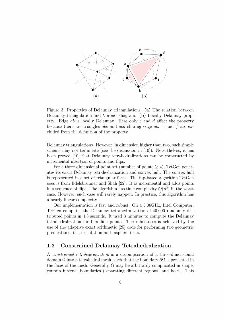
The dual of the Delaunay triangulation is the Voronoi diagram definedon the same vertex set. For any vertex a ∈ V , the Voronoi cell of a is theset of points with distance to a not greater than to any other vertex of V ,i.e. it is the set {x ∈ Rn | |x − a| ≤ |x − b|, ∀b ∈ V }, where | · | standsfor the Euclidean distance. The Voronoi diagram of V is a subdivision ofspace Rn into Voronoi cells (some of which may be unbounded). Delaunaytriangulation and Voronoi diagram are geometrically dual. For example, intwo dimensions, Voronoi polygons correspond to Delaunay vertices, Voronoiedges correspond to Delaunay edges, and Voronoi vertices correspond to De-launay triangles (illustrated in Figure 3 (a)).
Another useful property is the localization of the Delaunay property. LetT be an arbitrary triangulation of V , and s be a simplex of T . Let K bea subcomplex of T formed by simplices containing s. s is locally Delaunayif there exists a circumsphere of s enclosing no vertices from the vertex setof K in its interior. Figure 3 (b) illustrates the property in two dimensions.Evidently, if every simplex of T is locally Delaunay, then T is Delaunaytriangulation.
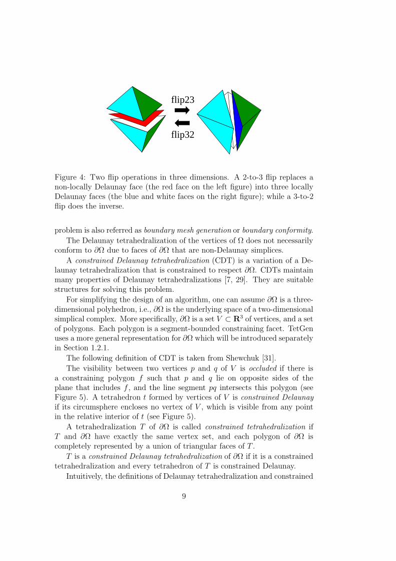
It is well known that the Delaunay triangulations can be constructed by“flips”. A flip is an operation to transform a set of non-locally Delaunaysimplices into another set of simplices which are locally Delaunay. Figure 4illustrates two types of flips in three dimensions. The basic idea of flip-based algorithms is relatively simple: start from an arbitrary triangulation,flip simplices that are not locally Delaunay, until all simplices are locallyDelaunay. The result is a Delaunay triangulation due to the fact mentionedabove. Lawson [5] first used a flip algorithm to construct two-dimensional
7
a
b
c
de
f
(a) (b)
Figure 3: Properties of Delaunay triangulations. (a) The relation betweenDelaunay triangulation and Voronoi diagram. (b) Locally Delaunay prop-erty. Edge ab is locally Delaunay. Here only c and d affect the propertybecause there are triangles abc and abd sharing edge ab. e and f are ex-cluded from the definition of the property.
Delaunay triangulations. However, in dimension higher than two, such simplescheme may not terminate (see the discussion in [10]). Nevertheless, it hasbeen proved [10] that Delaunay tetrahedralizations can be constructed byincremental insertion of points and flips.
For a three-dimensional point set (number of points ≥ 4), TetGen gener-ates its exact Delaunay tetrahedralization and convex hull. The convex hullis represented in a set of triangular faces. The flip-based algorithm TetGenuses is from Edelsbrunner and Shah [22]. It is incremental and adds pointsin a sequence of flips. The algorithm has time complexity O(n2) in the worstcase. However, such case will rarely happen. In practice, this algorithm hasa nearly linear complexity.
Our implementation is fast and robust. On a 3.06GHz, Intel Computer,TetGen computes the Delaunay tetrahedralization of 40,000 randomly dis-tributed points in 4.8 seconds. It used 3 minutes to compute the Delaunaytetrahedralization for 1 million points. The robustness is achieved by theuse of the adaptive exact arithmetic [25] code for performing two geometricpredications, i.e., orientation and insphere tests.
1.2 Constrained Delaunay Tetrahedralization
A constrained tetrahedralization is a decomposition of a three-dimensionaldomain Ω into a tetrahedral mesh, such that the boundary ∂Ω is presented inthe faces of the mesh. Generally, Ω may be arbitrarily complicated in shape,contain internal boundaries (separating different regions) and holes. This
8
flip23
flip32
Figure 4: Two flip operations in three dimensions. A 2-to-3 flip replaces anon-locally Delaunay face (the red face on the left figure) into three locallyDelaunay faces (the blue and white faces on the right figure); while a 3-to-2flip does the inverse.
problem is also referred as boundary mesh generation or boundary conformity.
The Delaunay tetrahedralization of the vertices of Ω does not necessarilyconform to ∂Ω due to faces of ∂Ω that are non-Delaunay simplices.
A constrained Delaunay tetrahedralization (CDT) is a variation of a De-launay tetrahedralization that is constrained to respect ∂Ω. CDTs maintainmany properties of Delaunay tetrahedralizations [7, 29]. They are suitablestructures for solving this problem.
For simplifying the design of an algorithm, one can assume ∂Ω is a three-dimensional polyhedron, i.e., ∂Ω is the underlying space of a two-dimensionalsimplical complex. More specifically, ∂Ω is a set V ⊂ R3 of vertices, and a setof polygons. Each polygon is a segment-bounded constraining facet. TetGenuses a more general representation for ∂Ω which will be introduced separatelyin Section 1.2.1.
The following definition of CDT is taken from Shewchuk [31].
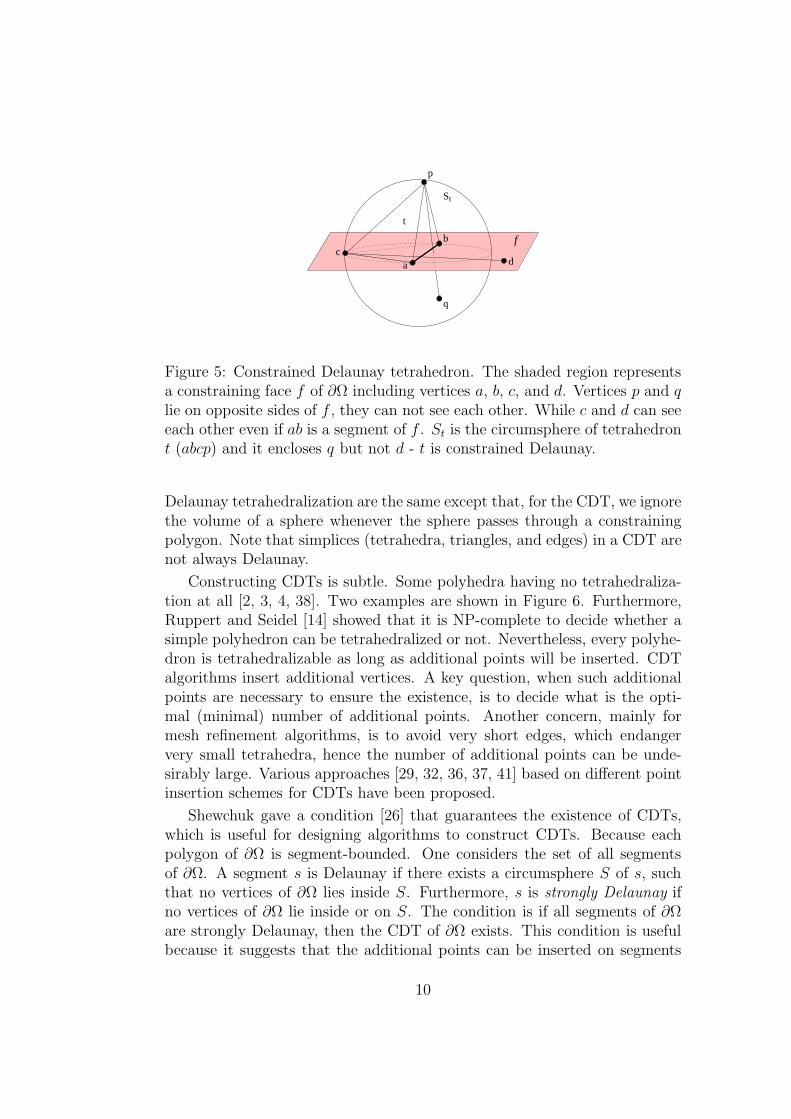
The visibility between two vertices p and q of V is occluded if there isa constraining polygon f such that p and q lie on opposite sides of theplane that includes f , and the line segment pq intersects this polygon (seeFigure 5). A tetrahedron t formed by vertices of V is constrained Delaunayif its circumsphere encloses no vertex of V , which is visible from any pointin the relative interior of t (see Figure 5).
A tetrahedralization T of ∂Ω is called constrained tetrahedralization ifT and ∂Ω have exactly the same vertex set, and each polygon of ∂Ω iscompletely represented by a union of triangular faces of T .
T is a constrained Delaunay tetrahedralization of ∂Ω if it is a constrainedtetrahedralization and every tetrahedron of T is constrained Delaunay.
Intuitively, the definitions of Delaunay tetrahedralization and constrained
9
a
p
b
S
q
dc
t
t
f
Figure 5: Constrained Delaunay tetrahedron. The shaded region representsa constraining face f of ∂Ω including vertices a, b, c, and d. Vertices p and qlie on opposite sides of f , they can not see each other. While c and d can seeeach other even if ab is a segment of f . St is the circumsphere of tetrahedront (abcp) and it encloses q but not d - t is constrained Delaunay.
Delaunay tetrahedralization are the same except that, for the CDT, we ignorethe volume of a sphere whenever the sphere passes through a constrainingpolygon. Note that simplices (tetrahedra, triangles, and edges) in a CDT arenot always Delaunay.
Constructing CDTs is subtle. Some polyhedra having no tetrahedraliza-tion at all [2, 3, 4, 38]. Two examples are shown in Figure 6. Furthermore,Ruppert and Seidel [14] showed that it is NP-complete to decide whether asimple polyhedron can be tetrahedralized or not. Nevertheless, every polyhe-dron is tetrahedralizable as long as additional points will be inserted. CDTalgorithms insert additional vertices. A key question, when such additionalpoints are necessary to ensure the existence, is to decide what is the opti-mal (minimal) number of additional points. Another concern, mainly formesh refinement algorithms, is to avoid very short edges, which endangervery small tetrahedra, hence the number of additional points can be unde-sirably large. Various approaches [29, 32, 36, 37, 41] based on different pointinsertion schemes for CDTs have been proposed.
Shewchuk gave a condition [26] that guarantees the existence of CDTs,which is useful for designing algorithms to construct CDTs. Because eachpolygon of ∂Ω is segment-bounded. One considers the set of all segmentsof ∂Ω. A segment s is Delaunay if there exists a circumsphere S of s, suchthat no vertices of ∂Ω lies inside S. Furthermore, s is strongly Delaunay ifno vertices of ∂Ω lie inside or on S. The condition is if all segments of ∂Ωare strongly Delaunay, then the CDT of ∂Ω exists. This condition is usefulbecause it suggests that the additional points can be inserted on segments
10
(a) (b)
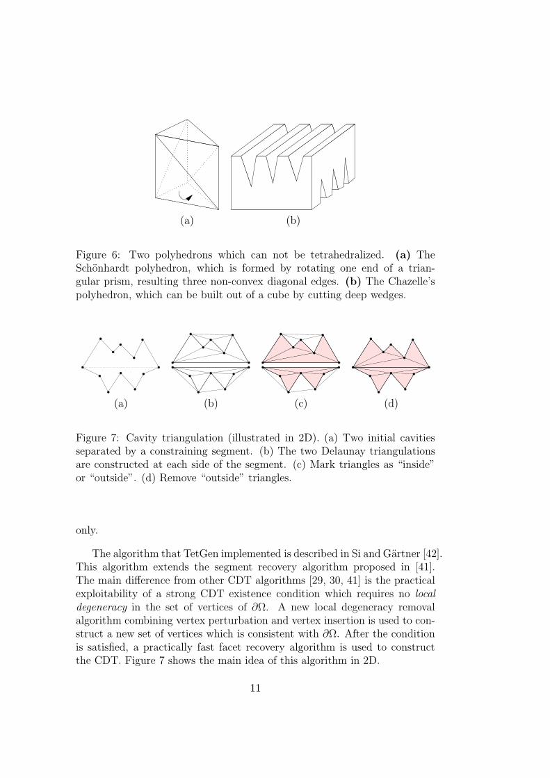
Figure 6: Two polyhedrons which can not be tetrahedralized. (a) TheSchonhardt polyhedron, which is formed by rotating one end of a trian-gular prism, resulting three non-convex diagonal edges. (b) The Chazelle’spolyhedron, which can be built out of a cube by cutting deep wedges.
(a) (b) (c) (d)
Figure 7: Cavity triangulation (illustrated in 2D). (a) Two initial cavitiesseparated by a constraining segment. (b) The two Delaunay triangulationsare constructed at each side of the segment. (c) Mark triangles as “inside”or “outside”. (d) Remove “outside” triangles.
only.
The algorithm that TetGen implemented is described in Si and Gartner [42].This algorithm extends the segment recovery algorithm proposed in [41].The main difference from other CDT algorithms [29, 30, 41] is the practicalexploitability of a strong CDT existence condition which requires no localdegeneracy in the set of vertices of ∂Ω. A new local degeneracy removalalgorithm combining vertex perturbation and vertex insertion is used to con-struct a new set of vertices which is consistent with ∂Ω. After the conditionis satisfied, a practically fast facet recovery algorithm is used to constructthe CDT. Figure 7 shows the main idea of this algorithm in 2D.
11
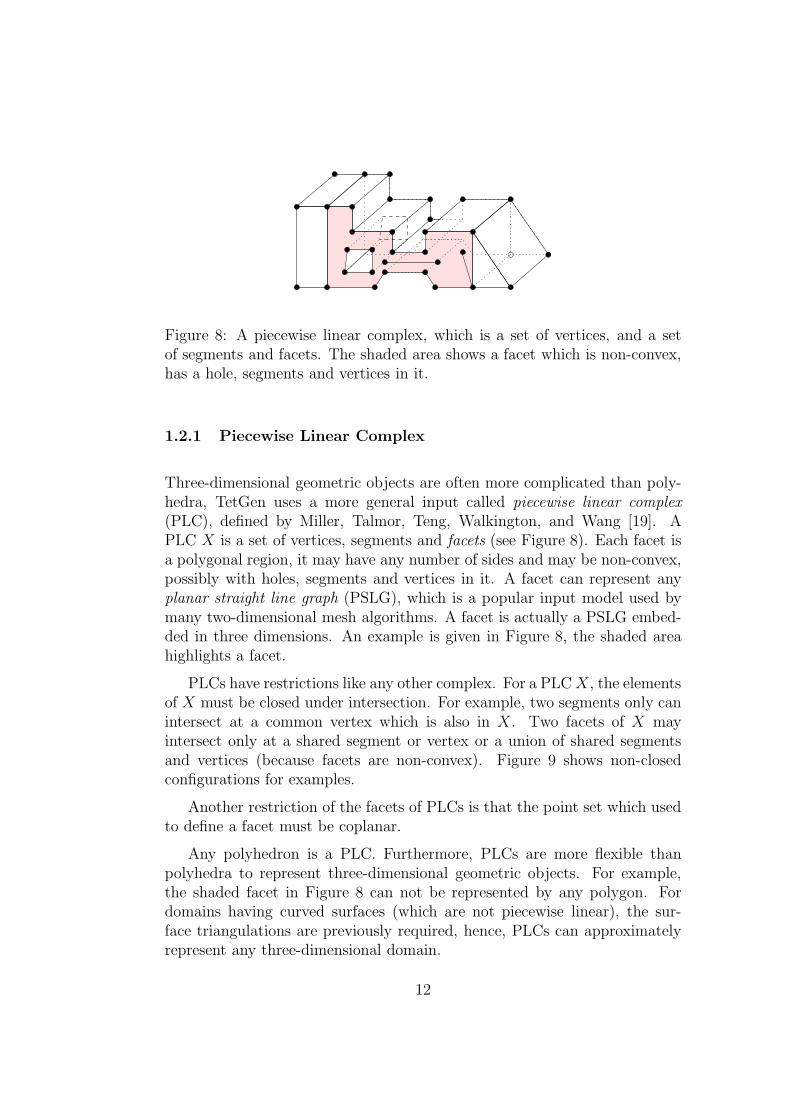
Figure 8: A piecewise linear complex, which is a set of vertices, and a setof segments and facets. The shaded area shows a facet which is non-convex,has a hole, segments and vertices in it.
1.2.1 Piecewise Linear Complex
Three-dimensional geometric objects are often more complicated than poly-hedra, TetGen uses a more general input called piecewise linear complex(PLC), defined by Miller, Talmor, Teng, Walkington, and Wang [19]. APLC X is a set of vertices, segments and facets (see Figure 8). Each facet isa polygonal region, it may have any number of sides and may be non-convex,possibly with holes, segments and vertices in it. A facet can represent anyplanar straight line graph (PSLG), which is a popular input model used bymany two-dimensional mesh algorithms. A facet is actually a PSLG embed-ded in three dimensions. An example is given in Figure 8, the shaded areahighlights a facet.
PLCs have restrictions like any other complex. For a PLC X, the elementsof X must be closed under intersection. For example, two segments only canintersect at a common vertex which is also in X. Two facets of X mayintersect only at a shared segment or vertex or a union of shared segmentsand vertices (because facets are non-convex). Figure 9 shows non-closedconfigurations for examples.
Another restriction of the facets of PLCs is that the point set which usedto define a facet must be coplanar.
Any polyhedron is a PLC. Furthermore, PLCs are more flexible thanpolyhedra to represent three-dimensional geometric objects. For example,the shaded facet in Figure 8 can not be represented by any polygon. Fordomains having curved surfaces (which are not piecewise linear), the sur-face triangulations are previously required, hence, PLCs can approximatelyrepresent any three-dimensional domain.
12
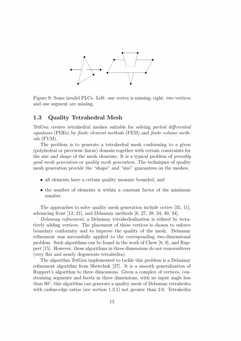
Figure 9: Some invalid PLCs. Left: one vertex is missing; right: two verticesand one segment are missing.
1.3 Quality Tetrahedral Mesh
TetGen creates tetrahedral meshes suitable for solving partial differentialequations (PDEs) by finite element methods (FEM) and finite volume meth-ods (FVM).
The problem is to generate a tetrahedral mesh conforming to a given(polyhedral or piecewise linear) domain together with certain constraints forthe size and shape of the mesh elements. It is a typical problem of provablygood mesh generation or quality mesh generation. The techniques of qualitymesh generation provide the “shape” and “size” guarantees on the meshes:
• all elements have a certain quality measure bounded, and
• the number of elements is within a constant factor of the minimumnumber.
The approaches to solve quality mesh generation include octree [35, 11],advancing front [12, 21], and Delaunay methods [6, 27, 28, 24, 40, 34].
Delaunay refinement, a Delaunay tetrahedralization is refined by itera-tively adding vertices. The placement of these vertices is chosen to enforceboundary conformity and to improve the quality of the mesh. Delaunayrefinement was successfully applied to the corresponding two-dimensionalproblem. Such algorithms can be found in the work of Chew [8, 9], and Rup-pert [15]. However, these algorithms in three dimensions do not removeslivers(very flat and nearly degenerate tetrahedra).
The algorithm TetGen implemented to tackle this problem is a Delaunayrefinement algorithm from Shewchuk [27]. It is a smooth generalization ofRuppert’s algorithm to three dimensions. Given a complex of vertices, con-straining segments and facets in three dimensions, with no input angle lessthan 90◦, this algorithm can generate a quality mesh of Delaunay tetrahedrawith radius-edge ratios (see section 1.3.1) not greater than 2.0. Tetrahedra
13
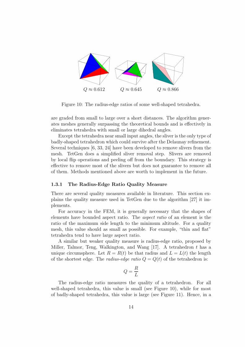
Q ≈ 0.612 Q ≈ 0.645 Q ≈ 0.866
Figure 10: The radius-edge ratios of some well-shaped tetrahedra.
are graded from small to large over a short distances. The algorithm gener-ates meshes generally surpassing the theoretical bounds and is effectively ineliminates tetrahedra with small or large dihedral angles.
Except the tetrahedra near small input angles, the sliver is the only type ofbadly-shaped tetrahedron which could survive after the Delaunay refinement.Several techniques [6, 33, 24] have been developed to remove slivers from themesh. TetGen does a simplified sliver removal step. Slivers are removedby local flip operations and peeling off from the boundary. This strategy iseffective to remove most of the slivers but does not guarantee to remove allof them. Methods mentioned above are worth to implement in the future.
1.3.1 The Radius-Edge Ratio Quality Measure
There are several quality measures available in literature. This section ex-plains the quality measure used in TetGen due to the algorithm [27] it im-plements.
For accuracy in the FEM, it is generally necessary that the shapes ofelements have bounded aspect ratio. The aspect ratio of an element is theratio of the maximum side length to the minimum altitude. For a qualitymesh, this value should as small as possible. For example, “thin and flat”tetrahedra tend to have large aspect ratio.
A similar but weaker quality measure is radius-edge ratio, proposed byMiller, Talmor, Teng, Walkington, and Wang [17]. A tetrahedron t has aunique circumsphere. Let R = R(t) be that radius and L = L(t) the lengthof the shortest edge. The radius-edge ratio Q = Q(t) of the tetrahedron is:
Q =R
L
The radius-edge ratio measures the quality of a tetrahedron. For allwell-shaped tetrahedra, this value is small (see Figure 10), while for mostof badly-shaped tetrahedra, this value is large (see Figure 11). Hence, in a
14
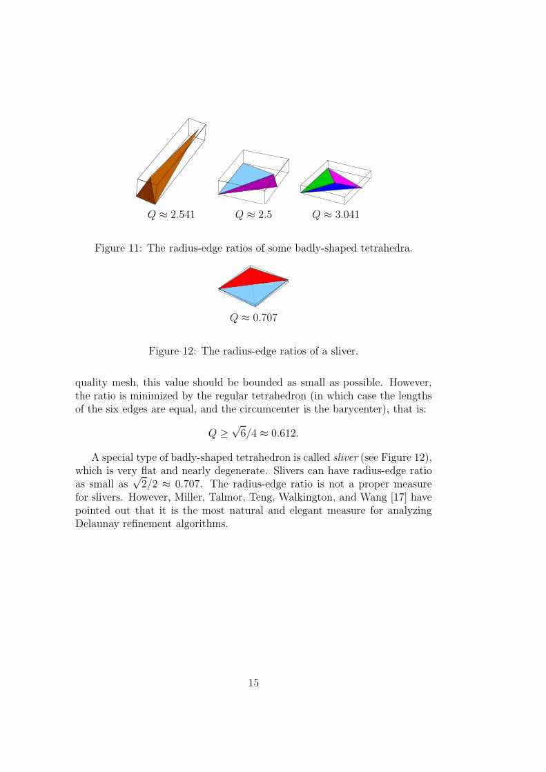
Q ≈ 2.541 Q ≈ 2.5 Q ≈ 3.041
Figure 11: The radius-edge ratios of some badly-shaped tetrahedra.
Q ≈ 0.707
Figure 12: The radius-edge ratios of a sliver.
quality mesh, this value should be bounded as small as possible. However,the ratio is minimized by the regular tetrahedron (in which case the lengthsof the six edges are equal, and the circumcenter is the barycenter), that is:
Q ≥√
6/4 ≈ 0.612.
A special type of badly-shaped tetrahedron is called sliver (see Figure 12),which is very flat and nearly degenerate. Slivers can have radius-edge ratioas small as
√2/2 ≈ 0.707. The radius-edge ratio is not a proper measure
for slivers. However, Miller, Talmor, Teng, Walkington, and Wang [17] havepointed out that it is the most natural and elegant measure for analyzingDelaunay refinement algorithms.
15
2 Getting Started
The latest version of TetGen is available at http://tetgen.berlios.de.TetGen is distributed in its source code (written in C++). It has to becompiled first. The code is highly portable, only the standard C++ librariesare needed. It should be compiled on all major 32-bit and 64-bit computers.Section 2.1 explains how to compile TetGen into an executable program onUnix/Linux and Windows systems.
Once you get the executable file, “tetgen” (or “tetgen.exe” in Windows),you can test TetGen with the included example file by following the tutorialin Section 2.2.
TetGen does not have a graphic user interface (GUI). The TetView pro-gram can be used to visualize the input and output of TetGen. Alternatively,other popular mesh viewers are supported, see Section 2.3.
2.1 Compilation
The downloaded archive should include the following files:
README General information.LICENSE Copyright notices.tetgen.h Header file of the TetGen library.tetgen.cxx C++ source code of the TetGen library.predicates.cxx C++ source code of the geometric predicates.makefile Makefile for compiling TetGen.example.poly A sample data file.
File “predicates.cxx” is a C++ version of Shewchul’s exact geometricpredicates http://www.cs.cmu.edu/~quake/robust.html.
To compile TetGen, use a C++ compiler for the system on which TetGenwill be used, such as g++ on Unix/Linux, or Microsoft C++ or BorlandC++ on Windows. TetGen may be compiled into an executable program, ora library which can be embedded into another program.
2.1.1 Unix/Linux
The easiest way to compile TetGen is to edit and use the included make-file. Before compiling, put all source files (tetgen.h, tetgen.cxx, and pred-icates.cxx) and the makefile in one directory (usually they are), read themakefile, which describes your options, and edit it accordingly. You shouldspecify the C++ compiler and the level of optimization.
16
Once you’ve done this, type “make” to compile TetGen into an executableprogram or type “make tetlib” to compile TetGen into a library. The exe-cutable file “tetgen” or the library “libtet.a” appears in the same directoryas the makefile.
Alternatively, the files are usually easy to compile without a makefile.Assume you’re using g++, first compile the file predicates.cxx to get anobject file:
g++ -c predicates.cxx
To compile TetGen into an executable file, use the following command:
g++ -O -o tetgen tetgen.cxx predicates.o -lm
To compile TetGen into a library, the symbol TETLIBRARY is needed:
g++ -O -DTETLIBRARY -c tetgen.cxx
ar r libtet.a tetgen.o predicates.o
2.1.2 Windows 9x/NT/2000/XP
TetGen compiles as a console program “tetgen.exe” or a library “tetgen.lib”on Win32 systems. Test have been done with Microsoft Visual C++ 6.0(VC++). The easiest way to compile TetGen is to use the integrated devel-opment environment (IDE) of VC++. The minimum steps to create “tet-gen.exe” are:- create a “Win32 console application” called “tetgen”,- add all source files into this project,
i.e., tetgen.h, tetgen.cxx, and predicates.cxx- build the project.
To create a library do the following minimum steps:- create a “Win32 static library” called “library”,- add all source files into this project,- add the symbol “TETLIBRARY” to compile switches.- build the project.
2.2 Testing
TetGen gives a short list of command line options if it is invoked withoutarguments (that is, just type “tetgen”). A brief description of the usage isprinted by invoking TetGen with the -h switch:
tetgen -h
17
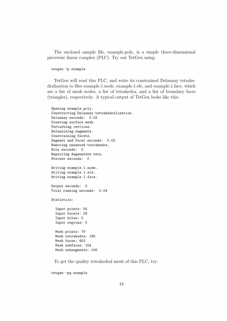
The enclosed sample file, example.poly, is a simple three-dimensionalpiecewise linear complex (PLC). Try out TetGen using:
tetgen -p example
TetGen will read this PLC, and write its constrained Delaunay tetrahe-dralization to files example.1.node, example.1.ele, and example.1.face, whichare a list of mesh nodes, a list of tetrahedra, and a list of boundary faces(triangles), respectively. A typical output of TetGen looks like this:
Opening example.poly.Constructing Delaunay tetrahedralization.Delaunay seconds: 0.02Creating surface mesh.Perturbing vertices.Delaunizing segments.Constraining facets.Segment and facet seconds: 0.02Removing unwanted tetrahedra.Hole seconds: 0Repairing degenerate tets.Steiner seconds: 0
Writing example.1.node.Writing example.1.ele.Writing example.1.face.
Output seconds: 0Total running seconds: 0.04
Statistics:
Input points: 54Input facets: 29Input holes: 0Input regions: 0
Mesh points: 79Mesh tetrahedra: 188Mesh faces: 453Mesh subfaces: 154Mesh subsegments: 106
To get the quality tetrahedral mesh of this PLC, try:
tetgen -pq example
18
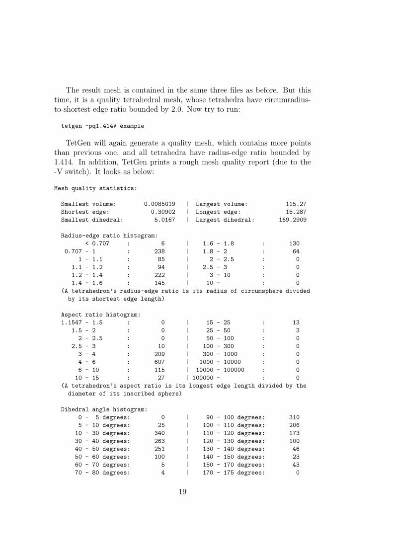
The result mesh is contained in the same three files as before. But thistime, it is a quality tetrahedral mesh, whose tetrahedra have circumradius-to-shortest-edge ratio bounded by 2.0. Now try to run:
tetgen -pq1.414V example
TetGen will again generate a quality mesh, which contains more pointsthan previous one, and all tetrahedra have radius-edge ratio bounded by1.414. In addition, TetGen prints a rough mesh quality report (due to the-V switch). It looks as below:
Mesh quality statistics:
Smallest volume: 0.0085019 | Largest volume: 115.27Shortest edge: 0.30902 | Longest edge: 15.287Smallest dihedral: 5.0167 | Largest dihedral: 169.2909
Radius-edge ratio histogram:< 0.707 : 6 | 1.6 - 1.8 : 130
0.707 - 1 : 238 | 1.8 - 2 : 641 - 1.1 : 85 | 2 - 2.5 : 0
1.1 - 1.2 : 94 | 2.5 - 3 : 01.2 - 1.4 : 222 | 3 - 10 : 01.4 - 1.6 : 145 | 10 - : 0
(A tetrahedron’s radius-edge ratio is its radius of circumsphere dividedby its shortest edge length)
Aspect ratio histogram:1.1547 - 1.5 : 0 | 15 - 25 : 13
1.5 - 2 : 0 | 25 - 50 : 32 - 2.5 : 0 | 50 - 100 : 0
2.5 - 3 : 10 | 100 - 300 : 03 - 4 : 209 | 300 - 1000 : 04 - 6 : 607 | 1000 - 10000 : 06 - 10 : 115 | 10000 - 100000 : 010 - 15 : 27 | 100000 - : 0
(A tetrahedron’s aspect ratio is its longest edge length divided by thediameter of its inscribed sphere)
Dihedral angle histogram:0 - 5 degrees: 0 | 90 - 100 degrees: 3105 - 10 degrees: 25 | 100 - 110 degrees: 20610 - 30 degrees: 340 | 110 - 120 degrees: 17330 - 40 degrees: 263 | 120 - 130 degrees: 10040 - 50 degrees: 251 | 130 - 140 degrees: 4650 - 60 degrees: 100 | 140 - 150 degrees: 2360 - 70 degrees: 5 | 150 - 170 degrees: 4370 - 80 degrees: 4 | 170 - 175 degrees: 0
19
80 - 90 degrees: 79 | 175 - 180 degrees: 0
To compute the Delaunay tetrahedralization and convex hull of the pointset of this PLC, try this:
cp example.poly example.node
tetgen example
The Delaunay tetrahedralization is saved in example.1.node and exam-ple.1.ele. The convex hull is represented by a list of triangles in file exam-ple.1.face.
All these meshes and Delaunay tetrahedralizations can be visualized bythe programs introduced in the next section.
Detailed descriptions of the command line switches and file formats arefound in Section 3 and 4.
2.3 Visualization
2.3.1 TetView
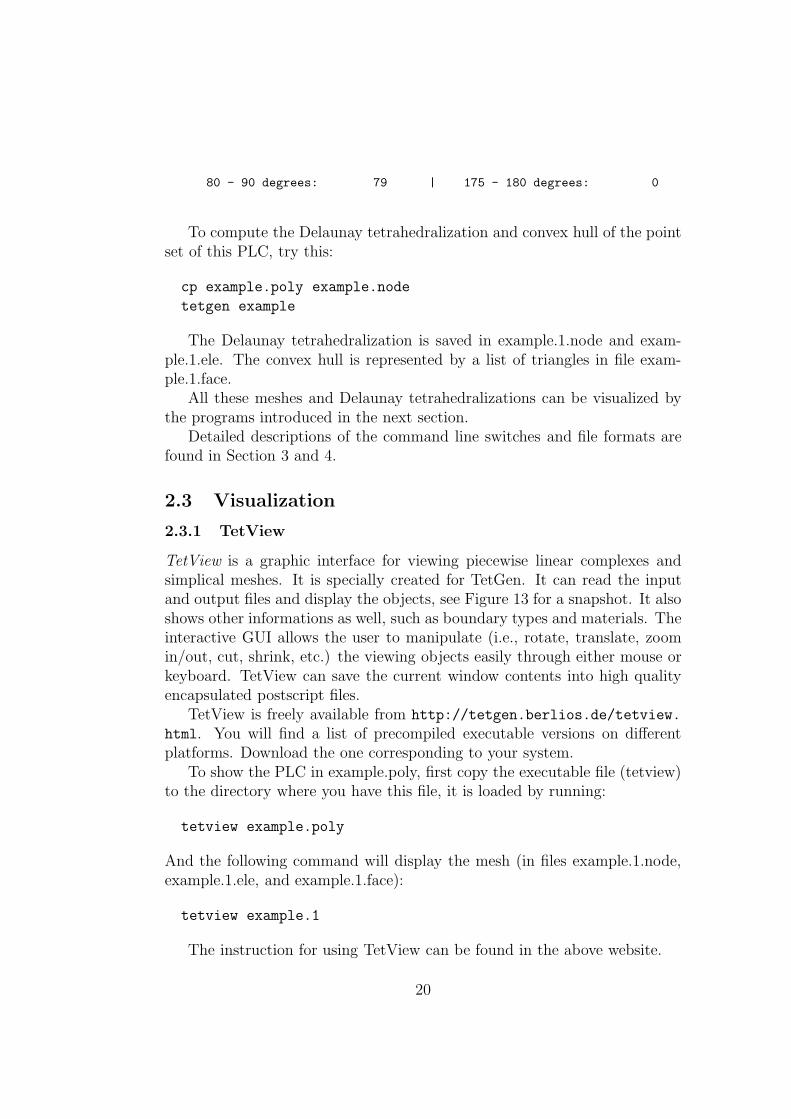
TetView is a graphic interface for viewing piecewise linear complexes andsimplical meshes. It is specially created for TetGen. It can read the inputand output files and display the objects, see Figure 13 for a snapshot. It alsoshows other informations as well, such as boundary types and materials. Theinteractive GUI allows the user to manipulate (i.e., rotate, translate, zoomin/out, cut, shrink, etc.) the viewing objects easily through either mouse orkeyboard. TetView can save the current window contents into high qualityencapsulated postscript files.
TetView is freely available from http://tetgen.berlios.de/tetview.
html. You will find a list of precompiled executable versions on differentplatforms. Download the one corresponding to your system.
To show the PLC in example.poly, first copy the executable file (tetview)to the directory where you have this file, it is loaded by running:
tetview example.poly
And the following command will display the mesh (in files example.1.node,example.1.ele, and example.1.face):
tetview example.1
The instruction for using TetView can be found in the above website.
20
Figure 13: TetView. Left: displays a surface mesh of a car. Right: displaysone of the views of the tetrahedral mesh of the car.
2.3.2 Other Mesh Viewers
Two programs can be alternatively used to view the mesh created by TetGen,both are publicly available and run on most computer systems. They are:
• Medit, a user-friendly mesh viewer, available at http://www-rocq.
inria.fr/gamma/medit.
• Gid, the personal pre- and post-processor, available at http://gid.
cimne.upc.es.
For viewing mesh under Medit, add a ’-g’ switch in the command line.TetGen will additionally output a file example.1.mesh, which can be readand rendered directly by Medit. Try running:
tetgen -pg example.poly
medit example.1
By invoking ’-G’ switch in command line, two additional files exam-ple.1.ele.msh and example.1.face.msh will be output by TetGen, which aretetrahedral mesh and surface mesh, respectively. These files can be loadedinto Gid (version 7.0) using menu “Files” → “Import” → “Gid Mesh...”.
21
3 Using TetGen
This section describes the use of TetGen as a stand alone program. It is in-voked from the command line with a set of switches and an input file name.Switches are used to control the behavior of TetGen and to specify the outputfiles. In correspondence to the different switches, TetGen will generate theDelaunay tetrahedrization, or the boundary constrained (Delaunay) tetra-hedrization, or the quality conforming (Delaunay) mesh.
3.1 Command Line Syntax
The command line syntax to run TetGen is:
tetgen [-pq__a__AriYMS__T__dzjo_fengGOJBNEFICQVvh] input_file
Underscores indicate that numbers may optionally follow certain switches.Do not leave any space between a switch and its numeric parameter. Theseswitches are explained in Section 3.2.
“input file” can be different files depending on the switches you use. Ifno switch is used, it must be a file with extension .node which contains alist of 3D points and the Delaunay tetrahedralization of this point set willbe generated.
If the -p switch is used, “input file” must be one of the following exten-sions: .poly, .smesh, .off, .stl, and .mesh, which contains a piecewise linearcomplex (or a surface mesh) and the boundary constrained (Delaunay) tetra-hedralization of this object will be generated. If the -q switch is used together,the quality conforming tetrahedral mesh will be generated.
If the -r switch is used, a pre-created tetrahedral mesh will be read. youmust supply .node and .ele files, and possibly a .face file, and a .vol file.“input file” can have no file extension. Together with -q switch, the mesh willbe refined with respect to the new quality measure and variant constraints.
File formats are described in Section 4.
3.2 Command Line Switches
Table 1 is an overview of all command line switches and a short descriptionfollows each switch. This information is also available by invoking TetGenwithout any switch and input file.
22
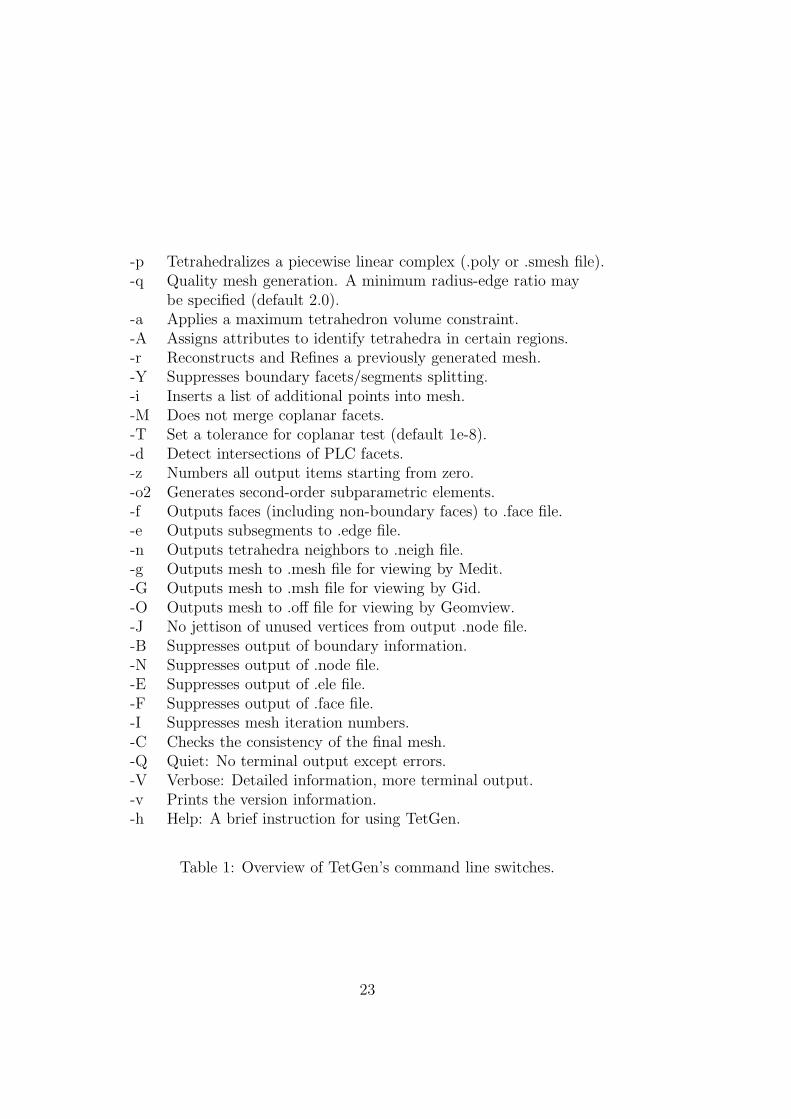
-p Tetrahedralizes a piecewise linear complex (.poly or .smesh file).-q Quality mesh generation. A minimum radius-edge ratio may
be specified (default 2.0).-a Applies a maximum tetrahedron volume constraint.-A Assigns attributes to identify tetrahedra in certain regions.-r Reconstructs and Refines a previously generated mesh.-Y Suppresses boundary facets/segments splitting.-i Inserts a list of additional points into mesh.-M Does not merge coplanar facets.-T Set a tolerance for coplanar test (default 1e-8).-d Detect intersections of PLC facets.-z Numbers all output items starting from zero.-o2 Generates second-order subparametric elements.-f Outputs faces (including non-boundary faces) to .face file.-e Outputs subsegments to .edge file.-n Outputs tetrahedra neighbors to .neigh file.-g Outputs mesh to .mesh file for viewing by Medit.-G Outputs mesh to .msh file for viewing by Gid.-O Outputs mesh to .off file for viewing by Geomview.-J No jettison of unused vertices from output .node file.-B Suppresses output of boundary information.-N Suppresses output of .node file.-E Suppresses output of .ele file.-F Suppresses output of .face file.-I Suppresses mesh iteration numbers.-C Checks the consistency of the final mesh.-Q Quiet: No terminal output except errors.-V Verbose: Detailed information, more terminal output.-v Prints the version information.-h Help: A brief instruction for using TetGen.
Table 1: Overview of TetGen’s command line switches.
23
3.2.1 -p Tetrahedralizes a PLC
The -p switch reads a piecewise linear complex (PLC) stored in file .poly or.smesh and generate a constrained Delaunay tetrahedralization (CDT) of thePLC.
The CDT may have extra vertices added on the input boundary of thePLC. If you want no vertices be added on the boundary, add -Y swicth (seeSection 3.2.8).
If the file extension is not specified, TetGen will look for a file which hasextension .poly or .smesh and use whichever one is available. For example,“tetgen -p xxx” opens the file named xxx.poly (if it doesn’t exist, open thefile xxx.smesh instead) and possibly also opens the file xxx.node; reads inthe whole PLC; and generates a CDT resulting in three files: xxx.1.node,xxx.1.ele, and xxx.1.face.
Other polygonal file formats may be used as input file as well. TetGenrecognizes the file format by its file extension. The following file formats aresupported: .off, .ply, .stl, and .mesh.
In combination with the -q or -a switch, TetGen will generate a qualitytetrahedral mesh of the PLC. -p is not compatible with -r, and should notbe used them together.
3.2.2 -q Quality mesh generation
The -q switch performs quality mesh generation by Shewchuk’s Delaunayrefinement algorithm [27]. It adds vertices to the CDT (used together with-p) or a previously generated mesh (used together with -r) to ensure that notetrahedra have radius-edge ratio greater than 2.0. An alternative minimumradius-edge ratio may be specified after the ’q’. For a too small ratio, e.g.,smaller than 1.0, TetGen may not terminate.
If no input angle or input dihedral angle (of the PLC) is smaller than 60◦,this algorithm is guaranteed to terminate and no tetrahedron has radius-edgeratio greater than 2.0. In practice, one can observe successful terminationfor radius-edge ratios down to
√2 ≈ 1.414 or even smaller.
Here are some examples of using the -q switch. Tests can be executedand compared with the included example file (example.poly):
tetgen -pq example
tetgen -rq1.414 example.1
tetgen -ra0.5 example.2
24
3.2.3 -a Imposes volume constraints
The -a switch imposes a maximum volume constraint on all tetrahedra. Ifa number follows the ’a’, no tetrahedra is generated whose volume is largerthan that number.
If no number is specified and the -r switch is not used, TetGen will readthe region part in file .poly or .smesh. A .poly file or .smesh file can op-tionally contain a volume constraint for each facet-bounded region, therebycontrolling tetrahedra densities in a tetrahedralization of a PLC in a morespecific way.
One can impose both a fixed volume constraint and a varying volume con-straint for some regions by invoking the -a switch twice, once with and oncewithout a number following. Each volume specified may include a decimalpoint.
If no number is specified and the -r switch is used, a .vol file is expected,which contains a separate volume constraint for each tetrahedron. It is usefulfor refining a finite element or finite volume mesh based on a posteriori errorestimates.
3.2.4 -A Assigns region attributes
The -A switch assigns an additional attribute (an integer number) to eachtetrahedron that identifies what facet-bounded region each tetrahedron be-longs to.
Attributes are assigned to regions by the .poly or .smesh file (in the regionsection). If a region is not explicitly marked by the .poly file or .smesh file,tetrahedra in that region are automatically assigned a zero attribute.
If you want TetGen to automatically assign each tetrahedron a regionattribute even the region has no attribute assigned in .poly or .smesh file. Youcan apply ’-A’ switch twice (e.g., ’-AA’). In your output mesh, all tetrahedrain the same region will get a non-zero attribute. Default, attributes arenumbered from 1, 2, 3, and so on. If an attribute has already been used(assigned in .poly or .smesh), it is skipped and the next available attributewill be used.
The -A switch has an effect only when the -p switch is used and the -rswitch is not.
3.2.5 -r Reconstructs/refines a mesh
The -r switch reconstructs a previously generated mesh. The mesh is readfrom a .node and an .ele file, and possibly a .face file. If a .face file exists,it is read and used to constrain subfaces in the mesh, else, TetGen will
25
automatically identify the subfaces, internal subfaces are also identified bycomparing the attributes of two adjacent tetrahedra. Subsegments will beautomatically identified from the existing subfaces. The reconstructed meshis distinguished from its origin with a different iteration number.
For example, “tetgen -r xxx.1” reads the mesh in files xxx.1.node, xxx.1.eleand possibly xxx.1.face and xxx.1.edge if they exist; reconstructs the mesh;outputs it into three files xxx.2.node, xxx.2.ele and xxx.2.face. Now, xxx.2can be used as input in the above command, the result is another mesh savedfiles xxx.3.node, and so on. Mesh iteration numbers allow you to create asequence of successively finer meshes.
One can refine a mesh by combining -r with the -q, -a, and -i switches.Several ways are possible:
• One can impose tighter quality constraints by using the -q with asmaller number, or the -a followed by a smaller volume than the oneused to generate the mesh currently refining.
• One can create a .vol file, which specifies a maximum volume for eachtetrahedra, and use the -a switch (without a number following). Eachtetrahedron’s volume constraint is applied to that tetrahedra.
• One can create a .node file, which contains a list of additional nodesto insert in the mesh. Use the -i switch to inform TetGen that anadditional node list needs to be inserted.
-r should not be used with the -p and -I together.
3.2.6 -i Inserts additional points
The -i switch indicates to insert a list of additional points into a CDT (when-p switch is used) or a previously generated mesh (when -r switch is used).The list of additional file is read from file xxx-a.node, which xxx standsfor the input file name (i.e., xxx.poly or xxx.smesh, or xxx.ele, ...). Thisswitch is useful for refining a finite element or finite volume mesh using a listof user-defined points. Following are some pointers that you may need becareful:
• Points lie out of the mesh domain are ignored by TetGen.
• The mesh may not be constrained Delaunay or conforming Delaunayany more after the insertion of additional points. However, in combi-nation with the -q switch, TetGen will automatically add additionalpoints to ensure the conforming Delaunay property of the mesh.
26
3.2.7 -T Sets a tolerance
The -T switch sets a user-defined tolerance used by many computations ofTetGen, default is 1e − 8.
In principle, the vertices which are used to define a facet of a PLC shouldbe exactly coplanar. But this is very hard to achieve in practice due to theinconsistent nature of the floating-point format used in computers.
TetGen accepts facets which vertices are not exactly but approximatelycoplanar. Four points a, b, c and d are coplanar as long as the ratio v/l3
is smaller than the given tolerance, where v and l are the volume and theaverage edge length of the tetrahedron abcd, respectively.
To choose a proper tolerance according to the input point set will usuallyreduce the number of adding points and improve the mesh quality.
3.2.8 -Y Prohibit Steiner Points on Boundary
The -Y switch suppresses the creation of Steiner points on the exterior bound-ary. Interior Steiner points may still be created.
This switch is useful when the mesh boundary must be preserved so thatit conforms to some adjacent mesh.
Specify this switch twice (‘-YY’) to prevent all boundary splitting, in-cluding interior boundaries.
You can use -Y together with -q switch (to improve the quality of themesh), TetGen will try, but the resulting mesh may contain tetrahedra ofpoor quality. However, it works well if all the boundaries are previouslysubdivided into well shaped and closely spaced patches.
3.2.9 Other Switches
-I The -I switch does not use the iteration numbers, it suppresses the outputof .node file, so your input file won’t be overwritten. It cannot be used withthe -r switch, because that would overwrite your input .ele file. It shouldn’tbe used with the -q, -a, -s, or -t switch if one is using a .node file for input,because no .node file is written, so there is no record of any added Steinerpoints.
-z The -z switch numbers all output items starting from zero. This switchis useful in case of calling TetGen from another program.
-o2 TetGen generates meshes with quadratic elements if the -o2 switch isspecified. Quadratic elements have ten nodes per element, rather than four.
27
The six extra nodes of a tetrahedron fall at the midpoints of its six edges.Refer to Section 4.1.4 (.ele file format) to find out how the extra nodes arelocally related to a tetrahedron.
-C The -C switch indicates TetGen to check the consistency of the mesh onfinish. If it is specified twice, i.e., ’-CC’, TetGen also checks constrained De-launay (for the -p switch) or conforming Delaunay (for -q, -a, or -i) propertyof the mesh.
-V The -V switch gives detailed information about what TetGen is doing.More ’V’s are increasing the amount of detail.
Specifically, ’-V’ gives information on algorithmic progress and more de-tailed statistics including a rough mesh quality report. To get the statisticsfor an existing mesh, run TetGen on that mesh with the ’-rNEP’ switches toread the mesh and print the statistics without writing any files.
’-VV’ gives more details on the algorithms, and slow down the execution.While ’-VVV’ is only useful for debugging.
3.3 Command Line Examples
TetGen generates Delaunay, constrained tetrahedralizations, and quality meshesaccording to different command line switches and input files. This sectionprovides several examples of each task.
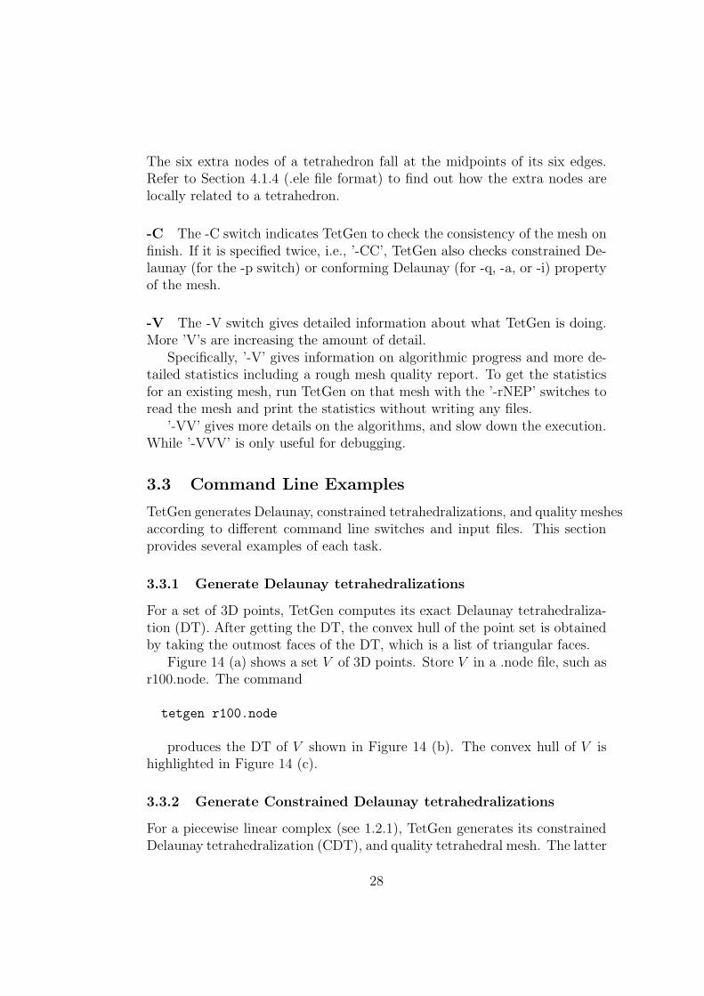
3.3.1 Generate Delaunay tetrahedralizations
For a set of 3D points, TetGen computes its exact Delaunay tetrahedraliza-tion (DT). After getting the DT, the convex hull of the point set is obtainedby taking the outmost faces of the DT, which is a list of triangular faces.
Figure 14 (a) shows a set V of 3D points. Store V in a .node file, such asr100.node. The command
tetgen r100.node
produces the DT of V shown in Figure 14 (b). The convex hull of V ishighlighted in Figure 14 (c).
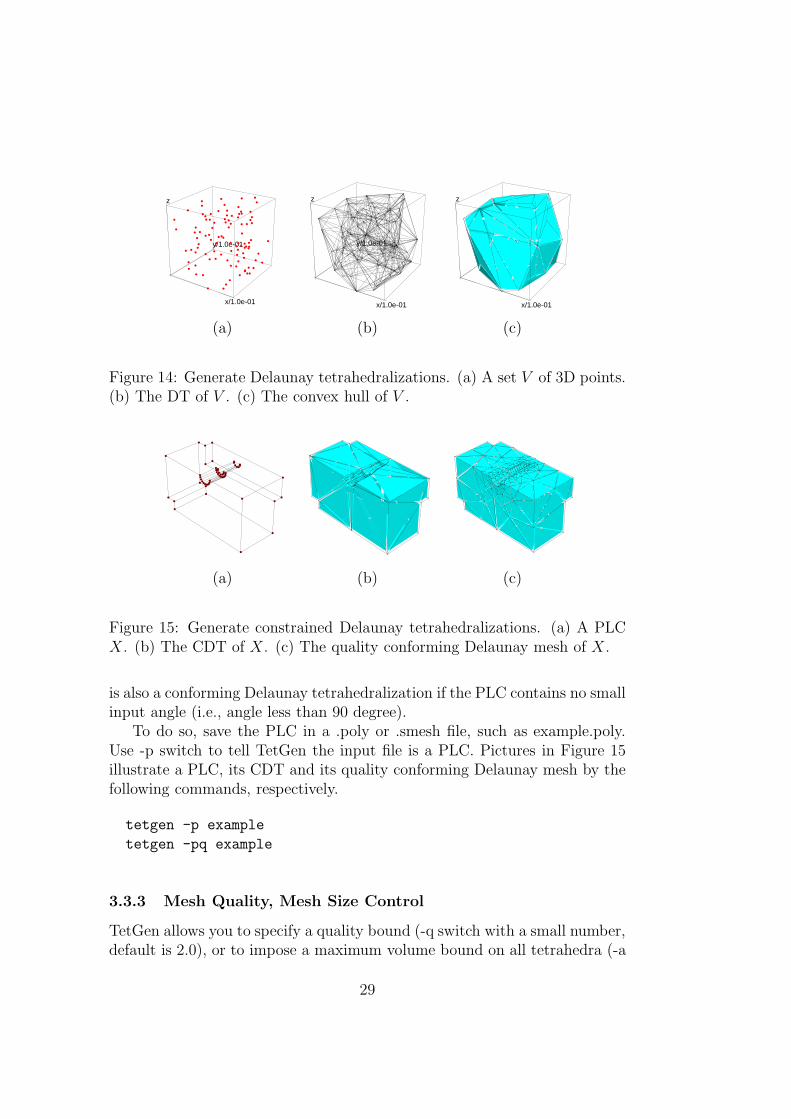
3.3.2 Generate Constrained Delaunay tetrahedralizations
For a piecewise linear complex (see 1.2.1), TetGen generates its constrainedDelaunay tetrahedralization (CDT), and quality tetrahedral mesh. The latter
28
y/1.0e-01
z
x/1.0e-01
y/1.0e-01
z
x/1.0e-01
y/1.0e-01
z
x/1.0e-01
(a) (b) (c)
Figure 14: Generate Delaunay tetrahedralizations. (a) A set V of 3D points.(b) The DT of V . (c) The convex hull of V .
(a) (b) (c)
Figure 15: Generate constrained Delaunay tetrahedralizations. (a) A PLCX. (b) The CDT of X. (c) The quality conforming Delaunay mesh of X.
is also a conforming Delaunay tetrahedralization if the PLC contains no smallinput angle (i.e., angle less than 90 degree).
To do so, save the PLC in a .poly or .smesh file, such as example.poly.Use -p switch to tell TetGen the input file is a PLC. Pictures in Figure 15illustrate a PLC, its CDT and its quality conforming Delaunay mesh by thefollowing commands, respectively.
tetgen -p example
tetgen -pq example
3.3.3 Mesh Quality, Mesh Size Control
TetGen allows you to specify a quality bound (-q switch with a small number,default is 2.0), or to impose a maximum volume bound on all tetrahedra (-a
29
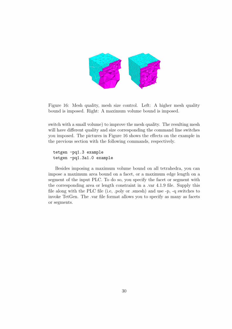
Figure 16: Mesh quality, mesh size control. Left: A higher mesh qualitybound is imposed. Right: A maximum volume bound is imposed.
switch with a small volume) to improve the mesh quality. The resulting meshwill have different quality and size corresponding the command line switchesyou imposed. The pictures in Figure 16 shows the effects on the example inthe previous section with the following commands, respectively.
tetgen -pq1.3 example
tetgen -pq1.3a1.0 example
Besides imposing a maximum volume bound on all tetrahedra, you canimpose a maximum area bound on a facet, or a maximum edge length on asegment of the input PLC. To do so, you specify the facet or segment withthe corresponding area or length constraint in a .var 4.1.9 file. Supply thisfile along with the PLC file (i.e, .poly or .smesh) and use -p, -q switches toinvoke TetGen. The .var file format allows you to specify as many as facetsor segments.
30
.node input/output a list of nodes.
.poly input a PLC.
.smesh input/output a simple PLC.
.ele input/output a list of tetrahedra.
.face input/output a list of triangular faces.
.edge output a list of boundary edges.
.vol input a list of maximum volumes.
.var input a list of variant constraints.
.neigh output a list of neighbors.
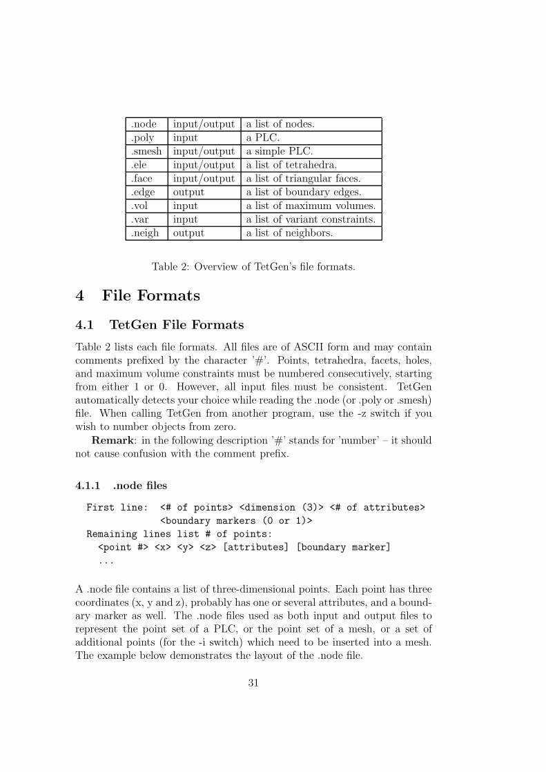
Table 2: Overview of TetGen’s file formats.
4 File Formats
4.1 TetGen File Formats
Table 2 lists each file formats. All files are of ASCII form and may containcomments prefixed by the character ’#’. Points, tetrahedra, facets, holes,and maximum volume constraints must be numbered consecutively, startingfrom either 1 or 0. However, all input files must be consistent. TetGenautomatically detects your choice while reading the .node (or .poly or .smesh)file. When calling TetGen from another program, use the -z switch if youwish to number objects from zero.
Remark: in the following description ’#’ stands for ’number’ – it shouldnot cause confusion with the comment prefix.
4.1.1 .node files
First line: <# of points> <dimension (3)> <# of attributes>
<boundary markers (0 or 1)>
Remaining lines list # of points:
<point #> <x> <y> <z> [attributes] [boundary marker]
...
A .node file contains a list of three-dimensional points. Each point has threecoordinates (x, y and z), probably has one or several attributes, and a bound-ary marker as well. The .node files used as both input and output files torepresent the point set of a PLC, or the point set of a mesh, or a set ofadditional points (for the -i switch) which need to be inserted into a mesh.The example below demonstrates the layout of the .node file.
31
# Node count, 3 dim, no attribute, no boundary marker8 3 0 0# Node index, node coordinates1 0.0 0.0 0.02 1.0 0.0 0.03 1.0 1.0 0.04 0.0 1.0 0.05 0.0 0.0 1.06 1.0 0.0 1.07 1.0 1.0 1.08 0.0 1.0 1.0
The attributes, which are typically floating-point values of physical quan-tities (such as mass or conductivity) associated with the points, are copiedunchanged to the output mesh. If -p switch is used, each new Steiner pointinserted on segments of the mesh has attributes assigned to it by linear in-terpolation. Furthermore, if -q, -a, or -i is selected, each new point added tothe mesh to improve mesh quality has attributes zero.
If the fourth entry of the first line is ’1’, the last column of the remainderof the file is assumed to contain boundary markers. Boundary markers areused to identify boundary points (points resting on PLC facets). The .nodefile produced by TetGen contains boundary markers in the last column unlessthey are suppressed by the -B switch. The boundary marker associated witheach point in an output .node file is chosen as follows:
• If a point is assigned a nonzero boundary marker in the input file, thenit is assigned the same marker in the output .node file.
• Otherwise, if the node lies on a PLC facet with a nonzero boundarymarker, then the node is assigned the same marker that facet has. If thenode lies on several such facets, one of the markers is chosen arbitrarily.
• Otherwise, if the node occurs on a boundary of the mesh, then the nodeis assigned the marker (1).
• Otherwise, the point is assigned the marker zero (0).
TetGen can determine which points are on the boundary, input with theboundary marker zero (or use no markers at all) will result in output withboundary marker (1) for all points on the boundary.
4.1.2 .poly files
A .poly file represents a piecewise linear complex (PLC) as well as someadditional information. Although there is no restriction on facets of PLCs,
32
TetGen requires that the mesh region represented by a PLC should be com-pletely facet-bounded, i.e. it is waterproof.
The .poly file format consists of four parts, which are a list of points, alist of facets, a list of (volume) hole points, and a list of region attributes,respectively. The first three parts are mandatory, but the fourth part isoptional.
The four parts are described below. In the end of this section, a .poly filewhich describes a 1 × 1 × 1 cube is provided.
Part 1 - node list
First line: <# of points> <dimension (3)> <# of attributes>
<boundary markers (0 or 1)>
Remaining lines list # of points:
<point #> <x> <y> <z> [attributes] [boundary marker]
...
Part 1 lists all the points, and is identical to the format of .node files. <# ofpoints> may be set to zero to indicate that the points are listed in a separate.node file.
Part 2 - facet list
One line: <# of facets> <boundary markers (0 or 1)>
Following lines list # of facets:
<facet #>
...
Each facet is indeed a planar straight line graph (PSLG), it is a polygonalregion which may contain segments, single points and holes. A list of polygonsconsist of a facet. Each polygon has n corners, n ≥ 1. It can be degenerate,i.e., n = 1 or n = 2 represents a single point or a segment, respectively. Theformat of a facet is:
One line: <# of polygons> [# of holes] [boundary marker]
Following lines list # of polygons:
<# of corners> <corner 1> <corner 2> ... <corner #>
...
Following lines list # of holes:
<hole #> <x> <y> <z>
...
33
Each polygon is specified by giving the number of corners, followed by thelist of ordered indices of those corners. It doesn’t matter which order (coun-terclockwise or clockwise) you choose to list the indices. Each line of indicesshould not be arbitrarily long because the maximum characters per line readby TetGen is 1024. The list can be broken into several lines.
A hole in a facet (don’t confuse with the volume hole below) is specifiedby identifying a point inside the hole. The list of hole points (consecutively)follows the list of polygons.
If the boundary markers is ’1’, TetGen will produce an additional bound-ary marker for each face in .face file (in the last column of each record). Youcan prevent boundary markers from being written into .face file by using the-B switch.
Boundary markers of facets are tags used mainly to identify which facesof the tetrahedralization are associated with which PLC facet, hence identifywhich faces occur on a boundary of the tetrahedralization. A common use isto determine where different boundary condition types should be applied toa mesh.
Part 3 - (volume) hole list
One line: <# of holes>
Following lines list # of holes:
<hole #> <x> <y> <z>
...
Holes in the volume are specified by identifying a point inside each hole. Afterthe constrained Delaunay tetrahedrization is formed, TetGen creates holesby removing tetrahedra. Thus exactly is the reason why TetGen requires aclosed boundary of the PLCs. In case of non-closed PLC facets the wholetetrahedrization will be ’eaten’ away. If two tetrahedra abutting a subfaceare removed, the subface itself is also vanished. Hole points have to be placedinside a region, else the rounding error determines which side of the facet isbeing transformed into the hole.
Part 4 - region attributes list
One line: <# of region>
Following lines list # of region attributes:
<region #> <x> <y> <z> <region number> <region attribute>
...
34
1
7
4 3
2
5 6
8
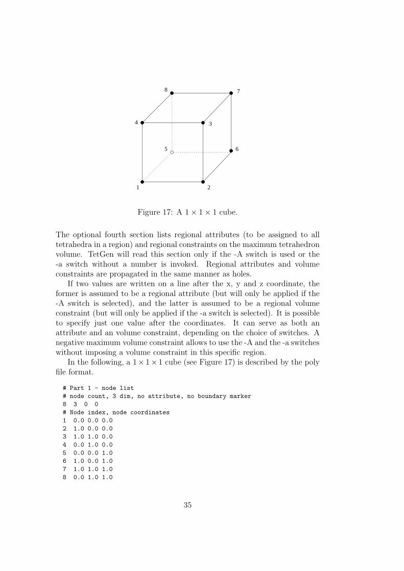
Figure 17: A 1 × 1 × 1 cube.
The optional fourth section lists regional attributes (to be assigned to alltetrahedra in a region) and regional constraints on the maximum tetrahedronvolume. TetGen will read this section only if the -A switch is used or the-a switch without a number is invoked. Regional attributes and volumeconstraints are propagated in the same manner as holes.
If two values are written on a line after the x, y and z coordinate, theformer is assumed to be a regional attribute (but will only be applied if the-A switch is selected), and the latter is assumed to be a regional volumeconstraint (but will only be applied if the -a switch is selected). It is possibleto specify just one value after the coordinates. It can serve as both anattribute and an volume constraint, depending on the choice of switches. Anegative maximum volume constraint allows to use the -A and the -a switcheswithout imposing a volume constraint in this specific region.
In the following, a 1× 1× 1 cube (see Figure 17) is described by the polyfile format.
# Part 1 - node list# node count, 3 dim, no attribute, no boundary marker8 3 0 0# Node index, node coordinates1 0.0 0.0 0.02 1.0 0.0 0.03 1.0 1.0 0.04 0.0 1.0 0.05 0.0 0.0 1.06 1.0 0.0 1.07 1.0 1.0 1.08 0.0 1.0 1.0
35
# Part 2 - facet list# facet count, no boundary marker6 0# facets1 # 1 polygon, no hole, no boundary marker4 1 2 3 4 # front14 5 6 7 8 # back14 1 2 6 5 # bottom14 2 3 7 6 # right14 3 4 8 7 # top14 4 1 5 8 # left
# Part 3 - hole list0 # no hole
# Part 4 - region list0 # no region
4.1.3 .smesh files
A .smesh file represents a PLC of special type - surface meshes. The .smeshfile format is a simplified version of the .poly format, that each facet only hasexactly one polygon, no holes, no segment and point inside. It is less flexiblethan the .poly file format but is much simpler and useful when the surfacemesh is created by other programs.
The same as .poly file format, the .smesh file format consists of fourparts, which are points, facets, holes and regions, respectively. Only the partdescribing facets is different from the .poly format. It is described below.
Part 2 - facet list
One line: <# of facets> <boundary markers (0 or 1)>
Following lines list # of facets:
<# of corners> <corner 1> ... <corner #> [boundary marker]
...
Each facet consists of exactly one polygon. The corner list of each polygoncan be distributed over a number of lines. The optional boundary marker ofeach facet is given at the end of the corner list.
The following example demonstrates the layout of facet part of the unitcubde (Figure 17).
36
1
2
3
4
56
7
8
9
10
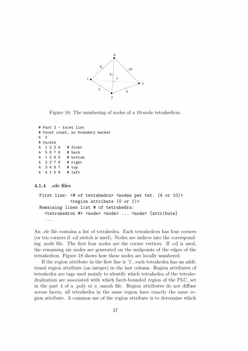
Figure 18: The numbering of nodes of a 10-node tetrahedron.
# Part 2 - facet list# facet count, no boundary marker6 0# facets4 1 2 3 4 # front4 5 6 7 8 # back4 1 2 6 5 # bottom4 2 3 7 6 # right4 3 4 8 7 # top4 4 1 5 8 # left
4.1.4 .ele files
First line: <# of tetrahedra> <nodes per tet. (4 or 10)>
<region attribute (0 or 1)>
Remaining lines list # of tetrahedra:
<tetrahedron #> <node> <node> ... <node> [attribute]
...
An .ele file contains a list of tetrahedra. Each tetrahedron has four corners(or ten corners if -o2 switch is used). Nodes are indices into the correspond-ing .node file. The first four nodes are the corner vertices. If -o2 is used,the remaining six nodes are generated on the midpoints of the edges of thetetrahedron. Figure 18 shows how these nodes are locally numbered.
If the region attribute in the first line is ’1’, each tetrahedra has an addi-tional region attribute (an integer) in the last column. Region attributes oftetrahedra are tags used mainly to identify which tetrahedra of the tetrahe-dralization are associated with which facet-bounded region of the PLC, setin the part 4 of a .poly or a .smesh file. Region attributes do not diffuseacross facets, all tetrahedra in the same region have exactly the same re-gion attribute. A common use of the region attribute is to determine which
37
material a tetrahedron has.The .ele file is the default output file of TetGen if it generated a mesh or
tetrahedralization. However, it can be omitted by -E switch. If -r switch isused, TetGen reads a .ele file and reconstructs a tetrahedral mesh from it.
The following example illustrates the layout of the .ele file.
154 4 01 4 107 3 502 4 108 3 1073 9 97 95 944 4 107 50 935 56 1 50 476 94 98 97 957 97 9 95 558 52 55 5 51...
4.1.5 .face files
First line: <# of faces> <boundary marker (0 or 1)>
Remaining lines list # of faces:
<face #> <node> <node> <node> [boundary marker]
...
A .face file contains a list of triangular faces, which may be boundary faces (if-p or -r switch is used), or convex hull faces. Each face has three corners andpossibly has a boundary marker. Nodes are indices into the corresponding.node file.
After generating a mesh or Delaunay tetrahedralization, TetGen defaultoutputs the boundary faces or the convex hull into a .face file. However, thisfile can be omitted by -F switch. If -r switch is used, TetGen can also readthe .face file for identifying boundary faces in a reconstructed mesh. Theoptional column of Boundary markers is suppressed by the -B switch.
If the boundary marker in the first line is ’1’, each face has an addi-tional boundary marker (an integer) in the last column. Boundary markersof facets are defined in the .poly or the .smesh files. They are tags usedmainly to identify which faces of the tetrahedralization are associated withwhich PLC facet, and to identify which faces occur on a boundary of thetetrahedralization. A common use is to determine where different boundaryconditions.
4.1.6 .edge files
First line: <# of edges>
38
Remaining lines list # of edges:
<edge #> <endpoint> <endpoint>
...
A .edge file contains a list of edges, which are (sub)segments of a PLC. Eachedge has two endpoints which are indices into the corresponding .node file.It is part of TetGen’s output when -e switch is used.
4.1.7 .vol files
First line: <# of tetrahedra>
Remaining lines list # of maximum volumes:
<tetrahedron #> <maximum volume>
...
A .vol file associates with each tetrahedron a maximum volume which is usedfor mesh refinement. It is read by TetGen in case the -r switch is used.
As with other file formats, every tetrahedron must be represented, andthey must be numbered consecutively. A tetrahedron may be left uncon-strained by assigning it a negative maximum volume.
4.1.8 .var files
One line: <# of facet constraints>
Remaining lines list # of facet constraints:
<constraint #> <boundary marker> <maximum area>
...
One line: <# of segment constraints>
Remaining lines list # of segment constraints:
<constraint #> <point1> <point2> <maximum length>
...
A .var file allows you to specify variant constraints on facets and segments.Like the maximum volume bound set to a region, each facet can have amaximum area bound. On the output, no subface of the facet has arealarger that bound. Likewise, each segment can have a maximum lengthbound, hence, the subsegments of that segment will no longer than it.
Facet constraint is set on facet by specifying the boundary marker whichis the integer assigned that facet in the corresponding .poly or .smesh file.Segment constraint is set to a segment by specifying two indices of endpointsof the segment.
The following example illustrates the layout of a .var file. It can be usedtogether with the included file “example.poly”.
39
.off input/output Geomview’s polyhedral file format.
.ply input Polyhedral file format.
.stl input Stereolithography format.
.mesh input/output Medit’s surface mesh file format.
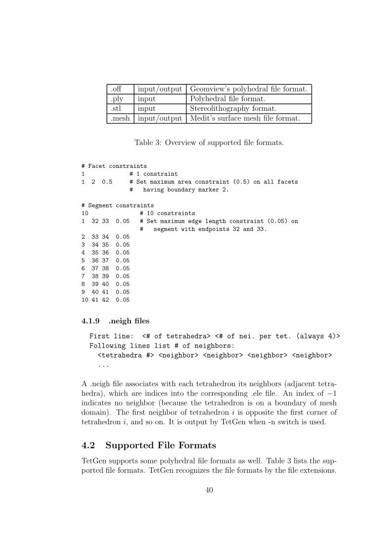
Table 3: Overview of supported file formats.
# Facet constraints1 # 1 constraint1 2 0.5 # Set maximum area constraint (0.5) on all facets
# having boundary marker 2.
# Segment constraints10 # 10 constraints1 32 33 0.05 # Set maximum edge length constraint (0.05) on
# segment with endpoints 32 and 33.2 33 34 0.053 34 35 0.054 35 36 0.055 36 37 0.056 37 38 0.057 38 39 0.058 39 40 0.059 40 41 0.0510 41 42 0.05
4.1.9 .neigh files
First line: <# of tetrahedra> <# of nei. per tet. (always 4)>
Following lines list # of neighbors:
<tetrahedra #> <neighbor> <neighbor> <neighbor> <neighbor>
...
A .neigh file associates with each tetrahedron its neighbors (adjacent tetra-hedra), which are indices into the corresponding .ele file. An index of −1indicates no neighbor (because the tetrahedron is on a boundary of meshdomain). The first neighbor of tetrahedron i is opposite the first corner oftetrahedron i, and so on. It is output by TetGen when -n switch is used.
4.2 Supported File Formats
TetGen supports some polyhedral file formats as well. Table 3 lists the sup-ported file formats. TetGen recognizes the file formats by the file extensions.
40
4.2.1 .off files
.off is the one of the file formats of Geomview http://www.geomview.org
- an interactive 3D viewing program for Unix/Linux. It represents collec-tions of planar polygons with possibly shared vertices, a convenient way todescribe polyhedra. The polygons may be concave but there’s no provisionfor polygons containing holes.
The description of .off file format can be found elsewhere in the internet.Below is a simple description of this file format.
OFF numVertices numFaces numEdges
x y z
x y z
... numVertices like above
NVertices v1 v2 v3 ... vN
MVertices v1 v2 v3 ... vM
... numFaces like above
Note that vertices are numbered starting at 0 (not starting at 1), andthat numEdges will always be zero.
4.2.2 .ply files
The .ply file format is a simple object description that was designed as aconvenient format for researchers who work with polygonal models. Earlyversions of this file format were used at Stanford University and at UNCChapel Hill.
A description as well as examples, codes of the PLY file format can befound at http://astronomy.swin.edu.au/~pbourke/geomformats/ply.
4.2.3 .stl files
The .stl or stereolithography format is an ASCII or binary file used in man-ufacturing. It is a list of the triangular surfaces that describe a computergenerated solid model. This is the standard input for most rapid prototypingmachines.
The description of .stl file format can be found elsewhere on the web. Anelaborated description can be found at http://www.sdsc.edu/tmf/Stl-specs/stl.html. Below is an example.
solid
...
41
facet normal 0.00 0.00 1.00
outer loop
vertex 2.00 2.00 0.00
vertex -1.00 1.00 0.00
vertex 0.00 -1.00 0.00
endloop
endfacet
...
endsolid
4.2.4 .mesh files
.mesh is the file formats of Medit - an interactive 3D mesh viewing pro-gram http://www.ann.jussieu.fr/~frey/logiciels/medit.html. Thisfile format is described in the documentation of Medit.
A repository of free 3D models in this file format are available at INRIA’sFree 3D Meshes Download http://www-rocq1.inria.fr/gamma.
4.3 File Format Examples
This section provides two examples. They are designed to support interactivelearning. The topics are description of the PLCs using TetGen’s .poly fileformat and constructing different quality meshes through the command lineswitches.
4.3.1 A PLC with Two Boundary Markers
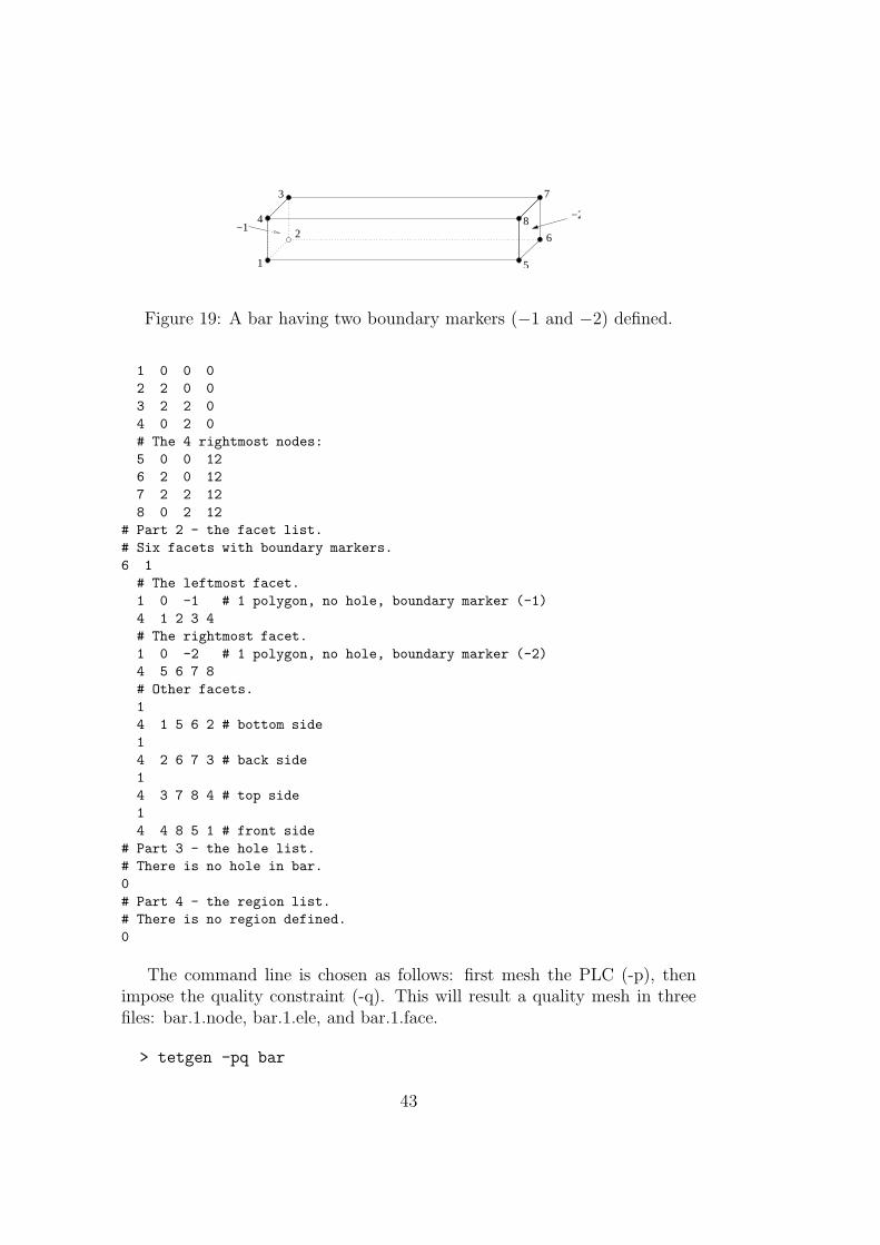
Figure 19 shows the geometry of a rectangular bar. This bar consists ofeight nodes and six facets (which are all rectangles). In addition, thereare two boundary markers (−1 and −2) associated to the leftmost facetand the rightmost facet, respectively. This simple model has its physicalmeaning. It can be seen as a typical heat transfer problem. The task isto compute the temperature diffusion in the bar, in which the flow of heatmoves from hot side to cold side. The two boundary markers can representtwo different boundary conditions, one has high temperature and the otherhas low temperature. Here is the input file “bar.poly” describing the bar:
# Part 1 - the node list.# A bar with 8 nodes in 3D, no attributes, no boundary marker.8 3 0 0# The 4 leftmost nodes:
42
1
4
3
5
6
8
7
−2
2−1
Figure 19: A bar having two boundary markers (−1 and −2) defined.
1 0 0 02 2 0 03 2 2 04 0 2 0# The 4 rightmost nodes:5 0 0 126 2 0 127 2 2 128 0 2 12
# Part 2 - the facet list.# Six facets with boundary markers.6 1# The leftmost facet.1 0 -1 # 1 polygon, no hole, boundary marker (-1)4 1 2 3 4# The rightmost facet.1 0 -2 # 1 polygon, no hole, boundary marker (-2)4 5 6 7 8# Other facets.14 1 5 6 2 # bottom side14 2 6 7 3 # back side14 3 7 8 4 # top side14 4 8 5 1 # front side
# Part 3 - the hole list.# There is no hole in bar.0# Part 4 - the region list.# There is no region defined.0
The command line is chosen as follows: first mesh the PLC (-p), thenimpose the quality constraint (-q). This will result a quality mesh in threefiles: bar.1.node, bar.1.ele, and bar.1.face.
> tetgen -pq bar
43
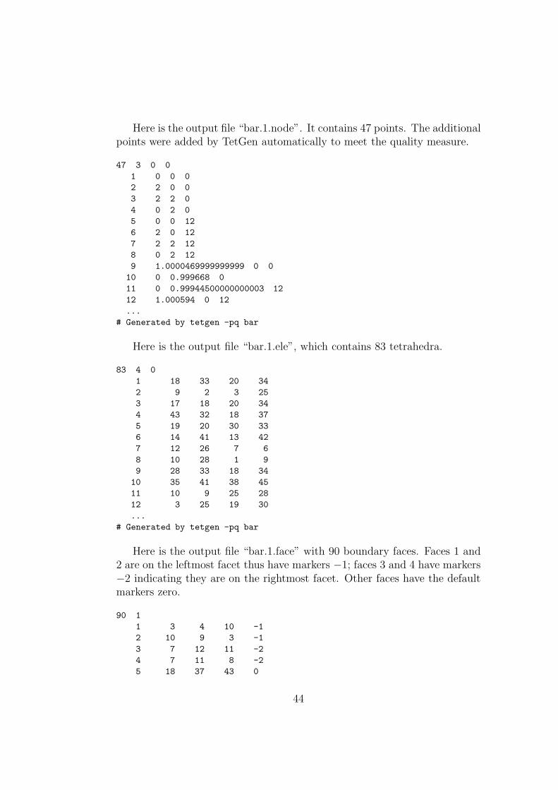
Here is the output file “bar.1.node”. It contains 47 points. The additionalpoints were added by TetGen automatically to meet the quality measure.
47 3 0 01 0 0 02 2 0 03 2 2 04 0 2 05 0 0 126 2 0 127 2 2 128 0 2 129 1.0000469999999999 0 010 0 0.999668 011 0 0.99944500000000003 1212 1.000594 0 12...
# Generated by tetgen -pq bar
Here is the output file “bar.1.ele”, which contains 83 tetrahedra.
83 4 01 18 33 20 342 9 2 3 253 17 18 20 344 43 32 18 375 19 20 30 336 14 41 13 427 12 26 7 68 10 28 1 99 28 33 18 34
10 35 41 38 4511 10 9 25 2812 3 25 19 30...
# Generated by tetgen -pq bar
Here is the output file “bar.1.face” with 90 boundary faces. Faces 1 and2 are on the leftmost facet thus have markers −1; faces 3 and 4 have markers−2 indicating they are on the rightmost facet. Other faces have the defaultmarkers zero.
90 11 3 4 10 -12 10 9 3 -13 7 12 11 -24 7 11 8 -25 18 37 43 0
44
1
4
3
5
6
8
7
−2
2
9
10
11
12−1
−20−10
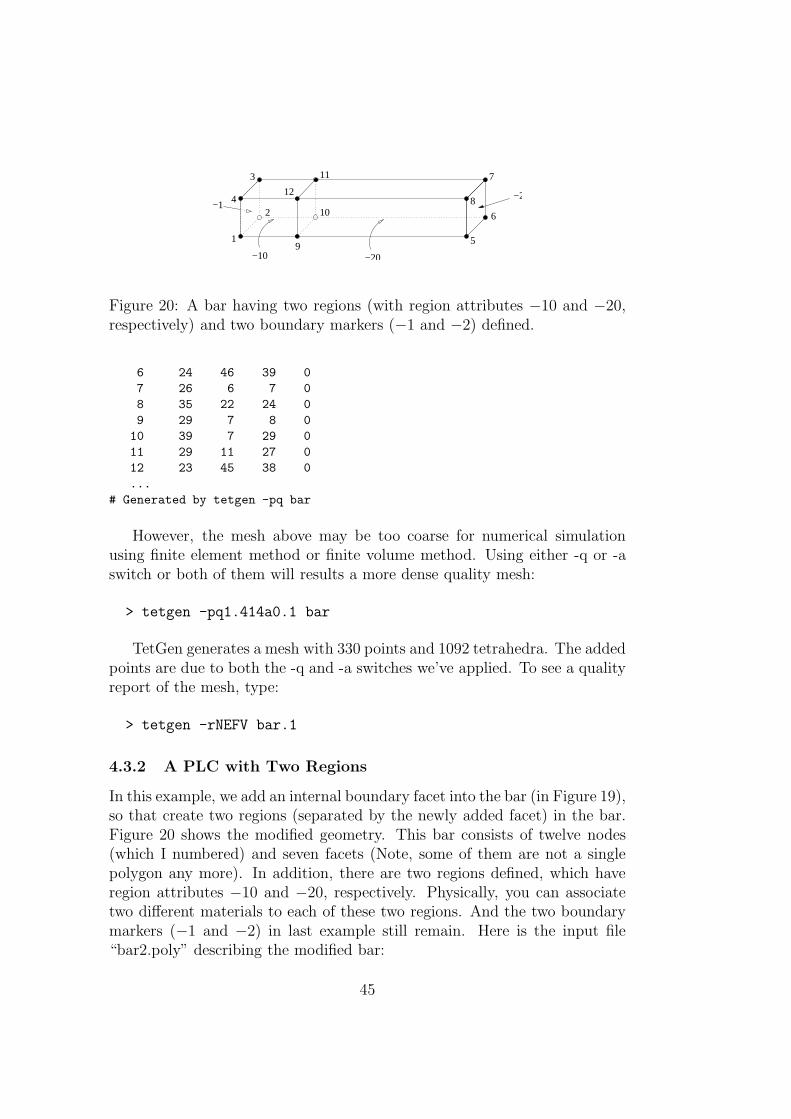
Figure 20: A bar having two regions (with region attributes −10 and −20,respectively) and two boundary markers (−1 and −2) defined.
6 24 46 39 07 26 6 7 08 35 22 24 09 29 7 8 010 39 7 29 011 29 11 27 012 23 45 38 0...
# Generated by tetgen -pq bar
However, the mesh above may be too coarse for numerical simulationusing finite element method or finite volume method. Using either -q or -aswitch or both of them will results a more dense quality mesh:
> tetgen -pq1.414a0.1 bar
TetGen generates a mesh with 330 points and 1092 tetrahedra. The addedpoints are due to both the -q and -a switches we’ve applied. To see a qualityreport of the mesh, type:
> tetgen -rNEFV bar.1
4.3.2 A PLC with Two Regions
In this example, we add an internal boundary facet into the bar (in Figure 19),so that create two regions (separated by the newly added facet) in the bar.Figure 20 shows the modified geometry. This bar consists of twelve nodes(which I numbered) and seven facets (Note, some of them are not a singlepolygon any more). In addition, there are two regions defined, which haveregion attributes −10 and −20, respectively. Physically, you can associatetwo different materials to each of these two regions. And the two boundarymarkers (−1 and −2) in last example still remain. Here is the input file“bar2.poly” describing the modified bar:
45
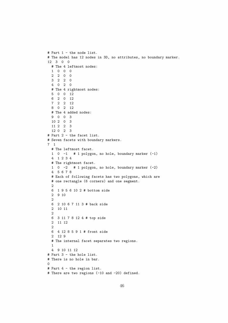
# Part 1 - the node list.# The model has 12 nodes in 3D, no attributes, no boundary marker.12 3 0 0# The 4 leftmost nodes:1 0 0 02 2 0 03 2 2 04 0 2 0# The 4 rightmost nodes:5 0 0 126 2 0 127 2 2 128 0 2 12# The 4 added nodes:9 0 0 310 2 0 311 2 2 312 0 2 3
# Part 2 - the facet list.# Seven facets with boundary markers.7 1# The leftmost facet.1 0 -1 # 1 polygon, no hole, boundary marker (-1)4 1 2 3 4# The rightmost facet.1 0 -2 # 1 polygon, no hole, boundary marker (-2)4 5 6 7 8# Each of following facets has two polygons, which are# one rectangle (6 corners) and one segment.26 1 9 5 6 10 2 # bottom side2 9 1026 2 10 6 7 11 3 # back side2 10 1126 3 11 7 8 12 4 # top side2 11 1226 4 12 8 5 9 1 # front side2 12 9# The internal facet separates two regions.14 9 10 11 12
# Part 3 - the hole list.# There is no hole in bar.0# Part 4 - the region list.# There are two regions (-10 and -20) defined.
46
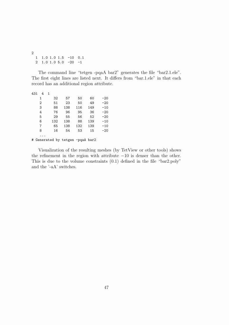
21 1.0 1.0 1.5 -10 0.12 1.0 1.0 5.0 -20 -1
The command line “tetgen -pqaA bar2” generates the file “bar2.1.ele”.The first eight lines are listed next. It differs from “bar.1.ele” in that eachrecord has an additional region attribute.
431 4 11 32 57 50 60 -202 51 23 50 49 -203 88 138 116 149 -104 76 96 95 36 -205 29 55 56 52 -206 132 138 88 139 -107 65 138 132 139 -108 16 54 53 15 -20...
# Generated by tetgen -pqaA bar2
Visualization of the resulting meshes (by TetView or other tools) showsthe refinement in the region with attribute −10 is denser than the other.This is due to the volume constraints (0.1) defined in the file “bar2.poly”and the ’-aA’ switches.
47
5 Calling TetGen from Another Program
In addition to being used as a stand alone program, TetGen can be calledfrom another program. The TetGen library provides functions and datastructures. One of the advantages of using the TetGen library is that it canbe repeatedly called by other programs without the overhead of reading andwriting files. The feature is very useful for applications like adaptive FEMand FVM methods.
This section gives the necessary instructions for using the TetGen library.Examples are included for better understanding. Users are supposed to beable to use TetGen, i.e., know its command line switches and the input andoutput file formats. Furthermore, Section 2 contains the instruction of howto compile TetGen into a library.
5.1 The Header File
All programs calling TetGen must include the header file “tetgen.h”.
#include "tetgen.h"
It includes all data types and function declarations of the TetGen library.More specifically, it defines the function “tetrahedralize()” and the data type“tetgenio”, which are provided for users to call TetGen with all its function-alities. They are described in Section 5.2 and Section 5.3, respectively.
5.2 The Calling Convention
The function “tetrahedralize()” is declared as follows:
void tetrahedralize(char *switches, tetgenio *in, tetgenio *out)
The parameter “switches” is a string containing the command line switchesfor this call. In this string, no initial dash ’-’ is required. The ‘Q’ (quiet)switch is recommended in the final code. The ‘I’ (no iteration numbers), ‘g’(.mesh file output), and ’G’ (.msh file output) switches have no effect.
The parameters “in” and “out”, which are two pointers pointing to ob-jects of “tetgenio”, describing the input and the output. “in” and “out” maynever be NULL.
48
5.3 The “tetgenio” Data Type
The “tetgenio” structure is used to pass data into and out of the tetrahe-dralize() procedure. It replaces the input and output files of TetGen by acollection of arrays, which are used to store points, tetrahedra, markers, andso forth. It is declared as a C++ class including data fields and functions.The data fields of “tetgenio”:
int firstnumber; // 0 or 1, default 0.int mesh_dim; // must be 3.
REAL *pointlist;REAL *pointattributelist;REAL *addpointlist;int *pointmarkerlist;int numberofpoints;int numberofpointattributes;int numberofaddpoints;
int *tetrahedronlist;REAL *tetrahedronattributelist;REAL *tetrahedronvolumelist;int *neighborlist;int numberoftetrahedra;int numberofcorners;int numberoftetrahedronattributes;
facet *facetlist;int *facetmarkerlist;int numberoffacets;
REAL *holelist;int numberofholes;
REAL *regionlist;int numberofregions;
REAL *facetconstraintlist;int numberoffacetconstraints;
REAL *segmentconstraintlist;int numberofsegmentconstraints;
int *trifacelist;int *trifacemarkerlist;int numberoftrifaces;
int *edgelist;int *edgemarkerlist;
49
int numberofedges;
5.4 Description of Arrays
In all cases, the first item in any array is stored starting at index [0]. However,that item is item number “firstnumber” (0 or 1) unless the ‘z’ switch is used,in which case it is item number ‘0’. Following is the description of arrays.
pointlist An array of point coordinates. The first point’s x coordinate isat index [0], its y coordinate at index [1], and its z coordinate at index [2],followed by the coordinates of the remaining points. Each point occupiesthree REALs.
pointattributelist An array of point attributes. Each point’s attributesoccupy “numberofpointattributes” REALs.
pointmarkerlist An array of point markers; one int per point.
addpointlist An array of additional point coordinates, which will be readand inserted into the mesh when the -i switch is used.. The same structureas “pointlist”, each point occupies three REALs.
tetrahedronlist An array of tetrahedron corners. The first tetrahedron’sfirst corner is at index [0], followed by its other three corners, followed byany other nodes if the ’-o2’ switch is used. Each tetrahedron occupies “num-berofcorners” (4 or 10) ints.
tetrahedronattributelist An array of tetrahedron attributes. Each tetra-hedron’s attributes occupy “numberoftetrahedronattributes” REALs.
tetrahedronvolumelist An array of tetrahedron volume constraints; oneREAL per tetrahedron. Input only.
neighborlist An array of tetrahedron neighbors; four ints per tetrahedron.Output only.
facetlist An array of PLC facets. Each facet is an object of type “facet”(see Section 5.4.2).
50
facetmarkerlist An array of facet markers; one int per facet.
holelist An array of holes. The first hole’s x, y and z coordinates are atindices [0], [1] and [2], followed by the remaining holes. Three REALs perhole.
regionlist An array of regional attributes and volume constraints. Thefirst constraints’ x, y and z coordinates are at indices [0], [1] and [2], followedby the regional attribute at index [3], followed by the maximum volume atindex [4], followed by the remaining volume constraints. Five REALs pervolume constraint. Each regional attribute is used only if the ‘A’ switchis used, and each volume constraint is used only if the ‘a’ switch (with nonumber following) is used, but omitting one of these switches does not changethe memory layout.
facetconstraintlist An array of facet maximum area constraints. TwoREALs per constraint. The first one is the facet marker (cast the type tointeger), the second is its maximum area bound. Note the ’facetconstraintlist’is used only for the ’q’ switch.
segmentconstraintlist An array of segment length constraints. Two RE-ALs per constraint. The first one is the index (pointing into ’pointlist’) ofthe node, the second is its maximum length bound. Note the ’segmentcon-straintlist’ is used only for the ’q’ switch.
trifacelist An array of triangular faces. The first face’s corners are atindices [0], [1] and [2], followed by the remaining faces. Three ints per face.
trifacemarkerlist An array of face markers; one int per face.
edgelist An array of segment endpoints. The first segment’s endpoints areat indices [0] and [1], followed by the remaining segments. Two ints persegment.
edgemarkerlist An array of segment markers; one int per segment.
5.4.1 Memory Management
Two routines defined in tetgenio are used for memory initialization and clean-ing. They are:
51
void initialize();void deinitialize();
“initialize()” initializes all fields, that is, all pointers to arrays are initial-ized to NULL, and other variables are initialized to zero except the variable’numberofcorners’, which is 4 (a tetrahedron has 4 nodes). Initialization isimplicitly called by the constructor of tetgenio. For an example, the followingline creates an object of tetgenio named “io”, all fields of “io” are initialized:
tetgenio io;
The next step is to allocate memory for each array which will be used.In C++ the memory allocation and deletion can be done by the “new” and“delete” operators. Another pair of functions (preferred by C programmers)are “malloc()” and “free()”. Whatever you use, you must stick with one ofthese two pairs, e.g., ’new’/’delete’ and ’malloc’/’free’ can not be mixed. Forexample, the following line allocates memory for “io.pointlist”:
io.pointlist = new REAL[io.numberofpoints * 3];
“deinitialize” frees the memory allocated in objects of tetgenio by using’delete’. It is automatically called on deletion of the tetgenio objects. If thememory was allocated by using the function “malloc()”, the user is responsi-ble to free it. After having freed all memory, one call of “initialize()” disablesthe automatic memory deletion.
To reuse an object is possible: first call “deinitialize()”, then call “initial-ize()” before the next use.
5.4.2 The “facet” Data Structure
The “facet” data structure defined in tetgenio can be used to represent anyfacet of a PLC. However, to preserve the flexibility, to use is not straightfor-ward.
The structure of facet shown below consists of a list of polygons and alist of hole points.
typedef struct {polygon *polygonlist;int numberofpolygons;REAL *holelist;int numberofholes;
} facet;
A polygon is again an object of type “polygon”’. It consists of a list ofcorner points (“vertexlist”). The structure is shown below.
52
typedef struct {int *vertexlist;int numberofvertices;
} polygon;
In fact, the structure of facet is a direct translation of the facet format ina .poly file, described in Section 3.2.2. The front facet of Figure 20 serves anexample for setting a PLC facet into an object of facet. It has two polygons,one has six vertices, and the other is a segment, no holes, the ASCII data is:
26 4 12 8 5 9 1 # front side2 12 9
The following C++ code does the translation. Assume the object oftetgenio is “io” and has already be created.
tetgenio::facet *f; // Define a pointer of facet.tetgenio::polygon *p; // Define a pointer of polygon.
// All indices start from 1.io.firstnumber = 1;
...
// Use ’f’ to point to a facet of ’facetlist’.f = &io.facetlist[i];// Initialize the fields of this facet.// There are two polygons, no holes.f->numberofpolygons = 2;// Allocate memory for polygons.f->polygonlist = new tetgenio::polygon[2];f->numberofholes = 0;f->holelist = NULL;
// Set the data of the first polygon into facet.p = &f->polygonlist[0];p->numberofvertices = 6;// Allocate memory for vertices.p->vertexlist = new int[6];p->vertexlist[0] = 4;p->vertexlist[1] = 12;p->vertexlist[2] = 8;p->vertexlist[3] = 5;p->vertexlist[4] = 9;p->vertexlist[5] = 1;
// Set the data of the second polygon into facet.
53

p = &f->polygonlist[1];p->numberofvertices = 2;p->vertexlist = new int[2]; // Alloc. memory for vertices.p->vertexlist[0] = 12;p->vertexlist[1] = 9;
5.5 An Example
This section gives an example of how to call TetGen from another programby using the “tetgenio” data structure and the function “tetrahedralize()”.The example in Section 4.3.1 (Figure 19) is used again.
The complete C++ source code is given below. It is also available in Tet-Gen’s website:http://tetgen.berlios.de/files/tetcall.cxx. The codeillustrates the following basic steps:
• at first creates an input object “in” of tetgenio containing the data ofthe bar;
• then it calls function “tetrahedralize()” to create a quality mesh of thebar with output in “out”.
In addition, It outputs the PLC in the object “in” into two files (barin.nodeand barin.poly), and outputs the mesh in the object “out” into three files(barout.node, barout.ele, and barout.face). These files can be visualized byTetView.
This example can be compiled into an executable program.
• Compile TetGen into a library named “libtet.a” (see Section 2.1 forcompiling);
• Save the file “tetcall.cxx” into the same directory in which you havethe files “tetgen.h” and “libtet.a”;
• Compile it using the following command:
g++ -o test tetcall.cxx -L./ -ltet
which will result an executable file “test”.
The complete source codes are given below:
54
#include "tetgen.h" // Defined tetgenio, tetrahedralize().
int main(int argc, char *argv[]){tetgenio in, out;tetgenio::facet *f;tetgenio::polygon *p;int i;
// All indices start from 1.in.firstnumber = 1;
in.numberofpoints = 8;in.pointlist = new REAL[in.numberofpoints * 3];in.pointlist[0] = 0; // node 1.in.pointlist[1] = 0;in.pointlist[2] = 0;in.pointlist[3] = 2; // node 2.in.pointlist[4] = 0;in.pointlist[5] = 0;in.pointlist[6] = 2; // node 3.in.pointlist[7] = 2;in.pointlist[8] = 0;in.pointlist[9] = 0; // node 4.in.pointlist[10] = 2;in.pointlist[11] = 0;// Set node 5, 6, 7, 8.for (i = 4; i < 8; i++) {in.pointlist[i * 3] = in.pointlist[(i - 4) * 3];in.pointlist[i * 3 + 1] = in.pointlist[(i - 4) * 3 + 1];in.pointlist[i * 3 + 2] = 12;
}
in.numberoffacets = 6;in.facetlist = new tetgenio::facet[in.numberoffacets];in.facetmarkerlist = new int[in.numberoffacets];
// Facet 1. The leftmost facet.f = &in.facetlist[0];f->numberofpolygons = 1;f->polygonlist = new tetgenio::polygon[f->numberofpolygons];f->numberofholes = 0;f->holelist = NULL;p = &f->polygonlist[0];p->numberofvertices = 4;p->vertexlist = new int[p->numberofvertices];p->vertexlist[0] = 1;p->vertexlist[1] = 2;p->vertexlist[2] = 3;
55
p->vertexlist[3] = 4;
// Facet 2. The rightmost facet.f = &in.facetlist[1];f->numberofpolygons = 1;f->polygonlist = new tetgenio::polygon[f->numberofpolygons];f->numberofholes = 0;f->holelist = NULL;p = &f->polygonlist[0];p->numberofvertices = 4;p->vertexlist = new int[p->numberofvertices];p->vertexlist[0] = 5;p->vertexlist[1] = 6;p->vertexlist[2] = 7;p->vertexlist[3] = 8;
// Facet 3. The bottom facet.f = &in.facetlist[2];f->numberofpolygons = 1;f->polygonlist = new tetgenio::polygon[f->numberofpolygons];f->numberofholes = 0;f->holelist = NULL;p = &f->polygonlist[0];p->numberofvertices = 4;p->vertexlist = new int[p->numberofvertices];p->vertexlist[0] = 1;p->vertexlist[1] = 5;p->vertexlist[2] = 6;p->vertexlist[3] = 2;
// Facet 4. The back facet.f = &in.facetlist[3];f->numberofpolygons = 1;f->polygonlist = new tetgenio::polygon[f->numberofpolygons];f->numberofholes = 0;f->holelist = NULL;p = &f->polygonlist[0];p->numberofvertices = 4;p->vertexlist = new int[p->numberofvertices];p->vertexlist[0] = 2;p->vertexlist[1] = 6;p->vertexlist[2] = 7;p->vertexlist[3] = 3;
// Facet 5. The top facet.f = &in.facetlist[4];f->numberofpolygons = 1;f->polygonlist = new tetgenio::polygon[f->numberofpolygons];f->numberofholes = 0;
56
f->holelist = NULL;p = &f->polygonlist[0];p->numberofvertices = 4;p->vertexlist = new int[p->numberofvertices];p->vertexlist[0] = 3;p->vertexlist[1] = 7;p->vertexlist[2] = 8;p->vertexlist[3] = 4;
// Facet 6. The front facet.f = &in.facetlist[5];f->numberofpolygons = 1;f->polygonlist = new tetgenio::polygon[f->numberofpolygons];f->numberofholes = 0;f->holelist = NULL;p = &f->polygonlist[0];p->numberofvertices = 4;p->vertexlist = new int[p->numberofvertices];p->vertexlist[0] = 4;p->vertexlist[1] = 8;p->vertexlist[2] = 5;p->vertexlist[3] = 1;
// Set ’in.facetmarkerlist’
in.facetmarkerlist[0] = -1;in.facetmarkerlist[1] = -2;in.facetmarkerlist[2] = 0;in.facetmarkerlist[3] = 0;in.facetmarkerlist[4] = 0;in.facetmarkerlist[5] = 0;
// Output the PLC to files ’barin.node’ and ’barin.poly’.in.save_nodes("barin");in.save_poly("barin");
// Tetrahedralize the PLC. Switches are chosen to read a PLC (p),// do quality mesh generation (q) with a specified quality bound// (1.414), and apply a maximum volume constraint (a0.1).
tetrahedralize("pq1.414a0.1", &in, &out);
// Output mesh to files ’barout.node’, ’barout.ele’ and ’barout.face’.out.save_nodes("barout");out.save_elements("barout");out.save_faces("barout");
return 0;}
57
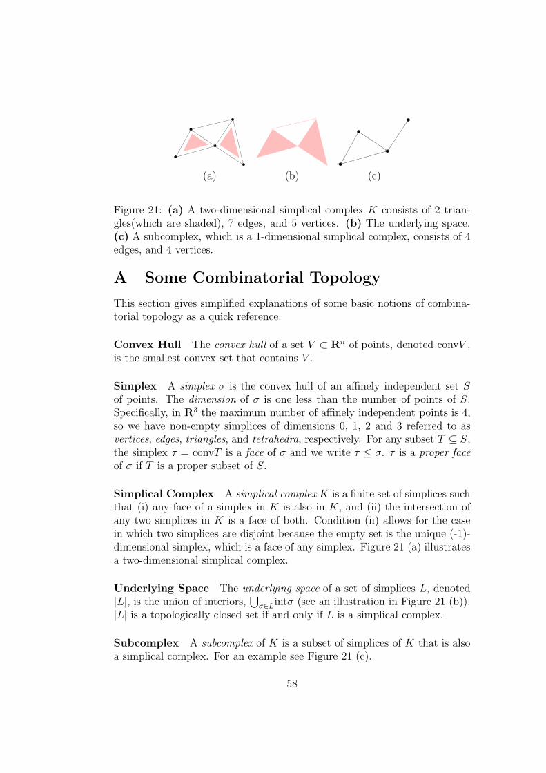
(a) (b) (c)
Figure 21: (a) A two-dimensional simplical complex K consists of 2 trian-gles(which are shaded), 7 edges, and 5 vertices. (b) The underlying space.(c) A subcomplex, which is a 1-dimensional simplical complex, consists of 4edges, and 4 vertices.
A Some Combinatorial Topology
This section gives simplified explanations of some basic notions of combina-torial topology as a quick reference.
Convex Hull The convex hull of a set V ⊂ Rn of points, denoted convV ,is the smallest convex set that contains V .
Simplex A simplex σ is the convex hull of an affinely independent set Sof points. The dimension of σ is one less than the number of points of S.Specifically, in R3 the maximum number of affinely independent points is 4,so we have non-empty simplices of dimensions 0, 1, 2 and 3 referred to asvertices, edges, triangles, and tetrahedra, respectively. For any subset T ⊆ S,the simplex τ = convT is a face of σ and we write τ ≤ σ. τ is a proper faceof σ if T is a proper subset of S.
Simplical Complex A simplical complex K is a finite set of simplices suchthat (i) any face of a simplex in K is also in K, and (ii) the intersection ofany two simplices in K is a face of both. Condition (ii) allows for the casein which two simplices are disjoint because the empty set is the unique (-1)-dimensional simplex, which is a face of any simplex. Figure 21 (a) illustratesa two-dimensional simplical complex.
Underlying Space The underlying space of a set of simplices L, denoted|L|, is the union of interiors,
⋃σ∈Lintσ (see an illustration in Figure 21 (b)).
|L| is a topologically closed set if and only if L is a simplical complex.
Subcomplex A subcomplex of K is a subset of simplices of K that is alsoa simplical complex. For an example see Figure 21 (c).
58
References
[1] Delaunay Boris N., Sur la Sphere Vide. Izvestia Akademia Nauk SSSR,VII Seria, Otdelenie Matematicheskii i Estestvennyka Nauk 7:793-800,1934.
[2] Schonhardt E., Uber die Zerlegung von Dreieckspolyedern in Tetraeder.Mathematische Annalen 98:309–312, 1928
[3] Bagemihl F., On Indecomposable Polyhedra. American MathematicalMonthly 55: 411–413, 1948
[4] Chazelle B. Convex Partition of Polyhedra: A lower Bound and Worst-case Optimal Algorithm. SIAM Journal on Computing 13(3): 488–507,1984
[5] Lawson C. L., Software for C1 surface interpolation. In MathematicalSoftware III, Academic Press, New York, 161-194, 1977.
[6] Chew P. L., Guaranteed-Quality Delaunay Meshing in 3D. Proc. 13thAnnu. ACM Sympos. Comput. Geom., 391–393, 1997.
[7] Chew L. P., Constrained Delaunay Triangulation. Algorithmica 4(1):97-108, 1989.
[8] Chew L. P., Guaranteed-Quality Triangular Meshes. Technical ReportTR-89-983, Department of Computer Science, Cornell University, 1989.
[9] Chew L. P., Guaranteed-Quality Mesh Generation for Curved Surfaces.Proceedings of the 9th Annual Symposium on Computational Geome-try, pages 274-280. ACM May, 1993.
[10] Joe B., Construction of Three-dimensional Delaunay Triangulationsfrom local transformations. Computer Aided Geometric Design 8: 123-142, 1991.
[11] Shephard M. S. and Georges M. K., Three-dimensional Mesh Genera-tion by Finite Octree Technique. J. Numer. Methods in Engineer. 32:709–749, 1991.
[12] Lo S. H., Volume Discretization into Tetrahedra - II. 3D Triangulationby Advancing Front Approach. Computers and Structures, 39: 501–511,1991.
59
[13] Clarkson, K. L., Mehlhorn K., and Seidel R., Four Results on Random-ized Incremental Constructions. In Symposium on Theoretical Aspectsof Computer Science, 1992.
[14] Ruppert J. and Seidel R., On the difficulty of triangulating three-dimensional non-convex polyhedra. Discrete & Computational Geom-etry 7: 227-254, 1992.
[15] Ruppert J. A Delaunay Refinement Algorithm for Quality Mesh Gen-eration. Journal of Algorithms 18(3):548-585, May 1995.
[16] Rajan V. T., Optimality of the Delaunay Triangulation in Rd. DiscreteComput. Geom. 12: 189-202, 1994.
[17] Miller G. L., Talmor D., Teng S.-H., Walkington N., and Wang H., ADelaunay Based Numerical Method for Three Dimensions: Generation,Formulation, and Partition. Proceeding of 27th Annual ACM Sympo-sium on the Theory of Computing, pages 683-692, May 1995.
[18] Barber, C.B., Dobkin, D.P., and Huhdanpaa, H.T., The Quickhullalgorithm for convex hulls. ACM Trans. on Mathematical Software,22(4):469-483, Dec 1996, http://www.qhull.org.
[19] Miller G. L., Talmor D., Teng S.-H., Walkington N., and Wang H.,Control Volume Meshes Using Sphere Packing: Generation, Refinementand Coarsening. Proceeding of 5th International Meshing Roundtable,pages 47-61, 1996.
[20] Ziegler G. M., Lectures on Polytopes. Volume 152 of Graduate Texts inMathematics. Springer Verlag, New York, 1995.
[21] Lohner R., Progress in Grid Generation via the Advancing Front Tech-nique. Engineering with Computers, 12: 186–210, 1996
[22] Edelsbrunner H. and Shah N. R., Incremental Topological FlippingWorks for Regular Triangulations. Algorithmica 15: 223-241, 1996.
[23] Edelsbrunner H., Geometry and Topology for Mesh Generation. Cam-bridge Monographs on Applied and Computational Mathematics; ISBN0-521-79309-2, 2001.
[24] Edelsbrunner H., Guoy D., An Experimental Study of Sliver Exudation.Engineering With Computers, 18: 229–240, 2002
60
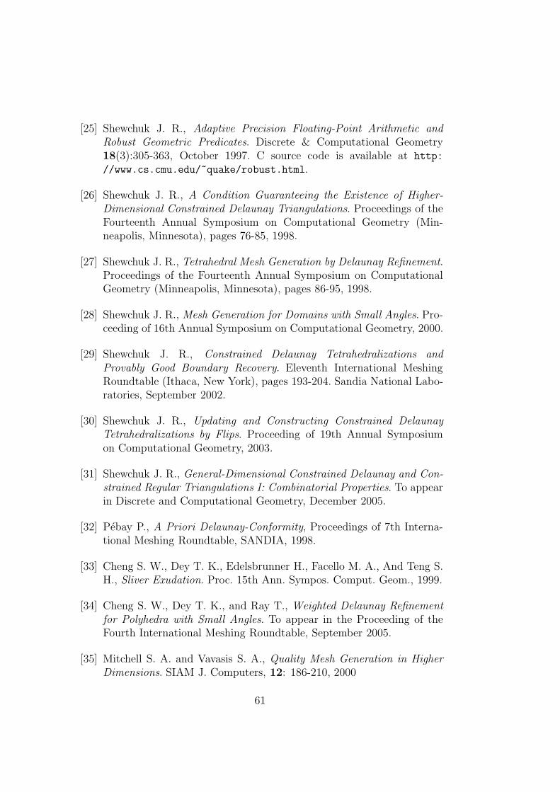
[25] Shewchuk J. R., Adaptive Precision Floating-Point Arithmetic andRobust Geometric Predicates. Discrete & Computational Geometry18(3):305-363, October 1997. C source code is available at http:
//www.cs.cmu.edu/~quake/robust.html.
[26] Shewchuk J. R., A Condition Guaranteeing the Existence of Higher-Dimensional Constrained Delaunay Triangulations. Proceedings of theFourteenth Annual Symposium on Computational Geometry (Min-neapolis, Minnesota), pages 76-85, 1998.
[27] Shewchuk J. R., Tetrahedral Mesh Generation by Delaunay Refinement.Proceedings of the Fourteenth Annual Symposium on ComputationalGeometry (Minneapolis, Minnesota), pages 86-95, 1998.
[28] Shewchuk J. R., Mesh Generation for Domains with Small Angles. Pro-ceeding of 16th Annual Symposium on Computational Geometry, 2000.
[29] Shewchuk J. R., Constrained Delaunay Tetrahedralizations andProvably Good Boundary Recovery. Eleventh International MeshingRoundtable (Ithaca, New York), pages 193-204. Sandia National Labo-ratories, September 2002.
[30] Shewchuk J. R., Updating and Constructing Constrained DelaunayTetrahedralizations by Flips. Proceeding of 19th Annual Symposiumon Computational Geometry, 2003.
[31] Shewchuk J. R., General-Dimensional Constrained Delaunay and Con-strained Regular Triangulations I: Combinatorial Properties. To appearin Discrete and Computational Geometry, December 2005.
[32] Pebay P., A Priori Delaunay-Conformity, Proceedings of 7th Interna-tional Meshing Roundtable, SANDIA, 1998.
[33] Cheng S. W., Dey T. K., Edelsbrunner H., Facello M. A., And Teng S.H., Sliver Exudation. Proc. 15th Ann. Sympos. Comput. Geom., 1999.
[34] Cheng S. W., Dey T. K., and Ray T., Weighted Delaunay Refinementfor Polyhedra with Small Angles. To appear in the Proceeding of theFourth International Meshing Roundtable, September 2005.
[35] Mitchell S. A. and Vavasis S. A., Quality Mesh Generation in HigherDimensions. SIAM J. Computers, 12: 186-210, 2000
61
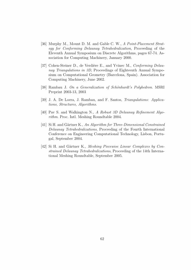
[36] Murphy M., Mount D. M. and Gable C. W., A Point-Placement Strat-egy for Conforming Delaunay Tetrahedralization, Proceeding of theEleventh Annual Symposium on Discrete Algorithms, pages 67-74. As-sociation for Computing Machinery, January 2000.
[37] Cohen-Steiner D., de Verdiere E., and Yvinec M., Conforming Delau-nay Triangulations in 3D, Proceedings of Eighteenth Annual Sympo-sium on Computational Geometry (Barcelona, Spain). Association forComputing Machinery, June 2002.
[38] Rambau J. On a Generalization of Schonhardt’s Polyhedron. MSRIPreprint 2003-13, 2003
[39] J. A. De Loera, J. Rambau, and F. Santos, Triangulations: Applica-tions, Structures, Algorithms.
[40] Pav S. and Walkington N., A Robust 3D Delaunay Refinement Algo-rithm. Proc. Intl. Meshing Roundtable 2004.
[41] Si H. and Gartner K., An Algorithm for Three-Dimensional ConstrainedDelaunay Tetrahedralizations, Proceeding of the Fourth InternationalConference on Engineering Computational Technology, Lisbon, Portu-gal, September 2004.
[42] Si H. and Gartner K., Meshing Piecewise Linear Complexes by Con-strained Delaunay Tetrahedralizations, Proceeding of the 14th Interna-tional Meshing Roundtable, September 2005.
62