Automation, or Russian Roulette? - IDEALS @ Illinois: IDEALS Home

THE UNIVERSITY
OF ILLINOIS
LIBRARY

m

Digitized by the Internet Archive
in 2013
http://archive.org/details/testsofoxyacetylOObrow
TESTS OF OXYACETYLENE WELDS
BY
ELMER ARTHUR BROWNGEORGE WILLIAM WATTS
THESIS
FOR THE
DEGREE OF BACHELOR OF SCIENCE
IN MECHANICAL ENGINEERING
IN
THE COLLEGE OF ENGINEERING
OF THE
UNIVERSITY OF ILLINOIS
1915


IW5
UNIVERSITY OF ILLINOIS
May 31
,
191 5
THIS IS TO CERTIFY THAT THE THESIS PREPARED UNDER MY SUPERVISION BY
Elmer.. Arthur....Br o wn....and George v'ill iaai Fa.tt.s
ENTITLED Tests of Oaryacetylene Welde
IS APPROVED BY ME AS FULFILLING THIS PART OF THE REQUIREMENTS FOR THE
DEGREE OF ...Bachelor .. of Science ...in :.:ech an ic al ..
rng i ne ering
APPROVED:
Instructor in Charge
HEAD OF DEPARTMENT OF
ci

STRENGTHS OF OXYXXETYLENE WELDS IN CAST IROM .
I. Introduction .
This pert of the thesis was undertaken to supplement the
work previously done on the subject by H. H. Constant at the
University of Illinois , 1912. It is deemed needless to present
the results oi the work exready done as such data was compiled
by the above named experimenter. 3?he immediate purpose of the
thesis was to investigate the efficiency oi oxyecetyiene wexds
in cast iron subjected to tension. Tension tests were usedalways
because cast iron practically iaixs in tension, and it wouxd
be practically impossible to maxe a compression test show anything
since the wexd would be required merely to keep the v, tided parts
from slipping which would require very little force. Efforte
were made to keep ail conditions as to quality oi iron, welding
rod and flux used constant.
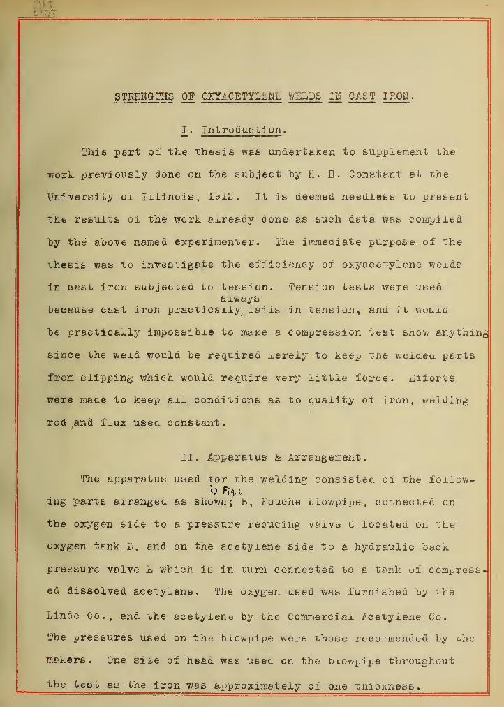
II. Apparatus & Arrangement.
The apparatus used lor the welding consisted 01 the follow-|Q Fig. I.
ing parts arranged as shown; B , i'ouche blowpipe, connected on
the oxygen side to a pressure reducing vaxve C located on the
oxygen tank D, and on the acetylene side to a hydraulic back
pressure valve £ which is in turn connected to a tank of compress-
ed dissolved ecetyxene. The oxygen used was furnished by the
Linde Co., and the acetylene by the Commereiax Acetylene Co.
The pressures used on the biowpj pe were those recommended by the
makers. One si2,e of head was used on the Dxowpipe throughout
the test as the iron was approximately oi one tnickness.


AHRMGEMEHT OF APPARATUS AC DESCRIBED IH SECTIOH II. PAGE 1.

-c-
Ho records were kept a& to the amount b oi gases and wexding rod
used.
Ill . Specimens .
8The specimens tested were oi good grade 01 gray cast iron
poured uy the University foundry. The specimen^ used were made
at two pourings, care ueing taken that the specimen© taken at
each pouring were taken from the same tep. The specimens, as
shown by the sketch, were oi the eye bar type. The eye bar type
was used on account o± the
difficulties encountered
with any other method of
gripping that would give 1 —- J 4"1—j
—
1
a uniformity of stress over the entire section. A large eye
was used inorder to keep the specimen from breaking in the eye,
it having oeen found that this was the point of greatest weak-
ness oi such sections. The gripping was aone by drixling holesinserting pins
in the eyes, and ^supported by straps which in turn were support-other pins resting on
ed byAthe crossheadt of the testing machine. The stretch of
the straps coupxed with the roxl ol the pins permitted the puil
to oe transmitted axiaily to the Specimen. The specimens were
broKen in tension, weldea, and broken again. Shis was aone in
order that actual conditions be duplicated as nearxy as possiule.
In some cases where the specimen Droke outside oi the weld ,"uhe
piece was welded and jjuiled a second time. Ail tests were run
on an Olsen LOO, 000 pound testing machine. The cross sectionaj.
area of the specimen was taken both before end afier welding,
and in the cases where the specimen broke outside of ihe weld


the area was taken again. The ultimate load was noted in each
case. No perce^table elongation was noted.
IV . Welding .
Before any v/exds were made on the test specimens , the
operators made a number 01 wexds on other pieces 01 cast iron
in order to become familiar with the operation of the apparatus
.
In making these welds, standard practice was loxiowed as nearly
as possible. The specimens aiter being broken in the testing
machine were uevexed on uoth sides in order to ma^e sure that
the specimen was welded clear through. This made it easier to
weld since the area of the weid to oe made at any one time was
materially reduced. After welding on one side , the specimen was
turned over and the weld was completed by weiding the other side.
The welding stick used was a pure grade of high silicon iron
made by the Oxweld Acetylene Company of Chicago. It was necess-
ary to use a flux in order to prevent an oxide forming, or in
case it was lormed to reduce it. The flux increases the fluidity
01 the metal and floats off impurities such as send, airt end
scale. The flux used was a compound prepared by the writers
according to the following formulae as given by E. Ganjon end
P. Rosemcerg.-
.50 pound caruonate of soda.
.50 biceroonate of soda.
.16 Dorex.
.05 percipitated silica.
In starting the weld, the specimen is xirst Drought tu nearly a
white heat across the entire oreadth oi the weld, then flux was
-4-
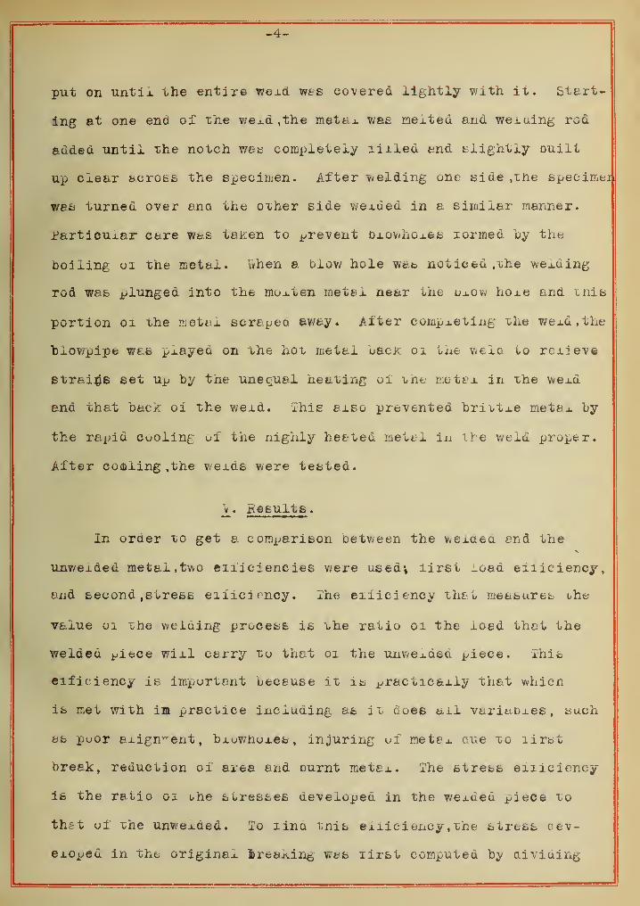
put on until the entire wexd was covered lightly with it. Start-
ing at one end oi* the wexd ,the met ax was melted and weiuing rod
added until the notch was completely liiied and slightly Duiit
up clear across the specimen. After welding one side ,the speeimei
was turned over ana the other side wexued in a similar manner,
rarticuxar care was taken to prevent bxov/hoxes formed by the
boiling 01 the metax. when a blow hole was noticed ,the wexding
rod was plunged into the moxten metax near one uxov; hoxe and tnis
portion 01 the metal scrapeo. away. After completing the weld, the
"blowpipe was played on the hot metal back 01 the weld to rcxiev©
strains set up by the unequal heating of the metax in the wexd
and that back oi the wexd. This axso prevented brittxe metal by
the rapid Cooling ui the nighly heated metal in the weld proper.
After coaling , the weids were tested.
V. Results .
In order to get a comparison between the v«exQea end the
unwexded metal, two eniciencies were used*, lirst load eiiiciency,
and second , stress efficiency. Ehe eiiiciency that measures ohe
value 01 the welding process is the ratio oi the load that the
welded ^iece wixl carry to that oi the unwexded piece. This
eific iency is important because it is ^racticaxiy that whicn
is met with im practice including as it coes ail variuDxes , such
as poor alignment, bxuwhuxes,injuring ui metax one to lirst
break, reduction oi area and ournt metax. The stress efficiency
is the ratio oi one stresses aeveiopea in the wexded piece to
that oi the unwexded. To lind tnis eiiiciency , the stress oev-
exOpeu in the original treating wts first computed by dividing

-5-
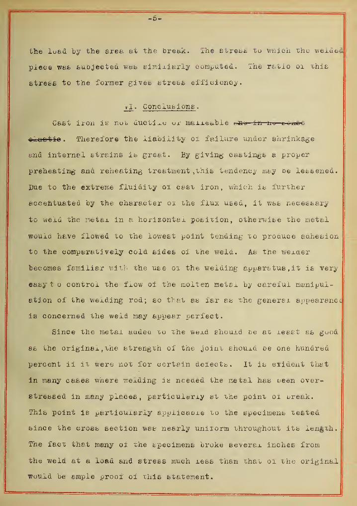
the load by the area at the break. The stresb to which the welded
piece wafc fcuojected was Bimiliaria commuted. The ratio 01 this
btrebs to the former giveb btrebs efficiency.
vi . Cone lub ions .
Cast 11*021 it nob ductile ui niaixeabie i.au in ae uoncc
olaotio . Therefore the liability 01 failure under shrinkage
and interne! btrains ib greet. By giving castingb a proper
preheating- and reheating treatment ,this tendency may De lebbened.
Due to the extreme fluidity 01 cast iron, which is further
accentuated by the character 01 the flux ubed, it was necebb&iy
to weld the metax in a horizontal, position, otherwibe the metal
wouxd have flowed to the lowest point tending to produce adhesion
to the comparatively cold sides 01 the wela. Ab tne wexaer
becomes familiar with the use 01 the welding apparatus , i t is very
eaby t o control the flow of the molten metsx by careful manipul-
ation of the wexding rod; so that as far as the general appearance
is concerned the weld may appear perfect.
Since the metal audeu to the wexd shouxd De at xee.bt as guod
st uhe originax,the strength of the joint bhouxa oe one hundred
percent ii it were not for certain deiectt. It ib evident that
in many cases wnere wexding is needed the metal has ueen over-
Btrebsed in many places, psrtieuxfctrxy et the point oi break.
This point ie particuxeriy aopiicaoxe to the specimens tested
since the crosb beet ion wet nearly unilorm throughout itb length.
The fact that many 01 the specimens broke several inches from
the weld at a load and stress much xess than that 01 the original
would be emple proof of this statement.

Breaks due to this original stressing cannot De charged to the
wexd. Causes oi iailure which may ue charged to the weld are,
burning, misalignment, and cooling strains. Burning may be
eliminated by using a slightly reducing flame. The method by
which this fx erne may he obtained is descriued in a pamphlet
published Ly the Oswald Acetylene Company.
"When the blowpipe is iirst lighted the acetylene is greatly
in excess. The ilame is oi abnormal volume, a airty yellow culor
and oi uniiorm consistency. This is the reducing type in an
exaggerated degree. By increasing the oxygen pressure the
size oi the flame is lessened and gradually u white zone oi
greater luminosity appears near the blowpipe tip. This luminous
zone is not yet clearly defined. The ixaxue is still oi abnormal
size ana is streaky in its appearance. The extent oi the reducing,
or carbonizing action of the fla^e is judged practically hy the
size and definition of the luminous zone. When the xuminous
zone becomes more clearly defined and takes the iorm and ooxor
of a bluish white incandescent cone or pencil, the streakiness
is diminished and the frame approaches neutral."
From tne fact that but three oi the specimens broke in or
near the weld,- and at least one oi these breads was due tu a
ulowhoxe,- it wouxd seem that burning oi the metax is a minor
defect, ruor alignment does not seem i-o be important ror it -was
noticed that several 01 the specimens which were very poorly
aligned gave very high efiiciencies . Cooling strains seem to
be the important element. This is evidenced by the large number
of breaks occuring a very short distance outside or the weld.

-7-
These strains could be materiaxiy eliminated by preheating and
slow cooling oi the metal.
Curves have oeen plotted with loaa eiiieienoies and stress
eificiencies as ordinated and numoer 01 weids, in the order oi
making, as auscissae. From these ihe average eiiicienc^ has
been caxcuxeted, and pxoi/ted as shown. The fact that the stress
efficiency is about two per-cent higher than the load efficiency
can be attributed to the iact that in the xirst breaking the
average sectionax area is larger then in the second. It was
pro cable that in tnose cases where the efficiency ran mucn over
one hundred per-cent the original specimen was a puor casting,
dus either "co blowholes or weejv metal, and these delects were
later exiniinateu uy the welding. Since in every case where the
wexded specimen uroke at a section xarger than did the original
specimen , the brea*. was seen to come at or near the edge oi the
weld, it follows tnat the metex had u&en injured in the wexding.
jjllthuugh an average exiiciency ox ever ninety per-eent was ou-
tained, the fact that several exxieieneies ran bexow eighty
per-cent would indicate that the exiiciency 01 the average
weiaer sh^Ux,d not ue rateu. higher than seventy-live ^er-cent
under ideal donaitions.

DATA SHEET.
llo.of: Area in sq. inches.: Ultimate strain lbs.: Position ofPiecej or^^nal^w£ld:_break^original:_weld ± fracture^&Remarks
1 .425 .552 .552 11910 94 002 .401 .484 .393 10410 94303 .402 .451 .393 11210 94754 .408 .535 .402 8580 85405 .416 .380 .389 10650 80807 .451 .500 .408 11700 103708 .340 .420 .382 8720 84 59 .442 .431 .425 11510 10390
10 .403 .452 .436 loooo 684011 .420 .473 .400 10825 880012 .410 .420 .406 10600 1072013 .407 .490 .422 10650 1095014 .405 .427 .400 6070 1078015 .446 .514 .403 11485 1158016 .435 .473 .381 103 75 893017 .404 .443 .381 11040 1044018 .444 .539 .426 12765 1207019 .436 .479 .398 11930 10900
.408 .451 .397 10650 11140
1?:.340 .517 .382 8720 5160.451 .562 .493 11700 10650
At3/33/41/21/41 1At3/81/2At1/23/41/8
edge of weld.2" blowhole." from weldn ?i n
" out ., Blov/hole/4" out.edge of weld." from edge.
edge ol weld." from edge.
3/4" out.3/8" "
1
/8" " crookedl/4 n
7/8"5/8"1/8"
7' & 8' are results obtained from welding 7 & 8 a second time.


Stress at Ultimate. Lbs./sq. in.: Efficiency %._Ori£inal._ __Weld_._ _:LoadJ_ _Stress_.
28000 i »?aaa /y AO DOU.Oc c a aa£6000 o A aa a OA Cy o . o yt- . 4c (v U c^l JU D A Ao4 . D DA Aob.D
c ±<2UU y y . o"1 AA A100 .
tODUU O AO i "iAfo . y D 1 c
AA<^04 UU do aOO . OAO -1
yo . ±
c o y \ju COT 1 ,A ob.y OO . 4o A A c,r> OA 1y u . i OC? Dyo . o
c4ouU 1 CWAAJ.D / UU AD /I00.4 DO • ft
c ( u fcK 'JU OX . O OD . ft
cDy UU *"> £.Ao4 UU T AT «3 1 m AIU1 • Dpap aa Of AAAtDUUU iuc • y y y • ft
15000 S7000 177.5 1 8.015800 28700 100.9 111.523900 234000 86.2 98.027300 27400 94.6 100:528750 283 94 .5 98.527400 27400 91.2 100.086100 28100 104.8 107.525700 13500 59.2 52.525 1' 00 L1600 91.1 83.5


U. OF I. S. S. FORM S


TENSION TESTS OF COMMERCIAL OXYACETYLENE YIELDS IN STEEL.
I. Introduction .
Previous to this time all available data as to the strengths
of oxyacetylene welds in steel have been representative of Job
shop practice. In order to widen the scope of this data concerning
the strengths of oxyacetylene welds in steel ,the writers have
undertaken to make a fairly comprehensive test of the welds as
executed by the best of expert welders. Bulletin No. 45 of the
Engineering Experiment Station of the University of Illinois, "The
Strength Of Oxyacetylene Welds In Steel" by Herbert L. Whittemore
gives in detail what may be expected from welds made by the most
proficient amateurs, and the results therein stated will be used
for comparison. The welds tested in this investigation were made
by expert welders in the employ of the Oxweld Acetylene Co. , at
their plant in Chicago 111., under the supervision oi the writers.
Since the procuring of the best welds was of the utmost importance
in these tests, the most modern apparatus was used, and plenty of
time was allowed for the execution of the welds. In order to get
an idea of the time spent and the materials used in making the welds,
data pertaining to these phases was taken throughout the welds.
The specifications as included herein £ive the essential points
of the treatment afforded the welded specimen. Where it is deemed
necessary , the writers will give additional notes on the details of
the treatment. The tests of the specimens were made at the laboratory
of Applied Mechanics, at the University of Illinois, under the
direct supervision of Professor Moore, of the Engineering Experiment
Station.
eicrao

_9
II . Specifications .
Material: -Flange steel plate manufactured by the open hearth
process
.
Chemical Properties : -The steei shall coniorm to the following
requirements as to chemical composition ,
-
Manganese <>.50g - 0.60fPhosphorous (acid) 0.05^
fhasic) 0.04%
Sulphur 0.05/0
Physical Properties : -The steel shall coniorm to the following
requirements as to tensile properties,
-
Tensile strength, pounds per sq. inch 55,000 to 65,000.
Yield podnt, minimum pounds per sq. inch - 50$ tensile strength.
iSize and Thickness of Plates: -The test peces shall be cut from
plates 52 1/2" x 18" and shall be of the following thicknesses ,
-
1/8", 1/4", 1/2" and 1". There shall be the fo lowing number of plat
for each thickness,
-
Thickness. Plates required.1/8" 2
1/4"1/2" l1" 8
Preparation of Plates: -Each plate of each thickness shall be marked
X, Y or Z, depending upon the number in the series. Each plate shall
then be sheered into five strips, A'B C D and E as per attached
blue print. (Fig.l. ) Each piece must be stamped distinctly with it's
letter o n each end. Pieces B C and D shall then be cut along the
lines T,Y-W. (Fig. 21 This should preferably be done with a t:haper or
planer in order that a beveled edge of 45 degrees be obtained for
welding. Do not use a cutting blowpipe on this operation.
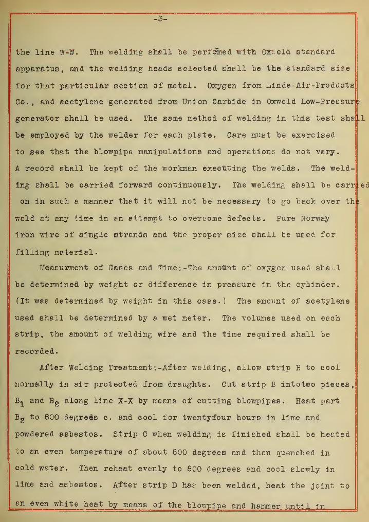
Welding: -Strips B, C, and D of each plate shall be welded along
-3-
the line W-W. The welding shall be pericfined with Oxveld standard
apparatus, and the welding heads selected shall he the standard size
for that particular section of metal. Oxygen from Linde-Air -Pro ducts
Co., and acetylene generated from Union Carbide in Oxweld Low-Pressurfe
generator shall be used. The same method of welding in this test sha .1
be employed by the welder for each plete. Care must be exercised
to see that the blov/pipe manipulations and operations do not vary.
A record shall be kept of the workman executing the welds. The weld-
ing shall be carried forward continuously. The welding shell be carried
on in such 8 manner that it will not be necessary to go back over th
weld at any time in an attempt to overcome defects. Pure Norway
iron wire of single strands and the proper size shall be used for
filling material.
Measurment of Gases end Time:-The amount of oxygen used sha.l
be determined by weight or difference in pressure in the cylinder.
(It was determined by weight in this cese.) The amount of acetylene
used shall be determined by a wet meter. The volumes used on eech
strip, the amount of welding wire and the time required shall be
recorded.
After Welding Treatment : -After welding, allow strip B to cool
normally in air protected from draughts. Cut strip E intotwo pieces,
and Bg
along line X-X by means of cutting blowpipes. Heat part
Bg to 800 degrees c. and cool for twentyfour hours in lime and
powdered asbestos. Strip C when welding is finished shall be heated
to en even temperature of about 800 degrees end then quenched in
cold water. Then reheat evenly to 800 degrees end cool slowly in
lime end asbestos. After strip L has been welded, heat the joint to
en even white heat by means of the blowpipe and hammer until in

-4-
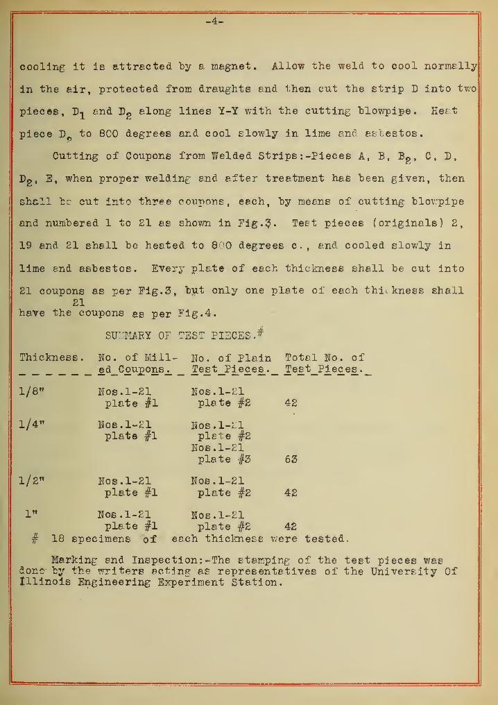
cooling it is attracted by a magnet. Allow the weld to cool normally
in the air, protected from draughts end then cut the strip D into two
pieces, D-^ end D?
along lines Y-Y with the cutting "blowpipe. He£ t
piece D„ to 800 degrees and cool slowly in lime and asbestos.
Cutting of Coupons from Y/elded Strips : -Pieces A, B, Bg , C, D
,
Dg, E, when proper welding and after treatment has been given, then
shall be cut into three coupons, each, by means of cutting blowpipe
and numbered 1 to 21 as shown in Fig. 3. Test pieces (originals) 2,
19 and 21 shall be heated to 8 jO degrees c, and cooled slowly in
lime end asbestos. Every plate of each thickness shall be cut into
21 coupons as per Fig. 3, but only one plate of each thickness shall21
have the coupons as per Fig. 4.
SUTTIARY OF TEST PISCES
.
#
Thickness. No. of Mill- Wo. of Plain Total Ko. ofed_Cou
j£ons JL Te_£ t_Pi_ec es_. _ Test_Pi_e£es_._
1/8" Nos.1-21 Nos.l-£lplate #1 plate #2 42
1/4" Eos. 1-21 Nos.1-21plate #1 plete #2
Nos.1-21plate #3 63
1/2" Nos.1-21 Uos.1-21plate #1 plate #2 42
1" Nos.1-21 Hos.1-21plate #1 plate #2 42
# 18 specimens of each thickness were tested.
Marking and Inspection: -The stamping; of the test pieces wasdone by the writers acting as representatives of the University OfIllinois Engineering Experiment Station.

-5-
Veriation from Specifications '.-Regarding the heat treatment of
the welds, this was carried out as per specifications, with one
exception. Instead of placing the various plates in the oven for
annealing and then cutting them up, it was thought best to cut them
up first and then anneal them. The main reason for doing this was
that the heavier plates could be hanr'eled much more easily. This
might have an important bearing on the results produced by annealing,
since a cutting blowpipe was used in cutting out. the coupons, for
if they were annealed before cutting up the effect of the annealing
would he done away with alone- the sides of the specimen by the
intense heat of the cutting operation. It being impossible to obtain
1/8" flange steel ,a No. 10 blue annealed sheet steel was used. All
steel used was obtained from the regular stock of the Joseph T.
Ryerson & Son Co., Chicago 111. Due to lack of time ,the waiters
tested only one plate of each thickness. Coupons Uos.lO, 11 and 12
ior each plate were not tested.
Note '.-These specifications are, with few exceptions, a copy
of those written by Mr. Bryce, Chief Engineer of the Oxweld
Acetylene Co., in conjunction with Professor Moore.

-6-
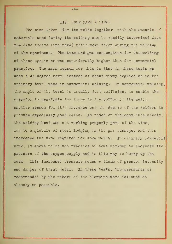
III. COST DATA & TIME
.
The time taken for the welds together with the amounts of
materials used during the welding can he readily determined from
the date sheets (included) which were taken during the welding
of the specimens. The time and gas consumption lor the welting
of these specimens was considerably higher than for commercial
practice. The main reason for this is that in these tests we
used a 45 degree bevel instead of about sixty degrees as is the
ordinary bevel used in commercial welding. In commercial welding,
the angle oi the bevel is usually just sufficient to enable the
operator to penetrate the flame to the bottom of the weld.
Another reason for this increase was th< desire of the welders to
produce especially good welds. As noted on the cost data sheets,
the welding heed was not working properly part of the time,
due to a globule of steel lodging in the gas passage, and this
increased the time required for some welds. In ordinary commercia
work, it seems to be the practice of some workmen to increase the
pressure of the oxygen supply and in this way to hurry up the
work. This increased pressure means a flame of greater intensity
and danger of burnt metal. In these tests, the pressures as
recommended by the makers of the blowpipe were followed as
closely as possible.


IV . Testing -
The specimens were subjected to tension in a Riehle 100,000
pound testing machine. The test coupons were prepared for testing
as called lor in the specifications. In order to measure the
elongation of the specimen , marks , at intervals of one inch for a
distance of eight inches, were made along the body of the specimen.
The area of the weld as well as the afcea of the specimen was deter-
mined before breaking. The area of the break was likewise noted.
The yield point end the maximum load were obteined from the curve
as made by the autographic attachment. Standard wedge grips were us
The grips automatically line the specimen in one direction, end the
faces of the cross heads were used to line them in the olher direct-
ion. All data obtained will be found listed on separate data sheets
and shown graphically by the various curves.
V. Calculations .
From the point oi view of the user,the value of the weld is
smeaured by it's efficiency as well as by it's ease of a plication.
There are two types of welds: namely, those in which the weldamy be built up or enlarged and those which require machining o
size after the weld has been completed. For the first of these,
a
so-called load efficiency is used. This efficiency is the ratio of
the load that the welded piece will bear t that load which an
unwelded piece of the same size f as the stock of the welded piece)
will bear. This evidently excludes cross sectional area oi the
weld. In figuring load efficiency ^pieces of identically the seme
cross sectional area (except for weld) should be used. In this
test , variations from this condition made certain modifications'
necesppr^
.


-8-
An average load lor the three unwelded Untreated pieces was taken,
and a correspondingly average area. For any variation of area
occurring on the other piecest ( either welded or unwelded and treated
it was simply necessary to multiply th s average load "by the ratio
of the arer of the piece in question to the average area. This
would give the load that the piece in question might he eypected to
hold if it were not v:elded or treated. The load efficiency for
this piece is the ratio oi the load as measured "by the machine to
this computed load.


- —r^r- ~
VI . Results
Specimens : -As received all of the welded specimens were more
or less warped, thj£ being more pronounced in the thinner specimens
then in the thicker specimens. The effect of this warping, however,
was not noticable since in every case the efficiency was well over
one hundred per cent. In every case , the cross sectional ares of the
weld was greater than that of the stock.
Defects : -Wi th "but one exception there seemed to be no burnt
welds, burning being gaged by the appearance of bluish spots in the
fracture. In several of the one inch specimens ,the primary cause
may be attributed to the slipping of t e weld f cue to edhesion
rather than welding) along the bevel. With the exception of the
burnt weld,all fractures occurring in the weld gave metel having
the same appearance. No blowholes were found in the entire serdes
of welds
.
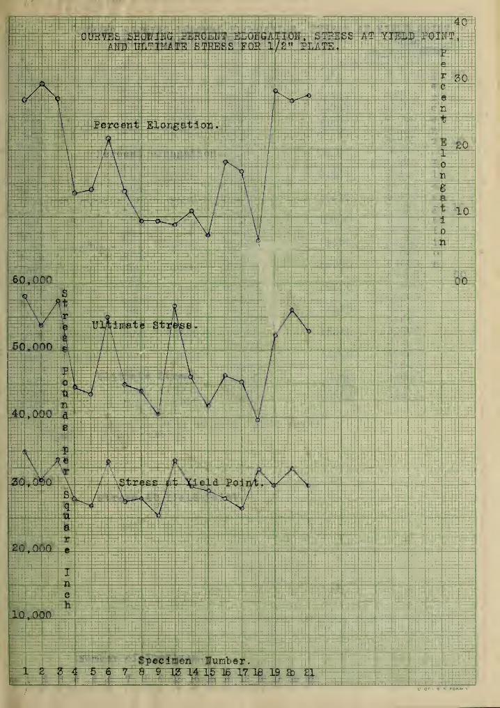
Elongation and Yield Point : -Regardless 01 the postiion oi the
break, ell specimens broke at a stress greater than the stress at
the yield point of the original metel. In every case noted the
yield point, as required by the specifications, occurred at a
point greater than 50% of the ultimate as found in the unwelded
untreated specimens as well as in the v/elc'ed. The curves based
upon stress at the yield point are of the same general type as the
curves bases upon ultimate stress; that is, the various treatments
accorded the specimens had. the same effect upon both stresses.
The effect of thickness (of plates) upon the stress at yield point
is small as shov.n by the following average stress at yield point;
l/8"-30,100 pounds per sq. inch, l/4"-34,514 pounds per sq. inch,
l/2"-29,847 pounds per sq. inch, end 1"-30,1££ pounds per sq. inch.


-10-
The most efficient method of treatment ef treatment of the welds as
regards yield point, as shown by the curves, is hammering. This
treatment was particularly efficient in the 1/6" and 1/4". The
hammering was not as effective in the thicker pieces fl/2" end 1")
as in the thinner pieces. This may he attributed to the decreasing
effect of blows of the hammer. In those pieces in which the spec-
imen was first hammered and then annealed /the effect Of hammering
was inappreciable since the stress in thiB case was no higher than
that in which annealing only was employed.
The curves bases on elongation show that welding decidely
decreases the per cent elongation. This would indicate that tests
of repeated stress and impact would be valuable since the elasticity
of the metal has evidently been decreased. Annealing, as shown by
the curves, increases the elasticity; on the other hand, hammering
decreases the elasticity. In the eighth and quarter inch pieces in
which most of the breaks occurred outside of the weld ,the elasticity
of the piece was not impaired as it was in the thicker pieces where
practically all of the breaks occurred in the weld.
Explanatl on: -When the plates were first rolled the steel was
given a hard surface without reducing the ductility. The welding
with its high temperatures and comparatively rapid cooling would
have a tempering efiect on the steel, thus decreasing the ductility.
Those plates which were annealed would in part be relieved of the
stresses set up due to this rapid cooling thereby restoring the
ductility ol the the original metal in part. The hammering by
giving a closer grained structure increased the elastic limit.

-11-
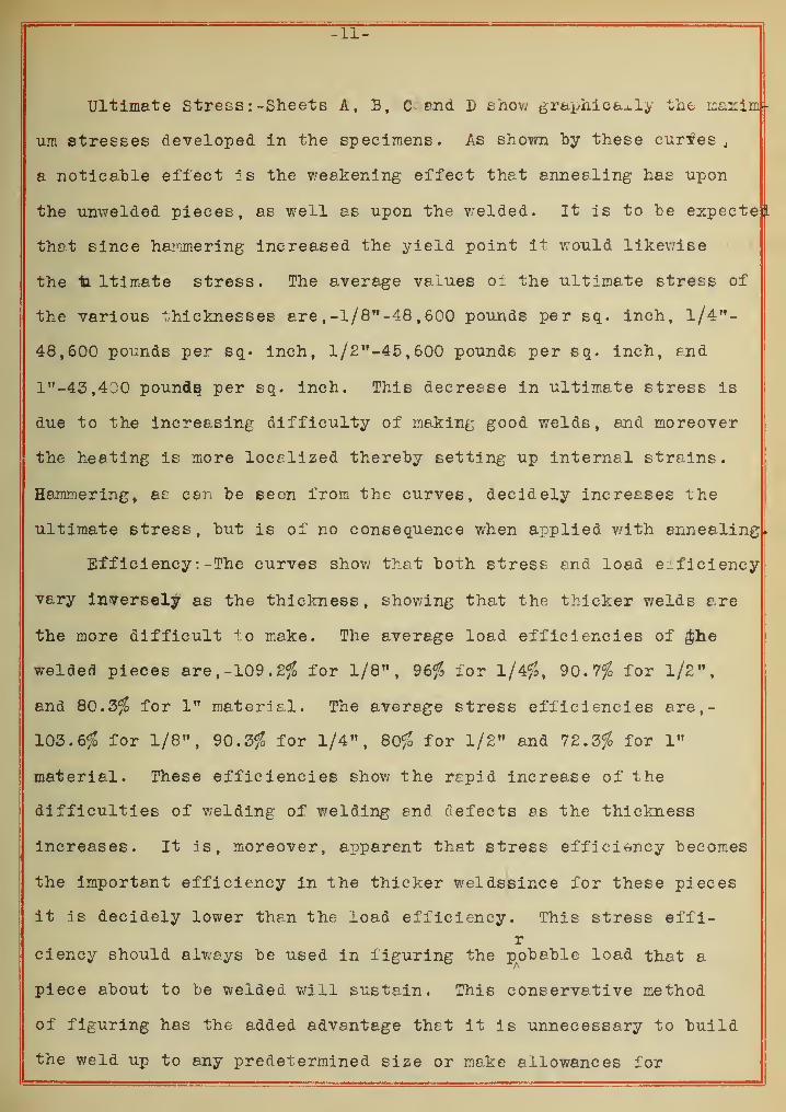
Ultimate Stress : -Sheets A, B, C and D show graphically the maxim-
um stresses developed in the specimens. As shown "by these curfes4
a notica.ble effect is the weakening effect that annealing has upon
the unwelded pieces, as well as upon the welded. It is to he expecte
L
that since hammering increased the yield point it would likewise
the "ta. ltimate stress. The average values 01 the ultimate stress of
the various thicknesses are ,-l/8"-48 ,600 pounds per sq. inch, 1/4"-
48,600 pounds per sq. inch, l/2"-45,600 pounds per sq. inch, and
1"-43,4J0 pounds, per sq. inch. This decrease in ultimate stress is
due to the increasing difficulty of making good welds, end moreover
the heating is more localized thereby setting up internal strains.
Hammering, as can he seen from the curves, decidely increases the
ultimate stress, hut is of no consequence when applied with annealing,
Efficiency : -The curves show that both stress and load efficiency
vary inversely as the thickness, showing that the thicker welds are
the more difficult to make. The average load efficiencies of $he
welded pieces are, -109. 2$ for 1/8", 96$ ior 1/4$, 90.7$ for l/2",
and 80.3$ for 1" materiel. The average stress efficiencies are,-
103.6$ for 1/8", 90.3$ for 1/4", 80$ for 1/2" and 72.3$ for 1"
material. These efficiencies show the rapid increase of the
difficulties of welding of welding and defects as the thickness
increases. It is, moreover, apparent that stress efficiency becomes
the important efficiency in the thicker weldssince lor these pieces
it is decidely lower than the load efficiency. This stress effi-r
eiency should always be used in figuring the probable load that a
piece about to be welded will sustain. This conservative method
of figuring has the added advantage that it is unnecessary to build
the weld up to any predetermined size or make allowances for


-12-
slippage of welds.
VII. COMPARISON OF EXPERT r_'0 JOB SHOP WELDS.
Mr. Whittemore's first series ol tests were "based on 1/4"
flange steel plates. In this series of tests various deviations
from standard practice were made. With the possible exception of the
case in which butt welds were ,iade,these deviations seemed to have
no noticable effect. His average stress efficiency lor the 1/4"
plate was 69.25$ while that of the experts was 90.3$. In the latter
case no variations in welding were made from standard practice, hut
several different treatments of the welded pieces were made. In
Mr. WMttemore ' s tests, the relatively high efficiency of the butt
welds was explained by the fact that the flame was confined almost
entirely to the surface of the weld which prevented, the deterioration
of the metal as noted in the beveled welds. In tests made by the
writers ,the beveled welds gave no evidences of deterioration, and
moreover allowed a considerably higher welding rate. The observation
of the writers would seem to indicate that there is greater liability
of the center of a butt weld being unwelded then of a beveled weld.k
It would, therefore, seem that there would be no object in The maingA
of butt welds, at least in expert practice. Moreover, it is evident
that it would be impossible to execute" reliable butt welds on the
thicker plates , due to the difficulty of penetrating the fracture.
A further consideration in favor of the bevel weld is the addition
of the high grade welding wire which possesses higher qualities then
does the original plate. TThile the worth of e weld is measured by
average efficiency of a series of tests(its reliability is measured
by the minimum efficiency. The average minimum efficiency of the


-.in-
former welds was 52.4$, a variation of 24.4$ from the average. In
the latter case the average minimum efficiency was 79.0$, giving
a variation oi 12.5$ from the average. It is this consistency on the
part of expert welds which makes them relatively more valuable than
the best amateur welds rather then the increased average efficiency
over job shop welds.
In the second series of tests, Mr. 7/hittemore used 1/8" plate,
both portions of the plate being beveled at 45 degrees. In this
series, as in the former, several different treatments were used.one
With one exception, all treatments were valueless. In set the weld
was hammered frequently as the relding progressed. in the testing,
varied results were obtained, but the general average was lower than
that of the other pieces. The conclusion was reached that the
increased density due to hammering was more tha.ii counteracted by
the subsequent annealing effect ol the welding flame as welding was
resumed. A similar conclusion was reached in the present tests
in which the weld was subjected to hammering after which it was
annealed. These values were no better than those obtained by simply
annealing the weld. A step further was taken in which the piece
was simply hammered. These results showed an increase in the
stresses at yield point and at ultimate. Such results show that
hammering is the desirable treatment . for oxyacetylene welds in steel.
The average efficiency obtained by Mr. Y/hittemore in this series
was 76.3$ with a minimum of 60.5$, giving a variation of 20.7$.
In the present series of tests the average efficiency was 103.6$
with a minimum of 88.4$, giving s variation of 14. GZ%. This scries
confirms the conclusions reached in the first series.
—==============—


VIII. GENERAL CONCLUSIONS.
Mr. Whittemore reached the conclusion that forging, aside from
increasing the strength of the welds, also increases the ductility
of the fused metal. In the present series of tests, the results
obtained show that the reverse is true as regards the ductility*
The yield point was practically independent of the efficiency in
both cases, and d^ d not vary appreciably from the yield point of the
material. Another conclusion reached by the former was that the
adding; of filler to increase the thickness was but a partial remedy
for increasing the strength of the weld because the adjacent metal
was always overheated. The latter tests brought out, further, that
exceedingly high e file iencies could be obtained on thin plates by
adding filler, pointing to the conclusion that overheating played
no important part. It would seem that this overheating plays an
increasingly important part in the welding of thicker plates since
the efficiency fell as the thickness of plates increased even though
the plates were built up. This might be attributed to the fact
that while the area for radiation remains the seme the region 01
intense heat is greatly increased.
In his final conclusion , Mr. Y/hittemore claims that a stress
efficiency of 100$ is unsupportable . The present tests, showing
an average efficiency of 100$ for 1/8" plates, does not bear out
ihis claim, but it would doubtless be unsafe to base calculations
on such efficiencies, a conservative- extimate being about 95$
providing the welders be proficient and plenty of time is tcken
for the work. As the thickness increases from 1/8" to 1/4",
1/4" to 1/2", and from 1/2" to 1" this efficiency of 95$ should be
decreased about 10$ per interval.

From the above tests it has "been shown that the quality of the
metal has "been affected. One of the most serious defects noted
was the decreased ductility, particularly in the thicker specimens.
It is well known that ductility indexes the ability of steel to
withstend shock and repeated stress. It would, therefore, appear
that further tests partaking of the nature of impact and repeatedto
stress should he run before final conclusions asAgeneral velue of
oxyacetylene welds are drawn.

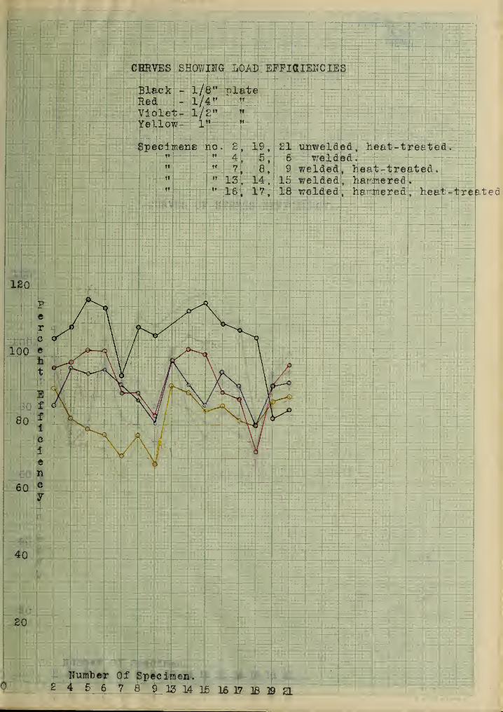
CHRVES SHOWING LOAD EFFICIENCIES
Black - 1/8" relateRed - 1/4 ,f ,T
Violet- iff" "
Yellow- 1" "
Specimens no- 2" " 4tf ft TJ
11WW I i w i
19, £1 unwelded, heat-treeted
.
5, 6 welded.8, 9 welded, heat-treated.
" 13, 14, 15 welded, barriered
.
" 16, 17, 18 welded, ha Tiered, heat-treated
40
20
Number Of Specimen.24 56 78 913 14 1516 17 18]9a
aaioTiaisira aAOu occwdh3 ssvcto
?T ^\I - J&9HMS\l -*9lo:7"I -^roIXeY
. fioJsstit-jfasrf .fisblewrxxr 13 ,21 ,3 .on arranr.toeqS
. hob!a\7 b . 3 "
:
11 1
111
it »»
Tt tT
0*
OS
.rracriascrS 10 todmsiVL
js a vi ai ai m si e 8 ? a a ^ a <j>


. nam! 09q}3 10 t

CURVES SHOWING STRESSES AT ULTIMATE AND ELASTIC LIKIT.
HUI/EER 10 BLUE ANNEALED STEEL. f Approximately l/8")
reee
Yield Point
£0,000
101000
Number of Specimen.^ n01 2 34 5 6 78 9 M 15 16 17 18 39 3) a

r2U0
2 ooo t oao
I: n*3 etamWXU r A-
4
rir>
'xr OGO ,0£3
taiO* BXeXY ft 3 339«/A / N \ I A
000,02
000{0X
ra or or «r •i»cr(to»tT3^^o tndmuli
<h ec 8x ?x ax ar lie e ^ v a 3 ^


U. Of I. S. * FORM a
r
••
i lyiHHl
T^ zi. 1 T i, ; ft
>
>
5?S

DATA SHEET.
Ho . of :?osition:Area :Elastic LimitPiece . j racxur
e
• C! ri It1
. <l . J.IJ . : lbs
.
lbs. /sq.in..WO . ±U blue annealed steel plate.
T AV±A1 TJ A Hff 9 A A• too 8100 . 30450
AT UTip • • COO C\ r\ r\ t\9000 31900% AV B . •
.
9 A A• COO 8000 30000
A T5V B.I.W. • C ^6 11700 43000W«l A
• ftUU 29250C-DV0±5I
T3 A TilB . O.K. . c f ft 11900 43500weia. 31800DX5I B.O.M. 5>*7 A 12000 43500
Wciu . OOft 31200/ X5I J U U J ip
.
QA 9600 32450W6 -LG A '"> A 22550
ax grip
.
10000 33600we j.q.
/OA1 V 23500
Q'D'V At grip. on? 9800 33450wexfl. /I "7 O 223001 / TYV B.O.M. . do 11000 39300w ei.cL . OO 290001 A T\V jj. U.K. • (SO / 11400 39700wexu . OO O 294001 A TYV Al gi 1 p
.
8500 29300wexa. A 0»7 20900J.YD I Ao grip
.
I7AO 10350 34225Weld .414 2500018DY B.I.W. .286 9800 34300Weld .291 2505019EY .295 6900 2340020EY .279 8900 3190021EY .289 6000 20750
: Ultimate Strain.: _rt>SjL i^s .
/s^. in_.
12850 4830014000 4950012500 470001 T A AA13900 51150
3480015050 55000
402501 /ACA14850 53800
38 70013170 44500
3085015300 51400
3590014650 50000
3340015000 53600
3950015 600 r~ a A r\ r\54400
4020014520 50200
3565015260 50700
3710014300 50000
3660011450 3880012750 4570011500 39500
B.O.M.B.I.W.
- Broke outride of eight inch marks- Broke in weld.


Elongation. Efficiency <f>.
in. in 8" $ _str_e_B£ ._ ^oad^
0.72
0.8.931.85
1.17
0.72
0.90
1.20.
0.74
11.610:6
14.6
105.2
74117
105 . C
Tin117
9 . 1±4 .114- ^
94.
O
94 . o
109
106 106
11.25 114
15.00 116 116
107 107
108
78
108106
9.2682
84.7
82
84.7
DATA SHEET.
HO . 01 : Position :Area : Elastic Limit : ultimate Strain
.
Pi ec e :Fracture :Sq.in. : lbs . Lbs./sq . in
.
: ids. Lbs . / s
q
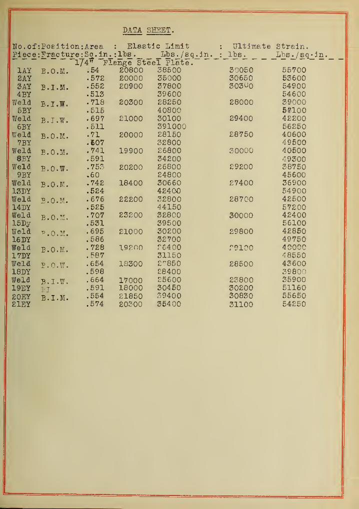
174" Flange Steel Plate.1AY B.O.M. .54 20800 38500 o ^UOU OO /UU
. 572 20000 35000 .jUOOU CiZCAAO^DUUoAY E.I.M. .552 20900 37800 OUvj^U D ft UU/ T3-V .513 39600 K/ C AAD ft UU
we la B.I.W. . 718 20300 28250 fcOUUU o y uuuOJ3I .515 40800 Km r\n1 1 U U
We la B.I.W. . 697 21000 30100 4 AAft c <iUU
. 511 391000i ,• e i a B.O.M. .71 20000 28150 1 DU / ACAAftUOUU
/ril .E07 32800 / Q RAAft J D UU
Weia. . 741 19900 £6800 «5 UUUU 4 ACAAftUOUUor! I .591 34200
w 61 a c • U . W •. 753 20200 26800.60 24800 400UU
we la "RDM .742 18400 30660 C n/ Art/ 4UU
1 <7TYVloUl .524 42400 oft y uuw e 1 a B.O.M. . 676 22200 32800 A 9 RAAft /CO UU~1 / TY\714D
I
. 525 44150 1 cL UUwei a
Jj . U • 11 •. 707 23200 32800 «5uuuu >1 O/AAftCftUU
1 RTW~lOlty .551 39500 CC1 AAO D1UUw e1a "p.o.:!. . 695 21000 30200 tsVoUU / CCCAftcODUT C T\VloDi .586 32700 ft V f D UVila! rlwe la B.O.M. . 728 19? no £6400 ! vluu ^ AAA A
ft u u
1 f DI .587 31150 /DKCAft o o o u
vv eiu B.Q.W. .654 13300 £"850 tyOOUU Annto ouu.598 £8400 39800
Weld B.I.W. .664 17000 £5600 £3800 3590019EY PI .591 18000 30450 30200 5116020EY B.I.M. .554 21850 39400 30830 5565021EY .574 20300 35400 31100 54250
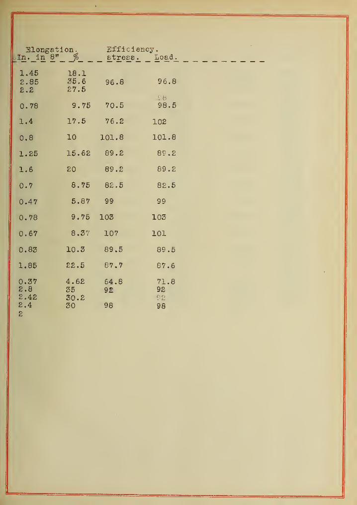
Elongation. Efficiency.In. in 8" fo stress^ Load_.
1.452.852.2
18.135.627.5
96.8 96.8
0. 78 9.75 70.5£•8
98.5
1.4 17.5 76.2 102
0.8 10 101.8 101.8
1.25 15.62 89.2 89.2
1.6 20 89.2 89.2
0.7 8.75 82.5 82.5
0.47 5.87 99 99
0.78 9.75 103 103
0.67 8.37 107 101
0.83 10.3 89 .5 89 .5
1.85 22.5 87.7 87.6
0.372.82.422.42
4.623530.230
64.892
98
71.8929298
to

DATA SxiEj '.T
.
No. of: Position : Area Elastic Limit
.
: Ultimate Strain.?iec£: Fracture :Sq.in. : lbs. lbs . j/s c^. in
.
1 lbs._ _lb Sj_/ iSq^in . _1/2" Flange Steel Plate.
lAy B.I.M. 1.036 36100 34900 60000 580002AY 1.061 32400 30500 56900 536003AY 1.038 35000 33700 59440 573004BY B.I.W. 1.010 34600 55200
Weld 1.254 34900 27800 55800 444005BY B.I.W. 1.050 33300 54200
Weld 1.309 35000 26800 57000 435006BY B.O.W. 1.012 33400 55000
Weld 1.213 338 27850 55700 458007BY B.I.W. 1.082 32100 52700Weld 1.280 35000 27300 57500 449008BY B.I.W. 1.110 31400 49550
Weld 1.252 34900 27900 55000 439009BY E.I.W. 1.110 29000 46000
Weld 1.26L 32200 25300 51000 4050013DY B . I . M • 1.014 33500 56600Weld 1.160 34000 29300 57500 4955014DY B.I.W. 1.020 33900 52400Weld 1.161 34500 29600 53500 4610015DY B.I.W. 1.047 34200 48950Weld 1.227 35700 29100 51240 4175016DY B.I.W. 1.100 33000 54600Weld 1.300 36200 27900 60200 4625017DY B.I.W. 1.110 30600 52200Weld 1.27D 33900 26500 58000 4530018DY B.I.W. 1.100 32700 45750Weld 1.275 36000 32000 50500 3950019EY 1.115 33100 29700 58200 5220020EY 1.070 346C0 323^0 60000 5600021EY 1.120 33200 2965o 59100 528 00
591

Elongation * Efficiency. /o
In. in 8". 2 .
stress
.
Load.
2.19 27.42.37 29.6 93.8 93.82.22 27.75
1 . 08 13 .
5
77.8 96.7
1 .13 14 .
1
76.1 94.9
1. 73 21.65 96 96.1
1.10 13 . 76 78.6 91.9
0. 75 9.37 76.8 87
0. 75 9 .37 71.5 80.3
1. 73 21 . 60 99 .1 99.1
. 71 8 . 87 80. 7 91 .
9
0.51 6.37 73.1 85.6
1.46 lo . 2 81.0 95.5
1.35 lb . y 79.3 91.5
0.50 6.«5 69 .
2
802.30 28.8 91.5 91.52.19 27.42.25 28.1 92.5 92 .5


DATA SHEET.
jn . 01 •.Position -.Area :Elastic XJXlilX : Ultimate Strain.XX C •.Fracture :Sq. in. : lbs.
One IncK FlangeXt L) b . / B Q . 111.
ox-eex irxane.: ids . Lbs
./sq. in.
X rt I x . Ox ( 40000 50400 r 7nnni- 1 /UUU
/Oil I 1 . O / TT *«/ <J \J W T 8700 522007 AY X • t^to 5Rnno 50750 71 flnn f w w
X . O X l47100x r Xvv/
itcxU. 1 RPX . D C 41500 A2(^nn 40800±, . oco 45500
WpI ri xj . x • < • 1 48 45000 CU1UUA"RY 1.487 44550
Ircm JD « X » n .1.64 49000 P980O aAnno
7"RY 1.52 40750WpI 1.76 41 noor± XVJ WVJ 25400V> V_/ a? oon 55200l-/ l** V/ V/
R"RY 1 A AX . DO 44250WpI(ICXU xj • I • W • 1 675 41 000*±X \J ww ar Ann 41000
•7XJ X 1 AR7 59500WpI 1 AftX . DO /conn A?4.nn 571001 5"DYJLiJ U X 1 49II C 1U P T WXJ • X • VI • 1 64 RRnnn 7fiQ nn "X DXVU1 /1TW 1 4R 51600WpIH C XU. .D • X 1. • 1 6"3X • uc R AnonO OU UU 7 a Ann
/ DO UU 470001 A T)Yxy x/x 47550WpI d T3 T T" 1 4? /l a Ann OC\J\J\J D^tOy U 446501 ATYVxux>x 1 . 485 49200it cxu. B . I . W
.
1.65 50000 r>rt nnn 442001 7TYVX 1 JJ 1 1.55 46850Weld E.I.W. 1.6G8 49000 P9000 71700 4250Q18DY 1. 54 46000Weld B.I.W. 1.745 45000 25800 71000 40.6(00
19SY 1.605 44900 28000 80700 5020020EY 1.59 55000 59700 81200 5840021EY 1.614 45000 54100 82200 51000

Elongation. Efficiency %.in^ in__8^_._ _j
r
o_ stress^ load^
2.72.252.36
0.75
0.47
0.55
0.75
0.49
"1 Ap
1.00
n
0.82
0.652.43
2.15
33.828.129.5
9.4
5.9
6.9
9.4
6.13
12.5
10.0
8.130.4
26.8
90.5
70.7
70.7
69.7
61
71
64.3
83.4
81.4
77.5
76.8
73.7
70.487
88.4
90:5
81.9
78.7
77
70.6
76.9
68.2
91.6
89
84
85.5
81.2
8087.2
88.5


Welding Test
Observers.
X y y
1 Pate2 Opentor8 Blowpipe used
4 Slso Welding Head
6 Material Welded
6 ThioJmees of Stock
7 Length of Weld
8 Angle of Berel
9 Time, Start
10 " Stop
11 welding
12 welding Wire15 " " need
14 Stock, Before welding
15 After16 " Addod
17 Acetylene Sni-ply
18 Start
19 •» 8top
20 "
21 " Pressure
22 Oxygen Supply
23 " Start
24 " Stop
26 H Differenoe
26 " Used27 " Pressure
28 Room Tesperature
In.In.
dec
rain.
lb.-ox.
/C ¥S^/6&3JZ & ,6J
3d**& "A.'<r*H**rr /at cat
2- /W~7
<s2 6£ * j9t/j*±£-/r *sr^-t res?9 /ft*. 7
/xj.z /tt.f /ff.tA 7 ¥, f # f
/ss; 7U7 7/ 9
/67 7
¥.3
lb.-os. ~ 7lb. -oz. -i2lb.-os. 0-6on. ft. ift42lb./sq.ln.
/66 e-t/.^ r;
t*0~j8L/<20-06 ~<=L
//<?-?t-7
//?- <? //'/-/
6-j 0-6
.•o.-.fnhr. 67 6 .7 6 7 6 2 6? 6&


Log Sheet
&tf
gelding Ta«t
Observora
1 Pat*2 Operator3 Blowpipe Heed
4 Else Welding Head
6 Meterial welded
6 ThlekneBB Of Stoc*
7 Length of Weld8 angle of Betel
9 Time, Start
10 " Stop11 " Welding
12 Welding Wire
IS " " Ueed
14 Stoak. Before !7eldiue
15 « After
16 " Added
17 Aoetylone Supply
18 " Start
19 " Stop
20 " Used21 " Free sure
22 Oxygen Supply
25 " 8tart
24 " Stop
25 " Differenoe
26 " Ueed
27 " PreeBare
26 boojb Teaperaturo
V-/-/S -
x r yz
F
£, flirts
in.
in.
dep.7. 7. /s-
xnln*ft****
ib.-o«. c ~y ~6
lb .-os*lb.-os.lb.**oz
•
c-7
9~?f- /J
I7-/C
0-f
/0~310 -7
0-/0
^0 -J
On* ft*
on* ft*
on* ft.
In. eater
/>T£.V ^0?0 ^=>/J. f if?./
/c* y
<20/. /
f //•/
lb .-02*
lb *-os.
lb *-os*
on* ft.lb./sq. in*
/00 *r.
/T9 - // - 7/S—
/t¥-/J H7'0//«?-/«? J/sr-/f/ - o /-
/
0'//Z7
j!—//*?-V^//^- /*=>
J - /
•jtjggrttm
MC tm:-

I
jtj

*3LOg ShMt
1 Date2 Operator8 Bloepipe Uaed
4 •!> Wldlng Head
6 Material Welded
6 ThleJcnese of Ftock
7 length of Weld
8 Anglo of Betel
9 Tine, Start
10 " Stop
11 • Weldlac
12 Welding wire13 * " need
K
V-/7-/S
r
in.in.
J
In.//
7/777^
/.tT&
lb.-oz.
14 Stock, Before aiding16 after "
16
lb.-oa.lb.-oa.lb.-oa.
0-/9*9-/ /&-?ft-*/-¥
if-/4/0-/0
2T~/39-//Me
/-//
9C-6
17 Aoetylene Supply
18 " Start
19 « 8top
20 " Oeed
21 • Pressure
en. ft*
on* ft.
on. ft.
ia. water
999, S
20.7 *//. S
S9£.0
22 Oxygen Supply25 Start
24 " Stop
25 Difference
26 " Used
27 " Preset!re
lb.-oa. /¥Z -'9 /9*-9lb.-oa. /J?"/** /9?-2lb.-oa.
cu. ft.
lb./sq in. *2/
-2-/<Z&. /
28 Boom Temperature dec. WUN 70 70 7C
Welding fleet
0b.er.er.. *£&t£!2t*M'J*'
9-/F~/JT ^fV-/r v-ttsir y-//-/r
&jt *d T*____
7 r;7 j_£ 9ty &/y, . ¥C 2£ £;/? £1/7& /0 ifiF**
/.'J7** /t**** 9/**
/-/37-0 //"-//
22-
9
/9-9'-9 0-9
/0t/. 9 /0j£.i>
//</9. * /Ct/,9
0-/9 ^-9 43-/ l^JL /~ML3?~¥ 37-0 /£-//
4SB*m W-/0 2?~ 9 /9-9V-/0 /- € '-9 0'9 *-AT
77£? 7?/.£ /ff/.9 s<?J*<* *?<r.ie
79/,/ ?9f.fi /'</?. * /C4/.9 9**'*/7. 9 $?.<2 tt? >
/^7^7 /tt-ze /?<2-/e /df-y /9£-j/3<r-C /9f-7 /Z9-9 /3Z-/C /??-//
/-? ?-//*./ VS.G 3*£f 29* &9*^
7C 7>£> *9 *r
s
«
)
E
!
i
l
\
I
!

Log Sheet <
1 Date
I Operator8 Blowpipe Ueed
4 Slee Welding Head
6 Material Welded
6 Thickness of Stock:
T Length of Weld
8 Angle of Bevel
f Time, 8tart
10 " Stop
11 welding
18 welding Wire
Uj • " Ueed
14 Stock, Before Welding
IE After
16 " Added
17 Acetylene Supply
18 " Start
19 Stop
20 " Ueed
21 « Pressure
22 Oxygon Supply
23 " Start
24 Stop
26 " Difference
26 N Ueed27 Pressure
28 Temperature of room
in.
in.dor;.
min.
lb.-os.
lb .-OS*
lb.-oz.
lb.-OB.
OU. ft.
OU. ft.
OU. ft.
in. water
lb.-os.
lb .-08 .
lb.-os.ou. ft.
lb./sq.. in.
dag. fahr.
i <• & u & *3* J O -
m
Y
/' //
2t&
2 ~J$ 7-7ft ~3
*2 Z3-6
(2* US 4£ 4~£>
/0f
7&7*2.$
7^>£. ¥77^ . 7 7<2<$, 3^7-3 7¥. I
_—5^-
/¥2~JJ37-7
/¥*-/¥t¥<2-3
#-//7S.C
6£L
\
K
\\
gt
welding Test
Observers . . ,1&!5

^ o •O P U -p
o to
CO a> «H ©© O -POof!vH «H <p £dftE o
«H <HiH-P O COH CQ (a p)
S p co +3
ft, ^
A
O O03
P'dH P£ to
• VrO -P
•
CQ-p EH
pi&M
ft JO
^:c o© • S3© M M
Po ••d
VVB
©o
CQ ofcH H
•d©U
EH
© •HX
C* © COO OJ
oCO CO
a 07 COo P E-t
•H © CO•P H© ft EH
©Oo
cr1
40
30
20
L0
)0

x>e Sheet
At. /frt tKf.htl. ff.f.f£K'L mA/f*
welding Tttt
Observers...
1 Date
f Operator
8 Bloeplpe Used
4 91m Welding Head
6 Jaterlal Welded6 Ihiokness of Stock7 Length of weld8 Apgle of Berel
9 Tine, Start10 » 8top11 • tiding
12 folding Wirt13 17 ted
14 3Took, Before rtldlng16 * After "
16
17 Aottyl<18 "
19 "
1021
SojplyStartStopUtedPress art
22 Oxygon Supply26 Start24 " Stop2L " Difference26 " Uted27 Pressure
In.
In.
&QC<
Bin.
lb.-os.
lb.—os
.
lb.-OB.lb.—os.
ou. ft.
ou* ft.
oa. ft.
in. eater
lb. -os.lb.—OS
.
lb .-OS.CO.. ft.lb./tq.in.
Jr. fX S PAS
X
//f4f —
<2zcJ£ Z iff**Z^Z52£
/.ft**
7Z+/977-
*
36 7Z~67T-// 76-//
z-z~ v-ir
J2 * Z>rA*4. <£Vr H^sFJ- C? jSTAs**^? 7//fe.c /jzj.sr zossf/zsr/.Z /JzJ.S' /7ZZ,Z 2ft. 7/sr/,Z 7/. 7 /fZ,7 J3I.Z
w-z/3~Z. 3£0
r
zi
32- Z
Z
7S~
~£79?M
z.f7^
f-z\7Z-J
3f4 . 9we* f
Z. /AS£>*-
/v-z-z
~7J. £ /*Z.5~
JZ/-0
Z
ns'-z
7Z. Z/£i-Z
28 ^saptraturt of Boost dtg. fahr. 6 Z* ft *z

60,000 n00
i20,000 n
c
h
10,000
Uumber of Specimen.
2 3 4 5 6 7 8 9 13 14 15 16 17 18 It 20 a

00 xMi'jW0