testo 760 · Digital multimeter · • The instruction manual contains information and instructions...
26
testo 760 · Digital multimeter Instruction manual
Transcript of testo 760 · Digital multimeter · • The instruction manual contains information and instructions...

testo 760 · Digital multimeter
Instruction manual

1 Contents
2
1 Contents 1 Contents ........................................................................ 2 2 Observe prior to use! ................................................... 4 3 Safety instructions ....................................................... 4 4 Intended use ................................................................. 5 5 Overview ....................................................................... 6
5.1. Display and control elements ........................... 6 5.2. LC display ........................................................ 7 5.3. Control key functions ........................................ 8 5.4. Further functions .............................................. 9 5.5. Explanation of icons ......................................... 9
6 Operating the instrument .......................................... 10 6.1. Switching the instrument on ........................... 11 6.2. Switching the background illumination on/off . 11 6.3. Switching the instrument off (automatically/manually) ....................................... 11
7 Carrying out a measurement ..................................... 12 7.1. Preparing for measurement ........................... 12 7.2. Voltage measurement .................................... 12 7.3. Current measurement .................................... 13
7.3.1. testo 760-1 ............................................................ 13 7.3.2. testo 760-2/-3 ....................................................... 14
7.3.2.1. 10 A jack ............................................... 14 7.3.2.2. µA/mA jack ........................................... 14
7.3.3. Clamp meter adapter (0590 0003) option (testo 760-2/-3) .................................................. 15
7.4. Measuring resistance, capacitance, continuity and diode test ....................................... 16
7.4.1. testo 760-1 ............................................................ 16 7.4.2. testo 760-2/-3 ....................................................... 16
7.5. Frequency measurement (testo 760-1) .......... 17 7.6. Frequency measurement/duty cycle (testo 760-2/-3) ..................................................... 17 7.7. Temperature measurement (optional) (testo 760-2/-3) ..................................................... 17

1 Contents
3
8 Service and maintenance .......................................... 18 8.1. View of the back of the instrument ................. 18 8.2. Replacing the batteries .................................. 18 8.3. Changing the fuses ........................................ 19 8.4. Maintenance .................................................. 19 8.5. Calibration ..................................................... 19 8.6. Storage .......................................................... 19 8.7. Cleaning ........................................................ 19
9 Technical data ............................................................ 20 9.1. General technical data ................................... 20 9.2. More technical data ....................................... 21
9.2.1. testo 760-1 overload protection (10 A fuse) .......... 21 9.2.2. testo 760-2/-3 Overload protection (10 A fuse) ..... 22
10 Tips and assistance ................................................. 24 10.1. Questions and answers ............................... 24 10.2. Accessories and spare parts ........................ 25
11 Protecting the environment .................................... 25

3 Safety instructions
4
2 Observe prior to use!
• The instruction manual contains information and instructions which are necessary for operating and using the instrument safely. Before using the instrument, read the instruction manual carefully and comply with all aspects of it. Keep this document to hand so that you can refer to it when necessary. Forward this documentation to any subsequent users of the instrument.
• If the manual is not followed, or if you fail to observe the warnings and instructions, there is a risk of fatal injury to the user and damage to the instrument.
3 Safety instructions
• The instrument may only be used by trained personnel. During all operations, please observe the Employers' Liability Insurance Association provisions for health and safety at work.
• In order to prevent electric shock, take safety precautions when working with voltages greater than 120 V (60 V) DC or 50 V (25 V) rms. AC. These values are the limit for contact voltages in accordance with DIN VDE (values in brackets apply to restricted areas, for example agricultural sectors).
• The measuring instrument may only be used in 16 A fused electrical circuits up to a nominal voltage of 600 V (testo 760-1 and -2) / 1000 V (testo 760-3). The nominal cross-section of the connection cable must be taken into account in order to ensure safe connection (e.g. via crocodile clips).
• Measurements that are dangerously close to electrical installations must only be carried out under the direction of a qualified electrician, not by oneself.
• The instrument may only be touched at the designated grip areas, the display elements must not be covered.
• If the safety of the operator and his surroundings can no longer be guaranteed, the instrument must be taken out of service and prevented from being used inadvertently. This is the case if the instrument: • Is obviously damaged. e.g. - Housing breakages - Defective test leads - Leaking batteries • Does not carry out the required measurements • Has been stored too long in unfavourable conditions • Has been exposed to mechanical stresses during transit.
• Prevent the instrument from being heated due to exposure to direct sunlight. This is the only way to guarantee the instrument will function perfectly and have a long service life.
• If the instrument needs to be opened, e.g. to change a fuse, this may only be carried out by a qualified specialist. Prior to opening, the instrument is to be switched off and disconnected from all electrical circuits.
• Maintenance work that is not described in this documentation must only be carried out by trained service technicians.
• If the instrument is modified in any way, operational safety can no longer be guaranteed.
• Only use test leads and terminals listed in the Accessories and spare parts section in this documentation.
4 Intended use
5
• Modifications or alterations to the instrument will result in the complete invalidation of any warranty or guarantee claims against the manufacturer.
• It is not permitted to use the instrument in an explosive environment. • Before and after use, always check that the instrument is in peak
working order. Test the instrument at a known voltage source. • The instrument must not be used while its battery compartment is
open. • Batteries must be checked before use and changed if necessary. • Storage areas must be dry. • If there is any battery leakage, the instrument must no longer be used
until it has been checked by our Customer Service. • The battery acid (electrolyte) is highly alkaline and electrically
conductive. Risk of acid burn! If the battery acid comes into contact with your skin or clothing, thoroughly rinse the areas affected immediately with plenty of water. If battery acid gets into your eyes, rinse them immediately with plenty of water and seek medical advice.
4 Intended use
The instrument may only be used under the conditions and for the purpose for which it was designed: • testo 760-1 conforms to measurement category CAT III with a rated
voltage of 600 V to earth. Measurement category CAT III is for use in electrical circuits in building installation, e.g. distributors, circuit breakers, cabling, sockets, switches, instruments for industrial use, permanently installed motors.
• testo 760-2 and testo 760-3 conform to measurement category CAT IV with a rated voltage of 600 V to earth. The CAT IV measurement category is used at the source of low voltage installations, e.g. building connection, main fuse, and meter.
The instrument may only be used in the fields of application defined in the instruction manual. Any application deviating from this is considered to be improper and unchecked use and may result in accidents or instrument damage. Any improper use will completely void any right to claims under Testo’s guarantee and warranty. The manufacturer is not responsible for damage to property or personal injury caused by the following: • Failure to observe the instruction manual • Instrument modifications not approved by the manufacturer • The use of spare parts not approved by the manufacturer • Use under the influence of alcohol, drugs or medication The instrument must not be used for the following purposes: • In potentially explosive atmospheres: the instrument is not explosion-
proof! • When there is rain or other precipitation: risk of electric shock!

5 Overview
6
5 Overview
5.1. Display and control elements
1 Control keys 2 LC display 3 Grip area 4 On the rear: battery compartment and bracket for the probe tips 5 On the rear: stand 6 Input jack
• testo 760-1: voltage, resistance, continuity, diode, capacitance and frequency measurements
• testo 760-2/-3: voltage, resistance, continuity, diode, capacitance, frequency, duty cycle and temperature measurements
7 Ground/COM jack for all measurements 8 Input jack for AC and DC mA/µA current measurement (up to 600 mA)
(testo 760-2/-3 only) 9 Input jack for AC and DC current measurement up to 10 A

5 Overview
7
5.2. LC display
1 Direct current/voltage 2 Alternating current/voltage 3 Diode test and diode continuity 4 Low-pass filter 5 AUTO mode is the default setting in all measuring modes 6 Dangerous voltage, AC ≥ 50 V, DC ≥ 120 V 7 Maximum, minimum, average measurement 8 Hold is activated, LC display holds the current reading 9 Battery capacity display
Display Feature
No Symbol Battery capacity 100 – 30%
Battery capacity 30 - 15%
Battery capacity 15 - 2%
flashes and acoustic signal emitted
Battery capacity 2 – 0%, instrument switches off automatically
10 Automatic power-off function is activated 11 Measuring units 12 Analog display (testo 760-2/-3 only) 13 Indication of polarity in bar chart (testo 760-2/-3 only)
5 Overview
8
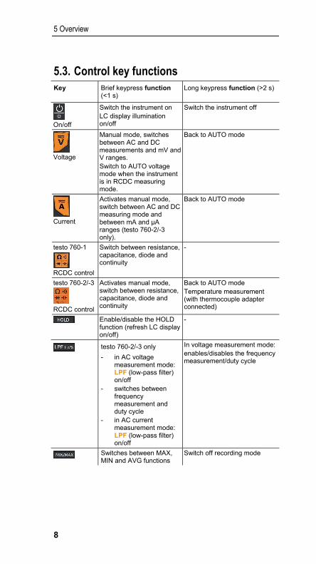
5.3. Control key functions Key Brief keypress function
(<1 s) Long keypress function (>2 s)
On/off
Switch the instrument on LC display illumination on/off
Switch the instrument off
Voltage
Manual mode, switches between AC and DC measurements and mV and V ranges. Switch to AUTO voltage mode when the instrument is in RCDC measuring mode.
Back to AUTO mode
Current
Activates manual mode, switch between AC and DC measuring mode and between mA and µA ranges (testo 760-2/-3 only).
Back to AUTO mode
testo 760-1
RCDC control
Switch between resistance, capacitance, diode and continuity
-
testo 760-2/-3
RCDC control
Activates manual mode, switch between resistance, capacitance, diode and continuity
Back to AUTO mode Temperature measurement (with thermocouple adapter connected)
Enable/disable the HOLD function (refresh LC display on/off)
-
testo 760-2/-3 only
- in AC voltage measurement mode: LPF (low-pass filter) on/off
- switches between frequency measurement and duty cycle
- in AC current measurement mode: LPF (low-pass filter) on/off
In voltage measurement mode: enables/disables the frequency measurement/duty cycle
Switches between MAX, MIN and AVG functions
Switch off recording mode

5 Overview
9
5.4. Further functions MAX/MIN/AVG
[ ] enables switching between maximum, minimum and the periodic display of AVG values. This function is disabled in the default setting.
> Activate function: press [ ] <1 s. - Max value is displayed. > Display min value and periodic display of AVG values:
press [ ] <1 s each time.
> Exit function: press [ ] >2 s or [ ].
This function can be activated in all measuring modes (this function is not available for frequency and capacitance measurement with testo 760-1).
When pressing [ ] in AUTO AC/DC voltage mode or AUTO AC/DC current measurement mode, the instrument retains the last-selected AC/DC setting. In all other operating modes, you can select what you need by briefly pressing the relevant keys themselves:
• Voltage measurement: press
• Current measurement: press • Resistance, continuity, diode and capacitance measurement:
press
• Frequency and duty cycle: press
HOLD
> Activate function: press [ ] <1 s. - the current reading is recorded and HOLD is shown on the LC display.
> Exit function: press [ ] <1 s. - the current measurement is displayed.
This function is available in all measuring modes.
LPF (low-pass filter) function (testo 760-2/3) The LPF function activates the low-pass filter (1 kHz). The low-pass filter can be activated during the AC voltage measurement mode and also during AC current measurement mode. It is switched off in the default setting.
> Activate LPF (low-pass filter): press [ ] <1 s. - The corresponding value is shown on the LC display.
5.5. Explanation of icons Icon Meaning
Attention! Warning about a danger spot, refer to instruction manual
Caution! Dangerous voltage, risk of electric shock
Application around and removal from HAZARDOUS LIVE conductors is permitted

6 Operating the instrument
10
Icon Meaning
Continuous double or reinforced insulation in accordance with category II DIN EN 61140/IEC 536
The product is certified for the US and Canadian markets, in accordance with the applicable American and Canadian standards.
Tested for safety (tested by TÜV Rheinland)
Compliance mark for ACMA (Australian Communications and Media Authority) guidelines.
This product has been tested to the requirements of CAN/CSA-C22.2 No. 61010-1, second edition, including Amendment 1, or a later version of the same standard incorporating the same level of testing requirements.
Conformity mark, verifies compliance with the valid EU Directives: EMC Directive (2014/30/EU) with the standard EN 61326-1, Low Voltage Directive (2014/35/EU) with the standard EN 61010 -2-33
The instrument complies with the WEEE Directive (2012/16/EU)
6 Operating the instrument
The instrument features technology that detects the plug position of the test leads and selects the measuring function based on that: - in voltage mode, the instrument automatically detects the relevant
measuring range and measurement type AC or DC. - in RCDC mode, the instrument automatically detects whether
resistance, capacitance, diode test and continuity need to be measured and adjusts the measuring range accordingly.
- in current mode, the instrument automatically detects the relevant measuring range as well as AC/DC, and differentiates between A and mA / µA measuring modes (automatic jack detection).
All the available measuring modes can also be selected manually.
Magnetic suspension system (accessory)
You can use the magnetic suspension system, which is available as an accessory, order number 0590 0001, to attach the testo 760 to metal surfaces. The suspension system’s magnet must not come anywhere near the battery compartment during the measurement (see graphic). Automatic adjustment of the measuring range could be influenced as a result.

6 Operating the instrument
11
WARNING
Magnetic field
May be harmful to those with pacemakers.
> Keep a minimum distance of 15 cm between pacemaker and instrument.
CAUTION
Magnetic field
Damage to other devices! > Keep a safe distance away from products that could be damaged by the effects of magnetism (e.g. monitors, computers or credit cards).
6.1. Switching the instrument on > To switch on: press the [ ] key for <1 s. - The instrument switches on.
6.2. Switching the background illumination on/off
> To switch on/off: briefly press the [ ] key. The background illumination switches off automatically within 1 minute.
It is possible to switch the background illumination on/off in all measuring modes.
6.3. Switching the instrument off (automatically/manually)
Automatically
The automatic power-off function (APO) is always enabled as a default setting and is shown on the LC display as APO. If no control key is pressed within 15 min, the instrument switches off automatically. If necessary, the automatic power-off function (APO) can be turned off.

7 Carrying out a measurement
12
> Disable power-off function: Before switching on the instrument, press
and hold down [ ] and then briefly press [ ]. Release the keys simultaneously.
- Power-off function is disabled.
Once the instrument has switched off, the power-off function is reset to the default setting.
Manually
> Switch the instrument off: press [ ] >2 s.
7 Carrying out a measurement
7.1. Preparing for measurement Prior to every test, please ensure that the instrument is in perfect condition: • For example, keep an eye out for broken housing or leaking batteries. • Always carry out a function test before using the instrument, see below. • Check that the instrument is functioning perfectly (for example at a
known voltage source) before and after every test. • If the safety of the user cannot be guaranteed, the instrument must be
switched off and secured to prevent unintentional usage.
When connecting the test leads to the test object, always connect the common test lead (COM) to the test object first of all. When disconnecting the test leads, always disconnect the test lead from the 10 A, V or mA jack (testo 760-2/-3) first of all.
Installing the probe tip protector The probe tip protector can be removed/installed as required. Attention: Use of the probe tip protector may be required depending on the national regulations or provisions! > Probe tip protector: push onto probe tips or pull off.
7.2. Voltage measurement Instrument is switched on.
When measuring AC voltage, the frequency is measured at the same time and shown in the relevant row on the LC display. .
Automatic measuring mode 1. Connect test leads: black test lead to the COM jack; red test lead to the
V/Ω/diode/capacitance jack.
The instrument features a built-in zero crossing detector. When the measured signal (voltage or current) indicates zero crossings, the instrument automatically switches to AC measuring mode. If no continuity is indicated, the instrument switches to DC measuring mode.
2. Connect test lead to the test object. - The measured value is shown on the LC display.

7 Carrying out a measurement
13
Manual measuring mode
Instrument is in AUTO V measuring mode.
1. Exit automatic measuring mode: press [ ] <1 s. - The instrument is in V AC mode.
2. Switch between V AC, V DC, mV AC and mV DC: press [ ] <1 s. - The measured value is shown on the LC display.
3. Switch to automatic measuring mode: press [ ] >1 s. - The instrument is in automatic measuring mode when AUTO appears
on the LC display.
7.3. Current measurement
7.3.1. testo 760-1
WARNING Serious risk of injury to the user and/or destruction of the instrument while measuring current. > Measuring circuit must be de-energized.
If fuses blow, please eliminate the cause of this before changing the fuse.
The measuring instrument may only be used in 16A fused electrical circuits up to a nominal voltage of 600V. The nominal cross-section of the connection cable must be taken into account in order to ensure safe connection (e.g. via crocodile clips).
Strong interferences in the vicinity result in an unstable display and measurement errors.
Instrument is switched on.
Automatic measuring mode 1. Connect test leads: black test lead to COM jack, red test lead to A jack. - The instrument is in AUTO A mode. 2. Connect test leads to the test object. - The measured value is shown on the LC display.
Manual measuring mode
Instrument is in AUTO A measuring mode.
1. Switch off automatic measuring mode: press [ ] <1 s.
2. Switch between A AC and A DC: press [ ] <1 s. - The measured value is shown on the LC display.
Switch to automatic measuring mode: press [ ] >1 s. - The instrument is in automatic measuring mode when AUTO is
illuminated on the LC display.

7 Carrying out a measurement
14
7.3.2. testo 760-2/-3
WARNING Serious risk of injury to the user and/or destruction of the instrument while measuring current. > Measuring circuit must be de-energized.
If fuses blow, please eliminate the cause of this before changing the fuse.
The measuring instrument may only be used in 16 A fused electrical circuits up to a nominal voltage of 600 V (760-2) / 1000 V (760-3). The nominal cross-section of the connection cable must be taken into account in order to ensure safe connection (e.g. via crocodile clips).
Strong interferences in the vicinity result in an unstable display and measurement errors.
7.3.2.1. 10 A jack
Instrument is switched on.
Automatic measuring mode 1. Connect test leads: black test lead to COM jack, red test lead to 10A
jack. - The instrument is in AUTO 10A mode. 2. Connect test leads to the test object. - The measured value is shown on the LC display.
Manual measuring mode
Instrument is in AUTO 10A measuring mode.
1. Switch off automatic measuring mode: press [ ] <1 s.
2. Switch between A AC and A DC: press [ ] <1 s. - The measured value is shown on the LC display.
Switch to automatic measuring mode: press [ ] >1 s. - The instrument is in automatic measuring mode when AUTO is
illuminated on the LC display.
7.3.2.2. µA/mA jack
Instrument is switched on.
Automatic measuring mode 1. Connect test leads: black test lead to COM jack, red test lead to
µA/mA jack. - The instrument is in AUTO µA/mA mode. 2. Connect test leads to the test object. - The measured value is shown on the LC display.
7 Carrying out a measurement
15
Manual measuring mode
Instrument is in AUTO µA/mA measuring mode.
1. Switch off automatic measuring mode: press [ ] <1 s.
2. Switch between mA AC, mA DC, µA AC, µA DC: press [ ] <1 s. - The measured value is shown on the LC display.
Switch to automatic measuring mode: press [ ] >1 s. - The instrument is in automatic measuring mode when AUTO is
illuminated on the LC display.
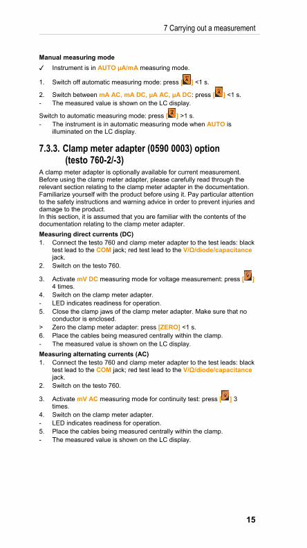
7.3.3. Clamp meter adapter (0590 0003) option (testo 760-2/-3)
A clamp meter adapter is optionally available for current measurement. Before using the clamp meter adapter, please carefully read through the relevant section relating to the clamp meter adapter in the documentation. Familiarize yourself with the product before using it. Pay particular attention to the safety instructions and warning advice in order to prevent injuries and damage to the product. In this section, it is assumed that you are familiar with the contents of the documentation relating to the clamp meter adapter.
Measuring direct currents (DC) 1. Connect the testo 760 and clamp meter adapter to the test leads: black
test lead to the COM jack; red test lead to the V/Ω/diode/capacitance jack.
2. Switch on the testo 760.
3. Activate mV DC measuring mode for voltage measurement: press [ ] 4 times.
4. Switch on the clamp meter adapter. - LED indicates readiness for operation. 5. Close the clamp jaws of the clamp meter adapter. Make sure that no
conductor is enclosed. > Zero the clamp meter adapter: press [ZERO] <1 s. 6. Place the cables being measured centrally within the clamp. - The measured value is shown on the LC display.
Measuring alternating currents (AC) 1. Connect the testo 760 and clamp meter adapter to the test leads: black
test lead to the COM jack; red test lead to the V/Ω/diode/capacitance jack.
2. Switch on the testo 760.
3. Activate mV AC measuring mode for continuity test: press [ ] 3 times.
4. Switch on the clamp meter adapter. - LED indicates readiness for operation. 5. Place the cables being measured centrally within the clamp. - The measured value is shown on the LC display.

7 Carrying out a measurement
16
7.4. Measuring resistance, capacitance, continuity and diode test
WARNING Serious risk of injury to the user and/or destruction of the instrument during resistance testing. > Test object must be de-energized.
External voltages will distort the measurement result.
You can use the magnetic suspension system, which is available as an accessory, order number 0590 0001, to attach the testo 760 to metal surfaces. The suspension system’s magnet must not come anywhere near the battery compartment during the measurement (see graphic). Automatic adjustment of the measuring range could be influenced as a result.
Resistors and semiconductors in parallel with the diode will distort the measurement result.
> Prior to the measurement, make sure that capacitors are discharged.
Instrument is switched on.
7.4.1. testo 760-1 Manual measuring mode 1. Connect test leads: black test lead to the COM jack; red test lead to the
V/Ω/diode/capacitance jack.
- The instrument is in Ω mode. 2. Switch between resistance, capacitance, continuity and diode test:
press [ ] <1 s. - The measured value is shown on the LC display.
7.4.2. testo 760-2/-3 Automatic measuring mode
Automatic detection for resistance/capacitance in the following range: • 0.0 ohms to 6.000 mohms • 0.500 nF to 600.0 µF Change to manual measuring mode for the remaining measuring range.
1. Connect test leads: black test lead to the COM jack; red test lead to the
V/Ω/diode/capacitance jack. - The instrument is in AUTO V mode.
2. Disable AUTO RCDC measuring mode: press [ ] <1 s.

7 Carrying out a measurement
17
3. Connect test leads to the test object. - The instrument detects resistance, continuity, diode and capacitance,
and automatically adjusts the measuring range. - The measured value is shown on the LC display.
Manual measuring mode (testo 760-2/-3)
1. Disable AUTO RCDC measuring mode: press [ ] <1 s. 2. Switch between resistance, capacitance, continuity and diode test:
press [ ] <1 s. - The measured value is shown on the LC display.
> Switch back to AUTO RCDC mode: press [ ] >2 s.
7.5. Frequency measurement (testo 760-1) Instrument is switched on.
1. Connect test leads: black test lead to the COM jack; red test lead to the V/Ω/diode/capacitance jack.
- The instrument is in AUTO V mode. 2. Activate measuring mode for frequency measurement: press [Hz] <1 s. 3. Connect test leads to the test object. - The measured value is shown on the LC display. > Switch back to AUTO V mode: press [Hz] <1 s.
7.6. Frequency measurement/duty cycle (testo 760-2/-3)
Instrument is switched on.
1. Connect test leads: black test lead to COM jack, red test lead to V/Ω/diode/capacitance jack.
- The instrument is in AUTO V mode 2. Activate measuring mode for frequency measurement: press [LPF
Hz/%] >2 s. 3. Activate the mode for duty cycle: press [LPF Hz/%] <1 s. 4. Connect test leads to the test object. - The measured value is shown on the LC display. > Switch back to AUTO V mode: press [LPF Hz/%] >2 s.
7.7. Temperature measurement (optional) (testo 760-2/-3)
A thermocouple adapter (0590 0002) is optionally available for measuring temperature. Before using the thermocouple adapter, please carefully read through the relevant section relating to the thermocouple adapter in the documentation. Familiarize yourself with the product before using it. Pay particular attention to the safety instructions and warning advice in order to prevent injuries and damage to the product. In this section, it is assumed that you are familiar with the contents of the documentation relating to the thermocouple adapter.
Taking temperature measurements A thermocouple is attached to the thermocouple adapter.
Instrument is switched on.

8 Service and maintenance
18
1. Connect the thermocouple adapter to the instrument: Insert the adapter into the COM jack and into the V/Ω/diode/capacitance. jack. Ensure correct polarity!
- The thermocouple adapter switches on automatically. - The instrument is in AUTO V mode. 2. Activate AUTO RCDC measuring mode for temperature
measurements: press [ ] >2 s. - The measured values are indicated in °C and °F on the LC display.
8 Service and maintenance
8.1. View of the back of the instrument
Screws 1 - 6: housing Screws 7 and 8: open the battery compartment
8.2. Replacing the batteries The batteries need to be replaced when the battery icon appears on the LC display. Instrument is switched off and de-energized. 1. Fully disconnect the instrument from the test leads. 2. Using a screwdriver, unscrew the two metal screws (7, 8) on the
battery compartment until the battery compartment cover can be removed. Do not unscrew the screws completely.
3. Remove the spent batteries. 4. Insert new batteries, type AAA / IEC LR03 (1.5 V), ensuring correct
polarity. 5. Put the battery compartment cover back on and screw down.

8 Service and maintenance
19
8.3. Changing the fuses Instrument is switched off and de-energized.
When opening/assembling the instrument, take care not to lose any of the removed screws. Placing a cloth on the work space is recommended.
1. Fully disconnect the instrument from the test leads. 2. Fold out the stand. 3. Undo and remove the screws (1 to 6) using a cross-head screwdriver. 4. Remove the lower section of the housing. 5. Remove the defective fuse from the fuse holder using an appropriate
fuse puller.
WARNING Serious risk of injury and destruction of the instrument due to makeshift fuses and short-circuiting of fuse holders. > Only use fuses with the voltage and current values listed under "Technical data".
6. Insert the new fuse into the fuse holder using the fuse puller. 7. Put the lower section of the housing on and screw on using the screws. 8. Fold in the stand.
8.4. Maintenance When operated in accordance with the instruction manual, the instrument does not require any particular maintenance. If a malfunction occurs during operation, the ongoing measurement should be stopped immediately. Send the instrument to Testo Service for checking.
8.5. Calibration In order to maintain the specified accuracy of the measurement results, Testo recommends calibrating the instrument once a year. Send the instrument to Testo-Industrial-Services GmbH for calibration.
8.6. Storage - Store the instrument in dry, closed rooms. > If the instrument is not in use for a significant period of time: remove
the batteries in order to prevent any danger or damage due to any potential leaking of the batteries.
8.7. Cleaning Before cleaning, the instrument must be switched off and disconnected from external voltages or from other connected instruments (test specimen, control units, etc.). > Wipe the instrument with a damp cloth and a small amount of mild
household detergent. Never use any harsh cleaning agents or solvents to clean the instrument! After being cleaned, the instrument must not be used until it has completely dried.
9 Technical data
20
9 Technical data
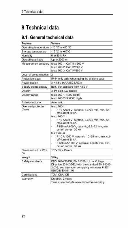
9.1. General technical data Feature Values
Operating temperature -10 °C to +50 °C
Storage temperature -15 °C to +60°C
Humidity 0 to 80% RH
Operating altitude Up to 2000 m
Measurement category testo 760-1: CAT III / 600 V testo 760-2: CAT IV/600 V testo 760-3: CAT IV/600 V
Level of contamination 2
Protection class IP 64 only valid when using the silicone caps
Power supply 3 × 1.5V (AAA/IEC LR03)
Battery status display Batt. icon appears from <3.9 V
Display 3 3/4 digit, LC display
Display range testo 760-1: 4000 digits) testo 760-2/-3: 6000 digits
Polarity indicator Automatic
Overload protection (fuse)
testo 760-1: - F 10 A/600 V, ceramic, 6.3×32 mm, min. cut-
off current 20 kA testo 760-2: - F 10 A/600 V, ceramic, 6.3×32 mm, min. cut-
off current 30 kA - F 630 mA/600 V, ceramic, 6.3×32 mm, min.
cut-off current 30 kA testo 760-3: - F 10 A/1000 V, ceramic, 10×38 mm, min. cut-
off current 30 kA - F 630 mA/1000 V, ceramic, 6.3×32 mm, min.
cut-off current 30 kA
Dimensions (H x W x D)
167x 85 x 45 mm
Weight 340 g
Safety standards EMV 2014/30/EU, EN 61326-1, Low Voltage Directive 2014/35/EU with the standard EN 61010-2-033, and insulation complying with class II IEC 536/DIN EN 61140
Certifications TÜV, CSA, CE
Warranty Duration: 2 years Terms: see website www.testo.com/warranty
9 Technical data
21
9.2. More technical data
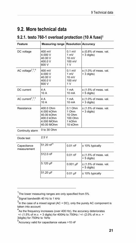
9.2.1. testo 760-1 overload protection (10 A fuse)1 Feature Measuring range Resolution Accuracy
DC voltage 400 mV 4.000 V 40.00 V 400.0 V 600 V
0.1 mV 1 mV 10 mV 100 mV 1 V
± (0.8% of meas. val. + 3 digits)
AC voltage2,3,4 400 mV 4.000 V 40.00 V 400.0 V 600 V
0.1 mV 1 mV 10 mV 100 mV 1 V
± (1.0% of meas. val. + 3 digits)
DC current 4 A 10 A
1 mA 10 mA
± (1.5% of meas. val. + 5 digits)
AC current2,3,4 4 A 10 A
1 mA 10 mA
± (1.0% of meas. val. + 3 digits)
Resistance 400.0 Ohm 4.000 kOhm 40.00 kOhm 400.0 kOhm 4.000 MOhm 40.00 MOhm
0.1 Ohm 1 Ohm 10 Ohm 100 Ohm1 kOhm 10 kOhm
± (1.5% of meas. val. + 3 digits)
Continuity alarm 0 to 30 Ohm
Diode test 2.5 V
Capacitance measurement
51.20 nF5 0.01 nF ± 10% typically
512.0 nF 0.01 nF ± (1.5% of meas. val. + 5 digits)
5.120 µF 0.001 µF ± (1.5% of meas. val. + 5 digits)
51.20 µF 0.01 µF ± 10% typically
1The lower measuring ranges are only specified from 5%
2Signal bandwidth 40 Hz to 1 kHz
3In the case of a mixed signal (AC + DC), only the purely AC component is
taken into account 4As the frequency increases (over 400 Hz), the accuracy deteriorates
+/- (1.5% of m.v. + 3 digits) for 400Hz to 750Hz / +/- (2.0% of m.v. + 3digits) for 750Hz to 1kHz 5Accuracy valid for capacitance values >10 nF

9 Technical data
22
Feature Measuring range Resolution Accuracy
100.0 µF6 0.1 µF ± 10% typically
Frequency measurement7,8
5.120 Hz 51.20 Hz 512.0 Hz 5.120 kHz 51.20 kHz 512.0 kHz
0.001 Hz 0.01 Hz 0.1 Hz 1 Hz 10 Hz 100 Hz
± (0.1% + 1 digit)
Frequency with voltage/current9
99.99 Hz 999.9 Hz 9.999 kHz
0.01 Hz 0.1 Hz 1 Hz
± (0.1% + 1 digit)
Figures correspond to +23 °C ± 5 °C at <80% rel. humidity. Temperature coefficient: 0.15 x specified accuracy per 1 °C (<18 °C and >28 °C)
9.2.2. testo 760-2/-3 Overload protection (10 A fuse)10
Feature Measuring range
Resolution Accuracy
DC voltage 600 mV 6.000 V 60.00 V 600.0 V 1000 V (760-3)
0.1 mV 1 mV 10 mV 100 mV 1 V (760-3)
± (0.8% of meas. val. + 3 digits)
AC voltage11,12,13 600 mV 6.000 V 60.00 V 600.0 V 1000 V (760-3)
0.1 mV 1 mV 10 mV 100 mV 1 V (760-3)
± (1.0% of meas. val. + 3 digits)
6Maximum measurement duration is 15 s
7Frequency measurement as separate function
8Below 2 Hz the display shows 0 Hz
9Frequency measurement is not specified for alternating currents or
voltages below 3% of the smallest respective measuring range 10
The lower measuring ranges are only specified from 5% 11
Signal bandwidth 40 Hz to 1 kHz 12
In the case of a mixed signal (AC + DC), only the purely AC component is taken into account 13
As the frequency increases (over 400 Hz), the accuracy deteriorates +/- (1.5% of m.v. + 3 digits) for 400Hz to 750Hz / +/- (2.0% of m.v. + 3digits) for 750Hz to 1kHz

9 Technical data
23
Feature Measuring range
Resolution Accuracy
DC current 600 μA 6000 μA 60.00 mA 600.0 mA 6 A 10 A
0.1 μA 1 μA 10 μA 100 μA 1 mA 10 mA
± (1.5% of meas. val. + 5 digits)
AC current11,12,13 600 μA 6000 μA 60.00 mA 600.0 mA 6 A 10 A
0.1 μA 1 μA 10 μA 100 μA 1 mA 10 mA
± (1.5% of meas. val. + 5 digits)
Resistance 60.00 Ohm 600.0 Ohm 6.000 kOhm 60.00 kOhm 600.0 kOhm 6.000 MOhm60.00 MOhm
0.01 Ohm 0.1 Ohm 1 Ohm 10 Ohm 100 Ohm 1 kOhm 10 kOhm
± (1.5% of meas. val. + 3 digits)
Continuity alarm 0 to 30 Ohm
Diode test 2.5 V
Low-pass filter yes (1 kHz)
Duty cycle14 20 Hz to 1 kHz ± 1% + 3 digits
1 kHz to 10 kHz ± 5% + 3 digits
Capacitance measurement
6.000 nF15 0.001 nF ± (10 % of meas. val. + 25 digits)
60.00 nF 0.01 nF ± (2% of meas. val. + 10 digits)
600.0 nF 0.1 nF ± (1.5% of meas. val. + 5 digits)
6.000 µF 0.001 µF ± (1.5% of meas. val. + 5 digits)
60.00 µF 0.01 µF ± (1.5% of meas. val. + 5 digits)
600.0 µF 0.1 µF ± (2% of meas. val. + 10 digits)
6.000 mF 1 µF ± 10% typically
60.00 mF16 10 µF ± 10% typically
14
Pulse width is measured in the range 5% to 95% (f<10 kHz@3Vpp) 15
Accuracy valid for capacitance values > 2 nF

10 Tips and assistance
24
Feature Measuring range
Resolution Accuracy
Frequency measurement17,18
600.0 Hz 6.000 kHz 60.00 kHz 600.0 kHz 6.000 MHz 60.00 MHz
0.1 Hz 1 Hz 10 Hz 100 Hz 1 kHz 10 kHz
± (0.1% + 1 digits)
Frequency with voltage/current19
99.99 Hz 999.9 Hz 9.999 kHz
0.01 Hz 0.1 Hz 1 Hz
± (0.1% + 1 digits)
Temperature with adapter20
-20 to 500 °C
0.2 °C -20 to 0 °C ± 2 °C 0 to 99.99 °C ± 1 °C 100 to 249.99 °C ± 1.5%>250 °C ± 2%
Current with adapter21
400 A 0.1 A ± (2% of meas. val. + 5 digits)
Figures correspond to +23 °C ± 5 °C at <80% rel. humidity. Temperature coefficient: 0.15 x specified accuracy per 1 °C (<18 °C and >28 °C)
10 Tips and assistance
10.1. Questions and answers
Question Possible causes/solution
OL The reading exceeds the measuring range upper limit > Check input value and change if necessary.
LEAd No probe tip in the jack or invalid arrangement with warning to the user > Connect missing probe tip. > Check arrangement and correct if necessary.
dISC The capacitor to be tested still contains charge. > Discharge capacitor properly and carry out the test again.
OPEn No connection to the probe tips during the RCDC measuring mode. > Establish a connection to the measurement object.
16
Maximum measurement duration is 13.2 s 17
Frequency measurement as separate function 18
Below 2 Hz the display shows 0 Hz 19
Frequency measurement is not specified for alternating currents or voltages below 3% of the smallest respective measuring range 20
Does not include the measurement error of the temperature probe. The specified accuracy is the sum total of the measurement errors of the thermocouple adapter and the instrument. 21
The specified accuracy does not include the measurement error of the instrument

11 Protecting the environment
25
Question Possible causes/solution
Defective fuse indication
If a fuse for the A (testo 760-1, mA and/or 10A (testo 760-2/-3) jack is defective, the instrument will no longer detect the corresponding jack. Instrument will not switch to A-mode. > Replace defective fuse.
If we have not been able to answer your question, please contact your dealer or Testo Customer Service. For contact details, please visit www.testo.com/service-contact.
10.2. Accessories and spare parts
Probe and other assemblies are appropriately rated for measurement category III or IV and have a suitable voltage rating for the circuit to be measured.
11 Protecting the environment
> Dispose of faulty rechargeable batteries/spent batteries in accordance with the valid legal specifications.
> At the end of its useful life, send the product to the separate collection for electric and electronic devices (observe local regulations) or return the product to Testo for disposal.
> The button cell used in the instrument contains 1,2-Dimethoxyethane (CAS 110-71-4). See EC Regulation No. 1907/2006 (REACH) Art. 33.

0970 7600 en 03