TESTING TX-D RELAYS - panasonic-electric-works.com€¦ · Several part numbers will be...
12
TX-D Several part numbers will be discontinued September 30, 2013. 1 ds_61022_en_txd: 150113D High breakdown voltage type is available (1.5 kV between open contacts) TX-D RELAYS TESTING Several part numbers will be discontinued September 30, 2013. Several part numbers will be discontinued September 30, 2013. FEATURES 1. Lineup now includes high breakdown voltage type that achieves breakdown voltage between open contacts of 1,500 V AC. Surge breakdown voltage between open contacts: 1,500 V 10 160 sec. (FCC part 68) Surge breakdown voltage between contact and coil: 6,000 V 1.2 50 sec. (EN60950) 2. Approved to the supplementary insulation class in the EN standards (EN60950). The insulation distance between the contact and coil meet the supplementary insulation class of the EN60950 standards as required for equipment connected to the telephone lines in Europe. Satisfies the following conditions: • Clearances: 2.0 mm .079 inch or more • Creepage distance: 2.5 mm .098 inch or more 3. 3,000 V breakdown voltage between contact and coil. (Surge breakdown voltage 6,000 V type) The body block construction of the coil that is sealed formation offers a high breakdown voltage of 3,000 V between contact and coil. 4. Nominal operating power: High sensitivity of 200 mW By using the highly efficient polar magnetic circuit “seesaw balance mechanism”, a nominal operating power of 200 mW has been achieved. 5. High contact capacity: 2 A 30 V DC 6. High contact reliability achieved with gold-clad crossbar twin contacts and the use of gas expelling materials during formation. *We also offer TX-series relays with AgPd contacts, suitable for use in low level load analog circuits. 7. Outstanding vibration and shock resistance. Functional shock resistance: 750 m/s 2 Destructive shock resistance: 1,000 m/s 2 Functional vibration resistance: 10 to 55 Hz (at double amplitude of 3.3 mm .130 inch) Destructive vibration resistance: 10 to 55 Hz (at double amplitude of 5 mm .197 inch) 8. Sealed construction allows automatic washing. 9. A range of surface-mount types is also available. SA: Low-profile surface-mount terminal type SS: Space saving surface-mount terminal type 10. M.B.B. type available (Surge breakdown voltage 2,500 V type only) TYPICAL APPLICATIONS 1. Facsimile 2. Modem 3. Communications (xDSL) 4. Medical equipment 5. Automotive equipment 6. Security
-
Upload
vuongkhuong -
Category
Documents
-
view
216 -
download
0
Transcript of TESTING TX-D RELAYS - panasonic-electric-works.com€¦ · Several part numbers will be...

TX-DSeveral part numbers will be discontinued September 30, 2013.
1ds_61022_en_txd: 150113D
High breakdown voltage typeis available (1.5 kV between
open contacts)TX-D RELAYS
TESTINGSeveral part numbers will be discontinued September 30, 2013.
Several part numbers will be discontinued September 30, 2013.
FEATURES1. Lineup now includes high
breakdown voltage type that achieves breakdown voltage between open contacts of 1,500 V AC.Surge breakdown voltage between open contacts:1,500 V 10 160 sec. (FCC part 68)Surge breakdown voltage between contact and coil:6,000 V 1.2 50 sec. (EN60950)
2. Approved to the supplementary insulation class in the EN standards (EN60950).The insulation distance between the contact and coil meet the supplementary insulation class of the EN60950 standards as required for equipment connected to the telephone lines in Europe.Satisfies the following conditions:• Clearances: 2.0 mm .079 inch or
more• Creepage distance: 2.5 mm .098 inch
or more
3. 3,000 V breakdown voltage between contact and coil. (Surge breakdown voltage 6,000 V type)The body block construction of the coil that is sealed formation offers a high breakdown voltage of 3,000 V between contact and coil.
4. Nominal operating power: High sensitivity of 200 mWBy using the highly efficient polar magnetic circuit “seesaw balance mechanism”, a nominal operating power of 200 mW has been achieved.
5. High contact capacity: 2 A 30 V DC6. High contact reliability achieved
with gold-clad crossbar twin contacts and the use of gas expelling materials during formation.*We also offer TX-series relays with AgPd contacts, suitable for use in low level load analog circuits.
7. Outstanding vibration and shock resistance.Functional shock resistance: 750 m/s2
Destructive shock resistance: 1,000 m/s2
Functional vibration resistance: 10 to 55 Hz (at double amplitude of 3.3 mm .130 inch)Destructive vibration resistance: 10 to 55 Hz (at double amplitude of 5 mm .197 inch)
8. Sealed construction allows automatic washing.
9. A range of surface-mount types is also available.SA: Low-profile surface-mount terminal typeSS: Space saving surface-mount terminal type
10. M.B.B. type available (Surge breakdown voltage 2,500 V type only)
TYPICAL APPLICATIONS1. Facsimile2. Modem3. Communications (xDSL)4. Medical equipment5. Automotive equipment6. Security

TX-D Several part numbers will be discontinued September 30, 2013.
2 ds_61022_en_txd: 150113D
ORDERING INFORMATION
Several part numbers will be discontinued September 30, 2013.
TYPES1. Standard (B.B.M.) type/Surge breakdown voltage (between contact and coil) 2,500 V/ Breakdown voltage (between open contacts) 1,000 V1) Standard PC board terminal
Standard packing: Tube: 40 pcs.; Case: 1,000 pcs.Note: Please add “-1” to the end of the part number for AgPd contacts (low level load).
2) Surface-mount terminal(1) Tube packing
: For each surface-mount terminal identification, input the following letter. SA type: A, SS type: SStandard packing: Tube: 40 pcs.; Case: 1,000 pcs.Note: Please add “-1” to the end of the part number for AgPd contacts (low level load).
Contact arrangement
Nominal coil voltage
Single side stable 1 coil latching
Part No. Part No.
2 Form C
1.5V DC TXD2-1.5V TXD2-L-1.5V
3V DC TXD2-3V TXD2-L-3V
4.5V DC TXD2-4.5V TXD2-L-4.5V
5V DC TXD2-5V TXD2-L-5V
6V DC TXD2-6V TXD2-L-6V
9V DC TXD2-9V TXD2-L-9V
12V DC TXD2-12V TXD2-L-12V
24V DC TXD2-24V TXD2-L-24V
Contact arrangement
Nominal coil voltage
Single side stable 1 coil latching
Part No. Part No.
2 Form C
1.5V DC TXD2S-1.5V TXD2S-L-1.5V
3V DC TXD2S-3V TXD2S-L-3V
4.5V DC TXD2S-4.5V TXD2S-L-4.5V
5V DC TXD2S-5V TXD2S-L-5V
6V DC TXD2S-6V TXD2S-L-6V
9V DC TXD2S-9V TXD2S-L-9V
12V DC TXD2S-12V TXD2S-L-12V
24V DC TXD2S-24V TXD2S-L-24V
Nominal coil voltage (DC)1.5, 3, 4.5, 5, 6, 9, 12, 24V
Contact arrangement2: 2 Form C
TXD 2
Terminal shapeNil: Standard PC board terminal or surface-mount terminal
Type of operationNil:2M:
Standard typeM.B.B. type (Surge breakdown voltage 2,500 V and Single side stable type only)
Contact material/Surge breakdown voltage (between contact and coil)/Breakdown (between open contacts)Nil:1:3:4:6:7:
Standard contact (Ag+Au clad), 2,500 V/1,000 VAgPd contact (low level load); AgPd+Au clad (stationary), AgPd (movable), 2,500 V/1,000 VStandard contact (Ag+Au clad), 6,000 V/1,500 VAgPd contact (low level load); AgPd+Au clad (stationary), AgPd (movable), 6,000 V/1,500 VStandard contact (Ag+Au clad ), 6,000 V/1,000 VAgPd contact (low level load); AgPd+Au clad (stationary), AgPd (movable), 6,000 V/1,000 V
Operating functionNil: Single side stable L: 1 coil latching
Surface-mount availabilityNil: SA: SA type SS: SS type
Standard PC board terminal
Packing styleNil:X:Z:
Tube packingTape and reel (picked from 1/3/4/5-pin side)Tape and reel packing (Picked from the 8/9/10/12-pin side)
Note: In case of 5 V transistor drive circuit, it is recommended to use 4.5 V type relay.
(Discontinued Sept. 30, 2013)

TX-DSeveral part numbers will be discontinued September 30, 2013.
3ds_61022_en_txd: 150113D
(2) Tape and reel packing
: For each surface-mount terminal identification, input the following letter. SA type: A, SS type: SStandard packing: Tape and reel: 500 pcs.; Case: 1,000 pcs.Notes: 1. Tape and reel packing symbol “-Z” is not marked on the relay. “X” type tape and reel packing (picked from 1/3/4/5-pin side) is also available.
2. Please add “-1” to the part number for AgPd contacts (low level load). (Ex. TXD2SA-1.5V-1-Z)
2. M.B.B type/Surge breakdown voltage (between contact and coil) 2,500 V/ Breakdown voltage (between open contacts) 1,000 V1) Standard PC board terminal
Standard packing: Tube: 40 pcs.; Case: 1,000 pcs.
2) Surface-mount terminal(1) Tube packing
: For each surface-mount terminal identification, input the following letter. SA type: A, SS type: SStandard packing: Tube: 40 pcs.; Case: 1,000 pcs.
(2) Tape and reel packing
: For each surface-mount terminal identification, input the following letter. SA type: A, SS type: SStandard packing: Tape and reel: 500 pcs.; Case: 1,000 pcs.Notes: 1. Types designed to withstand strong vibration caused, for example, by the use of terminal cutters, can also be ordered.
However, please contact us if you need parts for use in low level load. (Ex. TXD2SA-2M-1.5V-1-Z)2. Tape and reel packing symbol “-Z” is not marked on the relay. “X” type tape and reel packing (picked from 1/3/4/5-pin side) is also available.
Contact arrangement
Nominal coil voltage
Single side stable 1 coil latching
Part No. Part No.
2 Form C
1.5V DC TXD2S-1.5V-Z TXD2S-L-1.5V-Z
3V DC TXD2S-3V-Z TXD2S-L-3V-Z
4.5V DC TXD2S-4.5V-Z TXD2S-L-4.5V-Z
5V DC TXD2S-5V-Z TXD2S-L-5V-Z
6V DC TXD2S-6V-Z TXD2S-L-6V-Z
9V DC TXD2S-9V-Z TXD2S-L-9V-Z
12V DC TXD2S-12V-Z TXD2S-L-12V-Z
24V DC TXD2S-24V-Z TXD2S-L-24V-Z
Contact arrangement Nominal coil voltageSingle side stable
Part No.
2 Form C
1.5V DC TXD2-2M-1.5V
3V DC TXD2-2M-3V
4.5V DC TXD2-2M-4.5V
5V DC TXD2-2M-5V
6V DC TXD2-2M-6V
9V DC TXD2-2M-9V
12V DC TXD2-2M-12V
24V DC TXD2-2M-24V
Contact arrangement Nominal coil voltageSingle side stable
Part No.
2 Form C
1.5V DC TXD2S-2M-1.5V
3V DC TXD2S-2M-3V
4.5V DC TXD2S-2M-4.5V
5V DC TXD2S-2M-5V
6V DC TXD2S-2M-6V
9V DC TXD2S-2M-9V
12V DC TXD2S-2M-12V
24V DC TXD2S-2M-24V
Contact arrangement Nominal coil voltageSingle side stable
Part No.
2 Form C
1.5V DC TXD2S-2M-1.5V-Z
3V DC TXD2S-2M-3V-Z
4.5V DC TXD2S-2M-4.5V-Z
5V DC TXD2S-2M-5V-Z
6V DC TXD2S-2M-6V-Z
9V DC TXD2S-2M-9V-Z
12V DC TXD2S-2M-12V-Z
24V DC TXD2S-2M-24V-Z

TX-D Several part numbers will be discontinued September 30, 2013.
4 ds_61022_en_txd: 150113D
3. Standard (B.B.M.) type/Surge breakdown voltage (between contact and coil) 6,000 V/ Breakdown voltage (between open contacts) 1,000 V1) Standard PC board terminal
Standard packing: Tube: 40 pcs.; Case: 1,000 pcs.Note: Please add “-7” to the end of the part number for AgPd contacts (low level load).
2) Surface-mount terminal(1) Tube packing
: For each surface-mount terminal identification, input the following letter. SA type: A, SS type: SStandard packing: Tube: 40 pcs.; Case: 1,000 pcs.Note: Please add “-7” to the end of the part number for AgPd contacts (low level load).
(2) Tape and reel packing
: For each surface-mount terminal identification, input the following letter. SA type: A, SS type: SStandard packing: Tape and reel: 500 pcs.; Case: 1,000 pcs.Notes: 1. Tape and reel packing symbol “-Z” is not marked on the relay. “X” type tape and reel packing (picked from 1/3/4/5-pin side) is also available.
2. Please add “-7” to the part number for AgPd contacts (low level load). (Ex. TXD2SA-1.5V-7-Z)
Contact arrangement
Nominal coil voltage
Single side stable 1 coil latching
Part No. Part No.
2 Form C
1.5V DC TXD2-1.5V-6 TXD2-L-1.5V-6
3V DC TXD2-3V-6 TXD2-L-3V-6
4.5V DC TXD2-4.5V-6 TXD2-L-4.5V-6
5V DC TXD2-5V-6 TXD2-L-5V-6
6V DC TXD2-6V-6 TXD2-L-6V-6
9V DC TXD2-9V-6 TXD2-L-9V-6
12V DC TXD2-12V-6 TXD2-L-12V-6
24V DC TXD2-24V-6 TXD2-L-24V-6
Contact arrangement
Nominal coil voltage
Single side stable 1 coil latching
Part No. Part No.
2 Form C
1.5V DC TXD2S-1.5V-6 TXD2S-L-1.5V-6
3V DC TXD2S-3V-6 TXD2S-L-3V-6
4.5V DC TXD2S-4.5V-6 TXD2S-L-4.5V-6
5V DC TXD2S-5V-6 TXD2S-L-5V-6
6V DC TXD2S-6V-6 TXD2S-L-6V-6
9V DC TXD2S-9V-6 TXD2S-L-9V-6
12V DC TXD2S-12V-6 TXD2S-L-12V-6
24V DC TXD2S-24V-6 TXD2S-L-24V-6
Contact arrangement
Nominal coil voltage
Single side stable 1 coil latching
Part No. Part No.
2 Form C
1.5V DC TXD2S-1.5V-6-Z TXD2S-L-1.5V-6-Z
3V DC TXD2S-3V-6-Z TXD2S-L-3V-6-Z
4.5V DC TXD2S-4.5V-6-Z TXD2S-L-4.5V-6-Z
5V DC TXD2S-5V-6-Z TXD2S-L-5V-6-Z
6V DC TXD2S-6V-6-Z TXD2S-L-6V-6-Z
9V DC TXD2S-9V-6-Z TXD2S-L-9V-6-Z
12V DC TXD2S-12V-6-Z TXD2S-L-12V-6-Z
24V DC TXD2S-24V-6-Z TXD2S-L-24V-6-Z

TX-DSeveral part numbers will be discontinued September 30, 2013.
5ds_61022_en_txd: 150113D
4. Standard (B.B.M.) type/Surge breakdown voltage (between contact and coil) 6,000 V/ Breakdown voltage (between open contacts) 1,500 V (High breakdown voltage type)1) Standard PC board terminal
Standard packing: Tube: 40 pcs.; Case: 800 pcs.Note: Please add “-4” to the end of the part number for AgPd contacts (low level load).
2) Surface-mount terminal(1) Tube packing
: For each surface-mount terminal identification, input the following letter. SA type: A, SS type: SStandard packing: Tube: 40 pcs.; Case: 800 pcs.Note: Please add “-4” to the end of the part number for AgPd contacts (low level load).
(2) Tape and reel packing
*Only for SA type.Standard packing: Tape and reel: 500 pcs.; Case: 1,000 pcs.Notes: 1. Tape and reel packing symbol “-Z” is not marked on the relay. “X” type tape and reel packing (picked from 1/3/4/5-pin side) is also available.
2. Please add “-4” to the part number for AgPd contacts (low level load). (Ex. TXD2SA-1.5V-4-Z)
Contact arrangement
Nominal coil voltage
Single side stable 1 coil latching
Part No. Part No.
2 Form C
1.5V DC TXD2-1.5V-3 TXD2-L-1.5V-3
3V DC TXD2-3V-3 TXD2-L-3V-3
4.5V DC TXD2-4.5V-3 TXD2-L-4.5V-3
5V DC TXD2-5V-3 TXD2-L-5V-3
6V DC TXD2-6V-3 TXD2-L-6V-3
9V DC TXD2-9V-3 TXD2-L-9V-3
12V DC TXD2-12V-3 TXD2-L-12V-3
24V DC TXD2-24V-3 TXD2-L-24V-3
Contact arrangement
Nominal coil voltage
Single side stable 1 coil latching
Part No. Part No.
2 Form C
1.5V DC TXD2S-1.5V-3 TXD2S-L-1.5V-3
3V DC TXD2S-3V-3 TXD2S-L-3V-3
4.5V DC TXD2S-4.5V-3 TXD2S-L-4.5V-3
5V DC TXD2S-5V-3 TXD2S-L-5V-3
6V DC TXD2S-6V-3 TXD2S-L-6V-3
9V DC TXD2S-9V-3 TXD2S-L-9V-3
12V DC TXD2S-12V-3 TXD2S-L-12V-3
24V DC TXD2S-24V-3 TXD2S-L-24V-3
Contact arrangement
Nominal coil voltage
Single side stable 1 coil latching
Part No. Part No.
2 Form C
1.5V DC TXD2SA-1.5V-3-Z TXD2SA-L-1.5V-3-Z
3V DC TXD2SA-3V-3-Z TXD2SA-L-3V-3-Z
4.5V DC TXD2SA-4.5V-3-Z TXD2SA-L-4.5V-3-Z
5V DC TXD2SA-5V-3-Z TXD2SA-L-5V-3-Z
6V DC TXD2SA-6V-3-Z TXD2SA-L-6V-3-Z
9V DC TXD2SA-9V-3-Z TXD2SA-L-9V-3-Z
12V DC TXD2SA-12V-3-Z TXD2SA-L-12V-3-Z
24V DC TXD2SA-24V-3-Z TXD2SA-L-24V-3-Z

TX-D Several part numbers will be discontinued September 30, 2013.
6 ds_61022_en_txd: 150113D
RATING1. Coil data[Standard (B.B.M.) type]1) Single side stable
2) 1 coil latching
[M.B.B. type]
*Pulse drive (JIS C 5442-1986)*Only for surge breakdown voltage of 2,500 V.
Nominal coil voltage
Pick-up voltage
(at 20C 68F)
Drop-out voltage
(at 20C 68F)
Nominal operating current [10%] (at 20C 68F)
Coil resistance [10%] (at 20C 68F)
Nominal operating power
Max. applied voltage
(at 20C 68F)
Surge breakdown
voltage: 2,500V/
6,000 V
Surge breakdown
voltage: 6,000 V (High
breakdown voltage)
Surge breakdown
voltage: 2,500V/
6,000 V
Surge breakdown
voltage: 6,000 V (High
breakdown voltage)
Surge breakdown
voltage: 2,500V/
6,000 V
Surge breakdown
voltage: 6,000 V (High
breakdown voltage)
1.5V DC
75%V or less of nominal voltage* (Initial)
10%V or more of nominal voltage* (Initial)
132.7mA 187.5mA 11 8
200mW 280mW 120%V of nominal voltage
3V DC 66.7mA 93.5mA 45 32
4.5V DC 44.4mA 62.5mA 101 72
5V DC 40.0mA 56.2mA 125 89
6V DC 33.3mA 46.5mA 180 129
9V DC 22.2mA 31.1mA 405 289
12V DC 16.7mA 23.3mA 720 514
24V DC 9.6mA 12.9mA 2,504 1,858 230mW 310mW
Nominal coil voltage
Set voltage (at 20C 68F)
Reset voltage (at 20C 68F)
Nominal operating current [10%] (at 20C 68F)
Coil resistance [10%] (at 20C 68F)
Nominal operating power
Max. applied voltage
(at 20C 68F)
Surge breakdown
voltage: 2,500V/
6,000 V
Surge breakdown
voltage: 6,000 V (High
breakdown voltage)
Surge breakdown
voltage: 2,500V/
6,000 V
Surge breakdown
voltage: 6,000 V (High
breakdown voltage)
Surge breakdown
voltage: 2,500V/
6,000 V
Surge breakdown
voltage: 6,000 V (High
breakdown voltage)
1.5V DC
75%V or less of nominal voltage* (Initial)
75%V or less of nominal voltage* (Initial)
100.0mA 153.1mA 15 10
150mW 230mW 120%V of nominal voltage
3V DC 50.0mA 76.9mA 60 39
4.5V DC 33.3mA 51.1mA 135 88
5V DC 30.0mA 46.3mA 166 109
6V DC 25.0mA 38.5mA 240 156
9V DC 16.7mA 25.6mA 540 352
12V DC 12.5mA 19.2mA 960 626
24V DC 7.1mA 10.4mA 3,388 2,304 170mW 250mW
Nominal coil voltage
Pick-up voltage (at 20C 68F)
Drop-out voltage (at 20C 68F)
Nominal operating current
[10%] (at 20C 68F)
Coil resistance [10%] (at 20C 68F)
Nominal operating power
Max. applied voltage (at 20C 68F)
1.5V DC
75%V or less of nominal voltage*
(Initial)
10%V or more of nominal voltage*
(Initial)
166.7mA 9
250mW 120%V of nominal voltage
3V DC 83.3mA 36
4.5V DC 55.6mA 81
5V DC 50.0mA 100
6V DC 41.7mA 144
9V DC 27.8mA 324
12V DC 20.8mA 576
24V DC 11.3mA 2,133 270mW

TX-DSeveral part numbers will be discontinued September 30, 2013.
7ds_61022_en_txd: 150113D
2. SpecificationsCharacteristics Item Specifications
Contact
Arrangement 2 Form C 2 Form D (M.B.B.type)*1
*1 M.B.B. type models are only available in 2,500 V surge breakdown voltage type.
Contact resistance (Initial) Max. 100 m (By voltage drop 6 V DC 1A)
Contact materialStandard contact: Ag+Au clad,
AgPd contact (low level load): AgPd+Au clad (stationary), AgPd (movable)
Rating
Nominal switching capacityStandard contact: 2 A 30 V DC,
AgPd contact: 1 A 30 V DC (resistive load)1 A 30 V DC (resistive load)
Max. switching powerStandard contact: 60 W (DC),
AgPd contact: 30 W (DC) (resistive load)30 W (DC) (resistive load)
Max. switching voltage 220 V DC 110 V DC
Max. switching current Standard contact: 2 A, AgPd contact: 1 A 1 A
Min. switching capacity (Reference value)*2
*2 This value can change due to the switching frequency, environmental conditions, and desired reliability level, therefore it is recommended to check this with the actual load. (AgPd contact type is available for low level load switching.)
10A10mV DC
Nominal operating power
Single side stable
Surge breakdown voltage 2,500 V and 6,000 V types:
200mW (1.5 to 12 V DC), 230mW (24 V DC)Surge breakdown voltage
6,000 V (High breakdown voltage) type: 280mW (1.5 to 12 V DC), 310mW (24 V DC)
250mW (1.5 to 12 V DC), 270mW (24 V DC)
1 coil latching
Surge breakdown voltage 2,500 V and 6,000 V types:
150mW (1.5 to 12 V DC), 170mW (24 V DC)Surge breakdown voltage
6,000 V (High breakdown voltage) type: 230mW (1.5 to 12 V DC), 250mW (24 V DC)
—
Electrical characteristics
Insulation resistance (Initial) Min. 1,000M (at 500V DC) Measurement at same location as “Initial breakdown voltage” section.
Breakdown voltage (Initial)
Between open contacts
Surge breakdown voltage 2,500 V and 6,000 V types:
1,000 Vrms for 1min. (Detection current: 10mA)Surge breakdown voltage
6,000 V (High breakdown voltage) type: 1,500 Vrms for 1min. (Detection current: 10mA)
500 Vrms for 1min. (Detection current: 10mA)
Between contact and coil
Surge breakdown voltage 2,500 V type: 2,000 Vrms for 1min. (Detection current: 10mA)
Surge breakdown voltage 6,000 V and 6,000 V (High breakdown voltage) types:
3,000 Vrms for 1min. (Detection current: 10mA)
2,000 Vrms for 1min. (Detection current: 10mA)
Between contact sets 1,000 Vrms for 1min. (Detection current: 10mA)
Surge breakdown voltage (Initial)
Between open contacts 1,500 V (10160s) (FCC Part 68) —
Between contacts and coil*1
Surge breakdown voltage 2,500 V type: 2,500 V, 2 10s (Telcordia)
Surge breakdown voltage 6,000 V and 6,000 V (High breakdown voltage) types:
6,000 V, 1.2 50s
2,500 V, 2 10s (Telcordia)
Temperature rise (at 20C 68F)Max. 50C 122F
(By resistive method, nominal coil voltage applied to the coil; contact carrying current: 2A [1A: M.B.B.].)
Operate time [Set time] (at 20C 68F) Max. 4 ms [Max. 4 ms] (Nominal coil voltage applied to the coil, excluding contact bounce time.)
Release time [Reset time] (at 20C 68F)Max. 4 ms [Max. 4 ms] (Nominal coil voltage applied to the coil, excluding contact bounce time.)
(without diode)
Mechanical characteristics
Shock resistance
FunctionalMin. 750 m/s2
(Half-wave pulse of sine wave: 6 ms; detection time: 10s.)
Min. 500 m/s2 (Half-wave pulse of sine wave: 11 ms;
detection time: 10s.)
Destructive Min. 1,000 m/s2 {100G} (Half-wave pulse of sine wave: 6 ms.)
Vibration resistance
Functional 10 to 55 Hz at double amplitude of 3.3 mm (Detection time: 10s.)
Destructive 10 to 55 Hz at double amplitude of 5 mm
Expected lifeMechanical Min. 108 (at 180 cpm) Min. 107 (at 180 cpm)
ElectricalMin. 105 (2 A 30 V DC resistive),
Min. 5105 (1 A 30 V DC resistive) (at 20 cpm)Min. 105 (1 A 30 V DC resistive) (at 20 cpm)
ConditionsConditions for operation, transport and storage*3
*3The upper operation ambient temperature limit is the maximum temperature that can satisfy the coil temperature rise value. Refer to “6. Usage, Storage and Transport Conditions“ in AMBIENT ENVIRONMENT section in Relay Technical Information.
Ambient temperature: –40C to +85C –40F to +185F; Humidity: 5 to 85% R.H. (Not freezing and condensing at low temperature)
Max. operating speed (at rated load) 20 cpm
Unit weight Approx. 2 g .071 oz
TX-D Several part numbers will be discontinued September 30, 2013.
8 ds_61022_en_txd: 150113D
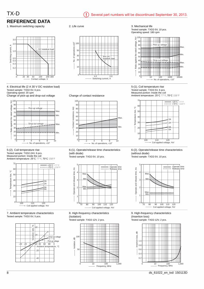
REFERENCE DATA1. Maximum switching capacity 2. Life curve 3. Mechanical life
Tested sample: TXD2-5V, 10 pcs.Operating speed: 180 cpm
0.2
0.3
0.40.5
1.0
2.0
3.0
20 30 50 100 200 3000Contact voltage, V
DC resistive load
Sw
itchi
ng c
urre
nt, A
1.0 2.0
100
50
30
20
10
0
30V DCresistive load
Switching current, A
No.
of o
pera
tions
x10
4
Max.
Min.
Min.
Max.
0
10
20
30
40
50
60
70
80
90
100
No. of operations, ×104
Rat
io a
gain
st th
e ra
ted
volta
ge, %
V
Pick-up voltage
Drop-out voltage
100001000100100
4. Electrical life (2 A 30 V DC resistive load)Tested sample: TXD2-5V, 6 pcs.Operating speed: 20 cpmChange of pick-up and drop-out voltage Change of contact resistance
5-(1). Coil temperature riseTested sample: TXD2-5V, 6 pcs.Measured portion: Inside the coilAmbient temperature: 25C 77F, 70C 158F
Max.
Min.
Max.
Min.
No. of operations, ×104
0
10
20
30
40
50
60
70
80
90
100
Rat
io a
gain
st th
e ra
ted
volta
ge, %
V
Pick-up voltage
Drop-out voltage
0 2 4 6 8 10No. of operations, ×104
0
10
20
30
40
50
60
70
80
90
100
Con
tact
res
ista
nce,
mΩ
0 2 4 6 8 10
Max.
Min.
100 110 120
2A
0A0A
Coil applied voltage, %V
Tem
pera
ture
ris
e, °
C
2A
+25°C+70°C
+77°F+158°F
70
60
50
40
30
20
10
0
5-(2). Coil temperature riseTested sample: TXD2-24V, 6 pcs.Measured portion: Inside the coilAmbient temperature: 25C 77F, 70C 158F
6-(1). Operate/release time characteristics (with diode)Tested sample: TXD2-5V, 10 pcs.
6-(2). Operate/release time characteristics (without diode)Tested sample: TXD2-5V, 10 pcs.
2A
0A0A
100 110 120Coil applied voltage, %V
Tem
pera
ture
ris
e, °
C
2A
+25°C+70°C
+77°F+158°F
70
60
50
40
30
20
10
0
1
2
4
5
70 80 100 1200
3
90 110
Max.
Max.Min.
Min.
Coil applied voltage, %V
Ope
rate
and
rel
ease
tim
e, m
s Release timeOperate time
1
2
4
5
70 80 100 1200
3
90 110
Max.
Max.Min.
Min.
Coil applied voltage, %V
Ope
rate
and
rel
ease
tim
e, m
s Release timeOperate time
7. Ambient temperature characteristicsTested sample: TXD2-5V, 5 pcs.
8. High-frequency characteristics (Isolation)Tested sample: TXD2-12V, 2 pcs.
9. High-frequency characteristics (Insertion loss)Tested sample: TXD2-12V, 2 pcs.
Var
iatio
n ra
tio, % 40
20
-20
-40
-40 200-20 40 60 80
Drop-out voltage
Pick-up voltage
Ambient temperature, °C
x
x
50
100 100 1,000
100
Frequency, MHz
Isol
atio
n, d
B
0.6
100 100 1,000
0.2
0.4
1.0
0.8
Frequency, MHz
Inse
rtio
n lo
ss, d
B

TX-DSeveral part numbers will be discontinued September 30, 2013.
9ds_61022_en_txd: 150113D
10. Malfunctional shock (single side stable)Tested sample: TXD2-5V, 6 pcs
11-(1). Influence of adjacent mountingTested sample: TXD2-12V, 6 pcs.
11-(2). Influence of adjacent mountingTested sample: TXD2-12V, 6 pcs.
Y'
Y
X Z
Z' X'
1000m/s 2
2
2
2
2
1000m/s 2
1000m/s
1000m/s
1000m/s
1000m/s
DeenergizedconditionEnergized conditionY
Y'
Z'Z X
X'
-5
0
5
-5
0
5 ON ON
ON
OFF OFF
OFF
1062 4 80
Inter-relay distance , mm inch
Rat
e of
cha
nge,
%R
ate
of c
hang
e, %
Pick-up voltage
Drop-out voltage
.394.236.079 .157 .315
-5
0
5
-5
0
5 ON
ON
ON
OFF
OFF
OFF
0 1062 4 8
Inter-relay distance , mm inch
Rat
e of
cha
nge,
%R
ate
of c
hang
e, %
Pick-up voltage
Drop-out voltage
.394.236.079 .157 .315
12. Actual load test (35 mA 48 V DC wire spring relay load)Tested sample: TXD2-5V, 6 pcs.
Circuit
Change of pick-up and drop-out voltage Change of contact resistance
48 V DC
458 Ω
0.08F
0.08F
458 Ω
43
TXD
+
–
Wire spring relay
0
10
20
30
40
50
60
70
80
90
100
No. of operation, ×104
Rat
io a
gain
st th
e ra
ted
volta
ge, %
V
Pick-up voltage
Drop-out voltage
0 10 20 30 40 50
Max.Min.
Max.
Min.
0
10
20
30
40
50
60
70
80
90
100
No. of operation, ×104
Con
tact
res
ista
nce,
mΩ
Min.Max.
50403020100
13-(1). Distribution of M.B.B. timeTested sample: TXD2-2M-5V, 50 pcs.Terminal No. 3-4-5: ON Terminal No. 3-4-5: OFF
100 150 200 250 300 350 400
150 200 250 300 350 400 450
μs min.
μs max.
~ ~ ~ ~ ~ ~ ~
x:σn-1:Min.:Max.:
300.5 μs55.3 μs165 μs415 μs
0
10
20
30
40
50
60
2
7
12
22
6
1
100 150 200 250 300 350 400
150 200 250 300 350 400 450
~ ~ ~ ~ ~ ~ ~
x:σn-1:Min.:Max.:
298.8 μs51.8 μs205 μs432 μs
μs min.
μs max.
0
10
20
30
40
50
60
12 1316
8
1
13-(2). Distribution of M.B.B. timeTested sample: TXD2-2M-5V, 50 pcs.Terminal No. 8-9-10: ON Terminal No. 8-9-10: OFF
14. Surge breakdown voltage testTested sample: TXD2-3V-6, 30 pcs.
100 150 200 250 300 350 400
150 200 250 300 350 400 450
~ ~ ~ ~ ~ ~ ~
x:σn-1:Min.:Max.:
293.4 μs60.4 μs155 μs445 μs
μs min.
μs max.
0
10
20
30
40
50
60
4
10 10
18
53
100 150 200 250 300 350 400
150 200 250 300 350 400 450
~ ~ ~ ~ ~ ~ ~
x:σn-1:Min.:Max.:
281.4 μs58.3 μs120 μs421 μs
μs min.
μs max.
60
50
40
30
20
10
01
46
1915
41
0
6
2
4
8
10
12
14
7000 7200 7400 7600 80007800 8200 8400 8600
Surge breakdown voltage, V

TX-D Several part numbers will be discontinued September 30, 2013.
10 ds_61022_en_txd: 150113D
DIMENSIONS (mm inch)
1. Surge breakdown voltage 2,500 V and 6,000 V types1) Standard PC board terminal
2) Surface-mount terminal
Schematic (Top view)
TypeExternal dimensions (General tolerance: 0.3 .012) Suggested mounting pad (Top view) (Tolerance: 0.1 .004)
Single side stable and 1 coil latching Single side stable and 1 coil latching
SA type
SS type
Download from our Web site.CAD DataCAD Data
CAD Data
CAD Data
External dimensionsStandard PC board terminal
15.00.591
7.40
0.25
1.15.020
5.08 2.54.045 .200 .100
5.08
.291
0.50
.010
.2003.50.138
8.20.323
.0260.65
PC board pattern (Bottom view)
Tolerance: 0.1 .004
5.08
2.54
8-1.0 dia.
10.16
.200
.100
8-.039 dia.
.400
Schematic (Bottom view)Single side stable
(Deenergized condition)
1 coil latching
(Reset condition)
Direction indication
12
1
8
5
9
4
10
3+
−
Direction indication
12
1
10
3
9
4
8
5−
+
2,500 V type
6,000 V type
CAD Data
.59115
0.65.026
5.08.200
5.08.200
2.54.100
8.2.323
0.5.020
0.25.010
8.4.331
9.4±0.5.370±.020
.2917.4
7.24.285
.1002.545.08
.2001.039
3.16.124
.59115
0.65.026 5.08
.200
5.08.200
0.25.010
0.5.020
8.2.323
2.54.100
Max.10.394
7.4±0.5.291±.020
.2917.4
.1002.545.08
.2001.039.085
2.16
6.24.246
Single side stable
(Deenergized condition)
1 coil latching
(Reset condition)
Direction indication
10
3
9
4
8
5
12
1
−
+
Direction indication
12
1
8
5
9
4
10
3
+
−

TX-DSeveral part numbers will be discontinued September 30, 2013.
11ds_61022_en_txd: 150113D
2. Surge breakdown voltage 6,000 V (High breakdown voltage type)1) Standard PC board terminal
2) Surface-mount terminal
Schematic (Top view)
TypeExternal dimensions (General tolerance: 0.3 .012) Suggested mounting pad (Top view) (Tolerance: 0.1 .004)
Single side stable and 1 coil latching Single side stable and 1 coil latching
SA type
SS type
CAD DataExternal dimensions
Standard PC board terminal
General tolerance: 0.3 .012
5.08
0.25
5.08 2.54
0.50.020
.0101.15
.200.200 .100.045
15.00.591
3.50.138
9.450.65.372.026
7.40.291
PC board pattern (Bottom view)
Tolerance: 0.1 .004
5.08
2.54
8-1.0 dia.
10.16
.200
.100
8-.039 dia.
.400
Schematic (Bottom view)Single side stable
(Deenergized condition)
1 coil latching
(Reset condition)
Direction indication
12
1
8
5
9
4
10
3+
−
Direction indication
12
1
10
3
9
4
8
5−
+
CAD Data
0.50.020
5.081.15 2.54.045 .100.200 9.40±0.5
.370±.020
5.08.200
15.00.591
9.45.372
0.65.026
7.40.291
9.65.380
0.25.010
7.24.285
.1002.545.08
.2001.039
3.16.124
Max. 11.25.443
7.40±0.5.291±.020
5.08.200
0.50.020 5.081.15 2.54
.045 .100.200
0.65.026
15.00.591
9.45.372
7.40.291
0.25.010
.1002.545.08
.2001.039.085
2.16
6.24.246
Single side stable
(Deenergized condition)
1 coil latching
(Reset condition)
Direction indication
10
3
9
4
8
5
12
1
−
+
Direction indication
12
1
8
5
9
4
10
3
+
−

TX-D Several part numbers will be discontinued September 30, 2013.
12 ds_61022_en_txd: 150113D
NOTES
For Cautions for Use, see Relay Technical Information.
1. Packing style1) Tube packingThe relay is packed in a tube with the relay orientation mark on the left side, as shown in the figure below.
2) Tape and reel packing (surface-mount terminal type)(1) Tape dimensions(i) SA type
mm inch
(ii) SS typemm inch
(2) Dimensions of plastic reelmm inch
3) Ambient temperature when transporting and during storage with the product in its original packaging: –40 to +70C –40 to +158F2. Automatic insertionTo maintain the internal function of the relay, the chucking pressure should not exceed the values below.
Chucking pressure in the direction A: 4.9 N {500gf} or lessChucking pressure in the direction B: 9.8 N {1 kgf} or lessChucking pressure in the direction C: 9.8 N {1 kgf} or lessPlease chuck the portion.Avoid chucking the center of the relay.In addition, excessive chucking pressure to the pinpoint of the relay should be avoided.3. M.B.B. typeA small OFF time may be generated by the contact bounce during contact switching. Check the actual circuit carefully.If the relay is dropped accidentally, check the appearance and characteristics including M.B.B. time before use.
Orientation (indicates PIN No.1) stripe
Stopper (gray) Stopper (green)
TX-D relays
Tape coming out direction
16.0.630
.394
4.0
24.0 ±0.3
.945 ±.012 ±0.29.2±.008.362
0.4
C
BA
D
Relay polarity bar(Z type) 2.0
11.5
1.75
15.5
.059 dia.+.004 0
1.5 dia.+0.1 0
.157 .016.079 .069
.610.453
10.0
8.0.315
16.0TX-D relays
Tape coming out direction
.630
4.0
24.0 ±0.3
.945 ±.012±0.210.8±.008.425
0.4Relay polarity bar(Z type)
2.0
11.5
15.5
1.75.059 dia.+.004 0
1.5 dia.+0.1 0
.157 .016.079 .069
.453
.610
±.024.827±0.621
dia.dia.
±.020.512±0.513
dia.dia.
±0.22.0±.008.079
+2 024.4
+.079 0.961
.079±.0202.0±0.5
±180
380
dia.
dia.±2
±.0393.150
14.961
dia.
dia.±.079
AC B
5V DC
Min. 10μs
500Ω
Measuring condition of M.B.B. time