
Testing Time Domain Passivity Control of Haptic …...freedom, the PO and PC were implemented in a 2...
16
Testing Time Domain Passivity Control of Haptic Enabled Systems Blake Hannaford Jee-Hwan Ryu Dong-Soo Kwon a Yoon Sang Kim Jae-Bok Song b a Dept. of Mechanical Engineering, KAIST, Taejon, South Korea b Dept. of Mechanical Engineering, Korea University, Seoul, South Korea Electrical Electrical Engineering Engineering UW UW UWEE Technical Report Number UWEETR-2002-0010 June 2002 Department of Electrical Engineering University of Washington Box 352500 Seattle, Washington 98195-2500 PHN: (206) 543-2150 FAX: (206) 543-3842 URL: http://www.ee.washington.edu
Transcript of Testing Time Domain Passivity Control of Haptic …...freedom, the PO and PC were implemented in a 2...

Testing Time Domain Passivity Control of Haptic EnabledSystems
Blake Hannaford Jee-Hwan Ryu Dong-Soo Kwona Yoon Sang KimJae-Bok Songb
aDept. of Mechanical Engineering, KAIST, Taejon, South KoreabDept. of Mechanical Engineering, Korea University, Seoul, South Korea
ElectricalElectricalEngineeringEngineering
UWUW
UWEE Technical ReportNumber UWEETR-2002-0010June 2002
Department of Electrical EngineeringUniversity of WashingtonBox 352500Seattle, Washington 98195-2500PHN: (206) 543-2150FAX: (206) 543-3842URL: http://www.ee.washington.edu

Testing Time Domain Passivity Control of Haptic EnabledSystems
Blake Hannaford Jee-Hwan Ryu Dong-Soo Kwon Yoon Sang KimJae-Bok Song
University of Washington, Dept. of EE, UWEETR-2002-0010
June 2002
Abstract
Much recent work has studied the means of achieving stable yet high performance control of haptic interfaces.Such interfaces provide compelling force feedback in virtual reality simulations for medical training, advanced com-puter aided design (CAD), entertainment, and other applications. This paper reports experimental testing of a newmethod of stable haptic interface control, the Passivity Observer (PO) and Passivity Controller (PC). Experimentalresults from three different laboratories confirm basic operation of the PO/PC. The PO/PC method is applied to highstiffness haptic interaction, to a 2-degree-of-freedom (DOF) system with coupled kinematics and dynamics, and toa bi-lateral telemanipulation system controlling metal-to-metal contact. (An abridged version of this report will bepublished in Proceedings of the International Symposium on Experimental Robotics 2002 (ISER-02), ExperimentalRobotics 2002, B. Siciliano and P. Dario eds. Series in Advanced Robotics, Springer Verlag.)
1 Introduction
One of the most important issues in haptic interface design is to achieve stable interaction between the haptic displayand the virtual environment for any operating conditions and for any virtual environment parameters. Vibration ordivergent behavior caused by the instabilities is very distracting, can damage the hardware, and in large systems, mayeven pose a physical threat to the human operator. The facts that virtual environments of interest are always non-linearand dynamic properties of a human operator are always involved, can make it especially difficult to analyze hapticsystems in terms of known parameters and linear control theories. Colgate et. al. [1] and Zilles and Salisbury [2]introduced the “virtual coupling” between haptic display and virtual environment, which is a practical way to increasethe stability of a haptic interface independent of human grasp impedance and of the details of virtual environmentdesign. One fruitful avenue to ensure stable operation is to use the idea of passivity[3, 4, 5, 6, 7, 8, 9].
Recently, Hannaford and Ryu [10, 11, 16] proposed an energy based method, whose components are termed the“Passivity Observer” (PO) and “Passivity Controller” (PC). The PO measures the total amount of energy dissipatedin the haptic interface system and identifies time samples in which this energy becomes negative (indicating activebehavior). The PC adds a calculated amount of damping to constrain PO ≥ 0. This paper explores some implemen-tation issues in the PO/PC method. In particular, we will explain and experimentally test features added to the methodto: 1) take care of the case where excessive build-up of energy in the PO might prevent or delay the PC from promptlyoperating to stabilize the system, 2) explore the applicability to a planar robot with coupled degrees of freedom, and3) test the method in a master-slave teleoperation system with bi-lateral kinesthetic coupling.
2 Time Domain Passivity Control
In this section we review our passivity observer and controller. For more details, and the stability proof, see [10, 11].Force and velocity are the key variables which define the nature of haptic contact. First, we define the sign conventionfor all forces and velocities so that their product is positive when power enters the system port (Fig. 1). We alsoassume that the system has initial stored energy at t = 0 of E(0). We then use the following widely known definitionof passivity.
1
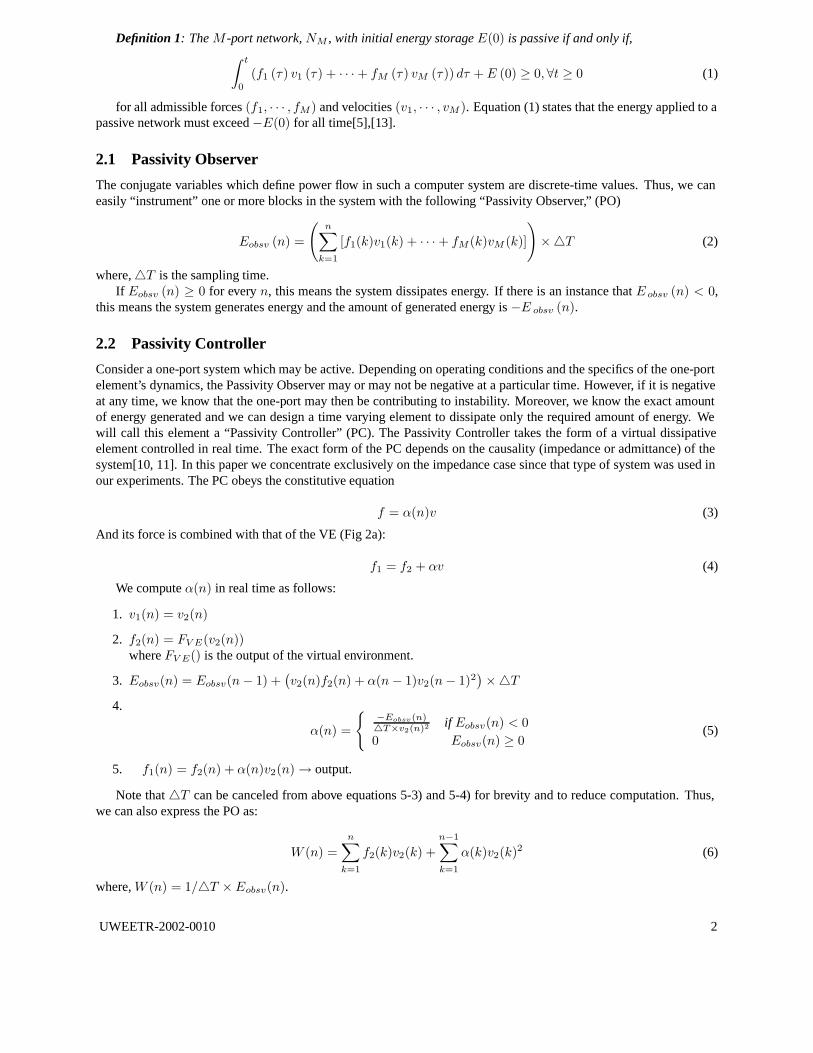
Definition 1: The M -port network, NM , with initial energy storage E(0) is passive if and only if,∫ t
0
(f1 (τ) v1 (τ) + · · · + fM (τ) vM (τ)) dτ + E (0) ≥ 0, ∀t ≥ 0 (1)
for all admissible forces (f1, · · · , fM ) and velocities (v1, · · · , vM ). Equation (1) states that the energy applied to apassive network must exceed −E(0) for all time[5],[13].
2.1 Passivity Observer
The conjugate variables which define power flow in such a computer system are discrete-time values. Thus, we caneasily “instrument” one or more blocks in the system with the following “Passivity Observer,” (PO)
Eobsv (n) =
(
n∑
k=1
[f1(k)v1(k) + · · · + fM (k)vM (k)]
)
×4T (2)
where, 4T is the sampling time.If Eobsv (n) ≥ 0 for every n, this means the system dissipates energy. If there is an instance that E obsv (n) < 0,
this means the system generates energy and the amount of generated energy is −E obsv (n).
2.2 Passivity Controller
Consider a one-port system which may be active. Depending on operating conditions and the specifics of the one-portelement’s dynamics, the Passivity Observer may or may not be negative at a particular time. However, if it is negativeat any time, we know that the one-port may then be contributing to instability. Moreover, we know the exact amountof energy generated and we can design a time varying element to dissipate only the required amount of energy. Wewill call this element a “Passivity Controller” (PC). The Passivity Controller takes the form of a virtual dissipativeelement controlled in real time. The exact form of the PC depends on the causality (impedance or admittance) of thesystem[10, 11]. In this paper we concentrate exclusively on the impedance case since that type of system was used inour experiments. The PC obeys the constitutive equation
f = α(n)v (3)
And its force is combined with that of the VE (Fig 2a):
f1 = f2 + αv (4)
We compute α(n) in real time as follows:
1. v1(n) = v2(n)
2. f2(n) = FV E(v2(n))where FV E() is the output of the virtual environment.
3. Eobsv(n) = Eobsv(n − 1) +(
v2(n)f2(n) + α(n − 1)v2(n − 1)2)
×4T
4.
α(n) =
{
−Eobsv(n)4T×v2(n)2 if Eobsv(n) < 0
0 Eobsv(n) ≥ 0(5)
5. f1(n) = f2(n) + α(n)v2(n) → output.
Note that 4T can be canceled from above equations 5-3) and 5-4) for brevity and to reduce computation. Thus,we can also express the PO as:
W (n) =
n∑
k=1
f2(k)v2(k) +
n−1∑
k=1
α(k)v2(k)2 (6)
where, W (n) = 1/4T × Eobsv(n).
UWEETR-2002-0010 2

3 Basic PO/PC operation
The PO/PC was tested experimentally on our “Excalibur,” 3-axis, high force output, haptic interface system in thelaboratory [12, 10] (Fig 3(a)). This system consists of the following elements (Fig 4) : human operator (HO), HapticInterface (HI), haptic controller (HC) having feed forward gravity compensation and friction compensation, the passiv-ity controller (PC), and the virtual environment (VE). The system is entirely synchronous at 1000Hz. The HI sensesposition in 0.008mm increments, and can display 200N force inside a 300x300x200mm workspace. The virtualenvironment consists of virtual LEGOTM blocks (Fig 3(b)). In the experiments, the PO accounted for energy flow inthe HC, PC, and VE. The virtual object parameter had very high stiffness (k = 90kN/m). The operator approachedthe object at about 200mm/s.
3.1 Unstable operation and behavior of PO
In the first experiment, without the PC, the contact was unstable, resulting in an oscillation observable as force pulses(Fig 6b) ; the passivity observer (Fig 6c) was initially positive, but grew to more and more negative values with eachcontact. Note that the initial two bounces were passive, but after the third bounce the system gets active.
3.2 Stabilization of contact via PC
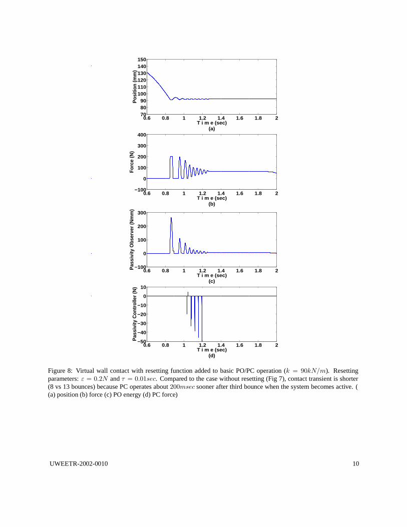
In the second experiment, with the PC turned on, the operator approached the virtual object at the same velocity(Figure 7a), but a stable contact was achieved with about 13 bounces (Fig 7b). Again the first bounce can be seen tobehave passively, but the subsequent bounces were active (Figure 7c). After eight bounces, the PC began to operate(Figure 7d), and eliminated the oscillation.
4 Implementation Issues
4.1 “Resetting”
A virtual environment typically contains different properties in different regions of space. One issue which can besignificant for the PO/PC is that one portion of the VE may be passive while another is active. If the user interacts fora long time with the passive portion, the PO acquires a “build-up” of dissipated energy. If the user now moves andinteracts with the active region, the PC will not work until total active behavior equals the accumulated energy valuein the PO. A second case occurs locally, when non-linear behavior of the environment can cause dissipative behaviorclosely followed by active behavior (Figures 6 & 7). In both cases, if the energy accumulated in the PO can be reset tozero properly, then faster stable contact can be achieved with smaller bounces. With this motivation, we want to derivea heuristic rule, called “resetting” throughout this paper, and based on the detection of free motion state.
The rule is as follows. If |f | < ε for τ sec, then Reset the PO to zero. where we call ε the force threshold, and τ theduration. The idea is that this rule can detect free motion and that problems of active behavior do not persist from onecontact state to the next. Thus it might be appropriate to reset the PO in between contacts with virtual surfaces. Weexperimented with the force threshold ε and duration τ to get values for correct detection of the free motion regime.A wide variety of values were studied and explored in the experiment. We expressed the force threshold as a fractionof the maximum force output of the device and the duration as multiples of the sampling time, T = 0.001sec. In freemotion, f is exactly zero without any noise because it is computed by the virtual environment.
4.2 Coupled Degrees of Freedom
Most of the initial development of the PO/PC has taken place in a single degree of freedom, or on devices withdecoupled degrees of freedom. Theoretically there should be no difference in passivity of a system introduced by thetransformation of force and velocity between Cartesian Space and joint space. Note that the textbook derivation of theJacobian matrix using the principle of virtual work assumes that the incremental kinematics are passive.
To verify the ability of the PO/PC method to work with non-linear kinematics and coupling between degrees offreedom, the PO and PC were implemented in a 2 DOF version of a 5 DOF haptic arm master developed at KoreaUniversity (Fig. 9). To create this experimental system, 3 of the 5 DOF were immobilized. The controller samplingperiod was set to 1msec, and the resolution of angular displacement and velocity at the joints were 0.0024 radians and
UWEETR-2002-0010 3

HH
HH
Hτ
ε10
−7× FMAX 10
−3× FMAX 10
−1× FMAX
1× T viscous feeling in free motion . . . too much resetting
10 × T . . . good performance . . .100× T viscous feeling in free motion . . . no resetting
Table 1: Results of varying the parameters, ε (the force threshold) and τ (the duration) of the Passivity Observerresetting rule (T = 1msec, FMAX = 200N).
0.00027 rad/sec, respectively A virtual wall of 45 kN/m stiffness was placed parallel to and 300mm below the X-axisas shown in Fig 9(b). The manipulator was released from the initial position and came into contact with the virtualwall. Without the PO and PC, the responses showed oscillatory (and unstable) behavior, and the endpoint bouncedabout 10mm above the virtual wall after the first contact. Experiments with the PO/PC were performed in both jointspace and Cartesian space. The relationship between the endpoint velocity V = [V x Vy ]T and the joint velocityθ = [θ1 θ2]
T is described by J(θ), where J is the Jacobian matrix.
4.3 Bi-lateral System
Figure 5 shows a network model of a teleoperation system which can be represented as a two-port network terminatedby two one-ports, the human operator and the environment. v m and vs denote the velocity of the master and slavemanipulator, respectively. fh represents the force that the operator applies to the master manipulator, and f e denotesthe force that the slave manipulator applies to the environment. Details of the two-port PO/PC implementation canbe found in [16]. The PO computation is easily derived from 2. Although the PC may be placed at either port, it isadvantageous to put one at each of the two ports[16]. When the two-port is active, (i.e. equation 2 < 0) three casesmust be considered:
1. Energy flows out the human operator (master) port.
2. Energy flows out the slave port.
3. Energy flows out both ports.
Our method places the dissipation at the port where energy is produced during active behavior and allocates thedissipation energy between the two ports for case three.
5 Experimental results
5.1 Resetting
We added resetting to the experimental system as described in section 4.1. The results obtained (Table 1) are summa-rized as follows:
• When 10−7 ×FMAX was chosen for the force threshold and τ was 1×T or 100×T , we found a very sluggishfeeling in free motion : the resetting was continuous and the PC was operating all the time.
• When a big value (10−1 × FMAX ) was chosen as the force threshold with τ = 100× T , we found no resettingeven during the contact. The PC could not operate and instability was not prevented until the PO was dissipated.
• When the duration equals the sampling time (1 × Tsec ), there was too much resetting. In the case of ε =10−1 × FMAX with such a short duration, resetting was done when even a single noisy signal is less than theforce threshold, and the PC operates too much. Faster stable contact was not achieved.
• Finally, we determined ε = 0.2N, (10−3 × FMAX) and τ = 0.01sec, (10× T ) were best values.
With the PC and resetting turned on (ε = 0.2N and τ = 0.01sec), a stable contact was achieved with about 8bounces (Fig 8b). Compared to 13 bounces with no resetting (Fig 7), the contact transient was shorter because the PCoperated about 200msec sooner after the initial contact. Resetting helped the PC to operate immediately as soon asthe system becomes active without changing the stability, just as proposed.
UWEETR-2002-0010 4

5.2 Coupled Degrees of Freedom
We now consider experimentation at Korea University on the 2-DOF system with coupled kinematics and dynamicsdescribed in section 4.2. Basic operation of the PO/PC was assessed with virtual wall contact experiments in whichthe manipulator was allowed to fall under the influence of earth gravity until it made virtual contact. Note that thehuman operator released the device and was not in contact during the experiment — an extreme case for instability.
With the PC operating in Cartesian space, the phase plane response of the system rapidly reached the equilibriumpoint representing stable contact (Y = -300mm, 0m/s, Figure 10). Without the PC, the otherwise identical systemencountered limit cycles (not shown here) around the equilibrium point. The response in the Y direction settled in thefinal position with only a little oscillation (i.e., a maximum bounce of 2mm), and the passivity level was maintainedpositive except for the instant just after the first contact. Only the response in the Y direction is shown in the figure,but the X-direction response showed a similar trend.
Figure 11 illustrates the 2-DOF system with the PO/PC activated in joint space. As in the case of the Cartesianspace scheme, the responses of both joints provide satisfactory behavior in terms of stability. In the joint space scheme,the PO and PC were implemented for both joints separately in such a way that the PCs maintain positive passivity levelsat both joints.
5.3 Bi-lateral System
In this section we describe experiments conducted at the Korean Advanced Institute of Science and Technology(KAIST), Taejon Korea, on the teleoperation system with force-feedback described in section 4.3. In these experi-ments, the PO and PC were added to a teleoperation system consisting of a two-DOF master and slave manipulator(Figure 12). A steel wall was placed parallel to the Y-Axis. A position/force control architecture was used for thebilateral controller. The control system was entirely synchronous at 1000 Hz. Each axis of the master and slave sensedposition in increments of 1.7× 10⁻⁴ rad. Resetting was not used.
In the first experiment, without the PC, the operator maneuvered the master to make the slave contact the hard wallat about 23.3 mm/s. Since the operator made contact at relatively low velocity and gradually increased the interactionforce after contact (Figure 13), stable contact was achieved even though the wall was very stiff (at least 150 kN/m).Only X-direction signals are plotted since the main interaction occurs on the X-Axis. Note that the energy in Fig. 13c(and the following figures) means net supplied energy to the bilateral controller and the PC, and this energy equals thesum of the value of the PO and the dissipation amount of the PC,
Eobsv(n) + α1(n)vm(n)2 + α2(n)vs(n)2
When the operator maneuvered the master to contact at higher velocity of about 120 mm/s, contact was unstable.This resulted in an oscillation observable as force and position pulses (Figure 14); the value of the PO was initiallypositive, but became increasingly negative with each contact. As in our haptic interface experiments (Figures 6 & 7),the initial bounce was passive, but from the second bounce the system became active. In the next experiment, withthe PC turned on, the operator approached the contact point at the same velocity (Figure 15), but stable contact wasachieved with about 7 bounces. Again the first bounce behaved passively, but subsequent smaller bounces were active(Figure 15c). On the second bounce, the PC at the master port began to operate and eliminated the oscillation bybriefly modifying the transmitted force to the operator. On the other hand, the PC at the slave port only operated onthe second bounce.
Finally, we studied the behavior of the bi-lateral system during a low velocity experiment, in which the operatormaneuvered the master to make the slave contact a diagonal hard wall at about 30 mm/s, and made sliding contact.Without the PC (not shown) the contact became unstable after t = 1.5 sec, resulting in an increasing oscillation ob-servable as position and force pulses. The PO became increasingly negative with each contact. With the PC turned on,the operator maneuvered the teleoperator in the same way, but stable surface following was achieved (Figure 16). Thesmall force bounces before t = 1.2 sec behaved passively, but the following small force bounces were active. Aftert = 1.7 sec, the PC at the master and slave port began to operate, and eliminated the oscillation by modifying thetransmitted force to the operator. However, the PC output consisted of a noise-like signal during the surface following(after t = 1.7 sec). The noisy behavior of the PC coincides with a period of low velocity.
UWEETR-2002-0010 5

6 Conclusion
In this report, some practical issues relating to the performance of the PO/PC method were experimentally studied.First, a heuristic rule to reset stored energy in the PO based on the detection of a free motion state is derived, andexperiments verified that this resetting helps the PC to operate quickly when the system gets active without changingthe stability. Further experimentation demonstrated effects of parameters outside their optimum ranges. The heuristicresetting rule adds built-in assumptions to the stabilizing Passivity Controller. This heuristic rule may not be suitablefor all virtual environments. Extensive experimental testing will be required to fully verify the method for a givenapplication.
The system was also applied to a 2-DOF planar mechanism with coupled kinematics and dynamics. The PO/PCsuccessfully stabilized contact with a virtual wall in both Cartesian and joint spaces. By generalizing the method totwo energy ports, the PO/PC was applied to a bi-lateral teleoperation system, and successfully stabilized controlledstatic and sliding contact with a hard surface. The PO/PC system is a promising method to address many stabilityissues associated with force feedback systems. Experimental evaluation on a wide variety of hardware systems isgiving us a better idea of its strengths and limitations.
Acknowledgments
We are pleased to acknowledge research support from Ford Motor Company. Postdoctoral and Visiting Scholar supportfrom the Government of Korea, and fruitful collaborations with KAIST and Korea University.
References
[1] J. E. Colgate, M. C. Stanley, J. M. Brown, “Issues in the Haptic Display of Tool Use,” Proc. IEEE/RSJ Int. Conf.on Intelligent Robotics and Systems, Pittsburgh, PA, 1995, pp. 140-145.
[2] C. B. Zilles and J. K. Salisbury, “A Constraint-based God-object Method for Haptic Display,” Proc. IEEE/RSJInt. Conf. on Intelligent Robotics and Systems, Pittsburgh, PA, 1995, pp. 146-151.
[3] N. Hogan, “Controlling Impedance at the Man/Machine,” Proc. IEEE Int. Conf. Robot. Automat., Scottsdale,AZ, 1989, pp. 1626-1631.
[4] R. J. Adams, D. Klowden, B. Hannaford, “Stable Haptic Interaction using the Excalibur Force Display,” Proc.IEEE Int. Conf. Robot. Automat., San Francisco, CA, 2000, pp. 770-775.
[5] R. J. Adams and B. Hannaford, “Stable Haptic Interaction with Virtual Environments,” IEEE Trans. Robot.Automat., vol. 15, no. 3, 1999, pp. 465-474.
[6] K. Hashtrudi-Zaad and S.E. Salcudean, “Analysis and evaluation of stability and performance robustness forteleoperation control architectures,” Proc. IEEE Int. Conf. Robot. Automat., San Francisco, CA, 2000, pp. 3107- 3113.
[7] S.E. Salcudean, K. Hashtrudi-Zaad, S. Tafazoli, S.P. DiMaio, and C. Reboulet, “Bilateral matched-impedanceteleoperation with application to excavation control,” IEEE Cont. Sys. Mag., vol. 19 no. 5, 1999, pp. 29 - 37.
[8] B. E. Miller, J. E. Colgate and R. A. Freeman, “Computational Delay and Free Mode Environment Design forHaptic Display,” Proc. ASME Dyn. Syst. Cont. Div., 1999b, pp. 229 - 236.
[9] B. E. Miller, J. E. Colgate and R. A. Freeman, “Environment Delay in Haptic Systems,” Proc. IEEE Int. Conf.Robot. Automat., San Francisco, CA, April, 2000, pp. 2434-2439.
[10] B. Hannaford, J. H. Ryu, “Time Domain Passivity Control of Haptic Interfaces,” Proc. IEEE Int. Conf. Robot.Automat., Seoul, Korea, 2001, pp. 1863-1869.
[11] B. Hannaford, J. H. Ryu, “Time Domain Passivity Control of Haptic Interfaces,” IEEE Transactions on Roboticsand Automation, vol. 18, pp. 1-10, February, 2002.
UWEETR-2002-0010 6

(a) (b)
Figure 1: One-port (a) and M-port networks (b)
(a)
Figure 2: Configuration of Passivity Controller for one-port networks with impedance causality.
[12] R. J. Adams, M. R. Moreyra, B. Hannaford, “Excalibur, A Three-Axis Force Display,” ASME Winter AnnualMeeting Haptics Symposium, Nashville, TN, November, 1999.
[13] C. A. Desoer and M. Vidyasagar, Feedback Systems: Input-Output Properties, New York: Academic Press, 1975.
[14] Claasen, T., W. F. G. Mecklenbrauker and J. B. H. Peek, “Frequency Domain Criteria for the Absence of Zero-Input Limit Cycles in Nonlinear Discrete-Time Systems, with Applications to Digital Filters,” IEEE Trans. Cir-cuits and Systems, vol. CAS-22, no. 3, 1975, pp. 232 - 239.
[15] I. Amidror, S. Usui, “Digital-Low Pass Differentiation for Biological Signal Processing,” IEEE Trans. Biomedi-cal Engineering, vol. 29, 1982, pp. 686-692.
[16] J.H. Ryu, D.S. Kwon, B. Hannaford, “Stable Teleoperation with Time Domain Passivity Control,” Proc. IEEEInt. Conf. Robotics and Automation, Arlington, VA, May 2002.
UWEETR-2002-0010 7

(a) (b)
Figure 3: “Excalibur”, high force output haptic device (a) and virtual LEGO (TM) blocks (b)
Figure 4: Network diagram of haptic interface system as implemented in the “Excalibur” 3-axis, high force output,device. System consists of human operator (HO), Haptic Interface (HI), haptic controller (HC) with feed forwardgravity compensation and friction compensation, passivity controller (PC), and the virtual environment (VE).
Figure 5: Network representation of bi-lateral teleoperator as two-port network. (00030.eps)
UWEETR-2002-0010 8

0.6 0.8 1 1.2 1.4 1.6 1.8 2708090
100110120130140150
Pos
ition
(mm
)
T i m e (sec) (a)
0.6 0.8 1 1.2 1.4 1.6 1.8 2−100
0
100
200
300
400
For
ce (N
)
T i m e (sec) (b)
0.6 0.8 1 1.2 1.4 1.6 1.8 2−100
0
100
200
300
Pas
sivi
ty O
bser
ver (
Nm
m)
T i m e (sec) (c)
0.6 0.8 1 1.2 1.4 1.6 1.8 2−50
−40
−30
−20
−10
0
10
Pas
sivi
ty C
ontro
ller (
N)
T i m e (sec) (d)
Figure 6: Unstable contact with high stiffness (k =90kN/m) virtual wall without Passivity Controller (PC).During oscillation, the Passivity Observer (PO) growsmore negative with each contact. ( (a) position (b) force(c) PO energy (d) PC force )
0.6 0.8 1 1.2 1.4 1.6 1.8 2708090
100110120130140150
Pos
ition
(mm
)
T i m e (sec) (a)
0.6 0.8 1 1.2 1.4 1.6 1.8 2−100
0
100
200
300
400
For
ce (N
)
T i m e (sec) (b)
0.6 0.8 1 1.2 1.4 1.6 1.8 2−100
0
100
200
300 P
assi
vity
Obs
erve
r (N
mm
)
T i m e (sec) (c)
0.6 0.8 1 1.2 1.4 1.6 1.8 2−50
−40
−30
−20
−10
0
10
Pas
sivi
ty C
ontro
ller (
N)
T i m e (sec) (d)
Figure 7: Virtual wall under same conditions as Figure 6but with the PC turned on. The PC began to operate andeliminated the oscillation after eight bounces when all theenergy accumulated in the PO was dissipated. Note that itwas after the third bounce when the system became active.((a) position (b) force (c) PO energy (d) PC force )
UWEETR-2002-0010 9
0.6 0.8 1 1.2 1.4 1.6 1.8 2708090
100110120130140150
Pos
ition
(mm
)
T i m e (sec) (a)
0.6 0.8 1 1.2 1.4 1.6 1.8 2−100
0
100
200
300
400 F
orce
(N)
T i m e (sec) (b)
0.6 0.8 1 1.2 1.4 1.6 1.8 2−100
0
100
200
300
Pas
sivi
ty O
bser
ver (
Nm
m)
T i m e (sec) (c)
0.6 0.8 1 1.2 1.4 1.6 1.8 2−50
−40
−30
−20
−10
0
10
Pas
sivi
ty C
ontro
ller (
N)
T i m e (sec) (d)
Figure 8: Virtual wall contact with resetting function added to basic PO/PC operation (k = 90kN/m). Resettingparameters: ε = 0.2N and τ = 0.01sec. Compared to the case without resetting (Fig 7), contact transient is shorter(8 vs 13 bounces) because PC operates about 200msec sooner after third bounce when the system becomes active. ((a) position (b) force (c) PO energy (d) PC force)
UWEETR-2002-0010 10

Figure 9: PO/PC control was evaluated with a 2-DOF version of the Haptic arm master manipulator developed atKorea University. The device was interfaced to a virtual wall of stiffness 45 kN/m
Figure 10: Contact with stiff virtual wall with PO/PC activated in Cartesian space (2 DOF experiment) (a) Phaseportrait (b) Responses of Y axis
Figure 11: 2-DOF PO/PCcontrol evaluated in jointspace. (a) Responses of joint1. (b) Responses of joint 2.
UWEETR-2002-0010 11

Figure 12: Experimental two DOF bi-lateral teleoperation system.
UWEETR-2002-0010 12

Figure 13: Hard contact made with the 2-DOF teleoperation system at low velocity was stable, even without thePO/PC.
UWEETR-2002-0010 13

Figure 14: At higher velocity (relative to Figure 13) tele-operated contact was highly unstable.
Figure 15: High velocity contact with the PO/PC enabledwas stablized within about 3 bounces. Remaining tran-sient contact forces are typical of stable metal-to-metalcontact.
UWEETR-2002-0010 14

Figure 16: PO/PC enabled stable contact with slantedwall. Some PO/PC noise was observed (t= 1.8 – 3.0 sec-onds).
UWEETR-2002-0010 15


