Testing Results of the Electronically Switched HF BPF ... BPF Testing Rev 1.pdf · Testing Results...
19
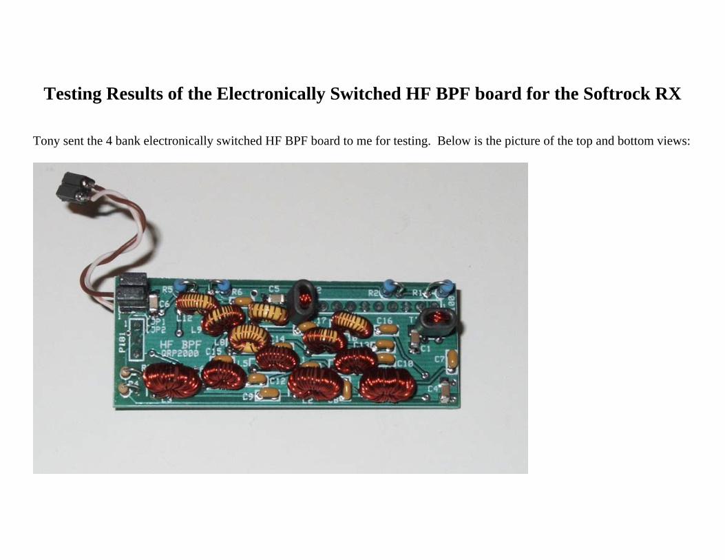
Testing Results of the Electronically Switched HF BPF board for the Softrock RX Tony sent the 4 bank electronically switched HF BPF board to me for testing. Below is the picture of the top and bottom views:
-
Upload
truongthuy -
Category
Documents
-
view
229 -
download
0
Transcript of Testing Results of the Electronically Switched HF BPF ... BPF Testing Rev 1.pdf · Testing Results...
Testing Results of the Electronically Switched HF BPF board for the Softrock RX
Tony sent the 4 bank electronically switched HF BPF board to me for testing. Below is the picture of the top and bottom views:

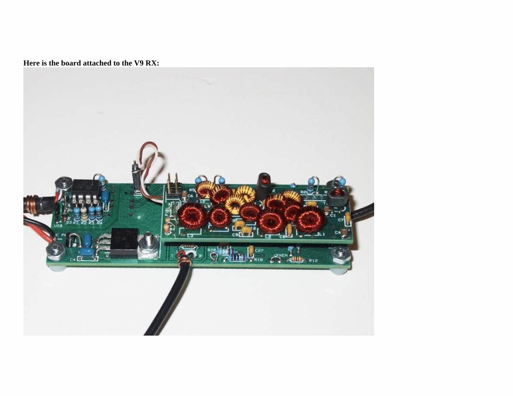
Here is the board attached to the V9 RX:
Test cables were made to connect 5V to the board and RF in and out measurement using a N2PK Vector Network Analyzer. The VNA RF output is connected to pins 1 and 2 of the 9 pin header. Output measurements were made across the entire secondary output (to match 50 ohm impedance) on pins 8 and 9 of the 9 pin header. Some differences were noted depending on which secondary pin is used as the ground connection to the VNA.
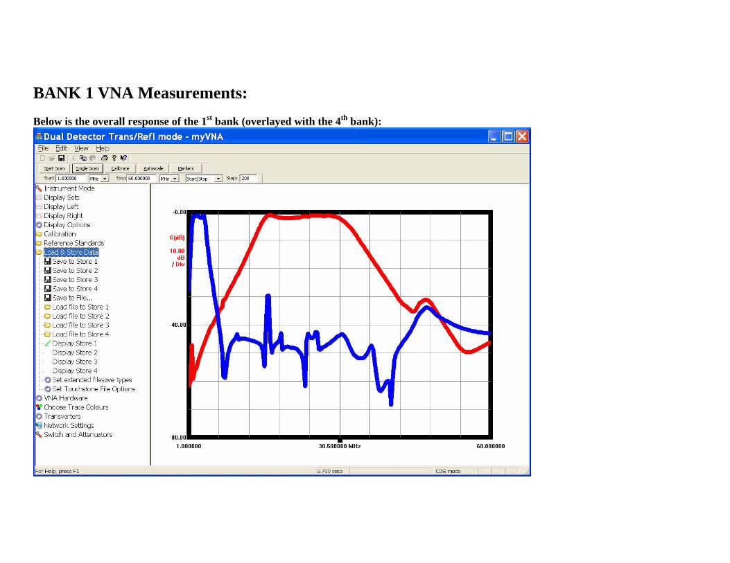
BANK 1 VNA Measurements: Below is the overall response of the 1st bank (overlayed with the 4th bank):
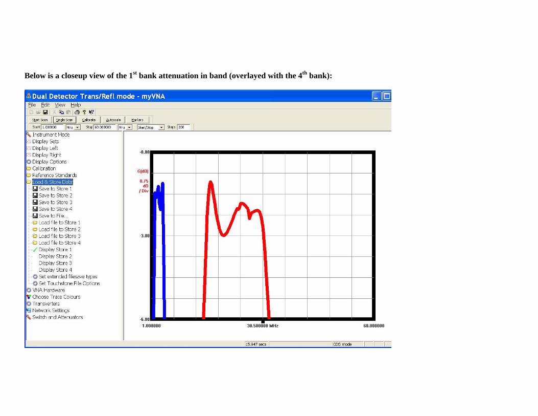
Below is a closeup view of the 1st bank attenuation in band (overlayed with the 4th bank):
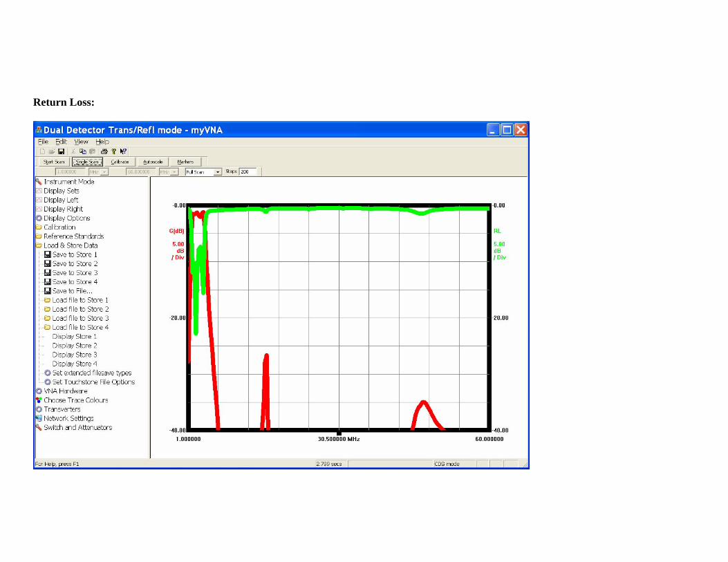
Return Loss:
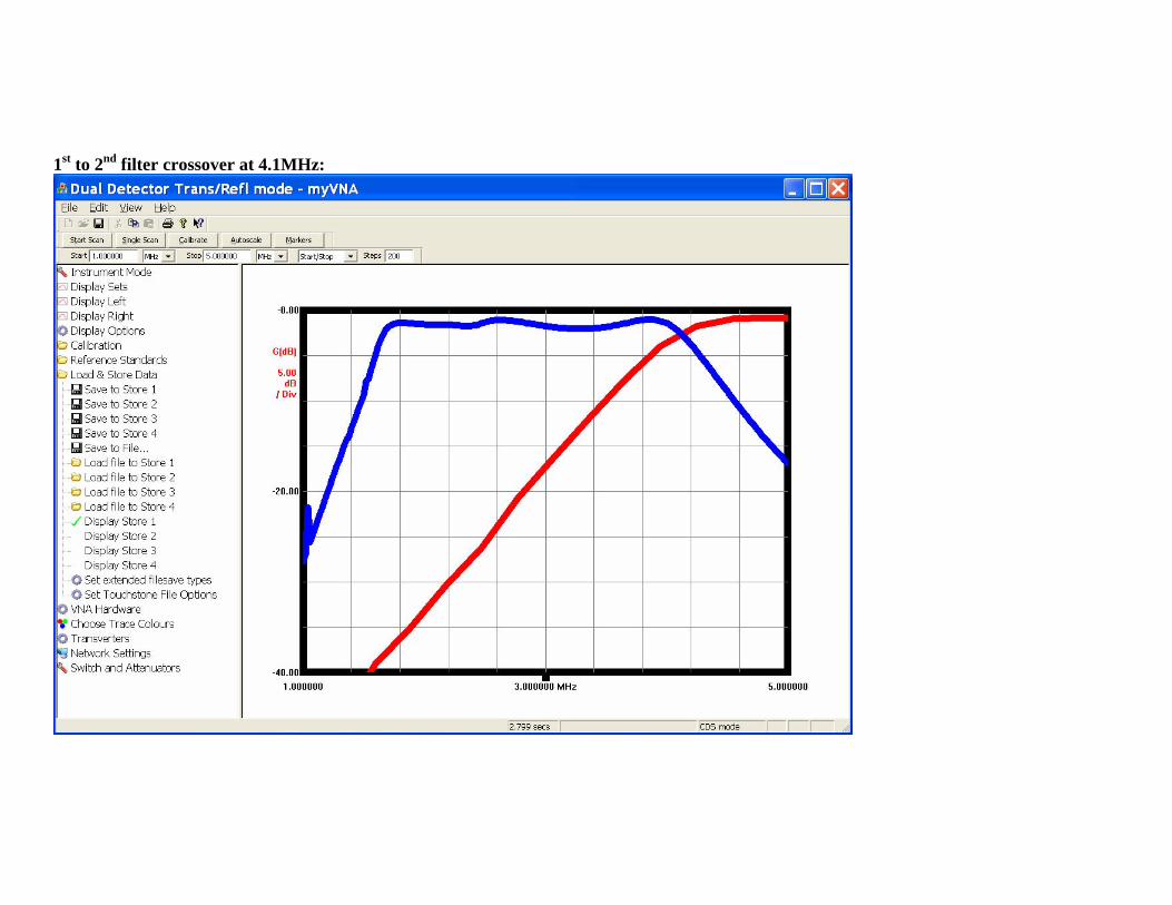
1st to 2nd filter crossover at 4.1MHz:

1. BANK 2 VNA Measurements: Below is the overall response of the 2nd bank (overlayed with the 4th bank):

Below is a closeup view of the 2nd bank attenuation in band (overlayed with the 4th bank):
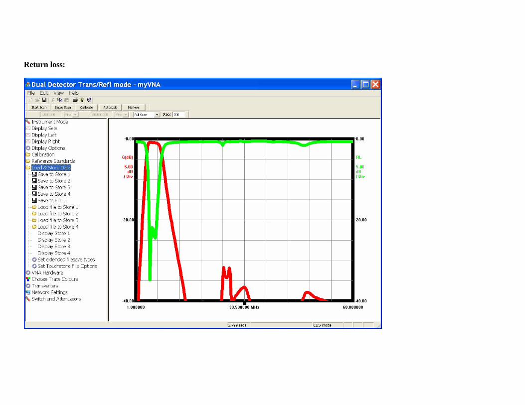
Return loss:
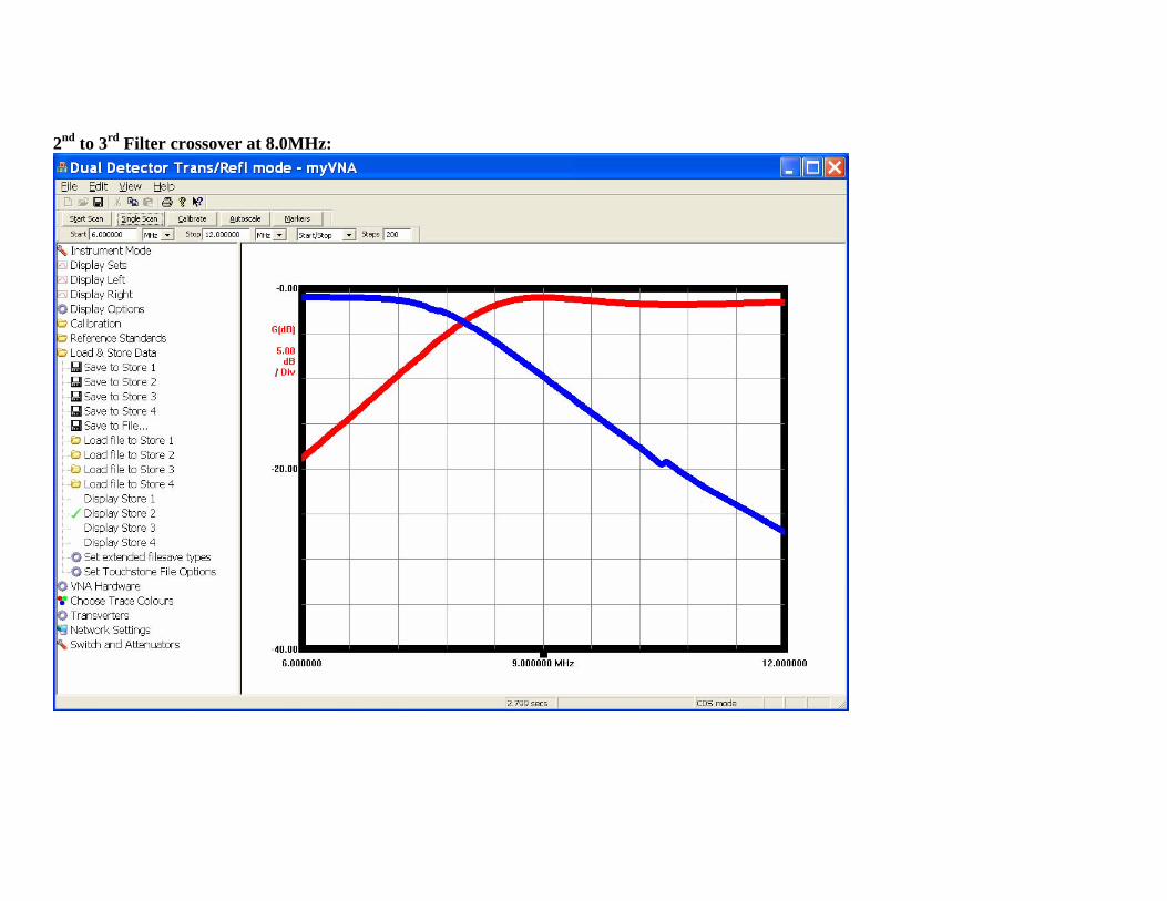
2nd to 3rd Filter crossover at 8.0MHz:
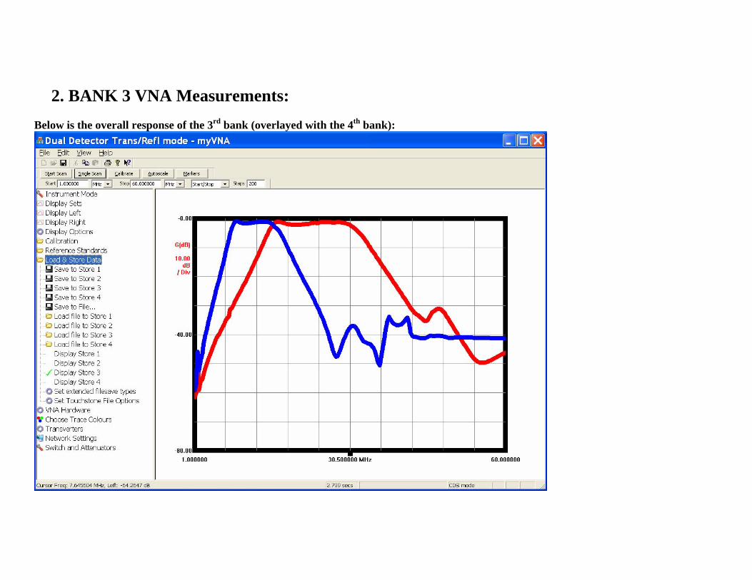
2. BANK 3 VNA Measurements: Below is the overall response of the 3rd bank (overlayed with the 4th bank):
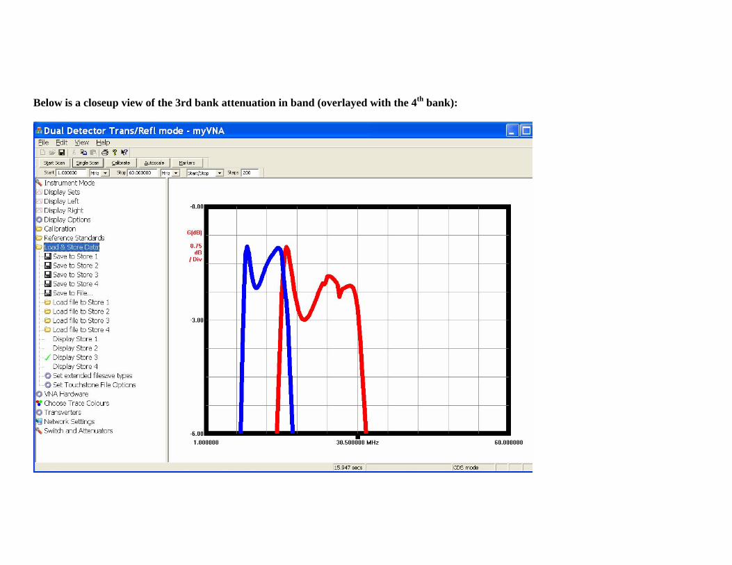
Below is a closeup view of the 3rd bank attenuation in band (overlayed with the 4th bank):
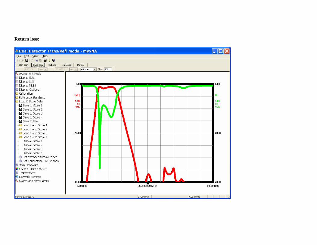
Return loss:
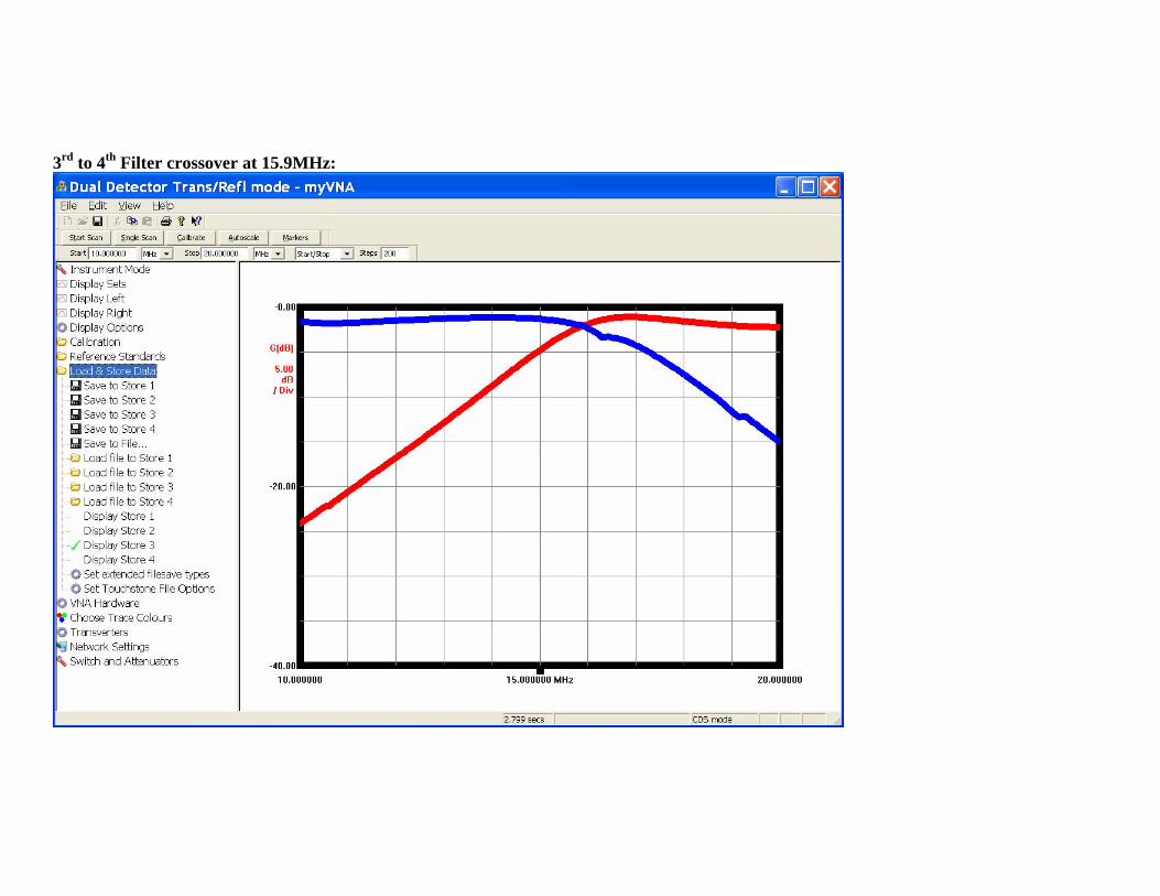
3rd to 4th Filter crossover at 15.9MHz:
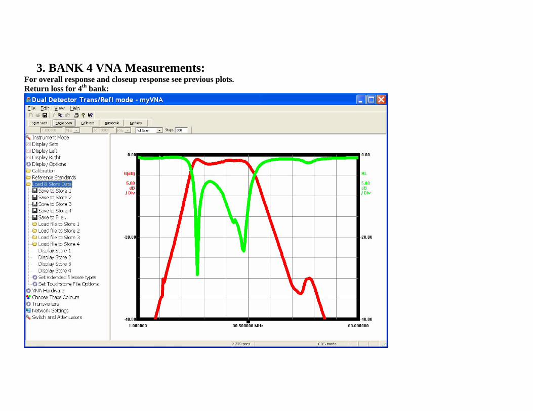
3. BANK 4 VNA Measurements: For overall response and closeup response see previous plots. Return loss for 4th bank:
4. Testing on V9 RX PowerSDR-IQ was used with the ExtIO_PMSDR.dll provided by Cesco to do the automatic band switching with adjustable crossover points. The crossover points were setup for 4, 8 and 16MHz. All the ham bands were spot checked using a HP8657A signal generator. The images were easily nulled to >60dB using the manual phase and gain adjustments in the PowerSDR-IQ setup for all Ham bands. Although I don’t exactly understand the reason for the offset in the bias point for the FST switches (from nominal 2.5V), it didn’t appear to make any difference in the overall RX performance. A NoiseCOM NC6107 was injected at the antenna input to check the overall flatness in RX amplitude response. The response was measured every 100KHz from 1MHz to 35MHz. The levels were very flat and typically with +-2dB on all HF bands. The -6dB points were measure to be at 1.4MHz and 33.5MHz. This makes the package excellent for full HF coverage.
Overall impressions:
1) Loss through the filters is very good. In all bank it has <3dB attenuation. This is very good for a RX filter.
2) Filter cross over points were verified. The best crossover points are:
4.1MHz, 8MHz, 15.9MHz almost exactly as spec’ed !!
3) Stop band attenuation not to bad considering the size and close proximity of the toroids. Some variance in ultimate rejection is dependent on the test configuration (i.e. which of the floating transformer connections are used as ground for the VNA). Actual operation using the V9 RX showed some aliased responses but not too bad considering the filter complexity.
4) Board is very compact and operates excellent on the V9 RX.
73, Mike Collins KF4BQ Treasure Island, FL