Boosting Scalability ofBoosting Scalability of InfiniBand ...
DELL POWER SOLUTIONS Reprinted from Dell Power Solutions, February 2006. Copyright © 2006 Dell Inc. All rights reserved. February 200644
DATABASES: ORACLE
When businesses start small and have little capital to
invest, they tend to keep their computer systems
simple, typically using a single database server and a stor-
age array to support a database. However, as a business
grows, this simple database configuration often cannot
handle the increased workload. At this point, businesses
typically upgrade their hardware by adding more CPUs
and other required resources or they add servers to create
a cluster. Increasing resources, or vertical scaling,gg is like
placing a temporary bandage on the system—it solves
the current situation of increased workload and resource
demand but does not address the possibility of future work-
load increase. Instead of adding more memory or CPUs to
the existing configuration, organizations can add servers
and configure them to function as a cluster to provide
load balancing, workload distribution, and availability—
a process known as horizontal scaling.
The growth potential for a vertically scalable system
is limited because it reaches a point at which the addition
of resources does not provide proportionally improved
results. In contrast, horizontal scalability enabled by
clustered hardware can distribute user workload among
multiple servers, or nodes. These nodes may be rela-
tively small and can use inexpensive standards-based
hardware, offering economical upgradeability options that
can enhance a single large system. In addition, clusters
offer both horizontal and vertical scalability, providing
further investment protection.
Understanding Oracle 10g0 RealgApplication ClustersOracle 10g Real Application Clusters (RAC) is designedg
to provide true clustering in a shared database environ-
ment. A RAC configuration comprises two or more nodes
supporting two or more database instances clustered
together through Oracle clusterware. Using Oracle’s cache
fusion technology, the RAC cluster can share resources
and balance workloads, providing optimal scalability
for today’s high-end computing environments. A typical
RAC configuration consists of the following:
BY ZAFAR MAHMOOD; ANTHONY FERNANDEZ; BERT SCALZO, PH.D.; AND MURALI VALLATH
Testing Oracle 10g RAC Scalability on Dell PowerEdge Servers and Dell/EMC Storage
Oracle® 10g Real Application Clusters (RAC) software running on standards-based Dell™
PowerEdge™ servers and Dell/EMC storage can provide a flexible, reliable platform
for a database grid. Administrators can scale the database easily and reliably simply
by adding nodes to the cluster. A team of engineers from Dell and Quest Software
ran benchmark tests against a Dell-based Oracle 10g® Release 1 RAC cluster to
demonstrate the scalability of this platform.
Related Categories:
Characterization
Oracle
Benchmark Factory
Quest Software
Scalable enterprise
Visit www.dell.com/powersolutions
for the complete category index.
DATABASES: ORACLE
www.dell.com/powersolutions Reprinted from Dell Power Solutions, February 2006. Copyright © 2006 Dell Inc. All rights reserved. DELL POWER SOLUTIONS 45
• A database instance running on each node• All database instances sharing a single physical database• Each database instance having common data and control files• Each database instance containing individual log files and undo
segments• All database instances simultaneously executing transactions
against the single physical database• Cache synchronization between user requests across various
database instances using the cluster interconnect
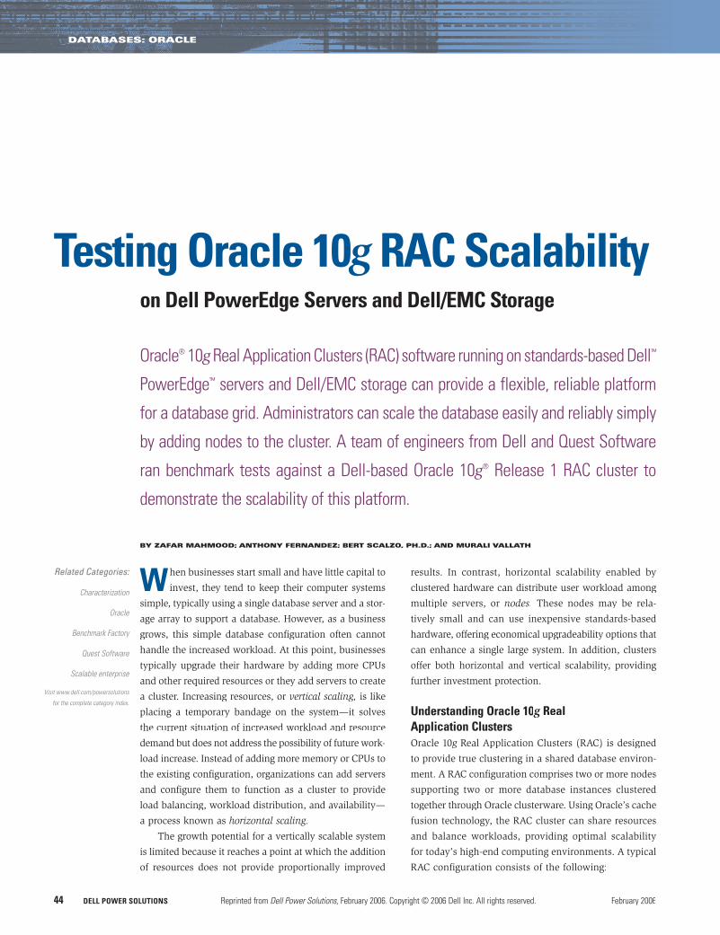
Figure 1 shows the components of a typical RAC cluster.
Oracle clusterwareOracle clusterware comprises three daemon processes: Oracle Cluster
Synchronization Services (CSS), Oracle Event Manager (EVM), and
Oracle Cluster Ready Services (CRS). This clusterware is designed
to provide a unified, integrated solution that enables scalability
of the RAC environment.
Cluster interconnectAn interconnect is a dedicated private network between the vari-
ous nodes in a cluster. The RAC architecture uses the cluster
interconnect for instance-to-instance block transfers by providing
cache coherency. Ideally, interconnects are Gigabit Ethernet
adapters configured to transfer packets of the maximum size
supported by the OS. Depending on the OS, the suggested pro-
tocols may vary; on clusters running the Linux® OS, the recom-
mended protocol is UDP.
Virtual IPTraditionally, users and applications have connected to the RAC
cluster and database using a public network interface. The network
protocol used for this connection has typically been TCP/IP. When
a node or instance fails in a RAC environment, the application is
unaware of failed attempts to make a connection because TCP/IP
can take more than 10 minutes to acknowledge such a failure, caus-
ing end users to experience unresponsive application behavior.
Virtual IP (VIP) is a virtual connection over the public interface.
If a node fails when an application or user makes a connection
using VIP, the Oracle clusterware—based on an event received from
EVM—will transfer the VIP address to another surviving instance.
Then, when the application attempts a new connection, two pos-
sible scenarios could ensue, depending on the Oracle 10g database g
features that have been implemented:
• If the application uses Fast Application Notification (FAN) calls,
Oracle Notification Services (ONS) will inform ONS running on
the client systems that a node has failed, and the application—
using an Oracle-provided application programming interface
(API)—can receive this notification and connect to one of the
other instances in the cluster. Such proactive notification mech-
anisms can help prevent connections to a failed node.• If the application attempts to connect using the VIP address
of the failed node, the connection will be refused because of
a mismatch in the hardware address and the application is
immediately notified of the failure.
Shared storageAnother important component of a RAC cluster is its shared storage,
which is accessed by all participating instances in the cluster. The
shared storage contains the data files, control files, redo logs, and
undo files. Oracle Database 10g supports three methods for storingg
files on shared storage: raw devices, Oracle Cluster File System
(OCFS), and Oracle Automatic Storage Management (ASM).
Raw devices. A raw device partition is a contiguous region of a
disk accessed by a UNIX® or Linux character-device interface. This
interface provides raw access to the underlying device, arranging
for direct I/O between a process and the logical disk. Therefore,
when a process issues a write command to the I/O system, the data
is moved directly to the device.
Oracle Cluster File System. OCFS is a clustered file system
developed by Oracle to provide easy data file management as well
Network switch
SSKY1
InterprocessCommunication (IPC)
Communication layer
Listeners | monitors
Clusterware
OS
VIP
ORADB1
SSKY2
IPC
Communication layer
Listeners | monitors
Clusterware
OS
VIP
ORADB2
G1 G2
G1 G2
G1 G2
G1 G2
Network switch
SSKY3
IPC
Communication layer
Listeners | monitors
Clusterware
OS
VIP
ORADB3
SSKY4
IPC
Communication layer
Listeners | monitors
Clusterware
OS
VIP
ORADB4
Public network
Cluster interconnect
G1 G2
G1 G2
SAN switch
Shared disk
Source: Oracle 10g RAC Grid, Services & Clustering by Murali Vallath, 2005.
Figure 1. Components within a typical Oracle 10g RAC clusterg
DATABASES: ORACLE
DELL POWER SOLUTIONS Reprinted from Dell Power Solutions, February 2006. Copyright © 2006 Dell Inc. All rights reserved. February 200646
as performance levels similar to raw devices. OCFS 1.0 supports only
database files to be stored on devices formatted using OCFS, while
OCFS 2.0 supports both Oracle and non-Oracle files. OCFS supports
both Linux and Microsoft® Windows® operating systems.
Oracle Automatic Storage Management. ASM is a storage
management feature introduced in Oracle Database 10g. ASM is
designed to integrate the file system and volume manager. Using
Oracle Managed Files (OMF) architecture, ASM distributes the I/O
load across all available resources to help optimize performance
and throughput.
Testing Oracle RAC environments for scalabilityThe primary advantages of Oracle RAC systems, apart from
improved performance, are availability and scalability. Availability
is enhanced with RAC because, if one of the nodes or the instances
in the cluster fails, the remainder of the instances would continue
to provide access to the physical database. Scalability is possible
because, when the user workload increases, users can access the
database from any of the available instances that have resources
available. Database administrators (DBAs) also can add nodes to
the RAC environment when the user base increases.
When organizations migrate to a RAC environment, best
practices recommend conducting independent performance tests
to determine the capacity of the cluster configured. Such tests can
help determine when a cluster will require additional instances
to accommodate a higher workload. To illustrate this, in August
and September 2005 engineers from the Dell Database and Appli-
cations team and Quest Software conducted benchmark tests
on Dell PowerEdge servers and Dell/EMC storage supporting
an Oracle 10g RAC database cluster. The results of these testsg
demonstrate the scalability of Dell PowerEdge servers running
Oracle RAC and ASM.
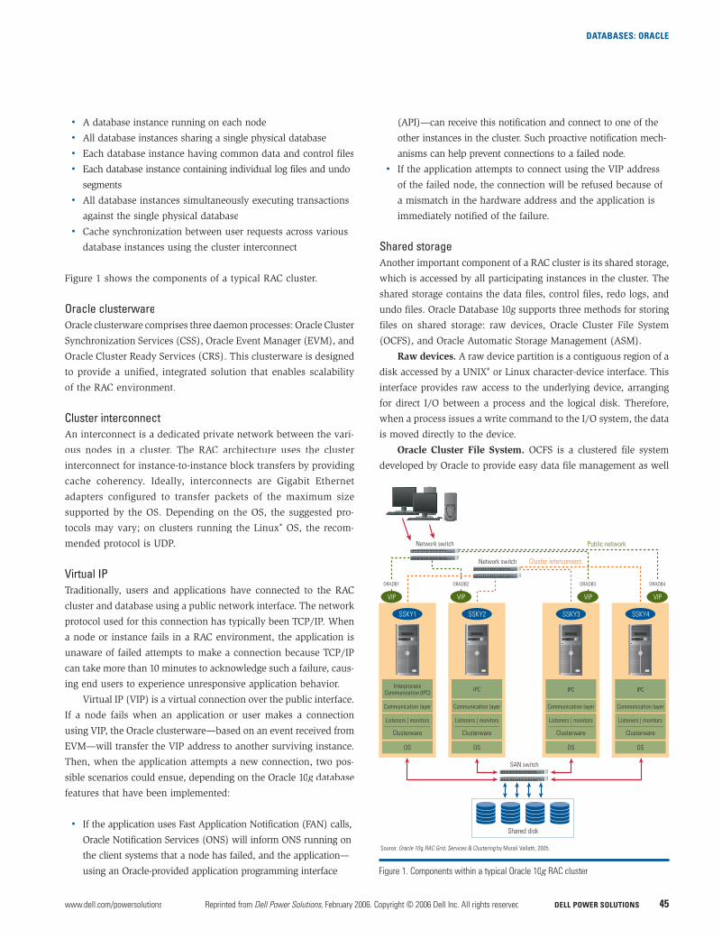
Figure 2 lists the hardware and software used in the test envi-
ronment, while Figure 3 describes the database configuration,
including the disk groups and tablespaces. Figure 4 shows the
layout of the cluster architecture.
Hardware Software
Oracle 10g RAC Dell PowerEdge 1850 servers, cluster nodes (10) each with: • Two Intel® Xeon® processors at 3.8 GHz • 4 GB of RAM • 1 Gbps* Intel NIC for the LAN • Two 1 Gbps LAN on Motherboards (LOMs) teamed for the private interconnect • Two QLogic QLA2342 HBAs • Dell Remote Access Controller • Two internal RAID-1 disks (73 GB 10,000 rpm) for the OS and Oracle Home
Benchmark Factory Dell PowerEdge 6650 servers, for Databases each with:servers (2) • Four Intel Xeon processors • 8 GB of RAM
Storage • Dell/EMC CX700 storage array • Dell/EMC Disk Array Enclosure with 30 disks (73 GB 15,000 rpm) • RAID Group 1: 16 disks with four 50 GB RAID-10 logical units (LUNs) for data and backup • RAID Group 2: 10 disks with two 20 GB LUNs for the redo logs • RAID Group 3: 4 disks with one 5 GB LUN for the voting disk, Oracle Cluster Repository (OCR), and spfiles • Two 16-port Brocade SilkWorm 3800 Fibre Channel switches • Eight paths configured to each logical volume
Network • 24-port Dell PowerConnect™ 5224 Gigabit Ethernet switch for the private interconnect • 24-port Dell PowerConnect 5224 Gigabit Ethernet switch for the public LAN
• Red Hat Enterprise Linux AS 4 QU1• EMC PowerPath 4.4• EMC Navisphere® agent • Oracle 10g R1 10.1.0.4• Oracle ASM 10.1.0.4• Oracle CRS 10.1.0.4• Linux bonding driver for the private interconnect• Dell OpenManage
• Microsoft Windows Server™ 2003 • Benchmark Factory application and agents• Spotlight on RAC
• EMC FLARE™ Code Release 16
*This term does not connote an actual operating speed of 1 Gbps. For high-speed transmission, connection to a Gigabit Ethernet server and network infrastructure is required.
• Linux binding driver used to team dual on-board NICs for the private interconnect
Figure 2. Hardware and software configuration for the test environment
Database Oracle Database 10g R1 10.1.04 Enterprise Edition
ASM disk groups SYSTEMDG: 50 GB DATADG: 50 GB INDEXDG: 50 GB REDO01DG: 20 GB REDO02 DG: 20 GB
All disk groups were created using the external redundancy option of ASM.
Tablespaces Quest_data in the DATADG disk group (40 GB) using the OMF feature Quest_index in the INDEXDG disk group (10 GB) using the OMF feature
All other database tablespaces were created in the SYSTEMDG disk group. Redo log files were created in the REDO01DG and REDO02DG disk groups
Figure 3. Database configuration for the test environment
Figure 4. Ten-node cluster architecture for the test environment
Dell PowerEdge 1850 servers
Brocade SilkWorm 3800Fibre Channel switch
G1 G2
Dell PowerConnect 5224Gigabit Ethernet switch
Interconnect switch
QLogic QLA2342HBAs (2)
Dell/EMC CX700 storage array
Two controllers withfour ports each
ASM disk groups
DATADG 50 GB
INDEXDG 50 GB
QUESTDG 50 GB
REDO01DG 20 GB
REDO02DG 20 GB
SYSTEMDG 50 GB
Brocade SilkWorm 3800Fibre Channel switch
Spotlight on RAC Benchmark Factory
Dell PowerConnect 5224Gigabit Ethernet switch
G1 G2
DATABASES: ORACLE
www.dell.com/powersolutions Reprinted from Dell Power Solutions, February 2006. Copyright © 2006 Dell Inc. All rights reserved. DELL POWER SOLUTIONS 47
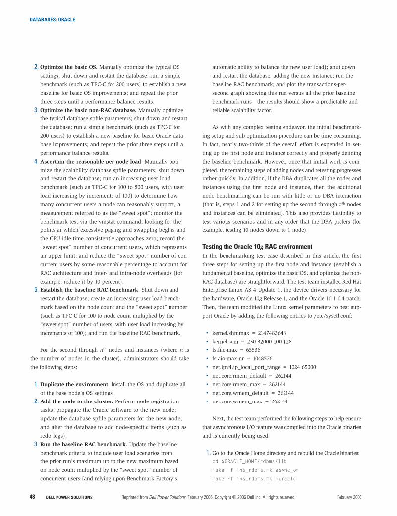
Benchmark Factory for DatabasesBenchmark Factory®y for Databases from Quest Software provides a®
simple yet robust graphical user interface (GUI), shown in Figure 5,
for creating, managing, and scheduling industry-standard data-
base benchmarks and real-world workload simulation. It helps
determine accurate production database hardware and software
configurations for optimal effectiveness, efficiency, and scal-
ability. Using Benchmark Factory, DBAs can address two chal-
lenging tasks: selecting a hardware architecture and platform
for deployment and determining the appropriate performance-
related service-level agreements.
While Benchmark Factory offers numerous industry-standard
benchmarks, the test team selected benchmarks similar to the TPC-C
benchmark from the Transaction Processing Performance Council
(TPC). This benchmark measures online transaction processing
(OLTP) workloads, combining read-only and update-intensive
transactions that simulate the activities found in complex OLTP
enterprise environments.
The benchmark tests simulated loads from 100 to 5,000 con-
current users in increments of 100, and these tests used a 10 GB
database created by Benchmark Factory. The goal was to ascertain
two critical data points: how many concurrent users each RAC node
could sustain, and whether the RAC cluster could scale both predict-
ably and linearly as additional nodes and users were added.
Spotlight on RACSpotlight® on RAC from Quest Software is a database monitor-
ing and diagnostic tool that extends the proven architecture and
intuitive GUI of the Spotlight on Oracle tool to RAC environments.
Spotlight on RAC is designed to provide a comprehensive yet com-
prehendible overview of numerous internal Oracle RAC settings
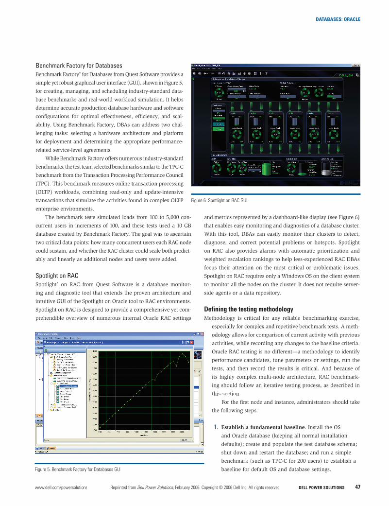
and metrics represented by a dashboard-like display (see Figure 6)
that enables easy monitoring and diagnostics of a database cluster.
With this tool, DBAs can easily monitor their clusters to detect,
diagnose, and correct potential problems or hotspots. Spotlight
on RAC also provides alarms with automatic prioritization and
weighted escalation rankings to help less-experienced RAC DBAs
focus their attention on the most critical or problematic issues.
Spotlight on RAC requires only a Windows OS on the client system
to monitor all the nodes on the cluster. It does not require server-
side agents or a data repository.
Defining the testing methodologyMethodology is critical for any reliable benchmarking exercise,
especially for complex and repetitive benchmark tests. A meth-
odology allows for comparison of current activity with previous
activities, while recording any changes to the baseline criteria.
Oracle RAC testing is no different—a methodology to identify
performance candidates, tune parameters or settings, run the
tests, and then record the results is critical. And because of
its highly complex multi-node architecture, RAC benchmark-
ing should follow an iterative testing process, as described in
this section.
For the first node and instance, administrators should take
the following steps:
1. Establish a fundamental baseline. Install the OS
and Oracle database (keeping all normal installation
defaults); create and populate the test database schema;
shut down and restart the database; and run a simple
benchmark (such as TPC-C for 200 users) to establish a
baseline for default OS and database settings.Figure 5. Benchmark Factory for Databases GUI
Figure 6. Spotlight on RAC GUI
DATABASES: ORACLE
DELL POWER SOLUTIONS Reprinted from Dell Power Solutions, February 2006. Copyright © 2006 Dell Inc. All rights reserved. February 200648
2. Optimize the basic OS. Manually optimize the typical OS
settings; shut down and restart the database; run a simple
benchmark (such as TPC-C for 200 users) to establish a new
baseline for basic OS improvements; and repeat the prior
three steps until a performance balance results.
3. Optimize the basic non-RAC database. Manually optimize
the typical database spfile parameters; shut down and restart
the database; run a simple benchmark (such as TPC-C for
200 users) to establish a new baseline for basic Oracle data-
base improvements; and repeat the prior three steps until a
performance balance results.
4. Ascertain the reasonable per-node load. Manually opti-
mize the scalability database spfile parameters; shut down
and restart the database; run an increasing user load
benchmark (such as TPC-C for 100 to 800 users, with user
load increasing by increments of 100) to determine how
many concurrent users a node can reasonably support, a
measurement referred to as the “sweet spot”; monitor the
benchmark test via the vmstat command, looking for the
points at which excessive paging and swapping begins and
the CPU idle time consistently approaches zero; record the
“sweet spot” number of concurrent users, which represents
an upper limit; and reduce the “sweet spot” number of con-
current users by some reasonable percentage to account for
RAC architecture and inter- and intra-node overheads (for
example, reduce it by 10 percent).
5. Establish the baseline RAC benchmark. Shut down and
restart the database; create an increasing user load bench-
mark based on the node count and the “sweet spot” number
(such as TPC-C for 100 to node count multiplied by the
“sweet spot” number of users, with user load increasing by
increments of 100); and run the baseline RAC benchmark.
For the second through nth nodes and instances (where n isn
the number of nodes in the cluster), administrators should take
the following steps:
1. Duplicate the environment. Install the OS and duplicate all
of the base node’s OS settings.
2. Add the node to the cluster. Perform node registration
tasks; propagate the Oracle software to the new node;
update the database spfile parameters for the new node;
and alter the database to add node-specific items (such as
redo logs).
3. Run the baseline RAC benchmark. Update the baseline
benchmark criteria to include user load scenarios from
the prior run’s maximum up to the new maximum based
on node count multiplied by the “sweet spot” number of
concurrent users (and relying upon Benchmark Factory’s
automatic ability to balance the new user load); shut down
and restart the database, adding the new instance; run the
baseline RAC benchmark; and plot the transactions-per-
second graph showing this run versus all the prior baseline
benchmark runs—the results should show a predictable and
reliable scalability factor.
As with any complex testing endeavor, the initial benchmark-
ing setup and sub-optimization procedure can be time-consuming.
In fact, nearly two-thirds of the overall effort is expended in set-
ting up the first node and instance correctly and properly defining
the baseline benchmark. However, once that initial work is com-
pleted, the remaining steps of adding nodes and retesting progresses
rather quickly. In addition, if the DBA duplicates all the nodes and
instances using the first node and instance, then the additional
node benchmarking can be run with little or no DBA interaction
(that is, steps 1 and 2 for setting up the second through nth nodes
and instances can be eliminated). This also provides flexibility to
test various scenarios and in any order that the DBA prefers (for
example, testing 10 nodes down to 1 node).
Testing the Oracle 10g0 RAC environmentgIn the benchmarking test case described in this article, the first
three steps for setting up the first node and instance (establish a
fundamental baseline, optimize the basic OS, and optimize the non-
RAC database) are straightforward. The test team installed Red Hat
Enterprise Linux AS 4 Update 1, the device drivers necessary for
the hardware, Oracle 10g Release 1, and the Oracle 10.1.0.4 patch.g
Then, the team modified the Linux kernel parameters to best sup-
port Oracle by adding the following entries to /etc/sysctl.conf:
• kernel.shmmax = 2147483648• kernel.sem = 250 32000 100 128• fs.file-max = 65536• fs.aio-max-nr = 1048576• net.ipv4.ip_local_port_range = 1024 65000• net.core.rmem_default = 262144• net.core.rmem_max = 262144• net.core.wmem_default = 262144• net.core.wmem_max = 262144
Next, the test team performed the following steps to help ensure
that asynchronous I/O feature was compiled into the Oracle binaries
and is currently being used:
1. Go to the Oracle Home directory and rebuild the Oracle binaries:
cd $ORACLE_HOME/rdbms/lib
make -f ins_rdbms.mk async_on
make -f ins_rdbms.mk ioracle
DATABASES: ORACLE
www.dell.com/powersolutions Reprinted from Dell Power Solutions, February 2006. Copyright © 2006 Dell Inc. All rights reserved. DELL POWER SOLUTIONS 49
2. Set the necessary spfile parameter settings:
disk_asynch_io = true
filesystemio_options = setall
The default value of disk_asynch_io is “true.” The “setall”
value for filesystemio_options enables both asynchronous and
direct I/O.
Note: In Oracle 10g Release 2, asynchronous I/O is compiledg
in by default.
The test team then created the RAC database and initial instance
using Oracle Database Configuration Assistant (DBCA), selecting
parameter settings suited for the proposed maximum scalability
(10 nodes). Finally, the team manually made the following spfile
adjustments:
• cluster_database = true• cluster_database_instances = 10• db_block_size = 8192• processes = 16000• sga_max_size = 1500m• sga_target = 1500m• pga_aggregate_target = 700m• db_writer_processes = 2• open_cursors = 00• optimizer_index_caching = 80• optimizer_index_cost_adj = 40
The primary goal was to consume as much System Global Area
(SGA) memory as possible within the 32-bit OS limit (about 1.7 GB).
Because the cluster servers had only 4 GB of RAM each, allocating
half of the memory to Oracle was sufficient—the remaining memory
was shared by the OS and the thousands of dedicated Oracle server
processes that the benchmark created as its user load.
Finding the “sweet spot”The next step was to ascertain the reasonable per-node load that the
cluster servers could accommodate. This is arguably the most critical
aspect of the entire benchmark testing process—especially for RAC
environments with more than just a few nodes. The test team initially
ran the benchmark on the single node without monitoring the test
via the vmstat command. Thus, simply looking at the transactions-
per-second graph in the Benchmark Factory GUI yielded a deceiving
conclusion that the “sweet spot” was 700 users per node. Although
the transactions per second continued to increase up to 700 users,
the OS was overstressed and exhibited minimal thrashing charac-
teristics at about 600 users. Moreover, the test team did not temper
that value by reducing for RAC overhead.
The end result was that the first attempt at running a series
of benchmarks for 700 users per node did not scale reliably or
predictably beyond four servers. Because each server was pushed
to a near-thrashing threshold by the high per-node user load, the
nodes did not have sufficient resources to communicate in a timely
fashion for inter- and intra-node messaging. Thus, the Oracle data-
base assumed that the nodes were either down or non-respondent.
Furthermore, the Oracle client and server-side load balancing feature
allocates connections based on which nodes are responding, so
the user load per node became skewed in this first test and then
exceeded the per-node “sweet spot” value. For example, when the
team tested 7,000 users for 10 nodes, some nodes appeared down to
the Oracle database and thus the load balancer simply directed all
the sessions across whichever nodes were responding. As a result,
some of the nodes tried to handle far more than 700 users—and
this made the thrashing increase.
Note: This problem should not occur in Oracle Database 10g
Release 2. With the runtime connection load-balancing feature and
FAN technology, the Oracle client will be proactively notified regard-
ing the resource availability on each node, and the client can place
connections on instances that have more resources. Load balancing
can be performed based on either connections or response time.
With a valuable lesson learned by the first test attempt, the
test team made two major improvements. First, they reevaluated
the “sweet spot” number by carefully monitoring the single-node
test (in which user load increased from 100 to 800) for the onset
of excessive paging, swapping, or a consistent CPU idle time near
zero. The team determined that the “sweet spot” number was
actually 600 users, not 700. They then reduced that number to 500
users to accommodate overhead for the RAC architecture, which
would require approximately 15 percent of the system resources.
This amount is not necessarily a recommendation for all RAC imple-
mentations; the test team used this amount to help yield a positive
scalability experience for the next set of benchmarking tests. A less
conservative “sweet spot” number could have been used if the team
were able to keep repeating the tests until a definitive reduction
percentage could be factually derived. Instead, the test team chose
a “sweet spot” value that they expected would work well yet would
not overcompensate. In addition, the team used the load-balancing
feature of Benchmark Factory—which allocates one-nth of the jobs
to each node (where n is the number of nodes in the cluster)—ton
help ensure that the number of users running on any given node
never exceeds the “sweet spot” value.
Increasing the user load to determine scalability With the “sweet spot” user load identified and guaranteed through
load balancing, the test team then ran the benchmark on the
cluster nodes as follows:
• One node: 100 to 500 users• Two nodes: 100 to 1,000 users
DATABASES: ORACLE
DELL POWER SOLUTIONS Reprinted from Dell Power Solutions, February 2006. Copyright © 2006 Dell Inc. All rights reserved. February 200650
• Four nodes: 100 to 2,000 users• Six nodes: 100 to 3,000 users• Eight nodes: 100 to 4,000 users• Ten nodes: 100 to 5,000 users
For each scenario, the workload was increased in increments
of 100 users. The Benchmark Factory default TPC-C-like test itera-
tion requires about four minutes for a given user load. Therefore,
for the single node with five user loads, the overall benchmark test
run required 20 minutes.
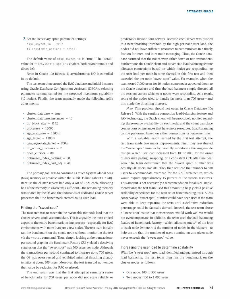
During the entire testing process, the load was moni-
tored using Spotlight on RAC to identify any problems.
As shown in Figure 7, when the four-node tests were
conducted, Spotlight on RAC identified that CPUs on
node racdb1 and racdb3 reached 84 percent and 76 per-
cent, respectively. This high CPU utilization probably was
caused by a temporary overload of users on these servers
and the ASM response time. To address this problem, the
test team increased the SHARED_POOL and LARGE_POOL
parameters on the ASM instance from their default values
of 32 MB and 12 MB, respectively, to 67 MB each. They
then ran the four-node test again, and none of the nodes
experienced excessive CPU utilization. This was the only
parameter change the team made to the ASM instance.
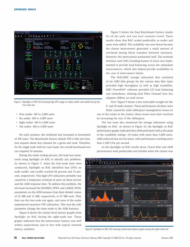
Figure 8 shows the cluster-level latency graphs from
Spotlight on RAC during the eight-node test. These
graphs indicated that the interconnect latency was well
within expectations and in line with typical network
latency numbers.
Figure 9 shows the final Benchmark Factory results
for all the node and user load scenarios tested. These
results show that RAC scaled predictably as nodes and
users were added. The scalability was near linear because
the cluster interconnect generated a small amount of
overhead during block transfers between instances.
However, the interconnect performed well. The network
interface card (NIC) bonding feature of Linux was imple-
mented to provide load balancing across the redundant
interconnects, which also helped provide availability in
the case of interconnect failure.
The Dell/EMC storage subsystem that consisted
of six ASM disk groups for the various data files types
provided high throughput as well as high scalability.
EMC PowerPath® software provided I/O load balancing
and redundancy utilizing dual Fibre Channel host bus
adapters (HBAs) on each server.
Note: Figure 9 shows a few noticeable troughs for the
8- and 10-node clusters. These performance declines were
likely caused by undo tablespace management issues on
one of the nodes in the cluster; these issues were later resolved
by increasing the size of the tablespace.
The test team also monitored the storage subsystem using
Spotlight on RAC. As shown in Figure 10, the Spotlight on RAC
performance graphs indicated that ASM performed well at the peak
of the scalability testing—10 nodes with more than 5,000 users.
ASM achieved fast service times, with performance reaching more
than 2,500 I/Os per second.
As the Spotlight on RAC results show, Oracle RAC and ASM
performance were predictable and reliable when the cluster was
Figure 7. Spotlight on RAC GUI showing high CPU usage on nodes racdb1 and racdb3 during the four-node test
Figure 8. Spotlight on RAC GUI showing cluster-level latency graphs during the eight-node test
DATABASES: ORACLE
www.dell.com/powersolutions Reprinted from Dell Power Solutions, February 2006. Copyright © 2006 Dell Inc. All rights reserved. DELL POWER SOLUTIONS 51
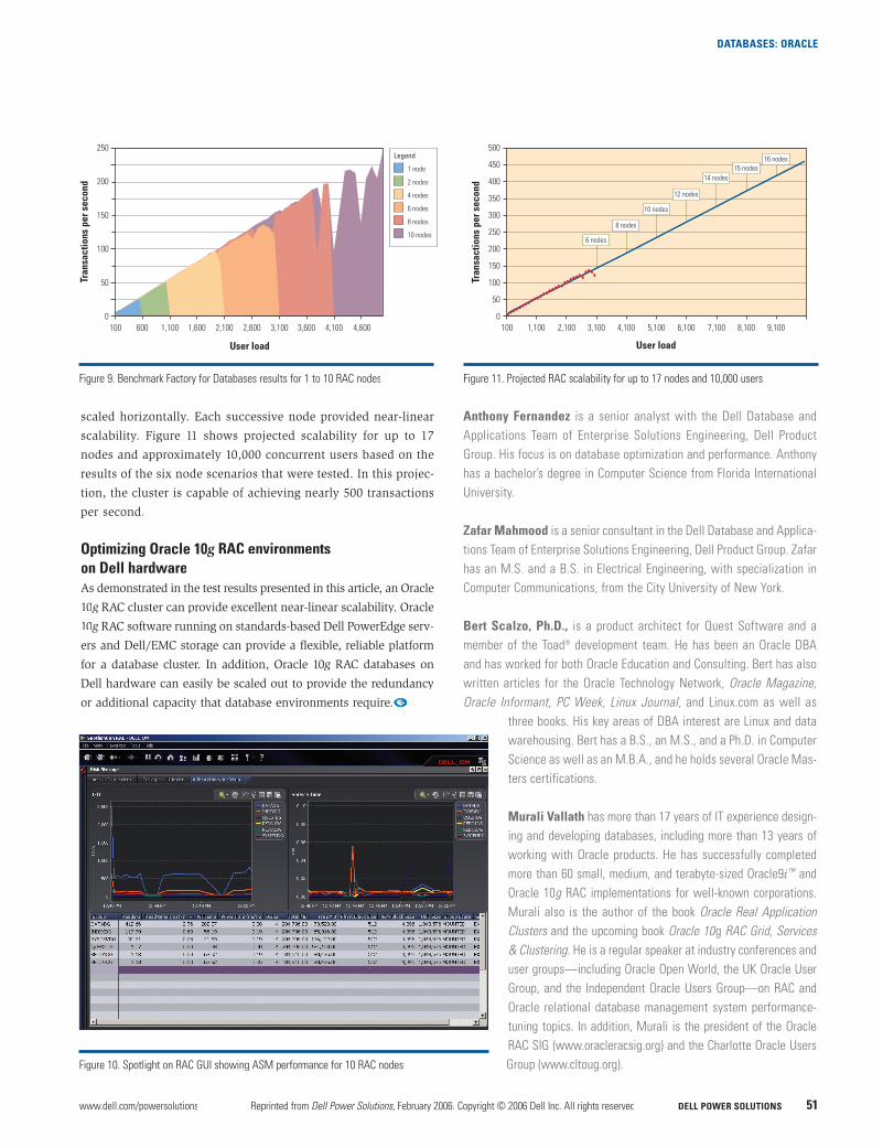
scaled horizontally. Each successive node provided near-linear
scalability. Figure 11 shows projected scalability for up to 17
nodes and approximately 10,000 concurrent users based on the
results of the six node scenarios that were tested. In this projec-
tion, the cluster is capable of achieving nearly 500 transactions
per second.
Optimizing Oracle 10g0 RAC environmentsgon Dell hardwareAs demonstrated in the test results presented in this article, an Oracle
10g RAC cluster can provide excellent near-linear scalability. Oracleg
10g RAC software running on standards-based Dell PowerEdge serv-g
ers and Dell/EMC storage can provide a flexible, reliable platform
for a database cluster. In addition, Oracle 10g RAC databases ong
Dell hardware can easily be scaled out to provide the redundancy
or additional capacity that database environments require.
Anthony Fernandez is a senior analyst with the Dell Database and Applications Team of Enterprise Solutions Engineering, Dell Product Group. His focus is on database optimization and performance. Anthony has a bachelor’s degree in Computer Science from Florida International University.
Zafar Mahmood is a senior consultant in the Dell Database and Applica-tions Team of Enterprise Solutions Engineering, Dell Product Group. Zafar has an M.S. and a B.S. in Electrical Engineering, with specialization in Computer Communications, from the City University of New York.
Bert Scalzo, Ph.D., is a product architect for Quest Software and a member of the Toad® development team. He has been an Oracle DBA and has worked for both Oracle Education and Consulting. Bert has also written articles for the Oracle Technology Network, Oracle Magazine,Oracle Informant, PC Week, Linux Journal, and Linux.com as well as
three books. His key areas of DBA interest are Linux and data warehousing. Bert has a B.S., an M.S., and a Ph.D. in Computer Science as well as an M.B.A., and he holds several Oracle Mas-ters certifications.
Murali Vallath has more than 17 years of IT experience design-ing and developing databases, including more than 13 years of working with Oracle products. He has successfully completed more than 60 small, medium, and terabyte-sized Oracle9i ™ and Oracle 10g RAC implementations for well-known corporations. Murali also is the author of the book Oracle Real Application Clusters and the upcoming book Oracle 10g RAC Grid, Services & Clustering. He is a regular speaker at industry conferences and user groups—including Oracle Open World, the UK Oracle User Group, and the Independent Oracle Users Group—on RAC and Oracle relational database management system performance-tuning topics. In addition, Murali is the president of the Oracle RAC SIG (www.oracleracsig.org) and the Charlotte Oracle Users Group (www.cltoug.org).Figure 10. Spotlight on RAC GUI showing ASM performance for 10 RAC nodes
Figure 11. Projected RAC scalability for up to 17 nodes and 10,000 users
6 nodes
8 nodes
10 nodes
12 nodes
14 nodes15 nodes
16 nodes500
450
400
350
300
250
200
150
100
50
0
Tran
sact
ions
per
sec
ond
100 1,100 2,100 3,100 4,100 5,100 6,100 7,100 8,100 9,100
User load
250
200
150
100
50
0
Tran
sact
ions
per
sec
ond
100 600 1,100 1,600 2,100 2,600 3,100 3,600 4,100 4,600
User load
Legend
1 node
2 nodes
4 nodes
6 nodes
8 nodes
10 nodes
Figure 9. Benchmark Factory for Databases results for 1 to 10 RAC nodes