Testing of Portable Radios in a Fire Fighting Environment
24
Testing of Portable Radios in a Fire Fighting Environment W. D. Davis M. K. Donnelly M. J. Selepak NIST Technical Note 1477
Transcript of Testing of Portable Radios in a Fire Fighting Environment
Testing of Portable Radios in a Fire Fighting Environment
W. D. Davis M. K. Donnelly M. J. Selepak
NIST Technical Note 1477


NIST Technical Note 1477
Testing of Portable Radios in a Fire Fighting Environment
W. D. Davis M. K. Donnelly M. J. Selepak Building and Fire Research Laboratory
August 2006
U.S. Department of Commerce Carlos M. Gutierrez, Secretary Technology Administration Robert Cresanti, Under Secretary for Technology National Institute of Standards and Technology William Jeffrey, Director

iii
Certain commercial entities, equipment, or materials may be identified in this document in order to describe an experimental procedure or concept adequately. Such identification is not intended to imply recommendation or endorsement by the National Institute of Standards and Technology, nor is it intended to imply that the entities, materials, or equipment are necessarily the best available for the purpose.
National Institute of Standards and Technology Technical Note 1477 Natl. Inst. Stand. Technical Note 1477, 15 pages (August 2006) CODEN: N

iv
Table of Contents ABSTRACT................................................................................................................................... v INTRODUCTION......................................................................................................................... 1
Table 1 Thermal Classes ............................................................................................... 1 Radio Testing............................................................................................................................. 1
Figure 1 Diagram of Fire Equipment Evaluator (FEE) ............................................... 2 Testing Procedures.................................................................................................................... 2
Figure 2 Plot of Temperatures inside and outside of pocket ........................................ 3 Figure 3 Radio inside turnout coat pocket with speaker/microphone ......................... 4 Figure 4 Pocket inside FEE for testing. .......................................................................... 5
RESULTS ...................................................................................................................................... 6 Testing with Radio in Turnout Coat Pocket........................................................................... 6
Table 2 Testing inside turnout coat pocket, air velocity 0.9 m/s ................................. 7 Table 3 Testing inside Turnout Coat Pocket, Variations ............................................. 8
Testing of Radios without Turnout Coat Pocket Protection................................................. 8 Table 4 Thermal Class I – 100 ºC for 25 min soak, velocity 0.9 m/s ........................... 9 Table 5 Thermal Class II – 160 ºC for 15 min soak, velocity 0.9 m/s........................ 10 Table 6 Temperatures beyond 160 ºC, for 5 min soak, velocity 0.9 m/s ................... 10
Speaker/Microphone testing .................................................................................................. 10 Figure 5 Radio Transmission Signal for Radio C during Thermal Class II Soak ..... 12 Table 7 External Speaker/Microphone Testing, velocity 0.9 m/s .............................. 13
DISCUSSION .............................................................................................................................. 13 CONCLUSION ........................................................................................................................... 14 REFERENCES............................................................................................................................ 16 ACKNOWLEDGEMENT.......................................................................................................... 17
v
ABSTRACT Handheld portable radios are one of the critical electronic devices that firefighters and other first responders use during emergency response. These radios must operate in severe environmental conditions while maintaining acceptable radio communication. This paper focuses on the thermal environment that radios would be expected to withstand while being used in building firefighting operations. The thermal classes for electronic equipment defined in an earlier paper (Donnelly, et al, 2006) are applied to investigate the performance of emergency responder radios. Current National Fire Protection Association (NFPA) standards for radios are reviewed and recommendations for establishing performance standards are presented. The need for providing additional protection from the thermal environment is documented.
1
INTRODUCTION The National Fire Protection Association (NFPA) standards for portable radios and other two-way mobile communication equipment are not specific as to temperature, heat flux and other environmental conditions. The devices are included in the NFPA 1221 standard for Installation, Maintenance and Use of Emergency Services Communications Systems (NFPA 1221, 2002 Ed.). Sections 8.3.5 and 8.3.6 summarize general equipment usage. The only requirements pertaining to the fire environment are section 8.3.5.4, which states “Mobile radios and associated equipment shall be manufactured for the environment in which they are to be used”, and section 8.3.6.2 which states “Portable radios shall be manufactured for the environment in which they are to be used and shall be of a size and construction to allow their operation with the use of one hand.” The NFPA standard is not specific with regards to the details of the “environment” in which the radios are to be used. No testing procedures or performance criteria are outlined. This paper applies the Thermal Classes, see Table 1, that were developed in an earlier study (Donnelly, et al, 2006) to define the environment and performance criteria for portable handheld radios. Radios currently in use by firefighters were tested using the Fire Equipment Evaluator (FEE) to determine their current capability to withstand conditions as severe as Thermal Class III. The results will be used to develop test methods and recommendations that will be submitted to NFPA 1221 for standards development for portable radios.
Table 1 Thermal Classes
Thermal Class Maximum
Time (min) Maximum
Temperature (°C)/(°F)
Maximum Flux (kW/m2)
I 25 100/212 1 II 15 160/320 2 III 5 260/500 10 IV <1 >260/500 >10
Radio Testing Three models of radios from three different manufacturers were selected for this study. They will be identified in this report as Radio A, Radio B and Radio C. The radios were marketed for use by firefighters and other first responders. The radios ranged in price from approximately $800 each to $2500 each. The radios tested for this project were a sampling of the many makes and models that are available to first responders. The selected radios are commonly used and represent a variety of price ranges. The goal of this study was not to compare and rank the performance of individual radios, but rather to evaluate the general performance of portable radios at elevated thermal conditions and to identify shortcomings and suggest standards for the radios.
2
All of the radios tested for this investigation listed their maximum operating temperatures at 60 ºC (140 ºF). The frequency stability for the radio signal was guaranteed to 60 ºC (140 ºF) as well. The radios, however, are marketed to and used by firefighters in firefighting situations, so it is reasonable to expect that they may be used at temperatures above 60 ºC (140 ºF). Firefighters routinely spend time at temperatures up to 100 ºC (212°F), and often encounter much higher temperatures such as the peak conditions of Thermal Class III. Radio operation may be most crucial when the firefighter is experiencing an emergency situation, possibly trapped at elevated temperatures, and the radio would be instrumental in calling for assistance. As shown in Table 1, which lists the thermal classes, electronic equipment should be able to withstand a minimum of 100 ºC (212°F) for up to 25 minutes in order to survive Thermal Class I conditions while Thermal Class III conditions would require the electronic equipment to survive 260 °C (500 °F) for five minutes.
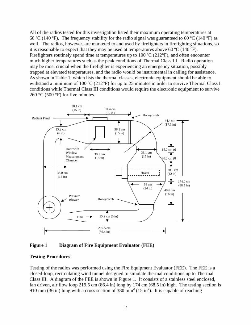
Figure 1 Diagram of Fire Equipment Evaluator (FEE) Testing Procedures Testing of the radios was performed using the Fire Equipment Evaluator (FEE). The FEE is a closed-loop, recirculating wind tunnel designed to simulate thermal conditions up to Thermal Class III. A diagram of the FEE is shown in Figure 1. It consists of a stainless steel enclosed, fan driven, air flow loop 219.5 cm (86.4 in) long by 174 cm (68.5 in) high. The testing section is 910 mm (36 in) long with a cross section of 380 mm2 (15 in2). It is capable of reaching
15.2 cm (6 in)
38.1 cm (15 in)
174.0 cm (68.5 in)
30.5 cm (12 in)
38.1 cm (15 in) 91.4 cm
(36 in)
33.0 cm (13 in)
38.1 cm (15 in)
61 cm (24 in)
15.2 cm (6
20.3 cm (8
40.6 cm (16 in)
44.4 cm (17.5 in)
219.5 cm (86.4 in)
15.2 cm (6 in)
Door with Window Measurement Chamber
Heater
Pressure Blower
Radiant Panel
Honeycomb
38.1 cm (15 in)
Honeycomb
Flow

3
temperatures up to 300 ºC (572 °F) and velocities from 0.5 m/s to 2.0 m/s. Temperature measurements inside the FEE were made using type K (Chromel-Alumel) thermocouples, each with a bead diameter of 1.0 mm ± 0.2mm. A bidirectional probe was used for the velocity measurement. Details of the FEE can be found in Donnelly, et al, 2006. For the elevated temperature tests, the radio was placed into the test tunnel at ambient temperature, subjected to a heat-up time reaching the target temperature for the particular thermal class and then maintained at this temperature for the time period specified for that thermal class. The radio performance was also monitored during the cool down period. Heating of the radio at constant temperature for a prescribed time period will be referred to as “soak” throughout the remainder of the paper. This would simulate a firefighter entering a structure and encountering progressively higher temperatures before reaching the maximum temperature, performing firefighter tasks at this maximum temperature for a period of time, and then exiting the high temperature region. Actual times encountered by a firefighter would depend on the building geometry and conditions within the building. The heat-up time varied depending on the soak temperature, but was held constant for all tests at the same soak temperature. See Figure 2 for a temperature profile displaying a typical heat-up time for Thermal Class III conditions.
0
50
100
150
200
250
300
0 250 500 750 1000 1250 1500
center of duct8 cm above centerline8 cm below centerlineinside pocket,in front of radioinside pocket,attached to radio
Tem
pera
ture
(o C)
Time (s)
End SoakStart Soak
Figure 2 Plot of Temperatures inside and outside of pocket. Radios tested inside the FEE were placed in the test section where they were visible through the access door window. The radios were suspended by the radio belt clip from a 50 mm wide Kevlar strap with the front of the radio (speaker and microphone) facing the airflow. They were placed with the long side along the vertical at a height such that the center of the radio was

4
centered, 190 mm from the walls of the test section. The radio hung at a slight angle of approximately 20 degrees from vertical, with the top tilted towards the airflow. Testing was also performed with the radios protected inside of a turnout gear style pocket. When portable radios are carried into firefighting environments, the radios are often worn clipped close to the body underneath the turnout gear coat, or placed in pockets located on the outside of the turnout gear coat where they are protected from direct heating by the pocket as displayed on a mannequin in Figure 3.
Figure 3 Radio inside turnout coat pocket with speaker/microphone To investigate the operation of these protected radios, a pocket was constructed and used for testing. The pocket was fabricated by a company that produces firefighter turnout gear. It was made from 2.5 x 10⁻² kg/m2 (7.5 oz/yd2) PBI Gold, material that is a blend of 40 % polybenzimidizole and 60 % Kevlar. The pocket measures 100 mm wide by 90 mm deep and is 220 mm tall. It is open at the top for radio insertion, with a flap to cover the top of the radio. Figure 3 shows the pocket suspended from the Kevlar strap inside the FEE. The radio was placed inside the pocket for testing.
5
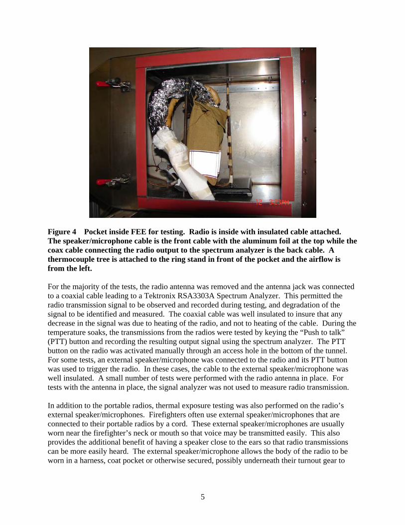
Figure 4 Pocket inside FEE for testing. Radio is inside with insulated cable attached. The speaker/microphone cable is the front cable with the aluminum foil at the top while the coax cable connecting the radio output to the spectrum analyzer is the back cable. A thermocouple tree is attached to the ring stand in front of the pocket and the airflow is from the left. For the majority of the tests, the radio antenna was removed and the antenna jack was connected to a coaxial cable leading to a Tektronix RSA3303A Spectrum Analyzer. This permitted the radio transmission signal to be observed and recorded during testing, and degradation of the signal to be identified and measured. The coaxial cable was well insulated to insure that any decrease in the signal was due to heating of the radio, and not to heating of the cable. During the temperature soaks, the transmissions from the radios were tested by keying the “Push to talk” (PTT) button and recording the resulting output signal using the spectrum analyzer. The PTT button on the radio was activated manually through an access hole in the bottom of the tunnel. For some tests, an external speaker/microphone was connected to the radio and its PTT button was used to trigger the radio. In these cases, the cable to the external speaker/microphone was well insulated. A small number of tests were performed with the radio antenna in place. For tests with the antenna in place, the signal analyzer was not used to measure radio transmission. In addition to the portable radios, thermal exposure testing was also performed on the radio’s external speaker/microphones. Firefighters often use external speaker/microphones that are connected to their portable radios by a cord. These external speaker/microphones are usually worn near the firefighter’s neck or mouth so that voice may be transmitted easily. This also provides the additional benefit of having a speaker close to the ears so that radio transmissions can be more easily heard. The external speaker/microphone allows the body of the radio to be worn in a harness, coat pocket or otherwise secured, possibly underneath their turnout gear to

6
protect the radio. Often it is only the external speaker/microphone that is exposed to the extreme thermal environment, making this the part most vulnerable to malfunction. To investigate the possible problems, tests were conducted using the FEE. Each speaker/microphone was placed in the test section, with a cord connecting it to a radio located in ambient conditions outside of the FEE. Each radio was tested with its own proprietary speaker/microphone designed for use with the radio. The cords connecting the speaker/microphones to the radios were not thermally insulated, which provided a realistic test of the speaker/microphone/cord system. The ruggedized version of the speaker/microphone was used when available. The speaker/microphones were suspended from the same Kevlar strap used to support the radios. The strap was lowered so that the center of the speaker was located at the center of the test chamber cross section. The portable radio was located outside of the test chamber, and the cable connecting the radio to the speaker/microphone was well insulated. Transmission from the speaker/microphones was initiated the same way as it was for the radios, by keying the PTT button on the microphone, using the access hole in the bottom of the tunnel. The radios and speaker/microphones tested were subjected to thermal exposures consistent with the maximum time and temperature for the Thermal Classes shown in Table 1. Testing was performed with the radios both inside a turnout gear pocket and exposed to the airflow. Testing of the external speaker/microphones was conducted with the speaker/microphones exposed to the airflow. Radios and speaker/microphones that did not suffer permanent damage were reused for repeat tests. The majority of the tests were performed at an air flow velocity of 0.9 m/s. This velocity was chosen to represent a typical human walking speed or a flow velocity that might be experienced with Thermal Class III exposure. RESULTS Testing with Radio in Turnout Coat Pocket Elevated temperature tests were performed using the FEE with the portable radios placed inside the turnout gear pocket. Two thermocouples were located inside the pocket. One monitored the air temperature directly in front of the radio, and the other was attached to the body of the radio. The pocket was able to provide significant thermal protection to the radio, with the air inside the pocket remaining more than 75 ºC cooler than the air inside the rest of the tunnel, when the flow rate was 0.9 m/s. Figure 2 is an example of the thermal difference between the pocket air and the tunnel air for a 260 ºC temperature soak with airflow 0.9 m/s. When the FEE air speed was increased to 2 m/s, the air inside the pocket still remained at least 57 ºC cooler. The air temperature inside the pocket was continually increasing during the temperature soaks, so the difference between the pocket air temperature and the tunnel temperature was even greater at the start of the soaks. The test results are listed in Table 2. The protection provided by the turnout gear pocket kept the radio temperatures low enough for the radios to survive even the severity of the class III tests. Radio A worked well throughout the class II tests and did not have any evident damage. Radio A also received and transmitted during the class III testing, suffering only some slight melting deformation to the outer casing and buttons. Radio B was able to survive all of the

7
temperature soaks attempted during the pocket testing. Transmission and reception of the signals were clear. There was no damage evident to the body of radio B during the pocket tests. Radio C was also able to transmit and receive at the test conditions when located inside the pocket. Some variations on the basic testing conditions were performed and the results are shown in Table 3. Tests were performed at the Thermal Class III condition using radios A and B with the regular antenna connected, instead of the shielded cable connected to the analyzer. The antenna was sticking up out of the pocket and was directly exposed to the elevated temperatures. For these tests, no signal was recorded using the analyzer. Transmission and reception were measured qualitatively by the FEE operator. For both Radio A and Radio B, transmission and reception were considered to be the same as when not exposed to elevated temperature conditions for the duration of the soak. Some damage did occur to the antennas as a result of their exposure to the heat outside of the pocket. For Radio A, there was some slight melting and deformation of the antenna. The antenna for Radio B was very deformed curving approximately 90 degrees and remained permanently bent over after the test. However, even with the bending of the antenna, transmission and reception worked in the laboratory setting. Table 2 Testing inside turnout coat pocket, air velocity 0.9 m/s Radio Temp
(°C) Time Soak
(min) Survive
Soak Notes
A 160 15 Yes No damage to radio evident A 160 15 Yes No damage to radio evident A 260 5 Yes Some melting, deformation of PTT button and
display B 100 25 Yes No damage to radio evident B 100 25 Yes No damage to radio evident B 160 15 Yes No damage to radio evident B 160 15 Yes No damage to radio evident B 260 5 Yes No damage to radio evident B 260 5 Yes No damage to radio evident C 100 25 Yes No damage to radio evident C 160 15 Yes No damage to radio evident C 160 15 Yes No damage to radio evident C 260 5 Yes No damage to radio evident C 260 5 Yes No damage to radio evident
8
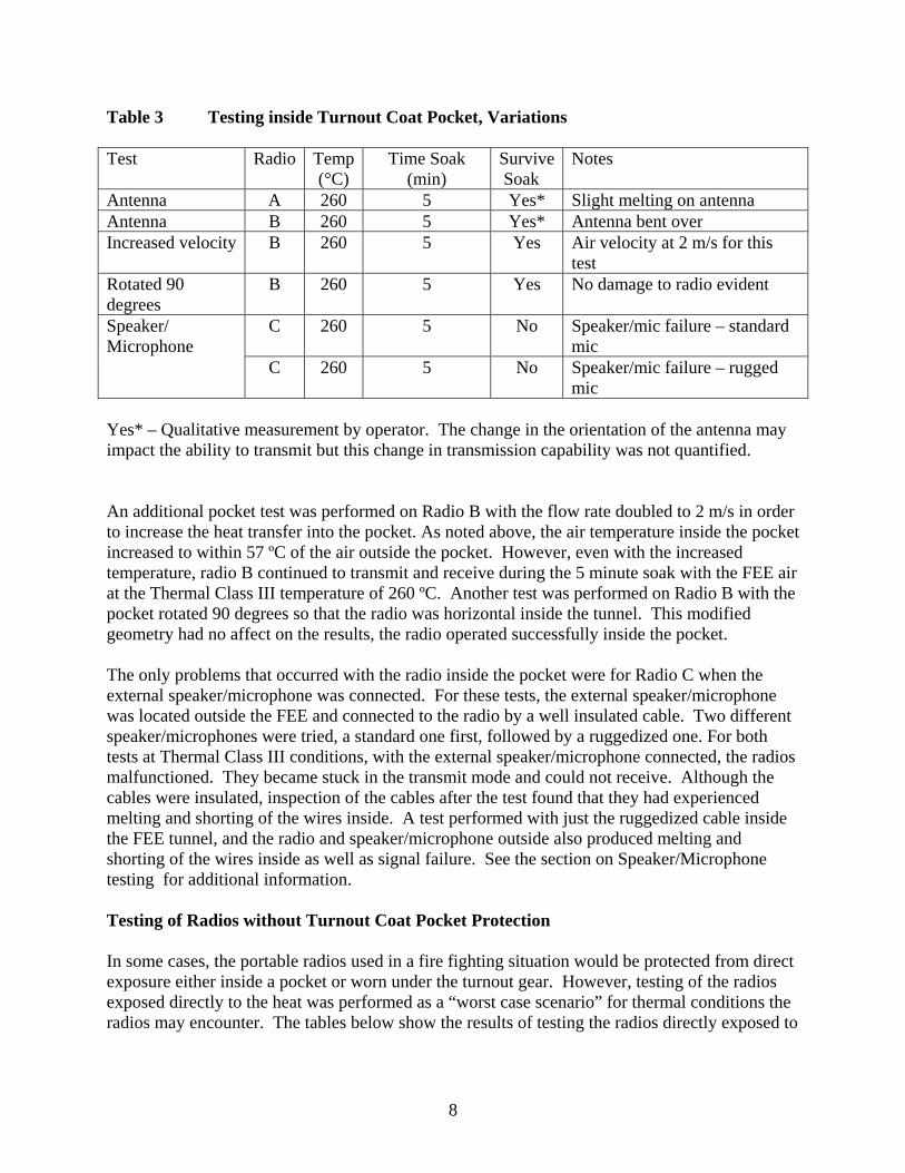
Table 3 Testing inside Turnout Coat Pocket, Variations Test Radio Temp
(°C) Time Soak
(min) Survive Soak
Notes
Antenna A 260 5 Yes* Slight melting on antenna Antenna B 260 5 Yes* Antenna bent over Increased velocity B 260 5 Yes Air velocity at 2 m/s for this
test Rotated 90 degrees
B 260 5 Yes No damage to radio evident
C 260 5 No Speaker/mic failure – standard mic
Speaker/ Microphone
C 260 5 No Speaker/mic failure – rugged mic
Yes* – Qualitative measurement by operator. The change in the orientation of the antenna may impact the ability to transmit but this change in transmission capability was not quantified. An additional pocket test was performed on Radio B with the flow rate doubled to 2 m/s in order to increase the heat transfer into the pocket. As noted above, the air temperature inside the pocket increased to within 57 ºC of the air outside the pocket. However, even with the increased temperature, radio B continued to transmit and receive during the 5 minute soak with the FEE air at the Thermal Class III temperature of 260 ºC. Another test was performed on Radio B with the pocket rotated 90 degrees so that the radio was horizontal inside the tunnel. This modified geometry had no affect on the results, the radio operated successfully inside the pocket. The only problems that occurred with the radio inside the pocket were for Radio C when the external speaker/microphone was connected. For these tests, the external speaker/microphone was located outside the FEE and connected to the radio by a well insulated cable. Two different speaker/microphones were tried, a standard one first, followed by a ruggedized one. For both tests at Thermal Class III conditions, with the external speaker/microphone connected, the radios malfunctioned. They became stuck in the transmit mode and could not receive. Although the cables were insulated, inspection of the cables after the test found that they had experienced melting and shorting of the wires inside. A test performed with just the ruggedized cable inside the FEE tunnel, and the radio and speaker/microphone outside also produced melting and shorting of the wires inside as well as signal failure. See the section on Speaker/Microphone testing for additional information. Testing of Radios without Turnout Coat Pocket Protection In some cases, the portable radios used in a fire fighting situation would be protected from direct exposure either inside a pocket or worn under the turnout gear. However, testing of the radios exposed directly to the heat was performed as a “worst case scenario” for thermal conditions the radios may encounter. The tables below show the results of testing the radios directly exposed to
9
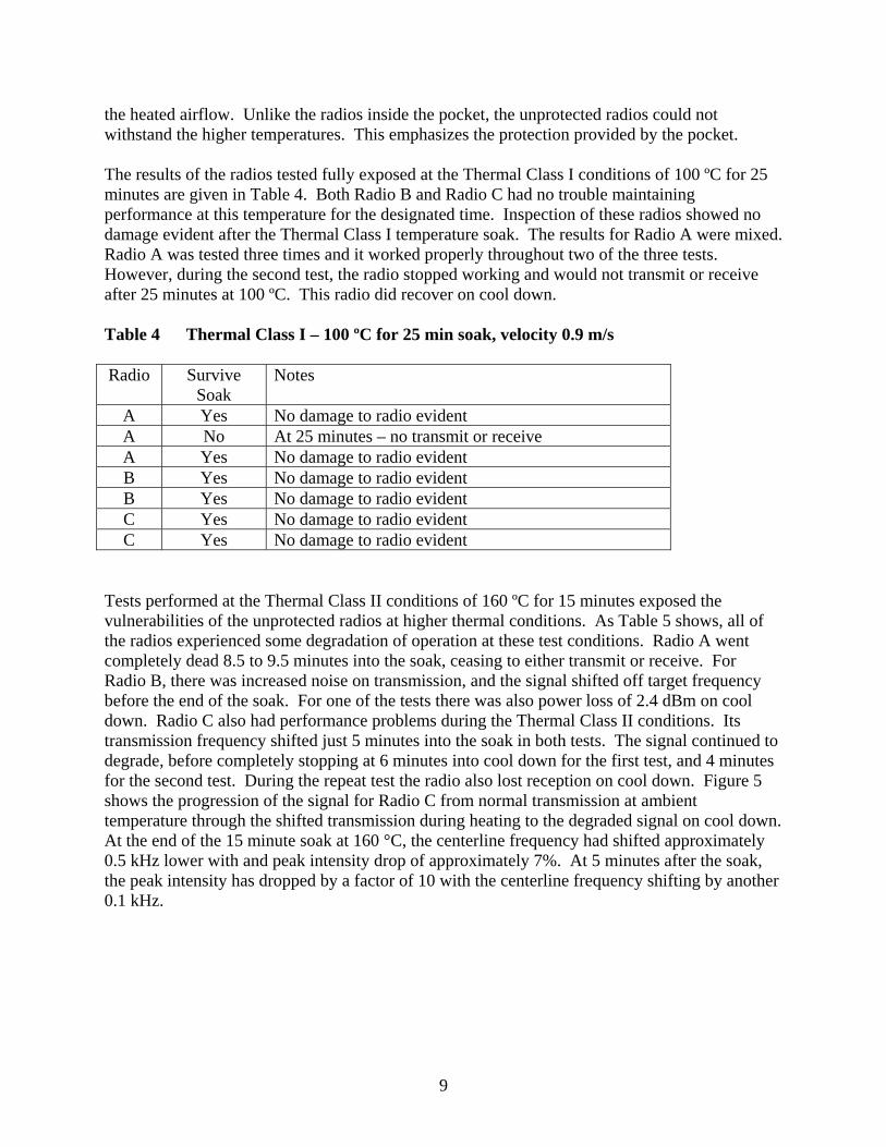
the heated airflow. Unlike the radios inside the pocket, the unprotected radios could not withstand the higher temperatures. This emphasizes the protection provided by the pocket. The results of the radios tested fully exposed at the Thermal Class I conditions of 100 ºC for 25 minutes are given in Table 4. Both Radio B and Radio C had no trouble maintaining performance at this temperature for the designated time. Inspection of these radios showed no damage evident after the Thermal Class I temperature soak. The results for Radio A were mixed. Radio A was tested three times and it worked properly throughout two of the three tests. However, during the second test, the radio stopped working and would not transmit or receive after 25 minutes at 100 ºC. This radio did recover on cool down. Table 4 Thermal Class I – 100 ºC for 25 min soak, velocity 0.9 m/s Radio Survive
Soak Notes
A Yes No damage to radio evident A No At 25 minutes – no transmit or receive A Yes No damage to radio evident B Yes No damage to radio evident B Yes No damage to radio evident C Yes No damage to radio evident C Yes No damage to radio evident
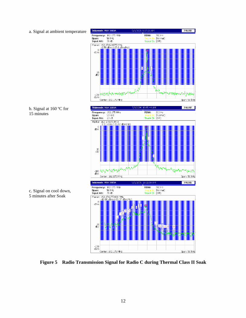
Tests performed at the Thermal Class II conditions of 160 ºC for 15 minutes exposed the vulnerabilities of the unprotected radios at higher thermal conditions. As Table 5 shows, all of the radios experienced some degradation of operation at these test conditions. Radio A went completely dead 8.5 to 9.5 minutes into the soak, ceasing to either transmit or receive. For Radio B, there was increased noise on transmission, and the signal shifted off target frequency before the end of the soak. For one of the tests there was also power loss of 2.4 dBm on cool down. Radio C also had performance problems during the Thermal Class II conditions. Its transmission frequency shifted just 5 minutes into the soak in both tests. The signal continued to degrade, before completely stopping at 6 minutes into cool down for the first test, and 4 minutes for the second test. During the repeat test the radio also lost reception on cool down. Figure 5 shows the progression of the signal for Radio C from normal transmission at ambient temperature through the shifted transmission during heating to the degraded signal on cool down. At the end of the 15 minute soak at 160 °C, the centerline frequency had shifted approximately 0.5 kHz lower with and peak intensity drop of approximately 7%. At 5 minutes after the soak, the peak intensity has dropped by a factor of 10 with the centerline frequency shifting by another 0.1 kHz.

10
Table 5 Thermal Class II – 160 ºC for 15 min soak, velocity 0.9 m/s Radio Survive
Soak Notes
A No 9 ½ min – no transmit or receive A No 8 ½ min – no transmit or receive B No Transmission signal shift, increased noise B No Transmission signal shift, power loss and increased noise C No Transmission signal shift, no transmission on cool down C No Transmission signal shift, no transmit or receive on cool down
Because none of the radios survived at the Thermal Class II conditions, testing did not immediately progress to Thermal Class III conditions. The radios were tested at high temperatures for the relatively short 5 minute time period, but were subjected to temperatures lower than the Thermal Class III temperature of 260 ºC, with the air velocity remaining at nominally 0.9 m/s. Because Radio C had shown transmission signal irregularity after only 5 minutes at the Thermal Class II temperature of 160 ºC, it was not tested at a higher temperature. Table 6 shows the results for the 5 minutes soaks at temperatures beyond 160 ºC. The transmission signal for Radio A did not maintain frequency when the temperature was at 190 ºC and 200 ºC. Radio B was able to transmit and receive for 5 minutes at the temperature of 220 ºC; however there was some melting of the radio casing, especially around the speaker, the display area and the top switches. When radio B was tested at 230 ºC, the radio reception was not successful during either trial. Table 6 Temperatures beyond 160 ºC, for 5 min soak velocity 0.9 m /s Radio Temp
(ºC) Time Soak
(min) Survive Soak Notes
A 190 5 No transmission signal shift, melting of casingA 200 5 No Reception quality and volume degrades,
transmission signal shift B 220 5 Yes Some melting of casing B 230 5 No Reception loss at 150s into soak (analog) B 230 5 No Reception loss at 150s into soak (digital)
Speaker/Microphone testing The results of the speaker/microphone testing are summarized in Table 7. The flow velocity was set at nominally 0.9 m/s for all tests. In general, the speaker/microphones for all radios remained fully functional and did not have any damage during the tests at Thermal Class I and Class II conditions. The only problem occurred for Radio C, where during a Thermal Class I test, the reception volume of the speaker decreased. For two subsequent tests at this Thermal Class I condition, the speaker/microphone operated normally without any decrease in volume. None of the speaker/microphones were able to operate normally during the soak at the Thermal Class III
11
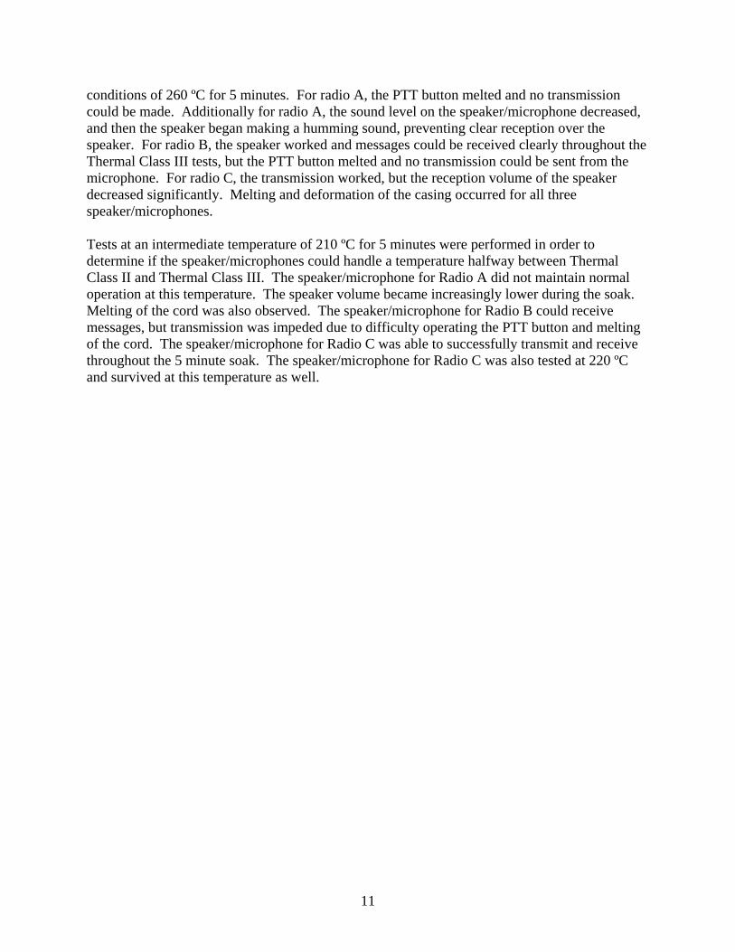
conditions of 260 ºC for 5 minutes. For radio A, the PTT button melted and no transmission could be made. Additionally for radio A, the sound level on the speaker/microphone decreased, and then the speaker began making a humming sound, preventing clear reception over the speaker. For radio B, the speaker worked and messages could be received clearly throughout the Thermal Class III tests, but the PTT button melted and no transmission could be sent from the microphone. For radio C, the transmission worked, but the reception volume of the speaker decreased significantly. Melting and deformation of the casing occurred for all three speaker/microphones. Tests at an intermediate temperature of 210 ºC for 5 minutes were performed in order to determine if the speaker/microphones could handle a temperature halfway between Thermal Class II and Thermal Class III. The speaker/microphone for Radio A did not maintain normal operation at this temperature. The speaker volume became increasingly lower during the soak. Melting of the cord was also observed. The speaker/microphone for Radio B could receive messages, but transmission was impeded due to difficulty operating the PTT button and melting of the cord. The speaker/microphone for Radio C was able to successfully transmit and receive throughout the 5 minute soak. The speaker/microphone for Radio C was also tested at 220 ºC and survived at this temperature as well.
12
a. Signal at ambient temperature b. Signal at 160 ºC for 15 minutes c. Signal on cool down, 5 minutes after Soak
Figure 5 Radio Transmission Signal for Radio C during Thermal Class II Soak

13
Table 7 External Speaker/Microphone Testing, velocity 0.9 m/s
Radio Temp (ºC)
Time Soak (min)
Survive Soak
Notes
A 100 25 Yes No damage A 160 15 Yes No damage A 210 5 No Reception volume decreased, cord and case melted A 260 5 No No transmit or receive, Push to talk button (PTT)
melted-does not work, cord melted, case deformed B 100 25 Yes No damage B 160 15 Yes No damage B 210 5 No PTT difficult to press, cord melted B 260 5 No No transmission, PTT melted, cord melted C 100 25 No Reception volume decreased C 100 25 Yes No damage C 100 25 Yes No damage C 160 15 Yes No damage C 160 15 Yes No damage C 210 5 Yes No damage C 220 5 Yes No damage C 260 5 No Volume decreased, some melting and deformation
DISCUSSION The results of these tests exposed the vulnerability of the portable radios to elevated temperature conditions, and emphasized the need to protect the radios when used in firefighting situations. Radios tested inside the turnout gear pocket showed that the turnout gear pocket was able to protect the radios and allow them to operate at the Thermal Class III temperature of 260 ºC. This contrasts with tests where the radios were exposed directly to the airflow, in which the radios did not survive at Thermal Class II conditions and beyond. In all but one test, the exposed radios were able to operate properly at the Thermal Class I temperature of 100 ºC, above the listed maximum operating temperature of 60 ºC. Failure of the electronics due to heating was not permanent for the radios. In all cases where the radio casing was not damaged, the radios regained normal operating function once they had sufficiently cooled. Permanent damage to the casing, such as difficulty turning knobs or pressing buttons did occur for some radios whose casings experienced melting. Permanent damage also occurred to the external speaker/microphones, especially due to the melting of the connecting cables. The radio transmission signal was measured using the signal analyzer. Each radio was programmed to Very High Frequency (VHF) frequency 162.175 MHz assigned for testing purposes. Baseline transmissions were recorded with the radio at ambient room temperatures. When the radio was heated, a deviation of the transmission signal from the programmed

14
frequency of greater than 0.1 kHz signaled the start of degradation of the transmission signal, and indicated that further problems were imminent. It should be noted that in most tests when the radio was heated above 160 ºC the liquid crystal display (LCD) display became darkened and in some cases it became unreadable. The impaired display was not considered a communication malfunction because the display was not needed for radio communication; it was used for radio programming and other setup functions that would not be used in the emergency situation. Not all of the radios had an LCD displays. Testing of the external speaker/microphones fully exposed to the heated airflows showed that these parts were better able to perform at the elevated temperatures than the radios themselves. While none of the speaker/microphones survived the Thermal Class III conditions of 260 ºC for 5 minutes, they were able to operate during most of the tests at lower temperatures. Since this is the part of the radio system most likely to be directly exposed to harsh environments, it is crucial for this part to be able to withstand thermal stress without protection. Connecting the external speaker/microphones required that the connector cord be screwed into place on the side of the radio. Some of the radios operated such that when the external speaker/microphone was connected, it disabled the PTT and speaker on the radio itself, diverting all transmission and reception to the external speaker/microphone. If the external speaker/microphone or its cord were to fail, in an emergency situation it would be extremely difficult (if not impossible) to disconnect the speaker/microphone and operate the radio by itself. Thus failure of the external speaker/microphone, the part most likely to be exposed to extreme conditions, could mean loss of the radio operation entirely. CONCLUSION The performance of handheld radios in thermal environments encountered by firefighters based on the experimental data in this paper suggests the following recommendations.
1. Handheld radios without additional thermal protection should be treated as Thermal Class I electronics.
2. Radios protected in turnout gear pockets may be treated as Thermal Class II electronics. 3. Standards for the thermal protection afforded by turnout gear pockets need to be
developed to support recommendation 2. 4. While pocket protected radios withstood Thermal Class III conditions, the cord and
speaker/microphone limited their performance to Thermal Class II conditions. Improving the thermal performance of the speaker/microphone and cord could move pocket protected radios to Thermal Class III electronics.
Since firefighter turnout gear is designed to protect firefighters exposed to Thermal Class III conditions, handheld radios should be constructed to handle these conditions. One of the radios tested, Radio C, had a speaker/microphone and cord that almost survived Thermal Class III conditions which suggests that small design changes may be all that are necessary to reach the Thermal Class III rating.

15
The next step for this project is to work with the NFPA to develop a radio standard that would include requirements for the thermal testing of handheld radios.
16
REFERENCES 1. Donnelly M. K., Davis W. D., Lawson, J. R., and Selepak, M. S., “Thermal Environment for
Electronic Equipment used by First Responders,” National Institute of Standards and Technology, Gaithersburg, MD, NIST Technical Note 1474; January 2006.
2. National Fire Protection Association, NFPA 1221 Standard on Installation, Maintenance and Use of Emergency Services Communications Systems, 2002 Edition, Volume 11. National Fire Protection Association, 1 Batterymarch Park, P.O. Box 9101, Quincy, MA 02269-9101.

17
ACKNOWLEDGEMENT This work was sponsored by the Department of Homeland Security (DHS) via the NIST Office of Law Enforcement Standards (OLES) to advance the development of Standards for Electronic Equipment used by Emergency Responders.