Testing of plasma facing materials and components · high cycle thermal fatigue monoblock CFC Wall...
66
Mitglied der Helmholtz-Gemeinschaft Association EURATOM – FZJ 13th PFMC Workshop / 1st FEMaS Conference, Tutorial Course, Rosenheim, 09. – 13.05.2011 J. Linke Forschungszentrum Jülich, Euratom Association, 52425 Jülich, Germany Testing of plasma facing materials and components
Transcript of Testing of plasma facing materials and components · high cycle thermal fatigue monoblock CFC Wall...

Mitglie
d d
er
Helm
holtz-G
em
ein
schaft
Association EURATOM – FZJ
13th PFMC Workshop / 1st FEMaS Conference, Tutorial Course, Rosenheim, 09. – 13.05.2011
J. Linke
Forschungszentrum Jülich, Euratom Association, 52425 Jülich, Germany
Testing of plasma facing materials and
components

Mit
glie
d d
er
Helm
ho
ltz-G
em
ein
sc
haft
Association EURATOM – FZJ
A Plasma wall interaction – thermal loads
B High heat flux test facilities
D Intense transient loads
E Neutron induced material degradation
C Cyclic quasi-stationary loads
Outline:
13th PFMC Workshop / 1st FEMaS Conference, Tutorial Course, Rosenheim, 09. – 13.05.2011

Plasma facing components in TEXTOR
• FW, limiters or divertor: individual tiles
• no actively cooling of wall components
• no tritium operation no neutron damage
• no need for remote controlled installation

Plasma facing components in ITER
• FW-modules, divertor cassettes
• actively cooled plasma facing components
• tritium operation neutrons activation
• remote controlled installation and
replacement of components

A Plasma wall interaction – thermal loads
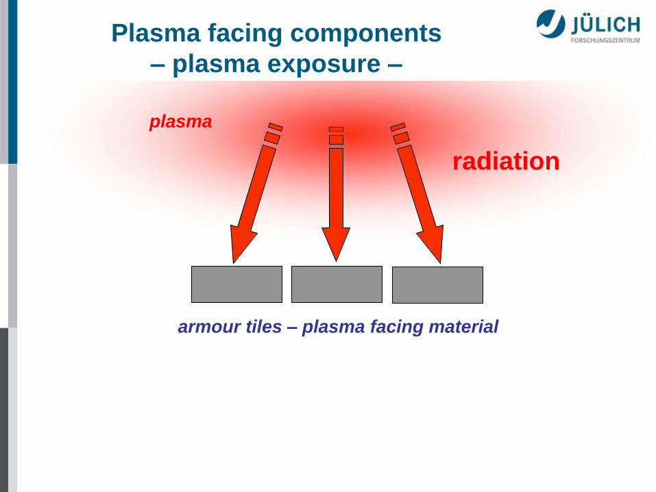
radiation
armour tiles – plasma facing material
plasma
Plasma facing components
– plasma exposure –
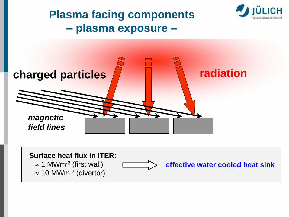
radiation charged particles
magnetic
field lines
Surface heat flux in ITER:
1 MWm-2 (first wall)
10 MWm-2 (divertor) effective water cooled heat sink
Plasma facing components
– plasma exposure –

water cooled heat sink (ITER)
helium and/or liquid metal cooled (beyond ITER)
Plasma facing components
– plasma exposure –
charged particles
approx. 105 joints in the ITER divertor
acceptable failure rate = 0
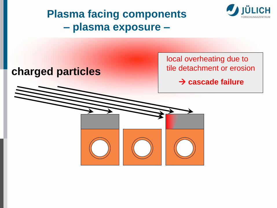
charged particles cascade failure
local overheating due to
tile detachment or erosion
Plasma facing components
– plasma exposure –

Plasma facing components
– design options –
charged particles safety against tile losses:
monoblock design

charged particles
defect in the braze joint
Plasma facing components
– design options –

charged particles
Plasma facing components
– design options –

hypervapotron flat tile design monoblock
Plasma facing material: • beryllium (first wall)
• CFC, tungsten (divertor)
Heat sink material: • copper alloys (CuCrZr, DS-Cu)
• stainless steel (first wall)
Joining techniques: • brazing
• HIPing
• e-beam welding
• diffusion bonding
Plasma facing components
– design options –

source: M. Merola, ISFNT-9, Dalian, China, 2009 &
http://www.iter.org/doc/www/newsline/Newsline/116/blanket.jpg
Plasma facing components
for ITER
440 first wall panels
(1.5 m)
54 divertor cassettes
(3.4 m)
beryllium tungsten
CFC
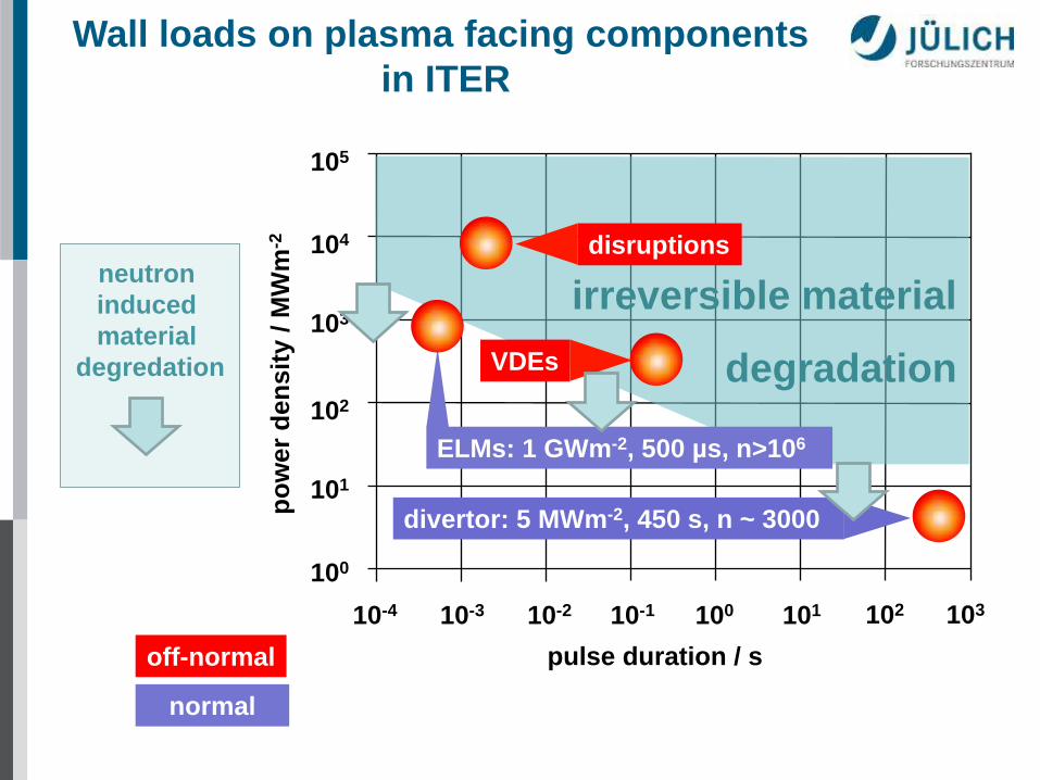
irreversible material
degradation
100 10-4 10-3 103 102 101 10-2 10-1
pulse duration / s
105
104
103
102
101
100
po
wer
den
sit
y / M
Wm
-2
off-normal
disruptions
VDEs
ELMs: 1 GWm-2, 500 µs, n>106
normal
divertor: 5 MWm-2, 450 s, n ~ 3000
neutron
induced
material
degredation
Wall loads on plasma facing components
in ITER

High heat flux components in non-fusion applications
Power density MW/m2
1
reentry vehicle
Rolls-Royce Trent 900
85
Ariane 5 / Vulcain 2
20
ITER Divertor
2000
ELMs in ITER
PWR-fuel element
Vulcain 2 10 minutes burn time

Normal operation regime:
5 – 10 MWm-2, t = 450 s
low cycle thermal fatigue
critical area
flat tile design monoblock
Wall loads on plasma facing components
in ITER

critical area
flat tile design
W
Thermal load during ELMS:
1 GWm-2, t = 500 µs, 1 Hz
high cycle thermal fatigue
monoblock
CFC
Wall loads on plasma facing components
in ITER
High Heat Flux test facilities
B

Electron beam simulation of ITER relevant
thermal loads
1 electron beam gun
2 vacuum chamber
3 cooling circuit
4 test component
5. diagnostics
Electron beam test facility JUDITH 2
P = 200 kW (30...60 keV)
P/a 10 GWm-2
e-beam
0
10
20
0 10 20 30 40 50 60 70
y / mm
x / mm
fatigue testing: up to 20 MWm-2
10 s on / 10 s off
typical beam mode for
thermal fatigue test

High heat flux test facilities (simulation of quasi-stationary heat loads – thermal fatigue)
facility particle
type
particle
energy
[keV]
beam
power
[kW]
max. loaded
area
[m2]
power
density
[GWm-2]
remarks institute
ITER-
partner
A
TSEFEY e- 30 60 0.25 0.2 scanned beam, = 20 mm
beryllium compatible
Efremov
RF
Tsefey-M
Since 2008)
e- 40 200 1.0 1.0 scanned beam, = 8÷20 mm
beryllium compatible
hot water- & hot He cooling loop
Efremov
RF
IDTF (ITER
Divertor Test
Facility)
e- 60 800 2.25 1.0 scanned beam, = 15÷50 mm
hot (ITER-like) water cooling loop
Efremov
RF
B JUDITH1
JUDITH2 e- 120
30 - 60
60
200
0.01
0.25 10
irradiated samples
beryllium
FZJ
EU
C FE 200 e-
200 200 1.0 60 scanned beam, 2 - 3 mm
hot coolant loop
CEA
EU
D JEBIS e-
100 400 0.18 2 beam sweeping
1 - 2 mm
JAEA
JA
E EB 1200 e-
40 1200 0.27 10 scanned beam, 2 - 12 mm
hot coolant loop
SNLA
US
F DATS H+, He+ 50 1500 0.1 0.06 2 ion sources à 0.75 MW
150 mm
JAEA
JA
G GLADIS H+ 50 2200 0.3 0.05 2 ion sources à 1.1 MW
70 mm
IPP
EU
H MARION H+, He+
60 5000 0.01 0.12 1 ion source à 5 MW
200 mm
FZJ
EU
Other HHF test facilities: IR test stands (≤ 1MW/m2), solar furnaces
plasma wind tunnel (reenty vehicles), burner rigs (TBCs)

ion beam facilities for the simulation of
quasi-stationary heat loads
DATS MARION
GLADIS
High heat
flux test facilities

0
200
400
600
800
1000
1200
1400
1600
0 2 4 6 8 10
15.5
12.8
10.2
7.3
5.1
2.5
1.0
power density
(MW/m2)
High heat flux experiment
– screening test –
time (s)
tem
pera
ture
(°C
)

Thermal response of different
CFC-modules
0
500
1000
1500
2000
2500
0 5 10 15 20 25 30
power density / MWm-2
surf
ace tem
pera
ture
/ °
C
Dunlop Conc.1 / CuCrZr
Dunlop Conc.1 / DS-Cu
Sepcarb N31 / DS-Cu
12 mm CFC
6 mm CFC

CFC flat tile
CFC monoblock
W macrobrush
W monoblock
CFC armour fl
at
tile
desig
n
mo
no
blo
ck d
esig
n
1000 cycles @ 19 MWm-2
1000 cycles @ 25 MWm-2
1000 cycles @ 18 MWm-2
1000 cycles @ 20 MWm-2
tungsten armour
Silicon doped CFC NS31, active metal
casting, e-beam welding to CuCrZr heat sink coating of WLa2O3 tiles with OFHC-Cu,
e-beam welding to CuCrZr heat sink
drilling of CFC tiles (NB31), active metal
casting (AMC®) low temperature HIPing lamellae technique, drilling of WLa2O3
blocks, casting with OFHC-Cu, HIPing
Fatigue testing on PFCs for ITER

transient thermal loads:
plasma disruptions, VDEs & ELMs
D

Solar flares, a stellar equivalent to ELMs
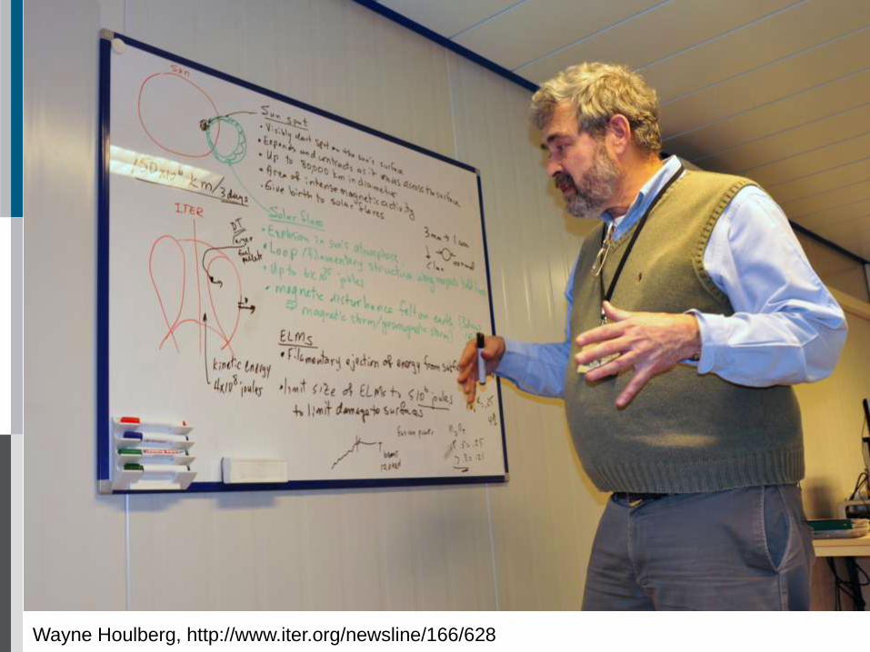
Wayne Houlberg, http://www.iter.org/newsline/166/628

ELM simulation
– main influencing parameters –

Diagnostic
windows
Vacuum
chamber
(receiver)
600
QSPA plasma parameters (ELMs):
• Heat load 0.5 – 2 MJ/m2
• Pulse duration 0.1 – 0.6 ms
• Plasma diameter 5 cm
• Magnetic field 0 T
• Ion impact energy ≤ 0.1 keV
• Electron temperature < 10 eV
• Plasma density ≤ 1022 m-3
Quasi Stationary Plasma Accelerator (QSPA)
The energy density distribution on W surface,%
Simulation of short transient heat pulses
Source: A. Zhitlukhin, 17th PSI, Hefei, 2006

Simulation of ELMs in QSPA

W 3
plasma stream
Simulation of ELMs in QSPA
t = 500 µs 100 pulses E = 0.5 MJm-2 T0 = 500°C


t = 500 µs 100 pulses E = 1.0 MJm-2
Simulation of ELMs in QSPA
T0 = 500°C
W 3
plasma stream
W 3
tungsten
target

W3
melt motion
melt motion starts at
‘vertical cracks‘
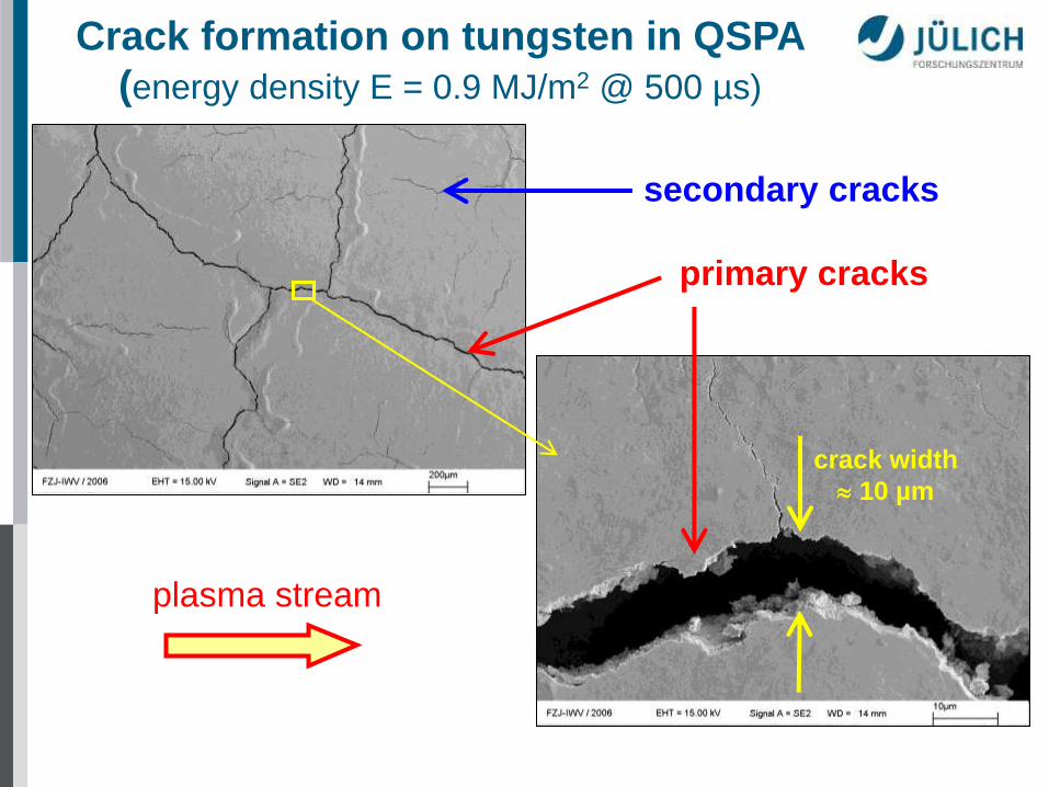
Crack formation on tungsten in QSPA
(energy density E = 0.9 MJ/m2 @ 500 µs)
plasma stream
crack width
10 µm
primary cracks
secondary cracks

W 3
0.9 MJ.m-2
plasma stream
500 m 500 µm 500 µm
500 µm 500 µm 500 µm
Crack formation on tungsten in QSPA

secondary cracks: depth 50 µm
primary cracks: depth 500 µm
Crack formation at the melting threshold
E 1.0 MJm-2, t = 500 µs, n = 100

Bridging of gaps due to melt motion 100 shots @ E = 1.6 MJ/m2
Source: A. Zhitlukhin et al., SRC RF TRINITI, Troitsk

Bridge formation between tungsten tiles
Plasma stream
direction
1mm
W4,L3, 10 exposures
1mm
W4,L3, 20 exposures
1mm
W4,L3, 50 exposures
w =
1.6
MJ/m
2
W3,R3, 20 exposures
1mm
W3,R3, 50 exposures
1mm
W3,R3, 100 exposures
1mm
w =
1.0
MJ/m
2
Source: A. Zhitlukhin et al., SRC RF TRINITI, Troitsk

Transient heat load tests on tungsten
0.63 GW/m² at RT
0.63 GW/m² at 400°C 0.16 GW/m² at 400°C
W-UHP
Electron beam simulation of ELM-specific thermal loads (n = 100)

W-UHP
100 cycles with a duration of 1 ms; absorption coefficient: 0.46
damage
threshold
cra
ck
ing
th
res
ho
ld
Transient heat load tests on tungsten
Electron beam simulation of ELM-specific thermal loads (n = 100)
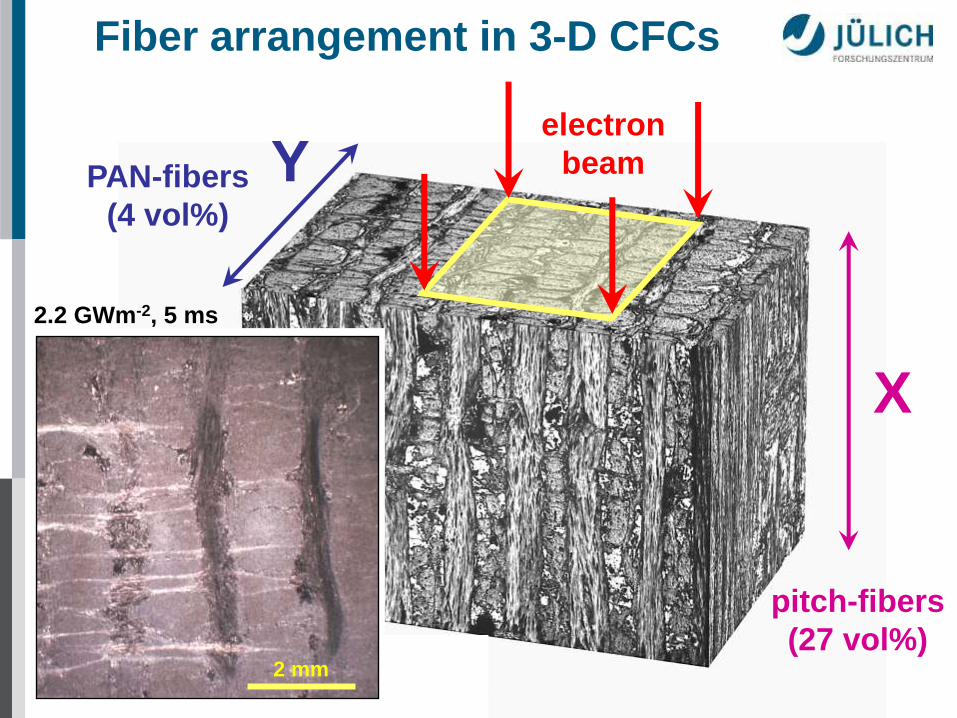
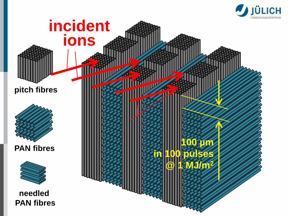
Fiber arrangement in 3-D CFCs
PAN-fibers
(4 vol%)
pitch-fibers
(27 vol%)
Needled PAN-fibers (4 vol%)
Z
Y
X
electron
beam
2 mm
2.2 GWm-2, 5 ms

X: pitch fibres
Y: PAN fibres
Z: needled
PAN fibres
Fibre assembly in a 3D-CFC (NB31)
Y
X
Z

pitch fibres
PAN fibres
needled
PAN fibres
electron beam

pitch fibres
PAN fibres
needled
PAN fibres
Fibre assembly in a 3D-CFC (NB31)

pitch fibres
PAN fibres
needled
PAN fibres
Fibre assembly in a 3D-CFC (NB31)

pitch fibres
PAN fibres
needled
PAN fibres
Fibre assembly in a 3D-CFC (NB31)
pitch fibres
PAN fibres
needled
PAN fibres
incident ions
100 µm
in 100 pulses
@ 1 MJ/m2

Thermally induced erosion of NB31
pitch fibers pitch fibers PAN fibers needled PAN fibers
100 µm
E 1.0 MJm-2, t = 500 µs, n = 100 erosion depth: 1 µm / shot
ELM simulation experiments in QSPA, TRINITI, RF

pitch fibers needled PAN fibers
PAN fibers pitch fibers
erosion depth: 1 µm / shot
modeling: S. Pestchanyi et al., KIT
Thermally induced erosion of NB31

modeling: S. Pestchanyi et al., KIT
PAN fibers pitch fibers
modeling: B. Bazylev et al., KIT
Thermally induced erosion of NB31

50 µm
Crack formation in pitch fibers of NB31
E 0.7 MJm-2, t = 500 µs, n = 100
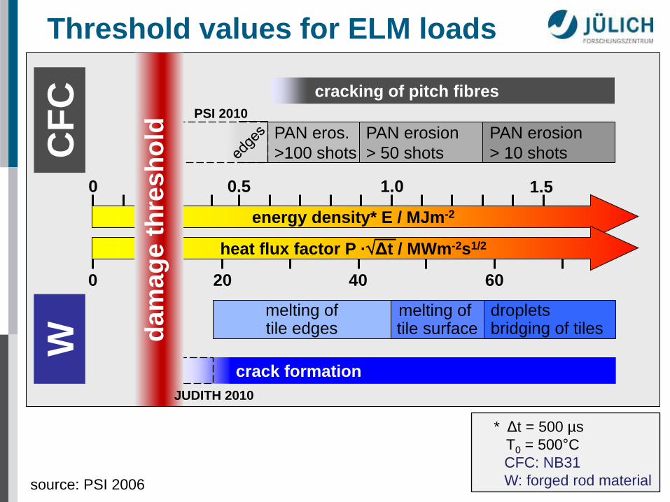
CF
C
W
energy density* E / MJm-2
0.5 1.0 1.5 0
heat flux factor P ·Δt / MWm-2s1/2
20 40 0 60
melting of tile surface
droplets bridging of tiles
melting of tile edges
crack formation
cracking of pitch fibres
PAN eros.
>100 shots
PAN erosion
> 50 shots
PAN erosion
> 10 shots
* Δt = 500 µs
T0 = 500°C
CFC: NB31
W: forged rod material
Threshold values for ELM loads
da
ma
ge
th
res
ho
ld
source: PSI 2006
PSI 2010
JUDITH 2010
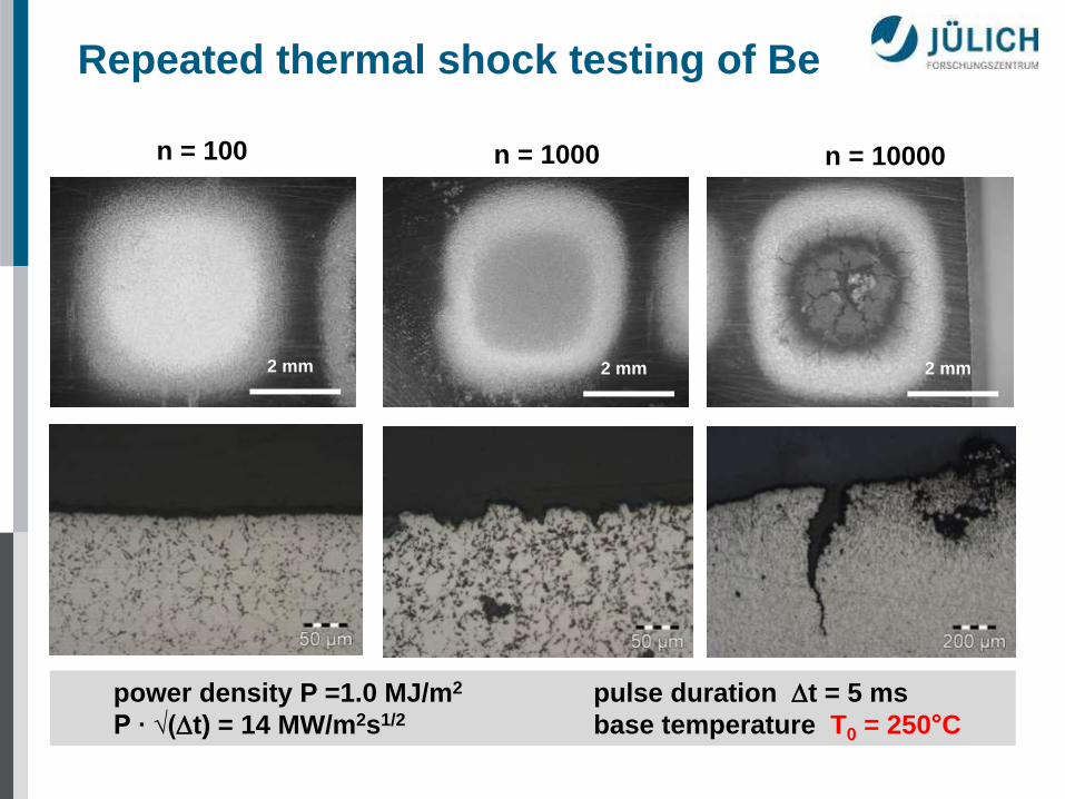
Repeated thermal shock testing of Be
power density P =1.0 MJ/m2 pulse duration t = 5 ms
P ∙ √(t) = 14 MW/m2s1/2 base temperature T0 = 250°C
2 mm
n = 100 n = 1000
2 mm
n = 10000
2 mm

ELM simulation tests on tungsten
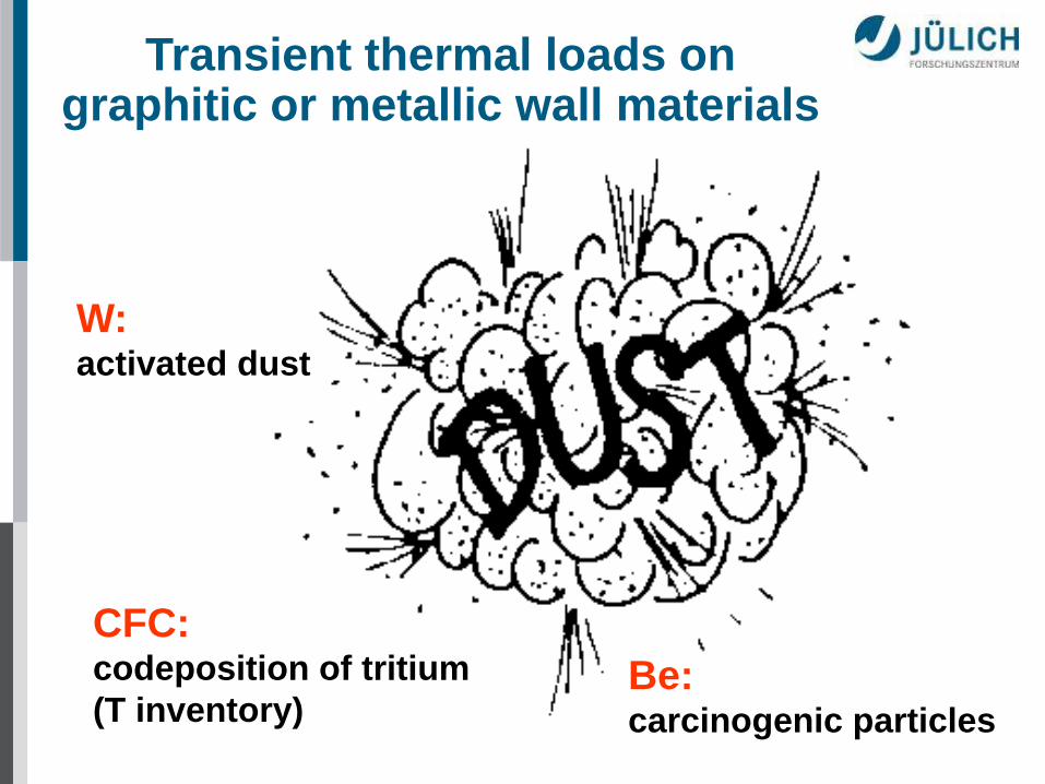
Transient thermal loads on graphitic or metallic wall materials
... are there any safety issues?
CFC: codeposition of tritium
(T inventory) Be: carcinogenic particles
W: activated dust

neutron induced material degradation
(fn = 1025 n/m2 1 dpa for ITER)
E

Neutron-induced material degradation
High Flux Reactor (HFR)
Petten, The Netherlands
Neutron induced effects: • activation of plasma facing
and structural materials
e.g. Co, Ag
• transmutation due to 14 MeV
neutrons
W Re Os
Ag Cd
Be He, T
• degradation of thermal and
mechanical properties
thermal conductivity,
hardening,
embrittlement

Neutron irradiation in
materials test reactors
Tirr [°C]
fluence [dpa]
irradiated materials completion
#1 350 0.35 02/96
#2 700 0.35
Be, CFCs, W-alloys SiC 02/96
#3 200 0.2 12/99
#4 200 1.0
CFCs, W-alloys, Cu-alloys, joints 10/99
thermal shock specimens
4-point bending test
mechanical testing of joints
thermal conductivity
actively cooled divertor
modules
(all dpa‘s in carbon)
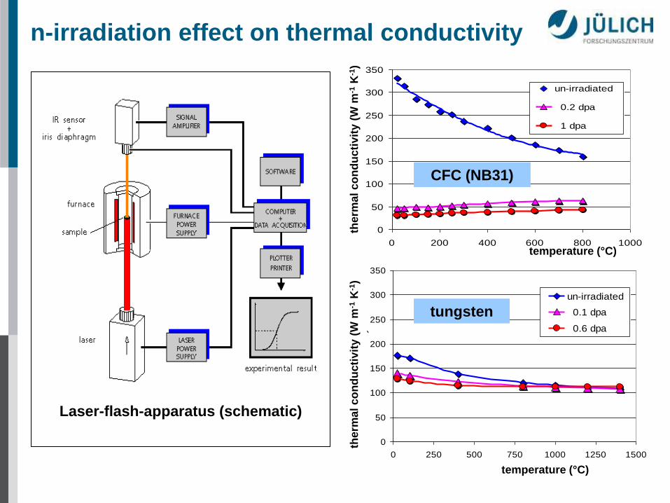
n-irradiation effect on thermal conductivity
therm
al co
nd
ucti
vit
y (
W m
-1 K
-1)
temperature (°C)
0
50
100
150
200
250
300
350
0 250 500 750 1000 1250 1500
temperature / °C
the
rma
l co
nd
uctiv
ity / W
/mK
un-irradiated
0.1 dpa
0.6 dpa
0
50
100
150
200
250
300
350
0 200 400 600 800 1000
temperature /°C
th. c
ondu
ctiv
ity /
W/m
K
un-irradiated
0.2 dpa
1 dpa
Polynomisch
(un-irradiated)
therm
al co
nd
ucti
vit
y (
W m
-1 K
-1)
temperature (°C)
CFC (NB31)
tungsten
Laser-flash-apparatus (schematic)
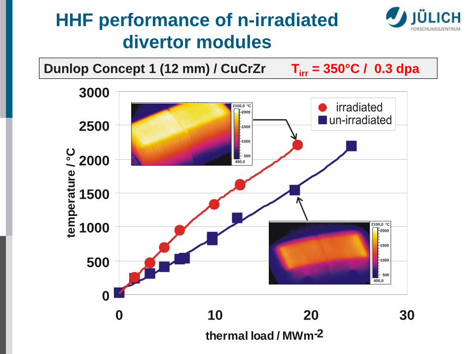
Dunlop Concept 1 (12 mm) / CuCrZr
HHF performance of n-irradiated
divertor modules
0
5 0 0
1 0 0 0
1 5 0 0
2 0 0 0
2 5 0 0
3 0 0 0
0 1 0 2 0 3 0
t h e r m a l l o a d / M W m - 2
t e m
p e r
a t u r e
/ ° C
IR - DZ150SS.IMD
Zykliertests an CFC-Modulen vom Type N07.08.96
400,0
2100,0 °C
500
1000
1500
2000
IR - 551_11~1.IMG
25:09:97 09:59:34
400,0
2100,0 °C
500
1000
1500
2000 b e s t r a h l t u n b e s t r a h l t
Dunlop Concept 1 (12 mm) / CuCrZr Tirr = 350°C / 0.3 dpa

CFC flat tile
CFC monoblock
W macrobrush
W monoblock
CFC armour fl
at
tile
desig
n
mo
no
blo
ck d
esig
n
0 dpa: 1000 cycles @ 19 MWm-2 1 dpa: 1000 cycles @ 15 MWm-2
(no degradation)
0 dpa: 1000 cycles @ 25 MWm-2 1 dpa: 1000 cycles @ 12 MWm-2
(substancial evaporation @ 14 MWm-2)
0 dpa: 1000 cycles @ 18 MWm-2 0.6 dpa: 1000 cycles @ 10 MWm-2
(increasing of Tsurf)
0 dpa: 1000 cycles @ 20 MWm-2 0.6 dpa: 1000 cycles @ 18 MWm-2
(no degradation)
tungsten armour
Fatigue testing on PFCs for ITER

Characterization of plasma facing
materials
Microstructure / composition • metallography / ceramography • optical microscopy • electron microscopy (SEM, TEM ….) • analytical tools (EDX, Auger, SIMS, RBS …)
Mechanical properties • strength (tensile, compressive) • Young‘s modulus • fracture toughness
Thermal properties • thermal diffussivity (conductivity) • thermal expansion coefficient (CTE) • specific heat • emissivity
Electrical and optical properties
Corrosion / erosion behaviour
Neutron irradiation performance
Thermal shock resistance under transient loads
ITER Materials Documents Materials Properties Handbook
Materials Assessment Report
and many other data bases

Summary
Materials characterization
• an extensive data base is required including microstructure and all
physical properties (mechanical, thermal, electrical, optical etc.)
• these parameters are required for monolithic materials, coatings and
interlayers for a wide temperature range & different material treatment
• dust formation is a serious safety issue
(codeposition of tritium, toxic Be dust, activated tungsten particles)
Thermal fatigue and thermal shock
• off-normal events such as VDEs or disruptions result cause damage
(melting, crack formation, ...) – effect of ELMs needs further analyses
• technical solutions for cyclic thermal loads up to ~20 MWm-2 are available
(CFC- or W-monoblocks represent a very robust design solution)
• the surface temperature of carbon based high heat flux components is
significantly increased after neutron irradiation
Material degradation by energetic neutrons
• the thermal conductivity is decreased significantly (e.g. graphite / CFC)