Testing of methods for the determination of Young's ... ·...
76
Transcript of Testing of methods for the determination of Young's ... ·...


TESTING OF METHODS FOR THE DETERMINATION
OF YOUNG'S MODULUS BY BENDING
BY
ALBERT WASHINGTON MARKER
Ph.B. Northwestern College, 1907
THESIS
Submitted in Partial Fulfillment of the Requirements for the
Degree of
MASTER OF ARTS
IN PHYSICS
IN
THE GRADUATE SCHOOL
OF THE
UNIVERSITY OF ILLINOIS
1916


UNIVERSITY OF ILLINOISTHE GRADUATE SCHOOL
Au^us.t.....9. 1916
I HEREBY RECOMMEND THAT THE THESIS PREPARED UNDER MY SUPER-
VISION BY ALBERT......WASEI.NG.T.0.K....11ARKER..
ENTITLED .T.ES.T.LNG D.E....lIETHO.jDS.....EQE.....THE DETERMIMXION OF.
Y.QU1I.G..'..S. MQnULUS.....BX....EEJiDIJ.a.,
BE ACCEPTED AS FULFILLING THIS PART OF THE REQUIREMENTS FOR THE
DEGREE OF MASTES.....OZ....ARTa....Iil..PHI..SI.QS
' Head of Department
Recommendation concurred in ;*
Committee
on
Final Examination*
^Required for doctor's degree but not for master's.


TABLE OF CONTENTS
Page
I Introduction 1
II Historical 1
III Apparatus. , , 7
IV Methods 7
V Data 24
VI Sources of Error 29
VII Conclusions. 30

Digitized by the Internet Archive
in 2013
'JtUC
http//archive.org/details/testingofmethodsOOmark
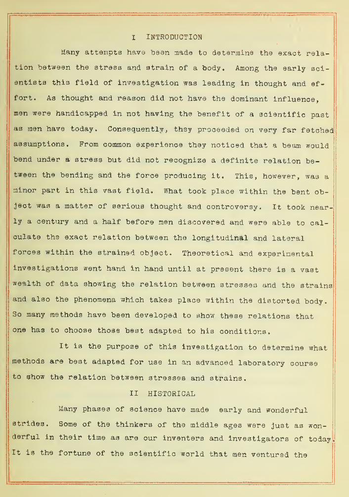
I INTRODUCTION
Many attempts have bean made to determine the exact rela-
tion between the stress and strain of a body. Among the early sci-
entists this field of investigation was leading in thought and ef-
fort. As thought and reason did not have the dominant influence,
men were handicapped in not having the benefit of a scientific past
as men have today. Consequently, they proceeded on very far fetched
assumptions. From common experience they noticed that a beam would
bend under a stress but did not recognize a definite relation be-
tween the bending and the force producing it. This, however, was a
minor part in this vast field. What took place within the bent ob-
ject was a matter of serious thought and controversy. It took near-
ly a century and a half before men discovered and were able to cal-
culate the exact relation between the longitudinal and lateral
forces within the strained object. Theoretical and experinental
investigations went hand in hand until at present there is a vast
wealth of data showing the relation between stresses and the strains
and also the phenomena which takes place within the distorted body.
So many methods have been developed to show these relations that
one has to choose those best adapted to his conditions.
It is the purpose of this investigation to determine what
methods are best adapted for use in an advanced laboratory course
to show the relation between stresses and strains.
II HISTORICAL
Many phases of science have made early and wonderful
strides. Some of the thinkers of the middle ages were just as won- !
derful in their time as are our inventers and investigators of todaysi
It is the fortune of the scientific world that men ventured the
L
(
2
persecutions of the time in the attempt to do something new. In-
deed the dark age had shut out the light and even smothered inten-
tionally the natural tendencies of men to think. Common everyday
experience had the only chance in the scientific world to lead in
discoveries and developments. The study of the bending of bars and
beams or of anything took some primitive semi -organized form and
was made a field of research under the name of elasticity. Galileo,
in J 638, made some of the first steps in this direction. Knowing
but little save that of common experience, he published short arti-
cles on this subject. He treated bodies as inelastic, cautiously
proceeding with the attempt to establish some law of elasticity.
His first experiments were with a beam, one end fastened to a wall,
the stress being applied at the other. He concluded that the beam
bent about an axis, in the plane of the wall, which was perpendiculaj
to the plane of bending.
This was a great step in the beginning of an epoch of in-
vestigation. The spirit grew. Hooke of England continued the re-
search and made a wonderful advancement. In L660 he made definite
advances in research and discoveries in elasticity which withstood
the skeptical and critical transitional periods of progress. Dur-
ing all the time up to 1678 Hooke, vigilant and with increasing ef-
forts, set forth the formulation of the renowned "proportionality
law of strain and stress"- Ut tensio sic vis". To this day this law
bears his name - unchanged and recognized universally. We may
agree that Galileo gave the rudiments for its beginning while Hooke
gave it the momentum which led to a definite form.
Unknown to Hooke in effort and investigation Mariotte of
Prance, at the same time, was catching the spirit of the wave of a

3
coming age. He worked out a airailar law. However, being a little
late in publication, honor and title of the discoveries of the law
must be given to Hooke. Yet Mariotte has earned for himself a
place in the role of worthy recognition. He went a little further.
Hooke made a mere enunciation, while Marriotte made the application
of the law of elasticity.
This application has prime importance and is the first of
the kind, Mariotte said that on bending, the bar was distorted as
if it were made up of a number of layers - on one side of the flex-
ure there was a contraction, on the other side an extension and in
the middle a layer unaffected. This unaffected layer he located
half way from the base of the beam and called it the neutral layer.
This was exactly the problem Galileo tried to master. Mariotte
assigned the axis of bending on the neutral filament at the point of
support of the beam, perpendicular to its plane and one-half the
distance from the base.
The next investigation of any importance, which was some-
what mathematical and theoretical, was made in J 705 by James Bernoulli
a Swiss. He assumed that the force applied in bending was a resist-j
ance due to opposition offered from extension and contraction of thej
longitudinal filaments. Furthermore he assumed a definite relation !
i
to exist between the distorted axis and the curvature produced. TheI
equation which he deduced expressed the couple as proportional to
the curvature of the rod. On further investigation, knowing the
flexure couple, James Bernoulli, Daniel Bernoulli and Euler worked
out laws and differential equations which stated that the work done
to bend a rod was proportional to the square of the curvature. These
j
men added much by way of applying the mathematical and theoretical !
to the observed phenomena.

4
Later in the eighteenth century there was a number of men
ready to carry the problem further. One of the important characters
making noticeable progress and additions was a Frenchman by the name
of Coulomb. In 1776 he published an article setting forth his deduc-
tions and conclusions. His work on the "elastica" of a rod was cer-
tainly new and far in advance of anything that had been done up to
this time. Today we consider it as fundamental in every ramification
of reasoning in the realm of elasticity. On experimentation he
proved his equation of equilibrium, obtained by resolving the force
implicated at a point on a normal cross section, into horizontal
components. Doing this he was able to locate exactly the "neutral
line" or the axis of equilibrium. Furthermore, he was able to cal-
culate the moment of these component elastic forces. Former men had
assumed the couple to be due to the resistance arising from exten-
sion and contraction of the longitudinal filaments. But he went
further. From his equation and research he calculated and located
exactly the magnitude of the different components of the resistance
arising from the contraction and extension of the filaments. Not
only in bending but also in torsional strain Coulomb advanced theo-
ries and proved that the torsional rigidity was proportional to the
moment of inertia of the normal section about the axis of the fibre.
And still further he was the first to make note of that kind of
strain which we now call shear. He studied it however in a slightly
different light than his predecessors. His consideration was made
only in connection with rupture, that is, it "took place when the
shear of the material is greater than a certain limit." "The shear
was considered as a permanent set and not as elastic strain."
In harmony with the scientific spirit Thomas Young, an


5
Englishman, made in 1807, some important advances in the study of
elasticity. He was the first to consider shear an elastic strain.
This he called "^detrusion. " In making advances he enunciated that
the resistance of a beam to shear and the resistance to extension
and contraction were quite different. Some of his ideas pertaining
to the relations of the strain to the stress are surprisingly ap-
proximate and even to this day stand in memoirs unshakeable by a
critical age. Although he had expressed his ideas regarding these
phenorrena he failed to complete his mathematical conclusions as in
the case of the modulus of rigidity for shear. He defined the modu-
lus of elasticity of a substance as "a column of the same substance
capable of producing a pressure on its base which is to the weight
causing a certain degree of compression, as the length of the sub-
stance is to the diminution of its length." Today we define Young *s
modulus in terms of the weight of this column per unit of area of
its base. This is a new method of the expression of thought. He
ushered in a new epoch by clothing the theoretical with a physical
garb and by introducing definition in the physical conception.
Considerable advancement in the field of elasticity has
been due to the efforts of B. de Saint Venant, a Frenchman. He,
however, majored in the field of torsion. He has cleared up a few
points in bending which were of great service to his co-workers.
During all this time the thought and old theories had taken some
crude organized form. They were in the hypothetical stage. Saint
Venant attempted to renovate them and took the offensive against two
incomplete assumptions: (I) "that the strain consists of extension
and contraction of longitudinal filaments; (2) that the stress con-
sists of tension in the extended filaments and pressure along the


6
contracted filament a." Saint Venant took the premises for objection
on the second assumption that on applying stress there must be a
lateral contraction accompanying the longitudinal extension and also
a lateral extension accompanying the longitudinal contraction. He
restated several other old ideas giving them the experience gained
by more research and organized information. Without doubt B. de
Saint Venant has hastened ill work along this line making way for
later men to probe still deeper.
Looming up in many phases of Science Kirchhoff , a German,
did no small amount in the field of elasticity. In 1859 he pub-
lished a treatise which was somewhat exceptional in character. From
the experience of all his predecessors he began with differential
equations. He deducted formulae which were expressions of the ener-
gy of bending in terms of extension and contraction and the com-
ponents of curvature. He verified his formulae by using thin bars
and continued experimenting showing that he was equally right in
case of thicker material.
Kirchhoff 's method of attack and his theories aroused
considerable discussion among his contemporaries. Clebsch, B. de
Saint Venant, Kelvin, Tait, J. Boussinesq and others suggested sub-
stitutes and different methods of reasoning in the Kirchhoff con-
troversy. Clebsch' s modification of Kirchhoff 's equation and ex-
periments for the flexural couple of the curvature of the "central
line" was verified by later investigators and has been permanently
established.
It is needless to state more historically as to the ener-
gy and efforts expended in the development of this all important
topic. Who of these men is "primus inter pares" is not easily
7
determined. Everyone is influential. Other men like Poisson,I
Navier, Cauchy, Euler, Lagrange and Lord Rayleigh should have worthy
mention in the development of this immense field of elasticity,
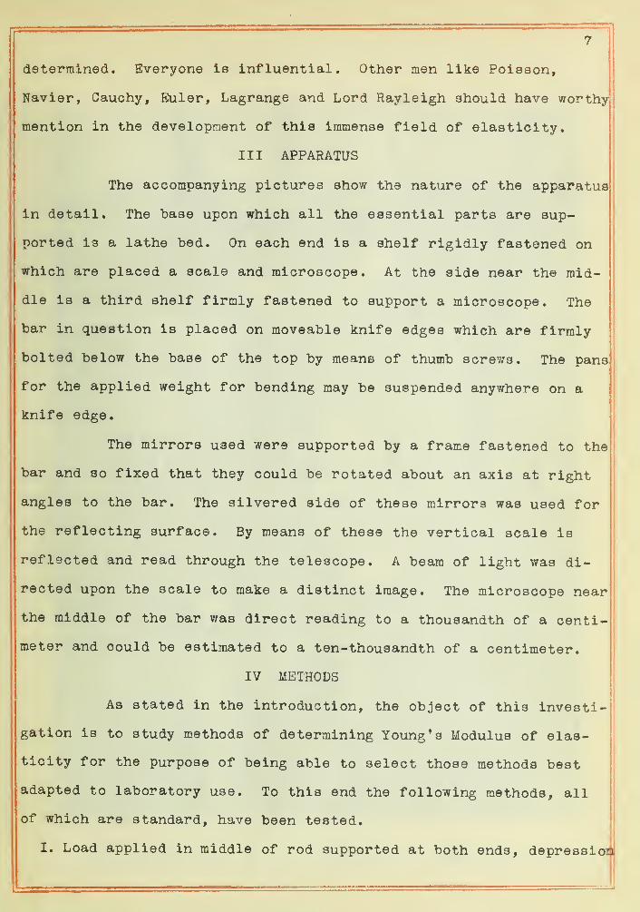
III APPARATUS
The accompanying pictures show the nature of the apparatus
in detail. The base upon which all the essential parts are sup-
ported is a lathe bed. On each end is a shelf rigidly fastened on
which are placed a scale and microscope. At the side near the mid-
dle is a third shelf firmly fastened to support a microscope. The
bar in question is placed on moveable knife edges which are firmly
bolted below the base of the top by means of thumb screws. The pans
for the applied weight for bending may be suspended anywhere on a
knife edge.
The mirrors used were supported by a frame fastened to the
bar and so fixed that they could be rotated about an axis at right
angles to the bar. The silvered side of these mirrors was used for
the reflecting surface. By means of these the vertical scale is
reflected and read through the telescope. A beam of light was di-
rected upon the scale to make a distinct image. The microscope near
the middle of the bar was direct reading to a thousandth of a centi-
meter and could be estimated to a ten-thousandth of a centimeter.
IV METHODS
As stated in the introduction, the object of this investi-
gation is to study methods of determining Young *s Modulus of elas-
ticity for the purpose of being able to select those methods best
adapted to laboratory use. To this end the following methods, all
of which are standard, have been tested.
I, Load applied in middle of rod supported at both ends, depression


8


10
of middle point measured.,
II. Load applied in middle of rod supported at both ends, deflec-
tion of "beam of light from mirrors directly over knife edge measured.
in. Load applied at ends, outside of knife edges, deflection of de-
pression measured by mirror over one knife edge and scale over the
other.
IV. Load applied at ends, outside of knife edges, depression meas-
ured at middle point.
Method I - Theory
In the first method considered the stress is applied at
the center, between the knife edges. The displacement is observed
by means of a microscope provided with a vernier. The following
drawing shows the nature and principle of the apparatus.
Fig. 1
Let AB (Fig. I ) be the rod bent by applying stress M at C.
Let P be any point on the rod, and its coordinates with respect to
the axes CX and CY through the center C be x and y. Let AB = 21. In
case any weight is applied at M each knife edge in addition to the
weight of the beam pushes up with a force of l/2 M. Hence if G be
the bending moment at P about the point B,
r
I

J'J.
G = l/2M(l-x)dynes-cm. (I)
If a tension of T dynes per square cm. is applied to each
end of a uniform bar the stress on any plane perpendicular to the
axis is a uniform tension of T dynes per square cm. The increase in
length due to the pull is in proportion to the whole length of the
rod and also to the stress applied. The ratio of the longitudinal
stress to the elongation is called Young's Modulus and is denoted
by E. That is
F = stress stress _ T (2)strain elongation e
.=1 (3)
and T = Ee. (4)
Now let ABC, Fig. 2, be a cross section of a beam with RH
in its plane and bending about it as its axis. There is one fila-
ment, the neutral filament, in the bar which is unchanged in length.
Let the plane cut it at any point 0. Then from the rectangular axes
OX and OY, parallel and perpendicular to RH draw MP and NP, the x
and y coordinates from any strained point P. Produce PM and NO cut-
ting HH' and K and R. Then MK is the radius, the distance from
the neutral filament to the axis of bending. The longitudinal fila-
ment through OM is unstretched but on passing outward the filaments
are stretched in proportion to the distance from OM. Consequently
S|, the length of any stretched portion through P, is to S its ori-
ginal length, as PK is to MK. That is
s p r
or ® =^
From (4) and (6)
T = Ee = eI (7)r


13
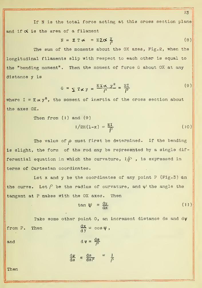
If N is the total force acting at this cross section plane
and if is the area of a filament
N = 2 T = Eld: ^ (8)
The sum of the moments about the OX axes, Fig. 2, when the
longitudinal filaments slip with respect to each other is equal to
the ""bending moment" . Then the moment of force G about OX at any
distance y is
G -;^ Toc y = - ^
where I = 5:cx:y®, the moment of inertia of the cross section about
the axes OX.
Then from ( ) ) and ( 9
)
l/2M(l-x) = % (10)I
The value of p must first be determined. If the bending
is slight, the form of the rod may be represented by a single dif-
ferential equation in which the curvature, l/f^ , is expressed in
terras of Cartesian coordinates.
Let X and y be the coordinates of any point P (Pig. 3) dn
the curve. Let be the radius of curvature, and ^ the angle the
tangent at P makes with the OX axes. Then
tan U; = ^ ( J J
)
^ dx
Take some other point 0, an increment distance ds and dy
from P. Then = cos If ,
and d vj* = ^djj/ ds = J_
ds ^ dsPf>
Then


14
Fig. 3

J d\D dll/ dx T,/ dlU1
±. — Z-X = iUz • = COS V/ -—^^ ds dx ds ^ dx
15
( J2)
Differentiating (JJ.
)
djT ^
and
— cos w —
t
dx Y dx^Substituting in (J 2)
i - «««3 d^y1 — — oos*^ -
f dx»
(13)
(14)
If y is small cos i}/' may "be replaced by unity . Consequent-
ly (14) becomes
p dP^I
Then from (15) and (10)ct^y _ 1 Mg / \
(15)
(16)
This is the differential equation from which the form of the rod
may be determined.
Integrating (16) with respect to X
(17)
where K is the constant of integration. At C (Fig. 1
)
the rod is
horizontal and x = 0, hence ^ = sind K = 0.
Integrating again
y = ^j(l/21x^ - l/ex^) -H N (IS)
N is another constant whose value is zero, for when x = the point
P moves to the OX axes, i.e., y = 0. Hence (18) becomes
(J9)
This expression is true only for CB, (Fig.l). If point P
moves to the left of OY axes X is negative and l/2Mg(l -x) becomes
l/2Mg(l+x). Consequently (19) changes to:
y - Ji£- (31x2 + 3^3)^ 12EI
(20)

f
I:
I

16
(19) and (20) are numerically equal but only opposite in signs.
If the rod (Fig.I ) is bent the depression, y, at C is
equal to the elevation, h, at B above the OX axes. But if consid-
ered here, at the knife edge, X = 1
Consequently from (19)
^ - (2J)" 6EI
3and E - ^f}" dynes per cm.^
6hl(22)
For a rectangular rod of width 2a cm. and depth 2b cm., thi^
vertical side, the moment of inertia I is
Therefore
I = i ab^ cm"^
M^l^E =
Sab^h ^y^®^ sq.cm, (24)
Method II - Theory
In this method a mirror, mounted in a suitable frame to
rotate about a horizontal axis perpendicular to the bending beam, is
clamped over each knife edge. The scale is on a shelf firmly fast-
ened at the end of the lathe bed while the telescope is on a similar
shelf at the other end. The scale is reflected by the two mirrora
Fig. 4


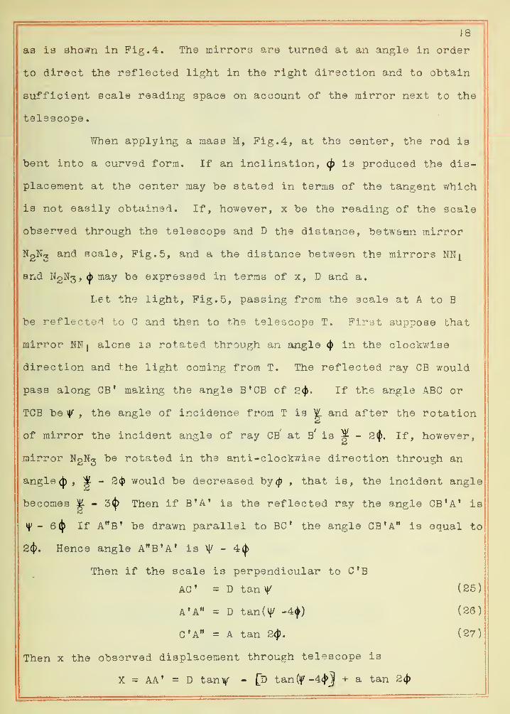
18
as is shown in Fig. 4. The mirrors are turned at an angle in order
to direct the reflected light in the right direction and to obtain
sufficient scale reading space on account of the mirror next to the
telescope.
When applying a mass M, Fig, 4, at the center, the rod is
"bent into a curved form. If an inclination, <p is produced the dis-
placement at the center may be stated in terms of the tangent which
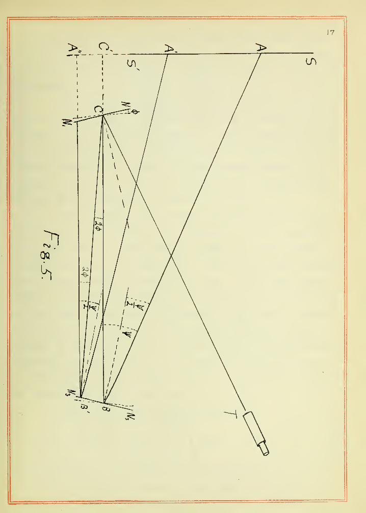
is not easily obtained. If, however, x be the reading of the scale
observed through the telescope and D the distance, between mirror
NgNj and scale. Fig. 5, and a the distance between the mirrors NNj^
and NgNg , (|)may be expressed in terms of x, D and a.
Let the light. Fig. 5, passing from the scale at A to B
be reflected to G and then to the telescope T. First suppose that
mirror NNj alone is rotated through an angle <j) in the clockwise
direction and the light coming from T. The reflected ray CB would
pass along GB' making the angle B*CB of 2<^, If the angle ABC or
TCB be , the angle of incidence from T is ^ and after the rotation
of mirror the incident angle of ray CB' at b' is ^ - 2(5. If, however,
mirror NgN^ be rotated in the anti-clockwise direction through an
angle((), ^ ~ 2^ would be decreased hy<p , that is, the incident angle
becomes |. - 3^ Then if B'A* is the reflected ray the angle GB'A' is
^' ~ 6^ If A"B' be drawn parallel to BC* the angle ca'A" is equal to
2(1). Hence angle A^B^A' is \|/ - 4(|>
Then if the scale is perpendicular to C'B
AG' = D tan V|/ (25)
A'A" = D tan{i^ -4<^) (26)
G'A" = A tan 2<)). (27)
Then x the observed displacement through telescope is
X = AA' = D tanv - Jj> tan(f-4<j>J + a tan 2(j)


19
If the deflection is very small the angle is equal to the tangent,
that is,X = 4D(/) -t- 2a(j) (28)
^ 4D+8aNow from (J7)
|i=^a..,/2.3).K (30)
where K is zero as shown above.
From Fig. 3, ^ = tangent of any angle made with the OX
axes. That is according to (4) and (6)
If the depression at the middle point C is h cm., it is
the same as the height at the knife edge B (Fig.l). Let the point
P move to B, then 1 = x and equation (?) becomes
(32)4EI
Solving for E „
^ 4I<J>~
Substituting in (33) the value (j) from (29)
E = 2f3^(2D+a) (34)
If we wish to use the entire distance between the knife
edges instead of one half of it, 1 = 21 and (34) becomes:
4 Mgl^E = —(2D+a) • (35)
If the rod has a rectangular cross-section of width 2b and vertical
depth 2d, the moment of inertia, I is
I = Id^b cm^ (36)
Therefore by substituting in (35) the value I of (36)
E = 5M&Ll(2D+a) dynes per cm.® (37)2d3b

20
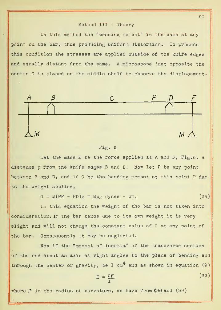
Method III - Theory
In this method the "bending moment" is the same at any
point on the bar, thus producing uniform distortion. To produce
this condition the stresses are applied outside of the knife edges
and equally distant from the same. A microscope just opposite the
center C is placed on the middle shelf to observe the displacement.
A B P D
HIF
Am mAFig. 6
Let the mass M be the force applied at A and F, Fig. 6, a
distance p from the knife edges B and D. Now let P be any point
between B and D, and if G be the bending moment at this point P due
to the weight applied,
G = M(PF - PD)g = Mpg dynes - cm. (38)
In this equation the weight of the bar is not taken into
consideration. If the bar bends due to its own weight it is very
alight and will not change the constant value of G at any point of
the bar. Consequently it may be neglected.
Now if the "moment of inertia" of the transverse section
of the rod about an axis at right angles to the plane of bending and
through the center of gravity, be I cm and as shown in equation (9)
E =I
where p is the radius of curvature, we have from (38) and (39)
(39)

E = ^gPP dynes per cm.^I
21
(40)
The value of p may be expressed in terms of the displace-
ment h as observed at the center by the microscope Let RV = 1
Fig. 7
(Pig. 7) be one half the length of the rod, SQ = 2p where p is the
radius of curvature, and SV equal the displacement h due to the
stress applied, then by geometry
1^ = h(2/? -h). (41)
But h of {2p -n) being very small as compared with 2y3, may be neg-
lected. Consequently
(42)l2" 2h
Then from (40) and (42)
_ ^gP-^ dynes per cm.^2hl
(43)
If the rod is of rectangular cross section with the hori-
zontal side, 2a cm. and vertical 2b cm. the "moment of inertia"
about an axis perpendicular to the cross section through the center
of gravity be I cm'^,
I =I ab3 (44)


Therefore substituting in (43) the value of I from (44)
_ 3 .M^pl^
E =8 ab^h
dynes per cm.
22
(45)
Method IV - Theory
In this method the experiment is the same as in Method III
except that the displacement is found by means of a mirror, the
plane of which is placed over one knife edge (Fig. 8) and scale, the
face of which is over the other knife edge. The reflection is ob-
served by a telescope placed back of the scale on a shelf firmly
fastened to the lathe bed.
Pig. 8
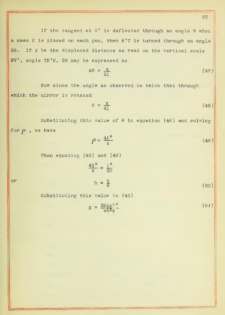
It is obvious that the tangent to the bar at the middle
point c (Fig. 8) remains always parallel to 00'. Then if the tan-
gent at 0' is deflected through an angle G when a load M is applied
at each pan, ^ being the radius of the curved rod, and 1 one-half
of the distance between the knife edges, the angle may be ex-
pressed in terms of^ and 1 as;
P - 1 (46)
r

23
If the tangent at 0' is deflected through an angle when
a mass M is placed on each pan, then N'T is turned through an angle
29. If z be the displaced distance as read on the vertical scale
NV, angle TN'N, 20 may be expressed as
20 = -Z. (47)21
Now since the angle as observed is twice that through
which the mirror is rotated
e = ^ (48)
Substituting this value of in equation (46) and solving
for 1^ , we have
41^^ (49)
Then equating (42) and (49)
111 = llz 2h
or V, - z^ ~ 8 (50)
Substituting this value in (45)
)Mpgl
"ab^zE = 5Mpg;l ^ (51)

24
V DATA
The data in Tables I, II and III was obtained by testing thi
samples according to Methods I and II, while that in Tables IV, V
and VI was obtained by Methods III and IV. In the determination of
Young* s Modulus only one sample of each of two substances, steel
and brass, was used. These bars were carefully selected in order
to secure samples of uniform dimension and without any distortion.
They were 150 cm. in length and about one square centimeter in
cross-section.
Each line of Tables II and III represent a series of read-
ings similar to that shown in Table I. The first line of Talie II
gives only the esnential terms for the forn'.ula as observed and
given in Table I. In like manner Table IV is a series of readings
for one triel determination of Young *s Modulus and is the same as
in the fourth line of Table V. The other determinations were ob-
tained in a sirrilar manner.
The observations are entered in Tables I, II, and III ac-
cording to the following notation.
Each side of cross-section of the steel bar = 2a = 2b =
.96 cm.
Each side of cross-section of the brass bar = 2a = 2b =
.95 cm.
V/eight applied = W gms.
Direct reading for applying weight = d cm.
Direct reading for removing weight - dj cm.
Difference of scale reading due to 500 gms. = T cm.
Mean of the difference of scale readings = Q, cm.
Mean of the difference for microscope = Q* cm.
I
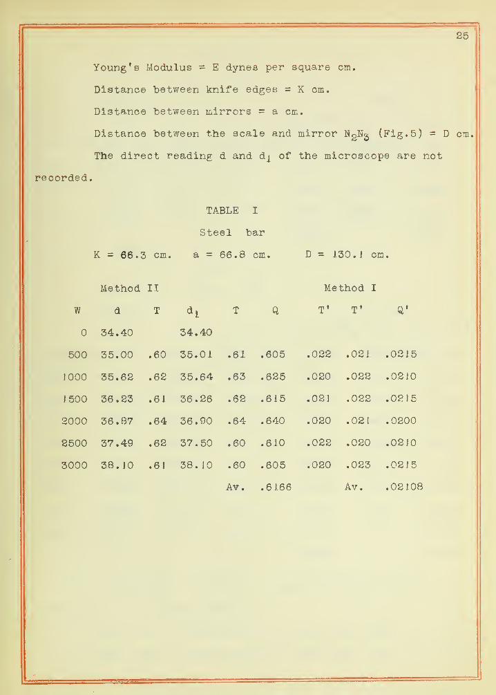
Young's Modulus = E dynes per square cm.
Distance between knife edges = K cm.
Distance between mirrors = a cm.
Distance between the scale and mirror N2N2 (Fig. 5) = D cm.
The direct reading d and dj^ of the microscope are not
recorded.
TABLE I
Steel bar
K = 66.3 cm. a = 66.8 cm. D = 130. 1 cm.
Method II Method I
w d T T Q T' Q'
34.40 34.40
500 35.00 .60 35.01 .61 .605 .022 .021 .0215
1000 35.62 .62 35.64 .63 .625 .020 .022 .0210
1 500 36.23 .61 36.26 .62 .615 .021 .022 .0215
2000 36.87 .64 36.90 .64 .640 .020 .021 .0200
2500 37.49 .62 37.50 .60 .610 .022 .020 .0210
3000 38. JO .61 38. 10 .60 .605 .020 .023 .0215
Av. .6166 Av. .02108
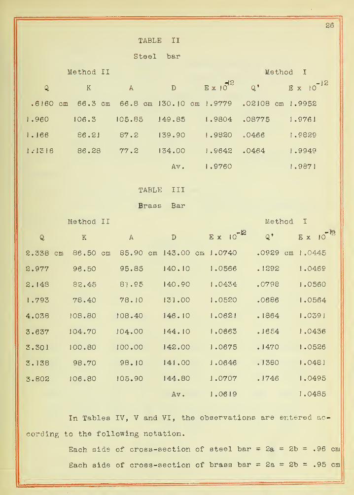
26
TABLE II
Steel bar
Method II Method I
Q K A D-12
E X 10 Q' Ex lO'^^
.6160 cm 66.3 cm 66.8 cm 130. ]0 cm 1 .9779 .02108 cm 1 .9952
1 .960 106.3 105.85 J 49. 85 1 .9804 .08775 1.9761
J . J 66 86 .2J 87.2 139.90 1 .9820 .0466 1.9829
16 86.28 77.2 134.00
Av.
1.9642
1 .9760
.0464 1.9949
1 .9871
TABLE III
Brass Bar
Method II Method I
Q K A D E X lO"^ Q* E X lo'
2.338 cm 86.50 cm 85.90 cm L43.00 cm J. 0740 .0929 cm 1 .0445
2.977 96.50 95.85 J 40 . J J .0566 .1292 1.0469
2 . ! 48 82.45 8J .95 1 40 . 90 I .0434 .0798 1.0560
1 .793 78.40 78. 10 131 .00 1.0520 .0686 1.0564
4.038 108.80 J 08. 40 1 46 . JO J .0621 .1864 1.0391
3.637 104.70 J04.00 144. 10 1 .0663 .1654 1.0436
3.301 100.80 100.00 142.00 1 .0675 .1470 1.0526
3. 138 98.70 98. 10 141 .00 J .0646 . J 380 1.0481
3.802 106.80 105.90 144.80
Av.
J .0707
1 .0619
.1746 1.0495
1 .0485
In Tables IV, V and VI, the observations are entered ac-
cording to the following notation.
Each side of cross-section of steel bar = 2a = 2b = .96
Each side of cross-section of brass bar = 2a = 2b = .95 cm
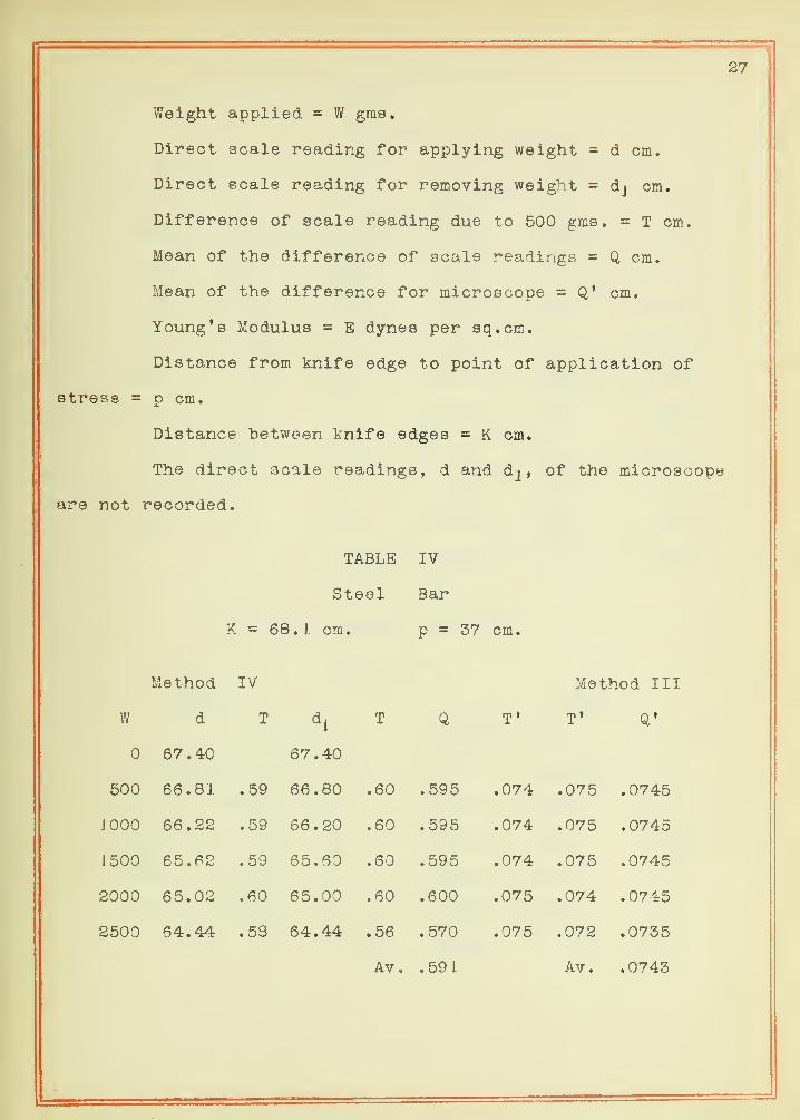
27
Weight applied = W gms.
Direct scale reading for applying weight = d cm.
Direct scale reading for removing weight = dj cm.
Difference of scale reading due to 500 gms. = T cm.
Mean of the difference of scale readings = Q cm.
Mean of the difference for microscope = Q* cm.
Young's Modulus = E dynes per sq.cm.
Distance from knife edge to point of application of
stress = p cm.
Distance between tnife edges = K cm.
The direct scale reading s, d and of the micro
not recorded.
TABLE IV
Steel Bar
K 68. J cm. p = 37 cm.
Method IV Method II
W d T d^ T Q T' T' Q»
67.40 67.40
500 66.81 .59 66.80 .60 .595 .074 .075 .0745
1000 66.22 .59 66.20 .60 .595 .074 .075 .0745
1500 65.62 .59 65.60 .60 .595 .074 .075 .0745
2000 65.02 .60 65.00 .60 .600 .075 .074 .0745
2500 64.44 .53 64.44 .56 .570 .075 .072 .0735
Av. .591 Av. .0743


TABLE V
Steel bar
Method IV
K f
.704 cm 94.13 cm 23. o cm
.7033 84.31 29 .0
.705 84.00 29 .
2
.591 68.10 37.0
.496 58.08 42.2
.440 54.05 44.0
.554 64.05 40.0
.6061 74.00 34.0
.624 74.00 34.0
Av.
TABLE
Braas
thod IV
Q K P
1 .240 cm. 74.00 cm 34 cm
1 .354 84. 12 29
1 .427 90. 12 26
1 .426 96.50 23
1.387 86.50 28
Av
.
Mp 'fVi r*/^ TTT
-12Ex !0*
2 . 084
1
•0937 cmm yj ^ Kj f will
2 . 0286 -0899 I 1 -9835
2 . 0372 . 0897 2 - 00 1
2.0 100 -0743 1 - 9953
1 . 9870 . 06 1 9 1 990 1
2.0270 .0564 1 .9723
2.0501 .071.0 2.0 181
2.065
1
0809 1 98 16
2.0483 Av. 1 .9894
VI
III
-12E X J R X in'
1 08 14 1 08 10
1 . 1014 . 1729 1.0710
1 .0654 . 1 806 1 .0522
1 .0842 .1805 I .0710
1 .0895 . 1752 1 .0 183
I . 0848 Av. 1 .0707
•12
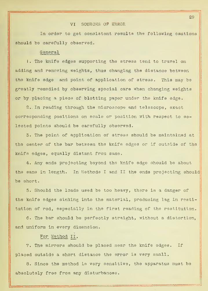
29
VI SOURCES OP ERROR i
In order to get oonaistent results the following cautions
should "be carefully observed.
General
1 . The knife edges supporting the stress tend to travel on
adding and removing weights, thus changing the distance between
the knife edge and point of application of stress. This may be
greatly remedied by observing special care when changing weights
or by placing a piece of blotting paper under the knife edge.
2. - In reading through the microscope and telescope, exact
corresponding positions on scale or position with respect to se-
lected points should be carefully observed.
3. The point of application of stress should be maintained at
the center of the bar between the knife edges or if outside of the
knife edges, equally distant from same.
4. Any ends projecting beyond the knife edge should be about
the same in length. In Methods I and II the ends projecting should
be short.
5. Should the loads used be too heavy, there is a danger of
the knife edges sinking into the material, producing lag in resti-
tution of rod, especially in the first reading of the restitution.
6. The bar should be perfectly straight, without a distortion,
and uniform in every dimension.
For Method II .
7. The mirrors should be placed near the knife edges. If
placed outside a short distance the error is very small.
8. Since the method is very sensitive, the apparatus must be
absolutely free from any disturbances.

30
9. The points of reflection on the mirrors, which are slightly
turned, must be approximately determined in order to measure the
distance between these points on the mirrors and the distance be-
tween the mirror, near the telescope and the scale.
For Method IV.
10. The plane of the mirror must be exactly over the knife edge
and perpendicular to the rod.
1 1 . The plane of the scale must be placed over the knife edge
and perpendicular to the rod.
VII CONCLUSIONS
According to this investigation these standard methods
for the determination of Young *s Modulus reveal an uniformity in
results within themselves. The averages, however, for the various
methods differ slightly from each other even though the data was
taken simultaneously. This makes it difficult to choose between
them. These differences may be attributed either to constant ex-
perimental errors or, what is more likely, to the nature of the
method of attack.
In Methods I and II, the bending being non-uniform, there-
is a changing condition of vertical shearing stresses which not
only varies constantly with the different amount of stress applied
but also with the thickness of the rod. These varying stresses are
distinctly noticeable when there is considerable of the ends of the
rod projecting beyond the knife-edges. When the stress is applied
In the middle the ends projecting over the knife-edge are subjected
to a condition which tends to prevent the rod from bending. To
make a mathematical determination of all the component forces in sud
bending would involve very complex equations of a nature beyond the


31
scope of this investigation and hence we have only a partial rnathe-
matical deduction which, however, leads to good approximate results.
In Method I where the microscope is used to measure the
deflection, the results are comparatively uniform. Having a firm
support and an instrument of high power, the displacem.ent due to the
stress can be read with satisfactory accuracy. The student, real-
izing the simplicity of the apparatus and being able to observe di-
rectly what is taking place, will understand more readily the sig-
nificance of the displacement on change of stress. The one import-
ant caution, in adjusting for a reading, is in making a definite
estimation of the relation of the mark selected on the bar to the
hair in the microscope. This objection can be greatly remedied
by making a few trial observations.
In the method using the two mirrors there are two possi-
ble advantages: (1) it is sensitive to the very slightest defor-
mation of the beam, affordins; the use of very small amounts of
stress and (2) in the use of small loads it not only prevents the
knife-edge from sinking into the sample but also overcomes the dan-
ger of passing the elastic limit of the material. There are a few
cautions to be observed. The mirrors must be placed over the knife
edge with but little of the bar projecting outside of the supports.
If there is any disturbance , as v/alking about the floor, slamming cfl'
doors of the building, or heavy traffic on streets near by, it will
set the bar to vibration, preventing any definiteness of reading of
the scale through the telescope.
In Methods III and IV applying the stress at the ends of
the bar the bending is uniform, thus eliminating the objections as
in the case of non-uniform bending as stated above. All the force
32
acting as constant component along all points of the bar, one is
able, mathematically, to account easily and accurately for the
amounts and the directions of the forces involved. There are no ap-
proximations or any small components neglected, consequently deduc-
tions made in such a manner are more accurate mathematically.
In case of finding the displacement by means of the micro-
scope, experimentally this method has the same merits as discussed
in Method I. Being of uniform bending with simple apparatus and af-
fording closer contact in the observation and reasoning of the
pupil, this method proves most sa.tiafactory
.
The last method investigated has not proved so favorable
in results and manipulation. Although the results in case of the
brass show only a small difference from the average while in case
of the steel the variation is considerably greater, there are well
grounded objections which tend to rank it low as a good method for
laboratory use. The plane of the mirror must be exactly over the
knife-edge with its normal parallel to the bar. If the bar bends
much due to its own weight, placing the plane of the mirror and lo-
cating the normal can be only approximate, which leads to serious
results. Even if the bar is perfectly straight it is a matter of a
number of trials in order to get good results. The displacement of
the bar is a factor in the denominator of the formula with a large
numerator, causing if the readings are not accurate, a marked vari-
ation in the results.
The results of this investigation indicate that Method III
ranks best for most purposes. One must conclude in its favor be-
cause not only of its complete mathematical deduction but also of
its simplicity in experimental manipulation. Method I is as good

33
except in that there is more or less of unused portions of ends
projecting beyond the knife-edges, preventing uniform bending. Meth-
od II, being very sensitive, may be highly recommended to any one
who wishes to make extensive investigation in elasticity, especial-
ly with small amount of stress. Method IV for any purpose proved
the least favorable because it is not an easy matter to ad;)ust ac-
curately the parts for the determination of the deformation of the
rod.
In conclusion I extend gratefully the most sincere thanks
to Professor A. P. Carman for his interest in this work and for
placing at my disposal materials and apparatus necessary for its
success. I am no less appreciative to Dr. E. H. Williams for the
generosity and enduring tact in his assistance to me to complete the
work of the problem.