Testing of Bolted Cold-Formed Steel Connections in Bearing ......TESTING OF BOLTED COLD-FORMED STEEL...
42
research report American Iron and Steel Institute Committee on Specifications for the Design of Cold-Formed Steel Structural Members Testing of Bolted Cold- Formed Steel Connections in Bearing (With and Without Washers) RESEARCH REPORT RP01-4 MARCH 2001
Transcript of Testing of Bolted Cold-Formed Steel Connections in Bearing ......TESTING OF BOLTED COLD-FORMED STEEL...

re
sear
ch re
port
T e s t i n g o f B o l t e d C o l d -F o r m e d S t e e l C o n n e c t i o n s i n B e a r i n g ( W i t h a n d W i t h o u t W a s h e r s )
R E S E A R C H R E P O R T R P 0 1 - 4 M A R C H 2 0 0 1
Committee on Specif ications
for the Design of Cold-Formed
Steel Structural Members
American Iron and Steel Institute

The material contained herein has been developed by researchers based on their research findings. The material has also been reviewed by the American Iron and Steel Institute Committee on Specifications for the Design of Cold-Formed Steel Structural Members. The Committee acknowledges and is grateful for the contributions of such researchers.
The material herein is for general information only. The information in it should not be used without first securing competent advice with respect to its suitability for any given application. The publication of the information is not intended as a representation or warranty on the part of the American Iron and Steel Institute, or of any other person named herein, that the information is suitable for any general or particular use or of freedom from infringement of any patent or patents. Anyone making use of the information assumes all liability arising from such use.
Copyright 2001 American Iron and Steel Institute Revised Edition Copyright 2006 American Iron and Steel Institute
TESTING OF BOLTED COLD-FORMED STEEL CONNECTIONS IN BEARING (WITH AND WITHOUT WASHERS)
Final Report
By
James A. Wallace Research Assistant
Professor R. M. Schuster
Project Director Professor R. A. LaBoube
Consultant
Canadian Cold Formed Steel Research Group
Department of Civil Engineering University of Waterloo
Waterloo, Ontario, Canada
March 2001

Abstract Contained in this report are the test results of double and single shear cold-formed steel
bolted connections failing in bearing. Connections with and without washers were studied.
The test data was compared with the current S136 and AISI methods for determining the
bearing strength of cold-formed steel bolted connections. In addition, comparisons were also
made with the new bearing approach currently being considered by AISI and with a
recommended approach resulting from this study. Calibrations in accordance with the AISI
Commentary were also carried out to establish the factors of safety and respective resistance
factors for AISI and the resistance factors for S136.

ii
TABLE OF CONTENTS
1.0 Introduction.............................................................................................................. 1
2.0 Bearing Strength Methods ....................................................................................... 1
2.1 Current S136 Approach (Clause 7.3.5.1)............................................................. 1
2.2 Current AISI Approach (Section E3.3) ................................................................ 2
2.3 Proposed AISI Method......................................................................................... 3
3.0 Testing...................................................................................................................... 5
3.1 Test Equipment .................................................................................................... 5
3.2 Specimens ............................................................................................................ 5
3.3 Method of Testing................................................................................................ 8
4.0 Test Results ............................................................................................................ 10
4.1 General ............................................................................................................... 10
4.2 Specimen Notation............................................................................................. 10
4.3 Comparisons ...................................................................................................... 13
4.4 Waterloo Method ............................................................................................... 19
4.5 Results of Waterloo Method .............................................................................. 20
4.6 Calibration.......................................................................................................... 21
5.0 Conclusions and Recommendations ...................................................................... 24
6.0 References .............................................................................................................. 25
Appendix A – Geometric Properties and Test Loads................................................... 26
Appendix B – Calculated Values and Comparisons .................................................... 30

iii
LIST OF FIGURES Figure 1: Instron Machine Model 4206 ................................................................................. 5
Figure 2: Schematic of Single Bolt Specimens...................................................................... 7
Figure 3: Schematic of Double Bolt Specimens .................................................................... 8
Figure 4: Double Shear Specimen Positioned in Test Frame ................................................ 9
Figure 5: Typical Load-Elongation Curve of Bearing Failure ............................................. 11
Figure 6: Typical Bearing failure of a Bolted Connection
[(a) Without Washers and (b) With Washers]............................................................... 11
Figure 7: Typical Bearing Failure of a Bolted Connection in Single Shear
[Without Washers] ........................................................................................................ 12
Figure 8: Typical Bearing Failure of a Bolted Connection in Double Shear
[With Washers] ............................................................................................................. 12
Figure 9: Failed Double Shear Specimens Without Washers ............................................. 13
Figure 10: Failed Double Shear Specimens With Washers ................................................ 13
Figure 11: Bearing Factor, C, for Single Shear and Outside Sheets of Double Shear Bolted
Connections With Washers ........................................................................................... 17
Figure 12: Bearing Factor, C, for Single Shear and Outside Sheets of Double Shear Bolted
Connections Without Washers ...................................................................................... 18

iv
LIST OF TABLES Table 1: Factor C, for Bearing Resistance ............................................................................. 2
Table 2: Nominal Bearing Strength for Bolted Connections With Washers Under Both Bolt
Head and Nut................................................................................................................... 3
Table 3: Nominal Bearing Strength for Bolted Connections Without Washers Under Both
Bolt Head and Nut, or With Only One Washer............................................................... 3
Table 4: Bearing Factor, C, for Bolted Connections with Washers....................................... 4
Table 5: Mechanical Properties.............................................................................................. 6
Table 6: Summary of Comparison Using Current S136 for Connections With Washers.... 14
Table 7: Summary of Comparison Using Current S136 for Connections Without Washers14
Table 8: Summary of Comparisons Using Current AISI Method for Bolted Connections in
Bearing With Washers .................................................................................................. 15
Table 9: Summary of Comparisons Using Current AISI Method for Bolted Connections in
Bearing Without Washers ............................................................................................. 15
Table 10: Summary of Comparisons Using Proposed AISI and S136 Method for Bolted
Connections in Bearing With Washers ......................................................................... 16
Table 11: Bearing Factor, C, for Data With Washers ......................................................... 19
Table 12: Bearing Factor, C, for Data Without Washers.................................................... 19
Table 13: Summary of Results Using Waterloo Method for Bolted Connections
With Washers ................................................................................................................ 20
Table 14: Summary of Results Using Waterloo Method for Bolted Connections
Without Washers ........................................................................................................... 20
Table 15: Resistance Factors and AISI Factor of Safety for Bolted Connections Failing in
Bearing using the Proposed Waterloo Methods ............................................................ 23
Table A1: Geometric Properties of Double Shear Specimens WITH WASHERS ............. 27
Table A2: Geometric Properties of Single Shear Specimens WITH WASHERS............... 28

v
Table A3: Geometric Properties of Double Shear Specimens WITHOUT WASHERS ..... 29
Table A4: Geometric Properties of Single Shear Specimens WITHOUT WASHERS....... 30
Table B1: Calculated Bearing Capacity of Specimens WITH WASHERS, using, the current
S136 Method, the Current AISI Method, and the Proposed Method ............................ 31
Table B2: Calculated Bearing Capacity of Specimens WITHOUT WASHERS, using the
current S136 Method, the current AISI Method, and the Proposed Method...................33

1
1.0 Introduction The bearing strength of bolted connections is treated differently in the two current North
American Standards for the design of cold formed steel structural members (AISI-96 [1] and
CSA S136-94 [3]), from hereon simply referred to as AISI [1] and S136 [3], respectively. In
the case of S136 [3], only one expression is presented that applies to all bolted connections
such as single and double shear, as well as, with and without washers. In AISI [1], however, a
distinction is made regarding if it is a single shear or a double shear connection and whether
or not washers are being used. More specifically, the following two categories are presented,
with and without washers:
1) Inside sheet of double shear connection
2) Single shear and outside sheet of double shear connection
Having recently carried out calibrations using the available bolted connection data found
in the published literature, it was discovered that no data exists for the case of a double shear
connection without washers where the outside sheets fail in bearing. Therefore tests were
carried out at the University of Waterloo to provide data for double shear connections. It was
also decided to test additional single shear specimens failing in bearing to add to the pool of
existing data. As well, all of these tests were duplicated with washers in order to obtain a
good comparison with the specimens without washers.
AISI [1] is currently considering a new approach for bearing of bolted connections and a
ballot has been issued for consideration. This approach is similar to what is currently
contained in S136 [3].
Contained in this report are the test results of double and single shear cold-formed steel
bolted connections failing in bearing. Connections with and without washers were studied.
The test data was compared with the current S136 and AISI methods for determining the
bearing strength of a cold-formed steel bolted connection. In addition, comparisons were also
made with the new bearing approach currently being considered by AISI and with a
recommended approach resulting from this study.
2.0 Bearing Strength Methods 2.1 Current S136 Approach (Clause 7.3.5.1)

2
Currently, the factored bearing resistance per bolt, Br, is computed in accordance with
Clause 7.3.5.1 of S136, which is presented in Equation 2.1 below. No differentiation is made
between connections using washers or not using washers. The coefficient, C, can be
considered as the bearing factor, which is a function of the ratio of the bolt diameter to the
plate thickness, d/t.
Br = φu C d t Fu (2.1)
where
C = value from Table 1 d = nominal bolt diameter t = uncoated sheet thickness Fu = tensile strength of sheet φu = resistance factor (= 0.75) Although it is recommended that a washer be used under the end of the fastener that is
turned, the values of Table 1 shall be applied whether or not washers are used. The bearing
resistance is independent of whether the thread or shank bears, or if any tension is in the
fastener.
Table 1: Factor C, for Bearing Resistance
Ratio of fastener diameter to member thickness, d/t C
d/t < 10 3
10 ≤ d/t ≤ 15 30(t/d)
d/t > 15 2
2.2 Current AISI Approach (Section E3.3)
Section E3.3 of AISI presents an approach similar to S136 to determine the nominal
bearing strength. As in S136, AISI uses a similar formulation to Equation 2.1 to determine
the nominal bearing strength. Unlike S136, AISI uses a table of nominal bearing strength
expressions containing the bearing factor, which varies from 2.22 to 3.33. Shown in Tables 2
and 3 are the nominal strength expressions for the different cases of bolted connections. The
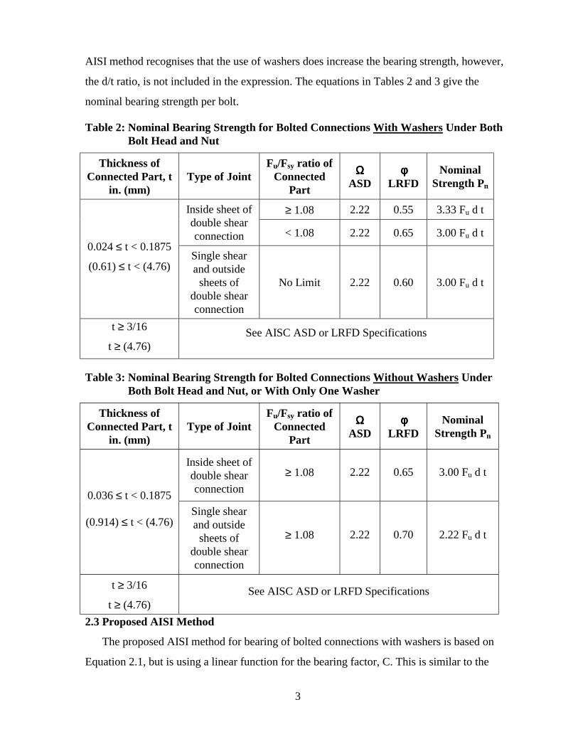
3
AISI method recognises that the use of washers does increase the bearing strength, however,
the d/t ratio, is not included in the expression. The equations in Tables 2 and 3 give the
nominal bearing strength per bolt.
Table 2: Nominal Bearing Strength for Bolted Connections With Washers Under Both Bolt Head and Nut
Thickness of Connected Part, t
in. (mm) Type of Joint
Fu/Fsy ratio of Connected
Part
ΩΩΩΩ ASD
φφφφ LRFD
Nominal Strength Pn
≥ 1.08 2.22 0.55 3.33 Fu d t Inside sheet of double shear connection < 1.08 2.22 0.65 3.00 Fu d t
0.024 ≤ t < 0.1875
(0.61) ≤ t < (4.76) Single shear and outside
sheets of double shear connection
No Limit 2.22 0.60 3.00 Fu d t
t ≥ 3/16
t ≥ (4.76) See AISC ASD or LRFD Specifications
Table 3: Nominal Bearing Strength for Bolted Connections Without Washers Under Both Bolt Head and Nut, or With Only One Washer
Thickness of Connected Part, t
in. (mm) Type of Joint
Fu/Fsy ratio of Connected
Part
ΩΩΩΩ ASD
φφφφ LRFD
Nominal Strength Pn
Inside sheet of double shear connection
≥ 1.08 2.22 0.65 3.00 Fu d t
0.036 ≤ t < 0.1875
(0.914) ≤ t < (4.76) Single shear and outside
sheets of double shear connection
≥ 1.08 2.22 0.70 2.22 Fu d t
t ≥ 3/16
t ≥ (4.76) See AISC ASD or LRFD Specifications
2.3 Proposed AISI Method
The proposed AISI method for bearing of bolted connections with washers is based on
Equation 2.1, but is using a linear function for the bearing factor, C. This is similar to the

4
approach currently used in S136. This new formulation of the bearing factor, C, is based on
the research by Rogers and Hancock [8, 9]. A distinction between connections with washers
and connections without washers is now recognised, resulting in reduced values for
connections without washers. Again, the equation defines the bearing capacity per bolt.
If washers are used, Table 4 presents the values for the bearing factor, C.
Table 4: Bearing Factor, C, for Bolted Connections with Washers
Ratio of fastener diameter to member thickness, d/t C
d/t < 10 3.0
10 ≤ d/t ≤ 22 4 – 0.1(d/t)
d/t > 22 1.8
If washers are not used, the values for the bearing factor, C, are to be taken from the
current AISI approach as shown in Table 3.

5
3.0 Testing 3.1 Test Equipment
All testing was performed on an Instron testing machine - Model 4206 (see Figure 1).
The maximum tensile capacity of the machine is 5000 kg and it is capable of providing both
digital readings and it can generate the load-elongation curve for the test specimen. This
curve can then easily be converted into a stress-strain curve.
Figure 1: Instron Machine Model 4206
3.2 Specimens
Two different thicknesses of sheet steel were used to create the specimens. Standard
coupon tests for the steel were performed, the results of which are summarised in Table 5.
Single bolt specimens were assembled and measured as per Figure 2. Multiple bolt specimens
were assembled and measured as per Figure 3. Varying the values of e, e1, and the bolt
diameter, d, created a variety of different specimen configurations. It should be noted that the
6
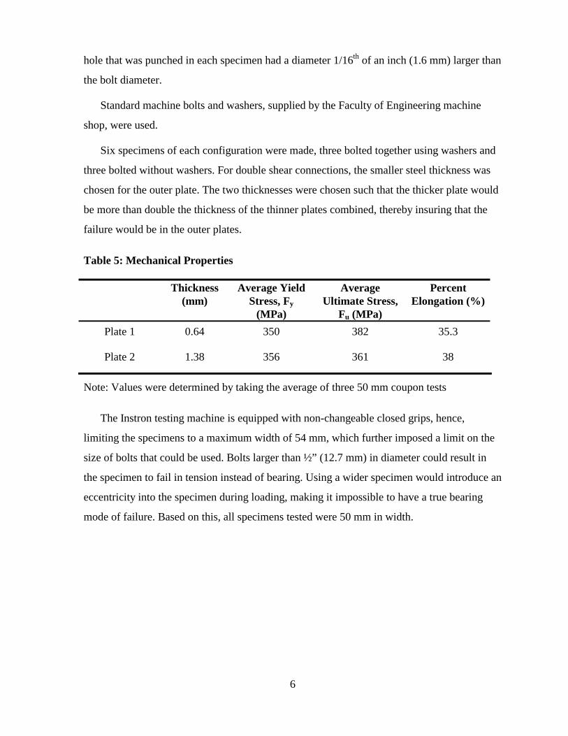
hole that was punched in each specimen had a diameter 1/16th of an inch (1.6 mm) larger than
the bolt diameter.
Standard machine bolts and washers, supplied by the Faculty of Engineering machine
shop, were used.
Six specimens of each configuration were made, three bolted together using washers and
three bolted without washers. For double shear connections, the smaller steel thickness was
chosen for the outer plate. The two thicknesses were chosen such that the thicker plate would
be more than double the thickness of the thinner plates combined, thereby insuring that the
failure would be in the outer plates.
Table 5: Mechanical Properties
Thickness (mm)
Average Yield Stress, Fy
(MPa)
Average Ultimate Stress,
Fu (MPa)
Percent Elongation (%)
Plate 1 0.64 350 382 35.3
Plate 2 1.38 356 361 38
Note: Values were determined by taking the average of three 50 mm coupon tests
The Instron testing machine is equipped with non-changeable closed grips, hence,
limiting the specimens to a maximum width of 54 mm, which further imposed a limit on the
size of bolts that could be used. Bolts larger than ½” (12.7 mm) in diameter could result in
the specimen to fail in tension instead of bearing. Using a wider specimen would introduce an
eccentricity into the specimen during loading, making it impossible to have a true bearing
mode of failure. Based on this, all specimens tested were 50 mm in width.

7
e e
S S/2
S /2
h
S ing le Shear, d ifferent th ickness
D ouble Shear
P lan
t-1
t-2
t-2
t-1
t-2
t-1 t-1
S ing le Shear, equal th ickness
Figure 2: Schematic of Single Bolt Specimens

8
e e 1 e
S S /2
S /2 h h
D o u b le S h e a r
S in g le S h e a r, d if f e r e n t t h ic k n e ss
P la n
t - 1
t - 1
t - 2
t - 2
t - 2
S in g le S h e a r, e q u a l t h ic k n e s s t - 1 t - 1
Figure 3: Schematic of Double Bolt Specimens
3.3 Testing of Specimens
Each specimen was placed in the grips of the Instron machine and a tension load was
applied until failure was reached (see Figure 4). Loading of each specimen was plotted during
testing - the applied load was plotted on the vertical y-axis and the elongation was plotted on
the horizontal x-axis. Failure of the specimen was defined as the point at which the specimen
entered into plastic deformation, which was observed as the maximum value on the load-
elongation curve. Once the applied load began to drop, even as the specimen continued to
elongate, the test was stopped. At this point, the bearing mode of failure could be clearly
identified for each specimen.

9
Figure 4: Double Shear Specimen Positioned in Test Frame

10
4.0 Test Results
4.1 General
Geometric properties and test loads of test specimens (Tables A1 and A2) and results of
specimen testing (Tables B1 and B2) can be found in the Appendices. Tables B1 and B2
include comparisons between the predicted bearing capacity and the actual bearing capacity
as tested. The preferred bearing method shall be the one that produces a
Pt/Pc (test/calculated) ratio closest to one. These comparisons are summarised in Tables 7
through 12 below.
4.2 Specimen Notation
The following notation was used to identify the test specimens:
For Single Bolt X-WW-SS-30-3/8-T15 For Double Bolt X-WW-SS-30-30-3/8
Where:
X - specimen number of a particular configuration WW - with washers; [if WO, then without washers]
SS - single shear using thicker plate; [if SST, then single shear using thinner plates; if MIX, then single shear with one thin and one thick plate]; if not given, specimen was double shear
30 - end distance in (mm) for single bolt 30 - centre to centre distance between bolts in (mm) of double bolt connection 3/8 - bolt diameter in (in.) T15 - torque applied to bolt in ft-lb; if not given, then a value of 10 ft-lb was used
4.3 Description of Typical Bearing Failure Mode
Shown in Figure 5 is a typical load-elongation curve of a bearing failure. As can be
observed from Figure 5, at initial load application some bolt slippage was experienced. This
bolt slippage was the result of the degree of bolt torque that was present in the specimen.
Following this, the specimen experienced elastic deformation (linear behaviour), which then
progressed into plastic deformation (non-linear behaviour). Failure of the specimen was
defined as the maximum load that the specimen was able to carry, which could be observed
from the load-elongation curve, as well as from the peak volt meter reading. After the
maximum load was reached, the specimen continued to deform, resulting in greatly elongated
bolt holes (See Figure 6). Once the applied load began to drop, even as the specimen

11
continued to elongate, the test was stopped. More specifically, the single shear sheets curled
outward, which was also the case with the outside sheets of the double shear specimens, as
can be observed from Figures 7 and 8, respectively.
Figure 5: Typical Load-Elongation Curve of Bearing Failure
(a) (b)
Figure 6: Typical Bearing failure of a Bolted Connection [(a) Without Washers and (b) With Washers]

12
Figure 7: Typical Bearing Failure of a Bolted Connection in Single Shear [Without Washers]
Figure 8: Typical Bearing Failure of a Bolted Connection in Double Shear [With Washers]

13
As can be observed from Figure 9, at failure the outside sheets of both single and double
shear specimens without washers conformed to the perimeter contour of the bolt head or bolt
nut. In contrast, specimens with washers conformed to the perimeter of the washers, as can be
observed from Figure 10.
Figure 9: Failed Double Shear Specimens Without Washers
Figure 10: Failed Double Shear Specimens With Washers
4.3 Comparisons

14
Summarised in Tables 6 and 7 are the comparisons of the bearing method currently used by
S136.
Table 6: Summary of Comparison Using Current S136 for Bolted Connections With Washers
Number of Specimens Average Pt/Pc
Standard Deviation
Coefficient of Variation
Single Shear Single Bolt 21 1.030 0.135 0.131
Double Shear Single Bolt 30 0.986 0.101 0.102
Double Shear Double Bolt 9 0.997 0.018 0.018
Total 60 1.003 0.108 0.107
Table 7: Summary of Comparison Using Current S136 for Bolted Connections Without Washers
Number of Specimens Average Pt/Pc
Standard Deviation
Coefficient of Variation
Single Shear Single Bolt 20 0.750 0.093 0.125
Double Shear Single Bolt 30 0.723 0.056 0.077
Double Shear Double Bolt 9 0.782 0.029 0.037
Total 59 0.741 0.071 0.095
Summarised in Tables 8 and 9 are the comparisons of the bearing method currently used by
AISI.

15
Table 8: Summary of Comparisons Using Current AISI Method for Bolted Connections in Bearing With Washers
Number of Specimens Average Pt/Pc
Standard Deviation
Coefficient of Variation
Single Shear Single Bolt 21 0.911 0.233 0.256
Double Shear Single Bolt 30 0.864 0.146 0.169
Double Shear Double Bolt 9 0.997 0.018 0.018
Total 60 0.900 0.176 0.196
Table 9: Summary of Comparisons Using Current AISI Method for Bolted Connections in Bearing Without Washers
Number of Specimens Average Pt/Pc
Standard Deviation
Coefficient of Variation
Single Shear Single Bolt 20 0.893 0.236 0.265
Double Shear Single Bolt 30 0.857 0.144 0.167
Double Shear Double Bolt 9 1.057 0.039 0.037
Total 59 0.900 0.183 0.204
Summarised in Table 10 are the comparisons of the bearing method currently proposed by
AISI method.
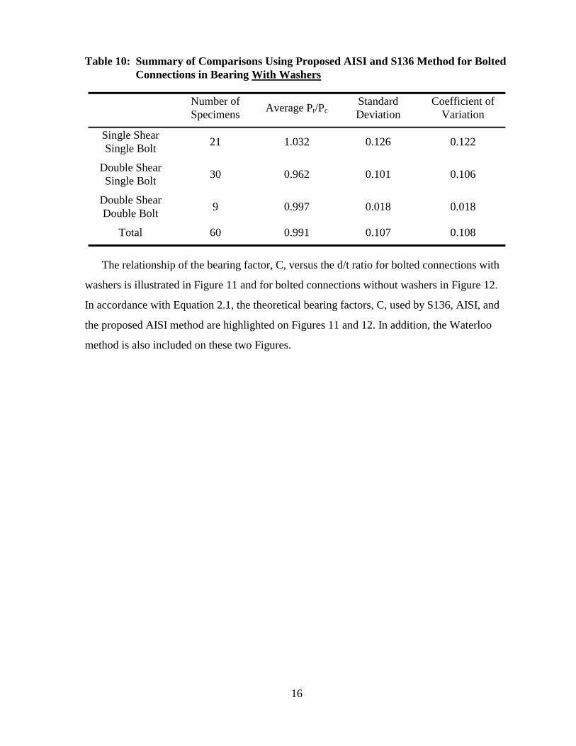
16
Table 10: Summary of Comparisons Using Proposed AISI and S136 Method for Bolted Connections in Bearing With Washers
Number of Specimens Average Pt/Pc
Standard Deviation
Coefficient of Variation
Single Shear Single Bolt 21 1.032 0.126 0.122
Double Shear Single Bolt 30 0.962 0.101 0.106
Double Shear Double Bolt 9 0.997 0.018 0.018
Total 60 0.991 0.107 0.108
The relationship of the bearing factor, C, versus the d/t ratio for bolted connections with
washers is illustrated in Figure 11 and for bolted connections without washers in Figure 12.
In accordance with Equation 2.1, the theoretical bearing factors, C, used by S136, AISI, and
the proposed AISI method are highlighted on Figures 11 and 12. In addition, the Waterloo
method is also included on these two Figures.

17
Figure 11: Bearing Factor, C, for Single Shear and Outside Sheets of Double Shear Bolted Connections With Washers

18
Figure 12: Bearing Factor, C, for Single Shear and Outside Sheets of Double Shear Bolted Connections Without Washers

19
4.4 Waterloo Method
Reviewing the three methods described in Section 2, one can observe that the current
S136 method best fits the data documented in this report for connections with washers. For
specimens tested with washers, it was determined that the current S136 method was ideal for
d/t ratios less than 15. Table 11 shows an optimized expression for determining the bearing
factor, C, for bolted connections with washers. The expression has been changed from the
current S136 approach, resulting in slightly smaller bearing factor values for large d/t ratios.
Table 11: Bearing Factor, C, for Data With Washers
Ratio of fastener diameter to member thickness, d/t C
d/t < 10 3.0
10 ≤ d/t ≤ 16.5 30/(d/t)
d/t > 16.5 1.80
For bolted connections without washers, the bearing factor, C, can be obtained from
Table 12.
Table 12: Bearing Factor, C, for Data Without Washers
Ratio of fastener diameter to member thickness, d/t C
d/t < 10 2.25
10 ≤ d/t ≤ 16.5 22.5/(d/t)
d/t > 16.5 1.35
It can be observed from Table 12 that the bearing factor, C, is 75% of the values of Table 11.

20
4.5 Results of Waterloo Method
Using the Waterloo Method, the resulting comparisons and statistical data are detailed in
Tables 13 and 14, with and without washers, respectively.
Table 13: Summary of Results Using Waterloo Method for Bolted Connections With Washers
Number of Specimens Average Pt/Pc
Standard Deviation
Coefficient of Variation
Single Shear Single Bolt 21 1.024 0.130 0.127
Double Shear Single Bolt 30 0.962 0.101 0.106
Double Shear Double Bolt 9 0.997 0.018 0.018
Total 60 0.989 0.108 0.109
Table 14: Summary of Results Using Waterloo Method for Bolted Connections Without Washers
Number of Specimens Average Pt/Pc
Standard Deviation
Coefficient of Variation
Single Shear Single Bolt 20 1.031 0.113 0.110
Double Shear Single Bolt 30 0.985 0.085 0.086
Double Shear Double Bolt 9 1.043 0.038 0.037
Total 59 1.009 0.093 0.092
From Tables 13 and 14 one can observe that the Waterloo approach gives good results for
bolted connections with washers and the best results for bolted connections without washers.

21
4.6 Calibration
Resistance factors, φ, are used with the LRFD design method in AISI [1] and the LSD
design method in S136 [3] to reduce the nominal resistances. They are determined in
conformance with load factors to provide a target reliability index, β, value of 3.5 according
to the AISI [1] provisions and 4.0 for the S136 [3] provisions.
A satisfactory design can be obtained by equating the factored resistance to the factored
loads:
φRn = c(αD Dn + αL Ln) (4.1)
Where Rn is the nominal resistance and αD and αL are the dead and live load factors,
respectively, such that the load combinations are 1.2D + 1.6L for AISI[1] and 1.25D + 1.5L
for S136[3]. The dead to live load ratios, D/L, are 1/5 in AISI[1] and 1/3 in S136[3].
Considering Equation (4.1), it can be shown that the resistance factors, φ, can be determined
as follows.
For AISI ( )
2Q
2R VV
mmm
e
FMP521.1+β
=φ (4.2)
For S136 ( )
2Q
2R VV
mmm
e
FMP420.1+β
=φ (4.3)
Where:
2F
2M
2PR VVVV ++= (4.4)
mm
2Lm
2Dm
Q LD)VL()VD(
V++
= (4.5)
Pm = mean ratio of experimental to calculated results Mm = mean ration of actual yield point to minimum specified value Fm = mean ratio of actual to specified section modulus Dm = mean dead load intensity (= 1.05 Dn
*)

22
Lm = mean live load intensity (= Ln*)
Dn = nominal dead load intensity Ln = nominal live load intensity VP = coefficient of variation of experimental to calculated results VM = coefficient of variation reflecting material properties’ uncertainties VF = coefficient of variation reflecting geometric uncertainties VD = coefficient of variation of the dead load intensities VL = coefficient of variation of the live load intensities
Since the S136 Commentary [4] does not contain a detailed description and development of
how to determine the resistance factors, it was decided to use the methodology outlined in the
AISI Commentary [2]. Hence, the values of Mm = 1.10, VM = 0.08, Fm = 1.00, and VF = 0.05
were adopted in this report and were taken from Table F1 – Statistical Data for the
Determination of Resistance Factor in AISI [1].
By knowing the resistance factor, φ, the corresponding factor of safety, Ω, can be computed
as follows:
For AISI )1L
D(
6.1LD2.1
+φ
+=Ω = 1.533/φ (4.6)
Summarised in Table 15 are the statistical values used and the corresponding factors of
safety, Ω, and resistance factors, φ, calculated for the given test data. Calibrations for S136
and AISI have only been performed for the proposed Waterloo Methods, with and without
washers.
* Values recommended by Hsiao et al. [6]
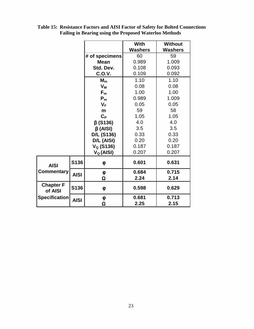
23
Table 15: Resistance Factors and AISI Factor of Safety for Bolted Connections Failing in Bearing using the Proposed Waterloo Methods
With Washers
Without Washers
# of specimens 60 59 Mean 0.989 1.009 Std. Dev. 0.108 0.093 C.O.V. 0.109 0.092 Mm 1.10 1.10 VM 0.08 0.08 Fm 1.00 1.00 Pm 0.989 1.009 VF 0.05 0.05 m 59 58 CP 1.05 1.05 ββββ (S136) 4.0 4.0 ββββ (AISI) 3.5 3.5 D/L (S136) 0.33 0.33 D/L (AISI) 0.20 0.20 VQ (S136) 0.187 0.187 VQ (AISI) 0.207 0.207
S136 φφφφ 0.601 0.631
φφφφ 0.684 0.715 AISI
Commentary AISI ΩΩΩΩ 2.24 2.14
Chapter F of AISI S136 φφφφ 0.598 0.629
φφφφ 0.681 0.713 Specification AISI ΩΩΩΩ 2.25 2.15

24
5.0 Conclusions and Recommendations The use of washers is significant in bolted connections when bearing is the mode of
failure. This distinction should be recognized in future editions of S136.
Based on this study, when single shear or outside sheets of double shear bolted
connections with washers are considered, S136 and AISI should consider adopting Equation
2.1, using the Bearing Factor, C, method as presented in Table 11.
Outside sheet failure in double shear bolted connections behave in a similar manner as
single shear connections. Based on this study, when single shear or outside sheets of double
shear bolted connections without washers are considered, it is recommended that S136 and
AISI use Equation 2.1 in conjunction with the reduced bearing factor, C, method as given in
Table 12. Alternatively, S136 and AISI could use only the bearing factor, C, method as given
in Table 11, and apply a 75 % reduction factor to the values of Table 11 for bolted
connections without washers.
25
6.0 References 1 – American Iron and Steel Institute, “Specification for the Design of Cold-Formed Steel
Structural Members”, 1996 Edition, Washington, DC, U.S.A., 1996.
2 - American Iron and Steel Institute, “Commentary of the 1996 Edition of the Cold-Formed Specification”, 1996 Edition, Washington, DC, U.S.A., 1996.
3 – Canadian Standards Association, “S136 – Cold Formed Steel Structural Members”, 1994 Edition, Toronto, ON, Canada, 1994.
4 – Canadian Standards Association, “Commentary on CSA Standard S136-94, Cold Formed Steel Structural Members”, 1995 Edition, Toronto, ON, Canada, 1995
5 – C/S96-66F AISI Committee on Specifications for the Design of Cold-Formed Steel Structural Members Subcommittee 3: Connections August, 2000 Schuster, LaBoube, Bjorhovde, Hancock
6 – Hsiao, L., Yu, W. W., Galambos, T. V., “Load and Resistance Factor Design of Cold Formed Steel, Calibration of the AISI Design Provisions”, Ninth Progress Report, Civil Engineering Study 88-2, University of Missouri-Rolla, Rolla, Missouri, U.S.A., 1998
7 – Beshara, B., “Web Crippling of Cold Formed Steel Members”, M.A.Sc. Thesis, University of Waterloo, Waterloo, Canada, 1999
8 – Rogers, C.A., Hancock, G.J., “New Bolted Connection Design Formulae for G550 and G300 Steels less than 1.0 mm Thick,” Research Report No. R769, Department of Civil Engineering, Centre for Advanced Structural Engineering, The University of Sydney, Sidney, Australia, June 1998.
9 - Rogers, C.A., Hancock, G.J., “Bolted Connection Design for Sheet Steels less than 1.0 mm Thick,” Journal of Constructional Steel Research, Vol. 51. No. 2, 123-146, 1999.

26
Appendix A – Geometric Properties and Test Loads
Table A1: Geometric Properties and Test Loads of Double Shear Specimens WITH WASHERS
Specimen Notation
Number of Bolts
Used t-1
(mm) t-2
(mm) d
(mm) d/t h (mm)
s (mm)
e (mm)
e1 (mm)
Fu (MPa)
Pt (kN)
1-ww-50 1 1.38 0.640 6.35 9.92 7.94 50 50 - 382 8.72 2-ww-50 1 1.38 0.640 6.35 9.92 7.94 50 50 - 382 8.38 3-ww-50 1 1.38 0.640 6.35 9.92 7.94 50 50 - 382 8.20 1-ww-40 1 1.38 0.640 6.35 9.92 7.94 50 40 - 382 8.16 2-ww-40 1 1.38 0.640 6.35 9.92 7.94 50 40 - 382 9.99 3-ww-40 1 1.38 0.640 6.35 9.92 7.94 50 40 - 382 9.68 1-ww-30 1 1.38 0.640 6.35 9.92 7.94 50 30 - 382 8.24 2-ww-30 1 1.38 0.640 6.35 9.92 7.94 50 30 - 382 8.32 3-ww-30 1 1.38 0.640 6.35 9.92 7.94 50 30 - 382 10.4 1-ww-20 1 1.38 0.640 6.35 9.92 7.94 50 20 - 382 8.49 2-ww-20 1 1.38 0.640 6.35 9.92 7.94 50 20 - 382 8.97 3-ww-20 1 1.38 0.640 6.35 9.92 7.94 50 20 - 382 8.60
1-ww-20-t5 1 1.38 0.640 6.35 9.92 7.94 50 20 - 382 9.09 2-ww-20-t5 1 1.38 0.640 6.35 9.92 7.94 50 20 - 382 8.50 3-ww-20-t5 1 1.38 0.640 6.35 9.92 7.94 50 20 - 382 8.38 1-ww-20-t15 1 1.38 0.640 6.35 9.92 7.94 50 20 - 382 8.81 2-ww-20-t15 1 1.38 0.640 6.35 9.92 7.94 50 20 - 382 10.2 3-ww-20-t15 1 1.38 0.640 6.35 9.92 7.94 50 20 - 382 9.27 1-ww-30-50 2 1.38 0.640 6.35 9.92 7.94 50 30 50 382 18.3 2-ww-30-50 2 1.38 0.640 6.35 9.92 7.94 50 30 50 382 18.4 3-ww-30-50 2 1.38 0.640 6.35 9.92 7.94 50 30 50 382 18.6 1-ww-30-40 2 1.38 0.640 6.35 9.92 7.94 50 30 40 382 18.5 2-ww-30-40 2 1.38 0.640 6.35 9.92 7.94 50 30 40 382 19.0 3-ww-30-40 2 1.38 0.640 6.35 9.92 7.94 50 30 40 382 18.3 1-ww-30-30 2 1.38 0.640 6.35 9.92 7.94 50 30 30 382 18.1 2-ww-30-30 2 1.38 0.640 6.35 9.92 7.94 50 30 30 382 19.1 3-ww-30-30 2 1.38 0.640 6.35 9.92 7.94 50 30 30 382 18.9 1-ww-40-3/8 1 1.38 0.640 9.53 14.9 11.1 50 40 - 382 9.64 2-ww-40-3/8 1 1.38 0.640 9.53 14.9 11.1 50 40 - 382 9.55 3-ww-40-3/8 1 1.38 0.640 9.53 14.9 11.1 50 40 - 382 10.1 1-ww-30-5/16 1 1.38 0.640 7.94 12.4 9.53 50 30 - 382 8.32 2-ww-30-5/16 1 1.38 0.640 7.94 12.4 9.53 50 30 - 382 10.5 3-ww-30-5/16 1 1.38 0.640 7.94 12.4 9.53 50 30 - 382 10.6 1-ww-50-1/2 1 1.38 0.640 12.7 12.4 14.3 50 50 - 382 14.7 2-ww-50-1/2 1 1.38 0.640 12.7 12.4 14.3 50 50 - 382 15.2 3-ww-50-1/2 1 1.38 0.640 12.7 12.4 14.3 50 50 - 382 12.8 1-ww-50-5/8 1 1.38 0.640 15.9 5.75 17.5 50 50 - 382 13.9 2-ww-50-5/8 1 1.38 0.640 15.9 5.75 17.5 50 50 - 382 14.0 3-ww-50-5/8 1 1.38 0.640 15.9 5.75 17.5 50 50 - 382 13.7 Table A2: Geometric Properties and Test Loads of Single Shear Specimens
WITH WASHERS

27
Specimen Notation
Number of Bolts
Used t-1
(mm) t-2
(mm) d
(mm) d/t h (mm)
s (mm)
e (mm)
e1 (mm)
Fu (MPa)
Pt (kN)
1-ww-ss-5/16 1 0.640 0.640 7.94 12.4 9.53 50 30 - 382 4.77 2-ww-ss-5/16 1 0.640 0.640 7.94 12.4 9.53 50 30 - 382 5.20 3-ww-ss-5/16 1 0.640 0.640 7.94 12.4 9.53 50 30 - 382 4.74 1-ww-sst-5/16 1 1.38 1.38 7.94 5.75 9.53 50 30 - 361 14.7 2-ww-sst-5/16 1 1.38 1.38 7.94 5.75 9.53 50 30 - 361 12.6 3-ww-sst-5/16 1 1.38 1.38 7.94 5.75 9.53 50 30 - 361 12.4 1-ww-sst-1/4 1 1.38 1.38 6.35 4.60 7.94 50 30 - 361 12.2 2-ww-sst-1/4 1 1.38 1.38 6.35 4.60 7.94 50 30 - 361 12.2 3-ww-sst-1/4 1 1.38 1.38 6.35 4.60 7.94 50 30 - 361 11.9 1-ww-mix-1/4 1 1.38 0.640 6.35 9.92 7.94 50 30 - 382 4.78 2-ww-mix-1/4 1 1.38 0.640 6.35 9.92 7.94 50 30 - 382 4.52 3-ww-mix-1/4 1 1.38 0.640 6.35 9.92 7.94 50 30 - 382 4.21 1-ww-ss-1/4 1 0.640 0.640 6.35 9.92 7.94 50 30 - 382 4.48 2-ww-ss-1/4 1 0.640 0.640 6.35 9.92 7.94 50 30 - 382 4.06 3-ww-ss-1/4 1 0.640 0.640 6.35 9.92 7.94 50 30 - 382 4.53 1-ww-ss-1/2 1 0.640 0.640 12.7 19.8 14.3 50 50 - 382 6.32 2-ww-ss-1/2 1 0.640 0.640 12.7 19.8 14.3 50 50 - 382 6.37 3-ww-ss-1/2 1 0.640 0.640 12.7 19.8 14.3 50 50 - 382 5.98 1-ww-ss-5/8 1 0.640 0.640 15.9 24.8 17.5 50 50 - 382 6.69 2-ww-ss-5/8 1 0.640 0.640 15.9 24.8 17.5 50 50 - 382 7.05 3-ww-ss-5/8 1 0.640 0.640 15.9 24.8 17.5 50 50 - 382 6.55

28
Table A3: Geometric Properties and Test Loads of Double Shear Specimens WITHOUT WASHERS
Specimen Notation
Number of Bolts
Used
t-1 (mm)
t-2 (mm)
d (mm) d/t h
(mm) s
(mm) e
(mm) e1
(mm) Fu
(MPa) Pt
(kN)
1-wo-50 1 1.38 0.640 6.35 9.92 7.94 50 50 - 382 6.29 2-wo-50 1 1.38 0.640 6.35 9.92 7.94 50 50 - 382 6.95 3-wo-50 1 1.38 0.640 6.35 9.92 7.94 50 50 - 382 6.53 1-wo-40 1 1.38 0.640 6.35 9.92 7.94 50 40 - 382 6.64 2-wo-40 1 1.38 0.640 6.35 9.92 7.94 50 40 - 382 6.12 3-wo-40 1 1.38 0.640 6.35 9.92 7.94 50 40 - 382 6.70 1-wo-30 1 1.38 0.640 6.35 9.92 7.94 50 30 - 382 6.38 2-wo-30 1 1.38 0.640 6.35 9.92 7.94 50 30 - 382 6.41 3-wo-50 1 1.38 0.640 6.35 9.92 7.94 50 30 - 382 6.24 1-wo-20 1 1.38 0.640 6.35 9.92 7.94 50 20 - 382 5.89 2-wo-20 1 1.38 0.640 6.35 9.92 7.94 50 20 - 382 6.20 3-wo-20 1 1.38 0.640 6.35 9.92 7.94 50 20 - 382 6.60
1-wo-20-t5 1 1.38 0.640 6.35 9.92 7.94 50 20 - 382 7.24 2-wo-20-t5 1 1.38 0.640 6.35 9.92 7.94 50 20 - 382 6.63 3-wo-20-t5 1 1.38 0.640 6.35 9.92 7.94 50 20 - 382 6.45 1-wo-20-t15 1 1.38 0.640 6.35 9.92 7.94 50 20 - 382 7.11 2-wo-20-t15 1 1.38 0.640 6.35 9.92 7.94 50 20 - 382 6.50 3-wo-20-t15 1 1.38 0.640 6.35 9.92 7.94 50 20 - 382 7.71 1-wo-30-50 2 1.38 0.640 6.35 9.92 7.94 50 30 50 382 14.5 2-wo-30-50 2 1.38 0.640 6.35 9.92 7.94 50 30 50 382 15.3 3-wo-30-50 2 1.38 0.640 6.35 9.92 7.94 50 30 50 382 14.2 1-wo-30-40 2 1.38 0.640 6.35 9.92 7.94 50 30 40 382 14.1 2-wo-30-40 2 1.38 0.640 6.35 9.92 7.94 50 30 40 382 14.6 3-wo-30-40 2 1.38 0.640 6.35 9.92 7.94 50 30 40 382 14.2 1-wo-30-30 2 1.38 0.640 6.35 9.92 7.94 50 30 30 382 15.1 2-wo-30-30 2 1.38 0.640 6.35 9.92 7.94 50 30 30 382 15.4 3-wo-30-30 2 1.38 0.640 6.35 9.92 7.94 50 30 30 382 14.0 1-wo-40-3/8 1 1.38 0.640 9.53 14.9 11.1 50 40 - 382 7.26 2-wo-40-3/8 1 1.38 0.640 9.53 14.9 11.1 50 40 - 382 7.52 3-wo-40-3/8 1 1.38 0.640 9.53 14.9 11.1 50 40 - 382 7.65 1-wo-30-5/16 1 1.38 0.640 7.94 12.4 9.53 50 30 - 382 7.82 2-wo-30-5/16 1 1.38 0.640 7.94 12.4 9.53 50 30 - 382 6.58 3-wo-30-5/16 1 1.38 0.640 7.94 12.4 9.53 50 30 - 382 6.98 1-wo-50-1/2 1 1.38 0.640 12.7 19.8 14.3 50 50 - 382 9.80 2-wo-50-1/2 1 1.38 0.640 12.7 19.8 14.3 50 50 - 382 9.62 3-wo-50-1/2 1 1.38 0.640 12.7 19.8 14.3 50 50 - 382 9.16 1-wo-50-5/8 1 1.38 0.640 15.9 24.8 17.5 50 50 - 382 10.3 2-wo-50-5/8 1 1.38 0.640 15.9 24.8 17.5 50 50 - 382 10.3 3-wo-50-5/8 1 1.38 0.640 15.9 24.8 17.5 50 50 - 382 10.3
Table A4: Geometric Properties and Test Loads of Single Shear Specimens WITHOUT WASHERS

29
Specimen Notation
Number of Bolts
Used
t-1 (mm)
t-2 (mm)
d (mm) d/t h
(mm) s
(mm) e
(mm) e1
(mm) Fu
(MPa) Pt
(kN)
1-wo-ss-5/16 1 0.640 0.640 7.94 12.4 9.53 50 30 - 382 3.23 2-wo-ss-5/16 1 0.640 0.640 7.94 12.4 9.53 50 30 - 382 3.27 3-wo-ss-5/16 1 0.640 0.640 7.94 12.4 9.53 50 30 - 382 3.39 1-wo-sst-5/16 1 1.38 1.38 7.94 5.75 9.53 50 30 - 361 9.12 2-wo-sst-5/16 1 1.38 1.38 7.94 5.75 9.53 50 30 - 361 8.51 3-wo-sst-5/16 1 1.38 1.38 7.94 5.75 9.53 50 30 - 361 8.26 1-wo-sst-1/4 1 1.38 1.38 6.35 4.60 7.94 50 30 - 361 9.16 2-wo-sst-1/4 1 1.38 1.38 6.35 4.60 7.94 50 30 - 361 8.92 3-wo-sst-1/4 1 1.38 1.38 6.35 4.60 7.94 50 30 - 361 9.03 1-wo-mix-1/4 1 1.38 0.640 6.35 9.92 7.94 50 30 - 382 3.52 2-wo-mix-1/4 1 1.38 0.640 6.35 9.92 7.94 50 30 - 382 3.47 3-wo-mix-1/4 1 1.38 0.640 6.35 9.92 7.94 50 30 - 382 3.73 1-wo-ss-1/4 1 0.640 0.640 6.35 9.92 7.94 50 30 - 382 3.27 2-wo-ss-1/4 1 0.640 0.640 6.35 9.92 7.94 50 30 - 382 3.30 1-wo-ss-1/2 1 0.640 0.640 12.7 19.8 14.3 50 50 - 382 4.25 2-wo-ss-1/2 1 0.640 0.640 12.7 19.8 14.3 50 50 - 382 4.43 3-wo-ss-1/2 1 0.640 0.640 12.7 19.8 14.3 50 50 - 382 4.00 1-wo-ss-5/8 1 0.640 0.640 15.9 24.8 17.5 50 50 - 382 5.45 2-wo-ss-5/8 1 0.640 0.640 15.9 24.8 17.5 50 50 - 382 5.43 3-wo-ss-5/8 1 0.640 0.640 15.9 24.8 17.5 50 50 - 382 5.41
30
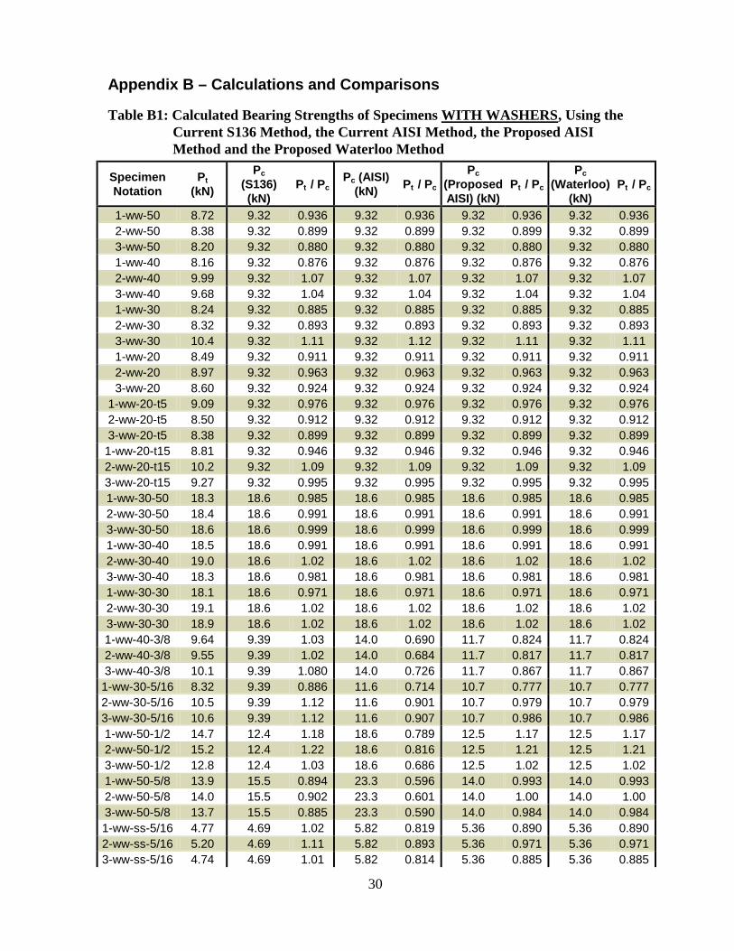
Appendix B – Calculations and Comparisons
Table B1: Calculated Bearing Strengths of Specimens WITH WASHERS, Using the Current S136 Method, the Current AISI Method, the Proposed AISI Method and the Proposed Waterloo Method
Specimen Notation
Pt (kN)
Pc (S136) (kN)
Pt / Pc Pc (AISI)
(kN) Pt / Pc Pc
(Proposed AISI) (kN)
Pt / Pc Pc
(Waterloo) (kN)
Pt / Pc
1-ww-50 8.72 9.32 0.936 9.32 0.936 9.32 0.936 9.32 0.936 2-ww-50 8.38 9.32 0.899 9.32 0.899 9.32 0.899 9.32 0.899 3-ww-50 8.20 9.32 0.880 9.32 0.880 9.32 0.880 9.32 0.880 1-ww-40 8.16 9.32 0.876 9.32 0.876 9.32 0.876 9.32 0.876 2-ww-40 9.99 9.32 1.07 9.32 1.07 9.32 1.07 9.32 1.07 3-ww-40 9.68 9.32 1.04 9.32 1.04 9.32 1.04 9.32 1.04 1-ww-30 8.24 9.32 0.885 9.32 0.885 9.32 0.885 9.32 0.885 2-ww-30 8.32 9.32 0.893 9.32 0.893 9.32 0.893 9.32 0.893 3-ww-30 10.4 9.32 1.11 9.32 1.12 9.32 1.11 9.32 1.11 1-ww-20 8.49 9.32 0.911 9.32 0.911 9.32 0.911 9.32 0.911 2-ww-20 8.97 9.32 0.963 9.32 0.963 9.32 0.963 9.32 0.963 3-ww-20 8.60 9.32 0.924 9.32 0.924 9.32 0.924 9.32 0.924
1-ww-20-t5 9.09 9.32 0.976 9.32 0.976 9.32 0.976 9.32 0.976 2-ww-20-t5 8.50 9.32 0.912 9.32 0.912 9.32 0.912 9.32 0.912 3-ww-20-t5 8.38 9.32 0.899 9.32 0.899 9.32 0.899 9.32 0.899 1-ww-20-t15 8.81 9.32 0.946 9.32 0.946 9.32 0.946 9.32 0.946 2-ww-20-t15 10.2 9.32 1.09 9.32 1.09 9.32 1.09 9.32 1.09 3-ww-20-t15 9.27 9.32 0.995 9.32 0.995 9.32 0.995 9.32 0.995 1-ww-30-50 18.3 18.6 0.985 18.6 0.985 18.6 0.985 18.6 0.985 2-ww-30-50 18.4 18.6 0.991 18.6 0.991 18.6 0.991 18.6 0.991 3-ww-30-50 18.6 18.6 0.999 18.6 0.999 18.6 0.999 18.6 0.999 1-ww-30-40 18.5 18.6 0.991 18.6 0.991 18.6 0.991 18.6 0.991 2-ww-30-40 19.0 18.6 1.02 18.6 1.02 18.6 1.02 18.6 1.02 3-ww-30-40 18.3 18.6 0.981 18.6 0.981 18.6 0.981 18.6 0.981 1-ww-30-30 18.1 18.6 0.971 18.6 0.971 18.6 0.971 18.6 0.971 2-ww-30-30 19.1 18.6 1.02 18.6 1.02 18.6 1.02 18.6 1.02 3-ww-30-30 18.9 18.6 1.02 18.6 1.02 18.6 1.02 18.6 1.02 1-ww-40-3/8 9.64 9.39 1.03 14.0 0.690 11.7 0.824 11.7 0.824 2-ww-40-3/8 9.55 9.39 1.02 14.0 0.684 11.7 0.817 11.7 0.817 3-ww-40-3/8 10.1 9.39 1.080 14.0 0.726 11.7 0.867 11.7 0.867 1-ww-30-5/16 8.32 9.39 0.886 11.6 0.714 10.7 0.777 10.7 0.777 2-ww-30-5/16 10.5 9.39 1.12 11.6 0.901 10.7 0.979 10.7 0.979 3-ww-30-5/16 10.6 9.39 1.12 11.6 0.907 10.7 0.986 10.7 0.986 1-ww-50-1/2 14.7 12.4 1.18 18.6 0.789 12.5 1.17 12.5 1.17 2-ww-50-1/2 15.2 12.4 1.22 18.6 0.816 12.5 1.21 12.5 1.21 3-ww-50-1/2 12.8 12.4 1.03 18.6 0.686 12.5 1.02 12.5 1.02 1-ww-50-5/8 13.9 15.5 0.894 23.3 0.596 14.0 0.993 14.0 0.993 2-ww-50-5/8 14.0 15.5 0.902 23.3 0.601 14.0 1.00 14.0 1.00 3-ww-50-5/8 13.7 15.5 0.885 23.3 0.590 14.0 0.984 14.0 0.984 1-ww-ss-5/16 4.77 4.69 1.02 5.82 0.819 5.36 0.890 5.36 0.890 2-ww-ss-5/16 5.20 4.69 1.11 5.82 0.893 5.36 0.971 5.36 0.971 3-ww-ss-5/16 4.74 4.69 1.01 5.82 0.814 5.36 0.885 5.36 0.885

31
Table B1: Continued
Specimen Notation
Pt (kN)
Pc (S136) (kN) Pt / Pc
Pc (AISI) (kN) Pt / Pc
Pc (Proposed AISI) (kN)
Pt / Pc Pc
(Waterloo) (kN)
Pt / Pc
1-ww-sst-5/16 14.7 11.9 1.24 11.9 1.24 11.9 1.24 11.9 1.24 2-ww-sst-5/16 12.6 11.9 1.06 11.9 1.06 11.9 1.06 11.9 1.06 3-ww-sst-5/16 12.4 11.9 1.04 11.9 1.04 11.9 1.04 11.9 1.04 1-ww-sst-1/4 12.2 9.49 1.29 9.49 1.29 9.49 1.29 9.49 1.29 2-ww-sst-1/4 12.2 9.49 1.29 9.49 1.29 9.49 1.29 9.49 1.28 3-ww-sst-1/4 11.9 9.49 1.25 9.49 1.25 9.49 1.25 9.49 1.25 1-ww-mix-1/4 4.78 4.66 1.03 4.66 1.03 4.66 1.03 4.66 1.03 2-ww-mix-1/4 4.52 4.66 0.971 4.66 0.971 4.66 0.971 4.66 0.971 3-ww-mix-1/4 4.21 4.66 0.904 4.66 0.904 4.66 0.904 4.66 0.904 1-ww-ss-1/4 4.48 4.66 0.963 4.66 0.963 4.66 1.02 4.66 0.963 2-ww-ss-1/4 4.06 4.66 0.872 4.66 0.872 4.66 0.923 4.66 0.872 3-ww-ss-1/4 4.53 4.66 0.973 4.66 0.973 4.66 1.03 4.66 0.973 1-ww-ss-1/2 6.32 6.21 1.02 9.32 0.678 6.26 1.01 6.26 1.01 2-ww-ss-1/2 6.37 6.21 1.02 9.32 0.684 6.26 1.02 6.26 1.02 3-ww-ss-1/2 5.98 6.21 0.964 9.32 0.642 6.26 0.956 6.26 0.956 1-ww-ss-5/8 6.69 7.76 0.862 11.6 0.575 6.99 0.958 6.99 0.958 2-ww-ss-5/8 7.05 7.76 0.909 11.6 0.606 6.99 1.01 6.99 1.01 3-ww-ss-5/8 6.55 7.76 0.844 11.6 0.563 6.99 0.938 6.99 0.938
Number: 60 60 60 60
Mean: 1.003 0.900 0.991 0.989 S.D.: 0.108 0.176 0.107 0.108
C.O.V.: 0.107 0.196 0.108 0.109

32
Table B2: Calculated Bearing Strengths of Specimens WITHOUT WASHERS, Using the Current S136 Method, the Current AISI Method, and the Proposed Waterloo Method
Specimen Notation
Pt (kN)
Pc (S136) (kN) Pt / Pc
Pc (AISI) (kN) Pt / Pc
Pc (Waterloo)
(kN) Pt / Pc
1-wo-50 6.29 9.32 0.675 6.89 0.912 6.99 0.900 2-wo-50 6.95 9.32 0.746 6.89 1.01 6.99 0.994 3-wo-50 6.53 9.32 0.701 6.89 0.948 6.99 0.935 1-wo-40 6.64 9.32 0.713 6.89 0.964 6.99 0.951 2-wo-40 6.12 9.32 0.657 6.89 0.888 6.99 0.876 3-wo-40 6.70 9.32 0.719 6.89 0.972 6.99 0.959 1-wo-30 6.38 9.32 0.685 6.89 0.925 6.99 0.913 2-wo-30 6.41 9.32 0.688 6.89 0.929 6.99 0.917 3-wo-50 6.24 9.32 0.670 6.89 0.905 6.99 0.893 1-wo-20 5.89 9.32 0.632 6.89 0.854 6.99 0.843 2-wo-20 6.20 9.32 0.666 6.89 0.899 6.99 0.887 3-wo-20 6.60 9.32 0.709 6.89 0.958 6.99 0.945
1-wo-20-t5 7.24 9.32 0.777 6.89 1.05 6.99 1.036 2-wo-20-t5 6.63 9.32 0.712 6.89 0.962 6.99 0.949 3-wo-20-t5 6.45 9.32 0.693 6.89 0.936 6.99 0.924 1-wo-20-t15 7.11 9.32 0.764 6.89 1.03 6.99 1.02 2-wo-20-t15 6.50 9.32 0.698 6.89 0.944 6.99 0.931 3-wo-20-t15 7.71 9.32 0.828 6.89 1.12 6.99 1.10 1-wo-30-50 14.5 18.6 0.776 13.8 1.05 14.0 1.04 2-wo-30-50 15.3 18.6 0.820 13.8 1.11 14.0 1.09 3-wo-30-50 14.2 18.6 0.760 13.8 1.03 14.0 1.01 1-wo-30-40 14.1 18.6 0.759 13.8 1.02 14.0 1.01 2-wo-30-40 14.6 18.6 0.781 13.8 1.06 14.0 1.04 3-wo-30-40 14.2 18.6 0.761 13.8 1.03 14.0 1.02 1-wo-30-30 15.1 18.6 0.811 13.8 1.10 14.0 1.08 2-wo-30-30 15.3 18.6 0.824 13.8 1.11 14.0 1.10 3-wo-30-30 14.0 18.6 0.749 13.8 1.01 14.0 0.998 1-wo-40-3/8 7.26 9.39 0.773 10.3 0.702 7.04 1.03 2-wo-40-3/8 7.52 9.39 0.801 10.3 0.728 7.04 1.07 3-wo-40-3/8 7.65 9.39 0.815 10.3 0.740 7.04 1.09 1-wo-30-5/16 7.82 9.39 0.833 8.6 0.907 7.04 1.110 2-wo-30-5/16 6.58 9.39 0.701 8.6 0.764 7.04 0.935 3-wo-30-5/16 6.98 9.39 0.744 8.6 0.811 7.04 0.992 1-wo-50-1/2 9.80 12.4 0.789 13.8 0.711 8.38 1.17 2-wo-50-1/2 9.62 12.4 0.775 13.8 0.698 8.38 1.15 3-wo-50-1/2 9.16 12.4 0.738 13.8 0.665 8.38 1.09 1-wo-50-5/8 10.3 15.5 0.664 17.2 0.598 10.5 0.984 2-wo-50-5/8 10.3 15.5 0.665 17.2 0.599 10.5 0.986 3-wo-50-5/8 10.3 15.5 0.661 17.2 0.595 10.5 0.979 1-wo-ss-5/16 3.23 4.69 0.688 4.31 0.749 3.52 0.917 2-wo-ss-5/16 3.27 4.69 0.696 4.31 0.758 3.52 0.928 3-wo-ss-5/16 3.39 4.69 0.723 4.31 0.788 3.52 0.964 1-wo-sst-5/16 9.12 11.9 0.769 8.78 1.04 8.91 1.02

33
Table B2: Continued
Specimen Notation
Pt (kN)
Pc (S136) (kN) Pt / Pc
Pc (AISI) (kN) Pt / Pc
Pc (Proposed)
(kN) Pt / Pc
2-wo-sst-5/16 8.51 11.9 0.717 8.78 0.969 8.90 0.956 3-wo-sst-5/16 8.26 11.9 0.696 8.78 0.941 8.90 0.928 1-wo-sst-1/4 9.16 9.49 0.965 7.02 1.30 7.12 1.29 2-wo-sst-1/4 8.92 9.49 0.940 7.02 1.27 7.12 1.25 3-wo-sst-1/4 9.03 9.49 0.951 7.02 1.28 7.12 1.27 1-wo-mix-1/4 3.52 4.66 0.756 3.45 1.02 3.49 1.01 2-wo-mix-1/4 3.47 4.66 0.746 3.45 1.01 3.49 0.994 3-wo-mix-1/4 3.73 4.66 0.800 3.45 1.08 3.49 1.07 1-wo-ss-1/4 3.27 4.66 0.701 3.45 0.948 3.49 0.935 2-wo-ss-1/4 3.30 4.66 0.708 3.45 0.956 3.49 0.944 1-wo-ss-1/2 4.25 6.21 0.684 6.89 0.616 4.19 1.01 2-wo-ss-1/2 4.43 6.21 0.714 6.89 0.643 4.19 1.06 3-wo-ss-1/2 4.00 6.21 0.645 6.89 0.581 4.19 0.955 1-wo-ss-5/8 5.45 7.76 0.703 8.62 0.633 5.24 1.04 2-wo-ss-5/8 5.43 7.76 0.700 8.62 0.631 5.24 1.04 3-wo-ss-5/8 5.41 7.76 0.696 8.62 0.627 5.24 1.03
Number: 59 59 59 Mean: 0.741 0.900 1.009
S.D.: 0.071 0.183 0.093 C.O.V.: 0.095 0.204 0.092

1140 Connecticut Avenue, NW
Suite 705
Washington, DC 20036
www.steel.org
Re
sea
rch
Re
po
rt R
P-0
1-4