Testing and Evaluation of a Modified Steel Post W-Beam ...
45
TEXAS TRANSPORTATION INSTITUTE TESTING AND EVALUATION OF A MODIFIED STEEL POST W-BEAM GUARDRAIL WITH RECYCLED POLYETHYLENE BLOCKOUTS by Roger P. Bligh Assistant Research Engineer and Wanda L. Menges Associate Research Specialist Project 400001-MPT Sponsored by Mondo Polymer Technologies, Inc. FEBRUARY 1997 TEXAS TRANSPORTATION INSTITUTE THE TEXAS A & M UNIVERSITY SYSTEM COLLEGE STATION, TEXAS
Transcript of Testing and Evaluation of a Modified Steel Post W-Beam ...

TEXAS TRANSPORTATION INSTITUTE
TESTING AND EVALUATION OF A MODIFIED STEEL POST W-BEAM GUARDRAIL WITH
RECYCLED POLYETHYLENE BLOCKOUTS
by
Roger P. Bligh Assistant Research Engineer
and
Wanda L. Menges Associate Research Specialist
Project 400001-MPT
Sponsored by Mondo Polymer Technologies, Inc.
FEBRUARY 1997
TEXAS TRANSPORTATION INSTITUTE THE TEXAS A & M UNIVERSITY SYSTEM
COLLEGE STATION, TEXAS

DISCLAIMER
The contents of this report reflect the views of the authors who are solely responsible for the facts and accuracy of the data, and the opinions, findings and conclusions presented herein. The contents do not necessarily reflect the official views or policies of the Mondo Polymer Technologies, Inc., Texas Transportation Institute, or Texas A&M University. This report does not constitute a standard, specification, or regulation. In addition, the above listed agencies assume no liability for its contents or use thereof. The names of specific products or manufacturers listed herein does not imply endorsement of those products or manufacturers.

TECHNICAL REPORT DOCUMENTATION PAGE
I. ~port No. 2. Oe.wemmen1 Acccu.ion No. 3. Recipient's Catalog Ntt.
FHWA-RD-97-4. Title and Subtille $. Report Date
FEBRUARY 1997 TESTING AND EVALUATION OF A MODIFIED STEEL POST W-BEAM 6. Perfonning OrgMization Code
GUARDRAIL WITH RECYCLED POLYETHYLENE BLOCKOUTS
7. Author(•) 8. Performing Q<pniutton Report No.
Roger P. Bligh and Wanda L. Menges 400001-MPT 9. Performing Organi7..ation Namo and Addtest 10. Wort Unit No.
Texas Transportation Institute NCPNo. The Texas A&M University System I I . Contract ot Grant No.
College Station, Texas 77843-3135
11. Spon!IOring Agency Name and Addre11 13. Type of Report •nd Period Con~rl.'d
Mondo Polymer Technologies, Inc. Final Report State Route 7 October 1996 through January 1997 P.O. Box 250 14. SJ!onsoring A.StneY Code
Reno, Ohio 45773
IS. S•lflrkmcntlll')' Note•
Name of contacting representative of Mondo Polymer Technologies, Inc.: David L. Tarrant Plant Manager
16. Ab:~tnlct
The Federal Highway Administration (FHWA) has formally adopted National Cooperative Highway Research Program (NCHRP) Report 350 as the new performance evaluation guidelines for highway safety featur~s. When tested according to these new guidelines, the widely used G4(1S) steel post, W-beam guardrail system failed to meet the relevant evaluation criteria. This report presents the results of a crash test on a modified G4(1 S) steel post, W-bearn guardrail system with recycled polyethylene blockouts. The recycled polyethylene blockout was judged to have met the evaluation criteria of NCHRP Report 350. This new blockout is considered suitable for use in both steel post and wood post guardrail systems.
11, Key Word.t: 13. l)i.,tribulion Statement
guardrails, offset blocks, blockouts, recycled materials, No restriction. This document, if published, is available to the polyethylene, roadside safety, crash testing public through National Technical Information Service,
5285 Port Royal Road, Springfield, Virginia 22161
19. Sec.wity Clu.1if. (al thit report) 20. Secwily <.1assi(, (o( thit pege) 21. No. of Pase• ll. Price
Unclassified Unclassified 43
Form DOT F 1700.7 (8-69)

51* (MODERN METRIC) CONVERSION FACTORS
APPROXIMATE CONVERSIONS TO 51 UNITS APPROXIMATE CONVERSIONS FROM 51 UNITS
Symbol When You Know Multiply by To Find Symbol Symbol When You Know Multiply by To Find Symbol
LENGlll L.ENGlll
in inches 25.4 millimeters mm mm millimeters 0.039 inches in ft feet 0.305 meters m m meters 3.28 f eet ft yd yards 0.914 meters m m meters 1.09 yards yd mi miles 1.61 kilometers km km kilometers 0 .621 miles mi
AREA AREA
in2 square inches 645.2 square millimeters mm2 mm2 square millimeters 0 .0016 square inches in2
ft2 square feet 0.093 square meters mz mz square meters 10.764 square feet ft2 yd2 square yards 0 .836 square meters mz mz square meters 1.195 square yards yd2 ac acres 0.405 hectares ha ha hectares 2.47 acres ac mi2 square miles 2.59 square kilometers km2 km2 square kilometers 0.386 square miles mi2
VOLUME VOLUME
fl oz fluid ounces 29.57 mi lli liters ml ml milliliters 0.034 fluid ounces fl oz gal gallons 3.785 liters L L liters 0.264 gallons gal ft3 cubic feet 0.028 cubic meters m3 m3 cubic meters 35.71 cubic feet ft3
yd' cubic yards 0.765 cubic meters m3 m3 cubic meters 1.307 cubic yards yd3
-· NOTE: Volumes greater than 1000 I shall be shown in m3. -· MASS MASS
oz ounces 28.35 grams g g grams 0 .035 ounces oz lb pounds 0 .454 kilograms kg kg kilograms 2.202 pounds lb T short tons 0 .907 megagrams Mg Mg megagrams 1.103 short tons T
(2000 lbl (or "metric ton") lor "t"l (or •t"l (or "metric ton") 12000 lbl
TEMPERATURE (exact ) TEMPERATURE (exact)
Of Fahrenheit 51F-321/9 or Celcius oc oc Celcius 1.8C+32 Fahrenheit Of temperature IF-321/1.8 temperature temperature temperature
ILLUMINATlON ILLUMINATlON
fc foot-candles 10.76 lux lx lx lux 0.0929 foot-candles fc fl foot-Lamberts 3.426 candela/m2 cd/m2 cd/m2 candela/m2 0.2919 foot-lamberts fl
FORCE and PRESSURE or STRESS FORCE and PRESSURE or STRESS
lbf poundforce 4.45 newtons N N newtons 0.225 poundforce lbf lbf/in2 poundforce per 6.89 kilopascals kPa kPa kilopascals 0.145 poundforce per lbf/in2
square inch square inch
IRev1se September 19

TABLE OF CONTENTS
I. INTRODUCTION 0 0 0 0 0 0 0 o o o o 0 o 0 0 0 0 0 0 0 0 0 0 0 0 0 0 0 0 0 0 0 0 0 0 0 0 0 0 0 0 0 0 0 0 0 0 1
ll. STUDY APPROACH 0 0 0 0 0 0 0 •• 0 0 0 o o o o o o 0 •• 0 0 0 0 0 0 • 0 0 0 0 0 • 0 0 0 0 0 0 0 0 0 0 3 TEST ARTICLE .. o 0 0 o 0 0 0 0 0 0 0 • 0 0 0 0 0 0 0 0 0 •• 0 0 0 0 0 0 • 0 0 0 0 0 • 0 0 0 0 0 0 0 0 0 3 FULL-SCALE CRASH TESTING 0 • o o •• 0 0 0 0 0 • 0 •• 0 0 0 0 • 0 0 0 0 0 0 0 0 0 0 0 0 0 0 3
Impact Conditions 0 0 0 0 0 0 0 0 0 0 0 0 0 0 •••••••••••••••••• 0 0 • 0 0 0 0 ••• 0 3 NCHRP Report 350 Evaluation Criteria .......... 0 0 0 0 • 0 0 0 0 • • • • • • • • 8
CRASH TEST AND DATA ANALYSIS PROCEDURES .................. 9 Electronic Instrumentation and Data Processing ..... 0 • • • • • • • • • • • • • • • • 9 Anthropomorphic Dummy Instrumentation 0 0 0 0 • • • 0 • • • • • • • • • • • 0 • • • • 1 0 Photographic Instrumentation and Data Processing . . . . . . . . . . . . . . . . . . 10 Test Vehicle Propulsion and Guidance . . . . . . . . . . . . . . . . . . . . . . . . . . . . 11
Ill. CRASH TEST RESULTS ..................................... 0 • • 13 TEST 400001-MPTl (NCHRP Report 350 Test Designation 3-11) ........... 13
Test Description ....................... 0 •••• 0 0 0 0 •• 0 0 0 0 • 0 0 0 0 0 13 Damage to Test Installation . . . . . . . . . . . . . . . . . . . . . . . . . . . . . . . . . . . . 13 Vehicle Damage . 0 •• 0 0 0 0 • 0 0 0 0 0 •• 0 • • • • • 0 • • • • • • • 0 • • • • • 0 0 • • • 0 0 • 22 Occupant Risk Values . . . . . . . . . . . . . . . . . . . . . . . . . . . . . . . . . . . . . . . . 22
IV. SUMMARY OF FINDINGS AND CONCLUSIONS ................ 0 •••• 29 SUMMARY OF FINDINGS .... . ..... 0 ••••••••••••••••••• 0 •• 0 0 0 0 0 29 CONCLUSIONS ..................................... 0 0 • 0 0 0 0 0 • 29
APPENDIX A - SOIL TESTING ................................ 0 0 • • • • 31
APPENDIX B - PROPERTIES OF RECYCLED POLYETHYLENE BLOCKOUT . . 35
REFERENCES ............................................ 0 0 0 0 0 0 0 39
111
LIST OF FIGURES
Figure No. Page
1 Cross section of modified guardrail system . . . . . . . . . . . . . . . . . . . . . . . . . . 4 2 Details of recycled polyethylene offset block . . . . . . . . . . . . . . . . . . . . . . . . . 5 3 Layout of the modified steel post w-beam guardrail
with recycled polyethylene blockouts . . . . . . . . . . . . . . . . . . . . . . . . . . 6 4 Test installation before test 400001 -MPT1 ..... . ..................... 7 5 Vehicle/installation geometries for test 400001-MPT1 ......... .. ....... 14 6 Vehicle before test 400001-MPT1 ......... .. ..... ... ... . ........ 15 7 Vehicle properties for test 400001-MPT1 .......................... 16 8 Sequential photographs for test 400001-MPT1
(overhead and frontal views) . . . . . . . . . . . . . . . . . . . . . . . . . . . . . . . 17 9 Sequential photographs for test 400001-MPT1
(rear view) . . . . . . . . . . . . . . . . . . . . . . . . . . . . . . . . . . . . . . . . . . . 19 10 After impact trajectory for test 400001-MPTl ....................... 20 11 Installation after test 400001-MPT1 ................ .. .... . .... .. . 21 12 Vehicle after test 400001-MPT1 ............................... . 23 13 Summary of results for test 400001-MPT1 ... ... ................... 24 14 Vehicle angular displacements for test 400001-MPT1 ......... . ..... . .. 25 15 Vehicle longitudinal accelerometer trace for test 400001-MPT1 ........... 26 16 Vehicle lateral accelerometer traces for test 400001-MPT1 .............. 27 17 Vehicle vertical accelerometer trace for test 400001-MPT1 ... .. ... .. .... 28
LIST OF TABLES
Table No. Page
1 Performance evaluation summary for test 400001-MPTl, NCHRP Report 350 test 3-11 . . . . . . . . . . . . . . . . . . . . . . . . . . . . . . 30
lV

I. INTRODUCTION
The Federal Highway Administration (FHW A) has formally adopted the new performance evaluation guidelines for highway features set forth in National Cooperative Highway Research Program (NCHRP) Report 350(1
) as a "Guide or Reference" document in Federal Register, Volume 58, Number 135, dated July 16, 1993, which added paragraph (a)(13) to 23 CFR, Part 625.5. FHWA has also mandated that, starting in September 1998, only highway safety appurtenances that have successfully met the performance evaluation guidelines set forth in NCHRP Report 350 may be used on the National Highway System (NHS) for new installations.
The most significant change made in new NCHRP Report 350 guidelines with regard to the evaluation of longitudinal barriers was the adoption of a 2000-kg pickup truck (2000P) as a design test vehicle. Since most existing longitudinal barriers were tested with a large passenger sedan according to the previous guidelines contained in NCHRP Report 230(2
), it was necessary to re-evaluate the performance of these barriers under the new guidelines.
As part of this re-evaluation process, the Federal Highway Administration (FHWA) sponsored the crash testing of many commonly used guardrail systems<3>. This testing indicated that the widely used G4(1 S) system was not in compliance with the new guidelines. This system consists of a 12-ga. W-beam rail mounted on W150x13.5 steel posts at a height of 550 mm to the center of the rail. The posts are embedded 1100 mm in the ground and are spaced at 1905 mm. Steel W150x13.5 blockouts are used between the post and the rail element in the standard design. During impact, the 2000P test vehicle rolled 90 degrees onto its side on the traffic side of the barrier.
A subsequent test of a modified G4(1 S) guardrail was successful. The modified system was identical in construction to the standard system with the exception of replacing the W150x13.5 steel blockout with a nominal I 52 nun x 203 mm wood blockout. During this test, the 2000P test vehicle remained upright and stable, and the system was judged to have met all applicable evaluation criteria.
This report presents the results of a crash test on a modified G4(1 S) steel post, W -beam guardrail system with recycled polyethylene blockouts. This system not only provides user agencies with another option for use with steel post guardrail, but also provides the additional environmental benefits associated with the use of recycled materials. The crash test performed was NCHRP Report 350 test designation 3-11, which involves a 2000-kg pickup truck (2000P) impacting the barrier at a nominal speed and angle of 100 km/h and 25 degrees, respectively. A description of the installation, results ofthe full-scale crash test, and evaluation ofthe impact performance are presented in the sections which follow.
1


II. STUDY APPROACH
TEST ARTICLE
A modified 04(1 S) W -beam guardrail system was constructed for evaluation of a recycled polyethylene offset block. The system consisted of7.6-m long, 12-gauge W-beam rail elements mounted on 1830-mm long Wl50x13.5 steel posts at a height of550 mm to the center of the rail. The steel posts were spaced 1905 mm on center and embedded 1100 mm using a drill and backfill procedure. A 2-ft auger was used to drill the holes. The holes were backfilled with a Type A crushed limestone base material having a maximum dry density of (129 lb/ft3) and an optimum moisture content of9.0 percent. The backfill material was compacted in 152 mm layers using a pneumatic tamper driven by an air compressor. The in-place density of three test holes was measured using a nuclear density gauge. The in-place measurements indicated a moisture content ranging from 6.5 to 7.4 percent and a compaction of greater than 95 percent as recommended in NCHRP Report 350. Results of the soil tests performed in conjunction with this test are given in Appendix A.
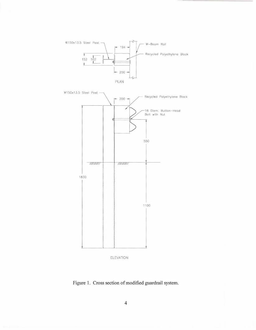
The W150x13.5 steel offset blocks used in a standard 04(18) guardrail system were replaced with 152 mm x 200 mm x 3 56 mm long molded recycled polyethylene blockouts. A cross section of the modified 04(1 S) W -beam guardrail system is shown in figure 1. A 1 02 mm wide by 6.4 mm deep channel is molded into one of the 152 mm faces of the blockout to accept the flange of the W150x13.5 steel post and prevent rotation of the blockout in field applications. A 19-mm diameter hole is drilled through the blockout and offset 44 mm from the edge of the blockout to permit attachment through the flange of the steel post. The rail, recycled polyethylene blockout, and post are connected using a single 16-mm diameter button head guardrail bolt with no washers under the head of the bolt. Details of the recycled polyethylene blockout are shown in figure 2. Various physical and mechanical properties of the recycled blockout material as reported by the manufacturer are included in Appendix B.
The completed test installation consisted of a 30.5-m long section of the modified steel post W -beam guardrail with recycled polyethylene blockouts and a flared, 11.4-m long BCTtype terminal at each end, for a total installation length of 53.3 m. The overall layout of the test installation is shown in figure 3 and photographs of the completed installation are shown in figure 4.
FULL-SCALE CRASH TESTING
Impact Conditions
Recommended procedures for the safety performance evaluation of highway features are presented in NCHRP Report 350. The test matrix for a longitudinal barrier consists of two tests:
3
W 150x 1.3.5 Steel Post
W150x13.5 Steel Post
18.30
II II II II
" " " II II II
:: II
" " " " . : " " " II II II II II II II
:: :: II II II II II II II II
:: :: II
!! " II II II II II
PLAN
W-Beom Roil
Recycled Polyethylene Block
Recycled Polyethylene Block
16 Diem. Button-Head Boll with Nut
550
1100
______ .. _______ _._
ELEVATION
Figure 1. Cross section of modified guardrail system.
4

1/2" radius, all exterior corners
l 7 7 /8"
'0"'' i i J 1~ 3 1/4" y 1 -c:::~
Plan
\ 3/ 4" dia hole
7"
+
1-3 1/4':-.j
Elevation
14
0
Isomet r ic
T
~l 1/4" _j L 7 7/8"
Side View
Figure 2. Details of recycled polyethylene offset block.
5

" I I I f ~ I I I ~ I I I I I I I I
I 11.4 m BCT
30.5 m modified w-beom 11.4 m 6CT guordroil w/polyethylene blackouts
t ~ . <:::>.,"'21 J [ b"c=>. I[ ~ ~
l'~l ~ ~~ ~ i ~ ~ ~~ ~ ~I ~
ij[ ~ ~ I'[
r~ ~1
Figure 3. Layout of the modified steel post w-beam guardrail with recycled polyethylene blockouts.

(
~·
Figure 4. Test installation before test 400001-MPTI.
7

• Test Designation 3-10- This test involves an 820-kg passenger car impacting the barrier at a nominal speed of 1 00 km/h and a nominal angle of 20 degrees. The purpose of this test is to evaluate the overall performance of the barrier section with specific attention given to occupant risk.
• Test Designation 3-11 - This test involves a 2000-kg pickup truck impacting the barrier at a nominal speed of 100 km/h and a nominal angle of 25 degrees. This test is intended to evaluate the strength of the barrier section in containing and redirecting the test vehicle. This test also examines vehicle stability and geometric compatibility with the barrier.
Because the strength and stiffness of the modified steel post barrier with recycled polyethylene blackouts is considered to be equivalent to the standard G4(1 S) guardrail system, the small car test (Test Designation 3-1 0) was considered to be unnecessary. This was based on the fact that the standard G4(1 S) guardrail was previously approved under NCHRP Report 230 which incorporated impact conditions essentially the same as those currently contained in NCHRP Report 350. Furthermore, the impact performance with the small car should be improved over that observed with the standard G4(1 S) guardrail due to the increased offset distance provided by the new recycled polyethylene blockout over the standard W150x13.5 steel block. This should reduce the interaction of the vehicle with the steel guardrail posts, thereby resulting in a smoother redirection of the vehicle.
Based on this information, only one crash test (Test Designation 3-11) was conducted for purposes of evaluating the impact performance of the recycled polyethylene blockout. This test involves a 2000-kg pickup truck impacting at the critical impact point (CIP) of the length of need section at a nominal speed and angle of 1 00 km/h and 25 degrees. In accordance with the procedures and charts set forth in NCHRP Report 350, the CIP was determined to be 4.5 m upstream of a splice.
NCHRP Report 350 Evaluation Criteria
The crash test performed in this study was evaluated in accordance with the criteria presented in NCHRP Report 350. As stated in NCHRP Report 350, "Safety performance of a highway appurtenance cannot be measured directly but can be judged on the basis of three factors: structural adequacy, occupant risk, and vehicle trajectory after collision." Accordingly, the following safety evaluation criteria from table 5.1 ofNCHRP Report 350 were used to evaluate the crash test reported herein:
• Structural Adequacy
A. Test article should contain and redirect the vehicle; the vehicle should not penetrate, underride, or override the installation although controlled lateral deflection ofthe test article is acceptable.
8

• Occupant Risk
D. Detached elements, fragments or other debris from the test article should not penetrate or show potential for penetrating the occupant compartment, or present an undue hazard to other traffic, pedestrians, or personnel in a work zone. Deformation of, or intrusions into, the occupant compartment that could cause serious injuries should not be permitted.
F. The vehicle should remain upright during and after collision although moderate roll, pitching and yawing are acceptable.
• Vehicle Trajectory
K. After collision it is preferable that the vehicle's trajectory not intrude into adjacent traffic lanes.
L. The occupant impact velocity in the longitudinal direction should not exceed 12m/sand the occupant ridedown acceleration in the longitudinal direction should not exceed 20 G's.
M. The exit angle from the test article preferably should be less than 60 percent of the test impact angle, measured at time of vehicle loss of contact with the test device.
CRASH TEST AND DATA ANALYSIS PROCEDURES
The crash test and data analysis procedures were in accordance with guidelines presented in NCHRP Report 350. Brief descriptions of these procedures are presented below.
Electronic Instrumentation and Data Processing
The test vehicle was instrumented with three solid-state angular rate transducers to measure roll, pitch and yaw rates; a triaxial accelerometer near the vehicle center-of-gravity to measure longitudinal, lateral, and vertical acceleration levels, and a back-up biaxial accelerometer in the rear of the vehicle to measure longitudinal and lateral acceleration levels. The accelerometers were strain gauge type with a linear millivolt output proportional to acceleration. ·
The electronic signals from the accelerometers and transducers were transmitted to a base station by means of constant bandwidth FMJFM telemetry link for recording on magnetic tape and for display on a real-time strip chart. Calibration signals were recorded before and after the test, and an accurate time reference signal was simultaneously recorded with the data. Pressure
9

sensitive switches on the bumper of the impacting vehicle were actuated just prior to impact by wooden dowels to indicate the elapsed time over a known distance to provide a measurement of impact velocity. The initial contact also produced an "event" mark on the data record to establish the exact instant of contact with the installation.
The multiplex of data channels, transmitted on one radio frequency, was received at the data acquisition station, and demultiplexed into separate tracks oflnter-Range Instrumentation Group (I.R.I.G.) tape recorders. After the test, the data were played back from the tape machines, filtered with anSAE J211 filter, and digitized using a microcomputer, for analysis and evaluation of impact performance.
The digitized data were then processed using two computer programs: DIGITIZE and PLOT ANGLE. Brief descriptions on the functions of these two computer programs are provided as follows.
The DIGITIZE program uses digitized data from vehicle-mounted linear accelerometers to compute occupant/compartment impact velocities, time of occupant/compartment impact after vehicle impact, and the highest 1 O-ms average ridedown acceleration. The DIGITIZE program also calculates a vehicle impact velocity and the change in vehicle velocity at the end of a given impulse period. In addition, maximum average accelerations over 50-ms intervals in each of the three directions are computed. For reporting purposes, the data from the vehicle-mounted accelerometers were then filtered with a 60 Hz digital filter and acceleration versus time curves for the longitudinal, lateral, and vertical directions were plotted using a commercially available software package (QUATTRO PRO).
The PLOT ANGLE program used the digitized data from the yaw, pitch, and roll rate transducers to compute angular displacement in degrees at 0.00067-s intervals and then instructs a plotter to draw a reproducible plot: yaw, pitch, and roll versus time. These displacements are in reference to the vehicle-fixed coordinate system with the initial position and orientation of the vehicle-fixed coordinate system being that which existed at initial impact.
Anthropomorphic Dummy Instrumentation
Use of a dummy in the 2000P test vehicle is optional according to NCHRP Report 350; therefore, no dummy was used in the test.
Photographic Instrumentation and Data Processing
Photographic coverage of the test included three high-speed cameras: one overhead with a field of view perpendicular to the ground and directly over the impact point; and one placed behind the installation at an angle; a third placed to have a field of view parallel to and aligned with the installation at the downstream end. A flash bulb activated by pressure sensitive tape switches was positioned on the impacting vehicle to indicate the instant of contact with the
10

installation and was visible from each camera. The films from these high-speed cameras were analyzed on a computer-linked Motion Analyzer to observe phenomena occurring during the collision and to obtain time-event, displacement and angular data. A Betacam, a VHS-format video camera and recorder, and still cameras were used to record and document conditions of the test vehicle and installation before and after the test.
Test Vehicle Propulsion and Guidance
The test vehicle was towed into the test installation using a steel cable guidance and reverse tow system. A steel cable for guiding the test vehicle was tensioned along the path, anchored at each end, and threaded through an attachment to the front wheel of the test vehicle. An additional steel cable was connected to the test vehicle, passed around a pulley near the impact point, through a pulley on the tow vehicle, and then anchored to the ground such that the tow vehicle moved away from the test site. A 2 to 1 speed ratio between the test and tow vehicle existed with this system. Just prior to impact with the installation, the test vehicle was released to be free-wheeling and unrestrained. The vehicle remained free-wheeling, i.e., no steering or braking inputs, until the vehicle cleared the immediate area of the test site, at which time brakes on the vehicle were activated to bring it to a safe and controlled stop.
11


Ill. CRASH TEST RESULTS
TEST 400001-MPT1 (NCHRP Report 350 Test Designation 3-11)
A 1992 Chevrolet 2500 pickup truck, shown in figures 5 and 6, was used for the crash test on the standard W-beam guardrail system on steel posts with plastic blockouts. Test inertia weight of the vehicle was 2000 kg, and its gross static weight was 2000 kg. The height to the lower edge of the vehicle bumper was 415 mm and it was 640 mm to the upper edge of the bumper. Additional dimensions and information on the vehicle are given in figure 7. The vehicle was directed into the installation using the cable reverse tow and guidance system, and was released to be free-wheeling and unrestrained just prior to impact.
Test Description
The vehicle, traveling at 100.93 kmlh, impacted the modified steel post W-beam guardrail system with recycled polyethylene blockouts 800 mm upstream of post 9, or 4.5 m upstream of the splice at the one-third point of the installation, at 25.26 degrees. Approximately 0.026 s after impact, the left front comer of the vehicle bumper reached the first post after impact (i.e., post 9), and at 0.050 s, the vehicle began to redirect. The front of the vehicle contacted post 10 at 0.101 s, and post 11 at 0.198 s. At 0.275 s, the left front comer of the vehicle contacted post 12. The vehicle was traveling parallel with the guardrail at 0.297 sat a speed of70.82 kmlh. At 0.360 s, the left front comer of the vehicle contacted post 13, followed by contact with post 14 at 0.464 s. The vehicle lost contact with theW-beam rail element near post 14 at 0.798 s while traveling at a speed of 46.12 kmlh and at an exit angle of 13.40 degrees. Immediately upon loss of contact with the guardrail, the vehicle steered back toward the guardrail. A secondary impact with the guardrail occurred at 2.044 s between posts 23 and 24. The vehicle subsequently came to rest against the guardrail 36 m downstream from the point of impact. Sequential photographs of the test period are shown in figures 8 and 9.
Damage to Test Installation
Damage to the guardrail system is shown in figures 10 and 11. The buffer end of the BCT-type terminal was pulled away from post 1 and post 1 had moved 40 mm longitudinally toward the point of impact from the tensile forces generated in the rail and transmitted to the anchorage system. The recycled polyethylene blockout at post 7 was canted and the post had displaced 135 mm in the longitudinal direction. Post 8 deflected 90 mm laterally and 10 mm longitudinally, and the guardrail bolt was pulled through the rail element. Post 9 deflected 295 mm laterally and the bolt was partially pulled through the rail element. Post 10 was rotated approximately 90 degrees at the ground line and was deflected rearward 290 mm. Post 11 was rotated 180 degrees at the ground line and had a permanent deflection of250 mm. The recycled polyethylene blockouts at posts 10 and 11 became detached from the rail when the guardrail bolts pulled through the rail element and subsequently failed at the connection to the steel post.
13

Figure 5. Vehicle/installation geometries for test 400001-MPTl.
14

Figure 6. Vehicle before test 400001-MPTl.
15

DATE: _.....] _._1_- __.1'-'3"----"'-9 -"'6-- TEST NO. : 400001-MPT1 VIN NO.: _1.~..,;G....,.C .... G"-C<J.2-"4LLK,_,O..uNL.U..E..L1...,3""0""'9'-"5L1L__ _ _ _
YEAR: ___,_] -""9_..9'""2 ____ _ MAKE: _ __,C...:h~..~..~<.e:J..vuro..(JILJ;;ew_t _ _ __ _ MODEL: --"'2-'"'5"-Q~OL.._I.p_,jL.!.I.LJ ___ _____ _
TIRE INFLATION PRESSURE: - ---- - ODOMETER: _ _ JJ....:4:L6!oLL..7...,8""0'--- --- TIRE SIZE: LT 245 - 75R 1 6
MASS DISTRIBUTION (kg) LF _5..l.,J_ __ RF_~5c4:t..:4:t...._ _ _ LR ___4.3.=t4 _ _ RR_----!4"-'4""9"'------
DESCRIBE ANY DAMAGE TO VEHICLE PRIOR TO TEST:
e Denotes accelerometer loc a tion .
NOTES: 60 mm to the Left n= ··-
[ ·~ ~~==~~~======~~~==~~~===·==~---J-0~~~~ ENGINE TYPE:----'-'8---"c,_y.y.LI ---
ENGINE CID: __,5 ........ 7_.l ___ _
TRANSMISSION TYPE:
TEST IN(l\TIAl C.M,
~~--------~--~ 0
~~----"'-!-"~· 1 ~------- c-----~--M, M,
GEOMETRY - (mm)
A 18ZO E 1260 1045 N 1610 B Z50 F _5_3_6_5, __ K 640 0 1615 c 3355 G 148 1 2 Z5 p Z65 D 1815 H M 4 15 0 445
TEST MASS - (kg) CURB INERTIAL
M, ] ] 84 11lZ Mz 843 883 MT 202Z 2000
R
s
X AUTO
_ MANUAL
OPTIONAL EQUIPMENT:
DUMMY DATA:
TYPE: N /A
MASS: N /A
SEAT POSITION:_N"'+/..cA,_ __
zoo 920
14ZO u 4040
GROSS STATIC
N/A '
N/A
N/A '
Figure 7. Vehicle properties for test 40000 1-MPTl .
16

0.000 s
0.060 s
0.120 s
0.241 s
Figure 8. Sequential photographs for test 400001-MPTI (overhead and frontal views).
17

0.362 s
0.483 s
0.640 s
0.797 s
Figure 8. Sequential photo graphs for test 40000 1-MPT 1 (overhead and frontal views) (continued).
18

0.000 s 0.362 s
0.060 s
0.120 s 0.640 s
0.241 s 0.797 s
Figure 9. Sequential photographs for test 400001-MPT 1 (rear view).
19

Figure 10. After impact trajectory for test 40000 1-MPT1.
20

Figure 11. Installation after test 40000 1-MPTl.
21

Before they failed, the bolts were partially pulled through the blockouts. At post 12, the rail element was detached and the guardrail bolt was deformed, but the plastic blockout remained attached. The post itself was rotated 180 degrees and was deflected laterally 300 mm. Post 13 was rotated 90 degrees and had a permanent deflection of290 mm. The recycled polyethylene blockout was still attached to the post, but was detached from the rail element. The blockout at post 14 was also detached from the rail and the post was deflected rearward 230 mm. All detached elements remained in close proximity to the test installation. Length of contact of the vehicle with theW -beam rail was 10.3 m. Maximum dynamic deflection during the test was 1.13 m and the maximum permanent deformation was 0.72 m.
Vehicle Damage
As shown in figure 12, the vehicle received relatively minimal damage. The left side tie rod ends, the left A-arms and spindle, and the left side frame were bent. Also damaged were the bumpers, the left side, and the left front tire and rim. Maximum deformation to the exterior of the vehicle was 490 mm near the top of the front bumper. There was no deformation or intrusion into the occupant compartment.
Occupant Risk Values
Data from the accelerometer located at the vehicle center-of-gravity were digitized for evaluation of occupant risk and were computed as follows. In the longitudinal direction, the occupant impact velocity was 6.74 m/s at 0.196 s, the highest 0.010-s occupant ridedown acceleration was -9.08 g from 0.210 to 0.220 s, and the maximum 0.050-s average acceleration was -5.12 g between 0.113 and 0.163 s. In the lateral direction, the occupant impact velocity was -4.30 m/s at 0.152 s, the highest 0.010-s occupant ridedown acceleration was 6.86 g from 0.157 to 0.167 s, and the maximum 0.050-s average was 4.42 g between 0.242 and 0.292 s. These data and other pertinent information from the test are summarized in figure 13. Vehicle angular displacements are displayed in figure 14. Vehicular accelerations versus time traces are presented in figures 15 through 17.
22

Figure 12. Vebicle after test 40000 l-MPT 1.
23

-
0.000 s 0.120 s 0.362 s
t--------------36.6 f') ------- --------1
N General Information ~ Test Agency . . . . . . . • . . . Texas Transportation Institute
Test No. . . . . . . . . . . • . . . 400001-MPT1 Date . . . . . . . . . . . . • . . . 11 / 13/ 96
Test Article Type ....... ..... . . . . Name .. ..... ...... .. . Installation Length (m) Size and/or dimension
and material of key elements ....... .... .
Soil Type and Condition .... . Test Vehicle
Guardrail W-beam w/polyethylene blockouts 53.3
Standard W-beam guardrail on steel posts with polyethylene blockouts Standard soil, dry
Type . . . . . . . • . • . . . . . . Production Designation . . . . . • . . . . . . 2000P Model . . . . . . . . • . . . . . . 1 992 Chevrolet 2500 pickup Mass (kg) Curb . . . . . . . . . 2027
Test Inertial . . . . 2000 Dummy . . . . . . . No dummy Gross Static . . . . 2000
Impact Conditions Speed (km/h) .. .. ..... • . Angle (deg) ........... • .
Exit Conditions
100.93 25 .26
Speed (km/h) . . . . . . . . . • . 46. 1 2 Angle (deg) . . . . . . . . . . . • . 13.40
Occupant Risk Values Impact Velocity (m/s)
x-direction . . . . . . . . . . . . . 6 . 7 4 y-direction . . . . . . . . . . . . . 4 .30
Ridedown Accelerations (g's) x-direction . . . . . . . . . . . . . -9.80 y-direction . . . . . . . . . . . . . 6.86
Max. 0.050-s Average (g 's) x-direction . . . . . . . . . . . . . -5. 12 y-direction . . . • . • . . . . . . . 4.42 z-direction . . . • . • . • . . . . . 3.57
Figure 13. Summary of results for test 40000 1-MPTl.
Test Article Deflections (m) Dynamic . ... ..... . Permanent ... ... • .
Vehicle Damage Exterior
VDS ... ... . . ... • ... CDC ... ...... ... .. .
Maximum Exterior Vehicle Crush (mm) .. • .
Interior
1.13 0.72
11LFQ3 11FLEW3
490
OCDI . . . . . . . . . . . . . . FSOOOOOOO Max. Occ. Compart.
Deformation (mm) 0
Post-Impact Behavior (during 1 .0 s after impact} Max. Roll Angle (deg} . . . . . 43 Max. Pitch Angle (deg} . . . . -3 Max. Yaw Angle (deg) . . . . -5

N t.h
Crash Test 400001-MPTl Vehicle Mounted Rate Transducers
50 -c------~---c---------~---------,------~~. I
I I I I
t---------------L---------------~---------------~---------------
1
40 -~---------------~---------------,-- -----------I
I I
---~---------------~-------
30 I I ---------------y------ --------,---------------~----------------
1 I
---------------~--- -----------~---------------~---------------
20 I ---------------~---------------
Yaw - - - Pitch -- Roll ] ______ _
I 10- ----------- ___ i _______________ J---------------~---------------
1 I I
------~---------------~---------------~----------
' I I I
I ~ ~, ~. ~, ~----- 1
0 ~~:"::' ;('-''--':C~' 0::_-/- ~J;~_:_::c::c- c~oe-· 'c ~<::-1 t- --- --- --- ----- ~ -- --- -~--/-- ~ --- -- ----- ----- ~- --- -- -------- --1
I I -10 -~-----------+----------~-----------+
0 0.5 1 Time After Impact (seconds)
Figure 14. Vehicle angular displacements for test 400001-MPTI.
Axes are vehicle-fixed. Sequence for determining orientation is:
1. Yaw 2. Pitch 3. Roll

20
10 ~ Ul
-bi)
'-" ~ 0 ...... ~ .... II) -II) u
0 u ~ -('j
N ~ ...... 0', '"d
;::l +-' ...... bi) ~ 0 ~
-10
-20
Crash Test 400001-MPTl Accelerometer at center-of-gravity
I Test Article:
l ________ L ________ I _______ - -l _ - - _ - __ - L - - _ - _
I
I I I I
I II II II ~ I
I
I I I - --- - -- --I - ------- : - - --- - - -~-- --- -- - I --- - - l I I ' I I I
Test Vehicle:
Test Inertial Weight:
Gross Static Weight:
Test Speed:
Test Angle:
I
0 0.1 0.2 0.3 0.4 0.5 0.6 Time After Impact (seconds)
Modified Steel Post W-Beam Guardrail
with recycled polyethylene blackouts
1992 Chevrolet 2500 pickup (2000P)
2000 kg
2000 kg
100.93 km/h
25.26 degrees
0.7 0.8 0.9
,__ 60-Hz Filter - 50-ms Average
Figure 15. Vehicle longitudinal accelerometer trace for test 400001-MPTI.
I
II I I r -1 I I
I I 1- J I I

20
10
~ rn
-OJ)
"-" ~ 0 ......
&J 1-; il)
0 ......... il) (.) (.)
~ 1'-J ......... -......) C\:S
1-; il)
&J .....:l
-10
-20
0
Crash Test 400001-MPTl Accelerometer at center-of-gravity
1Test Article: I
I I I ________ L ________ I ________ _l ________ L ____ -~
I I ' I I , I
I I
Test Vehicle:
Test Inertial Weight:
Gross Static Weight: I ---------- -- - - - - Test Speed:
Test Angle:
I I
Modified Steel Post W-Beam Guardrail
with recycled polyethylene blackouts
1992 Chevrolet 2500 pickup (2000P)
2000 kg
2000 kg
100.93 km/h
25 .26 degrees L_____ __________________________________________________ ~
- - - - - - -I- - - - - - - ·- -+ - - - - - - - f- - - ---~--------+--------~-------~--------+--------
I
I i I I ---------------1
-------1----------------~--------1--------,--------------
I
- - - - - - - - f--- - - - - - - - -I- - - - - - - - -t- - - - - - - - - f--- - - - - - - - -I- - - - - - - - + - - -- - - - - - '--- - - - - - - - -1- - - - - - - - + - - - - - - - -
I I
0.1 0.2 0.3 0.4 0.5 0.6 0.7 Time After Impact (seconds)
-- 60-Hz Filter - 50-ms Average
Figure 16. Vehicle lateral accelerometer trace for test 400001-MPTl.
0.8 0.9
I
I

r--_ ell
-bJ)
'-' :::::: 0 ....... ~ ;..., I!) -I!) () ()
~ N -ro CX! () .......
~ I!)
>
Crash Test 400001-MPTl Accelerometer at center of gravity
20 -,----------,-
15
10
5
0
-5
-10 ________ _, _ _ _ _ _ _ _ _ _ ______ _, _____ ~ with recycled polyethylene blackouts
1 1 1 Test Vehicle: 1992 Chevrolet 2500 pickup (2000P)
1
,
1
, I 2ooo kg Test Inertial Weight:
-15 _______ ~ ________ ~ ________ ; ________ ~ _____ J Gross Static Weight: 2000 kg I
1 1 1 1 Test Speed: 100.93 km/h 1-l I Test Angle: 25.26 degrees 1 I
~--------------------------------------~ I
-20
0 0.1 0.2 0.3 0.4 0.5 0.6 0.7 0.8 0.9 Time After Impact (seconds)
--- 60-Hz Filter - 50-ms Average
Figure 17. Vehicle vertical accelerometer trace for test 400001-MPTl.

IV. SUMMARY OF FINDINGS AND CONCLUSIONS
SUMMARY OF FINDINGS
The modified steel post W -beam guardrail system with recycled polyethylene blackouts is judged to have met the performance evaluation criteria ofNCHRP Report 350. The recycled polyethylene blackouts maintained their structural integrity and successfully fulfilled their intended function of providing separation between the rail and posts. The guardrail system successfully contained and redirected the test vehicle through controlled lateral deflection. The vehicle remained upright and stable throughout the impact sequence and did not show potential for penetrating, underriding or overriding the installation. The detaehed elements from the installation did not penetrate nor show potential for penetrating the occupant compartment, nor did they present undue hazard to others in the area. There was no deformation or intrusion of the occupant compartment. The vehicle did not intrude into adjacent traffic lanes and it came to rest against the guardrail after a secondary impact with the system. Occupant risk factors were well within the recommended limits specified in NCHRP Report 350. Additionally, the exit angle at loss of contact with the guardrail was less than 60 percent of the impact angle.
CONCLUSIONS
As shown in table 1, the modified steel post W-beam guardrail system with recycled polyethylene blackouts met all evaluation criteria set forth in NCHRP Report 350 for test designation 3-11. The blackouts maintained their structural integrity during the impact event and demonstrated their crashworthiness in steel post guardrail systems. Based on the results of the crash test reported herein, the recycled polyethylene blackouts manufactured by Mondo Polymer Technologies, Inc. are also considered to be a suitable replacement or alternative to the 152 mm x 203 mm x 356 mm long blackouts used in the G4(2W) wood post W-beam guardrail system.
29

w 0
I
Table 1. Performance evaluation summary for test 400001-MPT1, NCHRP Report 350 test 3-11.
Test Agency: Texas Transportation Institute Test No.: 400001-MPT1 Test Date: 11113/96
NCHRP Report 350 Evaluation Criteria I Test Results I Assessment I Structural Adequacy A. Test article should contain and redirect the vehicle; the vehicle The standard W-bearn guardrail system on
should not penetrate, underride, or override the installation steel posts with plastic blackouts contained although controlled lateral deflection of the test article is and redirected the vehicle through controlled
Pass acceptable. lateral deflection; the vehicle did not penetrate, underride, or override the installation.
Occupant Risk D. Detached elements, fragments or other debris from the test article Detached elements did not penetrate nor show
should not penetrate or show potential for penetrating the potential for penetrating the occupant occupant compartment, or present an undue hazard to other traffic, compartment, or presenting undue hazard to
Pass pedestrians, or personnel in a work zone. Deformations of, or others in the area. There was no deformation intrusions into, the occupant compartment that could cause serious or intrusion of the occupant compartment. injuries should not be permitted.
F. The vehicle should remain upright during and after collision The vehicle remained upright and stable both Pass although moderate roll, pitching and yawing are acceptable. during and after the collision.
Vehicle Trajectory
K. After collision, it is preferable that the vehicle's trajectory not The vehicle came to rest against the test intrude into adjacent traffic lanes. installation and did not intrude into adjacent Pass*
traffic lanes.
L. The occupant impact velocity in the longitudinal direction should Longitudinal occupant impact velocity was not exceed 12 m/s and the occupant ridedown acceleration in the 6.74 m/s, and longitudinal occupant ridedown Pass longitudinal direction should not exceed 20 G's. acceleration was -9.08 g's.
M. The exit angle from the test article preferably should be less than Exit angle at loss of contact with the guardrail 60 percent of test impact angle, measured at time of vehicle loss was 13 AO degrees which is less than 60 Pass* of contact with test device. percent of the impact angle.
* Cntena K and M are preferable, but not reqmred.

APPENDIX A
SOIL TESTING
31

BUCHANAN/SOIL MECHANICS, INC. Consulting Engineers
Geotechnical + Materials + Civil Design + Consulting Bryan, Texas
206 North Sims, 77803/P.O. Box 672, 77806/(409) 822-3767
Letter of Transmittal
TO: Mr Roger Bligh TEXAS TRANSPORTATION INSTITUTE CE/TTI Building Room #801 Texas A&M University College Station Texas 77843-3135
PROJECT: Full Scale Crash Test on G4-1S Barrier with Mondo Blackout B/SMI Project No. 962592
Enclosed please find the items indicated:
ITEM COPIES PAGES DATED
X IN-PLACE DENSITY TEST RESULTS 2 1 11/06/96
IN-PLACE DENSITY TEST LOCATION PLAN
CONCRETE REPORT
SUMMARY OF LABORATORY TEST DATA
X OPTIMUM MOISTURE/DENSITY RELATIONSHIP 2 1 11/06/96
SIEVE ANALYSIS
FLEXIBLE BASE MATERIAL REPORT
BORING PLAN
BORING LOG(S)
REMARKS:
November 8, 1996
32

BUCHANAN/SOIL MECHANICS, INC. Consulting Engineers
Bryan, Texas 206 North Sims, 77803/P.O. Box 672, 77806/(409) 822-3767
IN-PLACE DENSITY TEST RESULTS
CLIENT: TEXAS TRANSPORTATION INSTITUTE Full Scale Crash Test on G4-1S Barrier with Mondo Blackout
B/SMI PROJECT NO.: 962592 PROJECT:
PO #400001-MPTI
DATE TEST LOCATION
11/06/96 Hole No. 1
11/06/96 Hole No. 2
11/06/96 Hole No. 3
OPTIMUM COMPACTION EFFORT MOISTURE CONTENT
AASHTO T 180 9.0%
NOTE: 12" depth tested
MOISTURE CONTENT
(%)
MAXIMUM DRY DENSITY
129.0 pcf
33
6.5
6.8
7.4
TESTING ENGINEER:
DRY DENSITY PERCENT MATERIAL
( PCF) COMPACTION TYPE
130.6 100+ A
134.2 100+ A
127.9 99.1 A
-
MATERIAL TYPE (A) Crushed limestone

BUCHANAN/SOIL MECHANICS, INC. Consulting Engineers
206 N. Sims 77803/P.O. Box 672 77806/Bryan, Texas (409)822-3767
OPTIMUM MOISTURE/DENSITY RELATIONSHIP
CLIENT: TEXAS TRANSPORTATION INSTITUTE B/SMI PROJECT NO.: 962592 PROJECT: Full Scale Crash Test on G4-1S Barrier with DATE: November 6, 1996
Mondo Blackout PO #400001-MPT1 .
METHOD OF COMPACTION: AASHTO T 180, Method D MATERIAL: Crushed limestone
OPTIMUM MOISTURE CONTENT:· 9.0% MAX DRY DENSITY: 129.0 pcf LL: PL: PI:
REMARKS: Sample delivered to and obtained by B/SMI November 6, 1996.
....... ~ ;:l
u -........ ..D .....:)
;:.:: .-<;:::::
<Zl >::: Q)
Q
c Q
135
130
125
120
The 19.0 mm material was replaced. A mechanically operated sector face rammer was used.
I ZERO Alljl VOIDS CURVE
ASSUM~ S. G. = 2.75 i
__j.
I i
115+---~--~--~--~--~--,_--~---r--~---r---.--~
4 6 8 10 12 14 16 Moisture Content,% Dry Weight
34 _~/j!_ ~ l}j lJ j f' l_' . /l;fr(f/ lJ. ;{j/d'~~ A~~ J · ..
I

APPENDIX B
PROPERTIES OF RECYCLED POLYETHYLENE BLOCK OUT
35
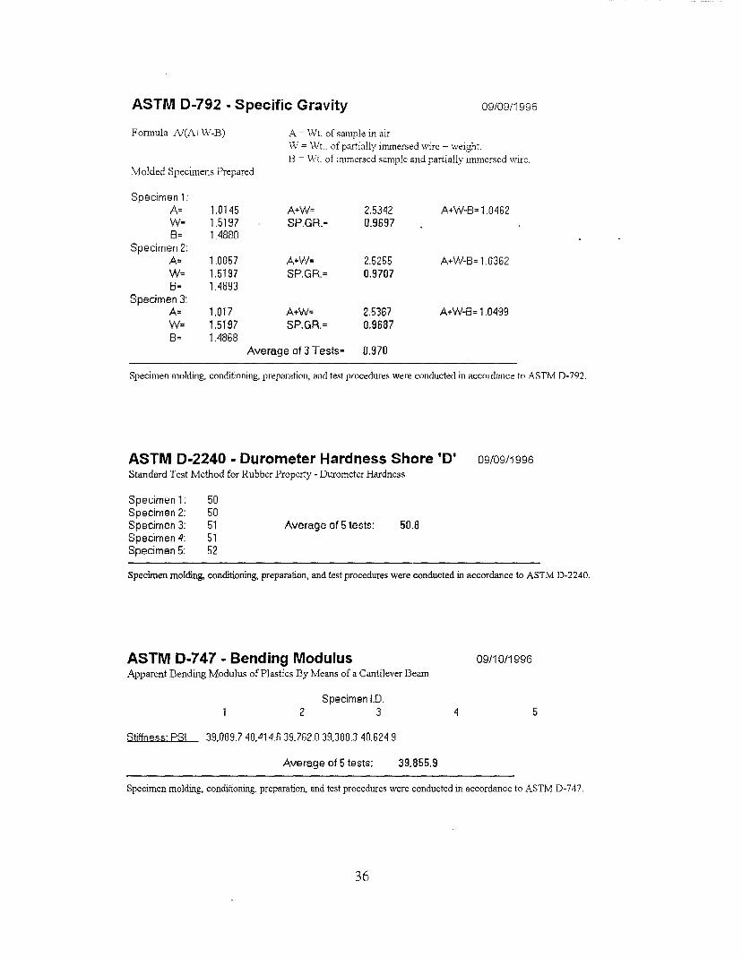
ASTM D-792- Specific Gravity 09/09/1996
Formula A/(A+W-B) A = Wt. of sample in air W = Wt .. of partially immersed wire + weight. B - Wt. of immersed sample and partially Immersed Wire.
Molded Specimens Prepared
Specimen 1: A: 1.0145 A+W= 2.5342 A+W-B= 1.0462 w- 1.5197 SP.GR.• 0.9697 B= 1.4880
Specimen 2: A= 1.0057 A+W: 2.5255 A+W-8= 1.0362 W: 1.5197 SP.GR.: 0.9707 8· 1.4893
Specimen 3: A= 1.017 A+W= 2.5367 A+W-8= 1.0499 W= 1.5197 SP.GR.= 0.9687 8: 1.4868
Avemge of 3 Tests• 0.970
Specimen molding, conditioning, prepamtion, and test procedures were conducted in llccorrhlllce to ASTM D-792.
ASTM D-2240 - Durometer Hardness Shore 'D' Standard Test Method for Rubber Property- Duromctcr Hardness
Specimen 1: Specimen 2: Specimen 3: Specimen 4: Specimen 5:
50 50 51 51 52
Average of 5 tests: 50.8
09/09/1996
Specimen molding, conditioning, preparation, and test procedures were conducted in accordance to ASTM D-2240.
ASTM D-747- Bending Modulus 09/10/1996 Apparent Dending Modulus of Plastics Dy Means of a Cantilever Deam
Specimen 1.0. 2 3 4 5
Stiffness· PSI 39,0897 40,414.6 39)62 0 39.3883 40.624.9
Average of 5 tests: 39,855.9
Specimen molding, conditioning, preparation, and test procedures were conducted in accordance to ASTM D-747.
36

ASTM D-638 - Tensil Properties of Plastics
Specimen 10. 2 3 4 5
Peak PSI 1714 2205 1 ?31 2241 2310 Break PSI 1473 2200 1480 1727 2263 Ultimate Elongation % 585 628 613 603 689 Modulus 50% 1536 1512 1471 1565 1579 Modulus 1 00% 1385 1330 1360 1377 1349 Modulus 200% 13.85 1393 1364 1418 1415
Speed = 5 in/min. Strain Range 500% Stress Renge 0-5000 Coincidence point jews used.
09/10/1996
Average
2040.2 1828.6 623.6 1532.6 1360.2
1395
Specimen molding, conditioning, preparation, and !es( procedures were contludetl in accordance !o ASTM D-638.
ASTM D-790 - Standard Test Method for Flexural! Properties Method 1: Specimen on two supports, & loaded by means of a loading nose at th•~ midway point of the psecimen beam. Procedure 'f.:.
Specimen 10. 2 3 4 5
Flexural (PSI) Yeild- Strength 1271.19 1514.42 1468.62 1460.56 1368.69
Average of 5 Tests: 1416.7 Tongent Mod. of Elasticity (PSI) 8632.89 9180.00 9225.00 9219.08 8897.73
Average of 5 Tests: 9030.94
::lpecirnen molding. conditioning. preparation. and test procedures were conducted in aecordance to A::ITM D-7!.>0.
37

Compression Properties of Rigid Plastucs: 09/10/1996
ASTM D-695 Used as guidance. Loud slowly increased to 200 Lbs. Force,@ crosshead speed of 0.5"/min. 1" Diameter by 112" thick, non-porous, molded specimens. Smface area of block=() 71\S sq. in.
Compressive Deformation Compressive Deformation @ 127.4 PSI @254.8 PSI @ 127.4 PSI
Specimen I.D. (Cm.) (Cm.) (ln.)
L ---.U2.5. ___QJfr _QJ_Q
L ____Q35 _Ml· ____Q_U 1_ _D21 ~ _1W :L _llZB _ll.1l __D.ll
L ---.0.2.:1 __a.n _ill\.8.
Average 0.28 0.36 0 .11
MonsMto T-1 0 lensometer set-up: 2200 Lb. compression load cell with fixtures installed. Crosshead speed= 0.05"/min.; thickness setting= 1; extension= 1 00; Coincidence= 05. Stress setting = 200, 'Y' axis In = 20 Lbs force; strain setting 0.5, 'X' axis In =0.05" dell. Tare first preload to 5 Lbs force. reset tare & standby.
@254.8 PSI (ln.)
___Qj1 ___QjQ _QJj ___illS _QJj
0.14
Specimen molding, conditioning, preparation, and test procedures were conducted in accordance to ASTM D-695. Only cemin section> of the [est procedure in D-695 could be used as a guide and followed. The actual test procedure could not be followed precisely due to U1e specimen size specified, and the limited load cell capacity. Therefore, these compressive lest results are for "in-house" use only, or submi[[ed with this umlen;[anding.
38

REFERENCES
1. H. E. Ross, Jr., D. L. Sicking, R. A. Zimmer, and J. D. Michie, "Recommended Procedures for the Safety Performance Evaluation of Highway Features," NCHRP Report 350, Transportation Research Board, Washington, D.C., 1993.
2. J. D. Michie, "Recommended Procedures for the Safety Performance Evaluation of Highway Appurtenances," NCHRP Report 230, Transportation Research Board, Washington, D.C., 1980.
3. K. K. Mak, R. P. Bligh, and W. L. Menges, "Crash Testing and Evaluation of Existing Guardrail Systems," Volume XI of 14 volume draft final report, FHWA Contract No. DTFH61-89-C-00089, Federal Highway Administration, \Vashington, D. C., December, 1995.
39