TESTING AND COMMISSIONING PROCEDURE FOR … Steam Boilers 4.7 ... Factories and Industrial...
30
TESTING AND COMMISSIONING PROCEDURE FOR STEAM BOILER AND CALORIFIER INSTALLATION IN GOVERNMENT BUILDINGS OF THE HONG KONG SPECIAL ADMINISTRATIVE REGION 2017 EDITION ARCHITECTURAL SERVICES DEPARTMENT THE GOVERNMENT OF THE HONG KONG SPECIAL ADMINISTRATIVE REGION
-
Upload
truonglien -
Category
Documents
-
view
229 -
download
1
Transcript of TESTING AND COMMISSIONING PROCEDURE FOR … Steam Boilers 4.7 ... Factories and Industrial...

TESTING AND COMMISSIONING PROCEDURE
FOR
STEAM BOILER AND CALORIFIER INSTALLATION
IN
GOVERNMENT BUILDINGS
OF
THE HONG KONG SPECIAL ADMINISTRATIVE REGION
2017 EDITION
ARCHITECTURAL SERVICES DEPARTMENT THE GOVERNMENT OF THE HONG KONG SPECIAL ADMINISTRATIVE REGION

PREFACE This Testing and Commissioning (T&C) Procedure aims to lay down the minimum testing and commissioning requirements to be carried out on Steam Boiler and Calorifier Installation in Government Buildings of the Hong Kong Special Administrative Region (HKSAR). Such requirements are applicable to both new installations upon completion and existing ones after major alteration.
The present edition was developed from the 2012 edition by the Mechanical Installation Specialist Support Group that was established under the Building Services Branch Technical Information and Research & Development Committee of the Architectural Services Department (ArchSD). This T&C Procedure has incorporated the latest changes in the 2017 edition of the General Specification for Mechanical Installations.
With the benefit of information technology, electronic version of this T&C Procedure is to be viewed on and free for download from the ArchSD Internet homepage. As part of the Government’s efforts to limit paper consumption, hard copies of this T&C Procedure will not be put up for sale. The ArchSD welcomes comments on this T&C Procedure at any time since the updating of this T&C Procedure is a continuous process to tie in with technological advances.
DISCLAIMER This T&C Procedure is solely compiled for use on Steam Boiler and Calorifier Installation carried out for or on behalf of the ArchSD in Government buildings of the HKSAR. There are no representations, either expressed or implied, as to the suitability of this T&C Procedure for purposes other than that stated above. The material contained in this T&C Procedure may not be pertinent or fully cover the extent of the installation in non-government buildings. Users who choose to adopt this T&C Procedure for their works are responsible for making their own assessments and judgement of all information contained herein. The ArchSD does not accept any liability and responsibility for any special indirect or consequential loss or damage whatsoever arising out of or in connection with the use of this T&C Procedure or reliance placed on it.

Table of Contents Page 1 of 2
SBC_TCP 2017 Edition
TABLE OF CONTENTS Page 1. Introduction 1 2. Objectives of the Testing and Commissioning Works 1 3. Scope of the Testing and Commissioning Works 2-5
3.1 Tests and Inspections during Construction 3.2 Functional Performance Tests 3.3 Statutory Tests and Inspections 3.4 Documentation and Deliverables 3.5 Other Requirements 3.5.1 Testing Equipment Calibration 3.5.2 Registration of Steam Boiler System under the
Ordinance
3.5.3 Approval for the Fuel Oil System and Underground Tank
3.5.4 Approval for the Exhaust & Ventilation System 3.5.5 Examination before putting in use 4. Testing and Commissioning Procedures 5-6
4.1 Factory Manufactured Equipment 4.2 Boiler System 4.3 Water Tanks, Calorifiers and De-aerators 4.4 Steam and Condensate Pipework System 4.5 Hot Water Steam 4.6 Steam Boilers 4.7 Complete Steam Boiler System Annex Annex Page
Annex I Testing and Commissioning Progress Chart for Steam Boiler and Calorifier Installation
1-3
Annex II Testing and Commissioning Certificate for Steam Boiler and
Calorifier Installation 1-15
Part 1 Details of Project Part 2 Declaration Part 3 Items Inspected and Tested
3.1 Pre-commissioning Inspection 3.2 Preparation of Firing 3.3 Performance Tests 3.4 Record of Tests 3.5 Comment

Table of Contents Page 2 of 2
SBC_TCP 2017 Edition
Annex Page
Part 4 Test Record attached to the Test Certificate
4.1 Equipment Details 4.2 Assessing the Thermal Performance of the System
Annex III List of Calibrated Equipment/Instruments Necessary for the Testing and Commissioning Works
1

Page 1 of 6
SBC_TCP 2017 Edition
Testing and Commissioning Procedure for Steam Boiler and Calorifier Installation
1. Introduction
The procedures stated in this Testing and Commissioning (T&C) Procedure cover the activities in preliminary tests and inspections, functional performance tests and the commissioning of newly completed installations and existing ones after major alteration. They are so compiled to facilitate the work of Project Building Services Engineer (PBSE), Project Electrical and Mechanical Engineer (PEME), Project Building Services Inspector (PBSI) and Project Electrical and Mechanical Inspector (PEMI), who are appointed as the Supervising Officer’s Representatives, in the following aspects with respect to testing and commissioning :
(a) To vet and approve the T&C procedures proposed and submitted by the contractor for the Steam Boiler and Calorifier Installation (MI Contractor);
(b) To witness those T&C procedures as specified; and
(c) To accept the T&C certificates and other supporting data.
The MI Contractor shall carry out the T&C works as detailed in this T&C Procedure. Supplementary T&C plans may be proposed by the MI Contractor as appropriate and agreed by PBSE/PEME, e.g. for special equipment supplied and/or installed by the MI Contractor. The administrative requirements for T&C works are in general as specified in the General Specification for Mechanical Installations 2017 Edition and all current corrigenda/amendments thereto published before the date of first tender invitation for the Contract issued by the ArchSD (the General Specification). All words and expressions shall have the meaning as assigned to them under the General Specification unless otherwise specified herein.
2. Objectives of the Testing and Commissioning Works
The objectives of the T&C works are:
(a) To verify proper functioning of the equipment/system after installation;
(b) To verify that the performance of the installed equipment/systems meet with the specified design intent and statutory requirements, if any, through a series of tests and adjustments; and
(c) To capture and record performance data of the whole installation as the baseline for future operation and maintenance.
For the avoidance of doubt, depending on the specific demands of individual installation, the PBSE/PEME may require additional or substitute T&C works in regard to any elements in the Installations other than those indicated in this T&C Procedure.

Page 2 of 6
SBC_TCP 2017 Edition
3. Scope of the Testing and Commissioning Works
3.1 Tests and Inspections during Construction
The purpose of these tests is to ensure that all components and systems are in a satisfactory and safe condition before start up. Preliminary adjustment and setting of equipment at this stage shall also be carried out at the same time to pave way for the coming functional performance tests. Before carrying out any test, the MI Contractor shall ensure that the Installations comply with all relevant statutory requirements and regulations. The T&C works shall also comply with all site safety regulatory requirements currently in force. In particular, the MI Contractor shall note the following:
(a) Electricity Ordinance (Cap. 406), and its subsidiary legislation;
(b) Code of Practice for the Electricity (Wiring) Regulations published by the EMSD;
(c) Occupational Safety and Health Ordinance (Cap. 509), and other subsidiary legislation made under the Ordinance;
(d) Factories and Industrial Undertakings Ordinance (Cap. 59), and other subsidiary legislation, including but not limited to Construction Sites (Safety) Regulations;
(e) Electricity supply rules of the relevant power supply companies;
(f) Boilers and Pressure Vessels Ordinance (Cap. 56), and its subsidiary legislation;
(g) Fire Services Ordinance (Cap.95), and its subsidiary legislation;
(h) Dangerous Goods Ordinance (Cap 295), and its subsidiary legislation;
(i) Gas Safety Ordinance (Cap. 51), and its subsidiary legislation;
(j) Air Pollution Control Ordinance (Cap. 311), and its subsidiary legislation;
(k) Code of Practice for the Prevention of Legionnaires’ Disease published by the EMSD; and
(l) Code of Practice for Owners of Boilers and Pressure Vessels published by Labour Department.
(m) Buildings Energy Efficiency Ordinance (Cap 610).
3.2 Functional Performance Tests The purpose of functional performance tests is to demonstrate that the Installations
can meet the functional and performance requirements as specified in the Specification. Functional performance tests should proceed from the testing of individual components to the testing of different systems in the Installations.
The MI Contractor may have to make temporary modifications as the tests proceed. The specific tests required and the order of tests will vary depending on the type and size of systems, number of systems, sequence of construction, interface with other installations, relationship with the building elements and other specific requirements as indicated in the Specification. The testing of systems may have to be carried out in stages depending on the progress of work or as proposed by the MI Contractor.
Page 3 of 6
SBC_TCP 2017 Edition
Part of the tests may be required to be carried out in suppliers’ premises in accordance with the provisions in the Specification.
Any performance deficiencies revealed during the functional performance tests must be evaluated to determine the cause. After completion of the necessary corrective measures, the MI Contractor shall repeat the tests.
If any test cannot be completed because of circumstances that are beyond the control of the MI Contractor, it shall be properly documented and reported to the PBSE/ PEME, who shall then liaise with the relevant parties to resolve the situation. The MI Contractor shall resume his testing work immediately upon the attainment of a suitable testing environment.
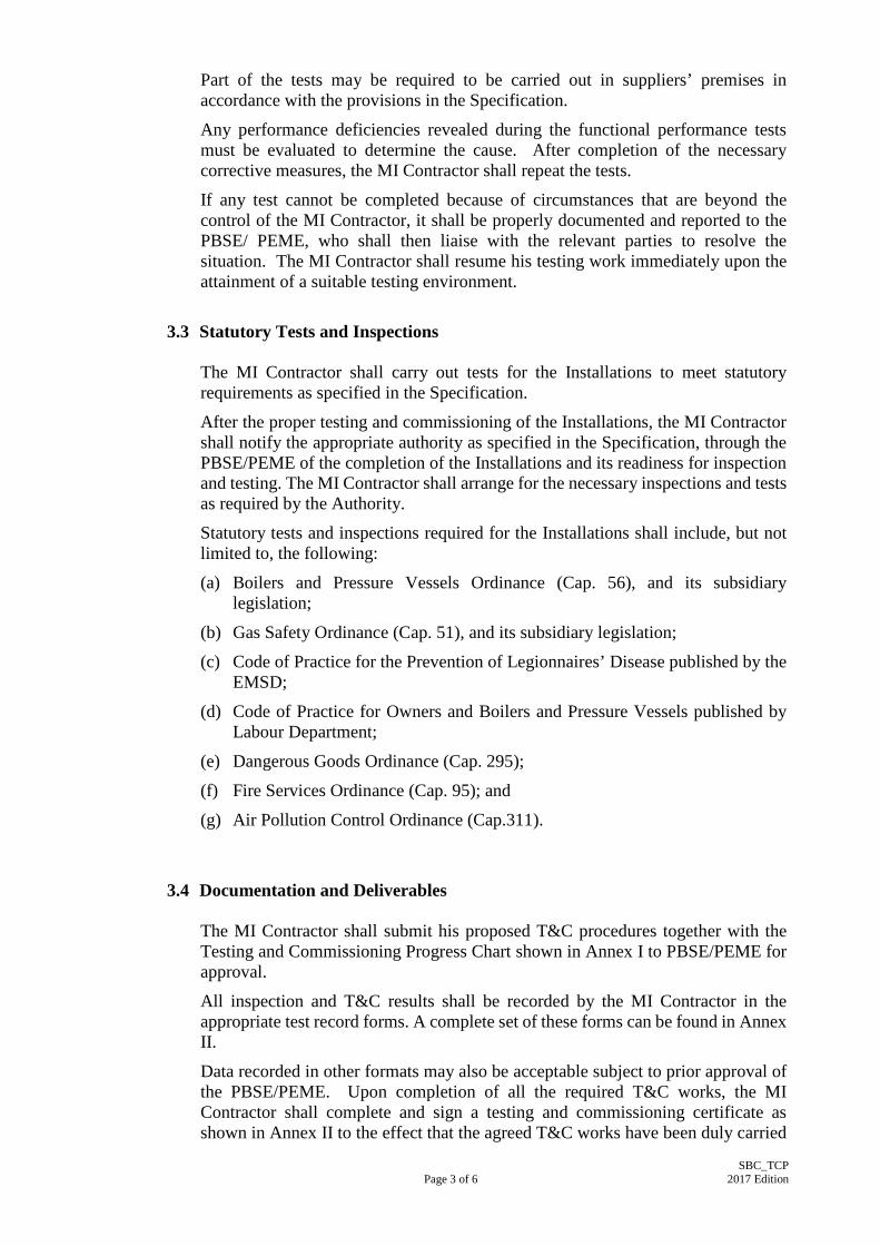
3.3 Statutory Tests and Inspections
The MI Contractor shall carry out tests for the Installations to meet statutory
requirements as specified in the Specification.
After the proper testing and commissioning of the Installations, the MI Contractor shall notify the appropriate authority as specified in the Specification, through the PBSE/PEME of the completion of the Installations and its readiness for inspection and testing. The MI Contractor shall arrange for the necessary inspections and tests as required by the Authority.
Statutory tests and inspections required for the Installations shall include, but not limited to, the following:
(a) Boilers and Pressure Vessels Ordinance (Cap. 56), and its subsidiary legislation;
(b) Gas Safety Ordinance (Cap. 51), and its subsidiary legislation;
(c) Code of Practice for the Prevention of Legionnaires’ Disease published by the EMSD;
(d) Code of Practice for Owners and Boilers and Pressure Vessels published by Labour Department;
(e) Dangerous Goods Ordinance (Cap. 295);
(f) Fire Services Ordinance (Cap. 95); and
(g) Air Pollution Control Ordinance (Cap.311).
3.4 Documentation and Deliverables
The MI Contractor shall submit his proposed T&C procedures together with the Testing and Commissioning Progress Chart shown in Annex I to PBSE/PEME for approval.
All inspection and T&C results shall be recorded by the MI Contractor in the appropriate test record forms. A complete set of these forms can be found in Annex II.
Data recorded in other formats may also be acceptable subject to prior approval of the PBSE/PEME. Upon completion of all the required T&C works, the MI Contractor shall complete and sign a testing and commissioning certificate as shown in Annex II to the effect that the agreed T&C works have been duly carried

Page 4 of 6
SBC_TCP 2017 Edition
out.
A functional performance test report covering all measured data, data sheets, and a comprehensive summary describing the operation of the system at the time of the functional performance tests shall be prepared and submitted to the PBSE/PEME. Deviations in performance from the Specification or the design intent should be recorded, with a description and analysis included.
Where required in the Specification, the MI Contractor shall conduct a final evaluation of the performance of the Installations, the results of which shall be included in the commissioning report.
3.5 Other Requirements
3.5.1 Testing Equipment Calibration
A list of calibrated equipment/instruments necessary for the T&C Works shall be provided as specified in Annex III.
3.5.2 Registration of Steam Boiler System under the Ordinance
The steam boiler equipment including safety valves and accessories after completion shall be subject to the inspection and approval by the Commissioner for Labour and Director of Water Supplies. The examination of the plant by approved independent Surveyor(s) or Laboratories is required if deemed necessary by the above relevant authorities. The MI Contractor is required to obtain the respective Certificates of Approval or Fitness and registration on behalf of the Employer for those equipment or systems which fall within the Boilers & Pressure Vessels Ordinance (Cap.56), and other relevant statutes. One month before the actual commission of the steam boilers and pressure receiver, the equipment should be registered with the Pressure Equipment Division, Labour Department through FORM 3 of the Boiler & Pressure Vessels Ordinance (Cap. 56). In addition, 2 copies of the following documents after endorsement by an Appointed Examiner certifying that they relate to the equipment under application should also be attached for submission:-
(a) The maker's certificate;
(b) Where the boiler or pressure vessel was constructed in Hong Kong a certificate as to the inspection thereof during construction issued by an Approved Examiner; and
(c) Where the boiler or pressure vessel was not constructed in Hong Kong, a certificate issued in respect of the boiler or pressure receiver by a recognised inspecting authority in the country in which it was constructed.
Original Certificates of Approval or Fitness should be framed and posted conspicuously near the respective equipment or systems on the Site. 4 copies of these certificates shall be submitted to the PBSE/PEME.

Page 5 of 6
SBC_TCP 2017 Edition
3.5.3 Approval for the Fuel Oil System and Underground Tank
The MI Contractor shall arrange necessary inspection and approval from
the statutory authorities if fuel oil is used for burner in accordance with the Dangerous Goods Ordinance (Cap. 295) and the Fire Services Ordinance (Cap. 95).
3.5.4 Approval for the Exhaust & Ventilation System
The MI Contractor shall carry out test and request inspection if necessary and obtain approval from the statutory authority regarding the boiler exhaust in accordance with the Air Pollution Control Ordinance (Cap.311).
3.5.5 Examination before putting in use
Before putting in use the equipment under section 18A of the Boilers and
Pressure Vessels Ordinance (Cap. 56), the concerned equipment must be re-examined by an Appointed Examiner to be in safe working order.
4. Testing and Commissioning Procedures
Relevant Clauses In Annex II
4.1 Factory Manufactured Equipment
Factory test shall be carried out for the boiler plant, tanks, cylinders and pumps as required as follows:-
(a) The complete and fully assembled equipment shall be tested at the manufacturer’s works before dispatch, including full operational tests as well as tests on control devices, safety devices and protection devices in accordance with the specification.
NA
(b) Before the tests are carried out, the test procedure shall be submitted to the PBSE/PEME for approval.
NA
(c) The original official Birth Certificate for the equipment shall be submitted to the PBSE/PEME at least 4 calendar weeks before the equipment departs from the manufacturer’s factory and prior to shipment.
NA
4.2 Boiler System Clause 3.1.1 (a) Before securing the access doors and manholes ensure all
components of the system are clean and free from foreign matter.
(b) Mechanical Check shall be carried out on the system to ensure all the components are correctly installed and ready for use.

Page 6 of 6
SBC_TCP 2017 Edition
Relevant Clauses In Annex II
(c) Burner
(i) General connection inspection on supply piping
(ii) Ignition system test
(iii) Safety shut down device functional test, etc.
(d) Fuel Oil System
(i) Fuel supply line condition check
(ii) Pump control function test, etc.
(e) Gas System
(i) Pressure test on piping
(ii) Control test for safety devices, etc.
(f) Underground Tank
(i) Welding standard inspection
(ii) Tank coating inspection
(iii) Hydraulic test
4.3 Water Tanks, Calorifiers and De-aerators Clause 3.1.2
Pre-testing Inspection
4.4 Steam and Condensate Pipework System Clause 3.1.3
Pre-testing Inspection
4.5 Hot Water Steam Clause 3.2.1
(a) Pre-testing Inspection
(b) Water Chemical Test
(c) Water level control test
4.6 Steam Boilers Clause 3.2.2
(a) Pre-testing Inspection
(b) Water Chemical Test
(c) Water level control test
(d) Feed system control test
4.7 Complete Steam Boiler System Clause 3.3
(a) Full-load test
(b) Thermal Test

Annex I
Annex I Page 1 of 3
SBC_TCP 2017 Edition
Testing and Commissioning Progress Chart for Steam Boiler and Calorifier Installation
Contract No.: __________________________________________________________________ Contract Title: _________________________________________________________________ Name of MI Contractor/Sub-contractor: _____________________________________________ Contract Period: __/__/20__ to__/__/20__ *Revised/Actual Completion Date : __/__/20__ dd/mm/yyyy dd/mm/yyyy dd/mm/yyyy
Testing and Commissioning Progress Chart for Steam Boiler and Calorifier Installation (Rev. ) (Note 1)
Dates (Note 2)
Remark
Activities Reference to Annex II
S A S A S A S A S A S A S A S A
1. General Inspection/Tests
3.1.1
Boiler Water storage and
expansion tank
De-aerators Steam and
condensate pipework system
Chimney & flue gas ducting
Blowndown vessel Water treatment
plant
Gas booster & burner
Air inlet Burner Gas supply system Fuel oil system Underground oil
tank
Submission of Record of Test
Annex I
Annex I Page 2 of 3
SBC_TCP 2017 Edition
Testing and Commissioning Progress Chart for Steam Boiler and Calorifier Installation
Testing and Commissioning Progress Chart for Steam Boiler and Calorifier Installation (Rev. ) (Note 1)
Dates (Note 2)
Remark
Activities Reference to Annex II
S A S A S A S A S A S A S A S A
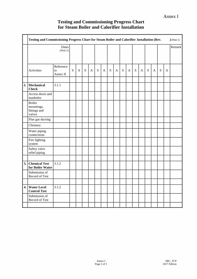
2. Mechanical
Check 3.1.1
Access doors and manholes
Boiler mountings, fittings and valves
Flue gas ducting Chimney Water piping
connections
Fire fighting system
Safety valve relief piping
3. Chemical Test
for Boiler Water 3.1.2
Submission of Record of Test
4. Water Level
Control Test 3.1.2
Submission of Record of Test
Annex I
Annex I Page 3 of 3
SBC_TCP 2017 Edition
Testing and Commissioning Progress Chart for Steam Boiler and Calorifier Installation
Testing and Commissioning Progress Chart for Steam Boiler and Calorifier Installation (Rev. ) (Note 1)
Dates (Note 2)
Remark
Activities Reference to Annex II
S A S A S A S A S A S A S A S A
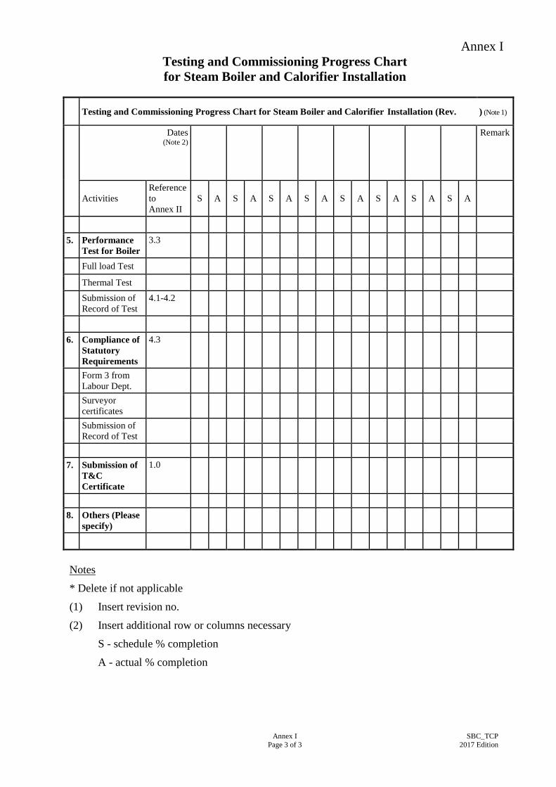
5. Performance
Test for Boiler 3.3
Full load Test Thermal Test
Submission of Record of Test
4.1-4.2
6. Compliance of
Statutory Requirements
4.3
Form 3 from Labour Dept.
Surveyor certificates
Submission of Record of Test
7. Submission of
T&C Certificate
1.0
8. Others (Please
specify)
Notes
* Delete if not applicable
(1) Insert revision no.
(2) Insert additional row or columns necessary
S - schedule % completion
A - actual % completion

Annex II
Annex II Page 1 of 15
SBC_TCP 2017 Edition
Testing and Commissioning Certificate on Steam Boiler and Calorifier Installation
Part 1: Details of Project 1.1 Project title (with location): _________________________________________ 1.2 * P.W.P. / Project No.: _____________________________________________ 1.3 *Contract/Sub-contract/Quotation No.: ________________________________ 1.4 *Contractor/Sub-contractor: _________________________________________ 1.5 Date of Test: _____________________________________________________ 1.6 Name of *PEME/PBSE: ____________________________________________ 1.7 Name of *PBSI/PEMI: _____________________________________________ Part 2: Declaration 2.1 I certify that the Steam Boiler and Calorifier Installation as specified in the
*Contract/Sub-contract/Quotation at the above location has been inspected, tested and commissioned in accordance with this Testing and Commissioning (T&C) Procedure (Note1) and/or any other procedure(s) as agreed between the PEME/PBSE and the MI Contractor. The results are satisfactory in the aspects as mentioned in Part 3 and/or as recorded in Part 4 of this Certificate, except that indicated in the COMMENTS item(s).
2.2 I also certify that site tests have been performed in accordance with the requirements set out in this T&C Procedure and that the results are satisfactory. A record of the tests has been prepared and submitted to the PEME/PBSE.
Name of MI Contractor’s Representative:
_____________________________________
Signature:
__________________________________________
Designation / Post of MI Contractor’s Representative:
_____________________________________
Date signed:
__________________________________________
Name and Stamp of MI Contractor:
_____________________________________
Telephone No.:
__________________________________________
Notes:
1. “T&C Procedure” refers to the Testing and Commissioning Procedure for Steam Boiler and Calorifier Installation.
2. The MI Contractor’s Representative signing this Certificate must be a person or representative authorised by the MI Contractor.
3. Appointed Examiner and Competent Person shall be on site for conducting the T&C.
* Delete as applicable

Annex II
Tested / Checked by : (Name of MI Contractor’s Representative)
Signature - Post :
Tel. No. :
( ) Date :
Witnessed by : (Name(s) of *PBSE/PEME/PBSI/PEMI)
Signature - Post :
Tel. No. :
( ) Date :
Annex II
Page 2 of 15 SBC_TCP
2017 Edition
Part 3:Items Inspected and Tested Item tested/
checked by MI Contractor
Items witnessed by PEME/PBSE/
PBSI/PEMI 3.1 Pre-commissioning Inspection 3.1.1 Boiler
(a) Before securing the access doors and manholes ensure the following items are clean and free from foreign matter.
(i) Boiler interiors, both fireside and waterside (ii) Water storage and/or expansion tank (iii) De-aerators (if installed) (iv) Chimney & flue gas ducting from boiler (v) Blowdown vessel or pits (vi) Water treatment plant (vii) Gas booster (viii) Air inlet to the boiler room (ix) Engrave the registration number allocated on the boiler
in a conspicuous position
(b) Mechanical Check
(i) Access doors and manholes are secured and that joint are tight.
(ii) Boiler mountings, fittings and valves are correctly
installed, with provision for drainage or blowdown and that provision for boiler expansion movement has been made at support or cradles.
(iii) The flue gas ducting is correctly installed, adequately
supported with due provision for expansion and that access covers are secured and fitted with joints.
(iv) The chimneys are complete, with access doors
secured. (v) The piping connections are correctly installed &
blowdown piping, where fitted, is terminated in suitable chambers with drain vents and internal baffles or weirs, and that blowdown chamber covers are secured.
*Yes/No
*Yes/No
*Yes/No
*Yes/No
*Yes/No
*Yes/No
*Yes/No
*Yes/No
*Yes/No
*Yes/No
*Yes/No
*Yes/No
*Yes/No
*Yes/No
*Yes/No
*Yes/No
*Yes/No
*Yes/No
*Yes/No
*Yes/No
*Yes/No
*Yes/No
*Yes/No
*Yes/No
*Yes/No
*Yes/No
*Yes/No
*Yes/No
*Yes/No
*Yes/No

Annex II
Tested / Checked by : (Name of MI Contractor’s Representative)
Signature - Post :
Tel. No. :
( ) Date :
Witnessed by : (Name(s) of *PBSE/PEME/PBSI/PEMI)
Signature - Post :
Tel. No. :
( ) Date :
Annex II
Page 3 of 15 SBC_TCP
2017 Edition
Item tested/ checked by
MI Contractor
Items witnessed by PEME/PBSE/
PBSI/PEMI
(vi) The fire fighting systems are installed and ready for use.
(vii) Safety valve relief piping is sealed, unobstructed and
led to safe position and that the safety valves are free to operate and provided with unrestricted drain connections. Where specified, a works test certificate should be available for the valves. Check other safety devices as appropriate.
(c) Burner
(i) All oil and gas connections are properly made and that
the piping system is complete and that there are no open ends which can discharge fuel into the space or boilers.
(ii) All flame failure, ignition and fuel control devices are
correctly installed. (iii) Control devices, such as safety shut-off valves,
governors, thermostats, pressure-stats, draught regulators, air pressure switches etc. are installed and in good condition.
(iv) Correct filters are installed on oil and gas piping. (iv) Vents terminating at roof level are installed from
safety shut-off systems, meters, over-pressure valves and governors, as specified.
(vi) Emergency isolating valves have been installed
outside the building in safe and accessible positions, on both gas and oil supply lines.
(vii) In the case of rotary cup oil burners, the cups and
forced draught fan impellers spin freely, the cup edges are undamaged and the drive belts, where fitted, are correctly tensioned and aligned.
(viii) In the case of pressure jet burners, the correct nozzles
are fitted, the orifices are undamaged, the primary air fans spin freely, the draught tubes are unobstructed and clean filters are fitted.
*Yes/No
*Yes/No
*Yes/No
*Yes/No
*Yes/No
*Yes/No
*Yes/No
*Yes/No
*Yes/No
*Yes/No
*Yes/No
*Yes/No
*Yes/No
*Yes/No
*Yes/No
*Yes/No
*Yes/No
*Yes/No
*Yes/No
*Yes/No

Annex II
Tested / Checked by : (Name of MI Contractor’s Representative)
Signature - Post :
Tel. No. :
( ) Date :
Witnessed by : (Name(s) of *PBSE/PEME/PBSI/PEMI)
Signature - Post :
Tel. No. :
( ) Date :
Annex II
Page 4 of 15 SBC_TCP
2017 Edition
Item tested/ checked by
MI Contractor
Items witnessed by PEME/PBSE/
PBSI/PEMI (ix) In the case of air atomising burners, the primary and
secondary air supply ducting and silencers are unobstructed and securely connected, the fuel tube slides or flame shape adjustments operate freely and the fan impellers spin freely on their bearings.
(x) In the case of gas burners, nozzles and governor parts
are clean and unobstructed, the nozzle types and adjustments are consistent with the gas supply, the forced draught fans, where fitted, spin freely and the draught tubes are unobstructed. Check that gas pressure proving devices, if provided, are correctly installed.
(d) Diesel Fuel System
(i) The diesel fuel storage tanks have been adequately charged with the correct fuel at the correct storage temperature and the content gauges are operative.
(ii) Electrical supplies are available to pump motors,
heaters and controls. (iii) Valves are open or closed according to the priming
plan. (iv) Drains and piping vents are closed. (v) The system is primed by releasing the vents and drains
until a steady flow is achieved at the correct temperature.
(vi) Ventilation of the tank room is available.
(e) Gas System
(i) Pressure testing of the gas piping has been carried out by the gas supply authority.
(ii) The gas supply is available at the correct pressure and
is of the correct type. (iii) The electrical supply is available to the safety shut-off
controls and the booster, if installed. (iv) The main supply and safety shut-off valves are closed.
*Yes/No
*Yes/No
*Yes/No
*Yes/No
*Yes/No
*Yes/No
*Yes/No
*Yes/No
*Yes/No
*Yes/No
*Yes/No
*Yes/No
*Yes/No
*Yes/No
*Yes/No
*Yes/No
*Yes/No
*Yes/No
*Yes/No
*Yes/No
*Yes/No
*Yes/No
*Yes/No
*Yes/No
Annex II
Tested / Checked by : (Name of MI Contractor’s Representative)
Signature - Post :
Tel. No. :
( ) Date :
Witnessed by : (Name(s) of *PBSE/PEME/PBSI/PEMI)
Signature - Post :
Tel. No. :
( ) Date :
Annex II
Page 5 of 15 SBC_TCP
2017 Edition
Item tested/ checked by
MI Contractor
Items witnessed by PEME/PBSE/
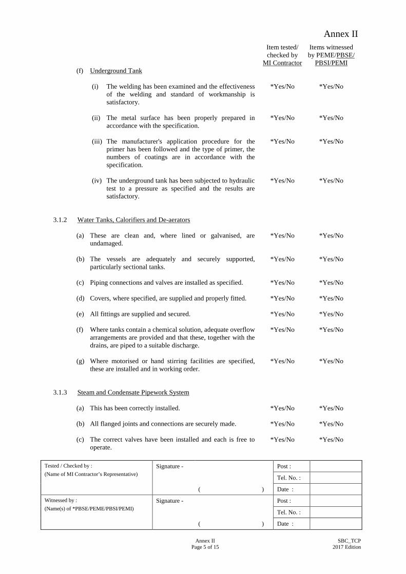
PBSI/PEMI (f) Underground Tank
(i) The welding has been examined and the effectiveness
of the welding and standard of workmanship is satisfactory.
(ii) The metal surface has been properly prepared in
accordance with the specification. (iii) The manufacturer's application procedure for the
primer has been followed and the type of primer, the numbers of coatings are in accordance with the specification.
(iv) The underground tank has been subjected to hydraulic
test to a pressure as specified and the results are satisfactory.
3.1.2 Water Tanks, Calorifiers and De-aerators
(a) These are clean and, where lined or galvanised, are undamaged.
(b) The vessels are adequately and securely supported,
particularly sectional tanks. (c) Piping connections and valves are installed as specified. (d) Covers, where specified, are supplied and properly fitted. (e) All fittings are supplied and secured. (f) Where tanks contain a chemical solution, adequate overflow
arrangements are provided and that these, together with the drains, are piped to a suitable discharge.
(g) Where motorised or hand stirring facilities are specified,
these are installed and in working order. 3.1.3 Steam and Condensate Pipework System
(a) This has been correctly installed. (b) All flanged joints and connections are securely made. (c) The correct valves have been installed and each is free to
operate.
*Yes/No
*Yes/No
*Yes/No
*Yes/No
*Yes/No
*Yes/No
*Yes/No
*Yes/No
*Yes/No
*Yes/No
*Yes/No
*Yes/No
*Yes/No
*Yes/No
*Yes/No
*Yes/No
*Yes/No
*Yes/No
*Yes/No
*Yes/No
*Yes/No
*Yes/No
*Yes/No
*Yes/No
*Yes/No
*Yes/No
*Yes/No
*Yes/No
Annex II
Tested / Checked by : (Name of MI Contractor’s Representative)
Signature - Post :
Tel. No. :
( ) Date :
Witnessed by : (Name(s) of *PBSE/PEME/PBSI/PEMI)
Signature - Post :
Tel. No. :
( ) Date :
Annex II
Page 6 of 15 SBC_TCP
2017 Edition
Item tested/ checked by
MI Contractor
Items witnessed by PEME/PBSE/
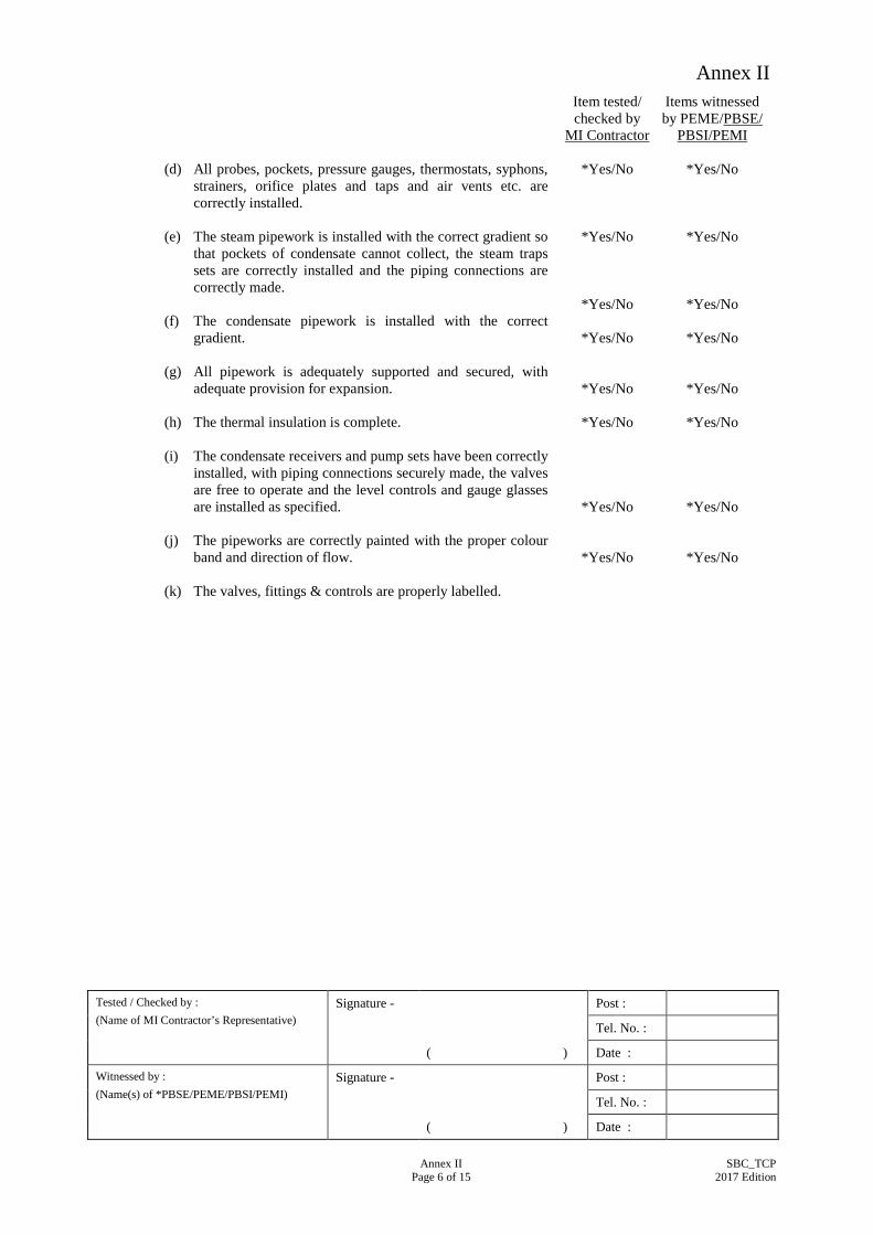
PBSI/PEMI (d) All probes, pockets, pressure gauges, thermostats, syphons,
strainers, orifice plates and taps and air vents etc. are correctly installed.
(e) The steam pipework is installed with the correct gradient so
that pockets of condensate cannot collect, the steam traps sets are correctly installed and the piping connections are correctly made.
(f) The condensate pipework is installed with the correct
gradient. (g) All pipework is adequately supported and secured, with
adequate provision for expansion. (h) The thermal insulation is complete. (i) The condensate receivers and pump sets have been correctly
installed, with piping connections securely made, the valves are free to operate and the level controls and gauge glasses are installed as specified.
(j) The pipeworks are correctly painted with the proper colour
band and direction of flow. (k) The valves, fittings & controls are properly labelled.
*Yes/No
*Yes/No
*Yes/No
*Yes/No
*Yes/No
*Yes/No
*Yes/No
*Yes/No
*Yes/No
*Yes/No
*Yes/No
*Yes/No
*Yes/No
*Yes/No
*Yes/No
*Yes/No

Annex II
Tested / Checked by : (Name of MI Contractor’s Representative)
Signature - Post :
Tel. No. :
( ) Date :
Witnessed by : (Name(s) of *PBSE/PEME/PBSI/PEMI)
Signature - Post :
Tel. No. :
( ) Date :
Annex II
Page 7 of 15 SBC_TCP
2017 Edition
Item tested/ checked by
MI Contractor
Items witnessed by PEME/PBSE/
PBSI/PEMI 3.2 Preparation for Firing 3.2.1 Hot Water Steam
Check
(a) that the system is filled with water to the appropriate level, vented and that the condition of the water is chemically correct.
(b) that the main isolating valves on the distribution headers and
pumps are open and the system has been checked.
3.2.2 Steam Boilers (a) Open the air vent on the boiler shell. (b) Close the main boiler stop valve and the drain valves on the
level and alarm controls. (c) Open the feed check valve and the isolating valves to the
water level controls and the alarm and the feed pump. (d) Check that the blow-down valve is fully closed. (e) Check that electrical supplies are available at the boiler
control panel and that the feed system is available for immediate use.
(f) Check that the condition of the water in the hot-well is
chemically correct and then start the feed pump and fill the boilers to correct gauge glass level. Check also that the direction of rotation of the feed pumps is correct, that the casings are purged of air and that the feed pump motors are not overloaded. Alternatively, fill the boiler from a hose pipe.
(g) Check the operation of the water level control by allowing
the feed pump to run until switched by operation of the level controller. Open the blow-down valve and check that the pump restarts at correct level. Close the blow-down valve.
(h) Check the operation of the high level alarm by isolating the
water level controller and opening its drain valve. The high level alarm should sound when the feed pump has raised the water level to the pre-set condition. Open the isolating valves on the level controller and close its drain valve.
*Yes/No
*Yes/No
*Yes/No
*Yes/No
*Yes/No
*Yes/No
*Yes/No
*Yes/No
*Yes/No
*Yes/No
*Yes/No
*Yes/No
*Yes/No
*Yes/No
*Yes/No
*Yes/No
*Yes/No
*Yes/No
*Yes/No
*Yes/No

Annex II
Tested / Checked by : (Name of MI Contractor’s Representative)
Signature - Post :
Tel. No. :
( ) Date :
Witnessed by : (Name(s) of *PBSE/PEME/PBSI/PEMI)
Signature - Post :
Tel. No. :
( ) Date :
Annex II
Page 8 of 15 SBC_TCP
2017 Edition
Item tested/ checked by
MI Contractor
Items witnessed by PEME/PBSE/
PBSI/PEMI (i) Check the operation of the low level alarm by opening the
blow-down valve. The low level alarm should sound at the correct low water level. Close the blow-down valve and allow the feed pump to restore the water level. Check that the supply of water to the feed tank is adequate. Repeat the sequence and check the operation of the burner lock out at the second low water level.
(j) Check that the water level in the blow-down vessel is
satisfactory and that the vent is adequate.
3.3 Performance Tests 3.3.1 A full-load performance test has been carried out. The results are
satisfactory. 3.3.2 A full-load performance test have NOT been carried out but it
will be carried out during the Maintenance Period. 3.4 Record of Tests A record of test as indicated in Annex II of this T&C Procedure
has been completed and submitted to the project engineer. 3.5 Comment
*Yes/No
*Yes/No
*Yes/No
*Yes/No
*Yes/No
*Yes/No
*Yes/No
*Yes/No

Annex II
Tested / Checked by : (Name of MI Contractor’s Representative)
Signature - Post :
Tel. No. :
( ) Date :
Witnessed by : (Name(s) of *PBSE/PEME/PBSI/PEMI)
Signature - Post :
Tel. No. :
( ) Date :
Annex II
Page 9 of 15 SBC_TCP
2017 Edition
Part 4 : Test Record attached to the Test Certificate 4.1. Equipment Details 4.1.1 Steam Boiler (a) General (i) Manufacturer
(ii) Model
(iii) Rated steam output (kg/hr)
(iv) Rated output pressure (kPa)
(v) Maximum output pressure (kPa)
(vi) Overall dimension L x W x H (mm)
(vii) Diameter of the flue (mm)
(viii) No. of pass (b) Burner (i) Manufacturer
(ii) Type
(iii) Rating (kW)
(iv) Minimum gas supply pressure (kPa)
(v) Gas consumption at rated output (m3/s)
(vi) Minimum oil supply pressure (kPa)
(vii) Oil consumption at rated output (l/s) (c) Feed Pump (i) Type
(ii) Manufacturer
(iii) Flow rate (l/s)
(iv) Pump head (kPa) (d) Accessories (i) Size of safety valves
(ii) Size of steam outlet valves
(iii) Size of blowdown valves
(iv) Size of manholes

Annex II
Tested / Checked by : (Name of MI Contractor’s Representative)
Signature - Post :
Tel. No. :
( ) Date :
Witnessed by : (Name(s) of *PBSE/PEME/PBSI/PEMI)
Signature - Post :
Tel. No. :
( ) Date :
Annex II
Page 10 of 15 SBC_TCP
2017 Edition
(v) Induced draft fan rating (kW)
(vi) Induced draft fan flow rate (m3/s)
(vii) No. of thermometer
(viii) No. of steam pressure gauge (e) Instrumentation Panel Manufacturer/Model No.
(i) Smoke density meter
(ii) Draught gauge
(iii) Carbon dioxide meter
(iv) Flue gas temperature indicator
(v) Steam pressure indicator
(vi) Steam mass flow integrating meter
(vii) Ambient temperature indicator
(viii) Quartz clock (f) Chemical Dosing Equipment (i) Type of chemical used
(ii) Size of the mixing tank
(iii) Material of Construction of the tank
(iv) Make/model of dosing pump
(v) Dosing rate of the pump (l/s)
4.1.2 Calorifier
(a) Manufacturer/Model
(b) Type Hotwater/Steam
(c) Dimension L x W x H (mm)
(d) Storage capacity (L)
(e) Cycle time (min.)
(f) Steam shell working pressure (kPa)
(g) Steam/hotwater consumption (kg/hr or L/hr)
(h) Steam pressure (kPa)
(i) Secondary water flow rate (L/hr)

Annex II
Tested / Checked by : (Name of MI Contractor’s Representative)
Signature - Post :
Tel. No. :
( ) Date :
Witnessed by : (Name(s) of *PBSE/PEME/PBSI/PEMI)
Signature - Post :
Tel. No. :
( ) Date :
Annex II
Page 11 of 15 SBC_TCP
2017 Edition
4.1.3 Diesel Fuel Pump
(a) Manufacturer/Model
(b) Speed
(c) Flowrate (L/hr)
(d) Pump head (kPa)
(e) Flame proof motor & wiring
4.1.4 Level Switch
(a) Manufacturer/Model
(b) Type 4.1.5 Towngas Equipment

Annex II
Tested / Checked by : (Name of MI Contractor’s Representative)
Signature - Post :
Tel. No. :
( ) Date :
Witnessed by : (Name(s) of *PBSE/PEME/PBSI/PEMI)
Signature - Post :
Tel. No. :
( ) Date :
Annex II
Page 12 of 15 SBC_TCP
2017 Edition
4.2. Assessing the Thermal Performance of the System 4.2.1 General Name of Premises : _______________________
Date of Assessment : _______________________ Name of the MI Contractor : _______________________ MI Contractor Representatives : _______________________ Operation & Maintenance Representatives : _______________________ Site Inspector : _______________________
4.2.2 Boiler Data Manufacturer/Make : _______________________
No. of Boilers : _______________________ Type & Description : _______________________ Maximum Rated Steam Output (kg/hr) : _______________________ Working Gauge Pressure (kPa) : _______________________ Final Steam Temperature (oC) : _______________________
4.2.3 Burner Data Burner Manufacturer : _______________________
Type of Burner : _______________________ Thermal Capacity (MJ/Min) : _______________________
4.2.4 Fuel Data Type : _______________________
Calorific Value (gross) : _______________________ Liquid fuel QlF (kJ/kg) : _______________________ Gaseous fuel QgF (MJ/m3) : _______________________
Annex II
Tested / Checked by : (Name of MI Contractor’s Representative)
Signature - Post :
Tel. No. :
( ) Date :
Witnessed by : (Name(s) of *PBSE/PEME/PBSI/PEMI)
Signature - Post :
Tel. No. :
( ) Date :
Annex II
Page 13 of 15 SBC_TCP
2017 Edition
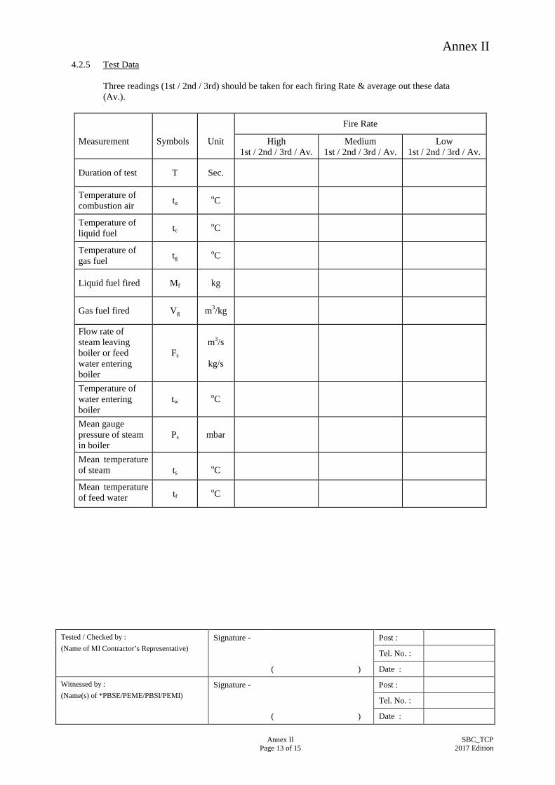
4.2.5 Test Data Three readings (1st / 2nd / 3rd) should be taken for each firing Rate & average out these data (Av.).
Fire Rate
Measurement Symbols Unit High 1st / 2nd / 3rd / Av.
Medium 1st / 2nd / 3rd / Av.
Low 1st / 2nd / 3rd / Av.
Duration of test T Sec.
Temperature of combustion air ta oC
Temperature of liquid fuel tc oC
Temperature of gas fuel tg oC
Liquid fuel fired Mf kg
Gas fuel fired Vg m3/kg
Flow rate of steam leaving boiler or feed water entering boiler
Fs
m3/s
kg/s
Temperature of water entering boiler
tw
oC
Mean gauge pressure of steam in boiler
Ps
mbar
Mean temperature of steam
ts
oC
Mean temperature of feed water tf oC

Annex II
Tested / Checked by : (Name of MI Contractor’s Representative)
Signature - Post :
Tel. No. :
( ) Date :
Witnessed by : (Name(s) of *PBSE/PEME/PBSI/PEMI)
Signature - Post :
Tel. No. :
( ) Date :
Annex II
Page 14 of 15 SBC_TCP
2017 Edition
4.2.6 Calculation
(a) Constant from Steam Table
Measurement Symbols Unit Firing Rate
High Medium Low
Specific volume of saturated steam at the tested temperature & pressure
Vg
m3/kg
Specific volume of saturated liquid at the tested temperature & pressure
Vf
m3/kg
Sensible heat of steam at the pressure of steam discharged from boiler
hf
kJ/kg
Latent heat of steam at pressure of steam discharged from boiler
S
kJ/kg
(b) Rate of Heat Supply by Fuel (i) Liquid Fuel Mf Qlf = —— [ QlF + 1.92 ( tc – ta )] T (ii) Gaseous Fuel Qgf = 1000V QF QgF Vg ( Pa + Pg ) 288 Where V = ————————— 1013 ( tg + 273 ) Pg = Pressure of gaseous fuel at meter in m bar Qlf = Rate of heat supply by liquid fuel Qgf = Rate of supply by gaseous fuel

Annex II
Tested / Checked by : (Name of MI Contractor’s Representative)
Signature - Post :
Tel. No. :
( ) Date :
Witnessed by : (Name(s) of *PBSE/PEME/PBSI/PEMI)
Signature - Post :
Tel. No. :
( ) Date :
Annex II
Page 15 of 15 SBC_TCP
2017 Edition
(c) Heat output from the Steam Boiler QB = Fs ( hf + xS ) – ta C )
Where C = 4.1868 kJ/kg.K for water x = dryness fraction (d) Boiler Efficiency QB EB = —————— x 100% Qlf or Qgf 4.2.7 Result
Measurement Symbols Unit Firing Rate
High Medium Low
Output from boiler QB kW
Boiler Efficiency EB %

Annex III
Annex III Page 1 of 1
SBC_TCP 2017 Edition
List of Calibrated Equipment/Instruments Necessary for the Testing and Commissioning Works
Unless otherwise specified, the equipment/instruments used shall meet the requirements shown in the table below.
Performance Specification Accuracy Maximum period
between calibrations
Tachometer 30-5000 rpm ±1% 1 year
Multi-tester (AVO) 0-1000V 0-10A 0-1MΩ
±1% 1 year
Clamp on ammeter 0-1000A ±1% 1 year
Insulation tester 500V-1000V ±1% 1 year
Pressure Gauge 0-100kPa 0-1000kPa
±2% 1 year
Sound meter 0-120 dBA ±2% 1 year
Hydraulic Tester (suitable range) ±2% 1 year
Temperature Gauge (suitable range) ±2% 1 year
Flow Meter (suitable range) ±2% 1 year
Other necessary testing equipment ±2% 1 year
Notes: Apart from the testing equipment/instruments above, the MI Contractor shall provide additional calibrated equipment/instruments in accordance to the recommendations by the manufacturers to facilitate the inspection, testing and commissioning of the Steam Boiler and Calorifier Installation.