TESTING - JustAnswerww2.justanswer.com/uploads/mr2cycle/2010-12-22_162328_tecumseh… ·...
24
32 .030" (.762 mm) 6-3 6-4 TESTING 1. After repeated efforts to start the engine using the procedure listed in the operator's manual fail, check for spark by removing the high tension lead and removing the spark plug. Install a Tecumseh spark plug tester (part # 670366) and check for spark. If the spark is bright blue and fires every revolution, proceed to step # 2. If no spark, weak spark, or intermittent spark, proceed to step 5. 2. Check the spark plug for cracks in the porcelain, pitted or burned electrodes, excessive carbon build-up and proper air gap setting. Replace if questionable. 3. On TM engines, pull out on compression release and crank the engine over. If engine is not noticeably harder to crank over, replace or clean the compression release mechanism. See Chapter 7 under "Service". 4. Check the air gap between the ignition module and the flywheel magnet. See "Service" in this chapter. 5. Disconnect the ignition grounding lead at the ignition coil and crank the engine over. If spark occurs, check the ignition switch or the electrical wiring for shorting to ground. If no spark, test the ignition module using a coil tester or replace the ignition module. SERVICE AIR GAP SETTING Timing on the solid state module is fixed. The air gap dimension between the laminations of the ignition module and the magnet is .0125" (.317 mm) (use gauge part # 670297) for all TC200 engines, TC300 Type II rotary mower engines and all TM. All other TC300 Type II applications require a .030" (.762 mm) air gap dimension (use gauge part # 670321). Loosen the module mounting bolts, insert the air gap gauge, hold the module against the flywheel magnets and torque the mounting screws to the specification. Remove the gauge and rotate the flywheel to check for any possible striking points. If none are found, the air gap is set correctly (diag. 6-3). NOTE When using the 670321 gauge push the module tight to the flywheel before tightening. SPARK PLUG SERVICE Spark plugs should be removed, cleaned, and gap adjusted periodically. If the porcelain shows cracking, or the electrodes show evidence of pitting, burning, or excessive carbon build- up, replace the spark plug. CAUTION! Do not use a sand blaster to clean spark plugs. Microscopic particles left in the plug can score the engine cylinder during operation. Use solvent and a wire brush to clean the plug and compressed air to blow out completely. Consult your Master Parts Catalog for the correct spark plug and replace if necessary. Set the spark plug gap at .030" (.762 mm) (diag. 6-4). Install the spark plug in the engine and tighten to 230 inch pounds (2.6 Nm) torque. If a torque wrench is not available, screw the spark plug in as far as possible by hand and use a spark plug wrench to turn the spark plug 1/8 to 1/4 of a turn more if using the old plug, and a 1/2 of a turn more if using a new spark plug. NOTE When using the 670321 gauge, push the module tight to the flywheel before tightening. All TC300 Type II non-rotary mower use .030" (.762 mm) Air gap part number 670321 .0125" (.317 mm) part number 670297 All TC200, TC300 Type II rotary mowers and all TM
Transcript of TESTING - JustAnswerww2.justanswer.com/uploads/mr2cycle/2010-12-22_162328_tecumseh… ·...

32
.030"(.762 mm)
6-3
6-4
TESTING
1. After repeated efforts to start the engine using the procedure listed in the operator's manual fail, check for sparkby removing the high tension lead and removing the spark plug. Install a Tecumseh spark plug tester (part #670366) and check for spark. If the spark is bright blue and fires every revolution, proceed to step # 2. If no spark,weak spark, or intermittent spark, proceed to step 5.
2. Check the spark plug for cracks in the porcelain, pitted or burned electrodes, excessive carbon build-up andproper air gap setting. Replace if questionable.
3. On TM engines, pull out on compression release and crank the engine over. If engine is not noticeably harder tocrank over, replace or clean the compression release mechanism. See Chapter 7 under "Service".
4. Check the air gap between the ignition module and the flywheel magnet. See "Service" in this chapter.
5. Disconnect the ignition grounding lead at the ignition coil and crank the engine over. If spark occurs, check theignition switch or the electrical wiring for shorting to ground. If no spark, test the ignition module using a coil testeror replace the ignition module.
SERVICE
AIR GAP SETTING
Timing on the solid state module is fixed. The air gapdimension between the laminations of the ignition moduleand the magnet is .0125" (.317 mm) (use gauge part #670297) for all TC200 engines, TC300 Type II rotary mowerengines and all TM. All other TC300 Type II applicationsrequire a .030" (.762 mm) air gap dimension (use gauge part# 670321). Loosen the module mounting bolts, insert the airgap gauge, hold the module against the flywheel magnetsand torque the mounting screws to the specification. Removethe gauge and rotate the flywheel to check for any possiblestriking points. If none are found, the air gap is set correctly(diag. 6-3).
NOTEWhen using the 670321 gauge push the module tight to the flywheel before tightening.
SPARK PLUG SERVICE
Spark plugs should be removed, cleaned, and gap adjustedperiodically. If the porcelain shows cracking, or the electrodesshow evidence of pitting, burning, or excessive carbon build-up, replace the spark plug. CAUTION! Do not use a sandblaster to clean spark plugs. Microscopic particles left in theplug can score the engine cylinder during operation. Usesolvent and a wire brush to clean the plug and compressedair to blow out completely.
Consult your Master Parts Catalog for the correct spark plugand replace if necessary. Set the spark plug gap at .030"(.762 mm) (diag. 6-4). Install the spark plug in the engine andtighten to 230 inch pounds (2.6 Nm) torque. If a torquewrench is not available, screw the spark plug in as far aspossible by hand and use a spark plug wrench to turn thespark plug 1/8 to 1/4 of a turn more if using the old plug, anda 1/2 of a turn more if using a new spark plug.
NOTEWhen using the 670321 gauge, push the module tight to the flywheel before tightening.
All TC300 Type II non-rotary mower use .030" (.762 mm)
Air gap part number 670321
.0125" (.317 mm)part number 670297
All TC200,TC300 Type II rotary mowers
and all TM

33
CHAPTER 7 INTERNAL ENGINE AND CYLINDER
GENERAL INFORMATIONTC/TM series engines use two cycle operation. Two cycle engines provide a higher horsepower to weight ratio than thesame size four cycle engines. Two cycle engines use two piston strokes for a complete cycle that occurs everycrankshaft revolution, while four cycle engines use four piston strokes and two crankshaft revolutions for a completecycle.
Lubrication is accomplished through oil mixed in the fuel, and the air / fuel / oil mixture flows into the crankcase duringupward piston travel. This mist lubricates all internal bearing surfaces.
OPERATIONA low pressure area is created in the crankcase as thepiston moves upward to compress the air / fuel mixture inthe cylinder. When the piston moves far enough touncover the intake port, the air / fuel mixture from thecarburetor flows into the engine crankcase due to higherpressure atmospheric air. Just before the piston reachestop dead center (TDC), the spark plug ignites the air / fuelmixture in the cylinder.
The expanding combustion gases force the piston down.The downward piston travel causes a pressure build-up inthe crankcase. The piston uncovers the exhaust port firstfollowed by the transfer ports. The exhaust flows out theexhaust port while the pressurized air / fuel mixture entersthe cylinder from the crankcase through the transfer ports.As the piston travels upward the sequence is repeated(diag. 7-1).
MANUAL COMPRESSION RELEASETM engines are equipped with a manual compressionrelease located in the head, near the spark plug. Pushingthe yellow button of the compression release in to the’OPEN’ position lowers the cylinder compression to under100 PSI. Lower compression requires less effort to beused for operation of the rewind starter which allows foreasier starting. As the engine starts the pressure insidethe cylinder builds and automatically "pops" the yellowbutton of the compression release out to the ’CLOSED’position allowing the engine to run at full compression.The yellow compression release button must be pushedin for each pull of the starter rope (diag. 7-2).
Over time, it may be necessary to remove the valveassembly for cleaning. The valve should only be removedwhen the engine is fully cooled. DO NOT TRY TODISASSEMBLE THE VALVE! After removal from theengine, open the valve by depressing the yellow knob andspray with carb & choke cleaner. Allow to soak for 10 to15 minutes and blow compressed air through the valveassembly. Repeat this process if the valve does notoperate freely. Reinstall the valve and tighten to therecommended torque.
1. 2.
3. 4.
7-1
7-2
COMPRESSIONRELEASE

34
1
2
3
4
1. CYLINDER/CRANKCASE2. PISTON RINGS3. CRANKSHAFT ASSEMBLY4. CRANKCASE COVER5. FLYWHEEL SEAL6. PTO SEAL
TYPE TM
7-4
5
6
COMPONENTS
2
31
4
5
1. CYLINDER2. "G" CLIP3. PISTON PIN4. PISTON5. ROD6. CRANKCASE7. CRANKSHAFT8. COVER
8
6
7
TC TYPE I/II
7-3
35
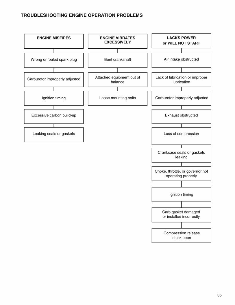
Compression release stuck open
Carb gasket damagedor installed incorrectly
LACKS POWERor WILL NOT START
TROUBLESHOOTING ENGINE OPERATION PROBLEMS
ENGINE MISFIRES ENGINE VIBRATESEXCESSIVELY
Wrong or fouled spark plug
Carburetor improperly adjusted
Ignition timing
Excessive carbon build-up
Leaking seals or gaskets
Bent crankshaft
Attached equipment out ofbalance
Loose mounting bolts Carburetor improperly adjusted
Loss of compression
Crankcase seals or gasketsleaking
Choke, throttle, or governor notoperating properly
Ignition timing
Exhaust obstructed
Air intake obstructed
Lack of lubrication or improperlubrication
36
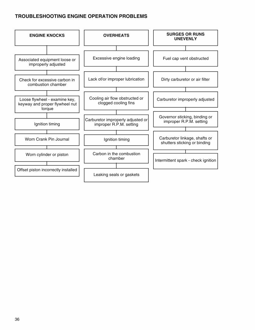
TROUBLESHOOTING ENGINE OPERATION PROBLEMS
ENGINE KNOCKS OVERHEATS SURGES OR RUNS UNEVENLY
Associated equipment loose orimproperly adjusted
Check for excessive carbon in combustion chamber
Loose flywheel - examine key,keyway and proper flywheel nut
torque
Ignition timing
Worn Crank Pin Journal
Worn cylinder or piston
Offset piston incorrectly installed
Excessive engine loading
Lack of/or improper lubrication
Cooling air flow obstructed orclogged cooling fins
Carburetor improperly adjusted orimproper R.P.M. setting
Ignition timing
Carbon in the combustion chamber
Leaking seals or gaskets
Fuel cap vent obstructed
Dirty carburetor or air filter
Carburetor improperly adjusted
Governor sticking, binding or improper R.P.M. setting
Carburetor linkage, shafts or shutters sticking or binding
Intermittent spark - check ignition

37
TESTINGENGINE KNOCKS1. Check the blade hub, adapter, crankshaft coupler or associated equipment for loose fit, or loose bolts. Re-install and
re-torque the bolts to the proper torque.
2. Check the flywheel key and the flywheel and crankshaft keyway for wear or partial shearing. Replace if any damageis evident. Tighten the flywheel nut to the proper torque.
3. Check for the correct ignition module air gap. See Chapter 6 under "Service".
4. Remove the muffler and check for carbon build-up in the combustion chamber and exhaust port. Check the sparkplug for the proper reach and heat range (correct spark plug for the engine). Clean carbon build-up if necessary.
5. Check the internal components (piston, cylinder, and crankshaft journals) for excessive clearance.
ENGINE OVERHEATS1. Make sure the engine is not being overloaded. Remove excess load.
2. Make sure the fuel mixture contains the correct ratio of certified 2-cycle oil to gasoline. Replace the fuel supply ifquestionable.
3. Check for clogged cooling fins or obstructions to the air flow. Remove the rewind assembly, clean and reinstall.
4. Check the engine R.P.M. setting using a Vibratach or other tachometer and compare it to the R.P.M. settings foundon microfiche card # 30 or computer parts lookup according to the engine model and specification number. Adjustas necessary.
5. Remove the muffler and check for carbon build-up in the combustion chamber and exhaust port. Clean asnecessary.
6. Check the carburetor for the correct idle mixture adjustment. Clean the carburetor if the problem persists. SeeChapter 3 under "Service".
7. Check for the correct ignition module air gap. See Chapter 6 under "Service".
8. Inspect the intake gaskets, crankcase seals or gaskets for a leaking condition. Use a commercially availablecrankcase pressure tester and follow the tester's recommended test procedure. See "Disassembly Procedure" inthis chapter for component removal.
SURGES OR RUNS UNEVENLY1. Check the fuel cap to make sure it is venting. Loosen the cap and retry engine operation.
2. Replace or clean the air filter if applicable.
3. Check the carburetor for the correct idle mixture adjustment. Clean the carburetor if the problem persists. SeeChapter 3 under "Service".
4. Check the engine R.P.M. setting using a Vibratach or other tachometer and compare it to the R.P.M. settings foundon microfiche card # 30 or computer parts lookup according to the engine model and specification number. Adjustas necessary.
5. Visually check all linkages. Check the governor spring for a stretched or damaged condition. Check the governorshaft, throttle shaft, and pivot points for binding.
6. Check the ignition module operation using a Tecumseh 670366 Spark Tester inserted in the high tension lead.Check for intermittent spark.
7. Inspect the intake gaskets, crankcase seals or gaskets for a leaking condition. Use a commercially availablecrankcase pressure tester and follow the tester's recommended test procedure. See "Disassembly Procedure" inthis chapter for component removal.
ENGINE MISFIRES1. Check the spark plug for a fouled condition. Replace if questionable.
2. Check the carburetor for the proper adjustments. See "Pre-sets and Adjustments". See Chapter 3 under "Service".
3. Check the air gap dimension. Follow the procedure in Chapter 6 under "Service". Use an in-line spark tester to seeif the problem is ignition related.

38
4. Check the flywheel key for partial shearing.
5. Remove the muffler to check for excessive carbon build-up in the combustion chamber or exhaust port.
6. Inspect the intake gaskets, crankcase seals or gaskets for a leaking condition. Use a commercially availablecrankcase pressure tester and follow the tester's recommended test procedure. See "Disassembly Procedure" inthis chapter for component removal.
ENGINE VIBRATES EXCESSIVELY1. Remove the engine drive and check the attached equipment for an out of balance condition.
2. Check the engine mounting bolts, make sure they are tight.
3. Check the engine crankshaft on the P.T.O. end using a straight edge, square or dial indicator. Blades or adaptersmust be removed. Any deflection will cause a vibration problem.
4. Check the internal engine for bearing roughness or wear, crankshaft bearing journal wear, or a worn cylinder orpiston.
LACKS POWER OR WILL NOT START1. Check the air intake for an obstruction (dirty filter, saturated filter, or other debris).
2. Check the exhaust for a restriction preventing proper exhaust flow.
3. Check the fuel / oil mixture for the gasoline being fresh and the proper amount and kind of oil used. Replace ifquestionable.
4. Visually check the operation of the throttle, air vane governor, and choke (if applicable) for restrictions preventingproper movement.
5. Check the carburetor for the correct idle mixture adjustment. Clean the carburetor if the problem persists. SeeChapter 3 under "Service".
6. Inspect the intake gaskets, crankcase seals or gaskets for a leaking condition. Use a commercially availablecrankcase pressure tester and follow the tester's recommended test procedure. See "Disassembly Procedure" inthis chapter for component removal.
7. Inspect the engine cylinder and ring(s) for a worn condition.
8. Check the flywheel key for partial shearing.
9. Check that the compression release moves outward to the closed position as soon as engine starts.
SERVICE
GENERAL INFORMATIONTC/TM engines do not have oversized pistons available. If the engine bore diameter exceeds the maximum enginespecification and new installed rings exceed the maximum ring end gap, a new short block or engine will be necessary.Engines built with needle bearing P.T.O. main bearings have been upgraded to be serviced with P.T.O. ball bearingreplacements. Gaskets have replaced Loctite sealant between the engine cylinder and the crankcase. Crankcases thatused Loctite sealant between the cylinder cover and the engine crankcase have been upgraded to use an "O" ring in amachined channel. TM engines have been upgraded to include a manual compression release. Engines requiringreplacement of the cylinder, cylinder cover, crankcase, or piston and rod assembly may require the replacement of theshort block or a complete engine. Consult the Tecumseh Master Parts Manual, Microfiche or Electronic Parts Catalogusing the engine model and specification number for replacement part information.
DISASSEMBLY PROCEDURE—TC TYPE I AND TC TYPE II1. Remove the high tension lead boot from the spark plug by twisting and pulling.
2. Remove the spark plug using a 3/4" (19 mm) deep well socket.
3. Drain the fuel from the tank by sliding the fuel line clamp off the carburetor fuel fitting (TC Type I) or fuel tank fitting(TC Type II), twist and pull the fuel line off and drain the fuel into an approved container outdoors and away fromany open flame or combustion source. be sure the engine is cool.
To avoid death or serious injury, DO NOT pour fuel from engine or siphon fuel by mouth.! WARNING
39
7-5
7-6
7-7 7-8
7-9
7-10
Mounting Screws
4. Remove the two hex nuts on the carburetor studs andremove the air cleaner assembly. On TC Type IIengines, remove the two screws on the filter cover,the filter element(s), and then the two hex nuts on thecarburetor studs. If the carburetor stud loosens; tryretightening the hex nuts first, then loosen the nuts.
5. Remove the fuel tank on TC Type I engines byunhooking the tank spring. For TC Type II engines,remove the self-locking nut and washer on the blowerhousing stud and remove the fuel tank.
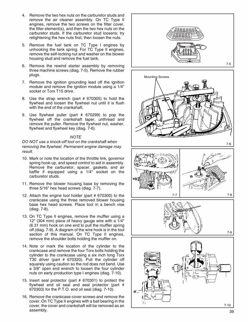
6. Remove the rewind starter assembly by removingthree machine screws (diag. 7-5). Remove the rubberplugs.
7. Remove the ignition grounding lead off the ignitionmodule and remove the ignition module using a 1/4"socket or Torx T15 drive.
8. Use the strap wrench (part # 670305) to hold theflywheel and loosen the flywheel nut until it is flushwith the end of the crankshaft.
9. Use flywheel puller (part # 670299) to pop theflywheel off the crankshaft taper, unthread andremove the puller. Remove the flywheel nut, washer,flywheel and flywheel key (diag. 7-6).
NOTEDO NOT use a knock-off tool on the crankshaft when removing the flywheel. Permanent engine damage may result.
10. Mark or note the location of the throttle link, governorspring hook-up, and speed control to aid in assembly.Remove the carburetor, spacer, gaskets, and airbaffle if equipped using a 1/4" socket on thecarburetor studs.
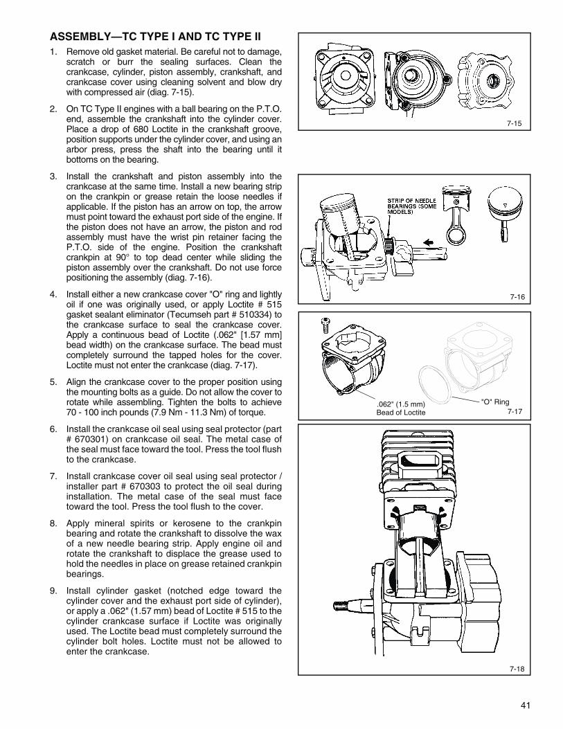
11. Remove the blower housing base by removing thethree 5/16" hex head screws (diag. 7-7).
12. Attach the engine tool holder (part # 670300) to thecrankcase using the three removed blower housingbase hex head screws. Place tool in a bench vise(diag. 7-8).
13. On TC Type II engines, remove the muffler using a12" (304 mm) piece of heavy gauge wire with a 1/4"(6.31 mm) hook on one end to pull the muffler springoff (diag. 7-9). A diagram of the wire hook is in the toolsection of this manual. On TC Type II engines,remove the shoulder bolts holding the muffler on.
14. Note or mark the location of the cylinder to thecrankcase and remove the four Torx bolts holding thecylinder to the crankcase using a six inch long TorxT30 driver (part # 670320). Pull the cylinder offsquarely using caution so the rod does not bend. Usea 3/8" open end wrench to loosen the four cylindernuts on early production type I engines (diag. 7-10).
15. Insert seal protector (part # 670301) to protect theflywheel end oil seal and seal protector (part #670303) for the P.T.O. end oil seal (diag. 7-10).
16. Remove the crankcase cover screws and remove thecover. On TC Type II engines with a ball bearing in thecover, the cover and crankshaft will be removed as anassembly.

40
670304A
17. Turn the crankshaft to the 90° past the top dead center(T.D.C.) position and remove the crankshaft out of thecrankcase opening while sliding the connecting rod offthe crankpin and crankshaft. TC Type II engines use apressed in mechanically retained needle bearing in theconnecting rod. Older TC engines use loose crankpinneedle bearings, make sure to collect all 23 needlebearings. Engines built after Aug. 1995 may also useloose needle bearings (grease retained), 36 needles arerequired (diag. 7-11).
18. Use a bearing splitter and an arbor press to removethe ball bearing and cover assembly from thecrankshaft on TC Type II if necessary.
19. Remove the oil seals by supporting the area aroundthe seal and using a small punch or screwdriver todrive out the seal.
BEARING AND SEAL SERVICE—TC TYPE IAND TC TYPE IIThe crankcase and crankcase cover oil seals can beremoved by prying out or tapping out with a screwdriver.On older TC engines, a retainer ring must be removedwith a pick before the crankcase bearing can be pressedout (diag. 7-12).
Remove the needle bearing by using the bearing installertool (part # 670302) inserted from the outside to drive thebearing out.
To install a new bearing in the engine crankcase, place anew caged needle bearing on the installation tool (part #670302). Use bearing installation tool (part # 670304A) forinstalling the crankcase cover caged needle bearing. Placethe printed side of the bearing toward the installation tool.Lightly oil the outside of the bearing and the crankcasebearing bore. Press the bearing into the crankcase until thetool is flush with the crankcase or cover housing. Insert theretainer ring if applicable (diag. 7-13).
Install a new crankcase oil seal using seal protector /installer (part # 670301). Install the crankcase cover oilseal using seal installer (part # 670303). The metal caseof the seal goes onto the seal protector first. Lightly oil theoutside of the seal. Press the tool and seal in until the toolis flush with the crankcase (diag. 7-14).
Later production TC engines have a step machined in thecrankcase and crankcase cover bearing area. Thischange eliminated the need for a retainer ring. Thebearing and seal installation tools (part # 670302, 670303,670304A) can be used with either style of crankcasecover. The installation tools place the bearing in the coveror the crankcase to the proper depth.
Models equipped with a ball bearing in the crankcasecover can have the ball bearing removed using an arborpress with support placed near the bearing diameter.Press the bearing out of the cover from the outside,pushing the bearing away from the machined step.
A new crankcase cover ball bearing can be installed usingan arbor press. Press the bearing in until the bearing isflush and the bearing contacts the machined step.
Seal protector / installer part # 670303 should be used toinstall a new oil seal in the crankcase cover.
7-11
7-12
7-13
7-14
Needle Bearing Cover
Ball Bearing Cover
670302
670303670301
Retainer Ring
Oil Seal
Bearing
41
7-16
7-17"O" Ring.062" (1.5 mm)
Bead of Loctite
ASSEMBLY—TC TYPE I AND TC TYPE II1. Remove old gasket material. Be careful not to damage,
scratch or burr the sealing surfaces. Clean thecrankcase, cylinder, piston assembly, crankshaft, andcrankcase cover using cleaning solvent and blow drywith compressed air (diag. 7-15).
2. On TC Type II engines with a ball bearing on the P.T.O.end, assemble the crankshaft into the cylinder cover.Place a drop of 680 Loctite in the crankshaft groove,position supports under the cylinder cover, and using anarbor press, press the shaft into the bearing until itbottoms on the bearing.
3. Install the crankshaft and piston assembly into thecrankcase at the same time. Install a new bearing stripon the crankpin or grease retain the loose needles ifapplicable. If the piston has an arrow on top, the arrowmust point toward the exhaust port side of the engine. Ifthe piston does not have an arrow, the piston and rodassembly must have the wrist pin retainer facing theP.T.O. side of the engine. Position the crankshaftcrankpin at 90° to top dead center while sliding thepiston assembly over the crankshaft. Do not use forcepositioning the assembly (diag. 7-16).
4. Install either a new crankcase cover "O" ring and lightlyoil if one was originally used, or apply Loctite # 515gasket sealant eliminator (Tecumseh part # 510334) tothe crankcase surface to seal the crankcase cover.Apply a continuous bead of Loctite (.062" [1.57 mm]bead width) on the crankcase surface. The bead mustcompletely surround the tapped holes for the cover.Loctite must not enter the crankcase (diag. 7-17).
5. Align the crankcase cover to the proper position usingthe mounting bolts as a guide. Do not allow the cover torotate while assembling. Tighten the bolts to achieve70 - 100 inch pounds (7.9 Nm - 11.3 Nm) of torque.
6. Install the crankcase oil seal using seal protector (part# 670301) on crankcase oil seal. The metal case ofthe seal must face toward the tool. Press the tool flushto the crankcase.
7. Install crankcase cover oil seal using seal protector /installer part # 670303 to protect the oil seal duringinstallation. The metal case of the seal must facetoward the tool. Press the tool flush to the cover.
8. Apply mineral spirits or kerosene to the crankpinbearing and rotate the crankshaft to dissolve the waxof a new needle bearing strip. Apply engine oil androtate the crankshaft to displace the grease used tohold the needles in place on grease retained crankpinbearings.
9. Install cylinder gasket (notched edge toward thecylinder cover and the exhaust port side of cylinder),or apply a .062" (1.57 mm) bead of Loctite # 515 to thecylinder crankcase surface if Loctite was originallyused. The Loctite bead must completely surround thecylinder bolt holes. Loctite must not be allowed toenter the crankcase.
7-15
7-18

42
10. Use a piston and rod holder (dimensions are in Chapter9 tool section) to prevent damage to the rod wheninstalling the cylinder. Make sure the ring end gaps arestaggered and the cylinder is in the correct position. Usefingers or ring compressor (part # 670391) (do not alignthe opening in the ring compressor with ring end gaps)to compress the piston rings and push the cylinder ontothe piston. Remove ring compressor by sliding openingof tool past the connecting rod. Do not rotate or twist thecylinder (diag. 7-18).
11. Install Torx bolts and alternately torque the bolts to80-95 inch pounds (9.04 Nm - 10.7 Nm), or onengines with studs instead of bolts: push the cylinderdown to a depth where the nuts can be started on thestuds. Finger tighten the nuts, use a wrench to snug,and torque the nuts to 70 - 100 inch pounds (7.9 Nm- 11.3 Nm) using a crowfoot on the torque wrench.
12. Install the exhaust gasket, muffler, spark arrestor ifapplicable, bolts or muffler springs. Torque the mufflerbolts to 85 - 105 inch pounds (9.6 Nm - 11.8 Nm) oftorque if applicable. The longer ends of the springshook into the bosses on the cylinder. Use heavygauge wire (as shown in the tool section) to stretchand hook the muffler springs (diag. 7-19). Install themuffler heat shield if applicable. Remove the engineholder.
13. Attach the blower housing base using the threescrews removed from the engine holder and torquethe screws to 30-40 inch pounds (3.3 Nm - 4.5 Nm).
14. On TC Type I models, install the governor air vaneassembly into the blower housing base as shown.Some models use a spring clip to hold the air vane inposition. Insert and tighten the speed adjusting leverhold-down screw to the blower housing base. Hookthe long end of the governor spring into the notch onthe neck of the air vane. The short end hooks into thehole in the speed adjusting lever as shown (diag. 7-20).
15. Insert one end of the throttle link in the hole in the airvane and the other end in the hole closest to thethrottle shaft. Install the air baffle (if equipped),gaskets, spacer, and carburetor. (See CarburetorAssembly instructions on page 22, Chapter 3.)Assemble gaskets correctly, do not plug the pulsepassage. Torque the bolts to 30-40 inch pounds(3.3 Nm - 4.5 Nm). On TC Type II models, attach andtorque the air vane to the carburetor throttle shaftbefore installation. Hook the long end of the governorspring in the hole in the air vane and the short end inthe hole in the speed control bracket. The springhooks from beneath both components. Use theillustration (diag. 7-21) and the following springlocation chart if the air vane has more than onegovernor spring hole and uses a colored spring with asquare and round end.
SPRING COLOR SPRING POSITION
Orange or Green 1
Pink, Red, or Black 2
7-19
7-20
7-21
Spring Position 2Spring Position 1

43
Air Cleaner Housing
16. Install the flywheel key and flywheel. Install theflywheel washer and nut, use a strapwrench (part #670305) to hold the flywheel, and torque the nut to15-20 foot pounds (1.6 Nm - 2.2 Nm).
17. Attach the ignition module, use the proper air gapgauge between the flywheel magnets and the modulelaminations (use .0125" (.317 mm) gauge part #670297 for all TC200 Type I engines, TC300 Type IIrotary mower engines and all TM. All other TC300Type II applications require a .030" (.762 mm) air gapdimension (use gauge part # 670321). Torque themodule mounting screws to 30-40 inch pounds(3.3 Nm - 4.5 Nm). Remove the air gap gauge, rotatethe flywheel to assure it does not strike the ignitionmodule. Attach ignition grounding lead to the moduleterminal (diag. 7-22).
NOTEWhen using .030" (.762 mm) air gap gauge, it is critical to push the module against the flywheel magnet before tightening the mounting screw.
18. Install the blower housing and rewind assembly.Replace the debris guard if applicable.
19. Connect the fuel line at the carburetor, position thefuel line clamp on the fuel fitting, and attach the fueltank to the engine using the mounting spring. On TCType II engines, hook the upper fuel tank mountingtab over the blower housing stud and the carburetorstuds. Make sure the "O" ring is in position betweenthe fuel tank and the carburetor. Tighten the retainingnuts, install filter(s), and attach the air cleaner cover.
20. Reset the governor and/or speed control using theprocedure in Chapter 4 under "Service".
21. Install the spark plug and connect the high tensionlead.
DISASSEMBLY PROCEDURE—TM1. Remove the high tension lead boot from the spark
plug by twisting and pulling.
2. Remove the spark plug using a 3/4" (19 mm) deepwell socket.
3. Drain the fuel from the tank by sliding the fuel lineclamp off the fuel tank fitting, twist and pull the fuelline off and drain the fuel into an approved containeroutdoors and away from any open flame orcombustion source. Be sure engine is cool.
To avoid death or serious injury,DO NOT pour fuel from engine or
siphon fuel by mouth.
4. Remove the two screws on the filter cover, the filterelement(s), and then the two hex nuts and spacers, ifequipped on the carburetor studs (diag. 7-23).
5. Remove the self-locking nut and washer on theblower housing stud and remove the fuel tank.
! WARNING
.0125" (.317 mm)part number 670297
All TC200, TC300 Type II rotary mowers and all TM
All TC300 Type II non-rotary mower use .030" (.762 mm) Air gap part number 670321
Poly Air-Cleaner
Flocked Screen
Air Cleaner Cover
Cover Screw
Fuel Tank
7-23
7-22

44
Torx Head Bolt
7-25
6. Remove the rewind starter assembly by removingthree machine screws (diag. 7-24).
7. Remove the ignition grounding lead off the ignitionmodule and remove the ignition module using a 1/4"socket or Torx T15 drive.
8. Use the strap wrench (part # 670305) to hold theflywheel and loosen the flywheel nut until it is flushwith the end of the crankshaft.
9. Use flywheel puller (part # 670299) to pop theflywheel off the crankshaft taper, unthread andremove the puller. Remove the flywheel nut, washer,flywheel and flywheel key (diag. 7-25).
NOTEDo not use a knock-off tool on the crankshaft when removing the flywheel. Permanent engine damage may result.
10. Mark or note the location of the throttle link, governorspring hook-up, and speed control to aid in assembly.Remove the carburetor, spacer, gaskets, and airbaffle if equipped.
11. Remove the blower housing base by removing thethree 5/16" hex head screws and if equipped, the two1/4" hex head screws for the muffler heat shield.
12. Place engine in a soft-jawed bench vise.
NOTEDO NOT over tighten engine in vise. Permanent engine damage may result.
13. Remove the two shoulder bolts holding the mufflerand remove the muffler.
14. Remove the compression release valve using a 1/2"deep socket.
15. Remove the four Torx bolts holding the crankcasehalves together using a Torx T30 driver(part # 670320). Remove the crankcase cover (diag.7-26).
16. Pull the crankshaft, piston and rod assembly squarelyout of the cylinder using caution so the rod does notbend (diag. 7-27).
17. Remove both oil seals from the crankshaft.
BEARING AND SEAL SERVICE—TMThe crankshaft bearings can only be replaced as part ofthe crankshaft, piston and rod assembly. Follow the"Disassembly" and "Assembly" procedures for TMengines.
The crankshaft oil seals can be replaced by separatingthe crankcase and cover. Follow the "Disassembly" and"Assembly" procedures for TM engines.
7-24
7-26
7-27
45
Seals
7-30
ASSEMBLY—TM1. Remove old gasket material. Be careful not to damage,
scratch or burr the sealing surfaces. Clean thecrankcase, cylinder, piston assembly, crankshaft, andcrankcase cover using cleaning solvent and blow drywith compressed air.
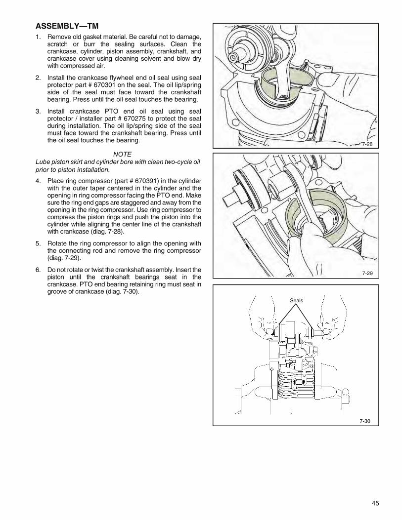
2. Install the crankcase flywheel end oil seal using sealprotector part # 670301 on the seal. The oil lip/springside of the seal must face toward the crankshaftbearing. Press until the oil seal touches the bearing.
3. Install crankcase PTO end oil seal using sealprotector / installer part # 670275 to protect the sealduring installation. The oil lip/spring side of the sealmust face toward the crankshaft bearing. Press untilthe oil seal touches the bearing.
NOTELube piston skirt and cylinder bore with clean two-cycle oil prior to piston installation.
4. Place ring compressor (part # 670391) in the cylinderwith the outer taper centered in the cylinder and theopening in ring compressor facing the PTO end. Makesure the ring end gaps are staggered and away from theopening in the ring compressor. Use ring compressor tocompress the piston rings and push the piston into thecylinder while aligning the center line of the crankshaftwith crankcase (diag. 7-28).
5. Rotate the ring compressor to align the opening withthe connecting rod and remove the ring compressor(diag. 7-29).
6. Do not rotate or twist the crankshaft assembly. Insert thepiston until the crankshaft bearings seat in thecrankcase. PTO end bearing retaining ring must seat ingroove of crankcase (diag. 7-30).
7-28
7-29

46
Torx Head Bolt
7-32
7. Clean both gasket surfaces using isopropyl alcoholbefore application of the gasket eliminator.
8. Apply Loctite #515 gasket sealant eliminator (Tecumsehpart #510334) to the crankcase surface to seal thecrankcase cover. Apply a continuous bead of Loctite(.062" [1.57 mm] bead width) on the crankcase surfaceaccording to the pattern. Loctite must not enter thecrankcase (diag. 7-31).
9. Align the crankcase cover to the proper position usingthe mounting bolts as a guide. Once cover screws aresnug, tap cover down using a soft mallet to helpdisplace the gasket eliminator. Torque cover screwsto recommended torque specifications. Tighten thebolts to achieve 105 inch pounds (11.8 Nm) of torque(diag. 7-32).
10. Install the compression release. Torque to 100 inchpounds (11.3 Nm).
11. Install the exhaust gasket, muffler, spark arrestor ifapplicable, and bolts. Torque the muffler bolts to110 inch pounds (12.4 Nm).
12. Attach the blower housing base using three screwsand torque the screws to 30-40 inch pounds (3.3 Nm- 4.5 Nm).
13. Attach and torque the air vane to the carburetorthrottle shaft before installation.
14. On early TM engines, install the air baffle, gaskets,spacer, and carburetor. Assemble gaskets correctly,do not block the pulse passage. Torque the two hexnuts to 30-40 inch pounds (3.3 Nm - 4.5 Nm). (SeeCarburetor Assembly instructions on page 22,Chapter 3.)
15. On later TM engines, install long carburetor screwsthrough the back of the spacer. Ensure that hexheads of the screw are properly seated in the spacer.Install the air baffle, gaskets and spacer on theengine. Install gaskets correctly, do not block thepulse passage. Torque the two hex screws to 30-40inch pounds (3.3 Nm - 4.5 Nm).
16. Install the flywheel key and flywheel. Install theflywheel washer and nut, use a strapwrench (part#670305) to hold the flywheel, and torque the nut to15-20 foot pounds (1.6 Nm - 2.2 Nm).
Go to next page.
7-31
47
.0125" (.317 mm)part number 670297
All TC200,TC300 Type II rotary mowers and all TM
All TC300 Type II non-rotary mower use .030" (.762 mm) Air gap part number 670321
7-33
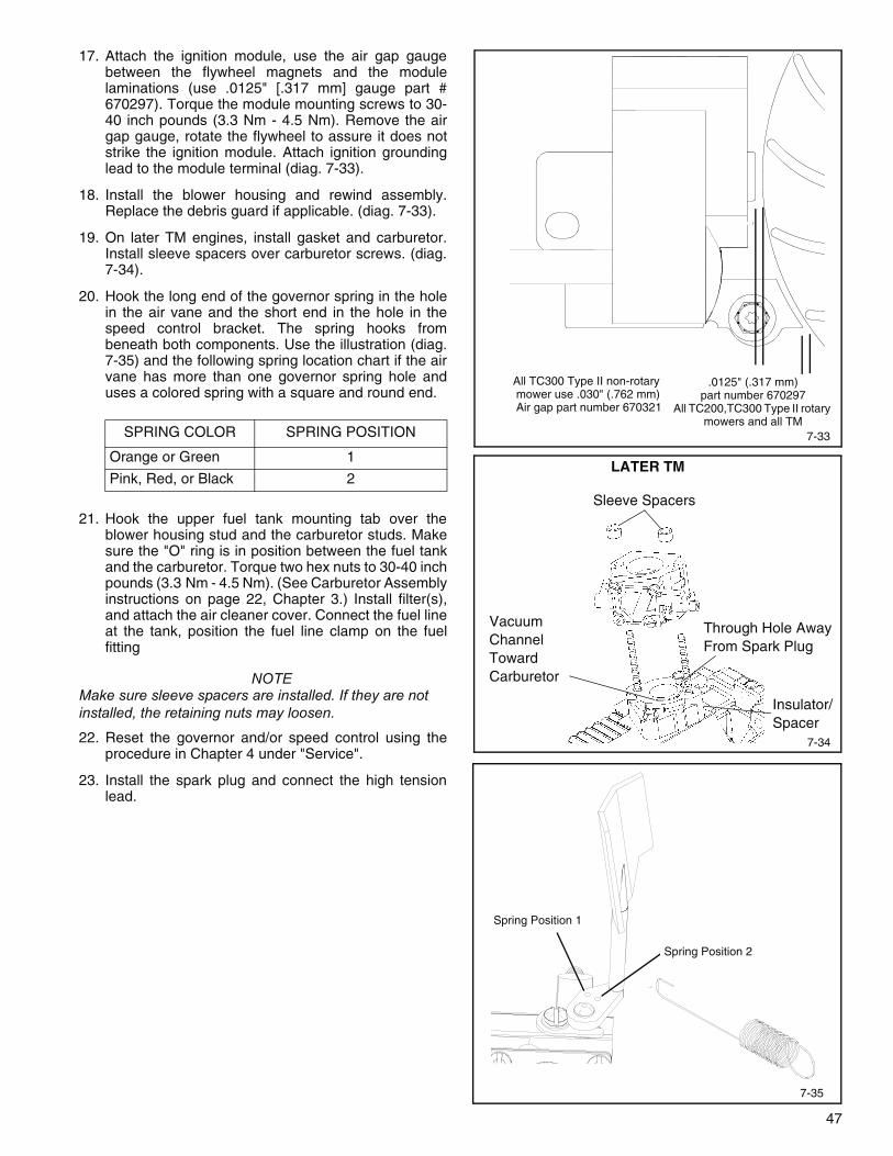
17. Attach the ignition module, use the air gap gaugebetween the flywheel magnets and the modulelaminations (use .0125" [.317 mm] gauge part #670297). Torque the module mounting screws to 30-40 inch pounds (3.3 Nm - 4.5 Nm). Remove the airgap gauge, rotate the flywheel to assure it does notstrike the ignition module. Attach ignition groundinglead to the module terminal (diag. 7-33).
18. Install the blower housing and rewind assembly.Replace the debris guard if applicable. (diag. 7-33).
19. On later TM engines, install gasket and carburetor.Install sleeve spacers over carburetor screws. (diag.7-34).
20. Hook the long end of the governor spring in the holein the air vane and the short end in the hole in thespeed control bracket. The spring hooks frombeneath both components. Use the illustration (diag.7-35) and the following spring location chart if the airvane has more than one governor spring hole anduses a colored spring with a square and round end.
21. Hook the upper fuel tank mounting tab over theblower housing stud and the carburetor studs. Makesure the "O" ring is in position between the fuel tankand the carburetor. Torque two hex nuts to 30-40 inchpounds (3.3 Nm - 4.5 Nm). (See Carburetor Assemblyinstructions on page 22, Chapter 3.) Install filter(s),and attach the air cleaner cover. Connect the fuel lineat the tank, position the fuel line clamp on the fuelfitting
NOTEMake sure sleeve spacers are installed. If they are not installed, the retaining nuts may loosen.
22. Reset the governor and/or speed control using theprocedure in Chapter 4 under "Service".
23. Install the spark plug and connect the high tensionlead.
SPRING COLOR SPRING POSITION
Orange or Green 1
Pink, Red, or Black 2
7-34
Sleeve Spacers
Through Hole Away From Spark Plug
Vacuum Channel Toward Carburetor
LATER TM
Spring Position 2
7-35
Insulator/Spacer
Spring Position 1
48
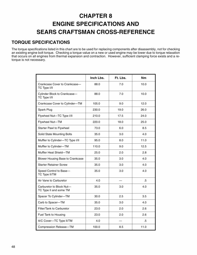
TORQUE SPECIFICATIONSThe torque specifications listed in this chart are to be used for replacing components after disassembly, not for checkingan existing engine bolt torque. Checking a torque value on a new or used engine may be lower due to torque relaxationthat occurs on all engines from thermal expansion and contraction. However, sufficient clamping force exists and a re-torque is not necessary.
Inch Lbs. Ft. Lbs. Nm
Crankcase Cover to Crankcase— TC Type I/II
88.0 7.0 10.0
Cylinder Block to Crankcase—TC Type I/II
88.0 7.0 10.0
Crankcase Cover to Cylinder—TM 105.0 9.0 12.0
Spark Plug 230.0 19.0 26.0
Flywheel Nut—TC Type I/II 210.0 17.5 24.0
Flywheel Nut—TM 220.0 18.0 25.0
Starter Pawl to Flywheel 73.0 6.0 8.5
Solid State Mounting Bolts 35.0 3.0 4.0
Muffler to Cylinder—TC Type I/II 95.0 8.0 11.0
Muffler to Cylinder—TM 110.0 9.0 12.5
Muffler Heat Shield—TM 25.0 2.0 2.8
Blower Housing Base to Crankcase 35.0 3.0 4.0
Starter Retainer Screw 35.0 3.0 4.0
Speed Control to Base—TC Type II/TM
35.0 3.0 4.0
Air Vane to Carburetor 4.0 — .5
Carburetor to Block Nut—TC Type II and some TM
35.0 3.0 4.0
Spacer To Cylinder—TM 30.0 2.5 3.5
Carb to Spacer—TM 35.0 3.0 4.0
Filter/Tank to Carburetor 23.0 2.0 2.6
Fuel Tank to Housing 23.0 2.0 2.6
A/C Cover—TC Type II/TM 4.0 — .5
Compression Release—TM 100.0 8.5 11.0
CHAPTER 8 ENGINE SPECIFICATIONS AND
SEARS CRAFTSMAN CROSS-REFERENCE

49
ENGINE SPECIFICATIONS
All Dimensions are in inches TC200 TC300 Type II TM
US Metricmm
US Metricmm
US Metricmm
HP (Approx.) 1.6 1.19 Kw 2.0 1.49 Kw 2.0 1.49 Kw
Bore 1.43701.4380
36.4936.52
1.74951.7505
44.4344.46
1.74951.7505
44.4344.46
Stroke 1.25 31.7 1.25 31.7 1.25 31.7
Displacement (in2) (cc)
2.0 32.78 cc 3.0 49.17 cc 3.0 49.17 cc
Spark Plug Gap
.030 .762 .030 .762 .030 .762
Ignition Mod-ule Air Gap
.0125 .317 .030Note (A)
.762 .0125 .317
Piston Ring End Gap
.004
.014.101.355
.005
.015.127.381
.005
.015.127.381
Piston Diame-ter
1.43301.4345
36.39836.436
1.74501.7465
44.30344.361
1.74501.7465
44.30344.361
Piston Ring Groove WidthTop/Bottom
.0485
.04951.2311.257
.0485
.04951.23191.2573
.0485
.04951.23191.2573
Piston Ring Width
.046
.0471.1681.193
.046
.0471.16841.1938
.046
.0471.16841.1938
Crankpin Jour-nalDiameter
.5985
.5990Note (B)
15.20115.214
.5985
.5990Note (B)
15.20115.214
N/A N/A
Main Bearing DiameterP.T.O. Side
.6248
.6253Note (C)
15.86915.882
.6248
.6253Note (C)
15.86915.882
N/A N/A
Main Bearing DiameterFlywheel
.4993
.500312.68212.702
.4993
.500312.68212.707
N/A N/A
CrankshaftEnd Play
.004
.012Note (D)
.1016.305
.004
.012Note (D)
.1016.305
N/A N/A
Note (A) - TC300 rotary mower applications use .0125" (.317 mm) air gap.Note (B) - Mechanically retained needle bearings use .6850/.6855 (17.399 mm / 17.411 mm)or .6870/.6875 (17.449 mm / 17.462 mm)Note (C) - Check to determine bearing diameters .7498/.7503 (19.044 mm / 19.057 mm),.6695/.6699 (17.005 mm / 17.015 mm), .5898/.5903 (14.980 mm / 14.993 mm)Note (D) - Engine with P.T.O. ball bearings no end play.
50
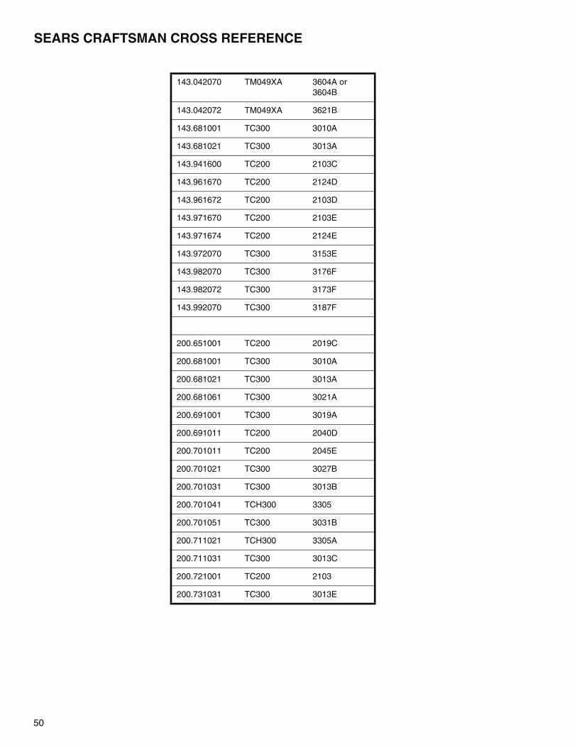
SEARS CRAFTSMAN CROSS REFERENCE
143.042070 TM049XA 3604A or 3604B
143.042072 TM049XA 3621B
143.681001 TC300 3010A
143.681021 TC300 3013A
143.941600 TC200 2103C
143.961670 TC200 2124D
143.961672 TC200 2103D
143.971670 TC200 2103E
143.971674 TC200 2124E
143.972070 TC300 3153E
143.982070 TC300 3176F
143.982072 TC300 3173F
143.992070 TC300 3187F
200.651001 TC200 2019C
200.681001 TC300 3010A
200.681021 TC300 3013A
200.681061 TC300 3021A
200.691001 TC300 3019A
200.691011 TC200 2040D
200.701011 TC200 2045E
200.701021 TC300 3027B
200.701031 TC300 3013B
200.701041 TCH300 3305
200.701051 TC300 3031B
200.711021 TCH300 3305A
200.711031 TC300 3013C
200.721001 TC200 2103
200.731031 TC300 3013E
51
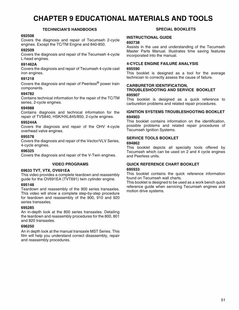
CHAPTER 9 EDUCATIONAL MATERIALS AND TOOLSTECHNICIAN'S HANDBOOKS
692508 Covers the diagnosis and repair of Tecumseh 2-cycleengines. Except the TC/TM Engine and 840-850.
692509 Covers the diagnosis and repair of the Tecumseh 4-cycleL-head engines.
691462A Covers the diagnosis and repair of Tecumseh 4-cycle castiron engines.
691218Covers the diagnosis and repair of Peerless® power traincomponents.
694782Contains technical information for the repair of the TC/TMseries, 2-cycle engines.
694988Contains diagnosis and technical information for therepair of TVS840, HSK/HXL845/850, 2-cycle engines.
695244ACovers the diagnosis and repair of the OHV 4-cycleoverhead valve engines.
695578Covers the diagnosis and repair of the Vector/VLV Series,4-cycle engines.
696325Covers the diagnosis and repair of the V-Twin engines.
VIDEO PROGRAMS
69633 TVT, VTX, OV691EAThis video provides a complete teardown and reassemblyguide for the OV691EA (TVT691) twin cylinder engine.
695148Teardown and reassembly of the 900 series transaxles.This video will show a complete step-by-step procedurefor teardown and reassembly of the 900, 910 and 920series transaxles.
695285An in-depth look at the 800 series transaxles. Detailingthe teardown and reassembly procedures for the 800, 801and 820 transaxles.
696250An in depth look at the manual transaxle MST Series. Thisfilm will help you understand correct disassembly, repairand reassembly procedures.
SPECIAL BOOKLETS
INSTRUCTIONAL GUIDE692738Assists in the use and understanding of the TecumsehMaster Parts Manual. Illustrates time saving featuresincorporated into the manual.
4-CYCLE ENGINE FAILURE ANALYSIS695590This booklet is designed as a tool for the averagetechnician to correctly assess the cause of failure.
CARBURETOR IDENTIFICATION, TROUBLESHOOTING AND SERVICE BOOKLET695907This booklet is designed as a quick reference tocarburetion problems and related repair procedures.
IGNITION SYSTEMS TROUBLESHOOTING BOOKLET694903This booklet contains information on the identification,possible problems and related repair procedures ofTecumseh Ignition Systems.
SERVICE TOOLS BOOKLET694862This booklet depicts all specialty tools offered byTecumseh which can be used on 2 and 4 cycle enginesand Peerless units.
QUICK REFERENCE CHART BOOKLET695933This booklet contains the quick reference informationfound on Tecumseh wall charts.This booklet is designed to be used as a work bench quickreference guide when servicing Tecumseh engines andmotion drive systems.

52
FLYWHEEL PULLER 670299
STRAP WRENCH 670305
HEAVY GAUGE WIRE HOOK FOR REMOVING MUFFLER SPRINGS
PISTON AND ROD HOLDER
A piece of 3/8" (9.5 mm) wood, 1-1/2" (38.1 mm) wide by 4" (101 mm) long with a slot 3/8" (9.5 mm) wide by 2" (50 mm) long cut out of the center will hold the piston and rod.
SPARK TESTER 670366
RING COMPRESSOR 670391
12" LONG
(309 mm)
1/4"
(6.35 mm)
TOOLS

53
ENGINE HOLDER 670300
To assist in reassembly of the engine block and its compo-nents an Engine Holder, part # 670300, has been devel-oped. Attach to the crankcase of the engine with the blower housing base screws and insert the other end into a bench vise to hold crankcase while inserting engine components. Use on TC200 Type I and TC300 Type II engines.
AIR GAP GAUGE 670297
Used on all TC200 Type I, TC300 Type II rotary mower applications and all TM.
AIR GAP GAUGE 670321
Used on TC300 Type II non-rotary mower engine applica-tions.
SEAL PROTECTOR AND INSTALLER 670303
Used on the PTO oil seal. TC Type I/II
BEARING INSTALLER 670304A
Used to install the PTO bearing. TC Type I/II
SEAL PROTECTOR AND INSTALLER 670301
Used on the flywheel end oil seal. TC Type I/II/TM
BEARING INSTALLER 670302
Used to install the bearing in the flywheel end. TC Type I/II
670300
670303
670304A
670301
670302
54
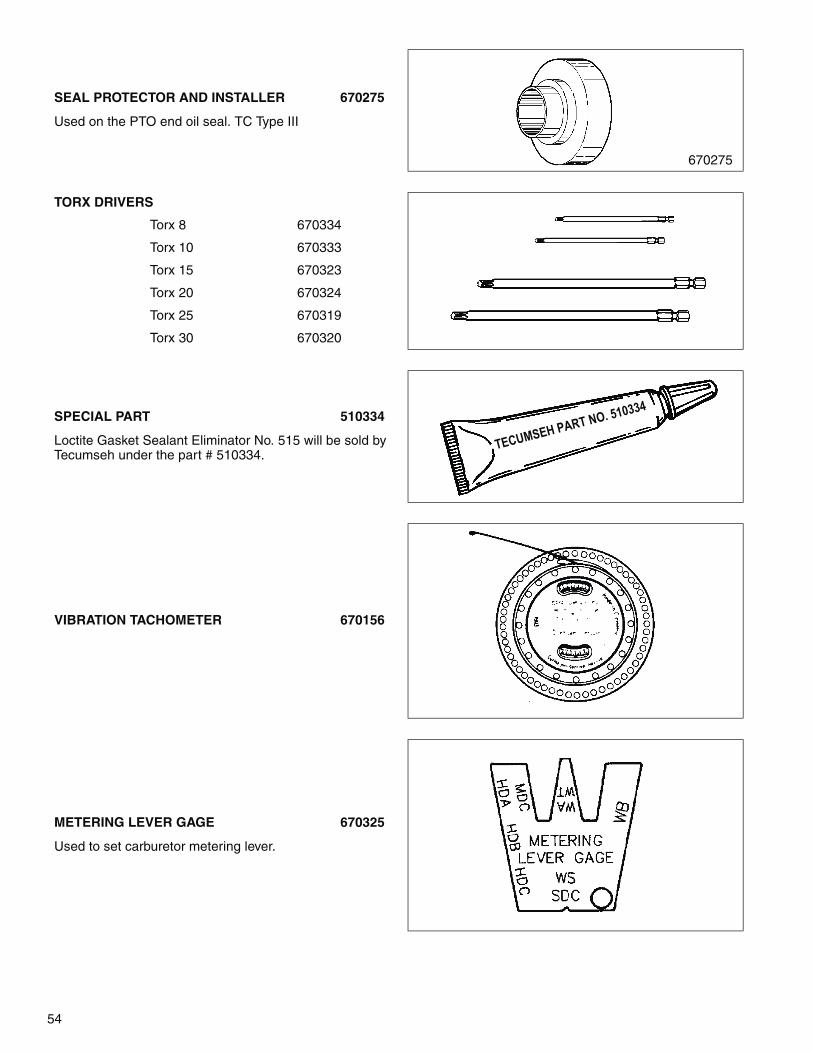
SEAL PROTECTOR AND INSTALLER 670275
Used on the PTO end oil seal. TC Type III
TORX DRIVERS
Torx 8 670334
Torx 10 670333
Torx 15 670323
Torx 20 670324
Torx 25 670319
Torx 30 670320
SPECIAL PART 510334
Loctite Gasket Sealant Eliminator No. 515 will be sold by Tecumseh under the part # 510334.
VIBRATION TACHOMETER 670156
METERING LEVER GAGE 670325
Used to set carburetor metering lever.
670275
TECUMSEH PART NO. 510334

This manual covers all TC and TM models.
Other illustrated Tecumseh 2-Cycle Engine, 4-Cycle Engine and Transmission Technician’s Handbooks and wall charts
are available through Tecumseh.
For complete listing write or call
Form No. 694782 Rev. 1/05 Litho in U.S.A.
Tecumseh Power Company900 North Street
Grafton, WI 53024Phone: 262-377-2700
Fax: 262-377-4485
Tecumseh Europa S.p.A.Strada delle Cacce, 99
10135 Torino, ItalyTel. (39) 0 11 391-8411
Telefax (39) 0 11 3910031
www.TecumsehPower.com
ENGINES TRANSMISSIONS&
740109