TESTASTRETTA VALVE ADJUSTMENT - · PDF file1 TESTASTRETTA VALVE ADJUSTMENT This procedure...
10
1 TESTASTRETTA VALVE ADJUSTMENT This procedure applies to all Testastretta engines. Ducati motorcycles are beautiful expressions of form and function. Adhering to the maintenance intervals is important to ensure optimum performance. There is an urban legend that Ducati valve adjustment is mysterious and difficult. This guide will dispel that myth and help you understand the ease with which valve clearance measurement and adjustment can be accomplished. There are several methods for taking the measurements of the shims. In much of the written information and on the web forums the terms “Loaded” and “Unloaded” are frequently used. These terms evolved from working on 2-Valve and earlier Desmoquattro (4 Valve) valve trains where access was limited due to the cylinder head design. These methods will give valid results for the Testastretta engines, but are not required. Ducati has made measuring these clearances very easy. If this is your first time measuring and adjusting the desmodromic engines, take your time and enjoy working on your bike. Getting to the cylinder heads is the first step in the process. DISASSEMBLY Secure the bike to a stand or a lift. Take pictures of everything, especially electrical connections and routing of leads, hoses, etc. to aid in reassembly. Use a paint pen or other marking device to make alignment marks (i.e.-oil pressure sensor connection) for reassembly purposes. Remove the side fairings Disconnect the battery (the battery negative terminal is the first removed and the last installed) Remove enough interference to gain access to the cylinder heads. This may include the fuel tank/seat cowling assembly, the air-box, and radiator. Get a picture of cooling fan connections (both sides). Place a catch pan underneath the radiator hoses to catch the fluid during removal Remove coil Remove the spark plugs Remove the rocker cover Remove the timing belt covers: Undo the bolts securing the vertical timing belt cover and remove it from the vertical cylinder assembly. Some finesse may be required as this is a tight fit in the frame. Undo the bolts securing the timing belt cover and remove it from the horizontal cylinder unit. Remove the spark plugs. This is important: the engine will not rotate with the spark plugs installed. The engine will have to be rotated during valve adjustment/belt replacement and is made easier with the removal of the spark plugs.
Transcript of TESTASTRETTA VALVE ADJUSTMENT - · PDF file1 TESTASTRETTA VALVE ADJUSTMENT This procedure...
1
TESTASTRETTA VALVE ADJUSTMENT
This procedure applies to all Testastretta engines. Ducati motorcycles are beautiful expressions of form and
function. Adhering to the maintenance intervals is important to ensure optimum performance. There is an urban
legend that Ducati valve adjustment is mysterious and difficult. This guide will dispel that myth and help you
understand the ease with which valve clearance measurement and adjustment can be accomplished.
There are several methods for taking the measurements of the shims. In much of the written information and on
the web forums the terms “Loaded” and “Unloaded” are frequently used. These terms evolved from working on
2-Valve and earlier Desmoquattro (4 Valve) valve trains where access was limited due to the cylinder head design.
These methods will give valid results for the Testastretta engines, but are not required. Ducati has made
measuring these clearances very easy. If this is your first time measuring and adjusting the desmodromic engines,
take your time and enjoy working on your bike. Getting to the cylinder heads is the first step in the process.
DISASSEMBLY
Secure the bike to a stand or a lift. Take pictures of everything, especially electrical connections and routing of
leads, hoses, etc. to aid in reassembly.
Use a paint pen or other marking device to make alignment marks (i.e.-oil pressure sensor connection) for
reassembly purposes.
Remove the side fairings
Disconnect the battery (the battery negative terminal is the first removed and the last installed)
Remove enough interference to gain access to the cylinder heads. This may include the fuel tank/seat cowling
assembly, the air-box, and radiator. Get a picture of cooling fan connections (both sides). Place a catch pan
underneath the radiator hoses to catch the fluid during removal
Remove coil
Remove the spark plugs
Remove the rocker cover
Remove the timing belt covers:
Undo the bolts securing the vertical timing belt cover and remove it from the vertical cylinder assembly. Some
finesse may be required as this is a tight fit in the frame.
Undo the bolts securing the timing belt cover and remove it from the horizontal cylinder unit.
Remove the spark plugs. This is important: the engine will not rotate with the spark plugs installed. The engine
will have to be rotated during valve adjustment/belt replacement and is made easier with the removal of the
spark plugs.
2
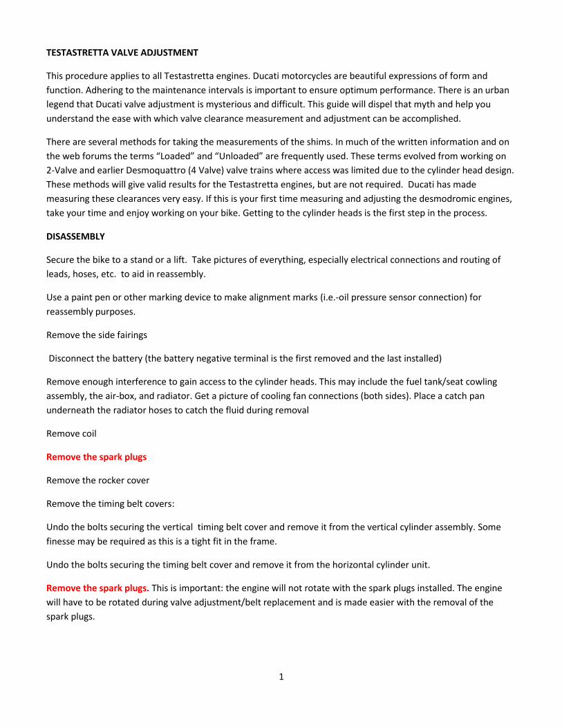
Once the spark plugs are removed, the engine turning tool can
be installed. Remove the cover on the left side of the engine and
install the engine turning tool onto the end of the crankshaft.
Note: the tangs on the engine turning tool fit neatly into indents
on the crank shaft. Tighten the bolt to snug and the engine is
ready to turn counter clockwise (CCW) into the correct
position(s) for valve clearance checking.
Place the engine in the “home” position. The “home” position is realized when the horizontal cylinder is at Top
Dead Center (TDC): the compression stroke of the horizontal cylinder. From the left-hand side of the engine,
rotate the engine slowly counterclockwise to locate TDC. There are several ways to find TDC. The easiest way is to
stick your thumb in the spark plug hole on the horizontal cylinder and rotate the engine until you find
compression coming from the cylinder. Stop at the top of the stroke.
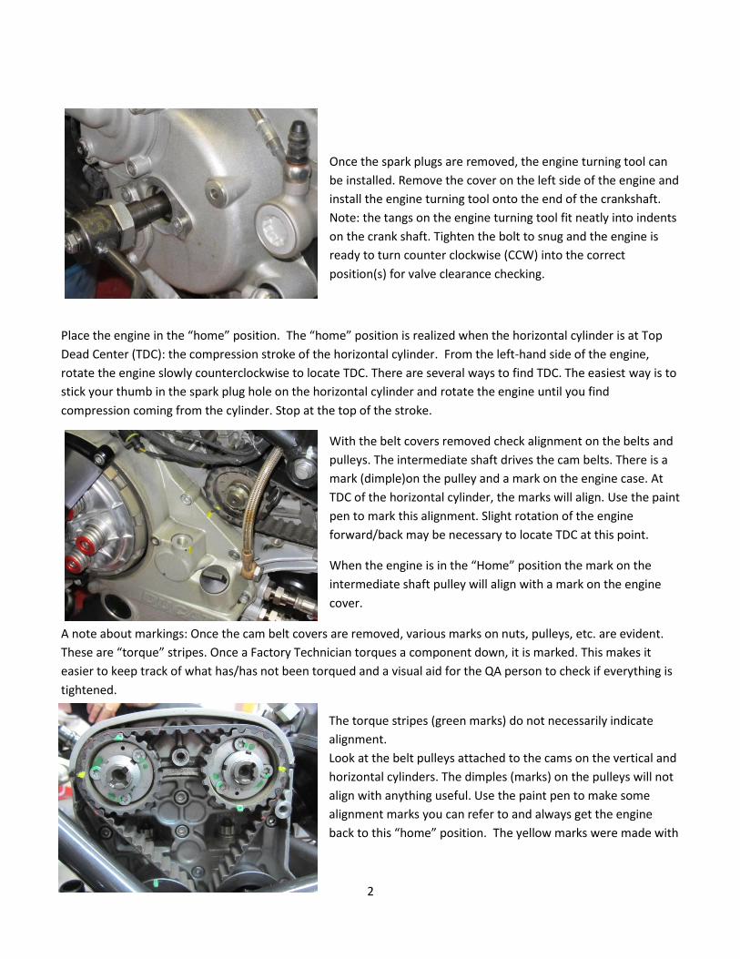
With the belt covers removed check alignment on the belts and
pulleys. The intermediate shaft drives the cam belts. There is a
mark (dimple)on the pulley and a mark on the engine case. At
TDC of the horizontal cylinder, the marks will align. Use the paint
pen to mark this alignment. Slight rotation of the engine
forward/back may be necessary to locate TDC at this point.
When the engine is in the “Home” position the mark on the
intermediate shaft pulley will align with a mark on the engine
cover.
A note about markings: Once the cam belt covers are removed, various marks on nuts, pulleys, etc. are evident.
These are “torque” stripes. Once a Factory Technician torques a component down, it is marked. This makes it
easier to keep track of what has/has not been torqued and a visual aid for the QA person to check if everything is
tightened.
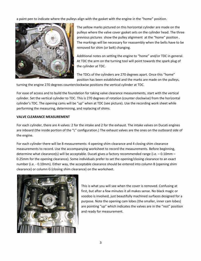
The torque stripes (green marks) do not necessarily indicate
alignment.
Look at the belt pulleys attached to the cams on the vertical and
horizontal cylinders. The dimples (marks) on the pulleys will not
align with anything useful. Use the paint pen to make some
alignment marks you can refer to and always get the engine
back to this “home” position. The yellow marks were made with
3
a paint pen to indicate where the pulleys align with the gasket with the engine in the “home” position.
The yellow marks pictured on this horizontal cylinder are made on the
pulleys where the valve cover gasket sets on the cylinder head. The three
previous pictures show the pulley alignment at the “home” position .
The markings will be necessary for reassembly when the belts have to be
removed for shim (or belt) changing.
Additional notes on setting the engine to “home” and/or TDC in general.
At TDC the arm on the turning tool will point towards the spark plug of
the cylinder at TDC.
The TDCs of the cylinders are 270 degrees apart. Once this “home”
position has been established and the marks are made on the pulleys,
turning the engine 270 degrees counterclockwise positions the vertical cylinder at TDC.
For ease of access and to build the foundation for taking valve clearance measurements, start with the vertical
cylinder. Set the vertical cylinder to TDC. This is 270 degrees of rotation (counter clockwise) from the horizontal
cylinder’s TDC. The opening cams will be “up” when at TDC (see picture). Use the recording work sheet while
performing the measuring, determining, and replacing of shims.
VALVE CLEARANCE MEASUREMENT
For each cylinder, there are 4 valves: 2 for the intake and 2 for the exhaust. The intake valves on Ducati engines
are inboard (the inside portion of the “L” configuration.) The exhaust valves are the ones on the outboard side of
the engine.
For each cylinder there will be 8 measurements: 4 opening shim clearance and 4 closing shim clearance
measurements to record. Use the accompanying worksheet to record the measurements. Before beginning,
determine what clearance(s) will be acceptable. Ducati gives a factory recommended range (i.e. – 0.10mm –
0.25mm for the opening clearance). Some individuals prefer to set the opening/closing clearance to an exact
number (i.e. - 0.10mm). Either way, the acceptable clearance should be entered into column B (opening shim
clearance) or column G (closing shim clearance) on the worksheet.
This is what you will see when the cover is removed. Confusing at
first, but after a few minutes it all makes sense. No black magic or
voodoo is involved, just beautifully machined surfaces designed for a
purpose. Note the opening cam lobes (the smaller, inner cam lobes)
are pointing “up” which indicates the valves are in the “rest” position
and ready for measurement.
4
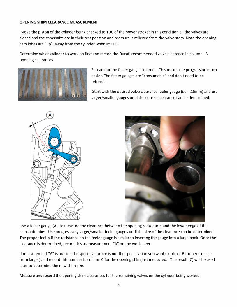
OPENING SHIM CLEARANCE MEASUREMENT
Move the piston of the cylinder being checked to TDC of the power stroke: in this condition all the valves are
closed and the camshafts are in their rest position and pressure is relieved from the valve stem. Note the opening
cam lobes are “up”, away from the cylinder when at TDC.
Determine which cylinder to work on first and record the Ducati recommended valve clearance in column B
opening clearances
Spread out the feeler gauges in order. This makes the progression much
easier. The feeler gauges are “consumable” and don’t need to be
returned.
Start with the desired valve clearance feeler gauge (i.e. -.15mm) and use
larger/smaller gauges until the correct clearance can be determined.
Use a feeler gauge (A), to measure the clearance between the opening rocker arm and the lower edge of the
camshaft lobe: Use progressively larger/smaller feeler gauges until the size of the clearance can be determined.
The proper feel is if the resistance on the feeler gauge is similar to inserting the gauge into a large book. Once the
clearance is determined, record this as measurement “A” on the worksheet.
If measurement “A” is outside the specification (or is not the specification you want) subtract B from A (smaller
from larger) and record this number in column C for the opening shim just measured. The result (C) will be used
later to determine the new shim size.
Measure and record the opening shim clearances for the remaining valves on the cylinder being worked.
5
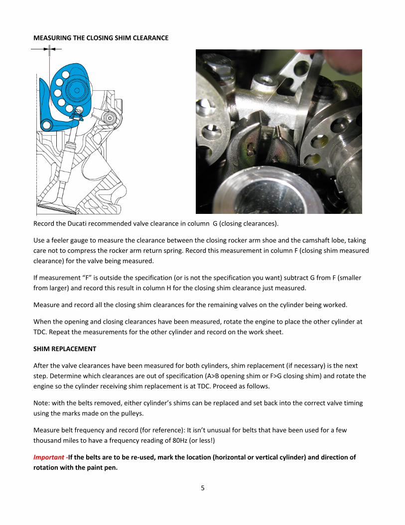
MEASURING THE CLOSING SHIM CLEARANCE
Record the Ducati recommended valve clearance in column G (closing clearances).
Use a feeler gauge to measure the clearance between the closing rocker arm shoe and the camshaft lobe, taking
care not to compress the rocker arm return spring. Record this measurement in column F (closing shim measured
clearance) for the valve being measured.
If measurement “F” is outside the specification (or is not the specification you want) subtract G from F (smaller
from larger) and record this result in column H for the closing shim clearance just measured.
Measure and record all the closing shim clearances for the remaining valves on the cylinder being worked.
When the opening and closing clearances have been measured, rotate the engine to place the other cylinder at
TDC. Repeat the measurements for the other cylinder and record on the work sheet.
SHIM REPLACEMENT
After the valve clearances have been measured for both cylinders, shim replacement (if necessary) is the next
step. Determine which clearances are out of specification (A>B opening shim or F>G closing shim) and rotate the
engine so the cylinder receiving shim replacement is at TDC. Proceed as follows.
Note: with the belts removed, either cylinder’s shims can be replaced and set back into the correct valve timing
using the marks made on the pulleys.
Measure belt frequency and record (for reference): It isn’t unusual for belts that have been used for a few
thousand miles to have a frequency reading of 80Hz (or less!)
Important -If the belts are to be re-used, mark the location (horizontal or vertical cylinder) and direction of
rotation with the paint pen.
6
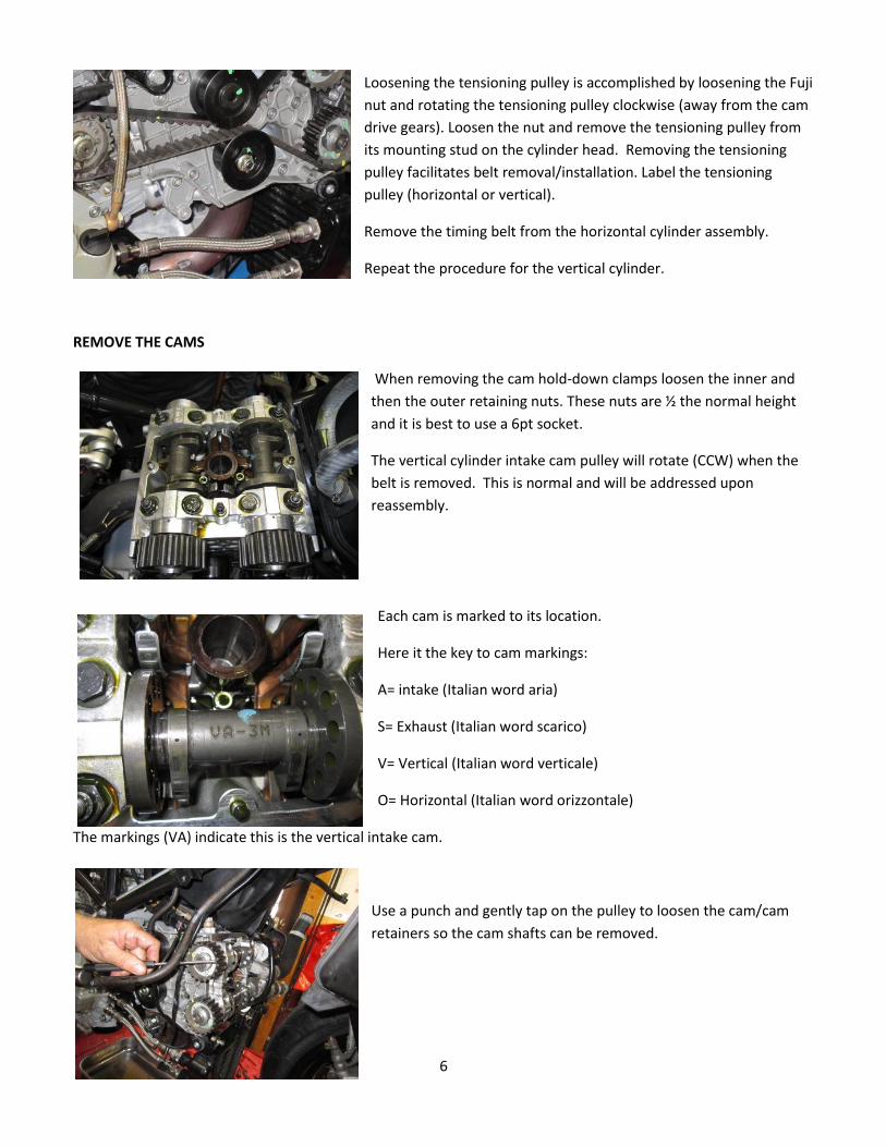
Loosening the tensioning pulley is accomplished by loosening the Fuji
nut and rotating the tensioning pulley clockwise (away from the cam
drive gears). Loosen the nut and remove the tensioning pulley from
its mounting stud on the cylinder head. Removing the tensioning
pulley facilitates belt removal/installation. Label the tensioning
pulley (horizontal or vertical).
Remove the timing belt from the horizontal cylinder assembly.
Repeat the procedure for the vertical cylinder.
REMOVE THE CAMS
When removing the cam hold-down clamps loosen the inner and
then the outer retaining nuts. These nuts are ½ the normal height
and it is best to use a 6pt socket.
The vertical cylinder intake cam pulley will rotate (CCW) when the
belt is removed. This is normal and will be addressed upon
reassembly.
Each cam is marked to its location.
Here it the key to cam markings:
A= intake (Italian word aria)
S= Exhaust (Italian word scarico)
V= Vertical (Italian word verticale)
O= Horizontal (Italian word orizzontale)
The markings (VA) indicate this is the vertical intake cam.
Use a punch and gently tap on the pulley to loosen the cam/cam
retainers so the cam shafts can be removed.
7
OPENING SHIM REPLACEMTNT:
With the cam removed, the opening shim will lift off of the valve.
Hold the opening rocker out of the way. Use a magnet or needle
nose pliers to remove the opening shim. If replacing more than
one opening shim put it in a marked container (plastic bag, egg
crate, etc. so it doesn’t get mixed up with other shims.
Here is the horizontal cylinder with the cams removed. You can
see the opening shim has been removed from the valve on the
left and the closing shim is accessible.
The valve on the right still has the opening shim installed
The opening shims are
flat on the top and
recessed on the bottom
so the shim fits on top
of the valve stem securely
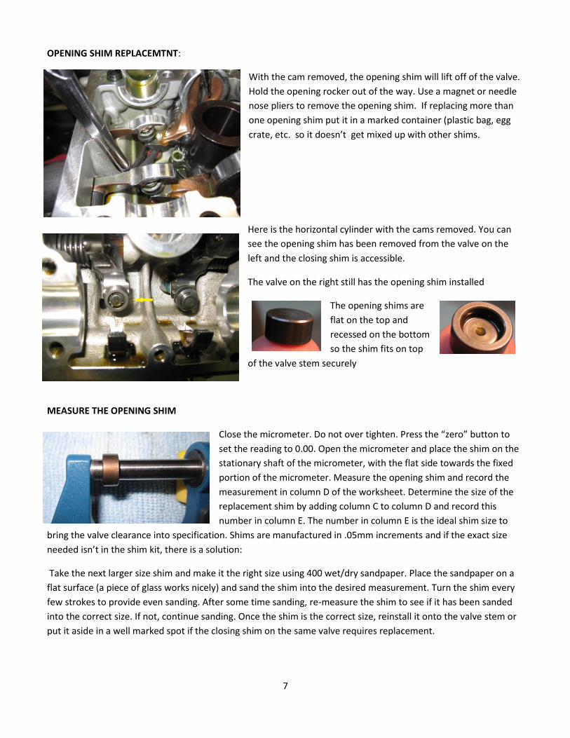
MEASURE THE OPENING SHIM
Close the micrometer. Do not over tighten. Press the “zero” button to
set the reading to 0.00. Open the micrometer and place the shim on the
stationary shaft of the micrometer, with the flat side towards the fixed
portion of the micrometer. Measure the opening shim and record the
measurement in column D of the worksheet. Determine the size of the
replacement shim by adding column C to column D and record this
number in column E. The number in column E is the ideal shim size to
bring the valve clearance into specification. Shims are manufactured in .05mm increments and if the exact size
needed isn’t in the shim kit, there is a solution:
Take the next larger size shim and make it the right size using 400 wet/dry sandpaper. Place the sandpaper on a
flat surface (a piece of glass works nicely) and sand the shim into the desired measurement. Turn the shim every
few strokes to provide even sanding. After some time sanding, re-measure the shim to see if it has been sanded
into the correct size. If not, continue sanding. Once the shim is the correct size, reinstall it onto the valve stem or
put it aside in a well marked spot if the closing shim on the same valve requires replacement.
8
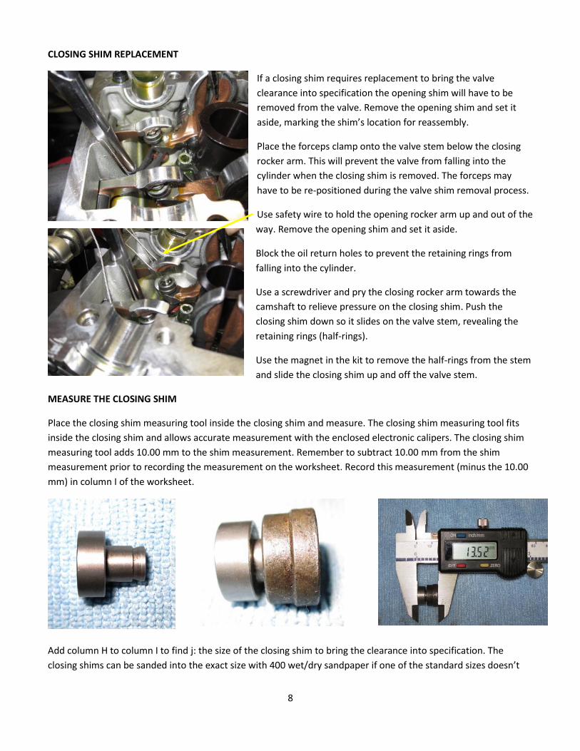
CLOSING SHIM REPLACEMENT
If a closing shim requires replacement to bring the valve
clearance into specification the opening shim will have to be
removed from the valve. Remove the opening shim and set it
aside, marking the shim’s location for reassembly.
Place the forceps clamp onto the valve stem below the closing
rocker arm. This will prevent the valve from falling into the
cylinder when the closing shim is removed. The forceps may
have to be re-positioned during the valve shim removal process.
Use safety wire to hold the opening rocker arm up and out of the
way. Remove the opening shim and set it aside.
Block the oil return holes to prevent the retaining rings from
falling into the cylinder.
Use a screwdriver and pry the closing rocker arm towards the
camshaft to relieve pressure on the closing shim. Push the
closing shim down so it slides on the valve stem, revealing the
retaining rings (half-rings).
Use the magnet in the kit to remove the half-rings from the stem
and slide the closing shim up and off the valve stem.
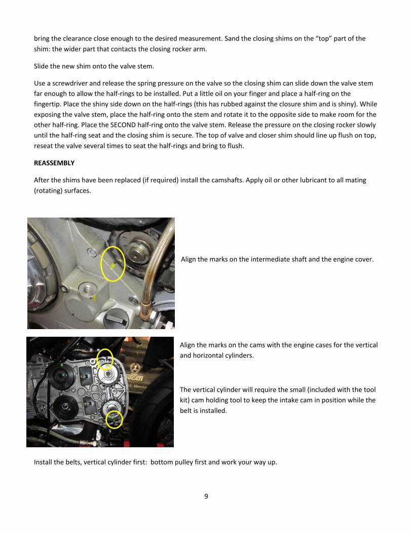
MEASURE THE CLOSING SHIM
Place the closing shim measuring tool inside the closing shim and measure. The closing shim measuring tool fits
inside the closing shim and allows accurate measurement with the enclosed electronic calipers. The closing shim
measuring tool adds 10.00 mm to the shim measurement. Remember to subtract 10.00 mm from the shim
measurement prior to recording the measurement on the worksheet. Record this measurement (minus the 10.00
mm) in column I of the worksheet.
Add column H to column I to find j: the size of the closing shim to bring the clearance into specification. The
closing shims can be sanded into the exact size with 400 wet/dry sandpaper if one of the standard sizes doesn’t
9
bring the clearance close enough to the desired measurement. Sand the closing shims on the “top” part of the
shim: the wider part that contacts the closing rocker arm.
Slide the new shim onto the valve stem.
Use a screwdriver and release the spring pressure on the valve so the closing shim can slide down the valve stem
far enough to allow the half-rings to be installed. Put a little oil on your finger and place a half-ring on the
fingertip. Place the shiny side down on the half-rings (this has rubbed against the closure shim and is shiny). While
exposing the valve stem, place the half-ring onto the stem and rotate it to the opposite side to make room for the
other half-ring. Place the SECOND half-ring onto the valve stem. Release the pressure on the closing rocker slowly
until the half-ring seat and the closing shim is secure. The top of valve and closer shim should line up flush on top,
reseat the valve several times to seat the half-rings and bring to flush.
REASSEMBLY
After the shims have been replaced (if required) install the camshafts. Apply oil or other lubricant to all mating
(rotating) surfaces.
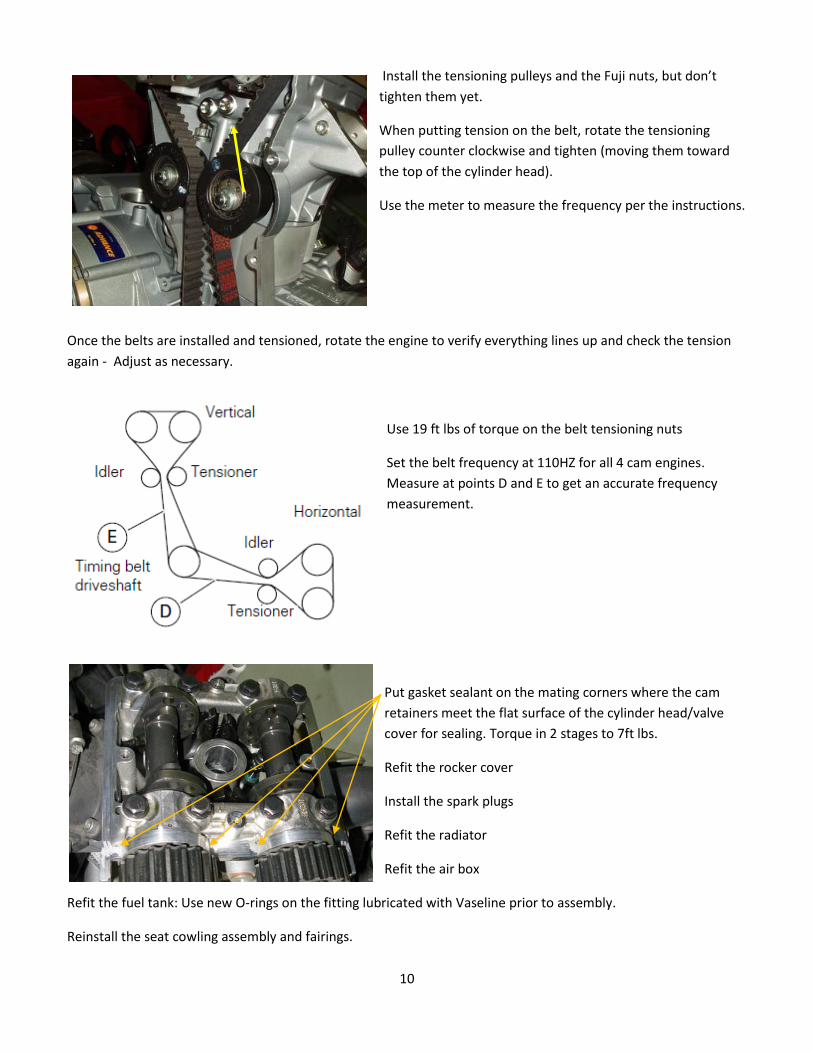
Align the marks on the intermediate shaft and the engine cover.
Align the marks on the cams with the engine cases for the vertical
and horizontal cylinders.
The vertical cylinder will require the small (included with the tool
kit) cam holding tool to keep the intake cam in position while the
belt is installed.
Install the belts, vertical cylinder first: bottom pulley first and work your way up.
10
Install the tensioning pulleys and the Fuji nuts, but don’t
tighten them yet.
When putting tension on the belt, rotate the tensioning
pulley counter clockwise and tighten (moving them toward
the top of the cylinder head).
Use the meter to measure the frequency per the instructions.
Once the belts are installed and tensioned, rotate the engine to verify everything lines up and check the tension
again - Adjust as necessary.
Use 19 ft lbs of torque on the belt tensioning nuts
Set the belt frequency at 110HZ for all 4 cam engines.
Measure at points D and E to get an accurate frequency
measurement.
Put gasket sealant on the mating corners where the cam
retainers meet the flat surface of the cylinder head/valve
cover for sealing. Torque in 2 stages to 7ft lbs.
Refit the rocker cover
Install the spark plugs
Refit the radiator
Refit the air box
Refit the fuel tank: Use new O-rings on the fitting lubricated with Vaseline prior to assembly.
Reinstall the seat cowling assembly and fairings.


![Index [ducati.hr]€¦ · Ducati Testastretta DVT The difference is in the detail. With the 1262 cc Ducati Testastretta DVT, the detail is known as Desmodromic Variable Timing (DVT),](https://static.fdocuments.in/doc/165x107/5f594aa219a8ad14dd49816e/index-ducati-testastretta-dvt-the-difference-is-in-the-detail-with-the-1262.jpg)