
Test Plan for EAC VVSG 1.0 Certification Testing Election ...

Derived Test Requirements for Next VVSG Security Requirements
Version 0.9244August 25, 2008
DRAFT
Please send all comments to:
Nelson HastingsNational Institute of Standards and TechnologyInformation Technology Laboratory100 Bureau Drive, Stop 8930Gaithersburg MD 20899-8930
This document and associated files have been prepared by the National Institute of Standards and Technology (NIST) and represent draft test
materials for the Election Assistance Commission's next iteration of the VVSG. It is a preliminary draft and does not represent a consensus view or recommendation from NIST, nor does it represent any policy positions of
NIST.

Product DisclaimerCertain commercial entities, equipment, or material may be identified in the document in order to describe an experimental procedure or concept adequately. Such identification is not intended to imply recommendation or endorsement by the National Institute of Standards and Technology, nor is it intended to imply that these entities, materials, or equipment are necessarily the best available for the purpose.
2

TABLE OF CONTENTS
1 Introduction..................................................................................................271.1 Background......................................................................................................271.2 Purpose............................................................................................................271.3 Scope...............................................................................................................271.4 Approach..........................................................................................................271.5 Notation and Derived Test Requirement (DTR) Structure...............................28
1.5.1 DTR Structure.........................................................................................................281.5.2 Angle Bracket (<…>) Notation.................................................................................291.5.3 Backslash ( / ) Notation...........................................................................................291.5.4 Asterisk (*) Notation................................................................................................301.5.5 Use of the Term “Shall”...........................................................................................301.5.6 Electronic File Features for Word Versions of the Document..................................30
1.6 Product Specific Test Procedures....................................................................301.7 General Testing Assumptions..........................................................................30
2 Definitions...................................................................................................323 Interface Testing........................................................................................334 Cryptography..............................................................................................345 Setup Inspection........................................................................................526 Software Installation..................................................................................747 Access Control...........................................................................................948 System Integrity Management................................................................1299 Communication Security.........................................................................14310 System Event Logging.............................................................................15911 Physical Security for Voting Devices.....................................................17912 Audit..........................................................................................................19213 Audit Test Ballot Specification – Simple................................................26914 Audit Test Ballot Specification – Complex............................................27115 System Event Log Coverage...................................................................27416 Verifying Apache 2.2 TLS Configuration on Linux................................285
16.1 Verifying TLS Configuration for Apache Server.............................................28616.1.1 Verifying Integrity Algorithm Strength....................................................................28616.1.2 Verifying the Configured Algorithm Selection........................................................29016.1.3 Verifying Authentication Algorithm Strength..........................................................292
16.2 Verifying Mutually Authenticated TLS............................................................29316.2.1 Verifying Trust Anchor Signature Algorithms.........................................................29316.2.2 Verifying CA Certificates........................................................................................29416.2.3 Verifying Client Certificate Signature Algorithms...................................................294
17 Verifying IIS 6.0 Configuration on Windows 2003 Server.....................29617.1 Verifying TLS Configuration for IIS 6.0..........................................................297
3

17.1.1 Verifying Integrity Algorithm Strength....................................................................29717.1.2 Verifying the Configured Algorithm Selection........................................................30017.1.3 Verifying Authentication Algorithm Strength..........................................................302
17.2 Verifying Mutually Authenticated TLS............................................................30317.2.1 Verifying Trust Anchor Signature Algorithms.........................................................30317.2.2 Verifying CA Certificates........................................................................................30417.2.3 Verifying Client Certificate Signature Algorithms...................................................304
18 Bibliography.............................................................................................30619 List of Acronyms.........................................................................................307
LIST OF FIGURES AND TABLES
Table 4-1: Cryptographic Modules and Algorithms.......................................................................36Table 4-2: Cryptographic Algorithms and Key Sizes.....................................................................37Table 7-1: Access Methods..........................................................................................................94Table 7-2: Functions and Roles....................................................................................................96Table 7-3: Functions and Privileges..............................................................................................97Table 8-1: Malware Detection Software......................................................................................138Table 9-1: Communication Ports Information..............................................................................149Table 12-1: Votes for Summary Count Report............................................................................205Table 12-2: Summary Count Reports Fed to EMS.....................................................................214Table 12-3: EMS Internal State After Provisional Ballot Adjudication.........................................220Table 15-1: System Event Log Coverage...................................................................................274
LIST OF DTR
RE 5.1.1-A Cryptographic module validation:......................................................33AS 5.1.1-A-1 Cryptographic module validation:............................................................33
MA 5.1.1-A-1.1 Cryptographic module validation information – Module Information:............33MA 5.1.1-A-1.2 Cryptographic module validation information – Algorithm Information:.........33TE 5.1.1-A-1.1 Cryptographic module validation information verification -- Modules:...........33TE 5.1.1-A-1.2 Cryptographic module validation environment verification:............................34TE 5.1.1-A-1.3 Cryptographic module validation description verification:..............................34TE 5.1.1-A-1.4 Cryptographic module validation configuration verification:...........................34TE 5.1.1-A-1.5 Cryptographic module validation algorithm verification:.................................35
RE 5.1.1-B Cryptographic strength:.................................................................35AS 5.1.1-B-1 Cryptographic strength – Key Size:........................................................36
MA 5.1.1-B-1.1 Cryptographic strength:................................................................................36TE 5.1.1-B-1.1 Cryptographic strength – Key Size:...............................................................36
AS 5.1.1-B-2 Cryptographic strength – MAC Size:.......................................................37TE 5.1.1-B-2.1 Cryptographic strength – MAC Size:.............................................................37
RE 5.1.2-A Digital signature generation requirements:.................................37AS 5.1.2-A-1 Digital signature generation requirements:.............................................37
MA 5.1.2-A-1.1 Digital signature generation requirements – SM Identification:.....................38MA 5.1.2-A-1.2 Digital signature generation requirements – election records:......................38TE 5.1.2-A-1.1 Digital signature generation requirements – module rating:..........................38TE 5.1.2-A-1.2 Digital signature generation requirements – key invocation:.........................38
RE 5.1.2-B Signature Module (SM):..................................................................38AS 5.1.2-B-1 Signature Module (SM) – key generation:..............................................38
TE 5.1.2-B-1.1 Signature Module (SM) – key generation:.....................................................39AS 5.1.2-B-2 Signature Module (SM) – key protection:...............................................39
4

AS 5.1.2-B-3 Signature Module (SM) – digital signature generation:...........................39
RE 5.1.2-B.1 Non-replaceable embedded Signature Module (SM):...............39AS 5.1.2-B.1-1 Non-replaceable embedded Signature Module (SM):.........................39
TE 5.1.2-B.1-1.1 Non-replaceable embedded Signature Module (SM):.................................39
RE 5.1.2-B.2 Signature module validation level:............................................39RE 5.1.3.1-A DSK Generation:..........................................................................40
AS 5.1.3.1-A-1 DSK Generation:..................................................................................40TE 5.1.3.1-A-1.1 DSK Generation -- non-deterministic random bit generator:.......................40TE 5.1.3.1-A-1.2 DSK Generation – using only non-deterministic random bit generator:......40TE 5.1.3.1-A-1.3 DSK Generation – Permanent:...................................................................40
RE 5.1.3.1-B Device certificate generation:.....................................................40AS 5.1.3.1-B-1 Device certificate generation:...............................................................40
MA 5.1.3.1-B-1.1 Device certificate generation:....................................................................41TE 5.1.3.1-B-1.1 Device certificate generation – Common Examination:..............................41*****TE 5.1.3.1-B-1.2 Device certificate generation – CA Signed:.........................................41*****TE 5.1.3.1-B-1.3 Device certificate generation – Self-Signed:........................................42
RE 5.1.3-C Device Certificate storage:............................................................43AS 5.1.3-C-1 Device Certificate storage – permanent:................................................43
TE 5.1.3-C-1.1 Device Certificate storage – permanent:.......................................................43
RE 5.1.3-D Device identification placard:........................................................43AS 5.1.3-D-1 Device identification placard:..................................................................43
TE 5.1.3-D-1.1 Device identification placard:.........................................................................43
RE 5.1.3-E Device Signature Key protection:.................................................43AS 5.1.3-E-1 Device Signature Key protection – Generation:......................................43AS 5.1.3-E-2 Device Signature Key protection – Exists:..............................................44AS 5.1.3-E-3 Device Signature Key protection – Alter:................................................44
MA 5.1.3-E-3.1 Device Signature Key protection – Alter:......................................................44TE 5.1.3-E-3.1 Device Signature Key protection – Alter:.......................................................44
AS 5.1.3-E-4 Device Signature Key protection – Export:.............................................44TE 5.1.3-E-4.1 Device Signature Key protection – Export:....................................................44
RE 5.1.3-F Use of Device Signature Key:........................................................44AS 5.1.3-F-1 Use of Device Signature Key:.................................................................45
MA 5.1.3-F-1.1 Use of Device Signature Key:.......................................................................45TE 5.1.3-F-1.1 Use of Device Signature Key – Election Public Key Certificate:....................45TE 5.1.3-F-1.2 Use of Device Signature Key – Election Close Out Records:........................46TE 5.1.3-F-1.3 Use of Device Signature Key – Device Public Key Certificate:......................46TE 5.1.3-F-1.4 Use of Device Signature Key – Other Uses:..................................................46
RE 5.1.4-A Election Signature Key (ESK) generation:...................................47RE 5.1.4-B Election Public Key Certificate:.....................................................47RE 5.1.4-C Election counter:............................................................................47
AS 5.1.4-C-1 Election counter:.....................................................................................47TE 5.1.4-C-1.1 Election counter:............................................................................................47
RE 5.1.4-D Election Signature Key use counter:............................................48AS 5.1.4-D-1 Election Signature Key use counter:.......................................................48
MA 5.1.4-D-1.1 Election Signature Key use counter:.............................................................48TE 5.1.4-D-1.1 Election Signature Key use counter: Update:................................................48
5

RE 5.1.4-E Election Key Closeout:...................................................................49AS 5.1.4-E-1 Election Key Closeout:............................................................................49
TE 5.1.4-E-1.1 Election Key Closeout: Key Destruction:.......................................................49
RE 5.1.4-F Election Key Closeout record:.......................................................50RE 5.2.1.1-A Voting device software identification:.......................................51
AS 5.2.1.1-A-1 Voting device software identification:...................................................51MA 5.2.1.1-A-1.1 Voting device software identification – location:.........................................51MA 5.2.1.1-A-1.2 Voting device software identification – software identification method:......51TE 5.2.1.1-A-1.1 Voting device software identification:..........................................................51
RE 5.2.1.1-B Voting device, software identification verification log:............51AS 5.2.1.1-B-1 Voting device, software identification verification log:..........................51
MA 5.2.1.1-B-1.1 Voting device, software identification verification log – location:................52MA 5.2.1.1-B-1.2 Voting device, software identification verification log – identification:........52MA 5.2.1.1-B-1.3 Voting device, software identification verification log – interpretation:.......52TE 5.2.1.1-B-1.1 Voting device, software identification verification log:.................................52
RE 5.2.1.1-B.1 EMS, software identification verification log:........................53RE 5.2.1.2-A Software integrity verification:...................................................53
AS 5.2.1.2-A-1 Software integrity verification:..............................................................53MA 5.2.1.2-A-1.1 Software integrity verification:....................................................................53TE 5.2.1.2-A-1.1 Software integrity verification – name:........................................................53TE 5.2.1.2-A-1.2 Software integrity verification – cryptographic software reference information:............................................................................................................................ 53TE 5.2.1.2-A-1.3 Software integrity verification – positive case:............................................54TE 5.2.1.2-A-1.4 Software integrity verification – unauthorized software modification:..........54TE 5.2.1.2-A-1.5 Software integrity verification – unauthorized cryptographic software information modification:........................................................................................................54*****TE 5.2.1.2-A-1.6 Software integrity verification – signature modification:.......................54
RE: 5.2.1.2-B Voting device, software integrity verification log:...................54AS: 5.2.1.2-B-1 Voting device, software integrity verification log:................................55
MA 5.2.1.2-B-1.1 Voting device, software integrity verification log – location:.......................55MA 5.2.1.2-B-1.2 Voting device, software integrity verification log – identification:................55MA 5.2.1.2-B-1.3 Voting device, software integrity verification log – interpretation:...............55TE 5.2.1.2-B-1.1 Voting device, software integrity verification log:........................................55
RE: 5.2.1.2-B.1 EMS, software integrity verification log:...............................56RE 5.2.2-A Election information value determination:...................................56
AS 5.2.2-A-1 Election information value determination:...............................................57MA 5.2.2-A-1.1 Election information value determination -- list:............................................57MA 5.2.2-A-1.2 Election information value determination -- values:......................................57TE 5.2.2-A-1.1 Election information value determination:......................................................57
RE 5.2.2-B Voting device, election information value inspection log:.........58AS 5.2.2-B-1 Voting device, election information value inspection log:.......................58
MA 5.2.2-B-1.1 Voting device, election information value inspection log – location:..............58MA 5.2.2-B-1.2 Voting device, election information value inspection log – identification:......58MA 5.2.2-B-1.3 Voting device, election information value inspection log – interpretation:.....58TE 5.2.2-B-1.1 Voting device, election information value inspection log:...............................59
RE 5.2.2-B.1 EMS, election information value inspection log:......................59RE 5.2.3-A Backup power source charge indicator:......................................59
6

AS 5.2.3-A-1 Backup power source charge indicator:..................................................59MA 5.2.3-A-1.1 Backup power source charge indicator:........................................................59TE 5.2.3-A-1.1 Backup power source charge indicator – location:........................................59TE 5.2.3-A-1.2 Backup power source charge indicator – precision:......................................60TE 5.2.3-A-1.3 Backup power source charge indicator – full:................................................60TE 5.2.3-A-1.4 Backup power source charge indicator – fraction:.........................................60
RE 5.2.3-B Cabling connectivity indicator:.....................................................60AS 5.2.3-B-1 Cabling connectivity indicator – power:..................................................61
MA 5.2.3-B-1.1 Cabling connectivity indicator – power:.........................................................61TE 5.2.3-B-1.1 Cabling connectivity indicator – power connected:........................................61TE 5.2.3-B-1.2 Cabling connectivity indicator – power disconnected:...................................61
AS 5.2.3-B-2 Cabling connectivity indicator – communication:....................................61MA 5.2.3-B-2.1 Cabling connectivity indicator – communication:..........................................61*****TE 5.2.3-B-2.1 Cabling connectivity indicator – communications cables connected:......61*****TE 5.2.3-B-2.2 Cabling connectivity indicator – communications cables disconnected at SUT:...................................................................................................................................... 61*****TE 5.2.3-B-2.3 Cabling connectivity indicator – communications cables disconnected at other end:.............................................................................................................................. 62
AS 5.2.3-B-3 Cabling connectivity indicator – other:....................................................62MA 5.2.3-B-3.1 Cabling connectivity indicator – other:..........................................................62*****TE 5.2.3-B-3.1 Cabling connectivity indicator – other cables connected:.......................62*****TE 5.2.3-B-3.2 Cabling connectivity indicator – other cables disconnected at SUT:.......63*****TE 5.2.3-B-3.3 Cabling connectivity indicator – other cables disconnected at other end:............................................................................................................................................... 63
RE 5.2.3-C Communications operational status indicator:...........................63AS 5.2.3-C-1 Communications operational status indicator:........................................63
MA 5.2.3-C-1.1 Communications operational status indicator – setup:.................................63MA 5.2.3-C-1.2 Communications operational status indicator:..............................................63TE 5.2.3-C-1.1 Communications operational status indicator – Yes:.....................................64TE 5.2.3-C-1.2 Communications operational status indicator – Disconnected:.....................64
RE 5.2.3-D Communications on/off indicator:................................................64AS 5.2.3-D-1 Communications on/off indicator:...........................................................64
MA 5.2.3-D-1.1 Communications on/off indicator:.................................................................64MA 5.2.3-D-1.2 Communications on/off indicator – setting:...................................................64TE 5.2.3-D-1.1 Communications on/off indicator – on:..........................................................64TE 5.2.3-D-1.2 Communications on/off indicator – off:..........................................................64
RE 5.2.3-E Consumables remaining indicator:...............................................65AS 5.2.3-E-1 Consumables remaining indicator – ink:.................................................65
MA 5.2.3-E-1.1 Consumables remaining indicator – ink:.......................................................65MA 5.2.3-E-1.2 Consumables remaining indicator – ink cartridge load:................................65TE 5.2.3-E-1.1 Consumables remaining indicator – ink not used:.........................................65TE 5.2.3-E-1.2 Consumables remaining indicator – ink full:..................................................65TE 5.2.3-E-1.3 Consumables remaining indicator – ink partial:.............................................65
AS 5.2.3-E-2 Consumables remaining indicator – cut sheet paper:.............................66MA 5.2.3-E-2.1 Consumables remaining indicator – cut sheet paper:...................................66MA 5.2.3-E-2.2 Consumables remaining indicator – cut sheet paper load:...........................66TE 5.2.3-E-2.1 Consumables remaining indicator – cut sheet paper not used:.....................66TE 5.2.3-E-2.2 Consumables remaining indicator –paper full:...............................................66TE 5.2.3-E-2.3 Consumables remaining indicator – paper partial:.........................................66
AS 5.2.3-E-3 Consumables remaining indicator – paper roll:......................................66MA 5.2.3-E-3.1 Consumables remaining indicator – paper roll:.............................................66MA 5.2.3-E-3.2 Consumables remaining indicator – paper roll load:.....................................66
7

TE 5.2.3-E-3.1 Consumables remaining indicator – paper roll not used:...............................67TE 5.2.3-E-3.2 Consumables remaining indicator – paper roll full:........................................67TE 5.2.3-E-3.3 Consumables remaining indicator – paper roll partial:...................................67
AS 5.2.3-E-4 Consumables remaining indicator – other:.............................................67MA 5.2.3-E-4.1 Consumables remaining indicator – other list:..............................................67MA 5.2.3-E-4.2 Consumables remaining indicator – other indicators:...................................67MA 5.2.3-E-4.3 Consumables remaining indicator – other load:............................................67TE 5.2.3-E-4.1 Consumables remaining indicator – other list:...............................................67TE 5.2.3-E-4.2 Consumables remaining indicator – other full:...............................................67TE 5.2.3-E-4.3 Consumables remaining indicator – other partial:.........................................68
RE 5.2.3-F Calibration determination of voting device components:...........68AS 5.2.3-F-1 Calibration determination of voting device components:........................68
MA 5.2.3-F-1.1 Calibration determination of voting device components – list:......................68MA 5.2.3-F-1.2 Calibration determination of voting device components – inspection:...........68TE 5.2.3-F-1.1 Calibration determination of voting device components – list:.......................68TE 5.2.3-F-1.2 Calibration determination of voting device components – inspection:............69
RE 5.2.3-G Calibration of voting device components adjustment:...............69AS 5.2.3-G-1 Calibration of voting device components adjustment:............................69
MA 5.2.3-G-1.1 Calibration of voting device components adjustment:..................................69TE 5.2.3-G-1.1 Calibration of voting device components adjustment:...................................69
RE 5.2.3-NEW Inspection of properties using software:................................69AS 5.2.3-NEW-1 Inspection of properties using software:...........................................69
MA 5.2.3-NEW-1.1 Inspection of properties using software – list:.........................................69MA 5.2.3-NEW-1.2 Inspection of properties using software – procedures:............................70TE 5.2.3-NEW-1.1 Inspection of properties using software – list:..........................................70TE 5.2.3-New-1.2 Inspection of properties using software:...................................................70
RE 5.2.3-H Voting device, property inspection log:.......................................70AS 5.2.3-H-1 Voting device, property inspection log:...................................................70
MA 5.2.3-H-1.1 Voting device, property inspection log – location:.........................................70MA 5.2.3-H-1.2 Voting device, property inspection log – identification:.................................70MA 5.2.3-H-1.3 Voting device, property inspection log – interpretation:................................71TE 5.2.3-H-1.1 Voting device, property inspection log – calibration inspection:....................71TE 5.2.3-H-1.2 Voting device, property inspection log – calibration adjustment:...................71TE 5.2.3-H-1.3 Voting device, property inspection log – property inspection:........................71
RE: 5.2.3-I EMS, property inspection log:.......................................................72RE 5.3-A Software installation state restriction:............................................73
AS 5.3-A-1 Software installation state restriction – positive:........................................73MA 5.3-A-1.1 Software installation state restriction – state:...................................................73MA 5.3-A-1.2 Software installation state restriction – procedure:..........................................73MA 5.3-A-1.3 Software installation state restriction – location:..............................................73MA 5.3-A-1.4 Software installation log – location:..................................................................73MA 5.3-A-1.5 Software installation log – identification:..........................................................73MA 5.3-A-1.6 Software installation log – interpretation:.........................................................73*****TE 5.3-A-1.1 Software installation state restriction – positive:........................................73
AS 5.3-A-2 Software installation state restriction – negative:.......................................74TE 5.3-A-2.1 Software installation state restriction – activated:.............................................74TE 5.3-A-2.2 Software installation state restriction – suspended:..........................................75TE 5.3-A-2.3 Software installation state restriction – post-voting:..........................................76
RE 5.3-B Authentication to install software:...................................................76AS 5.3-B-1 Authentication to install software – positive:..............................................76
8

AS 5.3-B-2 Authentication to install software – negative:.............................................76TE 5.3-B-2.1 Authentication to install software – negative role:.............................................77TE 5.3-B-2.2 Authentication to install software – no authentication:......................................78
RE 5.3-B.1 Authentication to install software on EMS:..................................78AS 5.3-B.1-1 Authentication to install software on EMS:.............................................79
MA 5.3-B.1-1.1 Authentication to install software on EMS:....................................................79*****TE 5.3-B.1-1.1 Authentication to install software on EMS:.............................................79
RE 5.3-C Authentication to install software election-specific software:......79AS 5.3-C-1 Authentication to install software election-specific software – software positive:........................................................................................................................79
MA 5.3-C-1.1 Authentication to install software election-specific software – software:..........79TE 5.3-C-1.1 Authentication to install software election-specific software – software positive:............................................................................................................................................... 79
AS 5.3-C-2 Authentication to install software election-specific software -- data files positive:........................................................................................................................80
MA 5.3-C-2.1 Authentication to install software election-specific software – data files:.........80TE 5.3-C-2.1 Authentication to install software election-specific software – data files positive:............................................................................................................................................... 81
AS 5.3-C-3 Authentication to install software election-specific software – software negative:.......................................................................................................................81
TE 5.3-C-3.1 Authentication to install software election-specific software – software negative role:........................................................................................................................................ 81TE 5.3-C-3.2 Authentication to install software election-specific software – software no authentication:....................................................................................................................... 83
AS 5.3-C-4 Authentication to install software election-specific software – data files negative:.......................................................................................................................84
TE 5.3-C-4.1 Authentication to install software election-specific software – data files negative role:........................................................................................................................................ 84TE 5.3-C-4.2 Authentication to install software election-specific software – data files no authentication:....................................................................................................................... 85
RE 5.3-C.1 Authentication to install software election-specific software on EMS:...................................................................................................................85
AS 5.3-C.1-1 Authentication to install software election-specific software on EMS:....85*****TE 5.3-C.1-1.1 Authentication to install software election-specific software on EMS:... .85
RE 5.3-D Software installation procedures usage documentation:..............85AS 5.3-D-1 Software installation procedures usage documentation – positive:...........85AS 5.3-D-2 Software installation procedures usage documentation – negative:.........86
RE 5.3-E Software digital signature verification:............................................86AS 5.3-E-1 Software digital signature verification:.......................................................86
TE 5.3-E-1.1 Software digital signature verification – documentation:...................................86TE 5.3-E-1.2 Software digital signature verification – induced error:.....................................86
RE 5.3-E.1 Software installation programs digital signature verification:. . .87AS 5.3-E.1-1 Software installation programs digital signature verification:..................87
TE 5.3-E.1-1.1 Software installation programs digital signature verification:.........................87
RE 5.3-E.2 Software digital signature verification record:.............................87RE 5.3-F Software installation error alert media:............................................87RE 5.3-G Programmed device, software installation logging:......................88
9

RE 5.3-G.1 EMS, software installation log:.....................................................88RE 5.3-H Authentication to access configuration file:...................................88
AS 5.3-H-1 Authentication to access configuration file – positive:...............................88MA 5.3-H-1.1 Authentication to access configuration file:......................................................88TE 5.3-H-1.1 Authentication to access configuration file – positive:......................................89
AS 5.3-H-2 Authentication to access configuration file – negative:..............................89TE 5.3-H-2.1 Authentication to access configuration file – no administrative role:................89TE 5.3-H-2.2 Authentication to access configuration file – no administrative authentication: 89
RE 5.3-H.1 Authentication to access configuration file on EMS:..................90RE 5.3-I Authentication to access election–specific configuration file:.......90
AS 5.3-I-1 Authentication to access election–specific configuration file – positive:.....90MA 5.3-I-1.1 Authentication to access election–specific configuration file:............................90TE 5.3-I-1.1 Authentication to access election–specific configuration file – positive:.............90
AS 5.3-I-2 Authentication to access election–specific configuration file – negative:....91TE 5.3-I-2.1 Authentication to access election–specific configuration file – no central election official role:............................................................................................................................ 91TE 5.3-I-2.2 Authentication to access election–specific configuration file – no central election official authentication:............................................................................................................91
RE 5.3-I.1 Authentication to access election–specific configuration file on EMS:...................................................................................................................91RE 5.3-J Programmed device, configuration file access logging:................91
AS 5.3-J-1 Programmed device, configuration file access logging:.............................92MA 5.3-J-1.1 Programmed device, configuration file access logging – location:...................92MA 5.3-J-1.2 Programmed device, configuration file access logging – identification:............92MA 5.3-J-1.3 Programmed device, configuration file access logging – interpretation:...........92
RE 5.3-J-1 EMS, configuration file access logging:.......................................92RE 5.4.1-A Access control mechanisms:........................................................93
AS 5.4.1-A-1 Access control mechanisms – Permit:....................................................93MA 5.4.1-A-1.1 Access control mechanisms – identification:................................................93MA 5.4.1-A-1.2 Access control mechanisms – Roles:...........................................................93MA 5.4.1-A-1.3 Access control mechanisms – interface description:....................................93MA 5.4.1-A-1.4 Access control mechanisms – default policy:...............................................93TE 5.4.1-A-1.1 Access control mechanisms identification:....................................................93TE 5.4.1-A-1.2 Access control mechanisms – Permit tests:..................................................93
AS 5.4.1-A-2 Access control mechanisms – Deny:......................................................96TE 5.4.1-A-2.1 Access control mechanisms – Deny tests:....................................................96TE 5.4.1-A-2.2 Access control mechanisms interface tests:................................................100
RE 5.4.1-A.1: Voting device access control:.................................................100AS 5.4.1-A.1-1: Voting device access control:...........................................................100
*****TE 5.4.1-A.1-1.1: Voting device access control – I&A:.................................................100*****TE 5.4.1-A.1-1.2: Voting device access control – Role Separation:..............................100
RE 5.4.1-A.2 EMS access control:..................................................................101AS 5.4.1-A.2-1 EMS access control:..........................................................................101
*****TE 5.4.1-A.2-1 EMS access control:.............................................................................101
RE 5.4.1-B: Access control for software and files:.......................................101AS 5.4.1-B-1: Access control for software and files - Permit:.....................................101
MA 5.4.1-B-1.1 Access control for software and files - Mechanisms:..................................101
10

MA 5.4.1-B-1.2 Access control for software and data files access control information:.......101TE 5.4.1-B-1.1 Access control for software and files – access control information inspection:............................................................................................................................................. 102TE 5.4.1-B-1.2 Access control for software and files - Permit interface tests:.....................102
AS 5.4.1-B-2 Access control for software and files - Deny:........................................103TE 5.4.1-B-2.1 Access control for software and files – Deny interface tests:.......................103TE 5.4.1-B-2.2 Access control for software and files – Permit & deny interface tests:.........104TE 5.4.1-B-2.3 Access control for software and files – Permit & deny user tests:...............105TE 5.4.1-B-2.4 Access control for software and files interface tests: All..............................105
RE 5.4.1-C Access control voting states:......................................................105RE 5.4.1-D Access control state policies:.....................................................106
AS 5.4.1-D-1 Access control state policies:................................................................106*****TE 5.4.1-D-1.1 Access control state policies – Role Separation:..................................106*****TE 5.4.1-D-1.2 Access control state policies – Privilege Separation:...........................107
RE 5.4.1-E Minimum permissions default:....................................................108RE 5.4.1-F Privilege escalation prevention:..................................................108
AS 5.4.1-F-1 Privilege escalation prevention:............................................................108MA 5.4.1-F-1.1 Privilege escalation prevention:..................................................................108TE 5.4.1-F-1.1 Privilege escalation prevention:...................................................................108
AS 5.4.1-F-2 Privilege escalation prevention – Limit Privileges:................................109MA 5.4.1-F-2.1 Privilege escalation prevention – Limit Privileges:......................................110TE 5.4.1-F-2.1 Privilege escalation prevention – Limit Privileges:.......................................110
RE 5.4.1-G Privileged operations authorization:..........................................110RE 5.4.1-H Software and firmware modification prevention:......................110RE 5.4.2-A Access control identification:.....................................................111RE 5.4.2-B Role-based access control standard:.........................................111
AS 5.4.2-B-1 Role-based access control standard:...................................................111MA 5.4.2-B-1.1 Role-based access control standard:..........................................................111*****TE 5.4.2-B-1.1 Role-based access control standard:...................................................111
RE 5.4.2-C Access control roles identification:............................................113RE 5.4.2-D Group member identification:.....................................................113RE 5.4.2-E Access control configuration:.....................................................113
AS 5.4.2-E-1 Access control configuration:................................................................113TE 5.4.2-E-1.1 Access control configuration:.......................................................................113
RE 5.4.3-A Minimum authentication mechanism:.........................................113AS 5.4.3-A-1 Minimum authentication mechanism:....................................................114
TE 5.4.3-A-1.1 Minimum authentication mechanism:..........................................................114
RE 5.4.3-B Multiple authentication mechanism:...........................................114RE 5.4.3-C Administrator group or role multi-factor authentication:.........114RE 5.4.3-D Secure storage of authentication data:......................................115
AS 5.4.3-D-1 Secure storage of authentication data:.................................................115MA 5.4.3-D-1.1 Secure storage of authentication data:.......................................................115TE 5.4.3-D-1.1 Secure storage of authentication data:........................................................115
RE 5.4.3-E Setting and changing of passwords, pass phases, and keys:. 115
11

AS 5.4.3-E-1 Setting and changing of passwords, pass phases, and keys:..............115TE 5.4.3-E-1.1 Setting and changing of passwords, pass phases, and keys:.....................115
RE 5.4.3-F Creation and disabling of privileged groups or roles:...............116AS 5.4.3-F-1 Creation and disabling of privileged groups or roles:............................116
TE 5.4.3-F-1.1 Creation and disabling of privileged groups or roles – admin only:..............116
RE 5.4.3-G Account lock out:.........................................................................117AS 5.4.3-G-1 Account lock out:..................................................................................117
TE 5.4.3-G-1.1 Account lock out:.........................................................................................117
RE 5.4.3-H Account lock out configuration:.................................................118AS 5.4.3-H-1 Account lock out configuration:.............................................................118
TE 5.4.3-H-1.1 Account lock out configuration – capability:.................................................118TE 5.4.3-H-1.2 Account lock out configuration – setting:.....................................................118
RE 5.4.3-I User name and password management:......................................118AS 5.4.3-I-1 User name and password management:...............................................119
*****TE 5.4.3-I-1.1 User name and password management:...............................................119
RE 5.4.3-I.1 Password strength configuration:.............................................120AS 5.4.3-I.1-1 Password strength configuration:........................................................120
TE 5.4.3-I.1-1.1 Password strength configuration:...............................................................120
RE 5.4.3-I.2 Password history configuration:...............................................121AS 5.4.3-I.2-1 Password history configuration:..........................................................121
TE 5.4.3-I.2-1.1 Password history configuration:.................................................................121
RE 5.4.3-I.3 Account information for password restriction:........................122AS 5.4.3-I.3-1 Account information for password restriction:.....................................122
TE 5.4.3-I.3-1.1 Account information for password restriction:............................................122
RE 5.4.3-I.4 Automated password expiration:..............................................122AS 5.4.3-I.4-1 Automated password expiration:.........................................................122
TE 5.4.3-I.4-1.1 Automated password expiration:................................................................122
RE 5.4.4-A Account access to election data authorization:........................123AS 5.4.4-A-1 Account access to election data authorization – permit:.......................123
MA 5.4.4-A-1.1 Account access to election data authorization – Mechanisms:...................123MA 5.4.4-A-1.2 Account access to election data authorization – access control information:............................................................................................................................................. 123TE 5.4.4-A-1.1 Account access to election data authorization – access control information inspection:........................................................................................................................... 123TE 5.4.4-A-1.2 Account access to election data authorization – permit tests:.....................123
AS 5.4.4-A-2 Account access to election data authorization – deny:.........................124TE 5.4.4-A-2.1 Account access to election data authorization – deny tests:.......................124
RE 5.4.4-B Separation of Duties.....................................................................124RE 5.4.4-C Dual person control:.....................................................................124
AS 5.4.4-C-1 Dual person control:..............................................................................124TE 5.4.4-C-1.1 Dual person control:....................................................................................124
RE 5.4.4-D Explicit authorization:..................................................................124RE 5.4.4-E Explicit deny:.................................................................................125RE 5.4.4-F Authorization limits:.....................................................................125
12

AS 5.4.4-F-1 Authorization limits:...............................................................................125MA 5.4.4-F-1.1 Authorization limits:.....................................................................................125TE 5.4.4-F-1.1 Authorization limits – configuration documentation:.....................................125TE 5.4.4-F-1.2 Authorization limits – configuration examination:.........................................125*****TE 5.4.4-F-1.3 Authorization limits – specific time:.......................................................126*****TE 5.4.4-F-1.4 Authorization limits – time period:.........................................................126*****TE 5.4.4-F-1.5 Authorization limits – voting state:........................................................126
RE 5.5.1-A Protecting the integrity of the boot process:.............................128AS 5.5.1-A-1 Protecting the integrity of the boot process:.........................................128
MA 5.5.1-A-1.1 Protecting the integrity of the boot process – boot software:......................128MA 5.5.1-A-1.2 Protecting the integrity of the boot process – binary files:...........................128TE 5.5.1-A-1.1 Protecting the integrity of the boot process:................................................128TE 5.5.1-A-1.2 Protecting the integrity of the boot process – boot software:.......................128TE 5.5.1-A-1.3 Protecting the integrity of the boot process – binary files:...........................129
RE 5.5.1-B Integrity verification of binaries before execution or memory load:..................................................................................................................129
AS 5.5.1-B-1 Integrity verification of binaries before execution or memory load:.......129MA 5.5.1-B-1.1 Integrity verification of binaries before execution or memory load:.............129TE 5.5.1-B-1.1 Integrity verification of binaries before execution or memory load – cross check:.................................................................................................................................. 129TE 5.5.1-B-1.2 Integrity verification of binaries before execution or memory load – integrity check:.................................................................................................................................. 129
RE 5.5.1-C Sandboxing applications:............................................................130RE 5.5.2-A Restricting the use of removable media:....................................130
AS 5.5.2-A-1 Restricting the use of removable media:..............................................130MA 5.5.2-A-1.1 Restricting the use of removable media – SUT States:..............................130MA 5.5.2-A-1.2 Restricting the use of removable media – Media for States:.......................130TE 5.5.2-A-1.1 Restricting the use of removable media -- Media for States:.......................130TE 5.5.2-A-1.2 Restricting the use of removable media – State Testing:............................131
RE 5.5.3-A Restricting backup and restore capabilities:.............................132AS 5.5.3-A-1 Restricting backup and restore capabilities:.........................................132
MA 5.5.3-A-1.1 Restricting backup and restore capabilities – operating procedures:..........132MA 5.5.3-A-1.2 Restricting backup and restore capabilities – maintenance procedures:....132*****TE 5.5.3-A-1.1 Restricting backup and restore capabilities:.........................................132
RE 5.5.3-B Restricting the performance of backups and restores:............133AS 5.5.3-B-1 Restricting the performance of backups and restores:.........................133
*****TE 5.5.3-B-1.1 Restricting the performance of backups and restores:.........................133
RE 5.5.3-C Authenticity and integrity of backup information:.....................133AS 5.5.3-C-1 Authenticity and integrity of backup information:..................................134
*****TE 5.5.3-C-1.1 Authenticity and integrity of backup information:..................................134
RE 5.5.3-D Verifying backup authenticity and integrity:..............................135AS 5.5.3-D-1 Verifying backup authenticity and integrity:..........................................135
TE 5.5.3-D-1.1 Verifying backup authenticity and integrity:.................................................135
RE 5.5.4-A Installing malware detection software:.......................................136AS 5.5.4-A-1 Installing malware detection software:..................................................136
MA 5.5.4-A-1.1 Installing malware detection software:........................................................136*****TE 5.5.4-A-1.1 Installing malware detection software:..................................................136
RE 5.5.4-B Malware detection software signature updates:........................137
13

AS 5.5.4-B-1 Malware detection software signature updates:...................................137*****TE 5.5.4-B-1.1 Malware detection software signature updates – anti-virus:.................138*****TE 5.5.4-B-1.2 Malware detection software signature updates – anti-spyware:...........138*****TE 5.5.4-B-1.3 Malware detection software signature updates – root-kit detection:.....139
RE 5.5.4-C Scanning removable media for malware:...................................139AS 5.5.4-C-1 Scanning removable media for malware:.............................................139
*****TE 5.5.4-C-1.1 Scanning removable media for malware:.............................................140
RE 5.5.4-D Periodic malware scanning:........................................................140AS 5.5.4-D-1 Periodic malware scanning:..................................................................140
*****TE 5.5.4-D-1.1 Periodic malware scanning:.................................................................140
RE 5.5.4-E Real-time malware scanning:......................................................141RE 5.6.1-A Prohibiting wireless technology:................................................142
AS 5.6.1-A-1 Prohibiting wireless technology – General:...........................................142MA 5.6.1-A-1.1 Prohibiting wireless technology – General:.................................................142TE 5.6.1-A-1.1 Prohibiting wireless technology – General:..................................................142
AS 5.6.1-A-2 Prohibiting wireless technology – Infrared:...........................................142MA 5.6.1-A-2.1 Prohibiting wireless technology – Infrared Shielding:..................................142*****TE 5.6.1-A-2.1 Prohibiting wireless technology – Infrared Shielding:...........................143
RE 5.6.1-B Restricting dependency on public communication networks:.143AS 5.6.1-B-1 Restricting dependency on public communication networks:...............143
MA 5.6.1-B-1.1 Restricting dependency on public communication networks – functions:. . .143MA 5.6.1-B-1.2 Restricting dependency on public communication networks – configuration:............................................................................................................................................. 143TE 5.6.1-B-1.1 Restricting dependency on public communication networks:......................143
RE 5.6.1-B.1 Air gap for transmitting end of day results on election day:.144AS 5.6.1-B.1-1 Air gap for transmitting end of day results on election day:...............144
MA 5.6.1-B.1-1.1 Air gap for transmitting end of day results on election day:.....................144*****TE 5.6.1-B.1-1.1 Air gap for transmitting end of day results on election day – physical examination:........................................................................................................................ 144*****TE 5.6.1-B.1-1.2 Air gap for transmitting end of day results on election day – logical examination:........................................................................................................................ 144
RE 5.6.1-B.2 Air gap for connecting to voter registration databases:........145AS 5.6.1-B.2-1 Air gap for connecting to voter registration databases:.....................145
MA 5.6.1-B.2-1.1 Air gap for connecting to voter registration databases:............................145*****TE 5.6.1-B.2-1.1 Air gap for connecting to voter registration databases – physical examination:........................................................................................................................ 145*****TE 5.6.1-B.2-1.2 Air gap for connecting to voter registration databases – logical examination:........................................................................................................................ 145
RE 5.6.1-C Limiting network interfaces based on voting state:..................146AS 5.6.1-C-1 Limiting network interfaces based on voting state:...............................146
TE 5.6.1-C-1.1 Limiting network interfaces based on voting state:......................................146
RE 5.6.1-D Preventing traffic from passing through EMSs:........................146AS 5.6.1-D-1 Preventing traffic from passing through EMSs:....................................146
MA 5.6.1-D-1.1 Preventing traffic from passing through EMSs:..........................................146*****TE 5.6.1-D-1.1 Preventing traffic from passing through EMSs – Documentation:........147*****TE 5.6.1-D-1.2 Preventing traffic from passing through EMSs – Bridge Configuration Examination:........................................................................................................................ 147
14

*****TE 5.6.1-D-1.3 Preventing traffic from passing through EMSs – Router Configuration Examination:........................................................................................................................ 147*****TE 5.6.1-D-1.4 Preventing traffic from passing through EMSs – Testing:.....................147
RE 5.6.1-E Implementing unique network identification:.............................148AS 5.6.1-E-1 Implementing unique network identification:.........................................148
TE 5.6.1-E-1.1 Implementing unique network identification:................................................148
RE 5.6.2-A Documenting network processes and applications:.................148AS 5.6.2-A-1 Documenting network processes and applications:..............................149
TE 5.6.2-A-1.1 Documenting network processes and applications – documentation list:....149
RE 5.6.2-B Prohibiting unnecessary communication between electronic devices:............................................................................................................149
AS 5.6.2-B-1 Prohibiting unnecessary communication between electronic devices:. 149MA 5.6.2-B-1.1 Prohibiting unnecessary communication between electronic devices:........149TE 5.6.2-B-1.1 Prohibiting unnecessary communication between electronic devices – Design:................................................................................................................................ 149TE 5.6.2-B-1.2 Prohibiting unnecessary communication between electronic devices – Configuration:......................................................................................................................149
RE 5.6.2-C Implementing integrity of data in transit:...................................150AS 5.6.2-C-1 Implementing integrity of data in transit:...............................................150
MA 5.6.2-C-1.1 Implementing integrity of data in transit:.....................................................150TE 5.6.2-C-1.1 Implementing integrity of data in transit – Protocol:.....................................150TE 5.6.2-C-1.2 Implementing integrity of data in transit – Configuration:.............................151
RE 5.6.3-A Implementing unique system identifiers:...................................151AS 5.6.3-A-1 Implementing unique system identifiers:...............................................151
MA 5.6.3-A-1.1 Implementing unique system identifiers – nomenclature:...........................151MA 5.6.3-A-1.2 Implementing unique system identifiers – inspection:.................................151TE 5.6.3-A-1.1 Implementing unique system identifiers:......................................................151
RE 5.6.3-B Prohibiting unauthenticated communications:.........................151AS 5.6.3-B-1 Prohibiting unauthenticated communications:......................................151
MA 5.6.3-B-1.1 Prohibiting unauthenticated communications – Protocol:...........................152MA 5.6.3-B-1.2 Prohibiting unauthenticated communications – Remote System ID:...........152MA 5.6.3-B-1.3 Prohibiting unauthenticated communications – Local System ID:..............152TE 5.6.3-B-1.1 Prohibiting unauthenticated communications – configuration:.....................152TE 5.6.3-B-1.2 Prohibiting unauthenticated communications – testing:...............................152
RE 5.6.3-C Limiting network ports and shares and associated network services and protocols:..................................................................................153
AS 5.6.3-C-1 Limiting network ports and shares and associated network services and protocols – Ports:........................................................................................................153
TE 5.6.3-C-1.1 Limiting network ports and shares and associated network services and protocols – Ports:................................................................................................................. 153TE 5.6.3-C-1.2 Limiting network ports and shares and associated network services and protocols – Port Scanner:....................................................................................................153
AS 5.6.3-C-2 Limiting network ports and shares and associated network services and protocols – Shares:.....................................................................................................153
TE 5.6.3-C-2.1 Limiting network ports and shares and associated network services and protocols – Shares:..............................................................................................................153
AS 5.6.3-C-3 Limiting network ports and shares and associated network services and protocols – Services:..................................................................................................154
15

TE 5.6.3-C-3.1 Limiting network ports and shares and associated network services and protocols – Services:...........................................................................................................154
AS 5.6.3-C-4 Limiting network ports and shares and associated network services and protocols – Protocols:.................................................................................................154
TE 5.6.3-C-4.1 Limiting network ports and shares and associated network services and protocols – Protocols:..........................................................................................................154
RE 5.6.3-D Documenting network ports and shares and associated network services and protocols:..................................................................................154
AS 5.6.3-D-1 Documenting network ports and shares and associated network services and protocols:.............................................................................................................154
MA 5.6.3-D-1.1 Documenting network ports and shares and associated network services and protocols:............................................................................................................................. 154TE 5.6.3-D-1.1 Documenting network ports and shares and associated network services and protocols:............................................................................................................................. 154
RE 5.6.3-E Documenting information available to devices:........................154AS 5.6.3-E-1 Documenting information available to devices:....................................154
MA 5.6.3-E-1.1 Documenting information available to devices:...........................................155TE 5.6.3-E-1.1 Documenting information available to devices:...........................................155
RE 5.6.3-F Minimizing information available to devices:.............................155AS 5.6.3-F-1 Minimizing information available to devices:.........................................155
TE 5.6.3-F-1.1 Minimizing information available to devices:................................................155
RE 5.6.3-G Monitoring of host and network communication for attack and policy compliance:..........................................................................................156
AS 5.6.3-G-1 Monitoring of host and network communication for attack and policy compliance:................................................................................................................156
MA 5.6.3-G-1.1 Monitoring of host and network communication for attack and policy compliance:.........................................................................................................................156TE 5.6.3-G-1.1 Monitoring of host and network communication for attack and policy compliance:.........................................................................................................................156
RE 5.6.3-H Prevention of host and network communication based attacks:156
AS 5.6.3-H-1 Prevention of host and network communication based attacks:...........156MA 5.6.3-H-1.1 Prevention of host and network communication based attacks:.................156TE 5.6.3-H-1.1 Prevention of host and network communication based attacks:..................156
RE 5.7.1-A Event logging mechanisms requirement:..................................158RE 5.7.1-B Integrity protection requirement:................................................158
AS 5.7.1-B-1 Integrity protection requirement:...........................................................158MA 5.7.1-B-1.1 Integrity protection requirement – default configuration:.............................158MA 5.7.1-B-1.2 Integrity protection requirement – integrity mechanism:.............................158MA 5.7.1-B-1.3 Integrity protection requirement – configuring SUT:....................................158TE 5.7.1-B-1.1 Integrity protection requirement:..................................................................158
RE 5.7.1-C Voter privacy and ballot secrecy requirement:..........................159AS 5.7.1-C-1 Voter privacy and ballot secrecy requirement – privacy:......................159
MA 5.7.1-C-1.1 Voter privacy and ballot secrecy requirement:............................................159TE 5.7.1-C-1.1 Voter privacy and ballot secrecy requirement – Log Format:......................159TE 5.7.1-C-1.2 Voter privacy and ballot secrecy requirement – Voter Identification:...........160
RE 5.7.1-D Event characteristics logging requirement:...............................161
16
RE 5.7.1-D.1 Timekeeping requirement:........................................................161RE 5.7.1-D.2 Time precision requirement:....................................................161
AS 5.7.1-D.2-1 Time precision requirement:..............................................................161TE 5.7.1-D.2-1.1 Time precision requirement:.....................................................................162
RE 5.7.1-D.3 Timestamp data requirement:..................................................162RE 5.7.1-D.4 Timestamp compliance requirement:......................................162RE 5.7.1-D.5 Clock set requirement:..............................................................162
AS 5.7.1-D.5-1 Clock set requirement:.......................................................................162*****TE 5.7.1-D.5-1.1 Clock set requirement:......................................................................162
RE 5.7.1-D.6 Clock drift minimum requirement:...........................................163AS 5.7.1-D.6-1 Maximum clock drift requirement:......................................................163
*****TE 5.7.1-D.6-1.1 Maximum clock drift requirement:......................................................163
RE 5.7.1.E Minimum event logging requirement:.........................................164RE 5.7.1.E.1 Minimum logging disabling requirement:................................166
AS 5.7.1.E.1-1 Minimum logging disabling requirement:...........................................166MA 5.7.1.E.1-1.1 Minimum logging disabling requirement:..................................................166TE 5.7.1.E.1-1.1 Minimum logging disabling requirement:..................................................166
RE 5.7.2-A Default logging policy requirement:...........................................166AS 5.7.2-A-1 Default logging policy requirement – generation:.................................166AS 5.7.2-A-2 Default logging policy requirement – transmission:..............................166
MA 5.7.2-A-2.1 Default logging policy requirement – transmission security services:.........167TE 5.7.2-A-2.1 Default logging policy requirement – transmission integrity:........................167TE 5.7.2-A-2.2 Default logging policy requirement – transmission confidentiality:...............167TE 5.7.2-A-2.3 Default logging policy requirement – transmission key management:.........168TE 5.7.2-A-2.4 Default logging policy requirement – transmission configuration:................168
AS 5.7.2-A-3 Default logging policy requirement – storage:......................................168MA 5.7.2-A-3.1 Default logging policy requirement – storage:.............................................168TE 5.7.2-A-3.1 Default logging policy requirement – storage policy examination:...............168TE 5.7.2-A-3.2 Default logging policy requirement – storage policy deny test:....................168TE 5.7.2-A-3.3 Default logging policy requirement – storage policy permit test:..................169
RE 5.7.2-B Reporting log failures, clearing, and rotation requirement:.....169AS 5.7.2-B-1 Reporting log failures, clearing, and rotation requirement – logging failure:.........................................................................................................................170
TE 5.7.2-B-1.1 Reporting log failures, clearing, and rotation requirement – logging failure: 170AS 5.7.2-B-2 Reporting log failures, clearing, and rotation requirement – log clearing:....................................................................................................................................170
TE 5.7.2-B-2.1 Reporting log failures, clearing, and rotation requirement – log clearing:....170AS 5.7.2-B-3 Reporting log failures, clearing, and rotation requirement – log rotation:....................................................................................................................................170
TE 5.7.2-B-3.1 Reporting log failures, clearing, and rotation requirement – log rotation:.....170
RE 5.7.2-C Log format requirement:..............................................................171RE 5.7.2-D Event log free space requirement:..............................................171
AS 5.7.2-D-1 Event log free space requirement:........................................................171MA 5.7.2-D-1.1 Event log free space requirement – size:...................................................171MA 5.7.2-D-1.2 Event log free space requirement – calculation:.........................................171TE 5.7.2-D-1.1 Event log free space requirement – size:....................................................171
17

TE 5.7.2-D-1.2 Event log free space requirement – calculation:..........................................171
RE 5.7.2-E Event log retention capability requirement:...............................172RE 5.7.2-F Log retention settings capability requirement:..........................172
AS 5.7.2-F.1 Log retention settings capability requirement:.......................................172*****TE 5.7.2-F.1.1 Log retention settings capability requirement:.......................................172
RE 5.7.2-G The voting device SHALL be capable of rotating the event log data to manage log file growth.......................................................................173RE 5.7.2-H Event log deletion capability requirement:................................173RE 5.7.2-I Event log access requirement:.....................................................173
AS 5.7.2-I-1 Event log access requirement – write:...................................................173TE 5.7.2-I-1.1 Event log access requirement – write:..........................................................173
AS 5.7.2-I-2 Event log access requirement – read:....................................................173
RE 5.7.2-J Event log separation requirement:..............................................174AS 5.7.2-J-1 Event log separation requirement – Election:........................................174
TE 5.7.2-J-1.1 Event log separation requirement – Election:...............................................174AS 5.7.2-J-2 Event log separation requirement – Election:........................................174
RE 5.7.2-K Event log export requirement:.....................................................174RE 5.7.2-L Log viewing and analysis requirement:......................................174
AS 5.7.2-L-1 Log viewing and analysis requirement:.................................................174MA 5.7.2-L-1.1 Log viewing and analysis requirement:.......................................................174TE 5.7.2-L-1.1 Log viewing and analysis requirement:........................................................174
RE 5.7.2-M Event logging malfunction requirement:...................................175AS 5.7.2-M-1 Event logging malfunction requirement:...............................................175
TE 5.7.2-M-1.1 Event logging malfunction requirement:......................................................175
RE 5.7.2-N Log file capacity requirement:.....................................................175AS 5.7.2-N-1 Log file capacity requirement:...............................................................175
TE 5.7.2-N-1.1 Log file capacity requirement:.....................................................................175
RE 5.7.2-O Event logging suspension requirement:....................................176RE 5.7.3-A General event log protection requirement:................................176RE 5.7.3-B Modification protection requirement:.........................................176RE 5.7.3-C Event log archival protection requirement:................................176
AS 5.7.3-C-1 Event log archival protection requirement:...........................................176*****TE 5.7.3-C-1.1 Event log archival protection requirement:...........................................176
RE 5.8.1-A Unauthorized physical access requirement:..............................178AS 5.8.1-A-1 Unauthorized physical access requirement:.........................................178
MA 5.8.1-A-1.1 Unauthorized physical access requirement – Access Points:.....................178MA 5.8.1-A-1.2 Unauthorized physical access requirement – Locks:..................................178MA 5.8.1-A-1.3 Unauthorized physical access requirement – Power:.................................178MA 5.8.1-A-1.4 Unauthorized physical access requirement – Design:................................178TE 5.8.1-A-1.1 Unauthorized physical access requirement – Access Points:......................178TE 5.8.1-A-1.2 Unauthorized physical access requirement – Locks:...................................178TE 5.8.1-A-1.3 Unauthorized physical access requirement – Power Supplies:...................179TE 5.8.1-A-1.4 Unauthorized physical access requirement – Breach Access Points:.........179TE 5.8.1-A-1.5 Unauthorized physical access requirement – Breach Ports:.......................180
18

TE 5.8.1-A-1.6 Unauthorized physical access requirement – Pick Locks:...........................180TE 5.8.1-A-1.7 Unauthorized physical access requirement – Disable Power:.....................180
RE 5.8.1-B Unauthorized physical access capability requirement:............181AS 5.8.1-B-1 Unauthorized physical access capability requirement:.........................181
MA 5.8.1-B-1.1 Unauthorized physical access capability requirement:...............................181TE 5.8.1-B-1.1 Unauthorized physical access capability requirement – Analysis:...............181TE 5.8.1-B-1.2 Unauthorized physical access capability requirement – Testing:................181
RE 5.8.2-A Physical port and access point requirement:............................182AS 5.8.2-A-1 Physical port and access point requirement – Ports:............................182
TE 5.8.2-A-1.1 Physical port and access point requirement – Ports:...................................182AS 5.8.2-A-2 Physical port and access point requirement – Access Points:.............182
TE 5.8.2-A-2.1 Physical port and access point requirement – Access Points:.....................182
RE 5.8.3-A Physical port shutdown requirement:........................................183AS 5.8.3-A-1 Physical port shutdown requirement – Activated State:.......................183
TE 5.8.3-A-1.1 Physical port shutdown requirement – Activated State:...............................183AS 5.8.3-A-2 Physical port shutdown requirement – Suspended State:....................184
TE 5.8.3-A-2.1 Physical port shutdown requirement – Suspended State:...........................184
RE 5.8.3-B Physical component alarm requirement:...................................185RE 5.8.3-C Physical component event log requirement:.............................185RE 5.8.3-D Physical port enablement requirement:.....................................186RE 5.8.4-A Physical port restriction requirement:........................................186
AS 5.8.4-A-1 Physical port restriction requirement:....................................................186TE 5.8.4-A-1.1 Physical port restriction requirement:..........................................................186
RE 5.8.4-B Physical port tamper evidence requirement:.............................186RE 5.8.4-C Physical port disabling capability requirement:........................186
AS 5.8.4-C-1 Physical port disabling capability requirement:.....................................187MA 5.8.4-C-1.1 Physical port disabling capability requirement:...........................................187TE 5.8.4-C-1.1 Physical port disabling capability requirement:............................................187
RE 5.8.5-A Door cover and panel security requirement:.............................187RE 5.8.6-A Secure ballot box requirement:...................................................187
AS 5.8.6-A-1 Secure ballot box requirement:.............................................................187TE 5.8.6-A-1.1 Secure ballot box requirement:....................................................................187
RE 5.8.7-A Secure physical lock strength requirement:..............................188AS 5.8.7-A-1 Secure physical lock strength requirement:..........................................188
TE 5.8.7-A-1.1 Secure physical lock strength requirement:.................................................188
RE 5.8.7-B Secure physical lock access requirement:................................188RE 5.8.7-C Secure locking system key requirement:...................................188
AS 5.8.7-C-1 Secure locking system key requirement:..............................................188TE 5.8.7-C-1.1 Secure locking system key requirement:.....................................................188
RE 5.8.8-A Physical encasing lock access requirement:.............................189RE 5.8.9-A Back-up power requirement:.......................................................189
AS 5.8.9-A-1 Back-up power requirement:.................................................................189MA 5.8.9-A-1.1 Back-up power requirement:.......................................................................189
19

TE 5.8.9-A-1.1 Back-up power requirement:.......................................................................189
RE 5.8.9-B Power outage alarm:....................................................................189RE 4.2.1-A Voting system, support for pollbook audit:...............................191
AS 4.2.1-A-1 Voting system, support for pollbook audit:............................................191*****MA 4.2.1-A-1.1 Voting system, support for pollbook audit – ballot count procedures:. .191*****MA 4.2.1-A-1.2 Voting system, support for pollbook audit – system readiness test procedures:.......................................................................................................................... 191*****TE 4.2.1-A-1.1 Voting system, support for pollbook audit:............................................191
RE 4.2.1-A.1 Records and reports for pollbook audit:.................................193AS 4.2.1-A.1-1 Records and reports for pollbook audit – Report:..............................193AS 4.2.1-A.1-2 Records and reports for pollbook audit – Retention:.........................193
*****TE 4.2.1-A.1-2.1 Records and reports for pollbook audit – Retention:..........................194
RE 4.2.2-A IVVR, support for hand audit:......................................................194AS 4.2.2-A-1 IVVR, support for hand audit:................................................................194
MA 4.2.2-A-1.1 IVVR, support for hand audit -- IVVR:.........................................................195MA 4.2.2-A-1.2 IVVR, support for hand audit -- CVR:..........................................................195MA 4.2.2-A-1.3 IVVR, support for hand audit -- Correspondence:.......................................195TE 4.2.2-A-1.1 IVVR, support for hand audit:......................................................................195
RE 4.2.2-A.1 IVVR, information to support hand auditing:..........................196AS 4.2.2-A.1-1 IVVR, information to support hand auditing – Vote- capture Device: 196AS 4.2.2-A.1-2 IVVR, information to support hand auditing – Tabulator:...................196
MA 4.2.2-A.1-2.1 IVVR, information to support hand auditing – Tabulator Interface:..........196MA 4.2.2-A-1.2.2 IVVR, support for hand audit – Tabulator Reports:..................................196*****TE 4.2.2-A.1-2.1 IVVR, information to support hand auditing – Tabulator:...................196
RE 4.2.3-A EMS, support for reconciling voting device totals:...................197RE 4.2.3-B Records for ballot count/vote total audit:...................................198RE 4.2.4-A IVVR vote-capture device, observational testing:.....................198
AS 4.2.4-A-1 IVVR vote-capture device, observational testing:.................................198MA 4.2.4-A-1.1 IVVR vote-capture device, observational testing:.......................................198*****TE 4.2.4-A-1.1 IVVR vote-capture device, observational testing:.................................198
RE 4.2.4-B IVVR vote-capture device, authentication for observational testing:.............................................................................................................199
AS 4.2.4-B-1 IVVR vote-capture device, authentication for observational testing:... .199*****TE 4.2.4-B-1.1 IVVR vote-capture device, authentication for observational testing:.....199
RE 4.3.1-A All records capable of being exported:......................................199AS 4.3.1-A-1 All records capable of being exported:.................................................199
MA 4.3.1-A-1.1 All records capable of being exported:........................................................199TE 4.3.1-A-1.1 All records capable of being exported:........................................................200
RE 4.3.1-B All records capable of being printed:.........................................200AS 4.3.1-B-1 All records capable of being printed:....................................................201
MA 4.3.1-B-1.1 All records capable of being printed – records:...........................................201MA 4.3.1-B-1.2 All records capable of being printed – print:................................................201TE 4.3.1-B-1.1 All records capable of being printed – records:...........................................201TE 4.3.1-B-1.2 All records capable of being printed – print:................................................201*****TE 4.3.1-B-1.3 All records capable of being printed – EMS:.........................................201
RE 4.3.1-C Cryptographic protection of records from voting devices:......202
20

AS 4.3.1-C-1 Cryptographic protection of records from voting devices:....................202MA 4.3.1-C-1.1 Cryptographic protection of records from voting devices – Totals Identification:....................................................................................................................... 202MA 4.3.1-C-1.2 Cryptographic protection of records from voting devices – Digital Signatures:............................................................................................................................................. 202MA 4.3.1-C-1.3 Cryptographic protection of records from voting devices – Electronic Records:.............................................................................................................................. 202TE 4.3.1-C-1.1 Cryptographic protection of records from voting devices:............................202
RE 4.3.2-A Tabulator, summary count record:.............................................202AS 4.3.2-A-1 Tabulator, summary count record:........................................................203
MA 4.3.2-A-1.1 Tabulator, summary count record:..............................................................203*****TE 4.3.2-A-1.1 Tabulator, summary count record – Normal:........................................203
AS 4.3.2-A-2 Tabulator, summary count record -- Provisional:..................................206MA 4.3.2-A-2.1 Tabulator, summary count record -- Provisional:........................................206*****TE 4.3.2-A-2.1 Tabulator, summary count record -- Provisional:..................................206
RE 4.3.2-B Tabulator, summary count record handling:.............................208AS 4.3.2-B-1 Tabulator, summary count record handling – EMS:.............................208
MA 4.3.2-B-1.1 Tabulator, summary count record handling – EMS:....................................208TE 4.3.2-B-1.1 Tabulator, summary count record handling – EMS:.....................................208
AS 4.3.2-B-2 Tabulator, summary count record handling – Archive:.........................208AS 4.3.2-B-3 Tabulator, summary count record handling – Event Log:.....................208
TE 4.3.2-B-3.1 Tabulator, summary count record handling – Event Log:............................208
RE 4.3.2-C Tabulator, collection of ballot images record:...........................208AS 4.3.2-C-1 Tabulator, collection of ballot images record:.......................................209
MA 4.3.2-C-1.1 Tabulator, collection of ballot images record:.............................................209*****TE 4.3.2-C-1.1 Tabulator, collection of ballot images record:.......................................209
RE 4.3.2-C.1 DRE, collection of ballot images record:.................................210AS 4.3.2-C.1-1 DRE, collection of ballot images record:............................................210
MA 4.3.2-C.1-1.1 DRE, collection of ballot images record:..................................................210*****TE 4.3.2-C.1-1.1 DRE, collection of ballot images record:............................................210
RE 4.3.2-C.2 Tabulator. collection of cast votes handling:..........................211AS 4.3.2-C.2-1 Tabulator. collection of cast votes handling – EMS:..........................211
*****TE 4.3.2-C.2-1.1 Tabulator. collection of cast votes handling – EMS:..........................211AS 4.3.2-C.2-2 Tabulator. collection of cast votes handling – Archive:......................211AS 4.3.2-C.2-3 Tabulator. collection of cast votes handling – Event Log:.................212
*****TE 4.3.2-C.2-3.1 Tabulator. collection of cast votes handling – Event Log:..................212
RE 4.3.2-D Tabulator, electronic records event log record handling:........212AS 4.3.2-D-1 Tabulator, electronic records event log record handling:......................212
MA 4.3.2-D.1.1 Tabulator, electronic records event log record handling:............................212*****TE 4.3.2-D.1.1 Tabulator, electronic records event log record handling:......................212
RE 4.3.3-A EMS tabulator summary count record:.......................................212AS 4.3.3-A-1 EMS tabulator summary count record:.................................................213
MA 4.3.3-A-1.1 EMS tabulator summary count record – Input:...........................................213MA 4.3.3-A-1.2 EMS tabulator summary count record – Report:.........................................213*****TE 4.3.3-A-1.1 EMS tabulator summary count record:.................................................213
RE 4.3.3-A.1 Tabulator, report combination for privacy:.............................216AS 4.3.3-A.1-1 Tabulator, report combination for privacy:.........................................216
MA 4.3.3-A.1-1.1 Tabulator, report combination for privacy:...............................................216*****TE 4.3.3-A.1-1.1 Tabulator, report combination for privacy:.........................................216
21

RE 4.3.3-B EMS, precinct summary count records:.....................................217AS 4.3.3-B-1 EMS, precinct summary count records:................................................217
MA 4.3.3-B-1.1 EMS, precinct summary count records:......................................................217*****TE 4.3.3-B-1.1 EMS, precinct summary count records:................................................217
RE 4.3.3-C EMS, precinct adjustment record:..............................................218AS 4.3.3-C-1 EMS, precinct adjustment record:.........................................................218
*****TE 4.3.3-C-1.1 EMS, precinct adjustment record:........................................................218
RE 4.3.4-A Tabulator, verify signed records:................................................220RE 4.3.5-A Ballot counter:..............................................................................220RE 4.3.5-B Ballot counter, availability:..........................................................220RE 4.4.1-A IVVR vote-capture device, IVVR creation:..................................220
AS 4.4.1-A-1 IVVR vote-capture device, IVVR creation:......................................................220*****TE 4.4.1-A-1.1 IVVR vote-capture device, IVVR creation:............................................220
RE 4.4.1-A.1 IVVR vote-capture device, IVVR direct verification by voters:221
RE 4.4.1-A.2 IVVR vote-capture device, IVVR direct review by election officials:............................................................................................................222RE 4.4.1-A.3 IVVR vote-capture device, support for hand auditing:...........222RE 4.4.1-A.4 IVVR vote-capture device, IVVR use in recounts:...................222RE 4.4.1-A.5 IVVR vote-capture device, IVVR durability:.............................222
AS 4.4.1-A.5-1 IVVR vote-capture device, IVVR durability:.......................................222MA 4.4.1-A.5-1.1 IVVR vote-capture device, IVVR durability – archival medium:...............222TE 4.4.1-A.5-1.1 IVVR vote-capture device, IVVR durability:..............................................223
RE 4.4.1-A.6 IVVR vote-capture device, IVVR tamper evidence:.................223AS 4.4.1-A.6-1 IVVR vote-capture device, IVVR tamper evidence:...........................223
*****TE 4.4.1-A.6-1.1 IVVR vote-capture device, IVVR tamper evidence:...........................223
RE 4.4.1-A.7 IVVR vote-capture device, IVVR support for privacy:............223AS 4.4.1-A.7-1 IVVR vote-capture device, IVVR support for privacy:........................223
MA 4.4.1-A.7-1.1 IVVR vote-capture device, IVVR support for privacy:..............................223*****TE 4.4.1-A.7-1.1 IVVR vote-capture device, IVVR support for privacy:........................223
RE 4.4.1-A.8 IVVR vote-capture device, IVVR public format:......................224AS 4.4.1-A.8-1 IVVR vote-capture device, IVVR public format:.................................224
MA 4.4.1-A.8-1.1 IVVR vote-capture device, IVVR public format – Public:..........................224MA 4.4.1-A.8-1.2 IVVR vote-capture device, IVVR public format – Proprietary:..................224*****TE 4.4.1-A.8-1.1 IVVR vote-capture device, IVVR public format:.................................224
RE 4.4.1-A.9 IVVR vote-capture device, IVVR unambiguous interpretation of cast vote:..........................................................................................................225
AS 4.4.1-A.9-1 IVVR vote-capture device, IVVR unambiguous interpretation of cast vote – CVR:................................................................................................................225AS 4.4.1-A.9-2 IVVR vote-capture device, IVVR unambiguous interpretation of cast vote – Audit:................................................................................................................225
*****TE 4.4.1-A.9-2.1 IVVR vote-capture device, IVVR unambiguous interpretation of cast vote:..................................................................................................................................... 225
22

RE 4.4.1-A.10 IVVR vote-capture device, no codebook required to interpret:226
RE 4.4.1-A.11 IVVR vote-capture device, multiple physical media:............226AS 4.4.1-A.11-1 IVVR vote-capture device, multiple physical media:........................226
*****TE 4.4.1-A.11-1.1 IVVR vote-capture device, multiple physical media:........................226
RE 4.4.1-A.12 IVVR vote-capture device, IVVR accepted or rejected:........227AS 4.4.1-A.12-1 IVVR vote-capture device, IVVR accepted or rejected:...................227
*****TE 4.4.1-A.12-1.1 IVVR vote-capture device, IVVR accepted or rejected:...................227
RE 4.4.1-A.13 IVVR vote-capture device, IVVR accepted or rejected for multiple physical media:.................................................................................228
AS 4.4.1-A.13-1 IVVR vote-capture device, IVVR accepted or rejected for multiple physical media:...........................................................................................................228
TE 4.4.1-A.13-1.1 IVVR vote-capture device, IVVR accepted or rejected for multiple physical media - acceptance:............................................................................................................228*****TE 4.4.1-A.13-1.2 IVVR vote-capture device, IVVR accepted or rejected for multiple physical media - rejection:...................................................................................................228
RE 4.4.1-A.14 IVVR vote-capture device, IVVR non-human-readable contents permitted:.........................................................................................229
AS 4.4.1-A.14-1 IVVR vote-capture device, IVVR non-human-readable contents permitted:....................................................................................................................229
RE 4.4.1-A.15 IVVR vote-capture device, IVVR machine-readable part contains same information as human-readable part:..................................229
AS 4.4.1-A.15-1 IVVR vote-capture device, IVVR machine-readable part contains same information as human-readable part:................................................................229
*****TE 4.4.1-A.15-1.1 IVVR vote-capture device, IVVR machine-readable part contains same information as human-readable part:.........................................................................229
RE 4.4.1-A.16 IVVR vote-capture device, IVVR machine-readable contents may include error correction/detection information:...................................230
AS 4.4.1-A.16-1 IVVR vote-capture device, IVVR machine-readable contents may include error correction/detection information:...........................................................230
MA 4.4.1-A.16-1.1 IVVR vote-capture device, IVVR machine-readable contents may include error correction/detection information:.................................................................................230*****TE 4.4.1-A.16-1.1 IVVR vote-capture device, IVVR machine-readable contents may include error correction/detection information – Positive:....................................................230*****TE 4.4.1-A.16-1.2 IVVR vote-capture device, IVVR machine-readable contents may include error correction/detection information – Negative:...................................................231
RE 4.4.1-A.17 IVVR vote-capture device, public format for IVVR non-human-readable data:..................................................................................................232
AS 4.4.1-A.17-1 IVVR vote-capture device, public format for IVVR non-human-readable data:.............................................................................................................232
RE 4.4.2.1-A VVPAT, definition and components:........................................232AS 4.4.2.1-A-1 VVPAT, definition and components:..................................................232
MA 4.4.2.1-A-1.1 VVPAT, definition and components:........................................................232*****TE 4.4.2.1-A-1.1 VVPAT, definition and components – verifying components:............232
RE 4.4.2.2-A VVPAT, printer connection to voting system:.........................233AS 4.4.2.2-A-1 VVPAT, printer connection to voting system:....................................233
MA 4.4.2.2-A-1.1 VVPAT, printer connection to voting system:...........................................233
23

*****TE 4.4.2.2-A-1.1 VVPAT, printer connection to voting system – verifying cables:........233
RE 4.4.2.2-B VVPAT, printer able to detect errors:.......................................234AS 4.4.2.2-B-1 VVPAT, printer able to detect errors:.................................................234
*****TE 4.4.2.2-B-1.1 VVPAT, printer able to detect errors – out of paper:..........................234*****TE 4.4.2.2-B-1.2 VVPAT, printer able to detect errors – out of ink or toner:.................235*****TE 4.4.2.2-B-1.3 VVPAT, printer able to detect errors – power failure:........................236*****TE 4.4.2.2-B-1.4 VVPAT, printer able to detect errors – paper jam/misfeed:...............237*****TE 4.4.2.2-B-1.5 VVPAT, printer able to detect errors – paper jam/misfeed after printing:............................................................................................................................................. 238*****TE 4.4.2.2-B-1.6 VVPAT, printer able to detect errors – storage:.................................239
RE 4.4.2.2-C VVPAT, error handling specific requirements:.......................240AS 4.4.2.2-C-1 VVPAT, error handling specific requirements:...................................240
RE 4.4.2.2-C.1 VVPAT, general recovery from misuse or voter error:........241AS 4.4.2.2-C.1-1 VVPAT, general recovery from misuse or voter error:....................241
*****TE 4.4. 2.2-C.1-1.1 VVPAT, general recovery from misuse or voter error:...................241
RE 4.4.2.3-A VVPAT, prints and displays a paper record:...........................241RE 4.4.2.3-B VVPAT, ease of record comparison:........................................241
AS 4.4.2.3-B-1 VVPAT, ease of record comparison:.................................................241*****TE 4.4.2.3-B-1.1 VVPAT, ease of record comparison:.................................................241
RE 4.4.2.3-C VVPAT, vote acceptance process requirements:...................242AS 4.4.2.3-C-1 VVPAT, vote acceptance process requirements:..............................242
RE 4.4.2.3-D VVPAT, vote rejection process requirements:........................242AS 4.4.2.3-D-1 VVPAT, vote rejection process requirements:...................................242
*****TE 4.4.2.3-D-1.1 VVPAT, vote rejection process requirements:...................................242
RE 4.4.2.3-D.1 VVPAT, rejected vote configurable limits per voter:...........243AS 4.4.2.3-D.1-1 VVPAT, rejected vote configurable limits per voter:.......................244
*****MA 4.4.2.3-D.1-1.1 VVPAT, rejected vote configurable limits per voter:.......................244*****TE 4.4.2.3-D.1-1.1 VVPAT, rejected vote configurable limits per voter:.......................244
AS 4.4.2.3-D.1-2 VVPAT, rejected vote configurable limits per voter:.......................245
RE 4.4.2.3-D.2 VVPAT, rejected vote limits per machine:............................245AS 4.4.2.3-D.2-1 VVPAT, rejected vote limits per machine:......................................245
*****TE 4.4.2.3-D.2-1.1 VVPAT, rejected vote limits per machine:......................................245AS 4.4.2.3-D.2-2 VVPAT, rejected vote limits per machine – No Limit:.....................246
*****MA 4.4.2.3-D.2-2.1 VVPAT, rejected vote limits per machine – No Limit:....................246*****TE 4.4.2.3-D.2-2.1 VVPAT, rejected vote limits per machine – No Limit:.....................246
RE 4.4.2.3-D.3 VVPAT, rejected vote election official intervention:............247RE 4.4.2.4-A VVPAT, machine readability of VVPAT VVPR:........................247
AS 4.4.2.4-A-1 VVPAT, machine readability of VVPAT VVPR:.................................247*****MA 4.4.2.4-A-1.1 VVPAT, machine readability of VVPAT VVPR:.................................247*****TE 4.4.2.4-A-1.1 VVPAT, machine readability of VVPAT VVPR:..................................247
RE 4.4.2.4-A.1 VVPAT, support for audit of machine-read representations:248
AS 4.4.2.4-A.1-1 VVPAT, support for audit of machine-read representations:..........248*****MA 4.4.2.4-A.1-1.1 VVPAT, support for audit of machine-read representations:..........248TE 4.4.2.4-A.1-1.1 VVPAT, support for audit of machine-read representations – documentation:....................................................................................................................248
24

*****TE 4.4.2.4-A.1-1.2 VVPAT, support for audit of machine-read representations – test:.248
RE 4.4.2.4-B VVPAT, paper-roll, required human-readable content per roll:249
AS 4.4.2.4-B-1 VVPAT, paper-roll, required human-readable content per roll:..........249*****MA 4.4.2.4-B-1.1 VVPAT, paper-roll, required human-readable content per roll:.........249*****TE 4.4.2.4-B-1.1 VVPAT, paper-roll, required human-readable content per roll:..........249
RE 4.4.2.4-C VVPAT, paper-roll, information per VVPR:..............................252AS 4.4.2.4-C-1 VVPAT, paper-roll, information per VVPR:........................................252
*****TE 4.4.2.4-C-1.1 VVPAT, paper-roll, information per VVPR:........................................252
RE 4.4.2.4-D VVPAT, paper-roll, VVPRs on a single roll:.............................253RE 4.4.2.4-E VVPAT, cut-sheet, content requirements per electronic CVR:
253AS 4.4.2.4-E-1 VVPAT, cut-sheet, content requirements per electronic CVR:..........254
*****TE 4.4.2.4-E-1.1 VVPAT, cut-sheet, content requirements per electronic CVR:...........254
RE 4.4.2.4-F VVPAT, cut-sheet, VVPR split across sheets:.........................257RE 4.4.2.4-F.1 VVPAT, cut-sheet, ballot contests not split across sheets: 257RE 4.4.2.4-F.2 VVPAT, cut-sheet, VVPR sheets verified individually:........257
AS 4.4.2.4-F.2-1 VVPAT, cut-sheet, VVPR sheets verified individually:....................257*****TE 4.4.2.4-F.2-1.1 VVPAT, cut-sheet, VVPR sheets verified individually:....................258
RE 4.4.2.5-A VVPAT, identification of electronic CVR correspondence:. . .261RE 4.4.2.5-A.1 VVPAT, CVR correspondence identification hidden from voter:................................................................................................................261RE 4.4.2.5-A.2 VVPAT, CVR correspondence identification viewable to auditors:...........................................................................................................261RE 4.4.2.5-A.3 VVPAT, CVR correspondence identification in reported ballot images:.............................................................................................................261
AS 4.4.2.5-A.3-1 VVPAT, CVR correspondence identification in reported ballot images:.......................................................................................................................262
*****TE 4.4.2.5-A.3-1.1 VVPAT, CVR correspondence identification in reported ballot images:............................................................................................................................................. 262
RE 4.4.2.6-A VVPAT, paper-roll, VVPRs secured immediately after vote cast:262
AS 4.4.2.6-A-1 VVPAT, paper-roll, VVPRs secured immediately after vote cast:......262*****TE 4.4.2.6-A-1.1 VVPAT, paper-roll, VVPRs secured immediately after vote cast – immediate storage:..............................................................................................................262
RE 4.4.2.6-B VVPAT, paper-roll, privacy during printer errors:...................263RE 4.4.2.6-C VVPAT, paper-roll, support tamper-seals and locks:.............263
AS 4.4.2.6-C-1 VVPAT, paper-roll, support tamper-seals and locks:.........................263*****MA 4.4.2.6-C-1.1 VVPAT, paper-roll, support tamper-seals and locks:........................263*****TE 4.4.2.6-C-1.1 VVPAT, paper-roll, support tamper-seals and locks:.........................263
RE 4.4.2.6-D VVPAT, paper-roll, mechanism to view spooled records:.....264AS 4.4.2.6-D-1 VVPAT, paper-roll, mechanism to view spooled records:.................264
*****MA 4.4.2.6-D-1.1 VVPAT, paper-roll, mechanism to view spooled records:.................264
25

*****TE 4.4.2.6-D-1.1 VVPAT, paper-roll, mechanism to view spooled records:..................264
RE 4.4.3-A Optical scanner, optional marking:.............................................265AS 4.4.3-A-1 Optical scanner, optional marking:........................................................265
RE 4.4.3-A.1 Optical scanner, optional marking restrictions:.....................265AS 4.4.3-A.1-1 Optical scanner, optional marking restrictions:..................................265
*****MA 4.4.3-A.1-1.1 Optical scanner, optional marking restrictions:.................................266*****TE 4.4.3-A.1-1.1 Optical scanner, optional marking restrictions – properly configured:266*****TE 4.4.3-A.1-1.2 Optical scanner, optional marking restrictions – improperly configured:............................................................................................................................................. 266*****TE 4.4.3-A.1-1.3 Optical scanner, optional marking restrictions – source code capabilities:..........................................................................................................................267
AS 5.7.1.E-1 Minimum event logging requirement:....................................................273TE 5.7.1.E-1.1 Minimum event logging requirement – Startup:...........................................279TE 5.7.1.E-1.2 Minimum event logging requirement – User Accounts:................................280*****TE 5.7.1.E-1.3 Minimum event logging requirement –Event Loggings:........................281*****TE 5.7.1.E-1.4 Minimum event logging requirement – Log Size Limit:.........................281*****TE 5.7.1.E-1.5 Minimum event logging requirement – Registry Keys:..........................282TE 5.7.1.E-1.6 Minimum event logging requirement – Kernel Setting:................................282
26

1 INTRODUCTION
1.1 BackgroundBy authorization of the 2002 Help America Vote Act (HAVA), National Institute of Standards and Technology (NIST) is assisting the Election Assistance Commission (EAC) with the implementation of Voluntary Voting System Guidelines (VVSG) for states and local governments conducting Federal elections. The EAC’s Technical Guidelines Development Committee (TGDC) in collaboration with NIST researchers has developed a draft of the next iteration of the VVSG. The draft document is a set of detailed technical requirements addressing core requirements, human factors, privacy, security, and transparency of the next generation of voting systems. The EAC plans to issue the next VVSG after receiving and reviewing public comments.
NIST is developing a set of uniform public test suites to be used as part of the EAC’s Testing and Certification Program. Test Labs will be able to use these freely available test suites to help determine that VVSG requirements are met by voting systems. The test suites address human factors, security and core functionality requirements for voting systems as specified in the VVSG. Use of the public test suites will produce consistent results and promote transparency of the testing process. The test suites can also assist manufacturers in the development of conforming products by providing precise test specifications. Also, they will help reduce the cost of testing since each test lab would no longer need to develop its own test suites. Finally, a uniform set of public test suites can increase election officials’ and voters’ confidence that voting systems conform to VVSG requirements.
1.2 PurposeThe purpose of this document is to develop detailed test procedures for the next VVSG security requirements. In this document, detailed test procedures derived from a requirement found in the next VVSG are contained in a structure known as a derived test requirement (DTR). (See Section 1.5 Derived Test Requirement Structure for details). This document contains the set of derived test requirements (DTRs) for the security requirements found in the next VVSG. Derived Test Requirements includes test procedure. By providing detailed test procedures, the following objectives are achieved:
1. In-depth guidance to test laboratories to ensure high quality testing2. Repeatability from tester to tester as well as test laboratory to test laboratory3. Predictability of the effort involved for a testing campaign4. Cost savings by not having to analyze and develop tests for different implementations of
a voting system
1.3 ScopeThe scope of this document is limited to functional testing of the security requirements found in the next VVSG. Other forms of testing (such as parallel testing, observational testing, reliability testing, random testing, pre-election testing, accessibility testing, usability testing, etc.), testing next VVSG requirements other than security requirements, and open ended vulnerability testing (OEVT) are outside the scope of this document. Specifically, the test procedures found in this document only cover the requirements found in the next VVSG Part 1 Equipment Requirements: Chapter 4 – Security and audit architecture requirements, and Chapter 5 – General Security Requirements.
1.4 ApproachIn developing the set of derived test requirements (DTRs) the following approach was taken:
27

1. If at all possible, the test laboratory shall test compliance with a VVSG requirement by stimulus response testing1 on the voting system. The exceptions to this shall be rare and shall be justified only on the basis of extremely prohibitive cost.
2. The stimulus response testing shall include nominal, boundary and outlier values as implied by the VVSG requirement and the voting system’s interface(s) that implement and enforce the requirement.
3. When stimulus response testing is not possible given the design of the voting system, the test laboratory shall examine the applicable source code. When a portion of the source code is examined to verify the proper implementation of a security function, the test laboratory shall take this opportunity to also examine that portion of the source code for compliance with VVSG Part 1, Section 6.4.1 “Software engineering practices”, specially for indication of other potential security problems such as lack of defensive programming, potential for buffer overflow, potential for memory leakage, etc. This examination can lead to information that focuses the open ended vulnerability testing (OEVT) team’s efforts.
4. When performing review of the manufacturer provided documentation, the test laboratory shall focus on gaining an understanding of the voting system and how it implements security. Priority shall be given to identification of potential security concerns based on the review and analysis of manufacturer documents with next priority to substantive inconsistencies. In addition, the test laboratory shall ensure that there is sufficient clarity to the documentation so that the security controls can be appropriately configured.
1.5 Notation and Derived Test Requirement (DTR) StructureThis section described the notation and derived test requirement (DTR) structure used to present requirements from the next VVSG and their associated tests. The notation and DTR structure used leads to the straightforward mapping of the next VVSG security requirements to tester activities.
1.5.1 DTR StructureA DTR is a structure used to contain detailed test procedures associated with a specific requirement. This section describes the components, nomenclature, and notation used in this document to describe the structure of a DTR.
A derived test requirement consists of the following components:
1. A requirement is labeled with the literal “RE, “ followed by the requirement number and title from the next VVSG to provide traceability back to the next VVSG. When a requirement is tested by another DTR, that requirement’s DTR will contain a reference to the appropriate DTR.
2. Each requirement is divided into one or more test assertions based on the number of tests required to verify a requirement (such as a positive test as well as a negative test). Many of the test assertions are identical to the corresponding VVSG requirements because many VVSG requirements are atomic. When no test assertion is found in a DTR, it means the requirement is tested under the test procedures of another DTR that is specifically referenced in “Analysis” text. Each test assertion is labeled with the literal “AS”, followed by the requirement number from the VVSG, followed by dash, (“-“), followed by sequential numbers staring with 1. For example, test assertions for requirement 7.1.1-A are numbered AS 7.1.1-A-1, AS 7.1.1-A-2, and so on. Each test assertion title is refined based on the associated VVSG requirement.
3. Each test assertion may have one or more manufacturer activities associated with it. In general, the manufacturer activities are limited to providing documentation about the
1 Stimulus response testing refers to a testing method where a system is stimulated by providing some input and the system’s response/output is observed and analyzed. (See Definitions section)
28

voting system being tested. The manufacturer activities are labeled with the literal “MA”, followed by the assertion label without “AS”, followed by period (“.”), followed by sequential numbers staring with 1. For example, manufacturer activities for assertion AS7.1.1-A-2 are numbered MA7.1.1-A-2.1, MA7.1.1-A-2-2, and so on. Each manufacturer activity title is refined based on the next VVSG requirement title. Note, the manufacturer activities are not new requirements, but are requirement already found in the next VVSG.
4. Each test assertion may have one or more test procedures associated with it. Test procedures are used to test the voting system for conformance to the next VVSG security requirements. When no test procedure is found in a derived test requirement (DTR), it means the test assertion is tested under the test procedures of another DTR that is specifically referenced in “Analysis” text. The tester procedures are labeled with the literal “TE”, followed by the assertion label without “AS”, followed by period (“.”), followed by sequential numbers staring with 1. For example, test procedures for assertion AS7.1.1-A-2 are numbered TE7.1.1-A-2.1, TE7.1.1-A-2-2, and so on. Each test procedure title is refined based on the associated next VVSG requirement title. Note that for conditional requirements, there may be some test procedure or manufacturer activities directly under the requirement (i.e., without any assertion). In those cases, numeric 0 will be used for the assertion.
5. The label “Analysis:” precedes text that is used to provide additional information related to requirements, test assertions, and test procedures. In general, analysis text follows the associated requirement, test assertion, and test procedures being discussed. For example, analysis text following a requirement may cross-reference the test procedures of a test assertion or another requirement that verifies the requirement or provides context for the test procedures for the requirement.
1.5.2 Angle Bracket (<…>) NotationAngle brackets are used to indicate variables and are placed around the variable identifier (i.e <varID>). This notation is used to support test procedures that require the use-specific users and roles from the access control capabilities of an implementation but can be realized in different ways based on different implementations. For example, <user2> represents a variable that is referred to or identified as user2.
1.5.3 Backslash ( / ) NotationThe backslash (/) character is used for the mapping of identities to roles (i.e. user identity/role). The roles specified in the next VVSG can be found in Table 5-1: Voting system minimum groups and roles of next VVSG. This notation is used to support the testing of the access control capabilities of a voting system. There are two types of access control authentication techniques: (1) identity based authentication and (2) role based authentication. The type of authentication technique being used determines the meaning of the mapping notation.
When identity based authentication is used, the following examples mean: “jdoe/administrator” means user ID jdoe in the role of administrator “<user2>/central election official” means a user in the central election official role “<user1>/<role2>” means a user in the role identified by variable role2
When role based authentication is used, only the text to the right of the backslash is has meaning. The previous examples now have the following means:
“jdoe/administrator” means the role administrator “<user2>/central election official” means central election official role “<user1>/<role2>” means role identified by variable role2
29

1.5.4 Asterisk (*) NotationAn asterisk (*) next to a test procedure (i.e. all or part of a TE) indicates that the procedure is conditional and may not need to be executed based on the voting system under test. In general, the test activities have a condition statement similar to: “If the voting device is an Election Management System (EMS)…” or “If the voting system provides role-based authentication….”
1.5.5 Use of the Term “Shall”This document uses the term shall mean how the term is defined in the VVSG regardless of the format of the word (e.g., font type, font size, bolding, italics, underline, capitalization, etc.).
1.5.6 Electronic File Features for Word Versions of the DocumentAn electronic version of this document was prepared using Microsoft Word and the Word Style feature. The Word Style feature provides the ability to separate text based on the Style associated with the text. The following Styles were used in this document to allow material to be subsetted in or out:
1. “Requirement” Style is used to list requirements from the next VVSG.2. “Assertion” Style is used to list the test assertions derived from the next VVSG
requirements.3. “Manufacturer Activity” Style is used to list the activities manufacturers must carry out in
order to ensure compliance with next VVSG requirements.4. “Test Procedure” Style is used to list the test procedures test laboratories must carry out
in order to test the voting system for compliance with next VVSG requirements.5. “Normal” Style is used for text associated with analysis and rationale.
1.6 Product Specific Test ProceduresSome of the test procedures contain product specific test procedures for widely available software (i.e. operating systems such as Windows, Unix, and Linux, and web browsers such as Firefox). These are provided as guidance to the test laboratories and suggest one way a test procedure can be executed given the specific implementation. In general, the product specific test procedure follows a statement about what the tester is to verify. For example, the text may take the form of “The tester shall verify …. This can be verified on a Windows workstation…” Note, this does not mean this is the only way to implement a requirement or to be tested for conformance to a requirement. The tester must develop specific test procedures for the voting system implementation under test when a product specific test procedure is not provided for the implementation to be tested.
1.7 General Testing AssumptionsThe tester shall use each DTR to test the voting system under test and when appropriate develop additional and/or more detailed test procedures based on implementation dependant characteristics such as specific configuration requirements, specific user account names, specific file names, etc.
The tester shall document test procedures.
After executing the test procedures, the tester shall document the test results with sufficient detail to demonstrate whether the test procedures succeeded or failed. The tester shall record a verdict of pass or fail. In the case of failure, the documentation shall be detailed enough to provide the nature of failure. When a test procedure (i.e., a TE) fails at some point, the verdict recorded shall be “fail” and that test procedure need not be continued any further.
The tester may execute the test procedures (i.e., TEs) in any order as long as the precedence requirements specified in individual test procedure are met.
30

The tester shall note the start and end time in date, hours, and minutes when each test procedure (i.e., TE) is executed to help in several ways including but not limited to: reconciling the event log, reconstructing test procedures execution sequence, and determining the state of the voting system under test at any given time.
31
2 DEFINITIONS
Access Mode: An operation on an object. Examples include create, read, write, append, modify, and delete.
Stimulus Response Testing: A test procedure where the system is stimulated by providing some input and the system’s response (output) is observed and analyzed.
System Under Test (SUT): The devices or set of devices being subject to the Derived Test Requirements specified in this document.
Test Assertion: A test requirement derived from the next VVSG requirement.
Test Configuration: Hardware, firmware, and software configuration
Test Pre-Requisite: System configuration prior to executing a test procedure. For example, prior to testing that identification and authentication succeeds and fails under appropriate conditions, user accounts with specific user ID and passwords will need to be set up.
Test Procedures: Procedures used to execute a collection of tests. For example, test procedures typically will consist of executing a set of steps to set test pre-requisite and then steps to verify a test assertion.
Test Results: Set of results for each of the test procedures.
32

3 INTERFACE TESTINGNote: Since the testing in this is not tied to individual requirements in the VVSG, this section does not follow the format of the DTR described in Section 1.5.
Note: Analysis and review of documentation greatly supports and gives the tester understanding to develop tests that are meaningful and improve the quality and efficiency of the testing effort.
The purpose of this section is to ensure that all security relevant aspects of the System Under Test (SUT) interfaces are thoroughly tested. Once the SUT interfaces and function are thoroughly tested, Open Ended Vulnerability Testing (OEVT) team can focus on more complex penetration scenarios.
1. The testing laboratory shall examine the User Documentation, Interface Specification, Design Specification, and Security Testing and Vulnerability Analysis Documentation to ensure the following:a) The Interface Specification is consistent and complete:
i) The Interface Specification describes for each interface, the VVSG requirements the interface helps implement;
ii) The Interface Specification identifies the external interfaces explicitly listed or implied by the User Documentation;
iii) The Interface Specification identifies the external interfaces explicitly listed or implied by the VVSG requirements;
iv) The Interface Specification identifies the external interfaces explicitly listed or implied by the Design Specification;
v) The Interface Specification identifies the following for each interface2: description, purpose, inputs, outputs, security relevant errors, security relevant exceptions, and security-relevant side-effects.3
b) For each external interface, the Security Testing and Vulnerability Analysis Documentation has tests that test the interface thoroughly in terms of nominal, boundary, and errors. The goal of this test coverage analysis is to ensure that for each external interface, tests exercise the interface thoroughly by ensuring that anomalous inputs produce appropriate security-relevant errors.
2. The testing laboratory shall execute the manufacturer tests.
3. The testing laboratory shall augment the manufacturer testing with testing laboratory created tests if the manufacturer has not tested an external interface thoroughly.
2 Examples of interfaces are API, interactive user command, and communication protocol data unit. If the interface is a standard communications protocol, the documentation shall completely specify which optional implementation details of that protocol are used by the SUT. If the interface is a custom communications protocol, the protocol shall be described fully, including a state diagram of the protocol and all messages, including their contents, validation rules and effects.
3 This requirement is supported by Part 2, Chapter 3.1.1, item 1 and Part 2, Chapter 3.4.9 of VVSG.
33

4 CRYPTOGRAPHY
RE 5.1.1-A Cryptographic module validation:Cryptographic functionality SHALL be implemented in a FIPS 140-2 validated cryptographic module operating in FIPS mode.
AS 5.1.1-A-1 Cryptographic module validation:Cryptographic functionality SHALL be implemented in a FIPS 140-2 validated cryptographic module operating in FIPS mode.
Analysis: There must be at least one cryptographic module in the SUT since digital signatures is a VVSG requirement. There may be more than one cryptographic module in the SUT.
MA 5.1.1-A-1.1 Cryptographic module validation information – Module Information:The manufacturer documentation shall identify and describe all cryptographic modules used by the SUT. The identification shall include the name of the cryptographic module. The description for each cryptographic module shall include the hardware (as required by VVSG Part 2: Documentation Requirements; 3.3-A Technical Data Package (TDP), system hardware specification); software and firmware (as required by VVSG Part 2: Documentation Requirements; Section 3.5.4-B TDP, software information for software and firmware); and FIPS 140-2 Security Level 1 or higher. The following is a suggested outline for each cryptographic module validation description:
1. Cryptographic module name2. Hardware name, model name, and revision number, if applicable4
3. Firmware name, identifier, and version number, if applicable4. Software name, identifier, and version number, if applicable5. NIST FIPS 140-2 validation certificate number6. Cryptographic algorithms supported for the SUT
MA 5.1.1-A-1.2 Cryptographic module validation information – Algorithm Information:The manufacturer documentation shall identify which SUT functions invoke which cryptographic module for which cryptographic algorithms (as required by VVSG Part 2: Documentation Requirements; 3.3-A TDP, system hardware specification and Section 3.5.4-B TDP, software information for software and firmware).
TE 5.1.1-A-1.1 Cryptographic module validation information verification -- Modules:The tester shall perform this activity by visiting the NIST website (http://csrc.nist.gov/cryptval/) and examining the certificate number listed for each cryptographic module. The tester shall verify the following for each cryptographic module:
1. Cryptographic module name identified in the manufacturer documentation matches the name on the certificate.
2. The overall module rating is Security Level 1 or higher.3. Cryptographic module description identifies hardware, software, or both.4. If the cryptographic module description includes, firmware, the description also includes
hardware.
4 A cryptographic module could have the following combinations of hardware, firmware, and software: hardware only; hardware and firmware; hardware, firmware, and software; hardware and software; software only. In other words, a cryptographic module must have at one of the following: hardware or software. In addition, if firmware is present, the cryptographic module description must include hardware.
34

5. If present in the certificate, the manufacturer documentation identifies the same hardware name, model name, and revision number as those in the certificate.
6. If absent in the certificate, the manufacturer documentation does not identify hardware.7. If present in the certificate, the manufacturer documentation identifies the same firmware
name, identifier, and version number as those in the certificate.8. If absent in the certificate, the manufacturer documentation does not identify firmware.9. If present in the certificate, the manufacturer documentation identifies the same software
name, identifier, and version number as those in the certificate.10. If absent in the certificate, the manufacturer documentation does not identify software.
The tester shall record the following from the certificate for each cryptographic module in order to perform TE 5.1.1-A-1.2, TE 5.1.1-A-1.3, TE 5.1.1-A-1.4, and TE 5.1.1-A-1.5.:
1. If present, hardware platform on which software portion of the cryptographic module executes.
2. If present, operating system on which software portion of the cryptographic module executes.
3. Cryptographic algorithms the module is approved for.4. Overall Security Level for the module5. Security Level for the Physical Security Category for the module
TE 5.1.1-A-1.2 Cryptographic module validation environment verification:The tester shall perform the following checks for each cryptographic module for the SUT:
1. If the hardware platform(s) is specified for the software portion of the cryptographic module in the certificate, the SUT must belong to the family of one of the specified hardware platform (e.g., x86)
2. If the operating system(s) is specified for the software portion of the cryptographic module in the certificate, the SUT must belong to the family of one of the specified operating system (e.g., Windows XP, Unix).
3. If the certificate links the hardware platform(s) and associated operating system(s), the SUT must belong to the family of one of the hardware, operating system pairing (e.g., PowerPC Linux)
TE 5.1.1-A-1.3 Cryptographic module validation description verification:The tester shall perform the following checks for each of the cryptographic module for the SUT:
1. If the cryptographic module description includes hardware, the tester shall verify the hardware model number and version number obtained from the FIPS certificate match one of the following:
a) Invoke the cryptographic module interface to the SUT to query the cryptographic module to obtain the hardware model number and revision number; or
b) If the cryptographic module does not provide this capability, obtain the hardware model number and revision number from the hardware placard on the SUT; or
c) If the cryptographic module information is not on the placard or if the placard is not visible, obtain the hardware model number and revision number from the manufacturer documentation.
2. If the cryptographic module description includes firmware, the tester shall invoke the cryptographic module interface to the SUT to query the cryptographic module to obtain the firmware identifier and version number. The tester shall verify this information against the information on the FIP certificate.
3. If the cryptographic module description includes software, the tester shall invoke the cryptographic module interface to the SUT to query the cryptographic module to obtain the software identifier and version number. The tester shall verify this information against the information on the FIP certificate.
TE 5.1.1-A-1.4 Cryptographic module validation configuration verification:The tester shall authenticate to the SUT as an administrator.
35

The tester shall examine the configuration of each cryptographic module for the SUT:1. The tester shall invoke the cryptographic module interface to the SUT to query the
cryptographic module to determine that the module is configured for the FIPS mode. TE 5.1.1-A-1.4 Cryptographic module validation configuration verification shall also be considered passed if there is no way to configure the cryptographic module in non-FIPS mode5.
2. The tester shall change the configuration of the module to non-FIPS mode.3. The tester shall change back the configuration of the module back to FIPS mode.4. The tester shall examine the event log and verify that a change in FIPS mode event log
entry exists with the following characteristics:a) The machine identifier in the entry is the same as the device identifier for the
device certificate for the SUT.b) The date and time of the event is the same as the time TE 5.1.1-A-1.4
Cryptographic module validation configuration verification is executed.c) The entry identifies the cryptographic module.d) The entry identifies that the cryptographic module was put in non-FIPS mode.e) The entry identifies the action being successful.
5. The tester shall examine the event log and verify that a subsequent event log entry for a change in FIPS mode exists with the following characteristics:
a) The machine identifier in the entry is the same as the device identifier for the device certificate for the SUT.
b) The date and time of the event is the same as the time TE 5.1.1-A-1.4 Cryptographic module validation configuration verification is executed.
c) The entry identifies the cryptographic module.d) The entry identifies that the cryptographic module was put in FIPS mode.e) The entry identifies the action being successful.
The tester shall terminate the authenticated session.
TE 5.1.1-A-1.5 Cryptographic module validation algorithm verification:Using the information per MA 5.1.1-A-1.2 Cryptographic module validation information – Algorithm Information, the tester shall list SUT functions that invoke cryptographic algorithms. For each function, the tester shall list the algorithms invoked, and the cryptographic module which executes the algorithm as shown in the example below.
TABLE 4-1: CRYPTOGRAPHIC MODULES AND ALGORITHMS
SUT Function Cryptographic Algorithm Cryptographic ModuleEncrypt Logs SHA-256 Module X
Encryption Module YMAC Module X
Create Random Ballot ID SHA-1 Module Z
The tester shall verify that each of the cryptographic algorithms the manufacturer claims the cryptographic module is used for (per item 1 above) is listed in the FIPS certificate for the cryptographic module.
The tester shall examine the SUT code to verify that a cryptographic module is invoked for the cryptographic algorithm. The tester shall perform this activity by tracing the code starting with the SUT function invocation and ending with invocation of the cryptographic module algorithm.
RE 5.1.1-B Cryptographic strength:
5 The modes of configuration for a cryptographic module are identified in a cryptographic module security policy. The NIST website http://csrc.nist.gov/cryptval/ contains the security policies for the FIPS 140-2 validated cryptographic modules.
36

Programmed devices that apply cryptographic protection shall employ NIST approved algorithmswith a security strength of at least 112-bits to protect sensitive voting information and election records. Message Authentication Codes of 96-bits are conventional in standardized secure communications protocols, and acceptable to protect voting records and systems; however, the key used with such MACs shall also have a security strength of at least 112 bits.
AS 5.1.1-B-1 Cryptographic strength – Key Size:All cryptographic algorithms in the SUT used to help protect sensitive voting information and election records shall be NIST approved algorithms with a security strength of at least 112-bits.
Analysis: The use of FIPS algorithms has been already verified in a prior assertion (see TE 5.1.1-A-1.4 Cryptographic module validation configuration verification; and TE 5.1.1-A-1.5 Cryptographic module validation algorithm verification)
MA 5.1.1-B-1.1 Cryptographic strength:The manufacturer documentation shall identify cryptographic algorithms (including mode of operations) used by the SUT to protect sensitive vote information and election records and associated key sizes (as required by VVSG Part 2: Documentation Requirements; Chapter 3.5.4-B.2 TDP, software functionality for programmed devices). If applicable6, for each of the algorithm, the documentation shall also list the key size.
TE 5.1.1-B-1.1 Cryptographic strength – Key Size:The tester shall verify that when used, the cryptographic mechanisms use the following algorithms and key sizes.
TABLE 4-2: CRYPTOGRAPHIC ALGORITHMS AND KEY SIZES
Cryptographic Mechanism
Standard Algorithm Mode of Operation/Scheme
Key Size
Hashing FIPS 180-2 SHA-224 N/A NoneSHA-256 N/A NoneSHA-384 N/A NoneSHA-512 N/A None
Digital Signature FIPS 186-2 DSA N/A Large Prime ≥ 2,048 bits; and
Small Prime ≥ 224 bits
RSA (ANSI X9.31)
N/A Modulus ≥ 2,048 bits
RSA (PKCS-1, V2.1 -- V1.5,
PSS)7
N/A Modulus ≥ 2,048 bits
ECDSA N/A Prime field ≥ 224 bits; or
Binary field ≥ 233 bitsKey Transfer ANSI X9.44 RSA N/A Modulus ≥ 2,048 bits
PKCS-1 V2.1 RSA N/A Modulus ≥ 2,048 bitsKey
Establishment8SP 800-56A DH SP 800-56A Large Prime ≥ 2,048
bits; andSmall Prime ≥ 224
bits; and SHA-224 or better; and MAC key
≥ 112 bits
6 Some algorithms such as hashing algorithms, there is no key size.
7 PKCS-1, V2.1 contains two compliant format PKCS-1, version 1.5 and PSS.
8 Key establishment is also referred in the literature as key exchange or key agreement.
37

Cryptographic Mechanism
Standard Algorithm Mode of Operation/Scheme
Key Size
ECDH SP 800-56A Prime field ≥ 224 bits; or
Binary field ≥ 233 bits; and SHA-224 or better; and MAC key
≥ 112 bitsFFC MQV SP 800-56A Large Prime ≥ 2,048
bits; andSmall Prime ≥ 224
bits; and SHA-224 or better; and MAC key
≥ 112 bitsEC MQV SP 800-56A Prime field ≥ 224 bits;
orBinary field ≥ 233
bits; and SHA-224 or better; and MAC key
≥ 112 bitsData Encryption FIPS 197 AES SP 800-38A; SP
800-38C≥ 128 bits
FIPS 46-3 TDES SP 800-38A 3 keys 168 bitsHMAC FIPS 198 Approved SHA
BasedN/A 112 bits
MAC SP 800-38B TDES Based CMAC 3 keys 168 bitsSP 800-38B AES Based CMAC ≥ 128 bitsSP 800-38C AES Based
(CCM)CCM ≥ 128 bits
PRNG FIPS 140-2 `Annex C N/A N/ARNG SEED FIPS 140-2 N/A N/A N/A
AS 5.1.1-B-2 Cryptographic strength – MAC Size:Message Authentication Codes of 96-bits are conventional in standardized secure communications protocols, and acceptable to protect voting records and systems; however, the key used with such MACs shall also have a security strength of at least 112 bits.
TE 5.1.1-B-2.1 Cryptographic strength – MAC Size:The tester shall verify that when used, the hashing algorithm used for purposes other than MAC, PRNG, and KDF, (e.g., hashing for digital signatures) have SHA-224 or stronger. MAC, PRNG, and KDF may use SHA-1. If the tester has the expertise to make the determination, SHA-1 is also acceptable for cryptographic mechanisms where collision attacks are not a threat.
RE 5.1.2-A Digital signature generation requirements:Digital signatures used to sign election records SHALL be generated in an embedded hardware Signature Module (SM).
AS 5.1.2-A-1 Digital signature generation requirements:Digital signatures used to sign election records SHALL be generated in an embedded hardware Signature Module (SM).
MA 5.1.2-A-1.1 Digital signature generation requirements – SM Identification:This activity may be done in conjunction with MA 5.1.1-A-1.1 Cryptographic module validation information. The manufacturer shall identify which cryptographic module(s) (from the list provided
38

in MA 5.1.1-A-1.1 Cryptographic module validation information) are used for digital signature generation for electronic records.
MA 5.1.2-A-1.2 Digital signature generation requirements – election records:The manufacturer documentation shall identify election records that are digitally signed using the Election Signature Key (ESK). Example of election record digitally signed by the ESK is the event log. The manufacturer documentation shall also contain the format for these records.
TE 5.1.2-A-1.1 Digital signature generation requirements – module rating:The tester shall verify the following for each of the cryptographic modules used to digitally sign election records:
1. The FIPS 140-2 certificate for the cryptographic module shows the cryptographic module as single chip or multi-chip embedded hardware security module.
2. The FIPS 140-2 certificate for the cryptographic module shows overall rating Security Level 2.
3. The FIPS 140-2 certificate for the cryptographic module shows Physical Security category as Security Level 3.
4. The TDP states that the module is used for digital signature generation for election records.
Analysis: TE 5.1.2-A-1.2 Digital signature generation requirements – key invocation verifies that the SM was actually invoked for digital signature generation. Since the public key or the public key certificate is obtained from the SM, verification of digital signature using the same public key or public key certificate ensures that the SM was invoked for digital signature. It is assumed that only ESK are used to digitally sign election records.
TE 5.1.2-A-1.2 Digital signature generation requirements – key invocation:For the Device Signature Key (DSK), TE 5.1.3-F-1.1 Use of Device Signature Key – Election Public Key Certificate satisfies TE 5.1.2-A-1.2 Digital signature generation requirements – key invocation.
For ESK, 1. The tester shall create an election record per MA 5.1.2-A-1.2 Digital signature generation
requirements – election records.2. The tester shall invoke the SM to obtain the digital signature on the election record.3. The tester shall verify the digital signature on the election record by providing ESK public
key certificate as explicitly trusted certificate. This may require obtaining a digital signature verification utility from the SUT manufacturer or writing such an utility.
RE 5.1.2-B Signature Module (SM):Programmed devices that sign election records SHALL contain a hardware cryptographic module, the Signature Module (SM), that is capable of generating and protecting signature key pairs and generating digital signatures.
AS 5.1.2-B-1 Signature Module (SM) – key generation:Programmed devices that digitally sign election records SHALL contain a hardware cryptographic module, the Signature Module (SM), that is capable of generating digital signature key pairs.
TE 5.1.2-B-1.1 Signature Module (SM) – key generation:The tester shall verify the following for each of the cryptographic modules used to digitally sign election records:
1. The tester shall note the digital signature generation algorithm certificate number from the FIPS 140-2 certificate. This information is listed right next to the algorithm or algorithms list on the FIPS 140-2 certificate.
39

2. The tester shall note the hashing algorithm certificate number(s). The tester shall examine the hashing algorithm certificate(s) and verify that hash algorithms used to digitally sign the device public key certificate (if the device digitally signs its own public key certificate), election public key certificate, and election close out records are included. (This is required in support of a later requirement: RE 5.1.3-F Use of Device Signature Key).
3. The tester shall examine the digital signature algorithm certificate and verify from the certificate that the algorithm has been validated for key generation.
4. The tester shall verify from the TDP that the SM generates its own key pair used in digitally signing the election records, including DSK and ESK.
AS 5.1.2-B-2 Signature Module (SM) – key protection:Programmed devices that digitally sign election records SHALL contain a hardware cryptographic module, the Signature Module (SM), that is capable of protecting digital signature key pairs.
Analysis: AS 5.1.2-B-2 Signature Module (SM) – key protection is tested by ensuring FIPS 140-2, Level 2 security (see TE 5.1.2-A-1.1 Digital signature generation requirements).
AS 5.1.2-B-3 Signature Module (SM) – digital signature generation:Programmed devices that digitally sign election records SHALL contain a hardware cryptographic module, the Signature Module (SM), that is capable of generating digital signatures.
Analysis: AS 5.1.2-B-3 Signature Module (SM) – digital signature generation is tested by TE 5.1.2-A-1.2 Digital signature generation requirements – key invocation.
RE 5.1.2-B.1 Non-replaceable embedded Signature Module (SM):Signature Modules (SMs) SHALL be an integral, permanently attached component of a Programmed device.
AS 5.1.2-B.1-1 Non-replaceable embedded Signature Module (SM):Signature Modules (SMs) SHALL be an integral, permanently attached component of a Programmed device.
TE 5.1.2-B.1-1.1 Non-replaceable embedded Signature Module (SM):For the Signature Module used to digitally sign the election records, the tester shall:
1. If necessary, disassemble the SUT until the SM is visible using the commonly available household tools such as screw-drivers, pliers, etc.
2. If the SUT can not be sufficiently disassembled to make the SM visible, TE 5.1.2-B.1-1.1 Non-replaceable embedded Signature Module (SM) passes.
3. If after SM is visible, the SUT can not be further disassembled to separate out the SM, TE 5.1.2-B.1-1.1 Non-replaceable embedded Signature Module (SM) passes.
4. If the SM can be separated from the SUT using common household tools, TE 5.1.2-B.1-1.1 Non-replaceable embedded Signature Module (SM) fails.
RE 5.1.2-B.2 Signature module validation level:Signature Modules SHALL be validated under FIPS 140-2 with FIPS 140 level 2 overall security and FIPS 140 level 3 physical security.
Analysis: RE 5.1.2-B.2 Signature module validation level is tested by TE 5.1.2-A-1.1 Digital signature generation requirements for Security Level 3.
RE 5.1.3.1-A DSK Generation:
40

Signature Modules SHALL securely generate a permanent DSK in the module, using an integral nondeterministic random bit generator.
AS 5.1.3.1-A-1 DSK Generation:Signature Modules SHALL securely generate a permanent DSK in the module, using an integral nondeterministic random bit generator.
Analysis: TE 5.1.2-B-1.1 Signature Module (SM) – key generation addresses signature key generation. Thus, TE 5.1.3.1-A-1.1, TE 5.1.3.1-A-1.2, and TE 5.1.3.1-A-1.3 focus on the use of the non-deterministic random bit generator.
TE 5.1.3.1-A-1.1 DSK Generation -- non-deterministic random bit generator:For each Signature Module:
1. The tester shall obtain the module security policy from the NIST Web Site (http://csrc.nist.gov/cryptval/).
2. The tester shall review the security policy and verify that the module contains a nondeterministic random bit generator.
TE 5.1.3.1-A-1.2 DSK Generation – using only non-deterministic random bit generator:For each Signature Module, the tester shall verify that the SUT is configured to use only the non-deterministic random bit generator, using the following steps:
1. A review of the security policy reveals that there is no other way to generate keys (e.g., using deterministic random bit generator; obtaining seed from the user); or
2. If the module capability permits, the tester shall examine the module configuration and verify that a non-deterministic random bit generator is used to generate keys; or
3. Examine the SUT manufacturer documentation to verify that the module is configured to use a non-deterministic random bit generator.
TE 5.1.3.1-A-1.3 DSK Generation – Permanent:The tester shall examine the SM design to verify that the module generates the DSK only one time. Examples of ways this can be enforced are: the SM maintaining a state (i.e., a binary flag indicating if the DSK has been generated) so that DSK does not get generated again once it is generated; no ability to generate a DSK while one exists and zeroization rendering the module unusable permanently, etc.
The tester shall examine the SM code to verify the design claim regarding how the only one DSK generation for the life of SM is enforced. For example, if the SM maintains a state, the tester shall examine that the state is properly set upon DSK generation, that the DSK generation logic examines the state prior to the generation of the DSK; and the state is only changed by the DSK generation logic (e.g., is local to the DSK generation logic).
RE 5.1.3.1-B Device certificate generation:There SHALL be a process or mechanism for generating an X.509 Device Certificate that binds the DSK public key to the unique identification of the programmed device, the certificate’s date of issue, the name of the issuer of the certificate and other relevant permanent information.
AS 5.1.3.1-B-1 Device certificate generation:There SHALL be a process or mechanism for generating an X.509 Device Certificate that binds the DSK public key to the unique identification of the programmed device, the certificate’s date of issue, the name of the issuer of the certificate and other relevant permanent information.
MA 5.1.3.1-B-1.1 Device certificate generation:
41

The manufacturer documentation shall identify other relevant permanent information included in the certificate, if any (see VVSG Part 2: Documentation Requirements; Chapters 3.5.8-A TDP, cryptography).
TE 5.1.3.1-B-1.1 Device certificate generation – Common Examination:The tester shall review the manufacturer documentation and identify the Signature Module containing the device signature key. For the Signature Module containing the device signature key:
1. The tester shall use the Signature Module interface to extract the device certificate from the Signature Module.
2. The tester shall examine the device certificate to verify that this is an X.509 certificate. One way to make this determination is to export the certificate to a Microsoft Windows XP or Vista workstation as a .cer file and examining the certificate using Windows native tools by double-clicking on the certificate file. (Note that the X.509 ensures that there is a date of issue – valid from; and issuer name).
3. The tester shall examine the manufacturer documentation to determine whether the subject Distinguished Name (DN) or the subject alternative name contains the device unique identifier. Note: The unique identifier in the certificate and unique identifier on the device placard are matched in TE 5.1.3-D-1.1 Device identification placard.
4. The tester shall examine the device certificate and note the device unique identifier. If the device unique identifier is subject alternative name, depending on the name form, the tester may need to write simple software utility to extract the device identifier in to a human readable form.
5. The tester shall examine the device certificate to determine if it appears to be self-signed by examining if the Issuer Distinguished Name and the Subject Distinguished Names are identical.
6. The tester shall verify that other relevant permanent information appears in the certificate as described per MA 5.1.3.1-B-1.1 Device certificate generation.
7. The tester shall verify that the device certificate contains the basic constraints extension and the extension has the following properties:
a) The extension is marked critical; andb) The cA field in the extension is set to .TRUE.
8. The tester shall verify that if key usage extension is present in the certificate, it has the following properties:
a) The extension is marked critical; andb) The following bits are set to be .TRUE.
i. Certificate signing;ii. CRL signing; andiii. Digital signatures.9
*****TE 5.1.3.1-B-1.2 Device certificate generation – CA Signed:If the device certificate does not appear to be self-signed, the tester shall carry out the following steps:
1. The tester shall verify that the Signature Module has an interface to output the device signature key.
2. The tester shall use the interface to obtain the device public key.3. The tester shall verify that the device public key is the same as the subject public key in
the device certificate.4. The tester shall verify that the Signature Module has an interface to import the device
certificate.5. The tester shall examine the manufacturer documentation to determine that there are
appropriate procedural and/or technical controls in providing the device public key and
9 It is acceptable for other bits to be set.
42

device unique identifier to the CA so that the device public key or the device unique identifier are not corrupted or substituted.
6. The tester shall verify that the certificate is properly signed by the CA. This can be verified on a Windows workstation using the following steps:
a. Install the DSK certificate on a new Windows workstation configuration10.b. Make sure that the machine is not connected to any network11.c. Remove as many trust anchors as the workstation permits.d. Obtain and install the Signing CA certificate.e. Explicitly trust the Signing CA certificate if the certificate is issued by another CA
or install the Signing CA certificate as a trust anchor, if the Signing CA certificate is self-signed.
f. Examine the DSK certificate by double clicking on it.g. The workstation should not display that the certificate is not trusted
This can be verified on a Unix or Linux workstation using the following steps:a. Install the DSK certificate in Firefox12. This can be done by starting Firefox and
then selecting Tools Options Advanced Encryption View Certificates Other People’s Import
b. Remove as many CA certificates as Firefix permits. This can be done by using Tools Options Advanced Encryption View Certificates Authorities Delete
c. Obtain and install the Signing CA certificate using Tools Options Advanced Encryption View Certificates Authorities Import
d. Explicitly trust the Signing CA certificate e. Examine the DSK certificate by using Tools Options Advanced
Encryption View Certificates Other People’s and then double clicking on the DSK certificate
f. The browser should not display that the certificate is not trusted
*****TE 5.1.3.1-B-1.3 Device certificate generation – Self-Signed:If the device certificate appears to be self-signed, the tester shall carry out the following steps:
1. The tester shall verify that the device certificate is self-signed. This can be verified on a Windows workstation using the following steps:
a. Double click on the certificate icon on a Windows workstation.b. Verify that no error message is displayed or an error message is displayed with
the certificate that there is insufficient information to trust the certificate.c. Verify that the following message or message similar to this does not appear:
“integrity of certificate can not be guaranteed…..”.This can be verified on a Unix or Linux workstation using the following steps:
a. Install the DSK certificate in Firefox. This can be done by starting Firefox and then selecting Tools Options Advanced Encryption View Certificates Other People’s Import
b. Examine the DSK certificate by using Tools Options Advanced Encryption View Certificates Other People’s and then double clicking on the DSK certificate
c. Verify that the Issuer DN and Subject DN are identical and those of the SUT.
2. The tester shall examine the manufacturer documentation to determine that there are appropriate procedural controls so that the device certificate is generated only one time.
10 The purpose of using a new workstation is so that it does not contain any trusted certificates other than standard Microsoft installation.
11 This step is used to ensure that Microsoft does not automatically re-install removed trust anchors.
12 In Unix and Linux, cryptographic capability is not native to the operating system. Each application (e.g., Mozilla browser uses the NSS for storage of certificates and for cryptographic functions.
43
RE 5.1.3-C Device Certificate storage:Device Certificates SHALL be stored permanently in the SM and be readable on demand by the programmed device.
Analysis: RE 5.1.3-C Device Certificate storage is tested in TE 5.1.3.1-B-1.1 Device certificate generation – Common Examination, step 1 except for permanence.
AS 5.1.3-C-1 Device Certificate storage – permanent:Device Certificates SHALL be stored permanently in the SM.
TE 5.1.3-C-1.1 Device Certificate storage – permanent:The tester shall examine the SM interfaces as obtained in MA 5.1.3-E-3.1 Device Signature Key protection – Alter and verify that none of the interfaces provide a capability to modify or delete the device certificate.
The tester shall examine the SM code to verify that SM does not permit importing or installing a Device Certificate if a certificate is already installed. One way of ensuring this is that the SM maintains a device certificate state, the state is only set when a device certificate is imported or installed, and the device certificate is not imported, created or installed if the state indicates that the device certificate exists in the SM.
RE 5.1.3-D Device identification placard:A human readable identification placard SHALL be permanently affixed to the external frame of any programmed device containing an SM that states, at a minimum, the same unique identification of the voting device contained in the device certificate.
AS 5.1.3-D-1 Device identification placard:A human readable identification placard SHALL be permanently affixed to the external frame of any programmed device containing an SM that states, at a minimum, the same unique identification of the voting device contained in the device certificate.
TE 5.1.3-D-1.1 Device identification placard:The tester shall examine the SUT and verify that it has a placard that is externally visible. The tester shall verify that the placard has the device unique identifier. The tester shall verify that the unique identifier on the placard matches the unique identifier in the device certificate as extracted under TE 5.1.3.1-B-1.1 Device certificate generation – Common Examination, step 4.
RE 5.1.3-E Device Signature Key protection:Signature Modules and the process for generating DSKs SHALL be implemented so that the private component of DSK is created and exists only inside the protected cryptographic module boundary of the SM, and the key cannot be altered or exported from the SM.
AS 5.1.3-E-1 Device Signature Key protection – Generation:Signature Modules and the process for generating DSKs SHALL be implemented so that the private component of DSK is created inside the protected cryptographic module boundary of the SM.
Analysis: AS 5.1.3-E-1 Device Signature Key protection – Generation has already been tested in TE 5.1.2-B-1.1 Signature Module (SM) – key generation.
44

AS 5.1.3-E-2 Device Signature Key protection – Exists:Signature Modules and the process for generating DSKs SHALL be implemented so that the private component of DSK exists only inside the protected cryptographic module boundary of the SM.
Analysis: AS 5.1.3-E-2 Device Signature Key protection – Exists is true once assertions AS 5.1.3-E-1 Device Signature Key protection – Generation and AS 5.1.3-E-1 Device Signature Key protection – Export are verified. Thus, AS 5.1.3-E-2 Device Signature Key protection – Exists need not have a separate test activities (i.e. TE).
AS 5.1.3-E-3 Device Signature Key protection – Alter:Signature Modules and the process for generating DSKs SHALL be implemented so that the private component of DSK cannot be altered.
MA 5.1.3-E-3.1 Device Signature Key protection – Alter:The manufacturer shall provide a complete list of interfaces for the Signature Module holding the device signature key. (This may be in the module security policy if the security policy is comprehensive)
TE 5.1.3-E-3.1 Device Signature Key protection – Alter:The tester shall examine the interface specifications for the Signature Module holding the device signature key to verify that there is no interface to change a private key except for generation or destruction. Note: SUT can generate DSK only one time for the device life is tested by TE 5.1.3.1-A-1.2 DSK Generation – Permanent.
AS 5.1.3-E-4 Device Signature Key protection – Export:Signature Modules and the process for generating DSKs SHALL be implemented so that the private component of DSK cannot be exported from the SM.
TE 5.1.3-E-4.1 Device Signature Key protection – Export:The tester shall examine the interface specifications for the Signature Module holding the device signature key to verify the following:
1. There is no interface to export the private keys from the Signature Module; or2. A private key can be marked not exportable and the manufacturer documentation states
that the device signature key is marked as such. The tester shall also invoke the interface and attempt to export the device signature key. This attempt must fail in order for TE 5.1.3-E-4.1 Device Signature Key protection – Export to pass.
The tester shall authenticate to the SUT as an administrator.
The tester shall examine the event log and verify that an event record for key output exists with the following characteristics:
1. The machine identifier in the event record is the same as the device identifier in the SUT device certificate.
2. The event is indicated to be unsuccessful.3. The date and time of the event is the same as when TE 5.1.3-E-4.1 Device Signature
Key protection – Export is conducted.4. The event record identifies the appropriate hardware cryptographic module (i.e., the
module holding the DSK).
RE 5.1.3-F Use of Device Signature Key:Signature Modules SHALL implement and permit only three uses of the DSK:
a. to digitally sign Election Public Key Certificates;
45

b. to digitally sign Election Closeout Records; andc. to digitally sign Device Public Key Certificates.
AS 5.1.3-F-1 Use of Device Signature Key:Signature Modules SHALL implement and permit only three uses of the DSK:
a. to digitally sign Election Public Key Certificates;b. to digitally sign Election Closeout Records; andc. to digitally sign Device Public Key Certificates.
MA 5.1.3-F-1.1 Use of Device Signature Key:The manufacturer documentation shall describe how to invoke the DSK to digitally sign data.
TE 5.1.3-F-1.1 Use of Device Signature Key – Election Public Key Certificate:The tester shall:
1. Create an election public key certificate request in accordance with the interface requirement of the Signature Module holding the device public key per MA 5.1.3-F-1.1 Use of Device Signature Key. At a minimum, this shall include the election name. It may also include the validity period for the election public key certificate.
2. The tester shall invoke the interface using the procedures per MA 5.1.3-F-1.1 Use of Device Signature Key and obtain the election public key certificate.
3. The tester shall examine the certificate to verify that the certificate:a) Is X.509 version 3b) The issuer distinguished name is that of the device.c) The validity period is per the certificate request or per the SUT configuration, if
the validity period is not provided in the certificate request.d) Subject name is the one provided in the certificate request.e) The election signature key number is included in the subject Distinguished Name
or the subject alternative name as described in the manufacturer documentation (as required in VVSG Part 2: Documentation Requirements, Chapter 3.5.8-A TDP, cryptography).
f) The certificate is digitally signed by the DSK. The digital signature of DSK can be verified on a Windows workstation using the following steps:
i. Install the ESK certificate on a new Windows workstation configuration13.ii. Make sure that the machine is not connected to any network14.iii. Remove as many trust anchors as the workstation permits.iv. Explicitly trust the DSK certificate if the certificate is issued by a CA or
install DSK certificate as a trust anchor, if the DSK certificate is self-signed.
v. Examine the ESK certificate by double clicking on it.vi. The workstation should not display that the certificate is not trusted.
The tester shall authenticate to the SUT as an administrator.
The tester shall examine the event log and verify the following:1. An event log entry/record for ESK key generation exists with the following characteristics:
a) The machine identifier in the record is the same as the device identifier in the SUT device certificate.
b) The event is marked as being successful.c) The date and time of the event is at or before TE 5.1.3-F-1.1 Use of Device
Signature Key – Election Public Key Certificate is conducted.13 The purpose of using a new workstation is so that it does not contain any trusted certificates other than standard Microsoft installation.
14 This step is used to ensure that Microsoft does not automatically re-install removed trust anchors.
46

d) The record identifies the correct SM that holds the ESK.2. A subsequent event log entry/record for DSK invocation exists with the following
characteristics:a) The machine identifier in the record is the same as the device identifier in the
SUT device certificate.b) The event is marked as being successful.c) The date and time of the event is same as when TE 5.1.3-F-1.1 Use of Device
Signature Key – Election Public Key Certificate is conducted.d) The record identifies that DSK was used to sign ESK.
The tester shall terminate the authenticated session.
TE 5.1.3-F-1.2 Use of Device Signature Key – Election Close Out Records:The tester shall issue an election close out command after the generation of the election key in TE 5.1.3-F-1.1 Use of Device Signature Key – Election Public Key Certificate and verify the following
1. The record contains the election signature public key or the key hash. The tester shall match the election public key from the election public key certificate obtained in step 3 of TE 5.1.3-F-1.1 Use of Device Signature Key – Election Public Key Certificate or its hash with that in the election close out record.
2. The record contains the election signature key number. The tester shall match the election signature key number in the election close out record with the election signature key number in the election public key certificate obtained in step 3 of TE 5.1.3-F-1.1 Use of Device Signature Key – Election Public Key Certificate.
3. The record contains the election signature key use count. The tester shall verify that the count is zero (0).
4. The record contains the device digital signature. The tester may require a simple certification path and digital signature validation utility. The tester shall install the device certificate as a trust anchor or explicitly trusted certificate and verify the digital signature on the election close out record.
The tester shall authenticate to the SUT as an administrator.
The tester shall examine the event log and verify that an event log entry for DSK invocation exists with the following characteristics:
1. The machine identifier in the record is the same as the device identifier in the SUT device certificate.
2. The event is marked as being successful.3. The date and time of the event is same as when TE 5.1.3-F-1.2 Use of Device Signature
Key – Election Close Out Records is conducted.4. The record identifies that DSK was used to sign election close out record.
The tester shall terminate the authenticated session.
TE 5.1.3-F-1.3 Use of Device Signature Key – Device Public Key Certificate:TE 5.1.3-F-1.3 Use of Device Signature Key – Device Public Key Certificate is tested in TE 5.1.3.1-B-1.3 Device certificate generation – Self-Signed if the Signature Module generates self-signed certificate.
TE 5.1.3-F-1.4 Use of Device Signature Key – Other Uses:The tester shall analyze the SM interfaces to invoke the DSK to perform digital signature operations per MA 5.1.3-F-1.1 Use of Device Signature Key. The tester shall document the analysis. If the analysis demonstrates that there is no interface available to digitally sign data other than DSK certificate, ESK certificate, and election close out record, TE 5.1.3-F-1.4 Use of Device Signature Key – Other Uses passes.
47

Otherwise, the tester shall:1. Create five other random data;2. Supply the data to the Signature Module containing the device signature key for digital
signature; and3. Each attempt must fail.
The tester shall authenticate to the SUT as an administrator.
The tester shall examine the event log and verify that there are five entries/records for invocation of the DSK with the following characteristics:
1. The machine identifier in the record is the same as the device identifier in the SUT device certificate.
2. The event is marked as being unsuccessful.3. The date and time of the event is same as when TE 5.1.3-F-1.4 Use of Device Signature
Key – Other Uses is conducted.
The tester shall terminate the authenticated session.
RE 5.1.4-A Election Signature Key (ESK) generation:Signature Modules SHALL internally generate election signature key-pairs (ESK) using an integral nondeterministic random bit generator.
Analysis: See AS 5.1.3.1-A-1 DSK Generation and associated analysis and test activities (i.e., TE). Since AS 5.1.3.1-A-1 DSK Generation does not restrict the testing to DSK, RE 5.1.4-A Election Signature Key (ESK) generation is satisfied.
RE 5.1.4-B Election Public Key Certificate:Signature Modules SHALL generate and output an X.509 public key certificate for each ESK generated, binding public key to the unique identification of the election, the date of issue of the certificate, the identification of the voting device (the issuer of the certificate), and, optionally, to other election relevant information.
Analysis: RE 5.1.4-B Election Public Key Certificate is tested under step 3 of TE 5.1.3-F-1.1 Use of Device Signature Key – Election Public Key Certificate.
RE 5.1.4-C Election counter:Signature Modules SHALL maintain an election counter that maintains a running count of each ESK generated.
AS 5.1.4-C-1 Election counter:Signature Modules SHALL maintain an election counter that maintains a running count of each ESK generated.
TE 5.1.4-C-1.1 Election counter:The tester shall carry out TE 5.1.4-C-1.1 Election counter after TE 5.1.3-F-1.1 Use of Device Signature Key – Election Public Key Certificate which gives a baseline number of the election counter and TE 5.1.3-F-1.2 Use of Device Signature Key – Election Close Out Records which deletes the election signature key so that another election signature key can be generated.
The tester shall rotate the election event log using the steps described in TE 5.7.2-B-3.1 Reporting log failures, clearing, and rotation requirement – log rotation. Let us call this file X.
48

The tester shall verify digital signature on X using the second election signature public key.
The tester shall carry out TE 5.1.3-F-1.1 Use of Device Signature Key – Election Public Key Certificate again.
The tester shall verify that the election number in the election public key certificate is greater by one from the previous execution of the TE 5.1.3-F-1.1 Use of Device Signature Key – Election Public Key Certificate. In other words, if the election number in the step f was n (step f of TE 5.1.3-F-1.1. Use of Device Signature Key – Election Public Key Certificate) the first time, it is n+1 this time.
RE 5.1.4-D Election Signature Key use counter:Embedded signature modules SHALL maintain a counter of the number of times that an ESK is used.
The word “embedded” does not have any specific meaning. It is still referring to the SM.
AS 5.1.4-D-1 Election Signature Key use counter:Embedded signature modules SHALL maintain a counter of the number of times that an ESK is used.
MA 5.1.4-D-1.1 Election Signature Key use counter:The manufacturer documentation shall describe what types of errors can be caused when ESK is used to digitally sign data.
TE 5.1.4-D-1.1 Election Signature Key use counter: Update:The tester shall carry out TE 5.1.4-D-1.1 Election Signature Key use counter: Update after TE 5.1.4-C-1.1 Election counter.
The tester shall issue 3 commands to successfully use the election signature key.
The tester shall analyze the manufacturer information per MA 5.1.4-D-1.1 Election Signature Key use counter to identify the various errors that can be caused. For each error the tester shall simulate conditions so that the error occurs and then try to use the ESK. Thus, if there are m possible errors, the tester shall have m unsuccessful attempts to use the DSK.
Analysis: Results of this activity are verified in TE 5.1.4-E-1.1 Election Key Closeout: Key Destruction.
The tester shall authenticate as an administrator.
The tester shall examine the event log and verify that it contains m+3 entries/records for ESK invocation with the following characteristics:
1. The machine identifier for each record is same as the device identifier in the device certificate for the SUT.
2. The first three events are successful and the last three events are unsuccessful.3. The date and time of each record is the same as when TE 5.1.4-D-1.1 Election Signature
Key use counter: Update is conducted.4. The first three records show ESK use count as 1, 2, and 3 respectively.5. The last m records show ESK use count as 3.6. The first 3 records contain information on type of information signed.7. All records contain the ESK generation number that matches the election signature key
number in the current ESK certificate.
49

The tester shall terminate the authenticated session.
RE 5.1.4-E Election Key Closeout:Signature Modules SHALL implement a closeout command that causes an Election Key Closeout record to be created and output, and the private component of the ESK to be destroyed.
AS 5.1.4-E-1 Election Key Closeout:Signature Modules SHALL implement a closeout command that causes an Election Key Closeout record to be created and output, and the private component of the ESK to be destroyed.
Analysis: Most of AS 5.1.4-E-1 Election Key Closeout is tested by TE 5.1.3-F-1.2 Use of Device Signature Key – Election Close Out Records. Only ESK destruction and TE 5.1.4-D-1.1 Election Signature Key use counter: Update election signature key use count needs to be tested.
TE 5.1.4-E-1.1 Election Key Closeout: Key Destruction:The tester shall authenticate to the SUT as <usern/Election Judge>.
The tester shall issue an election close out command after executing TE 5.1.4-C-1.1 Election counter and TE 5.1.4-D-1.1 Election Signature Key use counter: Update.
The tester shall verify from the election close out record that the election signature key use count is three (3).
The tester shall then issue a command to use the election signature key. The command must fail.
The tester shall terminate the authenticated session.
The tester shall authenticate to the SUT as an administrator.
The tester shall examine the event log and verify the following:1. There is an entry for key destruction.2. The machine identifier for the event is the same as the device identifier in the device
certificate for the SUT.3. The entry identifies that the ESK as the key being destroyed.4. The event log entry shows that the event was successful.5. The event log entry shows the time of the event as the time TE 5.1.4-E-1.1 Election Key
Closeout: Key Destruction was conducted.6. The event log entry contains <usern/Election Judge> as the person performing the event
The tester shall examine the event log and verify the following:1. The event log has an entry for election close out.2. The machine identifier for the event is the same as the device identifier in the device
certificate for the SUT.3. The event log entry contains <usern/Election Judge> as the person performing the event.4. The event log entry shows that the event was successful.5. The event log entry shows the time of the event as the time TE 5.1.4-E-1.1 Election Key
Closeout: Key Destruction was conducted.
The tester shall carry out TE 5.1.3-F-1.1 Use of Device Signature Key – Election Public Key Certificate.
50

The tester shall verify that the election number in the election public key certificate is greater by one from the end of TE 5.1.4-C-1.1 Election counter. For example if the election number was n+1 at the end of TE 5.1.4-C-1.1 Election counter, it should be n+2 now.
The tester shall issue 2 commands to successfully use the election signature key.
The tester shall analyze the manufacturer information per MA 5.1.4-D-1.1 Election Signature Key use counter to identify the various errors that can be caused. For each error the tester shall simulate conditions so that the error occurs and then try to use the ESK. Thus, if there are m possible errors, the tester shall have m unsuccessful attempts to use the DSK.
The tester shall issue an election close out command.
The tester shall verify from the election close out record that the election signature key use count is two (2).
The tester shall verify that the rotated event log file X from TE 5.1.4-C-1.1 Election counter still exists.
The tester shall perform the following tests for each of the non-administrative role on the SUT. Thus, if the SUT has n non-administrative roles, the following steps shall be carried out n times:
1. The tester shall authenticate to the SUT as <useri/rolej>.2. The tester shall attempt to delete the event log X. The tester shall verify that the attempt
fails.3. The tester shall terminate the authenticated session.
The tester shall perform the following tests for each of the administrative role on the SUT that is authorized to access the event log. Thus, if the SUT has n administrative roles that can access the event log, the following steps shall be carried out n times:
1. The tester shall authenticate to the SUT as <useri/rolej>.2. The tester shall attempt to delete the event log. The attempt should succeed.3. The tester shall undo the deletion of the event log.4. The tester shall terminate the authenticated session.
RE 5.1.4-F Election Key Closeout record:The Election Key Closeout record SHALL be signed by the DSK and contain at least:
a. The election signature public key (or a message digest of that key); b. The ESK number; andc. The final value of the ESK use counter.
Analysis: RE 5.1.4-F Election Key Closeout record is tested in TE 5.1.3-F-1.2 Use of Device Signature Key – Election Close Out Records.
51

5 SETUP INSPECTION
RE 5.2.1.1-A Voting device software identification:The voting device SHALL be able to identify all software installed on programmed devices of the voting device.
AS 5.2.1.1-A-1 Voting device software identification:The voting device SHALL be able to identify all software installed on programmed devices of the voting device.
MA 5.2.1.1-A-1.1 Voting device software identification – location:As required in VVSG Part 2: Documentation Requirements; Chapters 3.5.4-A TDP, software list technical data package; Chapter 3.5.4-B TDP, software information; and 3.5.4-B.1 TDP, software location information, the manufacturer shall provide a list of software, software descriptions, and software location on the SUT.
MA 5.2.1.1-A-1.2 Voting device software identification – software identification method:As required in VVSG Part 2: Documentation Requirements; Chapter 4.3.5-C User documentation, installed software identification procedure, the manufacturer shall provide a method to examine the software on the SUT.
TE 5.2.1.1-A-1.1 Voting device software identification:The tester shall authenticate to the SUT as <user1>/<role n> who is authorized to inspect software files.
The tester shall then use the method provided by the manufacturer to examine the software on SUT and the location for each piece of software.
The tester shall verify that the list of the software obtained from the SUT matches one for one with the list of software provided by the manufacturer in the TDP. This match shall include the following information:
1. Product name2. Version number3. Build number4. File name, if applicable5. Type of component (e.g., executable, source code, data, etc.)
The tester shall verify that the location for each piece of software obtained from the SUT matches the location provided by the manufacturer in the TDP.
RE 5.2.1.1-B Voting device, software identification verification log:Voting devices SHALL be capable of a software identification verification inspection that records, minimally, the following information to the device’s event log:
a. Time and date of the inspection; b. Information that uniquely identifies the software (such as software name, version,
build number, etc.);c. Information that identifies the location (such as full path name or memory
address); andd. Information that uniquely identifies the programmed device that was inspected.
AS 5.2.1.1-B-1 Voting device, software identification verification log:
52

Voting devices SHALL be capable of a software identification verification inspection that records, minimally, the following information to the device’s event log:
a. Time and date of the inspection; b. Information that uniquely identifies the software (such as software name, version,
build number, etc.);c. Information that identifies the location (such as full path name or memory
address); andd. Information that uniquely identifies the programmed device that was inspected.
MA 5.2.1.1-B-1.1 Voting device, software identification verification log – location:The manufacturer documentation shall identify where the logs for software inspection are kept.
Note One: The software inspection log is considered a specific type of system event log which needs to be described as required by in VVSG Part 2: Documentation Requirements; Chapter 4.3.2-A User documentation, system event logging and Chapter 4.3.2-B User documentation, log format.
Note Two: The software inspection log will generally be captured as an application file access event.
MA 5.2.1.1-B-1.2 Voting device, software identification verification log – identification:The manufacturer documentation (see VVSG Part 2: Documentation Requirements; Chapter 4.3.2-A User documentation, system event logging and Chapter 4.3.2-B User documentation, log format) shall describe how to distinguish the software identification verification events from other events in the event log.
MA 5.2.1.1-B-1.3 Voting device, software identification verification log – interpretation:The manufacturer documentation (see VVSG Part 2: Documentation Requirements; Chapter 4.3.2-A User documentation, system event logging and Chapter 4.3.2-B User documentation, log format) shall describe how to interpret the software identification verification events in the event log.
TE 5.2.1.1-B-1.1 Voting device, software identification verification log:The tester shall conduct TE 5.2.1.1-B-1.1 Voting device, software identification verification log after conducting TE 5.2.1.1-A-1.1 Voting device software identification.
The tester shall examine the software identification verification log (as described in the manufacturer documentation) and verify that the log has an entry for each of the software items identified when performing TE 5.2.1.1-A-1.1 Voting device software identification. The tester shall also verify the following information for each log entry:
1. The date and time of inspection in the log is the time TE 5.2.1.1-A-1.1 Voting device software identification was executed.
2. The software identification information in the log entry matches the software identification information from TE 5.2.1.1-A-1.1 Voting device software identification.
3. The software location information in the log entry matches the software location information from TE 5.2.1.1-A-1.1 Voting device software identification.
4. The log entry identifies <user1>/<role n> as the user and/or the role who performed the action as stipulated in TE 5.2.1.1-A-1.1 Voting device software identification.
5. The log entry contains the identifier of the component on which the software is located and the component identity matches the component on which the software was observed during the execution of TE 5.2.1.1-A-1.1 Voting device software identification.
53

RE 5.2.1.1-B.1 EMS, software identification verification log:EMSs and other programmed devices that identify and authenticate individuals also SHALL record identifying information of the individual and role that performed the inspection.
Analysis: RE 5.2.1.1-B.1 EMS, software identification verification log is tested in steps 4 and 5 of TE 5.2.1.1-B-1.1 Voting device, software identification verification log.
RE 5.2.1.2-A Software integrity verification:The voting device SHALL verify the integrity of software installed on programmed devices using cryptographic software reference information from the National Software Reference Library (NSRL), voting device owner, or designated notary repositories.
AS 5.2.1.2-A-1 Software integrity verification:The voting device SHALL verify the integrity of software installed on programmed devices using cryptographic software reference information from the National Software Reference Library (NSRL), voting device owner, or designated notary repositories.
MA 5.2.1.2-A-1.1 Software integrity verification:The manufacturer documentation (see VVSG Part 2: Documentation Requirements; Chapter 4.3.5-D User documentation, software integrity verification procedure) shall:
1. Identify where (i.e., NSRL, voting device manufacturer, or a notary repository named in the TDP) holds the cryptographic software reference information (i.e., digital signature or hash);
2. Identify the information as hash or digital signature;3. Describe how to obtain the cryptographic software reference information;4. Describe how to invoke the software integrity verification on the SUT, including but not
limited to:a. How to provide the cryptographic software reference information to the SUTb. How to determine if the integrity check succeeded or failedc. How to obtain the software product name and version
5. Identify software files that have integrity information (i.e., individually signed or hashed).
TE 5.2.1.2-A-1.1 Software integrity verification – name:The tester shall authenticate to the SUT as <user1>/<role n> who is authorized to verify the integrity of software files.
The tester shall obtain the overall SUT voting application software name15 and version number from the SUT using manufacturer provided instructions. The tester shall verify that the name and version number are the same as that of what the manufacturer provided when submitting the SUT for testing.
The tester shall carry out TE 5.2.1.2-A-1.2 through TE 5.2.1.2-A-1.5 during this authenticated session.
TE 5.2.1.2-A-1.2 Software integrity verification – cryptographic software reference information:The tester shall use the SUT manufacturer provided instructions to obtain the cryptographic software reference information.
Analysis: It is assumed that when digital signatures are used, the public key is the cryptographic reference information. This could be the public key to verify the signature or root of the certificate
15 Voting application software name and version number are different from individual software component names and versions discussed elsewhere in this document.
54

chain. It is assumed that when MAC is used, the secret MAC key is the cryptographic reference information. The SUT is not checking revocation status of public key certificates since the SUT should not be on a network.
TE 5.2.1.2-A-1.3 Software integrity verification – positive case:From the manufacturer documentation and cryptographic software reference information, the tester shall determine the number of software files that have cryptographic software reference information. Let us say that this number is n. (Note: n must be 1 or greater).
For software files that have integrity information, the tester shall invoke the software integrity verification process as described in the manufacturer documentation and provide the cryptographic software reference information16. The tester shall verify that the verification succeeds as described in the manufacturer documentation. Thus, this step will be executed n times.
TE 5.2.1.2-A-1.4 Software integrity verification – unauthorized software modification:The tester shall use a hex editor to change two or more bytes in the software. The tester shall then invoke the software integrity verification process as described in the manufacturer documentation. The tester shall verify that verification fails as described in the manufacturer documentation.
TE 5.2.1.2-A-1.5 Software integrity verification – unauthorized cryptographic software information modification:The tester shall invoke the software integrity verification process as described in the manufacturer documentation and provide a variant of the cryptographic software reference information by changing two bytes in the cryptographic software reference information obtained from the authoritative source. The tester shall verify that the verification fails as described in the manufacturer documentation. The tester shall use the hex editor to restore the cryptographic software reference information.
*****TE 5.2.1.2-A-1.6 Software integrity verification – signature modification:If the software integrity is based on digital signature or MAC, the tester shall use a hex editor to change two bytes in the digital signature or MAC. The tester shall then invoke the software integrity verification process as described in the manufacturer documentation. The tester shall verify that verification fails as described in the manufacturer documentation.
RE: 5.2.1.2-B Voting device, software integrity verification log:Voting devices shall be capable of performing a software integrity verification inspection that records, minimally, the following information to the device’s event log:
a. Time and date of the inspection; b. Information that uniquely identifies the software (such as software name, version,
build number, etc.); c. Information that identifies the software integrity verification technique used; d. Results of the software verification, including the cryptographic software
reference information used for the verification; ande. Information that uniquely identifies the voting device that contained the software
that was verified.
AS: 5.2.1.2-B-1 Voting device, software integrity verification log:
16 Depending on the application design, this may be a value that is entered in a human interface or a value that is entered in a file.
55

Voting devices shall be capable of performing a software integrity verification inspection that records, minimally, the following information to the device’s event log:
a. Time and date of the inspection; b. Information that uniquely identifies the software (such as software name, version,
build number, etc.); c. Information that identifies the software integrity verification technique used; d. Results of the software verification, including the cryptographic software
reference information used for the verification; ande. Information that uniquely identifies the voting device that contained the software
that was verified.
MA 5.2.1.2-B-1.1 Voting device, software integrity verification log – location:The manufacturer documentation (see VVSG Part 2: Documentation Requirements; 4.3.2-A User documentation, system event logging) shall describe where the event log containing software integrity verification are located.
MA 5.2.1.2-B-1.2 Voting device, software integrity verification log – identification:The manufacturer documentation (see VVSG Part 2: Documentation Requirements; Chapter 4.3.2-B User documentation, log format) shall describe how to distinguish the software integrity verification events from other events in the event log.
MA 5.2.1.2-B-1.3 Voting device, software integrity verification log – interpretation:The manufacturer documentation (see VVSG Part 2: Documentation Requirements; Chapter 4.3.2-B User documentation, log format) shall describe how to interpret the software integrity verification events in the event log.
TE 5.2.1.2-B-1.1 Voting device, software integrity verification log:The tester shall conduct TE 5.2.1.2-B-1.1 Voting device, software integrity verification log after conducting TE 5.2.1.2-A-1.1 through TE 5.2.1.2-A-1.5
The tester shall examine the software integrity verification log (as described in the manufacturer documentation) and verify that the log has an entry for each software integrity verification success test in TE 5.2.1.2-A-1.3 Software integrity verification – positive case. Thus, there should be n entries. The tester shall also verify the following information is present in each of the n success log entries:
1. The date and time of software integrity verification in the log is the time TE 5.2.1.2-A-1.3 Software integrity verification – positive case was executed.
2. The software identification information in the log entry matches the software identification information from TE 5.2.1.2-A-1.1 Software integrity verification – name or the software file that was verified.
3. The software integrity verification technique in the log entry matches the software integrity verification technique obtained in step 2 of MA 5.2.1.2-A-1.1 Software integrity verification.
4. The log entry indicates “success” for software integrity verification event.5. The cryptographic software reference information in the log entry matches the
cryptographic software reference information obtained in TE 5.2.1.2-A-1.2 Software integrity verification – cryptographic software reference information for the software file.
6. The log entry contains the device identifier that matched the device identifier on placard of the SUT on which TE 5.2.1.2-A-1.3 Software integrity verification – positive case was conducted.
7. The log entry identifies <user1>/<role n> as the user and/or role who performed the action as stipulated in TE 5.2.1.2-A-1.1 Software integrity verification – name.
The tester shall examine the software integrity verification log (as described in the manufacturer documentation) and verify that the log has an entry for software integrity verification tests in TE
56

5.2.1.2-A-1.4 Software integrity verification – signature failure. The tester shall also verify the following information for the log entry:
1. The date and time of software integrity verification in the log is the time TE 5.2.1.2-A-1.4 Software integrity verification – signature failure was executed.
2. The software identification information in the log entry matches the software identification information from TE 5.2.1.2-A-1.1 Software integrity verification – name.
3. The software integrity verification technique in the log entry matches the software integrity verification technique obtained in step 2 of MA 5.2.1.2-A-1.1 Software integrity verification.
4. The log entry indicates “failure” for software integrity verification event.5. The cryptographic software reference information in the log entry matches the
cryptographic software reference information obtained in TE 5.2.1.2-A-1.2 Software integrity verification – cryptographic software reference information.
6. The log entry contains the device identifier that matched the device identifier on placard of the SUT on which TE 5.2.1.2-A-1.4 Software integrity verification – signature failure was conducted.
7. The log entry identifies <user1>/<role n> as the user and or the role who performed the action as stipulated in TE 5.2.1.2-A-1.1 Software integrity verification – name.
The tester shall examine the software integrity verification log (as described in the manufacturer documentation) and verify that the log has an entry for software integrity verification tests in TE 5.2.1.2-A-1.5 Software integrity verification – signature mismatch. The tester shall also verify the following information for the log entry:
1. The date and time of software integrity verification in the log is the time TE 5.2.1.2-A-1.5 Software integrity verification – signature mismatch was executed.
2. The software identification information in the log entry matches the software identification information from TE 5.2.1.2-A-1.1 Software integrity verification – name.
3. The software integrity verification technique in the log entry matches the software integrity verification technique obtained in step 2 of MA 5.2.1.2-A-1.1 Software integrity verification.
4. The log entry indicates “failure” for software integrity verification event.5. The cryptographic software reference information in the log entry matches the
cryptographic software reference information obtained in TE 5.2.1.2-A-1.2 Software integrity verification – cryptographic software reference information.
6. The log entry contains the device identifier that matched the device identifier on placard of the SUT on which TE 5.2.1.2-A-1.5 Software integrity verification – signature mismatch was conducted.
7. The log entry identifies <user1>/<role n> as the user and/or role who performed the action as stipulated in TE 5.2.1.2-A-1.1 Software integrity verification – name.
RE: 5.2.1.2-B.1 EMS, software integrity verification log:EMSs and other programmed devices that identify and authenticate individuals also shall record identifying information of the individual and role that performed the inspection.
Analysis: RE: 5.2.1.2-B.1 EMS, software integrity verification log is addressed in two sets of steps 7 and 8 of TE 5.2.1.2-B-1.1 Voting device, software integrity verification log.
RE 5.2.2-A Election information value determination:The voting device SHALL be able to determine the values contained in storage locations used to hold election information that changes during the election such as the number of ballots cast or total for a given contest.
AS 5.2.2-A-1 Election information value determination:
57

The voting device SHALL be able to determine the values contained in storage locations used to hold election information that changes during the election such as the number of ballots cast or total for a given contest.
MA 5.2.2-A-1.1 Election information value determination -- list:The manufacturer documentation shall list all the election information that are stored in the SUT. Examples of election information are number of ballots cast, total votes for a contest, etc. This requirement is supported by VVSG Part 2: Documentation Requirements; Chapter 4.3.5-E User documentation, election information value.
MA 5.2.2-A-1.2 Election information value determination -- values:For each of the election information identified in MA 5.2.2-A-1.1 Election information value determination – list, the manufacturer documentation shall describe how to obtain the value. This requirement is supported by VVSG Part 2: Documentation Requirements; Chapter 4.3.5-G User documentation, register and variable value inspection procedure.
TE 5.2.2-A-1.1 Election information value determination:The tester shall authenticate to the SUT in a role that is allowed to open polls.
The tester shall prepare the SUT for opening polls without actually opening the polls.
The tester shall terminate the authenticated session.
The tester shall authenticate the system as <user1>/<role n> who is authorized to obtain election information.
For each election information identified in manufacturer documentation from MA 5.2.2-A-1.1 Election information value determination – list, the tester shall use the corresponding method described by the manufacturer to obtain the value. The tester shall note the value.
For each election information such as vote count totals and votes by individual race, the tester shall verify that the value is 0.
The tester shall terminate the authenticated session.
The tester shall authenticate as an administrator.
The tester shall examine the event log.
The tester shall verify that the event log as an entry for each of the election information and each event log entry contains the following information:
1. The SUT identifier in the entry matches that device identifier for the SUT.2. The time of event is the same as the time TE 5.2.2-A-1.1 Election information value
determination was conducted.3. The event log entry identifies which election information was examined and what the
value was.
The tester shall examine the event log and make a note of the last event record.
The tester shall terminate the authenticated session.
The tester shall cast six ballots for all the races the SUT is configured for.
The tester shall authenticate to the SUT as <user1/administrator>. The tester shall examine the event log and count the number of event records since the previous event record prior to casting the ballots. Let us say that the number is n. The tester shall calculate n/6. Let us say that this is
58

m. The tester shall verify that m is not more than the number of event records per ballot used in TE 5.7.2-D-1.2 Event log free space requirement – calculation.
The tester shall authenticate the system as <user1>/<role n> who is authorized to obtain election information.
For each election information identified in manufacturer documentation from MA 5.2.2-A-1.1 Election information value determination – list, the tester shall use the corresponding method described by the manufacturer to obtain the value. The tester shall note the value.
For each election information such as vote count totals and votes by individual race, the tester shall verify that the value is 6.
Analysis: The purpose of TE 5.2.2-A-1.1 Election information value determination is to ensure that the system has the ability to provide election information. The purpose of TE 5.2.2-A-1.1 Election information value determination is not to determine if the election information is maintained accurately or if the proper information is provided. The accuracy related requirements will be tested as part of other VVSG requirement where they are specified, e.g., audit architecture.
RE 5.2.2-B Voting device, election information value inspection log:Voting devices shall be capable of performing an election information inspection that records, minimally, the following information to the device’s event log:
a. Time and date of the inspection; b. Information that uniquely identifies the storage location of the information
inspected; c. The value of each piece of election information; andd. Information that uniquely identifies the voting device that was inspected.
AS 5.2.2-B-1 Voting device, election information value inspection log:Voting devices shall be capable of performing an election information inspection that records, minimally, the following information to the device’s event log:
a. Time and date of the inspection; b. Information that uniquely identifies the storage location of the information
inspected; c. The value of each piece of election information; andd. Information that uniquely identifies the voting device that was inspected.
MA 5.2.2-B-1.1 Voting device, election information value inspection log – location:The manufacturer documentation (see VVSG Part 2: Documentation Requirements; Chapter 4.3.2-A User documentation, system event logging) shall describe where the event logs containing election information value inspection are located.
MA 5.2.2-B-1.2 Voting device, election information value inspection log – identification:The manufacturer documentation (see VVSG Part 2: Documentation Requirements; Chapter 4.3.2-B User documentation, log format) shall describe how to distinguish the election information value inspection events from other events in the event log.
MA 5.2.2-B-1.3 Voting device, election information value inspection log – interpretation:The manufacturer documentation (see VVSG Part 2: Documentation Requirements; Chapter 4.3.2-B User documentation, log format) shall describe how to interpret the election information value inspection events in the event log.
59

TE 5.2.2-B-1.1 Voting device, election information value inspection log:The tester shall conduct TE 5.2.2-B-1.1 Voting device, election information value inspection log immediately after conducting TE 5.2.2-A-1.1 Election information value determination.
The tester shall examine the election information value inspection log (as described in the manufacturer documentation) and verify that the log has two entries17 for each of the information listed in the manufacturer documentation per MA 5.2.2-A-1.1 Election information value determination – list. For each log entry, the tester shall also verify the following information:
1. The date and time of software integrity verification in the log is the time TE 5.2.2-A-1.1 Election information value determination was executed.
2. Storage location of the information.3. Information identifier (e.g., vote count)4. The value of information. The value in the event log matches the value obtained during
TE 5.2.2-A-1.1 Election information value determination execution.5. The log entry contains the device identifier that matched the device identifier on placard
of the SUT on which TE 5.2.2-A-1.1 Election information value determination was conducted.
6. The log entry identifies <user1>/<role n> as the user and/or role who performed the action as stipulated in TE 5.2.2-A-1.1 Election information value determination.
RE 5.2.2-B.1 EMS, election information value inspection log:EMSs and programmed devices that identify and authenticate individuals also shall record identifying information of the individual and role that performed the inspection.
Analysis: RE 5.2.2-B.1 EMS, election information value inspection log is addressed in steps 6 and 7 of TE 5.2.2-B-1.1 Voting device, election information value inspection log.
RE 5.2.3-A Backup power source charge indicator:The voting device SHALL indicate the remaining charge of backup power sources in quarterly increments (i.e. full, three-quarters full, half-full, quarter full, empty) at a minimum without the use of software.
AS 5.2.3-A-1 Backup power source charge indicator:The voting device SHALL indicate the remaining charge of backup power sources in quarterly increments (i.e. full, three-quarters full, half-full, quarter full, empty) at a minimum without the use of software.
MA 5.2.3-A-1.1 Backup power source charge indicator:The manufacturer documentation (see VVSG Part 2: Documentation Requirements; Chapter 4.3.5-I User documentation, backup power inspection procedure) shall describe where the backup power source charge indicator is located and how to inspect it.
TE 5.2.3-A-1.1 Backup power source charge indicator – location:The tester shall examine the location of the backup power source charge indicator identified by the manufacturer and verify that the location has the backup power source charge indicator. Examples of indicator are:
1. Textual guides such as BAT, UPS, battery, etc.2. Icon for battery
TE 5.2.3-A-1.2 Backup power source charge indicator – precision:17 One entry for examining after the open-poll event and one after voting.
60

The tester shall examine the backup power source charge indicator and verify that it can be used to determine the remaining charge18 to the quarter unit or higher precision.19 Examples of precision indicators are:
1. Display of fraction or percent remaining2. Display showing actual charge when maximum is also displayed or available from
manufacturer documentation3. Scale showing fractions of one or percentages4. Scale showing actual charge when maximum is also shown or available from
manufacturer documentation
The tester shall change the SUT power source from AC Power to backup battery power by unplugging the AC Power to the SUT.
The tester shall wait for one minute and change the power source back to AC Power by plugging in the SUT.
The tester shall authenticate to the SUT as an administrator and verify the following:1. There are two event records in the event log that indicate change in power source.2. First event indicates change to batter power.3. Second event indicates change to AC power.4. The time of event for each of the two events is around when TE 5.2.3-A-1.1 Backup
power source charge indicator – location is conducted.
TE 5.2.3-A-1.3 Backup power source charge indicator – full:The tester shall connect the SUT to electrical power supply and terminate all SUT software, including the underlying operating system, if any. The tester shall let the SUT be connected overnight or longer, if required based on the manufacturer documentation.
Note: Not starting the SUT ensures that the power indicator is purely hardware based.
The tester shall than examine the backup power source charge indicator. It should be at full.
TE 5.2.3-A-1.4 Backup power source charge indicator – fraction:TE 5.2.3-A-1.4 Backup power source charge indicator – fraction shall be conducted right after TE 5.2.3-A-1.3 Backup power source charge indicator – full.
The tester shall start the SUT software and continue to use the SUT by executing other tests for 2 hours. The tester shall then terminate all SUT software. The tester shall examine the backup power source charge indicator. It should not be at full. If the backup power source charge indicator is using units of hours or minutes, it should be at 2 hours or 120 minutes less than the full. For example, if the backup power is for 8 hours, the indicator should be at 6 hours, three quarter, or 75%.
RE 5.2.3-B Cabling connectivity indicator:The voting device SHALL indicate the connectivity of cabling attached to the voting device without the use of software.
AS 5.2.3-B-1 Cabling connectivity indicator – power:The voting device SHALL indicate the connectivity of power cabling attached to the voting device without the use of software.
18 Units of charge could be in electrical units or in terms of time (hours or minutes)
19 It is acceptable if the precision is finer than 0.25, e.g., a scale in increments of 0.1 is acceptable.
61

MA 5.2.3-B-1.1 Cabling connectivity indicator – power:The manufacturer documentation (see VVSG Part 2: Documentation Requirements; Chapter 4.3.5-J User documentation, cabling connectivity inspection procedure) shall describe where the power cable(s) connectivity indicator(s) is located and which power cable each indicator is associated with. The documentation shall also describe how to inspect the cables.
Note: There could be one or more power cables.
TE 5.2.3-B-1.1 Cabling connectivity indicator – power connected:The tester shall terminate the SUT software, including the underlying operating system, if any.
For each power cable indicator, the tester shall connect the cable to power and verify that the indicator indicates power is on. Examples of indicator are “on” light on or simply indicator on.
TE 5.2.3-B-1.2 Cabling connectivity indicator – power disconnected:The tester shall terminate the SUT software, including the underlying operating system, if any.
For each power cable indicator, the tester shall disconnect the cable to power and verify that the indicator indicates power is off. Examples of indicator are DIS” light on or simply indicator off.
AS 5.2.3-B-2 Cabling connectivity indicator – communication:The voting device SHALL indicate the connectivity of communication cabling attached to the voting device without the use of software.
MA 5.2.3-B-2.1 Cabling connectivity indicator – communication:The manufacturer documentation (see VVSG Part 2: Documentation Requirements; Chapter 4.3.5-J User documentation, cabling connectivity inspection procedure) shall describe where the communication cable(s) connectivity indicator(s) is located and which communication cable each indicator is associated with. The documentation shall also describe how to inspect the cable connectivity.
Note: There could be zero or more communications cables.
*****TE 5.2.3-B-2.1 Cabling connectivity indicator – communications cables connected:If there are no communication cables, TE 5.2.3-B-2.1 Cabling connectivity indicator – communications cables connected is not applicable. Otherwise,
1. Connect all the power cables identified in MA 5.2.3-B-1.1 Cabling connectivity indicator – power for the SUT.
2. The tester shall terminate the SUT software, including the underlying operating system, if any.
3. Carry out the following steps for each of the communication cables identified in MA 5.2.3-B-2.1 Cabling connectivity indicator – communication.
a. Connect all the power cables for the other end of the communication cable.b. Connect the communication cable at both ends.c. Verify that the indicator indicates communications cable is connected.
Examples of indicator are “C” light on or simply indicator on.
*****TE 5.2.3-B-2.2 Cabling connectivity indicator – communications cables disconnected at SUT:If there are no communication cables, TE 5.2.3-B-2.2 Cabling connectivity indicator – communications cables disconnected at SUT is not applicable. Otherwise,
1. Connect all the power cables identified in MA 5.2.3-B-1.1 Cabling connectivity indicator – power for the SUT.
62

2. The tester shall terminate the SUT software, including the underlying operating system, if any.
3. Carry out the following steps for each of the communication cables identified in MA 5.2.3-B-2.1 Cabling connectivity indicator – communication.
a. Connect all the power cables for the other end of the communication cable.b. Disconnect the communication cable at the SUT end and connect the
communication cable at the other end.c. Verify that the indicator indicates communications cable is not connected.
Examples of indicator are “DIS” light on or simply indicator off.
*****TE 5.2.3-B-2.3 Cabling connectivity indicator – communications cables disconnected at other end:If there are no communication cables, TE 5.2.3-B-2.3 Cabling connectivity indicator – communications cables disconnected at other end is not applicable. Otherwise,
1. Connect all the power cables identified in MA 5.2.3-B-1.1 Cabling connectivity indicator – power for the SUT.
2. The tester shall terminate the SUT software, including the underlying operating system, if any.
3. Carry out the following steps for each of the communication cables identified in MA 5.2.3-B-2.1 Cabling connectivity indicator – communication.
a. Connect all the power cables for the other end of the communication cable.b. Connect the communication cable at the SUT end and disconnect the
communication cable at the other end.c. Verify that the indicator indicates communications cable is not connected.
Examples of indicator are “DIS” light on or simply indicator off.
AS 5.2.3-B-3 Cabling connectivity indicator – other:The voting device SHALL indicate the connectivity of cabling other than power and communication cables attached to the voting device without the use of software.
MA 5.2.3-B-3.1 Cabling connectivity indicator – other:The manufacturer documentation (see VVSG Part 2: Documentation Requirements; Chapter 4.3.5-J User documentation, cabling connectivity inspection procedure) shall describe where the indicator(s) for cable connectivity for cable(s) other than power and communications are located and which cable(s) each indicator is associated with. The documentation shall also describe how to inspect the cable connectivity.
Note: There could be zero or more other cables.
Note: Technically all non-power cables are communication cables, but they may be termed otherwise. For example, they may be termed device cables.
*****TE 5.2.3-B-3.1 Cabling connectivity indicator – other cables connected:If there are no other cables, TE 5.2.3-B-3.1 Cabling connectivity indicator – other cables connected is not applicable. Otherwise,
1. Connect all the power cables identified in MA 5.2.3-B-1.1 Cabling connectivity indicator – power for the SUT.
2. The tester shall terminate the SUT software, including the underlying operating system, if any.
3. Carry out the following steps for each of the other cables identified in MA 5.2.3-B-3.1 Cabling connectivity indicator – other.
a. Connect all the power cables for the other end of the cable.b. Connect the other cable at both ends.c. Verify that the indicator indicates other cable is connected. Examples of
indicator are “C” light on or simply indicator on.
63

*****TE 5.2.3-B-3.2 Cabling connectivity indicator – other cables disconnected at SUT:If there are no other cables, TE 5.2.3-B-3.2 Cabling connectivity indicator – other cables disconnected at SUT is not applicable. Otherwise,
1. Connect all the power cables identified in MA 5.2.3-B-1.1 Cabling connectivity indicator – power for the SUT.
2. The tester shall terminate the SUT software, including the underlying operating system, if any.
3. Carry out the following steps for each of the other cables identified in MA 5.2.3-B-3.1 Cabling connectivity indicator – other.
a. Connect all the power cables for the other end of the other cable.b. Disconnect the other cable at the SUT end and connect the other cable at the
other end.c. Verify that the indicator indicates other cable is not connected. Examples of
indicator are “DIS” light on or simply indicator off.
*****TE 5.2.3-B-3.3 Cabling connectivity indicator – other cables disconnected at other end:If there are no other cables, TE 5.2.3-B-3.3 Cabling connectivity indicator – other cables disconnected at other end is not applicable. Otherwise,
1. Connect all the power cables identified in MA 5.2.3-B-1.1 Cabling connectivity indicator – power for the SUT.
2. The tester shall terminate the SUT software, including the underlying operating system, if any.
3. Carry out the following steps for each of the other cables identified in MA 5.2.3-B-3.1 Cabling connectivity indicator – other.
a. Connect all the power cables for the other end of the other cable.b. Connect the other cable at the SUT end and disconnect the other cable at the
other end.c. Verify that the indicator indicates other cable is not connected. Examples of
indicator are “DIS” light on or simply indicator off.
RE 5.2.3-C Communications operational status indicator:The voting device SHALL indicate the operational status of the communications capability of the voting device.
AS 5.2.3-C-1 Communications operational status indicator:The voting device SHALL indicate the operational status of the communications capability of the voting device.
MA 5.2.3-C-1.1 Communications operational status indicator – setup:The manufacturer documentation shall provide steps to be used make the communications of the SUT operational.
MA 5.2.3-C-1.2 Communications operational status indicator:The manufacturer documentation shall provide steps to be used to determine the operational status of communications capabilities of the SUT (see VVSG Part 2: Documentation Requirements; Chapter 4.3.5-K User documentation, communications operational status inspection).
TE 5.2.3-C-1.1 Communications operational status indicator – Yes:The tester shall execute the steps in the manufacturer documentation to make communications operational (see MA 5.2.3-C-1.1 Communications operational status indicator – setup).
64

The tester shall execute the steps in the manufacturer documentation to determine the communications operational status (see MA 5.2.3-C-1.2 Communications operational status indicator). The tester shall verify that the communications status is “operational”.
TE 5.2.3-C-1.2 Communications operational status indicator – Disconnected:TE 5.2.3-C-1.2 Communications operational status indicator – Disconnected shall be conducted after TE 5.2.3-C-1.1 Communications operational status indicator – Yes.
The tester shall disconnect all communication cables from the SUT.
The tester shall execute the steps in the manufacturer documentation to determine the communications operational status (see MA 5.2.3-C-1.2 Communications operational status indicator). The tester shall verify that the communications status is “not operational”, “disconnected”, or equivalent.
RE 5.2.3-D Communications on/off indicator:The voting device SHALL indicate when the communications capability of the voting device is on/off without the use of software.
AS 5.2.3-D-1 Communications on/off indicator:The voting device SHALL indicate when the communications capability of the voting device is on/off without the use of software.
MA 5.2.3-D-1.1 Communications on/off indicator:The manufacturer documentation (see VVSG Part 2: Documentation Requirements; Chapter 4.3.5-L User documentation, communications on/off status inspection procedure) shall describe where the communications on/off indicator(s) are located for each communications port and how to interpret the indicator(s) for communications on or off.
MA 5.2.3-D-1.2 Communications on/off indicator – setting:The manufacturer documentation shall describe how the communications can be turned on and off for each physical communications port.
TE 5.2.3-D-1.1 Communications on/off indicator – on: For each communication port on the SUT, the tester shall execute steps from the manufacturer documentation (see MA 5.2.3-D-1.2 Communications on/off indicator – setting) to turn on the communication capability. Depending on the SUT design, this may or may not require execution of SUT software.
The tester shall terminate the SUT software, including the underlying operating system, if any.
For each communication port on the SUT, the tester shall examine the on/off status and verify that the status indicator signifies “on”.
TE 5.2.3-D-1.2 Communications on/off indicator – off: For each communication port on the SUT, the tester shall execute steps from the manufacturer documentation (see MA 5.2.3-D-1.2 Communications on/off indicator – setting) to turn off the communication capability. Depending on the SUT design, this may or may not require execution of SUT software.
The tester shall terminate the SUT software, including the underlying operating system, if any.
65

For each communication port on the SUT, the tester shall examine the on/off status and verify that the status indicator implies “off”.
RE 5.2.3-E Consumables remaining indicator:The voting device SHALL indicate the remaining amount of voting device consumables (i.e. ink, paper, etc.) in quarterly increments (i.e. full, three-quarters full, half-full, quarter full, empty) at a minimum.
Analysis: The consumables are ink, cut sheet paper, paper roll, and other. For systems such as Precinct-count Optical Scanner (PCOS) and Voter-verifiable Paper Audit Trail (VVPAT), ink, and cut sheet paper or paper roll are sufficient.
AS 5.2.3-E-1 Consumables remaining indicator – ink:The voting device SHALL indicate the remaining amount of ink in quarterly increments (i.e. full, three-quarters full, half-full, quarter full, empty) at a minimum.
MA 5.2.3-E-1.1 Consumables remaining indicator – ink:If the SUT uses ink (see VVSG Part 2: Documentation Requirements; Chapter 4.3.5-M User documentation, consumables quantity of voting equipment), the manufacturer documentation (see VVSG Part 2: Documentation Requirements; Chapter 4.3.5-N User documentation, consumable inspection procedure) shall describe where the ink consumption indicator is located and how to interpret the indicator.
MA 5.2.3-E-1.2 Consumables remaining indicator – ink cartridge load:If the SUT uses ink, the manufacturer documentation shall describe how to put in a new ink cartridge.
TE 5.2.3-E-1.1 Consumables remaining indicator – ink not used:If the manufacturer documentation excludes ink as a consumable, the tester shall verify that no ink is used during ballot casting.
TE 5.2.3-E-1.2 Consumables remaining indicator – ink full:The tester shall execute the procedures described in MA 5.2.3-E-1.2 Consumables remaining indicator – ink cartridge load to load a new full cartridge.
The tester shall use the procedures described in MA 5.2.3-E-1.1 Consumables remaining indicator – ink to obtain the ink indicator. It should say that the SUT is “full”.
TE 5.2.3-E-1.3 Consumables remaining indicator – ink partial:TE 5.2.3-E-1.3 Consumables remaining indicator – ink partial shall be conducted after TE 5.2.3-E-1.2 Consumables remaining indicator – ink full.
The tester shall use a ink cartridge that is 75% full. Alternatively, the tester shall use some of the ink by casting one hundred ballots.
The tester shall use the procedures described in MA 5.2.3-E-1.1 Consumables remaining indicator – ink to obtain the ink indicator. It should say that the SUT has 75% or more ink20.
AS 5.2.3-E-2 Consumables remaining indicator – cut sheet paper:The voting device SHALL indicate the remaining amount of cut sheet paper in quarterly increments (i.e. full, three-quarters full, half-full, quarter full, empty) at a minimum.20 It is assumed that once the indicator goes down, it will either have precision greater than 0.25 or round down to 0.25 precision, which in this case means 75%.
66

MA 5.2.3-E-2.1 Consumables remaining indicator – cut sheet paper:If the SUT uses cut sheet paper (see VVSG Part 2: Documentation Requirements; Chapter 4.3.5-M User documentation, consumables quantity of voting equipment), the manufacturer documentation (see VVSG Part 2: Documentation Requirements; Chapter 4.3.5-N User documentation, consumable inspection procedure) shall describe where the cut sheet paper consumption indicator is located and how to interpret the indicator.
MA 5.2.3-E-2.2 Consumables remaining indicator – cut sheet paper load:If the SUT uses cut sheet paper, the manufacturer documentation shall describe how to put in a new stack of paper.
TE 5.2.3-E-2.1 Consumables remaining indicator – cut sheet paper not used:If the manufacturer documentation excludes cut sheet paper as a consumable, the tester shall perform an independent assessment of the efficacy of the exclusion. PCOS systems require cut sheet paper. VVPAT and EBM systems require cut sheet or paper roll. The tester shall document their analysis. If the tester agrees, the remaining tests under AS 5.2.3-E-2 Consumables remaining indicator – cut sheet paper shall not be executed and shall be considered passed. If the tester disagrees, TE 5.2.3-E-2.1 Consumables remaining indicator – cut sheet paper not used fails.
TE 5.2.3-E-2.2 Consumables remaining indicator –paper full:The tester shall execute the procedures described in MA 5.2.3-E-2.2 Consumables remaining indicator – cut sheet paper load to load a full set of cut sheets.
The tester shall use the procedures described in MA 5.2.3-E-2.1 Consumables remaining indicator – cut sheet paper to obtain the cut sheet indicator. It should say that the SUT is “full”.
TE 5.2.3-E-2.3 Consumables remaining indicator – paper partial:The tester shall execute the procedures described in MA 5.2.3-E-2.2 Consumables remaining indicator – cut sheet paper load to load a SUT with about 80% paper capacity.
The tester shall use the procedures described in MA 5.2.3-E-1.1 Consumables remaining indicator – cut sheet paper to obtain the cut sheet paper indicator. It should say that the SUT has 75% or more cut sheet paper.
AS 5.2.3-E-3 Consumables remaining indicator – paper roll:The voting device SHALL indicate the remaining amount of paper roll in quarterly increments (i.e. full, three-quarters full, half-full, quarter full, empty) at a minimum.
MA 5.2.3-E-3.1 Consumables remaining indicator – paper roll:If the SUT uses paper roll (see VVSG Part 2: Documentation Requirements; Chapter 4.3.5-M User documentation, consumables quantity of voting equipment), the manufacturer documentation (see VVSG Part 2: Documentation Requirements; Chapter 4.3.5-N User documentation, consumable inspection procedure) shall describe where the paper roll consumption indicator is located and how to interpret the indicator.
MA 5.2.3-E-3.2 Consumables remaining indicator – paper roll load:If the SUT uses paper roll, the manufacturer documentation shall describe how to put in a new paper roll.
TE 5.2.3-E-3.1 Consumables remaining indicator – paper roll not used:If the manufacturer documentation excludes paper roll as a consumable, the tester shall perform an independent assessment of the efficacy of the exclusion. PCOS systems do not use paper roll. VVPAT and EBM systems require cut sheet or paper roll. The tester shall document their
67

analysis. If the tester agrees, the remaining tests under AS 5.2.3-E-3 Consumables remaining indicator – paper roll shall not be executed and shall be considered passed. If the tester disagrees, TE 5.2.3-E-3.1 Consumables remaining indicator – paper roll not used fails.
TE 5.2.3-E-3.2 Consumables remaining indicator – paper roll full:The tester shall execute the procedures described in MA 5.2.3-E-3.2 Consumables remaining indicator – paper roll load to load a new paper roll.
The tester shall use the procedures described in MA 5.2.3-E-3.1 Consumables remaining indicator – paper roll to obtain the paper roll indicator. It should say that the SUT is “full”.
TE 5.2.3-E-3.3 Consumables remaining indicator – paper roll partial:TE 5.2.3-E-3.3 Consumables remaining indicator – paper roll partial shall be conducted after conducting TE 5.2.3-E-3.2 Consumables remaining indicator – paper roll full.
The tester shall use the SUT to use the paper (e.g., cast ballots, print ballots, etc.) until the roll is about 20% used.
The tester shall use the procedures described in MA 5.2.3-E-3.1 Consumables remaining indicator – paper roll to obtain the paper roll indicator. It should say that the SUT has 75% or more paper roll.
AS 5.2.3-E-4 Consumables remaining indicator – other:The voting device SHALL indicate the remaining amount of other consumables in quarterly increments (i.e. full, three-quarters full, half-full, quarter full, empty) at a minimum.
MA 5.2.3-E-4.1 Consumables remaining indicator – other list:If the SUT uses other consumables (see VVSG Part 2: Documentation Requirements; Chapter 4.3.5-M User documentation, consumables quantity of voting equipment), the manufacturer documentation (see VVSG Part 2: Documentation Requirements; Chapter 4.3.5-N User documentation, consumable inspection procedure) shall list the consumables.
MA 5.2.3-E-4.2 Consumables remaining indicator – other indicators:If the SUT uses other consumables, for each consumable, the manufacturer documentation shall (see VVSG Part 2: Documentation Requirements; Chapter 4.3.5-N User documentation, consumable inspection procedure) describe where the consumable indicator is located and how to interpret the indicator.
MA 5.2.3-E-4.3 Consumables remaining indicator – other load:If the SUT uses other consumables, for each consumable, the manufacturer documentation shall describe how to load the new consumable.
TE 5.2.3-E-4.1 Consumables remaining indicator – other list:The tester shall perform an independent assessment of the other consumables list provided in MA 5.2.3-E-4.1 Consumables remaining indicator – other list for completeness. The tester shall document their analysis. If the tester disagrees, TE 5.2.3-E-4.1 Consumables remaining indicator – other list fails. If the tester agrees and there are no other consumables listed, remaining tests under AS 5.2.3-E-4 Consumables remaining indicator – other shall not be executed and shall be considered passed.
TE 5.2.3-E-4.2 Consumables remaining indicator – other full:For each other consumable obtained from MA 5.2.3-E-4.1 Consumables remaining indicator – other list, the tester shall execute the following steps:
1. The tester shall execute the procedures described in MA 5.2.3-E-4.3 Consumables remaining indicator – other load to load new full consumable.
68

2. The tester shall use the procedures described in MA 5.2.3-E-4.2 Consumables remaining indicator – other indicators to obtain the other consumable indicator. It should say that the SUT is “full”.
TE 5.2.3-E-4.3 Consumables remaining indicator – other partial:For each other consumable obtained from MA 5.2.3-E-4.1 Consumables remaining indicator – other list, the tester shall execute the following steps:
1. The tester shall execute the procedures described in MA 5.2.3-E-4.3 Consumables remaining indicator – other load to load new consumable that is 80% to capacity. If this is not possible, the tester shall load the full consumable and exercise the SUT so that about 20% of the consumable is used.
2. The tester shall use the procedures described in MA 5.2.3-E-4.2 Consumables remaining indicator – other indicators to obtain the other consumable indicator. It should say that the SUT has 75% or more of the consumable.
RE 5.2.3-F Calibration determination of voting device components:The voting device SHALL be able to determine the calibration of voting device components that require calibration.
AS 5.2.3-F-1 Calibration determination of voting device components:The voting device SHALL be able to determine the calibration of voting device components that require calibration.
MA 5.2.3-F-1.1 Calibration determination of voting device components – list:The manufacturer documentation shall provide a list of components that require calibrations (see VVSG Part 2: Documentation Requirements; Chapter 4.3.5-O User documentation, calibration of voting device components nominal range).
MA 5.2.3-F-1.2 Calibration determination of voting device components – inspection:For each component identified in MA 5.2.3-F-1.1 Calibration determination of voting device components – list, the manufacturer documentation shall provide how the calibration inspection is conducted (see VVSG Part 2: Documentation Requirements; Chapter 4.3.5-P User documentation, calibration of voting device components inspection procedure).
TE 5.2.3-F-1.1 Calibration determination of voting device components – list:The tester shall examine the list obtained per MA 5.2.3-F-1.1 Calibration determination of voting device components – list. The tester shall verify the list is a complete list of device components that require calibration. Examples of device requiring calibration are input devices that are used by the voters in making their vote selections (e.g., touch screen for DRE) and electronic output that is processed to count votes (e.g., PCOS scanner). The tester shall document their analysis. If the tester disagrees, TE 5.2.3-F-1.1 Calibration determination of voting device components – list fails. If the tester agrees and there are no components listed, remaining tests under AS 5.2.3-F-1 Calibration determination of voting device components shall not be executed and shall be considered passed.
Note: The tester shall consider the following while examine the list for completeness: DRE will require touch screen calibration. PCOS and any other solution that require scanning of the ballots, will require scan sensor calibration. EBM will require calibration of marking mechanism such as the electronic pen or touch screen.
TE 5.2.3-F-1.2 Calibration determination of voting device components – inspection:
69

The tester shall authenticate to the SUT as <user1>/<role n> who is authorized to inspect the calibration of the SUT components.
For each of the SUT component listed from MA 5.2.3-F-1.1 Calibration determination of voting device components – list, the tester shall perform the following activities:
1. The tester shall use the procedures described in MA 5.2.3-F-1.2 Calibration determination of voting device components – inspection to inspect the calibration of the component.
2. The tester shall record the component name and calibration value.3. The tester shall use the component nominal range as identified in the manufacturer
documentation (see VVSG Part 2: Documentation Requirements; Chapter 4.3.5-O User documentation, calibration of voting device components nominal range) to determine if the component is out of nominal range.
4. The tester shall denote whether the component is within or outside the nominal range.
RE 5.2.3-G Calibration of voting device components adjustment:The voting device SHALL be able to adjust the calibration of voting device components that require calibration.
AS 5.2.3-G-1 Calibration of voting device components adjustment:The voting device SHALL be able to adjust the calibration of voting device components that require calibration.
MA 5.2.3-G-1.1 Calibration of voting device components adjustment:For each component identified in MA 5.2.3-F-1.1 Calibration determination of voting device components – list, the manufacturer documentation shall provide how the calibration adjustment is conducted (see VVSG Part 2: Documentation Requirements; Chapter 4.3.5-Q User documentation, calibration of voting device components adjustment procedure).
TE 5.2.3-G-1.1 Calibration of voting device components adjustment:The tester shall authenticate to the SUT as <user1>/<role n> who is authorized to adjust the calibration of the SUT components.
For each of the SUT component listed from MA 5.2.3-F-1.1 Calibration determination of voting device components – list, the tester shall perform the following activities:
1. The tester shall use the procedures described in MA 5.2.3-G-1.1 Calibration of voting device components adjustment to adjust the calibration of the component to a value in the nominal range.
2. The tester shall record the component name and the adjusted value.
RE 5.2.3-NEW Inspection of properties using software:The voting device SHALL provide ability to inspect other properties that are critical to secure and accurate operation of the voting device and can be inspected using software.
AS 5.2.3-NEW-1 Inspection of properties using software:The voting device SHALL provide ability to inspect other properties that are critical to secure and accurate operation of the voting device and can be inspected using software.
MA 5.2.3-NEW-1.1 Inspection of properties using software – list:The manufacturer documentation shall provide a list of critical properties to be inspected using software (see VVSG Part 2: Documentation Requirements; Chapter 4.3.5-R User documentation, model checklist of properties to be inspected).
70

MA 5.2.3-NEW-1.2 Inspection of properties using software – procedures:For each of the properties identified in MA 5.2.3-NEW-1.1 Inspection of properties using software – list, the manufacturer documentation shall provide procedures for inspection.
TE 5.2.3-NEW-1.1 Inspection of properties using software – list:The tester shall use their knowledge of the SUT and other SUT information to determine if the properties list is complete. The tester shall document their analysis. If the tester disagrees, TE 5.2.3-NEW-1.1 Inspection of properties using software – list fails.
If the tester agrees and there are no properties, remaining tests under AS 5.2.3-NEW-1 Inspection of properties using software shall not be executed and shall be considered passed. The tests under the two subsequent requirements RE 5.2.3-H and RE 5.2.3-I shall also be not executed and shall be considered passed.
TE 5.2.3-New-1.2 Inspection of properties using software:The tester shall authenticate to the SUT as <user1>/<role n> who is authorized to inspect the SUT properties.
For each of the SUT component listed from MA 5.2.3-NEW-1.1 Inspection of properties using software – list, the tester shall perform the following activities:
1. The tester shall use the procedures described in MA 5.2.3-NEW-1.2 Inspection of properties using software – procedures to inspect the property.
2. The tester shall record the property name and the value.
RE 5.2.3-H Voting device, property inspection log:Voting devices shall be capable of performing a device properties inspection that records, minimally, the following information to the device’s event log:
a. Time and date of the inspection or adjustment; b. A description of the inspections performed; c. Results of each inspection; andd. Information that uniquely identifies the voting device that was inspected.
Note: Only properties inspection and adjustment that can be done using software can and need to be tested for event log. Others are matter of procedures and not subject of SUT testing.
AS 5.2.3-H-1 Voting device, property inspection log:Voting devices shall be capable of performing a device properties inspection that records, minimally, the following information to the device’s event log:
a. Time and date of the inspection or adjustment; b. A description of the inspections performed; c. Results of each inspection; andd. Information that uniquely identifies the voting device that was inspected.
MA 5.2.3-H-1.1 Voting device, property inspection log – location:The manufacturer documentation (see VVSG Part 2: Documentation Requirements; 4.3.2-A User documentation, system event logging) shall describe where the event log containing property inspection and adjustment events located.
MA 5.2.3-H-1.2 Voting device, property inspection log – identification:The manufacturer documentation (see VVSG Part 2: Documentation Requirements; Chapter 4.3.2-B User documentation, log format) shall describe how to distinguish the property inspection and adjustment events from each other and from other events in the event log.
MA 5.2.3-H-1.3 Voting device, property inspection log – interpretation:
71

The manufacturer documentation (see VVSG Part 2: Documentation Requirements; Chapter 4.3.2-B User documentation, log format) shall describe how to interpret the property inspection and adjustment events in the event log.
TE 5.2.3-H-1.1 Voting device, property inspection log – calibration inspection:TE 5.2.3-H-1.1 Voting device, property inspection log – calibration inspection shall be carried out after TE 5.2.3-F-1.2 Calibration determination of voting device components – inspection is carried out.
The tester shall examine the property inspection log (as described in the manufacturer documentation) and verify that the log has an entry for each of the property listed in the manufacturer documentation per TE 5.2.3-F-1.1 Calibration determination of voting device components – list. For each log entry, the tester shall also verify the following information:
1. The date and time of property inspection in the log is the time TE 5.2.3-F-1.2 Calibration determination of voting device components – inspection was executed.
2. Identification of component calibrated.3. Calibration value. The value in the event log matches the value obtained and recorded
during TE 5.2.3-F-1.2 Calibration determination of voting device components – inspection execution for that component.
4. The log entry contains the device identifier that matched the device identifier on placard of the SUT on which TE 5.2.3-F-1.2 Calibration determination of voting device components – inspection was conducted.
5. The log entry identifies <user1>/<role n> as the user and/or role who performed the action as stipulated in TE 5.2.3-F-1.2 Calibration determination of voting device components – inspection.
TE 5.2.3-H-1.2 Voting device, property inspection log – calibration adjustment:TE 5.2.3-H-1.2 Voting device, property inspection log – calibration adjustment shall be carried out after TE 5.2.3-G-1.1 Calibration of voting device components adjustment is carried out.
The tester shall examine the property inspection log (as described in the manufacturer documentation) and verify that the log has an entry for each of the property listed in the manufacturer documentation per TE 5.2.3-F-1.1 Calibration determination of voting device components – list. For each log entry, the tester shall also verify the following information:
1. The date and time of property inspection in the log is the time TE 5.2.3-G-1.1 Calibration of voting device components adjustment was executed.
2. Identification of component adjusted.3. Adjusted value. The value in the event log matches the value obtained and recorded
during TE 5.2.3-G-1.1 Calibration of voting device components adjustment execution for that component.
4. The log entry contains the device identifier that matched the device identifier on placard of the SUT on which TE 5.2.3-G-1.1 Calibration of voting device components adjustment was conducted.
5. The log entry identifies <user1>/<role n> as the user and/or role who performed the action as stipulated in TE 5.2.3-G-1.1 Calibration of voting device components adjustment.
TE 5.2.3-H-1.3 Voting device, property inspection log – property inspection:TE 5.2.3-H-1.3 Voting device, property inspection log – property inspection shall be carried out after TE 5.2.3-New-1.2 Inspection of properties using software is carried out.
The tester shall examine the property inspection log (as described in the manufacturer documentation) and verify that the log has an entry for each of the property listed in the manufacturer documentation per TE 5.2.3-NEW-1.1 Inspection of properties using software – list. For each log entry, the tester shall also verify the following information:
72

1. The date and time of property inspection in the log is the time TE 5.2.3-New-1.2 Inspection of properties using software was executed.
2. Identification of property inspected.3. Inspected value. The value in the event log matches the value obtained and recorded
during TE 5.2.3-New-1.2 Inspection of properties using software execution for that property.
4. The log entry contains the device identifier that matched the device identifier on placard of the SUT on which TE 5.2.3-New-1.2 Inspection of properties using software was conducted.
5. The log entry identifies <user1>/<role n> as the user and/or role who performed the action as stipulated in TE 5.2.3-New-1.2 Inspection of properties using software.
RE: 5.2.3-I EMS, property inspection log:EMSs and other programmed devices that identify and authenticate individuals also shall record identifying information of the individual and role that performed the inspection.
Analysis: RE: 5.2.3-I EMS, property inspection log is addressed in steps 5 and 6 of the following:1. TE 5.2.3-H-1.1 Voting device, property inspection log – calibration inspection;2. TE 5.2.3-H-1.2 Voting device, property inspection log – calibration adjustment; and3. TE 5.2.3-H-1.3 Voting device, property inspection log – property inspection.
73

6 SOFTWARE INSTALLATION
RE 5.3-A Software installation state restriction: Vote-capture devices SHALL only allow software to be installed while in the pre-voting state.
AS 5.3-A-1 Software installation state restriction – positive:Vote-capture devices SHALL allow software to be installed while in the pre-voting state.
MA 5.3-A-1.1 Software installation state restriction – state:The manufacturer documentation shall describe how the SUT can be placed in the various states such as pre-voting, activated, suspended, and post-voting, etc.
MA 5.3-A-1.2 Software installation state restriction – procedure:The manufacturer documentation shall describe the procedures to be used to install software on the SUT (see VVSG Part 2: Documentation Requirements; Chapter 4.3.3-F User documentation, software installation procedure).
MA 5.3-A-1.3 Software installation state restriction – location:The manufacturer documentation shall provide the location of each software installed (see VVSG Part 2: Documentation Requirements; Chapter 4.3.3-C User documentation, software location information).
MA 5.3-A-1.4 Software installation log – location:The manufacturer documentation (see VVSG Part 2: Documentation Requirements; 4.3.2-A User documentation, system event logging) shall describe where the event log containing software installation events is located.
MA 5.3-A-1.5 Software installation log – identification:The manufacturer documentation (see VVSG Part 2: Documentation Requirements; Chapter 4.3.2-B User documentation, log format) shall describe how to distinguish the software installation events from other events in the event log.
MA 5.3-A-1.6 Software installation log – interpretation:The manufacturer documentation (see VVSG Part 2: Documentation Requirements; Chapter 4.3.2-B User documentation, log format) shall describe how to interpret the software installation events in the event log.
*****TE 5.3-A-1.1 Software installation state restriction – positive:If the SUT does not perform vote capture function, TE 5.3-A-1.1 Software installation state restriction – positive is not applicable.
The tester shall authenticate to the SUT as the user in the role that has ability to change the state of the SUT. This role is generally the administrator or the central election official.
The tester shall use the procedures described in MA 5.3-A-1.1 Software installation state restriction – state to put the SUT in pre-voting state.
The tester shall terminate the authenticated session.
The tester shall authenticate to the SUT as <user1>/administrator.
74

The tester shall use the procedures described in MA 5.3-A-1.2 Software installation state restriction – procedure to install software for the SUT. The tester shall verify that the procedures succeed and do not produce any errors.
The tester shall note the location from which the tester obtains the hash or digital signature. The tester shall verify that this is the test lab itself, NSRL, or a notarized repository service.
Using the procedures described in MA 5.2.1.1-A-1.2 Voting device software identification – software identification method, the tester shall verify that each piece of software is installed in the location identified in MA 5.3-A-1.3 Software installation state restriction – location.
Using the information in manufacturer documentation (see MA 5.3-A-1.4 through MA 5.3-A-1.6), the tester shall examine the software installation event log and verify the following:
1. The event log has an event for software installation.2. The date and time of the software installation event in the event log is the time TE 5.3-A-
1.1 Software installation state restriction – positive was executed.3. The software identification information in the log entry matches the software installed per
MA 5.2.1.1-A-1.2 Voting device software identification – software identification method.4. The software location information in the log entry matches the software location
information from MA 5.3-A-1.3 Software installation state restriction – location.5. The log entry shows successful software installation.6. The log entry shows that digital signature or hash verification succeeded.7. The log entry identifies the source of digital signature or hash as being the same as the
tester noted earlier in TE 5.3-A-1.1 Software installation state restriction – positive.8. The log entry identifies <user1>/administrator as the user and/or role who performed the
action as stipulated in TE 5.3-A-1.1 Software installation state restriction – positive.
AS 5.3-A-2 Software installation state restriction – negative:Vote-capture devices SHALL not allow software to be installed while not in pre-voting state..TE 5.3-A-2.1 Software installation state restriction – activated:The tester shall authenticate to the SUT as the user in the role that has ability to change the state of the SUT. This role is generally the administrator or the central election official.
The tester shall use the procedures described in MA 5.3-A-1.1 Software installation state restriction – state to put the SUT in activated state.
The tester shall terminate the authenticated session.
The tester shall authenticate to the SUT as <user1>/administrator.
The tester shall attempt to use the procedures described in MA 5.3-A-1.2 Software installation state restriction – procedure to install software for the SUT. If there is no interface available to install software, TE 5.3-A-2.1 Software installation state restriction – activated passes. Otherwise, the tester shall verify that the attempt to use the procedures fails or the procedures fail. The tester shall verify that there is a visible indication of failure. Examples of visible indication are human readable error message on the screen or printer, or error indicator light.
The tester shall note the location from which the tester obtains the hash or digital signature. The tester shall verify that this is the test lab itself, NSRL, or a notarized repository service.
If the tester was able to invoke an interface to install the software, using the information in manufacturer documentation (see MA 5.3-A-1.4 through MA 5.3-A-1.6), the tester shall examine the software installation event log and verify the following:
1. The event log has an event for software installation or for attempt to manipulate software files.
75

2. The date and time of the software installation event in the event log is the time TE 5.3-A-2.1 Software installation state restriction – activated was executed.
3. If present, the software identification information in the log entry matches the software installed per MA 5.2.1.1-A-1.2 Voting device software identification – software identification method.
4. If present, the software location information in the log entry matches the software location information from MA 5.3-A-1.3 Software installation state restriction – location.
5. The log entry shows unsuccessful software installation.6. If present, the log entry shows that digital signature or hash verification succeeded.7. If present, the log entry identifies the source of digital signature or hash as being the
same as the tester noted earlier in TE 5.3-A-2.1 Software installation state restriction – activated.
8. The log entry identifies <user1>/administrator as the user and/or role who performed the action as stipulated in TE 5.3-A-2.1 Software installation state restriction – activated.
TE 5.3-A-2.2 Software installation state restriction – suspended:The tester shall authenticate to the SUT as the user in the role that has ability to change the state of the SUT. This role is generally the administrator or the central election official.
The tester shall use the procedures described in MA 5.3-A-1.1 Software installation state restriction – state to put the SUT in suspended state.
The tester shall terminate the authenticated session.
The tester shall authenticate to the SUT as <user1>/administrator.
The tester shall attempt to use the procedures described in MA 5.3-A-1.2 Software installation state restriction – procedure to install software for the SUT. If there is no interface available to install software, TE 5.3-A-2.2 Software installation state restriction – suspended passes. Otherwise, the tester shall verify that the attempt to use the procedures fails or the procedures fail. The tester shall verify that there is a visible indication of failure. Examples of visible indication are human readable error message on the screen or printer, or error indicator light.
The tester shall note the location from which the tester obtains the hash or digital signature. The tester shall verify that this is the test lab itself, NSRL, or a notarized repository service.
If the tester was able to invoke an interface to install the software, using the information in manufacturer documentation (see MA 5.3-A-1.4 through MA 5.3-A-1.6), the tester shall examine the software installation event log and verify the following:
1. The event log has an event for software installation or for attempt to manipulate software files.
2. The date and time of the software installation event in the event log is the time TE 5.3-A-2.2 Software installation state restriction – suspended was executed.
3. If present, the software identification information in the log entry matches the software installed per MA 5.2.1.1-A-1.2 Voting device software identification – software identification method.
4. If present, the software location information in the log entry matches the software location information from MA 5.3-A-1.3 Software installation state restriction – location.
5. The log entry shows unsuccessful software installation.6. If present, the log entry shows that digital signature or hash verification succeeded.7. If present, the log entry identifies the source of digital signature or hash as being the
same as the tester noted earlier in TE 5.3-A-2.2 Software installation state restriction – suspended.
8. The log entry identifies <user1>/administrator as the user and/or role who performed the action as stipulated in TE 5.3-A-2.2 Software installation state restriction – suspended.
76

TE 5.3-A-2.3 Software installation state restriction – post-voting:The tester shall authenticate to the SUT as the user in the role that has ability to change the state of the SUT. This role is generally the administrator or the central election official.
The tester shall use the procedures described in MA 5.3-A-1.1 Software installation state restriction – state to put the SUT in post-voting state.
The tester shall terminate the authenticated session.
The tester shall authenticate to the SUT as <user1>/administrator.
The tester shall attempt to use the procedures described in MA 5.3-A-1.2 Software installation state restriction – procedure to install software for the SUT. If there is no interface available to install software, TE 5.3-A-2.3 Software installation state restriction – post-voting passes. Otherwise, the tester shall verify that the attempt to use the procedures fails or the procedures fail. The tester shall verify that there is a visible indication of failure. Examples of visible indication are human readable error message on the screen or printer, or error indicator light.
The tester shall note the location from which the tester obtains the hash or digital signature. The tester shall verify that this is the test lab itself, NSRL, or a notarized repository service.
If the tester was able to invoke an interface to install the software, using the information in manufacturer documentation (see MA 5.3-A-1.4 through MA 5.3-A-1.6), the tester shall examine the software installation event log and verify the following:
1. The event log has an event for software installation or for attempt to manipulate software files.
2. The date and time of the software installation event in the event log is the time TE 5.3-A-2.3 Software installation state restriction – post-voting was executed.
3. If present, the software identification information in the log entry matches the software installed per MA 5.2.1.1-A-1.2 Voting device software identification – software identification method.
4. If present, the software location information in the log entry matches the software location information from MA 5.3-A-1.3 Software installation state restriction – location.
5. The log entry shows unsuccessful software installation.6. If present, the log entry shows that digital signature or hash verification succeeded.7. If present, the log entry identifies the source of digital signature or hash as being the
same as the tester noted earlier in TE 5.3-A-2.3 Software installation state restriction – post-voting.
8. The log entry identifies <user1>/administrator as the user and/or role who performed the action as stipulated in TE 5.3-A-2.3 Software installation state restriction – post-voting.
RE 5.3-B Authentication to install software: Programmed devices SHALL allow only authenticated administrators to install software on voting equipment.
AS 5.3-B-1 Authentication to install software – positive: Programmed devices SHALL allow authenticated administrators to install software on voting equipment.
Analysis: AS 5.3-B-1 Authentication to install software – positive is tested by the TE 5.3-A-1.1 Software installation state restriction – positive.
AS 5.3-B-2 Authentication to install software – negative:
77

Programmed devices SHALL not allow any one other than authenticated administrators to install software on voting equipment.
TE 5.3-B-2.1 Authentication to install software – negative role:The tester shall authenticate to the SUT as the user in the role (i.e., <useri/rolej>) that has ability to change the state of the SUT. This role is generally the administrator or the central election official.
The tester shall use the procedures described in MA 5.3-A-1.1 Software installation state restriction – state to put the SUT in pre-voting state.
The tester shall terminate the authenticated session.
The tester shall authenticate to the SUT as <user1/administrator>.
The tester shall examine the event log and verify the following:1. The event log contains an entry for user authentication with the following characteristics:
a) The entry contains a machine identifier that is the same as the SUT device identifier noted during the execution of TE 5.1.3.1-B-1.1 Device certificate generation – Common Examination.
b) The authentication is for <useri/rolej>.c) The date and time of the entry is the time TE 5.3-B-2.1 Authentication to install
software – negative role was conducted.d) The event was successful.
2. The event log contains a subsequent entry for device state change with the following characteristics:a) The entry contains a machine identifier that is the same as the SUT device identifier
noted during the execution of TE 5.1.3.1-B-1.1 Device certificate generation – Common Examination.
b) The person carrying out the event is <useri/rolej>.c) The date and time of the entry is the time TE 5.3-B-2.1 Authentication to install
software – negative role was conducted.d) The entry contains the updated state as pre-voting.e) The event was successful.
3. The event log contains a subsequent entry for user logout with the following characteristics:a) The entry contains a machine identifier that is the same as the SUT device identifier
noted during the execution of TE 5.1.3.1-B-1.1 Device certificate generation – Common Examination.
b) The logging out entity is <useri/rolej>.c) The date and time of the entry is the time TE 5.3-B-2.1 Authentication to install
software – negative role was conducted.d) The event was successful.
The tester shall terminate the authenticated session.
The tester shall authenticate to the SUT as <user2>/election judge role.
The tester shall attempt to use or use the procedures described in MA 5.3-A-1.2 Software installation state restriction – procedure to install software for the SUT. If there is no interface available to install software, TE 5.3-B-2.1 Authentication to install software – negative role passes. Otherwise, the tester shall verify that the attempt or the procedures fail. The tester shall verify that there is a visible indication of failure. Examples of visible indication are human readable error message on the screen or printer, or error indicator light.
78

The tester shall note the location from which the tester obtains the hash or digital signature. The tester shall verify that this is the test lab itself, NSRL, or a notarized repository service.
If the tester was able to invoke an interface to install the software, using the information in manufacturer documentation (see MA 5.3-A-1.4 through MA 5.3-A-1.6), the tester shall examine the software installation event log and verify the following:
1. The event log has an event for software installation or for attempt to manipulate software files.
2. The date and time of the software installation event in the event log is the time TE 5.3-B-2.1 Authentication to install software – negative role was executed.
3. If present, the software identification information in the log entry matches the software installed per MA 5.2.1.1-A-1.2 Voting device software identification – software identification method.
4. If present, the software location information in the log entry matches the software location information from MA 5.3-A-1.3 Software installation state restriction – location.
5. The log entry shows unsuccessful software installation.6. If present, the log entry shows that digital signature or hash verification succeeded.7. If present, the log entry identifies the source of digital signature or hash as being the
same as the tester noted earlier in TE 5.3-B-2.1 Authentication to install software – negative role.
8. The log entry identifies <user2>/election judge as the user and/or role who performed the action as stipulated in TE 5.3-B-2.1 Authentication to install software – negative role.
TE 5.3-B-2.2 Authentication to install software – no authentication:The tester shall authenticate to the SUT as the user in the role that has ability to change the state of the SUT. This role is generally the administrator or the central election official.
The tester shall use the procedures described in MA 5.3-A-1.1 Software installation state restriction – state to put the SUT in pre-voting state.
The tester shall terminate the authenticated session.
If possible, the tester shall assume <user1>/administrator without authenticating to the SUT. The tester shall attempt to use or use the procedures described in MA 5.3-A-1.2 Software installation state restriction – procedure to install software for the SUT. One of the following should occur:
1. Attempt to access the SUT without authentication should fail.2. Attempt to use the procedures should fail.3. The procedures should fail.
The tester shall verify that there is a visible indication of failure. Examples of visible indication are human readable error message on the screen or printer, or error indicator light.
RE 5.3-B.1 Authentication to install software on EMS: The EMS shall uniquely authenticate individuals associated with the administrator role before allowing software to be installed on the voting equipment.
Analysis: The goal of RE 5.3-B.1 Authentication to install software on EMS is for the person to log into their personal account in order to provide individual accountability. Since administrator role and authentication testing has already been performed, the goal of RE 5.3-B.1 Authentication to install software on EMS is to verify that the individual can not log in directly to the administrator account. This can be accomplished using procedural or technical means. It also does not seem practical to see if specific function such as software installation can be prevented technically. Thus, the focus of testing RE 5.3-B.1 Authentication to install software on EMS is the inability to directly authenticate to the administrator account.
79

AS 5.3-B.1-1 Authentication to install software on EMS: The EMS shall not permit users to directly authenticate to the administrator account.
MA 5.3-B.1-1.1 Authentication to install software on EMS:For EMS, the manufacturer documentation shall describe how the direct authentication to the administrator account is prohibited. Acceptable examples include, no direct authenticate to the administrator account; no administrator account; procedural means to tell administrator not to directly authenticate to the administrator account, etc.
*****TE 5.3-B.1-1.1 Authentication to install software on EMS:If the SUT is not EMS, TE 5.3-B.1-1.1 Authentication to install software on EMS is not applicable. Otherwise, review the manufacturer documentation and design to determine how direct authentication to the administrator account is prohibited.
If direct authentication as administrator is prohibited using procedural means, verify that administrator Guidance document clearly provides this guidance.
If technical means are used to prevent administrator from logging on, attempt to directly authenticate as administrator using administrator password and access should be denied. The tester shall also verify that SUT provides no more information then simply an authentication failure message. For example, the SUT should not provide if incorrect user, role, or password is supplied or if an access policy (e.g., time of access) is violated.
If the claim is of no administrator account, authenticate to the EMS as a user with administrative privilege and examine the user profiles. There should not be an account for “administrator” or similar sounding names such as “admin”.
Note: Depending on the SUT design, individual user can assume administrator role using a variety of methods such as the following:
1. Administrator role is associated with user profile and when the user successfully authenticates, user has administrator role and no further action on the part of the user is required.
2. After successful authentication, user must issue a command to gain administrator role.3. After successful authentication, user must also authenticate to the administrator role.
RE 5.3-C Authentication to install software election-specific software:Programmed devices SHALL only allow authenticated central election officialscentral election officials to install election-specific software and data files on voting equipment.
AS 5.3-C-1 Authentication to install software election-specific software – software positive:Programmed devices SHALL allow authenticated central election officialscentral election officials to install election-specific software on voting equipment.
MA 5.3-C-1.1 Authentication to install software election-specific software – software:The manufacturer documentation shall provide a list of election-specific software to be installed (see VVSG Part 2: Documentation Requirements; Chapter 4.3.3-D User documentation, election specific software identification).
TE 5.3-C-1.1 Authentication to install software election-specific software – software positive:
80

The tester shall authenticate to the SUT as the user in the role that has ability to change the state of the SUT. This role is generally the administrator or the central election official.
The tester shall use the procedures described in MA 5.3-A-1.1 Software installation state restriction – state to put the SUT in pre-voting state.
The tester shall terminate the authenticated session.
The tester shall authenticate to the SUT as <user3>/central election official.
The tester shall attempt to use the procedures described in MA 5.3-A-1.2 Software installation state restriction – procedure to install election-specific software identified per MA 5.3-C-1.1 Authentication to install software election-specific software – software. The tester shall verify that the procedures succeed and do not produce any errors.
The tester shall note the location from which the tester obtains the hash or digital signature. The tester shall verify that this is the test lab itself, NSRL, or a notarized repository service.
Using the procedures described in MA 5.2.1.1-A-1.2 Voting device software identification – software identification method, the tester shall verify that each piece of software is installed in the location identified in MA 5.3-A-1.3 Software installation state restriction – location.
Using the information in manufacturer documentation (see MA 5.3-A-1.4 through MA 5.3-A-1.6), the tester shall examine the software installation event log and verify the following:
1. The event log has an event for software installation.2. The date and time of the software installation event in the event log is the time TE 5.3-C-
1.1 Authentication to install software election-specific software – software positive was executed.
3. The software identification information in the log entry matches the software installed per MA 5.3-C-1.1 Authentication to install software election-specific software – software.
4. The software location information in the log entry matches the software location information from MA 5.3-A-1.3 Software installation state restriction – location.
5. The log entry shows successful software installation.6. The log entry shows that digital signature or hash verification succeeded.7. The log entry identifies the source of digital signature or hash as being the same as the
tester noted earlier in TE 5.3-C-1.1 Authentication to install software election-specific software – software positive.
8. The log entry identifies <user3>/central election official as the user and/or role who performed the action as stipulated in TE 5.3-C-1.1 Authentication to install software election-specific software – software positive.
AS 5.3-C-2 Authentication to install software election-specific software -- data files positive:Programmed devices SHALL allow authenticated central election officialscentral election officials to install election-specific data files on voting equipment.
MA 5.3-C-2.1 Authentication to install software election-specific software – data files:The manufacturer documentation shall provide a list of election-specific data files to be installed (see VVSG Part 2: Documentation Requirements; Chapter 4.3.3-D User documentation, election specific software identification21).
21 Per discussion of VVSG Part 2: Documentation Requirements; Chapter 4.3.3-A User documentation, software list, software includes data files. Thus, the cited documentation requirement is also appropriate for data files.
81

TE 5.3-C-2.1 Authentication to install software election-specific software – data files positive:The tester shall authenticate to the SUT as the user in the role that has ability to change the state of the SUT. This role is generally the administrator or the central election official.
The tester shall use the procedures described in MA 5.3-A-1.1 Software installation state restriction – state to put the SUT in pre-voting state.
The tester shall terminate the authenticated session.
The tester shall authenticate to the SUT as <user3>/central election official.
The tester shall attempt to use the procedures described in MA 5.3-A-1.2 Software installation state restriction – procedure to install election-specific data files identified per MA 5.3-C-2.1 Authentication to install software election-specific software – data files. The tester shall verify that the procedures succeed and do not produce any errors.
The tester shall note the location from which the tester obtains the hash or digital signature. The tester shall verify that this is the test lab itself, NSRL, or a notarized repository service.
Using the procedures described in MA 5.2.1.1-A-1.2 Voting device software identification – software identification method, the tester shall verify that each data file is installed in the location identified in MA 5.3-A-1.3 Software installation state restriction – location.
Using the information in manufacturer documentation (see MA 5.3-A-1.4 through MA 5.3-A-1.6), the tester shall examine the software installation event log and verify the following:
1. The event log has an event for software installation.2. The date and time of the software installation event in the event log is the time TE 5.3-C-
2.1 Authentication to install software election-specific software – data files positive was executed.
3. The software identification information in the log entry matches the software installed per MA 5.3-C-2.1 Authentication to install software election-specific software – data files.
4. The software location information in the log entry matches the data file location information from MA 5.3-A-1.3 Software installation state restriction – location.
5. The log entry shows successful software installation.6. The log entry shows that digital signature or hash verification succeeded.7. The log entry identifies the source of digital signature or hash as being the same as the
tester noted earlier in TE 5.3-C-2.1 Authentication to install software election-specific software – data files positive.
8. The log entry identifies <user3>/central election official as the user and/or role who performed the action as stipulated in TE 5.3-C-2.1 Authentication to install software election-specific software – data files positive.
AS 5.3-C-3 Authentication to install software election-specific software – software negative:Programmed devices SHALL not allow anyone other than authenticated central election officialscentral election officials to install election-specific software on voting equipment.
TE 5.3-C-3.1 Authentication to install software election-specific software – software negative role:The tester shall authenticate to the SUT as the user in the role that has ability to change the state of the SUT. This role is generally the administrator or the central election official.
82
The tester shall use the procedures described in MA 5.3-A-1.1 Software installation state restriction – state to put the SUT in pre-voting state.
The tester shall terminate the authenticated session.
The tester shall authenticate to the SUT as <user1>/administrator.
The tester shall attempt to use or use the procedures described in MA 5.3-A-1.2 Software installation state restriction – procedure to install election-specific software for the SUT. If there is no interface available to install election-specific software, TE 5.3-C-3.1 Authentication to install software election-specific software – software negative role passes. Otherwise, the tester shall verify that the attempt or the procedures fail. The tester shall verify that there is a visible indication of failure. Examples of visible indication are human readable error message on the screen or printer, or error indicator light.
The tester shall note the location from which the tester obtains the hash or digital signature. The tester shall verify that this is the test lab itself, NSRL, or a notarized repository service.
If the tester was able to invoke an interface to install the software, using the information in manufacturer documentation (see MA 5.3-A-1.4 through MA 5.3-A-1.6), the tester shall examine the software installation event log and verify the following:
1. The event log has an event for software installation or for attempt to manipulate software files.
2. The date and time of the software installation event in the event log is the time TE 5.3-C-3.1 Authentication to install software election-specific software – software negative role was executed.
3. If present, the software identification information in the log entry matches the software installed per MA 5.3-C-1.1 Authentication to install software election-specific software – software.
4. If present, the software location information in the log entry matches the data file location information from MA 5.3-A-1.3 Software installation state restriction – location.
5. The log entry shows unsuccessful software installation.6. If present, the log entry shows that digital signature or hash verification succeeded.7. If present, the log entry identifies the source of digital signature or hash as being the
same as the tester noted earlier in TE 5.3-C-3.1 Authentication to install software election-specific software – software negative role.
8. The log entry identifies <user1>/administrator as the user and/or role who performed the action as stipulated in TE 5.3-C-3.1 Authentication to install software election-specific software – software negative role.
The tester shall attempt to use or use the procedures described in MA 5.3-A-1.2 Software installation state restriction – procedure to install election software for the SUT. If there is no interface available to install election software, TE 5.3-C-3.1 Authentication to install software election-specific software – software negative role passes. Otherwise, the tester shall verify that the attempt or the procedures fail. The tester shall verify that there is a visible indication of failure. Examples of visible indication are human readable error message on the screen or printer, or error indicator light.
The tester shall note the location from which the tester obtains the hash or digital signature. The tester shall verify that this is the test lab itself, NSRL, or a notarized repository service.
If the tester was able to invoke an interface to install the software, using the information in manufacturer documentation (see MA 5.3-A-1.4 through MA 5.3-A-1.6), the tester shall examine the software installation event log and verify the following:
1. The event log has an event for software installation or for attempt to manipulate software files.
83

2. The date and time of the software installation event in the event log is the time TE 5.3-C-3.1 Authentication to install software election-specific software – software negative role was executed.
3. If present, the software identification information in the log entry matches the software installed.
4. If present, the software location information in the log entry matches the data file location information from MA 5.3-A-1.3 Software installation state restriction – location.
5. The log entry shows unsuccessful software installation.6. If present, the log entry shows that digital signature or hash verification succeeded.7. If present, the log entry identifies the source of digital signature or hash as being the
same as the tester noted earlier in TE 5.3-C-3.1 Authentication to install software election-specific software – software negative role.
8. The log entry identifies <user1>/administrator as the user and/or role who performed the action as stipulated in TE 5.3-C-3.1 Authentication to install software election-specific software – software negative role.
9. The log entry identifies administrator being the role that performed the action as stipulated in TE 5.3-C-3.1 Authentication to install software election-specific software – software negative role.
The tester shall attempt to use or use the procedures described in MA 5.3-A-1.2 Software installation state restriction – procedure to install general application software for the SUT. If there is no interface available to install software, TE 5.3-C-3.1 Authentication to install software election-specific software – software negative role passes. Otherwise, the tester shall verify that the attempt or the procedures fail. The tester shall verify that there is a visible indication of failure. Examples of visible indication are human readable error message on the screen or printer, or error indicator light.
If the tester was able to invoke an interface to install the software, using the information in manufacturer documentation (see MA 5.3-A-1.4 through MA 5.3-A-1.6), the tester shall examine the software installation event log and verify the following:
1. The event log has an event for software installation or for attempt to manipulate software files.
2. The date and time of the software installation event in the event log is the time TE 5.3-C-3.1 Authentication to install software election-specific software – software negative role was executed.
3. If present, the software identification information in the log entry matches the software installed.
4. The log entry shows unsuccessful software installation.5. The log entry identifies <user1>/administrator as the user and/or role who performed the
action as stipulated in TE 5.3-C-3.1 Authentication to install software election-specific software – software negative role.
TE 5.3-C-3.2 Authentication to install software election-specific software – software no authentication:The tester shall authenticate to the SUT as the user in the role that has ability to change the state of the SUT. This role is generally the administrator or the central election official.
The tester shall use the procedures described in MA 5.3-A-1.1 Software installation state restriction – state to put the SUT in pre-voting state.
The tester shall terminate the authenticated session.
If possible, the tester shall assume a central election official role without authenticating to the SUT. The tester shall attempt to use or use the procedures described in MA 5.3-A-1.2 Software installation state restriction – procedure to install election-specific software for the SUT. One of the following should occur:
84

1. Attempt to access the SUT without authentication should fail.2. Attempt to use the procedures should fail.3. The procedures should fail.
The tester shall verify that there is a visible indication of failure. Examples of visible indication are human readable error message on the screen or printer, or error indicator light.
AS 5.3-C-4 Authentication to install software election-specific software – data files negative:Programmed devices SHALL not allow anyone other than authenticated central election officialscentral election officials to install election-specific data files on voting equipment.
TE 5.3-C-4.1 Authentication to install software election-specific software – data files negative role:The tester shall authenticate to the SUT as the user in the role that has ability to change the state of the SUT. This role is generally the administrator or the central election official.
The tester shall use the procedures described in MA 5.3-A-1.1 Software installation state restriction – state to put the SUT in pre-voting state.
The tester shall terminate the authenticated session.
The tester shall authenticate to the SUT as <user1>/administrator.
The tester shall attempt to use or use the procedures described in MA 5.3-A-1.2 Software installation state restriction – procedure to install election-specific data files for the SUT. If there is no interface available to install election-specific software, TE 5.3-C-4.1 Authentication to install software election-specific software – data files negative role passes. Otherwise, the tester shall verify that the attempt or the procedures fail.
The tester shall note the location from which the tester obtains the hash or digital signature. The tester shall verify that this is the test lab itself, NSRL, or a notarized repository service.
If the tester was able to invoke an interface to install the software, using the information in manufacturer documentation (see MA 5.3-A-1.4 through MA 5.3-A-1.6), the tester shall examine the software installation event log and verify the following:
1. The event log has an event for software installation or for attempt to manipulate software or data files.
2. The date and time of the software installation event in the event log is the time TE 5.3-C-4.1 Authentication to install software election-specific software – data files negative role was executed.
3. If present, the software identification information in the log entry matches the software installed per MA 5.3-C-2.1 Authentication to install software election-specific software – data files.
4. If present, the software location information in the log entry matches the data file location information from MA 5.3-A-1.3 Software installation state restriction – location.
5. The log entry shows unsuccessful software installation.6. If present, the log entry shows that digital signature or hash verification succeeded.7. If present, the log entry identifies the source of digital signature or hash as being the
same as the tester noted earlier in TE 5.3-C-4.1 Authentication to install software election-specific software – data files negative role.
8. The log entry identifies <user1>/administrator as the user and/or role who performed the action as stipulated in TE 5.3-C-4.1 Authentication to install software election-specific software – data files negative role.
85

TE 5.3-C-4.2 Authentication to install software election-specific software – data files no authentication:The tester shall authenticate to the SUT as the user in the role that has ability to change the state of the SUT. This role is generally the administrator or the central election official.
The tester shall use the procedures described in MA 5.3-A-1.1 Software installation state restriction – state to put the SUT in pre-voting state.
The tester shall terminate the authenticated session.
If possible, the tester shall assume a central election official role without authenticating to the SUT. The tester shall attempt to use or use the procedures described in MA 5.3-A-1.2 Software installation state restriction – procedure to install election-specific data files for the SUT. One of the following should occur:
1. Attempt to access the SUT without authentication should fail.2. Attempt to use the procedures should fail.3. The procedures should fail.
The tester shall verify that there is a visible indication of failure. Examples of visible indication are human readable error message on the screen or printer, or error indicator light.
RE 5.3-C.1 Authentication to install software election-specific software on EMS:The EMS shall uniquely authenticate individuals associated with the central election official role before allowing election-specific software and data files to be installed on the voting equipment.
Analysis: The goal of RE 5.3-C.1 Authentication to install software election-specific software on EMS is for the users to authenticate as themselves in order to provide individual accountability. Since central election official role and authentication testing has already been performed, the goal of RE 5.3-C.1 Authentication to install software election-specific software on EMS is to verify that the individual can not authenticate simply as the central election administrator role. It also does not seem practical to see if specific functions such as software installation can be prevented technically. Thus, the focus of testing RE 5.3-C.1 Authentication to install software election-specific software on EMS is to ensure that the EMS does not permit direct authentication to central election official role.
AS 5.3-C.1-1 Authentication to install software election-specific software on EMS: The EMS shall not contain a central election official account.
*****TE 5.3-C.1-1.1 Authentication to install software election-specific software on EMS:If the SUT is not EMS, TE 5.3-C.1-1.1 Authentication to install software election-specific software on EMS is not applicable. Otherwise, authenticate as an administrator and verify that there is no user account with the name central election official or ceo with the central election official privileges.
RE 5.3-D Software installation procedures usage documentation:Software on programmed devices of the voting system SHALL only be able to be installed using the procedures in the user documentation.
AS 5.3-D-1 Software installation procedures usage documentation – positive:Software on programmed devices of the voting system SHALL be able to be installed using the procedures in the user documentation.
86

Note: AS 5.3-D-1 Software installation procedures usage documentation – positive is tested under assertion AS 5.3-A-1 Software installation state restriction – positive.
AS 5.3-D-2 Software installation procedures usage documentation – negative:Software on programmed devices of the voting system SHALL not be able to be installed using the procedures other than those in the user documentation.
Note: The OEVT team should investigate if there are unacceptable methods to install the software.
RE 5.3-E Software digital signature verification:A test lab, National Software Reference Library (NSRL), or notary repository digital signature associated with the software SHALL be successfully validated before placing the software on programmed devices of voting systems.
AS 5.3-E-1 Software digital signature verification:A test lab, National Software Reference Library (NSRL), or notary repository digital signature associated with the software SHALL be successfully validated before placing the software on programmed devices of voting systems.
TE 5.3-E-1.1 Software digital signature verification – documentation:The tester shall examine the software installation procedures (see VVSG Part 2: Documentation Requirements; Chapter 4.3.3-F User documentation, software installation procedure) to verify that it entails digital signature verification..TE 5.3-E-1.2 Software digital signature verification – induced error:The tester shall obtain the voting system software as described in VVSG Part 2: Documentation Requirements; Chapter 4.3.3-I User documentation, User documentation, procurement of voting system software.
The tester shall note the location from which the tester obtains the cryptographic reference information. The tester shall verify that this is the test lab itself, NSRL, or a notarized repository service.
The tester shall use a HEX editor to modify one of the system software files.
The tester shall authenticate to the SUT as the user in the role that has ability to change the state of the SUT. This role is generally the administrator or the central election official.
The tester shall use the procedures described in MA 5.3-A-1.1 Software installation state restriction – state to put the SUT in pre-voting state.
The tester shall terminate the authenticated session.
The tester shall authenticate to the SUT as <user1>/administrator.
The tester shall use the procedures described in MA 5.3-A-1.2 Software installation state restriction – procedure to install software for the SUT. The tester shall verify that the procedures fail. The tester shall verify that there is a visible indication of failure. Examples of visible indication are human readable error message on the screen or printer, or error indicator light. The tester shall verify that the visible indication is discernible as digital signature verification failure error.
87

Using the procedures described in MA 5.2.1.1-A-1.2 Voting device software identification – software identification method, the tester shall verify that software is not installed in the location identified in MA 5.3-A-1.3 Software installation state restriction – location.
Cryptographic reference information location is verified in TE 5.3-A-1.1 Software installation state restriction – positive.
Using the information in manufacturer documentation (see MA 5.3-A-1.4 through MA 5.3-A-1.6), the tester shall examine the software installation event log and verify the following:
1. The event log has an event for software installation.2. The date and time of the software installation event in the event log is the time TE 5.3-E-
1.2 Software digital signature verification – induced error was executed.3. If present, the software identification information in the log entry matches the software
installed per MA 5.2.1.1-A-1.2 Voting device software identification – software identification method.
4. If present, the software location information in the log entry matches the data file location information from MA 5.3-A-1.3 Software installation state restriction – location.
5. The log entry shows unsuccessful software installation.6. The log entry shows that digital signature or hash verification failed.7. The log entry identifies the source of digital signature or hash as being the same as the
tester noted earlier in TE 5.3-E-1.2 Software digital signature verification – induced error.8. The log entry identifies <user1>/administrator as the user and/or role who performed the
action as stipulated in TE 5.3-E-1.2 Software digital signature verification – induced error.
RE 5.3-E.1 Software installation programs digital signature verification:Software installation programs SHALL validate a test lab, National Software Reference Library (NSRL), or notary repository digital signature of the software before installing software on programmed devices of voting systems.
AS 5.3-E.1-1 Software installation programs digital signature verification:Software installation programs SHALL validate a test lab, National Software Reference Library (NSRL), or notary repository digital signature of the software before installing software on programmed devices of voting systems.
TE 5.3-E.1-1.1 Software installation programs digital signature verification:The tester shall examine the software installation procedures (see VVSG Part 2: Documentation Requirements; Chapter 4.3.3-F User documentation, software installation procedure) to verify that one of the steps entails invoking a digital signature verification program.
RE 5.3-E.2 Software digital signature verification record:The results of digital signature verifications including who generated the signature SHALL be part of the software installation record.
Analysis: RE 5.3-E.2 Software digital signature verification record is tested as part of requirement RE 5.3-G Programmed device, software installation logging.
RE 5.3-F Software installation error alert media:When installation of software fails, software installation programs SHALL provide an externally visible error message identifying the software that has failed to be installed on programmed devices of the voting system.
88

Analysis: RE 5.3-F Software installation error alert media is tested as part of several tests, e.g., TE 5.3-E-1.2 Software digital signature verification – induced error.
RE 5.3-G Programmed device, software installation logging:Programmed devices shall be able to log, minimally, the following information associated with each piece of software installed to the device’s event log:
a. The date and time of the installation; b. The software’s filename and version; c. The location where the software is installed (such as directory path or memory
addresses); d. If the software was installed successfully or not; and e. The digital signature validation results including who generated the digital
signature.
Analysis: RE 5.3-G Programmed device, software installation logging is tested by examining the log for tests under the following:
RE 5.3-A Software installation state restriction; RE 5.3-B Authentication to install software; RE 5.3-B.1 Authentication to install software on EMS; RE 5.3-C Authentication to install software election-specific software; RE 5.3-C.1 Authentication to install software election-specific software on EMS;
and RE 5.3-E Software digital signature verification.
RE 5.3-G.1 EMS, software installation log:EMSs and other programmed devices that identify and authenticate individuals also shall record identifying information of the individual and role performing the software installation.
Analysis: RE 5.3-G.1 EMS, software installation log is tested by examining the log for tests under the following:
RE 5.3-A Software installation state restriction; RE 5.3-B Authentication to install software; RE 5.3-B.1 Authentication to install software on EMS; RE 5.3-C Authentication to install software election-specific software; RE 5.3-C.1 Authentication to install software election-specific software on EMS;
and RE 5.3-E Software digital signature verification.
RE 5.3-H Authentication to access configuration file:Programmed devices SHALL allow only authenticated administrators to access and modify voting device configuration file(s).
AS 5.3-H-1 Authentication to access configuration file – positive:Programmed devices SHALL allow authenticated administrators to access and modify voting device configuration file(s).
MA 5.3-H-1.1 Authentication to access configuration file:The manufacturer documentation shall provide a list of device configuration files.
Examples of device configuration files is files that contain information such as the list of input/output devices and communications ports connected to the SUT, and status and configuration of these devices and communications ports.
89

TE 5.3-H-1.1 Authentication to access configuration file – positive:The tester shall authenticate to the SUT as <user1>/administrator.
For each of the configuration file(s) identified per MA 5.3-H-1.1 Authentication to access configuration file, the tester shall perform the following functions:
1. Attempt to access and modify the file.2. Access the file again and change the information back to the previous one.3. Both attempts shall succeed.
The tester shall examine the event log specified in MA 5.3-J-1.1 Programmed device, configuration file access logging – location and use the information from MA 5.3-J-1.2 and MA 5.3-J-1.3 to verify that the event log has the following information:
1. The event log contains two entries for each configuration file listed per MA 5.3-H-1.1 Authentication to access configuration file.
2. The date and time in each entry is the time TE 5.3-H-1.1 Authentication to access configuration file – positive was conducted.
3. Each entry states that the file was accessed for modification.4. Each entry contains configuration file location (e.g., full path name) and the location is the
same that the tester accessed.5. Each entry identifies <user1>/administrator as the user and/or role who accessed the
configuration file.6. Each entry identifies the previous and new value of the information.7. The previous value of the information in the first entry is the same as the new value of
information in the second entry.
AS 5.3-H-2 Authentication to access configuration file – negative:Programmed devices SHALL not allow users other than the authenticated administrators to access and modify voting device configuration file(s).
TE 5.3-H-2.1 Authentication to access configuration file – no administrative role:The tester shall authenticate to the SUT as <user2>/central election official.
For each of the configuration file(s) identified per MA 5.3-H-1.1 Authentication to access configuration file:
1. The tester shall attempt to access the file.2. The tester shall verify that the attempt fails.
The tester shall examine the event log specified in MA 5.3-J-1.1 Programmed device, configuration file access logging – location and use the information from MA 5.3-J-1.2 and MA 5.3-J-1.3 to verify that the event log has the following information:
1. The event log contains an entry for each configuration file listed per MA 5.3-H-1.1 Authentication to access configuration file.
2. The date and time in each entry is the time TE 5.3-H-2.1 Authentication to access configuration file – no administrative role was conducted.
3. Each entry states that the access failed.4. Each entry contains configuration file location (e.g., full path name) and the location is
the same that the tester accessed.5. Each entry identifies <user2>/central election official as the one who accessed the
configuration file.
TE 5.3-H-2.2 Authentication to access configuration file – no administrative authentication:If possible, the tester shall access the SUT as an administrator role, but not having been authenticated.
90
If access fails, TE 5.3-H-2.2 Authentication to access configuration file – no administrative authentication passes.
If access to the SUT succeeds, for each of the configuration file(s) identified per MA 5.3-H-1.1 Authentication to access configuration file:
1. The tester shall attempt to access the file.2. The tester shall verify that the attempt fails.
RE 5.3-H.1 Authentication to access configuration file on EMS:The EMS shall uniquely authenticate individuals associated with the administrator role before allowing them to access and modify voting device configuration files.
Analysis: RE 5.3-H.1 Authentication to access configuration file on EMS has been tested under RE 5.3-B.1 Authentication to install software on EMS.
RE 5.3-I Authentication to access election–specific configuration file:Programmed devices SHALLallow only authenticated central election officials to access and modify election specific configuration files.
AS 5.3-I-1 Authentication to access election–specific configuration file – positive:Programmed devices SHALLallow authenticated central election officials to access and modify election specific configuration files.
MA 5.3-I-1.1 Authentication to access election–specific configuration file:The manufacturer documentation shall provide a list of election specific configuration files.
Examples of election specific configuration files are. It is assumed that election-specific configuration files do not include ballot information and races; these information are part of election-specific software and data files.
TE 5.3-I-1.1 Authentication to access election–specific configuration file – positive:The tester shall authenticate to the SUT as <user2>/central election official.
For each of the election-specific configuration file(s) identified per MA 5.3-I-1.1 Authentication to access election–specific configuration file, the tester shall perform the following functions:
1. Attempt to access and modify the file.2. Access the file again and change the information back to the previous one.3. Both attempts shall succeed.
The tester shall examine the event log specified in MA 5.3-J-1.1 Programmed device, configuration file access logging – location and use the information from MA 5.3-J-1.2 and MA 5.3-J-1.3 to verify that the event log has the following information:
1. The event log contains two entries for each configuration file listed per MA 5.3-I-1.1 Authentication to access election–specific configuration file.
2. The date and time in each entry is the time TE 5.3-I-1.1 Authentication to access election–specific configuration file – positive was conducted.
3. Each entry states that the file was accessed for modification.4. Each entry contains configuration file location (e.g., full path name) and the location is
the same that the tester accessed.5. Each entry identifies <user2>/central election official as the one who accessed the
configuration file.
91

AS 5.3-I-2 Authentication to access election–specific configuration file – negative:Programmed devices SHALLnot allow anyone other than authenticated central election officials to access and modify election specific configuration files.
TE 5.3-I-2.1 Authentication to access election–specific configuration file – no central election official role:The tester shall authenticate to the SUT as <user1>/administrator.
For each of the election-specific configuration file(s) identified per MA 5.3-I-1.1 Authentication to access election–specific configuration file:
1. The tester shall attempt to access the file.2. The tester shall verify that the attempt fails.
The tester shall examine the event log specified in MA 5.3-J-1.1 Programmed device, configuration file access logging – location and use the information from MA 5.3-J-1.2 and MA 5.3-J-1.3 to verify that the event log has the following information:
1. The event log contains an entry for each configuration file listed per MA 5.3-I-1.1 Authentication to access election–specific configuration file.
2. The date and time in each entry is the time TE 5.3-I-2.1 Authentication to access election–specific configuration file – no central election official role was conducted.
3. Each entry states that the access failed.4. Each entry contains configuration file location (e.g., full path name) and the location is
the same that the tester accessed.5. Each entry identifies <user1>/administrator as the one who accessed the configuration
file.
TE 5.3-I-2.2 Authentication to access election–specific configuration file – no central election official authentication:If possible, the tester shall access the SUT as with a user in the central election official role, but not having been authenticated.
If access fails, TE 5.3-I-2.2 Authentication to access election–specific configuration file – no central election official authentication passes.
If access to the SUT succeeds, for each of the election-specific configuration file(s) identified per MA 5.3-I-1.1 Authentication to access election–specific configuration file:
1. The tester shall attempt to access the file.2. The tester shall verify that the attempt fails.
RE 5.3-I.1 Authentication to access election–specific configuration file on EMS:The EMS SHALL uniquely authenticate individuals associated with the central election official role before allowing them to access and modify voting device configuration files.
Analysis: RE 5.3-I.1 Authentication to access election–specific configuration file on EMS is tested under RE 5.3-C.1 Authentication to install software election-specific software on EMS.
RE 5.3-J Programmed device, configuration file access logging:Programmed devices shall be able to log, minimally, the following information associated with configuration file accesses:
a. The date and time of the access; b. The configuration file’s filename; c. An indication of the configuration file was modified; and
92
d. The location of the configuration file (such as directory path or memory addresses).
AS 5.3-J-1 Programmed device, configuration file access logging:Programmed devices shall be able to log, minimally, the following information associated with configuration file accesses:
a. The date and time of the access; b. The configuration file’s filename; c. An indication of the configuration file was modified; and d. The location of the configuration file (such as directory path or memory
addresses).
MA 5.3-J-1.1 Programmed device, configuration file access logging – location:The manufacturer documentation (see VVSG Part 2: Documentation Requirements; 4.3.2-A User documentation, system event logging) shall describe where the event log containing device and election-specific configuration files are located.
MA 5.3-J-1.2 Programmed device, configuration file access logging – identification:The manufacturer documentation (see VVSG Part 2: Documentation Requirements; Chapter 4.3.2-B User documentation, log format) shall describe how to distinguish the configuration file access events from other events in the event log.
MA 5.3-J-1.3 Programmed device, configuration file access logging – interpretation:The manufacturer documentation (see VVSG Part 2: Documentation Requirements; Chapter 4.3.2-B User documentation, log format) shall describe how to interpret the configuration file access events in the event log.
Analysis: RE 5.3-J Programmed device, configuration file access logging is tested with the requirements RE 5.3-H and RE 5.3-I.
RE 5.3-J-1 EMS, configuration file access logging:EMSs and other programmed devices that identify and authenticate individuals also shall record identifying information of the individual and role accessing the configuration file.
Analysis: RE 5.3-J-1 EMS, configuration file access logging is tested under the requirements RE 5.3-H and RE 5.3-I.
93

7 ACCESS CONTROL
RE 5.4.1-A Access control mechanisms:The voting system SHALL provide access control mechanisms designed to permit authorized access to the voting system and to prevent unauthorized access to the voting system.
Analysis: RE 5.4.1-A Access control mechanisms relates to the ability to authenticate for an interactive session or perform a function on the SUT as opposed to access control on files, directories, and device in the SUT which is covered by RE 5.4.1-B
AS 5.4.1-A-1 Access control mechanisms – Permit:The SUT shall permit authorized entities to access the DUT in an authorized manner.
MA 5.4.1-A-1.1 Access control mechanisms – identification:The manufacturer documentation shall identify all types of access to the SUT as required in Part 2: Documentation Requirements, Section 3.5.2: Access Control and Section 4.3.1: Access Control of the VVSG. Examples of access are: administrator authentication for an interactive session and voter accessing the voting function using a token.
MA 5.4.1-A-1.2 Access control mechanisms – Roles:The manufacturer documentation shall describe the roles supported by the SUT (see VVSG Part 2: Documentation Requirements; 4.3.1-C User documentation, model access control policy).
MA 5.4.1-A-1.3 Access control mechanisms – interface description:For each type of access, the manufacturer documentation shall completely describe the external interface(s) used as required in Part 2: Documentation Requirements, Section 3.4.9: Interfaces.
MA 5.4.1-A-1.4 Access control mechanisms – default policy:The manufacturer documentation shall provide a default (also known as model) access control policy (see VVSG Part 2, Chapter 4.3.1-C User documentation, model access control policy)
TE 5.4.1-A-1.1 Access control mechanisms identification:The tester shall review the manufacturer documentation and create a table to note the various types of access to the SUT and the types of external interfaces used for each type of access. The following is a sample table. The numbers in the cells represent the actual external interfaces. For example, the modem and vote upload cell contains two (2), meaning there are two modem interfaces that can be invoked to upload votes. Note these two interfaces could be a single communication interface with two functions defined by the contents of the protocol data unit.
TABLE 7-1: ACCESS METHODS
Type of Access Keyboard Touch Screen Programmatic LAN WAN ModemAuthentication for interactive session
1 1 0 1 0 1
Voting 1 1 0 0 0 0Vote Upload 1 0 0 0 0 2
TE 5.4.1-A-1.2 Access control mechanisms – Permit tests:The tester shall create tests for at least one authorized user for each type of access. The SUT shall be configured so that there are at least two authorized users for each type of access. The following tests shall be repeated using each external interface type available to access the SUT.
94
If the SUT provides identification and authentication (I&A) on individual basis prior to logical access, the SUT shall be configured for I&A for at least two users for each type of access, <user1> and <user2>. The minimum number of tests should be equal to number of interfaces that can be used to perform authentication for an interactive session. The tester shall perform the following steps for each interface available for user I&A:
1. The tester shall authenticate <user1> using the appropriate credential (e.g., password, public key certificate, one time password token, etc.).
2. The tester shall verify that the SUT provides a clear indication of the authentication being successful22.
3. The tester shall verify that the authentication attempts results in a record in the event log with success result.
4. The tester shall verify that the event log entry identifies <user1> as the user being authenticated.
5. The tester shall verify that the time stamp on the event log entry is the same as the time the test was performed.
If the SUT provides I&A on role23 basis, the SUT shall be configured for I&A for all possible roles. The configuration shall include all the atomic roles supported by the SUT and manufacturer recommended compound roles for the SUT. The configuration can also include additional compound roles that may be used by one or more jurisdictions. The minimum number of tests should be equal to number of interfaces that can be used to perform authentication for an interactive session multiplied by the number of role (e.g., if there are 4 interfaces that can be used to authenticate for an interactive session and there are 4 roles, the minimum number of tests is 16). The tester shall perform the following steps for each role using each of the interfaces available for role I&A:
1. The tester shall authenticate for a role using the appropriate credential (e.g., password, public key certificate, one time password token, etc.).
2. The tester shall verify that the SUT provides a clear indication of the authentication being successful.
3. The tester shall verify that the authentication attempts results in a record in the event log with success result.
4. The tester shall verify that the event log entry identifies the correct role as the role being authenticated.
5. The tester shall verify that the time stamp on the event log entry is the same as the time the test was performed.
If the SUT provides identification and authentication (I&A) on individual basis prior to logical access, but has multiple roles, the SUT shall be configured for at least two users in each role. See the previous paragraph for the required roles. The minimum number of tests should be equal to the number of interfaces that can be used to perform authentication for an interactive session multiplied by the number of role (e.g., if there are 2 interfaces that can be used to authenticate for an interactive session and there are 4 roles, the minimum number of tests is 8). The tester shall perform the following steps for each role using each of the interfaces available for role I&A:
1. The tester shall authenticate as a user in a role using the appropriate credential (e.g., password, public key certificate, one time password token, etc.).
2. The tester shall verify that the SUT provides a clear indication of the authentication being successful.
22 For human interaction, this could be an authentication successful message, command prompt, lack of error message, ability to provide input, ability to perform a function, etc. For machine interaction, this could be encoded in the returned PDU.
23 Roles and group are treated as similar concepts. In this document, only the term role is used to signify role-based authentication or access control and group-based authentication or access control.
95

3. The tester shall verify that the authentication attempts results in a record in the event log with success result.
4. The tester shall verify that the event log entry identifies the correct user as the user being authenticated.
5. The tester shall verify that the time stamp on the event log entry is the same as the time the test was performed.
24If the SUT provides functions on role basis, the tester shall perform the following steps:1. The tester shall develop a table (as illustrated below in Table 7-2: Functions and Roles)
that lists the interfaces that can be used to invoke each function.2. The table shall identify for each function and for each interface used to invoke the
function, which roles will succeed upon invocation and which roles will fail under the default access control policy per MA 5.4.1-A-1.4 Access control mechanisms – default policy. See a prior paragraph for the list of required roles.
3. The tester shall perform the following tests/steps for each role. The minimum number for tests should be ∑i, j Ri, j where Ri, j = number of roles that can successfully invoke function i using interface j. For example, minimum number of tests in the table below is eight (8), the count of roles enumerated in the “list of roles that can invoke the interface” column.
a. The tester authenticate in the role.b. The tester shall exercise the SUT by performing the functions available for that
role using the interfaces that make the function available for that role. For each function using applicable interface, the tester shall verify the following:
i. The tester must be able to invoke the function.ii. Generally, the function should succeed unless some aspect of the SUT
other than access control causes the function to fail. In the case of failure, the tester shall attempt to configure the SUT so that failure condition is eliminated and re-execute the test.
iii. The tester shall verify that for the function that is supposed to result in event log record:
1. There is a record in the event log.2. The event log record of success or failure is consistent with the
SUT behavior.3. The time stamp on the event log record is the same as the time
the test was executed.4. The event record is associated with the correct user/role.
TABLE 7-2: FUNCTIONS AND ROLES
Function List of Interfaces List of Roles that Can Invoke the Interface
List of Roles that Can Not Invoke the Interface
Vote Interface A Voter Admin, Log Admin, Central Election Official
Interface X Voter Admin, Log Admin, Central Election Official
Upload Vote Interface C Central Election Official Admin, Log Admin, VoterConfigure System Interface D Admin Log Admin, Central Election
Official, VoterInterface X Admin Log Admin, Central Election
Official, VoterInterface M Admin Log Admin, Central Election
Official, VoterManage Event Log Interface G Log Admin Admin, Central Election Official,
VoterInterface H Central Election Official Admin, Log Admin, Voter
24 Based on the SUT architecture, it may be better to combine this test with the DTR for item d in “TE 5.4.1-A-2.1 Access control mechanisms – Deny tests”
96

25If the SUT provides functions on privilege basis, the tester shall perform the following steps:1. The tester shall develop a table (as illustrated below) that lists the interfaces that can be
used to invoke each function.2. The table shall identify for each function and for each interface used to invoke the
function, which privileges are required to succeed upon invocation26 under the default access control policy per MA 5.4.1-A-1.4 Access control mechanisms – default policy.
3. The tester shall create two users for each function.4. The tester shall configure the user profiles and provide the appropriate privileges so that
the functions succeed.5. The tester shall perform the following steps/tests for each function. The minimum
number for tests should be ∑i Fi where Fi = number of interfaces available to perform function i. For example, minimum number of tests in the table below is eight (8), the total number of interfaces available for all the functions.
a. The tester shall authentication as a user who can perform the function.b. The tester shall perform the following steps for each of the interfaces that can be
used to invoke the function. The minimum number for tests should be Fi where Fi = number of interfaces available to perform function i.
i. The tester shall invoke the interface.ii. Generally, the function should succeed unless some aspect of the SUT
other than access control causes the function to fail. In the case of failure, the tester shall attempt to configure the SUT so that failure condition is eliminated and re-execute the test.
iii. The tester shall also verify that for the function that is supposed to result in event log record
1. There is a record in the event log.2. The event log record of success or failure is consistent with the
SUT behavior.3. The time stamp on the event log record is the same as the time
the test was executed.4. The event record is associated with the correct user.
TABLE 7-3: FUNCTIONS AND PRIVILEGES
Function List of Interfaces List of Privileges Required to perform the function
Vote Interface A VoterInterface X Voter
Upload Vote Interface C Power UserConfigure System Interface D Admin
Interface X AdminInterface M Admin
Manage Event Log Interface G Log AdminInterface H Log Admin
AS 5.4.1-A-2 Access control mechanisms – Deny:The SUT shall prevent unauthorized access to the SUT.
Analysis: There are no manufacturer activities beyond those listed under Assertion AS 5.4.1-A-1.
TE 5.4.1-A-2.1 Access control mechanisms – Deny tests:The tester shall repeat the following tests using each external interface available to access the SUT.
25 Based on the SUT architecture, it may be better to combine this test with the DTR for item d in “TE 5.4.1-A-2.1 Access control mechanisms – Deny tests”
26 By definition, lack of specified privileges will result in failure.
97

If the SUT provides identification and authentication (I&A) on individual basis (identity-based authentication), the tester shall perform the following steps for each interface available for I&A. The minimum number of times the following steps should be executes is n where n is the number of interfaces that can be used to perform authentication for an interactive session.
1. The tester shall perform I&A for a non-existent user identity with a credential (such as password, public key certificate, one time token, etc.) associated with an existing identity.
2. The tester shall verify that the SUT provides a clear indication of I&A attempt failure27. The tester shall also verify that SUT provides no more information then simply an authentication failure message. For example, the SUT should not provide if incorrect user, role, or password is supplied or if an access policy (e.g., time of access) is violated.
3. The tester shall examine the event log and verify that:a. The event log record I&A attempt failure.b. The event log identifies the correct non-existent identity as the user identity.c. The time stamp on the event log record is the same as the time the test was
performed.4. The tester shall perform I&A for a non-existent identity with a credential not associated
with an existing identity.5. The tester shall verify that the SUT provides a clear indication of I&A attempt failure.
The tester shall also verify that SUT provides no more information then simply an authentication failure message. For example, the SUT should not provide if incorrect user, role, or password is supplied or if an access policy (e.g., time of access) is violated.
6. The tester shall examine the event log and verify that:a. The event log record I&A attempt failure.b. The event log identifies the correct non-existent identity as the user identity.c. The time stamp on the event log record is the same as the time the test was
performed.7. The tester shall perform I&A for an identity similar to but different from an existing
identity (such as B0b instead of Bob) with the correct credential of the existing identity.8. The tester shall verify that the SUT provides a clear indication of I&A attempt failure.
The tester shall also verify that SUT provides no more information then simply an authentication failure message. For example, the SUT should not provide if incorrect user, role, or password is supplied or if an access policy (e.g., time of access) is violated.
9. The tester shall examine the event log and verify that:a. The event log record I&A attempt failure.b. The event log identifies the correct non-existent identity as the user identity.c. The time stamp on the event log record is the same as the time the test was
performed.10. The tester shall perform I&A for an identity similar to but different from an existing
identity (such as B0b instead of Bob) with the incorrect credential of the existing identity.11. The tester shall verify that the SUT provides a clear indication of I&A attempt failure.
The tester shall also verify that SUT provides no more information then simply an authentication failure message. For example, the SUT should not provide if incorrect user, role, or password is supplied or if an access policy (e.g., time of access) is violated.
12. The tester shall examine the event log and verify that:a. The event log record I&A attempt failure.b. The event log identifies the correct non-existent identity as the user identity.c. The time stamp on the event log record is the same as the time the test was
performed.13. The tester shall perform I&A for an existing identity with the credential associated with
another existing identity.
27 For human interaction, this should result in an authentication unsuccessful message or indication. For machine interaction, this could be encoded in the returned PDU..
98

14. The tester shall verify that the SUT provides a clear indication of I&A attempt failure. The tester shall also verify that SUT provides no more information then simply an authentication failure message. For example, the SUT should not provide if incorrect user, role, or password is supplied or if an access policy (e.g., time of access) is violated.
15. The tester shall examine the event log and verify that:a. The event log record I&A attempt failure.b. The event log identifies the correct identity as the user identity.c. The time stamp on the event log record is the same as the time the test was
performed.
If the SUT provides I&A on role basis (role based authentication), the tester shall perform the following steps using each interface that can be used to perform interactive authentication. The minimum number of times the following steps should be executes is n where n is the number of interfaces that can be used to perform authentication for an interactive session.
1. The tester shall perform authentication for a non-existent role with a credential (such as password, public key certificate, one time token, etc.) associated with an existing role.
2. The tester shall verify that the SUT provides a clear indication of I&A attempt failure. The tester shall also verify that SUT provides no more information then simply an authentication failure message. For example, the SUT should not provide if incorrect user, role, or password is supplied or if an access policy (e.g., time of access) is violated.
3. The tester shall examine the event log and verify that:a. The event log record I&A attempt failure.b. The event log identifies the correct non-existent role as the role.c. The time stamp on the event log record is the same as the time the test was
performed.4. The tester shall perform authentication for a role similar to but different from an existing
role (such as adm when the actual role is admin) with the correct credential of the existing role.
5. The tester shall verify that the SUT provides a clear indication of I&A attempt failure. The tester shall also verify that SUT provides no more information then simply an authentication failure message. For example, the SUT should not provide if incorrect user, role, or password is supplied or if an access policy (e.g., time of access) is violated.
6. The tester shall examine the event log and verify that:a. The event log record I&A attempt failure.b. The event log identifies the correct non-existent role as the role.c. The time stamp on the event log record is the same as the time the test was
performed.7. The tester shall perform authentication for role similar to but different from an existing
role (such as adm when the actual role is admin) with the incorrect credential of the existing role.
8. The tester shall verify that the SUT provides a clear indication of I&A attempt failure. The tester shall also verify that SUT provides no more information then simply an authentication failure message. For example, the SUT should not provide if incorrect user, role, or password is supplied or if an access policy (e.g., time of access) is violated.
9. The tester shall examine the event log and verify that:a. The event log record I&A attempt failure.b. The event log identifies the correct non-existent role as the role.c. The time stamp on the event log record is the same as the time the test was
performed.10. The tester shall perform authentication for an existing role with the credential associated
with another existing role.11. The tester shall verify that the SUT provides a clear indication of I&A attempt failure.
The tester shall also verify that SUT provides no more information then simply an authentication failure message. For example, the SUT should not provide if incorrect user, role, or password is supplied or if an access policy (e.g., time of access) is violated.
12. The tester shall examine the event log and verify that:
99

a. The event log record I&A attempt failure.b. The event log identifies the correct role as the role.c. The time stamp on the event log record is the same as the time the test was
performed.13. The tester shall perform authentication for a non-existent role using a credential that is
not associated with any of the existing roles.14. The tester shall verify that the SUT provides a clear indication of I&A attempt failure.
The tester shall also verify that SUT provides no more information then simply an authentication failure message. For example, the SUT should not provide if incorrect user, role, or password is supplied or if an access policy (e.g., time of access) is violated.
15. The tester shall examine the event log and verify that:a. The event log record I&A attempt failure.b. The event log identifies the correct non-existent role as the role.c. The time stamp on the event log record is the same as the time the test was
performed.
28If the SUT provides functions on role basis, the tester shall use Table 7-2, in TE 5.4.1-A-1.2 Access control mechanisms – Permit tests to carry out TE 5.4.1-A-2.1 Access control mechanisms – Deny tests. The tester shall carry out the following tests for each role. The minimum number for tests should be ∑i, j Si, j where Si, j = number of roles that cannot invoke function i using interface j. For example, minimum number of tests in Table 7-2: Functions and Roles is twenty-four, the count of roles enumerated in the “roles that cannot invoke” column.
1. The tester shall successfully authentication for a role.2. The tester shall exercise the SUT by performing a function via an interface through
which that function is not available to the role.3. The tester shall verify that either he is not able to invoke the function using the interface
or the invocation fails.4. The tester shall also verify that function that is supposed to result in event log record:
a. There is a record in the event log.b. The event log record indicates failure.c. The event log record identifies correct role.d. The event log record identifies correct function.e. The time stamp on the event log record is the same as the time the test was
performed.
29 If the SUT provides functions based on privileges held, the tester shall use Table 7-3 Function and Roles to carry out this testing activity. The tester shall perform the following tests for each SUT function in Table 7-3. The minimum number for tests should be ∑i Fi where Fi = number of interfaces available to perform function i. For example, minimum number of tests in Table 7-3 Function and Roles is eight (8), the total number of interfaces available for all the functions.
1. The tester shall create two users for the function.2. The tester shall configure the user profiles to exclude the privileges so that the function
fails.3. The tester shall successfully authenticate to the SUT as one of the two users.4. The tester shall exercise the SUT by performing the function the user was created for,
using the interfaces that make the function available. The minimum number for tests should be Fi where Fi = number of interfaces available to perform function i
a. The tester shall verify that either he is not able to invoke the function using the interface or the invocation fails.
28 Based on the SUT architecture, it may be better to combine this DTR with the DTR for item d in “TE 5.4.1-A-1.2 Access control mechanisms – Permit tests”
29 Based on the SUT architecture, it may be better to combine this DTR with the DTR for item e in “TE 5.4.1-A-1.2 Access control mechanisms – Permit tests”
100
b. The tester shall also verify that function that is supposed to result in event log record:
i. There is a record in the event log.ii. The event log record indicates failure.iii. The event log record identifies correct user.iv. The event log record identifies correct function.v. The time stamp on the event log record is the same as the time the test
procedure was executed.
TE 5.4.1-A-2.2 Access control mechanisms interface tests:
Note: Some of the tests may be redundant with the other tests for “RE 5.4.1-A Access control mechanisms”. In that case, the redundant tests need not be rerun.
The tester shall develop test procedures such that each error for each external interface related to SUT access is invoked and verified. The minimum number of tests should be ∑i Xi where Xi = number of errors that can result from interface i.
RE 5.4.1-A.1: Voting device access control:The access control mechanisms of the voting device SHALL be capable of identifying and authenticating roles from Part 1: Table 5-1 permitted to perform operations on the voting device.
Part 1: Table 5-1 Voting system minimum groups and roles
GROUP OR ROLE DESCRIPTION
VoterThe voter role is a restricted process in the vote-capture device. It allows the vote-capture device to enter the Activated state for voting activities.
Election JudgeThe election judge has the ability to open the polls, close the polls, handle fled voters, recover from errors, and generate reports.
Poll Worker The poll worker checks in voters and activates the ballot style.
Central Election Official The central election official loads ballot definition files.
AdministratorThe administrator updates and configures the voting devices and troubleshoots system problems.
AS 5.4.1-A.1-1: Voting device access control:The access control mechanisms of the voting device SHALL be capable of identifying and authenticating roles from Part 1: Table 5-1 permitted to perform operations on the voting device.
*****TE 5.4.1-A.1-1.1: Voting device access control – I&A:If the SUT is a voting device, the tester shall verify that manufacturer information per MA 5.4.1-A-1.2 Access control mechanisms – Roles contains at least the following roles: voter, election judge, central election official, and administrator30.
Note: TE 5.4.1-A-1.2 Access control mechanisms – Permit tests covers the actual I&A.
*****TE 5.4.1-A.1-1.2: Voting device access control – Role Separation:
30 Poll worker may not require access to the voting device in some architectures, e.g., when the user is provided one time use token to access the voting machine.
101
If the SUT is a voting device and the SUT provides role based authentication, the tester shall verify that Table 7-2 Functions and Roles generated in TE 5.4.1-A-1.2 Access control mechanisms – Permit tests has the following:
1. The table includes the following roles: voter, election judge, central election official, and administrator. Other roles may be included.
2. The voter role function only include voting casting and vote casting related functions3. Election judge role functions only include ability to: open the polls, close the polls, handle
fled voters, recover from errors, and generate reports.4. Central Election Official role functions only include loading ballot definition files.5. Administrator role only include functions related to system management and not election
related functions.
Note: The actual access control is tested in TE 5.4.1-A-1.2 Access control mechanisms – Permit tests and TE 5.4.1-A-2.1 Access control mechanisms – Deny tests.
RE 5.4.1-A.2 EMS access control:The access control mechanisms of the EMS SHALL be capable of identifying and authenticating individuals permitted to perform operations on the EMS.
AS 5.4.1-A.2-1 EMS access control:The access control mechanisms of the EMS SHALL be capable of identifying and authenticating individuals permitted to perform operations on the EMS.
*****TE 5.4.1-A.2-1 EMS access control:If the SUT is EMS, the tester shall verify that the execution of the TE 5.4.1-A-1.2 Access control mechanisms – Permit tests required individual identification and authentication.
RE 5.4.1-B: Access control for software and files:The voting device SHALL provide controls that permit or deny access to device’s software and files.
Analysis: RE 5.4.1-B: Access control for software and files is assumed to require that there be access control on all software and data on the SUT.
Analysis: A review of VVSG Requirements illustrates that the individual user and role/group based access control is required. Processes (i.e., programs and application in execution) are assumed to represent the user or group/role on whose behalf they are executing.
Analysis: Based on VVSG Part 1 Section 5.4.4-D: Explicit authorization and Section 5.4.4-E Explicit deny, the SUT must provide a capability for both permit access and deny access as opposed to say only “permit” which means everyone else is denied or only “deny” which means everyone else is permitted.
AS 5.4.1-B-1: Access control for software and files - Permit:The voting device SHALL provide controls that permit access to device’s software and files.
MA 5.4.1-B-1.1 Access control for software and files - Mechanisms:The manufacturer documentation shall contain a list of access control mechanisms used to protect the software and data files. The examples of mechanisms are access control bits (e.g., Unix protection bits) and access control lists. Note: Generally, the same mechanism will be used for all types of files (software or data). Note: ACL and protection bits are also called access control information.
102

MA 5.4.1-B-1.2 Access control for software and data files access control information:The manufacturer documentation shall provide a list of software and data files31. This shall include operating system software, COTS software, voting application software, other third party software, COTS data files voting application data files, and other data files. The list shall include full path name for the files and access control information for the files.
TE 5.4.1-B-1.1 Access control for software and files – access control information inspection:The tester shall verify the access control information provided in the manufacturer documentation by examining each of the listed SUT files using the interactive interface provided by the SUT.
TE 5.4.1-B-1.2 Access control for software and files - Permit interface tests:The tester shall select one file from each file type from the files examined in the “TE 5.4.1-B-1.1 Access control for software and files – access control information inspection” (such as voting system software file, voting system data file, third party software file, third party data file, etc.) such that each of the selected file has a permitted user32 and a permitted group for each access mode (such as create, delete, read, write, execute, etc.) supported by the system. If no files for a file type meet this requirement33, the tester shall create a file34. For each of the selected files, the tester shall create and configure four users such that: one user is a permitted user and is in permitted group; one user is not a permitted user, but is in permitted group; one user a permitted user, but is not in a permitted group; and one user is neither permitted nor in permitted group. For each file access external interface of the SUT, the tester shall conduct the following steps for each file:
1. The minimum number for tests under this step should be ∑i, j Fi, j where Fi, j = number of interfaces that can be invoked to access file i in access mode j. For each access mode, the tester shall invoke the external interface as a “permitted user” and in a “permitted group” for that access mode and verify the following:
a. The access is granted.b. The tester shall also verify the following for the file access that is supposed to
result in event log record:i. The event log has a record in the event log.ii. The event log record indicates success.iii. The event log record identifies the correct user.iv. The event log record identifies the correct file.v. The event log record identifies the correct access mode.vi. The time stamp on the event log record is the same as the time the test
procedure was executed.
2. The minimum number for tests under this step should be ∑i, j Fi, j where Fi, j = number of interfaces that can be invoked to access file i in access mode j. For each access mode, the tester shall invoke the external interface as a “permitted user” who not in a “permitted group” for that access mode and verify the following:
a. The access is granted.b. The tester shall also verify the following for the file access that is supposed to
result in event log record:31 This list may be provided as part of VVSG requirements in Software Installation Section (Part 3, Section 4.3.3-A).
32 A permitted user per access control information
33 For example, this may occur due to lack of “permit” access or lack of an access mode.
34 If the system does not permit execute permission of data files, that test is considered successful.
103

i. The event log has a record in the event log.ii. The event log record indicates success.iii. The event log record identifies the correct user.iv. The event log record identifies the correct file.v. The event log record identifies the correct access mode.vi. The time stamp on the event log record is the same as the time the test
procedure was conducted.
3. The minimum number for tests should be ∑i, j Fi, j where Fi, j = number of interfaces that can be invoked to access file i in access mode j. For each access mode, the tester shall invoke the external interface as a user who is not “permitted user” but is in a “permitted group” for that access mode and verify that access is granted. For each test, the tester shall also verify the following:
a. The access is granted.b. The tester shall also verify the following for the file access that is supposed to
result in event log record:i. The event log has a record in the event log.ii. The event log record indicates success.iii. The event log record identifies the correct user.iv. The event log record identifies the correct file.v. The event log record identifies the correct access mode.vi. The time stamp on the event log record is the same as the time the test
procedure was carried out.
4. The minimum number for tests should be ∑i, j Gi, j where Gi, j = number of interfaces that can be invoked to access file i in access mode j. For each access mode, invoke the interface as a user who is not “permitted user” and does not belong in any “permitted group” for that access mode and verify the following. For these tests, the tester shall conduct some of the tests as a user who is permitted none of the access modes and other tests as a user who is permitted some access mode, but not the one invoked by the test.
a. The access is denied.b. The tester shall also verify the following for the file access that is supposed to
result in event log record:i. The event log has a record in the event log.ii. The event log record indicates failure.iii. The event log record identifies the correct user.iv. The event log record identifies the correct file.v. The event log record identifies the correct access mode.vi. The time stamp on the event log record is the same as the time the test
procedure was executed.
AS 5.4.1-B-2 Access control for software and files - Deny:The voting device SHALL provide controls that deny access to device’s software and files.
TE 5.4.1-B-2.1 Access control for software and files – Deny interface tests:The tester shall select one file from each file type from the files examined in the “TE 5.4.1-B-1.1 Access control for software and files – access control information inspection” (such as voting system software file, voting system data file, third party software file, third party data file, etc.) such that each of the selected file has a denied user and a denied group for each access mode (such as create, delete, read, write, execute, etc.) supported by the system. If no files for a file type meet this requirement, the tester shall create a file. For each file access external interface of the SUT, the tester shall execute the following steps for each file:
1. The minimum number for tests should be ∑i, j Fi, j where Fi, j = number of interfaces that can be invoked to access file i in access mode j. For each access mode, the tester shall
104

invoke the external interface as a “denied” user for that access mode and verify the following:
a. The access is denied.b. The tester shall also verify the following for the file access that is supposed to
result in event log record:i. The event log has a record in the event log.ii. The event log record indicates failure.iii. The event log record identifies the correct user.iv. The event log record identifies the correct file.v. The event log record identifies the correct access mode.vi. The time stamp on the event log record is the same as the time the test
procedure was executed.
2. The minimum number for tests should be ∑i, j Fi, j where Fi, j = number of interfaces that can be invoked to access file i in access mode j. For each access mode, the tester shall invoke the external interface as a user in the “denied” group for that access mode and verify the following:
a. The access is denied.b. The tester shall also verify the following for the file access that is supposed to
result in event log record:i. The event log has a record in the event log.ii. The event log record indicates failure.iii. The event log record identifies the correct user.iv. The event log record identifies the correct file.v. The event log record identifies the correct access mode.vi. The time stamp on the event log record is the same as the time the test
procedure was executed.
TE 5.4.1-B-2.2 Access control for software and files – Permit & deny interface tests:If both the “permitted” and “denied” access control can be applied to a file simultaneously, the tester shall create files for each access mode with a user having “permitted” access for the access mode, another user having “denied” access for the access mode, a group having “permitted” access for the access mode, and another group having “denied” access for the access mode.
The tester shall configure the SUT so that the first user is in the second group and the second user is in the first group.
Based on the manufacturer description of access control policy, if the chronology of access control information in the access control list matters, the tester shall ensure that the group access control information for the first user precedes the user access control information and the user access control information for the second user precedes the group information35.
Based on the manufacturer description of access control policy, if the user access control information takes precedence over group access control information, the tester shall ensure that the group access control information precedes the user access control information for both users.
If neither the chronology nor the user take precedence, the tester shall ensure that all the “deny” access control information precede all the “permit” access control information.
35 We are trying to ensure that if “deny” is encountered first, the access is denied.
105

For each file access external interface of the SUT, the tester shall perform the following tests for each file. The minimum number for tests should be ∑i, j 2 * Fi, j where Fi, j = number of interfaces that can be invoked to access file i in access mode j.
1. For each access mode, the tester shall invoke the external interface as each of the two users for the selected access mode.
2. The tester shall verify the following:a. The access is permitted or denied in accordance with the manufacturer
documented precedence rules.b. The tester shall also verify the following for the file access that is supposed to
result in event log record:i. The event log has a record in the event log.ii. The event log record indicates success or failure in accordance with the
SUT behavior.iii. The event log record identifies the correct user.iv. The event log record identifies the correct file.v. The event log record identifies the correct access mode.vi. The time stamp on the event log record is the same as the time the test
procedure was executed.
TE 5.4.1-B-2.3 Access control for software and files – Permit & deny user tests:If both the “permitted” and “denied” access control can be applied to a file simultaneously, the tester shall create files for each access mode with a user having “permitted” access for the access mode and the same user having “denied” access for the access mode.
If a user can not have both the “permitted” and the “denied” access to a file at the same time, this TE passes.
For each file access external interface of the SUT, the tester shall perform the following tests for each file. The minimum number for tests should be ∑i, j Fi, j where Fi, j = number of interfaces that can be invoked to access file i in access mode j.
1. For each access mode, the tester shall invoke the external interface as the user for the selected access mode.
2. The tester shall verify the following:a. The access is denied.b. The tester shall also verify the following for the file access that is supposed to
result in event log record:i. The event log has a record in the event log.ii. The event log record indicates failure.iii. The event log record identifies the correct user.iv. The event log record identifies the correct file.v. The event log record identifies the correct access mode.vi. The time stamp on the event log record is the same as the time the test
procedure was executed.
TE 5.4.1-B-2.4 Access control for software and files interface tests: All
Note: Some of the tests may be redundant with the other tests for “RE 5.4.1-B 3 Access control for software and files”. In that case, the redundant tests need not be rerun.
The tester shall develop tests such that each error for each external interface related to file access is invoked and verified. The minimum number of tests should be ∑i Xi where Xi = number of errors that can result from interface i.
RE 5.4.1-C Access control voting states:
106

The vote-capture device’s access control mechanisms SHALL distinguish at least the following voting states from Part 1 Table 5-2:
a. Pre-voting;b. Activated;c. Suspended; andd. Post-voting.
Part 1: Table 5-2 Voting system minimum groups and roles
STATE DESCRIPTION
Pre-votingPower-on, loading and configuring device software, maintenance, loading election-specific files, preparing for election day usage.
Activated Activating the ballot, printing, casting, spoiling the ballot.
Suspended Entered when an election official suspends voting.
Post-voting Closing polls, tabulation, printing records, power-off.
Analysis: RE 5.4.1-C Access control voting states is tested in Software Installation section. The software installation section puts the SUT in each of the above listed states.
RE 5.4.1-D Access control state policies:The vote capture device SHALL allow the administrator group or role to configure different access control policies available in each voting state.
AS 5.4.1-D-1 Access control state policies:The vote capture device SHALL allow the administrator group or role to configure different access control policies available in each voting state.
Note: In an implementation, role, group or privilege may be used to implement the administrative privileges.
*****TE 5.4.1-D-1.1 Access control state policies – Role Separation:If the SUT is a voting device and the SUT provides role based authentication, the tester shall verify that “Table 7-2 Functions and Roles” generated in TE 5.4.1-A-1.2 Access control mechanisms – Permit tests has the following:
1. The table includes the administrator role.2. The function “configure access control policies” is assigned to the administrator role.3. The function “configure access control policies” takes as input the voting state to which
the access control policy applies.4. The function “configure access control policies” is assigned to no other role.
Note: The actual access control is tested in TE 5.4.1-A-1.2 Access control mechanisms – Permit tests and TE 5.4.1-A-2.1 Access control mechanisms – Deny tests. Different policies are tested under RE 5.4.4-F Authorization limits.
Note: For the sake of completeness, the inability to configure access control policies is tested in “activated” and “suspended” state is tested here.
The tester shall authenticate to the SUT as an Election Judge.
The tester shall put the SUT in activated state.
107
The tester shall terminate the authenticated session.
The tester shall carry out the following steps for each interface identified in “Table 7-2 Functions and Roles” generated in TE 5.4.1-A-1.2 Access control mechanisms – Permit tests” for “configure access control policies” function for each interface that can be used to perform the function and for each role that is on the SUT. Thus, the following steps can be carried out ∑i, j Fi, * R j, where Fi,
is the number of interfaces for the “configure access control policies” function and R j is the total number of roles on the SUT.
1. The tester shall successfully authentication for a role.2. The tester shall exercise the SUT by attempting the “configure access control policies”
function via an interface through which this function is available.3. The tester shall verify that either he is not able to invoke the function using the interface
or the invocation fails.4. The tester shall terminate the authenticated session.5. The tester shall authenticate to the SUT as an administrator6. The tester shall also verify that function that is supposed to result in event log record:
a. There is a record in the event log.b. The event log record indicates failure.c. The event log record identifies correct role.d. The event log record identifies correct function.e. The time stamp on the event log record is the same as the time the test was
performed.7. The tester shall terminate the authenticated session.
The tester shall authenticate to the SUT as an Election Judge.
The tester shall put the SUT in suspended state.
The tester shall terminate the authenticated session.
The tester shall carry out the following steps for each interface identified in “Table 7-2 Functions and Roles” generated in TE 5.4.1-A-1.2 Access control mechanisms – Permit tests” for “configure access control policies” function for each interface that can be used to perform the function and for each role that is on the SUT. Thus, the following steps can be carried out ∑i, j Fi, * R j, where Fi,
is the number of interfaces for the “configure access control policies” function and R j is the total number of roles on the SUT.
1. The tester shall successfully authentication for a role.2. The tester shall exercise the SUT by attempting the “configure access control policies”
function via an interface through which this function is available.3. The tester shall verify that either he is not able to invoke the function using the interface
or the invocation fails.4. The tester shall terminate the authenticated session.5. The tester shall authenticate to the SUT as an administrator6. The tester shall also verify that function that is supposed to result in event log record:
a. There is a record in the event log.b. The event log record indicates failure.c. The event log record identifies correct role.d. The event log record identifies correct function.e. The time stamp on the event log record is the same as the time the test was
performed.7. The tester shall terminate the authenticated session.
*****TE 5.4.1-D-1.2 Access control state policies – Privilege Separation:If the SUT is a voting device and the SUT provides identity based authentication, the tester shall verify that “Table 7-2 Functions and Roles” generated in TE 5.4.1-A-1.2 Access control mechanisms – Permit tests has the following:
108

1. The table includes the administrator privilege.2. The function “configure access control policies” is assigned to the administrator privilege.3. The function “configure access control policies” takes as input the voting state to which
the access control policy applies.4. The function “configure access control policies” is assigned to no other privilege.
Note: The actual access control is tested in TE 5.4.1-A-1.2 Access control mechanisms – Permit tests and TE 5.4.1-A-2.1 Access control mechanisms – Deny tests. Different policies are tested under RE 5.4.4-F Authorization limits.
RE 5.4.1-E Minimum permissions default:The voting device’s default access control permissions SHALL implement the minimum permissions needed for each role or group.
Note: It is assumed that the model access control policy cited in the documentation section is the same as the default access control policy.
Analysis: RE 5.4.1-E Minimum permissions default is tested by the TE 5.4.1-A.1-1.2: Voting device access control – Role Separation and TE 5.4.1-A.1-1.3: Voting device access control – Privilege Separation.
RE 5.4.1-F Privilege escalation prevention:The voting device SHALL prevent a lower-privilege process from modifying a higher-privilege process.
Analysis: In most commercial operating systems there is no concept of privilege ordering with the exception of root or administrator trumping other privileges. You can implement this using clearance or Biba integrity. The only system I know that implements the Biba integrity is XTS-300 series, now owned by BAE systems. You could also implement Type Enforcement, albeit not necessarily hierarchical. To my knowledge, there is no type enforcement commercial operating system. The patent holders, SCC, do implement in the Unix kernel of the Sidewinder firewall they sell.
Analysis: Based on the above, the requirement should be changed to that of the voting device shall implement process isolation so that a process can not modify a process that it is not authorized to modify.
Analysis: Based on the above, the title of the above requirement should be changed to process separation or process isolation.
AS 5.4.1-F-1 Privilege escalation prevention:The voting device SHALL prevent a lower-privilege process from modifying a higher-privilege process.
MA 5.4.1-F-1.1 Privilege escalation prevention:The manufacturer documentation shall list the hardware and operating system used by the SUT (see VVSG Part 2, Chapter 3.4.5.2-A TDP, identify operating system and item e of Chapter 4.1.1-A User documentation, system description.
TE 5.4.1-F-1.1 Privilege escalation prevention:The tester shall examine the SUT configuration and verify that the operating system is the same as specified per MA 5.4.1-F-1.1 Privilege escalation prevention.
109

For Windows operating system, this can be done by using the following command sequence: Start My Computer Help About Windows.
For Unix and Linux this can be done using uname –a command
If the manufacturer documentation per MA 5.4.1-F-1.1 Privilege escalation prevention identifies the operating system as one of the Unix, Linux, Minix, Windows NT or later pedigree, TE 5.4.1-F-1.1 Privilege escalation prevention is considered passed. Windows CE version 5.0 and older do not pass TE 5.4.1-F-1.1 Privilege escalation prevention. Windows CE version 6.0 passes TE 5.4.1-F-1.1 Privilege escalation prevention. Windows NT, Windows 2000, Windows XP, and the various Unix, Linux, and MInix have been evaluated against the Common Criteria for operating system self-protection and process isolation. Windows CE has not been evaluated.
If the manufacturer documentation per MA 5.4.1-F-1.1 Privilege escalation prevention identifies the operating system as home-grown, the tester shall verify the following using the TDP:
1. The hardware on which the operating system runs, has two or more states that provide for at least supervisor and user states. Supervisor state is where generally instructions to manage interrupts, some of the processor registers, devices and memory are carried out.
2. The operating system uses the hardware states for self-protection. This entails use of the supervisor instruction to provide for memory management and protection, device management and protection, and setting the processor state to unprivileged when scheduling processes.
3. The operating system uses the hardware states for process isolation. This entails use of the supervisor instruction to provide for memory management and protection, device management and protection, and use of the supervisor instruction to save and restore process contexts.
If the manufacturer documentation per MA 5.4.1-F-1.1 Privilege escalation prevention identifies there is no operating system, the tester shall verify the following using the TDP:
1. The hardware on which the SUT software runs, has two or more states that provide for at least supervisor and user states. Supervisor state is where generally instructions to manage interrupts, some of the processor registers, devices and memory are carried out.
2. The SUT software uses the hardware states for self-protection. This entails use of the supervisor instruction to provide for memory management and protection, device management and protection, and setting the processor state to unprivileged when relinquishing control.
3. The SUT software uses the hardware states for process isolation. This entails use of the supervisor instruction to provide for memory management and protection, device management and protection, and use of the supervisor instruction to save and restore process contexts.
In all cases, the tester shall examine the manufacturer documentation to determine the inter-process communication (IPC) mechanisms used for each process. Examples of IPC are signals, sockets, semaphores, pipes, messages, and shared memory. The tester shall verify from the manufacturer documentation that each process sets the discretionary access control on these mechanisms to limit the usage of the mechanisms by other processes.
If the hardware does not provide two or more state machine, or if the operating system or the SUT software does not use the two state machine, TE 5.4.1-F-1.1 Privilege escalation prevention fails.
Note: Even if the machine states are used, it is possible that the operating system or software is not designed or implemented properly. That is why, the analysis listed above is required.
AS 5.4.1-F-2 Privilege escalation prevention – Limit Privileges:
110

The voting device SHALL prevent a process from modifying its privileges beyond what the process is authorized for.
MA 5.4.1-F-2.1 Privilege escalation prevention – Limit Privileges:The manufacturer documentation shall provide the following information:
1. The privileges assigned to each application program on the SUT2. The user, group, and/or role identities each application program on the SUT runs with3. The IPC mechanisms and flows for each program when running as a process.
TE 5.4.1-F-2.1 Privilege escalation prevention – Limit Privileges:The tester shall review and analyze the design information from the manufacturer per MA 5.4.1-F-2.1 Privilege escalation prevention – Limit Privileges and shall verify the following:
1. A process runs with the identity and privileges of the user, group, and role that invoked the process. For example, in Unix no setuid or setguid bit is set for the invoked program.
2. If a process inherits the privileges from the invoked program, it only inherits the privileges assigned to the invoking user, group, or role.
The tester shall review and analyze each IPC information from the manufacturer per MA 5.4.1-F-2.1 Privilege escalation prevention – Limit Privileges and shall verify the following:
1. Each IPC between two processes is implemented securely.2. Erroneous IPC data is properly handled by the receiving program, including but not
limited to:a. Underflowsb. Overflowsc. Unrecognized datad. Unrecognized commandse. Erroneous dataf. Erroneous commandsg. Incomplete datah. Incomplete commands
3. IPC from unauthorized processes is properly rejected.
RE 5.4.1-G Privileged operations authorization:The voting device SHALL ensure that an administrator authorizes each privileged operation.
Analysis: It is not clear what is required here. Privileges on the part of process are handled by process isolation and each process has its privileges based on those of the invoker. Access control and functions are controlled by the user and role privileges. Also, note 5.4.2 E Access Control covers admin setting up access control. In summary, this requirement should be deleted.
RE 5.4.1-H Software and firmware modification prevention:The voting device SHALL prevent modification to or tampering with software or firmware through any means other than the documented procedure for software upgrade.
Analysis: The negative tests of procedures are addressed by the following: TE 5.3-A-2.1 Software installation state restriction – activated; TE 5.3-A-2.2 Software installation state restriction – suspended; TE 5.3-A-2.3 Software installation state restriction – post-voting; TE 5.3-B-2.1 Authentication to install software – negative role; TE 5.3-B-2.2 Authentication to install software – no authentication; TE 5.3-C-3.1 Authentication to install software election-specific software – software
negative role; TE 5.3-C-3.2 Authentication to install software election-specific software – software no
authentication;
111

TE 5.3-C-4.1 Authentication to install software election-specific software – data files negative role;
TE 5.3-C-4.2 Authentication to install software election-specific software – data files no authentication;
TE 5.3-E-1.2 Software digital signature verification – induced error ; TE 5.3-H-2.1 Authentication to access configuration file – no administrative role; TE 5.3-H-2.2 Authentication to access configuration file – no administrative
authentication; TE 5.3-I-2.1 Authentication to access election–specific configuration file – no central
election official role; and TE 5.3-I-2.2 Authentication to access election–specific configuration file – no central
election official authentication.
The negative tests for software and firmware files are addressed by the following: TE 5.4.1-A-2.1 Access control mechanisms – Deny tests; TE 5.4.1-B-2.1 Access control for software and files – Deny interface tests; and TE 5.4.1-B-2.2 Access control for software and files – Permit & deny interface tests.
RE 5.4.2-A Access control identification:The voting device SHALL identify users, applications, and processes to which access is granted and the specific functions and data to which each entity holds authorized access.
Analysis: The user identification is tested as part of TE 5.4.1-A-1.2 Access control mechanisms – Permit tests. The applications and processes assume the identity of the invoking user. The function associated with each user (and hence applications and processes they invoke) are covered by TE 5.4.1-A-2.1 Access control mechanisms – Deny tests. The data authorization is also tested by TE 5.4.1-B-2.1 Access control for software and files – Deny interface tests.
Analysis: Most known operating system implementations do not enforce access control based on application or process identity. That will be akin to type enforcement.
RE 5.4.2-B Role-based access control standard:Voting devices that implement role-based access control SHALL support the recommendations for Core RBAC in the ANSI INCITS 359-2004 American National Standard for Information Technology – Role Based Access Control document.
AS 5.4.2-B-1 Role-based access control standard:Voting devices that implement role-based access control SHALL support the recommendations for Core RBAC in the ANSI INCITS 359-2004 American National Standard for Information Technology – Role Based Access Control document.
MA 5.4.2-B-1.1 Role-based access control standard:The manufacturer documentation shall describe how to implement, configure, and manage access control capabilities (see VVSG Part 2, Chapter 4.3.1-A User documentation, access control implementation, configuration, and management).
*****TE 5.4.2-B-1.1 Role-based access control standard:If the SUT does not implement RBAC, TE 5.4.2-B-1.1 Role-based access control standard is not applicable.
If the SUT implements RBAC, the tester shall verify the following:1. Individual authentication was selected in TE 5.4.1-A-1.2 Access control mechanisms –
Permit tests.
112

2. The tester shall verify that the “Table 7-2: Functions and Roles” developed in TE 5.4.1-A-1.2 Access control mechanisms – Permit tests, includes Administrator as a role and the administrator role is the only role assigned the following functions in the table:
a. Add a user;b. Delete a user;c. Add a role;d. Delete a role;e. Assign a role to a user;f. Remove a role from a user;g. Grant permission to perform a function to a role; andh. Remove permission from a role to perform a function.
Note: Since the SUT us not a general programming device, general system functions for RBAC need not be tested.
3. The tester shall perform the following chronological steps to verify that the user is deleted properly:
a. Authenticate as an administrative user. This step should succeed.b. Add a new user who does not exist on the SUT. This step should succeed.c. Delete the newly added user. This step should succeed.d. Terminate the administrator session. This step should succeed.e. Attempt to authenticate as newly added and subsequently deleted user. The
attempt should result in a failure with an error message such as “no such user” or “authentication failed”.
4. The tester shall perform the following chronological steps to verify that a role is removed from the user:
a. Authenticate as an administrative user. This step should succeed.b. Add a new user who does not exist on the SUT. This step should succeed.c. Add the administrator role to the user newly added user. This step should
succeed.d. Remove the administrator role from the user newly added user. This step should
succeed.e. Terminate the administrator session. This step should succeed.f. Authenticate as the newly added user. This step should succeed.g. If the SUT design requires it, attempt to assume administrator role as the
authenticated user. This step should fail.h. Attempt to add a user another user who does not exist. This attempt should fail.i. Terminate the authenticated session. This step should succeed.j. Authenticate as an administrative user. This step should succeed.k. Delete the user that was recently successfully added. This step should succeed.l. Terminate the administrator session. This step should succeed.
5. The tester shall perform the following chronological steps to verify that permission is properly removed from a role:
a. Authenticate as <user1/central election official. This step should succeed.b. Load ballot definition files. This step should succeed.c. Terminate the <user1>/central election official session. This step should
succeed.d. Authenticate as an administrative user. This step should succeed.e. Remove the privilege to load ballot definition files from the central election official
role. This step should succeed.f. Terminate the administrator session. This step should succeed.g. Authenticate as <user1>/central election official. This step should succeed.h. Attempt to load ballot definition files. This step should fail.i. Terminate <user1>/central election official session. j. This step should succeed.k. Authenticate as an administrative user. This step should succeed.
113

l. Add the privilege to load ballot definition files to the central election official role. This step should succeed.
m. Terminate the administrator session. This step should succeed.
RE 5.4.2-C Access control roles identification:The voting device SHALL identify, at a minimum, the groups or roles outlined in Part 1 Table 5-1.
Analysis: RE 5.4.2-C Access control roles identification is tested in TE 5.4.1-A.1-1.1: Voting device access control – I&A.
RE 5.4.2-D Group member identification:The EMS SHALL individually identify the members within all groups or roles except the voting group.
Analysis: RE 5.4.2-D Group member identification is tested in TE 5.4.1-A.2-1 EMS access control.
RE 5.4.2-E Access control configuration:The voting device SHALL allow the administrator group or role to configure the permissions and functionality for each identity, group or role to include account and group/role creation, modification, and deletion.
Analysis: While it appears that RE 5.4.2-E Access control configuration is tested in TE 5.4.2-B-1.1 Role-based access control standard, its conditional nature means that RE 5.4.2-E Access control configuration should be re-tested to cover the SUTs that do not implement RBAC.
AS 5.4.2-E-1 Access control configuration:The voting device SHALL allow the administrator group or role to configure the permissions and functionality for each identity, group or role to include account and group/role creation, modification, and deletion.
TE 5.4.2-E-1.1 Access control configuration:The tester shall verify that “Table 7-2: Functions and Roles” developed in TE 5.4.1-A-1.2 Access control mechanisms – Permit tests, includes Administrator as a role or privilege and the administrator role or privilege is the only role assigned the following functions in the table:
1. Add a user /account2. Delete a user/account3. Add a role/group/privilege4. Disable a role/group/privilege (this is not for Core RBAC. This is added to meet the
requirement 5.4.3-F Creation and disabling of privileged groups or roles.)5. Delete a role/group/privilege6. Assign a role/group/privilege to a user7. Remove a role/group/privilege from a user8. Grant permission to perform a function to a role/group9. Remove permission from a role/group to perform a function
RE 5.4.3-A Minimum authentication mechanism:The voting device SHALL authenticate users per the minimum authentication methods outlined in Part 1 Table 5-4.
Part 1: Table 5-4 Minimum authentication methods for groups and roles
114

GROUP OR ROLE MINIMUM AUTHENTICATION METHOD
Election Judge User name and password
Poll Worker N/A – poll worker does not authenticate to voting system
Central Election Official User name and password
Administrator Two-factor authentication36
Application or Process Digital certificate or signature
Analysis: Application or process is generally authenticated by the SUT by its identifier since the SUT is in control and invokes the application or process. May be digital signature here is meant for software. But, that is covered elsewhere and thus, the row application or process should be deleted. We have not included a DTR for this row. AS 5.4.3-A-1 Minimum authentication mechanism:The voting device SHALL authenticate users per the minimum authentication methods outlined in Part 1 Table 5-4.
TE 5.4.3-A-1.1 Minimum authentication mechanism:The tester shall verify that during TE 5.4.1-A-1.2 Access control mechanisms – Permit tests the following authentication methods were used:
1. For the election judge, the authentication means is password, one time password, biometric, symmetric key based (e.g., Kerberos), or X.509 certificate based.
2. For the central election official, the authentication means is password, one time password, biometric, symmetric key based (e.g., Kerberos), or X.509 certificate based.
3. For the administrator, one of the following is used:a. X.509 certificate that is based on a hardware token requiring password, PIN, or
biometric to unlock.b. Symmetric key based on a hardware token requiring password, PIN, or biometric
to unlock.c. Challenge response hardware cryptographic device that generates one time
response when the challenge and PIN are supplies.d. One time password generated by a hardware cryptographic token and a
password or PIN.e. Biometric (e.g., fingerprint, palm geometry, or face, etc.) and password.
RE 5.4.3-B Multiple authentication mechanism:The voting device SHALL provide multiple authentication methods to support multi-factor authentication.
Analysis: RE 5.4.3-B Multiple authentication mechanism is tested implicitly tested by TE 5.4.3-A-1.1 Minimum authentication mechanism.
RE 5.4.3-C Administrator group or role multi-factor authentication:The voting device SHALL authenticate the administrator group or role with a multi-factor authentication mechanism.
36 The authentication must be based on two of the three factors: something you know (e.g., password); something you have (e.g., cryptographic token), and something you are (e.g., fingerprint, other biometrics, etc.).
115

Analysis: RE 5.4.3-C Administrator group or role multi-factor authentication is tested by step 3 of TE 5.4.3-A-1.1 Minimum authentication mechanism.
RE 5.4.3-D Secure storage of authentication data:When private or secret authentication data is stored in the voting device, the data SHALL be protected to ensure that the confidentiality and integrity of the data is not violated.
AS 5.4.3-D-1 Secure storage of authentication data:When private or secret authentication data is stored in the voting device, the data SHALL be protected to ensure that the confidentiality and integrity of the data is not violated.
MA 5.4.3-D-1.1 Secure storage of authentication data:The manufacturer documentation shall identify the location (file or memory) where the authentication data for users/roles is stored.
TE 5.4.3-D-1.1 Secure storage of authentication data:The tester shall conduct TE 5.4.3-D-1.1 Secure storage of authentication data for each role identified per MA 5.4.1-A-1.2 Access control mechanisms – Roles. Thus, if SUT has n roles, TE 5.4.3-D-1.1 Secure storage of authentication data shall consist of n tests
1. The tester shall authenticate to the SUT in a role.2. The tester shall attempt to access the authentication data location per MA 5.4.3-D-1.1
Secure storage of authentication data. The attempt shall fail except for the administrator role.
Note: The following are the alternative methods of satisfying TE 5.4.3-D-1.1 Secure storage of authentication data if the authentication services are provided by the underlying COTS operating system and the COTS operating system is Windows NT or newer, Unix variant, Linux, or Minix:
1. For Windows NT or newer platform, TE 5.4.3-D-1.1 Secure storage of authentication data is met since Windows does not permit others to examine or modify a user’s authentication data.
2. For Unix variant, Linux, or Minix TE 5.4.3-D-1.1 Secure storage of authentication data is met if the password is stored in a protected /etc/shadow file and manufacturer security configuration is used as a minimum.
3. For Unix variant, Linux, or Minix TE 5.4.3-D-1.1 Secure storage of authentication data fails if the password is stored in /etc/passwd file.
RE 5.4.3-E Setting and changing of passwords, pass phases, and keys:The voting device SHALL allow the administrator group or role to set and change passwords, pass phrases, and keys.
AS 5.4.3-E-1 Setting and changing of passwords, pass phases, and keys:The voting device SHALL allow the administrator group or role to set and change passwords, pass phrases, and keys.
TE 5.4.3-E-1.1 Setting and changing of passwords, pass phases, and keys:The tester shall verify that “Table 7-2: Functions and Roles” developed during TE 5.4.1-A-1.2 Access control mechanisms – Permit tests, includes the Administrator as a role or privilege and the administrator role or privilege is the only role assigned the ability to set or change other users’ password.
The following steps are not applicable if the administrator authentication does not entail a password.
116

The tester shall authenticate to the SUT as an administrator.
The tester shall change their password.
The tester shall examine the event log and verify that a password change event record is generated with the following characteristics:
1. The machine identifier in the record matches the device identifier in the device certificate for the SUT.
2. The record indicates the event being successful.3. The record does not contain the old or the new password.4. The record date and time is the same as the time TE 5.4.3-E-1.1 Setting and changing of
passwords, pass phases, and keys is conducted.5. The record indicates the administrator performing the event.6. The record indicates that the target of password change is the administrator account.
The tester shall terminate the authenticated session.
RE 5.4.3-F Creation and disabling of privileged groups or roles:The voting device SHALL allow privileged groups or roles to be disabled and allow new individual privileged groups or roles to be created.
Analysis: Creation of groups and roles is addressed in TE 5.4.2-E-1.1 Access control configuration. Limiting disabling of groups/roles is addressed in TE 5.4.2-E-1.1 Access control configuration. Thus, the only remaining test is to verify that disabling a group/role truly disables the group/role.
AS 5.4.3-F-1 Creation and disabling of privileged groups or roles:The voting device SHALL allow privileged groups or roles to be disabled.
TE 5.4.3-F-1.1 Creation and disabling of privileged groups or roles – admin only:The tester shall perform the following chronological steps to verify that a group/role is properly disabled:
1. Authenticate as central election official. This step should succeed.2. Load ballot definition files. This step should succeed.3. Terminate the authenticated session. This step should succeed.4. Authenticate as an administrative user. This step should succeed.5. Disable the central election official role/group. This step should succeed.6. Terminate the administrator session. This step should succeed.7. Authenticate as central election official. This step should fail. This step may succeed for
SUT with Identity-Based Authentication. In that case,a) Attempt to load ballot definition files. This step should fail.b) Terminate the authenticated session. This step should succeed.
8. Authenticate as an administrative user. This step should succeed.9. Enable the central election official role. This step should succeed.10. Examine the event log entry to verify that it contains an entry for disable/suspension of a
user or role with the following characteristics:a) The machine identifier is the same as the SUT device identifier from the device
certificate obtained during TE 5.1.3.1-B-1.1 Device certificate generation – Common Examination.
b) The date and time of the event is when TE 5.4.3-F-1.1 Creation and disabling of privileged groups or roles – admin only is conducted.
c) The person causing the event is identified as the administrator.d) The event was successful.
117
e) The disabled/suspended role is central election official.11. Examine the event log entry to verify that it contains an entry for reactivation of user or
role with the following characteristics:a) The machine identifier is the same as the SUT device identifier from the device
certificate obtained during TE 5.1.3.1-B-1.1 Device certificate generation – Common Examination.
b) The date and time of the event is when TE 5.4.3-F-1.1 Creation and disabling of privileged groups or roles – admin only is conducted.
c) The person causing the event is identified as the administrator.d) The event was successful.e) The reactivated role is central election official.
12. Terminate the administrator session. This step should succeed.
RE 5.4.3-G Account lock out:The voting device SHALL lock out groups, roles, or individuals after a specified number of consecutive failed authentications attempts within a pre-defined time period.
AS 5.4.3-G-1 Account lock out:The voting device SHALL lock out groups, roles, or individuals after a specified number of consecutive failed authentications attempts within a pre-defined time period.
TE 5.4.3-G-1.1 Account lock out:TE 5.4.3-G-1.1 Account lock out shall be carried out after the TE 5.4.3-H-1.2 Account lock out configuration – setting which is used to configure the account lock out policy.
The tester shall use the <user1>/central election official> account for authentication. The tester shall carry out the following chronological steps:
1. The tester shall intentionally provide 2 incorrect authentications data (e.g., password or biometric) within one minute or less. Both authentication attempts should fail.
2. The tester shall then provide the correct authentication data. The authentication should succeed. The tester shall terminate the session.
3. The tester shall intentionally provide 2 incorrect authentication data within one minute or less. Both authentication attempts should fail.
4. The tester shall then wait for 5 minutes. The tester shall then provide the correct authentication data. The authentication should succeed. The tester shall terminate the session.
5. The tester shall intentionally provide 3 incorrect authentication data within one minute or less. All three authentication attempts should fail.
6. The tester shall then wait for 5 minutes. The tester shall then provide the correct authentication data. The authentication should fail with the account locked message.
7. The tester shall then authenticate as <user2>/election judge. The authentication should succeed.
8. The tester shall terminate the authenticated session.9. The tester shall authenticate as <usern/administrator>.10. The tester shall examine the event log and verify that an account lock event with the
following characteristics exists:a) The machine identifier is the same as the SUT device identifier from the device
certificate obtained during TE 5.1.3.1-B-1.1 Device certificate generation – Common Examination.
b) The date and time of the event is when TE 5.4.3-G-1.1 Account lock out is conducted.
c) The event was successful.d) The locked account is <user1>/central election official>.
11. The tester shall terminate the authenticated session.
118

12. The tester shall wait for 15 minutes. The tester shall provide the correct authentication data for <user1>/central election official. The authentication should succeed. The tester shall terminate the session.
RE 5.4.3-H Account lock out configuration:The voting device SHALL allow the administrator group or role to configure the account lock out policy including the time period within which failed attempts must occur, the number of consecutive failed access attempts allowed before lock out, and the length of time the account is locked out.
AS 5.4.3-H-1 Account lock out configuration:The voting device SHALL allow the administrator group or role to configure the account lock out policy including the time period within which failed attempts must occur, the number of consecutive failed access attempts allowed before lock out, and the length of time the account is locked out.
TE 5.4.3-H-1.1 Account lock out configuration – capability:The tester shall verify that “Table 7-2: Functions and Roles” developed in TE 5.4.1-A-1.2 Access control mechanisms – Permit tests includes Administrator as a role or privilege and the administrator role or privilege is the only role assigned the following functions in the Table:
1. Set the time period for failed authentication attempts.2. Set the maximum number of failed authentication attempts during the time period in step
1 for account lock out.3. Set the length of time for the account lock out.
TE 5.4.3-H-1.2 Account lock out configuration – setting:The tester shall authenticate to the SUT as an administrator. If the SUT provides account lock out policy for all accounts (e.g., Windows does this), then the tester shall set the following for all accounts. If the SUT account lock out policy can be configured per account, the tester shall set the following for a central election official role:
1. Set the time period for failed authentication attempts to 5 minutes.2. Set the maximum number of failed authentication attempts during the time period in step
1 for account lock out to be 3.3. Set the length of time for the account lock out to be 13 minutes.
The tester shall examine the event log and verify that it contains an entry for account lock out policy change with the following characteristics:
1. The machine identifier in the entry is the same as the device identifier in the SUT certificate as noted in TE 5.1.3.1-B-1.1 Device certificate generation – Common Examination.
2. The date and time of the event is when TE 5.4.3-H-1.2 Account lock out configuration – setting is conducted.
3. The event is successful.4. The new account policy values are:
a) Time period for failed authentication attempts is 5 minutesb) Maximum number failed authentication attempts in the time period is 3.c) The account lock out period is 13 minutes.
The tester shall terminate the authenticated session.
RE 5.4.3-I User name and password management:If the voting device uses a user name and password authentication method, the voting device SHALL allow the administrator to enforce password strength, histories, and expiration.
119

AS 5.4.3-I-1 User name and password management:If the voting device uses a user name and password authentication method, the voting device SHALL allow the administrator to enforce password strength, histories, and expiration.
*****TE 5.4.3-I-1.1 User name and password management:If the SUT does not use password as an authentication mechanism, TE 5.4.3-I-1.1 User name and password management passes.
Otherwise, the tester shall verify that “Table 7-2: Functions and Roles” developed in TE 5.4.1-A-1.2 Access control mechanisms – Permit tests, includes Administrator as a role or privilege and the administrator role or privilege is the only role assigned the following functions in the table:
1. Setting the password strength requirements.2. Setting password history requirement.3. Setting password expiration requirement.
The tester shall authenticate as an administrator and configure the following password policy:1. Configure the <user2>/election judge for password based authentication.2. Minimum password length of eight (characters).3. Password must include upper case, lower case, numeric, and special characters (Note: 8
characters with all four types, gives you about 18 bits of entropy. Assuming that there are few accounts (256 or less) on the SUT and passwords are randomly selected, the min-entropy should be 10 bits or greater, meeting SP 800-63, Level 2 authentication requirements).
4. Minimum password age is 037 (Note: In order to facilitate testing for password history).5. Maximum password age is one day. (Note: In order to facilitate testing for password
expiration).6. Password history is three (3) (Note: We assume this means you can not change back to
the current or previous three passwords. If the manufacturer implementation means you can not change the current or previous two passwords, then TE 5.4.3-I.2-1.1 Password history configuration should tested by changing the password twice only as opposed to three times)
The tester shall examine the event log and verify that it contains a password policy change event with the following characteristics:
1. The machine identifier in the event is the same the device identifier in the SUT device certificate.
2. The event is successful.3. The date and time of the event is when TE 5.4.3-I-1.1 User name and password
management was conducted.4. The administrator is listed in the entry as the person causing the event.5. The entry contains the following values for the new password policy:
a) Minimum password length is eight characters.b) Password complexity requires all four (lower case, upper case, numeric, and
special character) character types.c) Minimum password age is 0.d) Maximum password age is 1 day.e) Password history enforced is 3.
The tester shall terminate the administrator session.
Note: TE 5.4.3-I-1.1 User name and password management ensures that only administrator can set these. Password strength enforcement is tested under TE 5.4.3-I.1-1.1 Password strength
37 A minimum password age of 0 means that the password can be changed any time.
120
configuration. Password history is tested under TE 5.4.3-I.2-1.1 Password history configuration. Password expiration is tested under TE 5.4.3-I.4-1.1 Automated password expiration.
RE 5.4.3-I.1 Password strength configuration:The voting device SHALL allow the administrator group or role to specify password strength for all accounts including minimum password length, use of capitalized letters, use of numeric characters, and use of non-alphanumeric characters per NIST 800-63 Electronic Authentication Guideline standards.
AS 5.4.3-I.1-1 Password strength configuration:The voting device SHALL allow the administrator group or role to specify password strength for all accounts including minimum password length, use of capitalized letters, use of numeric characters, and use of non-alphanumeric characters per NIST 800-63 Electronic Authentication Guideline standards.
TE 5.4.3-I.1-1.1 Password strength configuration:TE 5.4.3-I.1-1.1 Password strength configuration shall be carried out on the same day as and after TE 5.4.3-I-1.1 User name and password management is carried out.
The tester shall authenticate as <user2>/election judge.
The tester shall attempt to change the password a seven character string with at least one character from each of the four complexity classes (i.e., upper case, lower, case, numeric, and special character). The attempt should fail due to insufficient number of characters. The tester shall manually record the password.
The tester shall attempt to change the password to an eight character string with characters from three of the four complexity classes. The attempt should fail due to insufficient diversity. The tester shall manually record the password
The tester shall attempt to change the password to an eight character string with at least one character from each of the four complexity classes. The attempt should succeed. The tester shall manually record the password. Let us call this password variable <u>.
The tester shall terminate the <user2>/election judge session.
The tester shall authenticate to the SUT as an administrator.
The tester shall examine the event log and verify the following:1. The event log contains an entry for password change with the following characteristics:
a) The machine identifier in the entry is the same the device identifier in the SUT certificate as noted during TE 5.1.3.1-B-1.1 Device certificate generation – Common Examination.
b) The date and time of the event is the same as when TE 5.4.3-I.1-1.1 Password strength configuration is conducted.
c) The event is unsuccessful.d) The identified user is <user2>/election judge.e) The entry does not contain any password (e.g., none of the three manually
recorded passwords during the execution of this test procedure, TE 5.4.3-I.1-1.1 Password strength configuration).
2. The event log contains a subsequent entry for password change with the following characteristics:
121

a) The machine identifier in the entry is the same the device identifier in the SUT certificate as noted during TE 5.1.3.1-B-1.1 Device certificate generation – Common Examination.
b) The date and time of the event is the same as when TE 5.4.3-I.1-1.1 Password strength configuration is conducted.
c) The event is unsuccessful.d) The identified user is <user2>/election judge.e) The entry does not contain any password (e.g., none of the three manually
recorded passwords during the execution of this test procedure, TE 5.4.3-I.1-1.1 Password strength configuration).
3. The event log contains a subsequent entry for password change with the following characteristics:
a) The machine identifier in the entry is the same the device identifier in the SUT certificate as noted during TE 5.1.3.1-B-1.1 Device certificate generation – Common Examination.
b) The date and time of the event is the same as when TE 5.4.3-I.1-1.1 Password strength configuration is conducted.
c) The event is successful.d) The identified user is <user2>/election judge.e) The entry does not contain any password (e.g., none of the three manually
recorded passwords during the execution of this test procedure, TE 5.4.3-I.1-1.1 Password strength configuration).
The tester shall terminate the authenticated session.
RE 5.4.3-I.2 Password history configuration:The voting device SHALL enforce password histories and allow the administrator to configure the history length.
AS 5.4.3-I.2-1 Password history configuration:The voting device SHALL enforce password histories and allow the administrator to configure the history length.
TE 5.4.3-I.2-1.1 Password history configuration:TE 5.4.3-I.2-1.1 Password history configuration shall be carried out on the same day as and after the TE 5.4.3-I.1-1.1 Password strength configuration is carried out.The tester shall authenticate as <user2>/election judge using the password variable <u> recorded during the execution of TE 5.4.3-I.2-1.1 Password history configuration. The attempt should succeed.
The tester shall change the password on the account to an eight character string with at least one character from each of the four complexity classes. The attempt should succeed. The tester shall manually record the password. Let us call this password variable <v>
The tester shall change the password on the account to an eight character string with at least one character from each of the four complexity classes. The attempt should succeed. The tester shall manually record the password. Let us call this password variable <w>
The tester shall change the password on the account to an eight character string with at least one character from each of the four complexity classes. The attempt should succeed. The tester shall manually record the password. Let us call this password variable <x>
The tester shall change the password on the account back to variable <u>. The attempt should fail. If the attempt fails, the tester shall change the password to variable <y>, an eight character
122

string with at least one character from each of the four complexity classes.. The attempt should succeed. The tester shall manually record the password. The tester shall terminate the session and TE 5.4.3-I.2-1.1 Password history configuration is successfully completed.
If the attempt had succeeded, it means that current and previous two are maintained as history. The tester shall attempt to change password on the account to <w>. The attempt should fail. If the attempt succeeds, the SUT has failed TE 5.4.3-I.2-1.1 Password history configuration.
The tester shall change the password to <y>, an eight character string with at least one character from each of the four complexity classes. The attempt should succeed. The tester shall manually record the password. The tester shall terminate the session.
RE 5.4.3-I.3 Account information for password restriction:The voting device SHALL ensure that the username is not used in the password.
AS 5.4.3-I.3-1 Account information for password restriction:The voting device SHALL ensure that the username is not used in the password.
TE 5.4.3-I.3-1.1 Account information for password restriction:TE 5.4.3-I.3-1.1 Account information for password restriction shall be carried out on the same day as, and after, the TE 5.4.3-I.2-1.1 Password history configuration is carried out.
The tester shall authenticate as <user2>/election judge using the variable <y>. The attempt should succeed.
The tester shall attempt to change the password for <user2>/election judge to a long character string with “user2” and “election judge” embedded in the string. The attempt should fail.
The tester shall change the password on the account to <z>, an eight character string with at least one character from each of the four complexity classes. The attempt should succeed. The tester shall manually record the password.
The tester shall terminate the session.
The tester shall ensure that no other test is executed that changes the <user2>/election judge password until TE 5.4.3-I.4-1.1 Automated password expiration is executed two days later.
RE 5.4.3-I.4 Automated password expiration:The voting device SHALL provide a means to automatically expire passwords in accordance with the voting jurisdiction’s policies.
AS 5.4.3-I.4-1 Automated password expiration:The voting device SHALL provide a means to automatically expire passwords in accordance with the voting jurisdiction’s policies.
TE 5.4.3-I.4-1.1 Automated password expiration:TE 5.4.3-I.4-1.1 Automated password expiration shall be carried out two days after the TE 5.4.3-I.3-1.1 Account information for password restriction is carried out. The tester shall ensure that no other test was executed that changed the <user2>/election judge password since the execution of TE 5.4.3-I.3-1.1 Account information for password restriction.
The tester shall attempt to authenticate as <user2>/election judge using the variable <z>. The attempt should fail due to expired password.
123

The tester shall authenticate as the administrator and reset the <user2>/election judge password to variable <r>, an eight character string with at least one character from each of the four complexity classes. The attempt should succeed. The tester shall manually record the password.
RE 5.4.4-A Account access to election data authorization:The voting device SHALL ensure that only authorized roles, groups, or individuals have access to election data.
Analysis: RE 5.4.4-A Account access to election data authorization is likely to be tested under RE 5.4.1-B: Access control for software and files. In that case, the tester may point to the test procedures executed under RE 5.4.1-B: Access control for software and files.
AS 5.4.4-A-1 Account access to election data authorization – permit:The voting device SHALL ensure that authorized roles, groups, or individuals have access to election data.
MA 5.4.4-A-1.1 Account access to election data authorization – Mechanisms:The manufacturer documentation shall contain a list of access control mechanisms used to protect the election data. The examples of mechanisms are access control bits (e.g., Unix protection bits) and access control lists. Note: ACL and protection bits are also called access control information.
MA 5.4.4-A-1.2 Account access to election data authorization – access control information:The manufacturer documentation shall provide a list of election data. The list shall include full path name for the files and access control information for the files and memory location and access control information for election data in memory.
TE 5.4.4-A-1.1 Account access to election data authorization – access control information inspection:The tester shall authenticate to the SUT as <user1>/administrator,
The tester shall verify the access control information provided in the manufacturer documentation by examining each of the listed election data using the interactive interface provided by the SUT.
The tester shall terminate the authenticated session.
TE 5.4.4-A-1.2 Account access to election data authorization – permit tests:The tester shall carry out the following steps for each election data:
1. The tester shall authenticate to the SUT using the <user>/<role> authorized to access the election data.
2. The tester shall attempt to access the election data.3. The tester shall verify that the election data can be accessed.4. The tester shall terminate the authenticated session.5. The tester shall authenticate as <user1>/administrator.6. The tester shall verify the following for the event log:
a. The event log has a record in the event log.b. The event log record indicates success.c. The event log record identifies the correct <user>/<role>.d. The event log record identifies the correct election data.e. The time stamp on the event log record is the same as the time TE 5.4.4-A-1.2
Account access to election data authorization – permit tests was performed.
124

7. The tester shall terminate the authenticated session.
AS 5.4.4-A-2 Account access to election data authorization – deny:The voting device SHALL ensure that no unauthorized roles, groups, or individuals have access to election data.
TE 5.4.4-A-2.1 Account access to election data authorization – deny tests:The tester shall carry out the following steps for each election data:
1. The tester shall authenticate to the SUT using the <user>/<role> that is not authorized to access the election data.
2. The tester shall attempt to access the election data.3. The tester shall verify that the election data can not be accessed.4. The tester shall terminate the authenticated session.5. The tester shall authenticate as <user1>/administrator.6. The tester shall verify the following for the event log:
a. The event log has a record in the event log.b. The event log record indicates failure.c. The event log record identifies the correct <user>/<role>.d. The event log record identifies the correct election data.e. The time stamp on the event log record is the same as the time TE 5.4.4-A-2.1
Account access to election data authorization – deny tests was performed.7. The tester shall terminate the authenticated session.
RE 5.4.4-B Separation of DutiesThe voting device SHALL enforce separation of duty across subjects based on user identity, groups, or roles.
Analysis: Access control is tested in other requirements. Subjects always assume the roles, groups and privileges of invoker. Separation of duties among roles is a function of access control policy in effect. Thus, voting jurisdiction’s policy will ensure separation of duties. Note that the inability of other roles to perform the functions of a role have been tested by the test activities (i.e. TE) under AS 5.4.1-A-2 Access control mechanisms – Deny and AS 5.4.1-B-2 Access control for software and files – Deny.
RE 5.4.4-C Dual person control:The voting device SHALL provide dual person control for administrative activities.
Analysis: No COTS operating system supports RE 5.4.4-C Dual person control.
AS 5.4.4-C-1 Dual person control:The voting device SHALL provide dual person control for administrative activities.
TE 5.4.4-C-1.1 Dual person control:The tester shall authenticate to the SUT as <user1>/administrator.
The tester shall verify that the SUT is not accessible.
The tester shall authenticate to the SUT as <user5>/administrator.
The tester shall verify that the SUT is accessible.
RE 5.4.4-D Explicit authorization:
125

The voting device SHALL explicitly authorize subjects’ access based on access control lists or policies.
Analysis: Subjects assume the identity of invoker. User explicit authorization access control has been tested by the test activities (i.e. TE) under AS 5.4.1-B-1: Access control for software and files – Permit.
RE 5.4.4-E Explicit deny:The voting device SHALL explicitly deny subjects access based on access control lists or policies.
Analysis: Subjects assume the identity of invoker. User explicit deny access control has been tested by the test activities (i.e. TE) under AS 5.4.1-B-2 Access control for software and files – Deny.
RE 5.4.4-F Authorization limits:The voting device SHALL limit the length of authorization to a specific time, time interval, or voting state.
Analysis: RE 5.4.4-F Authorization limits is interpreted to mean if a user could get logged out after a period of time, at a specific time, or when the voting state changes.
AS 5.4.4-F-1 Authorization limits:The voting device SHALL limit the length of authorization to a specific time, time interval, or voting state.
MA 5.4.4-F-1.1 Authorization limits:The manufacturer documentation shall provide access control policy template (see VVSG Part 2, Chapter 4.3.1-C User documentation, model access control policy).
TE 5.4.4-F-1.1 Authorization limits – configuration documentation:Using the model access control policy per MA 5.4.4-F-1.1 Authorization limits and the actual access control policy, the tester shall develop a table in the following format containing authorization limits. Note that user name may be absent for SUT that performs role based authentication. Note that at least one of the following must be present to limit authorization: specific time; time duration; voting state.
User Role Specific Time Time Duration Voting State
TE 5.4.4-F-1.2 Authorization limits – configuration examination:TE 5.4.4-F-1.2 Authorization limits – configuration examination shall be conducted after the TE 5.4.4-F-1.1 Authorization limits – configuration documentation.
The tester shall authenticate to the SUT as <user1>/administrator.
If the SUT supports identity-based authentication, the tester shall examine each user account and verify that the authorization limits for the user listed in the Table in TE 5.4.4-F-1.1 Authorization limits – configuration documentation are accurate.
If the SUT supports role-based authentication, the tester shall examine each role account and verify that the authorization limits for the role listed in the Table in TE 5.4.4-F-1.1 Authorization limits – configuration documentation are accurate.
126

The tester shall terminate the authenticated session.
*****TE 5.4.4-F-1.3 Authorization limits – specific time:If the SUT does not claim authorization limits based on specific time, TE 5.4.4-F-1.3 Authorization limits – specific time is not applicable.
TE 5.4.4-F-1.3 Authorization limits – specific time shall be conducted after the TE 5.4.4-F-1.1 Authorization limits – configuration documentation.
The tester shall conduct the following steps for each user/role:1. From the table in TE 5.4.4-F-1.1 Authorization limits – configuration documentation,
identify one state in which the user/role is authorized to access the SUT. Let us say that state X38.
2. Authenticate to the SUT as <user1>/administrator.3. Using the procedures per MA 5.3-A-1.1 Software installation state restriction – state put
the SUT in state X.4. Set the SUT time to the time specified in the table in TE 5.4.4-F-1.1 Authorization limits –
configuration documentation for the user/role. Let us say that this time is Y.5. Terminate the authenticated session.6. The tester shall attempt to authenticate as the user/role. This attempt should succeed.7. If possible, the tester shall authenticate to the SUT as <user1>/administrator and set the
SUT time to something well after Y. If not possible, the tester shall wait until well past Y.8. The tester shall verify that the user/role session is terminated.9. The tester shall terminate the administrative session.
*****TE 5.4.4-F-1.4 Authorization limits – time period:If the SUT does not claim authorization limits based on time period, TE 5.4.4-F-1.4 Authorization limits – time period is not applicable.
TE 5.4.4-F-1.4 Authorization limits – time period shall be conducted after the TE 5.4.4-F-1.1 Authorization limits – configuration documentation.
The tester shall conduct the following steps for each user/role:1. From the table in TE 5.4.4-F-1.1 Authorization limits – configuration documentation,
identify one state in which the user/role is authorized to access the SUT. Let us say that state X.
2. Authenticate to the SUT as <user1>/administrator.3. Using the procedures per MA 5.3-A-1.1 Software installation state restriction – state put
the SUT in state X.4. If applicable, set the SUT time to the time specified in the table in TE 5.4.4-F-1.1
Authorization limits – configuration documentation for the user/role.5. Terminate the authenticated session.6. The tester shall attempt to authenticate as the user/role. This attempt should succeed.7. The tester shall wait for the specified time period39.8. The tester shall verify that the user/role session is terminated after the specified time
period.
*****TE 5.4.4-F-1.5 Authorization limits – voting state:If the SUT does not claim authorization limits based on voting machine state, TE 5.4.4-F-1.5 Authorization limits – voting state is not applicable.38 If the state column is empty for the user/role, it means that access is permitted in all states. In that case ,the tester shall use “pre-voting” state. If there are multiple entries, the tester shall select the state that is easiest to put the SUT in.
39 In order to execute this DTR efficiently, the tester should consider setting the time period to few minutes.
127

TE 5.4.4-F-1.5 Authorization limits – voting state shall be conducted after the TE 5.4.4-F-1.1 Authorization limits – configuration documentation.
The tester shall authenticate to the SUT as <user1>/administrator.
If applicable, set the SUT time to the time specified in the table in TE 5.4.4-F-1.1 Authorization limits – configuration documentation for the various users/roles40.
If applicable, set the users for the time period of few hours.
Terminate the authenticated administrator session.
The tester shall conduct the following steps for each SUT states and for each user/role. Thus, if there are R users or roles, the following steps shall be conducted R times.
1. If the user/role j is permitted access to the SUT in all SUT states, TE 5.4.4-F-1.5 Authorization limits – voting state passes for that user/role.
2. Using the procedures per MA 5.3-A-1.1 Software installation state restriction – state put the SUT in the state X for which user/role j is permitted access per the table in TE 5.4.4-F-1.1 Authorization limits – configuration documentation.
3. Attempt to authenticate user/role j. This should succeed.4. Authenticate to the SUT as <user1>/administrator.5. Using the procedures per MA 5.3-A-1.1 Software installation state restriction – state put
the SUT in state Y for which user/role j is not permitted access per the table in TE 5.4.4-F-1.1 Authorization limits – configuration documentation.
6. The tester shall verify that the user/role session is terminated.
40 In order to perform this DTR efficiently, it is recommended that all users/roles are set for access for the day of this DTR execution.
128

8 SYSTEM INTEGRITY MANAGEMENT
RE 5.5.1-A Protecting the integrity of the boot process:Before boot up or initialization, electronic devices SHALL verify the integrity of the components used to boot up or initialize the electronic device using a tamper-resistant hardware module.
AS 5.5.1-A-1 Protecting the integrity of the boot process:Before boot up or initialization, electronic devices SHALL verify the integrity of the components used to boot up or initialize the electronic device using a tamper-resistant hardware module.
MA 5.5.1-A-1.1 Protecting the integrity of the boot process – boot software:The manufacturer documentation shall describe the boot process for the SUT. The description shall include the following information:
1. Number of boot stages41;2. Locations of boot code and data for each boot stage.3. Purpose of each boot stage.4. Description of how the boot software and executables is protected by a tamper-resistant
hardware module.
MA 5.5.1-A-1.2 Protecting the integrity of the boot process – binary files:The manufacturer documentation shall provide a list of binaries that are loaded when the SUT is booted up (i.e., initialized).
Note that these binaries are a subset of the binaries identified in VVSG Part 2 Documentation, Chapter 3.5.6-A TDP, binaries per voting system mode. The list should only include the binaries that are loaded or executed as part of the SUT initialization. The SUT may have additional binaries that are loaded and executed “on demand” when SUT functions are executed.
Analysis: We are using a stimulus response approach. Thus, it should not matter how a tamper-resistant hardware module verifies integrity of boot software (e.g., hash, HMAC, MAC or digital signature, etc.). We also do not care whether a tamper-resistant hardware module bundles these as one or as boot stages since we will separately test corruption of sectors involved in each stage. It is possible that each boot stage verifies individual sectors, but our testing does not address corruption of each sector.
TE 5.5.1-A-1.1 Protecting the integrity of the boot process:The tester shall review the manufacturer documentation per MA 5.5.1-A-1.1 Protecting the integrity of the boot process – boot software to verify that the boot software is protected by a tamper-resistant hardware module.
TE 5.5.1-A-1.2 Protecting the integrity of the boot process – boot software:The tester shall use the information provided per MA 5.5.1-A-1.1 Protecting the integrity of the boot process – boot software to perform the following steps for each boot stage. Thus, if there are n boot stages, this test shall be executed n times.
1. The tester shall note and then modify the value of a byte in one of the boot software or data for the boot stage. For example, if the boot software is on a disk, physical disk sector editor such as the one available at http://www.programurl.com/disk-repair-software.htm can be used.
2. The tester attempt to boot the SUT.41 A SUT could have one or more boot stages. For example, a simple boot loader could be executed in stage 1 followed by a more powerful loader in stage 2 and finally stage 3 could load the kernel software up to the point of establishing the file system. At this point boot process is considered finished and the rest of the initialization can occur by loading and executing the binary files required for the SUT initialization.
129

3. The tester shall verify that the attempt fails due to integrity check.4. The tester shall reset the value of the modified byte to the noted, original value.
TE 5.5.1-A-1.3 Protecting the integrity of the boot process – binary files:The tester shall use the information provided per MA 5.5.1-A-1.2 Protecting the integrity of the boot process – binary files to perform the following steps for each binary file used in the boot process. Thus, if there are m binary files used, this test shall be executed m times (once for each binary file used during the boot process.
1. The tester shall obtain the location of a binary file used in the boot process per MA 5.2.1.1-A-1.1 Voting device software identification – location.
2. The tester shall note and then modify the value of a byte in the binary file using a hex editor such as the one available at http://www.kerneldatarecovery.com/data-recovery.html
3. The tester attempt to boot the SUT.4. The tester shall verify that the attempt fails due to integrity check.5. The tester shall reset the value of the modified byte to the noted, original value using a
hex editor such as the one available at http://www.kerneldatarecovery.com/data-recovery.html
Note: The above tests are likely to require a program such as cited above to restore the file since SUT can not be booted any longer.
RE 5.5.1-B Integrity verification of binaries before execution or memory load:Electronic devices SHALL verify the integrity of binaries (e.g., device drivers, library files, applications, and utilities) using a tamper-resistant hardware module and confirm that the binaries have been specified by the manufacturer as being required for the current voting system state before they are executed or loaded into memory.
AS 5.5.1-B-1 Integrity verification of binaries before execution or memory load:Electronic devices SHALL verify the integrity of binaries (e.g., device drivers, library files, applications, and utilities) using a tamper-resistant hardware module and confirm that the binaries have been specified by the manufacturer as being required for the current voting system state before they are executed or loaded into memory.
Note: System mode is same thing as the voting machine state.
MA 5.5.1-B-1.1 Integrity verification of binaries before execution or memory load:The manufacturer shall provide a list of binaries to be executed in each election mode. (see VVSG Part 2, Documentation, Section 3.5.6-A TDP, binaries per voting system mode.
TE 5.5.1-B-1.1 Integrity verification of binaries before execution or memory load – cross check:The tester shall verify that step 4 of MA 5.5.1-A-1.1 Protecting the integrity of the boot process – boot software covers all the binaries listed per MA 5.5.1-B-1.1 Integrity verification of binaries before execution or memory load for the various system mode.
TE 5.5.1-B-1.2 Integrity verification of binaries before execution or memory load – integrity check: For each system mode, the tester shall perform the following tests for each binary that can be loaded or executed in that mode. Thus, the total number of execution of this test is ∑i Xi, where Xi
is the number of binaries that can be loaded or executed or loaded in mode i. For each mode i, the tester shall perform the following:
1. The tester shall put the SUT in the mode i.2. For each binary Xi in mode i, the tester shall perform the following steps.
130
a. The tester shall note and then modify the value of a byte in the binary file using a hex editor such as one available at http://sourceforge.net/projects/hexplorer/
b. The tester shall attempt to directly load or execute the binary or invoke a function that loads or executes the binary.
c. The tester shall verify that the attempt fails.d. The tester shall verify that an error indicates “binary file integrity failure”e. Using the hex editor, the tester shall restore the binary file by reverting the
modified location to the noted values.
RE 5.5.1-C Sandboxing applications:Electronic devices that support multi-processing architectures SHALL logically separate each application such that applications can only access resources necessary for normal functionality.
Analysis: RE 5.5.1-C Sandboxing applications is tested under TE 5.4.1-F-1.1 Privilege escalation prevention.
RE 5.5.2-A Restricting the use of removable media:Electronic devices SHALL disable all removable media interfaces that are not needed for each voting system state.
AS 5.5.2-A-1 Restricting the use of removable media:Electronic devices SHALL disable all removable media interfaces that are not needed for each voting system state.
Analysis: At a minimum, the SUT states must include pre-voting, activated, suspended, and post voting. This has been verified during the testing of requirement RE 5.3-A Software installation state restriction. During the activated and suspended state, the removable media may be needed for the authentication of the users/roles. Examples of such interfaces are smart card and other token interfaces. During these states, removable media may also be needed to save the election data.
Analysis: Examples of removable media are floppy diskette, CD, DVD, USB, smart card interfaces. In addition, each type of media can have more than one port for a SUT.
MA 5.5.2-A-1.1 Restricting the use of removable media – SUT States:The manufacturer documentation shall list the voting system states (see VVSG Part 2, Documentation, Chapter 4.3.1-B User documentation, access control policy template).
Note: VVSG does not explicitly call for the manufacturer documentation to list the states, but it is implied by the access control requirement and the template since the access control policy is based on states.
MA 5.5.2-A-1.2 Restricting the use of removable media – Media for States:The manufacturer documentation shall describe what removable storage media is required in each of the voting states and for what function.
TE 5.5.2-A-1.1 Restricting the use of removable media -- Media for States:The tester shall review the information per MA 5.5.2-A-1.2 Restricting the use of removable media – Media for States. The tester shall perform an analysis of the functions available in each state to determine that the listed removable media for that state is required to perform at least one function in the state.
131

For example, if a state such as pre-voting requires loading or installing software or data files, a removable media may be required.
For example, if a state such as post-voting requires obtaining vote totals files, a removable media may be required.
For example, during the activated and suspended state, the removable media for authentication of the users/roles may need to be accessible. Examples of such interfaces are smart card and other token interfaces. In addition, election data/results may need to be written to removable media in these states.
TE 5.5.2-A-1.2 Restricting the use of removable media – State Testing:The tester shall use the manufacturer described procedures to put the SUT in each of the states one-by-one. Thus, if there are m voting states, the following steps must be carried out m time:
1. The tester shall use the manufacturer provided procedures to put the SUT in the next voting state (say state i).
2. The tester shall physically inspect the SUT to determine if all removable media interfaces are physical protected either using locks or attempts to access them results in physical indication of tampering. The actual testing of the locks or tampering can be conducted under Physical Security requirements 5.8.7-A through 5.8.7-C and 5.8.4-B Physical port tamper evidence requirement, respectively42.
3. The tester shall make a note of all the removable media ports that are not physically protected. Let us say that the total number of exposed ports is P i.
4. From the physically accessible port Pi, the tester shall identify the ports that are not supposed to be accessible in the state i. For each of these identified ports, the tester shall conduct the following tests:
a) The tester shall insert the media.b) The tester shall attempt write data to a media using the port.c) The tester shall verify that the attempt fails.d) The tester shall attempt to read the data from a media using the port.e) The tester shall verify that the attempt fails.f) The tester shall remove the media.
5. From the physically accessible port Pi, the tester shall identify the ports that are supposed to be accessible in the state i. For each of these identified ports, the tester shall conduct the following tests:
a) The tester shall insert the media.b) The tester shall attempt write data to a media using the port.c) The tester shall verify that the attempt succeeds.d) The tester shall attempt to read the data from a media using the port.e) The tester shall verify that the attempt succeeds.f) The tester shall remove the media.
The tester shall authenticate to the SUT as an administrator.
The tester shall examine the event log to verify the following:1. There is an event for removable media insertion for each of the permitted ports in Step 5
above with the following characteristics:a) The entry machine identifier is the same as the SUT device identifier in the
device certificate noted during the execution of TE 5.1.3.1-B-1.1 Device certificate generation – Common Examination.
b) The date and time of the event is the same as the time TE 5.5.2-A-1.2 Restricting the use of removable media – State Testing is conducted.
c) The event identifies the user/role that performed the action.42 It is not sufficient that nothing is connected to the port on the device side since an adversary can connect a device. If a port is physically exposed, it must be logically disabled in a state unless it is required in that state.
132

d) The event is successful.e) The event identifies the port/media that was inserted.
2. There is an event for removable media removable for each of the permitted ports in Step 5 above with the following characteristics:
a) The entry machine identifier is the same as the SUT device identifier in the device certificate noted during the execution of TE 5.1.3.1-B-1.1 Device certificate generation – Common Examination.
b) The date and time of the event is the same as the time TE 5.5.2-A-1.2 Restricting the use of removable media – State Testing is conducted.
c) The event identifies the user/role that performed the action.d) The event is successful.e) The event identifies the port/media that was inserted.
The tester shall terminate the authenticated session.
RE 5.5.3-A Restricting backup and restore capabilities:Electronic devices other than EMSs SHALL NOT provide backup or restore capabilities.
Analysis: It is assumed that a user may be able to copy any or all files from the SUT to a removable media using commands such as Unix TAR or Microsoft Windows System Backup and Restore capability. Thus, the purpose of RE 5.5.3-A Restricting backup and restore capabilities is to make sure that there is no capability to clone the SUT or disk.
AS 5.5.3-A-1 Restricting backup and restore capabilities:Electronic devices other than EMSs SHALL NOT provide backup or restore capabilities.
MA 5.5.3-A-1.1 Restricting backup and restore capabilities – operating procedures:The manufacturer documentation shall provide an operating procedures document that describes all the commands for the SUT (see VVSG Part 2, Section 4.4.5-A Operations manual, operating procedures).
MA 5.5.3-A-1.2 Restricting backup and restore capabilities – maintenance procedures:The manufacturer documentation shall provide a maintenance procedures document that describes how to backup and restore the SUT (see VVSG Part 2, 4.5.2.1-A Maintenance manual, preventive maintenance procedures).
*****TE 5.5.3-A-1.1 Restricting backup and restore capabilities:If the SUT is an EMS, TE 5.5.3-A-1.1 Restricting backup and restore capabilities does not apply.
If the SUT is not an EMS, the tester shall carry out the following:1. The tester shall examine the SUT operations manual and verify that there is no command
available to clone the SUT or disks on the SUT.2. The tester shall examine the SUT maintenance manual and verify that there is no
command available to clone the SUT or disks on the SUT3. The tester shall examine the SUT operations manual and verify that there is no command
available to create the SUT using a cloned SUT or cloned disk.4. The tester shall examine the SUT maintenance manual and verify that there is no
command available to create the SUT using a cloned SUT or cloned disk.5. If the SUT is built using a Unix or Unix derivative (e.g., Minix, Linux, RTU, RTUX, etc.),
the tester shall verify that Clone command does not succeed.
133

6. If the SUT is built using Microsoft Windows program, the tester shall verify that Start All programs does not contain any cloning programs such as the one available from http://en.wikipedia.org/wiki/Disk_cloning.
RE 5.5.3-B Restricting the performance of backups and restores:EMSs that provide backup or restore capabilities SHALL only permit backup and restore operations while not in the Activated state.
AS 5.5.3-B-1 Restricting the performance of backups and restores:EMSs that provide backup or restore capabilities SHALL only permit backup and restore operations while not in the Activated state.
*****TE 5.5.3-B-1.1 Restricting the performance of backups and restores:If the SUT is not EMS, TE 5.5.3-B-1.1 Restricting the performance of backups and restores is not applicable.
The tester shall authenticate to the SUT in the administrator role.
The tester shall use the procedures described in MA 5.3-A-1.1 Software installation state restriction – state to put the SUT in activated state.
The tester shall attempt to issue backup command per MA 5.5.3-A-1.1 and MA 5.5.3-A-1.2. The tester shall verify that one of the following is true:
1. There is no ability to issue command per the manufacturer operations manual;2. There is no mechanism to issue the command in the current SUT state; or3. The command invocation fails with error message to the effect that the command is not
permitted.
The tester shall attempt to issue restore command per MA 5.5.3-A-1.1 and MA 5.5.3-A-1.2. The tester shall verify that one of the following is true:
1. There is no ability to issue command per the manufacturer operations manual;2. There is no mechanism to issue the command in the current SUT state; or3. The command invocation fails with error message to the effect that the command is not
permitted.
If the SUT is built using a Unix or Unix derivative (e.g., Minix, Linux, RTU, RTUX, etc.), the tester shall attempt to issue Clone command and shall verify that the command is not available or does not succeed.
If the SUT is built using Microsoft Windows program, the tester shall verify that Start All programs Cloning program is not available or does not succeed.
Note: While the last two steps listed above appear redundant with another test, they are left here to ensure backup and restore can not be conducted in the “Activated” state.
The tester shall terminate the authenticated session.
RE 5.5.3-C Authenticity and integrity of backup information:EMSs that perform backups SHALL create digital signatures, message authentication codes, or hashes for their backups so that their authenticity and integrity can be verified in the future.
Analysis: Significant part of testing RE 5.5.3-C Authenticity and integrity of backup information is done when testing RE 5.5.3-D Verifying backup authenticity and integrity.
134

Analysis: Authenticity is meant as source authentication. In order for digital signature to provide proper source authentication, the public key used to verify the digital signature or the trust anchor that can be used to verify certification path of the signer is securely stored at a location separate from the backup. Otherwise, anyone who modifies the backup can also modify the public key. In order for MAC to provide proper source authentication, the secret key is securely stored at a location separate from the backup. Otherwise, anyone who modifies the backup can also modify the secret key. In order for hash to provide proper source authentication, the hash is securely stored at a location separate from the backup. Otherwise, anyone who modifies the backup can also modify the hash. The ownership of the hash provides source authentication.
AS 5.5.3-C-1 Authenticity and integrity of backup information:EMSs that perform backups SHALL create digital signatures, message authentication codes, or hashes for their backups so that their authenticity and integrity can be verified in the future.
*****TE 5.5.3-C-1.1 Authenticity and integrity of backup information:If the SUT is not an EMS, TE 5.5.3-C-1.1 Authenticity and integrity of backup information does not apply.
Examine the SUT operations and maintenance manuals per MA 5.5.3-A-1.1 and MA 5.5.3-A-1.2 for commands to backup the SUT. If there is no such command, TE 5.5.3-C-1.1 Authenticity and integrity of backup information is satisfied.
Make a note of the mechanism used to ensure source authentication and integrity of the backup. Verify that the mechanism is one of the following:
1. Digital signature;2. HMAC;3. MAC; or4. Hash.
The tester shall authenticate to the SUT in the administrator role.
The tester shall use the procedures described in MA 5.3-A-1.1 Software installation state restriction – state to put the SUT in pre-voting state.
The tester shall attempt to issue backup command per MA 5.5.3-A-1.1 and MA 5.5.3-A-1.2.4.5.2.1-A Maintenance manual, preventive maintenance procedures to backup the system.
If the backup command fails, TE 5.5.3-C-1.1 Authenticity and integrity of backup information fails.
If the backup command succeeds, the tester shall verify the following:1. If digital signature is used as an authentication and integrity mechanism, the
manufacturer documentation identifies the location of the digital signature verification public key and that location is distinct from the backup media.
2. If MAC or HMAC is used as an authentication and integrity mechanism, the manufacturer documentation identifies the location of the secret key and that location is distinct from the backup media.
3. If hash is used as an authentication and integrity mechanism, the manufacturer documentation identifies the location of the hash and that location is distinct from the backup media. In addition, tester shall verify that the procedure outputs the hash in human readable form or a location (memory or file) on the SUT so that the tester can save for the restore process. In this case, the tester shall save the hash on another electronic or paper media.
The tester shall examine the event log and verify that there is backup event entry with the following characteristics:
135

1. The machine identifier in the event entry matches the device identifier in the device certificate for the SUT.
2. The entry identifies the event as successful.3. The entry identifies the date and time of the event as the time when TE 5.5.3-C-1.1
Authenticity and integrity of backup information is conducted. The tester shall terminate the authenticated session.
RE 5.5.3-D Verifying backup authenticity and integrity:EMSs that perform restores SHALL verify the authenticity and integrity of backups before restoring them.
AS 5.5.3-D-1 Verifying backup authenticity and integrity:EMSs that perform restores SHALL verify the authenticity and integrity of backups before restoring them.
TE 5.5.3-D-1.1 Verifying backup authenticity and integrity:TE 5.5.3-D-1.1 Verifying backup authenticity and integrity shall be conducted after conducting TE 5.5.3-C-1.1 Authenticity and integrity of backup information.
The tester shall use another machine that is compatible with the SUT operating environment (e.g., a Microsoft Windows machine if SUT is a Microsoft Windows machine). The tester shall access the backup media created in TE 5.5.3-C-1.1 Authenticity and integrity of backup information. The tester shall note and then modify the value of a byte in one of the files in the backup using a hex editor such as one available at http://sourceforge.net/projects/hexplorer/ It is important that an actual file (as opposed to metadata such as backup/restore catalog) is modified43.
The tester shall authenticate to the SUT in the administrator role.
The tester shall use the procedures described in MA 5.3-A-1.1 Software installation state restriction – state to put the SUT in pre-voting state.
The tester shall attempt to restore the SUT using the modified backup media and using restore command per MA 5.5.3-A-1.1 and MA 5.5.3-A-1.2.
If digital signature is the integrity mechanism for the backup, the tester shall ensure that the correct public key is in the appropriate location or is supplied on demand.
If MAC or HMAC is the integrity mechanism for the backup, the tester shall ensure that the correct secret key is in the appropriate location or is supplied on demand.
If hash is the integrity mechanism for the backup, the tester shall ensure that the correct hash is in the appropriate location or is supplied on demand.
If the restore command succeeds, TE 5.5.3-D-1.1 Verifying backup authenticity and integrity fails.
If the restore command fails for any reason other than integrity check failure, TE 5.5.3-D-1.1 Verifying backup authenticity and integrity fails.
If the command fails for integrity check failure, TE 5.5.3-D-1.1 Verifying backup authenticity and integrity shall be continued.
43 Modifying metadata may cause subsequent failures in this DTR for reasons other than integrity check.
136

The tester shall use another machine that is compatible with the SUT operating environment (e.g., a Microsoft Windows machine if SUT is a Microsoft Windows machine). The tester shall access the modified backup media and restore the modified value in the file in the backup to the previously noted value using a hex editor such as one available at http://sourceforge.net/projects/hexplorer/
The tester shall attempt to restore the SUT using the modified backup media and using restore command per MA 5.5.3-A-1.1 and MA 5.5.3-A-1.2.
If digital signature is the integrity mechanism for the backup, the tester shall ensure that the correct public key is in appropriate location or is supplied on demand.
If MAC or HMAC is the integrity mechanism for the backup, the tester shall ensure that the correct secret key is in appropriate location or is supplied on demand.
If hash is the integrity mechanism for the backup, the tester shall ensure that the correct hash is in appropriate location or is supplied on demand.
If the restore command fails, TE 5.5.3-D-1.1 Verifying backup authenticity and integrity fails.
The tester shall examine the event log and verify that there is restore event entry with the following characteristics:
1. The machine identifier in the event entry matches the device identifier in the device certificate for the SUT.
2. The entry identifies the event as successful.3. The entry identifies the date and time of the event as the time when TE 5.5.3-D-1.1
Verifying backup authenticity and integrity is conducted.
The tester shall terminate the authenticated session.
RE 5.5.4-A Installing malware detection software:EMSs SHALL use malware detection software to protect themselves from common known malware that targets their operating systems, services, and applications.
AS 5.5.4-A-1 Installing malware detection software:EMSs SHALL use malware detection software to protect themselves from common known malware that targets their operating systems, services, and applications.
MA 5.5.4-A-1.1 Installing malware detection software:The manufacturer documentation identify all the software installed and their location (see VVSG Part 2, Section 4.3.3-C User documentation, software location information.
*****TE 5.5.4-A-1.1 Installing malware detection software:If the SUT is not an EMS, TE 5.5.4-A-1.1 Installing malware detection software does not apply.
If there is no malware known for the SUT, TE 5.5.4-A-1.1 Installing malware detection software is not applicable.
If the SUT is an EMS, the tester shall examine the manufacturer documentation for software installed per MA 5.5.4-A-1.1 Installing malware detection software and verify that the list includes anti-virus, anti-spyware, and root kit detection software. The tester shall note the program installed in the EMS for each of the three malware detection categories: anti-virus; anti-spyware; and root-kit detection. The table below is provided as a reference of examples of malware
137

detection software for the various platforms. It is possible that a single malware detection product provides two or all three capabilities (anti-virus; anti-spyware; and root-kit detection)
TABLE 8-1: MALWARE DETECTION SOFTWARE
Malware Detection Software Type
Windows Platforms Unix, Linux and Unix Based Platforms
Anti-virus F Secure; McAfee; Norton; Trend Micros; Computer Associates
F Secure; Sophos; Network Associates Netshield; Trend Micro; Computer Associates; Clam (GPL)
Anti-Spyware Spyware Terminator; STOPzilla; GarbageClean; Ad-Aware; Webroot; Spy Sweeper; Spybot; Spyware Doctor
Sophos
Root-kit Detection BlackLight from F Secure; RootkitRevealer from Sysinternals; Icesword; Rootkit Hook analyzer
Chrootkit; rkhunter; Zeppoo
If the SUT is an EMS using Windows platform, the tester shall verify that each of the three malware detection program noted previously is installed. The tester can do this using Start All Programs menu.
If the SUT is an EMS using Unix, Linux, or Unix-based platform, the tester shall verify that each of the three malware detection program noted previously is truly installed. The tester can do this by examining the /bin directory.
If the SUT is an EMS, the tester shall perform the following activities:1. The tester shall obtain a file containing a recent virus.2. The tester shall update the virus software for the SUT.3. The tester shall update the SUT’s virus definition file.4. The tester shall attempt to copy the infected file to the SUT.5. The attempt should fail with a virus detection warning message.
If the SUT is an EMS, the tester shall perform the following activities:1. The tester shall install a recent spyware.2. The tester shall update the SUT’s spyware definition file.3. The tester shall run the anti-spyware program.4. The tester shall verify that.spyware is identified and can be removed.5. The tester shall remove the spyware.
If the SUT is an EMS, the tester shall perform the following activities:1. The tester shall install a recent rootkit attack.2. The tester shall update the SUT’s rootkit software.3. The tester shall run the rootkit detection program.4. The tester shall verify that.the rootkit attack is identified and can be removed.5. The tester shall remove the rootkit.
RE 5.5.4-B Malware detection software signature updates:EMSs SHALL provide a mechanism for updating the malware detection software with newer malware signatures.
AS 5.5.4-B-1 Malware detection software signature updates:EMSs SHALL provide a mechanism for updating the malware detection software with newer malware signatures.
138

*****TE 5.5.4-B-1.1 Malware detection software signature updates – anti-virus:If the SUT is not EMS, TE 5.5.4-B-1.1 Malware detection software signature updates – anti-virus does not apply.
The tester shall authenticate to the EMS as an administrator. The tester shall then invoke the anti-virus program and click on the “update” button. If a message indicating that the EMS is up to date or the EMS anti-virus software has been updated is output, TE 5.5.4-B-1.1 Malware detection software signature updates – anti-virus passes.
Note: The above steps may fail due to lack of network connectivity or because EMS is not configured to have the ability to update software.
Otherwise the tester shall use the manufacturer provided procedures to update the anti-virus software and verify that a message indicating that the EMS is up to date or the EMS anti-virus software has been updated is output.
Note that detection of the latest virus is tested in TE 5.5.4-A-1.1 Installing malware detection software ensuring that the SUT is updated.
The tester shall note the version number and date of the anti-virus data file.
The tester shall examine the event log for the following:1. The event log contains an entry for anti-virus software and/or software signature update.2. The machine identifier for the entry is the same as the device identifier in the device
certificate for the SUT.3. The date and time of the event is the same as when TE 5.5.4-B-1.1 Malware detection
software signature updates – anti-virus is conducted.4. The entry shows the event to be successful.
The tester shall terminate the authenticated session.
*****TE 5.5.4-B-1.2 Malware detection software signature updates – anti-spyware:If the SUT is not EMS, TE 5.5.4-B-1.2 Malware detection software signature updates – anti-spyware is not applicable.
If the same product provides anti-virus and anti-spyware capability, TE 5.5.4-B-1.2 Malware detection software signature updates – anti-spyware need not be carried out; it is tested under TE 5.5.4-B-1.1 Malware detection software signature updates – anti-virus.
Otherwise, the tester shall authenticate to the EMS as an administrator. The tester shall then invoke the anti-spyware program and click on the “update” button. If a message indicating that the EMS is up to date or the EMS anti-spyware software has been updated is output, TE 5.5.4-B-1.2 Malware detection software signature updates – anti-spyware passes.
Note: The above steps may fail due to lack of network connectivity or because EMS is not configured to have the ability to update software.
Otherwise the tester shall use the manufacturer provided procedures to update the anti-spyware software and verify that a message indicating that the EMS is up to date or the EMS anti-spyware software has been updated is output.
Note that detection of the latest spyware detection is tested in TE 5.5.4-A-1.1 Installing malware detection software ensuring that the SUT is updated.
The tester shall note the version number and date of the anti-spyware data file.
139

The tester shall examine the event log for the following:1. The event log contains an entry for anti-spyware software and/or software signature
update.2. The machine identifier for the entry is the same as the device identifier in the device
certificate for the SUT.3. The date and time of the event is the same as when TE 5.5.4-B-1.2 Malware detection
software signature updates – anti-spyware is conducted.4. The entry shows the event to be successful.
The tester shall terminate the authenticated session.
*****TE 5.5.4-B-1.3 Malware detection software signature updates – root-kit detection:If the SUT is not EMS, TE 5.5.4-B-1.3 Malware detection software signature updates – root-kit detection is not applicable.
If the anti-virus or anti-spyware product provides root-kit detection capability, TE 5.5.4-B-1.3 Malware detection software signature updates – root-kit detection need not be carried out; it is tested under TE 5.5.4-B-1.1 or TE 5.5.4-B-1.2.
Otherwise, the tester shall authenticate to the EMS as an administrator. The tester shall then invoke the root-kit detection program and click on the “update” button. If a message indicating that the EMS is up to date or the EMS root-kit detection software has been updated is output, TE 5.5.4-B-1.3 Malware detection software signature updates – root-kit detection passes.
Note: The above steps may fail due to lack of network connectivity or because EMS is not configured to have the ability to update software.
Otherwise the tester shall use the manufacturer provided procedures to update the root-kit detection software and verify that a message indicating that the EMS is up to date or the EMS root-kit detection software has been updated is output.
Note that detection of the latest rootkit attack is tested in TE 5.5.4-A-1.1 Installing malware detection software ensuring that the SUT is updated.
The tester shall note the version number and date of the root-kit detection software/data file.
The tester shall examine the event log for the following:1. The event log contains an entry for root-kit detection software and/or software signature
update.2. The machine identifier for the entry is the same as the device identifier in the device
certificate for the SUT.3. The date and time of the event is the same as when TE 5.5.4-B-1.3 Malware detection
software signature updates – root-kit detection is conducted.4. The entry shows the event to be successful.
The tester shall terminate the authenticated session.
RE 5.5.4-C Scanning removable media for malware:EMSs SHALL run malware detection software against removable media to verify no common known malware is present before accepting any data from the removable media.
AS 5.5.4-C-1 Scanning removable media for malware:
140

EMSs SHALL run malware detection software against removable media to verify no common known malware is present before accepting any data from the removable media.
*****TE 5.5.4-C-1.1 Scanning removable media for malware:If the SUT is not EMS, TE 5.5.4-C-1.1 Scanning removable media for malware is not applicable.
The tester shall authenticate to the EMS as an administrator.
The tester shall invoke each malware detection program, i.e., anti-virus, anti-spyware, and root-kit detection. For each program, the tester shall verify that the protection is on.
Note: Anti-spyware and root-kit detection capability could be bundled in a single program and either or both could be bundled with anti-virus program. Thus, the number of protection checks should be 1, 2, or 3 depending on how the three programs are bundled.
On some other system, the tester shall infect a file with a known virus and put that file on each of the removable media type that EMS provides a port for. Thus, if the EMS has n removable media ports, TE 5.5.4-C-1.1 Scanning removable media for malware shall be conducted n times. For example, if the EMS has two floppy drives, one CD drive, and two USB slots, the testing shall be conducted five times. For each interface, the tester shall carry out the following steps:
1. The tester shall insert the infected media in the EMS removable media port and attempt to copy the file. The tester shall verify that the attempt fails due to the file being infected.
2. If the attempt fails, TE 5.5.4-C-1.1 Scanning removable media for malware passes for that port.
3. If the attempt succeeds, a. The tester shall delete the file from the EMS permanent storage.b. The tester shall verify that the manufacturer documentation states the procedure
to check the media for infected files. The procedure should be something akin to right clicking on the media and selecting check for virus option.
c. The tester shall invoke the procedure and verify that the file or media infected message is displayed.
The tester shall terminate the authenticated session.
RE 5.5.4-D Periodic malware scanning:EMSs SHALL be scanned for common known malware at least once every 24 hours during operation, including malware specifically targeted at voting systems.
Analysis: It is not clear how to test “specifically targeted at voting systems”. If anything, this requirement should be in the malware protection and not in scanning. Also, it is not clear how one meets or tests to this unless malware detection software is identified (COTS do not state that) and I am not sure there are specific voting machine malware signatures.
AS 5.5.4-D-1 Periodic malware scanning:EMSs SHALL be scanned for common known malware at least once every 24 hours during operation, including malware specifically targeted at voting systems.
*****TE 5.5.4-D-1.1 Periodic malware scanning:If the SUT is not EMS, TE 5.5.4-D-1.1 Periodic malware scanning is not applicable.
The tester shall authenticate to the EMS as an administrator.
141

The tester shall invoke each malware detection program, i.e., anti-virus, anti-spyware, and root-kit detection. For each program, the tester shall verify that the protection calls for every twenty-four hours or more frequent scan of the EMS.
Note: Anti-spyware and root-kit detection capability could be bundled in a single program and either or both could be bundled with anti-virus program. Thus, the number of protection checks should be 1, 2, or 3 depending on how the three programs are bundled.
The tester shall terminate the authenticated session.
The tester shall make sure that the SUT is left on for 24 hours.
After 24 hours, the tester shall authenticate to the EMS as an administrator.
The tester shall examine the event log to verify that the event log contains an entry for malware scanning (could be separate entries for anti-virus; anti-spyware; and rootkit detection). For each of the events, the tester shall verify the following:
1. The machine identifier in the entry matches the device identifier in the SUT device certificate.
2. The entry identifies the event as successful.3. The date and time of the entry is within last 24 hours since this step.
The tester shall terminate the authenticated session.
RE 5.5.4-E Real-time malware scanning:EMSs SHALL perform real-time scanning for common known malware.
Analysis: RE 5.5.4-E Real-time malware scanning is tested under TE 5.5.4-C-1.1 Scanning removable media for malware when protection is determined to be “on” for each malware detection program.
142
9 COMMUNICATION SECURITY
RE 5.6.1-A Prohibiting wireless technology:Electronic devices SHALL NOT be enabled or installed with any wireless technology (e.g., Wi-Fi, wireless broadband, Bluetooth) except for infrared technology when the signal path is shielded to prevent the escape of the signal and saturation jamming of the signal.
AS 5.6.1-A-1 Prohibiting wireless technology – General:Electronic devices SHALL NOT be enabled or installed with any wireless technology (e.g., Wi-Fi, wireless broadband, Bluetooth) except for infrared technology.
MA 5.6.1-A-1.1 Prohibiting wireless technology – General:The manufacturer documentation shall describe the communications capabilities of the SUT as specified in the following chapters of VVSG Part 2, Documentation:
1. Chapter 3.3-A TDP, system hardware specification;2. Chapter 3.4.9.2-C TDP, interface protocols;3. Chapter 4.1.1-A User documentation, system description ; and4. Chapter 4.4.2-C Operations manual, operational environment.
TE 5.6.1-A-1.1 Prohibiting wireless technology – General:The tester shall review the communications ports related information from the manufacturer documentation, particularly the chapters identified in MA 5.6.1-A-1 Prohibiting wireless technology. From this review the tester shall identify wireless interfaces available for communication.
The tester shall examine the SUT configuration any make a list of wireless interfaces.
If the two lists do not match, TE 5.6.1-A-1.1 Prohibiting wireless technology – General fails.
Note: For Microsoft Windows based environment, the interfaces can be obtained by using the following hierarchical menu choices: Start Control Panel System hardware Device Manager network adapter. This hierarchical menu choice can also be used to obtain the status of a specific port. After network adapter, you can right click on any port and obtain the port status.
The tester shall examine the status of each of the ports and verify that the status is “disabled”.
AS 5.6.1-A-2 Prohibiting wireless technology – Infrared:Electronic devices MAY be enabled or installed with infrared technology only if the signal path is shielded to prevent the escape of the signal and saturation jamming of the signal.
Analysis: It is assumed that the infrared is permitted only within a SUT for communication with devices connected in the SUT. It is assumed that the infrared is not permitted between SUTs or if it is permitted, the SUTs must be shielded as an unit.
Analysis: Surfing the net did not provide much in the way of IR shielding testing. Note that IR may also mean Insulation Resistance. Testing lab should contact some of the EMI testing labs to verify that they can test for shielding.
MA 5.6.1-A-2.1 Prohibiting wireless technology – Infrared Shielding:If the SUT contains infrared technology, the manufacturer shall provide the following certificates from an Federal Communications Commission (FCC) accredited Electromagnetic Interference (EMI) testing laboratory:
1. Infrared emitters are shielded from leaking signal outside the SUT.
143
2. Infrared sensors are shields from interference from the signal from outside the SUT.
*****TE 5.6.1-A-2.1 Prohibiting wireless technology – Infrared Shielding:If the SUT does not contain infrared technology, TE 5.6.1-A-2.1 Prohibiting wireless technology – Infrared Shielding is not applicable.
The tester shall examine the manufacturer documentation per MA 5.6.1-A-1.1 Prohibiting wireless technology – General and verify that the documentation identifies that the infrared emitter is shielded from leaking the signal outside the SUT.
The tester shall examine the manufacturer documentation per MA 5.6.1-A-1.1 Prohibiting wireless technology – General and verify that the documentation identifies that the infrared sensor is shielded from interference from the signal from outside the SUT.
The tester shall examine the manufacturer provided certificates per MA 5.6.1-A-2.1 Prohibiting wireless technology – Infrared Shielding and verify that the class of machine for the SUT is listed as properly shielded from infrared leakage and properly shielded from external infrared interference.
RE 5.6.1-B Restricting dependency on public communication networks:Electronic devices SHALL NOT use public communication networks (including, but not limited to the Internet and modem usage through public telephone networks), except for electronic devices at polling places that transmit unofficial end of the day results and interface with voter registration databases on election day.
AS 5.6.1-B-1 Restricting dependency on public communication networks:Electronic devices SHALL NOT use public communication networks (including, but not limited to the Internet and modem usage through public telephone networks), except for electronic devices at polling places that transmit unofficial end of the day results and interface with voter registration databases on election day. Furthermore, electronic devices at polling places that interface with voter registration databases outside the polling place on election day SHALL only perform the following function: check voter eligibility.
MA 5.6.1-B-1.1 Restricting dependency on public communication networks – functions:The manufacturer documentation shall describe functions performed by the SUT as required by the following chapters of the VVSG Part 2, Documentation:
1. Chapter 4.1-A User documentation, system overview; and2. Chapter 4.1.1-A User documentation, system description (see item c)
MA 5.6.1-B-1.2 Restricting dependency on public communication networks – configuration:The manufacturer documentation shall describe how networking and communications is configured for the SUT. (see VVSG Part 2, Documentation, Chapter 4.4.2-B Operations manual, operational environment details 1)
TE 5.6.1-B-1.1 Restricting dependency on public communication networks:The tester shall examine the SUT functions per MA 5.6.1-B-1.1 Restricting dependency on public communication networks – functions. If the SUT performs either or both of the following functions, TE 5.6.1-B-1.1 Restricting dependency on public communication networks passes:
1. Perform a check of voter eligibility; and/or2. Transmit unofficial end of the day results to a central election facility.
Otherwise, the tester shall verify the following:
144

1. The tester shall configure at least two SUTs in their normal configuration.2. The tester shall verify that the manufacturer documentation per MA 5.6.1-B-1.2
Restricting dependency on public communication networks – configuration requires that the SUT are not connected to any external public networks such as the Internet or a telecommunication service provider network.
3. The tester shall verify that modems are disabled.Note: For Microsoft Windows based environment, the interfaces can be obtained by using the following hierarchical menu choices: Start Control Panel System hardware Device Manager modem. This hierarchical menu choice can also be used to obtain the status of a modem. After modem, you can right click on any modem and obtain the modem status.
4. The tester shall verify that all communication port with the exception of a wired Local Area Network (LAN) are disabled.
Note: For Microsoft Windows based environment, the interfaces can be obtained by using the following hierarchical menu choices: Start Control Panel System hardware Device Manager network adapter. This hierarchical menu choice can also be used to obtain the status of a specific port. After network adapter, you can right click on any port and obtain the port status.
Analysis: In several of these requirements below, an air gap is called for. This is interpreted as a true air gap and can not be satisfied by simply logically disabling the port. Physically disconnecting the port from system bus and leaving the communication wires connected to the port is acceptable, but may be harder to test and verify. Thus, ideally all communication wires except for the locally isolated LAN will be disconnected.
RE 5.6.1-B.1 Air gap for transmitting end of day results on election day:Electronic devices SHALL NOT be connected to other polling place electronic devices when transmitting end of the day results on election day.
AS 5.6.1-B.1-1 Air gap for transmitting end of day results on election day:Electronic devices SHALL NOT be connected to other polling place electronic devices when transmitting end of the day results on election day.
MA 5.6.1-B.1-1.1 Air gap for transmitting end of day results on election day:The manufacturer documentation shall describe how to configure the SUT for transmitting end of day results (see VVSG Part 2 Documentation, Chapter 4.4.5-A Operations manual, operating procedures).
*****TE 5.6.1-B.1-1.1 Air gap for transmitting end of day results on election day – physical examination:If the SUT is not used to transmit end of day results, TE 5.6.1-B.1-1.1 Air gap for transmitting end of day results on election day – physical examination passes. Otherwise, the tester shall use the procedures described per MA 5.6.1-B.1-1 Air gap for transmitting end of day results on election day to configure the SUT for transmitting end of day results. Using visual inspection, the tester shall verify that the SUT is physically connected to only one network port and that network port is connected to an outgoing line such as a modem.
*****TE 5.6.1-B.1-1.2 Air gap for transmitting end of day results on election day – logical examination:If the SUT is not used to transmit end of day results, TE 5.6.1-B.1-1.2 Air gap for transmitting end of day results on election day – logical examination is not applicable.
The tester shall power on other computers and devices around the SUT.
145

The tester shall use the procedures described per MA 5.6.1-B.1-1 Air gap for transmitting end of day results on election day to configure the SUT for transmitting end of day results. The tester shall issue commands to the SUT to determine that the SUT is not connect to any local machines.
Note: For Microsoft Windows based environment, the following hierarchical menu choices can be used: Start Control Panel Network Connections My Network Places. This should result in a display of no machines or folders for the local network or clicking/double-clicking on the display of machine or folders under the local network should result in “network path not found” error.
Note: Passing TE 5.6.1-B.1-1.2 Air gap for transmitting end of day results on election day – logical examination does not necessarily mean that the SUT is not connected to other devices.
RE 5.6.1-B.2 Air gap for connecting to voter registration databases:Electronic devices that connect to voter registration databases outside a polling place on election day SHALL never be connected to other polling place electronic devices.
AS 5.6.1-B.2-1 Air gap for connecting to voter registration databases:Electronic devices that connect to voter registration databases outside a polling place on election day SHALL never be connected to other polling place electronic devices.
MA 5.6.1-B.2-1.1 Air gap for connecting to voter registration databases:The manufacturer documentation shall describe how to configure the SUT (see VVSG Part 2 Documentation, Chapter 4.4.5-A Operations manual, operating procedures).
*****TE 5.6.1-B.2-1.1 Air gap for connecting to voter registration databases – physical examination:If the SUT is not used to connect to voter registration databases outside a polling place, TE 5.6.1-B.2-1.1 Air gap for connecting to voter registration databases – physical examination is not applicable.
The tester shall use the procedures described per MA 5.6.1-B.2-1.1 Air gap for connecting to voter registration databases to configure the SUT. If the SUT has voting states, the tester shall configure the SUT in each of the voting states. Using visual inspection, the tester shall verify that the SUT is not physically connected to any network port that is connected to other SUTs and is not directly connected to any other SUT. Thus, if there are n states for the SUT, TE 5.6.1-B.2-1.1 Air gap for connecting to voter registration databases – physical examination shall be conducted n times.
*****TE 5.6.1-B.2-1.2 Air gap for connecting to voter registration databases – logical examination:If the SUT is not used to connect to voter registration databases outside a polling place, TE 5.6.1-B.2-1.2 Air gap for connecting to voter registration databases – logical examination is not applicable.
The tester shall power on other computers and devices around the SUT.
The tester shall use the procedures described per MA 5.6.1-B.2-1.1 Air gap for connecting to voter registration databases to configure the SUT. If the SUT has voting states, the tester shall configure the SUT in each of the voting states. The tester shall issue commands to the SUT to determine that the SUT is not connect to any local machines. Thus, if there are n states for the SUT, TE 5.6.1-B.2-1.2 Air gap for connecting to voter registration databases – logical examination shall be conducted n times.
146

Note: For Microsoft Windows based environment, the following hierarchical menu choices can be used: Start Control Panel Network Connections My Network Places. This should result in a display of no machines or folders for the local network or clicking/double-clicking on the display of machine or folders under the local network should result in “network path not found” error.
Note: Passing TE 5.6.1-B.2-1.2 Air gap for connecting to voter registration databases – logical examination does not necessarily mean that the SUT is not connected to other devices.
RE 5.6.1-C Limiting network interfaces based on voting state:Electronic devices SHALL have the ability to enable or disable physical network interfaces (including modems) based upon the voting system state.
AS 5.6.1-C-1 Limiting network interfaces based on voting state:Electronic devices SHALL have the ability to enable or disable physical network interfaces (including modems) based upon the voting system state.
TE 5.6.1-C-1.1 Limiting network interfaces based on voting state:If the SUT has an operating system that provides communications capability, the following steps shall be carried out only once. But, if there is no distinction between the SUT operating system and voting application software, the follow steps shall be carried out for each voting system state, resulting in n executions of TE 5.6.1-C-1.1 Limiting network interfaces based on voting state where n is the number of voting system states.
1. The tester shall verify that modems can be enabled or disabled using a software interface.
Note: For Microsoft Windows based environment, the interfaces can be invoked by using the following hierarchical menu choices: Start Control Panel System hardware Device Manager modem. This hierarchical menu choice can also be used to obtain the status of a modem. After modem, you can right click on any modem and select disable or enable depending on whether the modem is enabled or disabled respectively.
2. The tester shall verify that communication ports can be enabled or disabled using a software interface.
Note: For Microsoft Windows based environment, the interfaces can be invoked by using the following hierarchical menu choices: Start Control Panel System hardware Device Manager network adapter. This hierarchical menu choice can also be used to obtain the status of a specific port. After network adapter, you can right click on any port and select disable or enable depending on whether the port is enabled or disabled respectively.
RE 5.6.1-D Preventing traffic from passing through EMSs:EMSs with multiple active network interfaces (including modems) SHALL NOT act as bridges or routers between networks that permit network traffic to pass through the election management systems.
AS 5.6.1-D-1 Preventing traffic from passing through EMSs:EMSs with multiple active network interfaces (including modems) SHALL NOT act as bridges or routers between networks that permit network traffic to pass through the election management systems.
MA 5.6.1-D-1.1 Preventing traffic from passing through EMSs:
147

The manufacturer documentation shall list all communication interfaces and shall describe what each interface is used for. (see VVSG Part 2 Documentation, Chapter 3.4.9-A TDP, identify and describe interfaces)
*****TE 5.6.1-D-1.1 Preventing traffic from passing through EMSs – Documentation:If the SUT does not perform EMS function, TE 5.6.1-D-1.1 Preventing traffic from passing through EMSs – Documentation is not applicable.
The tester shall examine the manufacturer documentation per MA 5.6.1-D-1.1 Preventing traffic from passing through EMSs to determine that the SUT does not provide bridging or routing functions for any of the external interfaces.
*****TE 5.6.1-D-1.2 Preventing traffic from passing through EMSs – Bridge Configuration Examination:If the SUT does not perform EMS function, TE 5.6.1-D-1.2 Preventing traffic from passing through EMSs – Bridge Configuration Examination is not applicable.
The tester shall examine each of the network ports on the SUT and verify that it does not act as a Bridge.
Note: For Microsoft Windows based environment, this can be examined by using the following hierarchical menu choices: Start Control Panel Network connection. For each icon listed, right click and make sure Bridge Connections is not checked if the connection is enabled.
*****TE 5.6.1-D-1.3 Preventing traffic from passing through EMSs – Router Configuration Examination:If the SUT does not perform EMS function, TE 5.6.1-D-1.3 Preventing traffic from passing through EMSs – Router Configuration Examination is not applicable.
The tester shall examine each of the network ports on the SUT and verify that it does not act as a Router.
Note: For Microsoft Windows based environment, this can be examined by using the following hierarchical menu choices: Start Control Panel Network connection. For each icon listed, right click, select Properties Advanced and verify that the following box is not checked: “Allow other network users to connect through this computer’s Internet connection”.
*****TE 5.6.1-D-1.4 Preventing traffic from passing through EMSs – Testing:If the SUT does not perform EMS function, TE 5.6.1-D-1.4 Preventing traffic from passing through EMSs – Testing is not applicable.
If the SUT does not have two or more network ports, TE 5.6.1-D-1.4 Preventing traffic from passing through EMSs – Testing is not applicable.
The tester shall connect a computer (e.g., personal computer, laptop, notebook, or Mac) or a device as appropriate44 to each of the SUT port.
The tester shall enable each of the network ports.Note: For Microsoft Windows based environment, a port can be enabled by using the following hierarchical menu choices: Start Control Panel Network connection. For the selected port icon, right click, select enable.
44 It is safe to assume that if the SUT has a port, the SUT manufacturer has a device in mind that can be connected to that port.
148

If more than one port can not be enabled, TE 5.6.1-D-1.4 Preventing traffic from passing through EMSs – Testing passes.
The tester shall perform the following steps for each port by sending traffic to other ports. Thus, if there are n ports, the following steps shall be carried out n*(n-1) times. For example if there are 3 ports A, B, and C, the following steps shall be carried out six (6) time: A sending to B; B sending to A; A sending to C; C sending to A; B sending to C; and C sending to B.
1. The tester shall generate communication traffic from the machine connected on one port with the destination as the port for the machine/device connected at another port.
2. The tester shall verify that the traffic does not get to the other port. This can be examined by monitoring the receiving port traffic.
Note: It is assumed that the ports are either configured for IP traffic or manufacturer provides protocol and software for communication. There are tools available to generate IP traffic.
Note: The tester can obtain the IP address for a port using the following steps for Microsoft Windows:
IP address for a port can be obtained by using the following hierarchical menu choices: Start Control Panel Network connection. For the icon for the selected, right click, select Properties General Configure Advanced IPAddress.
RE 5.6.1-E Implementing unique network identification:Each electronic device SHALL have a unique physical address/identifier for each network interface.
AS 5.6.1-E-1 Implementing unique network identification:Each electronic device SHALL have a unique physical address/identifier for each network interface.
TE 5.6.1-E-1.1 Implementing unique network identification:The tester shall use the SUT software to obtain the Media Access Code (MAC) address of each of the network ports. (Note: MAC address is also referred to as the physical address).
Note: For Microsoft Windows based environment, the MAC addresses of all network ports can be obtained using the following hierarchical menu choices: Start All Programs Programs Accessories Command. Then, in the command window type getmac /v. This will provide a print out of connection name, adapter, Physical Address, transport name or status. The following table provides a sample of the output. The tester shall verify that each physical address is distinct.
TABLE 9-1: COMMUNICATION PORTS INFORMATION
Connection Name Adapter Physical Address45 Transport NameLocal Area Network Intel Pro/10 01-03-13-FE-3C-C3 DisconnectedWireless Network 11/g/b Wireless A1-0B-E2-48-90-AC \device\Tcipip…Wireless Network Sierra Wireless B5-B8-34-A6-9D-FF Disconnected
RE 5.6.2-A Documenting network processes and applications:The manufacturer SHALL provide a listing of all network communication processes and applications required for the electronic device to function properly.
AS 5.6.2-A-1 Documenting network processes and applications:
45 MAC address
149

The manufacturer SHALL provide a listing of all network communication processes and applications required for the electronic device to function properly.
TE 5.6.2-A-1.1 Documenting network processes and applications – documentation list:The tester shall examine the manufacturer documentation and verify that the manufacturer has provided a list of network services/applications used by the SUT. Examples of network services/applications are HTTP, LDAP, SMTP, SNMP, DNS, RPC, etc.
The tester shall examine the manufacturer documentation to verify that for each network services/applications the document identifies the SUT function that require the service.
The tester shall perform an independent analysis to determine if the network service is required for at least one of the SUT functions listed. If the tester determines that a network service is not required for any of the SUT functions, TE 5.6.2-A-1.1 Documenting network processes and applications – documentation list fails.
RE 5.6.2-B Prohibiting unnecessary communication between electronic devices:Electronic devices SHALL prohibit intercommunications between electronic devices except where required for normal function.
AS 5.6.2-B-1 Prohibiting unnecessary communication between electronic devices:Electronic devices SHALL prohibit intercommunications between electronic devices except where required for normal function.
Analysis: At physical level, SUTs used for voting can not connect outside the local network per RE 5.6.1-B Restricting dependency on public communication networks. Thus, they can only communicate with local SUTs. At logical level, SUTs can be enabled for communication with some SUTs and not others. Then, at application level, one can analyze if the design and implementation do not go through intermediate machines unnecessarily. Since physical level is tested under the RE 5.6.1-B Restricting dependency on public communication networks, only logical and application level are discussed.
MA 5.6.2-B-1.1 Prohibiting unnecessary communication between electronic devices:The manufacturer documentation shall describe interfaces in terms of which machines are communicating with each other for what purpose. (see VVSG Part 2 Documentation, Chapters 3.4.9.1-A TDP, interface identification details and 3.4.9.2-B TDP, interface signatures.
TE 5.6.2-B-1.1 Prohibiting unnecessary communication between electronic devices – Design:The tester shall examine the manufacturer documentation per MA 5.6.2-B-1.1 Prohibiting unnecessary communication between electronic devices and note the machines that are required to communicate with each other and for what purpose.
The tester shall analyze the requirement and ascertain that each communication flow is necessary.
TE 5.6.2-B-1.2 Prohibiting unnecessary communication between electronic devices – Configuration:Using manufacturer documentation, the tester shall configure the SUT for use in each of the voting system states. Thus, if there are n voting system states for the SUT, TE 5.6.2-B-1.2 Prohibiting unnecessary communication between electronic devices – Configuration shall be carried out n times by performing the following steps n times:
150

1. Using the SUT specific procedures, the tester shall examine the other SUTs the SUT can see. The tester shall verify that only the SUTs that noted from TE 5.6.2-B-1.2 Prohibiting unnecessary communication between electronic devices – Design are in the list.
Note: For Microsoft Windows based Environment, this can be examined by using the following hierarchical menu choices: Start Control Panel Administrative Tools Local Security Policy IP Security Policies on Local Computer. Double click on the icon with Respond only in the pane on the right side display and examine the displayed rules for the list of devices the SUT is communicating with.
RE 5.6.2-C Implementing integrity of data in transit:Electronic devices SHALL provide integrity protection for data in transit through generation of integrity data (digital signatures or message authentication codes) for outbound traffic and verification of the integrity data for inbound traffic.
AS 5.6.2-C-1 Implementing integrity of data in transit:Electronic devices SHALL provide integrity protection for data in transit through generation of integrity data (digital signatures or message authentication codes) for outbound traffic and verification of the integrity data for inbound traffic.
MA 5.6.2-C-1.1 Implementing integrity of data in transit:The manufacturer documentation shall describe the integrity protection to the data in the communication protocol. (see VVSG Part 2 Documentation, Chapter 3.4.9.2-C TDP, interface protocols)
TE 5.6.2-C-1.1 Implementing integrity of data in transit – Protocol:The tester shall examine the manufacturer documentation per MA 5.6.2-C-1.1 Implementing integrity of data in transit and verify the following:
1. The communicated data includes integrity protection. This test step may be carried out in conjunction with TE 5.1.1-A-1.5 Cryptographic module validation algorithm verification.
2. The integrity service is based on digital signature, HMAC or MAC. This test step may be carried out in conjunction with TE 5.1.1-A-1.5 Cryptographic module validation algorithm verification.
3. The integrity service algorithm(s) are applicable FIPS approved digital signature, HMAC or MAC algorithm(s) as listed in the table under the TE 5.1.1-B-1.1 Cryptographic strength – Key Size. This test step may be carried out in conjunction with TE 5.1.1-B-1.1 Cryptographic strength – Key Size.
4. The key size meets the minimum requirements listed in the table under the TE 5.1.1-B-1.1 Cryptographic strength – Key Size. This test step may be carried out in conjunction with TE 5.1.1-B-1.1 Cryptographic strength – Key Size.
5. The cryptographic module used to provide and/or validate the integrity services is FIPS 140-2 certified. This test step may be carried out in conjunction with the tests under AS 5.1.1-A-1 Cryptographic module validation.
6. The cryptographic module was included in the list of cryptographic modules per MA 5.1.1-A-1.1 Cryptographic module validation information – Module Information. This test step may be carried out in conjunction with the tests listed under AS 5.1.1-A-1 Cryptographic module validation.
7. The integrity algorithms are supported by the cryptographic module per MA 5.1.1-A-1.1 Cryptographic module validation information – Module Information. This test step may be carried out in conjunction with the tests listed under AS 5.1.1-A-1 Cryptographic module validation.
8. The integrity function is one of the functions performed by the cryptographic module per MA 5.1.1-A-1.2 Cryptographic module validation information – Algorithm Information.
151

This test step may be carried out in conjunction with the tests listed under AS 5.1.1-A-1 Cryptographic module validation.
TE 5.6.2-C-1.2 Implementing integrity of data in transit – Configuration:The tester shall examine the configuration of the SUT communication protocol and verify that the SUT is configured to use the algorithms and key sizes specified in steps 3 and 4 respectively of TE 5.6.2-C-1.1 Implementing integrity of data in transit – Protocol.
RE 5.6.3-A Implementing unique system identifiers:Each electronic device SHALL have a unique system identifier (ID).
AS 5.6.3-A-1 Implementing unique system identifiers:Each electronic device SHALL have a unique system identifier (ID).
Analysis: AS 5.6.3-A-1 Implementing unique system identifiers is used to provide for authentication of the SUT and for flow control.
MA 5.6.3-A-1.1 Implementing unique system identifiers – nomenclature:The manufacturer documentation shall describe the form of system identifier and how it is made unique.
MA 5.6.3-A-1.2 Implementing unique system identifiers – inspection:The manufacturer documentation shall describe how to obtain the system identifier.
TE 5.6.3-A-1.1 Implementing unique system identifiers:The tester shall examine the manufacturer documentation per MA 5.6.3-A-1.1 Implementing unique system identifiers – nomenclature. The tester shall perform an independent analysis of the manufacturer approach to verify that the approach provides a unique identifier for all the SUTs produced by the manufacturer.
The tester shall use the manufacturer procedures per MA 5.6.3-A-1.2 Implementing unique system identifiers – inspection to determine the unique system identifier for the SUT. The tester shall note the system identifier for the SUT.
RE 5.6.3-B Prohibiting unauthenticated communications:Electronic devices SHALL mutually authenticate using the devices’ unique system IDs before any additional network data packets are processed.
Analysis: It is assumed that the above requirement applies to all SUTs even though only EMS, end of day transmission devices and voter activation devices connect outside the voting location. This is based on the fact that voting devices may be locally connected.
Analysis; It is further assumed that the requirement is for strong authentication such as mutual TLS or IPSec. This is to ascertain that the strength of authentication is commensurate with the threat in the wide area network environment.
AS 5.6.3-B-1 Prohibiting unauthenticated communications:Electronic devices SHALL mutually authenticate using the devices’ unique system IDs before any additional network data packets are processed.
MA 5.6.3-B-1.1 Prohibiting unauthenticated communications – Protocol:The manufacturer documentation shall identity the mutual authentication protocol(s) used by the SUT in communicating with other devices.
152

MA 5.6.3-B-1.2 Prohibiting unauthenticated communications – Remote System ID:The manufacturer documentation shall describe how the devices provide their System ID to each other during the mutual authentication protocol(s).
MA 5.6.3-B-1.3 Prohibiting unauthenticated communications – Local System ID:The manufacturer documentation shall describe how to obtain the System ID from a device.
TE 5.6.3-B-1.1 Prohibiting unauthenticated communications – configuration:The tester shall verify that the manufacturer documentation identifies the protocol for mutual authentication of the SUT with other SUTs per MA 5.6.3-B-1.1 Prohibiting unauthenticated communications – Protocol. The tester shall verify that the protocol is an open standard (e.g., ANSI, FIPS, IETF, ISO, ITU, W3C, etc.) such as one of the following:
1. Mutually authenticated TLS; 2. IPSec; or3. SSH
If the protocol listed is mutually authenticated TLS, the tester shall examine the SUT configuration to verify that the SUT is set for requiring client authentication and SUT provides server authentication.
If the protocol listed in IPSec, the tester shall examine the SUT configuration and verify that IPSec is enabled.
If the protocol listed is SSH, the tester shall examine the SUT configuration and verify that SSH is enabled for both the server authentication and client authentication.
The tester shall examine the SUT configuration and verify the following:1. Cryptographic algorithm(s) for authentication, integrity, confidentiality security services
are applicable FIPS approved algorithm(s) for the respective security service as listed in the table under the TE 5.1.1-B-2 Cryptographic strength – Key Size.
2. The key size meets the minimum requirements listed in the table under the TE 5.1.1-B-2 Cryptographic strength – Key Size.
3. The cryptographic module(s) used to provide cryptographic services are FIPS 140-2 certified.
4. The cryptographic module(s) were included in the list of cryptographic modules per MA 5.1.1-A-1.1 Cryptographic module validation information – Module Information.
5. The cryptographic algorithms are supported by the cryptographic module per MA 5.1.1-A-1.1 Cryptographic module validation information – Module Information.
6. The mutual authentication function is one of the functions performed by the cryptographic module per MA 5.1.1-A-1.2 Cryptographic module validation information – Algorithm Information.
TE 5.6.3-B-1.2 Prohibiting unauthenticated communications – testing:The tester shall configure two SUTs and carry out a function that requires mutual communication and verify that the function succeeds.
The tester shall examine the system IDs obtained by each device from the mutual authentication protocol using the MA 5.6.3-B-1.2 Prohibiting unauthenticated communications – Remote System ID. The tester shall verify that the system ID matches the system ID examined per MA 5.6.3-B-1.3 Prohibiting unauthenticated communications – Local System ID.
The tester shall corrupt the authentication information for one SUT (e.g., password or public key). The tester shall carry out a function that requires mutual communication and verify that the function fails.
153

The tester shall restore the corrupted authentication information. The tester shall carry out a function that requires mutual communication and verify that the function succeeds.
The tester shall corrupt the authentication information for the second SUT (e.g., password or public key). The tester shall carry out a function that requires mutual communication and verify that the function fails.
The tester shall restore the corrupted authentication information. The tester shall carry out a function that requires mutual communication and verify that the function succeeds.
RE 5.6.3-C Limiting network ports and shares and associated network services and protocols:Electronic devices SHALL have only the network ports and shares active and network services and protocols enabled as specified in Requirement 1.2.3-D.
AS 5.6.3-C-1 Limiting network ports and shares and associated network services and protocols – Ports:Electronic devices SHALL have only the network ports active as specified in Requirement 5.6.3-D.
TE 5.6.3-C-1.1 Limiting network ports and shares and associated network services and protocols – Ports:The tester shall examine the SUT configuration and verify that only ports that are active are the ones listed in the manufacturer documentation per MA 5.6.3-D-1.1 Documenting network ports and shares and associated network services and protocols.
TE 5.6.3-C-1.2 Limiting network ports and shares and associated network services and protocols – Port Scanner:The tester shall put the SUT in its default configuration.
The tester shall run a port scanning tool (Nmap a freeware is an example of port scanner) on the SUT and record the ports, protocols and network services that are active.
The tester shall verify that the information collected above matches manufacturer documentation per MA 5.6.3-D-1.1 Documenting network ports and shares and associated network services and protocols.
AS 5.6.3-C-2 Limiting network ports and shares and associated network services and protocols – Shares:Electronic devices SHALL have only the network shares active as specified in Requirement 5.6.3-D.
TE 5.6.3-C-2.1 Limiting network ports and shares and associated network services and protocols – Shares:The tester shall examine the SUT configuration and make a list of network shared folders on the SUT. The tester shall verify that the list matches one for one with the manufacturer documentation per MA 5.6.3-D-1.1 Documenting network ports and shares and associated network services and protocols.
AS 5.6.3-C-3 Limiting network ports and shares and associated network services and protocols – Services:Electronic devices SHALL have only the network services enabled as specified in Requirement 5.6.3-D.
154

TE 5.6.3-C-3.1 Limiting network ports and shares and associated network services and protocols – Services:The tester shall examine the SUT configuration and make a list of active network services. The tester shall verify that the list matches one for one with the list in the manufacturer documentation per MA 5.6.3-D-1.1 Documenting network ports and shares and associated network services and protocols.
AS 5.6.3-C-4 Limiting network ports and shares and associated network services and protocols – Protocols:Electronic devices SHALL have only the network protocols enabled as specified in Requirement 5.6.3-D.
TE 5.6.3-C-4.1 Limiting network ports and shares and associated network services and protocols – Protocols:The tester shall examine the SUT for network protocol software and prepare a list of network protocol software on the SUT. The tester shall verify that the list matches one for one with the list in the manufacturer documentation per MA 5.6.3-D-1.1 Documenting network ports and shares and associated network services and protocols.
RE 5.6.3-D Documenting network ports and shares and associated network services and protocols:The manufacturer SHALL document all network ports, shares, services, and protocols required for the electronic device to function properly.
AS 5.6.3-D-1 Documenting network ports and shares and associated network services and protocols:The manufacturer SHALL document all network ports, shares, services, and protocols required for the electronic device to function properly.
MA 5.6.3-D-1.1 Documenting network ports and shares and associated network services and protocols:Manufacturer documentation shall list the network ports, disk an file network shares, network services, and communication networking protocols used by the SUT.
For each of these on the list, the manufacturer documentation shall describe the purpose of the facility,
TE 5.6.3-D-1.1 Documenting network ports and shares and associated network services and protocols:The tester shall review the manufacturer description and perform an independent analysis that the facility is legitimately required for the function.
RE 5.6.3-E Documenting information available to devices:The manufacturer SHALL define the minimum amount of information requested from unauthenticated devices via active network ports and shares.
AS 5.6.3-E-1 Documenting information available to devices:The manufacturer SHALL identify the information made available to unauthenticated subjects (e.g., devices, humans, applications) via active network ports and shares.
MA 5.6.3-E-1.1 Documenting information available to devices:
155

The manufacturer documentation shall identity the information provided to unauthenticated subjects via active network ports and shares.
The manufacturer documentation shall describe what action from the unauthenticated subjects results in providing what information to the unauthenticated subjects. The manufacturer documentation shall also present rationale for presenting the information.
TE 5.6.3-E-1.1 Documenting information available to devices:Based on the manufacturer documentation per MA 5.6.3-E-1.1 Documenting information available to devices, the tester shall create tests and verify that the only information presented are the ones listed in the manufacturer documentation.
The tester shall verify the following:1. The initial (i.e., pre-authentication) login banner shall not provide any technical
information about the system such as type of hardware, software, system configuration, etc. (Note: The tester shall verify this by examining the login banner).
2. The initial login banner may provide information such as what the purpose of the SUT is and the penalty for misuse of the SUT. (Note: The tester shall verify this by examining the login banner).
3. The authentication failure does not provide any information other than authentication failure. (Note: This step has been verified as a part of the various authentication failures in TE 5.4.1-A-2.1 Access control mechanisms – Deny tests). Specifically,
a. The SUT shall not provide cause of authentication failure; andb. The SUT does not provide any information other than the initial login banner.
RE 5.6.3-F Minimizing information available to devices:Electronic devices SHALL request no more information than required to unauthenticated devices via active network ports and shares.
AS 5.6.3-F-1 Minimizing information available to devices:Electronic devices SHALL provide no more information than required to unauthenticated devices via active network ports and shares.
TE 5.6.3-F-1.1 Minimizing information available to devices:The tester shall examine and analyze the manufacturer documentation for information made available to unauthenticated devices per MA 5.6.3-E-1.1 Documenting information available to devices. The tester shall verify that the SUT provides minimum information. Following are some of the examples of minimum information:
1. Provide simple message of authentication failure regardless of whether the identity of the subject does not exist, authentication information is expired, authentication information is incorrect, authentication policy does not permit authentication (e.g., there is time of day limitation or terminal limitation, etc.
2. Provide simple access violation message regardless of whether the access violation is due to lack of authorization, share does not exist, there is a time of day limitation, or there is a quota limitation46.
RE 5.6.3-G Monitoring of host and network communication for attack and policy compliance:Electronic devices SHALL monitor inbound and outbound network communication for evidence of attack and security usage non-compliance.46 This is simply an illustrative example and should not be construed to mean that access control on the basis of unauthenticated identity is acceptable.
156

AS 5.6.3-G-1 Monitoring of host and network communication for attack and policy compliance:Electronic devices SHALL monitor inbound and outbound network communication for evidence of attack and security usage non-compliance.
MA 5.6.3-G-1.1 Monitoring of host and network communication for attack and policy compliance:The manufacturer documentation shall identify the network intrusion detection posture of the SUT and the local area network the SUT is connected to.
TE 5.6.3-G-1.1 Monitoring of host and network communication for attack and policy compliance:The tester shall verify that if the SUT or its local area network is connected to the Internet or other external network (e.g., telecommunication service provider network) at any time, the SUT and its local area network are protected by a strong intrusion detection system such as one of the following:
1. Cisco Secure IDS2. Computer Associates eTrust3. Enterasys Networks4. Intrusion.com SecureNet Pro or SecureNet Gig5. Internet Security Systems (ISS) RealSecure6. Symantec Intruder Alert or NetProwler7. NFR Security Inc., NFR NID-100 or NID-2008. PGP Security CyberCop
RE 5.6.3-H Prevention of host and network communication based attacks:Electronic devices SHALL provide the capability to stop inbound and outbound network attacks.
AS 5.6.3-H-1 Prevention of host and network communication based attacks:Electronic devices SHALL provide the capability to stop inbound and outbound network attacks.
MA 5.6.3-H-1.1 Prevention of host and network communication based attacks:The manufacturer documentation shall identify the network intrusion protection posture of the SUT and the local area network SUT is connected to.
TE 5.6.3-H-1.1 Prevention of host and network communication based attacks:The tester shall verify that if the SUT or its local area network is connected to the Internet or other external network (e.g., telecommunication service provider network) at any time, the SUT and its local area network are protected by a strong intrusion prevention system such as one of the following:
1. Cisco Secure IDS2. Computer Associates eTrust3. PGP Security CyberCop4. Internet Security Systems (ISS) RealSecure5. Checkpoint RealSecure6. TippingPoint Technologies7. Top Layer Networks8. Network Associates Entercept
157

10 SYSTEM EVENT LOGGING
RE 5.7.1-A Event logging mechanisms requirement:The voting device SHALL provide event logging mechanisms designed to record voting device activities.
Analysis: RE 5.7.1-A Event logging mechanisms requirement is tested by TE 5.2.1.1-B-1.1 Voting device, software identification verification log.
RE 5.7.1-B Integrity protection requirement:The voting device SHALL enable file integrity protection for stored log files as part of the default configuration.
AS 5.7.1-B-1 Integrity protection requirement:The voting device SHALL enable file integrity protection for stored log files as part of the default configuration.
MA 5.7.1-B-1.1 Integrity protection requirement – default configuration:The manufacturer documentation shall provide the SUT default configuration per VVSG Part 2, Documentation, Chapter 3.1.1.1-A TDP, identify full system configuration.
Note: The VVSG requirement is for configuration, but it is assumed that it includes default configuration.
MA 5.7.1-B-1.2 Integrity protection requirement – integrity mechanism:The manufacturer documentation shall describe the integrity mechanism for the event log including the location of integrity information, location of cryptographic keys (if applicable), and procedures to verify the event log file integrity per VVSG Part 2, Documentation, Chapter 4.3.2-A User documentation, system event logging.
MA 5.7.1-B-1.3 Integrity protection requirement – configuring SUT:The manufacturer documentation shall describe how to configure the SUT.
TE 5.7.1-B-1.1 Integrity protection requirement:The tester shall authenticate to the SUT as an administrator.
The tester shall examine the SUT configuration and verify that the SUT is in default configuration. If the SUT is not in default configuration, the tester shall use the procedures per MA 5.7.1-B-1.3 Integrity protection requirement – configuring SUT to put the SUT in default configuration.
Note: Some of the following steps are executed to ensure that event log has entries in it.
The tester shall terminate the authenticated session.
The tester authenticate to the SUT as an administrator.
The tester shall use the procedures described per MA 5.7.1-B-1.2 Integrity protection requirement – integrity mechanism to verify the integrity of the event log file.
The tester shall modify the event log.
158

Note: In Unix event log files are stored in /var/adm/; /var/log/, or /usr/adm/. Unix log files include 'messages', 'syslog', and on some systems 'sulog'. Log configfuratio '/etc/defaults' and '/etc/syslog.conf' contain event logging profiles. 'wtmp', 'utmp', and 'lastlog' will contain information regarding logins. The event log files are normally editable by administrator.
Note: In Windows event log files are located in %SystemRoot%\System32\Config and have the file type extension of .evt. Log file name and location information is stored in the registry. The event log files are normally editable by administrator.
The tester shall use the procedures described per MA 5.7.1-B-1.2 Integrity protection requirement – integrity mechanism to verify the integrity of the event log file. The SUT shall fail the integrity check.
The tester shall revert back the event log to the original value. The tester shall use the procedures described per MA 5.7.1-B-1.2 Integrity protection requirement – integrity mechanism to verify the integrity of the event log file.
The tester shall modify the cryptographic reference information for the event log integrity (e.g., public key, if digital signatures are used; secret key, if MAC is used; or hash if hash is used). The tester shall use the procedures described per MA 5.7.1-B-1.2 Integrity protection requirement – integrity mechanism to verify the integrity of the event log file. The SUT shall fail the integrity check.
The tester shall revert back the cryptographic reference information to the original value. The tester shall use the procedures described per MA 5.7.1-B-1.2 Integrity protection requirement – integrity mechanism to verify the integrity of the event log file.
If digital signature or MAC is used, the tester shall modify the integrity information (e.g., digital signature, if digital signatures are used; or MAC, if MAC is used). The tester shall use the procedures described per MA 5.7.1-B-1.2 Integrity protection requirement – integrity mechanism to verify the integrity of the event log file. The SUT shall fail the integrity check.
The tester shall revert back the integrity information to the original value. The tester shall use the procedures described per MA 5.7.1-B-1.2 Integrity protection requirement – integrity mechanism to verify the integrity of the event log file.
The tester shall terminate the authenticated session.
RE 5.7.1-C Voter privacy and ballot secrecy requirement:The voting device logs SHALL NOT contain information that, if published, would violate ballot secrecy or voter privacy or that would compromise voting system security in any way.
AS 5.7.1-C-1 Voter privacy and ballot secrecy requirement – privacy:The voting device logs SHALL NOT contain information that, if published, would violate ballot secrecy or voter privacy or that would compromise voting system security in any way.
Note: We considered splitting the assertion into two: one for privacy and one for security, but the actual testing will be the same. Thus, it is better to keep these as one assertion.
MA 5.7.1-C-1.1 Voter privacy and ballot secrecy requirement:The manufacturer documentation (see VVSG Part 2: Documentation Requirements; Chapter 4.3.2-A User documentation, system event logging and Chapter 4.3.2-B User documentation, log format) shall describe how to identify and review various types of events in the event log.
159

TE 5.7.1-C-1.1 Voter privacy and ballot secrecy requirement – Log Format:The tester shall verify that the manufacturer documentation per MA 5.7.1-C-1.1 Voter privacy and ballot secrecy requirement either uses XML or defines format for event log.
The tester shall examine the event log format to ensure that tester can use it to interpret the event records.
Note: The tester also ensures that the event log can be interpreted by examining the various events as specified throughout the tests.
The tester shall verify that the event log is either in XML or text format or the manufacturer has provided a tool to examine the event log.
TE 5.7.1-C-1.2 Voter privacy and ballot secrecy requirement – Voter Identification:TE 5.7.1-C-1.2 Voter privacy and ballot secrecy requirement – Voter Identification shall be conducted towards the end of the testing in order to examine a rich set of event log records.
The tester authenticate to the SUT as an administrator.
The tester shall examine all identification and authentication event log records and select the ones that relate to voter authentication. This can be determined by first selecting the identification and authentication event records using the event type in the event log records and then selecting the events that relate to voter authentication. The tester shall verify the following:
1. The tester shall verify that none of the selected records contains unique voter identification information, e.g., unique number assigned to each voter.
Note: It is acceptable for the event log record to contain generic voter identifier if the generic identifier is assigned to multiple voters. For example, if there are four tokens for voters in a polling location, it is acceptable to identify one of the four tokens used by a voter.
2. The tester shall verify that none of the selected records contain authentication secret such as password, secret key, private key, biometric, etc. for any account.
3. The tester shall verify that none of the record contain data that can not be explained or may be a random or pseudo-random number that can be used to identity a voter or can be a secret or private key.
4. The tester shall verify that none of the data can be a possible pointer to memory location, file location, or file name pointing to a ballot cast.
The tester shall examine two random event log records from each of the event sub-types listed in the event table in Section 15. The tester shall verify that:
1. None of these records contain data that can not be explained or may be a random or pseudo-random number that can be used to identity a voter or can be a secret or private key.
2. The tester shall verify that none of the selected records contain authentication secret such as password, secret key, private key, biometric, etc. for any account.
3. The tester shall verify that none of the data can be a possible pointer to memory location, file location, or file name pointing to a ballot cast.
4. Each of the record has the following information in the date-time stamp field:a. Four digit yearb. Month and day as:
i. Two digit month and two digit day (e.g., 0109 for January 9); orii. Three digit day of the year (009 for January 9); or
160

iii. “W” followed by two digit week and one digit day of the week (W022 for January 9 for the year that begins on a Monday)
c. Two digit hourd. Two digit minutee. Two digit secondf. If fractions of seconds are used, the fractions are preceded by comma (,) or
period (.).g. Indication of time zone at the end of the time using Z for UTC time or by + or –
sign followed by two digit hour and two digital minute difference from the UTC time. (For example, 20070101123040-0500 means that it is January 1 2007, The time is forty seconds past 12:30 in the afternoon and the time zone is 5 hours behind UTC time, e.g., New York City).
The tester shall terminate the authenticated session.
RE 5.7.1-D Event characteristics logging requirement:The voting device SHALL log at a minimum the following data characteristics for each type of event:
a. System ID;b. Unique event ID and/or type;c. Timestamp;d. Success or failure of event, if applicable;e. User ID triggering the event, if applicable;f. Resources requested, if applicable.
Analysis: RE 5.7.1-D Event characteristics logging requirement is tested as part of other requirements. For example,
a. System ID is met by TE 5.2.1.2-B-1.1 Voting device, software integrity verification log.
b. Unique event ID is met by TE 5.4.4-A-1.2 Account access to election data authorization – permit tests.
c. Timestamp is met by TE 5.4.4-A-1.2 Account access to election data authorization – permit tests.
d. Success or failure is met by TE 5.4.4-A-1.2 Account access to election data authorization – permit tests.
e. User ID is met by TE 5.4.4-A-1.2 Account access to election data authorization – permit tests.
f. Resource requested is met by TE 5.4.4-A-1.2 Account access to election data authorization – permit tests.
RE 5.7.1-D.1 Timekeeping requirement:Timekeeping mechanisms SHALL generate time and date values.
Analysis: RE 5.7.1-D.1 Timekeeping requirement is satisfied by examining the event logs and verifying that the date and time exist for the event and the date and time is roughly the same as the time the event took place. TE 5.4.4-A-1.2 Account access to election data authorization – permit tests is a good example of it.
RE 5.7.1-D.2 Time precision requirement:The precision of the timekeeping mechanism SHALL be able to distinguish and properly order all audit records.
161

AS 5.7.1-D.2-1 Time precision requirement:The precision of the timekeeping mechanism SHALL be able to distinguish and properly order all audit records.
TE 5.7.1-D.2-1.1 Time precision requirement:TE 5.7.1-D.2-1.1 Time precision requirement shall be conducted towards the end of the testing in order to examine a rich set of event log records.
Using the procedures described in manufacturer documentation per MA 5.7.1-C-1.1 Voter privacy and ballot secrecy requirement, the tester shall examine twenty event records in the middle of the event log.
The tester shall verify the each event record contains a distinct time stamp.
Analysis: This requirement is interpreted to mean that the time stamp itself needs high degree of precision as opposed to adding a sequence number to audit records.
RE 5.7.1-D.3 Timestamp data requirement:Timestamps SHALL include date and time, including hours, minutes, and seconds.
Analysis: RE 5.7.1-D.3 Timestamp data requirement is tested by TE 5.7.1-C-1.1 Voter privacy and ballot secrecy requirement – Voter Identification.
RE 5.7.1-D.4 Timestamp compliance requirement:Timestamps SHALL comply with ISO 8601 and provide all four digits of the year and include the time zone.
Analysis: RE 5.7.1-D.4 Timestamp compliance requirement is tested by TE 5.7.1-C-1.1 Voter privacy and ballot secrecy requirement – Voter Identification.
RE 5.7.1-D.5 Clock set requirement:Voting devices SHALL only allow administrators to set the clock.
AS 5.7.1-D.5-1 Clock set requirement:Voting devices SHALL only allow administrators to set the clock.
*****TE 5.7.1-D.5-1.1 Clock set requirement:If the SUT is not a voting device, TE 5.7.1-D.5-1.1 Clock set requirement is not applicable.
The tester shall authenticate to the SUT as an administrator.
The tester shall obtain and note the current time from the SUT.
The tester shall change the current time on the SUT. This attempt should succeed. The tester shall note this time. Let us say it is T.
The tester shall change the current time back to the noted time or the actual time. This attempt should succeed.
The tester shall terminate the authenticated session.
162

The tester shall carry out the following steps for each of the roles other than the administrator. Thus, if the SUT supports n roles, the following steps shall be carried out at least n-1 times. N shall be ≥ 4 with the SUT supporting the following roles in addition to the administrator: Election Judge and Central Election Official, and Voter:
1. The tester shall authenticate to the SUT as <user-x>/role-y>.2. The tester shall attempt to change the current time on the SUT. This attempt should fail.3. The tester shall terminate the authenticated session.
The tester shall authenticate to the SUT as an administrator.
The tester shall examine the event log and verify the following:1. There are two event log entries on the system for successful change to system clock.2. The first event time is the time TE 5.7.1-D.5-1.1 Clock set requirement is conducted.3. The first event has the old time as the time TE 5.7.1-D.5-1.1 Clock set requirement was
conducted.4. The first event has updated time as time T.5. The second event has the event time as T.6. The second event has the old time as T.7. The second event has the updated time as the time TE 5.7.1-D.5-1.1 Clock set
requirement was conducted.8. The first and the second event entry has the administrator as the subject causing the
event.9. The event log has n-1 unsuccessful attempts to change the system clock, where n is the
number of roles on the SUT, including the administrator.10. Each of the n-1 unsuccessful attempt is recorded as conducted when TE 5.7.1-D.5-1.1
Clock set requirement was conducted.11. Each of n-1 entry identifies <user-x>/role-y> as the subject/user causing the event..12. Each of the n+1 entries (2 successful and n-1 unsuccessful) entries has the SUT device
identifier in the record.
RE 5.7.1-D.6 Clock drift minimum requirement:The voting device SHALL limit clock drift to a minimum of 1 minute within a 15 hour period after the clock is set.
AS 5.7.1-D.6-1 Maximum clock drift requirement:The voting device SHALL limit clock drift to a maximum of 1 minute within a 15 hour period after the clock is set.
*****TE 5.7.1-D.6-1.1 Maximum clock drift requirement:If the SUT is not a voting device, TE 5.7.1-D.6-1.1 Maximum clock drift requirement is not applicable.
The tester shall authenticate to the SUT as an administrator.
The tester shall obtain the current time from a standard time source such as the NIST atomic clock or United States Naval Observatory.
The tester shall set the SUT time to the time obtained from the standard time source. The tester shall also note the time and the name of the standard time source.
The tester shall terminate the authenticated session.
Tester shall wait for 15 hours. During this time, other tests may be conducted.
163

The tester shall authenticate to the SUT as an administrator.
The tester shall obtain the current time from the SUT. Let us say this time is T1.
The tester shall obtain the current time from the standard time source that was used to set the SUT time 15 hours ago. Let us say that this time is T2.
The tester shall verify that | T1 – T2 | ≤ 1 minute.
The tester shall terminate the authenticated session.
RE 5.7.1.E Minimum event logging requirement:The voting device SHALL log at a minimum the system events described in Part 1: Table 5-5.
Part 1: Table 5-5 Minimum events to log
SYSTEM EVENT DESCRIPTION APPLIES TO
GENERAL SYSTEM FUNCTIONS
Device generated error and exception messages
Includes but not limited to: The source and disposition of system interrupts resulting in
entry into exception handling routines. Messages generated by exception handlers. The identification code and number of occurrences for each
hardware and software error or failure. Notification of physical violations of security. Other exception events such as power failures, failure of
critical hardware components, data transmission errors or other types of operating anomalies.
All faults and the recovery actions taken. Device generated error and exception messages such as
ordinary timer system interrupts and normal I/O system interrupts do not need to be logged.
Programmed device
Critical system status messages
Critical system status messages other than information messages displayed by the device during the course of normal operations. Includes but not limited to: Diagnostic and status messages upon startup The “zero totals” check conducted before opening the polling
place or counting a precinct centrally For paper-based systems, the initiation or termination of card
reader and communications equipment operation Printer errors
Programmed device
Non-critical status messagesNon-critical status messages that are generated by the device’s data quality monitor or by software and hardware condition monitors.
Programmed device
Events that require election official intervention
Events that require election official intervention, so that each election official access can be monitored and access sequence can be constructed.
Programmed device
Device shutdown and restarts Both normal and abnormal device shutdowns and restarts. Programmed device
Changes to system configuration settings
Configuration settings include but are not limited to registry keys, kernel settings, logging settings, and other voting device configuration settings.
Programmed device
Integrity checks for executables, configuration files, data, and logs.
Integrity checks that may indicate possible tampering with files and data.
Programmed device with file systems
The addition and deletion of files. Files that are added or deleted from the voting device. Programmed device with file systems
System readiness results Includes but not limited to: System pass or fail of hardware and software test for system
readiness Identification of the software release, identification of the
election to be processed, polling place identification, and the results of the software and hardware diagnostic tests
Pass or fail of ballot style compatibility and integrity test
Programmed device
164

SYSTEM EVENT DESCRIPTION APPLIES TO
Pass or fail of system test data removal Zero totals of data paths and memory locations for vote
recording
Removable media events Removable media that is inserted into or removed from the voting device. Programmed device
Backup and restore Successful and failed attempts to perform backups and restores. Election Management Systems
AUTHENTICATION AND ACCESS CONTROL
Authentication related events
Includes but not limited to: Login/logoff events (both successful and failed attempts) Account lockout events Password changes
Programmed device
Access control related events
Includes but not limited to: Use of privileges (such as a user running a process as an
administrator) Attempts to exceed privileges All access attempts to application and underlying system
resources Changes to the access control configuration of the voting
device
Programmed device
User account and role (or groups) management activity
Includes but not limited to: Addition and deletion of user accounts and roles User account and role suspension and reactivation Changes to account or role security attributes such as
password length, access levels, login restrictions, permissions, etc.
Administrator account and role password resets
Programmed device
SOFTWARE
Installation, upgrading, patching, or modification of software or firmware
Logging for installation, upgrading, patching, or modification of software or firmware include logging what was installed, upgraded, or modified as well as a cryptographic hash or other secure identifier of the old and new versions of the data.
Programmed device
Changes to configuration settings
Includes but not limited to: Changes to critical function settings. At a minimum critical
function settings include location of ballot definition file, contents of the ballot definition file, vote reporting, location of logs, and voting device configuration settings.
Changes to device settings including but not limited to enabling and disabling services.
Starting and stopping processes.
Programmed device
Abnormal process exits All abnormal process exits. Programmed deviceSuccessful and failed database connection attempts (if a database is utilized).
All database connection attempts. Programmed device with database capabilities
CRYPTOGRAPHIC FUNCTIONS
Changes to cryptographic keys At a minimum critical cryptographic settings include key addition, key removal, and re-keying. Programmed device
VOTING FUNCTIONS
Ballot definition and modification
During election definition and ballot preparation, the device may provide logging information for the preparation of the baseline ballot formats and modifications to them including a description of the modification and corresponding dates. Includes but not limited to: The account name that made the modifications. A description of what was modified including the file name,
location, and the content changed. The date and time of the modification.
Programmed device
Voting events Includes: Opening and closing polls Casting a vote
Programmed device
165

SYSTEM EVENT DESCRIPTION APPLIES TO
Canceling a vote during verification Fled voters Success or failure of log and election results exportation Note: for paper-based devices, these requirements may need
to be met procedurally
Note: Tests for RE 5.7.1.E Minimum event logging requirement are listed in Section 15.
RE 5.7.1.E.1 Minimum logging disabling requirement:The voting device SHALL ensure that the minimum event logging in Part 1: Table 5-5 cannot be disabled.
AS 5.7.1.E.1-1 Minimum logging disabling requirement:The voting device SHALL ensure that the minimum event logging in Part 1: Table 5-5 cannot be disabled.
MA 5.7.1.E.1-1.1 Minimum logging disabling requirement:The manufaturer documentation shall describe how logging of events can be disabled.
TE 5.7.1.E.1-1.1 Minimum logging disabling requirement:The tester shall authenticate to the SUT as an administrator.
The tester shall use the procedures per MA 5.7.1.E.1-1.1 Minimum logging disabling requirement to disable event logging.
The tester shall verify that either there is no mechanism to disable event logging or the attempt fails.
For each of the events listed in Table 15-1, Chapter 15 of this document, the tester shall perform the following steps. Thus, if there are n event types in Table 15-1, Chapter 15 of this document, the following steps shall be conducted n times:1. The tester shall attempt to disable the vent type.2. The tester shall verify that either there is no mechanism to disable event logging or the
attempt fails.
The tester terminate the authenticated session.
RE 5.7.2-A Default logging policy requirement:The voting device SHALL implement default settings for secure log management activities, including log generation, transmission, storage, analysis, and disposal.
AS 5.7.2-A-1 Default logging policy requirement – generation:The voting device SHALL implement default settings for secure log management activities, including log generation.
Analysis: It is assumed that the SUT does not have general purpose programming capability. Thus, unless we want to test if the administrator can write a program and install it as an untrusted application, we do not need to worry about bogus event log records or causing denial of service by filling the event log. The accuracy of actual events is verified as part of verifying that specific actions cause events. Thus, AS 5.7.2-A-1 Default logging policy requirement – generation is satisfied.
166

AS 5.7.2-A-2 Default logging policy requirement – transmission:The voting device SHALL implement default settings for secure log management activities, including log transmission.
MA 5.7.2-A-2.1 Default logging policy requirement – transmission security services:The manufacturer documentation shall describe the encryption, authentication, and integrity protection for the data (e.g., event log) in the communication protocol. (see VVSG Part 2 Documentation, Chapter 3.4.9.2-C TDP, interface protocols).
Analysis: Specifically, the VVSG requirement calls for encryption and authentication. Integrity can be assumed to be implied.
TE 5.7.2-A-2.1 Default logging policy requirement – transmission integrity:The tester shall examine the manufacturer documentation for the default SUT configuration per MA 5.7.2-A-2.1 Default logging policy requirement – transmission security services and verify the following:
1. The event log when transmitted includes integrity protection.2. The integrity service is based on digital signature, HMAC or MAC.3. The integrity service algorithm(s) are applicable FIPS approved digital signature, HMAC
or MAC algorithm(s) as listed in the table under the TE 5.1.1-B-2 Cryptographic strength – Key Size.
4. The key size meets the minimum requirements listed in the table under the TE 5.1.1-B-2 Cryptographic strength – Key Size.
5. The cryptographic module used to provide and/or validate the integrity services is FIPS 140-2 certified.
6. The cryptographic module was included in the list of cryptographic modules per MA 5.1.1-A-1.1 Cryptographic module validation information – Module Information.
7. The integrity algorithms are supported by the cryptographic module per MA 5.1.1-A-1.1 Cryptographic module validation information – Module Information.
8. The integrity function is one of the functions performed by the cryptographic module per MA 5.1.1-A-1.2 Cryptographic module validation information – Algorithm Information.
TE 5.7.2-A-2.2 Default logging policy requirement – transmission confidentiality:The tester shall examine the manufacturer documentation for the default SUT configuration per MA 5.7.2-A-2.1 Default logging policy requirement – transmission security services and verify the following:
1. The event log when transmitted includes confidentiality protection.2. The confidentiality algorithm is applicable FIPS approved data encryption algorithm as
listed in the table under the TE 5.1.1-B-2 Cryptographic strength – Key Size.3. The key size meets the minimum requirements listed in the table under the TE 5.1.1-B-2
Cryptographic strength – Key Size.4. The cryptographic module used to provide confidentiality services is FIPS 140-2 certified.5. The cryptographic module was included in the list of cryptographic modules per MA
5.1.1-A-1.1 Cryptographic module validation information – Module Information.6. The confidentilaity algorithm is supported by the cryptographic module per MA 5.1.1-A-
1.1 Cryptographic module validation information – Module Information.7. The confidentilaity function is one of the functions performed by the cryptographic module
per MA 5.1.1-A-1.2 Cryptographic module validation information – Algorithm Information.
Analysis: Cryptographic services may require the recipient of transmitted data to use secret keys (e.g., for HMAC or MAC verification, for decryption, etc.) and/or public keys (e.g., for verification of digital signatures, for key encryption, for key calculation, etc.). Private keys of the transmitting party are not required. Secret keys must be provided securely using public key techniques or manually. Public keys must be provided securely using public key certificates or manually.
167

TE 5.7.2-A-2.3 Default logging policy requirement – transmission key management:The tester shall review the manufacturer documentation and verify the following:
1. Private keys are not transmitted in any form.2. Secret keys used for confidentiality and/or integrity functions are provided using:
a. Secure manual means; orb. Encryption using authenticated public keys of 112 bit or greater cryptographic
strength.i. Equivalency of algorithm is determined per section 5.6 of SP 800-57 Part
1.ii. Authentication of public keys is achieved via public key certificate whose
certification path can be verified using rules specified in Section 6 of Internet RFC 3280 or via manual distribution of the public keys.
3. Public keys are transmitted in authenticated manner:a. Via public key certificate whose certification path can be verified using rules
specified in Section 6 of Internet RFC 3280; orb. Via manual distribution of the public keys.
TE 5.7.2-A-2.4 Default logging policy requirement – transmission configuration:The tester shall examine the configuration of the SUT communication protocol and verify that the SUT is configured to use the algorithms and key sizes specified in TE 5.7.2-A-2.1 Default logging policy requirement – transmission integrity and TE 5.7.2-A-2.2 Default logging policy requirement – transmission confidentiality.
Note: The actual transmission test is carried out by the tests under AS 5.7.2-A-3 Default logging policy requirement – storage.
AS 5.7.2-A-3 Default logging policy requirement – storage:The voting device SHALL implement default settings for secure log management activities, including log storage, analysis and disposal.
MA 5.7.2-A-3.1 Default logging policy requirement – storage:The manufacturer documentation shall describe how the event log is stored, analyzed, and disposed. (see VVSG Part 2, Documentation, Chapter 3.5.3-A.1 TDP, event logging design and implementation)
TE 5.7.2-A-3.1 Default logging policy requirement – storage policy examination:The tester shall examine the model access control policy per MA 5.4.4-F-1.1 Authorization limits and verify the following:
1. Administrator is authorized for storage, analysis, disposal, and transmission access to the event log.
2. The following roles are not authorized to access the event log for any operation:a. Voterb. Election Judgec. Poll Workerd. Central Election Official
3. Any other role that is authorized to access the event log is not a voting mission role, but an administrative role.
TE 5.7.2-A-3.2 Default logging policy requirement – storage policy deny test:The tester shall perform the following tests for each of the non-administrative role on the SUT. Thus, if the SUT has n non-administrative roles, the following steps shall be carried out n times:
1. The tester shall authenticate to the SUT as <useri/rolej>.
168

2. If the SUT provides the ability to transmit the event log, the tester shall attempt to transmit the event log to a legitimate recipient.
3. The tester shall verify that the transmission attempt is denied.4. The tester shall attempt to access the event log by attempt to read it. The tester shall
verify that the attempt fails.5. The tester shall attempt to delete the event log. The tester shall verify that the attempt
fails.6. The tester shall terminate the authenticated session.
TE 5.7.2-A-3.3 Default logging policy requirement – storage policy permit test:The tester shall perform the following tests for each of the administrative role on the SUT that is authorized to access the event log. Thus, if the SUT has n administrative roles that can access the event log, the following steps shall be carried out n times:
1. The tester shall authenticate to the SUT as <useri/rolej>.2. If the SUT provides the ability to transmit the event log, the tester shall attempt to
transmit the event log to a legitimate recipient.a) The tester shall verify that the transmission succeeds.b) The tester shall examine the transmitted data on the wire to verify that the event
log data is not transmitted in clear text. This can be done by examining the transmitted data and verifying that the data do not contain patterns from the event log.
3. The tester shall attempt to access the event log by attempt to read it. The tester shall verify that the attempt succeeds. (For event log that is a file, this may be as simple as opening the file for reading with an appropriate application such as word processor, text editor, or hex editor). (Note: Analysis is covered by “read” access).
4. The tester shall attempt to delete the event log. The attempt should succeed.5. The tester shall undo the deletion of the event log.6. The tester shall terminate the authenticated session.
The tester shall authenticate to the SUT as an administrator.
The tester shall examine the event log and verify the following:1. The event log contains n entries for event log exportation with the following
characteristics:a) The machine identifier in the entries matches the device identifier in the device
certificate for the SUT.b) The date and time of entries is the same as when TE 5.7.2-A-3.3 Default logging
policy requirement – storage policy permit test is conducted.c) All entries indicate success.d) Each entry identifies appropriate administrative role as the person exporting the
event log.e) Each entry identifies the same event log being exported.
2. The event log contains n entries for event log deletion with the following characteristics:a) The machine identifier in the entries matches the device identifier in the device
certificate for the SUT.b) The date and time of entries is the same as when TE 5.7.2-A-3.3 Default logging
policy requirement – storage policy permit test is conducted.c) All entries indicate success.d) Each entry identifies appropriate administrative role as the person deleting the
event log.e) Each entry identifies the same event log being deleted.
The tester shall terminate the authenticated session.
169

RE 5.7.2-B Reporting log failures, clearing, and rotation requirement:The voting device SHALL log logging failures, log clearing, and log rotation.
AS 5.7.2-B-1 Reporting log failures, clearing, and rotation requirement – logging failure:The voting device SHALL log logging failures.
TE 5.7.2-B-1.1 Reporting log failures, clearing, and rotation requirement – logging failure:The tester shall examine the manufacturer documentation per MA 5.7.1-C-1.1 Voter privacy and ballot secrecy requirement and verify that one of the event codes is logging failure.
The tester shall examine the SUT source code to verify that when event logging fails, a logging failure is generated on another device such as another media or the SUT console.
The tester shall authenticate to the SUT as an administrator.
The tester shall use the SUT event log storage resource (e.g., use up the disk space by creating large files if the event log is stored in files on disk) so that little space is left for event log.
The tester shall use the SUT so that events are created on the event log.
The tester shall verify that soon the event log is exhausted and event logging failure event log record is generated on another device such as another media or the SUT console
AS 5.7.2-B-2 Reporting log failures, clearing, and rotation requirement – log clearing:The voting device SHALL log log clearing.
TE 5.7.2-B-2.1 Reporting log failures, clearing, and rotation requirement – log clearing:The tester shall authenticate to the SUT as an administrator.
The tester shall backup the event log to another media per MA 5.7.2-A-3.1 Default logging policy requirement – storage.
The tester shall clear the event log per MA 5.7.2-A-3.1 Default logging policy requirement – storage.
The tester shall examine the latest event log.
The tester shall verify that the event log has only one event record and that record is for log clearing per MA 5.7.1-C-1.1 Voter privacy and ballot secrecy requirement.
The tester shall terminate the authenticated session.
AS 5.7.2-B-3 Reporting log failures, clearing, and rotation requirement – log rotation:The voting device SHALL log log rotation.
TE 5.7.2-B-3.1 Reporting log failures, clearing, and rotation requirement – log rotation:The tester shall authenticate to the SUT as an administrator.
170

The tester shall rotate the event log file per MA 5.7.2-A-3.1 Default logging policy requirement – storage. This generally involves renaming the current event log file and/or assigning a new event log file name.
The tester shall examine the rotated event log and the new current event log.
The tester shall verify that one of the event log has a record for the log rotation per MA 5.7.1-C-1.1 Voter privacy and ballot secrecy requirement.
The tester shall terminate the authenticated session.
RE 5.7.2-C Log format requirement:The voting device SHALL store logs in a publicly documented log format, such as XML, or include a utility to export the logs into a publicly documented format for offline viewing.
RE 5.7.2-C Log format requirement is tested in TE 5.7.1-C-1.1 Voter privacy and ballot secrecy requirement – Log Format and while examining the event records under the various tests.
RE 5.7.2-D Event log free space requirement:The manufacturer SHALL ensure that the voting device is supplied with enough free storage to include several maximum size event logs.
Note: It is assumed that the maximum size event log is meant for one election.
Note: It is assumed that “several” means six (6).
AS 5.7.2-D-1 Event log free space requirement:The manufacturer SHALL ensure that the voting device is supplied with enough free storage to include several maximum size event logs.
MA 5.7.2-D-1.1 Event log free space requirement – size:The manufacturer documentation shall list the maximum event log size for an election. (see VVSG Part 2 Documentation, Chapter 3.5.1-A.1 TDP, event logging design and implementation).
MA 5.7.2-D-1.2 Event log free space requirement – calculation:The manufacturer documentation shall describe how the maximum event log size for an election was calculated. (see VVSG Part 2 Documentation, Chapter 3.5.1-A.1 TDP, event logging design and implementation).
TE 5.7.2-D-1.1 Event log free space requirement – size:The tester shall set the SUT in default configuration.
The SUT shall obtain the maximum event log size per MA 5.7.2-D-1.1 Event log free space requirement – size. Let us say that this is M megabytes
The tester shall verify that the free storage space on the media that is used to store event log on the SUT (most likely the disk) is greater than 6* M megabytes.
After the entire testing campaign is completed on the SUT, the tester shall verify that the combined size of all the event logs created (including the ones backed up and rotated during the execution of some tests) is less than M megabytes.
TE 5.7.2-D-1.2 Event log free space requirement – calculation:
171

The tester shall review the manufacturer calculation for the maximum event log size per MA 5.7.2-D-1.2 Event log free space requirement – calculation.
The tester shall verify that the calculation is accurate by examining the following:1. The calculation is arithmetically accurate, (e.g., maximum number of event records *
maximum size for an event record. Another example is ∑I Ni * Si where Ni is the maximum number of event records of ith event type for an election and S i is the maximum size of a record ith event type.
2. if the calculation is based on maximum number of ballots cast, then:a. The tester shall verify that the value used for maximum number of event records
generated per ballot is equal to or greater than the one calculated in TE 5.2.2-A-1.1 Election information value determination.
b. The tester shall verify that the maximum number of ballots used in the calculation is consistent with the other information about the SUT in terms of the maximum number of ballots handled by the SUT per election.
c. The tester shall verify that the maximum size of an event record used in the calculation is greater than or equal to the actual size of event records in the event log.
RE 5.7.2-E Event log retention capability requirement:The voting device SHALL be capable of retaining the event log data from previous elections.
Analysis: In terms of size, using six times each election event log ensures that up to five previous election logs can be maintained. In terms of naming, rotating event log means that the event log can be renamed so that they are not deleted. In terms of the SUT, clearing the storage space in general upon opening/closing polls, TE 5.1.4-E-1.1 Election Key Closeout: Key Destruction tests RE 5.7.2-E Event log retention capability requirement.
RE 5.7.2-F Log retention settings capability requirement:The voting device SHALL only allow administrators to modify the log data retention settings including the actions to take when a log reaches its maximum retention such as overwriting logs, rotating logs, or halting logging.
AS 5.7.2-F.1 Log retention settings capability requirement:The voting device SHALL only allow administrators to modify the log data retention settings including the actions to take when a log reaches its maximum retention such as overwriting logs, rotating logs, or halting logging.
*****TE 5.7.2-F.1.1 Log retention settings capability requirement:If the SUT does not provide a capability to set the log retention capability, TE 5.7.2-F.1.1 Log retention settings capability requirement passes.
The tester shall authenticate to the SUT as <user1/administrator>.
The tester shall attempt to change the event log retention period setting. The attempt should succeed.
The tester shall attempt to change/set the action when the event log reaches its maximum retention period. The attempt should succeed.
The tester shall terminate the authenticated session.
172

The tester shall perform the following tests for each of the non-administrative role on the SUT. Thus, if the SUT has n non-administrative roles, the following steps shall be carried out n times:
1. The tester shall authenticate to the SUT as <useri/rolej>.2. The tester shall attempt to change the event log retention period setting. The tester shall
verify that the attempt fails.3. The tester shall attempt to change/set the action when the event log reaches its
maximum retention period. The tester shall verify that the attempt fails.4. The tester shall terminate the authenticated session.
RE 5.7.2-G The voting device SHALL be capable of rotating the event log data to manage log file growth.
Analysis: Event log rotation is already tested under TE 5.7.2-B-3.1 Reporting log failures, clearing, and rotation requirement – log rotation.
RE 5.7.2-H Event log deletion capability requirement:The voting device SHALL be capable of only allowing the administrator to delete previous event logs prior to starting a new election.
Analysis: Allowing and not allowing deletion of event log during an election is addressed by the TE 5.7.2-A-3.2 Default logging policy requirement – storage policy deny test and TE 5.7.2-A-3.3 Default logging policy requirement – storage policy permit test. TE 5.1.4-E-1.1 Election Key Closeout: Key Destruction tests the deletion of previous election files.
RE 5.7.2-I Event log access requirement:The voting device SHALL restrict event log access to write or append-only for privileged logging processes and read-only for administrator accounts or roles.
AS 5.7.2-I-1 Event log access requirement – write:The voting device SHALL restrict event log access to write or append-only for privileged logging processes.
Analysis: It is assumed that it is not sufficient to have simply administrative privilege derived from administrator account or role to add to the logging. Logging privilege is required.
Analysis: In security testing, testing for positive access (i.e., writing a process with logging capability to demonstrate that process with logging privilege can log events is not worth the effort.) In addition, event logging is tested under RE 5.7.1.E Minimum event logging requirement.
TE 5.7.2-I-1.1 Event log access requirement – write:The tester shall write a small program to open and write to and append to the event log.
The tester shall authenticate to the SUT as an administrator.
The tester shall open the event log using a hex editor and attempt edit the event log file.
The tester shall verify that one of the following fails: ability to open the file, ability to make changes, or ability to save the changes made to file.
The tester shall execute the program to write to and append the event log.
173

The tester shall verify that the program returns an error. The error shall indicate that requested operation is not permitted. The error shall not be that file or resource could not be located.
AS 5.7.2-I-2 Event log access requirement – read:The voting device SHALL restrict event log read-only access to administrator accounts or roles.
Analysis: The read-only access is verified by the TE 5.7.2-A-3.2 Default logging policy requirement – storage policy deny test and TE 5.7.2-A-3.3 Default logging policy requirement – storage policy permit test.
RE 5.7.2-J Event log separation requirement:The voting device SHALL ensure that each election’s event logs and each device’s event logs are separable from each other.
AS 5.7.2-J-1 Event log separation requirement – Election:The voting device SHALL ensure that each election’s event logs are separable from each other.
Analysis: We could argue that this can be met by date and time field of each event log, assuming different election dates do no overlap.
Analysis: It seems that RE 5.7.2-K also implies that this requirement is met.
TE 5.7.2-J-1.1 Event log separation requirement – Election:The tester shall verify that the election close out or poll opening procedures include rotating event logs. Note: The rotation of event log could be automatic feature of the SUT or could be part of the procedures (e.g., interactive command) to be used by the election officials.
AS 5.7.2-J-2 Event log separation requirement – Election:The voting device SHALL ensure that each device’s event logs are separable from each other.
Analysis: Since each event record requires that it identify the voting device, event records and hence event logs can be separated on the basis of voting device.
RE 5.7.2-K Event log export requirement:The voting device SHALL digitally sign and export event logs at the end of an election, along with all other election results from the device.
Analysis: RE 5.7.2-K Event log export requirement is tested in TE 5.1.4-C-1.1 Election counter.
RE 5.7.2-L Log viewing and analysis requirement:The voting device SHALL include an application or program to view, analyze, and search event logs.
AS 5.7.2-L-1 Log viewing and analysis requirement:The voting device SHALL include an application or program to view, analyze, and search event logs.
MA 5.7.2-L-1.1 Log viewing and analysis requirement:The manufacturer documentation shall describe how to use the event log analysis tool to view the event log, to search the event log and to analyze the event log. (see VVSG Part 2, Documentation, Chapter 4.3.2-A, User documentation, system event logging)
174

TE 5.7.2-L-1.1 Log viewing and analysis requirement:The tester shall authenticate to the SUT as an administrator.
The tester shall use the event log viewing application per MA 5.7.2-L-1.1 Log viewing and analysis requirement.
The tester shall verify that the event log can be viewed and the output discernible and meaningful to the tester.
The tester shall verify that the event log can be searched using the application based on the following: event type, date and time of event.
The tester shall verify that the event log analysis application can provide totals for the various types of events based on a date and time window.
RE 5.7.2-M Event logging malfunction requirement:The voting device SHALL halt voting activities and create an alert if the logging system malfunctions or is disabled.
AS 5.7.2-M-1 Event logging malfunction requirement:The voting device SHALL halt voting activities and create an alert if the logging system malfunctions or is disabled.
TE 5.7.2-M-1.1 Event logging malfunction requirement:The tester shall examine the SUT source code to verify that when event logging subsystem fails, an alert is generated on the system console and the SUT does not perform any voting related activities.
The tester shall authenticate to the SUT as an administrator.
The tester shall attempt to create logging system failure using one of the following, if possible:1. The tester shall terminate event logging process.2. The tester shall disable event logging.3. The tester shall take the logging device offline if the device is dedicated to event logging
function and no other function.
If the tester succeeds in any of the above, the tester shall:1. Verify that an audio or visual alarm is output to the SUT system console.2. The tester shall verify that the SUT is in “suspended” state.
The tester shall terminate the authenticated session.
RE 5.7.2-N Log file capacity requirement:The voting device SHALL create an alert at user-defined intervals as the logs begin to fill.
AS 5.7.2-N-1 Log file capacity requirement:The voting device SHALL create an alert at user-defined intervals as the logs begin to fill.
TE 5.7.2-N-1.1 Log file capacity requirement:The tester shall authenticate to the SUT as an administrator.
The tester shall use the SUT configuration to define the event log size to be as small as possible.
175

The tester shall set the user-define interval for log alert to be 1% or lowest it can be defined. Let us call this p percent.
The tester shall terminate the authenticated session.
The tester shall carry out the various tests from this document.
The tester shall verify that the SUT outputs an audible or visual alert on the SUT system console. The tester shall verify that the log file size represents the p% of the log file capacity.
The tester shall authenticate to the SUT as an administrator.
The tester shall verify that the SUT is in “suspended” state.
The tester shall terminate the authenticated session.
RE 5.7.2-O Event logging suspension requirement:The voting device SHALL suspend voting if the logs fill to a pre-defined capacity.
Analysis: RE 5.7.2-O Event logging suspension requirement is tested in TE 5.7.2-N-1.1 Log file capacity requirement.
RE 5.7.3-A General event log protection requirement:The voting device SHALL protect event log information from unauthorized access, modification, and deletion.
Analysis: Unauthorized access is tested under TE 5.7.2-A-3.2 Default logging policy requirement – storage policy deny test. Unauthorized modification is tested under TE 5.7.2-I-1.1 Event log access requirement – write. Unauthorized deletion is tested under TE 5.7.2-A-3.2 Default logging policy requirement – storage policy deny test.
RE 5.7.3-B Modification protection requirement:The voting device SHALL protect logs from unauthorized modification.
Analysis: Unauthorized modification is tested under TE 5.7.2-I-1.1 Event log access requirement – write.
RE 5.7.3-C Event log archival protection requirement:If the voting device provides log archival capabilities, it SHALL ensure the integrity and availability of the archived logs.
AS 5.7.3-C-1 Event log archival protection requirement:If the voting device provides log archival capabilities, it SHALL ensure the integrity and availability of the archived logs.
Analysis: Based on the following facts, it is assumed that the archive media shelf-life is the issue in this requirement:
Other requirements impose digital signatures on the archive logs; Digital signatures do not ensure integrity, they detect integrity violations; and Definition of “archival” in the VVSG.
176

*****TE 5.7.3-C-1.1 Event log archival protection requirement:If the SUT does not provide archive capability for event log, TE 5.7.3-C-1.1 Event log archival protection requirement does not apply.
The tester shall examine the make and model of the archive media recommended by the manufacturer for the event log.
The tester shall perform the search from the archive media (not SUT) manufacturer web site and other independent sources on the Internet and verify that the archive media shelf life is more than 22 months.
177
11 PHYSICAL SECURITY FOR VOTING DEVICES
RE 5.8.1-A Unauthorized physical access requirement:Any unauthorized physical access SHALL leave physical evidence that an unauthorized event has taken place.
AS 5.8.1-A-1 Unauthorized physical access requirement:Any unauthorized physical access SHALL leave physical evidence that an unauthorized event has taken place.
MA 5.8.1-A-1.1 Unauthorized physical access requirement – Access Points:The manufacturer shall list all access points as required in VVSG Part 2, Documentation, Chapter 3.5.5-B, TDP, physical port and access point.
MA 5.8.1-A-1.2 Unauthorized physical access requirement – Locks:The manufacturer shall list all locks as required in VVSG Part 2, Documentation, Chapter 3.5.5-C, TDP, physical lock documentation of use. The manufacturer documentation shall identify which locks are security locks, i.e., used to secure one or more access points.
MA 5.8.1-A-1.3 Unauthorized physical access requirement – Power:The manufacturer shall list physical security measures that require power use as required in VVSG Part 2, Documentation, Chapter 3.5.5-D, TDP, power use.
MA 5.8.1-A-1.4 Unauthorized physical access requirement – Design:The manufacturer shall describe the physical security design as required in VVSG Part 2, Documentation, Chapter 3.5.5-E, TDP, physical security.
TE 5.8.1-A-1.1 Unauthorized physical access requirement – Access Points:The tester shall use the information from manufacturer documentation per MA 5.8.1-A-1.1 Unauthorized physical access requirement – Access Points to create a list of access points.
The tester shall visually examine the SUT to identify the physical locations of the list of access points created in TE 5.8.1-A-1.1 Unauthorized physical access requirement – Access Points.
Note: Examples of access points are doors, covers, panels, ports, locations that expose the internal hardware, access points to replenish the printer supplies (such as ink, toner cartridge, paper, etc.) when printer is used to print the official ballot, and ballot box. An access point can be opened using a key, SUT manufacturer provided tools or general hardware tools such as pliers, wrenches or screw drivers.
Through visual inspection, the tester shall identify if there are additional access points. If yes, the tester shall:
1. Add those access points and their locations to the list of access points.2. Require that the SUT manufacturer update applicable document(s) with the additional
access points.
TE 5.8.1-A-1.2 Unauthorized physical access requirement – Locks:The tester shall use the information from manufacturer documentation per MA 5.8.1-A-1.2 Unauthorized physical access requirement – Locks to create a list of locks that provide physical security to access points.
The tester shall use the information from manufacturer documentation per MA 5.8.1-A-1.2 Unauthorized physical access requirement – Locks to create a list of locks that do not provide physical security.
178

The tester shall inspect the locks that do not provide security by visually examining the locks and by opening the locks to verify that these locks are not security relevant, i.e., they do not protect any access points or protect the power supplies used.
If the tester determines that a lock is security relevant, the tester shall:1. Add the lock to the list of security relevant locks.2. Require that the SUT manufacturer update applicable document(s) with the additional
security locks.
TE 5.8.1-A-1.3 Unauthorized physical access requirement – Power Supplies:The tester shall use the information from the manufacturer documentation per MA 5.8.1-A-1.3 Unauthorized physical access requirement – Power to make a list of the power supplies that are required to enforce physical security.
The tester shall examine the physical security design of the SUT per MA 5.8.1-A-1.4 Unauthorized physical access requirement – Design and verify that the list of power supplies required to enforce physical security is complete. Based on the documentation, if the list is not complete, the tester shall update the list.
The tester shall physically inspect the SUT to identify the location of the power supplies that are used to enforce physical security. During the inspection, the tester shall also identify power supplies that do not provide any physical security functions per MA 5.8.1-A-1.4 Unauthorized physical access requirement – Design.
Based on the inspection, if the list of power supplies used for physical security enforcement is not complete, the tester shall:
1. Update the list of power supplies required to enforce physical security, including the location of the power supplies.
2. Require that the SUT manufacturer update applicable document(s) with the additional power supplies and their locations.
TE 5.8.1-A-1.4 Unauthorized physical access requirement – Breach Access Points:TE 5.8.1-A-1.4 Unauthorized physical access requirement – Breach Access Points shall be carried out after carrying out TE 5.8.1-A-1.1 through TE 5.8.1-A-1.3.
The tester shall prepare the SUT with the physical security controls as specified by the manufacturer.
The tester shall use routine tools available from retailed hardware store. Such tools include screw drivers, wrenches, Exacto knife, dissolving chemical, pliers, scissors, glue, adhesive, etc.
The tester shall attempt to use these tools to breach each of the access points such as doors, vents, covers, and panels (also listed per TE 5.8.1-A-1.1 Unauthorized physical access requirement – Access Points. The tester’s goal is to breach or open the access to the SUT at the access point without any evidence (such as scratch marks, screw slot damage, etc.) of breach/tamper. The tester shall spend at least 30 minutes per access point in an attempt to breach it. The 30 minutes shall not include analysis, preparation and other efforts; 30 minutes shall be devoted to actual physical tampering.
TE 5.8.1-A-1.4 Unauthorized physical access requirement – Breach Access Points fails if the tester is able to breach the physical security of an access point without leaving tamper evidence within the 30 minutes time allotted for that access point. In other words, TE 5.8.1-A-1.4 Unauthorized physical access requirement – Breach Access Points passes under any one or more of the following:
1. The tester is unable to breach an access point.
179

2. The tester is able to breach an access point, but it leaves physical tamper evidence such as a scratch, old tamper evidence seal remains, screw damage, etc.
3. The tester is able to breach an access point without leaving tamper evidence, but determines that such attack will take more than 30 minutes by a skilled or trained attacker.
Note: Voter tampering threat may be further limited on the order fifteen minutes for the attack, but thirty minutes are used to mitigate the insider threat.
TE 5.8.1-A-1.5 Unauthorized physical access requirement – Breach Ports:TE 5.8.1-A-1.5 Unauthorized physical access requirement – Breach Ports shall be carried out after carrying out TE 5.8.1-A-1.1 through TE 5.8.1-A-1.3.
The tester shall prepare the SUT with the physical security controls as specified by the manufacturer.
The tester shall use routine tools available from retailed hardware store. Such tools include screw drivers, wrenches, Exacto knife, dissolving chemical, pliers, scissors, glue, adhesive, etc.
The tester shall attempt to use these tools to breach each of the ports such as USB ports, floppy drives and network connection ports. The tester’s goal is to disable or replace the device attached to a port without leaving physical evidence. The tester shall spend at least 30 minutes per port in an attempt to tamper with the port. The 30 minutes shall not include analysis, preparation and other efforts; 30 minutes shall be devoted to actual physical tampering.
TE 5.8.1-A-1.5 Unauthorized physical access requirement – Breach Ports fails if the tester is able to breach the physical security of a port without leaving tamper evidence within the 30 minutes time allotted for that port. In other words, TE 5.8.1-A-1.5 Unauthorized physical access requirement – Breach Ports passes under any one or more of the following:
1. The tester is unable to breach the port.2. The tester is able to breach a port, but it leaves physical tamper evidence such as a
scratch, old tamper evidence seal remains, screw damage, etc.3. The tester is able to breach a port without leaving tamper evidence, but determines that
such attack will take more than 30 minutes by a skilled or trained attacker.
TE 5.8.1-A-1.6 Unauthorized physical access requirement – Pick Locks:Note: No work needs to be done under TE 5.8.1-A-1.6 Unauthorized physical access requirement – Pick Locks. Verification of locks being UL 437 compliant under TE 5.8.7-A-1.1 Secure physical lock strength requirement is sufficient.
TE 5.8.1-A-1.7 Unauthorized physical access requirement – Disable Power:TE 5.8.1-A-1.7 Unauthorized physical access requirement – Disable Power shall be carried out after carrying out TE 5.8.1-A-1.1 through TE 5.8.1-A-1.3
The tester shall prepare the SUT with the physical security controls as specified by the manufacturer.
The tester shall use routine tools available from retailed hardware store. Such tools include screw drivers, master keys, wrenches, Exacto knife, dissolving chemical, pliers, scissors, glue, adhesive, etc.
The tester shall attempt to use these tools to disable each of the power supplies used for physical security identified in TE 5.8.1-A-1.3 Unauthorized physical access requirement – Power Supplies. The tester’s goal is to disable a power without leaving physical evidence. The tester shall spend at least 30 minutes per power supply in an attempt to disable that power supply. The 30 minutes
180

shall not include analysis, preparation and other efforts; 30 minutes shall be devoted to actual physical tampering.
TE 5.8.1-A-1.7 Unauthorized physical access requirement – Disable Power fails if the tester is able to disable a power supply without leaving tamper evidence within the 30 minutes time allotted for that power supply. In other words, TE 5.8.1-A-1.7 Unauthorized physical access requirement – Disable Power passes under any one or more of the following:
1. The tester is unable to disable any of the power supplies.2. The tester is able to disable a power supply, but it leaves physical tamper evidence such
as a scratch, old tamper evidence seal remains, screw damage, etc.3. The tester is able to disable a power supply without leaving tamper evidence, but
determines that such attack will take more than 30 minutes by a skilled or trained attacker.
RE 5.8.1-B Unauthorized physical access capability requirement:Voting devices SHALL produce an audible and visual alarm if access to a restricted voting device component is gained during the Activated state.
AS 5.8.1-B-1 Unauthorized physical access capability requirement:Voting devices SHALL produce an audible and visual alarm if access to a restricted voting device component is gained during the Activated state.
MA 5.8.1-B-1.1 Unauthorized physical access capability requirement:The manufacturer documentation shall identify the components that must have restricted access and the functions those components perform per VVSG Part 2, Documentation, Chapter 3.5.5-A TDP, unauthorized physical access.
TE 5.8.1-B-1.1 Unauthorized physical access capability requirement – Analysis:The tester shall review the manufacturer documents to identify SUT components that do not require restricted access. Based on the functions of these components, the tester shall make an independent assessment whether these components require restricted access. If the component functions do not contribute to voting system security, only then the component should not require restricted access.
It is unlikely that a component of the SUT does not contribute to security. To illustrate the point, let us examine the display system. It is security relevant since anyone who can replace the display system, can provide erroneous display, spoofing the voter into an incorrect decision. For instance, the display can state that the voter is voting for candidate A where as the software interprets the selection to be candidate B. Input devices such as keyboard and mouse can be examples of components that are not security relevant if what is displayed is processed by a protected component.
If the tester determines that a component should have restricted access, but does not per MA 5.8.1-B-1 Unauthorized physical access capability requirement, TE 5.8.1-B-1.1 Unauthorized physical access capability requirement – Analysis fails.
TE 5.8.1-B-1.2 Unauthorized physical access capability requirement – Testing:The tester shall authenticate to the SUT in a role authorized to put the voting machine in Activated State.
The tester shall put the SUT in Activated State.
The tester shall terminate the authenticated session.
181
For each of the restricted component, the tester shall perform the following activities:1. The tester shall authenticate to the SUT as <useri/rolej>2. Using the maintenance procedures (with the exception of powering down the SUT or
changing the SUT state), the tester shall access the restricted component.3. The tester shall verify that the action results in an alarm that can be seen.4. The tester shall verify that the action results in an alarm that can be heard.5. The tester shall terminate the authenticated session.6. The tester shall authenticate to the SUT as an administrator.7. The tester shall examine the event log and verify that an entry for attempt to access
restricted component exists with the following characteristics:a) The machine identifier in the entry is the same as the device identifier in the SUT
device certificate.b) The date and time of the event is the same as TE 5.8.1-B-1.2 Unauthorized physical
access capability requirement – Testing.c) The person causing the event is <useri/rolej>.d) The component breached.e) The entry shows as event being successful.
8. The tester shall terminate the authenticated session.
RE 5.8.2-A Physical port and access point requirement:The voting device SHALL only have physical ports and access points that are essential to voting operations and to voting device testing and auditing.
AS 5.8.2-A-1 Physical port and access point requirement – Ports:The voting device SHALL only have physical ports that are essential to voting operations and to voting device testing and auditing.
TE 5.8.2-A-1.1 Physical port and access point requirement – Ports:The tester shall prepare a list of all the ports on the SUT from TE 5.8.1-A-1.1 Unauthorized physical access requirement – Access Points and from physical inspection of the SUT.
The tester shall note the device(s) attached to each port. The tester shall perform and document an independent assessment for each port if at least one of the devices/ports is required for the SUT. The tester shall take into account the SUT operations such as configuration, maintenance, voting operation, testing, and audit when making this assessment. If none of the devices attached to one or more of the ports are required for the SUT, TE 5.8.2-A-1.1 Physical port and access point requirement – Ports fails.
The following are some of the examples of ports/devices required for the SUT:1. USB, CD or floppy drive port may be required to load software updates.2. Keyboard, mouse, display etc. may be required to configure and operate the SUT.3. Smartcard, USB, or PCMCIA port may be required for voter activation token.4. Printer may be required to produce voter verifiable paper vote.5. Network port may be required for LAN.6. Telephone port may be required for dial-up access.
AS 5.8.2-A-2 Physical port and access point requirement – Access Points:The voting device SHALL only have access points that are essential to voting operations and to voting device testing and auditing.
TE 5.8.2-A-2.1 Physical port and access point requirement – Access Points:The tester shall examine the list of access points on the SUT from TE 5.8.1-A-1.1 Unauthorized physical access requirement – Access Points.
182
The tester shall perform and document an independent assessment for access point and determine if each access point is required for maintenance, configuration, voting activities, testing, or audit.
The tester shall use the following guidelines while making the assessment:1. Doors may be installed to replenish ink, toner cartridge, or paper.2. Doors may not be installed to access the ballot box or for maintenance access.3. Covers may be installed to access the ballot box or for maintenance access.4. Vents may be installed to dissipate heat
RE 5.8.3-A Physical port shutdown requirement:If a physical connection between voting device components is broken during Activated or Suspended State, the affected voting machine port SHALL be automatically disabled.
AS 5.8.3-A-1 Physical port shutdown requirement – Activated State:If a physical connection between voting device components is broken during Activated or Suspended State, the affected voting machine port SHALL be automatically disabled.
TE 5.8.3-A-1.1 Physical port shutdown requirement – Activated State:The tester shall authenticate to the SUT in a role that it permitted to put the SUT in activated state.
The tester shall put the SUT in activated state.
The tester shall terminate the authenticated session.
The tester shall authenticate to the SUT as <user1/administrator>.
The tester shall perform the following activities for each port j on the SUT. Thus, if there are n ports, the following steps shall be carried out n times (j=1, 2,…n)
1. The tester shall verify that the port is enabled.For Windows based SUT, use the following menu selections: Control Panel System Hardware Device Manager. Then, you may need to expand the device tree for the specific port. Examine the port icon. If the port icon shows red X mark and when you right click on the port icon, Enable is one of the options, the port is disabled. If the port icon does not show a red X mark and when you right click on the port icon, Disable is one of the options, the port is enabled.
2. The tester shall open the SUT and disconnect the port cable.3. The tester shall verify that an alarm sound is made by the SUT. Note that the disabled
port must not be the port to which the audio alarm is connected.4. The tester shall verify that a visible alarm sounds on the SUT. Note that the disabled port
must not be the port to which the visual alarm is connected.5. The tester shall examine the event log and verify the following:
a. The event log has a log entry/record for a port being disconnected.b. The event log entry identified port j as the port that is disconnected.c. The date and time stamp on the event log entry is the time TE 5.8.3-A-1.1
Physical port shutdown requirement – Activated State is conducted.6. The tester shall verify that the port is disabled.
For Windows based SUT, use the following menu selections: Control Panel System Hardware Device Manager. Then, you may need to expand the device tree for the specific port. Examine the port icon. If the port icon shows red X mark and when you right click on the port icon, Enable is one of the options, the port is disabled. If the port icon does not show a red X mark and
183

when you right click on the port icon, Disable is one of the options, the port is enabled.
7. The tester shall attempt to enable the port. The tester shall verify that the port can not be enabled.
For Windows based SUT, select the Enable option after right clicking on the port icon as described in the previous step.
8. The tester shall reconnect the port.9. The tester shall verify that the port is still disabled.
For Windows based SUT, use the following menu selections: Control Panel System Hardware Device Manager. Then, you may need to expand the device tree for the specific port. Examine the port icon. If the port icon shows red X mark and when you right click on the port icon, Enable is one of the options, the port is disabled. If the port icon does not show a red X mark and when you right click on the port icon, Disable is one of the options, the port is enabled.
10. The tester shall terminate the authenticated session.11. The tester shall perform the following steps for each of the roles supported by the SUT,
except for administrator. Thus, this step will be carried out m-1 times for each port if there are m roles in the SUT.
a. The tester shall authenticate as <useri/rolej>.b. The tester shall attempt to enable the port. The tester shall verify that the port
can not be enabled.For Windows based SUT, select the Enable option after right clicking on the port icon as described in a prior step.
c. The tester shall terminate the authenticated session.12. The tester shall authenticate as administrator. The tester shall attempt to enable the port.
The tester shall verify that the port is enabled.For Windows based SUT, select the Enable option after right clicking on the port icon as described in a prior step.
13. The tester shall examine the event log and verify that an entry/record for port enablement exists and the entry has the following information in it:
a) The device identifier in the entry is the same as the device identifier for the SUT.b) The time if enablement is when TE 5.8.3-A-1.1 Physical port shutdown
requirement – Activated State was conducted.c) The subject causing the enablement is the administratord) The enablement was successful
14. The tester shall terminate the authenticated session.
AS 5.8.3-A-2 Physical port shutdown requirement – Suspended State:If a physical connection between voting device components is broken during Activated or Suspended State, the affected voting machine port SHALL be automatically disabled.
TE 5.8.3-A-2.1 Physical port shutdown requirement – Suspended State:The tester shall authenticate to the SUT in a role that it permitted to put the SUT in suspended state.
The tester shall put the SUT in suspended state.
The tester shall terminate the authenticated session.
The tester shall authenticate to the SUT as <user1/administrator>.
The tester shall perform the following activities for each port j on the SUT. Thus, if there are n ports, the following steps shall be carried out n times (j=1, 2,…n)
1. The tester shall verify that the port is enabled.
184

For Windows based SUT, use the following menu selections: Control Panel System Hardware Device Manager. Then, you may need to expand the device tree for the specific port. Examine the port icon. If the port icon shows red X mark and when you right click on the port icon, Enable is one of the options, the port is disabled. If the port icon does not show a red X mark and when you right click on the port icon, Disable is one of the options, the port is enabled.
2. The tester shall open the SUT and disconnect the port cable.3. The tester shall verify that the port is disabled.
For Windows based SUT, use the following menu selections: Control Panel System Hardware Device Manager. Then, you may need to expand the device tree for the specific port. Examine the port icon. If the port icon shows red X mark and when you right click on the port icon, Enable is one of the options, the port is disabled. If the port icon does not show a red X mark and when you right click on the port icon, Disable is one of the options, the port is enabled.
4. The tester shall attempt to enable the port. The tester shall verify that the port can not be enabled.
For Windows based SUT, select the Enable option after right clicking on the port icon as described in the previous step.
5. The tester shall reconnect the port.6. The tester shall verify that the port is still disabled.
For Windows based SUT, use the following menu selections: Control Panel System Hardware Device Manager. Then, you may need to expand the device tree for the specific port. Examine the port icon. If the port icon shows red X mark and when you right click on the port icon, Enable is one of the options, the port is disabled. If the port icon does not show a red X mark and when you right click on the port icon, Disable is one of the options, the port is enabled.
7. The tester shall terminate the authenticated session.8. The tester shall perform the following steps for each of the roles supported by the SUT,
except for administrator. Thus, this step will be carried out m-1 times for each port if there are m roles in the SUT.
a. The tester shall authenticate as <useri/rolej>.b. The tester shall attempt to enable the port. The tester shall verify that the port
can not be enabled.For Windows based SUT, select the Enable option after right clicking on the port icon as described in a prior step.
c. The tester shall terminate the authenticated session.9. The tester shall authenticate as administrator. The tester shall attempt to enable the port.
The tester shall verify that the port is enabled.For Windows based SUT, select the Enable option after right clicking on the port icon as described in a prior step.
10. The tester shall terminate the authenticated session.
RE 5.8.3-B Physical component alarm requirement:The voting device SHALL produce an audible and visual alarm if a connected component is disconnected during the Activated state.
Note: RE 5.8.3-B Physical component alarm requirement is tested under TE 5.8.3-A-1.1 Physical port shutdown requirement – Activated State.
RE 5.8.3-C Physical component event log requirement:
185

An event log entry that identifies the name of the affected device SHALL be generated if a voting device component is disconnected during the Activated state.
Note: RE 5.8.3-C Physical component event log requirement is tested under TE 5.8.3-A-1.1 Physical port shutdown requirement – Activated State.
RE 5.8.3-D Physical port enablement requirement:Ports disabled during Activated or Suspended State SHALL only be re-enabled by authorized administrators.
Note: RE 5.8.3-D Physical port enablement requirement is tested under TE 5.8.3-A-1.1 and TE 5.8.3-A-2.1.
RE 5.8.4-A Physical port restriction requirement:Voting devices SHALL be designed with the capability to restrict physical access to voting machine ports that accommodate removable media, with the exception of ports used to activate a voting session.
AS 5.8.4-A-1 Physical port restriction requirement:Voting devices SHALL be designed with the capability to restrict physical access to voting machine ports that accommodate removable media, with the exception of ports used to activate a voting session.
TE 5.8.4-A-1.1 Physical port restriction requirement:Note that the security of all ports is tested under TE 5.8.1-A-1.5 Unauthorized physical access requirement – Breach Ports.
The tester shall examine the list, location and purpose of all ports on the SUT prepared under TE 5.8.2-A-1.1 Physical port and access point requirement – Ports. The tester shall verify that every port with the possible exception of the port used for voting session activation is covered by an access point listed in TE 5.8.1-A-1.1 Unauthorized physical access requirement – Access Points. This verification shall consist of the following:
1. The location of the port and the access point is the same on the two lists.2. The location of the port and access point is the same based on physical inspection.3. Based on physical inspection, the access point covers the port appropriately.4. The access point is a door, cover or panel.
RE 5.8.4-B Physical port tamper evidence requirement:Voting devices SHALL be designed to give a physical indication of tampering or unauthorized access to ports and all other access points, if used as described in the manufacturer's documentation.
Note: RE 5.8.4-B Physical port tamper evidence requirement is tested by the tests under RE 5.8.1-A Unauthorized physical access requirement.
RE 5.8.4-C Physical port disabling capability requirement:Voting machines SHALL be designed such that physical ports can be manually disabled by an authorized administrator.
Note: It is assumed that “manual” means a truly manual switch.
186

Note: It is assumed that authorized “administrator only” can not be enforced by the SUT and must be met using procedural means.
AS 5.8.4-C-1 Physical port disabling capability requirement:Voting machines SHALL be designed such that physical ports can be manually disabled by an authorized administrator.
MA 5.8.4-C-1.1 Physical port disabling capability requirement:The manufacturer documentation shall describe the manual switch or switches that can be used to disable the SUT ports (see VVSG Part 2, Documentation, Chapter 4.3.4-A, User documentation, physical security).
TE 5.8.4-C-1.1 Physical port disabling capability requirement:The tester shall authenticate to the SUT as an administrator.
The tester shall perform the following activities for each port j on the SUT. Thus, if there are n ports, the following steps shall be carried out n times (j=1, 2,…n)
1. The tester shall verify that the port is enabled.For Windows based SUT, use the following menu selections: Control Panel System Hardware Device Manager. Then, you may need to expand the device tree for the specific port. Examine the port icon. If the port icon shows red X mark and when you right click on the port icon, Enable is one of the options, the port is disabled. If the port icon does not show a red X mark and when you right click on the port icon, Disable is one of the options, the port is enabled.
2. Per MA 5.8.4-C-1.1 Physical port disabling capability requirement, the tester shall turn off the switch that disables the port.
3. The tester shall verify that the port is disabled.For Windows based SUT, use the following menu selections: Control Panel System Hardware Device Manager. Then, you may need to expand the device tree for the specific port. Examine the port icon. If the port icon shows red X mark and when you right click on the port icon, Enable is one of the options, the port is disabled. If the port icon does not show a red X mark and when you right click on the port icon, Disable is one of the options, the port is enabled.
RE 5.8.5-A Door cover and panel security requirement:Access points such as covers and panels SHALL be secured by locks or tamper evidence or tamper resistance countermeasures SHALL be implemented so that system owners can monitor access to voting device components through these points.
Note: RE 5.8.5-A Door cover and panel security requirement is tested under the tests for RE 5.8.1-A Unauthorized physical access.
RE 5.8.6-A Secure ballot box requirement:Ballot boxes SHALL be designed such that any unauthorized physical access results in physical evidence that an unauthorized event has taken place.
AS 5.8.6-A-1 Secure ballot box requirement:Ballot boxes SHALL be designed such that any unauthorized physical access results in physical evidence that an unauthorized event has taken place.
TE 5.8.6-A-1.1 Secure ballot box requirement:
187

The tester shall visual examine the SUT and note the location of ballot box(s).
The tester shall verify using visual examination that the ballot box is protected by an access point.
The tester shall examine the list of access points prepared in TE 5.8.1-A-1.1 Unauthorized physical access requirement – Access Points and verify that the ballot box location(s) are included in the list.
For each ballot box location that is protected by a lock as verified by visual examination, the tester shall verify that lock is listed as a security lock based on the list prepared in the TE 5.8.1-A-1.2 Unauthorized physical access requirement – Locks.
RE 5.8.7-A Secure physical lock strength requirement:Voting devices SHALL only make use of locks installed for security purposes that have been evaluated to the listing requirements of UL 437 for door locks and locking cylinders or higher.
AS 5.8.7-A-1 Secure physical lock strength requirement:Voting devices SHALL only make use of locks installed for security purposes that have been evaluated to the listing requirements of UL 437 for door locks and locking cylinders or higher.
TE 5.8.7-A-1.1 Secure physical lock strength requirement:The tester shall perform the following activities for each of the security locks on the list prepared during the TE 5.8.1-A-1.2 Unauthorized physical access requirement – Locks:
1. The tester shall inspect the lock and obtain its manufacturer, make and model number.2. The tester shall verify that the lock has been UL tested for UL 437 or higher standard.
RE 5.8.7-B Secure physical lock access requirement:Voting devices SHALL be designed with countermeasures that give a physical indication that unauthorized attempts have been made to access locks installed for security purposes.
Note: RE 5.8.7-B Secure physical lock access requirement has been tested under the tests for RE 5.8.1-A Unauthorized physical access.
RE 5.8.7-C Secure locking system key requirement:Manufacturers SHALL provide locking systems for securing voting devices that can make use of keys that are unique to each owner.
AS 5.8.7-C-1 Secure locking system key requirement:Manufacturers SHALL provide locking systems for securing voting devices that can make use of keys that are unique to each owner.
TE 5.8.7-C-1.1 Secure locking system key requirement:The tester shall perform the following activities for each of the security lock types on the list prepared during the TE 5.8.1-A-1.2 Unauthorized physical access requirement – Locks:
1. The tester shall contact the manufacturer of the lock or conduct research on the Internet that the lock type is manufactured without a single universal master key for all locks of that type.Note: It is acceptable to have a master key for the locks sold to a single customer. It is not acceptable to have a single universal master key that can open locks sold to multiple customers.
2. If possible, the tester shall verify from the manufacturer that the SUT manufacturer has ordered locks that do not open with a single universal master key for all locks of that type.
188

3. The tester shall verify from the SUT manufacturer that lock type is installed such that no two lots of SUT sold to different customers can be opened using the same key.
RE 5.8.8-A Physical encasing lock access requirement:Locks installed for purposes other than security SHALL NOT, if bypassed, compromise the security of a voting device.
Note: RE 5.8.8-A Physical encasing lock access requirement has been tested in TE 5.8.1-A-1.2 Unauthorized physical access requirement – Locks.
RE 5.8.9-A Back-up power requirement:Any physical security countermeasures that require power supplies SHALL have a back up power supply.
AS 5.8.9-A-1 Back-up power requirement:Any physical security countermeasures that require power supplies SHALL have a back up power supply.
MA 5.8.9-A-1.1 Back-up power requirement:The manufacturer shall describe how physical security is enforced including the role of power supplies as required in VVSG Part 2, Documentation, Chapter 3.5.5-E TDP, physical security.
TE 5.8.9-A-1.1 Back-up power requirement:The tester shall examine the list of physical security enforcing power supplies made in TE 5.8.1-A-1.3 Unauthorized physical access requirement – Power Supplies.
The tester shall examine the physical security design in conjunction with the power supply list to verify that each power supply used in enforcing physical security has a backup power supply.
Note: It is acceptable for a power supply to provide backup for multiple power supplies.
Note: It is acceptable for a primary power supply for one or more physical security enforcement to be backup power supply for other physical security mechanisms that do not include any of the physical security mechanisms the primary power supply enforces.
The tester shall perform the following functions for each of the primary power supply used to enforce one or more physical security functions:
1. The tester shall disable the power supply.2. The tester shall verify that the SUT sounds an alarm that tester can hear.3. The tester shall verify that the SUT provides an visual indication of a switch in the power
source.4. The tester shall breach or attempt to breach one of the physical security functions
enforced by the power supply.5. The tester shall verify that the physical security function is either not breached or SUT
provides an indication of breach per MA 5.8.9-A-1.1 Back-up power requirement.
RE 5.8.9-B Power outage alarm:A physical security countermeasure that switches from its primary power supply to its back-up power supply SHALL give an audible and visual alarm.
Note: RE 5.8.9-B Power outage alarm is tested in TE 5.8.9-A-1.1 Back-up power requirement.
189

190

12 AUDITWe made the following assumptions as to what constitutes electronic records: CVR, event log, reports that are routinely generated, and reports that are generated on demand. Comments are sought on what should constitute electronic records.
Many tests in this section require a sample ballot to be used. When the term “Simple Test Ballot” is used, it refers to the sample ballot described in Section 13. When the term “Complex Test Ballot” is used, it refers to the sample ballot described in Section 14.
The following notation is used in describing ballots. A ballot choice on a specific ballot or ballot total is listed under n.m, n is the contest number and m is the voter choice under the selected ballot configuration. Thus, for the Simple Test Ballot configuration, 2.2 means a vote for Bruce Reeder and 3.4 means a vote for Amanda Marracini.
RE 4.2.1-A Voting system, support for pollbook audit:The voting system SHALL support a secure pollbook audit that can detect differences in ballot counts between the pollbooks, vote-capture devices, activation devices, and tabulators.
Note: We assume that this requirement includes e-poll book products.
AS 4.2.1-A-1 Voting system, support for pollbook audit:The voting system SHALL support a secure pollbook audit that can detect differences in ballot counts between the pollbooks, vote-capture devices, activation devices, and tabulators.
Analysis:AS 4.2.1-A-1 Voting system, support for pollbook audit calls for the SUT to provide an independent ballot count.
*****MA 4.2.1-A-1.1 Voting system, support for pollbook audit – ballot count procedures:4.2.1-A Voting system, support for pollbook audit is not applicable if the SUT does not perform any of the following functions:
1. epollbook2. vote capture3. voter activation4. tabulator
Manufacturer product documentation shall describe the procedures to obtain ballot count reports from the SUT to support pollbook audits (see VVSG Part 2, Documentation, Chapter 4.3.6-A User documentation, pollbook audit).
*****MA 4.2.1-A-1.2 Voting system, support for pollbook audit – system readiness test procedures:4.2.1-A Voting system, support for pollbook audit is not applicable if the SUT does not perform any of the following functions:
1. epollbook2. vote capture3. voter activation4. tabulator
Manufacturer product documentation shall describe the system readiness test procedures to be executed (see VVSG Part 3, Testing Requirements, Chapter 5.2.1 General Guidelines).
*****TE 4.2.1-A-1.1 Voting system, support for pollbook audit:
191

TE 4.2.1-A-1.1 Voting system, support for pollbook audit is not applicable if the SUT does not perform any of the following functions:
1. epollbook2. vote capture3. voter activation4. tabulator
The tester shall authenticate to the SUT as an administrator.
The tester shall put the SUT in pre-voting state.
The tester shall run the system readiness tests per MA 4.2.1-A-1.2 Voting system, support for pollbook audit – system readiness test procedures.
The tester shall examine the event log and verify that there is a record for system readiness command with the following information in the record:
1. The machine identifier in the record matches the deice identifier in the SUT device certificate.
2. Identification of the software release in the record matches the software being tested.3. Identification of the election to be processed in the record matches the election the SUT
is set for.4. Identification of polling place in the record matches the polling place SUT is configured
for.5. Result of the hardware diagnostic tests are all pass in the record.6. Result of the software diagnostic tests are all pass in the record.7. Result of ballot style compatibility and integrity test is all pass in the record.8. Result of system test data removal test is all pass in the record.9. Zero totals of data paths and memory locations for vote recording are all 0 in the record.
The tester shall use the procedures per MA 4.2.1-A-1.1 Voting system, support for pollbook audit to obtain the ballot count totals. The tester shall verify that the total ballot count and the ballot count for all races are 0.
The tester shall authenticate to the SUT as an Election Judge.
The tester shall configure the SUT for the Simple Test Ballot.
The tester shall open polls.
The tester shall terminate the authenticated session.
The tester shall use the SUT to cast 13 ballots (e.g., if the SUT is e-pollbook, register the voters, if the SUT is an activation device, activate the ballots, if the SUT is a tabulator, feed 13 votes) without undervoting or overvoting in any contest.
The tester shall use the SUT as a voter, but will not complete cancellation or casting a ballot (i.e., act as a fled voter).
The tester shall authenticate to the SUT as an Election Judge.
The tester shall cancel the vote.
The tester shall close the polls and put the device in post-voting state.
192

The tester shall use the procedures per MA 4.2.1-A-1.1 Voting system, support for pollbook audit to obtain the ballot count totals. The tester shall verify that the total ballot count is 13 and the ballot count for all races are 13.
The tester shall terminate the authenticated session.
The tester shall authenticate to the SUT as an administrator.
The tester shall examine the event log and verify that it contains a record for poll opening with the following characteristics:
1. The machine identifier in the record is the same as the device identifier in the device certificate for the SUT.
2. The date and time in the record is the same as when TE 4.2.1-A-1.1 Voting system, support for pollbook audit is conducted.
3. The record indicates that the event was successful.
The tester shall examine the event log and verify that it contains subsequent 13 records for cast ballot with the following characteristics:
1. The machine identifier in each record is the same as the device identifier in the device certificate for the SUT.
2. The date and time in each record is the same as when TE 4.2.1-A-1.1 Voting system, support for pollbook audit is conducted.
3. Each record indicates that the event was successful.4. None of the records contain any information about the ballot choices made.
The tester shall examine the event log and verify that it contains a subsequent record for fled voter (or cast ballot) with the following characteristics:
1. The machine identifier in the record is the same as the device identifier in the device certificate for the SUT.
2. The date and time in the record is the same as when TE 4.2.1-A-1.1 Voting system, support for pollbook audit is conducted.
3. The record indicates that the event was unsuccessful.
The tester shall terminate the authenticated session.
RE 4.2.1-A.1 Records and reports for pollbook audit:Vote-capture devices, activation devices, and tabulators SHALL support production and retention of records and reports that support the pollbook audit.
AS 4.2.1-A.1-1 Records and reports for pollbook audit – Report:Vote-capture devices, activation devices, and tabulators SHALL support production of records and reports that support the pollbook audit.
Analysis:Production of records and reports is tested under the previous requirement, RE 4.2.1-A Voting system, support for pollbook audit.
AS 4.2.1-A.1-2 Records and reports for pollbook audit – Retention:Vote-capture devices, activation devices, and tabulators SHALL support retention of records and reports that support the pollbook audit.
Analysis:
193

AS 4.2.1-A.1-2 Records and reports for pollbook audit – Retention verifies that each vote-capture device, activation device, and tabulator retains the records necessary to produce pollbook audit reports after shutting down and restarting the device.
Analysis:The retention requirement can be satisfied by maintaining the records and reports on the SUT, or by procedurals means after the records and reports have been exported from the SUT in paper or electronic form.
*****TE 4.2.1-A.1-2.1 Records and reports for pollbook audit – Retention:TE 4.2.1-A.1-2.1 Records and reports for pollbook audit – Retention is not applicable if the SUT does not perform any of the following functions:
1. vote capture2. voter activation3. tabulator
TE 4.2.1-A.1-2.1 Records and reports for pollbook audit – Retention shall be conducted after the TE 4.2.1-A-1.1 Voting system, support for pollbook audit.
The tester shall power down the SUT.
The tester shall power the SUT back on.
The tester shall authenticate to the SUT as an administrator.
The tester shall verify that the SUT is in post-voting state.
The tester shall use the procedures per MA 4.2.1-A-1.1 Voting system, support for pollbook audit to obtain the ballot count totals. The tester shall verify that the total ballot count is 13 and the ballot count for all races is 13.
Another alternative to meet this requirement is the ability to export the records and reports in paper or electronic form. Export to electronic form is tested under RE 4.3.1-A All records capable of being exported. Export to paper form is tested under RE 4.3.1-B All records capable of being printed
The tester shall terminate the authenticated session.
RE 4.2.2-A IVVR, support for hand audit:The voting system SHALL support a hand audit of IVVRs that can detect differences between the IVVR and the electronic CVR.
AS 4.2.2-A-1 IVVR, support for hand audit:The voting system SHALL support a hand audit of IVVRs that can detect differences between the IVVR and the electronic Cast Vote Record (CVR).
Analysis:RE 4.2.2-A IVVR, support for hand audit calls for the voting system to produce an IVVR that contains all the necessary information. RE 4.2.2-A IVVR, support for hand audit also verifies that the IVVR contains all the necessary information and to verify it against the CVR.
Analysis: The IVVR may contain the voter signature or other identifying information which may or may not be included in the CVR. The CVR may include digital signature that IVVR will not contain.
194

MA 4.2.2-A-1.1 IVVR, support for hand audit -- IVVR:The manufacturer documentation shall describe how the voter can obtain IVVR (see VVSG Part 2, Documentation, Chapter 4.3.6-B, User documentation, hand audit). (Note: A most common example of obtaining IVVR is the printed ballot that was used by the voter for independent verification; i.e., Voter Verifiable Paper Audit Trail (VVPAT)
MA 4.2.2-A-1.2 IVVR, support for hand audit -- CVR:The manufacturer documentation shall describe how the voter can print or view CVR (see VVSG Part 2, Documentation, Chapter 4.3.6-B, User documentation, hand audit).
MA 4.2.2-A-1.3 IVVR, support for hand audit -- Correspondence:The manufacturer documentation shall describe how the DUT can be configured to suppress output of CVR IVVR correspondence information on the IVVR.
TE 4.2.2-A-1.1 IVVR, support for hand audit:The tester shall authenticate to the SUT as an administrator.
The tester shall put the SUT in pre-voting state.
The tester shall terminate the authenticated session.
The tester shall authenticate to the SUT as central election official.
The tester shall enable the CVR/IVVR correspondence (i.e., random number capability) using the procedures per MA 4.2.2-A-1.3 IVVR, support for hand audit -- Correspondence.
The tester shall configure the SUT the Simple Test Ballot.
The tester shall configure the SUT to output CVR.
The tester shall put the SUT in activated state.
The tester shall cast seven (7) sample ballots as follows:
Voter#1 – 1.1; 2.1; 3.1 and 3.2Voter#2 – 1.2; 2.2; 3.1 and 3.2Voter#3 – 1.1; 2.2; 3.1 and 3.2Voter#4 – 1.2; 2.1; 3.1 and 3.2Voter#5 – 1.2; 2.2; 3.1 and 3.2Voter#6 – 1.1; 2.1; 3.1 and 3.2Voter#7 – 1.1; 2.1; 3.1 and 3.2
The tester shall compare the IVVR produced by the SUT with the electronic CVR. TE 4.2.2-A-1.1 IVVR, support for hand audit is successful if all of the following are satisfied:
1. The tester can read and understand human-readable part of the IVVRs without any additional information that is already not on the IVVR.
2. All IVVR contain votes for 3.1 through 3.5 for county commissioners.3. Three IVVR contain votes for 1.1 and 2.1;4. Two IVVR contain votes for 1.2 and 2.2;5. One IVVR contains votes for 1.1 and 2.2;6. One IVVR contains votes for 1.2 and 2.1;7. All CVR contain votes for 3.1 and 3.2 for county commissioners.8. Three CVR contain votes for 1.1 and 2.1;9. Two CVR contain votes for 1.2 and 2.2;
195

10. One CVR contains votes for 1.1 and 2.2;11. One CVR contains votes for 1.2 and 2.1;12. The SUT shows that seven (7) total ballots were cast; and13. For each of the seven CVR:
a) The random identifier on the IVVR is not human-readable. It requires use of optical scanning. The tester shall use optical scanning to read the random identifier on the IVVR.
b) The random identifier on CVR matches the random identifier on a corresponding IVVR with the vote selections on the CVR and IVVR also matching.
RE 4.2.2-A.1 IVVR, information to support hand auditing:IVVR vote-capture devices and tabulators SHALL provide information to support hand auditing of IVVR.
AS 4.2.2-A.1-1 IVVR, information to support hand auditing – Vote- capture Device:IVVR vote-capture devices SHALL provide information to support hand auditing of IVVR.
Analysis:AS 4.2.2-A.1-1 IVVR, information to support hand auditing – Vote- capture Device has been tested under TE 4.2.2-A-1.1 IVVR, support for hand audit.
AS 4.2.2-A.1-2 IVVR, information to support hand auditing – Tabulator:Tabulators SHALL provide information to support hand auditing of IVVR.
MA 4.2.2-A.1-2.1 IVVR, information to support hand auditing – Tabulator Interface:The manufacturer documentation shall describe how the Tabulator can be provided with vote counts (see VVSG Part 2, Documentation, Chapter 3.4.9, Interfaces)
MA 4.2.2-A-1.2.2 IVVR, support for hand audit – Tabulator Reports:The manufacturer documentation shall describe how the tabulator can provide vote totals (see VVSG Part 2, Documentation, Chapter 4.3.6-B, User documentation, hand audit).
*****TE 4.2.2-A.1-2.1 IVVR, information to support hand auditing – Tabulator:TE 4.2.2-A.1-2.1 IVVR, information to support hand auditing – Tabulator is not applicable if the SUT is not a Tabulator.
The tester shall authenticate to the SUT as an administrator.
The tester shall configure the SUT with the following configuration:
District 1 District 2 District 3Precinct A Precinct C (part 1) Precinct C (part 2)Precinct B Precinct D Precinct E
The tester shall terminate the authenticated session.
The tester shall authenticate to the SUT as an election judge.
The tester shall use the procedures per MA 4.2.2-A.1-2.1 IVVR, information to support hand auditing – Tabulator and provide the following Simple Test Ballot CVRs to the SUT:
Precinct VotesA 4 (1.1, 2.1, 3.1 and 3.2); 3 (1.1, 2.2, 3.1 and 3.2), 3 (1.2, 2.1, 3.1 and 3.2), 2 (1.2, 2.2, 3.1 and 3.2)B 10 (1.1, 2.1, 33.1 and 3.2); 1 (1.1, 2.2, 3.1 and 3.2), 6 (1.2, 2.1, 3.1 and 3.2), 20 (1.2, 2.2, 3.1 and 3.2)
C (Part 1) 5 (1.1, 2.1, 3.1 and 3.2); 2 (1.1, 2.2, 3.1 and 3.2), 6 (1.2, 2.1, 3.1 and 3.2), 4 (1.2, 2.2, 3.1 and 3.2)C (Part 2) 10 (1.1, 2.1, 3.1 and 3.2); 2 (1.1, 2.2, 3.1 and 3.2), 1 (1.2, 2.1, 3.1 and 3.2), 1 (1.2, 2.2, 3.1 and 3.2)
196

Precinct VotesD 6 (1.1, 2.1, 3.1 and 3.2); 13 (1.1, 2.2, 3.1 and 3.2), 4 (1.2, 2.1, 3.1 and 3.2), 6 (1.2, 2.2, 3.1 and 3.2)E 3 (1.1, 2.1, 3.1 and 3.2); 33 (1.1, 2.2, 3.1 and 3.2), 5 (1.2, 2.1, 3.1 and 3.2), 21 (1.2, 2.2, 3.1 and 3.2)
The tester shall use the manufacturer procedures per MA 4.2.2-A-1.2.2 IVVR, support for hand audit – Tabulator Reports and obtain the totals for Precinct A. The tester shall verify that the totals votes cast is 12 and the breakdown is: 1.1 -- 7; 1.2 -- 5; 2.1 -- 7; 2.2 – 5; and 12 for 3.1 and 3.2.
The tester shall use the manufacturer procedures per MA 4.2.2-A-1.2.2 IVVR, support for hand audit – Tabulator Reports and obtain the totals for Precinct C. The tester shall verify that the totals votes cast is 31 and the breakdown is: 1.1 -- 19; 1.2 -- 12; 2.1 -- 22; 2.2 – 9; and 31 3.1 and 3.2.
The tester shall use the manufacturer procedures per MA 4.2.2-A-1.2.2 IVVR, support for hand audit – Tabulator Reports and obtain the totals for District 1. The tester shall verify that the totals votes cast is 49 and the breakdown is: 1.1 -- 18; 1.2 -- 31; 2.1 -- 23; 2.2 – 26; and 49 for 3.1 and 3.2
The tester shall use the manufacturer procedures per MA 4.2.2-A-1.2.2 IVVR, support for hand audit – Tabulator Reports and obtain the totals for District 3. The tester shall verify that the totals votes cast is 76 and the breakdown is: 1.1 -- 48; 1.2 -- 28; 2.1 -- 19; 2.2 – 57; and 76 for 3.1 and 3.2.
The tester shall use the manufacturer procedures per MA 4.2.2-A-1.2.2 IVVR, support for hand audit – Tabulator Reports and obtain the System Extent totals. The tester shall verify that the totals votes cast is 171 and the breakdown is: 1.1 -- 92; 1.2 -- 79; 2.1 -- 63; 2.2 – 108; and 171 for 3.1 and 3.2.
The tester shall use the procedures per MA 4.2.2-A.1-2.1 IVVR, information to support hand auditing – Tabulator and provide the following additional CVRs to the SUT:
Precinct VotesA 6 (1.1, 2.1, 3.1 and 3.2); 4 (1.1, 2.2, 3.1 and 3.2), 4 (1.2, 2.1, 3.1 and 3.2), 3 (1.2, 2.2, 3.1 and 3.2)
The tester shall use the manufacturer procedures per MA 4.2.2-A-1.2.2 IVVR, support for hand audit – Tabulator Reports and obtain the System Extent totals. The tester shall verify that the totals votes cast is 188 and the breakdown is: 1.1 -- 102; 1.2 -- 86; 2.1 -- 73; 2.2 – 115; and 188 for 3.1 and 3.2.
RE 4.2.3-A EMS, support for reconciling voting device totals:The EMS SHALL support the reconciliation of the tabulator totals and the final ballot count and vote totals according to the following:
a. A tabulator whose reported totals are not correctly included in the ballot count and vote total reports, and which is audited, SHALL be detectable;
b. A difference between the final ballot count and vote totals and the audit records for a tabulator that is audited SHALL be detectable;
c. The disagreements in records SHALL be detectable even when the election management software is acting in a malicious way; and
d. The EMS SHALL be able to provide reports that support ballot count and vote total auditing for different reporting contexts.
Analysis:
197

RE 4.2.3-A EMS, support for reconciling voting device totals is tested under TE 4.2.2-A.1-2.1 IVVR, information to support hand auditing – Tabulator.
RE 4.2.3-B Records for ballot count/vote total audit:Vote-capture devices, tabulators, and activation devices SHALL produce records that support the ballot count and vote total audit.
Analysis:RE 4.2.3-B Records for ballot count/vote total audit is tested under TE 4.2.1-A-1.1 Voting system, support for pollbook audit.
RE 4.2.4-A IVVR vote-capture device, observational testing:IVVR vote-capture devices that support assistive technology SHALL support observational testing.
AS 4.2.4-A-1 IVVR vote-capture device, observational testing:IVVR vote-capture devices that support assistive technology SHALL support observational testing.
Analysis:AS 4.2.4-A-1 IVVR vote-capture device, observational testing states that the vote capture device produce IVVR and accurate representation of the IVVR using assistive technology.
MA 4.2.4-A-1.1 IVVR vote-capture device, observational testing:The manufacturer documentation shall describe how the SUT is used for observational testing, including the procedures to activate assistive I/O devices.
*****TE 4.2.4-A-1.1 IVVR vote-capture device, observational testing:If the SUT is not a vote capture device or does not support assistive technology, TE 4.2.4-A-1.1 IVVR vote-capture device, observational testing is not applicable.
Note: It is assumed that a single SUT may have one or more types of assistive I/O devices. Thus, the remaining steps listed below shall be repeated for each assistive I/O device. If there are n assistive device, the following steps shall be repeated n times, once for each assistive device.
1. The tester shall authenticate to the SUT as an administrator. 2. The tester shall configure the SUT for the Simple Test Ballot.3. The tester shall put the SUT in activated state.4. The tester shall activate ith assistive I/O device for the SUT (i = 1,2.. n).5. The tester shall terminate the authenticated session.6. The tester shall perform the following for each of the eight combination of ballots (i.e.,
{1.1, 2.1, 3.1 and 3.2}; {1.1, 2.2, 3.1 and 3.2}; {1.1}; (2.1, 3.1 and 3.2}; {1.2, 2.1, 3.1 and 3.2}; {1.2, 2.2, 3.1 and 3.2}; {1.2, 3.1 and 3.2}; {2.2}):a) The tester shall manually record the mechanism used for voter
activation/authentication.b) The tester shall cast the ballotc) The tester shall manually record the assistive technology read-back of IVVRd) The tester shall verify that this read-back is the same as the tester votee) The tester shall verify that an IVVR is produced.f) The tester shall examine the IVVRg) The tester shall verify that the IVVR is the same as the tester vote.
7. The tester shall verify that for eight ballots the same mechanism was used for voter activation/authentication.
198

RE 4.2.4-B IVVR vote-capture device, authentication for observational testing:The mechanism for authenticating the voter to the accessible IVVR vote-capture device SHALL NOT allow the IVVR vote-capture device to distinguish whether a voter is performing observational testing. The pollworker issuing the ballot activation for voters performing observational testing SHALL NOT be capable of signaling to the IVVR vote-capture device that it is being tested.
AS 4.2.4-B-1 IVVR vote-capture device, authentication for observational testing:The mechanism for authenticating the voter to the accessible IVVR vote-capture device SHALL NOT allow the IVVR vote-capture device to distinguish whether a voter is performing observational testing. The pollworker issuing the ballot activation for voters performing observational testing SHALL NOT be capable of signaling to the IVVR vote-capture device that it is being tested.
Analysis:AS 4.2.4-B-1 IVVR vote-capture device, authentication for observational testing ensures that the same authentication mechanism is used for voter activation/authentication whether assistive technology is used or not.
*****TE 4.2.4-B-1.1 IVVR vote-capture device, authentication for observational testing:If the SUT is not a vote capture device or does not supports assistive technology, TE 4.2.4-B-1.1 IVVR vote-capture device, authentication for observational testing is not applicable.
TE 4.2.4-B-1.1 IVVR vote-capture device, authentication for observational testing shall be conducted immediately after TE 4.2.4-A-1.1 IVVR vote-capture device, observational testing.
The tester shall authenticate to the SUT as an administrator.
The tester shall deactivate assistive I/O devices for the SUT.
The tester shall terminate the authenticated session.
The tester shall cast a ballot.
The tester shall verify that the same mechanism was used for ballot activation as in TE 4.2.4-A-1.1 IVVR vote-capture device, observational testing.
RE 4.3.1-A All records capable of being exported:The voting system SHALL provide the capability to export its electronic records to files.
AS 4.3.1-A-1 All records capable of being exported:The voting system SHALL provide the capability to export its electronic records to files.
MA 4.3.1-A-1.1 All records capable of being exported:The manufacturer shall provide procedures to export the electronic records in order to support audit as required by VVSG Part 2, Documentation, Chapter 4.3.6-A User documentation, pollbook audit. This shall at least include the following records:
1. Electronic record type identifier;2. Vote counts;3. Counts of ballots recorded; and4. Event logs.
The manufacturer shall provide format for each of the exported record type.
199

TE 4.3.1-A-1.1 All records capable of being exported:The tester shall authenticate to the SUT in the administrative role.
Note: It is assumed that the administrator can access all the electronic records.
The tester shall use the procedures per MA 4.3.1-A-1.1 All records capable of being exported to transfer vote counts report to a file to a removable media. The tester shall take the removable media to a workstation that has the software to parse the format specified by the manufacturer. Examples of formats are text files, PDF files, Election Markup Language (EML), or IEEE Voting EDI format. The tester shall verify that the report shows vote count.
The tester shall use the procedures per MA 4.3.1-A-1.1 All records capable of being exported to transfer count of ballots report to a file to a removable media. The tester shall take the removable media to a workstation that has the software to parse the format specified by the manufacturer. Examples of formats are text files, PDF files, Election Markup Language (EML), or IEEE Voting EDI format. The tester shall verify that the report shows count of ballots.
The tester shall use the procedures per MA 4.3.1-A-1.1 All records capable of being exported to transfer event log to a file on a removable media. The tester shall take the removable media to a workstation that has the software to parse the format specified by the manufacturer. Examples of formats are text files, PDF files, Election Markup Language (EML), or IEEE Voting EDI format. The tester shall verify that the report shows event log.
The tester shall examine the event log on the SUT and shall verify that the event log contains a record for election results exportation (for vote count) with the following characteristics:
1. The machine identifier in the record matches the device identifier in the device certificate for the SUT.
2. The date and time of the event is the same as when TE 4.3.1-A-1.1 All records capable of being exported was conducted.
3. The event identifies the administrator as the subject performing the action.4. The record indicates the event to be successful.
The tester shall examine the event log on the SUT and shall verify that the event log contains a subsequent record for election results exportation (for ballot report) with the following characteristics:
1. The machine identifier in the record matches the device identifier in the device certificate for the SUT.
2. The date and time of the event is the same as when TE 4.3.1-A-1.1 All records capable of being exported was conducted.
3. The event identifies the administrator as the subject performing the action.4. The record indicates the event to be successful.
The tester shall examine the event log on the SUT and shall verify that the event log contains a subsequent record for exportation with the following characteristics:
1. The machine identifier in the record matches the device identifier in the device certificate for the SUT.
2. The date and time of the event is the same as when TE 4.3.1-A-1.1 All records capable of being exported was conducted.
3. The event identifies the administrator as the subject performing the action.4. The record indicates the event to be successful.
The tester shall terminate the authenticated session.
200

RE 4.3.1-B All records capable of being printed:The voting system SHALL provide the ability to produce printed forms of its electronic records.
a. The printed forms SHALL retain all required information as specified for each record type other than digital signatures;
b. The printing MAY be done from a different device than the voting device that produces the electronic record; and
c. It shall be possible to print records produced by the central tabulator or EMS on a different device.
AS 4.3.1-B-1 All records capable of being printed:The voting system SHALL provide the ability to produce printed forms of its electronic records.
a. The printed forms SHALL retain all required information as specified for each record type other than digital signatures;
b. The printing MAY be done from a different device than the voting device that produces the electronic record; and
c. It shall be possible to print records produced by the central tabulator or EMS on a different device.
MA 4.3.1-B-1.1 All records capable of being printed – records:As implies by VVSG Part 2, Documentation, Chapter 4.3.6 Audit, the manufacturer documentation shall identify the election related electronic records kept, including information kept for each record type.
MA 4.3.1-B-1.2 All records capable of being printed – print:As implies by VVSG Part 2, Documentation, Chapter 4.3.6 Audit, the manufacturer documentation shall describe the procedures to print the election related electronic records.
TE 4.3.1-B-1.1 All records capable of being printed – records:The tester shall examine the list of manufacturer provided electronic records per MA 4.3.1-B-1.1 All records capable of being printed – records and verify that the list contains the following:
1. ballots;2. Event log; and3. Reports as listed in Section 4.3.2 and 4.3.3 of the VVSG.
TE 4.3.1-B-1.2 All records capable of being printed – print:The tester shall verify that for each type of electronic record identified by the manufacturer per MA 4.3.1-B-1.1 All records capable of being printed – records, the manufacturer documentation per MA 4.3.1-B-1.2 All records capable of being printed – print has procedures to print the record.
The printed record containing necessary information has already been tested as follows:1. For individual ballot records, the tester shall verify that the record contains the complete
list of contests (see TE 4.2.2-A-1.1 IVVR, support for hand audit).2. For other electronic records, the tester shall verify that the records contain the required
information.
*****TE 4.3.1-B-1.3 All records capable of being printed – EMS:If the SUT is not a central tabulator and SUT is not EMS, TE 4.3.1-B-1.3 All records capable of being printed – EMS is not applicable.
For each electronic record type, the tester shall verify that manufacturer described procedures per MA 4.3.1-B-1.2 All records capable of being printed – print include a mechanism to print the electronic records on a device other than the SUT.
201
The tester shall use these procedures to print an electronic record out for each electronic record type and verify that the record contains all the necessary information. The following are the examples of the requirement for necessary information.
1. For individual ballot records, the tester shall verify that the record contains the same information as in TE 4.3.1-B-1.2 All records capable of being printed – print.
2. For other electronic records, the tester shall verify that the records contain the required information.
RE 4.3.1-C Cryptographic protection of records from voting devices:Electronic records SHALL be digitally signed with the Election Signature Key.
AS 4.3.1-C-1 Cryptographic protection of records from voting devices:Electronic records SHALL be digitally signed with the Election Signature Key.
MA 4.3.1-C-1.1 Cryptographic protection of records from voting devices – Totals Identification:The manufacturer documentation shall list the electronic records kept by the SUT.
MA 4.3.1-C-1.2 Cryptographic protection of records from voting devices – Digital Signatures:The manufacturer documentation shall describe how digital signatures on electronic records are maintained. For example, records could be signed individually, in a batch, or all collectively.
MA 4.3.1-C-1.3 Cryptographic protection of records from voting devices – Electronic Records:The manufacturer documentation shall describe how to obtain the electronic copies of electronic records, including digital signatures and associated data covered by the digital signatures.
TE 4.3.1-C-1.1 Cryptographic protection of records from voting devices:TE 4.3.1-C-1.1 Cryptographic protection of records from voting devices shall be conducted after TE 4.2.2-A-1.1 IVVR, support for hand audit.
The tester shall authenticate to the SUT as an administrator.
The tester shall perform the following activities for 5 CVRs. Since CVRs must be individually signed, the following steps shall be carried out five times.
1. Using the manufacturer procedures MA 4.3.1-C-1.3 Cryptographic protection of records from voting devices – Electronic Records, the tester shall obtain a CVR.
2. The tester shall use the election signature key to verify that the digital signature on the CVR verifies.
The tester shall perform the following activities for each of the electronic records other than CVR kept per MA 4.3.1-C-1.1 Cryptographic protection of records from voting devices – Totals Identification.
1. Using the manufacturer procedures MA 4.3.1-C-1.3 Cryptographic protection of records from voting devices – Electronic Records, the tester shall obtain an electronic record.
2. The tester shall use the election signature key to verify the digital signature on the electronic record.
RE 4.3.2-A Tabulator, summary count record:Each tabulator SHALL produce a Tabulator Summary Count record including the following:
a. Device unique identifier from the X.509 certificate;b. Time and date of summary record;
202

c. The following, both in total and broken down by ballot configuration and precinct:1. Number of read ballots;2. Number of counted ballots;3. Number of rejected electronic CVRs; and4. For each N-of-M (including 1-of-M) or cumulative voting contest
appearing in any ballot configuration handled by the tabulator:I. Number of counted ballots that included that contest,
per the definition of K(j,r,t) in Part 1: Table 8-2;II. Vote totals for each non-write-in contest choice per
the definition of T(c,j,r,t) in Part 1: Table 8-2;III. Number of write-in votes;IV. Number of overvotes per the definition of O(j,r,t) in
Part 1: Table 8-2; andV. Number of undervotes per the definition of U(j,r,t) in
Part 1: Table 8-2.In producing this summary count record, the tabulator SHALL assume that no provisional or challenged ballots are accepted.
AS 4.3.2-A-1 Tabulator, summary count record:Each tabulator SHALL produce a Tabulator Summary Count record including the following:
a. Device unique identifier from the X.509 certificate;b. Time and date of summary record;c. The following, both in total and broken down by ballot configuration and precinct:
1. Number of read ballots;2. Number of counted ballots;3. Number of rejected electronic CVRs; and4. For each N-of-M (including 1-of-M) or cumulative voting contest
appearing in any ballot configuration handled by the tabulator:I. Number of counted ballots that included that contest, per the
definition of K(j,r,t) in Part 1: Table 8-2;II. Vote totals for each non write-in contest choice per the
definition of T(c,j,r,t) in Part 1: Table 8-2;III. Number of write-in votes;IV. Number of overvotes per the definition of O(j,r,t) in Part 1:
Table 8-2; andV. Number of undervotes per the definition of U(j,r,t) in Part 1:
Table 8-2.In producing this summary count record, the tabulator SHALL assume that no provisional or challenged ballots are accepted.
Analysis:Based on explanatory text in the VVSG, the Summary Count Report must be output in human readable form.
MA 4.3.2-A-1.1 Tabulator, summary count record:If the SUT is a tabulator, the manufacturer documentation shall describe how to obtain and output a Summary Count Report from the SUT (see VVSG Part 2, Documentation, Chapter 4.3.6-C User documentation, ballot count and vote total auditing).
*****TE 4.3.2-A-1.1 Tabulator, summary count record – Normal:If the SUT is not a DRE and does not perform tabulator function, TE 4.3.2-A-1.1 Tabulator, summary count record – Normal is not applicable. In other words, TE 4.3.2-A-1.1 Tabulator, summary count record – Normal shall be conducted if the SUT is a DRE and/or performs Tabulator function.
203

Note: I am assuming that a DRE can cover multiple precincts. If that is not true, then this TE can be revised by the testing lab to cover only one precinct.
The tester shall authenticate to the SUT as an administrator.
The tester shall put the SUT in pre-voting state.
The tester shall terminate the authenticated session.
The tester shall authenticate to the SUT as a central election official.
The tester shall configure the SUT for the Simple Test Ballot.
The tester shall put the SUT in activated state.
The tester shall terminate the authenticated session.
The tester shall authenticate to the SUT as an Election Judge.
The tester shall open polls on the SUT.
The tester shall terminate the authenticated session.
The tester shall use the procedures per MA 4.2.2-A.1-2.1 IVVR, information to support hand auditing – Tabulator and provide the following votes/CVRs to the SUT in the listed order:
TABLE 12-1: VOTES FOR SUMMARY COUNT REPORT
Precinct Reject All VotesA (6) WI 2.1 2.2 WI 3.1 3.2 3.3 3.4 3.5
N X X XN X X X XN X XN X X
Y (P)47 X X XN X X X
A Total48 1 1 3 2 0 2 2 2 2 0B (4) N X X X
N X X XN X X XN X X X
B Total 0 1 1 2 0 2 1 2 2 1C (5) N X X X X
Y (C)49 X X XN X X XN X X XN X X X
C Total 1 0 2 2 1 2 1 2 1 2Grand
Total (15)2 2 6 6 1 6 4 6 5 3
The tester shall authenticate to the SUT as an Election Judge.
47 Provisional
48 All totals in this table exclude provisional and challenged ballot.
49 Challenged
204

The tester shall close polls on the SUT.
The tester shall terminate the authenticated session.
The tester shall output the Summary Count Report using the manufacturer procedures per MA 4.3.2-A-1.1 Tabulator, summary count record.
The tester shall verify that the output Summary Count Report contains the following information for Precinct A:
1. The tester shall verify that the Summary Count Report contains the SUT identifier and this identifier matches the SUT identifier in the SUT identifier in the SUT’s device certificate.
2. The tester shall verify that the Summary Count Report contains the time of report and that time matches the time TE 4.3.2-A-1.1 Tabulator, summary count record – Normal is conducted.
3. The tester shall verify that the Summary Count Report contains read ballot count of six (6).
4. The tester shall verify that the Summary Count Report contains counted ballot count of five (5).
5. The tester shall verify that the Summary Count Report contains rejected ballot count of one (1).
6. The tester shall verify that the Summary Count Report contains the following counts for the representative race:
a) The number of counted ballots is five (5).b) Vote total for 2.1 is three (3)c) Vote total for 2.2 is two (2).d) Write votes are one (1).e) Number of overvotes is one (1).f) Number of undervotes is zero (0).
7. The tester shall verify that the Summary Count Report contains the following counts for the county commissioners race:
a) The number of counted ballots is five (5).b) Vote total for 3.1 is two (2)c) Vote total for 3.2 is two (2).d) Vote total for 3.3 is two (2).e) Vote total for 3.4 is two (2).f) Vote total for 3.5 is zero (0).g) Write votes are zero (0).h) Number of overvotes is one (1).i) Number of undervotes is three (3).
The tester shall verify that the Summary Count Report contains the following information for all precincts:
1. The tester shall verify that the Summary Count Report contains the SUT identifier and this identifier matches the SUT identifier in the SUT identifier in the SUT’s device certificate.
2. The tester shall verify that the Summary Count Report contains the time of report and that time matches the time TE 4.3.2-A-1.1 Tabulator, summary count record – Normal is conducted.
3. The tester shall verify that the Summary Count Report contains read ballot count of fifteen.
4. The tester shall verify that the Summary Count Report contains counted ballot count of thirteen.
5. The tester shall verify that the Summary Count Report contains rejected ballot count of two (2).
205

6. The tester shall verify that the Summary Count Report contains the following counts for the representative race:
a) The number of counted ballots is thirteen.b) Vote total for 2.1 is six (6).c) Vote total for 2.2 is six (6).d) Write votes are two (2).e) Number of overvotes is one (1).f) Number of undervotes is zero (0).
7. The tester shall verify that the Summary Count Report contains the following counts for the county commissioners race:
a) The number of counted ballots is thirteen.b) Vote total for 3.1 is six (6).c) Vote total for 3.2 is four (4).d) Vote total for 3.3 is six (6).e) Vote total for 3.4 is five (5).f) Vote total for 3.5 is three (3).g) Write votes are one (1).h) Number of overvotes is two (2).i) Number of undervotes is three (3).
AS 4.3.2-A-2 Tabulator, summary count record -- Provisional:The tabulator SHALL produce a report showing the changes made to each contest based on the resolution of provisional ballots, challenged ballots, write-in choices, and the date and time of the report.
MA 4.3.2-A-2.1 Tabulator, summary count record -- Provisional:If the SUT is a tabulator, the manufacturer documentation shall describe how to adjudicate provisional ballots.
*****TE 4.3.2-A-2.1 Tabulator, summary count record -- Provisional:If the SUT is not a tabulator, TE 4.3.2-A-2.1 Tabulator, summary count record -- Provisional is not applicable.
TE 4.3.2-A-2.1 Tabulator, summary count record -- Provisional shall be conducted after TE 4.3.2-A-1.1 Tabulator, summary count record – Normal such that the tabulator has been only fed the Summary Count Reports per Table 12-1.
The tester shall authenticate to the SUT as an Election Judge.
The tester shall use the SUT interface per MA 4.3.2-A-2.1 Tabulator, summary count record -- Provisional to reject all the provisional ballots and accept all challenged ballots. Thus, one precinct A ballot will be rejected and one precinct C ballot will be accepted.
The tester shall obtain the Summary Count Report. The tester shall output the Summary Count Report using the manufacturer procedures per MA 4.3.2-A-1.1 Tabulator, summary count record.
The tester shall verify that the Summary Count Report contains the following information for Precinct A:
1. The tester shall verify that the Summary Count Report contains the SUT identifier and this identifier matches the SUT identifier in the SUT identifier in the SUT’s device certificate.
2. The tester shall verify that the Summary Count Report contains the time of report and that time matches the time TE 4.3.2-A-2.1 Tabulator, summary count record -- Provisional is conducted.
3. The tester shall verify that the Summary Count Report contains read ballot count of six (6).
206

4. The tester shall verify that the Summary Count Report contains counted ballot count of five (5).
5. The tester shall verify that the Summary Count Report contains rejected ballot count of one (1).
6. The tester shall verify that the Summary Count Report contains the following counts for the representative race:
a) The number of counted ballots is five (5).b) Vote total for 2.1 is three (3)c) Vote total for 2.2 is two (2).d) Write votes are one (1).e) Number of overvotes is one (1).f) Number of undervotes is zero (0).
7. The tester shall verify that the Summary Count Report contains the following counts for the county commissioners race:
a) The number of counted ballots is five (5).b) Vote total for 3.1 is two (2)c) Vote total for 3.2 is two (2).d) Vote total for 3.3 is two (2).e) Vote total for 3.4 is two (2).f) Vote total for 3.5 is zero (0).g) Write votes are zero (0).h) Number of overvotes is one (1).i) Number of undervotes is three (3).
The tester shall verify that the output Summary Count Report contains the following information for all precincts:
1. The tester shall verify that the Summary Count Report contains the SUT identifier and this identifier matches the SUT identifier in the SUT identifier in the SUT’s device certificate.
2. The tester shall verify that the Summary Count Report contains the time of report and that time matches the time TE 4.3.2-A-2.1 Tabulator, summary count record -- Provisional is conducted.
3. The tester shall verify that the Summary Count Report contains read ballot count of fifteen.
4. The tester shall verify that the Summary Count Report contains counted ballot count of fourteen.
5. The tester shall verify that the Summary Count Report contains rejected ballot count of one (1).
6. The tester shall verify that the Summary Count Report contains the following counts for the representative race:
a) The number of counted ballots is fourteen.b) Vote total for 2.1 is seven (7).c) Vote total for 2.2 is six (6).d) Write votes are two (2).e) Number of overvotes is one (1).f) Number of undervotes is zero (0).
7. The tester shall verify that the Summary Count Report contains the following counts for the county commissioner race:
a) The number of counted ballots is fourteen.b) Vote total for 3.1 is six (6).c) Vote total for 3.2 is four (4).d) Vote total for 3.3 is seven (7).e) Vote total for 3.4 is six (6).f) Vote total for 3.5 is three (3).g) Write votes are one (1).h) Number of overvotes is two (2).
207

i) Number of undervotes is three (3).
The tester shall terminate the authenticated session.
RE 4.3.2-B Tabulator, summary count record handling:The tabulator SHALL handle the summary count record according to the following:
a. The record SHALL be transmitted to the EMS with the other electronic records;b. It SHALL be stored in the election archive, if available; andc. It SHALL be stored in the voting systems event log.
AS 4.3.2-B-1 Tabulator, summary count record handling – EMS:The tabulator SHALL transmit the summary count record to the EMS with the other electronic records.
MA 4.3.2-B-1.1 Tabulator, summary count record handling – EMS:The manufacturer documentation shall describe how to transmit electronic records to the SUT.
TE 4.3.2-B-1.1 Tabulator, summary count record handling – EMS:TE 4.3.2-B-1.1 Tabulator, summary count record handling – EMS shall be conducted after TE 4.3.2-A-1.1 Tabulator, summary count record.
The tester shall use the procedures per MA 4.3.2-B-1.1 Tabulator, summary count record handling – EMS to transmit the electronic records from the SUT to EMS.
The tester shall verify from the EMS that the records include the Summary Count Report as listed in TE 4.3.2-A-1.1 Tabulator, summary count record.
AS 4.3.2-B-2 Tabulator, summary count record handling – Archive:The tabulator SHALL store the summary count record in the election archive, if available.
Note: AS 4.3.2-B-2 Tabulator, summary count record handling – Archive is satisfied by procedures rules such as maintaining printed records or electronic media.
AS 4.3.2-B-3 Tabulator, summary count record handling – Event Log:The tabulator SHALL store the summary count record in the voting systems event log.
TE 4.3.2-B-3.1 Tabulator, summary count record handling – Event Log:TE 4.3.2-B-3.1 Tabulator, summary count record handling – Event Log shall be conducted after TE 4.3.2-A-1.1 Tabulator, summary count record.
The tester shall examine the SUT event log and verify that the event log contains a Summary Count Report event and the information in that record matches that in TE 4.3.2-A-1.1 Tabulator, summary count record.
RE 4.3.2-C Tabulator, collection of ballot images record:Tabulator SHOULD produce a record of ballot images that includes:
a. Time and date of creation of complete ballot image record; andb. Ballot images recorded in randomized order by the DRE for the election.
For each voted ballot, this includes:1. Ballot configuration and counting context;2. Whether the ballot is accepted or rejected;3. For each contest:
208

I. The choice recorded, including undervotes and write-ins; and
II. Any information collected by the vote-capture device electronically about each write-in;
4. Information specifying whether the ballot is provisional, and providing unique identifier for the ballot, as well as provisional category information required to support Requirement Part 1:7.7.2-A.6.
AS 4.3.2-C-1 Tabulator, collection of ballot images record:Tabulator SHOULD produce a record of ballot images that includes:
a. Time and date of creation of complete ballot image record; andb. Ballot images recorded in randomized order by the DRE for the election.
For each voted ballot, this includes:1. Ballot configuration and counting context;2. Whether the ballot is accepted or rejected;3. For each contest:
I. The choice recorded, including undervotes and write-ins; and
II. Any information collected by the vote-capture device electronically about each write-in;
4. Information specifying whether the ballot is provisional, and providing unique identifier for the ballot, as well as provisional category information required to support Requirement Part 1:7.7.2-A.6.
MA 4.3.2-C-1.1 Tabulator, collection of ballot images record:If the tabulator produces ballot images the manufacturer documentation shall describe how to obtain a record of ballot images (see VVSG Part 2, Documentation, Chapter 4.3.6-B, User documentation, hand audit).
*****TE 4.3.2-C-1.1 Tabulator, collection of ballot images record:This test is not applicable if the SUT is a DRE since the same requirement for DRE is covered under RE 4.3.2-C.1 DRE, collection of ballot images record.
If the Tabulator does not record of ballot images, TE 4.3.2-C-1.1 Tabulator, collection of ballot images record does not apply.
If the SUT is not a tabulator, TE 4.3.2-C-1.1 Tabulator, collection of ballot images record does not apply.
TE 4.3.2-C-1.1 Tabulator, collection of ballot images record shall be conducted after the TE 4.3.2-A-1.1 Tabulator, summary count record.
Using the procedures described per MA 4.3.2-C-1.1 Tabulator, collection of ballot images record, the tester shall obtain the record of ballot images.
The tester shall verify that the record contains the date and time TE 4.3.2-A-1.1 Tabulator, summary count record was conducted.
Note: Since this is the date and time of all the ballots, this does not provide information that could compromise voter privacy.
The tester shall verify that the ballot images contain fifteen ballots as listed in Table 12-1: Votes for Summary Count Report.
209

The tester shall verify that for each ballot images there is exactly one match in the voting pattern from Table 12-1, including the precinct.
The tester shall verify that the ballot images are not in the same order as listed in Table 12-1.
The tester shall verify that two ballots are rejected and that the choices made on those two ballots are the same as those in Table 12-1 for the two rejected ballots. The tester shall verify the appropriate ballot image has provisional and challenged next to it as listed for the ballot in Table 12-1. The tester shall also verify that each of the two ballots has a provisional category such as "regular provisional," "extended hours provisional," "regular extended hours”, etc. The tester shall verify that each ballot image points to the same ballot configuration.
RE 4.3.2-C.1 DRE, collection of ballot images record:DREs SHALL produce a record of ballot images that includes:
a. Time and date of poll closing; andb. Ballot images recorded in randomized order by the DRE for the election.
For each voted ballot, this includes:1. Ballot configuration and counting context;2. Whether the ballot is accepted or rejected;3. For each contest:
I. The choice recorded, including undervotes and write-ins; and
II. Any information collected by the vote-capture device electronically about each write-in;
4. Information specifying whether the ballot is provisional, and providing unique identifier for the ballot, as well as provisional category information required to support Requirement Part 1:7.7.2-A.6.
AS 4.3.2-C.1-1 DRE, collection of ballot images record:Tabulator SHOULD produce a record of ballot images that includes:
a. Time and date of poll closing; andb. Ballot images recorded in randomized order by the DRE for the election.
For each voted ballot, this includes:1. Ballot configuration and counting context;2. Whether the ballot is accepted or rejected;3. For each contest:
I. The choice recorded, including undervotes and write-ins; and
II. Any information collected by the vote-capture device electronically about each write-in;
4. Information specifying whether the ballot is provisional, and providing unique identifier for the ballot, as well as provisional category information required to support Requirement Part 1:7.7.2-A.6.
MA 4.3.2-C.1-1.1 DRE, collection of ballot images record:The DRE manufacturer documentation shall describe how to obtain a record of ballot images (see VVSG Part 2, Documentation, Chapter 4.3.6-B, User documentation, hand audit).
*****TE 4.3.2-C.1-1.1 DRE, collection of ballot images record:If the SUT is not a DRE, TE 4.3.2-C.1-1.1 DRE, collection of ballot images record is not applicable.
210

TE 4.3.2-C.1-1.1 DRE, collection of ballot images record shall be conducted after the TE 4.3.2-A-1.1 Tabulator, summary count record.
Using the procedures described per MA 4.3.2-C-1.1 Tabulator, collection of ballot images record, the tester shall obtain the record of ballot images.
The tester shall verify that the record contains the date and time when the TE 4.3.2-A-1.1 Tabulator, summary count record ended.
The tester shall verify that the ballot images contain fifteen ballots as listed in Table 12-1: Votes for Summary Count Report.
The tester shall verify that for each ballot images there is exactly one match in the voting pattern from Table 12-1, including the precinct.
The tester shall verify that the ballot images are not in the same order as listed in Table 12-1.
The tester shall verify that two ballots are rejected and that the choices made on those two ballots are the same as those in Table 12-1 for the two rejected ballots. The tester shall verify the appropriate ballot image has provisional and challenged next to it as listed for the ballot in Table 12-1. The tester shall also verify that each of the two ballots has a provisional category such as "regular provisional," "extended hours provisional," "regular extended hours”, etc.
The tester shall verify that each ballot image points to the same ballot configuration.
RE 4.3.2-C.2 Tabulator. collection of cast votes handling:Tabulators that produce the collection of ballot images record SHALL handle the record according to the following:
a. The record SHALL be transmitted to the EMS with the other electronic records;
b. It SHALL be stored in the election archive, if available; andc. It SHALL be stored in the voting systems event log.
AS 4.3.2-C.2-1 Tabulator. collection of cast votes handling – EMS:Tabulators that produce the collection of ballot images SHALL transmit them record to the EMS with the other electronic records.
*****TE 4.3.2-C.2-1.1 Tabulator. collection of cast votes handling – EMS:If the SUT is not a Tabulator, TE 4.3.2-C.2-1.1 Tabulator. collection of cast votes handling – EMS is not applicable.
If the tabulator does not produce ballot images, TE 4.3.2-C.2-1.1 Tabulator. collection of cast votes handling – EMS is not applicable.
TE 4.3.2-C.2-1.1 Tabulator. collection of cast votes handling – EMS shall be conducted after TE 4.3.2-B-1.1 Tabulator, summary count record handling – EMS.
The tester shall verify from the EMS that the records include the ballot images as listed in Table 12-1.
AS 4.3.2-C.2-2 Tabulator. collection of cast votes handling – Archive:Tabulators that produce the collection of ballot images SHALL store the them in the election archive, if available.
211

Note: AS 4.3.2-C.2-2 Tabulator. collection of cast votes handling – Archive is satisfied by procedures rules such as maintaining printed or electronic records.
AS 4.3.2-C.2-3 Tabulator. collection of cast votes handling – Event Log:Tabulators that produce the collection of ballot images SHALL store them in the voting systems event log.
*****TE 4.3.2-C.2-3.1 Tabulator. collection of cast votes handling – Event Log:If the SUT is not a Tabulator, TE 4.3.2-C.2-3.1 Tabulator. collection of cast votes handling – Event Log is not applicable.
If the tabulator does not produce ballot images, TE 4.3.2-C.2-3.1 Tabulator. collection of cast votes handling – Event Log is not applicable.
TE 4.3.2-C.2-3.1 Tabulator. collection of cast votes handling – Event Log shall be conducted after TE 4.3.2-A-1.1 Tabulator, summary count record.
The tester shall examine the SUT event log and verify that the event log contains a record for each of the cast votes listed in Table 12-1.
RE 4.3.2-D Tabulator, electronic records event log record handling:The tabulator SHALL digitally sign the event log, transmit the signed event log to an EMS, and retain a record of the transmission.
AS 4.3.2-D-1 Tabulator, electronic records event log record handling:The tabulator SHALL digitally sign the event log, transmit the signed event log to an EMS, and retain a record of the transmission.
MA 4.3.2-D.1.1 Tabulator, electronic records event log record handling:If the SUT is a tabulator, the manufacturer documentation shall describe how to transmit event log from the tabulator to EMS.
*****TE 4.3.2-D.1.1 Tabulator, electronic records event log record handling:If the SUT is not a tabulator, TE 4.3.2-D.1.1 Tabulator, electronic records event log record handling is not applicable.
TE 4.3.2-D.1.1 Tabulator, electronic records event log record handling shall be conducted after TE 4.3.2-A-1.1 Tabulator, summary count record.
The tester shall authenticate to the SUT as an administrator.
The tester shall use the procedures per MA 4.3.2-D.1.1 Tabulator, electronic records event log record handling to transmit the event log from the SUT to EMS.
The tester shall verify at the EMS that the event log includes the Summary Count Report as listed in TE 4.3.2-A-1.1 Tabulator, summary count record.
The tester shall verify the digital signature on the event log at the EMS using the SUT Election Public Key.
The tester shall verify that the SUT retains the event log containing the Summary Count Report as verified in TE 4.3.2-B-3.1 Tabulator, summary count record handling – Event Log.
212

RE 4.3.3-A EMS tabulator summary count record:The EMS Tabulator Summary Count Record SHALL include:
a. Unique identifiers for each tabulator contained in the summary;b. For tabulators with public keys:
1. The public key for each tabulator in the summary;2. The Election Signature Key certification and closeout record; and3. Signed tabulator summary count record.
c. Summary ballot counts and vote totals by tabulator, precinct, and polling place. 1. Precinct totals include subtotals from each tabulator used in the precinct.
AS 4.3.3-A-1 EMS tabulator summary count record:The EMS Tabulator Summary Count Record SHALL include:
a. For each tabulator contained in the summary;1. Unique identifier from the tabulator device certificate;2. The device public key certificate for the tabulator;3. The Election Signature Key certificate;4. Election closeout record; and5. Digitally signed tabulator summary count record.
b. Summary ballot counts and vote totals by tabulator, precinct, and polling place. 1. Precinct totals include subtotals from each tabulator used in the precinct.
MA 4.3.3-A-1.1 EMS tabulator summary count record – Input:If the SUT is EMS, the manufacturer documentation shall describe how to obtain the tabulator Summary Count Reports as input to the SUT.
MA 4.3.3-A-1.2 EMS tabulator summary count record – Report:If the SUT is EMS, the manufacturer documentation shall describe how to obtain the EMS Summary Count Report (see VVSG Part 2, Documentation, Chapter 4.3.6-B, User documentation, hand audit.
*****TE 4.3.3-A-1.1 EMS tabulator summary count record:If the SUT is not EMS, TE 4.3.3-A-1.1 EMS tabulator summary count record is not applicable.
The tester shall authenticate to the SUT in a role that is allowed to provide tabulator data to the SUT.
Using the procedures per MA 4.3.3-A-1.1 EMS tabulator summary count record, the tester shall load the following tabulator Summary Count Report.
It is assumed that the Simple Test Ballot is used.
Tabulator T1 covers precincts P1 and P2. Tabulators T2 and T3 combine to cover precinct P3.
The tester shall provide the following Summary Count Reports from the tabulators to the SUT.
Note: The table 12-2 has P3 and Total columns that are not fed to the SUT. These columns are provided to verify the calculations done by the SUT.
Note: The table 12-2 contains three numbers of the form n1+n2=n3 in several cells under the T1 column. n1 is the number for precinct P1; n2 is number for precinct P2; and n3 is the total (i.e., the sum of the two numbers).
Note: The tester shall not vote for Contest 1.
213

TABLE 12-2: SUMMARY COUNT REPORTS FED TO EMSInformation T1 T2 T3 P3 Total
Device Unique Identifier from X.509 Certificate T1 T2 T3 N/A N/ADate and Time of Summary Count Report DT50 DT DT N/A N/ANumber of read ballots 12+8 =20 32 14 46 66Number of counted ballots 10+7=17 29 12 41 58Number of provisional ballots 2+1=3 3 2 5 8Counted ballots for 2.1 6+5=11 14 4 18 29Counted ballots for 2.2 3+2=5 13 5 18 23Counted ballots for Write-Ins for Representative Contest 1+1=2 1 3 4 6Overvote for Representative Contest 2+1=3 2 0 2 5Undervote for Representative Contest 1+1=2 3 0 3 5Counted ballots for 3.1 4+2=6 12 5 17 23Counted ballots for 3.2 3+4=7 8 3 11 18Counted ballots for 3.3 6+3=9 9 4 13 22Counted ballots for 3.4 4+2=6 11 2 13 19Counted ballots for 3.5 2+1=3 10 8 18 21Counted ballots for Write-Ins for county commissioners Contest 3+4=7 6 4 10 17Overvote for county commissioners Contest 3+4=7 2 4 6 13Undervote for county commissioners Contest 1+2=3 4 2 6 9
The tester shall use the procedures per MA 4.3.3-A-1.2 EMS tabulator summary count record – Report to obtain the EMS tabulator Summary Count Report.
The tester shall verify that the EMS Summary Count Report contains a record for each of the three tabulators: T1, T2, and T3.
For each of the three, tabulators, the tester shall verify the following from the EMS Summary Count Report. Thus, the following steps shall be carried out three times:
1. There is a tabulator identifier in the record.2. There is a device certificate for the tabulator in the record.3. The tester shall verify the device certificate using the tests under RE 5.1.3.1-B Device
certificate generation.4. The tester shall verify that the tabulator identifier in the record and the unique identifier in
the device certificate match.5. There is an election signature key certificate in the tabulator record.6. The tester shall verify the election signature key certificate using Step 3 in TE 5.1.3-F-1.1
Use of Device Signature Key – Election Public Key Certificate.7. There is an election closeout record in the record.8. The tester shall verify the election closeout record using the procedures defined in TE
5.1.3-F-1.2 Use of Device Signature Key – Election Close Out Records except that the use count in step 3 shall be verified to be more than zero (0).
9. There is a digital signed Summary Count Report for the tabulator.10. The tester shall verify the election signature key signature on the tabulator Summary
Count Report. The tester may require a simple certification path and digital signature validation utility to perform the digital signature verification. The tester shall install the device certificate as a trust anchor or explicitly trusted certificate or election signature key certificate as explicitly trusted certificate in order to perform this verification.
11. The tester shall verify the following for the total in the tabulator Summary Count Report:a) The read ballot count matches the read ballot count in Table 12-2 (e.g., for T1, it
is 20)b) The counted ballot count matches the counted ballot count in Table 12-2 (e.g.,
for T2, it is 29)c) The rejected ballot count matches the rejected ballot count in Table 12-2 (e.g.,
for T3, it is 2)
50 DT is the date and time few minutes before this test is conducted.
214

12. The tester shall verify the following for the presidential contest in the Summary Count Report:
a) The counted ballot for 1.1 is 0.b) The counted ballot for 1.2 is 0.
13. The tester shall verify the following for the representative contest in the tabulator Summary Count Report:
a) The total counted ballot matches the counted ballot count in Table 12-2 (e.g., 12 for T3).
b) The counted ballot count for 2.1 matches the counted ballot count for 2.1 in Table 12-2 (e.g., for T1, it is 11).
c) The counted ballot count for 2.2 matches the counted ballot count for 2.2 in Table 12-2 (e.g., for T2, it is 13).
d) The write-in vote count matches the write-in vote count in Table 12-2 (e.g., for T3, it is 3).
e) Overvote count matches the overvote count in Table 12-2 (e.g., for T1, it is 3)f) Undervote count matches the undervote count in Table 12-2 (e.g., for T2, it is 3)
14. The tester shall verify the following for the county commissioners contest in the tabulator Summary Count Report:
a) The total counted ballot matches the counted ballot count in Table 12-2 (e.g., 17 for T1).
b) The counted ballot count for 3.1 through 3.5 matches the counted ballot count for 3.1 through 3.5 in Table 12-2 (e.g., for T1 for 3.3, it is 9).
c) The write-in vote count matches the write-in vote count in Table 12-2 (e.g., for T3, it is 4).
d) Overvote count matches the overvote count in Table 12-2 (e.g., for T1, it is 7).e) Undervote count matches the undervote count in Table 12-2 (e.g., for T2, it is 4).
The tester shall verify that the Summary Count Report for the tabulator T1 also contains records precincts P1 and P2 contests. Thus, the tester shall carry out the following steps twice (once for P1 and once for P2):
1. The tester shall verify the following for the total in the tabulator Summary Count Report:a) The read ballot count matches the read ballot count in Table 12-2 (e.g., for P1, it
is 12).b) The counted ballot count matches the counted ballot count in Table 12-2 (e.g.,
for P2, it is 7).c) The rejected ballot count matches the rejected ballot count in Table 12-2 (e.g.,
for P1, it is 2).2. The tester shall verify the following for the representative contest in the tabulator
Summary Count Report:a) The counted ballot count matches the counted ballot count in Table 12-2 (e.g.,
for P1, it is 10).b) The counted ballot count for 2.1 matches the counted ballot count for 2.1 in Table
12-2 (e.g., for P1, it is 6).c) The counted ballot count for 2.2 matches the counted ballot count for 2.2 in Table
12-2 (e.g., for P2, it is 2).d) The write-in vote count matches the write-in vote count in Table 12-2 (e.g., for
P1, it is 1).e) Overvote count matches the overvote count in Table 12-2 (e.g., for P2, it is 1).f) Undervote count matches the undervote count in Table 12-2 (e.g., for P1, it is 1).
3. The tester shall verify the following for the county commissioners contest in the tabulator Summary Count Report:
a) The counted ballot count matches the counted ballot count in Table 12-2 (e.g., for P2, it is 7).
b) The counted ballot count for 3.1 through 3.5 matches the counted ballot count for 3.1 through 3.5 in Table 12-2 (e.g., for P1 for 3.4, it is 4).
215

c) The write-in vote count matches the write-in vote count in Table 12-2 (e.g., for P2, it is 4).
d) Overvote count matches the overvote count in Table 12-2 (e.g., for P1, it is 3).e) Undervote count matches the undervote count in Table 12-2 (e.g., for P2, it is 1).
The tester shall verify that that the P3 totals in the EMS Summary Count Report matches those for P3 in Table 12-2. Specifically,
1. The ballot totals match:a) The read ballot count is 46.b) The counted ballot count is 41.c) The rejected ballot count is 5.
2. The representative contest match:a) The counted ballot count is 41.b) The counted ballot count for 2.1 is 18.c) The counted ballot count for 2.2 is 18.d) The write-in vote count is 4.e) Overvote count is 2.f) Undervote count is 3.
3. The county commissioners numbers match:a) The counted ballot count is 41.b) The counted ballots for 3.1 through 3.5 are 17, 11, 13, 13, 18 respectively.c) The write-in vote count is 10.d) Overvote count is 6.e) Undervote count is 6.
RE 4.3.3-A.1 Tabulator, report combination for privacy:The EMS shall be capable of combining tabulator reports to protect voter privacy in cases when there are tabulators with few votes.
AS 4.3.3-A.1-1 Tabulator, report combination for privacy:The EMS shall be capable of combining tabulator reports to protect voter privacy in cases when there are tabulators with few votes.
Analysis:It is assumed that EMS is not required to automatically combine the numbers, but there is a command to combine the tabulator results.
MA 4.3.3-A.1-1.1 Tabulator, report combination for privacy:If the SUT performs EMS function, the manufacturer documentation shall describe how to combine tabulator data.
*****TE 4.3.3-A.1-1.1 Tabulator, report combination for privacy:If the SUT is not EMS, TE 4.3.3-A.1-1.1 Tabulator, report combination for privacy is not applicable.
TE 4.3.3-A.1-1.1 Tabulator, report combination for privacy shall be conducted after the TE 4.3.3-A-1.1 EMS tabulator summary count record.
The tester shall use the procedures per MA 4.3.3-A.1-1.1 Tabulator, report combination for privacy to combine T1, T2, and T3 Summary Count Report.
The tester shall verify that the Summary Count Report contains the same information as the totals in Table 12-2. Specifically,
1. The ballots totals are as follows:
216

a) The read ballot count is 66.b) The counted ballot count is 58.c) The rejected ballot count is 8.
2. The representative contest totals are as follows:a) Counted ballot count is 58.b) Counted ballot count for 2.1 is 29.c) Counted ballot count for 2.2 is 23.d) Write-in ballot count is 6.e) Overvote ballot count is 5.f) Undervote ballot count is 5.
3. The board member contest totals are as follows:a) Counted ballot count is 58.b) Counted ballot counts for 3.1 through 3.5 are 23, 18, 22, 19, 21 respectively.c) Write-in ballot count is 17.d) Overvote count is 13.e) Undervote count is 9.
RE 4.3.3-B EMS, precinct summary count records:The EMS SHALL produce a report for each precinct including:
a. Each tabulator included in the precinct with its unique identifier;b. Number of read ballots;c. Number of counted ballots;d. Number of rejected electronic CVRs; ande. For each N-of-M (including 1-of-M) or cumulative voting contest appearing in any
ballot configuration handled by the tabulator:1. Number of counted ballots that included that contest, per the
definition of K(j,r,t) in Part 1:Table 8-2;2. Vote totals for each non-write-in contest per the definition of
T(c,j,r,t) in Part 1:Table 8-2; and3. Number of write-in votes.
AS 4.3.3-B-1 EMS, precinct summary count records:The EMS SHALL produce a report for each precinct including:
a. Each tabulator included in the precinct with its unique identifier;b. Number of read ballots;c. Number of counted ballots;d. Number of rejected electronic CVRs; ande. For each N-of-M (including 1-of-M) or cumulative voting contest appearing in any
ballot configuration handled by the tabulator:1. Number of counted ballots that included that contest, per the
definition of K(j,r,t) in Part 1:Table 8-2;2. Vote totals for each non-write-in contest per the definition of
T(c,j,r,t) in Part 1:Table 8-2; and3. Number of write-in votes
MA 4.3.3-B-1.1 EMS, precinct summary count records:If the SUT is EMS, the manufacturer documentation shall describe how to obtain the precinct Summary Count Reports (see VVSG Part 2, Documentation, Chapter 4.3.6-B, User documentation, hand audit.
*****TE 4.3.3-B-1.1 EMS, precinct summary count records:If the SUT is not EMS, TE 4.3.3-B-1.1 EMS, precinct summary count records is not applicable.
217
TE 4.3.3-B-1.1 EMS, precinct summary count records shall be conducted after the TE 4.3.3-A-1.1 EMS tabulator summary count record.
The tester shall use the procedures per MA 4.3.3-B-1.1 EMS, precinct summary count records to obtain precinct Summary Count Reports.
The tester shall verify that the numbers for each of the three precincts: P1, P2, and P3 match those in Table 12-2. Thus, the following steps shall be conducted three times:
1. There is a tabulator identifier in the record. (e.g., for P3, tabulator identifier for T2 and T3 shall be present).
2. Number of read ballots for the precinct matches those in Table 12-2 (e.g., 12 for P1 and 46 for P3)
3. Number of counted ballots for the precinct matches those in Table 12-2 (e.g., 7 for P2 and 41 for P3).
4. Number of rejected ballots for the precinct matches those in Table 12-2 (e.g., 2 for P1 and 5 for P3).
5. The following is true for the presidential contest:a) Number of ballots for 1.1 is 0.b) Number of ballots for 1.2 is 0.
6. The following is true for the representative contest:a) Number of ballots counted matches those in Table 12-2 (e.g., 10 for P1 and 41
for P3).b) Number of ballots for 2.1 matches those in Table 12-2 (e.g., 5 for P2 and 18 for
P3).c) Number of ballots for 2.2 matches those in Table 12-2 (e.g., 3 for P1 and 18 for
P3).d) Number of write-in votes matches those in Table 12-2 (e.g., 1 for P2 and 4 for
P3).7. The following is true for the county commissioners contest:
a) Number of ballots counted matches those in Table 12-2 (e.g., 10 for P1 and 41 for P3).
b) Number of ballots for 3.1 through 3.5 match those in Table 12-2 (e.g., 3 for 3.3 in P2 and 18 for 3.5 in P3).
c) Number of write-in votes matches those in Table 12-2 (e.g., 3 for P1 and 10 for P3).
RE 4.3.3-C EMS, precinct adjustment record:The EMS SHALL produce a report showing the changes made to each contest based on the resolution of provisional ballots, challenged ballots, write-in choices, and the date and time of the report.
AS 4.3.3-C-1 EMS, precinct adjustment record:The EMS SHALL produce a report showing the changes made to each contest based on the resolution of provisional ballots, challenged ballots, write-in choices, and the date and time of the report.
*****TE 4.3.3-C-1.1 EMS, precinct adjustment record:If the SUT is not EMS, TE 4.3.3-C-1.1 EMS, precinct adjustment record is not applicable.
TE 4.3.3-C-1.1 EMS, precinct adjustment record shall be conducted after TE 4.3.3-B-1.1 EMS, precinct Summary Count Reports such that the EMS has been only fed the Summary Count Reports per Table 12-2.
218

The tester shall use the EMS interface per MA 4.3.2-A-1.1 Tabulator, summary count record to accept all the provisional and challenged (i.e., rejected) ballots for precincts P1 and P3, and permanently reject them for precinct P2. This should result in the following ballot summaries.
Note: The following assumptions have been made about voter choices for the accepted provisional ballots.
Ballot 1(2.1, 3.1, 3.2) – T1 Ballot 2 (2.2, 3.3, 3.4) – T1 Ballot 3 (2.1, 3.1, 3.2) – T2 Ballot 4 (2.2, 3.3, 3.4) – T2 Ballot 5 (2.1, 3.1, 3.5) – T2 Ballot 6 (2.1, 3.1, 3.5) – T3 Ballot 7 (2.2, 3.2, 3.4) – T3
TABLE 12-3: EMS INTERNAL STATE AFTER PROVISIONAL BALLOT ADJUDICATION
Information T1 T2 T3 P3 TotalNumber of read ballots 12+8 =20 32 14 46 66Number of counted ballots 12+7=19 32 14 46 65Number of rejected ballots 0+1=1 0 0 0 1Counted ballots for 2.1 7+5=12 16 5 21 33Counted ballots for 2.2 4+2=6 14 6 20 26Counted ballots for Write-Ins for Representative Contest 1+1=2 1 3 4 6Overvote for Representative Contest 2+1=3 2 0 2 5Undervote for Representative Contest 1+1=2 3 0 3 5Counted ballots for 3.1 5+2=7 14 6 20 27Counted ballots for 3.2 4+4=8 9 4 13 21Counted ballots for 3.3 7+3=10 10 4 14 24Counted ballots for 3.4 5+2=7 12 3 15 22Counted ballots for .5 2+1=3 11 9 20 23Counted ballots for Write-Ins for county commissioner Contest 3+4=7 6 4 10 17Overvote for county commissioner Contest 3+4=7 2 4 6 13Undervote for county commissioner Contest 1+2=3 4 2 6 9
The tester shall use the procedures per MA 4.3.3-B-1.1 EMS, precinct summary count records to obtain precinct Summary Count Reports.
The tester shall verify that the date and time of the report is the date and time TE 4.3.3-C-1.1 EMS, precinct adjustment record is conducted.
The tester shall verify that the numbers for each of the three precincts: P1, P2, and P3 match those in Table 12-3. Thus, the following steps shall be conducted three times:
1. There is a tabulator identifier in the record. (e.g., for P3, tabulator identifier for T2 and T3 shall be present).
2. Number of read ballots for the precinct matches those in Table 12-3 (e.g., 12 for P1 and 46 for P3)
3. Number of counted ballots for the precinct matches those in Table 12-3 (e.g., 7 for P2 and 46 for P3).
4. Number of rejected ballots for the precinct matches those in Table 12-3 (e.g., 0 for P1 and 0 for P3).
5. The following is true for the presidential contest:a) The number of counted ballots for 1.1 is 0.b) The number of counted ballots for 1.2 is 0.
6. The following is true for the representative contest:a) Number of ballots counted matches those in Table 12-3 (e.g., 12 for P1 and 46
for P3).b) Number of ballots for 2.1 matches those in Table 12-3 (e.g., 5 for P2 and 21 for
P3).
219

c) Number of ballots for 2.2 matches those in Table 12-3 (e.g., 4 for P1 and 20 for P3).
d) Number of write-in votes matches those in Table 12-3 (e.g., 1 for P2 and 4 for P3).
7. The following is true for the board contest:a) Number of ballots counted matches those in Table 12-3 (e.g., 12 for P1 and 46
for P3).b) Number of ballots for 3.1 through 3.5 match those in Table 12-3 (e.g., 7 for 3.3 in
P1 and 20 for 3.5 in P3).c) Number of write-in votes matches those in Table 12-3 (e.g., 3 for P1 and 10 for
P3).
RE 4.3.4-A Tabulator, verify signed records:For each tabulator producing electronic records, the EMS SHALL verify:
a. The Election Public Key Certificate associated with the record is valid for the current election, using the public key of the tabulator to verify the certificate as specified in Part 1.5.1 “Cryptography”;
b. The election ID and timestamp of the record agrees with the current election and the values in the Election Public Key Certificate; and
c. The digital signature on the record is correct, using the Election Public Key to verify it.
Analysis:RE 4.3.4-A Tabulator, verify signed records is tested in TE 4.3.3-A-1.1 EMS tabulator summary count record.
RE 4.3.5-A Ballot counter:Tabulators and vote-capture devices SHALL maintain a count of the number of ballots read at all times during a particular test cycle or election.
Analysis:RE 4.3.5-A Ballot counter is tested under RE 4.3.1-A All records capable of being exported.
RE 4.3.5-B Ballot counter, availability:Tabulators SHALL enable election judges to determine the number of ballots read at all times during a particular test cycle or election without disrupting any operations in progress.
Analysis:RE 4.3.5-B Ballot counter, availability is tested by TE 4.2.2-A.1-2.1 IVVR, information to support hand auditing – Tabulator.
RE 4.4.1-A IVVR vote-capture device, IVVR creation:The IVVR vote-capture device SHALL create an independent voter verifiable record.
AS 4.4.1-A-1 IVVR vote-capture device, IVVR creation:The IVVR vote-capture device SHALL create an independent voter verifiable record.
Analysis:AS 4.4.1-A-1 IVVR vote-capture device, IVVR creation is for the SUT to produce an IVVR.
*****TE 4.4.1-A-1.1 IVVR vote-capture device, IVVR creation:
220

TE 4.4.1-A-1.1 IVVR vote-capture device, IVVR creation is not applicable if the SUT is not a vote-capture device.
The tester shall authenticate to the SUT as an administrator.
The tester shall put the SUT in pre-voting state.
The tester shall terminate the authenticated session.
The tester shall authenticate to the SUT as a central election official.
The tester shall configure the SUT for the Simple Test Ballot.
The tester shall configure the SUT to provide IVVR.
The tester shall put the SUT in activated state.
The tester shall terminate the authenticated session.
The tester shall authenticate to the SUT as an Election Judge.
The tester shall put the SUT in the voting state
The tester shall terminate the authenticated session.
The tester shall authenticate to the SUT as a Voter.
The tester shall use the SUT to cast a sample ballot using the following choices: 1.2; 2.2; 3.1 and 3.2.
The tester shall verify that casting a sample ballot using the SUT causes the device to produce an IVVR (e.g., a paper record of the vote).
The tester shall verify that the IVVR matches the tester’s selected choices for the ballot.
The tester shall indicate their acceptance of the vote to the SUT.
The tester shall also verify the IVVR as specified in the following test procedures (i.e., TEs). If any of these procedures requires closing the polls to use the IVVR for purposes other than inspection, the tester shall close the polls and use the IVVR.
TE 4.4.1-A.7-1.1 IVVR vote-capture device, IVVR support for privacy TE 4.4.1-A.8-1.1 IVVR vote-capture device, IVVR public format TE 4.4.1-A.15-1.1 IVVR vote-capture device, IVVR machine-readable part contains
same information as human-readable part TE 4.4.1-A.16-1.1 IVVR vote-capture device, IVVR machine-readable contents may
include error correction/detection information – Positive TE 4.4.1-A.16-1.2 IVVR vote-capture device, IVVR machine-readable contents may
include error correction/detection information – Negative TE 4.4.2.3-B-1.1 VVPAT, ease of record comparison TE 4.4.2.4-A-1.1 VVPAT, machine readability of VVPAT VVPR TE 4.4.2.4-A.1-1.2 VVPAT, support for audit of machine-read representations – test TE 4.4.1-A.9-2.1 IVVR vote-capture device, IVVR unambiguous interpretation of cast
vote
The tester shall terminate the authenticated session.
221

RE 4.4.1-A.1 IVVR vote-capture device, IVVR direct verification by voters:IVVR vote-capture devices SHALL create an IVVR that voters can verify (a) without software, or (b) without programmable devices excepting assistive technology.
Analysis:RE 4.4.1-A.1 IVVR vote-capture device, IVVR direct verification by voters states that the SUT can provide an IVVR that can be interpreted without software assistance and without using a programmable device (i.e., you must use IVVR’s human-readable output).
Analysis:The IVVR without software assisted is tested under the TE 4.4.1-A-1.1 IVVR vote-capture device, IVVR creation.
The assistive technology is tested under the TE 4.2.4-A-1.1 IVVR vote-capture device, observational testing.
RE 4.4.1-A.2 IVVR vote-capture device, IVVR direct review by election officials:IVVR vote-capture devices SHALL create an IVVR that election officials and auditors can review without software or programmable devices.
Analysis:RE 4.4.1-A.2 IVVR vote-capture device, IVVR direct review by election officials is tested under RE 4.4.1-A.1 IVVR vote-capture device, IVVR direct verification by voters.
RE 4.4.1-A.3 IVVR vote-capture device, support for hand auditing:IVVR vote-capture devices SHALL create an IVVR that election officials can use without software or programmable devices to verify that the reported electronic totals are correct.
Analysis:RE 4.4.1-A.3 IVVR vote-capture device, support for hand auditing is tested under RE 4.2.2-A IVVR, support for hand audit.
RE 4.4.1-A.4 IVVR vote-capture device, IVVR use in recounts:IVVR vote-capture devices SHALL create an IVVR that election officials can use to reconstruct the full set of totals from the election.
Analysis:RE 4.4.1-A.4 IVVR vote-capture device, IVVR use in recounts is tested under RE 4.2.2-A IVVR, support for hand audit.
RE 4.4.1-A.5 IVVR vote-capture device, IVVR durability:IVVR vote-capture devices SHALL create an IVVR that will remain unchanged for minimally 22 months unaffected by power failure, software failure, or other technology failure.
AS 4.4.1-A.5-1 IVVR vote-capture device, IVVR durability:IVVR vote-capture devices SHALL create an IVVR that will remain unchanged for minimally 22 months unaffected by power failure, software failure, or other technology failure.
Analysis:
222
AS 4.4.1-A.5-1 IVVR vote-capture device, IVVR durability verifies that the SUT can provide an IVVR that can be verified for up to 22 months. MA 4.4.1-A.5-1.1 IVVR vote-capture device, IVVR durability – archival medium:RE 4.4.1-A.5 IVVR vote-capture device, IVVR durability is not applicable if the SUT does not perform the IVVR vote-capture function.
Manufacturer documentation shall describe how the IVVR medium (e.g., paper, microfiche, etc.) can retain information for 22 months without any changes.
For example, if paper is used as IVVR, paper shall be of archival quality acid-free paper. (see VVSG Part 2, Documentation, Chapter 4.5.4.2-D Maintenance manual, printer paper specification);and the ink, toner, or dye used for generating the paper IVVR shall be archival quality (see VVSG Part 2, Documentation, 4.5.4.2-B Maintenance manual, ballot stock specification).
TE 4.4.1-A.5-1.1 IVVR vote-capture device, IVVR durability:The tester shall research the IVVR media durability using manufacturer information and open sources.
The tester shall verify that the manufacturer specified IVVR media will lasts 22 months or longer.
RE 4.4.1-A.6 IVVR vote-capture device, IVVR tamper evidence:IVVR vote-capture devices SHALL create an IVVR that show evidence of tampering or change by the voting system.
AS 4.4.1-A.6-1 IVVR vote-capture device, IVVR tamper evidence:IVVR vote-capture devices SHALL create an IVVR that shows evidence of tampering or change by the voting system.
*****TE 4.4.1-A.6-1.1 IVVR vote-capture device, IVVR tamper evidence:TE 4.4.1-A.6-1.1 IVVR vote-capture device, IVVR tamper evidence is not applicable if the SUT is not a vote-capture device.
The tester shall take an IVVR from the SUT at the end of all testing and shall attempt to tamper with it without leaving an evidence behind. For example, if the IVVR is a paper, the tester shall attempt to modify a ballot without visibly discernible evidence of tampering. The tamper attempt must fail or if it succeeds, tamper must be evident.
RE 4.4.1-A.7 IVVR vote-capture device, IVVR support for privacy:IVVR vote-capture devices SHALL create an IVVR for which procedures or technology can be used to protect voter privacy.
AS 4.4.1-A.7-1 IVVR vote-capture device, IVVR support for privacy:IVVR vote-capture devices SHALL create an IVVR for which procedures or technology can be used to protect voter privacy.
Analysis:AS 4.4.1-A.7-1 IVVR vote-capture device, IVVR support for privacy is imposed on the SUT so that an IVVR does not contain information that may be used to identify the voter.
MA 4.4.1-A.7-1.1 IVVR vote-capture device, IVVR support for privacy:
223

RE 4.4.1-A.7 IVVR vote-capture device, IVVR support for privacy is not applicable if the SUT does not perform the vote-capture function.
The vendor documentation shall describe how
*****TE 4.4.1-A.7-1.1 IVVR vote-capture device, IVVR support for privacy:TE 4.4.1-A.7-1.1 IVVR vote-capture device, IVVR support for privacy is not applicable if the SUT does not perform the vote-capture function.
Analysis:TE 4.4.1-A.7-1.1 IVVR vote-capture device, IVVR support for privacy is conducted using an IVVR that is not provisional. Thus, the ballot need not have any identifying information such as time of ballot cast, name etc.
TE 4.4.1-A.7-1.1 IVVR vote-capture device, IVVR support for privacy shall be conducted after the TE 4.4.1-A-1.1 IVVR vote-capture device, IVVR creation.
The tester shall verify that the data included in the IVVR does not include any one of the following:
1. time;2. ballot #;3. sequence # (it is acceptable for the IVVR to contain a random number that can not be
linked to the voter or vote activation); or4. personal information that may be used to directly identify the voter.
RE 4.4.1-A.8 IVVR vote-capture device, IVVR public format:IVVR vote-capture devices SHALL create an IVVR in a non-restrictive, publicly-available format, readable without confidential, proprietary, or trade secret information.
AS 4.4.1-A.8-1 IVVR vote-capture device, IVVR public format:IVVR vote-capture devices SHALL create an IVVR in a non-restrictive, publicly-available format, readable without confidential, proprietary, or trade secret information.
Analysis:AS 4.4.1-A.8-1 IVVR vote-capture device, IVVR public format ensures that the data format documentation for data encoded in a format that is not human-readable on the IVVR is complete, publicly available, and is not legally encumbered.
MA 4.4.1-A.8-1.1 IVVR vote-capture device, IVVR public format – Public:The manufacturer documentation shall identity the format used for IVVR.
MA 4.4.1-A.8-1.2 IVVR vote-capture device, IVVR public format – Proprietary:The manufacturer documentation shall identity proprietary information as specified in VVSG Part 2, Documentation, Section 3.1.3-A, TDP, identify proprietary data.
*****TE 4.4.1-A.8-1.1 IVVR vote-capture device, IVVR public format:TE 4.4.1-A.8-1.1 IVVR vote-capture device, IVVR public format is not applicable if the SUT does not perform the vote-capture function.
TE 4.4.1-A.8-1.1 IVVR vote-capture device, IVVR public format shall be conducted after the TE 4.4.1-A-1.1 IVVR vote-capture device, IVVR creation.
The tester shall identify all data on the IVVR that is not recorded in a human-readable format.
224

The tester shall verify that all such data can be interpreted using publicly available format such as bar code, PDF 417 two dimension bar code, etc.
The tester shall verify that none of the formats used is confidential, proprietary, or as a trade secret.
Note: Bar code and PDF 417 meet TE 4.4.1-A.8-1.1 IVVR vote-capture device, IVVR public format.
The tester shall verify that the IVVR documented format per MA 4.4.1-A.8-1.1 IVVR vote-capture device, IVVR public format – Public is a publicly-available format.
The tester shall verify that the IVVR format in not included in the manufacturer proprietary data per MA 4.4.1-A.8-1.2 IVVR vote-capture device, IVVR public format – Proprietary:
The tester shall verify that the actual format for the IVVR is the same as that documented per MA 4.4.1-A.8-1.1 IVVR vote-capture device, IVVR public format is a publicly-available format.
RE 4.4.1-A.9 IVVR vote-capture device, IVVR unambiguous interpretation of cast vote:Each IVVR SHALL contain a human-readable summary of the electronic CVR. In addition, all IVVR SHALL contain audit-related information including:
a. Polling place;b. Reporting context;c. Ballot configuration;d. Date of election; ande. Complete summary of voter’s choices.
AS 4.4.1-A.9-1 IVVR vote-capture device, IVVR unambiguous interpretation of cast vote – CVR:Each IVVR SHALL contain a human-readable summary of the electronic CVR.
Analysis:AS 4.4.1-A.9-1 IVVR vote-capture device, IVVR unambiguous interpretation of cast vote – CVR is verified under TE 4.2.2-A-1.1 IVVR, support for hand audit.
AS 4.4.1-A.9-2 IVVR vote-capture device, IVVR unambiguous interpretation of cast vote – Audit:Each IVVR SHALL contain a human-readable summary of the electronic CVR. In addition, all IVVR SHALL contain audit-related information including:
a. Polling place;b. Reporting context;c. Ballot configuration;d. Date of election; ande. Complete summary of voter’s choices.
*****TE 4.4.1-A.9-2.1 IVVR vote-capture device, IVVR unambiguous interpretation of cast vote:TE 4.4.1-A.9-2.1 IVVR vote-capture device, IVVR unambiguous interpretation of cast vote is not applicable if the SUT does not perform the vote-capture function.
TE 4.4.1-A.9-2.1 IVVR vote-capture device, IVVR unambiguous interpretation of cast vote shall be conducted after the TE 4.4.1-A-1.1 IVVR vote-capture device, IVVR creation.
225
The tester shall verify that the IVVR contains the following data:
Required IVVR Data Required to be human-readablePolling place NoReporting context NoBallot configuration NoDate of election NoComplete summary of voter’s choices Yes (already tested under TE 4.2.2-A-1.1 IVVR, support for hand audit)
The tester shall verify that CVR correspondence information (a large random number) is not present in the IVVR in human-readable form.
If any of the data above is not human-readable, the tester shall use the appropriate equipment to read the ballot information. The tester shall visually or from machine reading verify the information as follows:
IVVR Data ValuePolling place Precinct1Reporting context District1Ballot configuration Simple Test BallotDate of election Date TE 4.4.1-A-1.1 IVVR vote-capture device, IVVR creation was
conducted
RE 4.4.1-A.10 IVVR vote-capture device, no codebook required to interpret:The human-readable ballot contest and choice information on the IVVR SHALL NOT require additional information, such as a codebook, lookup table, or other information, to unambiguously determine the voter’s ballot choices.
Analysis:RE 4.4.1-A.10 IVVR vote-capture device, no codebook required to interpret is tested under TE 4.2.2-A-1.1 IVVR, support for hand audit.
RE 4.4.1-A.11 IVVR vote-capture device, multiple physical media:When a single IVVR spans multiple physical media, each physical piece of media SHALL include polling place, reporting context, ballot configuration, date of election, and number of the media and total number of the media (e.g. page 1 of 4).
AS 4.4.1-A.11-1 IVVR vote-capture device, multiple physical media:When a single IVVR spans multiple physical media, each physical piece of media SHALL include polling place, reporting context, ballot configuration, date of election, and number of the media and total number of the media (e.g. page 1 of 4).
Analysis:AS 4.4.1-A.11-1 IVVR vote-capture device, multiple physical media verifies that each piece of an IVVR contains required context information.
*****TE 4.4.1-A.11-1.1 IVVR vote-capture device, multiple physical media:TE 4.4.1-A.11-1.1 IVVR vote-capture device, multiple physical media is not applicable if the SUT does not perform the vote-capture function.
TE 4.4.1-A.11-1.1 IVVR vote-capture device, multiple physical media does not apply if the SUT cannot be configured to print a single IVVR on multiple pages.
The tester shall authenticate to the SUT as a Central Election Official.
The tester shall use the Complex Test Ballot definition.
226

The tester shall end the authenticated session.
The tester shall authenticate to the SUT as an Election Judge.
The tester shall put the SUT in the voting state
The tester shall terminate the authenticated session.
The tester shall authenticate to the SUT as a Voter.
The tester shall use the SUT to capture a sample ballot.
The tester shall indicate the acceptance of the IVVR.
The tester shall verify each separate page of the IVVR and verify that each page includes the following. Thus, the following steps shall be conducted two (2) times:
1. polling place; 2. reporting context;3. ballot configuration (as listed above);4. date of election (i.e., date TE 4.4.1-A.11-1.1 IVVR vote-capture device, multiple physical
media is executed);5. page number (1, 2, 3, etc.);6. Each page indicates acceptance; and7. total number of pages (2)
The tester shall terminate the authenticated session.
RE 4.4.1-A.12 IVVR vote-capture device, IVVR accepted or rejected:The IVVR SHALL be marked as accepted or rejected in the presence of the voter.
AS 4.4.1-A.12-1 IVVR vote-capture device, IVVR accepted or rejected:The IVVR SHALL be marked as accepted or rejected in the presence of the voter.
Analysis:AS 4.4.1-A.12-1 IVVR vote-capture device, IVVR accepted or rejected verifies that the voter can verify the correctness of the printed acceptance indication for the IVVR.
*****TE 4.4.1-A.12-1.1 IVVR vote-capture device, IVVR accepted or rejected:TE 4.4.1-A.12-1.1 IVVR vote-capture device, IVVR accepted or rejected is not applicable if the SUT does not perform the vote-capture function.
TE 4.4.1-A.12-1.1 IVVR vote-capture device, IVVR accepted or rejected shall be conducted after TE 4.4.1-A-1.1 IVVR vote-capture device, IVVR creation.
The tester shall authenticate to the SUT as a Central Election Official.
The tester shall configure the SUT to print CVR correspondence information.
The tester shall terminate the authenticated session.
Note that the SUT should be already in voting state from TE 4.4.1-A-1.1 IVVR vote-capture device, IVVR creation.
227

The tester shall authenticate to the SUT as a Voter.
The tester shall use the SUT to capture a sample ballot.
The tester shall accept the ballot.
The tester shall verify that the IVVR indicated ballot acceptance.
If the IVVR is a physical ballot (e.g., printed ballot), the tester shall verify that the IVVR is deposited in the ballot box or other receptacle.
The tester shall terminate the authenticated session.
The tester shall authenticate to the SUT as a Voter.
The tester shall use the SUT to capture a sample ballot.
The tester shall reject the ballot.
The tester shall examine the IVVR and verify that the IVVR indicated ballot rejection.
If the IVVR is a physical ballot (e.g., printed ballot), the tester shall verify that the IVVR is deposited in the ballot box or other receptacle.
The tester shall terminate the authenticated session.
The tester shall authenticate to the SUT as an administrator.
The tester shall examine the event log and verify that it contains a record for cancelled (rejected) ballot with the following characteristics:
1. The machine identifier in the record matches the device identifier in the device certificate for the SUT.
2. The date and time in the record is the same as when TE 4.4.1-A.12-1.1 IVVR vote-capture device, IVVR accepted or rejected is conducted.
RE 4.4.1-A.13 IVVR vote-capture device, IVVR accepted or rejected for multiple physical media:Each piece of IVVR physical media or SHALL be individually accepted or rejected by the voter.
AS 4.4.1-A.13-1 IVVR vote-capture device, IVVR accepted or rejected for multiple physical media:Each piece of IVVR physical media or SHALL be individually accepted or rejected by the voter.
TE 4.4.1-A.13-1.1 IVVR vote-capture device, IVVR accepted or rejected for multiple physical media - acceptance:
Analysis:Acceptance is tested under the TE 4.4.1-A.11-1.1 IVVR vote-capture device, multiple physical media.
*****TE 4.4.1-A.13-1.2 IVVR vote-capture device, IVVR accepted or rejected for multiple physical media - rejection:TE 4.4.1-A.13-1.2 IVVR vote-capture device, IVVR accepted or rejected for multiple physical media - rejection is not applicable if the SUT does not perform the vote-capture function.
228

TE 4.4.1-A.13-1.2 IVVR vote-capture device, IVVR accepted or rejected for multiple physical media - rejection does not apply if the SUT cannot be configured to print a single IVVR on multiple pages.
TE 4.4.1-A.13-1.2 IVVR vote-capture device, IVVR accepted or rejected for multiple physical media - rejection shall be conducted after the TE 4.4.1-A.11-1.1 IVVR vote-capture device, multiple physical media.
The tester shall authenticate to the SUT as a Voter.
The tester shall use the SUT to capture a sample ballot.
The tester shall reject each separate page of the IVVR and verify that each page includes the following. Thus, the following steps shall be conducted two (2) times:
1. polling place; 2. reporting context;3. ballot configuration (as listed above);4. date of election (i.e., date TE 4.4.1-A.13-1.2 IVVR vote-capture device, IVVR accepted or
rejected for multiple physical media - rejection is executed);5. page number (1, 2, 3, etc.);6. page indicates rejection; and7. total number of pages is two (2).
The tester shall terminate the authenticated session.
RE 4.4.1-A.14 IVVR vote-capture device, IVVR non-human-readable contents permitted:The IVVR MAY include machine-readable encodings of the electronic CVR and other information that is not human-readable.
AS 4.4.1-A.14-1 IVVR vote-capture device, IVVR non-human-readable contents permitted:The IVVR MAY include machine-readable encodings of the electronic CVR and other information that is not human-readable.
Analysis:AS 4.4.1-A.14-1 IVVR vote-capture device, IVVR non-human-readable contents permitted is tested under RE 4.4.1-A.8 IVVR vote-capture device, IVVR public format.
RE 4.4.1-A.15 IVVR vote-capture device, IVVR machine-readable part contains same information as human-readable part:If a non-human-readable encoding is used on the IVVR, it SHALL contain the entirety of the human-readable information on the record.
AS 4.4.1-A.15-1 IVVR vote-capture device, IVVR machine-readable part contains same information as human-readable part:If a non-human-readable encoding is used on the IVVR, it SHALL contain the entirety of the human-readable information on the record.
Analysis:

AS 4.4.1-A.15-1 IVVR vote-capture device, IVVR machine-readable part contains same information as human-readable part verifies that the portion of the IVVR that is not human-readable is a superset of the portion that is human-readable.
*****TE 4.4.1-A.15-1.1 IVVR vote-capture device, IVVR machine-readable part contains same information as human-readable part:TE 4.4.1-A.15-1.1 IVVR vote-capture device, IVVR machine-readable part contains same information as human-readable part is not applicable if the SUT does not perform the vote-capture function.
TE 4.4.1-A.15-1.1 IVVR vote-capture device, IVVR machine-readable part contains same information as human-readable part is not applicable if the SUT produces IVVR that contains only human readable information
TE 4.4.1-A.15-1.1 IVVR vote-capture device, IVVR machine-readable part contains same information as human-readable part shall be conducted after the TE 4.4.1-A-1.1 IVVR vote-capture device, IVVR creation.
The tester shall identify all data on the IVVR that is not recorded in a human-readable format.
The tester shall convert all such data into human-readable format.
The tester shall verify that the converted data includes all data provided on the IVVR in human-readable format.
RE 4.4.1-A.16 IVVR vote-capture device, IVVR machine-readable contents may include error correction/detection information:If a non-human-readable encoding is used on the IVVR, the encoding MAY also contain information intended to ensure the correct decoding of the information stored within, including:
a. Checksums;b. Error correcting codes;c. Digital signatures; andd. Message Authentication Codes.
AS 4.4.1-A.16-1 IVVR vote-capture device, IVVR machine-readable contents may include error correction/detection information:If a non-human-readable encoding is used on the IVVR, the encoding MAY also contain information intended to ensure the correct decoding of the information stored within, including:
a. Checksums;b. Error correcting codes;c. Digital signatures; andd. Message Authentication Codes.
Analysis:AS 4.4.1-A.16-1 IVVR vote-capture device, IVVR machine-readable contents may include error correction/detection information is optional and manufacturers may choose whether to comply with AS 4.4.1-A.16-1 IVVR vote-capture device, IVVR machine-readable contents may include error correction/detection information. Compliant devices must provide one or more of the listed options to provide tamper resistance.
MA 4.4.1-A.16-1.1 IVVR vote-capture device, IVVR machine-readable contents may include error correction/detection information:If the SUT produces IVVR with error detection code, the manufacturer documentation shall describe the error detection mechanism and procedures for error detection.

*****TE 4.4.1-A.16-1.1 IVVR vote-capture device, IVVR machine-readable contents may include error correction/detection information – Positive:TE 4.4.1-A.16-1.1 IVVR vote-capture device, IVVR machine-readable contents may include error correction/detection information is not applicable if the SUT does not perform the vote-capture function.
TE 4.4.1-A.16-1.1 IVVR vote-capture device, IVVR machine-readable contents may include error correction/detection information – Positive is not applicable if the IVVR does not contain information that is not human-readable. In other words, TE 4.4.1-A.16-1.1 IVVR vote-capture device, IVVR machine-readable contents may include error correction/detection information – Positive is not applicable if the IVVR only contains human-readable information.
TE 4.4.1-A.16-1.1 IVVR vote-capture device, IVVR machine-readable contents may include error correction/detection information – Positive is not applicable if the SUT does not include error detection codes in the IVVR.
TE 4.4.1-A.16-1.1 IVVR vote-capture device, IVVR machine-readable contents may include error correction/detection information – Positive shall be conducted after the TE 4.4.1-A-1.1 IVVR vote-capture device, IVVR creation.
The tester shall examine the manufacturer documentation per MA 4.4.1-A.16-1.1 IVVR vote-capture device, IVVR machine-readable contents may include error correction/detection information and verify that the error detection mechanism is one of the following:
1. Checksum2. Error correcting code3. Digital signature4. Message Authentication Code
The tester shall verify the integrity of IVVR non-human readable information using the procedures per MA 4.4.1-A.16-1.1 IVVR vote-capture device, IVVR machine-readable contents may include error correction/detection information.
*****TE 4.4.1-A.16-1.2 IVVR vote-capture device, IVVR machine-readable contents may include error correction/detection information – Negative:TE 4.4.1-A.16-1.2 IVVR vote-capture device, IVVR machine-readable contents may include error correction/detection information – Negative is not applicable if the SUT does not perform the vote-capture function.
TE 4.4.1-A.16-1.2 IVVR vote-capture device, IVVR machine-readable contents may include error correction/detection information – Negative is not applicable if the IVVR does not contain information that is not human-readable. In other words, TE 4.4.1-A.16-1.2 IVVR vote-capture device, IVVR machine-readable contents may include error correction/detection information – Negative is not applicable if the IVVR only contains human-readable information.
TE 4.4.1-A.16-1.2 IVVR vote-capture device, IVVR machine-readable contents may include error correction/detection information – Negative is not applicable if the SUT does not include error detection codes in the IVVR.
TE 4.4.1-A.16-1.2 IVVR vote-capture device, IVVR machine-readable contents may include error correction/detection information – Negative shall be conducted after the TE 4.4.1-A.16-1.1 IVVR vote-capture device, IVVR machine-readable contents may include error correction/detection information – Positive.

The tester shall modify the IVVR data. For example, for paper IVVR, the tester shall modify machine readable data by adding an extra marking on one of the vote choices. For electronic IVVR, the tester shall modify one of the data bytes.
The tester shall attempt to verify the integrity of IVVR non-human readable information using the procedures per MA 4.4.1-A.16-1.1 IVVR vote-capture device, IVVR machine-readable contents may include error correction/detection information. The tester shall verify that the attempt fails.
Any integrity verification mechanism is a probabilistic mechanism. When mechanism such as check sum or error correcting code is used, and the number of redundant bits is small, it is possible that the integrity mechanism will succeed. In that case, the tester shall make a second attempt to make yet another modification and verification. Assuming that the redundancy has 16 bits of entropy, the fail of second attempt shall be judged as a failure of this test procedure (i.e., TE).
RE 4.4.1-A.17 IVVR vote-capture device, public format for IVVR non-human-readable data:Any non-human-readable information on the IVVR SHALL be presented in a fully disclosed public format
AS 4.4.1-A.17-1 IVVR vote-capture device, public format for IVVR non-human-readable data:Any non-human-readable information on the IVVR SHALL be presented in a fully disclosed public format
Analysis:RE 4.4.1-A.17 IVVR vote-capture device, public format for IVVR non-human-readable data is tested by TE 4.4.1-A.8-1.1 IVVR vote-capture device, IVVR public format.
RE 4.4.2.1-A VVPAT, definition and components:A VVPAT SHALL consist minimally of the following fundamental components:
a. A voting device, on which a voter makes selections and prepares to cast a ballot;b. A printer that prints a VVPR summary of the voter’s ballot selections, and that allows the
voter to compare it with the electronic ballot selections;c. A mechanism by which the voter may indicate acceptance or rejection of the VVPR;d. Ballot box/cartridge to contain accepted and voided VVPRs; ande. A VVPR for each electronic CVR. The VVPR may be printed on a separate sheet for
each VVPR (“cut-sheet VVPAT”) or on a continuous paper roll (“paper-roll VVPAT”).
AS 4.4.2.1-A-1 VVPAT, definition and components:A VVPAT SHALL consist minimally of the following fundamental components:
a. A voting device, on which a voter makes selections and prepares to cast a ballot;b. A printer that prints a VVPR summary of the voter’s ballot selections, and that allows the
voter to compare it with the electronic ballot selections;c. A mechanism by which the voter may indicate acceptance or rejection of the VVPR;d. Ballot box/cartridge to contain accepted and voided VVPRs; ande. A VVPR for each electronic CVR. The VVPR may be printed on a separate sheet for
each VVPR (“cut-sheet VVPAT”) or on a continuous paper roll (“paper-roll VVPAT”).
Analysis:If the manufacturer claims that the SUT is a VVPAT device then it must have the required components.
MA 4.4.2.1-A-1.1 VVPAT, definition and components:The manufacturer documentation shall describe the major components of the system (see VVSG Part 2 Documentation, Chapter 4.1 and subchapters thereof.).
*****TE 4.4.2.1-A-1.1 VVPAT, definition and components – verifying components:TE 4.4.2.1-A-1.1 VVPAT, definition and components – verifying components is not applicable if the SUT does not perform a VVPAT vote-capture device.
The tester shall verify that the manufacturer documentation per MA 4.4.2.1-A-1.1 VVPAT, definition and components includes the following as the components of the SUT:
1. Voting device;2. Printer; and3. Ballot box/cartridge.
The tester shall inspect the SUT and verify that the SUT includes a printer and a ballot box or other secure storage to hold printed ballots.
Voter acceptance/rejection mechanism has been already verified under the requirement RE 4.4.1-A.12 IVVR vote-capture device, IVVR accepted or rejected.
Production of one VVPR for each electronic CVR is tested under the TE 4.2.2-A-1.1 IVVR, support for hand audit.
RE 4.4.2.2-A VVPAT, printer connection to voting system:The VVPAT printer SHALL be physically connected via a standard, publicly documented printer port using a standard communications protocol.
AS 4.4.2.2-A-1 VVPAT, printer connection to voting system:The VVPAT printer SHALL be physically connected via a standard, publicly documented printer port using a standard communications protocol.
Analysis:It is not uncommon for manufacturers to use a standard signaling protocol with non-standard cables or connectors. AS 4.4.2.2-A-1 VVPAT, printer connection to voting system verifies that the printer is connected using a connector, cable, and signaling protocol that are approved by an open standards committee (e.g. IEEE, ANSI). Compliance with AS 4.4.2.2-A-1 VVPAT, printer connection to voting system will allow other brands of printer to communicate with the VVPAT vote capture device if required in the future.
MA 4.4.2.2-A-1.1 VVPAT, printer connection to voting system:RE 4.4.2.2-A VVPAT, printer connection to voting system is not applicable if the SUT does not perform the VVPAT vote-capture function.
The manufacturer documentation shall identify the standard(s) the printer connection complies with (e.g. USB, IEEE 1394, et. Al.). If multiple connections are supported, then the manufacturer documentation shall identify which connection technology and standard are used to connect the printer to the VVPAT vote-capture device.
*****TE 4.4.2.2-A-1.1 VVPAT, printer connection to voting system – verifying cables:TE 4.4.2.2-A-1.1 VVPAT, printer connection to voting system – verifying cables is not applicable if the SUT does not perform the VVPAT vote-capture function.
233

The tester shall review the printer documentation to determine the ports and protocol used by the printer.
The tester shall verify standards compliance. Verification shall include:1. Checking the cable, and2. Checking the connectors at each end of the cable.
To check the cable, the tester shall answer each of the following questions:1. Does the printer documentation make a claim of standards compliance for this
connection (e.g. USB, IEEE 1394)?2. Are each of the applicable standards publicly documented?3. Will the connection support printers from more than one manufacturer?4. Does the cable match the physical specifications specified in the standard(s) (e.g.
minimum length, maximum length, insulation)?
To check the connectors at each end of the cable the tester should answer each of the following questions:
1. Do the connectors match the physical specifications specified in the standard(s) (e.g. size, shape, and pinout)?
RE 4.4.2.2-B VVPAT, printer able to detect errors:The VVPAT SHALL detect printer errors that may prevent VVPRs from being correctly displayed, printed or stored, such as lack of consumables such as paper, ink, or toner, paper jams/misfeeds, and memory errors.
Analysis: The term “displaying” is intended to convey viewing by the voter. The term “displaying” is included as distinct from “printing” since paper jam can occur during printing or when printed paper is rolled
Analysis: The term “storage” is intended to mean storing the VVPR cut-sheet in a box or paper in the paper roll.
AS 4.4.2.2-B-1 VVPAT, printer able to detect errors:The VVPAT SHALL detect printer errors that may prevent VVPRs from being correctly displayed, printed or stored, such as lack of consumables such as paper, ink, or toner, paper jams/misfeeds, and memory errors.
Analysis:AS 4.4.2.2-B-1 VVPAT, printer able to detect errors verifies that the SUT doesn’t silently complete the voting process if the printer fails to print the VVPR.
*****TE 4.4.2.2-B-1.1 VVPAT, printer able to detect errors – out of paper:TE 4.4.2.2-B-1.1 VVPAT, printer able to detect errors – out of paper is not applicable if the SUT does not perform the VVPAT vote-capture function.
TE 4.4.2.2-B-1.1 VVPAT, printer able to detect errors – out of paper shall be conducted after the TE 4.4.1-A-1.1 IVVR vote-capture device, IVVR creation.
The tester shall remove all paper supply from the printer.
The tester shall authenticate to the SUT as a Voter.
The tester shall use the SUT to cast a sample ballot using the following choices: 1.2; 2.2; 3.1 and 3.2.
234
The tester shall attempt to print the VVPAT.
The tester shall verify that the SUT detects the printer error condition and displays an error message to the voter.
The tester shall verify that he/she can not see any previously printed ballots.
The tester shall verify that the SUT displays an unambiguous indication of whether the current vote has been cast, discarded, or is waiting to be completed.
The tester shall terminate the authenticated session.
The tester shall authenticate to the SUT as an administrator.
The tester shall examine the event log and verify the following:1. There is a printer error event.2. The time of event is when TE 4.4.2.2-B-1.1 VVPAT, printer able to detect errors – out of
paper was conducted.
The tester shall terminate the authenticated session.
The tester shall authenticate to the SUT as an Election Judge.
The tester shall attempt to cancel the current vote.
The tester shall verify that the voter choices are not displayed.
The tester shall verify that the vote is cancelled by the SUT if and only if the voter indication was that the vote is cast.
The tester shall verify that the SUT is in suspended state.
The tester shall replenish the paper supply (e.g., paper-roll or cut sheets, etc.)
The tester shall verify that previously printed ballots are not visible.
The tester shall put the SUT in the activated state.
The tester shall terminate the authenticated session.
*****TE 4.4.2.2-B-1.2 VVPAT, printer able to detect errors – out of ink or toner:TE 4.4.2.2-B-1.2 VVPAT, printer able to detect errors – out of ink or toner is not applicable if the SUT does not perform the VVPAT vote-capture function.
TE 4.4.2.2-B-1.2 VVPAT, printer able to detect errors – out of ink or toner is not applicable if the SUT does not use a printer that consumes ink or toner.
TE 4.4.2.2-B-1.2 VVPAT, printer able to detect errors – out of ink or toner shall be conducted immediately after the TE 4.4.2.2-B-1.1 VVPAT, printer able to detect errors – out of paper.
The tester shall remove all ink/toner supply from the printer.
The tester shall authenticate to the SUT as a Voter.
235

The tester shall use the SUT to cast a sample ballot using the following choices: 1.2; 2.1; 3.1 and 3.2.
The tester shall attempt to print the VVPAT.
The tester shall verify that the SUT detects the printer error condition and displays an error message to the voter.
The tester shall verify that the SUT displays an unambiguous indication of whether the current vote has been cast, discarded, or is waiting to be completed.
The tester shall verify that previously printed ballots are not visible.
The tester shall terminate the authenticated session.
The tester shall authenticate to the SUT as an administrator.
The tester shall examine the event log and verify the following:1. There is a printer error event.2. The time of event is when TE 4.4.2.2-B-1.2 VVPAT, printer able to detect errors – out of
ink or toner is conducted.
The tester shall terminate the authenticated session.
The tester shall authenticate to the SUT as an Election Judge.
The tester shall attempt to cancel the current vote.
The tester shall verify that the voter choices are not displayed.
The tester shall verify that the vote is cancelled by the SUT if and only if the voter indication was that the vote is cast.
The tester shall verify that the SUT is in suspended state.
The tester shall replenish the printer with ink/toner.
The tester shall verify that previously printed ballots are not visible.
The tester shall put the SUT in the activated state.
The tester shall terminate the authenticated session.
*****TE 4.4.2.2-B-1.3 VVPAT, printer able to detect errors – power failure:TE 4.4.2.2-B-1.3 VVPAT, printer able to detect errors – power failure is not applicable if the SUT does not perform the VVPAT vote-capture function.
TE 4.4.2.2-B-1.3 VVPAT, printer able to detect errors – power failure is not applicable if the printer cannot be powered off separately from the SUT.
TE 4.4.2.2-B-1.3 VVPAT, printer able to detect errors – power failure shall be conducted immediately after the TE 4.4.2.2-B-1.2 VVPAT, printer able to detect errors – out of ink or toner.
The tester shall power-off the printer.
The tester shall authenticate to the SUT as a Voter.
236
The tester shall use the SUT to cast a sample ballot using the following choices: 1.1; 2.1; 3.3 and 3.4.
The tester shall attempt to print the VVPAT.
The tester shall verify that the SUT detects the printer error condition and displays an error message to the voter.
The tester shall verify that the SUT displays an unambiguous indication of whether the current voter’s vote has been cast, discarded, or is waiting to be completed.
The tester shall verify that previously printed ballots are not visible.
The tester shall terminate the authenticated session.
The tester shall authenticate to the SUT as an Election Judge.
The tester shall attempt to cancel the just cast vote.
The tester shall verify that the voter choices are not displayed.
The tester shall verify that the vote is cancelled by the SUT if and only if the voter indication was that the vote is cast.
The tester shall apply power to the printer.
The tester shall verify that previously printed ballots are not visible.
The tester shall verify that the SUT is in suspended state.
The tester shall put the SUT in the activated state.
The tester shall terminate the authenticated session.
*****TE 4.4.2.2-B-1.4 VVPAT, printer able to detect errors – paper jam/misfeed:TE 4.4.2.2-B-1.4 VVPAT, printer able to detect errors – paper jam/misfeed is not applicable if the SUT does not perform the VVPAT vote-capture function.
TE 4.4.2.2-B-1.4 VVPAT, printer able to detect errors – paper jam/misfeed shall be conducted immediately after the TE 4.4.2.2-B-1.3 VVPAT, printer able to detect errors – power failure.
The tester shall open the printer and create a paper jam. Alternatively, the tester may load very thick paper in the printer that prints the ballots.
During this operation, the tester shall verify that previously printed ballots are not visible.
The tester shall authenticate to the SUT as a Voter.
The tester shall use the SUT to cast a sample ballot using the following choices: 1.2; 2.2; 3.2 and 3.5.
The tester shall attempt to print the VVPAT.
The tester shall verify that the SUT detects the printer error condition and displays an error message to the voter.
237

The tester shall verify that the SUT displays an unambiguous indication of whether the current vote has been cast, discarded, or is waiting to be completed.
The tester shall verify that previously printed ballots are not visible.
The tester shall terminate the authenticated session.
The tester shall authenticate to the SUT as an administrator.
The tester shall examine the event log and verify the following:1. There is a printer error event.2. The time of event is when TE 4.4.2.2-B-1.4 VVPAT, printer able to detect errors – paper
jam/misfeed is conducted.
The tester shall terminate the authenticated session.
The tester shall authenticate to the SUT as an Election Judge.
The tester shall attempt to cancel the current vote.
The tester shall verify that the voter choices are not displayed.
The tester shall verify that the vote is cancelled by the SUT if and only if the voter indication was that the vote is cast.
The tester shall verify that the SUT is in suspended state.
The tester shall remove the jammed paper.
The tester shall verify that previously printed ballots are not visible.
The tester shall terminate the authenticated session.
*****TE 4.4.2.2-B-1.5 VVPAT, printer able to detect errors – paper jam/misfeed after printing:TE 4.4.2.2-B-1.5 VVPAT, printer able to detect errors – paper jam/misfeed after printing is not applicable if the SUT does not perform the VVPAT vote-capture function.
TE 4.4.2.2-B-1.5 VVPAT, printer able to detect errors – paper jam/misfeed after printing shall be conducted immediately after the TE 4.4.2.2-B-1.4 VVPAT, printer able to detect errors – paper jam/misfeed.
The tester shall authenticate to the SUT as a Voter.
The tester shall use the SUT to cast a sample ballot using the following choices: 1.1; 2.2; 3.3 and 3.4.
The tester shall attempt to print the VVPAT.
The tester shall attempt to jam the printer after the ballot is printed.
The tester shall verify that the SUT detects the printer error condition and displays an error message to the voter.
238

The tester shall verify that the SUT displays an unambiguous indication of whether the current vote has been cast, discarded, or is waiting to be completed.
The tester shall verify that previously printed ballots are not visible.
The tester shall terminate the authenticated session.
The tester shall authenticate to the SUT as an administrator.
The tester shall examine the event log and verify the following:1. There is a printer error event.2. The time of event is when TE 4.4.2.2-B-1.5 VVPAT, printer able to detect errors – paper
jam/misfeed after printing is conducted.
The tester shall terminate the authenticated session.
The tester shall authenticate to the SUT as an Election Judge.
The tester shall attempt to cancel the current vote.
The tester shall verify that the voter choices are not displayed.
The tester shall verify that the vote is cancelled by the SUT if and only if the voter indication was that the vote is cast.
The tester shall verify that the SUT is in suspended state.
The tester shall remove the jammed paper.
The tester shall verify that previously printed ballots are not visible.
*****TE 4.4.2.2-B-1.6 VVPAT, printer able to detect errors – storage:TE 4.4.2.2-B-1.6 VVPAT, printer able to detect errors – storage is not applicable if the SUT does not perform the VVPAT vote-capture function.
TE 4.4.2.2-B-1.6 VVPAT, printer able to detect errors – storage shall be conducted immediately after the TE 4.4.2.2-B-1.5 VVPAT, printer able to detect errors – paper jam/misfeed after printing.
The tester shall make sure that the storage for VVPR is full (e.g., no more room for cut sheets or for rolls).
The tester shall authenticate to the SUT as a Voter.
The tester shall use the SUT to cast a sample ballot using the following choices: 1.2; 2.1; 3.1 and 3.5.
The tester shall attempt to print the VVPAT.
The tester shall verify that the SUT displays an unambiguous indication of whether the current vote has been cast, discarded, or is waiting to be completed.
The tester shall verify that previously printed ballots are not visible.
The tester shall terminate the authenticated session.
The tester shall authenticate to the SUT as an administrator.
239

The tester shall examine the event log and verify the following:1. There is a printer error event.2. The time of event is when TE 4.4.2.2-B-1.6 VVPAT, printer able to detect errors – storage
is conducted.
The tester shall terminate the authenticated session.
The tester shall authenticate to the SUT as an Election Judge.
The tester shall attempt to cancel the current vote.
The tester shall verify that the voter choices are not displayed.
The tester shall verify that the vote is cancelled by the SUT if and only if the voter indication was that the vote is cast.
The tester shall verify that the SUT is in suspended state.
The tester shall verify that previously printed ballots are not visible.
Note: The purpose of the following steps is to verify that the six printer errors in the six TEs did not result in a valid CVR.
The tester shall close the polls.
The tester shall obtain the electronic CVRs.
The tester shall verify the following:1. There is no CVR for or a rejected CVR for 1.2; 2.2; 3.1 and 3.2.2. There is no CVR for or a rejected CVR for 1.2; 2.1; 3.1 and 3.2.3. There is no CVR for or a rejected CVR for 1.1; 2.1; 3.3 and 3.4.4. There is no CVR for or a rejected CVR for 1.2; 2.2; 3.2 and 3.5.5. There is no CVR for or a rejected CVR for 1.1; 2.2; 3.3 and 3.4.6. There is no CVR for or a rejected CVR for 1.2; 2.1; 3.1 and 3.5.
The tester shall terminate the authenticated session.
RE 4.4.2.2-C VVPAT, error handling specific requirements:If a printer error or malfunction is detected, the VVPAT SHALL:
a. Present a clear indication to the voter and election officials of the malfunction. This must indicate clearly whether the current voter’s vote has been cast, discarded, or is waiting to be completed;
b. Suspend voting operations until the problem is resolved;c. Allow canceling of the current voter’s electronic CVR by election officials in the
case of an unrecoverable error; andd. Protect the privacy of the voter while the error is being resolved.
AS 4.4.2.2-C-1 VVPAT, error handling specific requirements:If a printer error or malfunction is detected, the VVPAT SHALL:
e. Present a clear indication to the voter and election officials of the malfunction. This must indicate clearly whether the current voter’s vote has been cast, discarded, or is waiting to be completed;
f. Suspend voting operations until the problem is resolved;
240

g. Allow canceling of the current voter’s electronic CVR by election officials in the case of an unrecoverable error; and
h. Protect the privacy of the voter while the error is being resolved.
Analysis:AS 4.4.2.2-C-1 VVPAT, error handling specific requirements is tested under RE 4.4.2.2-B VVPAT, printer able to detect errors.
RE 4.4.2.2-C.1 VVPAT, general recovery from misuse or voter error:Voter actions SHALL NOT be capable of causing a discrepancy between the VVPR and its corresponding electronic CVR.
Analysis: Negative requirements cannot be proven by testing. If this requirement remains a negative requirement then it is likely best handled as an OEVT requirement. The positive case of sample voting and getting exact correspondence between IVVR and electronic CVR has already been tested. AS 4.4.2.2-C.1-1 VVPAT, general recovery from misuse or voter error:Voter actions SHALL NOT be capable of causing a discrepancy between the VVPR and its corresponding electronic CVR.
Analysis:We have already verified the correspondence between the IVVR and the electronic CVR during sample voting under TE 4.2.2-A-1.1 IVVR, support for hand audit.
*****TE 4.4. 2.2-C.1-1.1 VVPAT, general recovery from misuse or voter error:The tester shall examine the code that handles voter actions.
The tester shall verify from the code examination that the action changes the CVR and VVPR the same way for each voter action.
RE 4.4.2.3-A VVPAT, prints and displays a paper record:The VVPAT SHALL provide capabilities for the voter to print a VVPR and compare with a summary of the voter’s electronic ballot selections prior to the voter casting a ballot.
Analysis: RE 4.4.2.3-A VVPAT, prints and displays a paper record is tested under the tests for RE 4.4.1-A IVVR vote-capture device, IVVR creation.
RE 4.4.2.3-B VVPAT, ease of record comparison:The VVPAT format and presentation of the VVPR and electronic summaries of ballot selections SHALL be designed to facilitate the voter’s rapid and accurate comparison.
AS 4.4.2.3-B-1 VVPAT, ease of record comparison:The VVPAT format and presentation of the VVPR and electronic summaries of ballot selections SHALL be designed to facilitate the voter’s rapid and accurate comparison.
Analysis:The electronic summary and the printed VVPR shall list information in the same order from left to right and from top to bottom. Additional testing is carried out under usability aspects of the Human Factors and Privacy requirements.
*****TE 4.4.2.3-B-1.1 VVPAT, ease of record comparison:
241

TE 4.4.2.3-B-1.1 VVPAT, ease of record comparison is not applicable if the SUT does not perform the VVPAT vote-capture function.
TE 4.4.2.3-B-1.1 VVPAT, ease of record comparison shall be conducted after the TE 4.4.1-A-1.1 IVVR vote-capture device, IVVR creation.
The tester shall compare the voter choice information printed on the IVVR against the electronic summary displayed by the SUT during ballot approval. The tester shall verify that the information is printed in the same order left to right and top to bottom.
RE 4.4.2.3-C VVPAT, vote acceptance process requirements:When a voter indicates that the VVPR is to be accepted, the VVPAT SHALL:
a. Immediately print an unambiguous indication that the vote has been accepted, in view of the voter;
b. Electronically store the CVR as a cast vote; andc. Deposit the VVPR into the ballot box or other receptacle.
AS 4.4.2.3-C-1 VVPAT, vote acceptance process requirements:When a voter indicates that the VVPR is to be accepted, the VVPAT SHALL:
a. Immediately print an unambiguous indication that the vote has been accepted, in view of the voter;
b. Electronically store the CVR as a cast vote; andc. Deposit the VVPR into the ballot box or other receptacle.
Analysis:Printing an indication of vote acceptance in view of the voter is tested under TE 4.4.1-A.12-1.1 IVVR vote-capture device, IVVR accepted or rejected – acceptance. Verifying that the CVR is stored by the SUT is tested under TE 4.2.2-A-1.1 IVVR, support for hand audit. Providing a container to hold the VVPR is tested under TE 4.4.2.1-A-1.1 VVPAT, definition and components – verifying components and depositing in the container is tested under TE 4.4.1-A.12-1.1 IVVR vote-capture device, IVVR accepted or rejected.
RE 4.4.2.3-D VVPAT, vote rejection process requirements:When a voter indicates that the VVPR is to be rejected, the VVPAT SHALL:
a. Immediately print an unambiguous indication that the vote has been rejected, in view of the voter;
b. Electronically store a record that the VVPR was rejected including the summary of choices; and
c. Deposit the rejected VVPR into the ballot box or other receptacle.
AS 4.4.2.3-D-1 VVPAT, vote rejection process requirements:When a voter indicates that the VVPR is to be rejected, the VVPAT SHALL:
a. Immediately print an unambiguous indication that the vote has been rejected, in view of the voter;
b. Electronically store a record that the VVPR was rejected including the summary of choices; and
c. Deposit the rejected VVPR into the ballot box or other receptacle.
Analysis:Printing an indication of vote rejection in view of the voter is tested under TE 4.4.1-A.12-1.1 IVVR vote-capture device, IVVR accepted or rejected. Verifying that the CVR is stored as by the SUT will be done under TE 4.4.2.3-D-1.1 VVPAT, vote rejection process requirements. Providing a container to hold the VVPR is tested under TE 4.4.2.1-A-1.1 VVPAT, definition and components –
242
verifying components and depositing in the container is tested under TE 4.4.1-A.12-1.1 IVVR vote-capture device, IVVR accepted or rejected.
*****TE 4.4.2.3-D-1.1 VVPAT, vote rejection process requirements:TE 4.4.2.3-D-1.1 VVPAT, vote rejection process requirements is not applicable if the SUT does not perform the vote-capture function.
The tester shall authenticate to the SUT as an administrator.
The tester shall put the SUT in pre-voting state.
The tester shall terminate the authenticated session.
The tester shall authenticate to the SUT as central election official.
The tester shall configure the SUT for the Simple Test Ballot.
The tester shall put the SUT in activated state.
The tester shall configure the SUT to print CVR correspondence information on the VVPAT.
The tester shall terminate the authenticated session.
The tester shall cast five (5) sample ballots as follows, each time authenticating as a voter and terminating the authenticated session after casting the ballot.
Each time when the ballot is cast, the voter shall verify that the IVVR is not visible after the voter accepts the cast ballot and the ballot is printed.
Voter#1 – 1.2, 2.1, 3.1, 3.2 (accepted)Voter#2 – 1.1, 2.2, 3.3, 3.5 (rejected)Voter#3 – 1.1, 2.1, 3.4, 3.5 (rejected)Voter#4 – 1.2, 2.2, 3.1, 3.5 (accepted)Voter#5 – 1.1, 2.1, 3.3, 3.4 (accepted)
The tester shall authenticate to the SUT as an Election Judge.
The tester shall close the polls.
The tester shall compare the IVVR produced by the SUT with the electronic CVR. TE 4.4.2.3-D-1.1 VVPAT, vote rejection process requirements is successful if all of the following are satisfied:
1. The tester can read and understand human-readable part of the IVVRs without any additional information that is already not on the IVVR.
2. There are three accepted IVVRs and they are as follows:a) 1.2, 2.1, 3.1, 3.2b) 1.2, 2.2, 3.1, 3.5c) 1.1, 2.1, 3.3, 3.4
3. There are two rejected IVVRs and they are as follows:a) 1.1, 2.2, 3.3, 3.5b) 1.1, 2.1, 3.4, 3.5
4. There are three accepted CVR and they contain the following voter choices:a) 1.2, 2.1, 3.1, 3.2b) 1.2, 2.2, 3.1, 3.5c) 1.1, 2.1, 3.3, 3.4
5. There are two rejected CVR and they contain the following voter choices:a) 1.1, 2.2, 3.3, 3.5
243

b) 1.1, 2.1, 3.4, 3.56. The tester shall use optical scanning to read the random identifier on the IVVRs.7. For each of the five CVR, if the CVR contains a random identifier, the random identifier
matches the random identifier on a corresponding IVVR with the vote selections on the CVR and IVVR matching.
RE 4.4.2.3-D.1 VVPAT, rejected vote configurable limits per voter:The VVPAT SHALL have the capacity to be configured to limit the number of times a single voter may reject a VVPR without election official intervention. The VVPAT SHALL support limits between zero (any rejected VVPR requires election official intervention) to five times, and MAY support an unlimited number of rejections without election official intervention.
Note: The wording of the requirement allows a device to not support the boundaries of 0 and 5. The SUT would be allowed to support a configurable limit of e.g. 3 – 4 rejections. This is between 0 and 5. I have interpreted the intent as follows: the SUT shall support a configurable rejection limit including the entire range from 0 – 5 (including the endpoints).
AS 4.4.2.3-D.1-1 VVPAT, rejected vote configurable limits per voter:The VVPAT SHALL have the capacity to be configured to limit the number of times a single voter may reject a VVPR without election official intervention. The VVPAT SHALL support limits between zero (any rejected VVPR requires election official intervention) to five times.
Analysis:AS 4.4.2.3-D.1-1 VVPAT, rejected vote configurable limits per voter will verify that the SUT supports a configurable rejection limit per voter and places the SUT in the suspended state when the limit is reached.
*****MA 4.4.2.3-D.1-1.1 VVPAT, rejected vote configurable limits per voter:MA 4.4.2.3-D.1-1.1 VVPAT, rejected vote configurable limits per voter is not applicable if the SUT is not a VVPAT vote-capture device.
The manufacturer documentation shall provide procedures for configure the SUT for the number of times a single voter may reject a VVPR without election official intervention.
*****TE 4.4.2.3-D.1-1.1 VVPAT, rejected vote configurable limits per voter:TE 4.4.2.3-D.1-1.1 VVPAT, rejected vote configurable limits per voter is not applicable if the SUT is not a VVPAT vote-capture device.
The tester shall authenticate to the SUT as an administrator.
The tester shall put the SUT in pre-voting state.
The tester shall terminate the authenticated session.
The tester shall authenticate to the SUT as a central election official.
The tester shall configure the SUT for the Simple Test Ballot.
The tester shall put the SUT in activated state.
The tester shall terminate the authenticated session.
The tester shall repeat the following steps for each of N = 1, 2, 3, 4, 5, and 6:1. .The tester shall authenticate to the SUT as an Election Judge.
244

2. Using the procedures per MA 4.4.2.3-D.1-1.1 VVPAT, rejected vote configurable limits per voter, the tester shall configure the SUT to have a VVPR rejection limit per voter of N-1 so that it will require election official intervention when N rejected VVPR(s) are generated by a voter.
3. Using the procedures per MA 4.4.2.3-D.2-2.1 VVPAT, rejected vote limits per machine – No Limit, the tester shall configure the SUT for total rejection limit of 50. (Note: This steps is carried out so that total machine rejection threshold does not require election official intervention.)
4. The tester shall put the SUT in the voting state.5. The tester shall terminate the authenticated session.6. The tester shall authenticate to the SUT as a Voter.7. The tester shall use the SUT to cast a sample ballot using the following choices: 1.2; 2.2;
3.1 and 3.2. 8. The tester shall reject the VVPR N times. Each time, the voter shall verify that the
rejected VVPR (including the Nth one) is put in the SUT vote receptacle and the rejected VVPR is not visible after being put in the receptacle.
9. The tester shall verify that the SUT screen does not display any voter choices.10. The tester shall verify that the SUT screen displays a message that the vote has been
rejected.11. The tester shall verify that the SUT screen also displays a message indicating the need
for an election official to intervene.12. The tester shall authenticate to the device as an Election Judge.13. The tester shall verify that the device is in the suspended state.14. The tester shall put the SUT in the voting state.15. The tester shall terminate the authenticated session.
AS 4.4.2.3-D.1-2 VVPAT, rejected vote configurable limits per voter:The VVPAT MAY support an unlimited number of rejections without election official intervention.
Analysis:AS 4.4.2.3-D.1-2 VVPAT, rejected vote configurable limits per voter does not require anything testable.
RE 4.4.2.3-D.2 VVPAT, rejected vote limits per machine:The VVPAT SHALL have the capacity to limit the total number of VVPRs that a machine may reject before election official intervention is required. The VVPAT SHALL permit the setting of no limit, so that no number of total rejected VVPRs requires immediate election official intervention.
AS 4.4.2.3-D.2-1 VVPAT, rejected vote limits per machine:The VVPAT SHALL have the capacity to limit the total number of VVPRs that a machine may reject before election official intervention is required.
Analysis:AS 4.4.2.3-D.2-1 VVPAT, rejected vote limits per machine will verify that the SUT supports a configurable rejection limit per machine and places the SUT in the suspended state when the limit is reached.
*****TE 4.4.2.3-D.2-1.1 VVPAT, rejected vote limits per machine:TE 4.4.2.3-D.2-1.1 VVPAT, rejected vote limits per machine is not applicable if the SUT is not a VVPAT vote-capture device.
The tester shall authenticate to the SUT as an administrator.
The tester shall put the SUT in pre-voting state.
245

The tester shall terminate the authenticated session.
The tester shall authenticate to the SUT as a central election official.
The tester shall configure the SUT for the Simple Test Ballot.
The tester shall put the SUT in activated state.
Using the procedures per MA 4.4.2.3-D.1-1.1 VVPAT, rejected vote configurable limits per voter, the tester shall set the per voter rejection limit to 5.
Using the procedures per MA 4.4.2.3-D.2-2.1 VVPAT, rejected vote limits per machine – No Limit, the tester shall set the total rejection limit to 18.
The tester shall terminate the authenticated session.
The tester shall authenticate to the SUT as an Election Judge. The tester shall put the SUT in the voting state
The tester shall terminate the authenticated session.
The tester shall repeat the following steps three times.1. The tester shall authenticate to the SUT as a Voter.2. The tester shall use the SUT to cast a sample ballot using the following choices: 1.2; 2.2;
3.1 and 3.2. 3. The tester shall reject the cast ballot five (5) times. Each time, the voter shall verify that
the rejected ballot (including the 5th one is put in the SUT vote receptacle.4. The tester shall then accept the cast ballot.5. The tester shall verify that the accepted/cast ballot is put in the SUT vote receptacle.6. The tester shall verify that the printed ballot is not visible after being put in the ballot
receptacle.7. The tester shall terminate the authenticated session.
The tester shall carry out the following steps:1. The tester shall authenticate to the SUT as a Voter.2. The tester shall use the SUT to cast a sample ballot using the following choices: 1.2; 2.2;
3.1 and 3.2. 3. The tester shall reject the cast ballot four (4) times. Each time, the voter shall verify that
the rejected ballot (including the 4th one is put in the SUT vote receptacle.4. The tester shall verify that the SUT screen does not display any voter choices.5. The tester shall verify that the SUT screen displays a message that the vote has been
rejected.6. The tester shall verify that the SUT screen also displays a message indicating the need
for an election official to intervene.7. The tester shall authenticate to the device as an Election Judge.8. The tester shall verify that the device is in the suspended state.9. The tester shall put the SUT in the voting state.10. The tester shall terminate the authenticated session.
AS 4.4.2.3-D.2-2 VVPAT, rejected vote limits per machine – No Limit:The VVPAT SHALL permit the setting of no limit, so that no number of total rejected VVPRs requires immediate election official intervention.
*****MA 4.4.2.3-D.2-2.1 VVPAT, rejected vote limits per machine – No Limit:
246

AS 4.4.2.3-D.2-2 VVPAT, rejected vote limits per machine is not applicable if the SUT does not perform the VVPAT vote-capture function.
Manufacturer documentation shall specify the procedure to be used for configuring the SUT for VVPR rejection limit for the machine.
*****TE 4.4.2.3-D.2-2.1 VVPAT, rejected vote limits per machine – No Limit:TE 4.4.2.3-D.2-2.1 VVPAT, rejected vote limits per machine – No Limit is not applicable if the SUT is not a VVPAT vote-capture device.
The tester shall use the manufacturer procedures per MA 4.4.2.3-D.2-2.1 VVPAT, rejected vote limits per machine – No Limit to set the machine VVPAT rejection limit.
The tester shall verify that one of the options available is to set no limit, i.e., make the number of permitted rejections limitless or infinite.
RE 4.4.2.3-D.3 VVPAT, rejected vote election official intervention:When a VVPAT reaches a configured limit of rejected VVPRs per voter or per machine, it SHALL do the following:
a. Remove any indication of the voter’s choices from the screen;b. Place the VVPR that has been rejected into the ballot box or other receptacle;c. Clearly display that a VVPR has been rejected and indicate the need for election
official intervention; andd. Suspend normal operations until re-enabled by an authorized election official.
Analysis:RE 4.4.2.3-D.3 VVPAT, rejected vote election official intervention is tested by the following:
Per voter limit requirement is tested by TE 4.4.2.3-D.1-1.1 VVPAT, rejected vote configurable limits per voter.
Per machine limit requirement is tested by TE 4.4.2.3-D.2-1.1 VVPAT, rejected vote limits per machine.
RE 4.4.2.4-A VVPAT, machine readability of VVPAT VVPR:The human-readable contents of the VVPAT VVPR SHALL be created in a manner that is machine-readable by optical character recognition.
AS 4.4.2.4-A-1 VVPAT, machine readability of VVPAT VVPR:The human-readable contents of the VVPAT VVPR SHALL be created in a manner that is machine-readable by optical character recognition.
Analysis:AS 4.4.2.4-A-1 VVPAT, machine readability of VVPAT VVPR verifies that the human-readable portion of the VVPAT VVPR can be scanned and read by OCR software.
*****MA 4.4.2.4-A-1.1 VVPAT, machine readability of VVPAT VVPR:MA 4.4.2.4-A-1.1 VVPAT, machine readability of VVPAT VVPR is not applicable if the SUT does not perform the VVPAT vote-capture function.
If the IVVR has markings on both sides then manufacturer documentation must specify that the paper used to print the IVVR must have an opacity rating of 85%51 or greater to prevent text from showing through from the other side during scanning.51 85% is an educated guess after researching several paper manufacturer's sites for quality paper that is not see-through.
247

*****TE 4.4.2.4-A-1.1 VVPAT, machine readability of VVPAT VVPR:TE 4.4.2.4-A-1.1 VVPAT, machine readability of VVPAT VVPR is not applicable if the SUT does not perform the VVPAT vote-capture function.
TE 4.4.2.4-A-1.1 VVPAT, machine readability of VVPAT VVPR shall be conducted after the TE 4.4.1-A-1.1 IVVR vote-capture device, IVVR creation.
The tester shall verify that the IVVR is printed in a manner that will make it easy to scan and read using OCR software. The tester shall verify that the IVVR is printed:
1. Using only characters from the Latin alphabet (i.e. no accented or foreign characters such as ß, ü, ñ, or ú);
2. Using black characters on white paper (i.e. high contrast);3. Does not make use of font formatting such as bold, italic, or underline;4. Such that no watermark, overlaid image, or shading overlaps with the text; and5. With individual letters laid out from left to right and appropriately spaced so that they are
not overlapping.
RE 4.4.2.4-A.1 VVPAT, support for audit of machine-read representations:The VVPAT SHALL include supporting software, hardware, and documentation of procedures to verify the agreement between the machine read content and the content as reviewed directly by an auditor.
AS 4.4.2.4-A.1-1 VVPAT, support for audit of machine-read representations:The VVPAT SHALL include supporting software, hardware, and documentation of procedures to verify the agreement between the machine read content and the content as reviewed directly by an auditor.
Analysis:AS 4.4.2.4-A.1-1 VVPAT, support for audit of machine-read representations verifies that the tester can verify that the data produced by using an OCR mechanism to read a paper IVVR can be audited.
*****MA 4.4.2.4-A.1-1.1 VVPAT, support for audit of machine-read representations:AS 4.4.2.4-A.1-1 VVPAT, support for audit of machine-read representations is not applicable if the SUT does not perform the VVPAT vote-capture function.
AS 4.4.2.4-A.1-1 VVPAT, support for audit of machine-read representations is not applicable if the VVPAT vote-capture device does not include OCR functionality for reading the VVPAT VVPR.
TE 4.4.2.4-A.1-1.1 VVPAT, support for audit of machine-read representations – documentation:The tester shall verify that manufacturer documentation includes procedures for verifying the data read by the OCR device.
*****TE 4.4.2.4-A.1-1.2 VVPAT, support for audit of machine-read representations – test:TE 4.4.2.4-A.1-1.2 VVPAT, support for audit of machine-read representations – test is not applicable if the SUT does not perform the VVPAT vote-capture function.
TE 4.4.2.4-A.1-1.2 VVPAT, support for audit of machine-read representations – test is not applicable if the VVPAT vote-capture device does not include OCR functionality for reading the VVPAT VVPR.
248

TE 4.4.2.4-A.1-1.2 VVPAT, support for audit of machine-read representations – test shall be conducted after the TE 4.4.1-A-1.1 IVVR vote-capture device, IVVR creation.
The tester shall use the provided OCR device to read the IVVR.
The tester shall follow the procedures in the manufacturer documentation for verifying the data read by the OCR device.
RE 4.4.2.4-B VVPAT, paper-roll, required human-readable content per roll:Paper-roll VVPATs SHALL mark paper rolls with the following:
a. Polling place;b. Reporting context;c. Date of election;d. If multiple paper rolls were produced during this election on this device, the number
of the paper roll (e.g., Roll #2); ande. A final summary line specifying how many total VVPRs appear on the roll, and how
many accepted VVPRs appear on the roll.
AS 4.4.2.4-B-1 VVPAT, paper-roll, required human-readable content per roll:Paper-roll VVPATs SHALL mark paper rolls with the following:
a. Polling place;b. Reporting context;c. Date of election;d. If multiple paper rolls were produced during this election on this device, the number
of the paper roll (e.g., Roll #2); ande. A final summary line specifying how many total VVPRs appear on the roll, and how
many accepted VVPRs appear on the roll.
Analysis:AS 4.4.2.4-B-1 VVPAT, paper-roll, required human-readable content per roll verifies that the roll is marked as required.
Analysis:It is assumed that the information on the roll may not be readable until the roll is finished.
*****MA 4.4.2.4-B-1.1 VVPAT, paper-roll, required human-readable content per roll:MA 4.4.2.4-B-1.1 VVPAT, paper-roll, required human-readable content per roll is not applicable if the SUT does not perform the VVPAT vote-capture function.
The manufacturer documentation shall describe how to load the paper roll in the printer.
*****TE 4.4.2.4-B-1.1 VVPAT, paper-roll, required human-readable content per roll:TE 4.4.2.4-B-1.1 VVPAT, paper-roll, required human-readable content per roll is not applicable if the SUT does not perform the VVPAT vote-capture function.
TE 4.4.2.4-B-1.1 VVPAT, paper-roll, required human-readable content per roll is not applicable if the VVPAT vote-capture device does not include a printer that uses a paper-roll.
The tester shall authenticate to the SUT as an administrator.
The tester shall put the SUT in pre-voting state.
Using the procedures per MA 4.4.2.4-B-1.1 VVPAT, paper-roll, required human-readable content per roll, the tester shall load the SUT with a roll with only seven (7) pages length remaining.
249

The tester shall terminate the authenticated session.
The tester shall authenticate to the SUT as a central election official.
The tester shall configure the SUT for the Complex Test Ballot.
The tester shall put the SUT in activated state.
The tester shall terminate the authenticated session.
The tester shall authenticate to the SUT as an Election Judge.
The tester shall set the polling location as “TEST”
The tester shall put the SUT in the voting state
The tester shall terminate the authenticated session.
The tester shall create tester maintained manual counters for total ballots and for accepted ballots.
The tester shall set the tester’s counter of accepted ballots to zero (0).
The tester shall set the tester’s counter of total ballots to zero (0).
The tester shall conduct the following steps until the roll is finished. Given the roll has seven pages, this should occur on the fourth ballot:
1. The tester shall authenticate to the SUT as a Voter.2. The tester shall use the SUT to cast a sample ballot using the following choices: 1.2; 2.2;
3.1; 4.4 and 4.5; and Yes on referendum #1.3. The tester shall verify that casting a sample ballot using the SUT causes the device to
produce an IVVR (i.e., a paper record of the vote). After the third ballot, the SUT may not product an IVVR or may produce an IVVR that is partial and they generate an “out of paper” error.
4. The tester shall verify that the printed IVVR matches the tester’s selected choices for the ballot.
5. The tester shall indicate their acceptance of the vote to the SUT. Some of the times, the tester may reject the vote. If the vote is accepted, increment the tester’s counter for accepted ballots by one.
6. The tester shall verify that the printed choices are no longer visible.7. The tester shall increment the tester’s counter for total ballots by one.8. The tester shall terminate the authenticated session.
The tester shall authenticate to the SUT in a role authorized to open the printer and obtain the roll.
The tester shall note the roll number from the roll (say this is n).
The tester shall verify that the roll indicates the polling place as “TEST”
The tester shall verify that the roll indicates the reporting context as District1, Precinct1.
The tester shall verify that the roll indicates the date of election as the date TE 4.4.2.4-B-1.1 VVPAT, paper-roll, required human-readable content per roll is conducted.
250

The tester shall verify that the total number ballots indicated on the roll matches the counter kept by the tester.
The tester shall verify that the number of accepted ballots indicated on the roll matches the counter kept by the tester.
The tester shall verify that last ballot is either fully printed or if partially printed, it was rejected by the SUT.
The tester shall insert a new roll in the printer.
The tester shall terminate the authenticated session.
The tester shall authenticate to the SUT as a Voter.
The tester shall use the SUT to cast a sample ballot using the following choices: 1.2; 2.2; 3.1; and Yes for referendum 1. (Note: The county commissioners contest is undervoted).
The tester shall verify that casting a sample ballot using the SUT causes the device to produce an IVVR (i.e., a paper record of the vote).
The tester shall verify that the printed IVVR matches the tester’s selected choices for the ballot.
The tester shall indicate their acceptance of the vote to the SUT.
The tester shall terminate the authenticated session
The tester shall authenticate to the SUT as a Voter. The vote shall be marked provisional.
The tester shall use the SUT to complete a provisional ballot using the following choices: 1.1; 2.1; 3.2; Tom and Harry; and Yes to referendum 1.
The tester shall verify that casting a sample ballot using the SUT causes the device to produce an IVVR (i.e., a paper record of the vote).
The tester shall verify that the printed IVVR matches the tester’s selected choices for the ballot.
The tester shall indicate their rejection of the provisional ballot to the SUT.
The tester shall use the SUT to cast a sample ballot using the following choices: 1.1; 2.2; 3.2; 4.2 and 4.3; and No to referendum 1.
The tester shall verify that casting a sample ballot using the SUT causes the device to produce an IVVR (i.e., a paper record of the vote).
The tester shall verify that the printed IVVR matches the tester’s selected choices for the ballot.
The tester shall indicate their acceptance of the vote to the SUT.
The tester shall terminate the authenticated session.
The tester shall authenticate to the SUT as an Election Judge.
The tester shall close the polls.
The tester shall retrieve the roll from the printer.
251

The tester shall verify that the roll number printed on the roll is n+1.
The tester shall verify that the roll indicates the polling place as “TEST”
The tester shall verify that the roll indicates the reporting context as District1, Precinct1
The tester shall verify that the roll indicates the date of election as the date TE 4.4.2.4-B-1.1 VVPAT, paper-roll, required human-readable content per roll is conducted.
The tester shall verify that the total number ballots indicated on the roll is three (3).
The tester shall verify that the number of accepted ballots indicated on the roll is two (2).
RE 4.4.2.4-C VVPAT, paper-roll, information per VVPR:Paper-roll VVPATs SHALL include the following on each VVPR:
a. Ballot configuration;b. Type of voting (e.g., provisional, early, etc.);c. Complete summary of voter’s choices;d. For each ballot contest:
1. Contest name (e.g., “Governor”);2. Any additional information needed for unambiguous interpretation of the
VVPR;3. A clear indication, if the contest was undervoted; and4. A clear indication, if the choice is a write-in vote.
e. An unambiguous indication of whether the ballot has been accepted or rejected by the voter.
AS 4.4.2.4-C-1 VVPAT, paper-roll, information per VVPR:Paper-roll VVPATs SHALL include the following on each VVPR:
a. Ballot configuration;b. Type of voting (e.g., provisional, early, etc.);c. Complete summary of voter’s choices;d. For each ballot contest:
1. Contest name (e.g., “Governor”);2. Any additional information needed for unambiguous interpretation of the
VVPR;3. A clear indication, if the contest was undervoted; and4. A clear indication, if the choice is a write-in vote.
e. An unambiguous indication of whether the ballot has been accepted or rejected by the voter.
*****TE 4.4.2.4-C-1.1 VVPAT, paper-roll, information per VVPR:TE 4.4.2.4-C-1.1 VVPAT, paper-roll, information per VVPR is not applicable if the SUT does not perform the VVPAT vote-capture function.
TE 4.4.2.4-C-1.1 VVPAT, paper-roll, information per VVPR is not applicable if the VVPAT vote-capture device does not include a printer that uses a paper-roll.
TE 4.4.2.4-C-1.1 VVPAT, paper-roll, information per VVPR shall be conducted after the TE 4.4.2.4-B-1.1 VVPAT, paper-roll, required human-readable content per roll.
The tester shall examine last roll with three ballots on it.
252

The tester shall verify the following for the first ballot:1. Ballot#1 is printed as the ballot configuration.2. The ballot is marked as “regular” or there is no marking such as provisional, contested, or
early.3. The ballot indicates the following choices:
a) 1.2 for President/VPb) 2.2 for Senatorc) 3.1 for House of Representativesd) County Commissioners: Nonee) Yes for referendum 1f) None of the five contests are not marked “Write-In”g) Only the representative contest is marked undervote.h) None of the five contests are marked overvote.
4. The vote indicated accepted.
The tester shall verify the following for the second ballot:1. Ballot#1 is printed as the ballot configuration.2. The ballot is marked as “provisional”.3. The ballot indicates the following choices:
a) 1.1 for President/VPb) 2.1 for Senatorc) 3.2 for House of Representativesd) County Commissioners: Tom and Harrye) The county commissioners contest is clearly marked “Write-In”f) None of the other contests are marked “Write-In”g) None of the five contests is marked overvote or undervote
4. The vote indicated rejected.
The tester shall verify the following for the third ballot:1. Ballot#1 is printed as the ballot configuration.2. The ballot is marked as “provisional”.3. The ballot indicates the following choices:
a) 1.1 for President/VPb) 2.2 for Senatorc) 3.2 for House of Representativesd) 4.2 and 4.3 for County Commissionerse) None of the contests is marked “Write-In”f) None of the contests is marked overvote or undervote
4. The vote indicated accepted.
RE 4.4.2.4-D VVPAT, paper-roll, VVPRs on a single roll:Paper-roll VVPATs SHALL NOT split VVPRs across rolls; each VVPR must be contained in its entirety by the paper roll.
Analysis:RE 4.4.2.4-D VVPAT, paper-roll, VVPRs on a single roll is tested under the test procedure TE 4.4.2.4-B-1.1 VVPAT, paper-roll, required human-readable content per roll.
RE 4.4.2.4-E VVPAT, cut-sheet, content requirements per electronic CVR:Cut-sheet VVPATs SHALL include the following on each VVPR:
a. Polling place;b. Reporting context;c. Date of election;
253

d. Ballot configuratione. Type of voting (e.g., provisional, early, etc.);f. Complete summary of voter’s choices;g. For each ballot contest:
1. Contest name (e.g., “Governor”);2. Any additional information needed for unambiguous interpretation of the
VVPR;3. A clear indication, if the contest was undervoted; and4. A clear indication, if the choice is a write-in vote.
h. An unambiguous indication of whether each sheet has been accepted or rejected by the voter.
AS 4.4.2.4-E-1 VVPAT, cut-sheet, content requirements per electronic CVR:Cut-sheet VVPATs SHALL include the following on each VVPR:
a. Polling place;b. Reporting context;c. Date of election;d. Ballot configuratione. Type of voting (e.g., provisional, early, etc.);f. Complete summary of voter’s choices;g. For each ballot contest:
1. Contest name (e.g., “Governor”);2. Any additional information needed for unambiguous interpretation of the
VVPR;3. A clear indication, if the contest was undervoted; and4. A clear indication, if the choice is a write-in vote.
h. An unambiguous indication of whether each sheet has been accepted or rejected by the voter.
*****TE 4.4.2.4-E-1.1 VVPAT, cut-sheet, content requirements per electronic CVR:TE 4.4.2.4-E-1.1 VVPAT, cut-sheet, content requirements per electronic CVR is not applicable if the SUT is not a vote-capture device that uses cut sheet VVPAT.
The tester shall authenticate to the SUT as an administrator.
The tester shall put the SUT in pre-voting state.
The tester shall terminate the authenticated session.
The tester shall authenticate to the SUT as a central election official.
The tester shall configure the SUT for the Complex Test Ballot
The tester shall set the per voter rejection limit to 5.
The tester shall set the machine rejection limit to 50.
The tester shall put the SUT in activated state.
The tester shall terminate the authenticated session.
The tester shall authenticate to the SUT as an Election Judge.
The tester shall set the polling location as “HOME”.
The tester shall configure the SUT to print the CVR correspondence information on the VVPAT.
254

The tester shall put the SUT in the voting state.
The tester shall terminate the authenticated session.
The tester shall authenticate to the SUT as a Voter who is completing a provisional ballot.
The tester shall use the SUT to complete a provisional ballot using the following choices: 1.2; 2.2; 3.1, 4.1 and 4.2, and Yes. The tester shall verify that the voter is asked to accept or reject the choices on each of the screens individually.
The tester shall verify that completing the ballot using the SUT causes the device to produce an IVVR (i.e., a paper record of the vote).
The tester shall verify that the printed IVVR matches the tester’s selected choices for the ballot.
The tester shall indicate their acceptance of the vote to the SUT.
The tester shall verify that the printed ballot is no longer visible.
The tester shall terminate the authenticated session
The tester shall authenticate to the SUT as a Voter.
The tester shall use the SUT to cast a ballot using the following choices: 1.1, 3.1, 4.1 and 4.2. (Note: The undervote on senate race and referendum is intentional). The tester shall verify that he is asked to accept or reject the choices on each of the screens individually.
The tester shall verify that casting a sample ballot using the SUT causes the device to produce an IVVR (i.e., a paper record of the vote).
The tester shall verify that the printed IVVR matches the tester’s selected choices for the ballot.
The tester shall indicate their acceptance of the vote to the SUT.
The tester shall verify that the printed ballot is no longer visible.
The tester shall terminate the authenticated session.
The tester shall authenticate to the SUT as a Voter.
The tester shall use the SUT to cast a ballot using the following choices: 1.2; 2.1; 3.1; 4.2, 4.3; No. The tester shall verify that he is asked to accept or reject the choices on each of the screens individually.
The tester shall verify that casting a sample ballot using the SUT causes the device to produce an IVVR (i.e., a paper record of the vote).
The tester shall verify that the printed IVVR matches the tester’s selected choices for the ballot.
The tester shall indicate their rejection of the vote to the SUT.
The tester shall verify that the printed ballot is no longer visible.
255
The tester shall use the SUT to cast a ballot using the following choices: 1.2; 2.2; 3.2; 4.4, 4.5; Yes. The tester shall verify that he is asked to accept or reject the choices on each of the screens individually.
The tester shall verify that casting a sample ballot using the SUT causes the device to produce an IVVR (i.e., a paper record of the vote).
The tester shall verify that the printed IVVR matches the tester’s selected choices for the ballot.
The tester shall indicate their acceptance of the vote to the SUT.
The tester shall verify that the printed ballot is no longer visible.
The tester shall terminate the authenticated session.
The tester shall authenticate to the SUT as a voter.
The tester shall use the SUT to cast a ballot using the following choices: 1.2; Tom Hanks; 3.2; 4.3 and 4.4; No. The tester shall verify that he is asked to accept or reject the choices on each of the screens individually.
The tester shall verify that casting a sample ballot using the SUT causes the device to produce an IVVR (i.e., a paper record of the vote).
The tester shall verify that the printed IVVR matches the tester’s selected choices for the ballot.
The tester shall indicate their acceptance of the vote to the SUT.
The tester shall verify that the printed ballot is no longer visible.
The tester shall terminate the authenticated session.
The tester shall authenticate to the SUT as an Election Judge.
The tester shall close the polls.
The tester shall retrieve the five cast ballots from the printer.
The tester shall verify the following for each of the five ballots:1. The first sheet of each ballot has polling place as “HOME”.2. Each sheet of each ballot has District1, Precinct1 as the reporting context.3. The first sheet of each ballot has the date of election as the date TE 4.4.2.4-E-1.1
VVPAT, cut-sheet, content requirements per electronic CVR is conducted.4. Each sheet of each ballot has Complex Test Ballot as the ballot configuration.5. The first sheet of each ballot contains where is the ballot is provisional or not. Thus, only
one ballot should indicate provisional. The remaining four ballots should be marked regular or not marked at all.
6. Only one ballot has undervote and those are for Senatorial Race and Referendum 1. These are indicated on sheet 2 and sheet 4 of that ballot.
7. Only one ballot indicates write-in and that is one on sheet 2 for Senatorial Race.8. One ballot has the following choices: provisional; 1.2; 2.2; 3.1, 4.1 and 4.2, and Yes;
accepted, no write-ins and no overvote or undervote. No contest is split across sheets.9. One ballot has the following choices: 1.1, 3.1; 4.1 and 4.2; accepted, no write-ins and no
overvote and the following undervotes: senate race and referendum. No contest is split across sheets.
256

10. One ballot has the following choices: 1.2; 2.1; 3.1, 4.2, 4.3, No; rejected, no write-ins and no overvote or undervote. No contest is split across sheets.
11. One ballot has the following choices: 1.2; 2.2; 3.2; 4.4, 4.5; Yes; accepted, no write-ins and no overvote or undervote. No contest is split across sheets.
12. One ballot has the following choices: 1.2; Tom Hanks; 3.2; 4.3 and 4.4; No; accepted, one write-in (Senate contest); and no overvote or undervote. No contest is split across sheets.
13. Each sheet of each ballot has proper accepted or rejected marking. Only sheets for one ballot indicate rejected.
14. Each ballot is two (2) sheets long.15. Each sheets of the ballot states page n of 2 (where n = 1 or 2).16. Each sheet of each ballot contains the correspondence information for CVR.17. Each printed correspondence information for CVR is not human readable.
The tester shall terminate the authenticated session.
RE 4.4.2.4-F VVPAT, cut-sheet, VVPR split across sheets:If a cut-sheet VVPAT splits VVPRs across multiple sheets of paper, each sheet SHALL include:
a. Page number of this sheet and total number of sheets (e.g., page 1 of 4);b. Ballot configurationc. Reporting contextd. Unambiguous indication that the sheet’s contents have been accepted or rejected by
the voter; ande. Any correspondence information included to link the VVPR to its corresponding
electronic CVR.
Analysis:RE 4.4.2.4-F VVPAT, cut-sheet, VVPR split across sheets is tested under the TE 4.4.2.4-E-1.1 VVPAT, cut-sheet, content requirements per electronic CVR.
RE 4.4.2.4-F.1 VVPAT, cut-sheet, ballot contests not split across sheets:If a cut-sheet VVPAT splits VVPRs across multiple sheets of paper, it SHALL NOT split ballot contests across sheets.
Analysis:RE 4.4.2.4-F.1 VVPAT, cut-sheet, ballot contests not split across sheets is tested under the TE 4.4.2.4-E-1.1 VVPAT, cut-sheet, content requirements per electronic CVR.
RE 4.4.2.4-F.2 VVPAT, cut-sheet, VVPR sheets verified individually:If a cut-sheet VVPAT splits VVPRs across multiple sheets of paper, the ballot choices on each sheet SHALL be submitted to the voter for verification separately according to the following:
a. The voter SHALL be presented a verification screen for the contents of each sheet separately at the same time as the voter is able to verify the contents of the part of the VVPR on the sheet;
b. When a voter accepts or rejects the contents of a sheet, the votes contained on that sheet and verification screen SHALL be committed to memory, regardless of the verification of any other sheet by the same voter;
c. Configurable limits on rejected VVPRs per voter SHALL count each rejected sheet as a rejected VVPR;
d. Configurable limits on rejected VVPRs per machine SHALL NOT count more than one rejected VVPR per voter; and
257
e. When a rejected VVPR requires election official intervention, the VVPAT SHALL indicate which sheets have been accepted and which rejected.
AS 4.4.2.4-F.2-1 VVPAT, cut-sheet, VVPR sheets verified individually:If a cut-sheet VVPAT splits VVPRs across multiple sheets of paper, the ballot choices on each sheet SHALL be submitted to the voter for verification separately according to the following:
a. The voter SHALL be presented a verification screen for the contents of each sheet separately at the same time as the voter is able to verify the contents of the part of the VVPR on the sheet;
b. When a voter accepts or rejects the contents of a sheet, the votes contained on that sheet and verification screen SHALL be committed to memory, regardless of the verification of any other sheet by the same voter;
c. Configurable limits on rejected VVPRs per voter SHALL count each rejected sheet as a rejected VVPR;
d. Configurable limits on rejected VVPRs per machine SHALL NOT count more than one rejected VVPR per voter; and
e. When a rejected VVPR requires election official intervention, the VVPAT SHALL indicate which sheets have been accepted and which rejected.
Analysis:AS 4.4.2.4-F.2-1 VVPAT, cut-sheet, VVPR sheets verified individually is tested by TE 4.4.2.4-F.2-1.1 VVPAT, cut-sheet, VVPR sheets verified individually below; part a of AS 4.4.2.4-F.2-1 VVPAT, cut-sheet, VVPR sheets verified individually is also tested under the TE 4.4.2.4-E-1.1 VVPAT, cut-sheet, content requirements per electronic CVR.
*****TE 4.4.2.4-F.2-1.1 VVPAT, cut-sheet, VVPR sheets verified individually:TE 4.4.2.4-F.2-1.1 VVPAT, cut-sheet, VVPR sheets verified individually is not applicable if the SUT is not a vote-capture device that uses cut sheet VVPAT.
The tester shall authenticate to the SUT as an administrator.
The tester shall put the SUT in pre-voting state.
The tester shall terminate the authenticated session.
The tester shall authenticate to the SUT as a central election official.
The tester shall configure the SUT for the Complex Test Ballot.
The tester shall set the per voter rejection limit to 3.
The tester shall set the machine rejection limit to 2.
The tester shall put the SUT in activated state.
The tester shall terminate the authenticated session.
The tester shall authenticate to the SUT as an Election Judge.
The tester shall set the polling location as “HOME”.
The tester shall configure the SUT to not print the CVR correspondence information on the VVPAT using the procedures described in MA 4.2.2-A-1.3 IVVR, support for hand audit – Correspondence.
The tester shall put the SUT in the voting state.
258

The tester shall terminate the authenticated session.
The tester shall authenticate to the SUT as a Voter.
The tester shall use the SUT to cast a ballot using the following choices: 1.2; 2.2; 3.1; 4.1, 4.2; No. The tester shall verify that he is asked to accept or reject the choices on each of the screens individually.
The tester shall verify that casting a sample ballot using the SUT causes the device to produce an IVVR (i.e., a paper record of the vote).
The tester shall verify that the printed IVVR matches the tester’s selected choices for the ballot.
The tester shall indicate their acceptance of the vote to the SUT.
The tester shall terminate the authenticated session
The tester shall authenticate to the SUT as a Voter.
The tester shall use the SUT to cast a ballot using the following choices: 1.2; 2.1; 3.1; 4.2, 4.3; No. The tester shall verify that he is asked to accept or reject the choices on each of the screens individually.
The tester shall verify that casting a sample ballot using the SUT causes the device to produce an IVVR (i.e., a paper record of the vote).
The tester shall verify that the printed IVVR matches the tester’s selected choices for the ballot.
The tester shall indicate their rejection of each screen of the screens on the SUT.
The tester shall use the SUT to cast a ballot using the following choices: 1.2; 2.2; 3.2; 4.4, 4.5; Yes. The tester shall verify that he is asked to accept or reject the choices on each screen individually.
The tester shall verify that casting a sample ballot using the SUT causes the device to produce an IVVR (i.e., a paper record of the vote).
The tester shall verify that the printed IVVR matches the tester’s selected choices for the ballot.
The tester shall indicate their rejection of the first two screens.
The tester shall verify that the SUT screen does not display any voter choices.
The tester shall verify that the SUT screen displays a message that the vote has been rejected.
The tester shall verify that the SUT screen also displays a message indicating the need for an election official to intervene.
The tester shall authenticate to the device as an Election Judge.
The tester shall verify that the device is in the suspended state.
The tester shall put the SUT in the voting state.
The tester shall terminate the authenticated session.
259

The tester shall authenticate to the SUT as a voter.
The tester shall use the SUT to cast a ballot using the following choices: 1.1; 2.1; 3.2; 4.3, 4.4; Yes. The tester shall verify that he is asked to accept or reject the choices on each of the screens individually.
The tester shall verify that casting a sample ballot using the SUT causes the device to produce an IVVR (i.e., a paper record of the vote).
The tester shall verify that the printed IVVR matches the tester’s selected choices for the ballot.
The tester shall indicate their acceptance of the vote to the SUT.
The tester shall terminate the authenticated session.
The tester shall authenticate to the SUT as a voter.
The tester shall use the SUT to cast a ballot using the following choices: 1.2; 2.2; 3.1; 4.3, 4.5; Yes. The tester shall verify that he is asked to accept or reject the choices on each of the screens individually.
The tester shall verify that casting a sample ballot using the SUT causes the device to produce an IVVR (i.e., a paper record of the vote).
The tester shall verify that the printed IVVR matches the tester’s selected choices for the ballot.
The tester shall indicate their rejection of the first screen.
The tester shall verify that the SUT screen does not display any voter choices.
The tester shall verify that the SUT screen displays a message that the vote has been rejected.
The tester shall verify that the SUT screen also displays a message indicating the need for an election official to intervene.
The tester shall authenticate to the device as an Election Judge.
The tester shall verify that the device is in the suspended state.
The tester shall close the polls.
The tester shall retrieve the five cast ballots from the printer.
The tester shall verify the following for each of the five ballots:1. The first sheet of each ballot has polling place as “HOME”.2. Each sheet of each ballot has District1, Precinct1 as the reporting context.3. The first sheet of each ballot has the date of election as the date TE 4.4.2.4-F.2-1.1
VVPAT, cut-sheet, VVPR sheets verified individually is conducted.4. Each sheet of each ballot has the Complex Test Ballot as the ballot configuration.5. The first sheet of each ballot contains where is the ballot is provisional or not. Thus, all
ballots should be marked regular or not marked at all.6. No ballot has overvote.7. No ballot indicates write-in.8. One ballot is two sheets and has the following choices: 1.2; 2.2; 3.1; 4.1, 4.2; No;
accepted.
260

9. One ballot is two sheets and has the following choices: 1.2; 2.1; 3.1; 4.2, 4.3; No; rejected.
10. One ballot is two sheets and has the following choices: 1.2; 2.2; 3.2; rejected; undervote for county commissioners and Referendum 1.
11. One ballot is two sheets and has the following choices: 1.1; 2.1; 3.2; 4.3, 4.4; Yes; accepted.
12. One ballot is one sheet and has the following choices:1.2; rejected; under vote for senate; representative, county commissioners, and referendum.
13. Each sheet of the ballot states page n of 2 (where n = 1 or 2).14. No sheet of each ballot contains the correspondence information for CVR, i.e., a random
identifier that matches the random numbers in the CVRs listed below.
The tester shall print the CVR and verify the following:1. One CVR has the following choices: 1.2; 2.2; 3.1; 4.1, 4.2; No; accepted. Its random
correspondence number is not printed on the corresponding VVPAT.2. One CVR has the following choices: 1.2; 2.1; 3.1; 4.2, 4.3; No; rejected. Its random
correspondence number is not printed on the corresponding VVPAT.3. One CVR has the following choices: 1.2; 2.2; 3.2; rejected. It has no votes for county
commissioners and Referendum 1. Its random correspondence number is not printed on the corresponding VVPAT.
4. One CVR has the following choices: 1.1; 2.1; 3.2; 4.3, 4.4; Yes; accepted. Its random correspondence number is not printed on the corresponding VVPAT.
5. One CVR has the following choices: 1.2; rejected; It has no votes for senate; representative, county commissioners, and referendum. Its random correspondence number is not printed on the corresponding VVPAT.
The tester shall terminate the authenticated session.
RE 4.4.2.5-A VVPAT, identification of electronic CVR correspondence:The VVPAT SHALL provide a capability to print information on each VVPR sufficient for auditors to identify from an electronic CVR its corresponding VVPR and from a VVPR its corresponding electronic CVR. This capability SHALL be possible for election officials to enable or disable.
Analysis:The matching of CVR correspondence information is verified in several tests including the TE 4.4.2.3-D-1.1 VVPAT, vote rejection process requirements.
The ability to disable printing CVR correspondence information is verified in the TE 4.4.2.4-F.2-1.1 VVPAT, cut-sheet, VVPR sheets verified individually.
RE 4.4.2.5-A.1 VVPAT, CVR correspondence identification hidden from voter:Any information on the VVPAT VVPR that identifies the corresponding electronic CVR SHOULD NOT be possible for the voter to read or copy by hand.
Analysis:RE 4.4.2.5-A.1 VVPAT, CVR correspondence identification hidden from voter is tested under the TE 4.4.2.4-E-1.1 VVPAT, cut-sheet, content requirements per electronic CVR.
RE 4.4.2.5-A.2 VVPAT, CVR correspondence identification viewable to auditors:The VVPAT manufacturer SHALL include a capability for auditors to verify the correspondence between the electronic CVR and VVPR pairs, if the correspondence information is printed on the VVPR.
261

Analysis:RE 4.4.2.5-A.2 VVPAT, CVR correspondence identification viewable to auditors is tested under RE 4.4.2.5-A VVPAT, identification of electronic CVR correspondence.
RE 4.4.2.5-A.3 VVPAT, CVR correspondence identification in reported ballot images:When electronic CVR correspondence identification is printed on the VVPAT VVPR, the correspondence information SHALL be included in the ballot images sent to the EMS by collection of ballot images record.
AS 4.4.2.5-A.3-1 VVPAT, CVR correspondence identification in reported ballot images:When electronic CVR correspondence identification is printed on the VVPAT VVPR, the correspondence information SHALL be included in the ballot images sent to the EMS by collection of ballot images record.
Analysis:AS 4.4.2.5-A.3-1 VVPAT, CVR correspondence identification in reported ballot images verifies that the correspondence information can be reported by the EMS after the polls close.
*****TE 4.4.2.5-A.3-1.1 VVPAT, CVR correspondence identification in reported ballot images:TE 4.4.2.5-A.3-1.1 VVPAT, CVR correspondence identification in reported ballot images is not applicable if the SUT does not perform the VVPAT vote-capture function.
TE 4.4.2.5-A.3-1.1 VVPAT, CVR correspondence identification in reported ballot images shall be conducted immediately after the TE 4.4.2.4-E-1.1 VVPAT, cut-sheet, content requirements per electronic CVR.
Using the procedures per MA 4.2.2-A.1-2.1 IVVR, information to support hand auditing – Tabulator Interface, the tester shall send the ballot images to the EMS.
The tester shall authenticate to the EMS at an Election Judge.
The tester shall examine the CVRs on the EMS and verify that each CVR contains the same correspondence information as that obtained during the execution of the TE 4.4.2.4-E-1.1 VVPAT, cut-sheet, content requirements per electronic CVR.
The tester shall terminate the authenticated session.
RE 4.4.2.6-A VVPAT, paper-roll, VVPRs secured immediately after vote cast:Paper-roll VVPATs SHALL store the part of the paper roll containing VVPRs in a secure, opaque container, immediately after they are verified.
AS 4.4.2.6-A-1 VVPAT, paper-roll, VVPRs secured immediately after vote cast:Paper-roll VVPATs SHALL store the part of the paper roll containing VVPRs in a secure, opaque container, immediately after they are verified.
Analysis:Providing a container to hold the VVPR was verified under TE 4.4.2.1-A-1.1 VVPAT, definition and components – verifying components.
262

The following tests verify that the printed ballot on the paper roll is not visible after being cast. TE 4.4.2.3-D-1.1 VVPAT, vote rejection process requirements TE 4.4.2.3-D.1-1.1 VVPAT, rejected vote configurable limits per voter TE 4.4.2.3-D.2-1.1 VVPAT, rejected vote limits per machine TE 4.4.2.4-B-1.1 VVPAT, paper-roll, required human-readable content per roll
*****TE 4.4.2.6-A-1.1 VVPAT, paper-roll, VVPRs secured immediately after vote cast – immediate storage:TE 4.4.2.6-A-1.1 VVPAT, paper-roll, VVPRs secured immediately after vote cast – immediate storage is not applicable if the SUT does not perform the VVPAT vote-capture function.
TE 4.4.2.6-A-1.1 VVPAT, paper-roll, VVPRs secured immediately after vote cast – immediate storage is not applicable if the SUT does not use paper roll for printing ballots.
The tester shall verify that the manufacturer provided paper-roll storage container is opaque.
The tester shall verify that the manufacturer provided VVPR storage container includes physical security measures including a locking mechanism (e.g. key, combination) to prevent unprivileged election personnel from opening the container.
The tester shall verify that the paper-roll receptacle was listed as one of the secure access points in RE 5.8.1-A Unauthorized physical access requirement and associated tests.
RE 4.4.2.6-B VVPAT, paper-roll, privacy during printer errors:Procedures for recovery from printer errors on paper-roll VVPATs SHALL NOT expose the contents of previously cast VVPRs.
Analysis:RE 4.4.2.6-B VVPAT, paper-roll, privacy during printer errors is tested by the tests under RE 4.4.2.2-B VVPAT, printer able to detect errors.
RE 4.4.2.6-C VVPAT, paper-roll, support tamper-seals and locks:Paper-roll VVPATs SHALL be designed so that when the rolls are removed from the voting device according to the following:
a. All paper containing VVPRs are contained inside the secure, opaque container;b. The container supports being tamper-sealed and locked; andc. The container supports being labeled with the device serial number, precinct, and
other identifying information to support audits and recounts.
AS 4.4.2.6-C-1 VVPAT, paper-roll, support tamper-seals and locks:Paper-roll VVPATs SHALL be designed so that when the rolls are removed from the voting device according to the following:
a. All paper containing VVPRs are contained inside the secure, opaque container;b. The container supports being tamper-sealed and locked; andc. The container supports being labeled with the device serial number, precinct, and other
identifying information to support audits and recounts.
Analysis:The description under RE 4.4.2.6-C VVPAT, paper-roll, support tamper-seals and locks implies that container to transfer the paper-roll should be secured.
*****MA 4.4.2.6-C-1.1 VVPAT, paper-roll, support tamper-seals and locks:
263

MA 4.4.2.6-C-1.1 VVPAT, paper-roll, support tamper-seals and locks is not applicable if the SUT is not a VVPAT vote capture device.
MA 4.4.2.6-C-1.1 VVPAT, paper-roll, support tamper-seals and locks is not applicable if the SUT does not use paper-roll.
The manufacturer documentation shall describe how to label the paper roll container.
*****TE 4.4.2.6-C-1.1 VVPAT, paper-roll, support tamper-seals and locks:TE 4.4.2.6-C-1.1 VVPAT, paper-roll, support tamper-seals and locks is not applicable if the SUT is not a VVPAT vote capture device.
TE 4.4.2.6-C-1.1 VVPAT, paper-roll, support tamper-seals and locks is not applicable if the SUT does not use paper-roll.
The tester shall examine the container to hold the paper roll when removed from the SUT.
The tester shall verify that the container is listed as one of the secure access points in RE 5.8.1-A Unauthorized physical access requirement and associated tests.
The tester shall verify that this access point (paper-roll container) was secured using security locks per RE 5.8.1-A Unauthorized physical access requirement and associated tests.
The tester shall verify that this access point (paper-roll container) was secured using tamper-evident seals per RE 5.8.1-A Unauthorized physical access requirement and associated tests.
Using the procedures per MA 4.4.2.6-C-1.1 VVPAT, paper-roll, support tamper-seals and locks, the tester shall label the container with device serial number, precinct, and container number, and roll number ranges (e.g., roll number n to roll number m).
RE 4.4.2.6-D VVPAT, paper-roll, mechanism to view spooled records:If a continuous paper spool is used to store VVPRs, the manufacturer SHALL provide a mechanism for an auditor to unspool the paper, view each VVPR in its entirety, and then respool the paper, without modifying the paper in any way or causing the paper to become electrically charged.
AS 4.4.2.6-D-1 VVPAT, paper-roll, mechanism to view spooled records:If a continuous paper spool is used to store VVPRs, the manufacturer SHALL provide a mechanism for an auditor to unspool the paper, view each VVPR in its entirety, and then respool the paper, without modifying the paper in any way or causing the paper to become electrically charged.
Analysis:AS 4.4.2.6-D-1 VVPAT, paper-roll, mechanism to view spooled records verifies that the manufacturer has documented appropriate procedures for examining the VVPRs printed using a thermal printer on a continuous paper spool without modifying them. Thermal printer paper can be activated by a sufficient amount of heat or electric charge. If the paper is activated it may obscure the record of VVPRs that was already printed on it.
*****MA 4.4.2.6-D-1.1 VVPAT, paper-roll, mechanism to view spooled records:AS 4.4.2.6-D-1 VVPAT, paper-roll, mechanism to view spooled records is not applicable if the SUT does not perform the VVPAT vote-capture function.
264

AS 4.4.2.6-D-1 VVPAT, paper-roll, mechanism to view spooled records is not applicable if the SUT does not use a paper-roll to print ballots.
AS 4.4.2.6-D-1 VVPAT, paper-roll, mechanism to view spooled records is not applicable if the SUT separates each VVPR from the paper-roll after printing.
Manufacturer documentation for the SUT shall document the procedures necessary to unroll and re-roll the paper without activating it.
*****TE 4.4.2.6-D-1.1 VVPAT, paper-roll, mechanism to view spooled records:TE 4.4.2.6-D-1.1 VVPAT, paper-roll, mechanism to view spooled records is not applicable if the SUT does not perform the VVPAT vote-capture function.
TE 4.4.2.6-D-1.1 VVPAT, paper-roll, mechanism to view spooled records is not applicable if the SUT does not use a paper-roll to print ballots.
TE 4.4.2.6-D-1.1 VVPAT, paper-roll, mechanism to view spooled records is not applicable if the SUT separates each VVPR from the paper-roll after printing.
TE 4.4.2.6-D-1.1 VVPAT, paper-roll, mechanism to view spooled records shall be conducted after the TE 4.4.2.4-B-1.1 VVPAT, paper-roll, required human-readable content per roll.
The tester shall use the two printed rolls from the TE 4.4.2.4-B-1.1 VVPAT, paper-roll, required human-readable content per roll.
The tester shall unroll and re-roll each of the two paper-roll using the manufacturer procedures per MA 4.4.2.6-D-1.1 VVPAT, paper-roll, mechanism to view spooled records to verify the following:
1. The manufacturer procedures work.2. No part of the paper-roll was visibly changed or obscured by the test.
RE 4.4.3-A Optical scanner, optional marking:Optical scanners MAY add markings to each paper ballot, such as:
a. Unique record identifiers to allow individual matching of paper and electronic CVRs;b. Digital signatures; andc. Batch information.
AS 4.4.3-A-1 Optical scanner, optional marking:Optical scanners MAY add markings to each paper ballot, such as:
a. Unique record identifiers to allow individual matching of paper and electronic CVRs;b. Digital signatures; andc. Batch information.
Analysis:RE 4.4.3-A Optical scanner, optional marking not a requirement.
RE 4.4.3-A.1 Optical scanner, optional marking restrictions:Optical scanners that add markings to paper ballots scanned SHALL NOT be capable of altering the contents of the human-readable CVR on the ballot. Specifically, optical scanners capable of adding markings to the scanned ballots SHALL NOT permit:
a. Marking in the regions of the ballot that indicate voter choices;b. Marking in the regions of the ballot that contain the human-readable description of
the marked choice; and
265

c. Marking in regions reserved for timing marks.
AS 4.4.3-A.1-1 Optical scanner, optional marking restrictions:Optical scanners that add markings to paper ballots scanned SHALL NOT be capable of altering the contents of the human-readable CVR on the ballot. Specifically, optical scanners capable of adding markings to the scanned ballots SHALL NOT permit:
a. Marking in the regions of the ballot that indicate voter choices;b. Marking in the regions of the ballot that contain the human-readable description of
the marked choice; andc. Marking in regions reserved for timing marks.
Analysis:AS 4.4.3-A.1-1 Optical scanner, optional marking restrictions verifies that the SUT when properly configured does not print over any markings already on the VVPR.
*****MA 4.4.3-A.1-1.1 Optical scanner, optional marking restrictions:MA 4.4.3-A.1-1.1 Optical scanner, optional marking restrictions is not applicable if the SUT does not perform the PCOS vote-capture function.
MA 4.4.3-A.1-1.1 Optical scanner, optional marking restrictions is not applicable if the SUT cannot be configured to mark the ballot with a unique record identifier, digital signature, or batch information.
The manufacturer documentation shall describe how the SUT can be configured to print on ballot.
*****TE 4.4.3-A.1-1.1 Optical scanner, optional marking restrictions – properly configured:TE 4.4.3-A.1-1.1 Optical scanner, optional marking restrictions – properly configured is not applicable if the SUT does not perform the PCOS vote-capture function.
TE 4.4.3-A.1-1.1 Optical scanner, optional marking restrictions – properly configured is not applicable if the SUT cannot be configured to mark the ballot with a unique record identifier, digital signature, or batch information.
The tester shall verify that manufacturer documentation of voting procedures per MA 4.4.3-A.1-1.1 Optical scanner, optional marking restrictions does not permit printing in the wrong region on a ballot.
The tester shall authenticate to the SUT as an Election Official.
Using the manufacturer procedures per MA 4.4.3-A.1-1.1 Optical scanner, optional marking restrictions, the tester shall configure the SUT to mark the VVPR with as many of the following fields as possible, including: unique record identifier, digital signature, and/or batch information.
The tester shall configure the SUT for Simple Test ballot.
The tester shall fill out some ballots based on the Simple Test ballot.
The tester shall feed the optical scanner the filled out ballots.
The tester shall examine the scanned ballots to verify that the location where the SUT marked the VVPR was away from markings for the following information:
1. voter choice information, or2. human-readable description of the voter choices, or3. timing marks.
266
The tester shall verify that the SUT did not print over any markings already on the VVPR.
The tester shall terminate the authenticated session.
*****TE 4.4.3-A.1-1.2 Optical scanner, optional marking restrictions – improperly configured:TE 4.4.3-A.1-1.2 Optical scanner, optional marking restrictions – improperly configured is not applicable if the SUT does not perform the PCOS vote-capture function.
TE 4.4.3-A.1-1.2 Optical scanner, optional marking restrictions – improperly configured is not applicable if the SUT cannot be configured to mark the ballot with a unique record identifier, digital signature, or batch information.
The tester shall authenticate to the SUT as an Election Official.
Using the manufacturer procedures per MA 4.4.3-A.1-1.1 Optical scanner, optional marking restrictions, the tester shall configure the SUT to mark the VVPR with as many of the following fields as possible, including: unique record identifier, digital signature, and/or batch information.
The tester shall examine the SUT configuration and capabilities and (as far as possible) attempt to configure52 the SUT to mark the VVPR on top of existing markings.
The tester shall configure the SUT for Simple Test ballot.
The tester shall fill out some ballots based on the Simple Test ballot.
The tester shall feed the optical scanner the filled out ballots.
The tester shall examine the VVPR to verify that the location where the SUT marked the VVPR was away from markings for the following information:
1. voter choice information, or2. human-readable description of the voter choices, or3. timing marks.
The tester shall verify that the SUT did not print over any markings already on the VVPR.
The tester shall terminate the authenticated session.
*****TE 4.4.3-A.1-1.3 Optical scanner, optional marking restrictions – source code capabilities:TE 4.4.3-A.1-1.3 Optical scanner, optional marking restrictions – source code capabilities is not applicable if the SUT does not perform the PCOS vote-capture function.
TE 4.4.3-A.1-1.3 Optical scanner, optional marking restrictions – source code capabilities is not applicable if the SUT cannot be configured to mark the ballot with a unique record identifier, digital signature, or batch information.
The tester shall examine the printer driver and print layout software to identify the mechanism used to prevent the SUT from marking or printing over or too close to existing VVPR markings.
52 Using procedures per MA 4.4.3-A.1-1.1 Optical scanner, optional marking restrictions as well as any other means that appear plausible to the tester.
267
The tester shall verify by source code analysis that the print region restriction mechanism is correctly implemented.
268

13 AUDIT TEST BALLOT SPECIFICATION – SIMPLEThis section contains the specification for simple test ballot used in TEs in Section 12.
Information applicable to whole ballot
Date and Time 2004-nov-02, 7:00 AM to 8:00 PM
State Maryland
County Madison
Party Line Voting Method Enabled for partisan contests
Information applicable to every contest
Full-term or partial-term election Full-term
Voting Method Simple vote for N candidate(s) - (i.e. no ranked voting)
Contest #1:
Title of Office President and Vice-President of the United States
District of Office United States
Partisanship Partisan
Minimum Votes Allowed 0
Maximum Votes Allowed 1
Maximum Write-in Votes Allowed 0
o Candidate #1.1: Joseph Barchi and Joseph Hallaren / Blue o Candidate #1.2: Adam Cramer and Greg Vuocolo / Yellow
Contest #2:
Title of Office US Representative
District of Office 6th Congressional District
Partisanship Partisan
Minimum Votes Allowed 0
Maximum Votes Allowed 1
Maximum Write-in Votes Allowed 1
o Candidate #2.1: Brad Plunkard / Blue o Candidate #2.2: Bruce Reeder / Yellow
269

Contest #3:
Title of Office County Commissioners
District of Office Countywide
Partisanship Partisan
Minimum Votes Allowed 0
Maximum Votes Allowed 2
Maximum Write-in Votes Allowed 2
o Candidate #3.1: Camille Argent / Blue o Candidate #3.2: Chloe Witherspoon / Blue o Candidate #3.3: Clayton Bainbridge / Blue o Candidate #3.4: Amanda Marracini / Yellow o Candidate #3.5: Charlene Hennessey / Yellow
270

14 AUDIT TEST BALLOT SPECIFICATION – COMPLEXThis section contains the specification for complex test ballot used in TEs in Section 12.
The ballot shall be designed such that each IVVR is exacty two pages. This may require adding referendum text and/or adding page breaks.
Information applicable to whole ballot
Date and Time 2004-nov-02, 7:00 AM to 8:00 PM
State Maryland
County Madison
Party Line Voting Method Enabled for partisan contests
Information applicable to every contest
Full-term or partial-term election Full-term
Voting Method Simple vote for N candidate(s) - (i.e. no ranked voting)
Contest #1:
Title of Office President and Vice-President of the United States
District of Office United States
Partisanship Partisan
Minimum Votes Allowed 0
Maximum Votes Allowed 1
Maximum Write-in Votes Allowed 0
o Candidate #1.1: Joseph Barchi and Joseph Hallaren / Blue o Candidate #1.2: Adam Cramer and Greg Vuocolo / Yellow
Contest #2:
Title of Office Senator
District of Office Maryland
Partisanship Partisan
Minimum Votes Allowed 0
Maximum Votes Allowed 1
Maximum Write-in Votes Allowed 1
271

o Candidate #2.1: Brad Plunkard / Blue o Candidate #2.2: Bruce Reeder / Yellow
Contest #3:
Title of Office US Representative
District of Office 6th Congressional District
Partisanship Partisan
Minimum Votes Allowed 0
Maximum Votes Allowed 1
Maximum Write-in Votes Allowed 1
o Candidate #3.1: Brad Plunkard / Blue o Candidate #3.2: Bruce Reeder / Yellow
Contest #4:
Title of Office County Commissioners
District of Office Countywide
Partisanship Partisan
Minimum Votes Allowed 0
Maximum Votes Allowed 2
Maximum Write-in Votes Allowed 2
o Candidate #4.1: Camille Argent / Blue o Candidate #4.2: Chloe Witherspoon / Blue o Candidate #4.3: Clayton Bainbridge / Blue o Candidate #4.4: Amanda Marracini / Yellow o Candidate #4.5: Charlene Hennessey / Yellow
Referendum #1:
Title of proposition PROPOSED CONSTITUTIONAL AMENDMENT C
Wording of proposition
Shall there be amendments to the State constitution intended to have the collective effect of ensuring the separation of governmental power among the three branches of state government: the legislative branch, the executive branch and the judicial branch?
272

a. Article III, Section 6 of the Constitution shall be amended to read as follows:
Section 6. Holding of offices under other governments. - Senators and representatives not to hold other appointed offices under state government. --No person holding any office under the government of the United States, or of any other state or country, shall act as a general officer or as a member of the general assembly, unless at the time of taking such engagement that person shall have resigned the office under such government; and if any general officer, senator, representative, or judge shall, after election and engagement, accept any appointment under any other government, the office under this shall be immediately vacated; but this restriction shall not apply to any person appointed to take deposition or acknowledgement of deeds, or other legal instruments, by the authority of any other state or country.
No senator or representative shall, during the time for which he or she was elected, be appointed to any state office, board, commission or other state or quasi-public entity exercising executive power under the laws of this state, and no person holding any executive office or serving as a member of any board, commission or other state or quasi-public entity exercising executive power under the laws of this state shall be a member of the senate or the house of representatives during his or her continuance in such office.
b. Article V of the Constitution shall be amended to read as follows: The powers of the government shall be distributed into three (3) separate and distinct departments: the legislative, the executive and the judicial.
c. Article VI, Section 10 of the Constitution shall be deleted in its entirety.
d. Article IX, Section 5 of the Constitution shall be amended to read as follows:
Section 5. Powers of appointment.- The governor shall, by and with the advice and consent of the senate, appoint all officers of the state whose appointment is not herein otherwise provided for and all members of any board, commission or other state or quasi-public entity which exercises executive power under the laws of this state; but the general assembly may by law vest the appointment of such inferior officers, as they deem proper, in the governor, or within their respective departments in the other general officers, the judiciary or in the heads of departments.
273

15 SYSTEM EVENT LOG COVERAGE
AS 5.7.1.E-1 Minimum event logging requirement:The voting device SHALL log at a minimum the system events described in Table 15-1.
All event log records will contain the identity of the SUT, identity of the subject (i.e., process or user) causing the event, date and time, and success or failure. Additional event specific information to be collected is identified in the table below.
TABLE 15-1: SYSTEM EVENT LOG COVERAGE
SYSTEM EVENT SUB-EVENTADDITIONAL EVENT SPECIFIC
INFORMATION COLLECTEDTESTS COVERING EVENT
GENERAL SYSTEM FUNCTIONS
1.System generated error and exception messages
a. Startb. Faultc. Recovery actiond. Shutdowne. Change in power source
Cause of error Disposition of error Message generated by exception
handlers
a. TE 5.7.1.E-1.1 Minimum event logging requirement – Startup
b. TE 5.3-E-1.2 Software digital signature verification – induced error
c. Recovery actiond. TE 5.7.1.E-1.1 Minimum event logging
requirement – Startupe. TE 5.2.3-A-1.2 Backup power source
charge indicator – precision
2. Critical system status messages
a. Diagnostic and status messages upon startup, e.g., memory errors or failure of power-up self-tests.
b. The “zero totals” check conducted before opening the polling place or counting a precinct centrally
c. For paper-based systems, printer errors
a. TE 5.7.1.E-1.1 Minimum event logging requirement – Startup
b. TE 5.2.2-A-1.1 Election information value determination
c. Tests under RE 4.4.2.2-B VVPAT, printer able to detect errors
3. Actions taken by privileged user/role (administrator, Election judge, Central election official, poll worker, etc.)
a. Commands issued by the privileged user/role
Role that caused the action Command Configuration information prior to
command – only the information that changed due to the command
Configuration information after the command – only the information that changed due to the command
Examples: TE 5.1.4-E-1.1 Election Key Closeout: Key Destruction; TE 5.3-A-1.1 Software installation state restriction – positive; TE 5.3-B-2.1 Authentication to install software – negative role; TE 5.3-H-1.1 Authentication to access configuration file – positive; TE 5.4.1-A-1.2 Access control mechanisms – Permit tests;
4. Peripheral device generated messages
a. Startb. Stop
Device identifier Configuration information prior to
a. Startb. Stop
274

SYSTEM EVENT SUB-EVENTADDITIONAL EVENT SPECIFIC
INFORMATION COLLECTEDTESTS COVERING EVENT
c. Shutdownd. Enablee. Disablef. Configuration changesg. Recalibrationh. Error
configuration change command – only the information that changed due to the command
Configuration information after the configuration change command – only the information that changed due to the command
c. Shutdownd. TE 5.8.3-A-1.1 Physical port shutdown
requirement – Activated Statee. TE 5.8.3-A-1.1 Physical port shutdown
requirement – Activated Statef. Configuration changesg. TE 5.2.3-H-1.2 Voting device, property
inspection log – calibration adjustmenth. Error
5. Changes to system configuration settings
a. registry keys, b. kernel settings, c. setting FIPS 140-2 mode of cryptographic moduled. Communication port configuration (e.g., enable, disable,
speed setting, etc.)e. System configuration file changesf. Election specific configuration file changes
Configuration information prior to configuration change command – only the information that changed due to the command
Configuration information after the configuration change command – only the information that changed due to the command
Cryptographic module identifier, if applicable
Communication port identifier for communication port configuration
File name that was changed Path name to the file that was changed Summary of changes
a. TE 5.7.1.E-1.5 Minimum event logging requirement – Registry Keys
b. TE 5.7.1.E-1.6 Minimum event logging requirement – Kernel Setting
c. TE 5.1.1-A-1.4 Cryptographic module validation configuration verification
d. Communication port configuration (e.g., enable, disable, speed setting, etc.) – enable, disable covered under device enable/disable.
e. TE 5.3-H-1.1 Authentication to access configuration file – positive
f. TE 5.3-C-2.1 Authentication to install software election-specific software – data files positive
6. Integrity checks for executables, configuration files, data, and logs
a. Executableb. Configurationc. Datad. Event Log
Identification of executables, configuration files, data and logs that passed integrity checks
Identification of executables, configuration files, data and logs that failed integrity checks
a. TE 5.3-C-1.1 Authentication to install software election-specific software – software positive
b. TE 5.3-H-1.1 Authentication to access configuration file – positive
c. TE 5.3-C-2.1 Authentication to install software election-specific software – data files positive
d. TE 5.1.4-C-1.1 Election counter
7. Addition and deletion of files Full path names for Files that are added or deleted from the voting device
Tests under RE 5.4.1-B: Access control for software and files
8. Addition and deletion of objects53 Names of the objects and their locations Tests under RE 5.4.1-B: Access control for
software and files; Tests under RE 5.4.1-A Access control mechanisms
9. System readiness command Identification of the software release TE 4.2.1-A-1.1 Voting system, support for
53 This event is included to accommodate implementations that store configuration and data without filesystems (e.g. defined locations in memory or disk).
275

SYSTEM EVENT SUB-EVENTADDITIONAL EVENT SPECIFIC
INFORMATION COLLECTEDTESTS COVERING EVENT
identification of the election to be processed
Identification of polling place Result of the hardware diagnostic tests Result of the software diagnostic tests Result of ballot style compatibility and
integrity test Result of system test data removal test Zero totals of data paths and memory
locations for vote recording
pollbook audit
10. Removable media events
a. Insertion of mediab. Removal of media
c. Device (e.g., USB Port 1)d. Media label (e.g., Andrew-thumb)
a. TE 5.5.2-A-1.2 Restricting the use of removable media – State Testing
b. TE 5.5.2-A-1.2 Restricting the use of removable media – State Testing
11. Backup and restore a. Backupb. Restore
Files, directories or media that was backed up or restored
Backup or restore device Backup or restore media label
a. TE 5.5.3-C-1.1 Authenticity and integrity of backup information
b. TE 5.5.3-D-1.1 Verifying backup authenticity and integrity
AUTHENTICATION AND ACCESS CONTROL
12. Authentication related events
a. Login/logoff eventsb. Account lockout eventsc. Password changes
For login/logoff, authentication method used
Cause of account lockout (e.g., too many consecutive incorrect passwords, administrative action, etc.)
Account whose password was changed
a. Logon: TE 5.4.1-A-1.2 Access control mechanisms – Permit tests; Logoff: TE 5.3-B-2.1 Authentication to install software – negative role
b. TE 5.4.3-G-1.1 Account lock outc. TE 5.4.3-I.1-1.1 Password strength
configuration
13. Access control related events
a. Unsuccessful attempt to access any object/fileb. Successful and unsuccessful attempts to access key system
files such as event log, password files, application configuration files, system configuration files, system software and application software
Identifier of the object being accessed (e.g., full file pathname)
Access mode (e.g., read, write, execute, etc.)
a. TE 5.4.1-B-1.2 Access control for software and files – Permit interface tests; TE 5.4.1-B-2.1 Access control for software and files – Deny interface tests
b. TE 5.4.1-B-1.2 Access control for software and files – Permit interface tests; TE 5.4.1-B-2.1 Access control for software and files – Deny interface
14, User account and role (or groups) management activity
a. Addition and deletion of user accounts and rolesb. User account and role suspensionc. User account and role reactivationd. Changes to account or role security attributes such as
password strength, login restrictions, permissions, etc.e. Administrator account and role password resetsf. Change in account lock out policy
Previous and new value of password strength
Previous and new value of login restrictions
Previous and new values of permissions Previous and new account lockout policy
a. TE 5.7.1.E-1.2 Minimum event logging requirement – User Accounts
b. TE 5.4.3-F-1.1 Creation and disabling of privileged groups or roles – admin only
c. TE 5.4.3-F-1.1 Creation and disabling of privileged groups or roles – admin
276

SYSTEM EVENT SUB-EVENTADDITIONAL EVENT SPECIFIC
INFORMATION COLLECTEDTESTS COVERING EVENT
onlyd. TE 5.4.1-A-1.2 Access control
mechanisms – Permit tests; TE 5.4.3-I-1.1 User name and password management
e. TE 5.4.3-E-1.1 Setting and changing of passwords, pass phases, and keys
f. TE 5.4.3-H-1.2 Account lock out configuration – setting
SOFTWARE
15. Software or firmware update
a. Installationb. Upgradec. Patchd. Modification
Identity of what was installed, upgraded, patched or modified (e.g., filename and version number)
Location where the software is installed (such as directory path or memory addresses)
Integrity information of the old software/firmware
Integrity information of the new software/firmware
Integrity information validation result Programmed device state during
installation, upgrade, patch or modification
a. TE 5.3-A-1.1 Software installation state restriction – positive
b. TE 5.3-A-1.1 Software installation state restriction – positive
c. TE 5.3-A-1.1 Software installation state restriction – positive
d. TE 5.3-A-1.1 Software installation state restriction – positive
16. Changes to configuration settings
a. Location of ballot definition fileb. Contents of the ballot definition filec. Location of Vote reporting logd. Location of event log
e. Old locationf. New locationg. Summary of changes to the ballot
definition file
a. TE 5.3-C-2.1 Authentication to install software election-specific software – data files positive
b. TE 5.3-C-2.1 Authentication to install software election-specific software – data files positive
c. TE 5.3-I-1.1 Authentication to access election–specific configuration file – positive54
d. TE 5.3-I-1.1 Authentication to access election–specific configuration file – positive55
54 Assumes that the location of vote reporting file is part of election-specific configuration file.
55 Assumes that the location of event log is part of election-specific configuration file.
277

SYSTEM EVENT SUB-EVENTADDITIONAL EVENT SPECIFIC
INFORMATION COLLECTEDTESTS COVERING EVENT
17. Process events a. Start of processb. Termination of process
Identify of the process Reason for abnormal exit/termination, if
applicable
a. Start of processb. Termination of process
18. Database connection attempts (if a database is utilized).
CRYPTOGRAPHIC FUNCTIONS
19. Changes or use of cryptographic keys
a. Key generationb. Key entryc. Key outputd. key zeroizatione. Re-keyingf. Invocation of DSKg. Invocation of ESKh. Storage of device certificate
Type of information signed using DSK when DSK is invoked
Type of information signed using ESK when ESK is invoked
ESK use count when ESK is used ESK generation number when ESK is
generated
a. TE 5.1.3-F-1.1 Use of Device Signature Key – Election Public Key Certificate
b. Key entryc. TE 5.1.3-E-4.1 Device Signature Key
protection – Exportd. TE 5.1.4-E-1.1 Election Key Closeout:
Key Destructione. Re-keyingf. Tests under RE 5.1.3-F Use of Device
Signature Key; TE 5.1.3-F-1.4 Use of Device Signature Key – Other Uses
g. TE 5.1.4-D-1.1 Election Signature Key use counter: Update
h. Storage of device certificate
VOTING FUNCTIONS
18. Ballot definition and modification
A description of what was modified including the file name, location, and the content changed
TE 5.3-C-2.1 Authentication to install software election-specific software – data files positive
21 Voting events
a. Opening pollsb. Closing pollsc. Casting a voted. Canceling a vote during verificatione. Fled voterf. Event log exportationg. Election results exportation
a. TE 4.2.1-A-1.1 Voting system, support for pollbook audit
b. TE 5.1.4-E-1.1 Election Key Closeout: Key Destruction
c. TE 4.2.1-A-1.1 Voting system, support for pollbook audit
d. TE 4.4.1-A.12-1.1 IVVR vote-capture device, IVVR accepted or rejected
e. TE 4.2.1-A-1.1 Voting system, support for pollbook audit
f. TE 5.7.2-A-3.3 Default logging policy requirement – storage policy permit test; TE 4.3.1-A-1.1 All records capable of being exported
g. TE 4.3.1-A-1.1 All records capable of
278

SYSTEM EVENT SUB-EVENTADDITIONAL EVENT SPECIFIC
INFORMATION COLLECTEDTESTS COVERING EVENT
being exported; TE 4.3.2-B-3.1 Tabulator, summary count record handling – Event Log
22 Software Inspection
Information that uniquely identifies the software (such as software name, version, build number, etc.)
Information that identifies the location (such as full path name or memory address)
TE 5.2.1.1-B-1.1 Voting device, software identification verification log
23 Software Integrity Verification Log
Information that uniquely identifies the software (such as software name, version, build number, etc.)
Information that identifies the location (such as full path name or memory address)
Software integrity verification technique
TE 5.2.1.2-B-1.1 Voting device, software integrity verification log
24 Election information inspection
Information that identifies the location of information(such as full path name or memory address)
Information identifier (e.g., vote count) Value of information
TE 5.2.2-B-1.1 Voting device, election information value inspection log
25. Malware protection
a. Software updateb. Malware signature updatec. Malware protection execution
Result of malware protection execution Scope of malware protection execution
(e.g., specified file, specified storage disk, specified removable volume
a. Tests under RE 5.5.4-B Malware detection software signature updates
b. Tests under RE 5.5.4-B Malware detection software signature updates
c. TE 5.5.4-D-1.1 Periodic malware scanning
26 Event Log
a. Change to system clockb. Change to list of events to be logged c. Deletion of event logd. Overwrite of even loge. Backup of even logf. Change in event log predefined capacity
For change to system clock, old and updated times
For changes to the list, changes For change to event log predefined
capacity, old and new capacities
a. TE 5.7.1-D.5-1.1 Clock set requirementb. TE 5.7.1.E-1.3 Minimum event logging
requirement –Event Loggings c. TE 5.7.2-B-3.1 Reporting log failures,
clearing, and rotation requirement – log rotation; TE 5.7.2-A-3.3 Default logging policy requirement – storage policy permit test
d. TE 5.7.2-B-2.1 Reporting log failures, clearing, and rotation requirement – log clearing
e. TE 5.7.2-B-3.1 Reporting log failures, clearing, and rotation requirement – log rotation
f. TE 5.7.1.E-1.4 Minimum event logging
279
SYSTEM EVENT SUB-EVENTADDITIONAL EVENT SPECIFIC
INFORMATION COLLECTEDTESTS COVERING EVENT
requirement – Log Size Limit
27 Physical security violation
a. Attempt to access restricted componentb. Break of physical communication between two components
Identifier of restricted component (a) Component identifiers (b)
a. TE 5.8.1-B-1.2 Unauthorized physical access capability requirement – Testing
b. TE 5.7.1.E-1.1 Minimum event logging requirement – Startup; TE 5.8.3-A-1.1 Physical port shutdown requirement – Activated State
TE 5.7.1.E-1.1 Minimum event logging requirement – Startup:The tester shall power up the SUT on if it is not already powered up.
The tester shall shut down the SUT.
The tester shall power up the SUT.
The tester shall note any diagnostic or error messages output by the SUT on the system console.
The tester shall disconnect one of the communication cables.
The tester shall wait for one minute and reconnect the cable.
If there is a printer associated with the SUT, the tester shall disconnect one of the printer cables.
The tester shall authenticate to the SUT as an administrator.
The tester shall examine the event log.
The tester shall verify that the event log contains the following:1. There is an entry for SUT shutdown with the following characteristics:
a) The SUT identifier in the entry matches the device identifier for the SUT.b) The event is successful.c) The time of the event is when TE 5.7.1.E-1.1 Minimum event logging requirement – Startup is conducted.
2. There is an entry for the SUT startup with the following characteristics:a) The SUT identifier in the entry matches the device identifier for the SUT.b) The event is successful.
280

c) The time of the event is when TE 5.7.1.E-1.1 Minimum event logging requirement – Startup is conducted.d) The time of the event is later than the SUT shutdown event.
3. There is an event in the event log for each of the diagnostics and error message with the following characteristics:a) The SUT identifier in the entry matches the device identifier for the SUT.b) The time of the event is when TE 5.7.1.E-1.1 Minimum event logging requirement – Startup is conducted.
4. There is an event in the event log for communication cable disconnecteda) The SUT identifier in the entry matches the device identifier for the SUT.b) The time of the event is when TE 5.7.1.E-1.1 Minimum event logging requirement – Startup is conducted.c) The event entry also contains the identity of the port that is disconnected
5. There is an event in the event log for printer cable disconnecteda) The SUT identifier in the entry matches the device identifier for the SUT.b) The time of the event is when TE 5.7.1.E-1.1 Minimum event logging requirement – Startup is conducted.c) The event entry also contains the printer port number/name that is disconnected
The tester shall reconnect the printer cable.
The tester shall terminate the authenticated session.
TE 5.7.1.E-1.2 Minimum event logging requirement – User Accounts:The tester shall authenticate to the SUT as an administrator.
The tester shall create a user Robin in Central Election Officer role.
The tester shall delete the user Robin.
The tester shall examine the event log and verify that an addition of user event record exists with the following characteristics:1. The machine identifier in the record matches the device identifier in the device certificate for the SUT.2. The record indicates the event being successful.3. The record date and time is the same as the time TE 5.7.1.E-1.2 Minimum event logging requirement – User Accounts is conducted.4. The record indicates the administrator performing the event.5. The record indicates that the created user account is Robin.
The tester shall examine the event log and verify that a deletion of user event record exists with the following characteristics:1. The machine identifier in the record matches the device identifier in the device certificate for the SUT.2. The record indicates the event being successful.3. The record date and time is the same as the time TE 5.7.1.E-1.2 Minimum event logging requirement – User Accounts is conducted.4. The record indicates the administrator performing the event.
281

5. The record indicates that the deleted user account is Robin.
The tester shall terminate the authenticated session.
*****TE 5.7.1.E-1.3 Minimum event logging requirement –Event Loggings:If the SUT does not support the ability to select events to be logged, TE 5.7.1.E-1.3 Minimum event logging requirement –Event Loggings is not applicable.
The tester shall authenticate to the SUT as an administrator.
The tester shall change the list of events to be logged by removing two events currently being logged and adding three events currently not being logged.
The tester shall examine the event log and verify that a record for change in list of events to be logged exists with the following characteristics:1. The machine identifier in the record matches the device identifier 2. The record indicates success.3. The record indicates the administrator as the person performing the action.4. The record date and time is the same as when TE 5.7.1.E-1.3 Minimum event logging requirement –Event Loggings is conducted.5. The record indicates five changes in event log list, i.e., it lists the correct two deselected event types and three newly selected event types.
The tester shall terminate the authenticated session.
*****TE 5.7.1.E-1.4 Minimum event logging requirement – Log Size Limit:If the SUT does not support the ability to change log size limit, TE 5.7.1.E-1.4 Minimum event logging requirement – Log Size Limit is not applicable.
The tester shall authenticate to the SUT as an administrator.
The tester shall change the log size limit.
The tester shall change the log size limit back to the original value.
The tester shall examine the event log and verify that two records for change in log size limit exist with the following characteristics:1. The machine identifier in the records matches the device identifier 2. The records indicate success.3. The records indicate the administrator as the person performing the action.4. The records’ date and time is the same as when TE 5.7.1.E-1.4 Minimum event logging requirement – Log Size Limit is conducted.
282

5. The old limit in the second record is the same as the new limit in the first record.6. The old limit in the first record is the same as the new limit in the second record
The tester shall terminate the authenticated session.
*****TE 5.7.1.E-1.5 Minimum event logging requirement – Registry Keys:If the SUT is not based on Windows platform, TE 5.7.1.E-1.5 Minimum event logging requirement – Registry Keys is not applicable.
The tester shall authenticate to the SUT as an administrator.
The tester shall note the values of two registry keys and then change the two values.
The tester shall change back the setting of the two registry keys to the original noted values.
The tester shall examine the event log and verify that two records for change in registry keys exist with the following characteristics:1. The machine identifier in the records matches the device identifier 2. The records indicate success.3. The records indicate the administrator as the person performing the action.4. The records’ date and time is the same as when TE 5.7.1.E-1.5 Minimum event logging requirement – Registry Keys is conducted.5. The two records identify the same and correct two registry keys that were changed.
The tester shall terminate the authenticated session.
TE 5.7.1.E-1.6 Minimum event logging requirement – Kernel Setting:The tester shall authenticate to the SUT as an administrator.
The tester shall change two settings for the kernel (e.g., default access control for newly created files, residual information protection on physical resources)
The tester shall change the two settings for the kernel back to their original values.
The tester shall examine the event log and verify that two records for change in log size limit exist with the following characteristics:1. The machine identifier in the records matches the device identifier 2. The records indicate success.3. The records indicate the administrator as the person performing the action.4. The records’ date and time is the same as when TE 5.7.1.E-1.6 Minimum event logging requirement – Kernel Setting is conducted.5. The two records identify the same and correct two kernel settings being changed.
283

The tester shall terminate the authenticated session.
284

16 VERIFYING APACHE 2.2 TLS CONFIGURATION ON LINUXThe VVSG contains cryptography requirements that must be met by the software used in a voting system. If the voting system employs the Apache web server and uses the TLS cryptographic protocol(s) to protect sensitive voting information and/or election records then the following steps should be taken to verify that the configuration is compliant with the applicable cryptography requirement from section 5.1.1-B in Part 1 of the VVSG.
Checklist:
1. Does the voting system use the Apache web server? YES/NO2. Is the Apache web server hosted on Linux56? YES/NO3. Is the Apache web server configured to use the TLS module57 to protect at least
one website?YES/NO
4. Does the voting system rely on the TLS module provided by the Apache web server “to protect sensitive voting information and election records”?
YES/NO
If you answered YES to all of these questions then the following appendix can be used to verify that the TLS module in Apache has been configured in compliance with requirements 5.1.1-B and 5.6.2-C from Part 1 of the VVSG.
If you answered NO to any of these questions then the following appendix can not be used to verify that the TLS module in Apache has been configured in compliance with requirements 5.1.1-B and 5.6.2-C from Part 1 of the VVSG.
There are two different ways to employ TLS to provide confidentiality and authentication:
Server Only AuthenticatedThe server is usually configured to provide confidentiality and to authenticate the server’s identity to the client. This configuration is known as server only authenticated TLS. In this configuration communications with the client are confidential but the client is not authenticated to the server.
Mutually AuthenticatedThe server can be configured to provide confidentiality and to require both the client and the server to authenticate their identity to each other. This configuration is known as mutually authenticated TLS. In this configuration communications with the client are confidential and both the server and the client authenticate each other by providing their public key certificates and by using their associated private keys.
Section 16.1 covers the steps necessary to verify that server authenticated TLS has been configured in compliance with the requirements. In other words, Section 16.1 contains procedures that must be performed for both server authenticated and mutually authenticated TLS. Section 16.2 contains additional requirements that only apply to mutually authenticated TLS.
Summary:
For server only authenticated TLS: Only perform the verification procedures in Section 16.1.
For mutually authenticated TLS: Perform the verification procedures in both Sections 16.1 and 16.2.
56 This section provides the specific details necessary to verify Apache running on Ubuntu Linux 7.10 Server.
57 Apache uses mod_ssl to provide SSL / TLS support. It is possible to configure Apache to use a different implementation of SSL / TLS but that is not covered in this appendix.
285

16.1 Verifying TLS Configuration for Apache Server
16.1.1 Verifying Integrity Algorithm StrengthTo ensure that an integrity mechanism of sufficient security strength is configured our first step will be to check which TLS protocols are supported by the server.
16.1.1.1 Testing the Server for SSL Version 2 SupportOn a Windows XP client system, open Internet Explorer 7 and select the following menu options:
Tools/Internet Options/Advanced
Scroll to the bottom of the list of Advanced options and configure it to only use the SSL version 2 protocol as follows:
Select the checkbox for ‘Use SSL 2.0’Unselect the checkbox for ‘Use SSL 3.0’Unselect the checkbox for ‘Use TLS 1.0’
The correct configuration is show in the picture below:
286

After configuring the client browser to only use SSL version 2 perform the following test:
PURPOSE:This test will verify that the integrity mechanism used by the server to provide TLS support cannot be negotiated by the TLS protocol such that it could have insufficient security strength. The SSL version 2 protocol uses MD5 for integrity. This algorithm does not provide sufficient security strength to meet VVSG Part 1, Requirement 5.1.1.
PROCEDURE:Attempt to open every TLS protected website provided by the Apache web server being verified.
EXPECTED RESULT:This test is expected to fail. If Internet Explorer doesn’t display a failure message then SSL version 2 is supported by the server and the server’s configuration does not comply with the requirements.
The expected result for Internet Explorer 7 is shown below:
To pass the test this result must be displayed for every website provided by the server.
16.1.1.2 Testing the Server for TLS Version 1 SupportOn a Windows XP client system, open Internet Explorer 7 and select the following menu options:
Tools/Internet Options/Advanced
Scroll to the bottom of the list of Advanced options and configure it to only use the TLS version 1 protocol as follows:
Unselect the checkbox for ‘Use SSL 2.0’UnSelect the checkbox for ‘Use SSL 3.0’Select the checkbox for ‘Use TLS 1.0’
The correct configuration is show in the picture below except SSL 3.0 is erroneously checked in the box below:
287

After configuring the client browser to only use TLS version 1 perform the following test:
PURPOSE:This test will verify that the integrity mechanism used by the server to provide TLS support includes the HMAC-SHA-1 algorithm provided by TLS version 1. This algorithm provides the security strength to meet VVSG Part 1, Requirement 5.1.1.
PROCEDURE:Attempt to open every SSL / TLS protected website provided by the Apache web server being verified.
EXPECTED RESULT:This test is expected to succeed. If Internet Explorer cannot access the website then TLS version 1 is not supported by the server and the server’s configuration does not comply with the requirements. The expected result for Internet Explorer 7 is to allow access to the site58. To pass the test this result must be verified for every website provided by the server.
58 Servers that are configured for mutually authenticated SSL / TLS will display the ‘Choose a digital certificate’ dialog as a success indicator.
288

16.1.2 Verifying the Configured Algorithm SelectionThere are two steps in verifying that the TLS cipher configuration is correct. First, the cipher suite defined for each website must be checked. Second, we must check that each website has a defined cipher suite. If a website doesn’t have a defined cipher suite then it is using the default cipher suite which includes non-compliant algorithms.
16.1.2.1 Verifying Defined Cipher SuitesPURPOSE:
To verify that each TLS cipher suite definition used by the web server does not include algorithms that fail to comply with the cipher strength requirements of VVSG Part 1, requirement 5.1.1-B.
PROCEDURE:Apache allows the administrator to configure which TLS ciphers may be used by the server by including an SSLCipherSuite definition. The SSLCipherSuite configuration value may be used per server or per website. Because multiple SSLCipherSuite definitions are allowed for a single web server we must locate and test each one.
Search all of the Apache server and website configuration files and locate every SSLCipherSuite definition that is used for each website.
Please note that the comment format for each Apache configuration file uses the ‘#’ character. Any line that is preceded by a ‘#’ character is a comment.
If the SSLCipherSuite line cannot be found (or each line containing SSLCipherSuite is commented out) then the server is using the default configuration which includes non-compliant algorithms59.
After locating one or more SSLCipherSuite definitions you must test each definition to ensure that only approved ciphers are allowed by the server. An example SSLCipherSuite definition will look like:
SSLCipherSuite CIPHER_STRING
Where CIPHER_STRING will be a combination of cipher directives defined in the mod_ssl manual. Use the following command to examine the SSLCipherSuite definition:
openssl ciphers –v ‘CIPHER_STRING’
The output of this command will be separated into columns that list the individual ciphers that make up each configured cipher suite as follows (from left-right):
1st column: Cipher Suite Name2nd column: Protocol Version (SSLv3 is equivalent to TLSv1 in this column)3rd column: Kx = Key Exchange Algorithm4th column: Au = Authentication Algorithm5th column: Enc = Encryption Algorithm6th column: Mac = Message Authentication Code Algorithm
Verification procedures:
59 The default cipher suite for OpenSSL version 0.9.8e includes MD5, RC2, RC4, 56 bit DES, 512 bit export DH, and 512 bit export RSA.
289
1. Check that the only entry in the 2nd column (Protocol) is SSLv3.2. Check that the entries in the 3rd column (Kx) only include RSA and/or DH60.3. Check that the entries in the 3rd column do not include any export weakened
ciphers such as DH(512) or RSA(512).4. Check that the entries in the 4th column (Au) do not include None.5. Check that the entries in the 5th column (Enc) only include 3DES and/or AES.6. Check that the only entry in the 6th column (Mac) is SHA1.7. Check that the entries in the 6th column (Mac) do not include any export
weakened algorithms such as SHA1 export.
EXPECTED RESULTS:Repeat the verification procedures for each SSLCipherSuite definition that was found. If every SSLCipherSuite passes all of the verification procedures then the test is successful.
16.1.2.2 Checking for the Default Algorithm SelectionPURPOSE:
Verify that the default TLS cipher suite is not being used for any website on the server.
PROCEDURE:The SSLCipherSuite configuration value is optional. If it isn’t specified for a server or website then the default cipher suite will be used by that server / site.
To test that the default cipher suite is not configured for any website on the server we will attempt to connect to every website on the server using a combination of weak ciphers that are included in the default cipher suite. The weak ciphers used for this test do not have sufficient security strength to comply with VVSG Part 1, requirement 5.1.1-B. To connect use the following command61:
openssl s_client –connect host:port –cipher CIPHER_STRING –state
Note: We have proposed using openssl s_client to avoid version / distribution dependencies with Linux. But this doesn’t relieve all dependencies because the specified compliant and non-compliant cipher suite strings are still dependent on the OpenSSL version.
This command should first be executed with a compliant value for CIPHER_STRING to verify command syntax as follows (replace host and port with appropriate values for a website):
openssl s_client –connect host:port –cipher HIGH:!ADH:!MD5 –state
After connecting issue a command to get the root page on the server:
GET /
60 The testing is limited to these algorithms since the Apache implementation being tested does not support other algorithms.
61 If you are connecting to a server configured to require mutual authentication you will need to add the–cert certfile.pem and –key keyfile.pem options to your openssl s_client command.
290

This will confirm a successful connection (by printing the root page) and complete the test. If this succeeds then you are ready to try the expected failure test. The test connection should be attempted using the following non-compliant62 CIPHER_STRING value: ADH:EXP:MD5:RC2:RC4:DES.
Openssl s_client –connect host:port –cipher ADH:EXP:MD5:RC2:RC4:DES –state
This command should fail with the following output63:
CONNECTED(00000003)SSL_connect:before/connect initializationSSL_connect:SSLv2/v3 write client hello ASSL3 alert read:fatal:handshake failureSSL_connect:error in SSLv2/v3 read server hello A9901:error:14077410:SSL routines:SSL23_GET_SERVER_HELLO:sslv3 alert handshake failure:s23_clnt.c:562:
EXPECTED RESULTS:This procedure must be repeated for each website on the server. The test will be considered a success if you can connect to each website using the complaint CIPHER_STRING (HIGH:!ADH:!MD5) and cannot connect to each website using the non-compliant CIPHER_STRING value (ADH:EXP:MD5:RC2:RC4:DES).
16.1.3 Verifying Authentication Algorithm StrengthTo ensure that an authentication mechanism of sufficient security strength is configured, our first step will be to check the algorithms used to sign the web server encryption certificate.
16.1.3.1 Verifying the Server CertificatePURPOSE:
To verify that the authentication and key exchange algorithms use 2048 bit RSA keys.
PROCEDURES:Open FireFox 2.0.x and go to each TLS protected website. After the site has opened left-click on the lock icon (found at the top of the screen). The icon is shown in the following image:
62 The choice of non-compliant CIPHER_STRING is dependent on using OpenSSL version 0.9.8e.63 This is the output for OpenSSL 0.9.8e on Ubuntu Linux 7.10. The output may vary somewhat for different operating systems but a ‘fatal handshake failure’ will confirm the expected results.
291

After selecting the lock icon select ‘View’. The button is shown in the following image:
This will open a dialog box for examining the certificate. Select the ‘Details’ tab and scroll down to ‘Certificate Signature Algorithm’ field. Verify that the signature uses RSA with SHA-224, SHA-256, SHA-384, or SHA-512 as the digest algorithm.
Then scroll down to the ‘Subject’s Public Key’ field and verify that the subject public key size is greater than or equal to 2160 bits.
Note: The subjectPublicKey is ASN.1 encoded and includes more than just the 2048 bit RSA public key modulus.
Finally, scroll down to the ‘Certificate Signature Value’ field and verify that the signature size is greater than 2048 bits.
Note: The signature is ASN.1 encoded and includes more than just the 2048 bit signature.
If the certificate signature algorithm uses RSA with SHA-224, SHA-256, SHA-384, or SHA-512, has a 2160 bit (or larger) subject public key, and the signing certificate has a 2048 bit (or larger) signature then this test is successful.
EXPECTED RESULTS:The verification procedures must be repeated for every website provided by the server. If the verification is successful for every website then the test is successful.
16.1.3.2 Verifying CA CertificatesThe steps listed above must be repeated for every certificate in the certification path, including the self-signed Root CA certificate.
Note: A practical alternative is to install additional software to enforce this.
16.2 Verifying Mutually Authenticated TLSThis section includes additional procedures that must be performed to verify the cryptographic requirements for client certificate validation. These procedures should be performed after completing the procedures in Section 16.1.
To verify a web server that is configured for mutual authentication you must check each configured trust anchor, CA certificates in the certification path and configure the required client certificate signature algorithm and security strength.
Note: mod_ssl can’t be configured to restrict the key size for RSA key agreement. Checking the server certificate key size is the only apparent way (short of adding more software) to enforce the 2048 bit minimum key size. The only alternative is to install additional software to enforce this.
16.2.1 Verifying Trust Anchor Signature AlgorithmsPURPOSE:
Verify that every trust anchor certificate and each certificate in the validation chain are signed with a compliant signature algorithm and message digest algorithm.
292

PROCEDURE:Apache allows the administrator to configure which trust anchors may be used by the server by including either an SSLCACertificateFile or SSLCACertificatePath definition. These configuration values may be used per server or per website. Because multiple definitions are allowed for a single web server you must locate and test each one.
Search all of the Apache server and website configuration files and locate every SSLCACertificateFile and SSLCACertificatePath definition that is used for each website. These configuration values point to the location of every trust anchor certificate for each website provided by the server.
Please note that the comment format for each Apache configuration file uses the ‘#’ character. Any line that is preceded by a ‘#’ character is a comment.
After locating one or more trust anchor certificates, you must test each one to ensure that only approved ciphers are allowed by the server. Use the following command on each certificate to view the signature algorithm used to sign each certificate64:
openssl x509 –text –in certificate.pem
Verify each of the following three values in the output:
Signature Algorithm: sha(224,256,384, or 512)WithRSAEncryption
Public Key Algorithm: RSAEncryption
RSA Public Key: (2048 Bit)
EXPECTED RESULTS:This procedure must be repeated for each certificate. If the Signature Algorithm type, Public Key Algorithm type, and RSA Public Key size verify for every certificate then the test is successful.
16.2.2 Verifying CA CertificatesThe steps listed above may not catch all the CA certificates since the files listed above may not have all the CA certificates. One such example is when the Web Server and Web Client belong to different PKI domains that are cross-certified.
Note: A practical alternative is to install additional software to enforce this.
16.2.3 Verifying Client Certificate Signature AlgorithmsNote: We know of an open-source Apache module (WebCullis) that can assist Apache by requiring 2048 bit key size for end entity certificates. But we are not aware of add-on software that can enforce the SHA2 requirement. Because the verification procedures should be manufacturer neutral I hesitate to recommend a short list of products.
The following requirements cannot be technically enforced by Apache running on Linux w/ OpenSSL without additional add-on security software:
1. Apache TLS support (i.e. mod_ssl) cannot be configured to verify the minimum key size for a client certificate public key
64 If the certificate is in DER format you will need to specify the -inform DER option as well.
293

a. RSA key size must be >= 2048 bitsb. ECC key size must be >= 224 bits
2. Apache TLS support (i.e. mod_ssl) cannot be configured to verify the digest algorithm type used for signing a client certificate
a. Must use SHA-224, SHA-256, SHA-384, or SHA-512.
To meet these requirements Apache w/ mod_ssl must be run with add-on security software capable of providing run-time enforcement.
Note: If we identify a means to verify the requirement for 112 bit security strength on digest algorithms for client certificate signing we will just have another problem… Microsoft CAPI for Windows XP (and it’s predecessors) can’t verify the signature on a cert unless MD5 or SHA1 is used to sign the cert. Windows XP doesn’t ship with a CSP that supports the SHA2 family. Thus Windows XP (and it’s predecessors) cannot be a compliant client / server for TLS communication without add-on software.
Note: FireFox uses nss for validating certificate signatures. It can verify certificates signed with SHA-256 and 512. Add-on software for Windows XP based clients may include Firefox or Mozilla.
As noted here:
http://csrc.nist.gov/groups/STM/cavp/documents/shs/shaval.htm
the Windows 2003 and Windows Vista Enhanced Cryptographic Provider (RSAENH) provides support for SHA-256, SHA-384, and SHA-512. This raises the possibility that compliant IIS servers should be hosted on W2k3 and/or Vista. It also means that W2k3 and Vista may be TLS clients without failing to verify a SHA2 family digest value in the end-entity certificate signature.
294

17 VERIFYING IIS 6.0 CONFIGURATION ON WINDOWS 2003 SERVERThe VVSG contains cryptography requirements that must be met by the software used in a voting system. If the voting system employs the Microsoft Internet Information Server (IIS) 6.0 web server and uses the TLS cryptographic protocol(s) to protect sensitive voting information and/or election records then the following steps should be taken to verify that the configuration is compliant with the applicable cryptography requirement from section 5.1.1-B in Part 1 of the VVSG.
Checklist:
5. Does the voting system use the IIS 6.0 web server? YES/NO6. Is the IIS 6.0 web server hosted on Windows 2003 Server65? YES/NO7. Is the IIS 6.0 web server configured to use SSL / TLS to protect at least one
website?YES/NO
8. Does the voting system rely on the SSL / TLS support provided by IIS 6.0 web server “to protect sensitive voting information and election records”?
YES/NO
If you answered YES to all of these questions then the following appendix must be used to verify that the TLS module in IIS 6.0 has been configured in compliance with requirements 5.1.1-B and 5.6.2-C from Part 1 of the VVSG.
If you answered NO to any of these questions then the following appendix can not be used to verify that the TLS module in IIS 6.0 has been configured in compliance with requirements 5.1.1-B and 5.6.2-C from Part 1 of the VVSG.
There are two different ways to employ TLS to provide confidentiality and authentication:
Server Only AuthenticatedThe server is usually configured to provide confidentiality and to authenticate the server’s identity to the client. This configuration is known as server only authenticated TLS. In this configuration communications with the client are confidential but the client remains anonymous.
Mutually AuthenticatedThe server can be configured to provide confidentiality and to require both the client and the server to authenticate their identity to each other. This configuration is known as mutually authenticated TLS. In this configuration communications with the client are confidential and both the server and the client authenticate each other by providing their public key certificates and by using their associated private keys.
Section 17.1 will cover the steps necessary to verify that server authenticated TLS has been configured in compliance with the requirements. Section 17.1 also contains procedures that must be followed for both server authenticated and mutually authenticated TLS. Section 17.2 contains additional requirements that only apply to mutually authenticated TLS.
Summary:
For server only authenticated TLS: Only perform the verification procedures in Section 17.1.
For mutually authenticated TLS: Perform the verification procedures in both Section 17.1 and Section 17.2.
65 This appendix provides the specific details necessary to verify IIS 6.0 running on Windows 2003 Server.
295

17.1 Verifying TLS Configuration for IIS 6.0
17.1.1 Verifying Integrity Algorithm StrengthTo ensure that an integrity mechanism of sufficient security strength is configured, our first step will be to check which TLS protocols are supported by the server.
17.1.1.1 Testing the Server for SSL version 2 SupportOn a Windows XP client system, open Internet Explorer 7 and select the following menu options:
Tools/Internet Options/Advanced
Scroll to the bottom of the list of Advanced options and configure it to only use the SSL version 2 protocol as follows:
Select the checkbox for ‘Use SSL 2.0’Unselect the checkbox for ‘Use SSL 3.0’Unselect the checkbox for ‘Use TLS 1.0’
The correct configuration is show in the picture below:
After configuring the client browser to only use SSL version 2 perform the following test:
296

PURPOSE:This test will verify that the integrity mechanism used by the server to provide TLS support cannot be negotiated by the TLS protocol such that it could have insufficient security strength. The SSL version 2 protocol uses MD5 for integrity. This algorithm does not provide sufficient security strength to meet VVSG Part 1, Requirement 5.1.1.
PROCEDURE:Attempt to open every TLS protected website provided by the IIS 6.0 web server being verified.
EXPECTED RESULT:This test is expected to fail. If Internet Explorer doesn’t display a failure message then SSL version 2 is supported by the server and the server’s configuration does not comply with the requirements.
The expected result for Internet Explorer 7 is shown below:
To pass the test this result must be displayed for every website provided by the server.
17.1.1.2 Testing the Server for TLS version 1 SupportOn a Windows XP client system, open Internet Explorer 7 and select the following menu options:
Tools/Internet Options/Advanced
Scroll to the bottom of the list of Advanced options and configure it to only use the TLS version 1 protocol as follows:
Unselect the checkbox for ‘Use SSL 2.0’UnSelect the checkbox for ‘Use SSL 3.0’Select the checkbox for ‘Use TLS 1.0’
The correct configuration is show in the picture below, except SSL 3.0 is checked erroneously:
297

After configuring the client browser to only use TLS version 1 perform the following test:
PURPOSE:This test will verify that the integrity mechanism used by the server to provide TLS support includes the HMAC-SHA-1 algorithm provided by TLS version 1. This algorithm provides the security strength to meet VVSG Part 1, Requirement 5.1.1.
PROCEDURE:Attempt to open every TLS protected website provided by the IIS 6.0 web server being verified.
EXPECTED RESULT:This test is expected to succeed. If Internet Explorer cannot access the website then TLS version 1 are not supported by the server and the server’s configuration does not comply with the requirements. The expected result for Internet Explorer 7 is to allow access to the site66. To pass the test this result must be verified for every website provided by the server.
66 Servers that are configured for mutually authenticated SSL / TLS will display the ‘Choose a digital certificate’ dialog as a success indicator.
298

17.1.2 Verifying the Configured Algorithm SelectionWe must verify that that the TLS cipher configuration is correct. To do this the cipher suite defined in the registry for Windows 2003 Server must be verified. As an extra measure to ensure correctness we will also attempt to connect to each website using weak algorithms.
17.1.2.1 Verifying Defined Cipher SuitesPURPOSE:
To verify that the TLS cipher suite definition used by the web server does not include algorithms that fail to comply with the cipher strength requirements of VVSG Part 1, requirement 5.1.1-B.
PROCEDURE:Windows 2003 Server allows the administrator to configure which TLS ciphers may be used by the server through the keys defined under the:
HKEY_LOCAL_MACHINE\SYSTEM\CurrentControlSet\Control\SecurityProviders\SCHANNEL
path in the registry. The cipher configuration defined here will apply to each website provided by the web server.
Start up regedt32 and navigate to the following registry path:
HKEY_LOCAL_MACHINE\SYSTEM\CurrentControlSet\Control\SecurityProviders\SCHANNEL
Under this path the tester shall verify that the following keys are disabled by setting the “Enabled” flags as follows:
Key Name Key ValueCiphers\DES 56/56 Enabled = dword:00000000Ciphers\NULL Enabled = dword:00000000Ciphers\RC2 128/128 Enabled = dword:00000000Ciphers\RC2 40/128 Enabled = dword:00000000Ciphers\RC4 128/128 Enabled = dword:00000000Ciphers\RC4 40/128 Enabled = dword:00000000Ciphers\RC4 56/128 Enabled = dword:00000000Hashes\MD5 Enabled = dword:00000000Protocols\PCT 1.0\Server Enabled = dword:00000000Protocols\SSL 2.0\Server Enabled = dword:00000000
EXPECTED RESULTS:If every “key name” that is listed is disabled then the test is successful.
17.1.2.2 Checking for Incorrect Algorithm SelectionPURPOSE:
To check each individual website to verify that weak algorithms cannot be negotiated by TLS to protect the website.
Note: This test serves as a valuable cross-check that the previous test was verified correctly.
PROCEDURE:To test that the algorithm suite is correctly configured for every website on the server we will attempt to connect to every website on the server using a combination of weak
299

ciphers. The weak ciphers used for this test do not have sufficient security strength to comply with VVSG Part 1, requirement 5.1.1-B. To connect use the following command67:
openssl s_client –connect host:port –cipher CIPHER_STRING –state
Note: We have proposed using openssl s_client to avoid version / distribution dependencies with Windows 2003 Server. But this doesn’t relieve all dependencies because the specified compliant and non-compliant cipher suite strings are still dependent on the OpenSSL version.
This command should first be executed with a compliant value for CIPHER_STRING to verify command syntax as follows (replace host and port with appropriate values for a website):
openssl s_client –connect host:port –cipher HIGH:!ADH:!MD5 –state
After connecting issue a command to get the root page on the server:
GET /
This will confirm a successful connection (by printing the root page) and complete the test. If this succeeds then you are ready to try the expected failure test. The test connection should be attempted using the following non-compliant68 CIPHER_STRING value: ADH:EXP:MD5:RC2:RC4:DES.
Openssl s_client –connect host:port –cipher ADH:EXP:MD5:RC2:RC4:DES –state
This command should fail with the following output69:
Loading ‘screen’ into random state – doneCONNECTED(00000794)SSL_connect:before/connect initializationSSL_connect:SSLv2/v3 write client hello A1040:error:140790E5:SSL routines:SSL23_WRITE:ssl handshake failure:.\ssl\s23_lib.c:188:
EXPECTED RESULTS:This procedure must be repeated for each website on the server. The test will be considered a success if you can connect to each website using the complaint CIPHER_STRING (HIGH:!ADH:!MD5) and cannot connect to each website using the non-compliant CIPHER_STRING value (ADH:EXP:MD5:RC2:RC4:DES).
17.1.3 Verifying Authentication Algorithm StrengthTo ensure that an authentication mechanism of sufficient security strength is configured our first step will be to check the algorithms used to sign the web server encryption certificate.67 If you are connecting to a server configured to require mutual authentication you will need to add the–cert certfile.pem and –key keyfile.pem options to your openssl s_client command.
68 The choice of non-compliant CIPHER_STRING is dependent on using OpenSSL version 0.9.8e.
69 This is the output for OpenSSL 0.9.8e on Windows XP. The output may vary somewhat for different operating systems but a ‘handshake failure’ will confirm the expected results.
300

17.1.3.1 Verifying the Server CertificatePURPOSE:
To verify that the authentication and key exchange algorithms use 2048 bit RSA keys.
PROCEDURES:Open FireFox 2.0.x and go to each TLS protected website. After the site has opened left-click on the lock icon (found at the top of the screen). The icon is shown in the following image:
After selecting the lock icon select ‘View’. The button is shown in the following image:
This will open a dialog box for examining the certificate. Select the ‘Details’ tab and scroll down to ‘Certificate Signature Algorithm’ field. Verify that the signature uses RSA with SHA-224, SHA-256, SHA-384, or SHA-512 as the digest algorithm.
Then scroll down to the ‘Subject’s Public Key’ field and verify that the subject public key size is greater than or equal to 2160 bits.
Note: The subjectPublicKey is ASN1 encoded and includes more than just the 2048 bit RSA public key.
Finally, scroll down to the ‘Certificate Signature Value’ field and verify that the signature size is greater than 2048 bits.
Note: The signature is ASN1 encoded and includes more than just the 2048 bit signature.
If the certificate signature algorithm uses RSA with SHA-224, SHA-256, SHA-384, or SHA-512, has a 2160 bit (or larger) subject public key, and the signing certificate has a 2048 bit (or larger) signature then this test is successful.
EXPECTED RESULTS:The signature digest algorithm test cannot pass because Windows 2003 Server70 doesn’t support the use of compliant SHA2 family digest algorithms in certificates. Without an
70 W2k3 with all service packs and patches (as of 06Mar2008) doesn’t support certificates signed with SHA2 family digest algorithms.
301

appropriate patch from Microsoft, Windows 2003 Server cannot comply with this requirement.
Note: Until Microsoft releases a patch to fix this problem this test cannot pass the digest algorithm verification clause.
The verification procedures for RSA key size must be repeated for every website provided by the server. If the RSA key size verification is successful for every website then the test is partially successful (see above). Without additional patching6 from Microsoft, partial compliance is the most that can be achieved for this product suite.
17.2 Verifying Mutually Authenticated TLSThis section includes additional procedures that must be performed to verify the cryptographic requirements for client certificate validation. These procedures should be performed after completing the procedures in Section 17.117.1.
To verify a web server that is configured for mutual authentication we must check each configured trust anchor and intermediate CA certificate, and configure the required client certificate signature algorithm and security strength.
Note: CAPI can’t be configured to restrict the key size for RSA key agreement. Checking the server identity certificate key size is the only apparent way (short of adding more software) to enforce the 2048 bit minimum key size. The only alternative is to install additional software to enforce this.
17.2.1 Verifying Trust Anchor Signature AlgorithmsPURPOSE:
Verify that every trust anchor certificate and each certificate in the validation chain are signed with a compliant signature algorithm and message digest algorithm.
PROCEDURE:IIS 6.0 allows the administrator to configure which trust anchors may be used by the server by using the Internet Information Services Manager to define a certificate trust list. Because each different website defines its own certificate trust list we must locate and test each one.
Start up the Internet Information Services Manager as follows:
Start/All Programs/Administrative Tools/Internet Information Services (IIS) Manager
Navigate to the website configuration(s) as follows:
Internet Information Services/MACHINE NAME (local machine)/Web Sites
Right click on the first website and select Properties/Edit (under Secure Communications). Next to Current CTL select Edit on the first trust list and then click Next/View Certificate on each certificate in the trust list.
After locating one or more trust anchor certificates we must test each one to ensure that only approved ciphers are allowed by the server. Use the following command on each certificate to view the signature algorithm used to sign each certificate71:
71 If the certificate is in DER format you will need to specify the -inform DER option as well.
302

openssl x509 –text –in certificate.pem
Verify each of the following three values in the output:
Signature Algorithm: sha(224,256,384, or 512)WithRSAEncryption
Public Key Algorithm: RSAEncryption
RSA Public Key: (2048 Bit)
EXPECTED RESULTS:This procedure must be repeated for each certificate in each trust list configured for each website.
The signature algorithm test cannot pass because Windows 2003 Server72 doesn’t support the use of compliant SHA2 family digest algorithms in certificates. Without an appropriate patch from Microsoft, Windows 2003 Server cannot comply with this requirement.
Note: Until Microsoft releases a patch to fix this problem this test cannot pass the signature algorithm verification clause.
The verification procedures for Public Key Algorithm type and RSA Public Key size must be repeated for every certificate. If the Public Key Algorithm type and RSA Public Key size verification is successful for every website then the test is partially successful (see above). Without additional patching8 from Microsoft, partial compliance is the most that can be achieved for this product suite.
17.2.2 Verifying CA CertificatesThe steps listed above may not catch all the CA certificates since the trusted certificates may not have all the CA certificates. One such example is when the Web Server and Web Client belong to different PKI domains that are cross-certified.
Note: A practical alternative is to install additional software to enforce this.
17.2.3 Verifying Client Certificate Signature AlgorithmsNote: We know of an open-source IIS 6.0 add-on (WebCullis) that can assist IIS 6.0 by requiring 2048 bit key size for end entity certificates. But we are not aware of add-on software that can enforce the SHA2 requirement (even if Microsoft someday provides a patch to support SHA2 signature algorithm OIDs). Because the verification procedures should be manufacturer neutral I hesitate to recommend a short list of products.
The following requirements cannot be technically enforced by IIS 6.0 running on Windows 2003 Server without additional add-on security software:
3. IIS 6.0 TLS support (i.e. SCHANNEL) cannot be configured to verify the minimum key size for a client certificate public key
a. RSA key size must be >= 2048 bitsb. ECC key size must be >= 224 bits
4. IIS 6.0 SSL/TLS support (i.e. SCHANNEL) cannot be configured to verify the digest algorithm type used for signing a client certificate
a. Must use SHA-224, SHA-256, SHA-384, or SHA-512.
72 W2k3 with all service packs and patches (as of 06Mar2008) doesn’t support certificates signed with SHA2 family digest algorithms.
303

To meet these requirements IIS 6.0 must be run with add-on security software capable of providing run-time enforcement.
Note; If we identify a means to verify the requirement for 112 bit security strength on digest algorithms for client certificate signing we will just have another problem… Microsoft CAPI for Windows XP, 2000, and 2003 (and their predecessors) can’t verify the signature on a cert unless MD5 or SHA1 is used to sign the cert. Windows XP doesn’t ship with a CSP that supports the SHA2 family. Thus IIS 6.0 hosted on Windows XP, 2000, and 2003 (and it’s predecessors) cannot be a compliant client / server for TLS communication without add-on software.
Note: FireFox uses nss for validating certificate signatures. It can verify certificates signed with SHA-256 and 512. Add-on software for Windows 2003, 2000, and XP based clients may include Firefox or Mozilla.
Note: As noted here:
http://csrc.nist.gov/groups/STM/cavp/documents/shs/shaval.htm
the Windows 2003 and Windows Vista Enhanced Cryptographic Provider (RSAENH) provides support for SHA-256, SHA-384, and SHA-512. This raises the possibility that compliant IIS servers should be hosted on W2k3, Vista, and W2k8. We must eliminate Windows 2003 because it’s CAPI implementation doesn’t recognize the signature algorithm OIDs using SHA2 family digest algorithms. This means that only Windows Vista and Windows 2008 may be TLS clients/servers without failing to verify a SHA2 family digest value in the end-entity certificate signature.
304

18 BIBLIOGRAPHY
ANSI INCITS 359-2004
Role Based Access Control, February 3, 2004.
http://ite.gmu.edu/list/journals/tissec/ANSI+INCITS+359-2004.pdfANSI X9.31 Digital Signatures Using Reversible Public Key Cryptography for the Financial Services Industry
(rDSA), 9 September 1998.ANSI X9.44 Public Key Cryptography for the Financial Services Industry: Key Establishment Using Integer
Factorization Cryptography, 24 August 2007.FIPS 46-3 Data Encryption Standard, 25 October 1999.
Can be order using form located at:http://csrc.nist.gov/publications/ordering-pubs.html
FIPS 140-2 Security Requirements for Cryptographic Modules, 3 December 2002.
http://csrc.nist.gov/publications/fips/fips140-2/fips1402.pdfFIPS 180-2 Secure Hash Standard, 1 August 2002.
http://csrc.nist.gov/publications/fips/fips180-2/fips180-2withchangenotice.pdfFIPS 186-2 Digital Signature Standard (DSS), 27 January 2000.
http://csrc.nist.gov/publications/fips/fips186-2/fips186-2-change1.pdfFIPS 197 Specification for the Advanced Encryption Standard (AES), 26 November 2001.
http://csrc.nist.gov/publications/fips/fips197/fips-197.pdfFIPS 198 The Keyed-Hash Message Authentication Code (HMAC), 6 March 2002.
http://csrc.nist.gov/publications/fips/fips198/fips-198a.pdfISO 8601 Data elements and interchange formats — Information interchange — Representation of dates and
times, 1 December 2004.
http://en.wikipedia.org/wiki/ISO_8601PKCS-1, V1.5 PKCS #1 Version 1.5: RSA Cryptography Standard, 1 November 1993.
ftp://ftp.rsasecurity.com/pub/pkcs/ascii/pkcs-1.ascPKCS-1, V2.1 PKCS #1 Version 2.1: RSA Cryptography Standard, 14 June 2002.
ftp://ftp.rsasecurity.com/pub/pkcs/pkcs-1/pkcs-1v2-1.pdfRFC 3280 Internet X.509 Public Key Infrastructure Certificate and Certificate Revocation List (CRL) Profile,
April 2002.
http://www.ietf.org/rfc/rfc3280.txt?number=3280SP 800-38A Recommendation for Block Cipher Modes of Operation: Methods and Techniques, December 2001.
http://csrc.nist.gov/publications/nistpubs/800-38a/sp800-38a.pdfSP 800-38B Recommendation for Block Cipher Modes of Operation: The CMAC Mode for Authentication, May
2005.
http://csrc.nist.gov/publications/nistpubs/800-38B/SP_800-38B.pdfSP800-38C Recommendation for Block Cipher Modes of Operation: The CCM Mode for Authentication and
Confidentiality, July 2007.
http://csrc.nist.gov/publications/nistpubs/800-38C/SP800-38C_updated-July20_2007.pdfSP 800-56A Recommendation for Pair-wise Key Establishment Schemes Using Discrete Logarithm
Cryptography, March 2007.
http://csrc.nist.gov/publications/nistpubs/800-56A/SP800-56A_Revision1_Mar08-2007.pdfSP 800-57 Part 1 Recommendation for Key Management – Part 1: General (Revised), March 2007.
http://csrc.nist.gov/publications/nistpubs/800-57/sp800-57-Part1-revised2_Mar08-2007.pdfSP 800-63 Electronic Authentication Guideline, version 1.0.2, April 2006.
http://csrc.nist.gov/publications/nistpubs/800-63/SP800-63V1_0_2.pdfVVSG Voluntary Voting System Guidelines Recommendations to the Election Assistance Commission,
August 31, 2007
305

19 LIST OF ACRONYMS
AES Advanced Encryption Standard (a symmetric data encryption algorithm)ANSI American National Standard Institute (the ANSI X9.F subcommittee deals with Financial Industry
Cryptography standard which are in many instances harmonized with or used by the NIST for FIPS)AS AssertionCA Certification AuthorityCCM Counter with Cipher Block Chaining Message Authentication CodeCMAC Cipher-based Message Authentication Code COTS Commercial Off-The-ShelfCVE Common Vulnerability and ExposuresCVR Cast Vote RecordDH Diffie Hellman (an asymmetric cryptography algorithm for key establishment based on discrete logarithm
calculation work factor)DN Distinguished NameDRE Direct Record Electronic (see VVSG for further information)DSA Digital Signature AlgorithmDSK Device Signature Key (private key of the asymmetric key pair used to sign device certificate, election key
certificate, and election close out record)DSS Digital Signature StandardDTR Derived Test RequirementEAC Election Assistance CommissionEBM Electronically-assisted Ballot Marker (see VVSG for further information)EC Elliptic Curve (a branch of mathematics in which computations such as addition and multiplication are
done over elliptic curve fields)ECC Elliptic Curve Cryptography (asymmetric cryptographic scheme where computations are done over the
elliptic curve field)ECDH Elliptic Curve Diffie Hellman (DH algorithm where calculations are made on EC as opposed to finite field)ECDSA Elliptic Curve Digital Signature AlgorithmEMI Electromagnetic InterferenceEMS Election Management SystemESK Election Signature Key (private key of the asymmetric key pair used to sign election specific data such as
audit records, event logs, etc.FCC Federal Communications CommissionFFC Finite Field CryptographyFIPS Federal Information Processing StandardHAVA Help America Vote ActHMAC keyed Hash Message Authentication CodeI&A Identification and AuthenticationIETF Internet Engineering Task ForceIPC Inter-Process CommunicationISO International Organisation for StandardizationITU International Telecommunications UnionIVVR Individual Voter Verifiable RecordKDF Key Derivation FunctionLAN Local Area NetworkMA Manufacturer ActivityMAC Message Authentication Code (a cryptographic mechanism used to provide message integrity and
possibly source authentication service)MAC Media Access Code (physical address of a network port)MQV Menezes, Qu, Vanstone (FFC or ECC primitive attributed to the three inventors)NIST National Institute of Standards and TechnologyNSRL National Software Reference LibraryOEVT Open Ended Vulnerability TestingPCOS Precinct Count Optical Scanner (see VVSG for further definition)PKCS Public Key Cryptography Standard (a series of standards related to public key cryptography maintained
by RSA Laboratories)PRNG Pseudorandom Number GeneratorPSS RSA Signature Scheme under PKCS-1, version 2.1 with its own paddingRE Requirement from VVSGRNG Random Number GeneratorRSA Rivest, Shamir, Adelman (public key cryptography algorithm based on integer factorization work factor
and used for digital signature and key encryption)SHA Secure Hash Algorithm (a set of algorithm that provide secure hash from 160 -512 bit range)SM Signing Module (cryptographic module for generation of digital signatures)SP Special Publication (NIST recommendations)
306
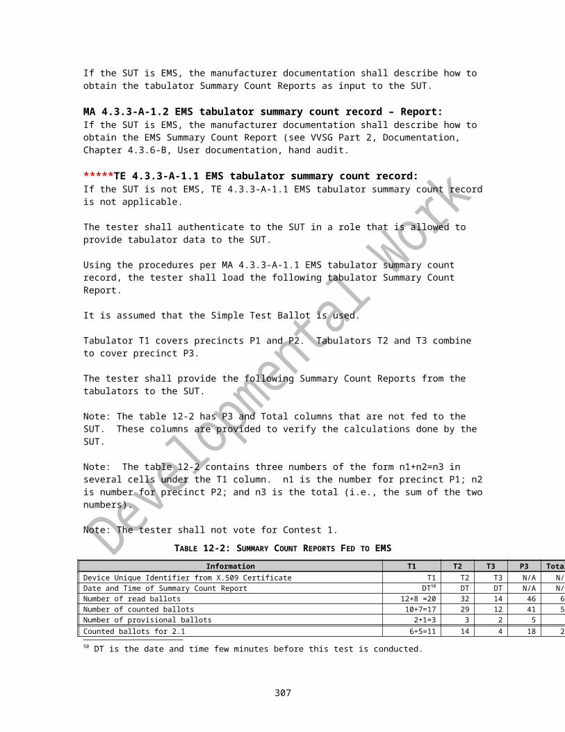
STS Security and Transparency SubcommitteeSUT System Under TestTDES Triple Data Encryption Standard (a symmetric data encryption algorithm)TDP Technical Data Package (see VVSG for further information)TE Tester ActivityTGDC Technical Guidelines Development CommitteeUPS Uninterrupted Power SupplyU.S. United StatesVVPAT Voter-verifiable Paper Audit TrailVVPR Voter-verifiable Paper RecordVVSG Voluntary Voting System Guidelines (see VVSG for further information)W3C World-Wide Web Consortium
307


![Introduction - interoperability.blob.core.windows.netMS-XLS]-180427.docx · Web viewversion of this technology, there are risks in relying on this preliminary documentation. To](https://static.fdocuments.in/doc/165x107/5d511c2888c993c3548b5ce5/introduction-ms-xls-180427docx-web-viewversion-of-this-technology-there-are.jpg)


![Introduction - interoperability.blob.core.windows.netMS-PPSAS]-180724.docx · Web viewversion of this technology, there are risks in relying on this preliminary documentation. To](https://static.fdocuments.in/doc/165x107/5d52129388c993a73d8b7132/introduction-ms-ppsas-180724docx-web-viewversion-of-this-technology-there.jpg)

