Test Report - RFL Alternators · The main difference between the Stamford alternator and the RFL...
20
1 Test Report Himoinsa HYW-17 T5 Three Phase Diesel Generator Radial Flux Laboratories Pty. Ltd. E-mail: [email protected] Web: http://www.rflalternators.com/ 2/7 Pritchard Pl, Peakhurst, NSW, 2210 Phone: +61 2 9584 9970 Mobile: +61 408 504 842
Transcript of Test Report - RFL Alternators · The main difference between the Stamford alternator and the RFL...

1
Test Report
Himoinsa HYW-17 T5 Three Phase Diesel Generator
Radial Flux Laboratories Pty. Ltd.
E-mail: [email protected]
Web: http://www.rflalternators.com/
2/7 Pritchard Pl,
Peakhurst, NSW, 2210
Phone: +61 2 9584 9970
Mobile: +61 408 504 842

2
Contents
RFL Alternator versus Stamford Alternator .............................................................................................................. 3
Technical Specifications ............................................................................................................................................ 4
Switch-over Procedure .............................................................................................................................................. 5
Physical Comparisons ................................................................................................................................................ 6
Test Procedure .......................................................................................................................................................... 8
Performance Test Results ......................................................................................................................................... 9
Motor Starting Test Results .................................................................................................................................... 11
Waveform Test Results ........................................................................................................................................... 14
Fuel Test Results ..................................................................................................................................................... 15
Performance Test Results with New RFL Speed controller fitted ........................................................................... 17
Conclusion ............................................................................................................................................................... 20
The information, data and drawings embodied in this test report are strictly confidential and are supplied on the understanding that
they will be held under RFL, Generator Power and Himoinsa, its management and board of directors. It cannot be used by,
disclosed to, or distributed to third parties without the above mentioned companies’’ consent.

3
RFL Alternator versus Stamford Alternator
A comparison on the Yanmar 4TNV88 Diesel Engine (Himoinsa HYW-17 Gen-Set)
The RFL Alternator RF-4 Series is a technologically advanced brushless single stator, single rotor permanent
magnet design. The combination of novel winding techniques with innovative rotor and stator design gives the RF
series significant advantage over current commercially available technologies.
The RF4 series alternators are designed to be compact and lightweight with high efficiency. All materials used in
construction are conventional, so as to minimize manufacturing cost whilst still providing the specified performance.
Its PM design and natural electronic regulation means that possible points of failure are kept to a minimum by
eliminating traditional brushes and AVRs.
The original Stamford PI044H Alternator was used as a comparison point for its similar high efficiency, brushless
design. Tests results of fuel economy, motor starting capabilities and other physical factors were compared and the
RFL alternator was found to be superior in most aspects.

4
Technical Specifications
Alternator Stamford PI044H RFL RF4-160-130-157
Type Brushless Alternator with Exciter PM Brushless Alternator
Poles 4 Poles 4 Poles
Phase 3 Phase 3 Phase
Frequency 50Hz 50Hz
RPM 1500 RPM 1500 RPM
Voltage Range 415 V 420 V
Apparent Power 17.6 kVA 20.7 kVA
Power Factor 0.8 0.8
Standby Power 16.0 kW 20.0 kW
Continuous Power 14.0 kW 17.0 kW
Regulation AVR Controlled + PM End No AVR
Stator Resistance 0.561 Ohms 0.275 Ohms
Bearing Single Single (removable cassette)
Enclosure IP23 IP23
Insulation Class H H
Length 555mm 300mm
Weight 107 kg 58 kg
Transients, Load Rejection 24.0 A
-11.0%, +13.0% -6.0% +0.0%
5
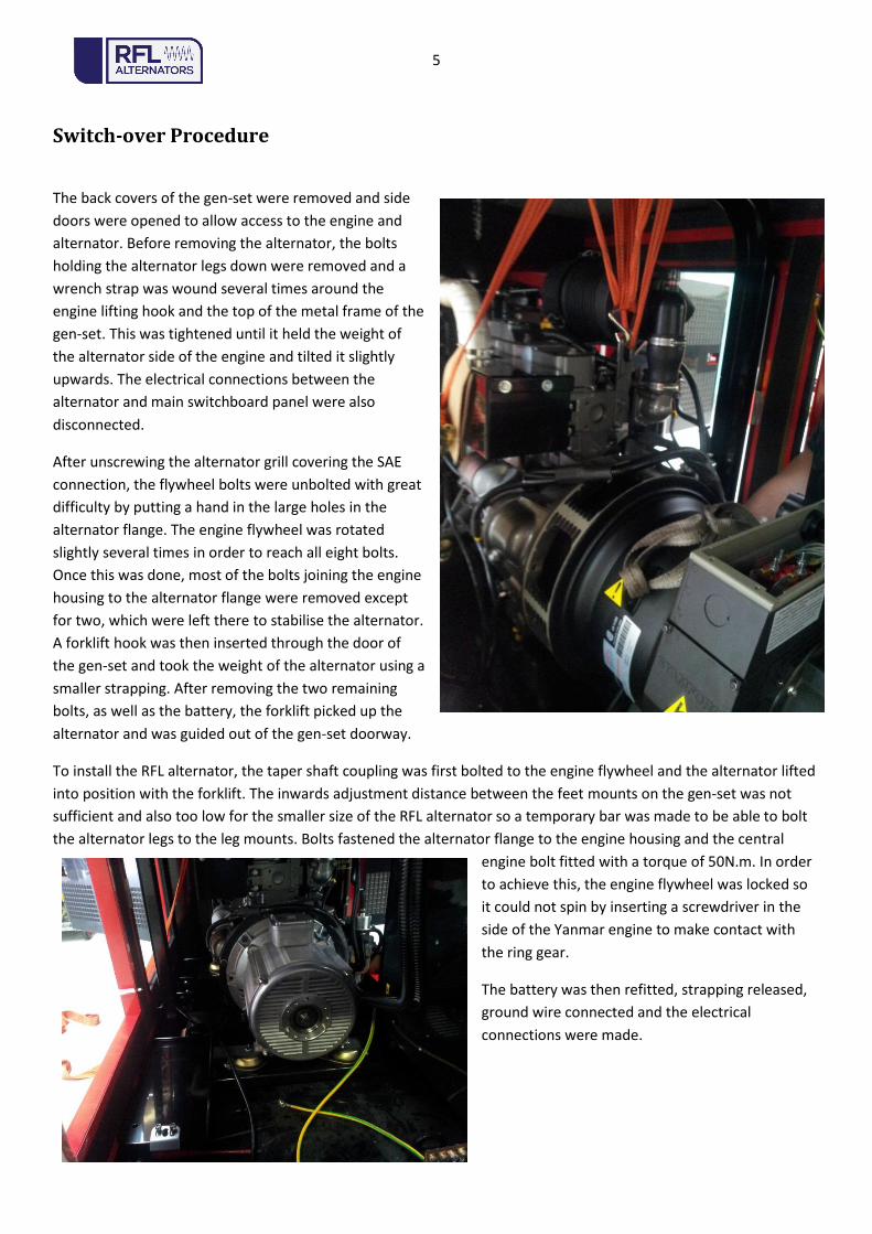
Switch-over Procedure
The back covers of the gen-set were removed and side
doors were opened to allow access to the engine and
alternator. Before removing the alternator, the bolts
holding the alternator legs down were removed and a
wrench strap was wound several times around the
engine lifting hook and the top of the metal frame of the
gen-set. This was tightened until it held the weight of
the alternator side of the engine and tilted it slightly
upwards. The electrical connections between the
alternator and main switchboard panel were also
disconnected.
After unscrewing the alternator grill covering the SAE
connection, the flywheel bolts were unbolted with great
difficulty by putting a hand in the large holes in the
alternator flange. The engine flywheel was rotated
slightly several times in order to reach all eight bolts.
Once this was done, most of the bolts joining the engine
housing to the alternator flange were removed except
for two, which were left there to stabilise the alternator.
A forklift hook was then inserted through the door of
the gen-set and took the weight of the alternator using a
smaller strapping. After removing the two remaining
bolts, as well as the battery, the forklift picked up the
alternator and was guided out of the gen-set doorway.
To install the RFL alternator, the taper shaft coupling was first bolted to the engine flywheel and the alternator lifted
into position with the forklift. The inwards adjustment distance between the feet mounts on the gen-set was not
sufficient and also too low for the smaller size of the RFL alternator so a temporary bar was made to be able to bolt
the alternator legs to the leg mounts. Bolts fastened the alternator flange to the engine housing and the central
engine bolt fitted with a torque of 50N.m. In order
to achieve this, the engine flywheel was locked so
it could not spin by inserting a screwdriver in the
side of the Yanmar engine to make contact with
the ring gear.
The battery was then refitted, strapping released,
ground wire connected and the electrical
connections were made.

6
Physical Comparisons
Figure 1 - Front view size comparison
Figure 2 - Top view size comparison

7
Alternator Comparison
Stamford RFL RFL % Reduction
Weight (Kg) 107 58 -45.79%
Resistance (Ohms) 0.561 0.257 -54.19%
Length(mm) 500 300 -40.00%
Efficiency 87% 95% +9.20%
Figure 3 - Stamford AVR Electronics Figure 4 - RFL electric terminals

8
Test Procedure
Tests were conducted on the HYW-17 T5 with the Stamford alternator to establish base line data using resistive load
and motor start loads. Temperature sensors were placed on the alternator and on the inside of the gen-set box.
These were named as; T1 Alternator Air In, T2 Alternator Air Out, T3 Alternator Case Temp, T4 Air inside Gen Set Box
. A HIOKI Power Analyser was used to measure volts, amps, Pf, watts and kVA. A Digital Oscilloscope (PicoScope
3425) was used to look at and record the wave forms and measure the transient voltages. A Pico USB TC-08, with K
type thermocouple, was used to measure and record the temperature.
Fuel usage was measured using a graduated glass column and a stop watch, scaled to measure in Litres/h. The fuel
tubes to the tank were removed and the input and output fuel pipes were re-routed to the glass column, so that fuel
volume could be measured.
The Stamford P .I044H1 alternator was then removed and replaced with the RFL RF4-160-130-157-3P alternator and
the same tests were repeated
Our original testing along with the data taken from the HIMOINSA Web site was used for the comparisons.
The maximum load testing point (SBY) was taken when the engine speed dropped to 49.8 Hz, and could be
maintained for 30 Minutes. The rated power (PRP) was taken when the engine speed dropped to 50.0Hz and could
be maintained for at least 1.5 Hours

9
20.86 Amp un-balanced load ( RFL Alt)
Volts Amps Volt Err
U 391.8 21.4 -23.2 -5.59%
V 422.8 0 7.8 1.88%
W 434 0 19 4.58%
U-N 233.16 21.4 -6.84 -2.85%
V-N 236.7 0 -3.3 -1.38%
W-N 250 0 10 4.17%
New Rating For HYW-17-T5
PRP 15.5 Kw
SBY 17.2 Kw
KVA 19.5 KVA
Current 27.1
Performance Test Results
When the Alternator was changed from the Stamford P.I044H1 to the RF4-160-130-157-3P RFL Alternator, the tests
showed an improvement of around 1,800 Watts extra from the engine at Continuous rating and 2,300 watts in
standby rating. The table below shows the new rating for the HYW-17-T5 when it is fitted with a RFL Alternator. The
testing was conducted at 17°C ambient.
Straight resistive loads:
The resistive load run showed that a new rating could be given for the HYW-17-T5
Calculated TemperatureGathered
Hou
rs
Tim
e (S
ec)
Pow
er (W
)
RMS
Vol
tage
(V)
RMS
Cur
rent
(A)
Freq
uenc
y (H
z)TH
D (%
)
PF KVA Vol
tage
Dro
p
Vol
tage
Dro
p %
Freq
uenc
y D
rop
(%)
Am
bian
t Tem
p
(T1)
Alt
Air
In
(T2)
Alt
Air
Out
(T3)
Alt
Cas
e Te
mp
(T4)
Air
Insi
de B
oxA
lt T
emp
Rise
Mag
Saf
ty
Com
men
ts
0.00 0 0 432.8 0 52.18 2.9/4.0 0 0.00% 0.00% 15 15 15 15 15 0 85
0.06 200 17,500 394 25.4 50 1.5/5.0 38.8 -8.96% -4.18% 15 19 25 38 15 19 75
0.11 400 17,660 392 25.7 49.95 1.5/5.08 40.8 -9.43% -4.27% 15 20 27 42 15 22 73
0.22 800 17,350 390.8 25.6 49.9 1.5/5.08 42 -9.70% -4.37% 15 22 32 53 16 31 68
0.33 1200 17,200 390 25.57 49.9 1.5/5.08 42.8 -9.89% -4.37% 15.7 24 37 61.7 17.6 37.7 63
0.44 1600 17,100 387.5 25.5 49.8 1.5/5.0 45.3 -10.47% -4.56% 16 23.6 40.2 66.8 17 43.2 59.8
0.46 1650 16,730 388 24.7 50 1.5/5.0 44.8 -10.35% -4.18% 16 24.3 41 68.1 17 43.8 59
1.25 4500 16,200 383.9 24.45 49.8 1.5/5.0 48.9 -11.30% -4.56% 17 27 52 80 17 53 48
1.28 4600 15,480 387 23 49.9 1.6/5.0 45.8 -10.58% -4.37% 17 28 51 81 17 53 49
1.49 5360 16,300 384 24.4 49.8 1.6/5.0 48.8 -11.28% -4.56% 17 27 50 80 18 53 50
1.53 5500 16,200 383 24.4 49.8 1.6/5.0 49.8 -11.51% -4.56% 17 27 49.8 80.8 17.5 53.8 50.2
1.58 5700 0 425 0 52.1 2.6/3.8 7.8 -1.80% -0.15% 17 27 49 81 18 54 51 Load Off
Temp After stablise stop
Load Down
Cont Rating
Load Down
Cont Rating
Max Rating (Standby)

10
Voltage regulation:
The main difference between the Stamford alternator and the RFL Alternator is in its voltage response under load.
The RFL alternator having a full PM rotor, is affected by 2 variables, load and engine speed. This is because the RFL
alternator does not have an AVR and the voltage is affected by the changes in engine RPM. In our testing the engine
speed dropped by around 4.5% from No load to full load. This is a 20V voltage drop due to the engine droop. The
voltage is also affected by alternator load; this is a further 5% drop, giving a further 20V droop. The voltage droop
between no load and engine full load is around 40V (10%). The RFL Alternator is manufactured to run at the high end
of the voltage range when the engine is under no load (430V). This gave it a voltage range between no load and full
load of 430V to 385V.
The Stamford maintains an almost constant voltage of (415 V) over the full load range, but has a much higher
transient on sudden load changes and during DOL motor start. The steady voltage regulation was +-1%, but the
transient voltage change with resistive load changes (No Load to Full load 24 amp), was 468 – 368. This is a range of
+13% to -11%. This was even greater with motor start (5.5 Kw 2 pole 3 phase) even with the PM End fitted, reaching
values of 260V to 478V which is a range of -36% + 15%.
The RFL alternator on the other hand was much better during DOL motor start (5.5Kw 2 pole 3 phase). The voltage
went from 380 to 432 -26% to +4.0%. At no time during any load changes did the upper voltage go above the 440
volts for normal line voltage supplies. On the other hand the Stamford alternator fitted with a PM end had an
overshoot significantly over 478V.
For appliances and sensitive electronic equipment, they are more likely to be damaged by over voltage spikes rather
than low voltage dips, as all equipment is designed to work over the normal electrical line voltage range (440V –
376V). The AU line voltage is 400V +10% to -6%. So despite the fact that the RFL alternator has a larger voltage
regulation range, it is less likely to cause any damage to equipment, and will run all motors and other equipment
normally.
Stamford Alternator 24 a Load with MP end RFL Alternator 25.5A load change
Resistive load transients

11
Motor Starting Test Results
4 types of motor start and loads were conducted
1. 1 Phase 2.2 kW motor start air compressor at full pressure
2. 3 Phase DOL 5.5 kW 2 pole, and 5.5 kW 2 pole + 5.5 Kw 4 Pole Together
3. 3 phase 9.2 kW 2 pole connected in star with full load on shaft
4. 3 phase 37 kW 2 pole motor started with a WEG VF drive
1 Phase 2.2 kW motor start of compressor at full pressure
The 1 phase motor was a Teco ML90L-2, 2.2 Kw. It was able to start a 2 cylinder reciprocating compressor at full tank
pressure of 90 PSI. The motor started normally with no hesitation. The line voltage wave forms for both the
Stamford with PM end and the RFL alternator are shown below. You can see that the RFL Alternator transient
voltage did not drop as far on motor start. The blue is the 3 phase line to line voltage and the red is the 1 phase
voltage line to neutral.
Stamford, 2.2 Kw Motor start RFL 2.2 Kw Motor Start
1 Phase volts at start = 182.3 V AC 1 Phase Volts at start = 192.0 V AC

12
3 Phase DOL 5.5 kW, 2 pole, and 5.5 kW 2 pole + 5.5 kW 4 Pole Together
The second test involved starting a 5.5 kW 3 Phase 2 pole Motor DOL and starting transient wave forms were
analysed. The start waveforms for the Stamford and the RFL alternators are shown below.
You can see that there was a larger drop in voltage and a substantial over shoot in voltage, with the Stamford
alternator. The Stamford with PM end alternator had a voltage drop of 36% and a voltage overshoot of 15%,
whereas the RFL alternator had only a 26% drop and a 4% overshoot. An even greater voltage transient was evident
with the starting of the 2 motors together
Stamford with PM End 5.5 kW DOL motor start RFL 5.5 kW DOL motor start Volts drop to 266.6V Transient 478.8V Volts Drop to 308.5V Transient 432.6 V
Stamford with PM End, 5.5 +5.5 kW DOL motor start RFL 5.5 + 5.5 kW DOL motor start Volts drop to 160.0V Transient 498.8V Volts Drop to 234.0V Transient 416.5 V

13
3 phase 9.2 kW 2 pole connected in star with full load on shaft
The final test involved starting a 9.2 kW 2 pole motor connected in Star to reduce the start current. The motor was
driving a load of 5.0 Kw at full speed (typical high inertia fan type load). The Stamford alternator did start the load
quicker but with a large voltage drop and a very high over voltage spike
Stamford with PM End, 9.2 kW DOL motor start RFL 9.2 kW star connection DOL motor start Volts Drop to 230.0V Transient 493.0V Volts drop to 275V Transient 434V

14
Waveform Test Results
VF Drives:
The RFL alternator was used to start and run a large AC induction motor (37 Kw 3 phase 2 pole), using WEG CFW-11
drive. The loads are shown below in the table. The WEG Drive was rated at 73 Amps 380V to 480V.
The 37 kW motor was started with a 16.8 kW load with no problems. The waveforms seen by the RFL Alternator
were rather distorted due to the high frequency chopping of the drive, but this did not affect the performance of
either the VF drive or the AC motor. As the RFL alternator has no electronics or diodes, the high frequency chopping
caused by the VF Drive cannot affect the alternator or cause failures. The same applies to other loads such as 3
phase MIG welders and battery chargers. The waveforms seen by the alternator are shown below.
No load waveform 16.89 kW waveform
Loads
Kw Amps Volts
0 0 426
2.2 3.14 437.5
8.94 13.4 410.3
12.76 19.7 398.6
15.35 23.99 390 PRP Continues rating
16.89 27.2 381.2
17.38 28.3 377.4 SBY Max Stand by loading
15
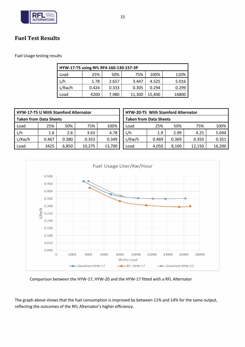
Fuel Test Results
Fuel Usage testing results
HYW-17-T5 using RFL RF4-160-130-157-3P
Load 25% 50% 75% 100% 110%
L/h 1.78 2.657 3.447 4.525 5.016
L/Kw/h 0.424 0.333 0.305 0.294 0.299
Load 4200 7,980 11,300 15,400 16800
HYW-20-T5 With Stamford Alternator
Taken from Data Sheets
Load 25% 50% 75% 100%
L/h 1.9 2.99 4.25 5.694
L/Kw/h 0.469 0.369 0.350 0.351
Load 4,050 8,100 12,150 16,200
Comparison between the HYW-17, HYW-20 and the HYW-17 fitted with a RFL Alternator
The graph above shows that the fuel consumption is improved by between 11% and 14% for the same output,
reflecting the outcomes of the RFL Alternator’s higher efficiency.
HYW-17-T5 U With Stamford Alternator
Taken from Data Sheets
Load 25% 50% 75% 100%
L/h 1.6 2.6 3.63 4.78
L/Kw/h 0.467 0.380 0.353 0.349
Load 3425 6,850 10,275 13,700

16
Fuel Cost savings Stamford changed to RFL
(Diesel Price $1.20/L)
Stamford RFL Saving Saving Saving $ Saving $ Saving $
Load % Load Kw L/h L/h L/h $/h 1000h 2500h 5000h
25% 4.05 1.9 1.78 0.12 $0.14 $144.00 $360.00 $720.00
50% 8.1 2.99 2.6973 0.2927 $0.35 $351.24 $878.10 $1,756.20
75% 12.2 4.26749 3.721 0.54649 $0.66 $655.79 $1,639.47 $3,278.94
100% 16.2 5.694 4.7628 0.9312 $1.12 $1,117.44 $2,793.60 $5,587.20
When the HYW-17 T5 has its alternator changed to a RFL Alternator, it can be rated at 20 KVA
The table above shows savings in $ for 1000h , 2500h, and 5000h run time for the average loads 25% to 100%. This is
based on the current diesel fuel cost of $1.20 per L. If the fuel cost is higher, the savings would also be higher.

17
Performance Test Results with New RFL Speed controller fitted
The HYW-17-T5 with the RFL RF4-160-130-157-3P alternator was fitted with aRFL Speed controller, and a
new set of load test results were recorded. The test result tables on the following page shows the new rating for the
HYW-17-T5 genset when it is fitted with a RFL Alternator and the RFL Speed controller. The testing was conducted at
30°C ambient temperature.
Figure 5 - Stepper Motor Throttle Control

18
RFL Fixed RPM Controll 09-12-2014 by Paul Lillington
Hou
rs
Run
Tim
e (M
in)
Pow
er (W
)
RMS
Vol
tage
(V)
RMS
Cur
rent
(A)
Freq
uenc
y (H
z)
THD
(%)
PF
KVA
Pow
er
Vol
tage
Dro
p
Vol
tage
Dro
p %
Freq
uenc
y ch
ange
(%)
Am
bian
t Tem
p
0 419.61 0 50.568 2.14 1 0 0 0.00% 1.14% 30
1,524 416.95 2.141 50.412 2.13 1 1,525 2.66 0.64% 0.82% 30
3,179 416.01 4.475 50.472 2.05 1 3,181 3.6 0.87% 0.94% 30
4,588 412.82 6.507 50.262 2.01 1 4,590 6.79 1.64% 0.52% 30
6,412 410.8 9.102 50.231 1.91 1 6,416 8.81 2.14% 0.46% 30
7,861 410.5 11.176 50.404 1.77 1 7,866 9.11 2.22% 0.81% 30
9,341 407.52 13.38 50.251 1.7 1 9,347 12.09 2.97% 0.50% 30
10,804 408.23 15.457 50.572 1.58 1 10,812 11.38 2.79% 1.14% 30
12,156 406.33 17.731 50.596 1.45 1 12,267 13.28 3.27% 1.19% 30
13,293 404.66 19.286 50.594 1.44 1 13,304 14.95 3.69% 1.19% 30
14,612 401.79 21.339 50.533 1.35 1 14,627 17.82 4.44% 1.07% 30
15,728 398.59 23.153 50.415 1.3 1 15,744 21.02 5.27% 0.83% 30
17,400 397.52 25.644 50.657 1.21 1 17,520 22.09 5.56% 1.31% 30
17,562 393.46 26.165 50.288 1.23 1 17,583 26.15 6.65% 0.58% 30
RFL Fixed Voltage control
Run
Hou
rs
Tim
e
Pow
er (W
)
RMS
Vol
tage
(V)
RMS
Cur
rent
(A)
Freq
uenc
y (H
z)
THD
(%)
PF
KVA
Pow
er
Vol
tage
Dro
p
Vol
tage
Dro
p %
Freq
uenc
y D
rop
(%)
Am
bian
t Tem
p
Adj
uste
d vo
ltag
e
Vol
t Dro
p C
orr
% V
olt D
rop
Cor
r
0.00 1.35 0 409.41 0.0 49.77 2.48 0.00 0.00 0.00% -0.47% 409.41 0.00 0.00%
0.01 1.36 1,472 409.8 2.1 49.97 2.40 1.00 -0.39 -0.10% -0.06% 409.8 -0.39 -0.10%
0.05 1.4 3,071 409.64 4.3 50.12 2.40 1.00 -0.23 -0.06% 0.23% 409.64 -0.23 -0.06%
0.05 1.4 4,517 409.41 6.4 50.26 2.30 1.00 0.00 0.00% 0.51% 409.41 0.00 0.00%
0.05 1.4 6,360 408.39 9.0 50.35 2.19 1.00 1.02 0.25% 0.70% 408.39 1.02 0.25%
0.06 1.41 7,812 408.92 11.0 50.61 2.09 1.00 0.49 0.12% 1.22% 408.92 0.49 0.12%
0.07 1.42 9,399 409.09 13.3 50.85 2.00 1.00 0.32 0.08% 1.69% 409.09 0.32 0.08%
0.10 1.45 10,839 408.96 15.3 51.06 1.93 1.00 0.45 0.11% 2.12% 408.96 0.45 0.11%
0.10 1.45 12,530 408.15 17.7 51.20 1.89 0.99 1.26 0.31% 2.41% 408.15 1.26 0.31%
0.10 1.45 13,478 407.04 19.2 51.30 1.78 1.00 2.37 0.58% 2.60% 407.04 2.37 0.58%
0.10 1.45 14,954 406.77 21.3 51.63 1.70 0.99 2.64 0.65% 3.25% 406.77 2.64 0.65%
-0.19 1.16 16,340 406.43 23.3 51.81 1.71 0.99 2.98 0.73% 3.62% 406.43 2.98 0.73%
0.11 1.46 16,878 406.12 24.1 51.92 1.70 0.99 3.29 0.81% 3.83% 406.12 3.29 0.81%
0.12 1.47 18,257 407.25 26.0 52.36 1.55 0.99 2.16 0.53% 4.72% 407.25 2.16 0.53%
0.16 1.51 18,180 406.83 25.9 52.42 1.54 0.99 2.58 0.63% 4.85% 406.83 2.58 0.63%
0.65 2 18,125 406.25 25.8 52.58 1.50 0.99 3.16 0.78% 5.15% 406.25 3.16 0.78%
0.75 2.1 18,123 406.22 25.8 52.78 1.47 0.99 3.19 0.79% 5.57% 406.22 3.19 0.79%
0.85 2.2 18,158 406.69 25.9 52.99 1.41 0.99 2.72 0.67% 5.98% 406.69 2.72 0.67%
0.89 2.24 18,143 406.32 25.9 53.01 1.41 0.99 3.09 0.76% 6.02% 21.7 KVA Rating 406.32 3.09 0.76%
0.90 2.25 16,869 406.04 24.1 52.69 1.55 0.99 3.37 0.83% 5.38% 20 KVA Rating 406.04 3.37 0.83%
1.00 2.35 16,847 405.99 24.0 52.74 1.52 0.99 3.42 0.84% 5.47% 20 KVA Rating 405.99 3.42 0.84%
1.04 2.39 0 408.35 0.0 50.30 2.48 0.99 1.06 0.26% 0.60% Load Off after run
Test results: Straight resistive loads with RFL Speed controller

19
As can be seen above, the only test results that maintains its output within the red envelope is the RFL Alternator
when fitted with the constant speed control. The envelope encasing the purple line is much smaller than that of the
mains power. This means that the RFL Alternator, with its much higher efficiency, better transient and motor
starting, when fitted with a constant speed control, will run any loads at their rated load, voltage, and frequency
without complications. The RFL speed controller is also able to maintain constant voltage similar to that of the
Stamford alternator. However, as its range falls outside of the mains supply regulation, it is not recommended.
Test result envelope of the HYW-17 T5 Gen set
The Red Envelope is the normal line supply guarantee from AusGrid, (Australian electricity supply authority) The Light Blue Lines represents the Stamford Alternator fitted to the HYW-17 T5 (Standard Speed control)
The Green line represents the RFL Alternator fitted to the HYW-17 T5 (Standard speed control) The Dark Blue line represents the RFL Alternator fitted to the HYW-17 T5 (With constant voltage control)
The Purple line represents the RFL Alternator fitted to the HYW-17 T5 (with constant speed control)

20
Conclusion
When the HIMONSA HYW-17-T5 gen set is fitted with the RFL Alternator, it lifts its performance very close to that of
the HYW-20-T5 Gen set. This is achieved while giving a reduction in overall weight and a potential reduction in
cabinet size. Changing the alternator in the HYW-17-T5, from the Stamford to a RFL RF-160-130-157-P3 alternator
would enable it to be rated at 19.5 kVA (HYW-19.5-T5) and achieve an 11% to 14% fuel saving over the current HYW-
20-T5, 20 kVA. Motor starting ability is comparable to the HYW-20-T5 20 kVA gen set fitted with a PM referenced
alternator.
The RFL Alternator’s no Load Voltage is proportional to the speed of the engine, and engine droop has an effect on
the output voltage. The 4.5% speed droop from no load to full load requires 5% extra voltage droop. The RFL
alternator has a nominal 5% voltage droop between no load and full load, so this gives a 10% voltage droop overall.
RFL Speed controller fitted:
When the new RFL Speed controller was fitted to the (HYW-17-T5) we were able to run the unit is two new modes,
fixed voltage control or fixed speed control.
For applications where the voltage is critical the fixed voltage control mode can keep the voltage within 1%, by
varying the frequency between 49.7Hz and 53 Hz over the full load range. Using the fixed frequency (RPM) control
mode the voltage dropped by 6% while the frequency stayed within 1%. This mode can be used when fixed
frequency is critical, and for parallel or grid connected operation. The only mode of operation that stayed within the
Ausgrid (supply authority) envelope was the RFL fixed frequency mode. With the RFL speed controller fitted, the gen-
set KVA rating was increased by up to 10%.
Cost Saving:
Replacing the Stamford alternator with the RFL alternator, could potentially reduce the cost of the HYW-20 to the
same cost as the HYW-17. Additionally operational costs savings of up 10% could also be recognised.
Advantages in extreme duty application:
The RF4-160-130-157-3P alternator has a special Dolphon CB1128 coating on both the winding and rotor. It is
specially manufactured to withstand the grit and salt on European roads. This also makes it suitable for marine use
and working in dusty environments where the dust is abrasive. The RFL Alternator can operate with no failures with
light salt spray in the intake air. The special bearing cassette is the only wearing component and can be replaced
without removing the alternator from the engine.