TEST REPORT IEC 62368-1 Audio/video, information and ... · (5.4.1.4, 6.2, 9.2.5 annex b.2)...
13
3 Test Report issued under the responsibility of: TEST REPORT IEC 62368-1 Audio/video, information and communication technology equipment Part 1: Safety requirements Report Number .............................. : E135494-A6007-CB-1 Date of issue.................................... : 2019-10-04 Total number of pages .................... : 70 Applicant’s name ........................... : TDK-LAMBDA UK LTD KINGSLEY AVE ILFRACOMBE EX34 8ES UNITED KINGDOM Address ........................................... : Name of Test Laboratory preparing the Report ...................... : UL International Germany GmbH Admiral-Rosendahl-Strasse 23, 63263 Neu-Isenburg (Zeppelinheim), Germany Test specification: Standard ......................................... : IEC 62368-1:2014 (Second Edition) Test procedure ............................... : CB Scheme Non-standard test method .............. : N/A Test Report Form No. ...................: IEC62368_1B Test Report Form(s) Originator ...... : UL(US) Master TRF..................................... : 2014-03 Copyright © 2014 Worldwide System for Conformity Testing and Certification of Electrotechnical Equipment and Components (IECEE), Geneva, Switzerland. All rights reserved. This publication may be reproduced in whole or in part for non-commercial purposes as long as the IECEE is acknowledged as copyright owner and source of the material. IECEE takes no responsibility for and will not assume liability for damages resulting from the reader's interpretation of the reproduced material due to its placement and context. If this Test Report Form is used by non-IECEE members, the IECEE/IEC logo and the reference to the CB Scheme procedure shall be removed. This report is not valid as a CB Test Report unless signed by an approved CB Testing Laboratory and appended to a CB Test Certificate issued by an NCB in accordance with IECEE 02. General disclaimer: The test results presented in this report relate only to the object tested. This report shall not be reproduced, except in full, without the written approval of the Issuing CB Testing Laboratory. The authenticity of this Test Report and its contents can be verified by contacting the NCB, responsible for this Test Report.
Transcript of TEST REPORT IEC 62368-1 Audio/video, information and ... · (5.4.1.4, 6.2, 9.2.5 annex b.2)...
3
Test Report issued under the responsibility of:
TEST REPORT
IEC 62368-1
Audio/video, information and communication technology equipment
Part 1: Safety requirements
Report Number .............................. : E135494-A6007-CB-1
Date of issue .................................... : 2019-10-04
Total number of pages .................... : 70
Applicant’s name ........................... : TDK-LAMBDA UK LTD
KINGSLEY AVE
ILFRACOMBE
EX34 8ES UNITED KINGDOM
Address ........................................... :
Name of Test Laboratory
preparing the Report ...................... :
UL International Germany GmbH
Admiral-Rosendahl-Strasse 23, 63263 Neu-Isenburg (Zeppelinheim), Germany
Test specification:
Standard ......................................... : IEC 62368-1:2014 (Second Edition)
Test procedure ............................... : CB Scheme
Non-standard test method .............. : N/A
Test Report Form No. ...................: IEC62368_1B
Test Report Form(s) Originator ...... : UL(US)
Master TRF ..................................... : 2014-03
Copyright © 2014 Worldwide System for Conformity Testing and Certification of Electrotechnical Equipment and Components (IECEE), Geneva, Switzerland. All rights reserved.
This publication may be reproduced in whole or in part for non-commercial purposes as long as the IECEE is acknowledged as copyright owner and source of the material. IECEE takes no responsibility for and will not assume liability for damages resulting from the reader's interpretation of the reproduced material due to its placement and context.
If this Test Report Form is used by non-IECEE members, the IECEE/IEC logo and the reference to the CB Scheme procedure shall be removed.
This report is not valid as a CB Test Report unless signed by an approved CB Testing Laboratory and appended to a CB Test Certificate issued by an NCB in accordance with IECEE 02.
General disclaimer:
The test results presented in this report relate only to the object tested. This report shall not be reproduced, except in full, without the written approval of the Issuing CB Testing Laboratory. The authenticity of this Test Report and its contents can be verified by contacting the NCB, responsible for this Test Report.

Issue Date: 2019-10-04 Page 2 of 70 Report Reference # E135494-A6007-CB-1
IEC62368_1B 3 2
Test Item description : AC-DC Power Supply
Trade Mark ................................................... : TDK Lambda
Manufacturer ................................................. : TDK-LAMBDA UK LTD
KINGSLEY AVE
ILFRACOMBE
EX34 8ES UNITED KINGDOM
Model/Type reference ................................... : CUS400M series
Unit product code : CUS400M-xxVx/yyyy
(see model differences for detail)
Ratings .......................................................... : INPUT: 100-240Vac, 47-440Hz, max 5.75A
Output:
CUS400M-12: 12Vdc 33.5A
CUS400M-24: 24Vdc 16.7A
(max 400W forced air cooling
max 250W natural convection)
Standby options:
board X2, X5: 5Vdc 2A
board X3, X6: 12Vdc 0,83A
(max 10W)
Testing procedure and testing location:
CB Testing Laboratory:
Testing location/ address ........................... : UL International Germany GmbH, Admiral-Rosendahl-Strasse 23, 63263 Neu-Isenburg (Zeppelinheim), Germany
Tested by (name + signature).............. : Piotr A. Bizunowicz / Project Handler
Approved by (name + signature) ......... : Dennis Butcher / Reviewer
Testing procedure: CTF Stage 1
Testing location/ address ............................ :
Tested by (name + signature).............. :
Approved by (name + signature) ......... :
Testing procedure: CTF Stage 2
Testing location/ address ............................ :
Tested by (name + signature).............. :

Issue Date: 2019-10-04 Page 3 of 70 Report Reference # E135494-A6007-CB-1
IEC62368_1B 3 3
Witnessed by (name + signature) ........ :
Approved by (name + signature) ......... :
Testing procedure: CTF Stage 3
Testing procedure: CTF Stage 4
Testing location/ address ............................ :
Tested by (name + signature).............. :
Witnessed by (name + signature) ........ :
Approved by (name + signature) ......... :
Supervised by (name + signature) ...... :
Issue Date: 2019-10-04 Page 4 of 70 Report Reference # E135494-A6007-CB-1
IEC62368_1B 8 0 4
List of Attachments (including a total number of pages in each attachment):
National Differences (30 pages)
Enclosures (53 pages)
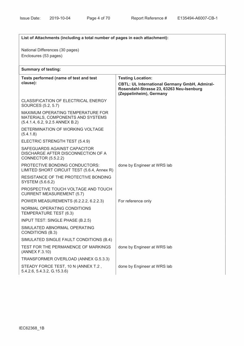
Summary of testing:
Tests performed (name of test and test clause):
Testing Location:
CBTL: UL International Germany GmbH, Admiral-Rosendahl-Strasse 23, 63263 Neu-Isenburg (Zeppelinheim), Germany
CLASSIFICATION OF ELECTRICAL ENERGY SOURCES (5.2, 5.7)
MAXIMUM OPERATING TEMPERATURE FOR MATERIALS, COMPONENTS AND SYSTEMS (5.4.1.4, 6.2, 9.2.5 ANNEX B.2)
DETERMINATION OF WORKING VOLTAGE (5.4.1.8)
ELECTRIC STRENGTH TEST (5.4.9)
SAFEGUARDS AGAINST CAPACITOR DISCHARGE AFTER DISCONNECTION OF A CONNECTOR (5.5.2.2)
PROTECTIVE BONDING CONDUCTORS: LIMITED SHORT CIRCUIT TEST (5.6.4, Annex R)
done by Engineer at WRS lab
RESISTANCE OF THE PROTECTIVE BONDING SYSTEM (5.6.6.2)
PROSPECTIVE TOUCH VOLTAGE AND TOUCH CURRENT MEASUREMENT (5.7)
POWER MEASUREMENTS (6.2.2.2, 6.2.2.3) For reference only
NORMAL OPERATING CONDITIONS TEMPERATURE TEST (6.3)
INPUT TEST: SINGLE PHASE (B.2.5)
SIMULATED ABNORMAL OPERATING CONDITIONS (B.3)
SIMULATED SINGLE FAULT CONDITIONS (B.4)
TEST FOR THE PERMANENCE OF MARKINGS (ANNEX F.3.10)
done by Engineer at WRS lab
TRANSFORMER OVERLOAD (ANNEX G.5.3.3)
STEADY FORCE TEST, 10 N (ANNEX T.2 , 5.4.2.6, 5.4.3.2, G.15.3.6)
done by Engineer at WRS lab

Issue Date: 2019-10-04 Page 5 of 70 Report Reference # E135494-A6007-CB-1
IEC62368_1B 8 0 5
Summary of compliance with National Differences:
List of countries addressed: AU,NZ, JP, EU Group Differences, US,CA
The product fulfils the requirements of: EN 62368-1:2014 + A11:2017

Issue Date: 2019-10-04 Page 6 of 70 Report Reference # E135494-A6007-CB-1
IEC62368_1B 8 0 6
Copy of marking plate:
The artwork below may be only a draft. The use of certification marks on a product must be authorized by the respective NCBs that own these marks.
Note: The above markings are the minimum requirements required by the safety lab. For the final production samples, the additional markings which do not give rise to misunderstanding may be added.

Issue Date: 2019-10-04 Page 7 of 70 Report Reference # E135494-A6007-CB-1
IEC62368_1B 8 0 7
TEST ITEM PARTICULARS:
Classification of use by Skilled person
Supply Connection AC Mains
Supply % Tolerance +10%/-10%
Supply Connection – Type For building-in: To be determined in End Product
Considered current rating of protective device as part
of building or equipment installation
20 A;
building;
Equipment mobility for building-in
Over voltage category (OVC) OVC II
Class of equipment Class I
Access location N/A
Pollution degree (PD) PD 2
Manufacturer’s specified maximum operating ambient
(°C)
70, with derating above 50
IP protection class IPX0
Power Systems TN
TT
IT - 230 V L-L
Altitude during operation (m) 5000m m
Altitude of test laboratory (m) 2000 m or less
Mass of equipment (kg) max. 1kg
POSSIBLE TEST CASE VERDICTS:
- test case does not apply to the test object................. : N/A
- test object does meet the requirement ...................... : P (Pass)
- test object does not meet the requirement ................ : F (Fail)
TESTING:
Date of receipt of test item ............................................ : 2019-07-03, 2019-07-12
Date (s) of performance of tests ................................... : 2019-08-08, 2019-08-30 to 2019-09-20, 2019-09-26
GENERAL REMARKS:
"(See Enclosure #)" refers to additional information appended to the report. "(See appended table)" refers to a table appended to the report. Throughout this report a comma / point is used as the decimal separator.
Manufacturer’s Declaration per sub-clause 4.2.5 of IECEE 02:

Issue Date: 2019-10-04 Page 8 of 70 Report Reference # E135494-A6007-CB-1
IEC62368_1B 8 0 8
The application for obtaining a CB Test Certificate includes more than one factory location and a declaration from the Manufacturer stating that the sample(s) submitted for evaluation is (are) representative of the products from each factory has been provided ............................................................... :
Yes
Not applicable
When differences exist; they shall be identified in the General product information section.
Name and address of factory (ies) .......................... : 1) PANYU TRIO MICROTRONICS CO LTD
SHIJI INDUSTRIAL ESTATE
DONGYONG
NANSHA
GUANGZHOU
GUANGDONG 511453 CHINA
2) TDK-LAMBDA UK LTD
KINGSLEY AVE
ILFRACOMBE
EX34 8ES UNITED KINGDOM
3) TDK-LAMBDA MALAYSIA SDN BHD
LOT 2 & 3, BATU 9 3/4 KAWASAN PERINDUSTRIAN BANDAR BARU JAYA GADING KUANTAN PAHANG
26070MY
MALAYSIA
GENERAL PRODUCT INFORMATION:
Report Summary
All applicable tests according to the referenced standard(s) have been carried out.
Product Description
Unit is open-type AC/DC Power supply for building-in
Model Differences
Unit Nomenclature for CUS400M range
Unit product code : CUS400M-xxVx/yyyy
Where:
xxVx = Channel 1 output voltage from within the output voltage adjustment range from the "Output Voltage Range"
yyyy = unit options from list of standard unit options below, or non-safety related model differences
List of Standard Unit Options (yyyy)
Case Options:
Blank = open frame with potted baseplate
B = with metal baseplate
C = with M3 threaded inserts for underside mounting
U = with U Chassis

Issue Date: 2019-10-04 Page 9 of 70 Report Reference # E135494-A6007-CB-1
IEC62368_1B 8 0 9
A = with U chassis and cover
F = with U chassis and top fan
Connector options:
Blank = JST connector
M = with Molex connector
N = with Alex connector
Fuse Options:
Blank = Dual fused
E = with single fuse in live line (dual fuse is standard), not available for DC input
Signal, standby options
X2 = option board 2: 5V 2.0A standby supply, remote on/off (enable), dc good, ac fail, remote sense
X3 = option board 3: 12V 0.83A standby supply, remote on/off (enable), dc good, ac fail, remote sense
X5 = option board 5: 5V 2.0A standby supply, remote on/off (inhibit), dc good, ac fail, remote sense
X6 = option board 6: 12V 0.83A standby supply, remote on/off (inhibit), dc good, ac fail, remote sense
Leakage current options:
S = Industrial Leakage <3.5mA for Class I, 60950-1 and 62368-1 only
blank = standard leakage <250µA
R = Reduced Leakage <150µA
T = Reduced Leakage <50µA
Examples:
CUS400M-24 open pcb with baseplate with dual fuses and standard features, 24V
CUS400M-24V5 as above with output set to 24.5V
CUS400M-12/U U chassis, 12V
CUS400M-15V25/FE U chassis, cover and fan, single fuse, 15.25V
Unit Product Code may be prefixed by K, SP and/or NS followed by / or -
For units with non-safety related changes eg. Reduced OVP, current limit etc.
Unit product code is followed by "-NNNNL", where N is a string of numbers which identifies the unique requirement. And L is a letter, starting with "A", which is incremented for any customer revision.
Example: CUS400M-24/FE-0001A
For non-standard units:
Prefix with "NS-". Follow by basic model type eg. CUS400M. Followed by "-NNNNL", where N is a string of numbers which identifies the non-standard requirement. L is a letter, starting with "A", which is incremented for any customer revision.
Example: NS-CUS400M-24-0001A
Refer to enclosures 7-01 and 7-02 for output parametres and de-rating information

Issue Date: 2019-10-04 Page 10 of 70 Report Reference # E135494-A6007-CB-1
IEC62368_1B 8 0 10
Additional application considerations – (Considerations used to test a component or sub-assembly) -
Potting is used for thermal performance only -- spacings and insulation comply with clause 5.4
models tested:
CUS400M-12-UX6 (highest output current)
CUS400M-24-UX5 (highest working voltage, most severe thermal effect)
Following components may require attention when unit is used in End Product with custom cooling or outside ratings:
L6: 120°C
L7: 120°C
TX1: 130°C
TX3: 130°C
C15: 125°C
C6: 125°C
C7: 125°C
Technical Considerations
· The product was submitted and evaluated for use at the maximum ambient temperature (Tma)
permitted by the manufacturer’s specification of : 70°C with derating above 50°C
· The product is intended for use on the following power systems : TN, TT, IT
· Considered current rating of protective device as part of the building installation (A) : 20
· Mains supply tolerance (%) or absolute mains supply values : +10%/-10%
· The equipment disconnect device is considered to be : determined in end Use Application
· The product was investigated to the following additional standards : EN 62368-1:2014, AS/NZS
62368.1:2018
· The following scope limitations apply to this test report and are confirmed by Applicant to be covered
separately. Additional evaluation and/or tests may be required when submitting this CB Report to a
National Certification Body (NCB) to obtain a national mark:
1) no EMC tests nor evaluation to EMC Directive 2004/108/EC and 2014/30/EU,
2) no evaluation to RoHS Directives 2002/95/EC, 2011/65/EU and (EU) 2016/585,
3) no evaluation to Council Recommendation 1999/519/EC nor 2006/25/EC,
4) only English version of markings and instructions provided and reviewed,
· Above 50°C the total output power and current ratings are both de-rated to ensure power curves are
met. Refer to Enclosures 7-01 for the De-rating curves.
Engineering Conditions of Acceptability
When installed in an end-product, consideration must be given to the following:
· The end-product Electric Strength Test is to be based upon a maximum working voltage of : Primary –
Earthed Dead Metal: 299 Vrms/ 571 Vpk; Primary-Secondary: 391 Vrms/ 620 Vpk
· The following output circuits are at ES1 energy levels : All outputs
· The following output circuits are at PS3 energy levels : All outputs
· The maximum investigated branch circuit rating is : 20 A
· The investigated Pollution Degree is : 2
· Proper bonding to the end-product main protective earthing termination is : Required

Issue Date: 2019-10-04 Page 11 of 70 Report Reference # E135494-A6007-CB-1
IEC62368_1B 8 0 11
· An investigation of the protective bonding terminals has : not been conducted (N.B. an investigation of
the PCB traces has been conducted in Annex R}
· The following input terminals/connectors must be connected to the end-product supply neutral : N
· The following end-product enclosures are required : Fire, Electrical, Mechanical
· The following magnetic devices (e.g. transformers or inductor) are provided with an OBJY2 insulation
system with the indicated rating greater than Class A (105°C) : XT1 class 155 (F), TX3 class 155 (F)
· The following components require special consideration during end-product Thermal (Heating) tests due
to the indicated maximum temperature measurements during component-level testing : See Additional
Information
· The maximum continuous power supply output (Watts) relied on forced air cooling from : For option F
only: 400W with fan as provided with product.
· The power supply was evaluated to be used at altitudes up to : 5000m

Issue Date: 2019-10-04 Page 12 of 70 Report Reference # E135494-A6007-CB-1
IEC62368_1B 1 12
ENERGY SOURCE IDENTIFICATION AND CLASSIFICATION TABLE:
(Note 1: Identify the following six (6) energy source forms based on the origin of the energy.) (Note 2: The identified classification e.g., ES2, TS1, should be with respect to its ability to cause pain or injury on the body or its ability to ignite a combustible material. Any energy source can be declared Class 3 as a worse case classification e.g. PS3, ES3.
Electrically-caused injury (Clause 5):
(Note: Identify type of source, list sub-assembly or circuit designation and corresponding energy source classification) Example: +5 V dc input ES1
Source of electrical energy Corresponding classification (ES)
Primary circuit ES3
Secondary circuit ES1
Electrically-caused fire (Clause 6):
(Note: List sub-assembly or circuit designation and corresponding energy source classification)
Example: Battery pack (maximum 85 watts): PS2
Source of power or PIS Corresponding classification (PS)
Primary circuit PS3, arcing PIS, resistive PIS
Secondary circuit main board (main output and optional fan output)
PS3, resistive PIS
Secondary circuit option board PS3 declared by client
Injury caused by hazardous substances (Clause 7)
(Note: Specify hazardous chemicals, whether produces ozone or other chemical construction not addressed as part of the component evaluation.) Example: Liquid in filled component Glycol
Source of hazardous substances Corresponding chemical
none identified n/a
Mechanically-caused injury (Clause 8)
(Note: List moving part(s), fan, special installations, etc. & corresponding MS classification based on Table 35.) Example: Wall mount unit MS2
Source of kinetic/mechanical energy Corresponding classification (MS)
Fan blades MS1
Thermal burn injury (Clause 9)
(Note: Identify the surface or support, and corresponding energy source classification based on type of part,
location, operating temperature and contact time in Table 38.)
Example: Hand-held scanner – thermoplastic enclosure TS1
Source of thermal energy Corresponding classification (TS)
Parts accessible during servicing TS3
Radiation (Clause 10)
(Note: List the types of radiation present in the product and the corresponding energy source classification.)
Example: DVD – Class 1 Laser Product RS1
Type of radiation Corresponding classification (RS)
none identified n/a

Issue Date: 2019-10-04 Page 13 of 70 Report Reference # E135494-A6007-CB-1
IEC62368_1B 1 13
ENERGY SOURCE DIAGRAM
Indicate which energy sources are included in the energy source diagram. Insert diagram below
ES PS MS TS RS