TEST REPORT EN 60065 Audio, Video and similar electronic ... · : Class I equipment P 3.1 A new...
40
SHENZHEN LCS COMPLIANCE TESTING LABORATORY LTD. REPORT NO: LCS120216090TS Page 1 of 40 TEST REPORT EN 60065 Audio, Video and similar electronic apparatus Report reference No. ......................... : LCS120216090TS Compiled by (+ signature) ................. : Kevin Lin Approved by (+ signature) ................. : Jackey Qiu Date of issue ...................................... : February 27, 2012 Contents ............................................. : 40 pages Testing laboratory Name .................................................. : Shenzhen LCS Compliance Testing Laboratory Ltd. Address .............................................. : Xingyuan Industrial Park, Tongda Road, Bao’an Blvd., Bao’an District, Shenzhen, Guangdong, China Testing location .................................. : Same as above Client Name... ………………………………..: Power Centre Limited Address………………………………..: Flat/Rm C, 15/F, Unionway Commercial Centre, 283 Queen’s Road Central, Hong kong, China Test specification Standard ............................................. : EN 60065: 2002+A1: 2006+A11: 2008+A2: 2010+A12: 2011 Test procedure .................................. : Compliance with EN 60065: 2002+A1: 2006+A11: 2008+A2: 2010+ A12: 2011 Non-standard test method ................. : N.A. Test item Description…….….………: DNG-2300 Trademark……………………..……….: N.A. Model and/or type reference……..…..: DNG-2300 Manufacturer ...................................... : Power Centre Limited Address .............................................. : Flat/Rm C, 15/F, Unionway Commercial Centre, 283 Queen’s Road Central, Hong kong, China Rating(s) ...........................................: 220-230V~, 50Hz, 36W, Class I
Transcript of TEST REPORT EN 60065 Audio, Video and similar electronic ... · : Class I equipment P 3.1 A new...
SHENZHEN LCS COMPLIANCE TESTING LABORATORY LTD. REPORT NO: LCS120216090TS
Page 1 of 40
TEST REPORT
EN 60065
Audio, Video and similar electronic apparatus
Report reference No. ......................... : LCS120216090TS
Compiled by (+ signature) ................. : Kevin Lin
Approved by (+ signature) ................. : Jackey Qiu
Date of issue ...................................... : February 27, 2012
Contents ............................................. : 40 pages
Testing laboratory
Name.................................................. : Shenzhen LCS Compliance Testing Laboratory Ltd.
Address .............................................. : Xingyuan Industrial Park, Tongda Road, Bao’an Blvd., Bao’an District, Shenzhen, Guangdong, China
Testing location .................................. : Same as above
Client
Name... ………………………………..: Power Centre Limited
Address………………………………..: Flat/Rm C, 15/F, Unionway Commercial Centre, 283 Queen’s Road Central, Hong kong, China
Test specification
Standard............................................. : EN 60065: 2002+A1: 2006+A11: 2008+A2: 2010+A12: 2011
Test procedure .................................. : Compliance with EN 60065: 2002+A1: 2006+A11: 2008+A2: 2010+ A12: 2011
Non-standard test method ................. : N.A.
Test item Description…….….………: DNG-2300
Trademark……………………..……….: N.A.
Model and/or type reference……..…..: DNG-2300
Manufacturer ...................................... : Power Centre Limited
Address .............................................. : Flat/Rm C, 15/F, Unionway Commercial Centre, 283 Queen’s Road Central, Hong kong, China
Rating(s) ...........................................: 220-230V~, 50Hz, 36W, Class I
Administrator
新建图章
Administrator
新建图章

SHENZHEN LCS COMPLIANCE TESTING LABORATORY LTD. REPORT NO: LCS120216090TS
Page 2of 40
Particulars: test item vs. test requirements
Equipment mobility .................................................... : Portable Apparatus
Operating condition....................................................... : Continuous operation
Class of equipment ....................................................... : Class I equipment
Mass of equipment (kg) ................................................ : 1.45Kg
Protection against ingress of water .............................. : IPX0
Test case verdicts
Test case does not apply to the test object.................. : N(N/A)
Test item does meet the requirement .......................... : P(Pass)
Test item does not meet the requirement .................... : F(Fail)
Testing
Date of receipt of test item ........................................... : February 15, 2012
Date(s) of performance of test...................................... : February 15, 2012 – February 27, 2012
General remarks This test report shall not be reproduced except in full without the written approval of the testing laboratory. The test results presented in this report relate only to the item tested. "(see remark #)" refers to a remark appended to the report. "(see appended table)" refers to a table appended to the report. Throughout this report a comma is used as the decimal separator. Remark:
1. The ambient temperature is 25.
2. The laboratory ambient for testing: 22.0-28.0, 60%-73%R.H.

SHENZHEN LCS COMPLIANCE TESTING LABORATORY LTD. REPORT NO: LCS120216090TS
Page 3of 40
Copy of marking plate
DNG-2300 Model : DNG-2300 Input: 220-230V~, 50Hz, 36W
Power Centre Limited Made In China

SHENZHEN LCS COMPLIANCE TESTING LABORATORY LTD. REPORT NO: LCS120216090TS
EN 60065
Clause Requirement – Test Result - Remark Verdict
Page 4of 40
3 GENERAL REQUIREMENTS P
Safety class of the apparatus ........................ : Class I equipment P
3.1 A new method of measurement is described in EN 50332-1, Sound system equipment: Headphones and earphones associated with portable audio equipment - Maximum sound pressure level measurement methodology and limit considerations - Part 1: General method for "one package equipment”, and in EN 50332-2, Sound system equipment: Headphones and earphones associated with portable audio equipment - Maximum sound pressure level measurement methodology and limit considerations - Part 2: Guidelines to associate sets with headphones coming from different manufacturers.
N
4 General test conditions P
4.1 Conduct of tests P
4.1.1 Tests according to this standard are type tests P
4.1.2 The sample or samples under test shall be representative of the apparatus the user would receive.
P
4.1.3 Unless otherwise specified, the tests are carried out under normal operating conditions at:
- an ambient temperature between 15 and 35
- a relative humidity of 75% maximum
Ambient temperature: 25
Relative humidity: 50%
P
4.1.4 Any position of intended use of the apparatus, normal ventilation not being impeded.
During normal operation tests, ventilation is not impeded
P
4.1.5 The characteristics of the supply source used during the tests shall not appreciably influence the test results.
Considering the influence, all tests are conducted at 0.9 times or/and 1.1 times of the rated supply voltage range.
P
4.1.6 Where relevant, a standard signal consisting of PINK NOISE, band-limited by a filter whose response conforms to that given in figure C.1 in annex C.
N

SHENZHEN LCS COMPLIANCE TESTING LABORATORY LTD. REPORT NO: LCS120216090TS
EN 60065
Clause Requirement – Test Result - Remark Verdict
Page 5of 40
4.1.7 The a.c. values given in this standard are r.m.s values, unless specified otherwise
P
4.2 Normal operating conditions See below. P
4.2.1 The apparatus is connected to a supply voltage of 0.9 times or 1.1 times of any rated supply voltage for which the apparatus is designed.
Heating test is conducted at 0.9 times and 1.1 times of the rated supply voltage, and the other tests are conducted at 1.1 times of the rated supply range.
P
4.2.2 Any position of controls which are accessible to the user for adjustment by hand
N
4.2.3 Any earth terminal and any protective earth of single-phase supply may be connected to either pole of the isolated supply source used during the test
P
4.2.4 For an audio amplifier: See below. P
The apparatus is operated in such a way as to deliver one-eighth of the non-clipped output power to the rated load impedance using the standard signal described in 4.1.6.
P
The most unfavorable rated load impedance of any output circuit is connected or not.
P
Organs or similar instruments which have a tone-generator unit are operated with any combination of two bass pedal keys
N
4.2.5 Load conditions for the motor are chosen which may occur during intended use for apparatus incorporating motors.
Apparatus not incorporation motors.
N
4.2.6 An apparatus supplying power to other apparatus is loaded to give its rated power or not loaded.
The unit is not this kind of equipments.
N
4.2.7 A supply apparatus to be used inside apparatus, for which it is intended exclusively, is tested within such apparatus after installation according to the manufacturer’s instruction for use.
Ditto. N
4.2.8 For citizen’s band apparatus, the rated load impedance is connected or not to the antenna terminal.
This apparatus is not a citizen’s band apparatus.
N
4.2.9 For antenna positioners This apparatus is not an antenna positioners.
N

SHENZHEN LCS COMPLIANCE TESTING LABORATORY LTD. REPORT NO: LCS120216090TS
EN 60065
Clause Requirement – Test Result - Remark Verdict
Page 6of 40
4.2.9.1 Movements and the resting periods for antenna positioners in combination with their control and supply apparatus.
This apparatus is not an antenna positioners.
N
4.2.9.2 The power supply unit shall be loaded in accordance with the marked output rating and operated with a duty cycle of 5 min on, and 15 min off for satellite antenna positioners consisting of a power supply and control unit.
This apparatus is not an satellite antenna positioners.
N
4.2.10 Apparatus designed to be supplied exclusively by a special supply apparatus shall be tested together with this special supply apparatus.
This apparatus need not to be supplied by a special supply apparatus.
N
4.2.11 Apparatus supplied by supply apparatus for general use shall be supplied by a test power supply according to table 2.
This apparatus is not supplied by a supply apparatus for general use.
N
4.2.12 Apparatus intended to be used with optional detachable legs or stands are tested with or without legs or stands fitted.
This apparatus is not used with detachable legs or stands.
N
4.3 Fault conditions See below. P
4.3.1 Short-circuit across clearances and creepage distances if they are less than the values specified in clause 13 for basic and supplementary insulation.
Clearances and creepage distances are exceeded the values specified in clause 13.
P
4.3.2 Short-circuit across parts of insulating material The insulation of the insulating materials comply with the requirements of 10.3.
P
4.3.3 Short-circuit or interruption of : Refer to clause 11 P
heaters of electronic tubes No electronic tubes N
insulation between heaters and cathodes of electronic tubes
N
spacings in electronic tubes, excluding picture tubes
N
semiconductor devices, one lead at a time interrupted or any two leads connected together in turn.
N
4.3.4 Short-circuit or disconnection of resistors, capacitors, windings, loudspeakers, optocouplers, varistors or non-linear passive components.
Refer to clause 11 P

SHENZHEN LCS COMPLIANCE TESTING LABORATORY LTD. REPORT NO: LCS120216090TS
EN 60065
Clause Requirement – Test Result - Remark Verdict
Page 7of 40
4.3.5 For apparatus containing an audio amplifier, using the standard signal to deliver the most unfavourable output power from zero up to the maximum attainable output power to the rated load impedance.
No audio amplifier N
4.3.6 Motors are stalled if this is possible. No motors. N
4.3.7 Motors, relay coils or the like, intended for short-time or intermittent operation, are operated continuously if this can occur during operation
No motors, relay or similar components.
N
4.3.8 The apparatus is connected simultaneously to alternative types of supply
N
4.3.9 Output terminals of apparatus supplying power to other apparatus are connected to the most unfavourable load impedance, including short circuit.
See appended table 11.1 N
4.3.10 Ventilation openings shall be covered. See appended table 11.1 P
4.3.11 The apparatus is tested with one or more batteries with both intended and revered polarity
There are no batteries in this apparatus.
N
4.3.12 The most unfavourable load impedance including short circuit is connected to the antenna terminal for citizen’s band apparatus.
This apparatus is not a citizen’s band apparatus.
N
4.3.13 Mains voltage setting device should be set at the most unfavourable position for apparatus provided with a voltage setting devices.
This apparatus not provided with a voltage setting devices.
N
4.3.13 The voltage setting device should be adjusted at any output voltage for apparatus supplied by a special apparatus with a voltage setting devices for the output voltage.
This apparatus is not Supplied by a special apparatus.
N
4.3.15 Apparatus which can be supplied by supply apparatus for general use shall be tested by using a test power supply as specified in table 1 step by step upwards.
This apparatus is not supplied by supply apparatus for general use
N
5 Marking and instructions P
General See below. P

SHENZHEN LCS COMPLIANCE TESTING LABORATORY LTD. REPORT NO: LCS120216090TS
EN 60065
Clause Requirement – Test Result - Remark Verdict
Page 8of 40
Easily discernible when ready for use Indelible and legible after rubbing test
Marking plates provided on the bottom of the enclosure. After rubbing test by water and petroleum spirit, the marking still easily discernible, indelible and legible.
P
Letter symbols comply with IEC 60027 Considered. P
Graphical symbols comply with IEC 60417 & and ISO 7000
P
The on-position and off-position of switch shall be indicated in accordance with 14.6.3
N
5.1 Identification and supply ratings P
Maker’s or responsible vendor’s name, trade mark or identification mark
See the label P
Model number or type reference DNG-2300 P
Symbol of Class II Class I equipment. N
Marking for apparatus designed for use in tropical climates
N
Symbol-nature of supply ~ P
Rated voltage (V) 220-230V~ P
Raged frequency 50Hz P
Power marking Rated power consumption is 36W.
P
5.2 Terminals P
The symbol of the protective earthing conductor
P
The symbol of hazardous live under normal condition
No hazardous live terminals N
Marking of output terminal for supply of other apparatus
No such terminal N
5.3 Symbol indicating a specific component of affect safety in circuit diagram
P
5.4 Instructions Instruction for use provided in English. Versions of other languages will be provided when national approval.
P
Instruction for installation or use See above. P

SHENZHEN LCS COMPLIANCE TESTING LABORATORY LTD. REPORT NO: LCS120216090TS
EN 60065
Clause Requirement – Test Result - Remark Verdict
Page 9of 40
Language of instruction English P
5.4.1 For main powered apparatus, instruction shall state the apparatus shall not be exposed to dripping or splashing
The instruction statement complies with the requirement.
P
A warning of the terminals having hazardous live
Not such terminal N
A warning for replaceable lithium battery No lithium battery N
Instructions for modem if fitted N Class I earth connection warning P Instructions for multimedia system connection See user manual. P
Special stability warning for fixed installation Test according to sub-clause 19.
N
Warning: battery exposure to heat N
Warning: protective film on CRT face N
5.4. 2 Disconnect device: plug/coupler or all-pole mains switch location, accessibility and markings
Appliance inlet as disconnect device
P
Instructions for permanently connected equipment
No permanently connected equipment.
N
6 Hazardous radiation N
6.1 Ionizing radiation N
Adequate protection against ionizing radiation N
Measure value of ionizing radiation in normal condition
N
Measure value of ionizing radiation under fault condition
N
6.2 Laser radiation No laser radiation N
Protection against laser radiation under normal condition and fault condition
N
Classification of laser radiation N
Measure value N
6.2.1 a) Under normal operating conditions, the apparatus shall meet approachable emission limits of Class1 as specified in IEC60825-1
N
b) If the apparatus comply with 6.2.1.a, the requirements mentioned under c) and d) do not apply.
N

SHENZHEN LCS COMPLIANCE TESTING LABORATORY LTD. REPORT NO: LCS120216090TS
EN 60065
Clause Requirement – Test Result - Remark Verdict
Page 10of 40
c) Adequate measures shall be taken to prevent the opening of any cover by hand giving access to laser radiation in excess of class 1 limits.
N
d) Mechanical safety interlock shall be fail-safe, or shall withstand a switching test of 50000 cycles of operation.
N
6.2.2 a) When the apparatus is operated under fault conditions as specified in 4.3, the approachable emission level shall be not higher than class 3A outside the wavelength range of 400nm to 700nm and not higher than five times the limit for class 1 within the wavelength range of 400nm to 700nm.
N
b) If the apparatus comply with 6.2.2.a, the requirements mentioned under c) and d) do not apply.
N
c) Adequate measures shall be taken to prevent the opening of any cover by hand giving access to laser radiation in excess of the limits given in 6.2.2.a.
N
d) Mechanical safety interlock shall be fail-safe, or shall withstand a switching test of 50000 cycles of operation.
N
7 Heating under normal operating conditions P
7.1 During intended use, no part of the apparatus shall attain an excessive temperature.
During intended use, no part of the apparatus shall attain an excessive temperature.
P
7.1.1 Temperature rise of accessible parts (See appended table) P
7.1.2 Temperature rise of parts providing electrical insulation, other than windings
Ditto. P
7.1.3 Temperature rise of support or mechanical barrier
No such parts. N
7.1.4 Temperature rise of windings (See appended table) P
7.1.5 Temperature rise of parts not subject to a limit under 7.1.1 to 7.1.4 inclusive
Ditto. P
7.2 Insulating material supporting parts consecutively connected to the mains carry a current exceeding 0.2A, shall be resistant to heat.
N

SHENZHEN LCS COMPLIANCE TESTING LABORATORY LTD. REPORT NO: LCS120216090TS
EN 60065
Clause Requirement – Test Result - Remark Verdict
Page 11of 40
8 Constructional requirements with regard to the protection against electric
shock P
8.1 Conductive parts, covered only by lacquer, solvent -based enamel, ordinary paper, untreated textile, oxide films or beads are considered to be bare.
Considered. P
8.2 No shock hazard when changing voltage setting device, fuse-links or handling drawers etc.
P
8.3 Insulation of hazardous live parts not provided by hygroscopic materials.
No hygroscopic materials used.
P
8.4 There should be no risk of an electric shock from accessible parts or from those parts rendered accessible .
N
8.5 Class I apparatus P
Basic insulation between hazardous live parts and earthed accessible parts
Ditto. P
Capacitors bridging basic insulation complying with 14.2.1a
Ditto. P
Basic insulation bridged by components complying with 14.3.4.3
Ditto. P
8.6 Class II apparatus and Class II constructions within Class II equipment
N
Reinforced or double insulation between hazardous live parts and accessible parts
N
Components bridging reinforced or double insulation complying with 14.1 a) or 14.3
N
Basic and supplementary insulation each being bridged by a capacitor complying with 14.2.1 a)
No such capacitors are provided.
N
Reinforced or double insulation being bridged with 2 capacitors in series complying with 14.2.1 a)
Ditto. N
Reinforced or double insulation being bridged with a single capacitor complying with 14.2.1 b)
Ditto N
8.7 Basic insulation between parts at 35 V to 71 V (peak) a.c. or 60 V to 120 V d.c. and accessible parts
Class I equipment. P

SHENZHEN LCS COMPLIANCE TESTING LABORATORY LTD. REPORT NO: LCS120216090TS
EN 60065
Clause Requirement – Test Result - Remark Verdict
Page 12of 40
Reinforced or double insulation between circuits operating at voltages between 35 V and 71 V (peak) a.c. or between 60 V and 120 V d.c. and hazardous live parts at higher voltage
N
Separation by Class II isolating transformer See clause 14.3.2. N
Separation by Class I isolating transformer N
Separation by earthed conductive part P
8.8 Basic or supplementary insulation ≥0.4mm Class I equipment. P
Reinforced insulation≥0.4mm Ditto. P
Thin sheet insulation Incorporated in Transformer. P
Basic or supplementary insulation, at least two layers, each meeting 10.3
N
Basic or supplementary insulation, three layers any two of which meet 10.3
Insulating tape of transformer P
Reinforced insulation, two layers each of which meet 10.3
N
Reinforced insulation, three layers any two which meet 10.3
P
8.9 Adequate insulation between internal hazardous live conductors and accessible parts
All internal wires with only basic insulation are routed so that they are not close any live bare components.
P
Adequate insulation between internal hazardous live parts and conductors connected to accessible parts
Class I equipment. N
8.10 In class II apparatus, double insulation shall be provided between:
Class I equipment. N
accessible parts and conductors in wires or cables conductively connected to the mains
N
conductors in wires or cables connected to accessible conductive parts and parts conductively connected to the mains
Ditto. N
8.11 Detaching of wires Supply cord P
No undue reduction of creepage of clearance distances if wires become detached
P
Vibration test carried out P

SHENZHEN LCS COMPLIANCE TESTING LABORATORY LTD. REPORT NO: LCS120216090TS
EN 60065
Clause Requirement – Test Result - Remark Verdict
Page 13of 40
8.12 Adequate cross-sectional area of internal wiring to mains socket-outlets.
3X0.75mm2 P
8.13 Adequate fastening of windows, lenses, lamp covers etc. (pull test 20N for 10s)
Detachable plug N
8.14 Adequate fastening of covers (pull test 50N, for 10 s)
N
8.15 No risk of damage to the insulation of internal wiring due to not hot parts or sharp edges
Internal wiring away from sharp edges, moving parts and not to contact parts exceeding the permissible temperature.
P
8.16 Only special supply equipment can be used N
8.17 Requirements for insulated winding wires for use without additional interleaved insulation
No insulated winding wires for use without additional interleaved insulation.
N
8.18 Endurance test for wound components with insulated winding wires without additional interleaved insulation.
Ditto. N
Heat run --
Vibration test --
Moisture treatment --
Measurements --
8.19 Disconnection from the mains P
8.19.1 Disconnect device The appliance inlet as disconnect device
P
All-pole switch or circuit breaker with >3mm contact separation
N
8.19.2 Mains switch ON indication, main switch is used as a disconnect device.
P
8.20 Switch not fitted in the mains cord P
8.21 Bridging components comply with clause 14 No such components. N 9 Electric shock hazard under normal operating conditions P
9.1 Testing on outside --
9.1.1 General All secondary terminals are below 60Vdc. (See appended table)
P

SHENZHEN LCS COMPLIANCE TESTING LABORATORY LTD. REPORT NO: LCS120216090TS
EN 60065
Clause Requirement – Test Result - Remark Verdict
Page 14of 40
9.1.1.1 Determination of hazardous live parts P
Touch current measured from terminal devices using the network in Annex D
See the appended table P
Discharge not exceeding 45 uC --
Energy of discharge not exceeding 350 mJ --
9.1.1.2 Determination of accessible parts P
9.1.2 No hazardous live shafts of knobs, handlers or levers
P
9.1.3 Ventilation holes tested by means of 4 mm x 100 mm test pin
No access to any parts bearing hazardous voltage.
P
9.1.4 Terminal devices tested with 1 mm x 20 mm test pin (10 N); test probe D of IEC 61 032
P
9.1.5 Pre-set controls tested with 2 mm x 100 mm test pin (10 N); test probe C of IEC 61 032
P
9.1.6 No shock hazard due to stored charge on withdrawal of the mains plug; voltage (V) after 2 s
N
If C is not greater than 0.1 μF no test needed --
9.1.7 Enclosure sufficiently resistant to external force
See below. P
Test probe 11 of IEC 61 032 for 10 s (50N) 50 N force applied to rear enclosure, no hazard.
P
Test hook of fig.4 for 10s (20N) 20 N force directed outwards, is applied for 10 s at all points where this is possible, no hazard.
P
30 mm diameter test tool for 5 s (100 or 250N) 100N P
9.2 No hazard after removing a cover by hand P 10 Insulation requirements P
10.1 Insulation resistance (MΩ) at least a 2 MΩ min. after surge test for basic and 4 MΩ min. for reinforced insulation
After the test, the tested insulation complied with the requirement of clause 10.3
P
10.2 Humidity treatment 48 h or 120 h At 93% RH., 25 , 48hours. P
10.3.1 Insulation material of live parts be adequate to resistant to electric shock
(See appended table) P

SHENZHEN LCS COMPLIANCE TESTING LABORATORY LTD. REPORT NO: LCS120216090TS
EN 60065
Clause Requirement – Test Result - Remark Verdict
Page 15of 40
10.3.2 The insulation listed in table 5 shall be tested for insulation resistance and for dielectric strength.
(See appended table) P
11 Fault conditions P
11.1 No shock hazard under fault conditions The voltage of the audio connectors did not exceed the specified voltage. (see appended table)
P
11.2 Heating under fault condition During fault conditions, no fire propagated beyond the equipment.
P
11.2.1 Measurement of temperature rises (See appended table) P
11.2.2 Temperature rise of accessible parts (See appended table) P
11.2.3 Temperature rise of parts, other than windings, providing electrical insulation.
(See appended table) P
Temperature rise of printed circuit boards (PCB) exceeding the limits of Table 2 by max. 100 K for max. 5 min
N
a) Temperature rise of printed circuit boards (PCB) to 20.3.1, exceeding the limits of Table 2 by not more than 100 K for an area not greater than 2 cm²
N
b) Temperature rise of printed circuit boards (PCB) to 20.3.1 up to 300 K for an area not greater than 2 cm² for a maximum of 5 min
N
Meets all the special conditions if conductors on printed circuit boards are interrupted
N
11.2.4 Temperature rise of parts acting as a support or a mechanical barrier
No such parts, see 7.1.3 N
11.2.5 Temperature rise of windings (See appended table) P
11.2.6 Temperature rise of other parts not subject to the limits of 11.2.1 to 11.2.5
(See appended table) P
12 Mechanical strength P
12.1 Adequate mechanical strength P
12.1.1 Bump test for apparatus with a mass exceeding 7Kg
Mass: 1.45kg<7kg N

SHENZHEN LCS COMPLIANCE TESTING LABORATORY LTD. REPORT NO: LCS120216090TS
EN 60065
Clause Requirement – Test Result - Remark Verdict
Page 16of 40
12.1.2 Vibration test (Amplitude 0.35 mm, Frequency range 10Hz, 55Hz, 10Hz, Sweep rate 1 octave/min)
(See appended table) P
12.1.3 Impact test (The apparatus is subjected to three blows from a spring-operated impact hammer, applied with an impact of 0.5J to energy point of the exterior likely to be weak).
0.5 J, 3 times (After tested, no damaged and EUT can withstand the dielectric strength test as specified in 10.3).
P
Steel ball test 3.5 J, 1 time (After tested, no damaged and EUT can withstand the dielectric strength test as specified in 10.3).
P
12.1.4 Drop test for portable apparatus having where mass < 7 kg
No damager P
12.1.5 Stress relief test Metal enclosure N
12.2 Fixing of knobs, push buttons, keys and levers Knobs and push buttons are fastened that their use did not impair the protection against electric shock.
P
12.3 Remote controls with hazardous live parts Remote control has no hazardous live part.
N
12.4 Drawers (pull test 50 N, 10 s) P
12.5 Antenna coaxial withstand mechanical stresses
No antenna coaxial N
Endurance test --
Impact test --
Torque test --
12.6 Telescoping or rod antennas construction No such construction N
12.6.1 Telescoping or rod antennas securement Ditto. N 13 Clearances and creepage distances P
13.1 General See 13.2, 13.3 and 13.4. P
13.2 Determination of operating voltage Unit was connected to a 220-230V (maximum) power.
P
13.3 Clearances See below. P
13.3.1 General Annex and minimum clearances considered.
P

SHENZHEN LCS COMPLIANCE TESTING LABORATORY LTD. REPORT NO: LCS120216090TS
EN 60065
Clause Requirement – Test Result - Remark Verdict
Page 17of 40
13.3.2 Clearances in circuits conductively connected to the mains
(See appended table) P
13.3.3 Clearances in circuits not conductively connected to the mains
(See appended table) P
13.4 Creepage distances (See appended table) P
CTI tests CTI rating for all materials of min. 100.
P
13.5 Printed boards See below P
13.5.1 The minimum clearances and creepage The PCB complied with the pull-off and peel strength requirements of IEC 60249-2 are given in figure 10.
P
13.5.2 Type B coated printed circuit boards complying with IEC 60664-3 (basic insulation only)
Printed boards inside this apparatus are not type B coated printed boards.
N
13.6 Jointed insulation No such construction. N
13.7 Enclosed, enveloped or hermitically sealed parts: clearances and creepage distances to table 12
No such construction. N
13.8 Parts filled with insulating compound, meeting the requirements of 8.8
No such parts. N
14 Components P
14.1 Resistors No resistors short-circuiting or disconnected of which would cause an infringement of the requirement.
N
a) Resistors between hazardous live parts and accessible metal parts
No such resistors. N
b) Resistors, other than between hazardous live parts and accessible parts
Ditto. N
b) Resistors separately approved N
14.2 Capacitors and RC-units X-capacitor and Y-capacitor approved by VDE
P
Capacitors separately approved --
14.2.1 a) Sub-class Y2 or Y4 capacitors or RC-units withstand the tests as specified in IEC60384-14, table II
No such components N

SHENZHEN LCS COMPLIANCE TESTING LABORATORY LTD. REPORT NO: LCS120216090TS
EN 60065
Clause Requirement – Test Result - Remark Verdict
Page 18of 40
b) Sub-class Y1 or Y2 capacitors or RC-units withstand the tests as specified in IEC60384-14, table II
N
14.2.2 X-capacitors withstand test for Sub-class X1 or X2
N
14.2.3 Capacitors operating at mains frequency but not connected to the mains: tests for X2
N
14.2.4 Intentionally kept free for future requirements for capacitors or RC-units others than those mentioned in 14.2.1 to 14.2.3
See above. N
14.2.5 Capacitors with volume exceeding 1750 mm³, where short-circuit current exceeds 0,2 A: compliance with IEC60384-1, 4.38 category B or better
The enclosure of ripple capacitor is made by metal.
N
Capacitors with volume exceeding 1750 mm³, mounted closer to a potential ignition source than table 5 permits: compliance with IEC 60 384-1, 4.38 category B or better
Ditto. N
Shielded by a barrier to FV 0 or metal Ditto. N
14.3 Inductors and windings P
14.3.1 Transformers and inductors marked with manufacturer's name and type
See the table 14 P
Transformers and inductors separately approved
N
14.3.2 General See below. P
Isolating transformers shall comply with 14.3.3 and 14.3.4.1 or 14.3.4.2 and 14.3.5.1 or 14.3.5.2
Class II transformer. P
Separating transformers shall comply with 14.3.3 and 14.3.4.03and 14.3.5.1 or 14.3.5.2
N
14.3.3 Constructional requirements P
14.3.3.1 Clearances and creepage distances of all windings shall comply with the requirement of clause 13.
See appended table 13.1. P
14.3.3.2 Designs with more than one winding The input and output windings shall be electrically separated from each other.
An insulation barrier consisting of an uncemented pushed-on partition wall was used.
P
14.3.4 Separation between windings See below. P
14.3.4.1 Windings of class II construction P

SHENZHEN LCS COMPLIANCE TESTING LABORATORY LTD. REPORT NO: LCS120216090TS
EN 60065
Clause Requirement – Test Result - Remark Verdict
Page 19of 40
14.3.4.2 Windings of class I construction N
14.3.4.3 Windings of separating construction N
14.3.5 Insulation between hazardous live parts and accessible parts
P
14.3.5.1 Windings of class II construction P
14.3.5.2 Windings of class I construction N
14.4 High voltage components N
High-voltage components and assemblies: U > 4 kV (peak) separately approved
--
Component meets category FV 1 of IEC 60 707 --
14.4.1 High voltage transformers and multipliers tested as part of the submission
N
14.5 Protective devices P
Protective devices used within their ratings See 14.5.2.1. P
External clearance and creepage distances appropriate for the voltage across the device when opened
N
14.5.1.1 a) Thermal cut-outs separately approved No thermal cut-out used. N
b) Thermal cut-outs tested as part of the submission
N
14.5.1.2 a) Thermal links separately approved N
b) Thermal links tested as part of the submission
N
14.5.1.3 Thermal devices resettable by soldering No such components. N
14.5.2.1 Fuse-links in the mains circuit according to IEC 60 127
VDE approved fuse used P
14.5.2.2 Correct marking of fuse-links adjacent to holder P
14.5.2.3 Not possible to connect fuses in parallel Not used. N
14.5.2.4 Not possible to touch hazardous live parts when replacing fuse-links without the use of a tool
See 14.5.2.1 N
14.5.3 PTC-S thermistors comply with IEC 60 738 No PTC-S Thermistors N
PTC-S devices (15 W) category FV 1 or better Ditto. --
14.5.4 Circuit protectors have adequate breaking capacity and their position is correctly marked
Not such protectors used. N

SHENZHEN LCS COMPLIANCE TESTING LABORATORY LTD. REPORT NO: LCS120216090TS
EN 60065
Clause Requirement – Test Result - Remark Verdict
Page 20of 40
14.6 Switches VDE approved manually operated mechanical switch used.
P
14.6.1 a) Separate testing to IEC 61058 including: 10 000 operations Normal pollution suitability Resistance to heat and fire level 3 And V-0 compliance with annex G, G.1.1
N
b) Tested in the apparatus: N
Switch controlling > 0.2A with open contact voltage > 35 V (peak)/24 V dc complying with 14.6.3, 14.6.4 and V-0 in annex G, G.1.1
N
Switch controlling > 0.2A with open contact voltage < 35 V (peak)/24 V dc complying with 14.6.3 and V-0 in annex G, G.1.1
N
Switch controlling < 0.2A with open contact voltage > 35 V (peak)/24 V dc complying with 14.6.4 and V-0 in annex G, G.1.1
N
14.6.2 Switch tested to 14.6.1 b) constructed to EN 61058-1 subclause 13.1 and has making/breaking action independent of speed of actuation
N
14.6.3 Switch tested to 14.6.1 b) compliant with EN 61058-1 subclause 16.2.2 d) and m) not attaining excessive temperatures in use
N
14.6.4 Switch tested to 14.6.1 b) has adequate dielectric strength
N
14.6.5 Mains switch controlling mains socket outlets additional tests to IEC 60058-1
N
Socket outlet current marking correct N
14.7 Safety interlocks No safety interlocks used. N
Safety interlocks to 2.8 of IEC 60 950 N
14.8 Voltage setting devices Apparatus is designed for rated rating, no voltage setting device used.
N
Voltage setting device not likely to be changed accidentally
N
14.9 Motors No motors used. N
14.9.1 Endurance test on motors N
Motor start test N

SHENZHEN LCS COMPLIANCE TESTING LABORATORY LTD. REPORT NO: LCS120216090TS
EN 60065
Clause Requirement – Test Result - Remark Verdict
Page 21of 40
Dielectric strength test N
14.9.2 Not adversely affected by oil or grease etc. N
14.9.3 Protection against moving parts N
14.9.4 Motors with phase-shifting capacitors, three-phase motors and series motors meet Cl. B.8, B.9 and B.10 of IEC 60 950, Annex B
N
14.10 Batteries No battery used. N
14.10.1 Batteries mounted with no risk of accumulation of flammable gases
N
14.10.2 No possibility of recharging non-rechargeable batteries
N
14.10.3 Recharging currents and times within manufacturers limits
N
Lithium batteries discharge and reverse currents within the manufacturers limits
N
14.10.4 Battery mould stress relief N
14.10.5 Battery drop test N
14.11 Optocouplers Aprroved by VDE P
Optocouplers comply with Cl. 8 N
Internal and external dimensions to 13.1.1 N
14.12 Surge suppression varistors No such component N
Comply with IEC 61051-2 N
Not connected between mains and accessible parts except for earthed parts of permanently connected apparatus
N
Complies with the current pulse, fire hazard and thermal stress requirements of 14.12
N
15 Terminals P
15.1.1 Mains plug, appliance inlet, interconnection couplers and mains socket-outlet meet the appropriate standard
The appliance inlet, plug and cord complies with the appropriate component standard.
P
15.1.2 Connectors for antenna, earth, audio, video or data
P
No risk of insertion in mains socket-outlets P

SHENZHEN LCS COMPLIANCE TESTING LABORATORY LTD. REPORT NO: LCS120216090TS
EN 60065
Clause Requirement – Test Result - Remark Verdict
Page 22of 40
No risk of insertion into audio or video: outlets marked with the symbol of 5.2
N
15.1.3 Output terminals of AC adaptors or similar devices not compatible with household mains socket-outlets
N
15.2 Provision for protective earthing P
Accessible conductive parts of Class I equipment reliably connected to earth terminal, within equipment
P
Class I supply equipment with non-hazardous live output voltage: output circuit not connected to earth
P
Protective earth conductors correctly coloured P
Equipment with non-detachable mains cord provided with separate protective earth terminal near mains input
P
Protective earth terminal resistant to corrosion P
Earth resistance ≤0,1 P
15.3 Terminals for external flexible cords and for permanent connection to the mains supply
Apparatus is not designed for permanent connection.
N
15.3.1 Adequate terminals for connection of permanent wiring
N
15.3.2 Reliable connection of non-detachable cords N
not soldered to conductors of a printed circuit board
N
adequate clearances and creepage distances between connections should a wire break away
N
wire secured by additional means to the conductor
N
15.3.3 Screws and nuts clamping conductors have adequate threads: ISO 261, ISO 262 or similar
N
15.3.4 Soldered conductors wrapped around terminal prior to soldering or held in place by additional means
N
Clamping of conductor and insulation if not soldered or held by screws
N
15.3.5 Terminals allow connection of appropriate cross-sectional area of conductors, for the rated current of the equipment
N

SHENZHEN LCS COMPLIANCE TESTING LABORATORY LTD. REPORT NO: LCS120216090TS
EN 60065
Clause Requirement – Test Result - Remark Verdict
Page 23of 40
15.3.6 Terminals to 15.3.3 have sizes required by Table 8
N
15.3.7 Terminals clamp conductors between metal and have adequate pressure
N
Terminals designed to avoid conductor slipping out when tightened or loosened
N
Terminals adequately fixed to avoid loosening when the clamping is tightened or loosened and stress on internal wiring is avoided
N
15.3.8 Terminals carrying a current more than 0,2 A: contact pressure not transmitted by insulating material except ceramic
N
15.3.9 Termination of non-detachable cords: wires terminated near to each other
P
15.4 Devices forming a part of the mains plug P
15.4.1 No undue strain on mains socket-outlets N
15.4.2 Device complies with standard for dimensions of mains plugs
P
15.4.3 Device has adequate mechanical strength (tests a,b,c)
P
16 External flexible cords P
16.1 Mains cords sheathed type, complying with IEC 60 227 for PVC or IEC 60 245 for synthetic rubber cords
N
Non-detachable cords for Class I have green/yellow core for protective earth
Class I equipment. P
16.2 Mains cords conductors have adequate cross-sectional area for rated current consumption of the equipment
Conductor cross-section is min. 0. 75mm2.
P
16.3 a) Flexible cords not complying with 16.1, used for interconnections between separate units of equipment used in combination and carrying hazardous live voltages, have adequate dielectric strength
N
b) Flexible cords not complying with 16.1, withstand bending and mechanical stress (3.2 of IEC 60 227-2)
N

SHENZHEN LCS COMPLIANCE TESTING LABORATORY LTD. REPORT NO: LCS120216090TS
EN 60065
Clause Requirement – Test Result - Remark Verdict
Page 24of 40
16.4 Flexible cords used for connection between equipment have adequate cross-sectional areas to avoid temperature rise under normal and fault conditions
N
16.5 Adequate strain relief on external flexible cords P
Not possible to push cord back into equipment P
Strain relief device unlikely to damage flexible cord
P
For mains cords of Class I equipment, hazardous live conductors become taut before earth conductor
Class I equipment. P
16.6 Apertures for external flexible cord: no risk of damage to the cord during assembly or movement in use
P
16.7 Transportable apparatus fitted with detachable cord set with appliance inlet to IEC 60 320-1
Not a transportable apparatus.
N
Transportable apparatus fitted with detachable cord sets or with means of stowage to protect the cord
N
17 Electrical connections and mechanical fixings P
17.1 Torque test to Table 20 N
screws into metal: 5 times N
screws into non-metallic material: 10 times Metal screw for fastening of front enclosure and rear enclosure was 5 times tightened with the force specified in table 20. (see appended table)
P
17.2 Correct introduction into female threads in non-metallic material
P
17.3 Cover fixing screws: captive Non-captive screws used as it will not cause a reduction of clearness.
N
Non-captive fixing screws: no hazard when replaced by a screw whose length is 10 times its diameter
N
17.4 No loosening of conductive parts carrying a current > 0,2 A
All conductive parts are fixed on PCB by at least two solder pins.
P

SHENZHEN LCS COMPLIANCE TESTING LABORATORY LTD. REPORT NO: LCS120216090TS
EN 60065
Clause Requirement – Test Result - Remark Verdict
Page 25of 40
17.5 Contact pressure not transmitted through plastic other than ceramic for connections carrying a current > 0,2 A
No contact pressure by screws.
N
17.6 Stranded conductors of flexible supply cords carrying a current > 0,2 A with screw terminals not consolidated by solder
No stranded conductors connected to screw terminals.
N
17.7 Cover fixing devices other than screws have adequate strength and their positioning is unambiguous
No cover fixing devices. N
17.8 Fixing devices for detachable legs or stands provided
No detachable legs of stands.
N
17.9 Internal pluggable connections, affecting safety, unlikely to become disconnected
Internal pluggable connections is unlikely to become disconnected.
P
18 Mechanical strength of picture tubes and protection against the effects of
implosion N
18.1 Picture tube separately approved N
Picture tubes > 16 cm intrinsically protected N
Non-intrinsically protected tubes > 16 cm used with protective screen
N
18.2 Intrinsically protected tubes: tests on 12 samples
N
18.2.1 Samples subject to ageing: 6 N
18.2.2 Samples subject to implosion test: 6 N
18.2.3 Samples subject to mechanical strength test (steel ball): 6
N
18.3 Non-intrinsically protected tubes tested to 18.3 N 19 Stability and mechanical hazards P
Mass of the equipment exceeding 7 kg Mass is 1.45kg N
19.1 Test on a plane, inclined at 10° to the horizontal Not overturn N
19.2 100 N applied vertically downwards N
19.3 13% of the weight of the apparatus for 100 N applied horizontal force.
N
19.4 Smooth edges and corners Edges and corners are smooth.
P
SHENZHEN LCS COMPLIANCE TESTING LABORATORY LTD. REPORT NO: LCS120216090TS
EN 60065
Clause Requirement – Test Result - Remark Verdict
Page 26of 40
19.5 Glass surfaces with an area exceeding 0,1 m² or maximum dimension > 450 mm, pass the test of 19.5.1
N
19.5.1 Fragmentation test N
19.6 Wall or ceiling mountings adequate The unit not intended for wall or ceiling mounting.
N
20 Resistance to fire P
20.1 Electrical components and mechanical parts P
a) Exemption for components contained in an enclosure of material FV 0 to IEC 60 707 with openings not exceeding 1 mm in width
P
b) Exemption for small components as defined in 20.1
All components are smaller then 1750 mm3 except transformer and mounted on V-0 PCB.
P
20.1.1 Electrical components meet the requirements of 14.2.5, 14.4, 14.5.3, 14.6.6 or 20.1.4
Compliance with 20.1.4 P
20.1.2 Insulation of internal wiring working at voltages > 4 kV or leaving an internal fire enclosure, not contributing to the spread of fire
N
20.1.3 Material of printed circuit boards on which the available power exceeds 15 W at a voltage between 50 V and 400 V (peak) a.c. or d.c. meets FV 1 or better to IEC 60 707, unless used in a fire enclosure
N
Material of printed circuit boards on which the available power exceeds 15 W at a voltage 400V (peak) a.c. or d.c. meets FV 0 to IEC 60 707
V-0 P
20.1.4 Components and parts not covered by 20.1.1, 20.1.2 and 20.1.3 (other than fire enclosures) mounted nearer to a potential ignition source than the distances in Table 13 comply with the relevant flammability category in Table 13
N
Components and parts as above but shielded from a potential ignition source, with the barrier area in accordance with Table 13 and fig. 13
N
20.2 Fire enclosure P
20.2.1 Potential ignition sources with open circuit voltage > 4 kV (peak) a.c. or d.c. contained in a fire enclosure to FV 1
P

SHENZHEN LCS COMPLIANCE TESTING LABORATORY LTD. REPORT NO: LCS120216090TS
EN 60065
Clause Requirement – Test Result - Remark Verdict
Page 27of 40
20.2.2 Internal fire enclosures with openings not exceeding 1 mm in width and with openings for wires completely filled
N
20.2.3 Requirements of 20.2.1 and 20.2.2 met by an internal fire enclosure
Ditto. N
A ANNEX A: ADDITIONAL REQUIREMENTS FOR APPARATUS WITH
PROTECTION AGAINST SPLASHING WATER N
A.5.1 Marked with IPX4 (IEC 60 529), 5.4.1 a) does not apply
N
A.10.2.1 Enclosure provides protection against splashing water
N
A.10.2.2 Humidity treatment carried out for 7 days N B ANNEX B: APPARATUS TO BE CONNECTED TO THE
TELECOMMUNICATION NETWORKS N
B.5.4.1 Where the separation of TNV circuits from other circuits relies on protective earthing the instructions make it clear that protective earthing is essential
N
B.8.1 TNV circuits separated from the mains circuit and from hazardous live parts by either
N
double or reinforced insulation N
basic insulation with earthed protective screening
N
B.8.2 TNV circuits separated from circuits other than those in B.8.1 and from accessible conductive parts by basic insulation meeting the requirements for clearances and creepage distances for the voltages concerned
N
B.9.1.1 TNV circuit terminals contacts which cannot be touched by probe B.1, exempt from the requirements inaccessible terminal contacts in 9.1.1
N
B.10.1 Insulation between TNV terminals and antenna terminals (including interconnection terminals which may be connected to equipment with antenna terminals) withstands the 50 discharges of 10.1
N

SHENZHEN LCS COMPLIANCE TESTING LABORATORY LTD. REPORT NO: LCS120216090TS
EN 60065
Clause Requirement – Test Result - Remark Verdict
Page 28of 40
B.14.12 Surge suppressors between TNV circuits and other parts of the equipment have breakdown voltage at least 1,8 times the mains voltage
N
C ANNEX C: BAND-PASS FILTER FOR WIDE-BAND NOISE MEASUREMENT N
D ANNEX D: MEASURING NETWORK FOR TOUCH CURRENTS (see 9.1.1.1) P
Measuring instrument As in figure D.1 used. P E ANNEX E: MEASURENENT OF CLEARANCES AND CREEPAGE DISTANCES
(see 13) P
F ANNEX F: TABLE OF ELECTROCHEMICAL POTENTIALS N
G ANNEX G: FLAMMABILITY TEST METHODS N
H ANNEX H: INSULATED WINDING WIRES FOR USE WITHOUT
INTERLEAVED INSULATION N
H.1 Intentionally kept free N
H.2 Type tests N
H.2.1 Dielectric strength N
H.2.2 Flexibility and adherence N
H.2.3 Heat shock N
H.2.4 Retention of dielectric strength after bending N
H.3 Testing during manufacture N
H.3.1 Routine test N
H.3.2 Sampling test N J ANNEX J: ALTERNATIVE METHOD FOR DETERMINING MINIMUM
CLEARANCES N
J.1 Summary of the procedure of for determining minimum clearances
N

SHENZHEN LCS COMPLIANCE TESTING LABORATORY LTD. REPORT NO: LCS120216090TS
EN 60065
Clause Requirement – Test Result - Remark Verdict
Page 29of 40
J.2 Determination of mains transient voltage N
J.3 Determination of telecommunication network transient voltage
N
J.4 Determination of required withstand voltage N
J.5 Measurement of transient levels N
J.6 Determination of minimum clearances N K ANNEX K: IMPULSE TEST GENERATORS N
M ANNEX M: EXAMPLES OF REQUIREMENTS FOR QUALITY CONTROL
PROGRAMMES N
M.1 Reduced clearances (see 13.3) N N ANNEX M: ROUTINE TESTS N
N.1 Tests during the production process N
N.1.1 Correct polarity and connection of components or subassemblies
N
N.1.2 Correct values of components N
N.1.3 Protective earthing connection of screens and metal barriers
N
N.1.4 Correct position of internal wiring N
N.1.5 Correct fit of internal plug connections N
N.1.6 Safety relevant markings inside the apparatus N
N.1.7 Correct mounting of mechanical parts N
N.2 Tests at the end of the production process N
N.2.1 Dielectric strength test N
N.2.2 Protective earthing connection N
N.2.3 Safety relevant marking on the outside of the apparatus
N
ZA ANNEX ZA: OTHER INTERNATIONAL PUBLICATIONS QUOTED IN THIS
STANDARD WITH THE REFERENCES OF THE RELEVANT EUROPEAN PUBLICATIONS
N
ZB ANNEX ZB: SPECIAL NATIONAL CONDITIONS N

SHENZHEN LCS COMPLIANCE TESTING LABORATORY LTD. REPORT NO: LCS120216090TS
EN 60065
Clause Requirement – Test Result - Remark Verdict
Page 30of 40
2.6.1 DK: certain types of Class I apparatus, see 15.1.1, may be provided with a plug not establishing earthing continuity when inserted in Danish socket-outlets
N
13.3.1 NO: In Norway, due to the IT power distribution system used, the a.c. MAINS supply voltage is considered to be equal to the line-to-line voltage, and will remain 230V in case of a single earth fault
N
15.1.1 DK: mains cord for single-phase equipment having a rated current not exceeding 10 A shall be provided with a plug according to Heavy Current Regulations Section 107-2-D1
N
DK: Class I equipment with socket-outlets with earthing contact, or which are intended to be used in locations where protection against indirect contact is required shall be provided with a plug in compliance with Standard Sheet DK 2-1a
N
DK: socket-outlets for providing power to Class II equipment with a rated current of 2,5 A shall have dimensions according to the drawing on page 131 of EN 60 065:98 other dimensions shall be to IEC 60 083 Standard Sheet C 1a for portable socket-outlets
N
DK: other dimensions shall be in compliance with the Heavy Current Regulations, Section 107-2-D1, Standard Sheet DKA 1-3 for portable socket-outlets shutters are not required
N
DK: mains socket-outlets with earthing contact shall comply with Heavy Current Regulations Section 107-2-D1, Standard Sheet DK 1-3a, DK 1-5a or DK 1-7a
N
IE: equipment fitted with a flexible cable or cord provided with a 13 A plug in accordance with Statutory Instrument 525:97, 13 A plugs and Conversion Adapters for Domestic Use Regulations: 1997
N
NO: mains socket-outlets on Class II equipment meet CEE Publication 7 with the following amendments:
N
dimensions 2,5 A, 250 V two-pole socket-outlets for electronic apparatus shall comply with the enclosed Standard Sheet I
N

SHENZHEN LCS COMPLIANCE TESTING LABORATORY LTD. REPORT NO: LCS120216090TS
EN 60065
Clause Requirement – Test Result - Remark Verdict
Page 31of 40
mechanical strength 2,5 A, 250 V socket-outlets for CLASS II electronic apparatus tested as specified in EN 60 065, 12.1.3
N
protecting rim also tested N
United kingdom: equipment fitted with a flexible cable or cord provided with a 13A BS 1363 plug as in Statutory Instrument 1768:94
N
J.2 NO: due to the IT power distribution system used, the a.c. MAINS supply voltage is considered to equal to the line-to-line voltage, and will remain 230V in case of single earth fault
N
ZC ANNEX ZC: A-DEVIATIONS N
5 DE: additional markings required in German language:
N
cathode ray tubes with an accelerating voltage between 20 kV and 30 kV (marking on the tube)
N
TV receivers whose picture tube has an accelerating voltage between 20 kV and 30 kV
N
TV receivers whose picture tube has an accelerating voltage greater than 30 kV
N
TV receivers whose picture tube has an accelerating voltage less than 20 kV
N
5.1 IT: additional markings on the outside of the TV receiver in Italian language
N
IT: user instructions in Italian language including a conformity declaration
N
IT: certification number on the back cover N
14 Sweden: switches containing mercury such as thermostats, relays and level controllers are no allowed
N

SHENZHEN LCS COMPLIANCE TESTING LABORATORY LTD. REPORT NO: LCS120216090TS
Tables
Page 32of 40
Table 5.0 Input test P
U(V) F(Hz) P(W) I(A) Condition/status
198 50 36.5 0.185
220 50 36.0 0.164
230 50 35.8 0.156
253 50 35.4 0.142
normal working
Table 5.1 Durability of marking test P
Checked by Time Result
Water 15s No any curling and still legibility
Petroleum spirit 15s No any curling and still legibility Table 7.1 Temperature rise measurement P Test condition: Input: 198V (220V-10%), 50Hz / 253V(230V+10%), 50Hz
- Appliance within a wooden test box with 10mm side and to space, and 50mm front and back side space; front side of box was open
Measure [ K ] Location Name of componet 198V, 50Hz 253V, 50Hz
Allowed [ K ]
Y Capacitor -- 41.3 43.4 50
Power wire -- 13.2 15.8 50
Appliance inlet -- 18.2 14.5 50
internal wire -- 38.4 39.6 50
Switch -- 16.2 15.4 50
winding of transformer 47.1 50.7 75
Core of transformer 41.4 45.6 --
Enclosure inside 44.1 46.7 60
X capacitor 57.6 58.9 70
Opto-coupler 54.7 55.3 65
PCB near transformer 48.8 50.7 95
Enclosure outside 38.1 39.6 40
Ambient -- 25.2 25.7 35
Winding temperature rise measurements
temperature rise dT of winding:
R1 (Ω) R2 (Ω) dT (K) required
dT (K)
insulation class

SHENZHEN LCS COMPLIANCE TESTING LABORATORY LTD. REPORT NO: LCS120216090TS
Tables
Page 33of 40
Note(s):
The temperatures were measured by thermocouple and resistance method under worst case normal mode as described in 4.2.
The maximum ambient temperature specified as +35 . Table 7.2 Softening temperature of thermoplastics N
Temperature T of part T – normal conditions () T – fault conditions () T softening ( )
Note:
The test have been performed on each bobbin at a temperature of the penetrations are as following: Transformer: < 0.1mm
Table 9.1.7 Enclosure resistance to external forces test P
Test part Pull force Duration Result
Enclosure 50N with test probe 10s The enclosure did not become hazardous live, and hazardous live parts did not become accessible.
Enclosure 20N with test hook 10s Hazardous live parts did not become accessible.
Enclosure 100N 5s No damage affect the safety. Table 10.2 Humidity treatment P
Test condition Temperature Relative Humidity Duration
-- 25 93% 48hours
Remark: After humidity test, insulation resistance and dielectric strength specified in clause 10.3 Should be applied.
Touch current expressed at corresponding voltage U1 and U2 P Table 9.1.1.1 Test conditions: - Input AC 253V(230V+10%), 50Hz
- Measurement circuit of Annex D used
Location Remark 1) U1 peak [V] U2 peak [V]
Metal Enclosure Play mode 0.11 0.07
Output terminal Play mode 0.87 0.24
Note: 1) “A” refer to terminal “A” and “B” refers to terminal “B” of the measuring network of Annex D Any other point after the transformer up to the touchable terminals for audio and video had lower values than measured above

SHENZHEN LCS COMPLIANCE TESTING LABORATORY LTD. REPORT NO: LCS120216090TS
Tables
Page 34of 40
Table 10.3 i) Insulation resistance Measurements P
Location Measured [ MΩ] Allowed [MΩ]
Between mains poles (fuse open) >100MΩ 2MΩ
Between: L&N and output terminals >100MΩ 2MΩ
Between: L&N and enclosure >100MΩ 2MΩ
Primary winding and core >100MΩ 4MΩ Table 10.3 ii) Electric strength measurements P
Test conditions: - Test voltage applied for 1min
Location Test voltage [V] Observation
Between mains poles(fuse open) 1500Vac No breakdown, no flash over
Between L&N and output terminals 1500Vac No breakdown, no flash over
Between L&N and enclosure 1500Vac No breakdown, no flash over
Insulating tape 3000Vac No breakdown, no flash over
Primary winding and core 3000Vac No breakdown, no flash over
Table 11.2.1 a) Fault Condition Tests P
Test conditions: - Input as for heating - Appliance not within a wooden test box with 10mm side and to space, and 50mm front and back side space; front side of box was open
Applied fault condition Observation
(1) Maximum attainable output power Input power increased from 36.0W to 44.9W. no hazard. Test duration:5h42min. Max. Temperature rise see table11.2
(2) Faulting of components s mentioned in clause 4.3. No significant rise of the temperature Table 11.2.1 b)
Fault Condition Tests P
Component No.
Fault Test voltage Duration Test result
D8 S-C 253V 15s Input power increased from 36W→ 100W
→18.7W after 15s. Q2, R2 damage. No hazard, repeat three time.
Q2 pin e-c S-C 253V 10s Input power increased from 36W→ 98W→
23.9W after 10s. D8, R2 damage. No hazard, repeat three time.
C2 S-C 253V 1s Fuse open, no hazard.

SHENZHEN LCS COMPLIANCE TESTING LABORATORY LTD. REPORT NO: LCS120216090TS
Tables
Page 35of 40
Note(s):
All faults are started during normal operation unless otherwise stated; and after each fault condition, a electric strength test is followed, the unit not breakdown.
S-C: short circuit; O-C: open circuit; O-L: overload
Table 11.2 Heating under fault conditions P
Condition Maximum attainable output power --
Test voltage 253V, 50Hz
t1 ( ) -- --
t2 ( ) -- --
temperature rise dT of part/at: Measured temperature rise dT (K) Limited dT (K)
winding of transformer 85.6 140
Core of transformer 75.1 --
Enclosure 51.5 65
Internal wire 36.2 50
Ambient 26.1 --
Note(s):
The temperatures were measured by thermocouple and resistance method under worst case normal mode as described in 4.2.
The maximum ambient temperature specified as 35 .
After this test, conducted electric strength test according to clause 10.3, and no any breakdown. Table 12.1.1 Bump test N
Fall times Height Result
Table 12.1.2 Vibration test P
Duration Amplitude Frequency Sweep rate Result
30 min 0.35mm 10Hz…55Hz…10Hz 1 octave/min After the test, the apparatus can withstand the dielectric strength test as specified in 10.3 and show no damage.
Table 12.1.3 Impact test P
Force (J) External surface Result

SHENZHEN LCS COMPLIANCE TESTING LABORATORY LTD. REPORT NO: LCS120216090TS
Tables
Page 36of 40
0.5 Top No electric breakdown after test
0.5 Bottom No electric breakdown after test
0.5 Side No electric breakdown after test
0.5 Front No electric breakdown after test Table 12.1.4 Drop test P
Height horizontal surface Result
1m 13mm hard wood No damage Table 12.1.5 Stress relief test N
Temperature ( ) Duration Result
Table 13.2 Working Voltage measurement P
Location Peak Voltage (V) RMS Voltage (V) Comments
T 1 Pin1- Pin8 524 222
Pin1- Pin9 435 225
Pin1- Pin10 475 241
Pin1- Pin11 473 219
Pin1- Pin12 442 228
Pin2- Pin8 522 236
Pin2- Pin9 443 250
Pin2- Pin10 445 234
Pin2- Pin11 532 241
Pin2- Pin12 615 278 Max. RMS
Pin3- Pin8 576 212
Pin3- Pin9 542 234
Pin3- Pin10 586 242
Pin3- Pin11 612 252
Pin3- Pin12 628 236 Max. Peak
Pin4- Pin8 613 225
Pin4- Pin9 540 245
Pin4- Pin10 537 234

SHENZHEN LCS COMPLIANCE TESTING LABORATORY LTD. REPORT NO: LCS120216090TS
Tables
Page 37of 40
Pin4- Pin11 553 246
Pin4- Pin12 543 258
Opto-coupler Pin1- Pin3 315 213
Pin1- Pin4 323 220
Pin2- Pin3 334 242
Pin2- Pin4 318 242
CY1 Pri- Sec 446 215 TABLE 13.1 Clearance and creepage distance measurements P
clearance (cl) and creepage distance (cr) at/of/between
Up (V)
U r.m.s. (V)
Required cl (mm)
cl (mm) Required cr (mm)
cr (mm)
Between primary winding and secondary winding
628 278 4.8 10.3 5.8 11.0
Between core and primary winding of transformer
628 278 2.4 6.2 2.9 12.4
Between core and Secondary winding of transformer
628 278 2.4 10.3 2.9 12.6
Fuse 420 240 2.1 4.2 2.7 4.2
Test condition :
- Pollution degree: class II
- Material group: IIIb
- Main transient voltage: 2.5KV Table 16.5 Stress relief test N
Pull force Duration Times Displaced (≤2mm)
Table 17.1 Screw securement test P
Diameter of screw (mm) Torque (N.m) Times Result
2.9 0.5 5 No evidence of damage or deterioration to the screw
21 Table: List of critical components and materials P
object/part No. manufacturer/trademark type/model technical data standard mark(s) of

SHENZHEN LCS COMPLIANCE TESTING LABORATORY LTD. REPORT NO: LCS120216090TS
Tables
Page 38of 40
conformity
Power plug Dongguan NarKen Industrial Investment Co., Ltd.
XD-006-E 250V~,10/16A--
VDE
Power cord Power Cable H05VVH2-F 300V,105,VW-1,3 X 0. 75mm2,
-- VDE
Internal wire SHENZHEN ZELONGKANG ELECTRIC LTD
1617 20AWG, 105, 600V
-- UL
Switch Optional Optional 250V, 2/8A -- VDE
PCB Optional Optional V-0, 130 -- UL
AC inlet Yueqing Hongchang Radio Co., Ltd
DB-14 10A, 250V -- VDE
Heat-Shrinkable Tube
Optional Optional 600V, 125
-- UL
Fuse Zhejian Lishui Lijin Fuse Factory FSD T3,15 L, 250
VAC, 5x20mm
-- VDE
X Capacitor Ultra Tech Xiphi Enterprise Co., Ltd. HQX 275 VAC, 0,1 μF,
40/100/21/C, X2-- VDE:
Optocoupler Bright Led Electronics Corp. BPC 817B
Int. CR / Ext. CR / Dti. 7,6mm / 8,0mm / 0,4mm
-- VDE
Y Capacitor Shantou High-New Technology Dev. Zone Songtian Enterprise Co., Ltd.
CD-Series AC 400 V, 2200 pF, 25/125/21/C,
Y1
--
VDE
Transformer JINPIN ELECTRICAL COMPANY LTD. ZHUHAI. S. E. Z.
BCK39-D1029 Class B --
Tested with appliance
Magnet wire Xingning Jinyan Electrical Co., Ltd.
UEW 130 -- UL
Bobbin Shanghai Twin-Tree Plastics Factory
F2C3-631(II) V-0, 150 -- UL
Insulating tape Jingjiang Yahua Pressure Sensitive Glue Co., Ltd.
PZ 130 -- UL

SHENZHEN LCS COMPLIANCE TESTING LABORATORY LTD. REPORT NO: LCS120216090TS Pictures
Page 39 of 40
Fig. 1 Overview
Fig. 2 Overview
SHENZHEN LCS COMPLIANCE TESTING LABORATORY LTD. REPORT NO: LCS120216090TS Pictures
Page 40 of 40
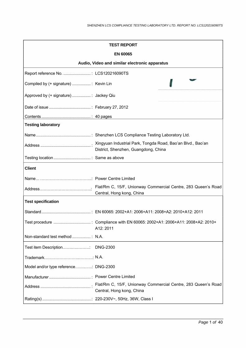
Fig. 3 Back view
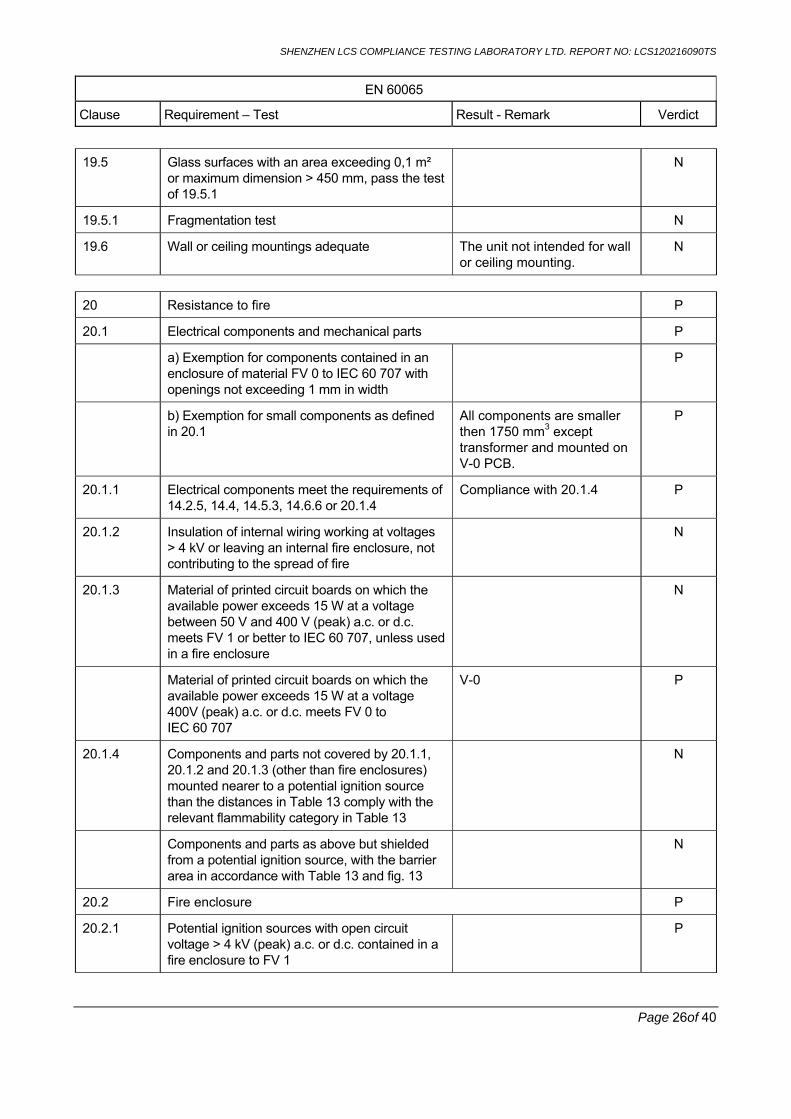
Fig. 4 Overview


![E/CN.16/2013/2 [Arabic version] - unctad.org · e/cn.16/2013/2 3 ge.13-50332 ﺔﻣﺪﻘﻣ ﰲﻭ .ﻞـﻴﺜﻣ ﻪـﻟ ﻖﺒﺴـﻳ ﱂ ﹰﺎﻋﺭﺎ ﺴﺗ ﺔﻴﻣﺎﻨﻟﺍ](https://static.fdocuments.in/doc/165x107/5dd08bf8d6be591ccb61841e/ecn1620132-arabic-version-ecn1620132-3-ge13-50332-iiiii-ii.jpg)