TEST REPORT EN 55014-2 (1997) +A1 (2001) - Aula Solar CE MCE 20-25.pdf · · 2014-05-21Page 1 of...
23
Page 1 of 23 Report No. 99559-5TRFEMC TRF No. TRF EMC SpA TEST REPORT EN 55014-2 (1997) +A1 (2001) Electromagnetic compatibility - Requirements for household appliances, electric tools and similar apparatus Part 2: Immunity Report Reference No. .................... : 99559-5TRFEMC Tested by ........................................ : Daniele Guarnone Approved by .................................... : Paolo Barbieri Date of issue .................................... : 2008-01-16 Testing Laboratory ........................ : Nemko Spa Address ............................................ : Via del Carroccio, 4 I-20046 Biassono MI (Italy) Testing location/ procedure.............. : Full application of Harmonised standards Partial application of Harmonised standards Other standard testing methods Non-standard testing methods SINAL accredited test report Testing location/ address ................. : Nemko Spa - Via del Carroccio, 4 I-20046 Biassono MI (Italy) Applicant’s name ........................... : ELCO S.P.A. Address ............................................ : Via Marconi, 1 20065 Inzago Milano I Test specification: Standard .......................................... : EN 55014-2 (1997) +A1 (2001) Test procedure................................. : Nemko WML1002 and WML0177 Non-standard test method…………..: N/A Test Report Form No. .................... : TRF EMC SpA TRF Originator ................................. : Nemko Spa Master TRF ...................................... : 2005-04 Nemko Spa, I-20046 Biassono MI, Italy. All rights reserved. This publication may be reproduced in whole or in part for non-commercial purposes as long as the Nemko Spa is acknowledged as copyright owner and source of the material. Nemko Spa takes no responsibility for and will not assume liability for damages resulting from the reader's interpretation of the reproduced material due to its placement and context. Test item description..................... : Electronic Fan Trade Mark ...................................... : Manufacturer .................................... : ELCO S.P.A. Model/Type reference ...................... : MCE 20-25 Ratings ............................................. : 230 Vac (1600 rpm) This test report may not be partially reproduced, except with the prior written permission of Nemko Spa
Transcript of TEST REPORT EN 55014-2 (1997) +A1 (2001) - Aula Solar CE MCE 20-25.pdf · · 2014-05-21Page 1 of...

Page 1 of 23 Report No. 99559-5TRFEMC
TRF No. TRF EMC SpA
TEST REPORT EN 55014-2 (1997) +A1 (2001)
Electromagnetic compatibility - Requirements for household appliances, electric tools and similar apparatus Part 2: Immunity
Report Reference No . .................... : 99559-5TRFEMC
Tested by ........................................ : Daniele Guarnone
Approved by .................................... : Paolo Barbieri
Date of issue.................................... : 2008-01-16
Testing Laboratory ........................ : Nemko Spa
Address............................................ : Via del Carroccio, 4 I-20046 Biassono MI (Italy)
Testing location/ procedure.............. : Full application of Harmonised standards Partial application of Harmonised standards Other standard testing methods Non-standard testing methods SINAL accredited test report
Testing location/ address................. : Nemko Spa - Via del Carroccio, 4 I-20046 Biassono MI (Italy)
Applicant’s name ........................... : ELCO S.P.A.
Address............................................ : Via Marconi, 1 20065 Inzago Milano I
Test specification:
Standard .......................................... : EN 55014-2 (1997) +A1 (2001)
Test procedure................................. : Nemko WML1002 and WML0177
Non-standard test method…………..: N/A
Test Report Form No . .................... : TRF EMC SpA
TRF Originator ................................. : Nemko Spa
Master TRF...................................... : 2005-04
Nemko Spa, I-20046 Biassono MI, Italy. All rights r eserved.
This publication may be reproduced in whole or in part for non-commercial purposes as long as the Nemko Spa is acknowledged as copyright owner and source of the material. Nemko Spa takes no responsibility for and will not assume liability for damages resulting from the reader's interpretation of the reproduced material due to its placement and context.
Test item description..................... : Electronic Fan
Trade Mark ...................................... :
Manufacturer.................................... : ELCO S.P.A.
Model/Type reference ...................... : MCE 20-25
Ratings............................................. : 230 Vac (1600 rpm)
This test report may not be partially reproduced, except with the prior written permission of Nemko Spa

Page 2 of 23 Report No. 99559-5TRFEMC
TRF No. TRF EMC SpA
EMC -- T E S T R E P O R T
Test Report No. :
99559-5TRFEMC 2008-01-16 ______________________________________________________________________________________________
Date of issue
Type / Model : MCE 20-25 Equipment : Electronic Fan Applicant : ELCO S.P.A. Address : Via Marconi, 1
20065 Inzago Milano I Manufacturer : ELCO S.P.A. Address : Via Marconi, 1
20065 Inzago Milano I
Test Result according to the standards on page 4:
Positive
The test report merely corresponds to the test sample. It is not permitted to copy extracts of these test result without the written permission of the test laboratory.

Page 3 of 23 Report No. 99559-5TRFEMC
TRF No. TRF EMC SpA
Contents
1 T E S T S T A N D A R D S 4
2 S U M M A R Y 5
3 E Q U I P M E N T U N D E R T E S T 6
3.1 POWER SUPPLY SYSTEM UTILISED 6 3.2 SHORT DESCRIPTION OF THE EQUIPMENT UNDER TEST (EUT) 6 3.3 PERFORMANCE LEVEL 7
4 T E S T E N V I R O N M E N T 9
4.1 ADDRESS OF THE TEST LABORATORY 9 4.2 ENVIRONMENTAL CONDITIONS 9 4.3 DEFINITIONS OF SYMBOLS USED IN THIS TEST REPORT 9 4.4 STATEMENT OF THE MEASUREMENT UNCERTAINTY 10
5 T E S T C O N D I T I O N S A N D R E S U L T S 1 1
5.1 ELECTROSTATIC DISCHARGE 11 5.2 ELECTRICAL FAST TRANSIENTS / BURST 13 5.3 CONDUCTED DISTURBANCES INDUCED BY RADIO -FREQUENCY FIELDS 15 5.4 VOLTAGE DIPS AND SHORT INTERRUPTIONS 17 5.5 SURGE 19
7 U S E D T E S T E Q U I P M E N T 2 1
7 P H O T O S 2 2
Page 4 of 23 Report No. 99559-5TRFEMC
TRF No. TRF EMC SpA
1 T E S T S T A N D A R D S The tests were performed according to following standards: Nemko WML0177: Use of measuring equipment to perform standards tests. Nemko WML1002: Measurement Uncertainty - Policy and Statement EN 55014-2 (1997) +A1 (2001) Electromagnetic compatibility - Requirements for household appliances, electric tools and similar apparatus -- Part 2: Immunity EN 61000-4-2 (1995) + A1 (1998) + A2 (2001) Electromagnetic compatibility (EMC) -- Part 4-2: Testing and measurement techniques - Electrostatic discharge immunity test EN 61000-4-4 (2004) Electromagnetic compatibility (EMC) -- Part 4-4: Testing and measurement techniques - Electrical fast transient/burst immunity test EN 61000-4-5 (2006) Electromagnetic compatibility (EMC) -- Part 4-5: Testing and measurement techniques - Surge immunity test EN 61000-4-6 (1996) + A1( 2001) Electromagnetic compatibility (EMC) -- Part 4-6: Testing and measurement techniques - Immunity to conducted disturbances, induced by radio-frequency fields EN 61000-4-11 (2004) Electromagnetic compatibility (EMC) -- Part 4-11: Testing and measurement techniques - Voltage dips, short interruptions and voltage variations immunity tests

Page 5 of 23 Report No. 99559-5TRFEMC
TRF No. TRF EMC SpA
2 S U M M A R Y GENERAL REMARKS: // FINAL ASSESSMENT: The EMC requirements pertaining to the technical standards and tested operation modes are - fulfilled. The equipment under test - fulfils the EMC requirements cited on page 4. Date of receipt of test sample : 2007-12-06 Testing commenced on : 2007-12-06 Testing concluded on : 2007-12-06

Page 6 of 23 Report No. 99559-5TRFEMC
TRF No. TRF EMC SpA
3 E Q U I P M E N T U N D E R T E S T
3.1 Power supply system utilised
Power supply voltage : 230V/50 Hz / 1φ
3.2 Short description of the Equipment under Test ( EuT) The EUT is a electronic fan Number of tested samples: 1 Serial number: - E.U.T. category: II according to EN 55014 (internal clock 4 MHz) EuT operation mode: The equipment under test was operated during the measurement under the following conditions: o - Standby - According to standards requirements Immunity tests: 1450 rpm EuT configuration: The following peripheral devices and interface cabl es were connected during the measurement : AC mains cable Model : - - unscreened power cables - customer specific cables

Page 7 of 23 Report No. 99559-5TRFEMC
TRF No. TRF EMC SpA
3.3 Performance level The test results shall be classified in terms of the loss of function or degradation of performance of the equipment under test, relative to a performance level defined by its manufacturer or the requestor of the test, or agreed between the manufacturer and the purchaser of the product.
Definition related to the performance level: based on the used product standard based on the declaration of the manufacturer, requestor or purchaser

Page 8 of 23 Report No. 99559-5TRFEMC
TRF No. TRF EMC SpA

Page 9 of 23 Report No. 99559-5TRFEMC
TRF No. TRF EMC SpA
4 T E S T E N V I R O N M E N T
4.1 Address of the test laboratory
Nemko Spa Via del Carroccio, 4 I-20046 Biassono MI
4.2 Environmental conditions
During the measurement the environmental conditions were within the listed ranges: Temperature: 18-28 ° C Humidity: 30-60 % Atmospheric pressure: 86-106 kPa
4.3 Definitions of symbols used in this test report
- The black square indicates that the listed condition, standard or equipment is applicable for this report. o - The empty circle indicates that the listed condition, standard or equipment is not applicable for this report.

Page 10 of 23 Report No. 99559-5TRFEMC
TRF No. TRF EMC SpA
4.4 Statement of the measurement uncertainty
The data and results referenced in this document are true and accurate. The reader is cautioned that there may be errors within the calibration limits of the equipment and facilities. The measurement uncertainty was calculated for all measurements listed in this test report according to CISPR 16 - 4 „Specification for radio disturbance and immunity measuring apparatus and methods – Part 4: Uncertainty in EMC Measurements“ and is documented in the Nemko Spa Technical Procedure Nemko WML1002. Furthermore, component and process variability of devices similar to that tested may result in additional deviation. The manufacturer has the sole responsibility of continued compliance of the device. Hereafter the best measurement capability for Nemko Spa laboratory is reported:
Test
Range
Measurement Uncertainty
Notes
Antenna distance 3m (30÷200) MHz
± 5.2 dB (1)
Antenna distance 3m (200÷1000) MHz
± 4.9 dB (1)
Antenna distance 10m (30÷200) MHz
± 5.0 dB (1)
Radiated Emission
Antenna distance 10m (200÷1000) MHz
± 4.8 dB (1)
Conducted Emission 9 kHz ÷ 30 MHz ± 2.8 dB (1) Clicks 9 kHz ÷ 30 MHz ± 2.8 dB (1)
Radiated Power Emission (30÷300) MHz ± 4.0 dB (1) Harmonic Current Emission 50 Hz ÷ 2 kHz ± 2% (1)
Voltage Fluctuation Emission -- ± 2% (1) Radiated Immunity 20 MHz ÷ 2.5 GHz (0.0 ÷ 6.0) dB (1)
Conducted RF Immunity 9 kHz ÷ 230 MHz ± 2.0 dB (1) ESD Immunity -- ± 6% (1) Burst Immunity -- ± 2% (1) Surge Immunity -- ± 2% (1) Dips Immunity -- ± 2% (1)
Magnetic Field Immunity 50 Hz ± 2.0dB (1)
Damped Magnetic Field Immunity 100 kHz, 1 MHz ± 3 dB ampl. ± 10% freq.
(1)
Oscillatory Wave Immunity 100 kHz, 1 MHz ± 20% (1) Low Frequency Immunity 15 Hz ÷ 150 kHz ± 2.0 dB (1)
NOTES: (1) The reported expanded uncertainty of measurement is stated as the standard uncertainty of measurement
multiplied by the coverage factor k = 2 which has been derived from the assumed normal probability distribution with infinite degrees of freedom and for a coverage probability of 95 %;
Page 11 of 23 Report No. 99559-5TRFEMC
TRF No. TRF EMC SpA
5 T E S T C O N D I T I O N S A N D R E S U L T S
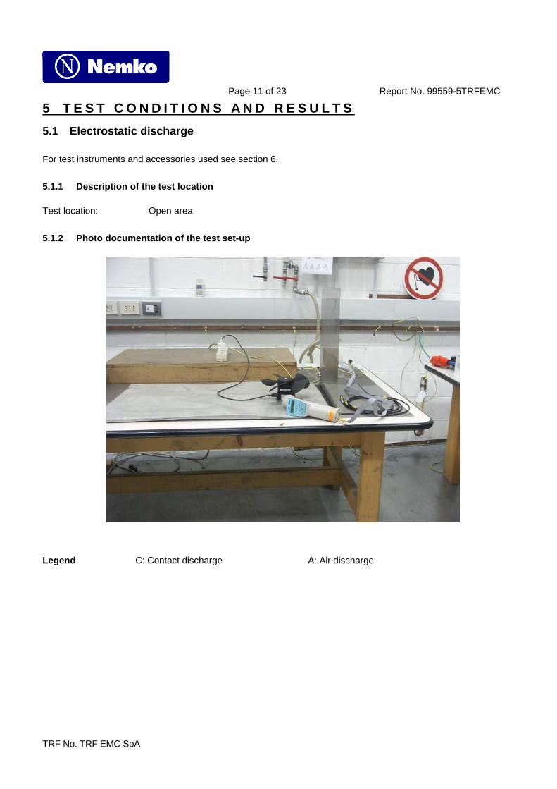
5.1 Electrostatic discharge
For test instruments and accessories used see section 6.
5.1.1 Description of the test location Test location: Open area
5.1.2 Photo documentation of the test set-up
Legend C: Contact discharge A: Air discharge

Page 12 of 23 Report No. 99559-5TRFEMC
TRF No. TRF EMC SpA
5.1.3 Test specification: Contact discharge voltage: 2 kV 4 kV o 6 kV o 8 kV Air discharge voltage: 2 kV 4 kV 8 kV o 15 kV Discharge impedance: 330 Ω / 150 pF Discharge factor: ≥ 1 sec. Number of discharges: ≥ 10 Type of discharge: Direct discharge o Air discharge Contact discharge Indirect discharge Air discharge Polarity: Positive Negative Discharge location: o see photo documentation of the test set-up all external locations accessible by hand horizontal plate (HCP) vertical coupling plate (VCP)
5.1.4 Test result The requirements are Fulfilled Performance Criterion B Remarks: During the test no deviation was detected to the selected operation mode(s).

Page 13 of 23 Report No. 99559-5TRFEMC
TRF No. TRF EMC SpA
5.2 Electrical fast transients / Burst
For test instruments and accessories used see section 6.
5.2.1 Description of the test location Test location: Open area
5.2.2 Photo documentation of the test set-up
5.2.3 Test specification: Coupling network: o 0.5 kV 1 kV o 2 kV o 4 kV Coupling clamp: o 0.5 kV o 1 kV Burst frequency: 5.0 kHz Coupling duration: 120 s Polarity: positive negative

Page 14 of 23 Report No. 99559-5TRFEMC
TRF No. TRF EMC SpA
5.2.4 Coupling points Cable description (Port1): AC mains Screening: o screened unscreened
o passive o active o analogue o digital
Status: Signal transmission: Length: 1 m
5.2.5 Test result The requirements are Fulfilled Performance Criterion B Remarks: During the test no deviation was detected to the selected operation mode(s).

Page 15 of 23 Report No. 99559-5TRFEMC
TRF No. TRF EMC SpA
5.3 Conducted disturbances induced by radio-frequen cy fields
For test instruments and accessories used see section 6.
5.3.1 Description of the test location Test location: Open area
5.3.2 Photo documentation of the test set-up
5.3.3 Test specification: Frequency range: 0.15 MHz to 230 MHz Test voltage: 3 V Modulation: AM: 80 %
sinusoidal 1000Hz Frequency step: 1 % with 3 s dwell time
Page 16 of 23 Report No. 99559-5TRFEMC
TRF No. TRF EMC SpA
5.3.4 Coupling points Cable description (Port1): AC mains Screening: o screened unscreened
o passive o active o analogue o digital
Status: Signal transmission: Length: 1 m
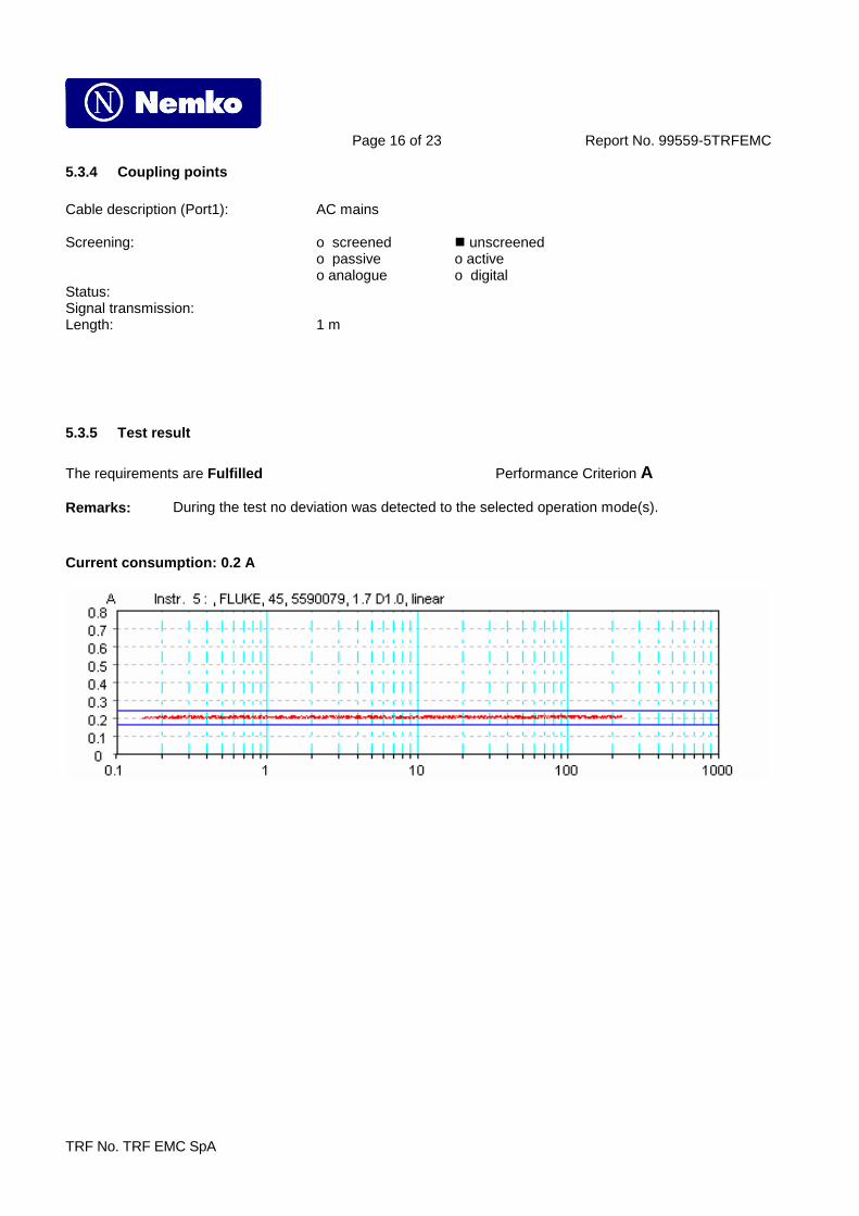
5.3.5 Test result The requirements are Fulfilled Performance Criterion A Remarks: During the test no deviation was detected to the selected operation mode(s).
Current consumption: 0.2 A
Page 17 of 23 Report No. 99559-5TRFEMC
TRF No. TRF EMC SpA
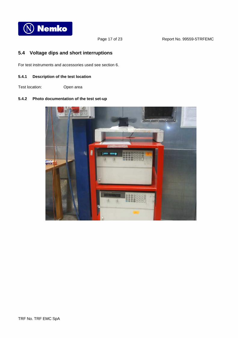
5.4 Voltage dips and short interruptions
For test instruments and accessories used see section 6.
5.4.1 Description of the test location Test location: Open area
5.4.2 Photo documentation of the test set-up

Page 18 of 23 Report No. 99559-5TRFEMC
TRF No. TRF EMC SpA
5.4.3 Test specification: Nominal Mains Voltage (VN): 230 V AC Number of voltage fluctuations: 3 Level of reduction(dip) / duration: > 95 % / 10ms Level of reduction(dip) / duration: 60 % / 200ms Level of reduction(dip) / duration: 30 % / 1000ms
5.4.4 Test result The requirements are Fulfilled Performance Criterion C Remarks: During the test no deviation was detected to the selected operation mode(s).

Page 19 of 23 Report No. 99559-5TRFEMC
TRF No. TRF EMC SpA
5.5 Surge
For test instruments and accessories used see section 6.
5.5.1 Description of the test location Test location Open area
5.5.2 Photo documentation of the test set-up
5.5.3 Test specification: Pulse amplitude-Power line sym.: Source impedance: 2 Ω + 18µF
o 0.5 kV 1 kV o 2 kV o 4 kV
Pulse amplitude-Power line unsym: Source impedance: 12 Ω + 9µF
o 0.5 kV o 1 kV 2 kV o 4 kV
Number of surges: 5 Surges/Phase angle Phase angle: 0 ° 90 ° 180 ° 270 ° Repetition rate: 60 s Polarity: positive negative
Page 20 of 23 Report No. 99559-5TRFEMC
TRF No. TRF EMC SpA
5.5.4 Coupling points Cable description (Port1): AC mains Screening: o screened unscreened
o passive o active o analogue o digital
Status: Signal transmission: Length: 1 m
5.5.5 Test result The requirements are Fulfilled Performance Criterion B Remarks: During the test no deviation was detected to the selected operation mode(s).
Page 21 of 23 Report No. 99559-5TRFEMC
TRF No. TRF EMC SpA
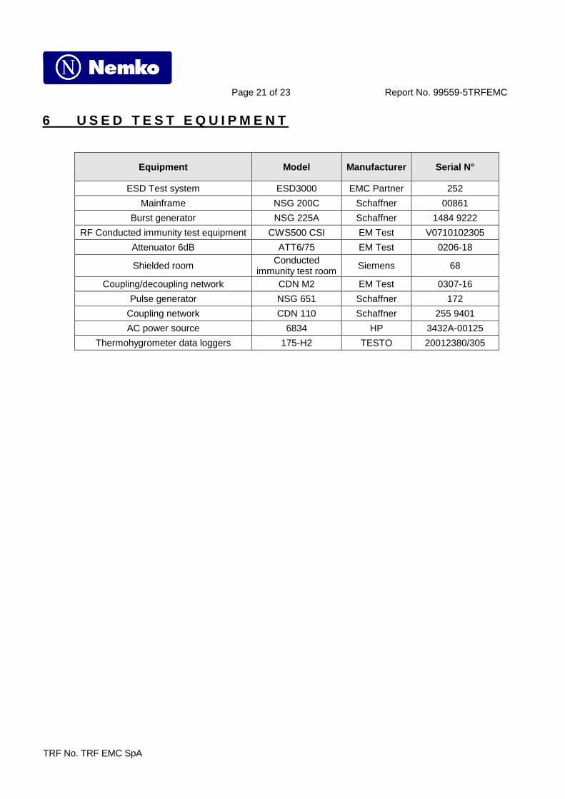
6 U S E D T E S T E Q U I P M E N T
Equipment Model Manufacturer Serial N°
ESD Test system ESD3000 EMC Partner 252
Mainframe NSG 200C Schaffner 00861
Burst generator NSG 225A Schaffner 1484 9222
RF Conducted immunity test equipment CWS500 CSI EM Test V0710102305
Attenuator 6dB ATT6/75 EM Test 0206-18
Shielded room Conducted immunity test room
Siemens 68
Coupling/decoupling network CDN M2 EM Test 0307-16
Pulse generator NSG 651 Schaffner 172
Coupling network CDN 110 Schaffner 255 9401
AC power source 6834 HP 3432A-00125
Thermohygrometer data loggers 175-H2 TESTO 20012380/305

Page 22 of 23 Report No. 99559-5TRFEMC
TRF No. TRF EMC SpA
7 P H O T O S

Page 23 of 23 Report No. 99559-5TRFEMC
TRF No. TRF EMC SpA