
Upper Limb Orthopaedic Medicine Scope Neck Shoulder Elbow Wrist Hand.
Test method – Upper neck force and
moment
LAURA VILA GIRAUT
Department of Applied Mechanics
Division of Vehicle Safety
CHALMERS UNIVERSITY OF TECHNOLOGY
Göteborg, Sweden 2010
Master’s Thesis 2010:15

MASTER’S THESIS 2010:15
Test method – Upper neck force and moment
LAURA VILA GIRAUT
Department of Applied Mechanics
Division of Vehicle Safety
CHALMERS UNIVERSITY OF TECHNOLOGY
Göteborg, Sweden 2010

Test method – Upper neck force and moment
LAURA VILA GIRAUT
© LAURA VILA GIRAUT, 2010
Master’s Thesis 2010:15
ISSN 1652-8557
Department of Applied Mechanics
Division of Vehicle Safety
Chalmers University of Technology
SE-412 96 Göteborg
Sweden
Telephone: + 46 (0)31-772 1000
Cover:
From Anna Carlsson
Printed at Chalmers Reproservice / Department of Applied Mechanics
Göteborg, Sweden 2010
I
Test method – Upper neck force and moment
LAURA VILA GIRAUT
Department of Applied Mechanics
Division of Vehicle Safety
Chalmers University of Technology
ABSTRACT
Crash tests are used to develop and improve vehicle safety and evaluate the injuries
caused after a crash. In the neck, injury criteria such as NIC and 𝑁𝑘𝑚 estimate
consequences of the crash. In a crash test dummy the upper neck load cell measures
the force and the moments between the neck and the head. But in volunteer tests,
always non-injurious and at low velocity, is not possible to attach sensors into the
neck of the volunteers. Hence the forces and moments in volunteers need to be
calculated with data from accelerometers or possible other sensors.
The aim of this thesis is to propose a method that can be used to calculate the upper
neck forces and moments on human subjects.
A review of different methods to calculate the upper neck force and moments has
been performed. Advantages and disadvantages have been discussed. Also the
physical properties of the human head (mass, moment of inertia, position of the center
of gravity and the occipital condyle) are investigated as they are important in the
calculation of the upper neck loads.
In order to calculate the upper neck force and moment in a crash test carried out with
a human subject, the head of the human is considered to be a solid rigid. Therefore,
forces and moments in the upper neck are found by applying the dynamics of a solid
rigid.
As a result of the research, a method is proposed: attach a new sensor in the market
(IMT40) in both sides of the projection of the center of gravity in the human head,
measure linear and angular acceleration and the angle of the head and finally calculate
the neck loads.
Keywords: volunteer, human subject, forces and moments in the upper neck, female,
rear impact.

II

III
Contents
ABSTRACT I
CONTENTS III
ACKNOWLEDGMENTS V
NOTATIONS VII
1 INTRODUCTION 1
1.1 Whiplash injuries 1 1.1.1 What is a whiplash 1 1.1.2 Symptoms of the whiplash 2
1.1.3 Some statistics of the whiplash 3
1.2 Structure of the neck 3
1.3 Neck injury criteria 4
1.4 Rear impact dummies 5
1.5 Rear impact volunteer tests 6 1.5.1 Difficulties on volunteer tests 6
1.5.2 Advantages of volunteer tests 6
1.6 Aim of the study 6
2 REVIEW OF ASSESSMENT METHODS 8
2.1 The head is considered to be in plane motion 8
2.2 The head is considered to be in 3D motion 8
2.3 Chronology of the studies 10
2.4 Mertz and Patrick study 11 2.4.1 Characteristics of the method used 11 2.4.2 Coordinate system 11 2.4.3 Free body diagram of the head 12
2.4.4 Equations applied 14 2.4.5 Calculation of the accelerations of the center of gravity of the head 14 2.4.6 Human subject head instrumentation 15
2.5 A. van den Kroonenberg et al. study 16 2.5.1 Characteristics of the method used 16 2.5.2 Head anatomical coordinate system 17 2.5.3 Free body diagram of the head 17
2.5.4 Neck loads 18 2.5.5 Calculation of the accelerations of the center of gravity of the head 19 2.5.6 Instrumentation 19 2.5.7 Human subject head instrumentation 19
2.6 Japanese studies (Ono et al. 1996, 1997, 2000, 2006) 20
2.6.1 Head strap + mouthpiece (Ono et al. 1996, 1997, 2000) 20 2.6.2 Mouthpiece (Ono et al. 2006) 21
2.7 Advantages and disadvantages of the different methods 22

IV
3 REVIEW OF HUMAN HEAD PROPERTIES 24
3.1 Center of gravity of the head 24 3.1.1 Summary 27
3.2 Mass of the head 27
3.2.1 Summary 29
3.3 Moment of inertia of the head 30 3.3.1 Anthropometric measurements 32 3.3.2 Comparison between males and females 32
3.4 Position of the occipital condyle 33
3.4.1 Summary 34
3.5 Important aspects of the head properties 34
4 IMT40 35
5 SENSITIVITY REGARDING THE POSITION OF THE OC 37
5.1 Differences varying the OC position in x and z directions 40
6 CONCLUSIONS 42
7 RECOMMENDATIONS 43
8 REFERENCES 45
9 APPENDIX 48
V
Acknowledgments
This thesis work was carried out at VTI (Swedish National Road and Transport
Research Institute) and at Department of Applied Mechanics, division of Vehicle
Safety from Chalmers University of Technology. It’s the final project of my
university degree in Spain, but within the Erasmus Program, I had the opportunity to
do it in Göteborg, Sweden.
I want to thank all the people who have helped me in the thesis, specially:
My examiner, Mats Svensson from Chalmers, because he gave me the opportunity to
work in this project.
Anna Carlsson, my supervisor from VTI, for her guidance all the time, her help when
I was lost on the work and her good advises. Also for the review of the report and her
corrections.
Johan Davidsson, Deparment of Applied Mechanics, for the meetings I had with him
and for providing me his data from his volunteer experiments in rear impacts.
All the staff at VTI.
Kenneth Malmström and Peter Björkholm, at IMEGO.
And finally, to my family and friends for constant support.

VI

VII
Notations
Abbreviations
AIS Abbreviated Injury Scale
AM Auditory Meatus
BMD Biomedical Computer Program
C1-C7 Cervical vertebrae
CG Center of Gravity of the head
IRCOBI International Research Council on Biomechanics of Injury
MRI Magnetic Resonance Imaging
NIC Neck Injury Criteria
𝑁𝑘𝑚 Neck Protection Criteria
OC Occipital Condyle
R Multiple correlation coefficient
SAHR Saab Active Head Restraint
SD Standard Deviation
SE EST Standard error of estimate
SG Specific Gravity
T1 First Thoracic Vertebra
WHIPS Whiplash Protection System
3D Three Dimensional
Terms
𝐹𝑧 , ROCz, 𝐹𝑂𝐶𝑧 Axial force
𝐹𝑥 , ROCx, 𝐹𝑂𝐶𝑥 Shear force
𝑚 Mass of the head
𝑎𝐶𝐺𝑖 Acceleration of the center of gravity in the i-axis
𝐼𝑖 Mass moment of inertia of the head in the i-axis
𝛼𝑖 Angular acceleration in the i-axis
𝑀𝐶𝐺 Moment of the force in the OC
𝐿𝑜 Moment of momentum
𝜔𝑖 Angular velocity in the i-axis
𝜕 Derivative operator
Cross product operator
θ, 𝜑 angle between the x-axis of the coordinate system and the
horizontal line or the angle between the weight and the z-axis
RHRi, 𝐹𝐻𝑅𝑖 Headrest load in i direction
dHRi Distance between RHRi and i-axis
dOCi, 𝑑𝑂𝐶/𝐶𝐺𝑖 Distance between ROCi and i-axis
𝑂𝑃𝑖 Distance between two arbitrary points (the O-point and the P-
point) in i-direction
𝜌 Density of the human body
𝜌𝐻2𝑂 Density of the water
𝑉 Volume of the head
𝐹𝑖𝑛𝑡 , 𝑀𝑖𝑛𝑡 Critical intercept values
VIII
Constants
𝑔 (9.81m/s2) Acceleration due to the gravity
Concepts
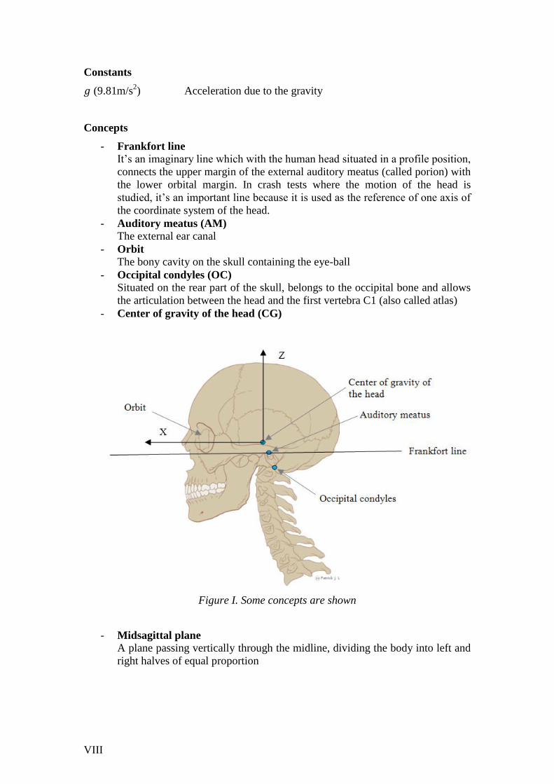
- Frankfort line
It’s an imaginary line which with the human head situated in a profile position,
connects the upper margin of the external auditory meatus (called porion) with
the lower orbital margin. In crash tests where the motion of the head is
studied, it’s an important line because it is used as the reference of one axis of
the coordinate system of the head.
- Auditory meatus (AM)
The external ear canal
- Orbit
The bony cavity on the skull containing the eye-ball
- Occipital condyles (OC)
Situated on the rear part of the skull, belongs to the occipital bone and allows
the articulation between the head and the first vertebra C1 (also called atlas)
- Center of gravity of the head (CG)
Figure I. Some concepts are shown
- Midsagittal plane
A plane passing vertically through the midline, dividing the body into left and
right halves of equal proportion

IX
Figure II. Midsagittal plane
- Kinematics
Describe the motion of objects without consideration of the causes which
provoke the motion
- Kinetics
It’s the general term given to the forces that cause the movement
- Shear force (Fx) The force along the x-axis
- Axial force (Fz) The force along the z-axis
- Coordinate reference system of the head (anatomically based coordinate
reference system for the head)
It has its origin at the midpoint of a line between the external audiotry meatus
from both sides in the midsagittal plane. The x-axis direction is posterior
toward anterior and lies on the Frankfort plane. The z-axis lies in the
midsagittal plane, with 90º from the x-axis and its direction is inferior toward
superior. The y-axis is perpendicular to the midsagittal plane and its direction
follows the right-hand rule, it goes from right to left.
Figure III. Coordinate reference system of the head

X

CHALMERS, Applied Mechanics, Master’s Thesis 2010:15 1
1 Introduction
Nowadays that the population have grown and thus the number of cars too, car
collisions have increased. In the cities during rush hours, when traffic jams are
habitual, rear-end impacts happen usually. In this sort of accidents at a low velocity,
the neck is damaged in most of them. These injuries are known with the name
“whiplash injury”, although at present other names are used, for instance whiplash
associated disorder (WAD), cervical spine injury… (Carlsson, 2010).
1.1 Whiplash injuries
Whiplash injuries occur in all impact directions (frontal, frontal-oblique, lateral,
rear…) in vehicle collisions but also can occur diving. However, they are more
frequent, and the risk is higher, in rear end impacts (Cappon et al. 2003).
The great majority of neck injuries caused by rear-end impacts are considered non-
severe injuries, usually graded as AIS1 (minor injuries).
1.1.1 What is a whiplash
Whiplash is a neck injury caused by a fast and violent forced movement of the neck.
However, they are normally non-life threatening.
The phases of the motion of the head in a typical rear-end impact are:
- Neutral position
A relax position of the head and neck
- S-shape
The lower part of the neck is in an
extension position and the upper part
of the neck is in a flexion position.
- Extension
The head has a rearward rotation
- Flexion (rebound)
The head has a forward rotation
Figure 1. Neck in the
neutral position
Figure 3. Neck
in extension
Figure 4. Neck
in flexion
Figure 2. S-shape

CHALMERS, Applied Mechanics, Master’s Thesis 2010:15 2
Whiplash mechanism can be defined in three steps (Carlsson 2010):
1) When the vehicle is hit from the rear by another vehicle, the torso tends to
move forward, pushed by the seatback; whereas the head remains at the same
position. The neck achieves a position known as S-shape (or retraction).
2) The following phase is the extension, and it occurs because the torso is still
pushed forward and the head will be bent backwards.
3) Finally, the seat belt stops the forward movement of the torso, but the head
moves forward. The head achieves flexion.
Although it has been carried out many studies trying to find out the exactly
mechanisms which causes the neck-injury, they are not fully understood (Koshiro
Ono et al., Davidsson 2000, Chen HB et al. 2009).
According to the same authors, Chen HB et al. 2009, one reason might be that these
injuries are not always accompanied by obvious tissue damage detectable by X-ray or
magnetic resonance imaging (MRI).
More knowledge is needed in order to improve the existing anti-whiplash head
restraint or designing new head restraints or other prevention strategies.
1.1.2 Symptoms of the whiplash
Even if the mechanisms of the whiplash are not well understood, the symptoms are
well documented and have been described by several authors (Panjabi et al. 1998,
Davidsson 2000, Ono et al. 1996).
The most common symptoms of the whiplash injury are detailed below. However,
each subject can experience the symptoms in different ways.
- Pain in the neck
- Stiffness if the neck
- Headache
- Dizziness
- Pain in the shoulder
- Pain in the arms
- Pain in the back
- Fatigue
- Difficulty sleeping
- Ringing in the ears
- Nervousness or irritability
- Numbness
- Blurred vision
- …
The duration of the symptoms may vary. The symptoms begin to develop a few hours
after the crash take place, and then get worse over the next 24 to 48 hours; while it is
not habitual the symptoms appear just after the crash (Bierma 2009). Normally they
are not long-lasting and in a few days or months after the crash, the symptoms
disappear. But according to Krafft et al. 2005, a correlation was found between
duration of symptoms and crash severity.
CHALMERS, Applied Mechanics, Master’s Thesis 2010:15 3
1.1.3 Some statistics of the whiplash
The most commonly injury reported in vehicle collisions is whiplash. This statement
can be supported by the fact that in Europe, more than one million people suffer
injuries from rear end collisions (ETSC 2007).
Approximately 80% of all injuries occurring in rear-end collisions are whiplash
injuries (ETSC 2007).
During the last twenty years the number of whiplash injuries has increased. The
previous statistic is not well understood (ETSC 2007) because some systems anti-
whiplash are already in the market since several years ago, as the anti-whiplash head-
restraint from Volvo (WHIPS: Whiplash Protection System), or SAHR (Saab Active
Head Restraint), another anti-whiplash head-restraint… and one study in particular
(Kraft et al. 2004) showed that the new anti-whiplash seats have decreased the
whiplash injury risk (in more than 40%).
Comparing the risk between both genders, it can be said that females had a higher risk
of sustaining neck injury (Ono et al. 2006, Krafft et al. 2005). Also, comparing
passengers and drivers, drivers have a higher risk. The reason is not well known, but a
possible explanation might be that passengers have a more relaxed position than
drivers, and probably they rest their head in the head restraint. And within front
passengers and rear passengers, front passengers have a higher risk than rear
passengers (because of the difference on the rigidity between the front and rear seats)
(ETSC 2007). Focusing on females, they have more than 5 times higher risk than
males in the rear seat; and in the driver position the risk is around 3 times higher in
female (Krafft et al. 2005).
That conclusion from Ono et al. 2006 and Krafft et al. 2005 among other authors is
also supported by a Volkswagen whiplash injury database, which showed that females
have a double whiplash injury risk compare with males. From the same study, it was
found that females between the ages of 18 to 27 years have a higher risk. Another
conclusion was that the risk to suffer a whiplash injury is higher as taller as the person
are (Cappon et al. 2003).
Another reason to investigate the whiplash mechanism is that that kind of injury cost
to the society a high amount of money every year. In 2007, the European society cost
was estimated in more than 10 billion Euros (ETSC 2007).
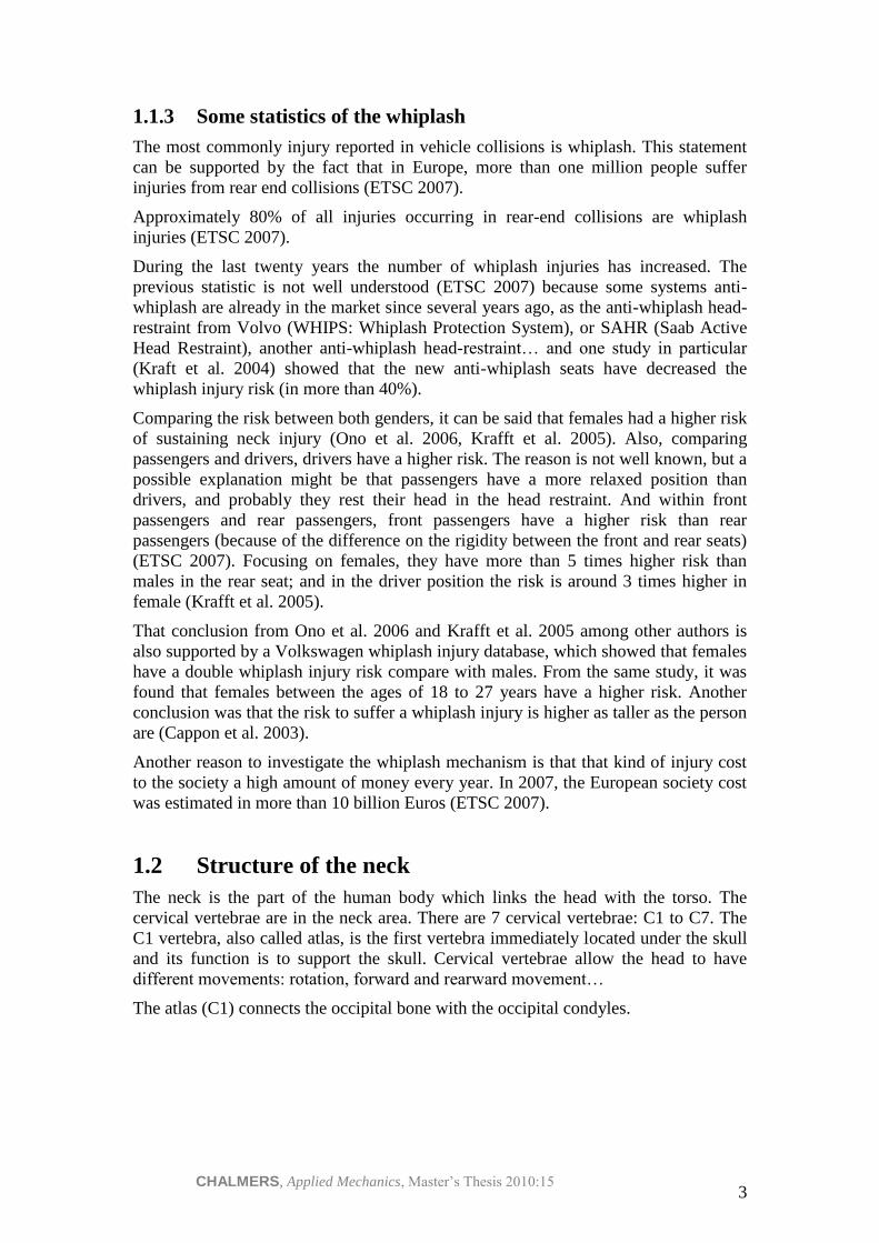
1.2 Structure of the neck
The neck is the part of the human body which links the head with the torso. The
cervical vertebrae are in the neck area. There are 7 cervical vertebrae: C1 to C7. The
C1 vertebra, also called atlas, is the first vertebra immediately located under the skull
and its function is to support the skull. Cervical vertebrae allow the head to have
different movements: rotation, forward and rearward movement…
The atlas (C1) connects the occipital bone with the occipital condyles.
CHALMERS, Applied Mechanics, Master’s Thesis 2010:15 4
Figure 5. Human skull and cervical vertebrae. Picture extracted from
www.wikimedia.org
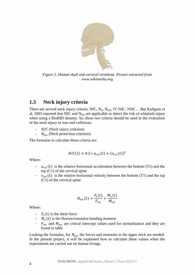
1.3 Neck injury criteria
There are several neck injury criteria: NIC, Nij, Nkm, IV-NIC, NDC… But Kullgren et
al. 2003 reported that NIC and Nkm are applicable to detect the risk of whiplash injury
when using a BioRID dummy. So, these two criteria should be used in the evaluation
of the neck injury in rear-end collisions:
- 𝑁𝐼𝐶 (Neck injury criterion)
- 𝑁𝑘𝑚 (Neck protection criterion)
The formulae to calculate these criteria are:
𝑁𝐼𝐶 𝑡 = 0.2 ∗ 𝑎𝑟𝑒𝑙 𝑡 + 𝑣𝑟𝑒𝑙 (𝑡) 2
Where:
- 𝑎𝑟𝑒𝑙 𝑡 is the relative horizontal acceleration between the bottom (T1) and the
top (C1) of the cervical spine
- 𝑣𝑟𝑒𝑙 (𝑡) is the relative horizontal velocity between the bottom (T1) and the top
(C1) of the cervical spine
𝑁𝑘𝑚 𝑡 =𝐹𝑥(𝑡)
𝐹𝑖𝑛𝑡+
𝑀𝑦 (𝑡)
𝑀𝑖𝑛𝑡
Where:
- 𝐹𝑥(𝑡) is the shear force
- 𝑀𝑦 (𝑡) is the flexion/extension bending moment
- 𝐹𝑖𝑛𝑡 and 𝑀𝑖𝑛𝑡 are critical intercept values used for normalisation and they are
found in table
Looking the formulae, for 𝑁𝑘𝑚 the forces and moments in the upper neck are needed.
In the present project, it will be explained how to calculate these values when the
experiments are carried out on human livings.
CHALMERS, Applied Mechanics, Master’s Thesis 2010:15 5
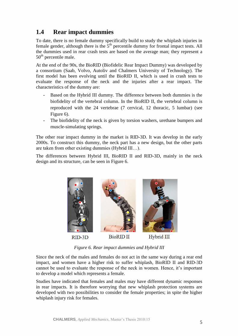
1.4 Rear impact dummies
To date, there is no female dummy specifically build to study the whiplash injuries in
female gender, although there is the 5th
percentile dummy for frontal impact tests. All
the dummies used in rear crash tests are based on the average man; they represent a
50th
percentile male.
At the end of the 90s, the BioRID (Biofidelic Rear Impact Dummy) was developed by
a consortium (Saab, Volvo, Autoliv and Chalmers University of Technology). The
first model has been evolving until the BioRID II, which is used in crash tests to
evaluate the response of the neck and the injuries after a rear impact. The
characteristics of the dummy are:
- Based on the Hybrid III dummy. The difference between both dummies is the
biofidelity of the vertebral column. In the BioRID II, the vertebral column is
reproduced with the 24 vertebrae (7 cervical, 12 thoracic, 5 lumbar) (see
Figure 6).
- The biofidelity of the neck is given by torsion washers, urethane bumpers and
muscle-simulating springs.
The other rear impact dummy in the market is RID-3D. It was develop in the early
2000s. To construct this dummy, the neck part has a new design, but the other parts
are taken from other existing dummies (Hybrid III…).
The differences between Hybrid III, BioRID II and RID-3D, mainly in the neck
design and its structure, can be seen in Figure 6.
Figure 6. Rear impact dummies and Hybrid III
Since the neck of the males and females do not act in the same way during a rear end
impact, and women have a higher risk to suffer whiplash, BioRID II and RID-3D
cannot be used to evaluate the response of the neck in women. Hence, it’s important
to develop a model which represents a female.
Studies have indicated that females and males may have different dynamic responses
in rear impacts. It is therefore worrying that new whiplash protection systems are
developed with two possibilities to consider the female properties; in spite the higher
whiplash injury risk for females.

CHALMERS, Applied Mechanics, Master’s Thesis 2010:15 6
1.5 Rear impact volunteer tests
Until now, several studies have been carried out with male volunteers in rear end
impact to characterize a threshold for the forces and moments produced on the union
between the neck and the head and also to study the whiplash injuries (Mertz et al.
1967, Mertz et al. 1971, A. van den Kroonenberg et al. 1998, Ono et al. 1993, 1997,
2006, Davidsson 2000). But there are fewer studies with females, only two: A. van
den Kroonenberg et al. 1998, Ono et al. 2006, in which experiments participated 3 and
2 volunteer females, respectively. All experiments (except one, Mertz et al. 1967,
which was carried out at an unusual high velocity (71 km/h) for volunteer
experiments) were carried out always at low speed velocity and without severe
damage for the volunteers.
Although the lack of information related with females, it is believed that head-neck
union have different performance depend on the genders, this means that females and
males do not support the same forces. Females are subjected to higher head and T1
accelerations in a crash with the same characteristics (Ono et al.2006, Carlsson 2010).
There are other variables as the age, the velocity of the impact, the condition of the
neck (if the muscle of the neck is tensed or relaxed), the stiffness of the vehicle, the
head restraint design, the distance between the head and the head restraint and so on.
Several studies have been made relating to the kinematics of the head-neck union, but
less concerning about the kinetics, i.e. the dynamics and forces that cause the
movement.
1.5.1 Difficulties on volunteer tests
When one works with human volunteers, difficulties arise with the instrumentation,
because it is not always possible to attach the instrumentation, as accelerometers or
load cells, in the interested point (for example the center of gravity of the head or the
upper neck). Luckily, the new technologies such as high-speed video camera and the
newest sensors make these measurements easier.
Another limitation is the fact that volunteers cannot be exposed to any degree of
physical damage; the crash has to be non-injurious for them. For that reason, there is a
need to develop mechanical and mathematical models.
The last limitation of volunteer tests is that the age of the human subjects normally
ranges from 18 to 50. Mostly young healthy people are used as volunteers, without
any previous damage on the neck.
1.5.2 Advantages of volunteer tests
The most distinguished advantage is the use of the correct anatomy. The muscle
activity only can be measured on volunteers.
1.6 Aim of the study
The main objectives of the present study are 1) to review existing test methods which
calculate the forces and moments on the upper neck on human subjects, and 2) to
develop mathematical equations. So, the present project will serve as an input to a rear

CHALMERS, Applied Mechanics, Master’s Thesis 2010:15 7
impact test series with female and male volunteers in order to calculate the forces and
the moments in the neck.
Once the experiment has been carried out, the information gathered and analyzed can
be used in the development process of a new female mechanical human surrogate
model (a dummy) and/or mathematical models, since currently there are no such
models.
With this information, the response of the head-neck movement during rear impacts,
which produce the whiplash damage, will be characterized.

CHALMERS, Applied Mechanics, Master’s Thesis 2010:15 8
2 Review of assessment methods
The project has been done after a research process where all the studies with human
volunteers in rear impacts have been analyzed in depth, with the purpose to develop
the equations needed to calculate the forces and moments in the upper neck.
To date, there are only two methods used to calculate the moments and the forces in
the volunteers’ neck during the rear impact.
The head is considered to be a rigid body, but the head can be considered to have
planar movement (in the XZ-plane) or to have 3D motions. Hence, the equations of
the dynamics of a solid rigid are applied.
2.1 The head is considered to be in plane motion
- Fundamental equation of the dynamics of the movement (Newton’s second
Law): when a force is applied in a body, then the body is accelerated.
The relationship between a linear force F and the linear acceleration is
described by the following law:
𝐹 = 𝑚 · 𝑎𝐶𝐺 (1)
Where: m is the mass of the head
𝑎𝐶𝐺 is the measured acceleration
Writing equation (1) for each axis of the plane motion:
𝐹𝑥 = 𝑚 · 𝑎𝐶𝐺𝑥
𝐹𝑧 = 𝑚 · 𝑎𝐶𝐺𝑧
- Fundamental equation of the dynamics of the rotation
𝑀𝑦 = 𝐼𝑦 · 𝛼 (2)
Where: 𝑀𝐶𝐺 is the moment of force
𝛼 is the angular acceleration caused by 𝑀𝐶𝐺
𝐼𝑦 is the mass moment of inertia of the head in the y-axis
2.2 The head is considered to be in 3D motion
- Newton’s second law: is the same as the 2D motion but applied in the three
axes (see equation 1).
𝐹𝑥 = 𝑚 · 𝑎𝐶𝐺𝑥 𝐹𝑦 = 𝑚 · 𝑎𝐶𝐺𝑦
𝐹𝑧 = 𝑚 · 𝑎𝐶𝐺𝑧
CHALMERS, Applied Mechanics, Master’s Thesis 2010:15 9
- Euler’s law: concerning about the rotation of the body because of the moment
of an applied force.
A rigid body which has rotation is controlled by the following equation:
𝑀𝑜 =𝑑
𝑑𝑡𝐿𝑜 (3)
Where:
o 𝑀𝑜 is the moment of the external forces about the chosen origin O
o 𝐿𝑜 is the moment of momentum (also called angular momentum)
and for a rigid body which rotates around a principal axis, it is
equal to:
𝐿𝑜 = 𝐼𝑜 · 𝜔
o 𝐼𝑜 is the moment of inertia matrix with respect to the origin point
O and it’s a symmetrically matrix
o 𝜔 is the angular velocity of the body
Furthermore, if a moving coordinate system is chosen, 𝐼𝑜 keeps constant, so
the calculations are easier. Then, equation (3) is written as:
𝑀𝑜 =
𝜕𝐿𝑜
𝜕𝑡+ 𝜔𝑅 x𝐿𝑜
(4)
Where:
o 𝜔𝑅 is the angular velocity of the moving axes
If the axes are fixed to the body, 𝜔𝑅 = 𝜔 .
Developing equation (4):
𝑀𝑜 =
𝜕(𝐼𝑜 ·𝜔 )
𝜕𝑡+ 𝜔 x 𝐼𝑜 · 𝜔 = 𝐼𝑜 · 𝛼 + 𝜔 x 𝐼𝑜 · 𝜔 (5)
Where 𝜕(𝜔 )
𝜕𝑡 was replaced by 𝛼 (the angular acceleration of the body).
If the tensor of inertia 𝐼𝑜 is calculated with respect to the principal anatomical
axes of the head with their origin at the center of gravity of the head, then it
becomes nonzero diagonal:
𝐼𝑜 =
𝐼𝑥 0 00 𝐼𝑦 0
0 0 𝐼𝑧
Equation (5) is now written in vector form:
𝑀𝑥
𝑀𝑦
𝑀𝑧
=
𝐼𝑥 0 00 𝐼𝑦 0
0 0 𝐼𝑧
·
𝛼𝑥
𝛼𝑦
𝛼𝑧
+
𝜔𝑥
𝜔𝑦
𝜔𝑧
x
𝐼𝑥 0 00 𝐼𝑦 0
0 0 𝐼𝑧
·
𝜔𝑥
𝜔𝑦
𝜔𝑧
(6)
Developing equation (6) the final result is:
𝑀𝑥 = 𝐼𝑥 · 𝛼𝑥 + 𝐼𝑧 − 𝐼𝑦 · 𝜔𝑦 · 𝜔𝑧
𝑀𝑦 = 𝐼𝑦 · 𝛼𝑦 + 𝐼𝑥 − 𝐼𝑧 · 𝜔𝑥 · 𝜔𝑧 (7)
𝑀𝑧 = 𝐼𝑧 · 𝛼𝑧 + 𝐼𝑦 − 𝐼𝑥 · 𝜔𝑥 · 𝜔𝑦
CHALMERS, Applied Mechanics, Master’s Thesis 2010:15 10
The three previous equations are known as the Euler equations and they are
the equations of motion for the 3D kinetic analyses.
Observation: For the case where the head is assumed to have plane motion (XZ-
plane) (see section 2.1), its equation for the moment is a particular case of the Euler
equations, because 𝛼𝑥 , 𝛼𝑧 , 𝜔𝑧 , 𝜔𝑥 = 0 . Thus the Euler equations are written as (see
equation 2):
𝑀𝑦 = 𝐼𝑦 · 𝛼𝑦
Forces in the upper neck and also upper neck moment are assumed to act at the OC
joint.
Although there is only one way to calculate forces and moments on the neck, i.e.
considering the head as a solid rigid, the acceleration in the head of the human
subjects can be measured using different methods to attach the accelerometers in the
volunteer’s head.
2.3 Chronology of the studies
The following chronology is only focused in rear impacts with volunteers where not
only the kinematics of the head-neck were analyzed, but also the upper-neck forces
and moments.
In 1967 H.J. Mertz Jr. and L.M. Patrick from Wayne State University presented a
paper (Investigations of the kinematics and kinetics of whiplash) where forces and
moments in the neck were calculated. In that study, the authors compared the response
of anthropomorphic dummies, human cadavers and a volunteer in a rear impact. It
was one of the first tests using human subjects with the objective of analyze the forces
and moments in the neck.
Four years later, in 1971, the same authors presented another study (Strength and
response of the human neck) with one volunteer and one of the objective of the
mentioned study was to present dynamic response and strength data for the human
neck in flexion and extension.
After 1971, there was a long period (until 1993) where any study was presented
concerning about the forces and moments in the upper neck of a human subject.
In 1993 Koshiro Ono and Munekazu Kanno (Japan) presented at the IRCOBI
Conference another study (Influences of the physical parameters on the risk to neck
injuries in low impact speed rear-end collisions) where the kinematics of the head and
neck were studied and also the kinetics of the human subject.
Four years after, in 1997, Koshiro Ono, the same author of the previous study, but
now working with Koji Kaneoka and Adam Wittek and Janusz Kajzer, presented a
study with the objective of clarify the neck injury mechanism according to the
characteristic motion of cervical vertebrae during impact (Cervical injury mechanism
based on the analysis of human cervical vertebral motion and head-neck-torso
kinematics during low speed rear impacts).
CHALMERS, Applied Mechanics, Master’s Thesis 2010:15 11
In 1998, A.van den Kroonenberg et al. (Germany) published another study with
human subjects (Human head-neck response during low-speed rear end impacts)
where the neck forces and moment were calculated.
In 2000, Koshiro Ono et al. published another study (Analysis of seat properties on
human cervical vertebral motion in low-speed rear-end impacts) related with the
whiplash on the rear impacts using volunteers. The main objective of the study was
clarify the motion of the neck with respect to the difference in seat characteristics and
from the results, be able to design a new seat system which reduces the whiplash
injury.
Davidsson et al. 1998-2000 carried out a few studies (Human volunteer kinematics in
rear-end sled collisions, Human volunteer kinematics in low-speed rear-end sled
impacts) with the main purpose for the validation of a crash test dummies and
mathematical models and also the information gathered have been useful in the
development of the BioRID. They used the same method as Koshiro Ono et al. used in
their experiments: a device which consists with a strap around the head and a
mouthpiece. It will be described later on more detail (see Section 2.6.1).
Koshiro Ono et al., in 2006, did another study (Prediction of neck injury risk based on
the analysis of localized cervical vertebral motion of human volunteers during low-
speed rear impacts) with human subjects and the neck forces and the moment were
also analysed.
As it is said previously, all methods consider the head to be a rigid body. The
difference between the studies is the instrumentation of the volunteers where the
accelerometers are attached.
Below, all the studies are analysed and explained deeply, so the differences can be
observed.
2.4 Mertz and Patrick study
2.4.1 Characteristics of the method used
- To evaluate the severity of the whiplash simulation and the effectiveness of
the safety devices, the neck reactions were determined (see Section 2.4.4).
- The headrest loads were measured directly with a load cell.
- The neck reactions were obtained by applying the equations of dynamic
equilibrium (1) and (2) to the head.
- The neck reactions are calculated on the occipital condyle (OC), at the base of
the skull (see Section 2.4.4).
- In this analysis the head is considered to be a rigid body undergoing plane
motion (see Section 2.1).
Since it is considered the head moves in the plane X-Z (the head is considered to have
plane motion), there is only acting shear force (Fx) and axial force (Fz).
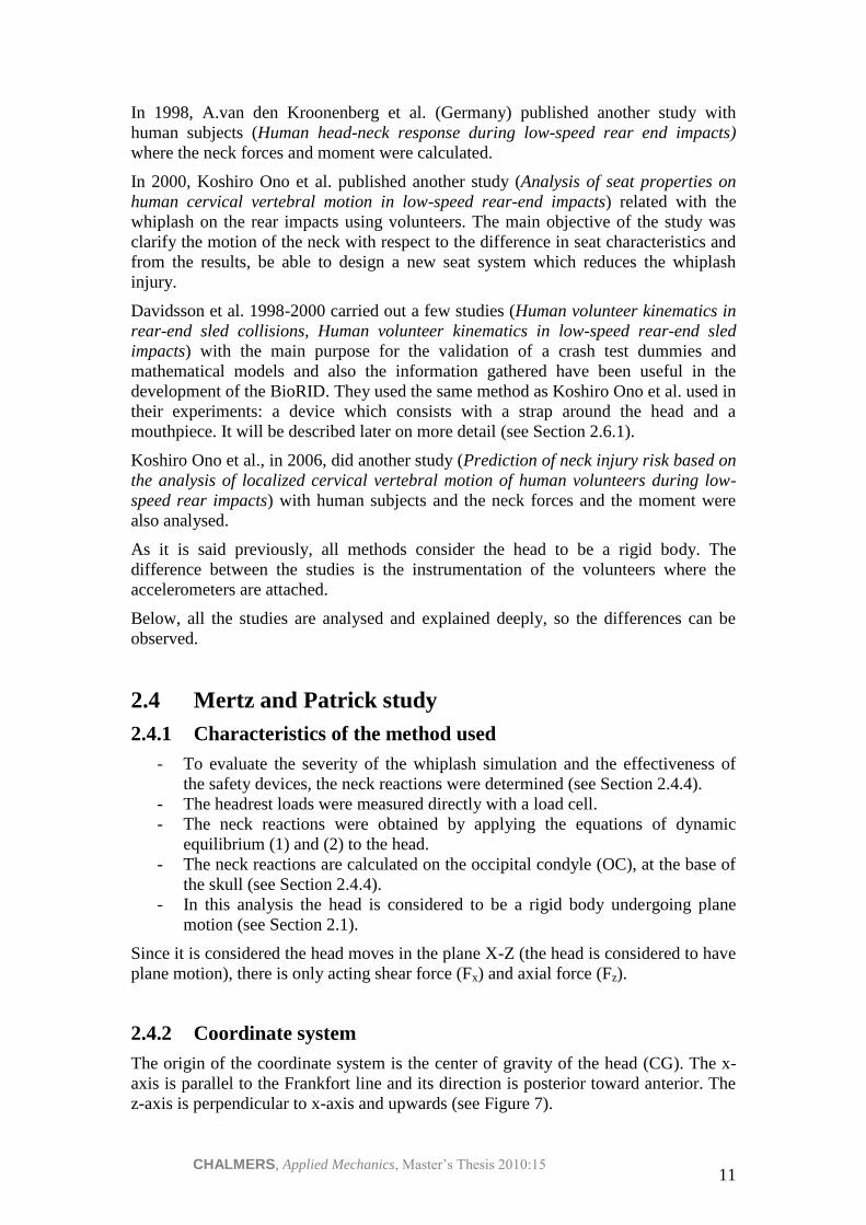
2.4.2 Coordinate system
The origin of the coordinate system is the center of gravity of the head (CG). The x-
axis is parallel to the Frankfort line and its direction is posterior toward anterior. The
z-axis is perpendicular to x-axis and upwards (see Figure 7).
CHALMERS, Applied Mechanics, Master’s Thesis 2010:15 12
Figure 7. Coordinate system of the head
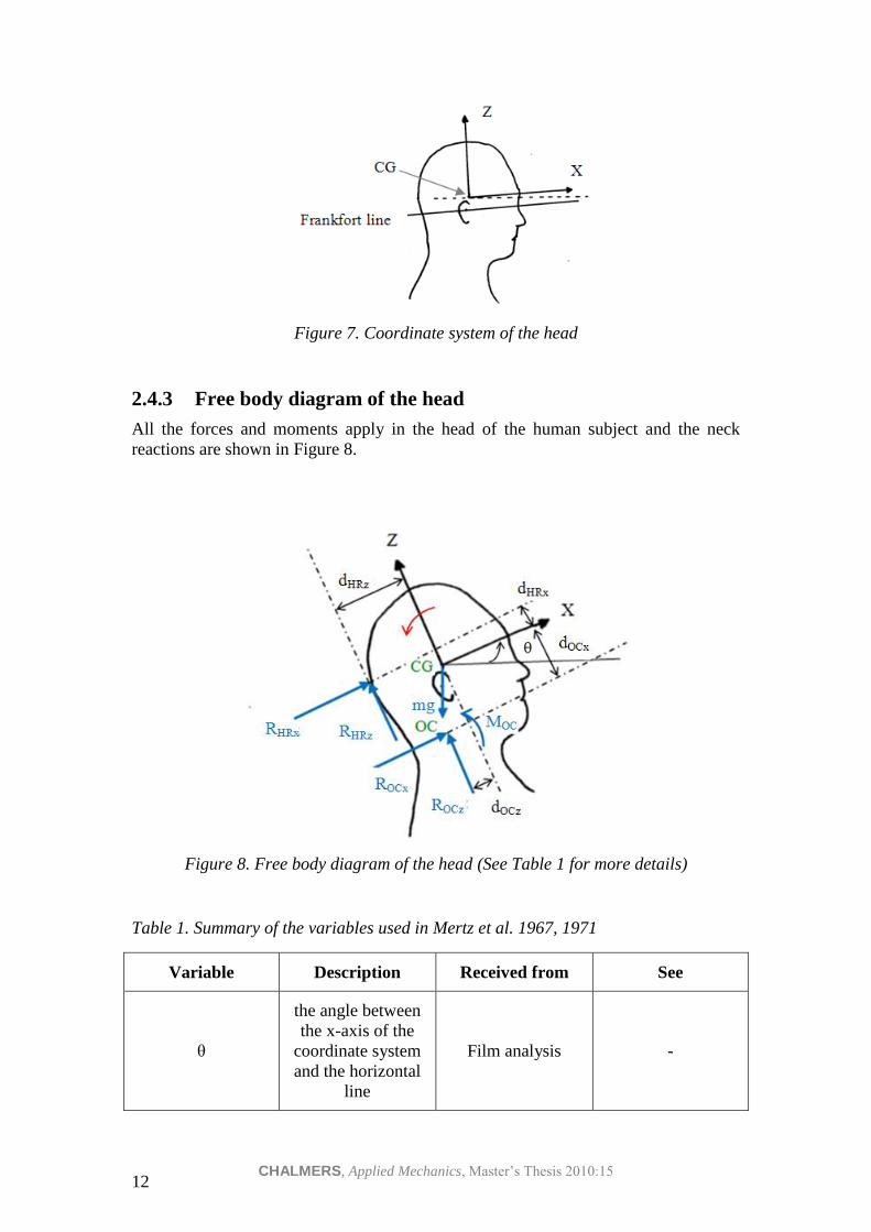
2.4.3 Free body diagram of the head
All the forces and moments apply in the head of the human subject and the neck
reactions are shown in Figure 8.
Figure 8. Free body diagram of the head (See Table 1 for more details)
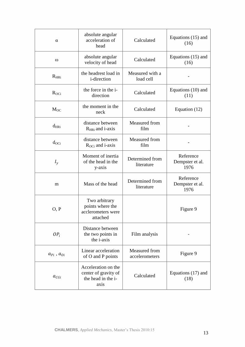
Table 1. Summary of the variables used in Mertz et al. 1967, 1971
Variable Description Received from See
θ
the angle between
the x-axis of the
coordinate system
and the horizontal
line
Film analysis -
CHALMERS, Applied Mechanics, Master’s Thesis 2010:15 13
α
absolute angular
acceleration of
head
Calculated Equations (15) and
(16)
ω absolute angular
velocity of head Calculated
Equations (15) and
(16)
RHRi the headrest load in
i-direction
Measured with a
load cell -
ROCi the force in the i-
direction Calculated
Equations (10) and
(11)
MOC the moment in the
neck Calculated Equation (12)
dHRi distance between
RHRi and i-axis
Measured from
film -
dOCi distance between
ROCi and i-axis
Measured from
film -
𝐼𝑦 Moment of inertia
of the head in the
y-axis
Determined from
literature
Reference
Dempster et al.
1976
m Mass of the head Determined from
literature
Reference
Dempster et al.
1976
O, P
Two arbitrary
points where the
acclerometers were
attached
Figure 9
𝑂𝑃𝑖
Distance between
the two points in
the i-axis
Film analysis -
𝑎𝑃𝑖 , 𝑎𝑂𝑖 Linear acceleration
of O and P points
Measured from
accelerometers Figure 9
𝑎𝐶𝐺𝑖
Acceleration on the
center of gravity of
the head in the i-
axis
Calculated Equations (17) and
(18)
CHALMERS, Applied Mechanics, Master’s Thesis 2010:15 14
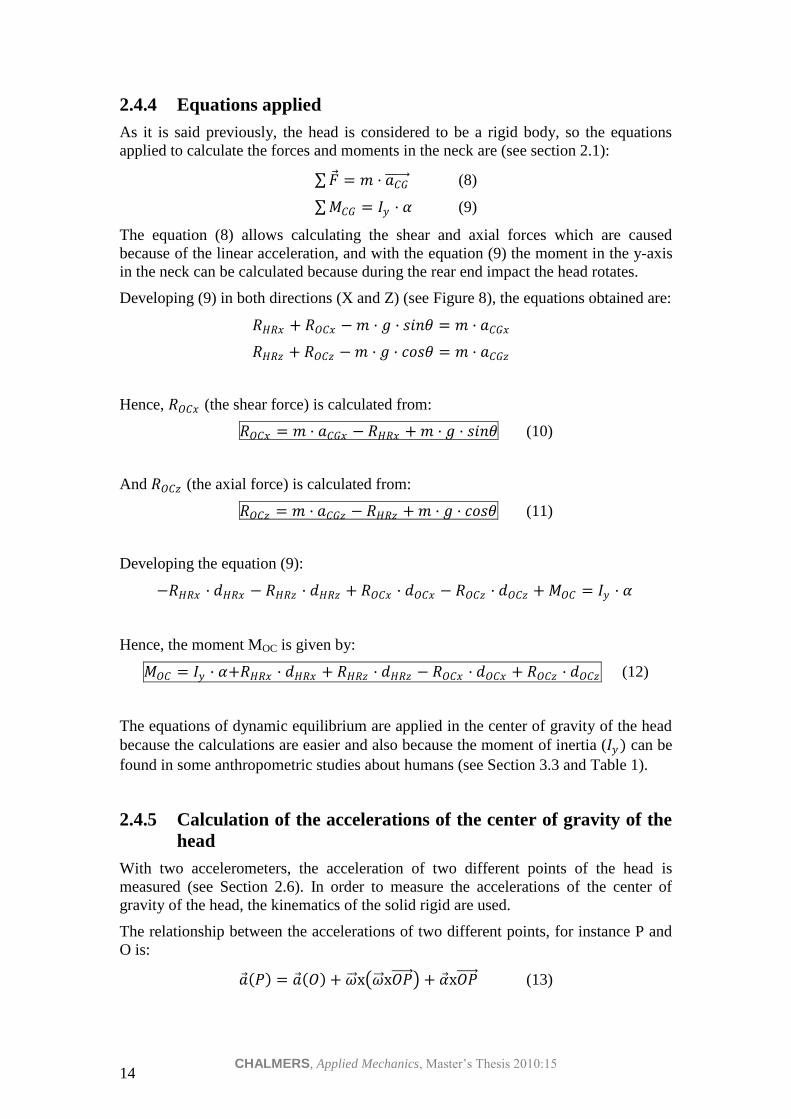
2.4.4 Equations applied
As it is said previously, the head is considered to be a rigid body, so the equations
applied to calculate the forces and moments in the neck are (see section 2.1):
𝐹 = 𝑚 · 𝑎𝐶𝐺 (8)
𝑀𝐶𝐺 = 𝐼𝑦 · 𝛼 (9)
The equation (8) allows calculating the shear and axial forces which are caused
because of the linear acceleration, and with the equation (9) the moment in the y-axis
in the neck can be calculated because during the rear end impact the head rotates.
Developing (9) in both directions (X and Z) (see Figure 8), the equations obtained are:
𝑅𝐻𝑅𝑥 + 𝑅𝑂𝐶𝑥 − 𝑚 · 𝑔 · 𝑠𝑖𝑛𝜃 = 𝑚 · 𝑎𝐶𝐺𝑥
𝑅𝐻𝑅𝑧 + 𝑅𝑂𝐶𝑧 − 𝑚 · 𝑔 · 𝑐𝑜𝑠𝜃 = 𝑚 · 𝑎𝐶𝐺𝑧
Hence, 𝑅𝑂𝐶𝑥 (the shear force) is calculated from:
𝑅𝑂𝐶𝑥 = 𝑚 · 𝑎𝐶𝐺𝑥 − 𝑅𝐻𝑅𝑥 + 𝑚 · 𝑔 · 𝑠𝑖𝑛𝜃 (10)
And 𝑅𝑂𝐶𝑧 (the axial force) is calculated from:
𝑅𝑂𝐶𝑧 = 𝑚 · 𝑎𝐶𝐺𝑧 − 𝑅𝐻𝑅𝑧 + 𝑚 · 𝑔 · 𝑐𝑜𝑠𝜃 (11)
Developing the equation (9):
−𝑅𝐻𝑅𝑥 · 𝑑𝐻𝑅𝑥 − 𝑅𝐻𝑅𝑧 · 𝑑𝐻𝑅𝑧 + 𝑅𝑂𝐶𝑥 · 𝑑𝑂𝐶𝑥 − 𝑅𝑂𝐶𝑧 · 𝑑𝑂𝐶𝑧 + 𝑀𝑂𝐶 = 𝐼𝑦 · 𝛼
Hence, the moment MOC is given by:
𝑀𝑂𝐶 = 𝐼𝑦 · 𝛼+𝑅𝐻𝑅𝑥 · 𝑑𝐻𝑅𝑥 + 𝑅𝐻𝑅𝑧 · 𝑑𝐻𝑅𝑧 − 𝑅𝑂𝐶𝑥 · 𝑑𝑂𝐶𝑥 + 𝑅𝑂𝐶𝑧 · 𝑑𝑂𝐶𝑧 (12)
The equations of dynamic equilibrium are applied in the center of gravity of the head
because the calculations are easier and also because the moment of inertia (𝐼𝑦 ) can be
found in some anthropometric studies about humans (see Section 3.3 and Table 1).
2.4.5 Calculation of the accelerations of the center of gravity of the
head
With two accelerometers, the acceleration of two different points of the head is
measured (see Section 2.6). In order to measure the accelerations of the center of
gravity of the head, the kinematics of the solid rigid are used.
The relationship between the accelerations of two different points, for instance P and
O is:
𝑎 𝑃 = 𝑎 𝑂 + 𝜔 x 𝜔 x𝑂𝑃 + 𝛼 x𝑂𝑃 (13)

CHALMERS, Applied Mechanics, Master’s Thesis 2010:15 15
The distance between these two points (𝑂𝑃 ) is known (by film analysis), the
acceleration of both points (P and O) is measured and the only unknown vectors are 𝜔 (the angular velocity of the head) and 𝛼 (the angular acceleration of the head). Then,
considering that the head has only motion in the X-Z plane, the unknown vectors are:
𝜔 = 0𝜔0
𝛼 = 0𝛼0
Therefore, the two values are obtained solving the vector equation (13):
𝑎𝑃𝑥
0𝑎𝑃𝑧
=
𝑎𝑂𝑥
0𝑎𝑂𝑧
+ 0𝜔0
x 0𝜔0
x 𝑂𝑃𝑥
0𝑂𝑃𝑧
+ 0𝛼0 x
𝑂𝑃𝑥
0𝑂𝑃𝑧
(14)
Developing equation (14):
𝑎𝑃𝑥 = 𝑎𝑂𝑥 − 𝜔2 · 𝑂𝑃𝑥 + 𝛼 · 𝑂𝑃𝑧 (15)
𝑎𝑃𝑧 = 𝑎𝑂𝑧 − 𝜔2 · 𝑂𝑃𝑧 − 𝛼 · 𝑂𝑃𝑥 (16)
Solving the previous system, α and ω can be calculated.
Once the values of α and ω are known, the same relationship between either O or P
and the center of gravity is used again to calculate the acceleration of the center of
gravity of the head.
𝑎𝐶𝐺𝑥 = 𝑎𝑂𝑥 − 𝜔2 · 𝑂𝐶𝐺𝑥 + 𝛼 · 𝑂𝐶𝐺𝑧 (17)
𝑎𝐶𝐺𝑧 = 𝑎𝑂𝑧 − 𝜔2 · 𝑂𝐶𝐺𝑧 − 𝛼 · 𝑂𝐶𝐺𝑥 (18)
With these accelerations determined, equations (10), (11) and (12) can be used to
obtain the neck reactions. The other values needed are the position of the center of
gravity of the head, the mass of the head and the mass moment of inertia which can be
determined or found in different anthropometric human studies (see Section 3); the
moment arms for the forces which can be measured from images of a camera; and the
headrest load which is also measured with a load cell.
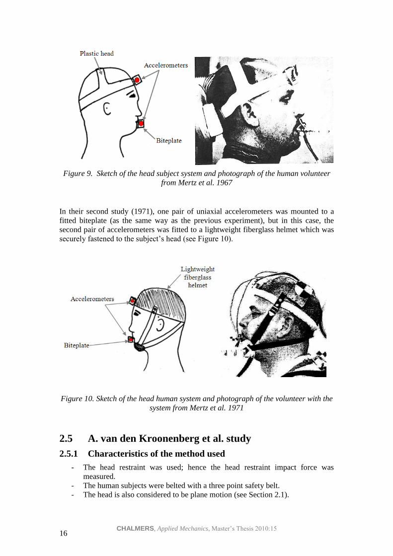
2.4.6 Human subject head instrumentation
In the first study (1967), two uniaxial accelerometers whose axes were orthogonal
were fitted at two points of the volunteer human head. One pair of accelerometers was
fitted to a plastic head and in the front head region. The other pair of accelerometers
was mounted to a fitted biteplate made of dental acrylic (see Figure 9).
CHALMERS, Applied Mechanics, Master’s Thesis 2010:15 16
Figure 9. Sketch of the head subject system and photograph of the human volunteer
from Mertz et al. 1967
In their second study (1971), one pair of uniaxial accelerometers was mounted to a
fitted biteplate (as the same way as the previous experiment), but in this case, the
second pair of accelerometers was fitted to a lightweight fiberglass helmet which was
securely fastened to the subject’s head (see Figure 10).
Figure 10. Sketch of the head human system and photograph of the volunteer with the
system from Mertz et al. 1971
2.5 A. van den Kroonenberg et al. study
2.5.1 Characteristics of the method used
- The head restraint was used; hence the head restraint impact force was
measured.
- The human subjects were belted with a three point safety belt.
- The head is also considered to be plane motion (see Section 2.1).
CHALMERS, Applied Mechanics, Master’s Thesis 2010:15 17
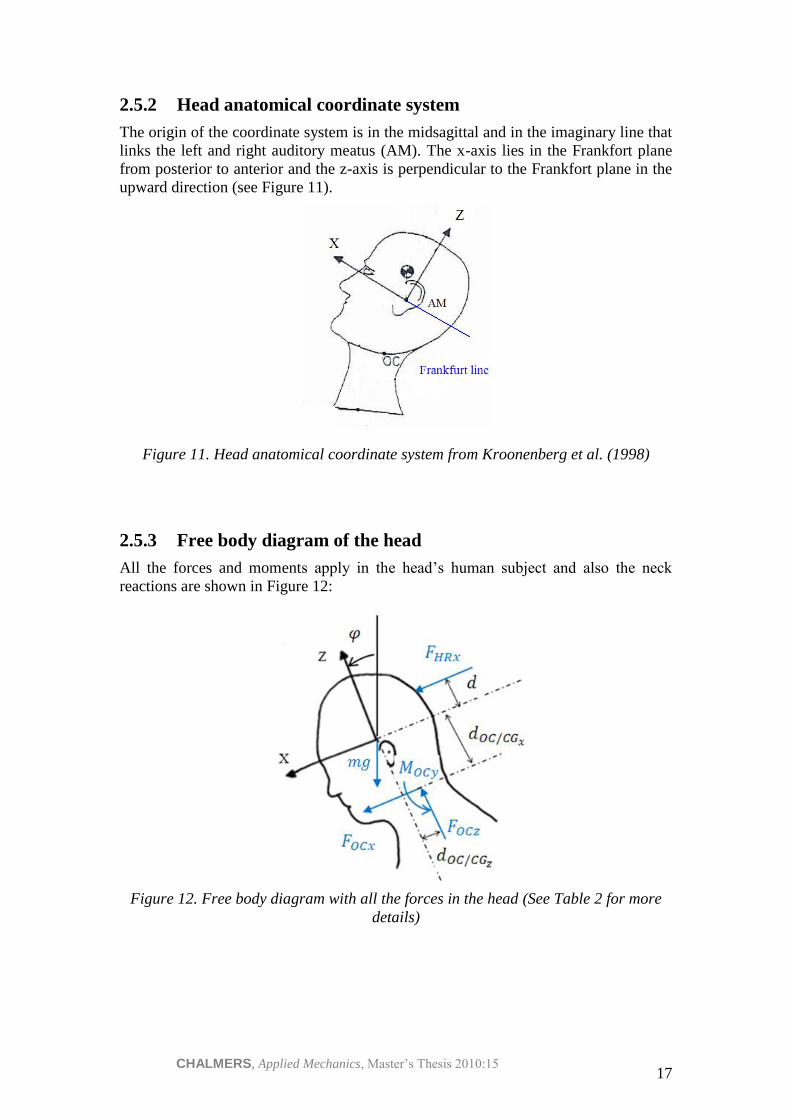
2.5.2 Head anatomical coordinate system
The origin of the coordinate system is in the midsagittal and in the imaginary line that
links the left and right auditory meatus (AM). The x-axis lies in the Frankfort plane
from posterior to anterior and the z-axis is perpendicular to the Frankfort plane in the
upward direction (see Figure 11).
Figure 11. Head anatomical coordinate system from Kroonenberg et al. (1998)
2.5.3 Free body diagram of the head
All the forces and moments apply in the head’s human subject and also the neck
reactions are shown in Figure 12:
Figure 12. Free body diagram with all the forces in the head (See Table 2 for more
details)

CHALMERS, Applied Mechanics, Master’s Thesis 2010:15 18
Table 2. Summary of the variables used in Kroonenberg et al. 1998
Variable Description Received from See
𝜑
the angle of z-axis
relative to the
vertical line
Film images -
𝐹𝑂𝐶𝑖
force at the OC
joint in the i-
direction
Calculated Equations (19) and
(20)
𝑀𝑂𝐶𝑦 the moment in the
y direction Calculated Equation (21)
𝑎𝑖
linear acceleration
of the center of
gravity of the head
in the i direction
Measured from
accelerometers Figure 13
𝛼
angular
acceleration of the
head
Measured Figure 13
𝑑
the distance
between the forces
𝐹𝐻𝑅𝑥 and 𝐹𝑂𝐶𝑥
Film images Figure 12
𝑑𝑂𝐶/𝐶𝐺𝑖
the distance
between the force
of the mass in the i
direction and 𝐹𝑂𝐶𝑖
Film images Figure 12
𝐹𝐻𝑅𝑥 the head restraint
impact forces Measured -
𝐼𝑦 the moment of
inertia in the y-axis
Determined from
literature
Reference
McConville et al.
1980 (for males)
𝑚 the mass of the
head
Determined from
literature
Reference
McConville et al.
1980 (for males)
2.5.4 Neck loads
Upper neck axial and shear force and upper neck moment were expressed in the head
anatomical coordinate system.

CHALMERS, Applied Mechanics, Master’s Thesis 2010:15 19
Since the head is considered to have motion only in the X-Z plane (see Section 2.1), it
is calculated the shear force (Fx), the axial force (Fz) and the moment in the Y-
direction. Applying equations (1) and (2) on the occipital condyles
𝐹𝑥 = 𝑚 · 𝑎𝑥
𝐹𝑧 = 𝑚 · 𝑎𝑧
𝑀𝑂𝐶𝑦 = 𝐼𝑦 · 𝛼
and observing the free body diagram of the head (see Figure 12), the resultant
equations are:
𝐹𝑂𝐶𝑥 = 𝑚 · 𝑎𝑥 − 𝑔 · 𝑠𝑖𝑛𝜑 − 𝐹𝐻𝑅𝑥 (19)
𝐹𝑂𝐶𝑧 = 𝑚 · 𝑎𝑧 − 𝑔 · 𝑐𝑜𝑠𝜑 (20)
𝑀𝑂𝐶𝑦 = 𝐼𝑦 · 𝛼 − 𝑑 · 𝐹𝐻𝑅𝑥 − 𝑑𝑂𝐶/𝐶𝐺 · 𝑚 · 𝑔 · sin 𝜑 (21)
The mass of the head, the moment of inertia in the y-axis and the position of the
center of gravity of the head can be calculated from the data of previous studies (see
Section 3). Finally, the geometrical properties (distances and angle φ) can be
measured from the film images.
2.5.5 Calculation of the accelerations of the center of gravity of the
head
The linear and angular head accelerations were measured using accelerometers. The
linear acceleration of the center of gravity of the head was measured with an
accelerometer attached in the projection of the center of gravity in one side of the
head (see Figure 13).
2.5.6 Instrumentation
Linear and angular accelerations of the head were measured. Film markers were
attached to the volunteer in order to study the motion by video images.
One accelerometer was located in the projection of the centre of gravity of the head in
the strap system in one side of the human subject. With this accelerometer, linear
acceleration was measured. Another accelerometer was attached to the head band
enabling to measure angular accelerations.
Film targets were used for recording displacements and rotations. Three film marks
were attached on the head: one in the anatomical origin, i.e. the auditory meatus, the
other in the centre of gravity and the last one in the infra orbital notch.
2.5.7 Human subject head instrumentation
Straps were tied around the chin, the forehead and the posterior part of the neck. The
head sensors were mounted in aluminium plates fixed to the straps with screws (see
Figure 13).

CHALMERS, Applied Mechanics, Master’s Thesis 2010:15 20
Figure 13. Sketch of the head sytem and photograph of the volunteer with the head
strap from Kroonenberg et al. (1998)
2.6 Japanese studies (Ono et al. 1996, 1997, 2000, 2006)
In his manifold studies, Koshiro Ono et al. used two different systems to attach all the
instrumentation needed to measure the accelerations:
- Head straps + mouthpiece (Ono et al. 1996, 1997, 2000)
- Mouthpiece (Ono et al. 2006)
2.6.1 Head strap + mouthpiece (Ono et al. 1996, 1997, 2000)
In the first studies by Ono et al. accelerometers were placed on a head strap and a
mouthpiece. The head was supposed to have planar motion (see section 2.1).
A teeth form made of a dental resin was moulded for each voluntary. One bi-axial
accelerometer was fitted in that part. The other bi-axial accelerometer was fitted in the
upper part, just in front of the forehead, with a strap around the head to fasten the
device (Figure 14).
Figure 14. Sketch
CHALMERS, Applied Mechanics, Master’s Thesis 2010:15 21
2.6.1.1 Calculation of the angular acceleration and the linear acceleration in the
center of gravity
See Section 2.4.5.
2.6.1.2 Calculation of the forces and moments in the upper neck
Using equations (1) and (2).
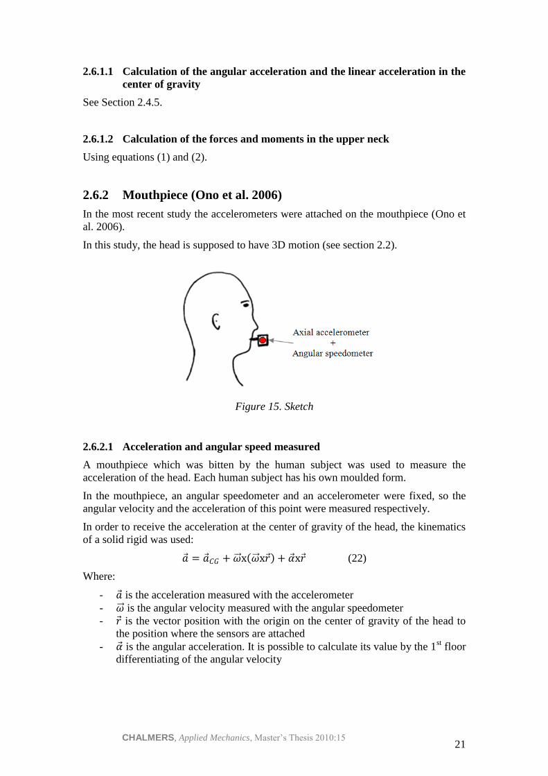
2.6.2 Mouthpiece (Ono et al. 2006)
In the most recent study the accelerometers were attached on the mouthpiece (Ono et
al. 2006).
In this study, the head is supposed to have 3D motion (see section 2.2).
Figure 15. Sketch
2.6.2.1 Acceleration and angular speed measured
A mouthpiece which was bitten by the human subject was used to measure the
acceleration of the head. Each human subject has his own moulded form.
In the mouthpiece, an angular speedometer and an accelerometer were fixed, so the
angular velocity and the acceleration of this point were measured respectively.
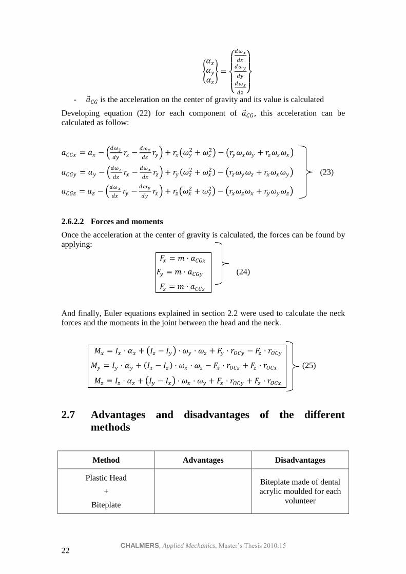
In order to receive the acceleration at the center of gravity of the head, the kinematics
of a solid rigid was used:
𝑎 = 𝑎 𝐶𝐺 + 𝜔 x 𝜔 x𝑟 + 𝛼 x𝑟 (22)
Where:
- 𝑎 is the acceleration measured with the accelerometer
- 𝜔 is the angular velocity measured with the angular speedometer
- 𝑟 is the vector position with the origin on the center of gravity of the head to
the position where the sensors are attached
- 𝛼 is the angular acceleration. It is possible to calculate its value by the 1st floor
differentiating of the angular velocity
CHALMERS, Applied Mechanics, Master’s Thesis 2010:15 22
𝛼𝑥
𝛼𝑦
𝛼𝑧
=
𝑑𝜔𝑥
𝑑𝑥𝑑𝜔𝑦
𝑑𝑦
𝑑𝜔𝑧
𝑑𝑧
- 𝑎 𝐶𝐺 is the acceleration on the center of gravity and its value is calculated
Developing equation (22) for each component of 𝑎 𝐶𝐺 , this acceleration can be
calculated as follow:
𝑎𝐶𝐺𝑥 = 𝑎𝑥 − 𝑑𝜔𝑦
𝑑𝑦𝑟𝑧 −
𝑑𝜔𝑧
𝑑𝑧𝑟𝑦 + 𝑟𝑥 𝜔𝑦
2 + 𝜔𝑧2 − 𝑟𝑦𝜔𝑥𝜔𝑦 + 𝑟𝑧𝜔𝑧𝜔𝑥
𝑎𝐶𝐺𝑦 = 𝑎𝑦 − 𝑑𝜔𝑧
𝑑𝑧𝑟𝑥 −
𝑑𝜔𝑥
𝑑𝑥𝑟𝑧 + 𝑟𝑦 𝜔𝑧
2 + 𝜔𝑥2 − 𝑟𝑧𝜔𝑦𝜔𝑧 + 𝑟𝑥𝜔𝑥𝜔𝑦 (23)
𝑎𝐶𝐺𝑧 = 𝑎𝑧 − 𝑑𝜔𝑥
𝑑𝑥𝑟𝑦 −
𝑑𝜔𝑦
𝑑𝑦𝑟𝑥 + 𝑟𝑧 𝜔𝑥
2 + 𝜔𝑦2 − 𝑟𝑥𝜔𝑧𝜔𝑥 + 𝑟𝑦𝜔𝑦𝜔𝑧
2.6.2.2 Forces and moments
Once the acceleration at the center of gravity is calculated, the forces can be found by
applying:
𝐹𝑥 = 𝑚 · 𝑎𝐶𝐺𝑥
𝐹𝑦 = 𝑚 · 𝑎𝐶𝐺𝑦 (24)
𝐹𝑧 = 𝑚 · 𝑎𝐶𝐺𝑧
And finally, Euler equations explained in section 2.2 were used to calculate the neck
forces and the moments in the joint between the head and the neck.
𝑀𝑥 = 𝐼𝑥 · 𝛼𝑥 + 𝐼𝑧 − 𝐼𝑦 · 𝜔𝑦 · 𝜔𝑧 + 𝐹𝑦 · 𝑟𝑂𝐶𝑦 − 𝐹𝑧 · 𝑟𝑂𝐶𝑦
𝑀𝑦 = 𝐼𝑦 · 𝛼𝑦 + 𝐼𝑥 − 𝐼𝑧 · 𝜔𝑥 · 𝜔𝑧 − 𝐹𝑥 · 𝑟𝑂𝐶𝑧 + 𝐹𝑧 · 𝑟𝑂𝐶𝑥 (25)
𝑀𝑧 = 𝐼𝑧 · 𝛼𝑧 + 𝐼𝑦 − 𝐼𝑥 · 𝜔𝑥 · 𝜔𝑦 + 𝐹𝑥 · 𝑟𝑂𝐶𝑦 + 𝐹𝑧 · 𝑟𝑂𝐶𝑥
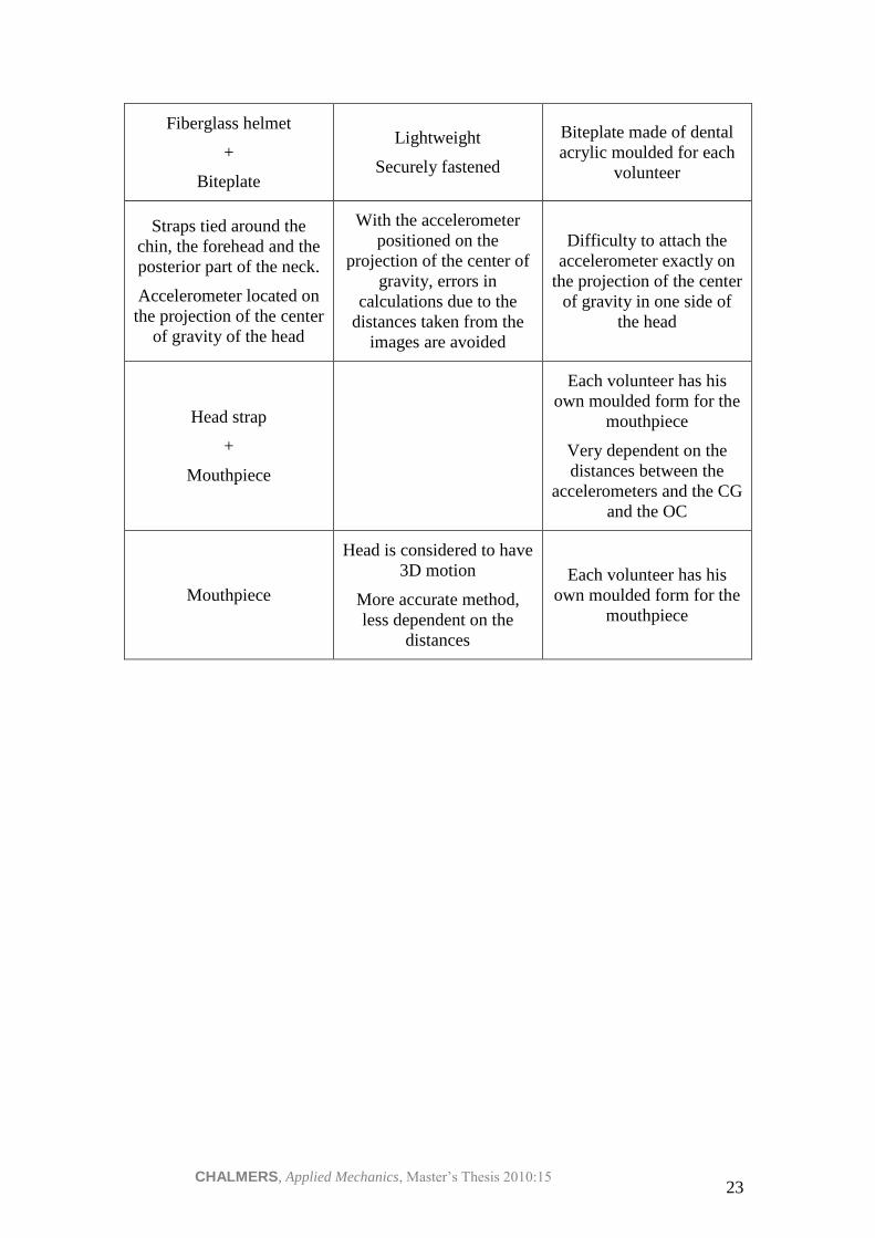
2.7 Advantages and disadvantages of the different
methods
Method Advantages Disadvantages
Plastic Head
+
Biteplate
Biteplate made of dental
acrylic moulded for each
volunteer
CHALMERS, Applied Mechanics, Master’s Thesis 2010:15 23
Fiberglass helmet
+
Biteplate
Lightweight
Securely fastened
Biteplate made of dental
acrylic moulded for each
volunteer
Straps tied around the
chin, the forehead and the
posterior part of the neck.
Accelerometer located on
the projection of the center
of gravity of the head
With the accelerometer
positioned on the
projection of the center of
gravity, errors in
calculations due to the
distances taken from the
images are avoided
Difficulty to attach the
accelerometer exactly on
the projection of the center
of gravity in one side of
the head
Head strap
+
Mouthpiece
Each volunteer has his
own moulded form for the
mouthpiece
Very dependent on the
distances between the
accelerometers and the CG
and the OC
Mouthpiece
Head is considered to have
3D motion
More accurate method,
less dependent on the
distances
Each volunteer has his
own moulded form for the
mouthpiece
CHALMERS, Applied Mechanics, Master’s Thesis 2010:15 24
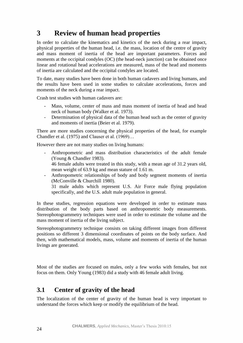
3 Review of human head properties
In order to calculate the kinematics and kinetics of the neck during a rear impact,
physical properties of the human head, i.e. the mass, location of the centre of gravity
and mass moment of inertia of the head are important parameters. Forces and
moments at the occipital condyles (OC) (the head-neck junction) can be obtained once
linear and rotational head accelerations are measured, mass of the head and moments
of inertia are calculated and the occipital condyles are located.
To date, many studies have been done in both human cadavers and living humans, and
the results have been used in some studies to calculate accelerations, forces and
moments of the neck during a rear impact.
Crash test studies with human cadavers are:
- Mass, volume, center of mass and mass moment of inertia of head and head
neck of human body (Walker et al. 1973).
- Determination of physical data of the human head such as the center of gravity
and moments of inertia (Beier et al. 1979).
There are more studies concerning the physical properties of the head, for example
Chandler et al. (1975) and Clauser et al. (1969)…
However there are not many studies on living humans:
- Anthropometric and mass distribution characteristics of the adult female
(Young & Chandler 1983).
46 female adults were treated in this study, with a mean age of 31.2 years old,
mean weight of 63.9 kg and mean stature of 1.61 m.
- Anthropometric relationships of body and body segment moments of inertia
(McConville & Churchill 1980).
31 male adults which represent U.S. Air Force male flying population
specifically, and the U.S. adult male population in general.
In these studies, regression equations were developed in order to estimate mass
distribution of the body parts based on anthropometric body measurements.
Stereophotogrammetry techniques were used in order to estimate the volume and the
mass moment of inertia of the living subject.
Stereophotogrammetry technique consists on taking different images from different
positions so different 3 dimensional coordinates of points on the body surface. And
then, with mathematical models, mass, volume and moments of inertia of the human
livings are generated.
Most of the studies are focused on males, only a few works with females, but not
focus on them. Only Young (1983) did a study with 46 female adult living.
3.1 Center of gravity of the head
The localization of the center of gravity of the human head is very important to
understand the forces which keep or modify the equilibrium of the head.
CHALMERS, Applied Mechanics, Master’s Thesis 2010:15 25
In the human subjects, the center of gravity of the head is located just in front of the
occipital condyles.
It should have be carefully when extrapolate conclusions from studies on cadavers to
living human subjects, because the localization of the center of gravity may change
slightly due to the movement of the brain and the alteration of the blood flow in the
living humans.
There are many studies both in cadavers and in living humans as mentioned above.
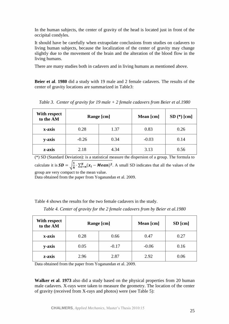
Beier et al. 1980 did a study with 19 male and 2 female cadavers. The results of the
center of gravity locations are summarized in Table3:
Table 3. Center of gravity for 19 male + 2 female cadavers from Beier et al.1980
With respect
to the AM Range [cm] Mean [cm] SD (*) [cm]
x-axis 0.28 1.37 0.83 0.26
y-axis -0.26 0.34 -0.03 0.14
z-axis 2.18 4.34 3.13 0.56
(*) SD (Standard Deviation): is a statistical measure the dispersion of a group. The formula to
calculate it is 𝑺𝑫 = 𝟏
𝑵· 𝒙𝒊 − 𝑴𝒆𝒂𝒏 𝟐𝑵
𝒊=𝒏 . A small SD indicates that all the values of the
group are very compact to the mean value.
Data obtained from the paper from Yoganandan et al. 2009.
Table 4 shows the results for the two female cadavers in the study.
Table 4. Center of gravity for the 2 female cadavers from by Beier et al.1980
With respect
to the AM Range [cm] Mean [cm] SD [cm]
x-axis 0.28 0.66 0.47 0.27
y-axis 0.05 -0.17 -0.06 0.16
z-axis 2.96 2.87 2.92 0.06
Data obtained from the paper from Yoganandan et al. 2009.
Walker et al. 1973 also did a study based on the physical properties from 20 human
male cadavers. X-rays were taken to measure the geometry. The location of the center
of gravity (received from X-rays and photos) were (see Table 5):

CHALMERS, Applied Mechanics, Master’s Thesis 2010:15 26
Table 5. Center of gravity of the head from Walker et al. 1973
With respect
to the AM X-Ray [cm] Photo [cm]
x-axis 0.91 1.49
z-axis 2.22 2.448
Young et al. 1983 did a study with 46 adult living female subjects. In this case, the
authors gave the location of the center of volume of the head (see Table 6).
Table 6. Center of volume of the head of 46 female subjects from Young et al.1983
With respect
to the AM
Range [cm] Mean [cm] SD [cm]
x-axis -2.43 0.05 -1.08 0.53
y-axis -0.6 0.84 0.01 0.35
z-axis 2.24 4.79 3.42 0.45
In the study the relationship between the center of volume and the center of gravity is
non-well explained. The authors wrote that “the center of volume as reported in this
study is not coincident with the center of mass of the head”, but they also stated that
for the purpose of their study (establish the relationship between human body size and
its mass distribution properties) the use of the center of volume instead the exactly
position of the center of mass is believed to be valid.
In all the papers by Koshiro Ono et al. 1996, 1997, 2000, 2006:
- Cervical injury mechanism based on the analysis of human cervical vertebral
motion and head-neck-torso kinematics during low speed rear impacts (1997)
- Analysis of seat properties on human cervical vertebral motion in low-speed
rear-end impacts (2000)
- Prediction of neck injury risk based on the analysis of localized cervical
vertebral motion of human volunteers during low-speed rear impacts (2006)
Where the forces and the moments were calculated on experiments with human
subjects, the position of the center of gravity of the head was situated 5 mm in the
forward direction from the auditory meatus and 20 mm on the vertical line of the
Frankfort line.

CHALMERS, Applied Mechanics, Master’s Thesis 2010:15 27
The position of the center of gravity of the head in the 5th
percentile female dummy
(small female) which has been taken, with respect to the auditory meatus is according
to Robbins et al. 1983:
- X= -2mm
- Y= 0mm
- Z= 33mm
3.1.1 Summary
In Table 7 all the data to locate the center of gravity relative to the auditory meatus is
summarized.
Table 7. Summary of the different studies for the location of the center of gravity
relative to the AM [cm]
Author x-axis y-axis z-axis
Beier et al. 1980 –
19 males + 2
females cadavers
0.83 -0.03 3.13
Beier et al. 1980 –
2 females cadavers 0.47 -0.06 2.92
Walker et al. 1973
– 20 males
cadavers (Photo)
1.49 - 2.488
Walker et al. 1973
– 20 males (X-
Ray)
0.91 - 2.22
Young et al. 1983 –
46 living females -1.08 0.01 3.42
Ono – used in his
studies (males) 0.5 0 2
5th
percentile
female dummy -0.2 0 3.3
3.2 Mass of the head
In the study by Walker et al. (1973), the mean head mass for the 20 male cadavers
was 4.4 ±0.6 kg.

CHALMERS, Applied Mechanics, Master’s Thesis 2010:15 28
In the Beier et al. (1980) study the mean head mass was 4.324 kg with a SD of 0.395
kg. (for 19 males + 2 females).
The average head mass for the 2 females in the study was 4.125 ±0.6 kg
Young et al. (1983) did not calculate the mass of the head directly, but in their study
the mean volume of the head was calculated, as well as regression equations to predict
the volume of the head of the females.
The range of the head volume of the 46 living adult females was 3386 – 4514 cm3,
with a mean value of 3.894 cm3 (SD= 267 cm
3). The regression equations based on
stature and height (easy to measure these values in living humans) and using other
measurements of body sizes of the human head are (see section 3.3.1 for descriptions
of the anthropometric measurements):
Table 8. Regression equations for the volume of the female head by Young et al.
(1983) (See Section 3.3.1 for the anthropometric measurements)
R (*) SE EST
(**)
−1.25 ∗ 𝑆𝑡𝑎𝑡𝑢𝑟𝑒 + 4.45 ∗ 𝑊𝑒𝑖𝑔𝑡 + 3469 0.450 6.3%
147.05 ∗ 𝐻𝑒𝑎𝑑 𝑐𝑖𝑟𝑐. −4161.23 0.661 5.2%
108.73 ∗ 𝐻𝑒𝑎𝑑 𝑐𝑖𝑟𝑐. +137.28 ∗ 𝐻𝑒𝑎𝑑 𝑒𝑖𝑔𝑡 − 4202.24 0.754 4.6%
132.85 ∗ 𝐻𝑒𝑎𝑑 𝑐𝑖𝑟𝑐. +163.75 ∗ 𝐻𝑒𝑎𝑑 𝑒𝑖𝑔𝑡 − 13.73 ∗ 𝑆𝑡𝑎𝑡𝑢𝑟𝑒− 3722.51 0.799 4.3%
(*) R: Multiple correlation coefficient. It’s a statistical measure which measure the strength
between the predictive variable and the variable used in the regression equations. The closer
R is to one, the stronger is the linear association.
(**) SE EST: Standard error of estimate. It’s a measure of the accuracy of predictions given
by a regression line. It is given as a percent of the predicted variable mean value.
In order to obtain the regression equations, BMD (Biomedical Computer Program)
stepwise regression computer program, and the anthropometric variables, was used to
better predict the head properties.
Once the head volume is estimated, the mass of the head can be easily calculated by
using the concept of specific gravity (SG) (the ratio of a density of a sample of the
human to the density of the water):
𝑆𝐺 =𝜌
𝜌𝐻2𝑂 (26)
Where:
- 𝜌 is the density of the human body
- 𝜌𝐻2𝑂 is the density of the water, which equals to 1g/cm3
- SG is the specific gravity
CHALMERS, Applied Mechanics, Master’s Thesis 2010:15 29
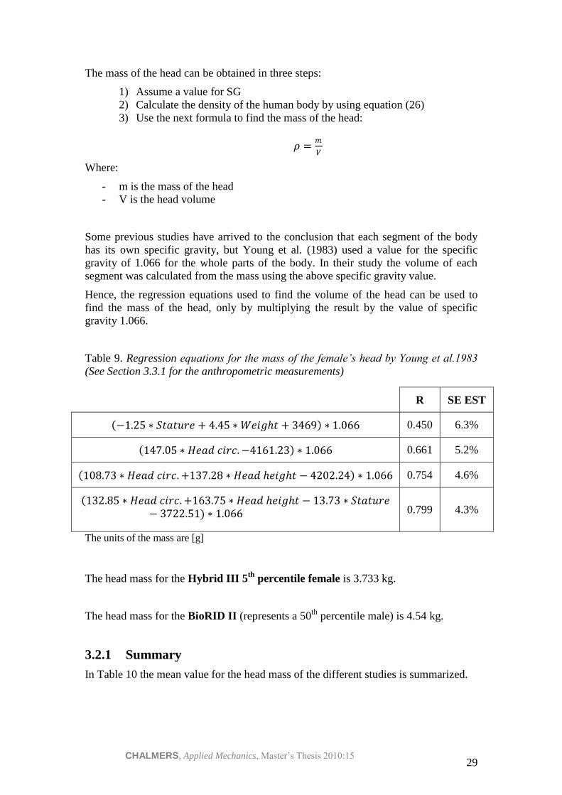
The mass of the head can be obtained in three steps:
1) Assume a value for SG
2) Calculate the density of the human body by using equation (26)
3) Use the next formula to find the mass of the head:
𝜌 =𝑚
𝑉
Where:
- m is the mass of the head
- V is the head volume
Some previous studies have arrived to the conclusion that each segment of the body
has its own specific gravity, but Young et al. (1983) used a value for the specific
gravity of 1.066 for the whole parts of the body. In their study the volume of each
segment was calculated from the mass using the above specific gravity value.
Hence, the regression equations used to find the volume of the head can be used to
find the mass of the head, only by multiplying the result by the value of specific
gravity 1.066.
Table 9. Regression equations for the mass of the female’s head by Young et al.1983
(See Section 3.3.1 for the anthropometric measurements)
R SE EST
−1.25 ∗ 𝑆𝑡𝑎𝑡𝑢𝑟𝑒 + 4.45 ∗ 𝑊𝑒𝑖𝑔𝑡 + 3469 ∗ 1.066 0.450 6.3%
147.05 ∗ 𝐻𝑒𝑎𝑑 𝑐𝑖𝑟𝑐. −4161.23 ∗ 1.066 0.661 5.2%
108.73 ∗ 𝐻𝑒𝑎𝑑 𝑐𝑖𝑟𝑐. +137.28 ∗ 𝐻𝑒𝑎𝑑 𝑒𝑖𝑔𝑡 − 4202.24 ∗ 1.066 0.754 4.6%
132.85 ∗ 𝐻𝑒𝑎𝑑 𝑐𝑖𝑟𝑐. +163.75 ∗ 𝐻𝑒𝑎𝑑 𝑒𝑖𝑔𝑡 − 13.73 ∗ 𝑆𝑡𝑎𝑡𝑢𝑟𝑒− 3722.51 ∗ 1.066 0.799 4.3%
The units of the mass are [g]
The head mass for the Hybrid III 5th
percentile female is 3.733 kg.
The head mass for the BioRID II (represents a 50th
percentile male) is 4.54 kg.
3.2.1 Summary
In Table 10 the mean value for the head mass of the different studies is summarized.

CHALMERS, Applied Mechanics, Master’s Thesis 2010:15 30
Table 10. Summary of the different studies for mass of the female’s head
Author N (Females) N (Males) Subjects Mean mass
[kg]
Walker et al. (1973) - 20 Cadavers 4.4
Beier et al. (1980) 2 19 Cadavers 4.324
Beier et al. (1980) 2 - Cadavers 4.125
Young et al. (1983)
(*) 46 - Volunteers 4.15
Hybrid III 5th
percentile female - - Dummy 3.733
BioRID II (50th
percentile male) - - Dummy 4.54
(*) The mass is calculated from the volume of the head
3.3 Moment of inertia of the head
From Walker et al. 1973 study (20 male cadavers) the mean moment of inertia in the
y-axis was 233 ±37 kg·cm2. In the other axis, they weren’t calculated.
One observation given by the same authors of this paper is that the position of the
center of gravity of the head seems to be more reliable than the value of the mass
moment of inertia.
From Beier et al. 1980, the moments of inertia of the head (19 males + 2 females)
were calculated in all directions. The table below summarized the min. and max.
values and also the mean.
Table 11. Moments of inertia by Beier et al.1980
Range [kg·cm2] Mean [kg·cm
2] SD
𝑰𝒙 136 274 205.9 34.6
𝑰𝒚 159 298 223.4 34.4
𝑰𝒛 110 198 148.4 25.5
Data from Beier indicate that exist a good correlation (R2=0.77, 0.93, 0.74 for Ix, Iy, Iz
respectively) between head mass and the principal moments of inertia of the head.

CHALMERS, Applied Mechanics, Master’s Thesis 2010:15 31
Hence, predictive equations for mass moment of inertia as a function of the head mass
were proposed by the author. These are the following equations:
𝐼𝑥 = 11.746 ∗ 𝐻𝑒𝑎𝑑 𝑤𝑒𝑖𝑔𝑡 − 40.964
𝐼𝑦 = 12.788 ∗ 𝐻𝑒𝑎𝑑 𝑤𝑒𝑖𝑔𝑡 − 44.826
𝐼𝑧 = 8.4519 ∗ 𝐻𝑒𝑎𝑑 𝑤𝑒𝑖𝑔𝑡 − 29.386
The head weight is measured in lbs, and I is the mass moment of inertia of the head in
lb·in2.
Also from Young et al. 1983 study (46 living females), regression equations were
extracted which can be used for predicting the moment of inertia of the head. It is
possible because this study demonstrates that body size and moments of inertia are
related.
On these regression equations, stature and weight are used because of the facility to
measure these values on a human subject, but also the most highly correlated
variables are used.
The whole regression equations for the three axes are summarized in Table 12:
Table 12. Regression equations for the moment of inertia of the head in the x-axis
from Young et al. 1983 (See Section 3.3.1 for the anthropometric measurements)
Head x-moment of inertia
R SE
EST
𝐼𝑥
−384 ∗ 𝑆𝑡𝑎𝑡𝑢𝑟𝑒 + 476 ∗ 𝑊𝑒𝑖𝑔𝑡 + 155137 0.419 17.1%
21363 ∗ 𝐻𝑒𝑎𝑑 𝑒𝑖𝑔𝑡 − 172855 0.567 15.4%
16909 ∗ 𝐻𝑒𝑎𝑑 𝑒𝑖𝑔𝑡 + 17129 ∗ 𝐻𝑒𝑎𝑑 𝑏𝑟𝑒𝑎𝑑𝑡 − 353147 0.609 14.9%
21363 ∗ 𝐻𝑒𝑎𝑑 𝑒𝑖𝑔𝑡 + 17142 ∗ 𝐻𝑒𝑎𝑑 𝑏𝑟𝑒𝑎𝑑𝑡 − 723 ∗ 𝑆𝑡𝑎𝑡𝑢𝑟𝑒− 271345 0.624 14.9%
Head y-moment of inertia R SE
EST
𝐼𝑦
−25 ∗ 𝑆𝑡𝑎𝑡𝑢𝑟𝑒 + 357 ∗ 𝑊𝑒𝑖𝑔𝑡 + 143627 0.409 11.8%
12704 ∗ 𝐻𝑒𝑎𝑑 𝑐𝑖𝑟𝑐. −505983 0.635 9.9%
9784 ∗ 𝐻𝑒𝑎𝑑 𝑐𝑖𝑟𝑐. +10461 ∗ 𝐻𝑒𝑎𝑑 𝑒𝑖𝑔𝑡 − 509109 0.706 9.2%
11702 ∗ 𝐻𝑒𝑎𝑑 𝑐𝑖𝑟𝑐. +125666 ∗ 𝐻𝑒𝑎𝑑 𝑒𝑖𝑔𝑡 − 1092 ∗ 𝑆𝑡𝑎𝑡𝑢𝑟𝑒− 470950 0.743 8.8%
CHALMERS, Applied Mechanics, Master’s Thesis 2010:15 32
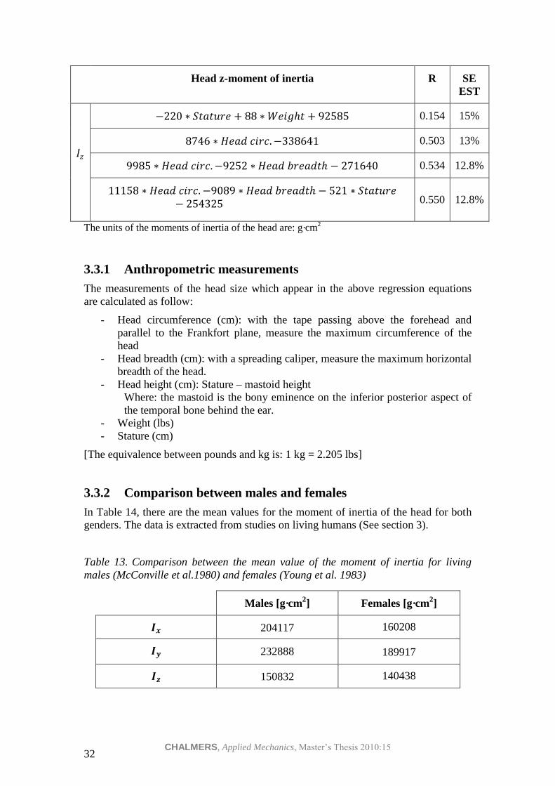
Head z-moment of inertia R SE
EST
𝐼𝑧
−220 ∗ 𝑆𝑡𝑎𝑡𝑢𝑟𝑒 + 88 ∗ 𝑊𝑒𝑖𝑔𝑡 + 92585 0.154 15%
8746 ∗ 𝐻𝑒𝑎𝑑 𝑐𝑖𝑟𝑐. −338641 0.503 13%
9985 ∗ 𝐻𝑒𝑎𝑑 𝑐𝑖𝑟𝑐. −9252 ∗ 𝐻𝑒𝑎𝑑 𝑏𝑟𝑒𝑎𝑑𝑡 − 271640 0.534 12.8%
11158 ∗ 𝐻𝑒𝑎𝑑 𝑐𝑖𝑟𝑐. −9089 ∗ 𝐻𝑒𝑎𝑑 𝑏𝑟𝑒𝑎𝑑𝑡 − 521 ∗ 𝑆𝑡𝑎𝑡𝑢𝑟𝑒− 254325 0.550 12.8%
The units of the moments of inertia of the head are: g·cm2
3.3.1 Anthropometric measurements
The measurements of the head size which appear in the above regression equations
are calculated as follow:
- Head circumference (cm): with the tape passing above the forehead and
parallel to the Frankfort plane, measure the maximum circumference of the
head
- Head breadth (cm): with a spreading caliper, measure the maximum horizontal
breadth of the head.
- Head height (cm): Stature – mastoid height
Where: the mastoid is the bony eminence on the inferior posterior aspect of
the temporal bone behind the ear.
- Weight (lbs)
- Stature (cm)
[The equivalence between pounds and kg is: 1 kg = 2.205 lbs]
3.3.2 Comparison between males and females
In Table 14, there are the mean values for the moment of inertia of the head for both
genders. The data is extracted from studies on living humans (See section 3).
Table 13. Comparison between the mean value of the moment of inertia for living
males (McConville et al.1980) and females (Young et al. 1983)
Males [g·cm2] Females [g·cm
2]
𝑰𝒙 204117 160208
𝑰𝒚 232888 189917
𝑰𝒛 150832 140438

CHALMERS, Applied Mechanics, Master’s Thesis 2010:15 33
3.4 Position of the occipital condyle
The location of the occipital condyle relative to the coordinate reference system of the
head (see Figure III) used in previous studies (Yoganandan et al. 2009, Wismans et al.
1986) for the calculation of the dynamics of the neck is:
- x= -11 mm
- y= 0 mm
- z= -26 mm
In such study, the location of occipital condyles are assumed to be subjects
independents, instead of locate this point for each volunteer as it has been done in
most recent experiments with volunteers. The position of the occipital condyles was
the average values based on human volunteer data.
Another location for the occipital condyles (OC) relative to the coordinate reference
system of the head (see Figure III) extracted from literature (Yoganandan et al. 2009,
Plaga et al. 2005) is: 8.89 mm anterior and 31.75 mm inferior to the origin of
anatomic coordinate system reference (see Figure III).
- x= -8.89 mm
- y= 0 mm
- z= -31.75 mm
Another position for the occipital condyles relative to the coordinate reference system
of the head (see Figure III), in that case specific for small females, which has been
taken when constructing the respective dummy (5th
percentile female dummy Hybrid),
is (Robbins et al. 1983):
- x= -11 mm
- y= 0 mm
- z= -25 mm
The anthropometric characteristics of the small female are:
- Stature: 151 cm
- Weight: 47 kg
The position of the occipital condyles (in this case, the position of the occipital
condyles is given with respect to the center of gravity instead of the auditory meatus)
in the BioRID II is:
- x= -19 mm
- y= 0 mm
- z= -51 mm
The author of the present study has been investigating another way to find out the
position of the occipital condyles in human without using X-ray, but the research has
been unsuccessful.
CHALMERS, Applied Mechanics, Master’s Thesis 2010:15 34
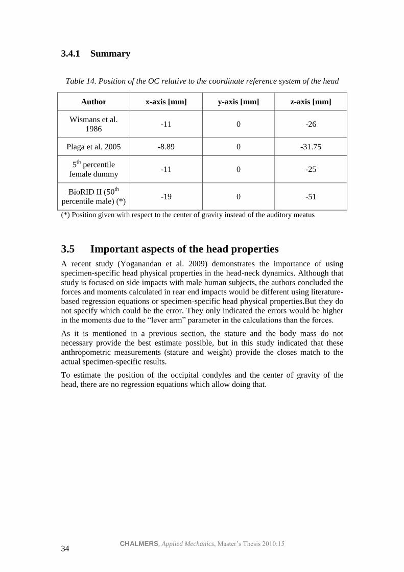
3.4.1 Summary
Table 14. Position of the OC relative to the coordinate reference system of the head
Author x-axis [mm] y-axis [mm] z-axis [mm]
Wismans et al.
1986 -11 0 -26
Plaga et al. 2005 -8.89 0 -31.75
5th
percentile
female dummy -11 0 -25
BioRID II (50th
percentile male) (*) -19 0 -51
(*) Position given with respect to the center of gravity instead of the auditory meatus
3.5 Important aspects of the head properties
A recent study (Yoganandan et al. 2009) demonstrates the importance of using
specimen-specific head physical properties in the head-neck dynamics. Although that
study is focused on side impacts with male human subjects, the authors concluded the
forces and moments calculated in rear end impacts would be different using literature-
based regression equations or specimen-specific head physical properties.But they do
not specify which could be the error. They only indicated the errors would be higher
in the moments due to the “lever arm” parameter in the calculations than the forces.
As it is mentioned in a previous section, the stature and the body mass do not
necessary provide the best estimate possible, but in this study indicated that these
anthropometric measurements (stature and weight) provide the closes match to the
actual specimen-specific results.
To estimate the position of the occipital condyles and the center of gravity of the
head, there are no regression equations which allow doing that.

CHALMERS, Applied Mechanics, Master’s Thesis 2010:15 35
4 IMT40
IMT40 is a new sensor market by the company IMEGO.
IMEGO is a Swedish company founded in 1999. It has a great experience in sensors,
since IMEGO has launched many.
IMEGO does not have any experience with volunteer experiments, but its products
have been used by many cars manufactures on dummies, allowing them to obtain
certain data and improve the vehicle safety.
IMT40 is designed for measuring all details of rapid, violent motions. The product
includes the sensor and the PC software for the calculations.
Such product measures:
- Position
- Velocity
- Acceleration
- Attitude/angular rate
- Angular acceleration
One good advantage of the new sensor is that with its software the accelerations of
different points of the solid can be calculated in an easy way. Another advantage is
the fact that the frequency in which the information can be taken could be very high
(up to 7.8 kHz); thus, each second lots of information are recorded, so the errors
decrease.
Other characteristics of the sensor are:
- Dimensions: 64x38.2x28.2 mm3
- Weight: < 100g
- Cost: around 400 000 SEK
The information was found in the webpage of the company: www.imego.com and
also from and a personal interview with Kenneth Malmström and Peter Björkholm,
workers on IMEGO.
Figure 16. View of the IMT40. Picture extracted from www.imego.com

CHALMERS, Applied Mechanics, Master’s Thesis 2010:15 36
The company does not sell any additional equipment to fix the sensor on the volunteer
head, but they are willing to help in the construction of the adequate head rig if it’s
necessary.

CHALMERS, Applied Mechanics, Master’s Thesis 2010:15 37
5 Sensitivity regarding the position of the OC
The objective of the following section is to evaluate the error in the upper neck loads
when the position of the occipital condyle is varied.
Data recorded from one male volunteer in a rear end impact is used to estimate the
sensitivity regarding the position of the OC. The data was provided by Johan
Davidsson from his experiments at the end of 90s.
The characteristics of the experiment were:
- No head restraint was used
- No tension, in a relax position
- Low velocity (8 km/h)
- The method used to fix the accelerometers was a head strap + mouthpiece (see
Figure 17 and section 2.6.1)
The characteristics of the male volunteer were:
- Age: 22 years
- Mass of the head: 4.24 kg. (Estimated from McConville et al. 1980)
- Moment of inertia of the head: 2.22 · 105 𝑔 · 𝑐𝑚2 . (Estimated from
McConville et al. 1980)
- Location of the CG relative to the coordinate reference system of the head (see
Figure III):
𝑑𝑥 = 5 𝑚𝑚
𝑑𝑧 = 20 𝑚𝑚
The position of the CG is the same as in Ono et al. studies.
- Location of the OC relative to the coordinate reference system of the head (see
Figure III):
𝑑𝑥 = −8 𝑚𝑚
𝑑𝑧 = −35 𝑚𝑚
Extracted from X-rays of the volunteer’s head.
- Distances between accelerometers/center of gravity/occipital condyles: see
Figure 17.

CHALMERS, Applied Mechanics, Master’s Thesis 2010:15 38
Figure 17. Volunteer head with the position of the 2 uni-axial accelerometers, the
occipital condyle and the center of gravity and the distances between these points
From the experiment, linear acceleration from the upper and lower position was
measured in x- and z- direction.
As it can be observed from section 2, the location of the occipital condyles only
affects the bending moment in the upper neck; the loads are not influence by such
point. Hence, in this part is only studied the error in the moment.
To calculate the bending moment with the linear acceleration measured, the next steps
are followed:
1) Equations (15) and (16) are used to calculate the head angular acceleration and
the head angular velocity.
𝑎𝐿𝑥 = 𝑎𝑈𝑥 − 𝜔2 · 𝑈𝐿𝑥 + 𝛼 · 𝑈𝐿𝑧
𝑎𝐿𝑧 = 𝑎𝑈𝑧 − 𝜔2 · 𝑈𝐿𝑧 − 𝛼 · 𝑈𝐿𝑥 Where (see Figure 17):
𝑎𝐿𝑥 , 𝑎𝑈𝑥 , 𝑎𝐿𝑧 , 𝑎𝑈𝑧 is the acceleration measured
𝑈𝐿𝑥 = 0 is the distance between the accelerometers in the x-direction
𝑈𝐿𝑧 = 130 𝑚𝑚 is the distance between the accelerometers in the z-
direction
2) Acceleration of the center of gravity is calculated with equation (13) applied in
the upper point (U)
𝑎 𝐶𝐺 = 𝑎 𝑈 + 𝜔 x 𝜔 x𝑈𝐶𝐺 + 𝛼 x𝑈𝐶𝐺

CHALMERS, Applied Mechanics, Master’s Thesis 2010:15 39
Developing the last equation:
𝑎𝐶𝐺𝑥 = 𝑎𝑈𝑥 − 𝜔2 · 𝑈𝐶𝐺𝑥𝑥 + 𝛼 · 𝑈𝐶𝐺𝑥𝑧
𝑎𝐶𝐺𝑧 = 𝑎𝑈𝑧 − 𝜔2 · 𝑈𝐶𝐺𝑧𝑧 − 𝛼 · 𝑈𝐶𝐺𝑧𝑥 Where:
𝑈𝐶𝐺𝑥𝑥 = −152 𝑚𝑚 is the distance in the x-direction between the x-
accelerometer in the upper part and the center of gravity
𝑈𝐶𝐺𝑥𝑧 = −65 𝑚𝑚 is the distance in the z-direction between the x-
accelerometer in the upper part and the center of gravity
𝑈𝐶𝐺𝑧𝑧 = −74 𝑚𝑚 is the distance in the z-direction between the z-
accelerometer in the upper part and the center of gravity
𝑈𝐶𝐺𝑧𝑥 = −152 𝑚𝑚 is the distance in the x-direction between the z-
accelerometer in the upper part and the center of gravity
3) Then using equation (1) the forces are calculated:
𝐹𝑥 = 𝑚 · 𝑎𝐶𝐺𝑥
𝐹𝑧 = 𝑚 · 𝑎𝐶𝐺𝑧
4) And finally the bending moment is calculated:
𝑀𝑦 = 𝐼𝑦 · 𝛼 − 𝐹𝑥 · 𝑑𝑧 − 𝐹𝑧 · 𝑑𝑥
Where:
𝑑𝑧 is the distance between the center of gravity of the head and the
occipital condyles in the z-direction
𝑑𝑥 is the distance between the center of gravity of the head and the
occipital condyles in the x-direction
The graph with the real position of the occipital condyle ( 𝑑𝑧 = 20 + 35 𝑚𝑚, 𝑑𝑥 =5 + 8 𝑚𝑚) of the volunteer is:
Figure 18.Neck moment in the OC of the volunteer
-5
-4
-3
-2
-1
0
1
2
3
4
5
6
0 100 200 300 400
Neck moment
Neck moment [Nm]
CHALMERS, Applied Mechanics, Master’s Thesis 2010:15 40
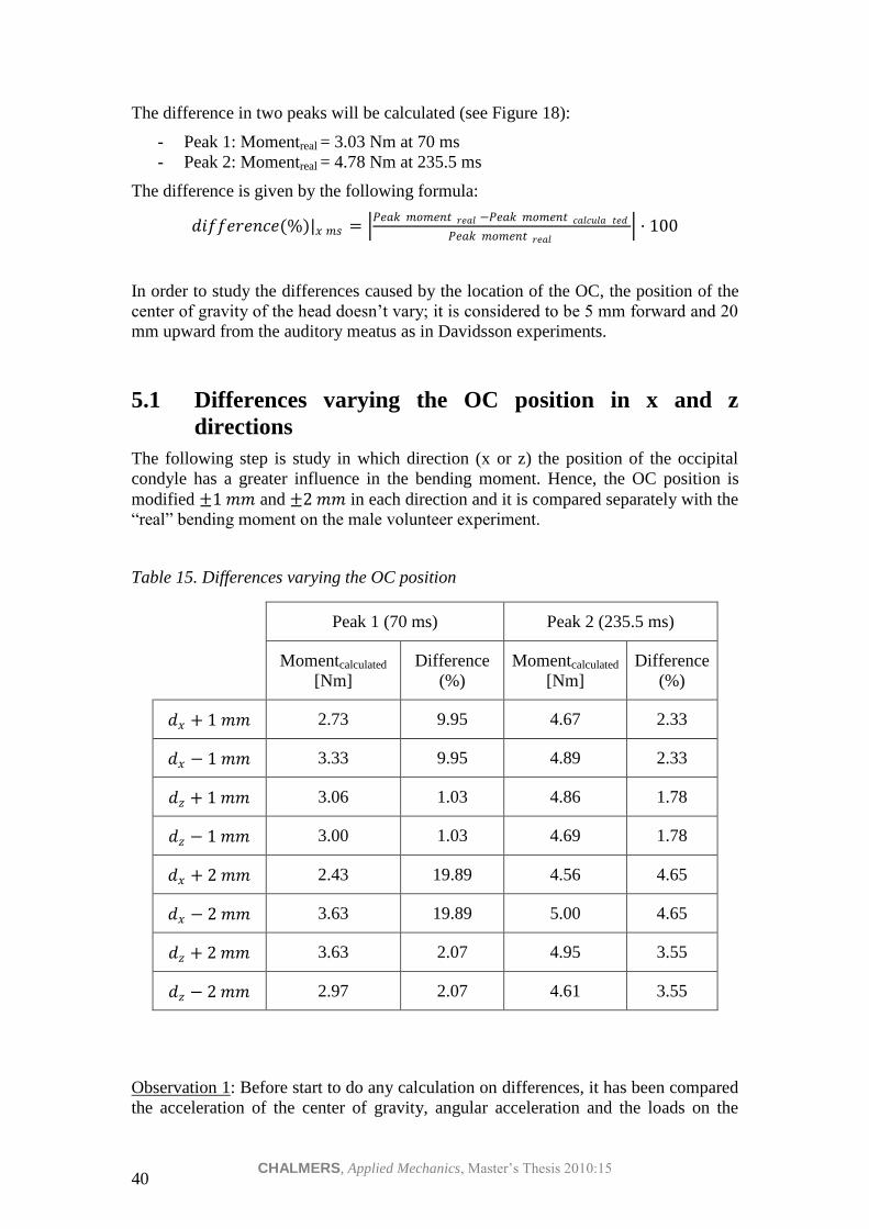
The difference in two peaks will be calculated (see Figure 18):
- Peak 1: Momentreal = 3.03 Nm at 70 ms
- Peak 2: Momentreal = 4.78 Nm at 235.5 ms
The difference is given by the following formula:
𝑑𝑖𝑓𝑓𝑒𝑟𝑒𝑛𝑐𝑒(%)|𝑥 𝑚𝑠 = 𝑃𝑒𝑎𝑘 𝑚𝑜𝑚𝑒𝑛𝑡 𝑟𝑒𝑎𝑙 −𝑃𝑒𝑎𝑘 𝑚𝑜𝑚𝑒𝑛𝑡 𝑐𝑎𝑙𝑐𝑢𝑙𝑎 𝑡𝑒𝑑
𝑃𝑒𝑎𝑘 𝑚𝑜𝑚𝑒𝑛𝑡 𝑟𝑒𝑎𝑙 · 100
In order to study the differences caused by the location of the OC, the position of the
center of gravity of the head doesn’t vary; it is considered to be 5 mm forward and 20
mm upward from the auditory meatus as in Davidsson experiments.
5.1 Differences varying the OC position in x and z
directions
The following step is study in which direction (x or z) the position of the occipital
condyle has a greater influence in the bending moment. Hence, the OC position is
modified ±1 𝑚𝑚 and ±2 𝑚𝑚 in each direction and it is compared separately with the
“real” bending moment on the male volunteer experiment.
Table 15. Differences varying the OC position
Peak 1 (70 ms) Peak 2 (235.5 ms)
Momentcalculated
[Nm]
Difference
(%)
Momentcalculated
[Nm]
Difference
(%)
𝑑𝑥 + 1 𝑚𝑚 2.73 9.95 4.67 2.33
𝑑𝑥 − 1 𝑚𝑚 3.33 9.95 4.89 2.33
𝑑𝑧 + 1 𝑚𝑚 3.06 1.03 4.86 1.78
𝑑𝑧 − 1 𝑚𝑚 3.00 1.03 4.69 1.78
𝑑𝑥 + 2 𝑚𝑚 2.43 19.89 4.56 4.65
𝑑𝑥 − 2 𝑚𝑚 3.63 19.89 5.00 4.65
𝑑𝑧 + 2 𝑚𝑚 3.63 2.07 4.95 3.55
𝑑𝑧 − 2 𝑚𝑚 2.97 2.07 4.61 3.55
Observation 1: Before start to do any calculation on differences, it has been compared
the acceleration of the center of gravity, angular acceleration and the loads on the

CHALMERS, Applied Mechanics, Master’s Thesis 2010:15 41
upper neck with the data given by Davidsson and the data calculated from the 2 uni-
axial accelerometers (see Section 5). Some differences have been found (see
Appendix). Reasons that could explain such fact: the use of a different program to do
all the calculations (perhaps the difference of the decimals used in the calculations),
the inaccuracy of the method use (see Section 2.7), the data used in Section 5 haven’t
been filtered.
Observation 2: Due to observation 2, all the comparisons have been done with respect
to the calculated data, in order to avoid the problem above. From Davidsson’s data, it
only has been used the linear acceleration measured by the upper (U) and lower (L)
accelerometers, the characteristics of the human volunteer and the distances.

CHALMERS, Applied Mechanics, Master’s Thesis 2010:15 42
6 Conclusions
The conclusions of the present research project are:
- The position of the occipital condyles only affects the moment. The upper
neck forces are independent with the location of such point.
- From all the anthropometric studies:
o The head can be considered symmetric midsagittally. It means the
center of gravity of the head is situated on the X-Z plane of the
anatomical coordinate reference.
o Although from the literature related with cadavers it cannot be
extracted any conclusion for the females because there is no specific
data; from the studies with living humans (Young et al. 1983 and
McConville et al. 1980): the average value for the principal moments
of inertia is smaller for females than those obtained on the male
subjects (see Table 13). Hence, it can be concluded that males and
females do not have the same anthropometry, so each gender has its
own values and it cannot mix, otherwise an error, which could be
avoided, is introduced to the results of the calculations.
o Regression equations from Young show a better correlation using 3
measurements of head body sizes than less.
o Comparing regression equations from Beier (19 males + 2 females,
cadavers) and Young (46 living females): Beier’s equations show a
greater correlation than those of Young.
- From Section 5. Errors:
o The location of the occipital condyle has a great influence in the
calculation of the moment in the upper neck.
o In the x-direction the influence is greater than in the z-direction,
comparing relative errors, when OC position is modified.
CHALMERS, Applied Mechanics, Master’s Thesis 2010:15 43
7 Recommendations
- All the devices needed to fix the accelerometers on the head should weigh as
less as possible to avoid modifying the position of the center of gravity of the
volunteer head.
- When using the information gathered from the anthropometric studies, avoid
mixing information from different studies, due to the different ways to
calculate the mass and the moment of inertia of the head.
- The information from the anthropometric studies to calculate the mass and the
moment of inertia of the head should be used only in the humans in whom the
study has focused. For example, if the study is based on females between 35-
45 years old, it shouldn’t be used to calculate the anthropometric
characteristics for a woman who is 22 years old, due to the differences
between them.
- Do not use a head-rest during the experiments. Reason:
o The contact between the head and the head restraint is not a contact
point, although in previous volunteer studies with males (Kroonenberg
et al. 1998) this approximation was used and the position of the contact
point was estimated from the video. But it has one disadvantage, and is
the fact that the head doesn’t have the typical motion in a rear crash,
where the head is stopped by the head-rest.
- Do not use the system with the head strap + mouthpiece to fix the
accelerometers; it has a greater dependence on the distances between the
different points.
- The use of the mouthpiece (Ono et al. 2006) to attach all the sensors is a good
method and also more accurate than the previous method he used (Ono et al.
1996, 1997, 2000), but the inconvenient is that the volunteer has to bite the
mouthpiece and it’s unknown but the tension on his mouth may affect the
muscles on the neck and therefore, the forces and the moments on the upper
neck.
- If the sensors are fixed on the head with a light helmet or another system like
straps, it’s better to fix the sensors in the projection of the center of gravity in
both sides of the head. Hence, the head still keep the symmetry in the
midsagittal plane and the position of the center of gravity of the head doesn’t
change its location. There are no errors due to the distances taken from image
analysis. In that case, the difficulty of the method is to attach the sensors
exactly in the projection of the center of gravity.
If such method is used in the experiment with volunteers:
1) Put the sensors in the projection of the center of gravity in both side of the
human head.
2) Measure linear acceleration (𝑎𝐶𝐺𝑥 , 𝑎𝐶𝐺𝑦 , 𝑎𝐶𝐺𝑧 ), angular acceleration (𝛼),
angular velocity (𝜔𝑥 , 𝜔𝑦 , 𝜔𝑧) and the angle the new sensor IMT40
allows all these measurements.
3) Use equations (1) and (7) to calculate the forces and moments in the upper
neck:
𝐹 = 𝑚 · 𝑎𝐶𝐺
𝑀𝑥 = 𝐼𝑥 · 𝛼𝑥 + 𝐼𝑧 − 𝐼𝑦 · 𝜔𝑦 · 𝜔𝑧

CHALMERS, Applied Mechanics, Master’s Thesis 2010:15 44
𝑀𝑦 = 𝐼𝑦 · 𝛼𝑦 + 𝐼𝑥 − 𝐼𝑧 · 𝜔𝑥 · 𝜔𝑧
𝑀𝑧 = 𝐼𝑧 · 𝛼𝑧 + 𝐼𝑦 − 𝐼𝑥 · 𝜔𝑥 · 𝜔𝑦
CHALMERS, Applied Mechanics, Master’s Thesis 2010:15 45
8 References
Beier G., Schuler E., Schuk M., Ewing C.L., Becker E.D., Thomas D.J. (1980):
Center of gravity and moments of inertia of human heads. Proc. International
IRCOBI Conference of Biomechanics Impacts, 1980, pp. 218-228.
Bierma P. (2009): Whiplash: Symptoms and Treatment. Consumer Health Interactive,
May 28, 2009.
Cappon H., Ratingen M. van, Wismans J., Hell W., Lang D., Svensson M. (2003):
Whiplash Injuries, not Only a Problem in Rear-End Impact. ESV (Enhanced
Safety of Vehicle) Conference, Nagoya, May, Paper 214.
Carlsson A. (2010): Initial Studies of Dynamic Responses of Female and Male
Volunteers in Rear Impact Tests. Ph. D. Thesis. Department of Applied Mechanics,
Chalmers University of Technology, Göteborg, Sweden, 2010, pp. 47.
Chancey V. C., Ottaviano D., Myers B. S., Nightingale R. W. (2006): A kinematic and
anthropometric study of the upper cervical spine and the occipital condyles.
Journal of Biomechanics 40 (2007), pp. 1953-1959.
Chandler R. F., Clauser C. E., McConville J. T., Reynolds H. M., Young J. W. (1975):
Investigation of inertial properties of the human body. AML-TR-74-137, U. S.
Department of Transportation, National Highway Traffic Safety Administration,
Washington D. C., 1975.
Cheng H. B., Yang K. H., Wang Z. G. (2009): Biomechanics of whiplash injury.
Chinese Journal of Traumatology, 2009.
Clauser C. E., McConville J. T., Young J. W. (1969): Weight, volume and center of
mass of segments of the human body. Aerospace Medical Research Laboratory,
Aerospace Medical Division, Air Force Systems Command, Wricht-Patterson Air
Force Base, Ohio, 1969.
Davidsson J. (2000): Development of a Mechanical Model for Rear Impacts:
Evaluation of Volunteer Responses and Validation of the Model. Ph. D. Thesis.
Crash Safety Division, Department of Machine and Vehicle Design, Chalmers
University of Technology, Göteborg, Sweden, 2000, 59pp.
Dempster W. T., Gaughran G. R. L. (1967): Properties of Body Segments Based on
Sized and Weight. The American Journal of Anatomy, Vol. 120, No. 1, January,
1967.
Dumas R., Chèze L., Verriest J. P. (2006): Adjustments to McConville et al. and
Young et al. body segment intertial parmeters. Journal of Biomechanics 40 (2007),
pp. 543-553.
European Transport Safety Council (ETSC) (2007): Reining in whiplash. Better
protection for Europe’s car occupant.
Harrison H. R., Nettleton T. (1997): Advanced engineering dynamics. Electronic
reproduction, Amsterdam, Elsevier Science & Technology, 2007.
Krafft M., Kullgren A., Malm S., Ydenius A. (2005): Influence of Crash Severity on
Various Whiplash Injury Symptoms: a Study Based on Real-Life Rear-End Crashes
with Recorded Crash Pulses. Proc. 19th
Int. Techn. Conf. on ESV, Paper No. 05-
0363.
CHALMERS, Applied Mechanics, Master’s Thesis 2010:15 46
Kroonenberg A. van den, Philippens, M., Cappon, H., Wismans, J., Hell, W.,
Langwieder, K. (1998): Human Head-Neck Response During Low-Speed Rear End
Impacts. Proc. 42nd
Stapp Car Crash Conf., SAE paper 983158, pp. 207-221.
Kullgren A., Eriksson L., Boström O., Krafft M. (2003): Validation of Neck Injury
Criteria Using Reconstructed Real-Life Rear-End Crashes with Recorded Crash
Pulses. Proc. 18th
ESV Conference. Paper No. 344, pp. 1-13.
Ono K., Ejima S., Suzuki Y., Kaneoka K., Fukushima M., Ujihashi S. (2006):
Prediction of Neck Injury Based on the Analysis of Localized Cervical Vertebral
Motion of Human Volunteers During Low-Speed Rear Impacts. Proc. IRCOBI
Conference – Madrid (Spain) – September 2006, pp. 103-113.
Ono K., Kanneoka K., Inami S. (1998): Analysis of Seat Properties on Human
Cervical Vertebral Motion in Low-Speed Rear-End Impacts. In “Frontiers in
Whiplash Trauma”, Yoganandan N., Publisher IOS Press, Amsterdam, The
Netherlands, 2000, pp. 372-388.
Ono K., Kaneoka K., Wittek A., Kajzer J. (1997): Cervical Injury Mechanism Based
on the Analysis of Human Cervical Vertebral Motion and Head-Neck-Torso
Kinematics During Low Speed Rear Impacts. Proc. 41st Stapp Car Crash Conf., pp
339-356.
Ono K., Kanno M. (1996): Influences of the Physical Parameters on the Risk to Neck
Injuries in Low Impact Speed Rear-end Collisions. Accident Analysis and
Prevention, Vol. 28, No.4, 1996, pp. 493-499.
McConville J. T., Churchili T. D., Kaleps I, Clauser C. E. (1980): Anthropometric
Relationships of Body and Body Segment Moments of Inertia. AMRL-TR-71-88,
Aerospace Medical Research Laboratory, Aerospace Medical Division, Air Force
Systems Command, Wrigth Patterson Air Force Base, Ohio.
Mertz H.J., Patrick L.M. (1967): Investigation of the Kinematics and Kinetics of
Whiplash. Proc. 11th
Stapp Car Crash Conf., SAE paper 670919, pp. 267-317.
Mertz H.J., Patrick L.M. (1971): Strength and Response of the Human Neck. Proc.
15th
Stapp Car Crash Conf., SAE paper 710855, pp 207-255.
Panjabi M. M., Cholewicki J., Nibu K., Grauer J. N., Babat L. B., Dvorak J. (1998):
Mechanism of whiplash injury. Clinical Biomechanics, Vol. 13, Issues 4-5, June-
July 1998, pp 239-249.
Plaga J. A., Albery C., Boehmer M., Goodyear C., Thomas G. (2005): Design and
Development of Anthropometrically Correct Head Forms for Joint Strike Fighter
Ejection Seat Testing. AFRL-HE-WP-TR-2005-0044, Human Effectiveness
Directorate Biosciences and Protection Division Biomechanics Branch, Wright-
Patterson, 2005.
Robbins D. H. (1983): Anthropometric Specifications for Mid-Sized Male Dummy,
Volume 2 / Anthropometric Specifications for Small Female & Large Male
Dummies, Volume 3. UMTRI-83-53-2, U. S. Department of Transportation,
National Highway Traffic Safety Administration, Washington D. C., 1983.
Schneider L. W., Robbins D. H., Pflüg M. A., Snyder R. G. (1983): Development of
anthropometrically based design specifications for an advanced adult
anthropomorphic dummy family, volume 1. UMTRI-83-53-1, U. S. Department of
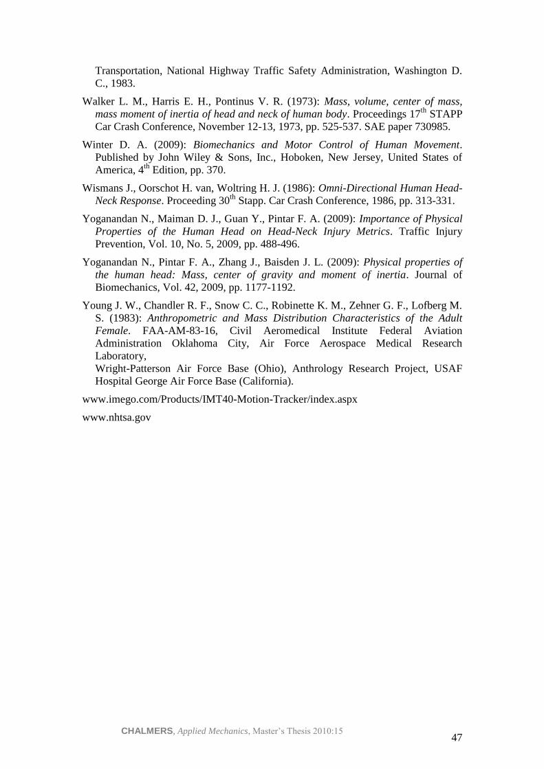
CHALMERS, Applied Mechanics, Master’s Thesis 2010:15 47
Transportation, National Highway Traffic Safety Administration, Washington D.
C., 1983.
Walker L. M., Harris E. H., Pontinus V. R. (1973): Mass, volume, center of mass,
mass moment of inertia of head and neck of human body. Proceedings 17th
STAPP
Car Crash Conference, November 12-13, 1973, pp. 525-537. SAE paper 730985.
Winter D. A. (2009): Biomechanics and Motor Control of Human Movement.
Published by John Wiley & Sons, Inc., Hoboken, New Jersey, United States of
America, 4th
Edition, pp. 370.
Wismans J., Oorschot H. van, Woltring H. J. (1986): Omni-Directional Human Head-
Neck Response. Proceeding 30th
Stapp. Car Crash Conference, 1986, pp. 313-331.
Yoganandan N., Maiman D. J., Guan Y., Pintar F. A. (2009): Importance of Physical
Properties of the Human Head on Head-Neck Injury Metrics. Traffic Injury
Prevention, Vol. 10, No. 5, 2009, pp. 488-496.
Yoganandan N., Pintar F. A., Zhang J., Baisden J. L. (2009): Physical properties of
the human head: Mass, center of gravity and moment of inertia. Journal of
Biomechanics, Vol. 42, 2009, pp. 1177-1192.
Young J. W., Chandler R. F., Snow C. C., Robinette K. M., Zehner G. F., Lofberg M.
S. (1983): Anthropometric and Mass Distribution Characteristics of the Adult
Female. FAA-AM-83-16, Civil Aeromedical Institute Federal Aviation
Administration Oklahoma City, Air Force Aerospace Medical Research
Laboratory,
Wright-Patterson Air Force Base (Ohio), Anthrology Research Project, USAF
Hospital George Air Force Base (California).
www.imego.com/Products/IMT40-Motion-Tracker/index.aspx
www.nhtsa.gov
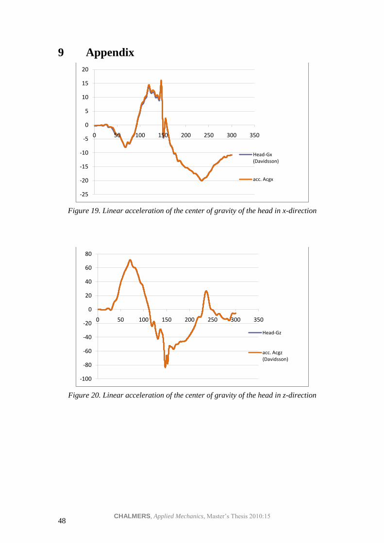
CHALMERS, Applied Mechanics, Master’s Thesis 2010:15 48
9 Appendix
Figure 19. Linear acceleration of the center of gravity of the head in x-direction
Figure 20. Linear acceleration of the center of gravity of the head in z-direction
-25
-20
-15
-10
-5
0
5
10
15
20
0 50 100 150 200 250 300 350
Head-Gx (Davidsson)
acc. Acgx
-100
-80
-60
-40
-20
0
20
40
60
80
0 50 100 150 200 250 300 350
Head-Gz
acc. Acgz (Davidsson)

CHALMERS, Applied Mechanics, Master’s Thesis 2010:15 49
Figure 21. Angular acceleration of the head
Figure 22. Upper neck force in the x-direction
-300
-200
-100
0
100
200
300
0 100 200 300 400
Angular acc.
Head-Ang,Acc (Davidsson)
-120
-100
-80
-60
-40
-20
0
20
40
60
80
0 50 100 150 200 250 300 350
Neck-Fx (Davidsson)
Fx
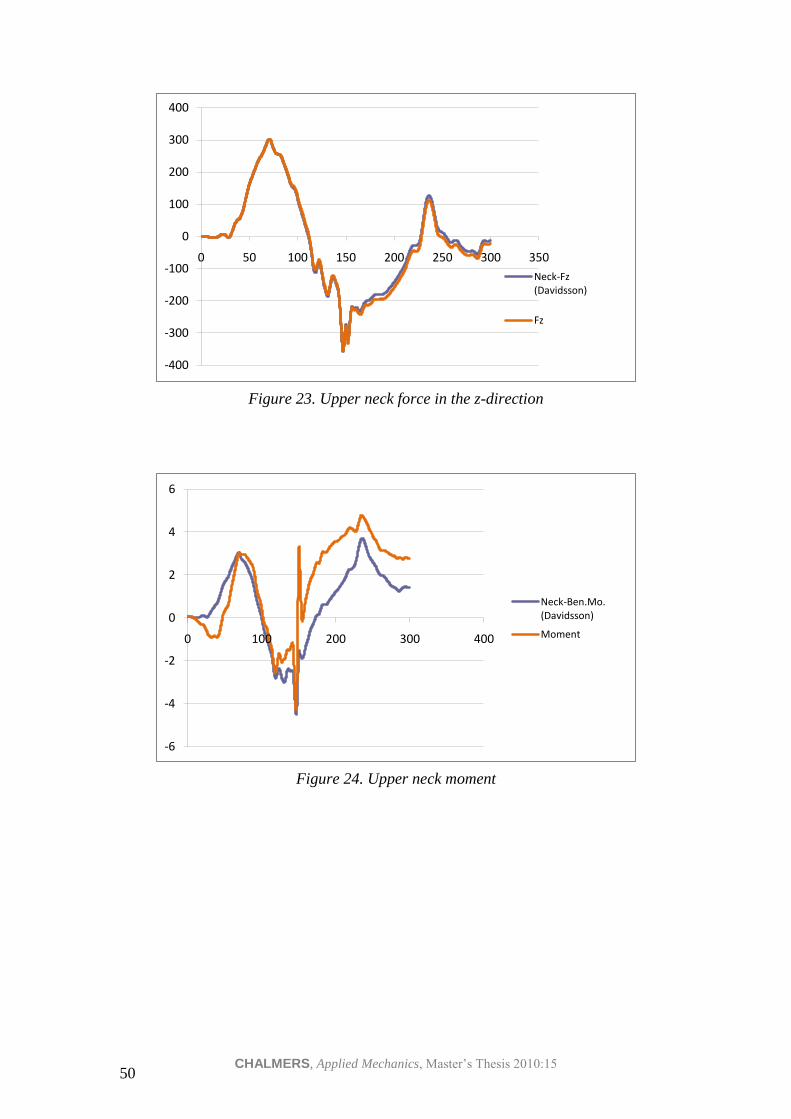
CHALMERS, Applied Mechanics, Master’s Thesis 2010:15 50
Figure 23. Upper neck force in the z-direction
Figure 24. Upper neck moment
-400
-300
-200
-100
0
100
200
300
400
0 50 100 150 200 250 300 350
Neck-Fz (Davidsson)
Fz
-6
-4
-2
0
2
4
6
0 100 200 300 400
Neck-Ben.Mo. (Davidsson)
Moment

CHALMERS, Applied Mechanics, Master’s Thesis 2010:15 51