TEST METHOD STANDARD ELECTRONIC AND ELECTRICAL COMPONENT PARTS
191
MIL-STD-202G 8 February 2002 SUPERSEDING MIL-STD-202F 1 APRIL 1980 DEPARTMENT OF DEFENSE TEST METHOD STANDARD ELECTRONIC AND ELECTRICAL COMPONENT PARTS AMSC N/A FSC 59GP DISTRIBUTION STATEMENT A. Approved for public release; distribution is unlimited. INCH-POUND The documentation and process conversion measures necessary to comply with this revision shall be completed by 8 July 2002.
-
Upload
giuseppe-gori -
Category
Documents
-
view
229 -
download
0
Transcript of TEST METHOD STANDARD ELECTRONIC AND ELECTRICAL COMPONENT PARTS
7/29/2019 TEST METHOD STANDARD ELECTRONIC AND ELECTRICAL COMPONENT PARTS
http://slidepdf.com/reader/full/test-method-standard-electronic-and-electrical-component-parts 1/191
MIL-STD-202G8 February 2002SUPERSEDINGMIL-STD-202F1 APRIL 1980
DEPARTMENT OF DEFENSE TEST METHOD STANDARD
ELECTRONIC AND ELECTRICAL COMPONENT PARTS
AMSC N/A FSC 59GPDISTRIBUTION STATEMENT A. Approved for public release; distribution is unlimited.
INCH-POUND
The documentation and process conversionmeasures necessary to comply with thisrevision shall be completed by 8 July 2002.

7/29/2019 TEST METHOD STANDARD ELECTRONIC AND ELECTRICAL COMPONENT PARTS
http://slidepdf.com/reader/full/test-method-standard-electronic-and-electrical-component-parts 2/191
MIL-STD-202G
FOREWORD
1. This military standard is approved for use by all Departments and Agencies of the Department of Defense.
2. Beneficial comments (recommendations, additions, deletions) and any pertinent data which may be of use inimproving this document should be addressed to: Defense Supply Center Columbus, P.O.Box 3990, Columbus,OH 43216-5000, by using the self-addressed Standardization Document Improvement Proposal (DDForm 1426)appearing at the end of this document or by letter.
ii

7/29/2019 TEST METHOD STANDARD ELECTRONIC AND ELECTRICAL COMPONENT PARTS
http://slidepdf.com/reader/full/test-method-standard-electronic-and-electrical-component-parts 3/191
MIL-STD-202G
CONTENTS
PARAGRAPH Page
1. SCOPE………………………………………………………………………………………. 11.1 Purpose…………………………………………………………………………………… 11.2 Test method numbering system……………………………………………………….. 11.3 Method of reference……………………………………………………………………… 1
2. APPLICABLE DOCUMENTS……………………………………………………………… 22.1 General…………………………………………………………………………………… 22.2 Government documents………………………………………………………………… 22.3 Non-Government publications…………………………………………………………. 32.4 Order of precedence…………………………………………………………………….. 3
3. DEFINITIONS……………………………………………………………………………….. 3
4. GENERAL REQUIREMENTS……………………………………………………………… 44.1 Test requirements……………………………………………………………………….. 4
4.2 Test conditions…………………………………………………………………………… 44.3 Reference conditions……………………………………………………………………. 44.4 Calibration requirements………………………………………………………………… 4
5. DETAILED REQUIREMENTS…………………………………………………………….. 4
6. NOTES………………………………………………………………………………………. 46.1 Intended use……………………………………………………………………………… 46.2 Sequence of tests……………………………………………………………………….. 56.3 Chemical listing………………………………………………………………………….. 56.4 Subject term (key word) listing…………………………………………………………. 6
NUMERICAL INDEX OF TEST METHODS……………………………………………… 7
iii

7/29/2019 TEST METHOD STANDARD ELECTRONIC AND ELECTRICAL COMPONENT PARTS
http://slidepdf.com/reader/full/test-method-standard-electronic-and-electrical-component-parts 4/191
7/29/2019 TEST METHOD STANDARD ELECTRONIC AND ELECTRICAL COMPONENT PARTS
http://slidepdf.com/reader/full/test-method-standard-electronic-and-electrical-component-parts 5/191
MIL-STD-202G
1. SCOPE
1.1 Purpose. This standard establishes uniform methods for testing electronic and electrical component parts,
including basic environmental tests to determine resistance to deleterious effects of natural elements and conditionssurrounding military operations, and physical and electrical tests. For the purpose of this standard, the term"component parts" includes such items as capacitors, resistors, switches, relays, transformers, inductors, and others.This standard is intended to apply only to small component parts, weighing up to 300 pounds or having a root meansquare test voltage up to 50,000 volts unless otherwise specifically invoked. The test methods described herein havebeen prepared to serve several purposes:
a. To specify suitable conditions obtainable in the laboratory that give test results equivalent to the actualservice conditions existing in the field, and to obtain reproducibility of the results of tests. The testsdescribed herein are not to be interpreted as an exact and conclusive representation of actual serviceoperation in any one geographic location, since the only true test for operation in a specific location is anactual service test at that point.
b. To describe in one standard (1) all of the test methods of a similar character which appeared in the various joint or single-service electronic and electrical component parts specifications, (2) those test methods which
are feasible for use in several specifications, and (3), the recognized extreme environments, particularlytemperatures, barometric pressures, etc., at which component parts will be tested under some of thepresently standardized testing procedures. By so consolidating, these methods may be kept uniform andthus result in conservation of equipment, man-hours, and testing facilities. In achieving these objectives, it isnecessary to make each of the general tests adaptable to a broad range of electronic and electricalcomponent parts.
c. The test methods described herein for environmental, physical, and electrical tests shall also apply, whenapplicable, to parts not covered by an approved military specification, military sheet form standard,specification sheet, or drawing.
1.2 Test method numbering system. The test methods are designated by numbers assigned in accordance withthe following system:
1.2.1 Class of tests. The tests are divided into three classes: Test methods numbered 101 to 199 inclusive, cover
environmental tests; those numbered 201 to 299 inclusive, cover physical characteristics tests; and those numbered301 to 399 inclusive, cover electrical characteristics tests. Within each class, test methods are serially numbered inthe order in which they are introduced into this standard.
1.2.2 Revision of test methods. Revisions of test methods are indicated by a letter following the method number.For example, the original number assigned to the moisture resistance test method is 106; the first revision of thatmethod is 106A, the second revision, 106B, etc.
1.3 Method of reference. When applicable, test methods contained herein shall be referenced in the individualspecification by specifying this standard, the method number, and the details required in the summary paragraph ofthe referenced method. To avoid the necessity for changing specifications which refer to this standard, the revisionletter following the method number shall not be used when referencing test methods. For example, use “Method106”, not “Method 106A”.
1 of 7
7/29/2019 TEST METHOD STANDARD ELECTRONIC AND ELECTRICAL COMPONENT PARTS
http://slidepdf.com/reader/full/test-method-standard-electronic-and-electrical-component-parts 6/191
MIL-STD-202G
2. APPLICABLE DOCUMENTS
2.1 General. The documents listed in this section are specified in sections 3, 4, 5, and individual test methods of
this standard. This section does not include documents cited in other sections of this standard or recommended foradditional information or as examples. While every effort has been made to ensure the completeness of this list,document users are cautioned that they must meet all specified requirements documents cited in sections 3, 4, 5, andthe individual test methods, whether or not they are listed.
2.2 Government documents.
2.2.1 Specifications, standards, and handbooks. The following specifications, standards, and handbooks form apart of this document to the extent specified herein. Unless otherwise specified, the issues of these documents arethose listed in the issue of the Department of Defense Index of Specifications and Standards (DODISS) andsupplement thereto, cited in the solicitation.
SPECIFICATIONS
DEPARTMENT OF DEFENSE
MIL-PRF-680 - Degreasing Solvent
MIL-S-901 - Shock Tests, HI (High Impact), Shipboard Machinery, Equipment and Systems,Requirements For
MIL-DTL-1222 - Studs, Bolts, Hex Cap Screws, Socket Head Cap Screws and Nuts
MIL-I-24768/14 - Insulation, Plastic, Laminated, Thermosetting, Cotton-Fabric-Base, Phenolic-Resin (FBG)
FEDERAL
QQ-B-654 - Brazing Alloys, Silver
QQ-S-698 - Steel, Sheet and Strip, Low Carbon
TT-I-735 - Isopropyl Alcohol
2.2.2 Other government documents, drawings, and publications. The following other government documents,drawings, and publications form a part of this document to the extent specified herein. Unless otherwise specified,the issues are those cited in the solicitation.
CODE OF FEDERAL REGULATIONS (CFR)
10 CFR 20 - Standards For Protection Against Radiation10 CFR 30 - Rules of General Applicability to Domestic Licensing of Byproduct Material
10 CFR 31 - General Domestic Licenses For Byproduct Material
10 CFR 32 - Specific Domestic Licenses to Manufacture or Transfer Certain Items ContainingByproduct Material
2
7/29/2019 TEST METHOD STANDARD ELECTRONIC AND ELECTRICAL COMPONENT PARTS
http://slidepdf.com/reader/full/test-method-standard-electronic-and-electrical-component-parts 7/191
MIL-STD-202G
2.3 Non-Government publications. The following document(s) form a part of this document to the extent specifiedherein. Unless otherwise specified, the issues of the document(s) that are DoD adopted are those listed in the issueof the DoDISS cited in the solicitation. Unless otherwise specified, the issues of documents not listed in the DoDISS
are the issues of the documents cited in the solicitation (see 6.2).
ACOUSTICAL SOCIETY OF AMERICA
ASA 2.2-1959 - Methods for the Calibration of Shock and Vibration Pickups
(Application for copies should be addressed to Acoustical Society of America, 120 Wall Street, 32nd
Floor, NewYork, NY 10005-3993.)
AMERICAN NATIONAL STANDARDS INSTITUTE (ANSI)
ANSI/NCSL Z540-1 - Calibration Laboratories and Measuring and Test Equipment, GeneralRequirements
ANSI/J-STD-002 - Solderability Tests For Component Leads, Terminations, Lugs, Terminals and
Wires
ANSI/J-STD-004 - Requirements For Soldering Fluxes
ANSI/J-STD-005 - Requirements For Soldering Pastes
ANSI/J-STD-006 - Requirements For Electronic Grade Solder Alloys and Fluxed and Non-Fluxed SolidSolders For Electronic Soldering Applications
(Application for copies should be addressed to the American National Standards Institute, Incorporated, 1430Broadway, New York, NY 10018.)
AMERICAN SOCIETY FOR TESTING AND MATERIALS
ASTM A-519-96 - Standard Specification For Seamless Carbon and Alloy Steel Mechanical Tubing
(Application for copies should be addressed to the American National Standards Institute, Incorporated, 1430Broadway, New York, NY 10018.)
INSTITUTE FOR INTERCONNECTING AND PACKAGING ELECTRONIC CIRCUITS
IPC-4101 - Specification For Base Materials For Rigid and Multilayer Printed Boards
(Application for copies should be addressed to the Institute for Interconnecting and Packaging Electronic Circuits,2215 Sanders Road, Northbrook, IL 60062-6131.)
(Non-Government standards and other publications are normally available from the organizations that prepare ordistribute the documents. These documents also may be available in or through libraries or other informationalservices.)
2.4 Order of precedence. In the event of a conflict between the text of this document and the references citedherein, the text of this document takes precedence. Nothing in this document, however, supersedes applicable lawsand regulations unless a specific exemption has been obtained.
3. DEFINITIONS
This section is not applicable to this standard.
3
7/29/2019 TEST METHOD STANDARD ELECTRONIC AND ELECTRICAL COMPONENT PARTS
http://slidepdf.com/reader/full/test-method-standard-electronic-and-electrical-component-parts 8/191
MIL-STD-202G
4. GENERAL REQUIREMENTS
4.1 Test requirements. The requirements which must be met by the component parts subjected to the test
methods described herein are specified in the individual specifications. Whenever this standard conflicts with theindividual specification, the latter shall govern.
4.2 Test conditions. Unless otherwise specified herein, or in the individual specification, all measurements and
tests shall be made at temperatures of 15°C to 35°C (59°F to 95°F) and at ambient air pressure and relative humidity.Whenever these conditions must be closely controlled in order to obtain reproducible results, for referee purposes, a
temperature of 25°C, +0°C, -2°C (77°F, +0°F, -3.6°F), relative humidity of 50 ±2 percent, and atmospheric pressure of650 to 800 millimeters of mercury shall be specified.
4.2.1 Permissible temperature variation in environmental chambers. When chambers are used, specimens undertest shall be located only within the working area defined as follows:
a. Temperature variation within working area: The controls for the chamber shall be capable of maintaining the
temperature of any single reference point within the working area within ±2°C (3.6°F).
b. Space variation within working area: Chambers shall be so constructed that, at any given time, thetemperature of any point within the working area shall not deviate more than 3°C (5.4°F) from the referencepoint except for the immediate vicinity of specimens generating heat.
4.3 Reference conditions. Reference conditions as a base for calculations shall be 25°C (77°F) for temperature, or
an alternate temperature of 20°C (68°F), 760 millimeters of mercury for air pressure, and a relative humidity of 50percent.
4.4 Calibration requirements. Calibration shall be applied to those items of measuring and test equipment used toassure product compliance with specifications and contractual requirements. Calibration shall be performed inaccordance with the requirements of ANSI/NCSL Z540-1 or equivalent. Calibrated items shall be controlled, used,and stored in a manner suitable to protect calibration integrity. Test equipment requiring calibration shall be identifiedand labeled in accordance with ANSI/NCSL Z540-1 or equivalent.
5. DETAILED REQUIREMENTS
This section is not applicable to this standard.
6. NOTES
(This section contains information of a general or explanatory nature which may be helpful, but is not mandatory).
6.1 Intended use. This test method standard specifies uniform procedures for the environmental, physical, andelectrical testing of electronic and electrical component piece parts. It is intended as a reference document for testrequirements called out in military component specifications and when specified, in other procurementspecifications and drawings.
4

7/29/2019 TEST METHOD STANDARD ELECTRONIC AND ELECTRICAL COMPONENT PARTS
http://slidepdf.com/reader/full/test-method-standard-electronic-and-electrical-component-parts 9/191
MIL-STD-202G
6.2 Sequence of tests. The sequence of tests that follow is provided for guidance to specification writers toemphasize the philosophy that parts be mechanically and thermally stressed prior to being subjected to a moistureresistance test. Within any of the three groups and subgroups, the order is preferred but not mandatory. It is
recommended that this sequence be followed in all new specifications and when feasible, in revisions of existingspecifications. In the case of hermetically sealed parts, when a moisture resistance test is not required, a highsensitivity seal test may be used in lieu of the moisture resistance test.
Group I (all samples) Group lla (part of a sample) Group llb (part of a sample)Visual inspection Shock Resistance to soldering heatMechanical inspection Acceleration Terminal StrengthElectrical measurements Vibration Thermal ShockHermetic seal test (if applicable)
Group III (all units which have passed group II tests)Moisture resistance or seal test on hermetically sealed parts
6.3 Chemical listing. The following is a list of chemicals and their chemical abstracts service (CAS) registrynumber identified for use in MIL-STD-202 test methods:
Material CAS number Test method
ethylbenzene 100-41-4 215fluorocarbon/perfluorocarbon ----------- 107, 112, 210helium 7440-59-7 112hydrochloric acid 47-01-0 101isopropyl alcohol 67-63-0 215kerosene 8008-20-6 215krypton-85 13983-27-2 112mineral oil 8012-95-1 112mineral spirits 8052-41-3 215monoethanolamine 141-43-5 215n-hexane 110-54-3 109peanut oil 8002-03-7 112
propane 74-98-6 111propylene glycol monomethylether 107-98-2 215silicone oil 63148-58-3 112sodium chloride 7647-14-5 104sodium hydroxide 1310-73-2 101terpene ------------ 215
5

7/29/2019 TEST METHOD STANDARD ELECTRONIC AND ELECTRICAL COMPONENT PARTS
http://slidepdf.com/reader/full/test-method-standard-electronic-and-electrical-component-parts 10/191
MIL-STD-202G
6.4 Subject term (key word) listing.
Acceleration
Barometric pressureCapacitanceContact chatter/resistanceCurrent noiseCurrent switchingDC resistanceDielectric withstanding voltageExplosionFlammabilityHumidityImmersionInsulation resistanceLifeMoisture resistancePIND
Quality factorRadiographic inspectionRandom dropResistance-temperature characteristicResistance to soldering heatResistance to solventsSalt atmosphereSand and dustShockSolderabilityTerminal strengthThermal shockVibrationVoltage coefficient
6.5 Changes from previous issue. Marginal notations are not used in this revision to identify changes with respectto the previous issue due to the extent of the changes.
Custodians: Preparing activity:Army - CR DLA – CCNavy - ECAir Force - 11 (Project 59GP-0170)
Review activities:Army - AR, AT, AV, CR4, MI, SM, TENavy - AS, OS, SHAir Force - 19, 99NSA - NS
6

7/29/2019 TEST METHOD STANDARD ELECTRONIC AND ELECTRICAL COMPONENT PARTS
http://slidepdf.com/reader/full/test-method-standard-electronic-and-electrical-component-parts 11/191
MIL-STD-202G
NUMERICAL INDEX OF TEST METHODS
Test MethodNumber Date Title
Environmental tests (100 class)
101E102A103B104A105C106G107G108A109C110A
111A112E
8 February 2002Cancelled12 September 196324 October 195612 September 1963
8 February 200228 March 198412 September 1963
8 February 200216 April 1973
16 April 197311 October 1988
Salt atmosphere (corrosion) (formerly called salt spray)Superseded by Method 107 (see note on Method 102)Humidity (steady state)ImmersionBarometric pressure (reduced)Moisture resistanceThermal shockLife (at elevated ambient temperature)ExplosionSand and dust
Flammability (external flame)Seal
Physical characteristics tests (200 class)
201A202D203C204D205E206207B208H209210F211A212A213B214A215K216217A
24 October 1956Cancelled
8 February 20021 April 1980
Cancelled12 September 1963
8 February 200231 January 199618 May 1962
8 February 200214 April 196916 April 197316 April 197328 March 1984
8 February 2002Cancelled
8 February 2002
VibrationSuperseded by Method 213 (see note on Method 202)Random dropVibration, high frequencySuperseded by Method 213 (see note on Method 205)Life (rotational)High-impact shockSolderabilityRadiographic inspectionResistance to soldering heatTerminal strengthAccelerationShock (specified pulse)Random vibrationResistance to solventsSuperseded by Method 210 (see note on Method 216)Particle impact noise detection (PIND)
Electrical characteristics tests (300 class)
301302303
304305306307308309310311312
6 February 19566 February 19566 February 1956
24 October 195624 October 195624 October 195624 October 195629 November 196127 May 196520 January 196714 April 196916 April 1973
Dielectric withstanding voltageInsulation resistanceDC resistance
Resistance temperature characteristicCapacitanceQuality factor (Q)Contact resistanceCurrent-noise test for fixed resistorsVoltage coefficient of resistance determination procedureContact-chatter monitoringLife, low level switchingIntermediate current switching
7

7/29/2019 TEST METHOD STANDARD ELECTRONIC AND ELECTRICAL COMPONENT PARTS
http://slidepdf.com/reader/full/test-method-standard-electronic-and-electrical-component-parts 12/191

7/29/2019 TEST METHOD STANDARD ELECTRONIC AND ELECTRICAL COMPONENT PARTS
http://slidepdf.com/reader/full/test-method-standard-electronic-and-electrical-component-parts 13/191
MIL-STD-202G
CLASS 100
ENVIRONMENTAL TESTS

7/29/2019 TEST METHOD STANDARD ELECTRONIC AND ELECTRICAL COMPONENT PARTS
http://slidepdf.com/reader/full/test-method-standard-electronic-and-electrical-component-parts 14/191

7/29/2019 TEST METHOD STANDARD ELECTRONIC AND ELECTRICAL COMPONENT PARTS
http://slidepdf.com/reader/full/test-method-standard-electronic-and-electrical-component-parts 15/191
MIL-STD-202G
METHOD 101E
SALT ATMOSPHERE (CORROSION)(formerly Salt Spray (Corrosion))
1. PURPOSE. The salt-spray test, in which specimens are subjected to a fine mist of salt solution, has several
useful purposes when utilized with full recognition of its deficiencies and limitations. Originally proposed as anaccelerated laboratory corrosion test simulating the effects of seacoast atmospheres on metals, with or withoutprotective coatings, this test has been erroneously considered by many as an all-purpose accelerated corrosion test,which if "withstood successfully" will guarantee that metals or protective coatings will prove satisfactory under anycorrosive condition. Experience has since shown that there is seldom a direct relationship between resistance to saltatmosphere corrosion and resistance to corrosion in other media, even in so-called "marine" atmospheres andseawater. However, some idea of the relative service life and behavior of different samples of the same (or closelyrelated) metals or of protective coating-base metal combinations in marine and exposed seacoast locations can begained by means of the salt atmosphere test, provided accumulated data from correlated field service tests andlaboratory salt atmosphere tests show that such a relationship does exist, as in the case of aluminum alloys. (Suchcorrelation tests are also necessary to show the degree of acceleration, if any, produced by the laboratory test). Thesalt atmosphere test is generally considered unreliable for comparing the general corrosion resistance of differentkinds of metals or coating-metal combinations, or for predicting their comparative service life. The salt atmospheretest has received its widest acceptance as a test for evaluating the uniformity (specifically, thickness and degree ofporosity) of protective coatings, metallic and nonmetallic, and has served this purpose with varying amounts of
success. In this connection, the test is useful for evaluating different lots of the same product, once some standardlevel of performance has been established. The salt atmosphere test is especially helpful as a screening test forrevealing particularly inferior coatings. When used to check the porosity of metallic coatings, the test is moredependable when applied to coatings that are cathodic rather than anodic toward the basic metal. This test can alsobe used to detect the presence of free iron contaminating the surface of another metal, by inspection of the corrosionproducts.
2. APPARATUS. Apparatus used in the salt atmosphere test shall include the following:
a. Exposure chamber with racks or fixtures for supporting specimens.
b. Salt-solution reservoir with means for monitoring an adequate level of solution.
c. Means for atomizing the salt solution, including suitable nozzles and compressed air supply.
d. Chamber-heating means and controls.
e. Means for humidifying the air at a temperature above the chamber temperature.
2.1 Chamber. The chamber and all accessories shall be made of material that will not affect the corrosiveness ofthe salt atmosphere, such as glass, hard rubber, or plastic. All parts of the test setup that come in contact with testspecimens shall be of materials that will not cause electrolytic corrosion. The chamber and accessories shall be soconstructed and arranged that there is no direct impinging of the spray or dripping of the condensate on thespecimens, so that the atmosphere circulates freely about all specimens to the same degree, and so that no liquidwhich has come in contact with the test specimens returns to the salt-solution reservoir. The chamber shall beproperly vented to prevent pressure build up and allow uniform distribution of salt spray. The chamber shall have asuitable means of heating and maintaining the required test temperature.
2.2 Salt solution reservoir. The salt solution reservoir shall be made of material that is non-reactive with the salt
solution, e.g., glass, hard rubber, or plastic. The reservoir shall be adequately protected from the surroundingenvironment and shall have a means to monitor the solution level. The reservoir shall include a means to filter thesalt solution in the supply line to the atomizers. When long duration test conditions are specified (e.g. test conditionD), the reservoir may be refilled via auxiliary reservoirs so that the test cycle shall not be interrupted.
METHOD 101E 8 February 2002
1 of 4

7/29/2019 TEST METHOD STANDARD ELECTRONIC AND ELECTRICAL COMPONENT PARTS
http://slidepdf.com/reader/full/test-method-standard-electronic-and-electrical-component-parts 16/191
MIL-STD-202G
2.3 Air supply. The compressed air entering the atomizers shall be free from all impurities such as oil and dirt.Means shall be provided to humidify and warm the compressed air as required to meet the operating conditions. Theair pressure shall be suitable to produce a finely divided dense fog with the atomizer(s) used. To insure againstclogging the atomizers by salt deposition, the air should have a relative humidity of 95 to 98 percent at the point ofrelease from the nozzle. A satisfactory method is to pass the air in very fine bubbles through a tower containing
heated water. The temperature of the water should be 95°F (35°C) or higher. The permissible temperatureincreases with increasing volume of air and with decreasing heat insulation of the chamber and temperature of itssurroundings. It should not exceed a value above which an excess of moisture is introduced into the chamber (e.g.
110°F (43.3°C) at an air pressure of 12 pounds psi), or a value that makes it impossible to meet the requirement foroperating temperature.
3. SALT SOLUTION. The salt used shall be sodium chloride (NaCl) containing on the dry basis not more than 0.1percent of sodium iodide, and not more than 0.5 percent of total impurities. Do not use sodium chloride (NaCl)containing anti-caking agents because such agents may act as corrosion inhibitors. Unless otherwise specified, the
salt solution concentration shall be 5 ±1 percent. The 5 percent solution shall be prepared by dissolving 5 ±1 parts byweight of salt in 95 parts by weight of distilled or deionized water. Water used in the preparation of solutions shallcontain not more than 200 parts per million of total solids. The salt solution shall be kept free from solids by filtration.The solution shall be adjusted to and maintained at a specific gravity in accordance with figure 101-1. The pH shall
be maintained between 6.5 and 7.2 when measured at a temperature of 95°F ±5°F (35°C ±3°C). Only dilute cp gradehydrochloric acid or sodium hydroxide shall be used to adjust the pH.
4. PREPARATION OF SPECIMENS. Specimens shall be given a minimum of handling, particularly on thesignificant surfaces, and shall be prepared for test immediately before exposure. Unless otherwise specified,uncoated metallic or metallic-coated specimens shall be thoroughly cleaned of oil, dirt, and grease as necessary untilthe surface is free from water break. The cleaning methods shall not include the use of corrosive solvents norsolvents which deposit either corrosive or protective films, nor the use of abrasives other than a paste of puremagnesium oxide. Specimens having an organic coating shall not be solvent cleaned. Those portions of specimenswhich come in contact with the support and, unless otherwise specified in the case of coated specimens or samples,cut edges and surfaces not required to be coated, shall be protected with a suitable coating of wax or similarsubstance impervious to moisture.
5. PROCEDURE.
5.1 Maintenance and conditioning of test chamber. The chamber shall be cleaned each time the salt solution in
the reservoir has been used up to assure that all materials that could adversely affect the results of subsequent testsare removed. However, no test shall be interrupted for the purpose of chamber cleaning. After the cleaning cycle,upon restarting the chamber, the reservoir shall be filled with salt solution and the chamber shall be stabilized byoperating it until the temperature comes to equilibrium, see 5.3. Intermittent operation of the chamber is acceptable,provided the pH and concentration of the salt solution are kept within limits, see 3.
5.2 Location of specimens. Unless otherwise specified, flat specimens and, where practicable, other specimensshall be supported in such a position that the significant surface is approximately 15 degrees from the vertical andparallel to the principal direction of horizontal flow of the fog through the chamber. Other specimens shall bepositioned so as to insure most uniform exposure. Whenever practicable, the specimens shall be supported from thebottom or from the side. When specimens are suspended from the top, suspension shall be by means of glass orplastic hooks or wax string; if plastic hooks are used, they shall be fabricated of material that is non-reactive to thesalt solution such as lucite. The use of metal hooks is not permitted. Specimens shall be positioned so that they donot contact each other, so that they do not shield each other from the freely settling fog, and so that corrosionproducts and condensate from one specimen do not fall upon another.
METHOD 101E8 February 2002
2

7/29/2019 TEST METHOD STANDARD ELECTRONIC AND ELECTRICAL COMPONENT PARTS
http://slidepdf.com/reader/full/test-method-standard-electronic-and-electrical-component-parts 17/191
MIL-STD-202G
5.3 Chamber operation. A salt fog having a temperature of 95°F minimum (35°C minimum) shall be passedthrough the chamber for the specified test duration (see 5.4). The exposure zone of the chamber shall be maintained
at a temperature of 95°F ±5°F (35°C ±3°C). The conditions maintained in all parts of the exposure zone shall besuch that a suitable receptacle placed at any point in the exposure zone will collect from 0.5 to 3.0 milliliters ofsolution per hour for each 80 square centimeters (0.5-3ml/hr/80cm
2) of horizontal collecting area (10 centimeters
diameter). At least two clean fog-collecting receptacles shall be used; one placed at the perimeter of the testspecimens nearest to the (any) nozzle, and the other at the perimeter of the test specimens farthest from thenozzle(s). Receptacles shall be fastened in such a manner that they are not shielded by specimens and so that nodrops of solution from specimens or other sources will be collected. The 5 percent solution thus collected shall havea sodium chloride (NaCl) content of from 4 to 6 percent (specific gravity in accordance with figure 101-1) when
measured at a temperature of 95°F ±5°F (35°C ±3°C). The specific gravity and quantity of the solution collected shallbe checked following each salt atmosphere test. Suitable atomization has been obtained in boxes having a volumeof less than 12 cubic feet with the following conditions:
a. Nozzle pressure of from 12 to 18 pounds psi.
b. Orifices of from 0.02 to 0.03 inch in diameter.
c. Atomization of approximately 3 quarts of the salt solution per 10 cubic feet of box volume for each 24 hourperiod of test.
When using large-size boxes having a volume considerably in excess of 12 cubic feet, the above conditions mayhave to be modified in order to meet the requirements for operating conditions.
5.4 Length of test. The length of the salt atmosphere test shall be that indicated in one of the following testconditions, as specified:
Test condition Length of testA - - - - - - - - - - - 96 hoursB - - - - - - - - - - - 48 hoursC - - - - - - - - - - - 24 hoursD - - - - - - - - - - - 240 hours
Unless otherwise specified, the test shall be run continuously for the time indicated or until definite indication of failure
is observed, with no interruption except for adjustment of the apparatus and inspection of the specimen.
6. MEASUREMENTS. Upon completion of the salt exposure, the test specimens shall be immediately washed
with free flowing deionized water (not warmer that 100°F (38°C)) for at least 5 minutes to remove salt deposits fromtheir surface after which they shall be dried with air or inert gas. As an option, the test specimens may be subjected
to a gentle wash or dip in running water (not warmer than 100°F (38°C)) and a light brushing, using a soft hair brushor plastic bristle brush, after which they shall be dried with air or inert gas. The test specimens shall then besubjected to the inspections specified.
7. SUMMARY. The following details are to be specified in the individual specification:
a. Special mounting and details, if applicable (see 5.2).
b. Test condition letter (see 5.4).
c. Measurements after exposure (see 6).
METHOD 101E 8 February 2002
3

7/29/2019 TEST METHOD STANDARD ELECTRONIC AND ELECTRICAL COMPONENT PARTS
http://slidepdf.com/reader/full/test-method-standard-electronic-and-electrical-component-parts 18/191
MIL-STD-202G
FIGURE 101-1. Variations of specific gravity of salt (NaCl) solution with temperature.
METHOD 101E8 February 2002
4
7/29/2019 TEST METHOD STANDARD ELECTRONIC AND ELECTRICAL COMPONENT PARTS
http://slidepdf.com/reader/full/test-method-standard-electronic-and-electrical-component-parts 19/191
MIL-STD-202G
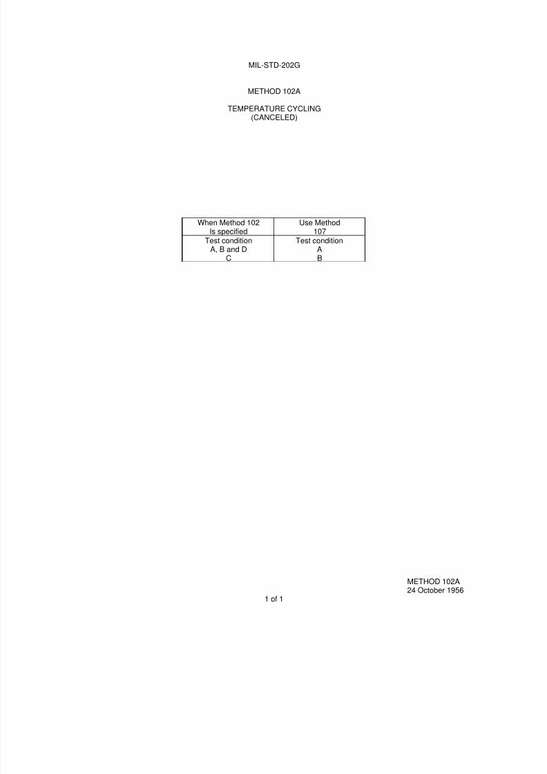
METHOD 102A
TEMPERATURE CYCLING(CANCELED)
When Method 102Is specified
Use Method107
Test condition Test conditionA, B and D A
C B
METHOD 102A24 October 1956
1 of 1

7/29/2019 TEST METHOD STANDARD ELECTRONIC AND ELECTRICAL COMPONENT PARTS
http://slidepdf.com/reader/full/test-method-standard-electronic-and-electrical-component-parts 20/191
7/29/2019 TEST METHOD STANDARD ELECTRONIC AND ELECTRICAL COMPONENT PARTS
http://slidepdf.com/reader/full/test-method-standard-electronic-and-electrical-component-parts 21/191
MIL-STD-202G
METHOD 103B
HUMIDITY (STEADY STATE)
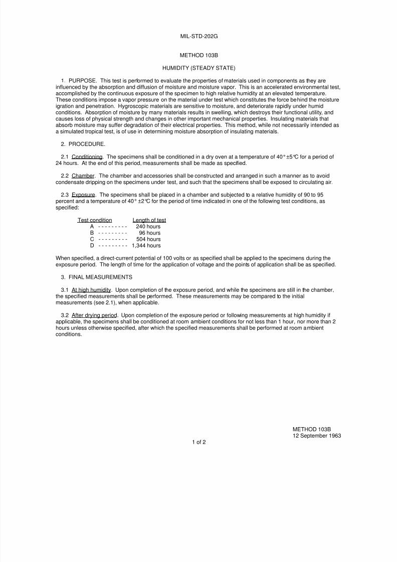
1. PURPOSE. This test is performed to evaluate the properties of materials used in components as they areinfluenced by the absorption and diffusion of moisture and moisture vapor. This is an accelerated environmental test,
accomplished by the continuous exposure of the specimen to high relative humidity at an elevated temperature.These conditions impose a vapor pressure on the material under test which constitutes the force behind the moistureigration and penetration. Hygroscopic materials are sensitive to moisture, and deteriorate rapidly under humidconditions. Absorption of moisture by many materials results in swelling, which destroys their functional utility, andcauses loss of physical strength and changes in other important mechanical properties. Insulating materials thatabsorb moisture may suffer degradation of their electrical properties. This method, while not necessarily intended asa simulated tropical test, is of use in determining moisture absorption of insulating materials.
2. PROCEDURE.
2.1 Conditioning. The specimens shall be conditioned in a dry oven at a temperature of 40° ±5°C for a period of24 hours. At the end of this period, measurements shall be made as specified.
2.2 Chamber. The chamber and accessories shall be constructed and arranged in such a manner as to avoidcondensate dripping on the specimens under test, and such that the specimens shall be exposed to circulating air.
2.3 Exposure. The specimens shall be placed in a chamber and subjected to a relative humidity of 90 to 95percent and a temperature of 40°±2°C for the period of time indicated in one of the following test conditions, asspecified:
Test condition Length of testA - - - - - - - - - 240 hoursB - - - - - - - - - 96 hoursC - - - - - - - - - 504 hoursD - - - - - - - - - 1,344 hours
When specified, a direct-current potential of 100 volts or as specified shall be applied to the specimens during theexposure period. The length of time for the application of voltage and the points of application shall be as specified.
3. FINAL MEASUREMENTS
3.1 At high humidity. Upon completion of the exposure period, and while the specimens are still in the chamber,the specified measurements shall be performed. These measurements may be compared to the initialmeasurements (see 2.1), when applicable.
3.2 After drying period. Upon completion of the exposure period or following measurements at high humidity ifapplicable, the specimens shall be conditioned at room ambient conditions for not less than 1 hour, nor more than 2hours unless otherwise specified, after which the specified measurements shall be performed at room ambientconditions.
METHOD 103B12 September 1963
1 of 2

7/29/2019 TEST METHOD STANDARD ELECTRONIC AND ELECTRICAL COMPONENT PARTS
http://slidepdf.com/reader/full/test-method-standard-electronic-and-electrical-component-parts 22/191
MIL-STD-202G
4. SUMMARY. The following details are to be specified in the individual specification:
a. Measurements after conditioning (see 2.1).
b. Test condition letter (see 2.3).
c. The length of time and points of application of polarizing voltage, if applicable (see 2.3).
d. Final measurements:
(1) At high humidity, if applicable (see 3.1).
(2) After drying period (see 3.2).
METHOD 103B12 September 1963
2
7/29/2019 TEST METHOD STANDARD ELECTRONIC AND ELECTRICAL COMPONENT PARTS
http://slidepdf.com/reader/full/test-method-standard-electronic-and-electrical-component-parts 23/191
MIL-STD-202G
METHOD 104A
IMMERSION
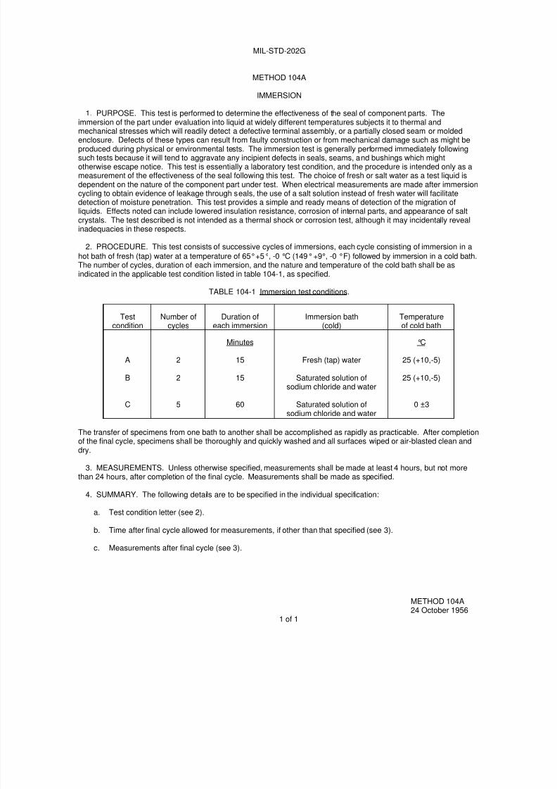
1. PURPOSE. This test is performed to determine the effectiveness of the seal of component parts. Theimmersion of the part under evaluation into liquid at widely different temperatures subjects it to thermal and
mechanical stresses which will readily detect a defective terminal assembly, or a partially closed seam or moldedenclosure. Defects of these types can result from faulty construction or from mechanical damage such as might beproduced during physical or environmental tests. The immersion test is generally performed immediately followingsuch tests because it will tend to aggravate any incipient defects in seals, seams, and bushings which mightotherwise escape notice. This test is essentially a laboratory test condition, and the procedure is intended only as ameasurement of the effectiveness of the seal following this test. The choice of fresh or salt water as a test liquid isdependent on the nature of the component part under test. When electrical measurements are made after immersioncycling to obtain evidence of leakage through seals, the use of a salt solution instead of fresh water will facilitatedetection of moisture penetration. This test provides a simple and ready means of detection of the migration ofliquids. Effects noted can include lowered insulation resistance, corrosion of internal parts, and appearance of saltcrystals. The test described is not intended as a thermal shock or corrosion test, although it may incidentally revealinadequacies in these respects.
2. PROCEDURE. This test consists of successive cycles of immersions, each cycle consisting of immersion in a
hot bath of fresh (tap) water at a temperature of 65°+5°, -0 °C (149°+9°, -0 °F) followed by immersion in a cold bath.
The number of cycles, duration of each immersion, and the nature and temperature of the cold bath shall be asindicated in the applicable test condition listed in table 104-1, as specified.
TABLE 104-1 Immersion test conditions.
Testcondition
Number ofcycles
Duration ofeach immersion
Immersion bath(cold)
Temperatureof cold bath
A
B
C
2
2
5
Minutes
15
15
60
Fresh (tap) water
Saturated solution ofsodium chloride and water
Saturated solution ofsodium chloride and water
°C
25 (+10,-5)
25 (+10,-5)
0 ±3
The transfer of specimens from one bath to another shall be accomplished as rapidly as practicable. After completionof the final cycle, specimens shall be thoroughly and quickly washed and all surfaces wiped or air-blasted clean anddry.
3. MEASUREMENTS. Unless otherwise specified, measurements shall be made at least 4 hours, but not morethan 24 hours, after completion of the final cycle. Measurements shall be made as specified.
4. SUMMARY. The following details are to be specified in the individual specification:
a. Test condition letter (see 2).
b. Time after final cycle allowed for measurements, if other than that specified (see 3).
c. Measurements after final cycle (see 3).
METHOD 104A24 October 1956
1 of 1

7/29/2019 TEST METHOD STANDARD ELECTRONIC AND ELECTRICAL COMPONENT PARTS
http://slidepdf.com/reader/full/test-method-standard-electronic-and-electrical-component-parts 24/191
7/29/2019 TEST METHOD STANDARD ELECTRONIC AND ELECTRICAL COMPONENT PARTS
http://slidepdf.com/reader/full/test-method-standard-electronic-and-electrical-component-parts 25/191
MIL-STD-202G
METHOD 105C
BAROMETRIC PRESSURE (REDUCED)
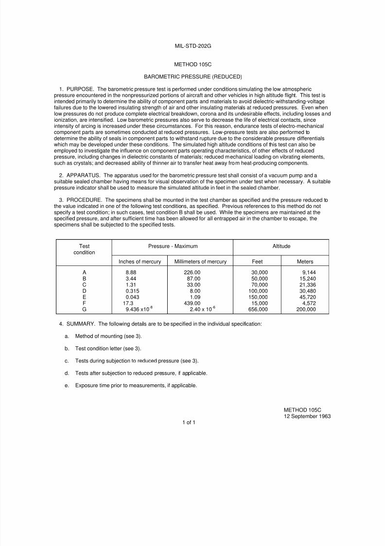
1. PURPOSE. The barometric pressure test is performed under conditions simulating the low atmosphericpressure encountered in the nonpressurized portions of aircraft and other vehicles in high altitude flight. This test isintended primarily to determine the ability of component parts and materials to avoid dielectric-withstanding-voltagefailures due to the lowered insulating strength of air and other insulating materials at reduced pressures. Even whenlow pressures do not produce complete electrical breakdown, corona and its undesirable effects, including losses andionization, are intensified. Low barometric pressures also serve to decrease the life of electrical contacts, sinceintensity of arcing is increased under these circumstances. For this reason, endurance tests of electro-mechanicalcomponent parts are sometimes conducted at reduced pressures. Low-pressure tests are also performed todetermine the ability of seals in component parts to withstand rupture due to the considerable pressure differentialswhich may be developed under these conditions. The simulated high altitude conditions of this test can also beemployed to investigate the influence on component parts operating characteristics, of other effects of reducedpressure, including changes in dielectric constants of materials; reduced mechanical loading on vibrating elements,such as crystals; and decreased ability of thinner air to transfer heat away from heat-producing components.
2. APPARATUS. The apparatus used for the barometric pressure test shall consist of a vacuum pump and a
suitable sealed chamber having means for visual observation of the specimen under test when necessary. A suitablepressure indicator shall be used to measure the simulated altitude in feet in the sealed chamber.
3. PROCEDURE. The specimens shall be mounted in the test chamber as specified and the pressure reduced tothe value indicated in one of the following test conditions, as specified. Previous references to this method do notspecify a test condition; in such cases, test condition B shall be used. While the specimens are maintained at thespecified pressure, and after sufficient time has been allowed for all entrapped air in the chamber to escape, thespecimens shall be subjected to the specified tests.
Testcondition
Pressure - Maximum Altitude
Inches of mercury Millimeters of mercury Feet Meters
ABCDEFG
8.883.441.310.3150.043
17.39.436 x10
-8
226.0087.0033.00
8.001.09
439.002.40 x 10
-6
30,00050,00070,000
100,000150,000
15,000656,000
9,14415,24021,33630,48045,7204,572
200,000
4. SUMMARY. The following details are to be specified in the individual specification:
a. Method of mounting (see 3).
b. Test condition letter (see 3).
c. Tests during subjection to reduced pressure (see 3).
d. Tests after subjection to reduced pressure, if applicable.
e. Exposure time prior to measurements, if applicable.
METHOD 105C12 September 1963
1 of 1

7/29/2019 TEST METHOD STANDARD ELECTRONIC AND ELECTRICAL COMPONENT PARTS
http://slidepdf.com/reader/full/test-method-standard-electronic-and-electrical-component-parts 26/191

7/29/2019 TEST METHOD STANDARD ELECTRONIC AND ELECTRICAL COMPONENT PARTS
http://slidepdf.com/reader/full/test-method-standard-electronic-and-electrical-component-parts 27/191
MIL-STD-202G
METHOD 106G
MOISTURE RESISTANCE
1. PURPOSE. The moisture resistance test is performed for the purpose of evaluating, in an accelerated manner,the resistance of component parts and constituent materials to the deteriorative effects of the high-humidity and heatconditions typical of tropical environments. Most tropical degradation results directly or indirectly from absorption ofmoisture vapor and films by vulnerable insulating materials, and from surface wetting of metals and insulation. Thesephenomena produce many types of deterioration, including corrosion of metals, physical distortion and decompositionof organic materials, leaching out and spending of constituents of materials; and detrimental changes in electricalproperties. This test differs from the steady-state humidity test (method 103 of this standard) and derives its addedeffectiveness in its employment of temperature cycling, which provides alternate periods of condensation and dryingessential to the development of the corrosion processes and, in addition, produces a "breathing" action of moistureinto partially sealed containers. Increased effectiveness is also obtained by use of a higher temperature, whichintensifies the effects of humidity. The test includes low temperature and vibration subcycles (when applicable, see3.4.2) that act as accelerants to reveal otherwise indiscernible evidence of deterioration since stresses caused byfreezing moisture and accentuated by vibration tend to widen cracks and fissures. As a result, the deterioration canbe detected by the measurement of electrical characteristics (including such tests as dielectric withstanding voltageand insulation resistance) or by performance of a test for sealing. Provision is made for the application of a polarizing
voltage across insulation to investigate the possibility of electrolysis, which can promote eventual dielectricbreakdown. This test also provides for electrical loading of certain components, if desired, in order to determine theresistance of current-carrying components, especially fine wires and contacts, to electro-chemical corrosion. Resultsobtained with this test are reproducible and have been confirmed by investigations of field failures. This test hasproven reliable for indicating those parts which are unsuited for tropical field use.
2. APPARATUS.
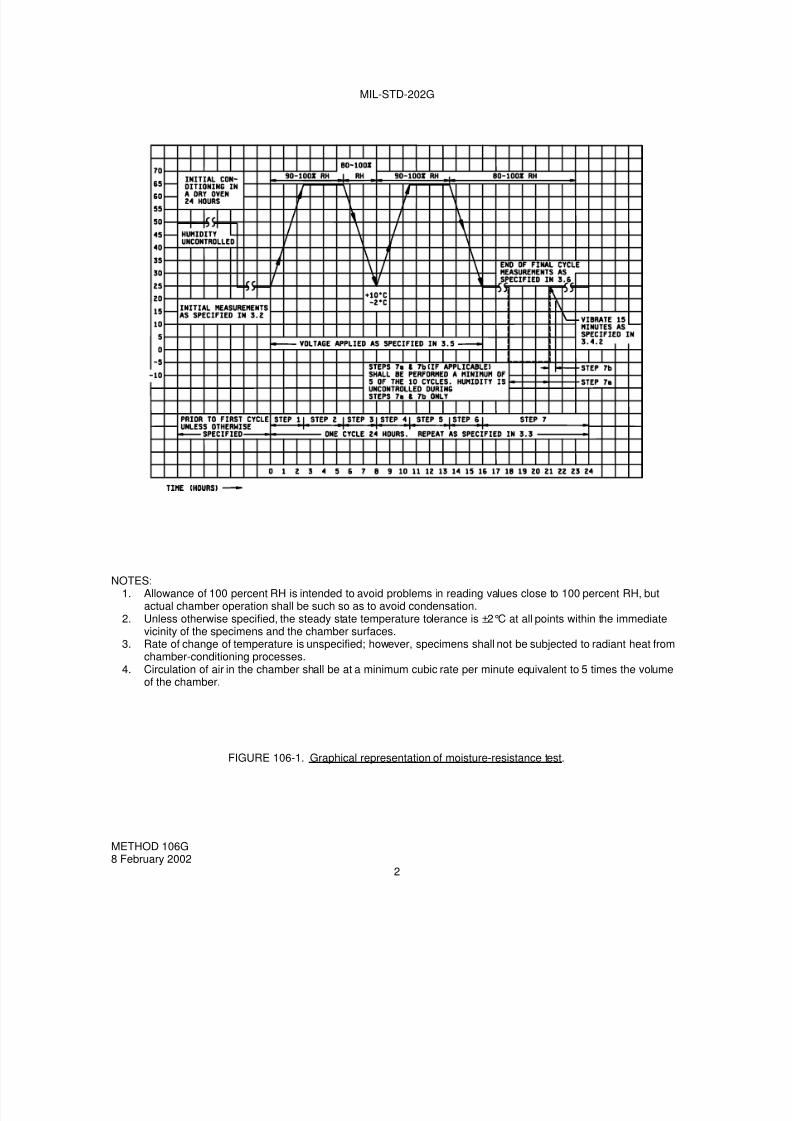
2.1 Chamber. A test chamber shall be used which can meet the temperature and humidity cycling specified onfigure 106-1. The material used to fabricate the platforms and standoffs, which support the specimens, shall be non-reactive in high humidity. Wood or plywood shall not be used because they are resiniferous. Materials shall not beused if they contain formaldehyde or phenol in their composition. Provisions shall be made to prevent condensatefrom the chamber ceiling dripping onto the test specimens.
2.1.1 Opening of the chamber door. During the periods when the humidity is ascending or descending, the
chamber door should not be opened. If the chamber door must be opened, it should be opened during the 16th hourthrough the 24th hour of an individual cycle. While the chamber is at 25°C (77°F), and the relative humidity tolerancemust be maintained, the chamber door should be opened only for a short period of time.
2.1.2 Water. Steam, or distilled and demineralized, or deionized water, having a pH value between 6.0 and 7.2 at23°C (73.4°F) shall be used to obtain the specified humidity. No rust or corrosive contaminants shall be imposed onthe test specimens by the test facility.
3. PROCEDURE.
3.1 Mounting. Specimens shall be mounted by their normal mounting means, in their normal mounting position,but shall be positioned so that they do not contact each other, and so that each specimen receives essentially thesame degree of humidity.
3.2 Initial measurements. Prior to step 1 of the first cycle, the specified initial measurements shall be made atroom ambient conditions, or as specified.
METHOD 106G8 February 2002
1 of 4
7/29/2019 TEST METHOD STANDARD ELECTRONIC AND ELECTRICAL COMPONENT PARTS
http://slidepdf.com/reader/full/test-method-standard-electronic-and-electrical-component-parts 28/191
MIL-STD-202G
NOTES:1. Allowance of 100 percent RH is intended to avoid problems in reading values close to 100 percent RH, but
actual chamber operation shall be such so as to avoid condensation.2. Unless otherwise specified, the steady state temperature tolerance is ±2°C at all points within the immediate
vicinity of the specimens and the chamber surfaces.3. Rate of change of temperature is unspecified; however, specimens shall not be subjected to radiant heat from
chamber-conditioning processes.4. Circulation of air in the chamber shall be at a minimum cubic rate per minute equivalent to 5 times the volume
of the chamber.
FIGURE 106-1. Graphical representation of moisture-resistance test.
METHOD 106G8 February 2002
2

7/29/2019 TEST METHOD STANDARD ELECTRONIC AND ELECTRICAL COMPONENT PARTS
http://slidepdf.com/reader/full/test-method-standard-electronic-and-electrical-component-parts 29/191
MIL-STD-202G
3.3 Number of cycles. Specimens shall be subjected to 10 continuous cycles, each as shown on figure 106-1. Inthe event of no more than one unintentional test interruption (power interruption or equipment failure) prior to thecompletion of the specified number of cycles (except for the last cycle), the cycle shall be repeated and the test may
continue. Unintentional interruptions occurring during the last cycle require a repeat of the cycle plus an additionaluninterrupted cycle. Any intentional interruption, or any unintentional interruption of greater than 24 hours requires acomplete retest.
3.4 Subcycle of step 7. During at least 5 of the 10 cycles, a low temperature subcycle and, if applicable, avibration subcycle shall be performed.
3.4.1 Step 7a. At least 1 hour but not more than 4 hours after step 7 begins, the specimens shall be eitherremoved from the humidity chamber, or the temperature of the chamber shall be reduced. Specimens shall then be
conditioned at -10°C ±2°C (14°F ±3.6°F) with humidity not controlled, for 3 hours minimum as indicated on figure106-1. When a separate cold chamber is not used, care should be taken to assure that the specimens are held at
-10°C ±2°C (14°F ±3.6°F) for the full 3 hour period. (If step 7b is not applicable, the specimens shall be returned to
25°C (77°F) at 80 percent relative humidity minimum and kept there until the next cycle begins.)
3.4.2 Step 7b (when applicable). Within 15 minutes after completion of step 7a and with humidity not controlled and
temperature at room ambient, specimens shall be vibrated for 15 minutes, using a simple harmonic motion having anamplitude of 0.03 inch (0.76 mm), (0.06 inch (1.52 mm) maximum total excursion), the frequency being varieduniformly between the approximate limits of 10 and 55 hertz (Hz). The entire frequency range, from 10 to 55 Hz and
return to 10 Hz, shall be traversed in approximately 1 minute. After step 7b, the specimens shall be returned to 25°C
(77°F) at 80 percent relative humidity minimum and kept there until the next cycle begins.
NOTE: Step 7b is not applicable to parts that include test schedules with vibration requirements (such as method201 or method 204 of this standard). These parts must routinely be subjected to, and pass, these requirements.
NOTE: Allowance of 100 percent RH is intended to avoid problems in reading values close to 100 percent, butactual chamber operation shall be such so as to avoid condensation.
3.5 Polarization and load. When applicable, polarization voltage shall be 100 volts dc, or as specified. Theloading voltage shall be as specified.
3.6 Final measurements.
3.6.1 At high humidity. Upon completion of step 6 of the final cycle (or step 7 if the subcycle of 3.4 is performedduring the tenth cycle), when measurements at high humidity are specified, the specimens shall be maintained at a
temperature of 25°C ±2°C (77°F ±3.6°F), and a RH of 80 percent minimum for a period of 1½ to 3½ hours, afterwhich the specified measurements shall be made. Due to the difficulty in making measurements under high humidityconditions, the individual specification shall specify the particular precautions to be followed in making measurementsunder such conditions.
(NOTE: Allowance of 100 percent RH is intended to avoid problems in reading values close to 100 percent, butactual chamber operation shall be such so as to avoid condensation.)
3.6.2 After high humidity. Upon removal from humidity chamber, final measurements shall be made within aperiod of 1 to 2 hours after the final cycle. During final measurements, specimens shall not be subjected to any
means of artificial drying.
3.6.3 After drying period. Following step 6 of the final cycle (or step 7 if the subcycle of 3.4 is performed during thetenth cycle), or following measurements at high humidity, if applicable, specimens shall be conditioned for 24 hours atthe ambient conditions specified for the initial measurements (see 3.2) after which the specified measurements shallbe made. Measurements may be made during the 24 hour conditioning period; however, any failures which occurshall be considered as failures and shall not be retested later for the purpose of obtaining an acceptable result.
METHOD 106G8 February 2002
3

7/29/2019 TEST METHOD STANDARD ELECTRONIC AND ELECTRICAL COMPONENT PARTS
http://slidepdf.com/reader/full/test-method-standard-electronic-and-electrical-component-parts 30/191
MIL-STD-202G
4. SUMMARY: The following details are to be specified in the individual specification:
a. Initial measurements and conditions, if other than room ambient (see 3.2).
b. When applicable, the polarization voltage if other than 100 volts (see 3.5).
c. Loading voltage (see 3.5).
d. Final measurements and measurement conditions (see 3.6).
METHOD 106G 8 February 2002
4
7/29/2019 TEST METHOD STANDARD ELECTRONIC AND ELECTRICAL COMPONENT PARTS
http://slidepdf.com/reader/full/test-method-standard-electronic-and-electrical-component-parts 31/191
MIL-STD-202G
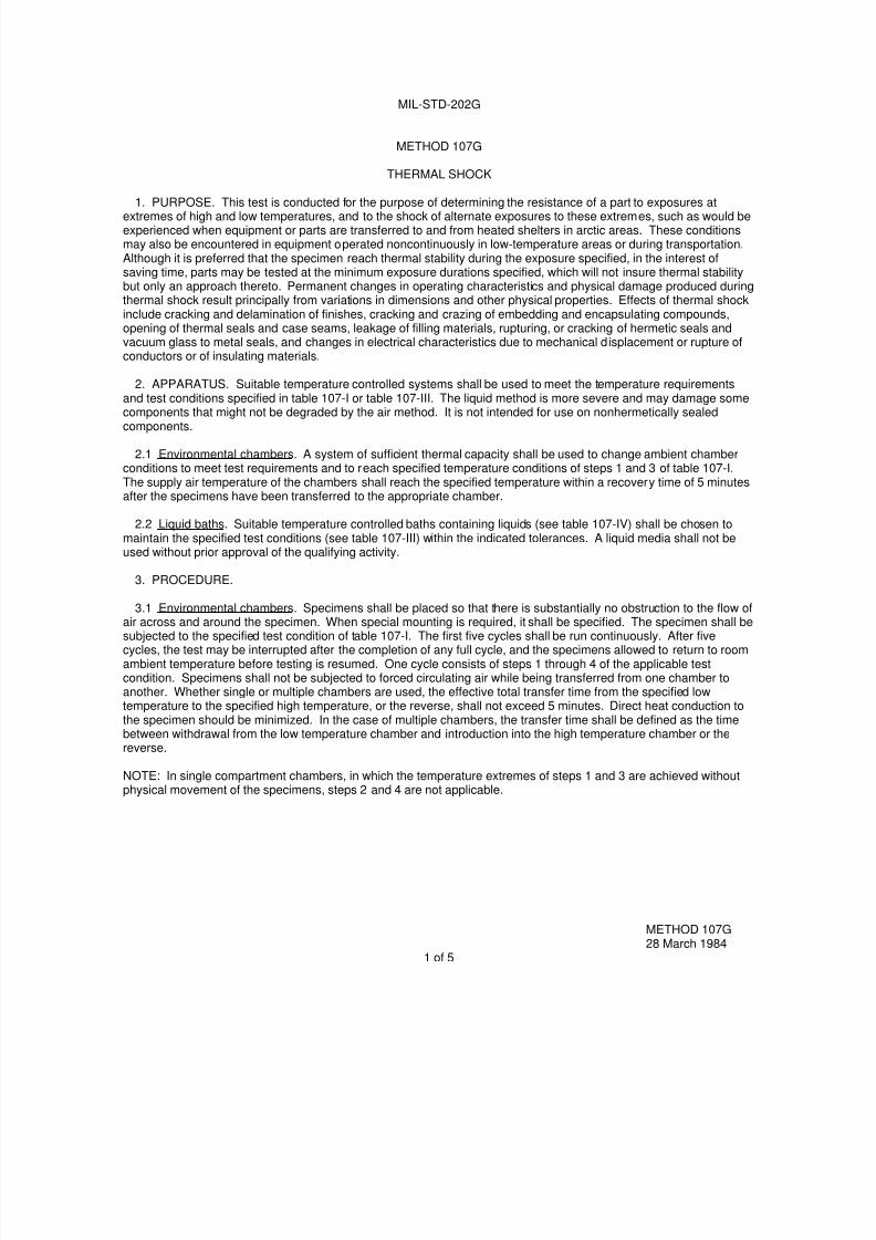
METHOD 107G
THERMAL SHOCK
1. PURPOSE. This test is conducted for the purpose of determining the resistance of a part to exposures atextremes of high and low temperatures, and to the shock of alternate exposures to these extremes, such as would beexperienced when equipment or parts are transferred to and from heated shelters in arctic areas. These conditionsmay also be encountered in equipment operated noncontinuously in low-temperature areas or during transportation.Although it is preferred that the specimen reach thermal stability during the exposure specified, in the interest ofsaving time, parts may be tested at the minimum exposure durations specified, which will not insure thermal stabilitybut only an approach thereto. Permanent changes in operating characteristics and physical damage produced duringthermal shock result principally from variations in dimensions and other physical properties. Effects of thermal shockinclude cracking and delamination of finishes, cracking and crazing of embedding and encapsulating compounds,opening of thermal seals and case seams, leakage of filling materials, rupturing, or cracking of hermetic seals andvacuum glass to metal seals, and changes in electrical characteristics due to mechanical displacement or rupture ofconductors or of insulating materials.
2. APPARATUS. Suitable temperature controlled systems shall be used to meet the temperature requirementsand test conditions specified in table 107-I or table 107-III. The liquid method is more severe and may damage some
components that might not be degraded by the air method. It is not intended for use on nonhermetically sealedcomponents.
2.1 Environmental chambers. A system of sufficient thermal capacity shall be used to change ambient chamberconditions to meet test requirements and to reach specified temperature conditions of steps 1 and 3 of table 107-I.The supply air temperature of the chambers shall reach the specified temperature within a recovery time of 5 minutesafter the specimens have been transferred to the appropriate chamber.
2.2 Liquid baths. Suitable temperature controlled baths containing liquids (see table 107-IV) shall be chosen tomaintain the specified test conditions (see table 107-III) within the indicated tolerances. A liquid media shall not beused without prior approval of the qualifying activity.
3. PROCEDURE.
3.1 Environmental chambers. Specimens shall be placed so that there is substantially no obstruction to the flow of
air across and around the specimen. When special mounting is required, it shall be specified. The specimen shall besubjected to the specified test condition of table 107-I. The first five cycles shall be run continuously. After fivecycles, the test may be interrupted after the completion of any full cycle, and the specimens allowed to return to roomambient temperature before testing is resumed. One cycle consists of steps 1 through 4 of the applicable testcondition. Specimens shall not be subjected to forced circulating air while being transferred from one chamber toanother. Whether single or multiple chambers are used, the effective total transfer time from the specified lowtemperature to the specified high temperature, or the reverse, shall not exceed 5 minutes. Direct heat conduction tothe specimen should be minimized. In the case of multiple chambers, the transfer time shall be defined as the timebetween withdrawal from the low temperature chamber and introduction into the high temperature chamber or thereverse.
NOTE: In single compartment chambers, in which the temperature extremes of steps 1 and 3 are achieved withoutphysical movement of the specimens, steps 2 and 4 are not applicable.
METHOD 107G28 March 1984
1 of 5

7/29/2019 TEST METHOD STANDARD ELECTRONIC AND ELECTRICAL COMPONENT PARTS
http://slidepdf.com/reader/full/test-method-standard-electronic-and-electrical-component-parts 32/191
MIL-STD-202G
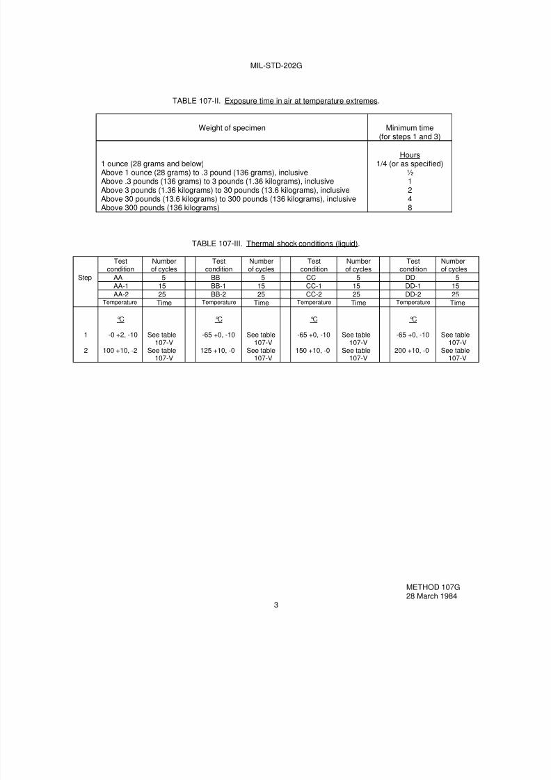
3.2 Liquid baths. Specimens shall be immersed in a suitable liquid that shall be approved by the qualifying activity(see table 107-IV), at the temperature in step 1 of the specified test condition (see table 107-III) for the time specifiedin table 107-V. Immediately upon the conclusion of step 1, the device shall be transferred to a suitable liquid at the
temperature specified in step 2 of the specified test condition. The device shall remain at the high temperature for thetime specified in table 107-V. These two steps, step 1 and 2, constitute one cycle of the applicable test condition.Repeat the required number of cycles without interruption as specified in table 107-III. Transfer time from low to hightemperature and from high to low temperature shall be less than 10 seconds.
TABLE 107-I. Thermal shock test conditions (air).
Testcondition
Number ofcycles
Testcondition
Number ofcycles
Testcondition
Number ofcycles
Step A 5 B 5 C 5
A-1 25 B-1 25 C-1 25
A-2 50 B-2 50 C-2 50
A-3 100 B-3 100 C-3 100
Temperature Time Temperature Time Temperature Time
1
2
3
4
°C-55 +0, -3
25 +10, -5
85 +3, -0
25 +10, -5
See table107-II
5 minutesmaximum
See table107-II
5 minutesmaximum
°C-65 +0, -5
25 +10, -5
125 +3, -0
25 +10, -5
See table107-II
5 minutesmaximum
See table107-II
5 minutesmaximum
°C-65 +0, -5
25 +10, -5
200 +5, -0
25 +10, -5
See table107-II
5 minutesmaximum
See table107-II
5 minutesmaximum
Testcondition
Number ofcycles
Testcondition
Number ofcycles
Testcondition
Number ofcycles
Step D 5 E 5 F 5D-1 25 E-1 25 F-1 25
D-2 50 E-2 50 F-2 50
D-3 100 E-3 100 F-3 100
Temperature Time Temperature Time Temperature Time
1
2
3
4
°C-65 +0, -5
25 +10, -5
350 +5, -0
25 +10, -5
See table107-II
5 minutesmaximum
See table107-II
5 minutesmaximum
°C-65 +0, -5
25 +10, -5
500 +5, -0
25 +10, -5
See table107-II
5 minutesmaximum
See table107-II
5 minutesmaximum
°C-65 +0, -5
25 +10, -5
150 +3, -0
25 +10, -5
See table107-II
5 minutesmaximum
See table107-II
5 minutesmaximum
METHOD 107G28 March 1984
2
7/29/2019 TEST METHOD STANDARD ELECTRONIC AND ELECTRICAL COMPONENT PARTS
http://slidepdf.com/reader/full/test-method-standard-electronic-and-electrical-component-parts 33/191
MIL-STD-202G
TABLE 107-II. Exposure time in air at temperature extremes.
Weight of specimen Minimum time(for steps 1 and 3)
1 ounce (28 grams and below)Above 1 ounce (28 grams) to .3 pound (136 grams), inclusiveAbove .3 pounds (136 grams) to 3 pounds (1.36 kilograms), inclusiveAbove 3 pounds (1.36 kilograms) to 30 pounds (13.6 kilograms), inclusiveAbove 30 pounds (13.6 kilograms) to 300 pounds (136 kilograms), inclusiveAbove 300 pounds (136 kilograms)
Hours1/4 (or as specified)
½1248
TABLE 107-III. Thermal shock conditions (liquid).
Testcondition
Numberof cycles
Testcondition
Numberof cycles
Testcondition
Numberof cycles
Testcondition
Numberof cycles
Step AA 5 BB 5 CC 5 DD 5
AA-1 15 BB-1 15 CC-1 15 DD-1 15
AA-2 25 BB-2 25 CC-2 25 DD-2 25Temperature Time Temperature Time Temperature Time Temperature Time
1
2
°C
-0 +2, -10
100 +10, -2
See table107-V
See table107-V
°C
-65 +0, -10
125 +10, -0
See table107-V
See table107-V
°C
-65 +0, -10
150 +10, -0
See table107-V
See table107-V
°C
-65 +0, -10
200 +10, -0
See table107-V
See table107-V
METHOD 107G28 March 1984
3
7/29/2019 TEST METHOD STANDARD ELECTRONIC AND ELECTRICAL COMPONENT PARTS
http://slidepdf.com/reader/full/test-method-standard-electronic-and-electrical-component-parts 34/191
MIL-STD-202G
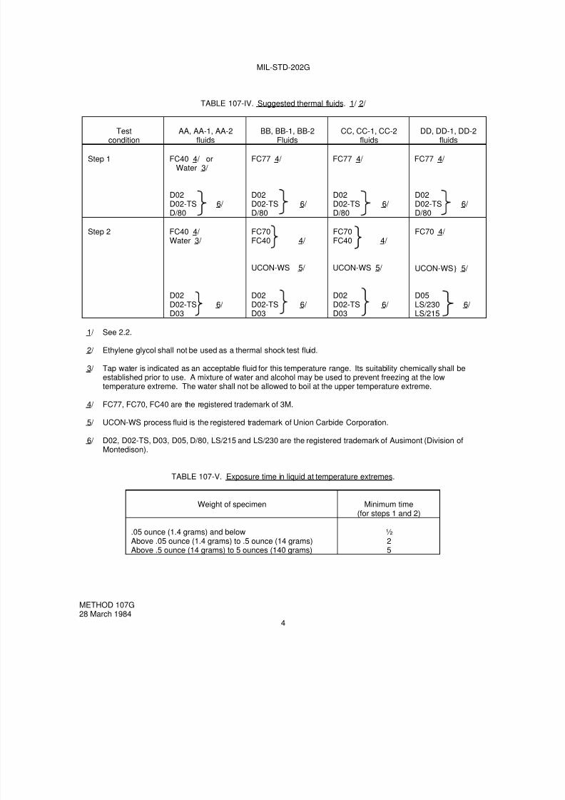
TABLE 107-IV. Suggested thermal fluids. 1/ 2/
Testcondition
AA, AA-1, AA-2fluids
BB, BB-1, BB-2Fluids
CC, CC-1, CC-2fluids
DD, DD-1, DD-2fluids
Step 1 FC40 4/ orWater 3/
FC77 4/ FC77 4/ FC77 4/
D02D02-TS 6/ D/80
D02D02-TS 6/ D/80
D02D02-TS 6/ D/80
D02D02-TS 6/ D/80
Step 2 FC40 4/ Water 3/
FC70FC40 4/
FC70FC40 4/
FC70 4/
UCON-WS 5/ UCON-WS 5/ UCON-WS} 5/
D02D02-TS 6/ D03
D02D02-TS 6/ D03
D02D02-TS 6/ D03
D05LS/230 6/ LS/215
1/ See 2.2.
2/ Ethylene glycol shall not be used as a thermal shock test fluid.
3/ Tap water is indicated as an acceptable fluid for this temperature range. Its suitability chemically shall beestablished prior to use. A mixture of water and alcohol may be used to prevent freezing at the lowtemperature extreme. The water shall not be allowed to boil at the upper temperature extreme.
4/ FC77, FC70, FC40 are the registered trademark of 3M.
5/ UCON-WS process fluid is the registered trademark of Union Carbide Corporation.
6/ D02, D02-TS, D03, D05, D/80, LS/215 and LS/230 are the registered trademark of Ausimont (Division ofMontedison).
TABLE 107-V. Exposure time in liquid at temperature extremes.
Weight of specimen Minimum time(for steps 1 and 2)
.05 ounce (1.4 grams) and belowAbove .05 ounce (1.4 grams) to .5 ounce (14 grams)Above .5 ounce (14 grams) to 5 ounces (140 grams)
½25
METHOD 107G28 March 1984
4
7/29/2019 TEST METHOD STANDARD ELECTRONIC AND ELECTRICAL COMPONENT PARTS
http://slidepdf.com/reader/full/test-method-standard-electronic-and-electrical-component-parts 35/191
MIL-STD-202G
4. MEASUREMENTS. Specified measurements shall be made prior to the first cycle and upon completion of thefinal cycle, except that failures shall be based on measurements made after the specimen has stabilized at roomtemperature following the final cycle.
5. SUMMARY. The following details are to be specified in the individual specification:
a. Recovery time if other than 5 minutes (see 2.1).
b. Special mounting, if applicable (see 3).
c. Type test (air or liquid) and test condition (see 3).
d. Transfer time if other than specified in 3.1 or 3.2.
e. Measurements before and after cycling (see 4).
METHOD 107G28 March 1984
5

7/29/2019 TEST METHOD STANDARD ELECTRONIC AND ELECTRICAL COMPONENT PARTS
http://slidepdf.com/reader/full/test-method-standard-electronic-and-electrical-component-parts 36/191
7/29/2019 TEST METHOD STANDARD ELECTRONIC AND ELECTRICAL COMPONENT PARTS
http://slidepdf.com/reader/full/test-method-standard-electronic-and-electrical-component-parts 37/191
MIL-STD-202G
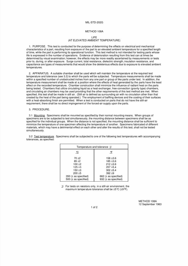
METHOD 108A
LIFE(AT ELEVATED AMBIENT TEMPERATURE)
1. PURPOSE. This test is conducted for the purpose of determining the effects on electrical and mechanicalcharacteristics of a part, resulting from exposure of the part to an elevated ambient temperature for a specified lengthof time, while the part is performing its operational function. This test method is not intended for testing parts whoselife is expressed in the number of operations. Evidence of deterioration resulting from this test can at times bedetermined by visual examination; however, the effects may be more readily ascertained by measurements or testsprior to, during, or after exposure. Surge current, total resistance, dielectric strength, insulation resistance, andcapacitance are types of measurements that would show the deleterious effects due to exposure to elevated ambienttemperatures.
2. APPARATUS. A suitable chamber shall be used which will maintain the temperature at the required testtemperature and tolerance (see 3.2) to which the parts will be subjected. Temperature measurements shall be madewithin a specified number of unobstructed inches from any one part or group of like parts under test. In addition, thetemperature measurement shall be made at a position where the effects of heat generated by the parts have the leasteffect on the recorded temperature. Chamber construction shall minimize the influence of radiant heat on the parts
being tested. Chambers that utilize circulating liquid as a heat exchanger, free-convection (gravity type) chambers,and circulating air chambers may be used providing that the other requirements of this test method are met. Whenspecified, this test shall be made in still air. (Still air is defined as surrounding air with no circulation other than thatcreated by the heat of the part being operated.) The employment of baffling devices and the coating of their surfaceswith a heat-absorbing finish are permitted. When a test is conducted on parts that do not have the still-airrequirement, there shall be no direct impingement of the forced-air supply upon the parts.
3. PROCEDURE.
3.1 Mounting. Specimens shall be mounted as specified by their normal mounting means. When groups ofspecimens are to be subjected to test simultaneously, the mounting distance between specimens shall be asspecified for the individual groups. When the distance is not specified, the mounting distance shall be sufficient tominimize the temperature of one specimen affecting the temperature of another. Specimens fabricated of differentmaterials, which may have a detrimental effect on each other and alter the results of this test, shall not be testedsimultaneously.
3.2 Test temperature. Specimens shall be subjected to one of the following test temperatures with accompanyingtolerances, as specified:
Temperature and tolerance 1/
°C
70 ±285 ±2
100 ±2125 ±3150 ±3200 ±5
350 (± as specified)500 (± as specified)
°F
158 ±3.6185 ±3.6212 ±3.6257 ±5.4302 ±5.4392 ±9
662 (± as specified)932 (± as specified)
1/ For tests on resistors only, in a still-air environment, themaximum temperature tolerance shall be ±5°C (±9°F).
METHOD 108A12 September 1963
1 of 2
7/29/2019 TEST METHOD STANDARD ELECTRONIC AND ELECTRICAL COMPONENT PARTS
http://slidepdf.com/reader/full/test-method-standard-electronic-and-electrical-component-parts 38/191
MIL-STD-202G
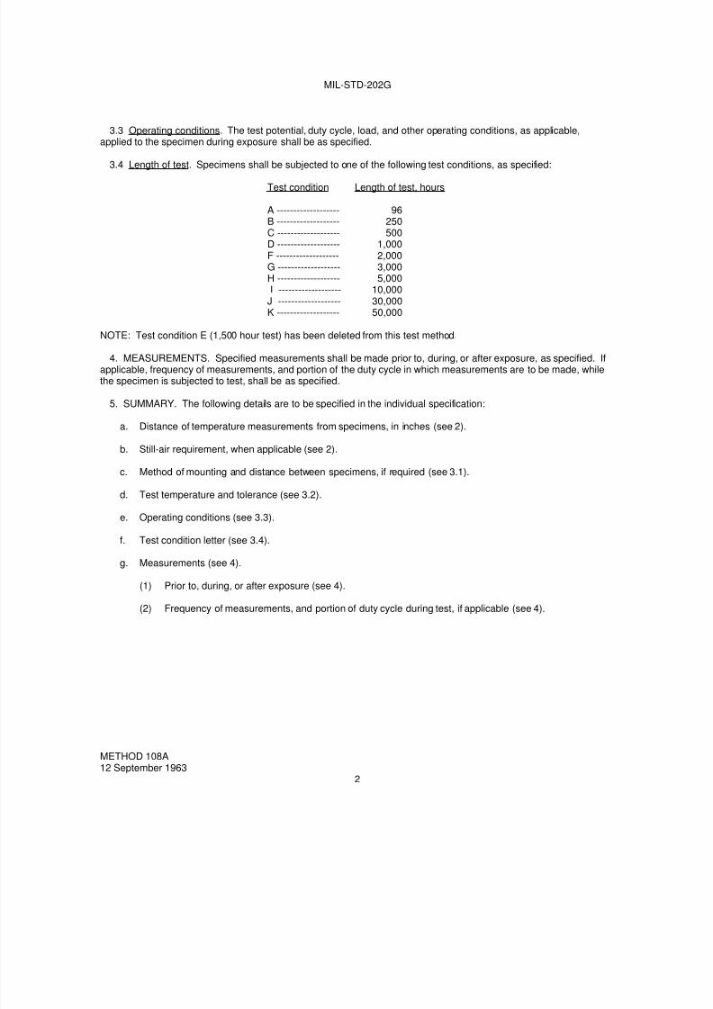
3.3 Operating conditions. The test potential, duty cycle, load, and other operating conditions, as applicable,applied to the specimen during exposure shall be as specified.
3.4 Length of test. Specimens shall be subjected to one of the following test conditions, as specified:
Test condition Length of test, hours
A ------------------- 96B ------------------- 250C ------------------- 500D ------------------- 1,000F ------------------- 2,000G ------------------- 3,000H ------------------- 5,000I ------------------- 10,000
J ------------------- 30,000K ------------------- 50,000
NOTE: Test condition E (1,500 hour test) has been deleted from this test method.
4. MEASUREMENTS. Specified measurements shall be made prior to, during, or after exposure, as specified. Ifapplicable, frequency of measurements, and portion of the duty cycle in which measurements are to be made, whilethe specimen is subjected to test, shall be as specified.
5. SUMMARY. The following details are to be specified in the individual specification:
a. Distance of temperature measurements from specimens, in inches (see 2).
b. Still-air requirement, when applicable (see 2).
c. Method of mounting and distance between specimens, if required (see 3.1).
d. Test temperature and tolerance (see 3.2).
e. Operating conditions (see 3.3).
f. Test condition letter (see 3.4).
g. Measurements (see 4).
(1) Prior to, during, or after exposure (see 4).
(2) Frequency of measurements, and portion of duty cycle during test, if applicable (see 4).
METHOD 108A12 September 1963
2
7/29/2019 TEST METHOD STANDARD ELECTRONIC AND ELECTRICAL COMPONENT PARTS
http://slidepdf.com/reader/full/test-method-standard-electronic-and-electrical-component-parts 39/191
MIL-STD-202G
METHOD 109C
EXPLOSION
1. PURPOSE. The purpose of this method is to determine if a part, while operating, will ignite an ambientexplosive atmosphere. This environment is prevalent in aircraft; therefore, the test is conducted at ground level andvarious reduced barometric pressures. The parts subjected to this type of test are not enclosed in casings designedto prevent flame or explosion propagation.
2. APPARATUS.
2.1 Test facility. The test apparatus consists of a test chamber or cabinet together with associated equipment,safety provisions, and auxiliary instrumentation necessary to establish, maintain, and monitor the specified testconditions. The chamber should be equipped with a system for mixing and circulation of the explosive air-fuelmixture, a means to ignite the air-fuel mixture such as a spark-gap device, as well as a means to collect anddetermine the explosiveness of a sample of the mixture such as a spark gap or glow plug ignition source withsufficient energy to ignite a 3.82 percent hexane mixture. An alternative method of determining the explosivecharacteristics of the vapor is use of a calibrated explosive gas meter that verifies the degree of explosiveness andthe concentration of the air-fuel mixture. The chamber or cabinet should include provisions for the electrical and
mechanical operation of the specimen under test.
2.1.1 Test facility performance requirements.
2.1.1.1 Chamber design pressure. The test chamber shall be capable of withstanding any explosion pressure upto and including 300 pounds per square inch (2 megapascals).
2.1.1.2 Pressure altitude. The test chamber shall be capable of maintaining any desired pressure altitude from
sea level to 60,000 feet (18,250 meters) ± 2 percent.
2.1.1.3 Chamber air temperature. The air temperature within the test chamber shall be uniform and shall be
controllable between 20°C ± 3°C and 240°C ± 3°C.
2.2 Fuel. Unless otherwise specified, the fuel for explosive atmosphere testing shall be the single-componenthydrocarbon n-hexane, either reagent grade or 95% n-hexane with 5% other hexane isomers. This fuel is used sinceits ignition properties for flammable atmosphere testing are equal to or more sensitive than the similar properties ofboth 100/130 octane aviation gasoline, JP-4, and JP-8 jet engine fuel. Optimum mixtures of n-hexane and air will
ignite from hot-spot temperatures as low as 223°C (433°F) while optimum JP-4 jet engine fuel-air mixtures require a
minimum temperature of 230°C (445°F) for auto-ignition, and 100/130 octane aviation gasoline and air requires
441°C (825°F) for hot-spot ignition. Minimum spark energy inputs for ignition of optimum fuel vapor and air mixturesare essentially the same for n-hexane and for 100/130 octane aviation gasoline. Much higher minimum spark energyinput is required to ignite JP-4 or JP-8 jet engine fuel and air mixtures. Use of fuels other than hexane is notrecommended. CAUTION: If the individual specification allows the use of an alternate fuel, the specification mustalso provide all the specific details associated with the alternate fuel, such as safety precautions and fuel-air mixtureequation.
2.3 Fuel vapor mixture. Use a homogeneous fuel-air mixture in the correct fuel-air ratios for the explosiveatmosphere test. Fuel weight calculated to total 3.8 percent by volume of the test atmosphere represents 1.8stoichiometric equivalents of n-hexane in air, giving a mixture needing only minimum energy for ignition. This yields
an air/vapor ratio (AVR) of 8.33 by weight.
METHOD 109C 8 February 2002
1 of 4
7/29/2019 TEST METHOD STANDARD ELECTRONIC AND ELECTRICAL COMPONENT PARTS
http://slidepdf.com/reader/full/test-method-standard-electronic-and-electrical-component-parts 40/191
MIL-STD-202G
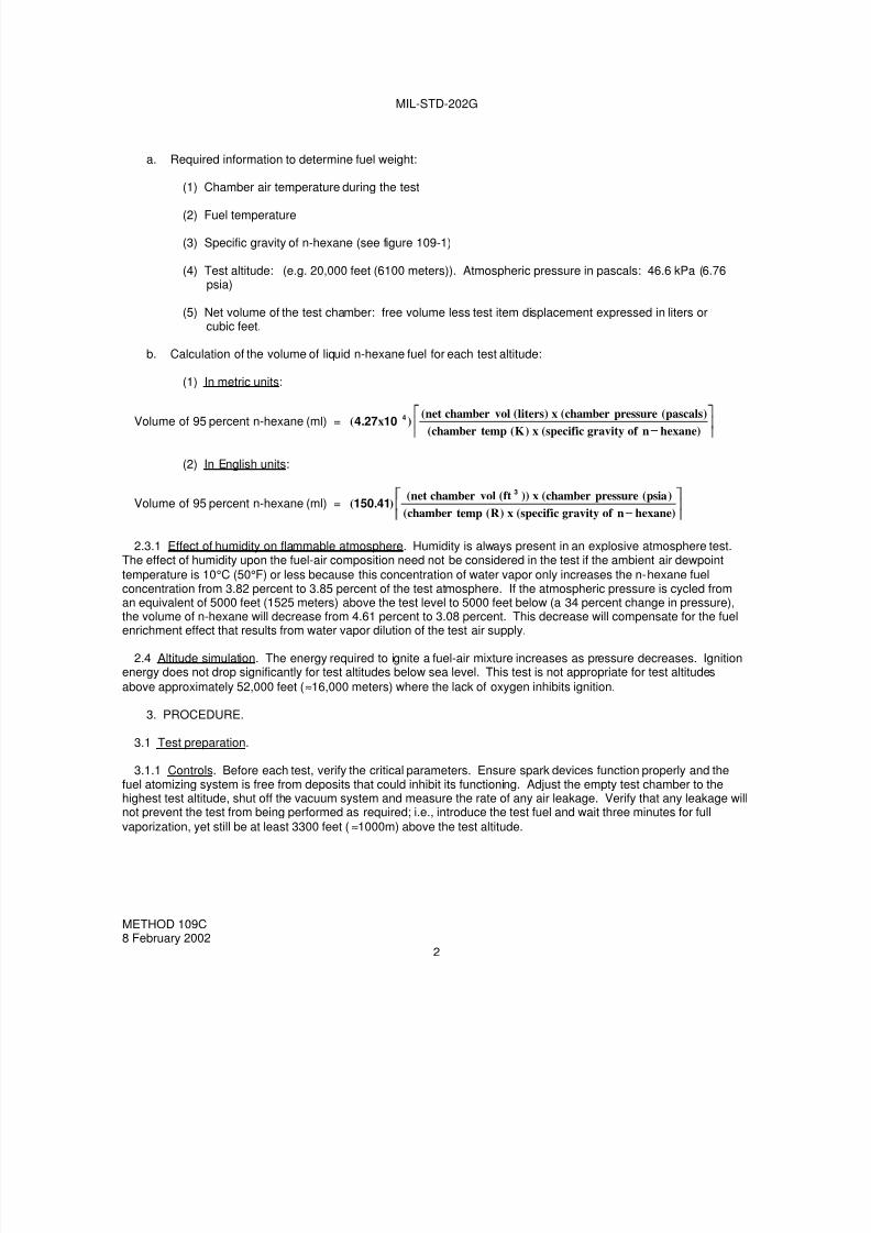
a. Required information to determine fuel weight:
(1) Chamber air temperature during the test
(2) Fuel temperature
(3) Specific gravity of n-hexane (see figure 109-1)
(4) Test altitude: (e.g. 20,000 feet (6100 meters)). Atmospheric pressure in pascals: 46.6 kPa (6.76psia)
(5) Net volume of the test chamber: free volume less test item displacement expressed in liters orcubic feet.
b. Calculation of the volume of liquid n-hexane fuel for each test altitude:
(1) In metric units:
Volume of 95 percent n-hexane (ml) =)hexanenof gravityspecific(x)K(tempchamber(
)pascals(pressurechamber(x)liters(volchambernet()x.( 410274
(2) In English units:
Volume of 95 percent n-hexane (ml) =)hexanenof gravityspecific(x)R(tempchamber(
)psia(pressurechamber(x))ft(volchambernet().(
3
41150
2.3.1 Effect of humidity on flammable atmosphere. Humidity is always present in an explosive atmosphere test.The effect of humidity upon the fuel-air composition need not be considered in the test if the ambient air dewpoint
temperature is 10°C (50°F) or less because this concentration of water vapor only increases the n-hexane fuelconcentration from 3.82 percent to 3.85 percent of the test atmosphere. If the atmospheric pressure is cycled froman equivalent of 5000 feet (1525 meters) above the test level to 5000 feet below (a 34 percent change in pressure),
the volume of n-hexane will decrease from 4.61 percent to 3.08 percent. This decrease will compensate for the fuelenrichment effect that results from water vapor dilution of the test air supply.
2.4 Altitude simulation. The energy required to ignite a fuel-air mixture increases as pressure decreases. Ignitionenergy does not drop significantly for test altitudes below sea level. This test is not appropriate for test altitudes
above approximately 52,000 feet (≈16,000 meters) where the lack of oxygen inhibits ignition.
3. PROCEDURE.
3.1 Test preparation.
3.1.1 Controls. Before each test, verify the critical parameters. Ensure spark devices function properly and thefuel atomizing system is free from deposits that could inhibit its functioning. Adjust the empty test chamber to thehighest test altitude, shut off the vacuum system and measure the rate of any air leakage. Verify that any leakage willnot prevent the test from being performed as required; i.e., introduce the test fuel and wait three minutes for full
vaporization, yet still be at least 3300 feet (≈1000m) above the test altitude.
METHOD 109C8 February 2002
2

7/29/2019 TEST METHOD STANDARD ELECTRONIC AND ELECTRICAL COMPONENT PARTS
http://slidepdf.com/reader/full/test-method-standard-electronic-and-electrical-component-parts 41/191
MIL-STD-202G
3.1.1.2 Mounting. The specimen to be tested shall be mounted in the test chamber in such a manner that normalelectrical operation is possible and so that the mechanical controls may be operated through the pressure seals fromthe exterior of the chamber. All external covers of the test specimen shall be removed or opened to insure adequate
circulation of the explosive mixture. The test specimen shall then be operated to determine that it is functioningproperly and to observe the location of any sparking or high temperature spots that may constitute potential explosionhazards.
3.1.2 Loading. Applicable mechanical and electrical loads applied to the specimen shall be as specified in theindividual specification. Proper precaution shall be taken to duplicate the normal load in respect to torque, voltage,current, inductive reactance, etc. In all instances it shall be considered preferable to operate the specimen as itnormally functions during service use.
3.2 Test execution. The following provides the procedural steps for execution of the explosive atmosphere test;
a. With the test item installed, the test chamber shall be sealed and the test item and chamber inner walls
stabilized to 71°C ±3°C (160°F ±5°F), or to a lower temperature as specified, if the specimen is designed tooperate at a lower temperature.
b. Adjust the chamber air pressure to simulate the desired test altitude (see 3.3) plus an additional 10,000 feetto allow for introducing, vaporizing, and mixing the fuel with the air as described in 2.3.
c. Slowly introduce the required volume of n-hexane into the test chamber.
d. Circulate the test atmosphere and continue to reduce the simulated chamber altitude for at least threeminutes to allow for complete vaporization of fuel and the development of a homogeneous mixture.
e. At a pressure equivalent to 5,000 feet (1525 meters) above the test altitude, verify the potentialexplosiveness of the fuel-air vapor by attempting to ignite a sample of the mixture taken from the testchamber by using a spark-gap device or glow plug ignition source with sufficient energy to ignite a 3.82percent hexane mixture. If ignition does not occur, purge the chamber of the fuel vapor and repeat steps athrough e. (An alternative method of determining the explosive characteristics of the vapor is by using acalibrated explosive gas meter that verifies the degree of explosiveness and the concentration of the fuel-airmixture.)
f. Operate the test specimen and continue operation through step g. Make and break electrical contacts asfrequently and reasonably possible.
g. If no explosion occurs as a result of operation of the test specimen, slowly reduce the simulated chamberaltitude to 5,000 feet (1525 meters) below the test altitude (at a rate no faster than 330 feet (100 meters) perminute by bleeding air into the chamber). Perform one last operational check and switch off power to thetest specimen.
h. If no explosion has occurred as the result of operation of the test specimen by the time the simulated altitudehas reached 5,000 feet (1525 meters) below the test altitude, verify the potential explosiveness of the air-vapor mixture as in step e. If ignition does not occur with the sample, purge the chamber of the fuel vapor,and repeat the test from step a.
i. Repeat steps b through h for the required test altitudes (see 3.3).
3.3 Test altitudes. Unless otherwise specified, the test shall be accomplished at simulated test altitudes of localground level to 5,000 feet, 20,000 feet, and 40,000 feet. However, if an explosion occurs at an altitude of less than40,000 feet, further testing shall be discontinued.
METHOD 109C8 February 2002
3

7/29/2019 TEST METHOD STANDARD ELECTRONIC AND ELECTRICAL COMPONENT PARTS
http://slidepdf.com/reader/full/test-method-standard-electronic-and-electrical-component-parts 42/191
MIL-STD-202G
4. SUMMARY. The following details are to be specified in the individual specification.
a. Fuel, if other than that specified and all specific details associated with the fuel (see 2.2).
b. Mechanical and electrical load (see 3.1.2).
c. Chamber temperature condition, if lower than 71°C ±3°C (160°F ±5°F) (see 3.2 a).
d. Test altitudes, if other than those specified (see 3.3).
FIGURE 109-1. Specific gravity of n-hexane
METHOD 109C8 February 2002
4
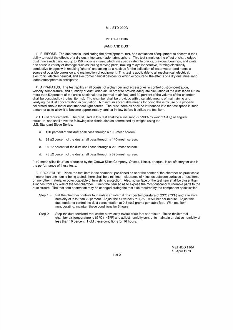
7/29/2019 TEST METHOD STANDARD ELECTRONIC AND ELECTRICAL COMPONENT PARTS
http://slidepdf.com/reader/full/test-method-standard-electronic-and-electrical-component-parts 43/191
MIL-STD-202G
METHOD 110A
SAND AND DUST
1. PURPOSE. The dust test is used during the development, test, and evaluation of equipment to ascertain theirability to resist the effects of a dry dust (fine sand) laden atmosphere. This test simulates the effect of sharp edgeddust (fine sand) particles, up to 150 microns in size, which may penetrate into cracks, crevices, bearings, and joints,and cause a variety of damage such as fouling moving parts, making relays inoperative, forming electricallyconductive bridges with resulting "shorts" and acting as a nucleus for the collection of water vapor, and hence asource of possible corrosion and malfunction of equipment. This test is applicable to all mechanical, electrical,electronic, electrochemical, and electromechanical devices for which exposure to the effects of a dry dust (fine sand)laden atmosphere is anticipated.
2. APPARATUS. The test facility shall consist of a chamber and accessories to control dust concentration,velocity, temperature, and humidity of dust-laden air. In order to provide adequate circulation of the dust laden air, nomore than 50 percent of the cross-sectional area (normal to air flow) and 30 percent of the volume of the chambershall be occupied by the test item(s). The chamber shall be provided with a suitable means of maintaining andverifying the dust concentration in circulation. A minimum acceptable means for doing this is by use of a properlycalibrated smoke meter and standard light source. The dust-laden air shall be introduced into the test space in such
a manner as to allow it to become approximately laminar in flow before it strikes the test item.
2.1 Dust requirements. The dust used in this test shall be a fine sand (97-99% by weight SiO2) of angularstructure, and shall have the following size distribution as determined by weight, using theU.S. Standard Sieve Series.
a. 100 percent of this dust shall pass through a 100-mesh screen.
b. 98 ±2 percent of the dust shall pass through a 140-mesh screen.
c. 90 ±2 percent of the dust shall pass through a 200-mesh screen.
d. 75 ±2 percent of the dust shall pass through a 325-mesh screen.
"140-mesh silica flour" as produced by the Ottawa Silica Company, Ottawa, Illinois, or equal, is satisfactory for use in
the performance of these tests.
3. PROCEDURE. Place the test item in the chamber, positioned as near the center of the chamber as practicable.If more than one item is being tested, there shall be a minimum clearance of 4 inches between surfaces of test items
or any other material or object capable of furnishing protection. Also, no surface of the test item shall be closer than4 inches from any wall of the test chamber. Orient the item so as to expose the most critical or vulnerable parts to thedust stream. The test item orientation may be changed during the test if so required by the component specification.
Step 1 - Set the chamber controls to maintain an internal chamber temperature of 23°C (73°F) and a relativehumidity of less than 22 percent. Adjust the air velocity to 1,750 ±250 feet per minute. Adjust thedust feeder to control the dust concentration at 0.3 ±0.2 grams per cubic foot. With test itemnonoperating, maintain these conditions for 6 hours.
Step 2 - Stop the dust feed and reduce the air velocity to 300 ±200 feet per minute. Raise the internalchamber air temperature to 63°C (145°F) and adjust humidity control to maintain a relative humidity ofless than 10 percent. Hold these conditions for 16 hours.
METHOD 110A16 April 1973
1 of 2
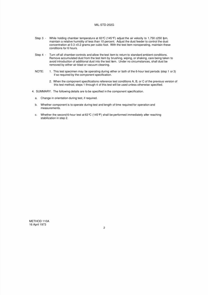
7/29/2019 TEST METHOD STANDARD ELECTRONIC AND ELECTRICAL COMPONENT PARTS
http://slidepdf.com/reader/full/test-method-standard-electronic-and-electrical-component-parts 44/191
MIL-STD-202G
Step 3 - While holding chamber temperature at 63°C (145°F) adjust the air velocity to 1,750 ±250 fpm,maintain a relative humidity of less than 10 percent. Adjust the dust feeder to control the dustconcentration at 0.3 ±0.2 grams per cubic foot. With the test item nonoperating, maintain these
conditions for 6 hours.
Step 4 - Turn off all chamber controls and allow the test item to return to standard ambient conditions.Remove accumulated dust from the test item by brushing, wiping, or shaking, care being taken toavoid introduction of additional dust into the test item. Under no circumstances, shall dust beremoved by either air blast or vacuum cleaning.
NOTE: 1. This test specimen may be operating during either or both of the 6-hour test periods (step 1 or 3)if so required by the component specification.
2. When the component specifications reference test conditions A, B, or C of the previous version ofthis test method, steps 1 through 4 of this test will be used unless otherwise specified.
4. SUMMARY. The following details are to be specified in the component specification.
a. Change in orientation during test, if required.
b. Whether component is to operate during test and length of time required for operation andmeasurements.
c. Whether the second 6-hour test at 63°C (145°F) shall be performed immediately after reachingstabilization in step 2.
METHOD 110A16 April 1973
2
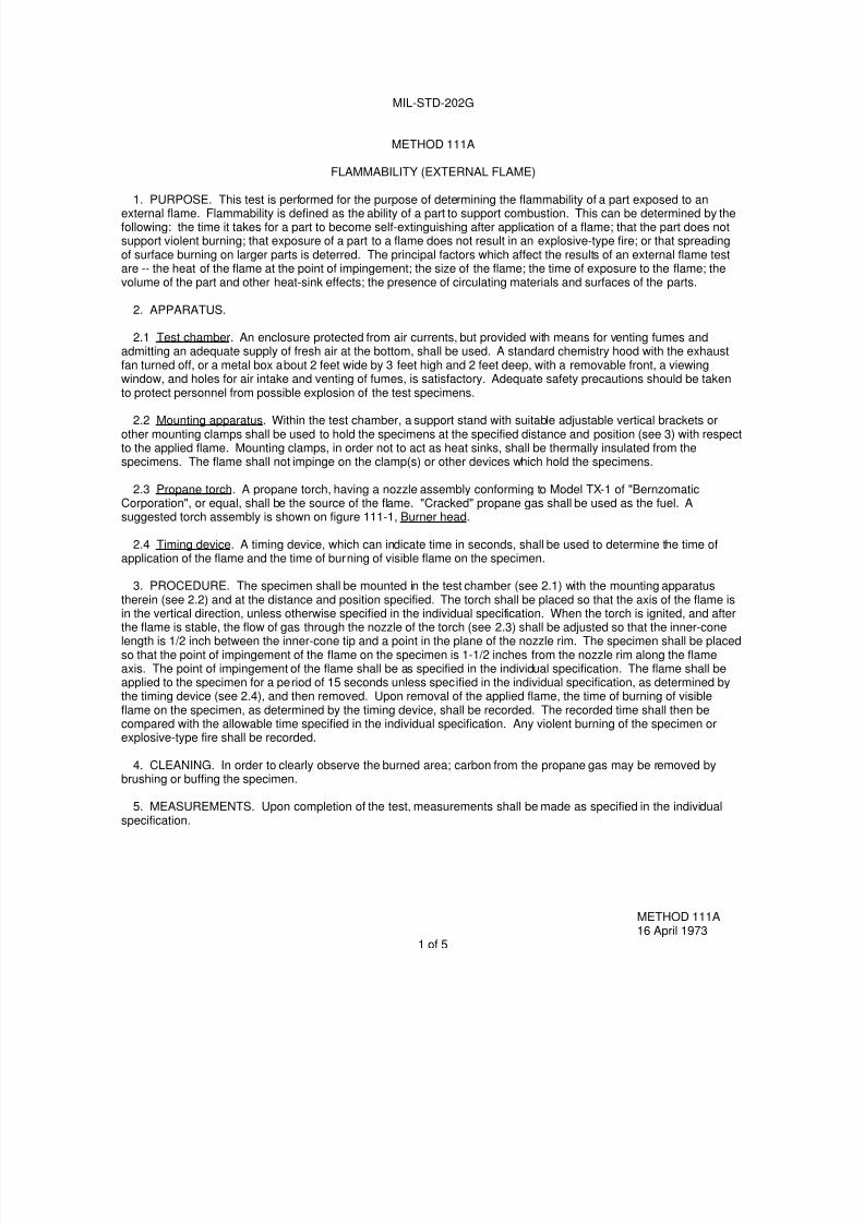
7/29/2019 TEST METHOD STANDARD ELECTRONIC AND ELECTRICAL COMPONENT PARTS
http://slidepdf.com/reader/full/test-method-standard-electronic-and-electrical-component-parts 45/191
MIL-STD-202G
METHOD 111A
FLAMMABILITY (EXTERNAL FLAME)
1. PURPOSE. This test is performed for the purpose of determining the flammability of a part exposed to anexternal flame. Flammability is defined as the ability of a part to support combustion. This can be determined by thefollowing: the time it takes for a part to become self-extinguishing after application of a flame; that the part does notsupport violent burning; that exposure of a part to a flame does not result in an explosive-type fire; or that spreadingof surface burning on larger parts is deterred. The principal factors which affect the results of an external flame testare -- the heat of the flame at the point of impingement; the size of the flame; the time of exposure to the flame; thevolume of the part and other heat-sink effects; the presence of circulating materials and surfaces of the parts.
2. APPARATUS.
2.1 Test chamber. An enclosure protected from air currents, but provided with means for venting fumes andadmitting an adequate supply of fresh air at the bottom, shall be used. A standard chemistry hood with the exhaustfan turned off, or a metal box about 2 feet wide by 3 feet high and 2 feet deep, with a removable front, a viewingwindow, and holes for air intake and venting of fumes, is satisfactory. Adequate safety precautions should be takento protect personnel from possible explosion of the test specimens.
2.2 Mounting apparatus. Within the test chamber, a support stand with suitable adjustable vertical brackets orother mounting clamps shall be used to hold the specimens at the specified distance and position (see 3) with respectto the applied flame. Mounting clamps, in order not to act as heat sinks, shall be thermally insulated from thespecimens. The flame shall not impinge on the clamp(s) or other devices which hold the specimens.
2.3 Propane torch. A propane torch, having a nozzle assembly conforming to Model TX-1 of "BernzomaticCorporation", or equal, shall be the source of the flame. "Cracked" propane gas shall be used as the fuel. Asuggested torch assembly is shown on figure 111-1, Burner head.
2.4 Timing device. A timing device, which can indicate time in seconds, shall be used to determine the time ofapplication of the flame and the time of burning of visible flame on the specimen.
3. PROCEDURE. The specimen shall be mounted in the test chamber (see 2.1) with the mounting apparatustherein (see 2.2) and at the distance and position specified. The torch shall be placed so that the axis of the flame is
in the vertical direction, unless otherwise specified in the individual specification. When the torch is ignited, and afterthe flame is stable, the flow of gas through the nozzle of the torch (see 2.3) shall be adjusted so that the inner-conelength is 1/2 inch between the inner-cone tip and a point in the plane of the nozzle rim. The specimen shall be placedso that the point of impingement of the flame on the specimen is 1-1/2 inches from the nozzle rim along the flameaxis. The point of impingement of the flame shall be as specified in the individual specification. The flame shall beapplied to the specimen for a period of 15 seconds unless specified in the individual specification, as determined bythe timing device (see 2.4), and then removed. Upon removal of the applied flame, the time of burning of visibleflame on the specimen, as determined by the timing device, shall be recorded. The recorded time shall then becompared with the allowable time specified in the individual specification. Any violent burning of the specimen orexplosive-type fire shall be recorded.
4. CLEANING. In order to clearly observe the burned area; carbon from the propane gas may be removed bybrushing or buffing the specimen.
5. MEASUREMENTS. Upon completion of the test, measurements shall be made as specified in the individualspecification.
METHOD 111A16 April 1973
1 of 5

7/29/2019 TEST METHOD STANDARD ELECTRONIC AND ELECTRICAL COMPONENT PARTS
http://slidepdf.com/reader/full/test-method-standard-electronic-and-electrical-component-parts 46/191
MIL-STD-202G
6. SUMMARY. The following details are to be specified in the individual specification:
a. Direction of axis of flame, if other than vertical (see 3).
b. Point of impingement of applied flame (see 3).
c. Time of application of flame, if other than 15 seconds (see 3).
d. Allowable time for burning of visible flame on specimen (see 3).
e. Measurements after test (see 5).
METHOD 111A16 April 1973
2

7/29/2019 TEST METHOD STANDARD ELECTRONIC AND ELECTRICAL COMPONENT PARTS
http://slidepdf.com/reader/full/test-method-standard-electronic-and-electrical-component-parts 47/191
MIL-STD-202G
Inches mm Inches mm.0004 0.01 .125 3.18.002 0.05 .127 3.23.005 0.13 .130 3.30.006 0.15 .192 4.88.010 0.25 .194 4.93.021 0.53 .250 6.35.041 1.04 .302 7.67.062 1.57 .322 8.18.082 2.08 .625 15.18.120 3.05 1.688 42.88.123 3.12
MATERIAL: BRASS
FIGURE 111-1. Burner head.
METHOD 111A16 April 1973
3
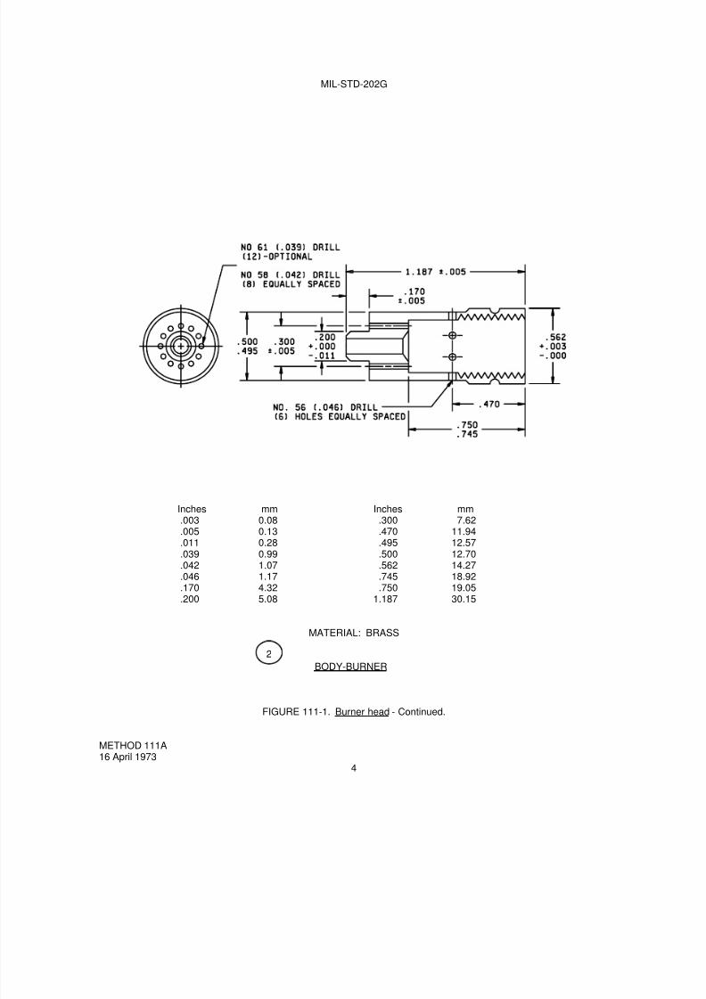
7/29/2019 TEST METHOD STANDARD ELECTRONIC AND ELECTRICAL COMPONENT PARTS
http://slidepdf.com/reader/full/test-method-standard-electronic-and-electrical-component-parts 48/191
MIL-STD-202G
Inches mm Inches mm.003 0.08 .300 7.62.005 0.13 .470 11.94.011 0.28 .495 12.57.039 0.99 .500 12.70.042 1.07 .562 14.27.046 1.17 .745 18.92.170 4.32 .750 19.05.200 5.08 1.187 30.15
MATERIAL: BRASS
BODY-BURNER
FIGURE 111-1. Burner head - Continued.
METHOD 111A16 April 1973
4
2
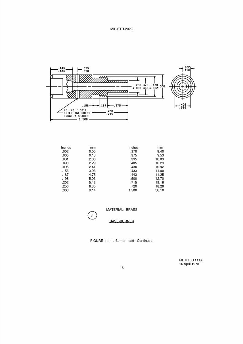
7/29/2019 TEST METHOD STANDARD ELECTRONIC AND ELECTRICAL COMPONENT PARTS
http://slidepdf.com/reader/full/test-method-standard-electronic-and-electrical-component-parts 49/191
MIL-STD-202G
Inches mm Inches mm.002 0.05 .370 9.40.005 0.13 .375 9.53.081 2.06 .395 10.03.090 2.29 .405 10.29.095 2.41 .430 10.92
.156 3.96 .433 11.00.187 4.75 .443 11.25
.198 5.03 .500 12.70
.202 5.13 .715 18.16
.250 6.35 .720 18.29
.360 9.14 1.500 38.10
MATERIAL: BRASS
BASE-BURNER
FIGURE 111-1. Burner head - Continued.
METHOD 111A16 April 1973
5
3

7/29/2019 TEST METHOD STANDARD ELECTRONIC AND ELECTRICAL COMPONENT PARTS
http://slidepdf.com/reader/full/test-method-standard-electronic-and-electrical-component-parts 50/191

7/29/2019 TEST METHOD STANDARD ELECTRONIC AND ELECTRICAL COMPONENT PARTS
http://slidepdf.com/reader/full/test-method-standard-electronic-and-electrical-component-parts 51/191
MIL-STD-202G
METHOD 112E
SEAL
1. PURPOSE. The purpose of this test method is to determine the effectiveness of the seal of a component partwhich has an internal cavity which is either evacuated or contains air or gas. A defect in any portion of the surfacearea of a sealed part can permit entrance of damaging contaminants which will reduce its effective life. This test willdetect leaks due to the use of inferior sealing materials, or to the manufacturing processes used to form the seal.The degree of completeness of the seal can be verified by testing in the "as received" condition or after submission toother environmental or physical-characteristics tests, such as thermal shock, physical shock, or vibration. This testmethod does not include the many existing versions of lesser-sensitivity seal tests now appearing in somespecifications, which verify such requirements as "water tightness", "moisture proofness", etc. In thoselesser-sensitivity seal tests, parts are submerged to various depth in water, heated water, water or alcohol with avacuum, water with a wetting agent, etc; all these tests depend on observation of bubbles as the criterion for failure.
1.1 Definitions.
a. Standard leak rate. Standard leak rate is defined as the quantity of dry air at 25°C in atmospheric cubiccentimeters flowing through a leak or multiple leak paths per second when the high-pressure side is at 1
atmosphere (760 mm Hg absolute) and the low-pressure side is at a pressure of not greater than 1 mm Hgabsolute. Standard leak rate shall be expressed in units of atmospheric cubic centimeters per second (atmcm
3 /s).
b. Measured leak rate. Measured leak rate (R1) is defined as the leak rate of a given package as measuredunder specified conditions and employing a specified test medium. Measured leak rate shall be expressedin units of atmospheric cubic centimeters per second (atm cm
3 /s). For the purpose of comparison with rates
determined by other methods of testing, the measured leak rates must be converted to equivalent standardleak rate.
c. Equivalent standard leak rate. The equivalent standard leak (L) rate of a given package, with a measuredleak rate (R1), is defined as the leak rate of the same package with the same leak geometry, which wouldexist under the standard conditions of 1.1a. The formula (does not apply to procedure IIIb) in 5.4.3.2.3represents the L/R1 ratio and gives the equivalent standard leak rate (L) of the package with a measuredleak rate (R1) where the package volume and leak test conditioning parameters influence the measured
value of (R1). The equivalent standard leak rate shall be expressed in units of atmospheric cubiccentimeters per second (atm cm
3 /s).
d. Sensitivity. (Minimum detectable leak rate). Sensitivity is the smallest leak rate that an instrument, method,or system is capable of measuring or detecting under specified conditions. To compare sensitivities of twoor more different test conditions, the sensitivity should be converted to sensitivity under standard conditionsby using the appropriate conversion factors.
e. Ambient background. For a scintillation-crystal counting station, ambient background is the oscillatoryreading obtained on the meter readout due to electrical noise plus the reading in counts per minute due tocosmic radiation that penetrates the lead shielding of the closed crystal system. This value must bedetermined just before device counting.
METHOD 112E11 October 1988
1 of 14

7/29/2019 TEST METHOD STANDARD ELECTRONIC AND ELECTRICAL COMPONENT PARTS
http://slidepdf.com/reader/full/test-method-standard-electronic-and-electrical-component-parts 52/191
MIL-STD-202G
2. TEST CONDITIONS.
2.1 Selection. There are six test conditions (A, B, C, D, E, and F) in this method. Test conditions A and B utilize
oil as a means to detect gross leaks by the observation of bubbles. Both of these tests will detect leaks of a nominalvalue of 10-5
atm cm3 /s. Test condition B is used to test parts which will not withstand the temperature required in
test condition A. Test condition C detects fine leaks by using a tracer gas and apparatus to measure a leakage rate(R1) to a nominal of 10
-8atm cm
3 /s. The apparatus can be calibrated for any leakage rate within its range. Test
condition D utilizes a fluorocarbon liquid at 125°C ±5°C (257°F ±9°F) at ambient pressure and detects gross leaks bythe observation of bubbles. This latter test condition provides an alternate gross leak test to test condition A. Testcondition E utilizes two fluorocarbon liquids; one under pressure followed by the other at 125°C ±5°C (257°F ±9°F) atroom ambient pressure and detects gross leaks by the observation of bubbles. This test condition provides ameasure of leakage rate of a nominal value of 10
-5atm cm
3 /s. Test condition F utilizes a fluorocarbon liquid and a
fluorocarbon vapor detector to detect gross leaks. Test condition F provides a measure of leakage rate of a nominalvalue of 10
-5atm cm
3 /s. Both test conditions C and F require more expensive commercial equipment and trained
personnel, but the equipment provides automatic and quantitative readings. The selection of a test condition toperform the seal test depends on the state of the art of component part manufacturing, the leakage rate which can betolerated for the desired reliability, the frequency of testing, range of test conditions, cavity size, and whether thetesting is to be on a 100 percent production or on a periodic basis. The individual specification shall specify the test
condition letter required. When test condition C is specified, the procedure number (see 5.4) and the degree ofleakage rate sensitivity required shall be included. The following is included as a sensitivity and applicability guide:
Test condition A (bubble test - mineral oil or peanut oil at 125°C ±3°C (257°F ±6°F)). Use when a nominalsensitivity of 10
-5atm cm
3 /s is sufficient.
Test condition B (bubble test - silicone oil at room ambient temperature 25°C ±2°C (77°F ±3.6°F), with a vacuumresulting in an absolute pressure of not greater than 1.5 inches of mercury (not greater than 38.1 torr). Use totest parts which cannot withstand the temperature of test condition A, and when a nominal sensitivity of 10
-5atm
cm3 /s is sufficient.
Test condition C (tracer gas test). Use when a nominal sensitivity of 10-8
atm cm3 /s is sufficient.
Procedure I - (For parts having an evacuation tube which is unsealed and is to be connected to the leakdetector for test purposes.)
Leak from outside of part to inside. Check the seal of evacuation tube by backfilling withair or gas. Then subject to procedure IIIa, IIIb, IIIc or IV.
Procedure II - (For parts having an evacuation tube which is unsealed to permit pressurizing with atracer gas.)
Leak from inside of part to outside. Check the seal of evacuation tube by backfilling withair or gas. Then subject to procedure IIIa, IIIb, IIIc, or IV.
Procedure III - (For parts which are to be tested without breaking their seals.)
Fixed method (IIIa) - Part not filled with tracer gas. Force gas into leaks, then detect itsescape. Then subject to test condition A, B or D (see 5.4.3.2.1 permitting use of water),as applicable, to check for gross leaks.
IIIb - Part not filled with tracer gas. Force radioactive gas into leaks, then use aradioactivity counter to determine gas that has entered part. Then subject to test conditionA, B, or D (see 5.4.3.2.2.4 permitting use of water), as applicable, to check for grossleaks.
METHOD 112E11 October 1988
2

7/29/2019 TEST METHOD STANDARD ELECTRONIC AND ELECTRICAL COMPONENT PARTS
http://slidepdf.com/reader/full/test-method-standard-electronic-and-electrical-component-parts 53/191
MIL-STD-202G
Flexible method (IIIc). Part not filled with tracer gas. Force gas into leaks then detect itsescape. Then subject to test condition A, B or D (see 5.4.3.2.3 permitting use of water),as applicable, to check for gross leaks.
Procedure IV - (For parts which are to be tested without breaking their seals.) Parts backfilled with tracergas as normally supplied.
Leak from inside of part to outside, then subject to test condition A, B or D (see 5.4.4permitting use of water), as applicable, to check for gross leaks.
Test condition D (gross leak bubble test - Fluorocarbon liquid at 125°C ±5°C (257°F ±9°F). Use as analternate when test condition A is specified as a gross leak test.
Test condition E (bubble test - two fluorocarbon liquids - one at pressure followed by immersion in a secondliquid at 125°C ±5°C (257°±9°F). Use when a nominal sensitivity of 10
-5atm cm
3 /s is sufficient.
Test condition F (fluorocarbon vapor detection test). Use when a nominal sensitivity of 10-5
atm cm3 /s is
sufficient.
2.2 Substitution. The individual specification should specify the lowest sensitivity test condition which is practical;a higher sensitivity test which can be calibrated shall be permitted, i.e., if a test is specified such as test condition Arequiring a sensitivity of 10
-5atm cm
3 /s, test condition C may be used since it can be calibrated to read this leakage
rate. Substitution of test condition B or C should be made to test condition A when parts are rated at a temperaturelower than 130°C (266°F). Test condition D may be substituted for test condition A.
3. TEST CONDITION A.
3.1 Materials.
3.1.1 Mineral oil or peanut oil. The oil used for the bath shall be clear mineral oil or peanut oil having a universalSaybolt viscosity of 175 to 190 seconds when tested at 38°C (100°F).
3.2 Apparatus.
3.2.1 Heated oil container. The container for the oil bath shall be of sufficient depth to immerse the uppermostportion of the enclosure or seal to be tested to a depth of 1 inch (25.4 mm) below the surface of the bath. Thecontainer shall be capable of maintaining the oil at the required temperature.
3.3 Precautions. This condition shall not be used for parts rated at a temperature lower than 130°C (266°F). Itshall not be used for parts which contain seals made of materials which will outgas due to the temperature of thebath.
3.4 Preparation of specimens. Immediately before immersion it shall be determined that the specimen is at roomambient temperature and free of any foreign (including labels) matter. If applicable, the critical side of the specimenshall be determined. The critical side is defined as the side having the greatest number of seals or length of seal.
METHOD 112E11 October 1988
3

7/29/2019 TEST METHOD STANDARD ELECTRONIC AND ELECTRICAL COMPONENT PARTS
http://slidepdf.com/reader/full/test-method-standard-electronic-and-electrical-component-parts 54/191
MIL-STD-202G
3.5 Procedure. This test consists of one immersion of the specimen or groups of specimens into a bath of clearmineral oil or peanut oil (see 3.1.1) maintained at a temperature of 125°C ±3°C (257°F ±6°F). The specimen shall beplaced in the oil bath with the critical side (or side of special interest) in a horizontal position facing up. If the
specimen has no critical side, it shall be placed in the bath with its major axis in a horizontal position. The specimenshall be completely submerged in the bath, with the uppermost portion of the enclosure or seal at a depth of 1 inch(25.4 mm), and left in that position for a minimum duration of 1 minute. The specimen shall be carefully observedduring the entire duration of the immersion for indication of a poor seal as evidenced by a continuous stream ofbubbles emanating from the specimen. After the test is completed, the specimen shall be cleaned in a suitabledegreaser and permitted to dry thoroughly before any additional tests are performed.
4. TEST CONDITION B.
4.1 Materials.
4.1.1 Silicone oil. The oil used for the bath shall be clear silicone oil having a viscosity of 20 centistokes at 25°C(77°F).
4.2 Apparatus.
4.2.1 Reduced pressure vessel. The vessel for the oil bath shall be of sufficient depth to immerse the uppermostportion of the enclosure or seal to be tested to a depth of 1 inch (25.4 mm) below the surface of the bath, over whichcan be drawn a vacuum resulting in an absolute pressure of not greater than 1.5 inches of mercury (not greater than38.1 torr).
4.2.2 Vacuum pump. The vacuum pump shall be capable of evacuating and holding a vacuum resulting in anabsolute pressure of not greater than 1.5 inches of mercury (not greater than 38.1 torr) for a minimum duration of 1minute in the reduced pressure vessel (see 4.2.1).
4.2.3 Degassing of silicone oil. The silicone oil shall be placed in the test fixture and a pressure of 1 inch (25.4mm) of mercury or less attained over the fluid for as long as is necessary to degas the fluid. Such degassing iscomplete when no further bubbling or frothing is present in the fluid. Throughout the test, components shall belowered gently in the fluid to prevent aeration of the fluid. The fluid shall not be poured from one container to anotherwithout first being degassed again before testing.
4.3 Preparation of specimens. As specified in 3.4.
4.4 Procedure. This test consists of one immersion of the specimen or group of specimens into a bath of clearsilicone oil (see 4.1.1) maintained at room ambient temperature. The specimen shall be placed in the oil bath withthe critical side (or side of special interest) in a horizontal position facing up. If the specimen has no critical side, itshall be placed in the bath with its major axis in a horizontal position. The specimen shall be completely submergedin the bath with the uppermost portion of the enclosure or seal at a depth of 1 inch (25.4 mm). A vacuum resulting inan absolute pressure of not greater than 1.5 inches of mercury (not greater than 38.1 torr) shall be drawn and heldover the bath for a minimum duration of 1 minute. The specimen shall be carefully observed during the entireduration of the immersion for indication of a poor seal as evidenced by a continuous stream of bubbles emanatingfrom the specimen. After the test is completed, the specimen shall be cleaned in a suitable degreaser and permittedto dry thoroughly before any additional tests are performed.
4.5 Precaution. This test condition should not be used either as a separate test or a gross leak test for componentparts which are to be subsequently attached to printed circuit board assemblies. Since complete removal of siliconeoil residues is difficult, the oil will be transferred unknowingly to other parts during assembly processes. Traces ofsilicone can result in poor solder wettability of component part leads, poor adhesion to sealants, and mealing of theconformal coating on the printed circuit board.
METHOD 112E11 October 1988
4
7/29/2019 TEST METHOD STANDARD ELECTRONIC AND ELECTRICAL COMPONENT PARTS
http://slidepdf.com/reader/full/test-method-standard-electronic-and-electrical-component-parts 55/191
MIL-STD-202G
5. TEST CONDITION C.
5.1 Materials.
5.1.1 Tracer gases. When performing tests in accordance with procedures I, II, and IV of this condition, tracergases, i.e., helium, argon, or other rare gas, or a mixture of a gas with nitrogen (such as 90 percent nitrogen and 10percent helium) shall be used. The tracer gas used in procedures IIIa and IIIc shall be helium. The tracer gas usedin procedure IIIb shall be the radioactive gas, krypton 85.
5.2 Apparatus. For all the procedures of this test condition, the test apparatus, exclusive of pressurizationequipment, shall be calibrated using a diffusion type calibrated standard leak at least once each working shift.
5.2.1 Mass-spectrometer-type leak detector. For procedures I, II, IIIa, IIIc, and IV of this test condition, acommercially available mass-spectrometer-type leak detector, preset to read a tracer-gas content, shall be used tomeasure the leakage rate of gas through a faulty seal. Another instrument may be used if it can be demonstrated tothe Government that the instrument, properly calibrated to read tracer-gas content, has the requiredleakage-detection sensitivity (see 2.1).
5.2.1.1 Chambers. Depending on which procedure is used (see 5.4), suitable pressure or vacuum chambers arerequired.
5.2.1.2 Pumps. Depending on which procedure is used (see 5.4), suitable pressure or vacuum pumps arerequired.
5.2.2 Radioactive-gas detection apparatus. Apparatus for procedure IIIb shall consist of:
a. Radioactive tracer gas activation console.
b. Counting equipment consisting of a scintillation crystal, photomultiplier tube, preamplifier, ratemeter, andkrypton 85 reference standards. The counting station shall be of sufficient sensitivity to determine throughthe device wall the radiation level of any krypton 85 tracer gas present within the device. The counting
station shall have a minimum sensitivity, in c/m per µCi, corresponding to a leak rate of 10-9
atm cm3 / s of
krypton 85 and shall be calibrated at least once every working shift using krypton 85 reference standards
and following the equipment manufacturer's instruction.
c. A tracer gas consisting of a mixture of krypton 85 and dry nitrogen. The concentration of krypton 85 in drynitrogen shall be no less than 100 microcuries per atmospheric cubic centimeter. This value shall bedetermined at least once each 30 days and recorded in accordance with the calibration requirements of thisstandard.
5.3 Supplementary tests. When parts to be tested are normally evacuated through a tube and are sealed in somemanner prior to delivery, procedures I and II (see 5.4.1 and 5.4.2) will require a separate verification of the seal of theevacuation tube in conjunction with this test method, using the mass-spectrometer-type leak detector (see 5.2.1).The verification may be accomplished by backfilling the specimen with air or gas at a specified pressure and thensubmitting the specimen to either procedure IIIa, IIIb, IIIc, or IV.
METHOD 112E11 October 1988
5

7/29/2019 TEST METHOD STANDARD ELECTRONIC AND ELECTRICAL COMPONENT PARTS
http://slidepdf.com/reader/full/test-method-standard-electronic-and-electrical-component-parts 56/191
MIL-STD-202G
5.4 Procedures. This test condition consists of five procedures (see 5.4.1 to 5.4.4, inclusive), the choice of whichmust be specified in the individual specification. Procedure IV is the preferred method of performing this test for partsthat are not evacuated.
5.4.1 Procedure I. The mass-spectrometer-type leak detector shall be coupled to the unsealed evacuation tube ofthe specimen, and a vacuum created within the specimen. It is extremely important that the coupling connectionsbetween the specimen and the leak detector be perfectly sealed. The specimen shall then be subjected to a gasatmosphere either by surrounding the specimen with the gas or by spraying the specimen thoroughly with a jet of thegas. If a defect exists in the specimen, an amount of gas that depends upon the size of the defect will be drawnthrough it and passed into the leak detector, which will read the leakage rate. When this portion of the procedure iscompleted, the specimen shall be filled with air or gas at a specified pressure and having a known percentage oftracer gas. The evacuation tube shall then be pinched off and sealed. After sealing, the seal of the tube shall beverified by either procedure IIIa, IIIb, IIIc or IV, if filled with tracer gas.
5.4.2 Procedure II. The mass-spectrometer-type leak detector shall be coupled to the chamber. The specimenshall be placed in the chamber, and a tube leading from the gas source and having a known percentage of tracer gasshall be connected to the unsealed evacuation tube of the specimen. It is extremely important that the couplingconnections between the specimen and the leak detector be perfectly sealed. The chamber shall then be evacuated
and the gas forced under pressure into the specimen. If a leak exists, the gas passes through the specimen into thechamber and then into the leak detector, which will read the leakage rate. If pressure cycling is required, theindividual specification shall specify the number of times that a pressure cycle shall be applied. When this portion ofthe procedure is completed, the specimen shall be filled with air or gas at a specified pressure and having a knownpercentage of tracer gas. The evacuation tube shall then be pinched off and sealed. After sealing, the seal of thetube shall be verified by either procedure IIIa, IIIb, IIIc or IV, if filled with a tracer gas.
5.4.3 Procedure III. The tests shall be conducted in accordance with procedure IIIa, or IIIc. When bomb pressurespecified exceeds the device capability, alternate pressure, exposure time and dwell time may be used provided theysatisfy the leak rate pressure, time relationships which apply and provided no less than 30 psig bomb pressure isapplied in any case.
5.4.3.1 Testing precautions.
a. These precautions are applicable to procedures IIIa, IIIb, and IIIc. To avoid spurious indications,
contaminants and surface coatings that may conceal existing leaks, and tracer gas that may be absorbed oradsorbed on the surfaces of the specimen, shall be removed. These test procedures shall not apply toorganic-coated parts.
b. Test procedure IIIa is a "fixed" method with specified conditions per table I that will insure the test sensitivitynecessary to detect the required leak rate (R1).
c. Test procedure IIIc is a "flexible" method that allows the variance of test conditions in accordance with theformula of 5.4.3.2.3 to detect the specified equivalent standard leak rate at a predetermined leak rate (R1).
5.4.3.2 General procedure. For IIIa and IIIc the completed device(s) shall be placed in a sealed chamber which isthen pressurized with a tracer gas of 100 +0, -5 percent helium for the required time and pressure. The pressureshall then be relieved and each specimen transferred to another chamber or chambers which are connected to theevacuating system and a mass-spectrometer-type leak detector. When the chamber(s) is evacuated, any tracer gaswhich was previously forced into the specimen will thus be drawn out and indicated by the leak detector as ameasured leak rate (R1). The number of devices removed from pressurization for leak testing shall be limited suchthat the test of the last device can be completed within 60 minutes for procedure IIIa or within the chosen value ofdwell time (tz) for procedure IIIc.
METHOD 112E11 October 1988
6
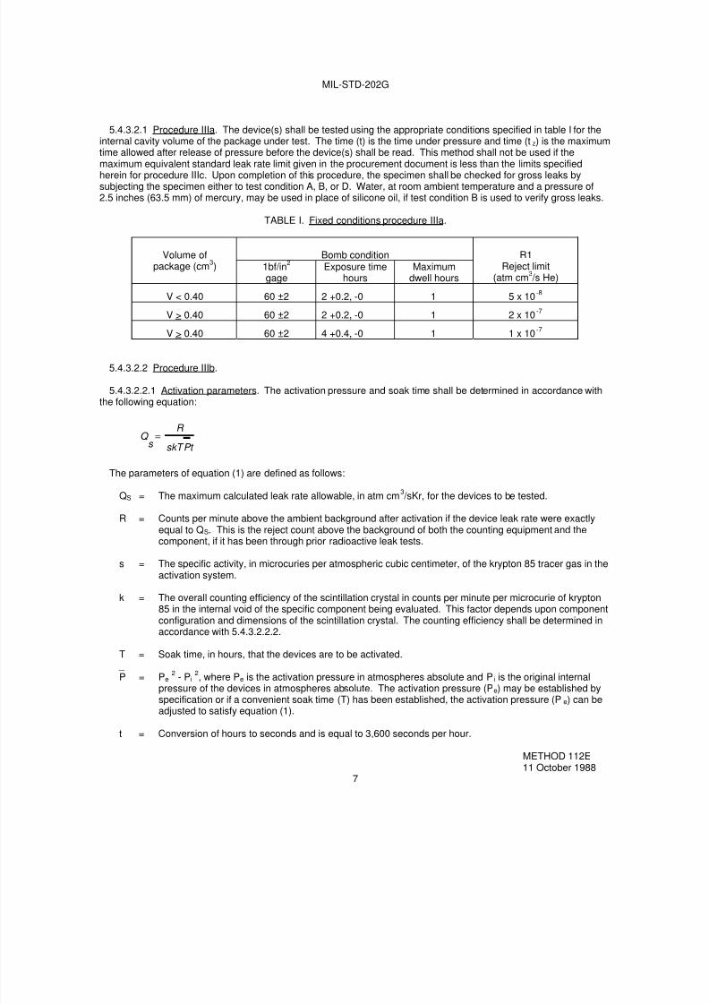
7/29/2019 TEST METHOD STANDARD ELECTRONIC AND ELECTRICAL COMPONENT PARTS
http://slidepdf.com/reader/full/test-method-standard-electronic-and-electrical-component-parts 57/191
MIL-STD-202G
5.4.3.2.1 Procedure IIIa. The device(s) shall be tested using the appropriate conditions specified in table I for theinternal cavity volume of the package under test. The time (t) is the time under pressure and time (tz) is the maximumtime allowed after release of pressure before the device(s) shall be read. This method shall not be used if the
maximum equivalent standard leak rate limit given in the procurement document is less than the limits specifiedherein for procedure IIIc. Upon completion of this procedure, the specimen shall be checked for gross leaks bysubjecting the specimen either to test condition A, B, or D. Water, at room ambient temperature and a pressure of2.5 inches (63.5 mm) of mercury, may be used in place of silicone oil, if test condition B is used to verify gross leaks.
TABLE I. Fixed conditions procedure IIIa.
Bomb conditionVolume ofpackage (cm
3) 1bf/in
2
gageExposure time
hoursMaximum
dwell hours
R1Reject limit
(atm cm3 /s He)
V < 0.40 60 ±2 2 +0.2, -0 1 5 x 10⁻⁸
V > 0.40 60 ±2 2 +0.2, -0 1 2 x 10⁻⁷
V > 0.40 60 ±2 4 +0.4, -0 1 1 x 10⁻⁷
5.4.3.2.2 Procedure IIIb.
5.4.3.2.2.1 Activation parameters. The activation pressure and soak time shall be determined in accordance withthe following equation:
t P skT
R
s Q =
The parameters of equation (1) are defined as follows:
QS
= The maximum calculated leak rate allowable, in atm cm3 /sKr, for the devices to be tested.
R = Counts per minute above the ambient background after activation if the device leak rate were exactlyequal to QS. This is the reject count above the background of both the counting equipment and thecomponent, if it has been through prior radioactive leak tests.
s = The specific activity, in microcuries per atmospheric cubic centimeter, of the krypton 85 tracer gas in theactivation system.
k = The overall counting efficiency of the scintillation crystal in counts per minute per microcurie of krypton85 in the internal void of the specific component being evaluated. This factor depends upon componentconfiguration and dimensions of the scintillation crystal. The counting efficiency shall be determined inaccordance with 5.4.3.2.2.2.
T = Soak time, in hours, that the devices are to be activated.
_ P = Pe 2
- Pi 2, where Pe is the activation pressure in atmospheres absolute and Pi is the original internal
pressure of the devices in atmospheres absolute. The activation pressure (Pe) may be established byspecification or if a convenient soak time (T) has been established, the activation pressure (Pe) can beadjusted to satisfy equation (1).
t = Conversion of hours to seconds and is equal to 3,600 seconds per hour.
METHOD 112E11 October 1988
7

7/29/2019 TEST METHOD STANDARD ELECTRONIC AND ELECTRICAL COMPONENT PARTS
http://slidepdf.com/reader/full/test-method-standard-electronic-and-electrical-component-parts 58/191
MIL-STD-202G
5.4.3.2.2.2 Determination of counting efficiency (k). The counting efficiency (k) of equation in 5.4.3.2.2.1 shall bedetermined as follows:
a. Five representative units of the device type being tested shall be tubulated and the internal void of thedevice shall be backfilled through the tubulation with a known volume and known specific activity of krypton85 tracer gas and the tubulation shall be sealed off.
b. The counts per minute shall be directly read in the shielded scintillation crystal of the counting station inwhich the devices are read. From this value, the counting efficiency, in counts per minute per microcurie,shall be calculated.
5.4.3.2.2.3 Evaluation of surface sorption. All device encapsulations consisting of glass, metal, and ceramic orcombinations thereof, including coatings and external sealants, shall be evaluated for surface sorption of krypton 85before establishing the leak test parameters. Representative samples of the questionable material shall be subjectedto the predetermined pressure and time conditions established for the device configuration as specified by5.4.3.2.2.1. The samples shall then be counted every 10 minutes, with count rate noted, until the count rate becomesasymptotic with time. (This is the point in time at which surface sorption is no longer a problem.) This time lapseshall be noted and shall determine the "wait time" specified in 5.4.3.2.2.4.
5.4.3.2.2.4 Specific procedure IIIb. The devices shall be placed in radioactive tracer gas activation tank. Theactivation chamber may be partially filled with inert material to reduce pumpdown time. The tank shall be evacuatedto 0.5 torr. The devices shall be subjected to a minimum of 2 atmospheres absolute pressure of krypton 85/drynitrogen mixture for the time necessary to satisfy the equation. Actual pressure and soak time shall be determined inaccordance with 5.4.3.2.2.1. The R value in counts per minute shall be not less than 600 above ambient background.The krypton 85/dry nitrogen gas mixture shall be evacuated to storage until 0.5 torr vacuum exists in the activation
tank. This evacuation shall be completed within 3 minutes maximum. The activation tank shall then be backfilledwith air (air wash). The devices shall then be removed from the activation tank and leak tested within 1 hour after gasexposure with a scintillation-crystal-equipped counting station. Device encapsulations that come under therequirements of 5.4.3.2.2.3 shall be exposed to ambient air for a time not less than the "wait time" determined by5.4.3.2.2.3. In no case will the time between removal from the activation chamber and test exceed 1 hour. Thisexposure shall be performed after gas exposure but before determining leak rate with the counting station. Deviceencapsulations that do not come under the requirements of 5.4.3.2.2.3 may be tested without a "wait time". (Thenumber of devices removed from pressurization for leak testing shall be limited such that the test of the last device
can be completed within 1 hour.) The actual leak rate of the component shall be calculated with the followingequation:
R
Q X MINUTE PER COUNTS NET IN READOUT ACTUALQ
S )(=
Where Q = Actual leak rate in atm cm3 /s, and QS and R are defined in 5.4.3.2.2.1.
Unless otherwise specified, devices that exhibit a leak rate equal to or greater than 1 x 10⁻⁸
atmospheric cubiccentimeters of krypton 85 per second shall be considered a failure.
Upon completion of this procedure, the specimen shall be checked for gross leaks by subjecting the specimen eitherto test condition A, B, or D. Water, at room ambient temperature and a pressure of 2.5 inches (63.5 mm) of mercury,may be used in place of silicone oil, if test condition B is used to verify gross leaks.
5.4.3.2.2.5 Personnel precautions. A Nuclear Regulatory Commission (NRC) license is necessary for possessionand use of the krypton 85 leak-est equipment. In the use of gas, code of Federal regulations Nuclear RegulatoryCommission Rules and Regulations, Title 10, Chapters 1, 20, 30, 31, and 32 should be followed and the maximumpermissible tolerance levels prescribed by the National Committee on Radiological Protection should be observed.
METHOD 112E11 October 1988
8

7/29/2019 TEST METHOD STANDARD ELECTRONIC AND ELECTRICAL COMPONENT PARTS
http://slidepdf.com/reader/full/test-method-standard-electronic-and-electrical-component-parts 59/191
MIL-STD-202G
5.4.3.2.3 Procedure IIIc. Values for bomb pressure exposure time and dwell time shall be chosen such that actualmeasured tracer gas leak rate (R1) reading obtained for the device under test (if defective) will be greater than theminimum detection sensitivity capability of the mass spectrometer. The devices shall be subjected to a minimum of 2
atmospheres absolute of helium atmosphere. If the chosen dwell time (tz) is greater than 60 minutes, graphs shall beplotted to determine an R1 value which will assure overlap with the selected gross leak test condition. The chosenvalues, in conjunction with the value of the internal volume of the device package to be tested and the maximumequivalent standard leak rate (L) limit (as shown below or as specified in the applicable procurement document), shallbe used to calculate the measured leak rate (R1) limit using the following formula:
e -
e -
- 1M
M A1/2
P
LP = R M
M A1/2
VP o
Lt 2 M
M A1/2
VP o
Lt 1
O
E 1
R1 = The measured leak rate of tracer gas (He) through the leak in atm cm3 /s He.
L = The equivalent standard leak rate in atm cm3 /s air.
PE = The pressure of exposure in atmospheres absolute.PO = The atmospheric pressure in atmospheres absolute (1 atmosphere).
MA = The molecular weight of air in grams (28.7 grams).M = The molecular weight of the tracer gas (helium) in grams (4 grams).t1 = The time of exposure to PE in seconds.t2 = The dwell time between release of pressure and leak detection in seconds.V = The internal volume of the device package cavity in cubic centimeters.
Unless otherwise specified, devices with an internal cavity volume of 0.01 cm3
or less shall be rejected if theequivalent standard leak rate (L) exceeds 5 x 10
-8atm cm
3 /s. Devices with an internal cavity volume greater than
0.01 cm3
and equal to or less than 0.4 cm3
shall be rejected if the equivalent standard leak rate (L) exceeds 1 x 10⁻⁷
atm cm
3 /s. Devices with an internal cavity volume greater than 0.4 cm
3shall be rejected if the equivalent standard
leak rate (L) exceeds 1 x 10⁻⁶
atm cm3 /s.
Upon completion of this procedure, the specimen shall be checked for gross leaks by subjecting the specimen eitherto test condition A, B, or D. Water, at room ambient temperature and a pressure of 2.5 inches of mercury, may be
used in place of silicone oil, if test condition B is used to verify gross leaks.
5.4.4 Procedure IV. The specimen, which is backfilled and sealed during production with a known percentage oftracer gas, shall be placed in a chamber connected to the mass-spectrometer-type leak detector, and the chamberevacuated. The internal pressure of the specimen shall be one atmosphere or greater. If a leak exists, the gaspasses through the specimen into the chamber and then into the leak detector which will read the leakage rate. Ifspecified, the specimen shall be perforated to determine if a gas is actually present. Upon completion of thisprocedure, the specimen shall be checked for gross leaks by subjecting the specimen either to test condition A, B, orD. Water, at room ambient temperature and a pressure of 2.5 inches (63.5 mm) of mercury, may be used in place ofsilicone oil, if test condition B is used to verify gross leaks.
METHOD 112E11 October 1988
9

7/29/2019 TEST METHOD STANDARD ELECTRONIC AND ELECTRICAL COMPONENT PARTS
http://slidepdf.com/reader/full/test-method-standard-electronic-and-electrical-component-parts 60/191
MIL-STD-202G
6. TEST CONDITION D.
6.1 Materials.
6.1.1 Fluorocarbon liquid. The fluid shall be D02, D02-TS, D03, FC-40 1/ or FC-43 2/.
6.2 Apparatus.
6.2.1 Heated fluid container. The container for the fluid shall be made of pyrex glass and shall be sufficient size tohold the test specimen in the fluid and to maintain a temperature of 125°C ±5°C (257°F ±9°F).
6.2.2 Filter. A filter shall be used which is capable of removing particles greater than 1 micron in size from thefluid.
6.2.3 Magnifier. A 3X minimum magnifier or a stereo zoom microscope shall be used for observation of bubblesemanating from the test specimens when immersed in the indicator fluid.
6.3 Precautions. The following precautions shall be observed:
a. Fluorocarbon liquids shall be filtered as specified in 6.2.2. Bulk filtering and storage is permissible. Leakindicator fluids, which have accumulated observable quantities of particulate matter during use, shall bediscarded or reclaimed by filtration for reuse. Leak detecting fluids shall not be used for more than oneeight-hour shift without being refiltered.
b. The observation container shall contain sufficient fluid to assure coverage of the test specimen to aminimum depth of two inches.
c. Illumination shall be a lighting source capable of providing at least 15,000 foot candles at the test specimenposition. The lighting source shall not require calibration but the light level shall be verified at the testspecimen position. The background behind the glass observation container should be a dull, non-reflectiveblack material.
d. The observation container should be covered at all times when not in use to minimize evaporation losses
and moisture adsorption.
e. Test specimens to be tested should be free from foreign material on the surface, including conformalcoatings and markings which may contribute to erroneous test results.
6.4 Procedure. The test specimens, mounted on specified fixtures to hold them in the fluid, shall be immersed,with the uppermost portion at the minimum depth of 2 inches below the surface of the fluid, lid downward, one at atime (or in such a configuration that a single bubble from a single specimen out of a group under observation may beclearly observed as to its occurrence and source). The fluid shall be maintained at a temperature of 125°C ±5°C(257°F ±9°F). The specimens shall be observed against a dull non-reflective black background through the magnifier(see 6.2.3) from the instant of immersion until 20 seconds after immersion. Leakers will be identified by a singlebubble or a stream of bubbles. Specimens from which a single bubble is observed is considered to be a reject.
1/ D02, D02-TS, and D03 are the registered trade mark of Ausimont (Division of Montedison).2/ Minnesota Mining Co. (3M) registered trade name.
METHOD 112E11 October 1988
10

7/29/2019 TEST METHOD STANDARD ELECTRONIC AND ELECTRICAL COMPONENT PARTS
http://slidepdf.com/reader/full/test-method-standard-electronic-and-electrical-component-parts 61/191
MIL-STD-202G
7. TEST CONDITION E.
7.1 Materials.
7.1.1 Fluorocarbon liquid. The fluids shall be D/80, FC-72 or PP-1 fluorocarbon detector fluids, and D02, D02-TS,D03, FC-40, FC-43, PP-7 or PP-9 fluorocarbon indicator fluids.
7.2 Apparatus.
7.2.1 Heated fluid container. The container for the fluid shall be made of pyrex glass and shall be of sufficient sizeto hold the test specimen in the fluid and to maintain a temperature of 125°C ±5°C (257°F ±9°F).
7.2.2 Filter. A filter shall be used which is capable of removing particles greater than 1 micron in size from thefluid.
7.2.3 Magnifier. A magnifier with a magnification in the range between 3X to 30X for observation of bubblesemanating from devices when immersed in the indicator fluid.
7.2.4 Chamber. A vacuum/pressure chamber for the evacuation and subsequent pressure bombing of device upto 75 lbf/in
2up to 10 hours.
7.2.5 Lighting source. A lighting source capable of producing at least 15,000 foot candles in air at a distance equalto that which the most distant device in the bath will be from the source.
7.2.6 Instruments. Suitable calibrated instruments to indicate the test temperature pressures and times are asspecified.
7.2.7 Fixtures. Suitable fixtures to hold the device(s) in the indicator fluid.
7.3 Precautions. The following precautions shall be observed.
a. Fluorocarbon liquids shall be filtered as specified in 7.2.2. Bulk filtering and storage is permissible. Leakindicator fluids, which have accumulated observable quantities of particulate matter during use, shall be
discarded or reclaimed by filtration for reuse. Leak detecting fluids shall not be used for more than oneeight-hour shift without being refiltered.
b. The observation container shall contain sufficient fluid to assure coverage of the test specimen to aminimum depth of two inches (50.8 mm).
c. Illumination shall be a lighting source capable of providing at least 15,000 foot candles at the test specimenposition. The lighting source shall not require calibration but the light level shall be verified at the testspecimen position. The background behind the glass observation container should be a dull, non-reflectiveblack material.
d. The observation container should be covered at all times when not in use to minimize evaporation lossesand moisture adsorption.
e. Test specimens to be tested should be free from foreign material on the surface, including conformalcoatings and markings that may contribute to erroneous test results.
f. Precautions should be taken to prevent operator injury due to package rupture or violent evolution of bombfluid when testing large packages.
METHOD 112E11 October 1988
11

7/29/2019 TEST METHOD STANDARD ELECTRONIC AND ELECTRICAL COMPONENT PARTS
http://slidepdf.com/reader/full/test-method-standard-electronic-and-electrical-component-parts 62/191
MIL-STD-202G
7.4 Procedure. The test specimens mounted on specified fixtures to hold them in the leak detecting fluid shall beinserted into the combination vacuum-pressure vessel and the applied ambient pressure shall be reduced to lessthan 5 torr for 1 hour. Then without breaking vacuum, a sufficient quantity of leak detecting fluid (see 7.1.1) to cover
the test specimens, shall be drawn into the vacuum/pressure vessel by inserting a transfer tube from thevacuum/pressure vessel into a container of leak detecting fluid and opening a valve in the tube. For test specimenswith an internal cavity volume of 0.1 cm
3or less, the pressure in the vessel shall be increased to 90 lbf/in
2and
maintained at that pressure for 3 hours minimum. For test specimens with an internal volume in excess of 0.1 cm3,
the pressure shall be increased to 50 lbf/in2
and maintained at that pressure for 3 hours minimum. Afterpressurization, the pressure shall be released from the pressure vessel and the test specimens shall be removedfrom the pressure vessel, and retained in a bath containing the leak detecting fluid. Then they shall be dried for 3 ±1minutes in air prior to immersion in the indicator fluid. The test specimens shall be immersed with the uppermostportion at a minimum depth of 2 inches (50.8 mm) below the surface of the indicator fluid, lid downward, one at a time(or in such a configuration that a single bubble from a single specimen out of a group under observation may beclearly observed as to its occurrence and source. The leak indicator fluid shall be maintained at a temperature of125°C ±5°C (257°F ±9°F). The test specimens shall be observed against a dull non-reflective black backgroundthrough the magnifier (see 7.2.3) from the instant of immersion until 20 seconds after immersion. Leaks will beidentified by a single bubble or a stream of bubbles. Specimens from which a single bubble is observed isconsidered to be a reject.
8. TEST CONDITION F.
8.1 Materials.
8.1.1 Fluorocarbon liquid. The fluid used shall be FC-84 or D/80 fluorocarbon detector fluid.
8.2 Apparatus.
8.2.1 Chamber. A vacuum/pressure chamber capable of the evacuation and subsequent pressure bombing ofdevices up to 75 psig and maintaining pressure up to 12.5 hours.
8.2.2 Filter. A filtration system capable of removing particles greater than 1 micron in size from the fluorocarbonfluid.
8.2.3 Detector. A fluorocarbon vapor detection system with a nominal sensitivity of 10-5 atm cm3 /s. The sensitivityof the detector shall be better than 14 micrograms of FC84 or D/80. The detector shall have a linear response to 280micrograms and a response time of better than 1 second.
8.2.4 Instruments. Suitable calibrated instruments to indicate that test, pressure times and temperatures are asspecified. The detection system shall be calibrated using a calibration source of fluorocarbon at least once each shiftto an accuracy of at least ±15 percent.
8.3 Precautions. The following precautions shall be observed in conducting the fluorocarbon gross leak test.
a. Fluorocarbons shall be filtered through a filter system capable of removing particles greater than 1micrometer prior to use. Bulk filtering and storage is permissible. Liquid that has accumulated observablequantities of particulate matter during use shall be discarded or reclaimed by filtration for re-use.Precautions shall be taken to prevent contamination.
b. Precautions should be taken to prevent operator injury due to package rupture or violent evolution of bombfluid when testing large packages.
METHOD 112E11 October 1988
12

7/29/2019 TEST METHOD STANDARD ELECTRONIC AND ELECTRICAL COMPONENT PARTS
http://slidepdf.com/reader/full/test-method-standard-electronic-and-electrical-component-parts 63/191
MIL-STD-202G
8.4 Procedure. The devices shall be placed in a vacuum/pressure chamber and the pressure reduced to 5 torr orlower and maintained for 30 minutes minimum. A sufficient amount of FC-84 or D/80 detector fluid shall be admittedto the pressure chamber to completely cover the devices. The fluid shall be admitted after the 30 minute minimum
vacuum period but before breaking the vacuum. The devices shall then be pressurized in accordance with table II.Upon completion of the pressurization period, the pressure shall be released and the devices removed from thepressure chamber without being removed from the detector fluid for more than 20 seconds. When the devices areremoved from the fluid for testing, they shall be air dried for a minimum of 20 seconds and a maximum of 5 minutesprior to the test cycle. The devices shall then be tested with a fluorocarbon vapor detector in accordance with thesystem operating instructions and as follows. Devices shall be admitted to the purge chamber and purged (heated toremove any remaining surface fluorocarbon and to initiate vaporization of any internal fluorocarbon fluid). Purge timeshall be in accordance with table III. Test time shall commence immediately after purge either in the same chamber(single chamber system) or an adjoining test chamber (dual chamber system). Test time shall be a minimum of 3.5seconds (unless the device is rejected earlier) with the fluorocarbon vapor detector purge and test chambers at atemperature of 125°C ±5°C or 2.5 seconds minimum with the purge and test chambers at 150°C ±5°C. During testtime, the amount of fluorocarbon outgassing is measured and the total integrated value is compared to the alarmlevel.
NOTE: Air dry, purge, and test time limits for each device shall be complied with in all cases, whether the device is
handled individually or in plastic or metal tubes.
8.4.1 Failure criteria. A device shall be rejected if the detector instrumentation indicates more than 280micrograms of fluorocarbon gas.
TABLE II. Test pressure and duration for condition F.
Test pressure Duration
75 psig .5 hr60 psig 1.0 hr30 psig 2.5 hr15 psig 12.5 hr
TABLE III. Purge time for condition F.
Package with internalfree volume (cm
3)
Purge time 1/ (seconds)
≤ 0.01 3 1/3-5
>0.01 ≤0.10 6-9
>0.10 8 2/3-13
1/ With purge chamber at 150°C, minimum and maximumpurge times should be reduced by 1/3.
NOTE: If necessary, due to device construction or materials, maximum purge time can be determined by cycling adevice with a 0.02 to 0.05 inch diameter hole and measuring the maximum time that can be used without permittingthe device to escape detection during the test cycle.
METHOD 112E11 October 1988
13

7/29/2019 TEST METHOD STANDARD ELECTRONIC AND ELECTRICAL COMPONENT PARTS
http://slidepdf.com/reader/full/test-method-standard-electronic-and-electrical-component-parts 64/191
MIL-STD-202G
9. Measurements. Upon completion of the test, measurements shall be made as specified.
10. Summary. The following details are to be specified in the individual specification.
a. Test condition letter (see 2.1).
(1) For test condition C.
(a) Procedure number and accept and reject leak rate.
(b) Backfilling pressure when verification of seal is required (see 5.3, 5.4.1 and 5.4.2).
(c) Number of pressure cycles if applicable (see 5.4.2).
(d) For procedure IV.
1. Reduced pressure of the chamber and duration of pressurization (see 5.4.4).
2. Whether perforation of specimen is required (see 5.4.4).
(e) For procedures III and IV.
1. Applicable gross leak conditions.
(2) For test conditions D and E.
(a) Test mounting fixtures (see 6.4 and 7.4).
1. Measurements after test (see 9).
METHOD 112E11 October 1988
14

7/29/2019 TEST METHOD STANDARD ELECTRONIC AND ELECTRICAL COMPONENT PARTS
http://slidepdf.com/reader/full/test-method-standard-electronic-and-electrical-component-parts 65/191
MIL-STD-202G
CLASS 200
PHYSICAL-CHARACTERISTICS TESTS

7/29/2019 TEST METHOD STANDARD ELECTRONIC AND ELECTRICAL COMPONENT PARTS
http://slidepdf.com/reader/full/test-method-standard-electronic-and-electrical-component-parts 66/191

7/29/2019 TEST METHOD STANDARD ELECTRONIC AND ELECTRICAL COMPONENT PARTS
http://slidepdf.com/reader/full/test-method-standard-electronic-and-electrical-component-parts 67/191
MIL-STD-202G
METHOD 201A
VIBRATION
1. PURPOSE. The vibration test is used to determine the effects on component parts of vibration within thepredominant frequency ranges and magnitudes that may be encountered during field service. Most vibrationencountered in field service is not of a simple harmonic nature, but tests based on vibrations of this type have provedsatisfactory for determining critical frequencies, modes of vibration and other data necessary for planning protectivesteps against the effects of undue vibration. Vibration, by causing loosening of parts or relative motion between partsin the specimen, can produce objectionable operating characteristics, noise, wear, and physical distortion, and oftenresults in fatigue and failure of mechanical parts.
2. PROCEDURE. Prior to vibration, the specified tests or measurements shall be made. The specimens shall bemounted as specified using suitable mounting apparatus to assure that mounting is free from resonances over thetest frequency range. The specimens shall be subjected to a simple harmonic motion having an amplitude of 0.03inch (0.06 inch maximum total excursion), the frequency being varied uniformly between the approximate limits of 10and 55 hertz (Hz). The entire frequency range, from 10 to 55 Hz and return to 10 Hz, shall be traversed inapproximately 1 minute. Unless otherwise specified, this motion shall be applied for a period of 2 hours in each of 3mutually perpendicular directions (total of 6 hours).1 / If applicable, this test shall be made under electrical-load
conditions.
3. MEASUREMENTS. The specified measurements shall be made during and after vibration.
4. SUMMARY. The following details are to be specified in the individual specification:
a. Tests and measurements prior to vibration (see 2).
b. Method of mounting (see 2).
c. Duration of vibration, if other than that specified (see 2).
d. Direction of motion, if other than that specified (see 2).
e. Electrical-load conditions, if applicable (see 2).
f. Tests and measurements during and after vibration (see 3).
1/ In the previous issue of this method, test conditions A and B referred to a length of test of 5 hours and 2-1/2hours, respectively.
METHOD 201A24 October 1956
1 of 1

7/29/2019 TEST METHOD STANDARD ELECTRONIC AND ELECTRICAL COMPONENT PARTS
http://slidepdf.com/reader/full/test-method-standard-electronic-and-electrical-component-parts 68/191
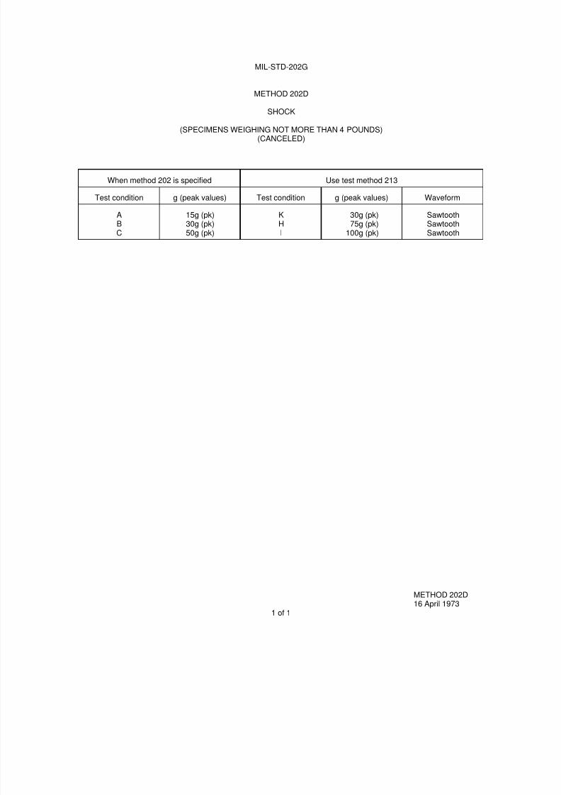
7/29/2019 TEST METHOD STANDARD ELECTRONIC AND ELECTRICAL COMPONENT PARTS
http://slidepdf.com/reader/full/test-method-standard-electronic-and-electrical-component-parts 69/191
MIL-STD-202G
METHOD 202D
SHOCK
(SPECIMENS WEIGHING NOT MORE THAN 4 POUNDS)(CANCELED)
When method 202 is specified Use test method 213
Test condition g (peak values) Test condition g (peak values) Waveform
ABC
15g (pk)30g (pk)50g (pk)
KHI
30g (pk)75g (pk)
100g (pk)
SawtoothSawtoothSawtooth
METHOD 202D16 April 1973
1 of 1

7/29/2019 TEST METHOD STANDARD ELECTRONIC AND ELECTRICAL COMPONENT PARTS
http://slidepdf.com/reader/full/test-method-standard-electronic-and-electrical-component-parts 70/191

7/29/2019 TEST METHOD STANDARD ELECTRONIC AND ELECTRICAL COMPONENT PARTS
http://slidepdf.com/reader/full/test-method-standard-electronic-and-electrical-component-parts 71/191
MIL-STD-202G
METHOD 203C
RANDOM DROP
1. PURPOSE. The random-drop test is used to determine the effects on component parts of random, repeatedimpact due to handling, shipping, and other field service conditions. The test is an accelerated test designed toindicate structural and mechanical weaknesses of types not necessarily detected in shock and vibration tests.
2. APPARATUS. The random-drop test machine consists of an assembly of either two or four steel cages asshown on figure 203-2, with provisions for rotation about a common axis. The interior of each cage shall be as shownon figure 203-3. A typical 4-cage machine is shown on figure 203-1. Steel sleeves as shown on figure 203-4 shall beused to mount the specimen.
3. PROCEDURE. The specimen shall be rigidly mounted by the normal mounting means in the steel sleeve sothat no part of the specimen, including terminals or external hardware of the component, will extend beyond thesleeve. When necessary, a suitable adapter may be used within the sleeve. End caps shall not be used on thesleeves. Through bolts may be employed as needed to mount the specimens in the sleeve. Only one sleeve shall beplaced in each cage during test. The number of specimens mounted in each sleeve shall be limited only by theavailable space. Specimens shall be subjected to the random-drop test for a period of 45 minutes at a speed of four
to six (4 – 6) revolutions per minute. The machine shall be rotated in the direction shown on figure 203-3.
4. MEASUREMENTS. Upon completion of the test, measurements shall be made as specified in the individualspecification.
5. SUMMARY. The following detail shall be specified in the individual specification:
a. Measurements after test (see 4).
METHOD 203C 8 February 2002
1 of 6
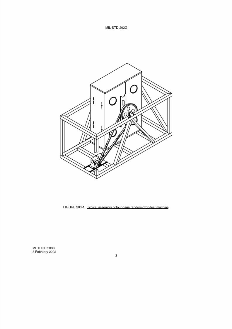
7/29/2019 TEST METHOD STANDARD ELECTRONIC AND ELECTRICAL COMPONENT PARTS
http://slidepdf.com/reader/full/test-method-standard-electronic-and-electrical-component-parts 72/191
MIL-STD-202G
FIGURE 203-1. Typical assembly of four-cage random-drop-test machine.
METHOD 203C8 February 2002
2
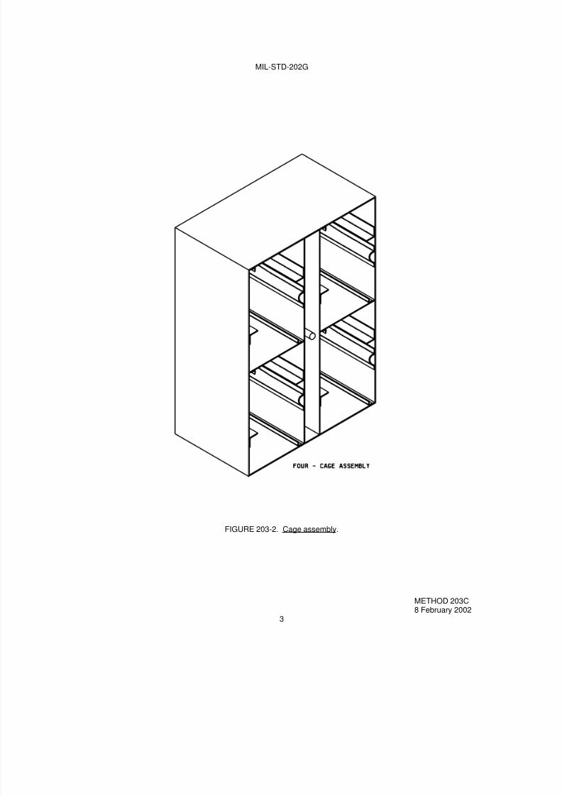
7/29/2019 TEST METHOD STANDARD ELECTRONIC AND ELECTRICAL COMPONENT PARTS
http://slidepdf.com/reader/full/test-method-standard-electronic-and-electrical-component-parts 73/191
MIL-STD-202G
FIGURE 203-2. Cage assembly.
METHOD 203C8 February 2002
3

7/29/2019 TEST METHOD STANDARD ELECTRONIC AND ELECTRICAL COMPONENT PARTS
http://slidepdf.com/reader/full/test-method-standard-electronic-and-electrical-component-parts 74/191
MIL-STD-202G
FIGURE 203-2. Cage assembly - Continued.
METHOD 203C8 February 2002
4

7/29/2019 TEST METHOD STANDARD ELECTRONIC AND ELECTRICAL COMPONENT PARTS
http://slidepdf.com/reader/full/test-method-standard-electronic-and-electrical-component-parts 75/191
MIL-STD-202G
CL
Inches mm Inches mm Inches mm.94 23.83 12.00 304.80 20.00 508.00
2.00 50.80 12.91 327.91 20.16 512.063.00 76.20 15.25 387.35 30.50 774.703.06 77.72
NOTES:1. Unless otherwise specified, tolerances are ±.06 (1.52 mm) on decimals and ±0° 30' on angles.2. Material for end and side panels shall be steel .0747 (1.90 mm) nominal thickness.3. Material for shelves and deflectors shall be steel .083 (2.11 mm) nominal thickness.
FIGURE 203-3. Cage (interior).
METHOD 203C8 February 2002
5

7/29/2019 TEST METHOD STANDARD ELECTRONIC AND ELECTRICAL COMPONENT PARTS
http://slidepdf.com/reader/full/test-method-standard-electronic-and-electrical-component-parts 76/191
MIL-STD-202G
Dimensions
A B ±.06 (1.52) C ±.06 (1.52) D E (Rad) F ±.06 (1.52)
3.870(98.30)
4.03(102.36)
3.75(95.25)
2.220(56.39)
7/ 1.220(30.99)
3.370(85.60)
3.870(98.30)
4.03(102.36)
3.75(95.25)
2.820(71.63)
7/ 1.580(40.13)
3.370(85.60)
4.870(123.70)
5.03(127.76)
4.75(120.65)
3.820(97.03)
8/ 2.062(52.37)
4.370(111.00)
NOTES:1. Metric equivalents are in parentheses.2. Unless otherwise specified, tolerances are ±.005 (0.13 mm) for three place decimals, and ±.02 (0.51 mm) for
two place decimals.3. Material for sleeve and reinforcing rings shall be carbon steel, condition CWSR, grade MT1015 or 1015,
conforming to ASTM A 519-96.4. Material shall be hot-rolled steel strip, annealed condition, annealed finish, conforming to QQ-S-698.
5. Silver solder all around. Silver solder shall conform to class 1 of QQ-B-654.6. End of cylinder to be spun-over after insertion of reinforcing ring.7. Radius of 3 holes equally spaced.8. Radius of 6 holes equally spaced.
FIGURE 203-4. Sleeve.
METHOD 203C8 February 2002
6
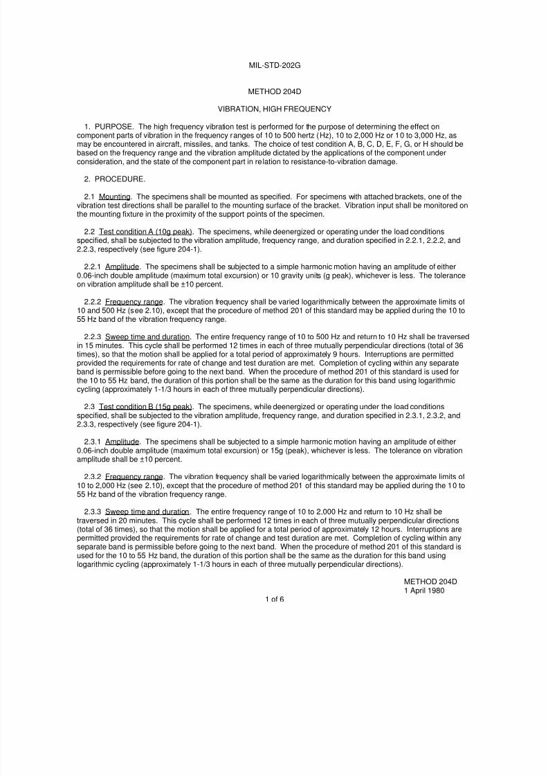
7/29/2019 TEST METHOD STANDARD ELECTRONIC AND ELECTRICAL COMPONENT PARTS
http://slidepdf.com/reader/full/test-method-standard-electronic-and-electrical-component-parts 77/191
MIL-STD-202G
METHOD 204D
VIBRATION, HIGH FREQUENCY
1. PURPOSE. The high frequency vibration test is performed for the purpose of determining the effect oncomponent parts of vibration in the frequency ranges of 10 to 500 hertz (Hz), 10 to 2,000 Hz or 10 to 3,000 Hz, asmay be encountered in aircraft, missiles, and tanks. The choice of test condition A, B, C, D, E, F, G, or H should bebased on the frequency range and the vibration amplitude dictated by the applications of the component underconsideration, and the state of the component part in relation to resistance-to-vibration damage.
2. PROCEDURE.
2.1 Mounting. The specimens shall be mounted as specified. For specimens with attached brackets, one of thevibration test directions shall be parallel to the mounting surface of the bracket. Vibration input shall be monitored onthe mounting fixture in the proximity of the support points of the specimen.
2.2 Test condition A (10g peak). The specimens, while deenergized or operating under the load conditionsspecified, shall be subjected to the vibration amplitude, frequency range, and duration specified in 2.2.1, 2.2.2, and2.2.3, respectively (see figure 204-1).
2.2.1 Amplitude. The specimens shall be subjected to a simple harmonic motion having an amplitude of either0.06-inch double amplitude (maximum total excursion) or 10 gravity units (g peak), whichever is less. The toleranceon vibration amplitude shall be ±10 percent.
2.2.2 Frequency range. The vibration frequency shall be varied logarithmically between the approximate limits of10 and 500 Hz (see 2.10), except that the procedure of method 201 of this standard may be applied during the 10 to55 Hz band of the vibration frequency range.
2.2.3 Sweep time and duration. The entire frequency range of 10 to 500 Hz and return to 10 Hz shall be traversedin 15 minutes. This cycle shall be performed 12 times in each of three mutually perpendicular directions (total of 36times), so that the motion shall be applied for a total period of approximately 9 hours. Interruptions are permittedprovided the requirements for rate of change and test duration are met. Completion of cycling within any separateband is permissible before going to the next band. When the procedure of method 201 of this standard is used forthe 10 to 55 Hz band, the duration of this portion shall be the same as the duration for this band using logarithmic
cycling (approximately 1-1/3 hours in each of three mutually perpendicular directions).
2.3 Test condition B (15g peak). The specimens, while deenergized or operating under the load conditionsspecified, shall be subjected to the vibration amplitude, frequency range, and duration specified in 2.3.1, 2.3.2, and2.3.3, respectively (see figure 204-1).
2.3.1 Amplitude. The specimens shall be subjected to a simple harmonic motion having an amplitude of either0.06-inch double amplitude (maximum total excursion) or 15g (peak), whichever is less. The tolerance on vibrationamplitude shall be ±10 percent.
2.3.2 Frequency range. The vibration frequency shall be varied logarithmically between the approximate limits of10 to 2,000 Hz (see 2.10), except that the procedure of method 201 of this standard may be applied during the 10 to55 Hz band of the vibration frequency range.
2.3.3 Sweep time and duration. The entire frequency range of 10 to 2,000 Hz and return to 10 Hz shall betraversed in 20 minutes. This cycle shall be performed 12 times in each of three mutually perpendicular directions(total of 36 times), so that the motion shall be applied for a total period of approximately 12 hours. Interruptions arepermitted provided the requirements for rate of change and test duration are met. Completion of cycling within anyseparate band is permissible before going to the next band. When the procedure of method 201 of this standard isused for the 10 to 55 Hz band, the duration of this portion shall be the same as the duration for this band usinglogarithmic cycling (approximately 1-1/3 hours in each of three mutually perpendicular directions).
METHOD 204D1 April 1980
1 of 6

7/29/2019 TEST METHOD STANDARD ELECTRONIC AND ELECTRICAL COMPONENT PARTS
http://slidepdf.com/reader/full/test-method-standard-electronic-and-electrical-component-parts 78/191
MIL-STD-202G
G = .0512f2DA (f = frequency in hertz, DA = double amplitude in inches.)
FIGURE 204-1. Vibration-test curves.
METHOD 204D1 April 1980
2

7/29/2019 TEST METHOD STANDARD ELECTRONIC AND ELECTRICAL COMPONENT PARTS
http://slidepdf.com/reader/full/test-method-standard-electronic-and-electrical-component-parts 79/191
MIL-STD-202G
2.4 Test condition C (10g peak). The specimens, while de-energized or operating under the load conditionsspecified, shall be subjected to the vibration amplitude and frequency range shown on figure 204-1. The tolerance onvibration amplitude shall be ±10 percent.
2.4.1 Part 1. The specimens shall be tested in accordance with method 201 of this standard for 6 hours; 2 hours ineach of three mutually perpendicular directions.
2.4.2 Part 2. The specimens shall be subjected to a simple harmonic motion having an amplitude varied tomaintain a constant peak acceleration of 10g (peak), the frequency being varied logarithmically between theapproximate limits of 55 and 2,000 Hz (see 2.10). The entire frequency range of 55 to 2,000 Hz (no return sweep)shall be traversed in 35 ±5 minutes, except that in the vicinity of what appears to be resonance, and in order tofacilitate the establishment of a resonant frequency, the above rate may be decreased. If resonance is detected,specimens shall be vibrated for 5 minutes at each critical resonant frequency observed. This procedure shall beperformed in each of three mutually perpendicular directions. Interruptions are permitted provided the requirementsfor rate of change and test duration are met.
2.4.3 Resonance. A critical resonant frequency is that frequency at which any point on the specimen is observedto have a maximum amplitude more than twice that of the support points. When specified, resonant frequencies shall
be determined either by monitoring parameters such as contact opening, or by use of resonance-detectinginstrumentation.
2.5 Test condition D (20g peak). The specimens, while de-energized or operating under the load conditionsspecified, shall be subjected to the vibration amplitude, frequency, range, and duration specified in 2.5.1, 2.5.2, and2.5.3, respectively (see fig. 204-1).
2.5.1 Amplitude. The specimens shall be subjected to a simple harmonic motion having an amplitude of either0.06-inch double amplitude (maximum total excursion) or 20g (peak), whichever is less. The tolerance on vibrationamplitude shall be ±10 percent.
2.5.2 Frequency range. The vibration frequency shall be varied logarithmically between the approximate limits of10 to 2,000 Hz (see 2.10), except that the procedure of method 201 of this standard may be applied during the 10 to55 Hz band of the vibration frequency range.
2.5.3 Sweep time and duration. The entire frequency range of 10 to 2,000 Hz and return to 10 Hz shall betraversed in 20 minutes. This cycle shall be performed 12 times in each of three mutually perpendicular directions(total of 36 times), so that the motion shall be applied for a total period of approximately 12 hours. Interruptions arepermitted provided the requirements for rate of change and test duration are met. Completion of cycling within anyseparate band is permissible before going to the next band. When the procedure of method 201 of this standard isused for the 10 to 55 Hz band, the duration of this portion shall be the same as the duration for this band usinglogarithmic cycling (approximately 1-1/3 hours in each of three mutually perpendicular directions).
2.6 Test condition E (50g peak). The specimens, while de-energized or operating under the load conditionsspecified, shall be subjected to the vibration amplitude, frequency, range, and duration specified in 2.6.1, 2.6.2, and2.6.3, respectively (see figure 204-1).
2.6.1 Amplitude. The specimens shall be subjected to a simple harmonic motion having an amplitude of either0.06-inch double amplitude (maximum total excursion) or 50g (peak), whichever is less. The tolerance on vibrationamplitude shall be ±10 percent.
2.6.2 Frequency range. The vibration frequency shall be varied logarithmically between the approximate limits of10 and 2,000 Hz (see 2.10), except that the procedure of method 201 of this standard may be applied during the 10to 55 Hz band of the vibration frequency range.
METHOD 204D1 April 1980
3

7/29/2019 TEST METHOD STANDARD ELECTRONIC AND ELECTRICAL COMPONENT PARTS
http://slidepdf.com/reader/full/test-method-standard-electronic-and-electrical-component-parts 80/191
MIL-STD-202G
2.6.3 Sweep time and duration. The entire frequency range of 10 to 2,000 Hz and return to 10 Hz shall betraversed in 20 minutes. This cycle shall be performed 12 times in each of three mutually perpendicular directions(total of 36 times), so that the motion shall be applied for a total period of approximately 12 hours. Interruptions are
permitted provided the requirements for rate of change and test duration are met. Completion of cycling within anyseparate band is permissible before going to the next band. When the procedure of method 201 of this standard isused for the 10 to 55 Hz band, the duration of this portion shall be the same as the duration for this band usinglogarithmic cycling (approximately 1-1/3 hours in each of three mutually perpendicular directions).
2.7 Test condition F (20g peak). The specimens, while de-energized or operating under the load conditionsspecified, shall be subjected to the vibration amplitude, frequency range, and duration specified in 2.7.1, 2.7.2, and2.7.3, respectively (see figure 204-1).
2.7.1 Amplitude. The specimens shall be subjected to a simple harmonic motion having an amplitude of either0.06-inch double amplitude (maximum total excursion) or 20g (peak), whichever is less. The tolerance on vibrationamplitude shall be ±10 percent.
2.7.2 Frequency range. The vibration frequency shall be varied logarithmically between the limits of 10 and 3,000Hz (see 2.10), except that the procedure of method 201 of this standard may be applied during the 10 to 55 Hz band
of the vibration frequency range.
2.7.3 Sweep time and duration. The entire frequency range of 10 to 3,000 Hz and return to 10 Hz shall betraversed in 20 minutes. This cycle shall be performed 12 times in each of three mutually perpendicular directions(total of 36 times), so that the motion shall be applied for a total period of approximately 12 hours. Interruptions arepermitted provided the requirements for rate of change and test duration are met. Completion of cycling within anyseparate band is permissible before going to the next band. When the procedure of method 201 of this standard isused for the 10 to 55 Hz band, the duration of this portion shall be the same as the duration for this band usinglogarithmic cycling (approximately) 1-1/3 hours in each of three mutually perpendicular directions.
2.8 Test condition G (30g peak). The specimens, while deenergized or operating under the load conditionsspecified, shall be subjected to the vibration amplitude, frequency range, and duration specified in 2.8.1, 2.8.2, and2.8.3, respectively (see figure 204-1).
2.8.1 Amplitude. The specimens shall be subjected to a simple harmonic motion having an amplitude of either
0.06-inch double amplitude (maximum total excursion) or 30g (peak), whichever is less. The tolerance on vibrationamplitude shall be ±10 percent.
2.8.2 Frequency range. The vibration frequency shall be varied logarithmically between the limits of 10 and 2,000Hz (see 2.10), except that the procedure of method 201 of this standard may be applied during the 10 to 55 Hz bandof the vibration frequency range.
2.8.3 Sweep time and duration. The entire frequency range of 10 to 2,000 Hz and return to 10 Hz shall betraversed in 20 minutes. This cycle shall be performed 12 times in each of three mutually perpendicular directions(total of 36 times), so that the motion shall be applied for a total period of approximately 12 hours. Interruptions arepermitted provided the requirements for rate of change and test duration are met. Completion of cycling within anyseparate band is permissible before going to the next band. When the procedure of method 201 of this standard isused for the 10 to 55 Hz band, the duration of this portion shall be the same as the duration for this band usinglogarithmic cycling (approximately) 1-1/3 hours in each of three mutually perpendicular directions.
METHOD 204D1 April 1980
4

7/29/2019 TEST METHOD STANDARD ELECTRONIC AND ELECTRICAL COMPONENT PARTS
http://slidepdf.com/reader/full/test-method-standard-electronic-and-electrical-component-parts 81/191
MIL-STD-202G
2.9 Test condition H (80g peak). The specimens, while de-energized or operating under the load conditionsspecified, shall be subjected to the vibration amplitude, frequency range, and duration specified in 2.9.1, 2.9.2, and2.9.3, respectively (see figure 204-1).
2.9.1 Amplitude. The specimens shall be subjected to a simple harmonic motion having a constant amplitude ofeither 0.06-inch double amplitude (maximum total excursion) or 80g (peak), whichever is less. The tolerance onvibration amplitude shall be ±10 percent.
2.9.2 Frequency range. The vibration frequency shall be varied logarithmically between the limits of 10 and 2,000Hz (see 2.10), except that the procedure of method 201 of this standard may be applied during the 10 to 55 Hz bandof the vibration frequency range.
2.9.3 Sweep time and duration. The entire frequency range of 10 to 2,000 Hz and return to 10 Hz shall betraversed in 20 minutes. This cycle shall be performed 12 times in each of three mutually perpendicular directions(total of 36 times), so that the motion shall be applied for a total period of approximately 12 hours. Interruptions arepermitted provided the requirements for rate of change and test duration are met. Completion of cycling within anyseparate band is permissible before going to the next band. When the procedure of method 201 of this standard isused for the 10 to 55 Hz band, the duration of this portion shall be the same as the duration for this band using
logarithmic cycling (approximately) 1-1/3 hours in each of three mutually perpendicular directions.
2.10 Alternate procedure for use of linear in place of logarithmic change of frequency. Linear rate of change offrequency is permissible under the following conditions:
a. The frequency range above 55 Hz shall be subdivided into not less than three bands. The ratio of themaximum frequency to the minimum frequency in each band shall be not less than two.
b. The rate of change of frequency in hertz per minute (Hz/min) shall be constant for any one band.
c. The ratios of the rate of change of frequency of each band to the maximum frequency of that band shall beapproximately equal.
2.10.1 Example of alternate procedure. As an example of the computation of rates of change, assume that thefrequency spectrum has been divided into three bands, 55 to 125 Hz, 125 to 500 Hz, and 500 to 2,000 Hz, in
accordance with 2.10a. Let the (constant) ratio of rate of frequency change in Hz/min, to maximum frequency in Hzbe k for each band. Then the rates of change for the three bands will be 125k, 500k, and 2,000k, respectively. Thetimes, in minutes, to traverse the three frequency bands will therefore be respectively:
k k k 000,2
5002000,
500
125500,
55
55125 −−−
Since the minimum total sweep time is 30 minutes,
k k k 000,2
500,1
500
375
125
7030 ++=
from which: k = 0.0687
The required maximum constant rates of frequency change for the three bands are therefore 8.54, 34.4, and 136.6Hz/min, respectively. The minimum times of traverse of the bands are 8.2, 10.9, and 10.9 minutes, respectively.
METHOD 204D1 April 1980
5

7/29/2019 TEST METHOD STANDARD ELECTRONIC AND ELECTRICAL COMPONENT PARTS
http://slidepdf.com/reader/full/test-method-standard-electronic-and-electrical-component-parts 82/191
MIL-STD-202G
3. MEASUREMENTS. Measurements shall be made as specified.
4. SUMMARY. The following details are to be specified in the individual specification:
a. Mounting of specimens (see 2.1).
b. Electrical-load conditions, if applicable (see 2.2, 2.3, 2.4, 2.5, 2.6, 2.7, 2.8, and 2.9).
c. Test condition letter (see figure 204-1).
d. Method of determining resonance, if applicable (see 2.4.3).
e. Measurements (see 3).
METHOD 204D1 April 1980
6

7/29/2019 TEST METHOD STANDARD ELECTRONIC AND ELECTRICAL COMPONENT PARTS
http://slidepdf.com/reader/full/test-method-standard-electronic-and-electrical-component-parts 83/191
MIL-STD-202G
METHOD 205E
SHOCK, MEDIUM IMPACT(CANCELED)
When method 205 is specified Use test method 213
Test condition g (peak values) Test condition g (peak values) Waveform
ABC
15g (pk)30g (pk)50g (pk)
KHI
30g (pk)75g (pk)100g (pk)
SawtoothSawtoothSawtooth
METHOD 205E16 April 1973
1 of 1

7/29/2019 TEST METHOD STANDARD ELECTRONIC AND ELECTRICAL COMPONENT PARTS
http://slidepdf.com/reader/full/test-method-standard-electronic-and-electrical-component-parts 84/191
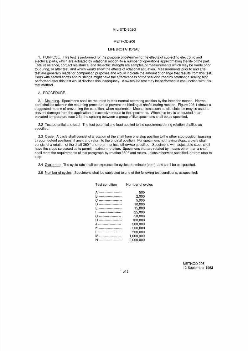
7/29/2019 TEST METHOD STANDARD ELECTRONIC AND ELECTRICAL COMPONENT PARTS
http://slidepdf.com/reader/full/test-method-standard-electronic-and-electrical-component-parts 85/191
MIL-STD-202G
METHOD 206
LIFE (ROTATIONAL)
1. PURPOSE. This test is performed for the purpose of determining the effects of subjecting electronic andelectrical parts, which are actuated by rotational motion, to a number of operations approximating the life of the part.Total resistance, contact resistance, and dielectric strength are samples of measurements which may be made priorto, during, or after test, and which would show the effects of rotational actuation. Measurements prior to and aftertest are generally made for comparison purposes and would indicate the amount of change that results from this test.Parts with sealed shafts and bushings might have the effectiveness of the seal disturbed by rotation; a sealing testperformed after this test would disclose this inadequacy. A switch-life test may be performed in conjunction with thistest method.
2. PROCEDURE.
2.1 Mounting. Specimens shall be mounted in their normal operating position by the intended means. Normalcare shall be taken in the mounting procedure to prevent the binding of shafts during rotation. Figure 206-1 shows asuggested means of preventing this condition, when applicable. Mechanisms such as slip clutches may be used toprevent damage from the application of excessive torque to the specimens. When this test is conducted at an
elevated temperature (see 2.6), the spacing between a group of like specimens shall be as specified.
2.2 Test potential and load. The test potential and load applied to the specimens during rotation shall be asspecified.
2.3 Cycle. A cycle shall consist of a rotation of the shaft from one stop position to the other stop position (passingthrough detent positions, if any), and return to the original position. For specimens not having stops, a cycle shall
consist of a rotation of the shaft 360° and return, unless otherwise specified. Specimens with adjustable stops shallhave the stops so placed as to permit maximum rotation. Specimens that are rotated by means other than a shaft
shall meet the requirements of this paragraph by rotation 360° and return, unless otherwise specified, or from stop tostop.
2.4 Cycle rate. The cycle rate shall be expressed in cycles per minute (cpm), and shall be as specified.
2.5 Number of cycles. Specimens shall be subjected to one of the following test conditions, as specified:
METHOD 20612 September 1963
1 of 2
Test condition Number of cycles
A -------------------- 500B -------------------- 2,000C -------------------- 5,000D -------------------- 10,000E -------------------- 15,000F -------------------- 25,000G ------------------- 50,000H -------------------- 100,000J -------------------- 200,000K -------------------- 300,000
L -------------------- 500,000M ------------------- 1,000,000N -------------------- 2,000,000

7/29/2019 TEST METHOD STANDARD ELECTRONIC AND ELECTRICAL COMPONENT PARTS
http://slidepdf.com/reader/full/test-method-standard-electronic-and-electrical-component-parts 86/191
MIL-STD-202G
NOTE: Metric equivalents are in parentheses.
FIGURE 206-1. Suggested mounting fixture for rotational-life test.
2.6 Temperature and atmospheric pressure. When specified, this test shall be performed at elevated or reducedtemperature and at other than room ambient atmospheric pressure.
3. MEASUREMENTS. Specified measurements or tests shall be made prior to, during, or after rotations, asspecified.
4. SUMMARY. The following details are to be specified in the individual specification:
a. Spacing of specimens for elevated-temperature testing, when applicable (see 2.1).
b. Test potential and load (see 2.2).
c. Cycle, if other than specified (see 2.3).
d. Cycle rate in cpm (see 2.4).
e. Test condition letter (see 2.5).
f. Temperature and atmospheric conditions, when applicable (see 2.6).
g. Measurements or tests prior to, during, or after rotations, as applicable (see 3).
METHOD 20612 September 1963
2

7/29/2019 TEST METHOD STANDARD ELECTRONIC AND ELECTRICAL COMPONENT PARTS
http://slidepdf.com/reader/full/test-method-standard-electronic-and-electrical-component-parts 87/191
MIL-STD-202G
METHOD 207B
HIGH-IMPACT SHOCK
1. PURPOSE. This test is performed for the purpose of determining the ability of various parts to withstand shockof the same severity as that produced by underwater explosions, collision impacts, near-miss gunfire, blasts causedby air explosions, and field conditions. Exact simulation of some of the severe shock motions experienced in the fieldis difficult to reproduce; however, parts that successfully complete the test of this method have been found to possessthe necessary ruggedness for this use. The test apparatus utilized in this method is the same as that designated asShock Testing Machine for Lightweight Equipment in MIL-S-901, Shock Tests, HI (High-Impact), ShipboardMachinery, Equipment and Systems, Requirements for. The purpose of this apparatus is to determine the ability ofequipment installed aboard naval ships to withstand shock and still continue to perform its operational function. Thistest method is limited to testing of parts weighing not more than 300 pounds.
2. PRECAUTIONS. The apparatus shall be examined periodically for damage. Any hardware that has becomedefective by being deformed or cracked shall be replaced. Particular attention shall be given to the anvil plate whichshall not be bowed more than 1 inch at the center. Proper safeguards shall be taken to protect personnel fromobjects that may become loosened and act as projectiles as a result of this test. A sound-warning arrangement shallbe made, for use in alerting personnel in the vicinity of the test of the impending drop of the hammer.
3. APPARATUS. The apparatus used in this test method shall be as shown on figure 207-1 and the associateddetail drawings. The parts shall be installed on a mounting fixture which is attached to the anvil plate of the shock-testing apparatus. A 400-pound hammer shall be dropped from a specified height (see 4.4) onto a shock pad locatedon the anvil plate. The shock motion is then transmitted by the anvil plate to the parts attached on the mountingfixture.
3.1 Anvil plate. The test apparatus of this method is so constructed that the anvil plate (see figure 207-3) can beinstalled, in sequence, in two positions. By utilizing these two installation positions and separately employing bothhammers of the apparatus shock is applied through the three principal mutually perpendicular axes of the part beingsubjected to test. One position is to locate the anvil in such a manner that it will receive blows through the back of theanvil plate by contact from the horizontal hammer, and blows on the top shock pad of the anvil plate by a drop of thevertical hammer as shown on figure 207-2. The other position is as shown on figure 207-1, whereby the end shockpad is contacted by the horizontal hammer.
3.2 Hammers. The test apparatus is equipped with two 400-pound hammers. One hammer renders a blow by avertical drop. The other hammer applies a force in a horizontal direction. In this manner, and by changing theorientation of the anvil plate, blows may be delivered to the anvil and the parts in three directions.
3.3 Mounting fixtures. Figure 207-4A, figure 207-4B, figure 207-5, and figure 207-6 show standard mountingfixtures that shall be used when testing parts with this test apparatus. These mounting fixtures simulate platform andpanel mountings. The applicable mounting fixture shall be as specified. When one of the standard mounting fixturesshown on figure 207-4A, figure 207-4B, figure 207-5, and figure 207-6 cannot be used, the individual specificationshall specify a mounting fixture or adapter which approximates the actual rigidity encountered in service.
METHOD 207B8 February 2002
1 of 16

7/29/2019 TEST METHOD STANDARD ELECTRONIC AND ELECTRICAL COMPONENT PARTS
http://slidepdf.com/reader/full/test-method-standard-electronic-and-electrical-component-parts 88/191
MIL-STD-202G
FIGURE 207-1. High-impact shock-testing apparatus.
METHOD 207B 8 February 2002
2

7/29/2019 TEST METHOD STANDARD ELECTRONIC AND ELECTRICAL COMPONENT PARTS
http://slidepdf.com/reader/full/test-method-standard-electronic-and-electrical-component-parts 89/191
MIL-STD-202G
FIGURE 207-2. High-impact shock-testing apparatus (backview) with anvil platelocated for back and top blows.
METHOD 207B8 February 2002
3
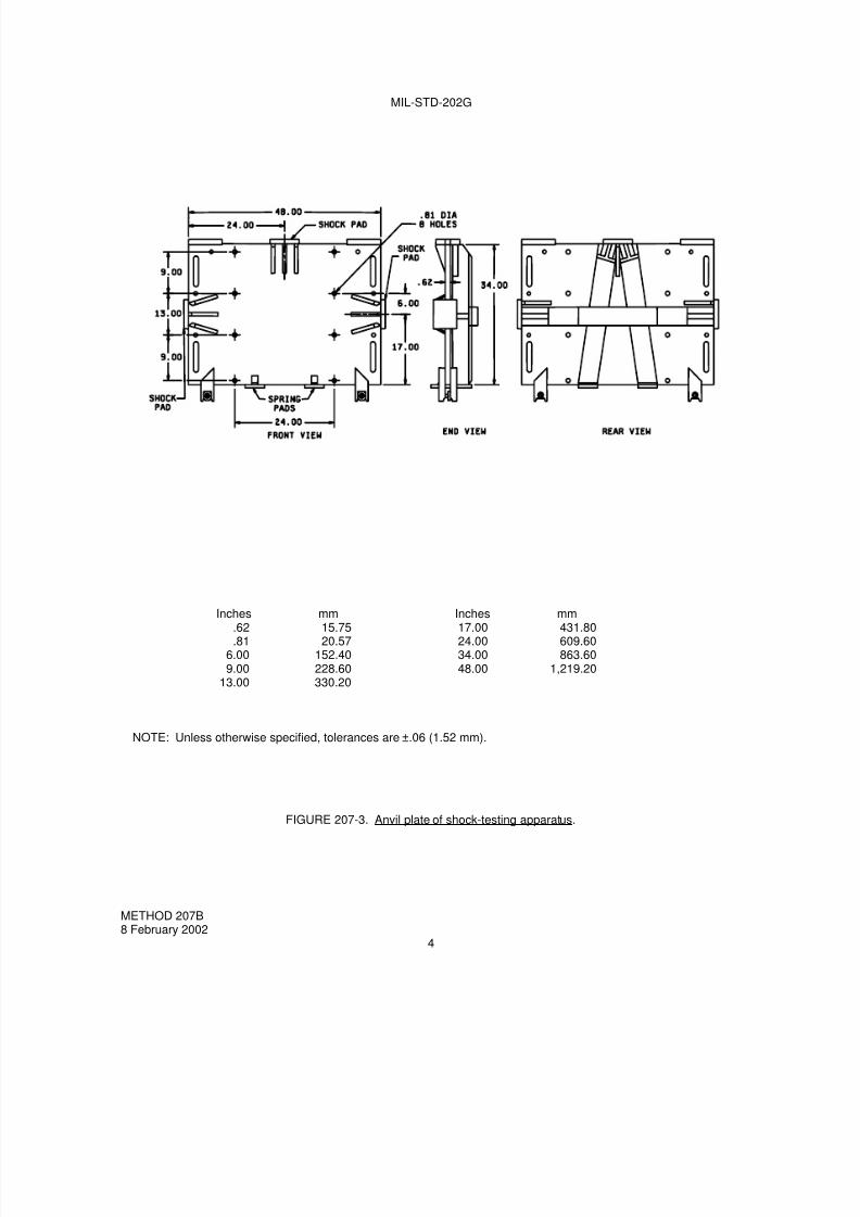
7/29/2019 TEST METHOD STANDARD ELECTRONIC AND ELECTRICAL COMPONENT PARTS
http://slidepdf.com/reader/full/test-method-standard-electronic-and-electrical-component-parts 90/191
MIL-STD-202G
Inches mm Inches mm.62 15.75 17.00 431.80.81 20.57 24.00 609.60
6.00 152.40 34.00 863.609.00 228.60 48.00 1,219.20
13.00 330.20
NOTE: Unless otherwise specified, tolerances are ±.06 (1.52 mm).
FIGURE 207-3. Anvil plate of shock-testing apparatus.
METHOD 207B 8 February 2002
4

7/29/2019 TEST METHOD STANDARD ELECTRONIC AND ELECTRICAL COMPONENT PARTS
http://slidepdf.com/reader/full/test-method-standard-electronic-and-electrical-component-parts 91/191
MIL-STD-202G
FIGURE 207-4A. Standard mounting fixtures for electrical-indicating switchboard metersand other panel-mounted parts.
METHOD 207B8 February 2002
5

7/29/2019 TEST METHOD STANDARD ELECTRONIC AND ELECTRICAL COMPONENT PARTS
http://slidepdf.com/reader/full/test-method-standard-electronic-and-electrical-component-parts 92/191
MIL-STD-202G
FIGURE 207-4A. Standard mounting fixtures for electrical-indicating switchboard metersand other panel-mounted parts - Continued.
METHOD 207B8 February 2002
6

7/29/2019 TEST METHOD STANDARD ELECTRONIC AND ELECTRICAL COMPONENT PARTS
http://slidepdf.com/reader/full/test-method-standard-electronic-and-electrical-component-parts 93/191

7/29/2019 TEST METHOD STANDARD ELECTRONIC AND ELECTRICAL COMPONENT PARTS
http://slidepdf.com/reader/full/test-method-standard-electronic-and-electrical-component-parts 94/191
MIL-STD-202G
FIGURE 207-4B. Standard mounting fixtures for electrical-indicating switchboardmeters and other panel-mounted parts.
METHOD 207B8 February 2002
8

7/29/2019 TEST METHOD STANDARD ELECTRONIC AND ELECTRICAL COMPONENT PARTS
http://slidepdf.com/reader/full/test-method-standard-electronic-and-electrical-component-parts 95/191
MIL-STD-202G
FIGURE 207-4B. Standard mounting fixtures for electrical-indicating switchboardmeters and other panel-mounted parts - Continued.
METHOD 207B8 February 2002
9
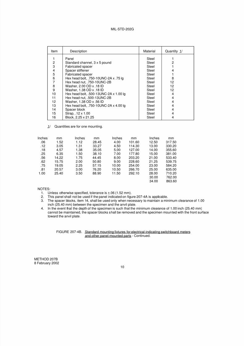
7/29/2019 TEST METHOD STANDARD ELECTRONIC AND ELECTRICAL COMPONENT PARTS
http://slidepdf.com/reader/full/test-method-standard-electronic-and-electrical-component-parts 96/191
MIL-STD-202G
Item Description Material Quantity 1/
1234567891011121314
1516
PanelStandard channel, 3 x 5 poundFabricated spacerSpacer stiffenerFabricated spacerHex head bolt, .750-10UNC-2A x .75 lgHex head nut, .750-10UNC-2BWasher, 2.00 OD x .18 IDWasher, 1.38 OD x .18 IDHex head bolt, .500-13UNC-2A x 1.00 lgHex head nut, .500-13UNC-2BWasher, 1.38 OD x .56 IDHex head bolt, .750-10UNC-2A x 4.00 lgSpacer block
Strap, .12 x 1.00Block, 2.25 x 21.25
SteelSteelSteelSteelSteelSteelSteelSteelSteelSteelSteelSteelSteelSteel
SteelSteel
121418
12121244444
44
1/ Quantities are for one mounting.
Inches mm Inches mm Inches mm Inches mm.06 1.52 1.12 28.45 4.00 101.60 12.50 317.50.12 3.05 1.31 33.27 4.50 114.30 13.00 330.20.18 4.57 1.38 35.05 5.00 127.00 14.00 355.60.25 6.35 1.50 38.10 7.00 177.80 15.00 381.00.56 14.22 1.75 44.45 8.00 203.20 21.00 533.40.62 15.75 2.00 50.80 9.00 228.60 21.25 539.75.75 19.05 2.25 57.15 10.00 254.00 23.00 584.20.81 20.57 3.00 76.20 10.50 266.70 25.00 635.00
1.00 25.40 3.50 88.90 11.50 292.10 28.00 710.2030.00 762.0034.00 863.60
NOTES:1. Unless otherwise specified, tolerance is ±.06 (1.52 mm).2. This panel shall not be used if the panel indicated on figure 207-4A is applicable.3. The spacer blocks, item 14, shall be used only when necessary to maintain a minimum clearance of 1.00
inch (25.40 mm) between the specimen and the anvil plate.4. In the event that the depth of the specimen is such that the minimum clearance of 1.00 inch (25.40 mm)
cannot be maintained, the spacer blocks shall be removed and the specimen mounted with the front surfacetoward the anvil plate.
FIGURE 207-4B. Standard mounting fixtures for electrical-indicating switchboard metersand other panel-mounted parts - Continued.
METHOD 207B8 February 2002
10

7/29/2019 TEST METHOD STANDARD ELECTRONIC AND ELECTRICAL COMPONENT PARTS
http://slidepdf.com/reader/full/test-method-standard-electronic-and-electrical-component-parts 97/191
MIL-STD-202G
1/ Quantities are for one mounting.2/ The size of the auxiliary mounting plate shall be increased to .50 x 36.00 x 34.00 for panels No. 5 and No. 6
listed in table II.
FIGURE 207-5. Standard mounting fixtures for electrical controller parts (contractors, relays, resistors, etc.).
METHOD 207B8 February 2002
11
Inches mm
.18 4.57
.50 12.70
.53 13.46
.62 15.75
.66 16.761.00 25.401.50 38.101.94 49.282.00 50.802.50 63.507.00 177.80
27.00 685.8034.00 863.6036.00 914.40
Item Description Material Quantity 1/
12
2/ 345
6789
Car building channel, 4 x 13.8 poundsCar building channel, 4 x 13.8 poundsAuxiliary mounting plate, .50 x 27.00 x 34.00Spacer (see table 1)Plastic mounting panel (see table 2)
Hex head bolt; .750-10UNC-2A x 7.00 lgHex head nut, .750-10UNC-2BWasher, 2.00 OD x .18 IDPipe spacer, 1.00 standard, 1.94 lg
SteelSteelSteelSteelPlastic, laminated, type FBG, inaccordance with MIL-I-24768/14Steel (heat-treated)SteelSteelSteel
111
88
168
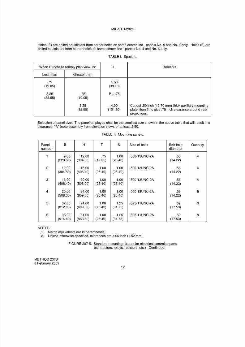
7/29/2019 TEST METHOD STANDARD ELECTRONIC AND ELECTRICAL COMPONENT PARTS
http://slidepdf.com/reader/full/test-method-standard-electronic-and-electrical-component-parts 98/191
MIL-STD-202G
Holes (E) are drilled equidistant from corner holes on same center line - panels No. 5 and No. 6 only. Holes (F) aredrilled equidistant from corner holes on same center line - panels No. 4 and No. 6 only.
TABLE I. Spacers.
When P (note assembly plan view) is: L Remarks
Less than Greater than
.75(19.05)
3.25(82.55)
.75(19.05)
3.25(82.55)
1.50(38.10)
P + .75
4.00(101.60)
Cut out .50 inch (12.70 mm) thick auxiliary mountingplate, item 3, to give .75 inch clearance around rearprojections.
Selection of panel size: The panel employed shall be the smallest size shown in the above table that will result in aclearance, "A" (note assembly front elevation view), of at least 2.50.
TABLE II. Mounting panels.
Panelnumber
B H T S Size of bolts Bolt-holediameter
Quantity
1
2
3
4
5
6
9.00(228.60)
12.00
(304.80)
16.00(406.40)
20.00(508.00)
32.00(812.80)
36.00(914.40)
12.00(304.80)
16.00
(406.40)
20.00(508.00)
24.00(609.60)
24.00(609.60)
34.00(863.60)
.75(19.05)
1.00
(25.40)
1.00(25.40)
1.00(25.40)
1.00(25.40)
1.00(25.40)
1.00(25.40)
1.00
(25.40)
1.00(25.40)
1.00(25.40)
1.25(31.75)
1.25(31.75)
.500-13UNC-2A
.500-13UNC-2A
.500-13UNC-2A
.500-13UNC-2A
.625-11UNC-2A
.625-11UNC-2A
.56(14.22)
.56
(14.22)
.56(14.22)
.56(14.22)
.69(17.53)
.69(17.53)
4
4
4
6
6
8
NOTES:
1. Metric equivalents are in parentheses.2. Unless otherwise specified, tolerances are ±.06 inch (1.52 mm).
FIGURE 207-5. Standard mounting fixtures for electrical controller parts(contractors, relays, resistors, etc.) - Continued.
METHOD 207B8 February 2002
12

7/29/2019 TEST METHOD STANDARD ELECTRONIC AND ELECTRICAL COMPONENT PARTS
http://slidepdf.com/reader/full/test-method-standard-electronic-and-electrical-component-parts 99/191
MIL-STD-202G
FIGURE 207-6. Standard mounting fixtures for deck, or platform, mounted parts.
METHOD 207B8 February 2002
13

7/29/2019 TEST METHOD STANDARD ELECTRONIC AND ELECTRICAL COMPONENT PARTS
http://slidepdf.com/reader/full/test-method-standard-electronic-and-electrical-component-parts 100/191

7/29/2019 TEST METHOD STANDARD ELECTRONIC AND ELECTRICAL COMPONENT PARTS
http://slidepdf.com/reader/full/test-method-standard-electronic-and-electrical-component-parts 101/191
MIL-STD-202G
Item Description Material Quantity 1/
123456789
1011121314
1516
Car building channel, 4 x 13.8 lbCar building channel, 4 x 13.8 lbAuxiliary mounting plate, .38Horizontal mounting plate, .50Hex head bolt, .750-10UNC-2A x 7.00 lgHex head nut, .750-10UNC-2BWasher, 2.00 OD x .18 IDPipe spacer, 1.00 standard, 2.81 lgGusset plate, .38Gusset plate, .38Gusset plate, .38Horizontal mounting plate, .50Horizontal mounting plate, .50Stiffener, .38
Auxiliary mounting plate, .38Auxiliary mounting plate, .38
SteelSteelSteelSteelSteel (heat-treated)Steel (heat treated)SteelSteelSteelSteelSteelSteelSteelSteel
SteelSteel
111166
126222114
11
1/ Quantities are for three mountings.
Inches mm Inches mm Inches mm Inches mm.18 4.57 1.25 31.75 9.00 228.60 20.00 508.00.25 6.35 1.50 38.10 11.00 279.60 24.00 609.60.38 9.65 2.00 50.80 12.00 304.80 26.50 647.70.50 12.70 2.50 63.50 12.38 314.45 27.00 685.80.62 15.75 2.81 71.73 13.00 330.20 27.75 704.85.81 20.57 3.00 76.20 15.00 381.00
1.00 25.40 7.00 177.80 16.00 406.40
NOTES:1. Unless otherwise specified, tolerance is ±.06 (1.52 mm).2. Mounting platform number 3 shall be similar to mounting platform number 2 with the exception of the
horizontal mounting plate and the side gusset plates shall be increased to 22.00 inches (558.80 mm).3. The smallest mounting platform which will satisfactorily accommodate the specimen shall be selected.4. If the deep gussets interfere with the mounted specimen, the extra bolt holes shall be used in bolting of
mounting platform number 1 in the inverted position to the four lower bolt holes of the anvil plate.
FIGURE 207-6. Standard mounting-fixtures for deck or platform mounted parts - Continued.
METHOD 207B8 February 2002
15

7/29/2019 TEST METHOD STANDARD ELECTRONIC AND ELECTRICAL COMPONENT PARTS
http://slidepdf.com/reader/full/test-method-standard-electronic-and-electrical-component-parts 102/191
MIL-STD-202G
4. PROCEDURE.
4.1 Mounting method. The specimens shall be installed by their normal mounting means on the mounting fixture
in their normal operating position. Bolts for mounting the parts shall conform to type I, type II, or type III, grade 2, ofMIL-DTL-1222, Studs, Bolts, Hex Cap Screws, Socket Head Cap Screws and Nuts. Mounting bolts shall be checkedfor tightness before each blow. Care shall be taken in the mounting procedure to prevent initial stresses beingapplied to the specimens prior to shock.
4.2 Anvil-plate bolts and positioning springs. Due to the severity of the shock applied to the anvil plate by a seriesof three blows, the anvil-plate bolts shall be checked for tightness before each series of blows. The spacing betweenstops of the positioning springs (1.5 inches) shall also be corrected before each succession of blows.
4.3 Direction of shock. A total of nine blows, three through each of the three principal mutually perpendicular axesfor the heights indicated in 4.4, shall be delivered to the anvil plate supporting the specimens under test. Direction ofthe shock shall be, in order, to the back, top, and side. Back and top blows shall be applied with the anvil platelocated to receive blows from the horizontal and vertical hammers. Side blows are delivered by the horizontalhammer contacting the end shock pad of the anvil plate (see 3.1).
4.4 Height of hammer drops. The hammer shall strike the shock pad on the anvil plate, in sequence, from heightsof 1 foot, 3 feet, and 5 feet.
4.5 Hammer supports. During the test, the hammer not in use shall be disengaged from the lifting cable andsupported so that the hammer and its support are not in contact with the anvil plate.
4.6 Electrical load and operating conditions. The electrical load and operating conditions applied to the specimensshall be as specified.
4.7 External resilient mountings. Unless otherwise specified, no external resilient mountings associated with thespecimen being tested shall be used. Integral mounting devices and external resilient mountings (if specified)associated with the specimen shall remain unblocked during tests.
5. MEASUREMENTS. Monitoring of the specimens during test (e.g., delayed contact opening of relays,momentary stopping of dynamotors, calibration errors in meters) shall be as specified. Upon completion of the
required number of blows, electrical and physical measurements shall be made as specified. Allowable tolerancesshall be as specified.
6. SUMMARY. The following details are to be specified in the individual specification:
a. Mounting fixtures (see 3.3).
b. Electrical load on operating conditions, if applicable (see 4.6).
c. External resilient mountings, if required (see 4.7).
d. Monitoring during test, measurements after test, and allowable tolerances, as applicable (see 5).
METHOD 207B8 February 2002
16

7/29/2019 TEST METHOD STANDARD ELECTRONIC AND ELECTRICAL COMPONENT PARTS
http://slidepdf.com/reader/full/test-method-standard-electronic-and-electrical-component-parts 103/191
MIL-STD-202G
METHOD 208H
SOLDERABILITY
1. PURPOSE. The purpose of this test method is to determine the solderability of all terminations which arenormally joined by a soldering operation. This determination is made on the basis of the ability of these terminationsto be wetted by solder and the predictability of a suitable fillet resulting from solder application. These procedures willverify that the pre-assembly lead finish provides a solderable surface of sufficient quality to enable satisfactorysoldering.
2. PROCEDURE. The solderability test shall be performed in accordance with ANSI/J-STD-002 “SolderabiiltyTests for Component Leads, Terminations, Lugs, Terminals and Wires” and herein. The following details andexceptions shall apply:
2.1 Contractual agreements. The contractual agreements statement in ANSI/J-STD-002 shall not apply. Anyexceptions to the requirements specified in ANSI/J-STD-002 and this test method shall be documented in theindividual military procurement document or approved by the procuring military activity.
2.2 Coating durability. The coating durability category (from ANSI/J-STD-002) shall be as follows:
a. Category 2 - for stranded wire (1 hour ±5 minutes steam aging with insulation removed).
b. Category 3 - for all other components (8 hours ±15 minutes steam aging).
2.3 Test method. The test method used (from ANSI/J-STD-002) shall be as follows:
a. Test A - for through-hole mount and surface mount leaded components, solid wire less than .045 inchdiameter and stranded wire 18 AWG or smaller. If not otherwise specified in the procurement document,
angle of immersion for surface mount leaded components shall be 90°.
b. Test B - for surface mount leadless components.
c. Test C - for lugs, tabs, terminals, solid wire greater than .045 inch diameter and stranded wire larger than 18AWG.
3. SOLDERING IRON TEST METHOD. When specified in the individual specification, the soldering iron testmethod shall be performed as specified herein.
3.1 Apparatus. The soldering iron used shall be temperature controlled and shall be capable of maintaining themeasured idling tip temperature within ±5.5°C. Three-wire cords and tip grounding shall be used. The solder ironshall be of such design as to provide zero voltage switching. Solder guns of the transformer type shall not be used.
3.2 Materials. The solder shall be composition Sn60Pb40A or Sn63Pb37A of ANSI/J-006 “Requirements forElectronic Grade Solder Alloys and Fluxed and Non-Fluxed Solid Solders for Electronic Soldering Applications”. Thesolder shall be of form W, flux symbol A, flux percentage symbol 6 or 7 (see ANSI/J-STD-006).
3.3 Procedure. Preparation of terminations and aging shall be as specified in ANSI/J-STD-002 and 2.2 above.Flux shall be applied by a suitable method (e.g., brush) and allowed to drain for 5 to 20 seconds. Solder inaccordance with 3.2 shall be applied to the terminal along with the clean solder coated tip of an iron (unless otherwisespecified in the individual specification, iron temperature shall be 350°C) to a point ¼ inch from the nearest insulatingmaterial or ½ the exposed length of the terminal, whichever is closer. The termination shall be positioned so that theiron can be applied to the test surface in a horizontal position as in figure 208-1. Unless otherwise specified in theindividual specification, the iron shall be applied for a period of 5 ±0.5 seconds and shall remain stationary during thisperiod. Only enough solder shall be applied to flow a single thin layer of new solder.
METHOD 208H31 January 1996
1 of 2

7/29/2019 TEST METHOD STANDARD ELECTRONIC AND ELECTRICAL COMPONENT PARTS
http://slidepdf.com/reader/full/test-method-standard-electronic-and-electrical-component-parts 104/191
MIL-STD-202G
Should mechanical support for the termination be required while performing this test, such support shall be ofthermally insulating material. For solder cups, the cup shall be filled with solder in accordance with 3.2, and theexcess solder wicked out with a compatible fluxed solder wick. Prior to examination, flux residue shall be removed
from the terminations by cleaning in a suitable solvent. Terminations shall be examined as specified inANSI/J-STD-002.
4. SUMMARY. The following details shall be specified in the applicable procurement document.
a. Depth of immersion if other than specified.
b. Angle of immersion for surface mount leaded components, if other than 90°.
c. Measurements after test, when applicable.
d. Whether soldering iron method is to be used.
1. Soldering iron temperature if other than 350°C.
2. Duration of application of soldering iron if other than 5 ±0.5 seconds.
FIGURE 208-1. Soldering iron position and process diagram.
METHOD 208H31 January 1996
2

7/29/2019 TEST METHOD STANDARD ELECTRONIC AND ELECTRICAL COMPONENT PARTS
http://slidepdf.com/reader/full/test-method-standard-electronic-and-electrical-component-parts 105/191
MIL-STD-202G
METHOD 209
RADIOGRAPHIC INSPECTION
1. PURPOSE. Radiographic inspection is generally a nondestructive (see 1.1) method for detecting internalphysical defects in small component parts which are not otherwise visible. Radiographic techniques are intended toreveal such flaws as improper positioning of elements, voids in encapsulating or potting compounds, inhomogeneitiesin materials, presence of foreign materials, broken elements, etc.
1.1 Precautions. Radiographic inspection may be performed on most parts; however, radiation may causechanges in electrical behavior of some materials.
2. APPARATUS AND MATERIALS.
2.1 Radiographic equipment. The radiographic equipment used shall be capable of producing the requiredradiographic quality as specified in the individual specification. When using X-ray equipment, X-ray tubes with smalleffective focal-spot sizes and low inherent filtration are recommended.
2.2 Film holder. A lightproof film holder of low inherent filtration to radiation is recommended when using voltages
of 50 kilovolts. A lead backing plate should be used behind the film holder to minimize fogging due to secondaryback-scatter.
2.3 Image-quality indicator. The image-quality indicators used to indicate radiographic sensitivity shall be asspecified in the individual specification. The sensitivity is the combined measure of the definition and contrast of theradiograph and should be such that the maximum allowable defect shall be shown. The image-quality indicator maybe made from a sample part of the same type as the part being radiographed and should contain either an actual orsimulated defect which is at least 10 percent smaller than the smallest defect to be detected.
2.4 Film. The film shall be compatible with the sensitivity required in 2.1. In general, finer detail is achieved by theuse of finer grain films with lower exposure indexes. If extreme magnification techniques are required, the use ofsingle emulsion films is recommended.
2.5 Nonfilm techniques. Nonfilm techniques may be used if required sensitivity levels, and records (whenspecified) can be obtained (see 2.1).
2.6 Personnel safety precautions. The safety precautions described in National Bureau of Standards (NBS)Handbook 76 - X-Ray Protection; NBS Handbook 73 - Protection Against Radiations From Sealed Gamma Sources;Atomic Energy Commission Book Title 10, Part 20 - Standard for Protection Against Radiation, Part 30 - Licensing ofBy-product Material, Part 31 - Radiation Safety Requirements for Radiographic Operations, shall be complied withwhen applicable.
3. PROCEDURE.
3.1 Positioning of specimen. The leaded film holder is backed up by the lead plate (see 2.2), and the specimen tobe radiographed shall be placed in the position or positions specified in the individual specification.
METHOD 20918 May 1962
1 of 3

7/29/2019 TEST METHOD STANDARD ELECTRONIC AND ELECTRICAL COMPONENT PARTS
http://slidepdf.com/reader/full/test-method-standard-electronic-and-electrical-component-parts 106/191
MIL-STD-202G
3.2 Exposure parameters. The following exposure parameters may be varied to obtain the radiographic qualityspecified in 2.1:
a. Source - film distance.
b. Kilovoltage or type of isotope.
c. Milliamperage or source strength of isotope.
d. Exposure time.
e. Film speed.
f. Intensifying screen.
The detail sensitivity is affected by the following:
a. Focal spot size.
b. Film grain size.
c. Nature of the specimen.
d. Placement of the specimen.
The above factors should be taken into consideration when determining the exposure parameters.
3.3 Intensifying screens. In general, metallic intensifying screens should be used at X-ray tube voltages above 125kilovolts to minimize fogging and for intensifying effects.
3.4 identification of radiographs. Suitable means shall be employed to identify individual specimens on theradiographic record.
3.5 Marking of radiographed specimens. If required, suitable marking shall be specified in the individualspecification indicating that specimens have been inspected radiographically.
4. EVALUATIONS. The final image shall be examined with suitable viewing equipment, which may includemagnification, to determine such defects as improper positioning of elements, voids in encapsulating or pottingcompounds; inhomogeneities in materials; presence of foreign materials; broken elements; and other defects asspecified in the individual specification.
METHOD 20918 May 1962
2
7/29/2019 TEST METHOD STANDARD ELECTRONIC AND ELECTRICAL COMPONENT PARTS
http://slidepdf.com/reader/full/test-method-standard-electronic-and-electrical-component-parts 107/191

7/29/2019 TEST METHOD STANDARD ELECTRONIC AND ELECTRICAL COMPONENT PARTS
http://slidepdf.com/reader/full/test-method-standard-electronic-and-electrical-component-parts 108/191

7/29/2019 TEST METHOD STANDARD ELECTRONIC AND ELECTRICAL COMPONENT PARTS
http://slidepdf.com/reader/full/test-method-standard-electronic-and-electrical-component-parts 109/191
MIL-STD-202G
METHOD 210F
RESISTANCE TO SOLDERING HEAT
1. PURPOSE. This test is performed to determine whether wire and other component parts can withstand theeffects of the heat to which they will be subjected during the soldering process (solder iron, solder dip, solder wave,or solder reflow). The heat can be either conducted heat through the termination into the component part, or radiantheat from the solder bath when in close proximity to the body of the component part, or both. The solder dip methodis used as a reasonably close simulation of the conditions encountered in wave soldering, in regard to radiated andconducted heat. This test also is intended to evaluate the impact of reflow techniques to which components may beexposed. The heat of soldering can cause solder reflow which may affect the electrical characteristics of thecomponent part and may cause mechanical damage to the materials making up the part, such as loosening ofterminations or windings, softening of insulation, opening of solder seals, and weakening of mechanical joints.
2. APPARATUS.
2.1 Solder pot. A static solder pot, of sufficient size to accommodate the mounting board (see 2.4) and to Immersethe terminations to the depth specified for the solder dip (without touching the bottom of the pot), shall be used. Thisapparatus shall be capable of maintaining the solder at the temperature specified. The solder bath temperature shall
be measured in the center of the pot at a depth of at least .500 inch (12.7 mm), but no deeper than 1 inch (25.4 mm)below the surface of the solder.
2.2 Heat sinks or shielding. The use of heat sinks or shielding is prohibited except when it is a part of thecomponent. When applicable, heat sinks or shielding shall be specified in the individual specification, including all ofthe details, such as materials, dimensions, method of attachment, and location of the necessary protection.
2.3 Fixtures. Fixtures, when required, shall be made of a non-solderable material designed so that they will makeminimum contact (i.e., minimum heat sink) with the component. Further, they shall not place undue stress on thecomponent when fixtured.
2.4 Mounting board. A mounting board, in accordance with NEMA grade FR-4 of IPC-4101, 9 square inches(i.e., 3 x 3, 1 x 9, etc.), minimum area, .062 inch ±.0075 inch (1.57 mm ±.191 mm) thick, shall be used, unlessotherwise specified. Component lead holes shall be drilled such that the diametrical clearance between the hole andcomponent terminals shall not exceed .015 inch (0.38 mm). Metal eyelets or feed-throughs shall not be used.
Surface mount boards, when specified in the individual specification, shall have pads of sufficient size and number toaccommodate the component being tested.
2.5 Solder iron. A solder iron, capable of maintaining a temperature of 350°C ±10°C, shall be used.
2.6 Reflow chambers. The reflow chambers or equivalent (Vapor Phase Reflow (VPR) chamber, Infrared Reflow(IRR) oven, air circulating oven, etc.) shall be of sufficient size to accommodate the mounting board and componentsto be tested. The chamber shall be capable of generating the specified heating rate, temperatures, andenvironments.
2.7 Temperature measurement. Low mass thermocouples that do not affect the heating rate of the sample shallbe used. A temperature recording device is recommended. The equipment shall be capable of maintaining anaccuracy of ±1°C at the temperature range of interest.
3. MATERIALS.
3.1 Solder. The solder or solder paste shall be tin-lead alloy with a nominal tin content of 50 percent to 70 percentin accordance with ANSI/J-STD-006, “Requirements for Electronic Grade Solder Alloys and Fluxed and Non-FluxedSolid Solders for Electronic Soldering Applications” or ANSI/J-STD-005, “Requirements for Soldering Pastes”. Whenspecified in the individual specification, other solders can be used provided they are molten at the specifiedtemperature.
METHOD 210F8 February 2002
1 of 7

7/29/2019 TEST METHOD STANDARD ELECTRONIC AND ELECTRICAL COMPONENT PARTS
http://slidepdf.com/reader/full/test-method-standard-electronic-and-electrical-component-parts 110/191
MIL-STD-202G
3.2 Flux. When flux is used, it shall conform to type A of ANSI/J-STD-004, “Requirements for Soldering Fluxes”, oras specified in the individual specification.
3.3 VPR fluid. A perfluorocarbon fluid that has a boiling point of 215°C shall be used.
4. PROCEDURE.
4.1 Special preparation of specimens. Any special preparation of specimens prior to testing shall be as specifiedin the individual specification. This could include specific instructions such as bending or any other relocation ofterminations, cleaning, application of flux, pretinning, or attachment of heat sinks or protective shielding (see 2.2),prior to the solder immersion.
4.2 Preparation of solder bath. The molten solder shall be agitated to assure that the temperature is uniform. Thesurface of the solder shall be kept clean and bright.
4.3 Application of flux. When flux is used, the terminations to be tested shall be immersed in the flux (see 3.2),which is at room ambient temperature, to the depth specified for the solder dip. The duration of the immersion shallbe from 5 seconds to 10 seconds.
4.4 Test conditions. Unless otherwise specified in the individual specification, the test shall be performed on allsolder terminations attached to the component part. There are six types of soldering techniques covered by thesetest conditions. The test conditions are outlined below and in table I.
Test condition A: Solder iron - Hand soldering of solder cups, through hole components, tab and postterminations, solder eyelet terminations.
Test condition B: Solder dip - Simulates hot solder dipping (tinning) of leaded components.
Test condition C: Wave solder - Simulates wave solder of topside board mount product.
Test condition D: Wave solder - Simulates wave solder of bottomside board mount product.
Test condition H: VPR - VPR environment without preheat.
Test conditions I, J, K: Infrared/Convection reflow - Simulates IRR, natural convection, and forced airconvection reflow environments.
4.4.1 Test condition A: Solder iron.
a. When testing a solder cup, tab and post termination, or solder eyelet termination, the applicable wire size,properly prepared for the solder termination, shall be attached in the appropriate manner.
When testing a board mount component, the component shall be placed on a mounting board (see 2.4).
b. When specified, the components shall be fluxed (see 4.3).
c. Unless otherwise specified, a solder iron in accordance with 2.5 shall be used.
d. The solder iron shall be heated to 350°C ±10°C and applied to the termination for a duration of 4 seconds to5 seconds as specified in table I. The solder and iron shall be applied to the area of the assembly closest tothe component body that the product is likely to experience. For surface mount components, the iron shallbe placed on the pad only.
METHOD 210F8 February 2002
2
7/29/2019 TEST METHOD STANDARD ELECTRONIC AND ELECTRICAL COMPONENT PARTS
http://slidepdf.com/reader/full/test-method-standard-electronic-and-electrical-component-parts 111/191
MIL-STD-202G
e. Remove the iron and allow the component to cool and stabilize at room ambient conditions. If flux wasused, the component shall be cleaned using an appropriate cleaning solution.
f. The component shall be visually examined under 10X magnification.
4.4.2 Test condition B: Solder dip.
a. Place the component in an appropriate fixture (see 2.3).
b. When specified, the leads shall be fluxed (see 4.3).
c. The specific combination of temperature, immersion and emersion rate, immersion duration, and number ofheats shall be as specified in table I. Unless otherwise specified, terminations shall be immersed to within.050 inch (1.27 mm) of the component body. Terminations shall be immersed simultaneously, if thegeometry of the component permits.
d. After the solder dip, the component shall be allowed to cool and stabilize at room ambient conditions. If fluxwas used, the component shall be cleaned using an appropriate cleaning solution.
e. The component shall be visually examined under 10X magnification.
4.4.3 Test condition C: Wave solder - topside board mount component.
a. The component under test shall be mounted on a mounting board (see 2.4).
Wire leads: Wire leads shall be brought through the board holes and bent at least 30 degrees from a lineperpendicular to the board. Leads shall extend from .050 inch to .100 inch (1.27 mm to 2.54 mm) from the
bottom of the board. Axial leads shall be bent at a 90° angle at a point between .06 inch and .08 inch (1.5mm and 2.1 mm) from the body, eyelet fillet or weld unless otherwise specified (see figure 210-1).
Pin leads: Where the component is designed with rigid pin leads, the full length of the termination shall beretained. Pin leads shall not be cut or bent (see figure 210-1).
b. When specified, the leads shall be fluxed (see 4.3).
c. The specific combination of temperature, duration, and number of heats shall be as specified in table I.
d. The components, mounted on the board, shall be immersed in the solder pot so that the bottom of the boardfloats on the molten solder.
e. After the float, the components shall be allowed to cool and stabilize at room ambient conditions. If flux wasused, the components shall be cleaned using an appropriate cleaning solution.
f. The components shall be visually examined under 10X magnification.
4.4.4 Test condition D: Wave solder - bottomside board mount product.
a. Place the component in an appropriate fixture (see 2.3).
b. When specified, the terminations shall be fluxed (see 4.3).
c. The specific combination of temperature, preheat conditions, immersion and emersion rates, immersionduration, and number of heats shall be as specified in table I.
METHOD 210F 8 February 2002
3

7/29/2019 TEST METHOD STANDARD ELECTRONIC AND ELECTRICAL COMPONENT PARTS
http://slidepdf.com/reader/full/test-method-standard-electronic-and-electrical-component-parts 112/191
MIL-STD-202G
d. The component shall be preheated and fully immersed in the solder bath in accordance with 4.4.4c.
e. After the immersion, the component shall be allowed to cool and stabilize at room ambient conditions. If flux
was used, the component shall be cleaned using an appropriate cleaning solution.
f. The component shall be visually examined under 10X magnification.
4.4.5 Test condition H: Vapor phase reflow soldering.
a. Components shall be mounted on a mounting board (see 2.4). Through-hole mounted components shallhave their terminals inserted into the termination holes. Surface mount components shall be placed on topof the board.
b. A test chamber (see 2.6) shall be used which is large enough to suspend the mounting board withouttouching the sides or the solution. The VPR fluid shall be placed in the test chamber and shall be heateduntil it is boiling. The solution shall be allowed to boil for 5 minutes prior to suspending the mounting board.
c. The specific combination of temperature, duration of exposure, and number of heats shall be as specified in
table I.
d. After chamber equalization, the mounting board shall be suspended into the vapor in a horizontal plane.The mounting board shall not touch the solution.
e. After the heat, the components shall be allowed to cool and stabilize at room ambient conditions. If a solderpaste was used, the component shall be cleaned using an appropriate solution.
f. The components shall be visually examined under 10X magnification.
4.4.6 Test conditions I, J, K: Infared/convection reflow soldering.
a. Components shall be mounted on a mounting board (see 2.4). Through-hole mounted components shallhave their terminals inserted into the termination holes. Surface mount components shall be placed on topof the board.
b. A test chamber as specified in 2.6 shall be used.
c. A low mass thermocouple shall be attached tightly to the component at an appropriate position away fromthe edges.
d. The specific combination of temperature, preheat, duration, and number of heats shall be as specified bytest condition I, J, or K in table I and the individual procurement document.
e. The board shall be placed into the test chamber and the temperature of the component ramped at a rate of1°C/s to 4°C/s as measured by the thermocouple. The assembly shall be above 183°C for 90 seconds to120 seconds and held at the final temperature and time designated by the test condition. The assemblyshall then be allowed to cool to room ambient temperature. This constitutes one heat cycle. The assemblyshall be exposed to three heat cycles.
f. The components shall be visually examined under 10X magnification.
METHOD 210F8 February 2002
4
7/29/2019 TEST METHOD STANDARD ELECTRONIC AND ELECTRICAL COMPONENT PARTS
http://slidepdf.com/reader/full/test-method-standard-electronic-and-electrical-component-parts 113/191
MIL-STD-202G
5. EXAMINATIONS AND MEASUREMENTS. Examinations and measurements to be made before and after thetest, as applicable, shall be as specified in the individual specification. After the procedure, the specimens shall beallowed to cool and stabilize at room ambient conditions, for the time specified in the individual specification.
5.1 Internal examination. When specified, internal examination of the part shall be made after the test to check forsolder reflow or heat damage.
6. SUMMARY. The following details are to be specified in the individual specification:
a. The use of heat sinks or shielding is prohibited except when they are part of the component (see 2.2).
b. Mounting board, if different from that specified (see 2.4).
c. Solder, if different from that specified (see 3.1).
d. Flux, if applicable and if different from that specified (see 3.2, 4.1, and 4.3).
e. Solder terminations that are not to be tested, if applicable (see 4.4).
f. Special preparation of specimens if applicable (see 4.1).
g. Depth of immersion in the molten solder, if different from that specified (see 4.4.2).
h. Test condition letter (see 4.4).
i. Cooling time prior to final examinations and measurements (see 4.4 and 5).
j. Examinations and measurements before and after test, as applicable (see 5).
k. Method of internal inspection, if required (see 5.1).
METHOD 210F 8 February 2002
5
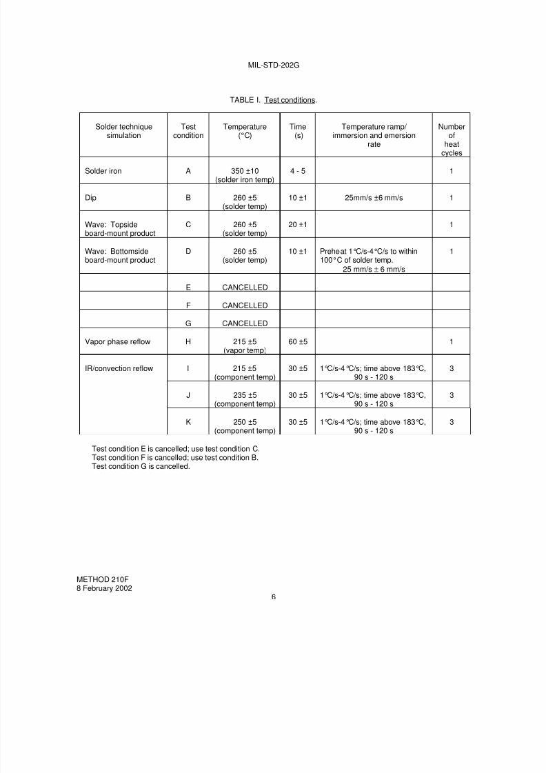
7/29/2019 TEST METHOD STANDARD ELECTRONIC AND ELECTRICAL COMPONENT PARTS
http://slidepdf.com/reader/full/test-method-standard-electronic-and-electrical-component-parts 114/191
MIL-STD-202G
TABLE I. Test conditions.
Solder techniquesimulation
Testcondition
Temperature(°C)
Time(s)
Temperature ramp/ immersion and emersion
rate
Numberof
heatcycles
Solder iron A 350 ±10(solder iron temp)
4 - 5 1
Dip B 260 ±5(solder temp)
10 ±1 25mm/s ±6 mm/s 1
Wave: Topsideboard-mount product
C 260 ±5(solder temp)
20 ±1 1
Wave: Bottomside
board-mount product
D 260 ±5
(solder temp)
10 ±1 Preheat 1°C/s-4°C/s to within
100°C of solder temp.25 mm/s ± 6 mm/s
1
E CANCELLED
F CANCELLED
G CANCELLED
Vapor phase reflow H 215 ±5(vapor temp)
60 ±5 1
IR/convection reflow I 215 ±5(component temp)
30 ±5 1°C/s-4°C/s; time above 183°C,90 s - 120 s
3
J 235 ±5(component temp)
30 ±5 1°C/s-4°C/s; time above 183°C,90 s - 120 s
3
K 250 ±5(component temp)
30 ±5 1°C/s-4°C/s; time above 183°C,90 s - 120 s
3
Test condition E is cancelled; use test condition C.Test condition F is cancelled; use test condition B.Test condition G is cancelled.
METHOD 210F8 February 2002
6
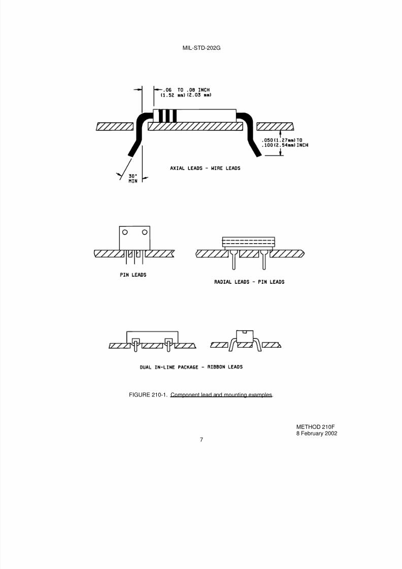
7/29/2019 TEST METHOD STANDARD ELECTRONIC AND ELECTRICAL COMPONENT PARTS
http://slidepdf.com/reader/full/test-method-standard-electronic-and-electrical-component-parts 115/191
MIL-STD-202G
FIGURE 210-1. Component lead and mounting examples.
METHOD 210F8 February 2002
7

7/29/2019 TEST METHOD STANDARD ELECTRONIC AND ELECTRICAL COMPONENT PARTS
http://slidepdf.com/reader/full/test-method-standard-electronic-and-electrical-component-parts 116/191

7/29/2019 TEST METHOD STANDARD ELECTRONIC AND ELECTRICAL COMPONENT PARTS
http://slidepdf.com/reader/full/test-method-standard-electronic-and-electrical-component-parts 117/191
M IL-STD-202G
METHOD 211A
TERMINAL STRENGTH
1. PURPOSE. This test is performed to determine whether the design of the terminals and their method ofattachment can withstand one or more of the applicable mechanical stresses to which they will be subjected duringinstallation or disassembly in equipment. These stresses must be withstood by the component part withoutsustaining damage which would affect either the utility of the terminals or the operation of the component part itself.Evidence of damage caused by this test may not become evident until subsequent environmental tests areperformed, such as seal, moisture resistance, or life. Procedures are established in this method for testing wire-leadterminals, flexible-flat-strip or tab-lead terminals, and rigid-type terminals which are threaded or have otherarrangements for attaching conductors. The forces applied consist of direct axial, radial or tension pulls, twist,bending torsion, and the torque exerted by the application of nuts or screws on threaded terminals. These appliedstresses will disclose poor workmanship, faulty designs, and inadequate methods of attaching terminals to the bodyof the part. Other evidence of damage may be disclosed by mechanical distortion of the part, breaking of seals,cracking of materials surrounding the terminals, or changes in electrical characteristics, such as shorted orinterrupted circuits and changes in resistance values.
2. TEST CONDITIONS.
2.1 Selection. In this method there are five test conditions, A, B, C, D, and E. The selection of test conditions toperform the terminal-strength test depends on the type of terminal to be tested. The individual specification shallspecify the test condition required. The following is included as a guide to be used, as applicable:
Test condition A: Pull test - also known as a tension or tensile test for terminals. It is usually applicable tomost types of terminals.
Test condition B: Flat-terminal bend test - also known as a bend test. It is applicable to flexible-flat-strip ortab-lead terminals which can be bent by finger pressure.
Test condition C: Wire-lead bend test - also known as a lead-fatigue, bend, or flexibility test. It is applicable tosolid-wire-lead terminals of limited ductility, such as nickel-alloy-type leads and those usedin hermetically-sealed component parts.
Test condition D: Twist test - also known as a torsion test. It is usually applicable to ductile, solid-wire-leadterminals intended for wraparound connections.
Test condition E: Torque test - It is applicable to rigid-type terminals having either external screw threads orthreaded inserts which are located at the center of the terminal, or to other non-wire, rigid-type terminals which should withstand the turning moment that results from a force appliedfrom an off-center point on the terminal.
3. PROCEDURE. One or more of the following test condition letters shall be specified in the individualspecification:
3.1 Test condition A (pull test).
3.1.1 Method of holding. If the method of holding or clamping is pertinent, it shall be specified in the individualspecification.
3.1.2 Applied force. The force applied to the terminal shall be 1/2, 1, 2, 3, 5, 10, or 20 pounds, as specified in theindividual specification.
3.1.3 Direction of applied force. The point of application of the force and the force applied shall be in the directionof the axes of the terminations, as shown on figure 211-1.
METHOD 211A14 April 1969
1 of 7

7/29/2019 TEST METHOD STANDARD ELECTRONIC AND ELECTRICAL COMPONENT PARTS
http://slidepdf.com/reader/full/test-method-standard-electronic-and-electrical-component-parts 118/191
MIL-STD-202G
3.1.4 Duration of applied force. The force shall be applied gradually to the terminal and then maintained for aperiod of 5 to 10 seconds.
3.2 Test condition B (flat-terminal bend test).
3.2.1 Starting position of terminal. Prior to the test, the terminal shall be observed to determine if it is oriented inits normal or unbent position, or if it is permanently bent out of position, as could occur as a result of prior testing.
3.2.2 Bending cycle. If the method of bending is not critical, the terminals may be bent by finger pressure through
a bending cycle of three bends, as shown on figure 211-2. The bending cycle shall start with a 45° bend to one side
of the normal position. If the terminal is already bent to an angle between 0° and 45° to one side of the normal
position prior to test, it shall be bent in the same direction until an angle of 45° is achieved. The terminal shall then be
bent 90° in the opposite direction to a point 45° on the opposite side of the normal position, and then back 45° tonormal. If the method of bending is critical, the individual specification shall specify the method of bending and anyfixture required to control the point of application. The rate of bending shall be approximately 3 seconds per bend ineach direction.
3.2.3 Number of bending operations. The number of bending operations shall be two or five, as specified in the
individual specification.
3.3 Test condition C (wire-lead bend test).
3.3.1 Preparation of specimen. A load of 1/4, 1/2, 1, 5, or 10 pounds, as specified in the individual specification,shall be suspended from the terminal. The load selected shall be that closest in value to one-half the load appliedduring the pull test. The body of the component part shall be held with a suitable clamping or attaching device, sothat the terminal is in its normal position with respect to the component part. The load shall be suspended at a pointwithin 1/4 inch from the free end of the terminal.
3.3.2 Bending cycle. The body of the component part shall be slowly inclined so as to bend the terminal through90° and then return it to normal position, as shown on figure 211-3. This entire action shall be limited to one verticalplane. A bend through 90° and return to normal position shall be defined as one bend. Consecutive bends shall bein the same direction. The load shall be restricted such that the bend starts 3/32 ±1/32 inch from the body of thecomponent part. The rate of bending shall be approximately 3 seconds per bend in each direction.
3.3.3 Number of bending operations. The number of bending operations shall be three.
3.4 Test condition D (twist test).
3.4.1 Preparation of specimen. The solid-wire-lead terminal shall be bent 90°at a point 1/4 inch from its juncturewith the body of the component part, as shown on figure 211-4. The radius of curvature of the 90° bend shall beapproximately 1/32 inch. The free end of the terminal shall be clamped at a point 3/64 ±1/64 inch away from thebend, as shown on figure 211-4.
3.4.2 Application of torsion. The body of the component part or the clamped terminal shall be rotated through 360°about the original axis of the bent terminal, in alternating directions, for a total of three rotations 1080°, at the rate ofapproximately 5 seconds per rotation.
METHOD 211A14 April 1969
2

7/29/2019 TEST METHOD STANDARD ELECTRONIC AND ELECTRICAL COMPONENT PARTS
http://slidepdf.com/reader/full/test-method-standard-electronic-and-electrical-component-parts 119/191

7/29/2019 TEST METHOD STANDARD ELECTRONIC AND ELECTRICAL COMPONENT PARTS
http://slidepdf.com/reader/full/test-method-standard-electronic-and-electrical-component-parts 120/191
MIL-STD-202G
5. SUMMARY. The following details are to be specified in the individual specification:
a. Test condition letter(s) (see 3).
b. If test condition letter A is specified:
(1) If pertinent, the method of holding or clamping (see 3.1.1).
(2) Whether applied force shall be 1/2, 1, 2, 3, 5, 10, or 20 pounds (see 3.1.2).
c. If test condition letter B is specified:
(1) If critical, the method of bending and fixture required (see 3.2.2).
(2) Whether number of bends shall be 2 or 5 (see 3.2.3).
d. If test condition letter C is specified:
(1) Whether the load shall be 1/4, 1/2, 1, 5, or 10 pounds (see 3.3.1).
e. If test condition letter E is specified:
(1) Torque to be applied to non-wire, rigid-type terminals when equivalent diameter is greater than1/2 inch (see 3.5.4).
f. Measurements before and after test, as applicable (see 4).
METHOD 211A14 April 1969
4
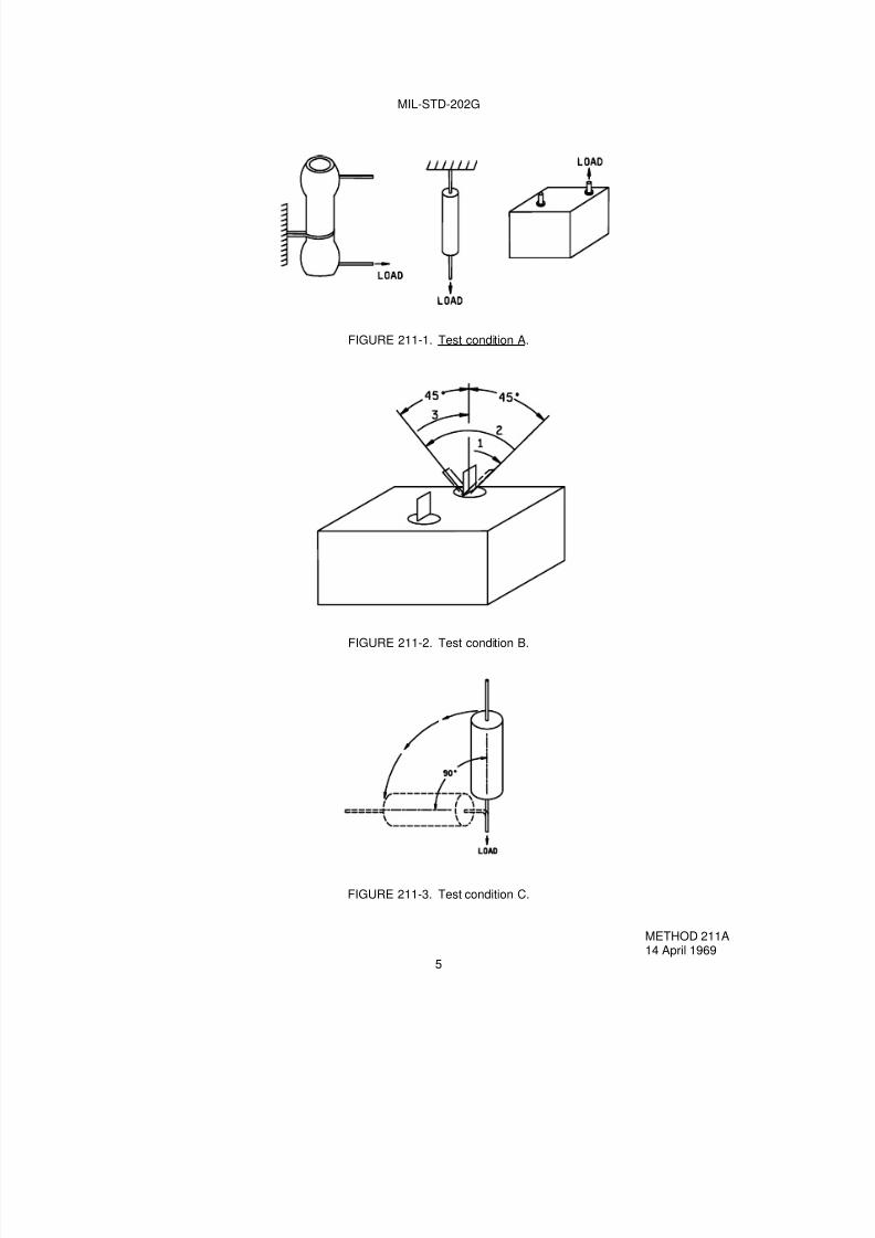
7/29/2019 TEST METHOD STANDARD ELECTRONIC AND ELECTRICAL COMPONENT PARTS
http://slidepdf.com/reader/full/test-method-standard-electronic-and-electrical-component-parts 121/191
MIL-STD-202G
FIGURE 211-1. Test condition A.
FIGURE 211-2. Test condition B.
FIGURE 211-3. Test condition C.
METHOD 211A14 April 1969
5

7/29/2019 TEST METHOD STANDARD ELECTRONIC AND ELECTRICAL COMPONENT PARTS
http://slidepdf.com/reader/full/test-method-standard-electronic-and-electrical-component-parts 122/191
MIL-STD-202G
STEP 1. Bend lead with fingers, over rounded edge of metal plate as shown in (a).STEP 2. Center component part in chuck; secure lead in clamp as shown in (b).STEP 3. Rotate chuck part through 360°at a rate of approximately 5 seconds per 360°rotation. Successive
rotations shall be in alternate directions. A total of three such 360° rotations shall be performed. Duringthis test, the chuck shall rotate around an axis which is fixed with respect to the padded clamp, or viceversa. The chuck shall have no appreciable end play during rotation.
NOTE: Metric equivalents are in parentheses.
FIGURE 211-4. Test condition D.
METHOD 211A14 April 1969
6
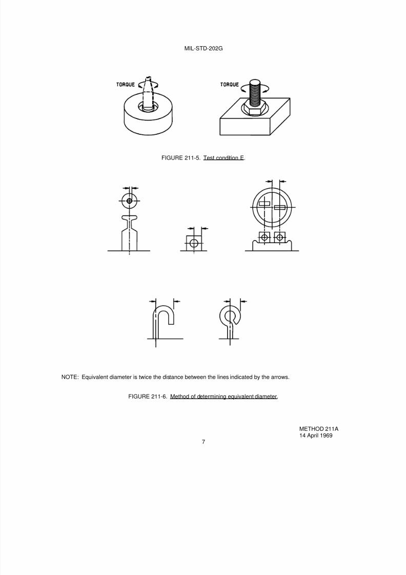
7/29/2019 TEST METHOD STANDARD ELECTRONIC AND ELECTRICAL COMPONENT PARTS
http://slidepdf.com/reader/full/test-method-standard-electronic-and-electrical-component-parts 123/191
MIL-STD-202G
FIGURE 211-5. Test condition E.
NOTE: Equivalent diameter is twice the distance between the lines indicated by the arrows.
FIGURE 211-6. Method of determining equivalent diameter.
METHOD 211A14 April 1969
7

7/29/2019 TEST METHOD STANDARD ELECTRONIC AND ELECTRICAL COMPONENT PARTS
http://slidepdf.com/reader/full/test-method-standard-electronic-and-electrical-component-parts 124/191
7/29/2019 TEST METHOD STANDARD ELECTRONIC AND ELECTRICAL COMPONENT PARTS
http://slidepdf.com/reader/full/test-method-standard-electronic-and-electrical-component-parts 125/191
MIL-STD-202G
METHOD 212A
ACCELERATION
1. PURPOSE. This test is performed for the purpose of determining the effects of acceleration stress oncomponent parts, and to verify the ability of the component parts to operate properly during exposure to accelerationstress such as would be experienced in aircraft, missiles, etc.
2. APPARATUS. Unless otherwise specified, the acceleration test apparatus shall be the centrifuge-type and shallbe capable of subjecting the test specimen to the value of acceleration (g’s) as specified in 3. The accelerationgradient across the specimen shall not exceed 15 percent of the specified g level.
2.1 Mounting accessories. Provisions shall be made to permit mounting by the normal means so that thespecimen can be tested in both directions, 180 degrees apart, of each of three mutually perpendicular axes, unlessotherwise specified. Parts with axial terminations weighing less than 0.5 ounce shall be soldered to stand-offterminals, leaving a distance of 0.2 inch to 0.3 inch from the point of emergence to the terminals. Parts weighing 0.5ounce and more shall be clamped so as to avoid any stress on the leads. Parts having radial leads and those ofunusual mass distribution shall be mounted as specified in the individual specification. If loading, actuating, orpolarizing currents are required, they shall be specified. Provisions shall be made for all electrical connections to be
secure.
3. PROCEDURE. The specimen under test shall be mounted in a rigid position as specified in 2.1 and shall besubjected to one of the following test conditions, as specified in the individual specification:
3.1 Test condition A. The specimen shall be subjected to 5 minutes acceleration of the specified "g" level in bothdirections of each of three mutually perpendicular axes for a total of 30 minutes at either 20, 50, or 100g level. Theacceleration measured at any point of the component part shall not exceed 15 percent of the "g" level.
3.2 Test condition B. The specimen shall be subjected for 1 minute at nominally 10,000 or 20,000g in the directionas specified in the individual specification. The rate of acceleration shall be increased smoothly from zero to thespecified value in not less than 20 seconds. The rate of acceleration shall be decreased smoothly to zero in not lessthan 20 seconds.
3.3 Test condition C. The specimen shall be subjected to the value of acceleration specified in the individual
specification for 10 minutes in both directions of each of three mutually perpendicular axes. The acceleration shall beincreased smoothly from zero to the specified value in approximately 2 minutes. The acceleration shall be decreasedsmoothly to zero in not less than 2 minutes.
4. MEASUREMENTS. The measurements made before, during, or after the test shall be as specified.
METHOD 212A18 April 1973
1 of 2

7/29/2019 TEST METHOD STANDARD ELECTRONIC AND ELECTRICAL COMPONENT PARTS
http://slidepdf.com/reader/full/test-method-standard-electronic-and-electrical-component-parts 126/191
MIL-STD-202G
5. SUMMARY. The following details are to be specified in the individual specification:
a. Mounting of specimens (see 2.1).
b. Electrical loading if applicable (see 2.1).
c. Test condition letter (see 3).
d. If test condition A is specified, the value of g (see 3.1).
e. If test condition B is specified, the directions of application of acceleration and value of g (see 3.2).
f. If test condition C is specified, the value of acceleration (see 3.3).
g. Measurements (see 4).
METHOD 212A18 April 1973
2

7/29/2019 TEST METHOD STANDARD ELECTRONIC AND ELECTRICAL COMPONENT PARTS
http://slidepdf.com/reader/full/test-method-standard-electronic-and-electrical-component-parts 127/191
MIL-STD-202G
METHOD 213B
SHOCK (SPECIFIED PULSE)
1. PURPOSE. This test is conducted for the purpose of determining the suitability of component parts andsubassemblies of electrical and electronic components when subjected to shocks such as those which may beexpected as a result of rough handling, transportation and military operations. This test differs from other shock testsin this standard in that the design of the shock machine is not specified, but the half-sine and sawtooth shock pulsewaveforms are specified with tolerances. The frequency response of the measuring system is also specified withtolerances.
2. APPARATUS.
2.1 Shock machine. The shock machine utilized shall be capable of producing the specified input shock pulse asshown on figures 213-1 or 213-2, as applicable. The shock machine may be of the free fall, resilient rebound,nonresilient, hydraulic, compressed gas, or other activating types.
2.1.1 Shock machine calibration. The actual test item, or a dummy load which may be either a rejected item or arigid dummy mass, may be used to calibrate the shock machine. (When a rigid dummy mass is used, it shall have
the same center of gravity and the same mass as that of the test item and shall be installed in a manner similar tothat intended for the test item.) The shock machine shall then be calibrated for conformance with the specifiedwaveform. Two consecutive shock applications to the calibration load shall produce waveforms which fall within thetolerance envelope given on figures 213-1 or 213-2. The calibration load shall then be removed and the shock testperformed on the actual test item. If all conditions remain the same, other than the substitution of the test item for thecalibration load, the calibration shall then be considered to have met the requirements of the waveform.
NOTE: It is not implied that the waveform generated by the shock machine will be the same when the actual testitem is used instead of the calibration load. However, the resulting waveform is considered satisfactory if thewaveform with the calibration load was satisfactory.
2.2 Instrumentation. In order to meet the tolerance requirements of the test procedure, the instrumentation used tomeasure the input shock shall have the characteristics specified in the following paragraphs.
2.2.1 Frequency response. The frequency response of the complete measuring system, including the transducer
through the readout instrument, shall be as specified by figure 213-3.
2.2.1.1 Frequency response measurement of the complete instrumentation. The transducer-amplifier-recordingsystem can be calibrated by subjecting the transducer to sinusoidal vibrations of known frequencies and amplitudesfor the required ranges so that the overall sensitivity curve can be obtained. The sensitivity curve, normalized to beequal to unity at 100 Hz, should then fall within the limits given on figure 213-3.
2.2.1.2 Frequency response measurement of auxiliary equipment. If calibration factors given for the accelerometerare such that when used with the associated equipment it will not affect the overall frequency response, then thefrequency response of only the amplifier-recording system may be determined. This shall be determined in thefollowing manner: Disconnect the accelerometer from the input terminals of its amplifier. Connect a signal voltagesource to these terminals. The impedance of the signal voltage source as seen by the amplifier shall be made as theimpedance of the accelerometer and associated circuitry as seen by the amplifier. With the frequency of the signalvoltage set at 100 Hz, adjust the magnitude of the voltage to be equal to the product of the accelerometer sensitivityand the acceleration magnitude expected during test conditions. Adjust the system gain to a convenient value.Maintain a constant input voltage and sweep the input frequency over the range from 1.0 to 9,000 Hz, or 4 to 25,000Hz, as applicable, depending on duration of pulse. The frequency response in terms of dB shall be within the limitsgiven on figure 213-3.
METHOD 213B16 April 1973
1 of 7
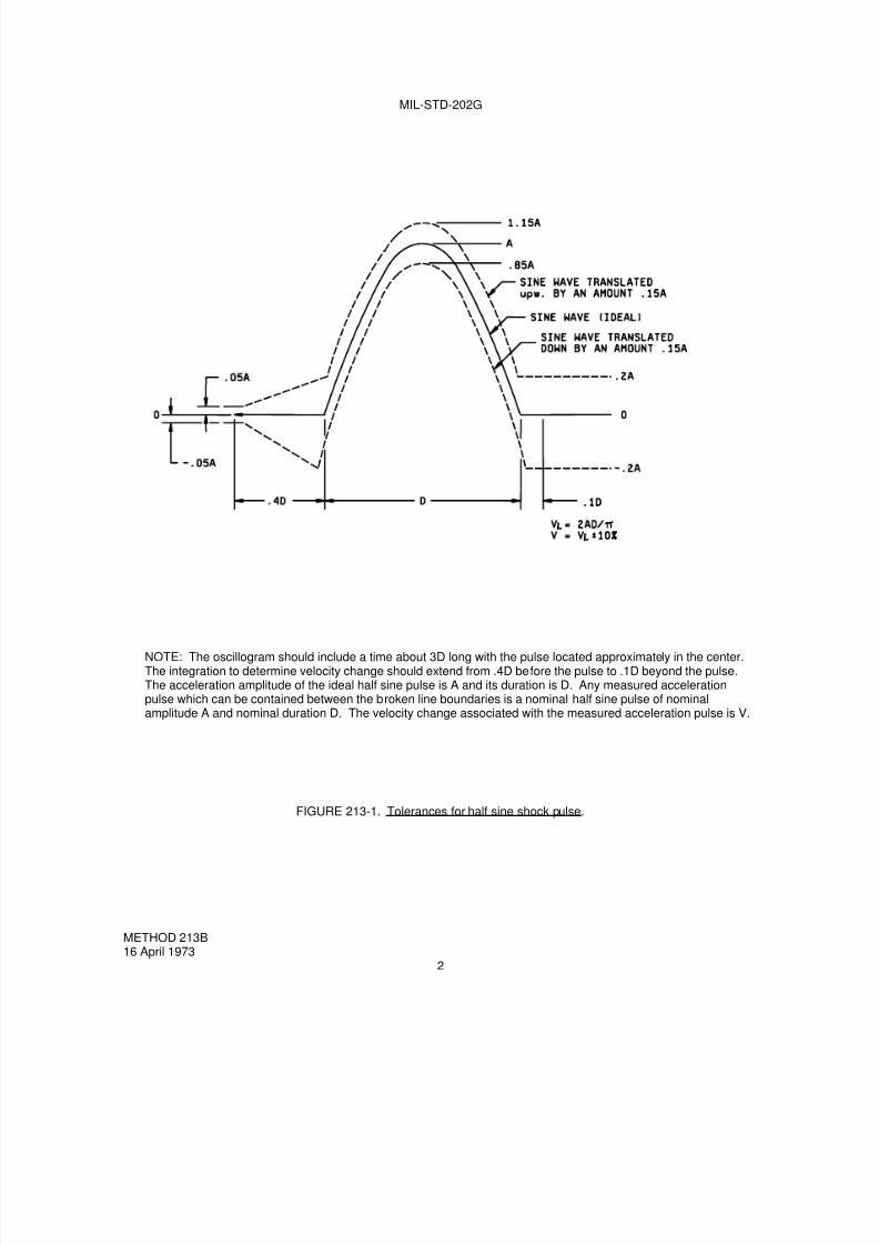
7/29/2019 TEST METHOD STANDARD ELECTRONIC AND ELECTRICAL COMPONENT PARTS
http://slidepdf.com/reader/full/test-method-standard-electronic-and-electrical-component-parts 128/191
MIL-STD-202G
NOTE: The oscillogram should include a time about 3D long with the pulse located approximately in the center.The integration to determine velocity change should extend from .4D before the pulse to .1D beyond the pulse.The acceleration amplitude of the ideal half sine pulse is A and its duration is D. Any measured accelerationpulse which can be contained between the broken line boundaries is a nominal half sine pulse of nominalamplitude A and nominal duration D. The velocity change associated with the measured acceleration pulse is V.
FIGURE 213-1. Tolerances for half sine shock pulse.
METHOD 213B16 April 1973
2

7/29/2019 TEST METHOD STANDARD ELECTRONIC AND ELECTRICAL COMPONENT PARTS
http://slidepdf.com/reader/full/test-method-standard-electronic-and-electrical-component-parts 129/191
MIL-STD-202G
NOTE: The oscillogram should include a time about 3D long with the pulse approximately in the center. Theintegration to determine the velocity change should extend from .4D before the pulse to .1D beyond the pulse.The peak acceleration magnitude of the sawtooth pulse is P and its duration is D. Any measured accelerationpulse which can be contained between the broken line boundaries is a nominal terminal-peak sawtooth pulse ofnominal peak value, P, and nominal duration, D. The velocity change associated with the measured accelerationpulse is V.
FIGURE 213-2. Tolerances for terminal-peak sawtooth shock pulse.
METHOD 213B16 April 1973
3

7/29/2019 TEST METHOD STANDARD ELECTRONIC AND ELECTRICAL COMPONENT PARTS
http://slidepdf.com/reader/full/test-method-standard-electronic-and-electrical-component-parts 130/191
MIL-STD-202G
Duration of pulse(ms) Low frequencycut-off (Hz) High frequencycut-off (kHz)-1 dB
Frequency beyond whichthe response may riseabove +1 dB (kHz)
-1dB -10dB
3
<33
>3
1616
4
441
1555
402525
FIGURE 213-3. Tolerance limits for measuring system frequency response.
METHOD 213B16 April 1973
4
7/29/2019 TEST METHOD STANDARD ELECTRONIC AND ELECTRICAL COMPONENT PARTS
http://slidepdf.com/reader/full/test-method-standard-electronic-and-electrical-component-parts 131/191
MIL-STD-202G
2.2.2 Transducer. The fundamental resonant frequency of the accelerometer shall be greater than 30,000 Hz,when the accelerator is employed as the shock sensor.
2.2.3 Transducer calibration. Transducers shall be calibrated in accordance with ASA STD S2.2-1959. Theaccuracy of the calibration method shall be at least ±5 percent over the frequency range of 2 to 5,000 Hz. Theamplitude of the transducer being calibrated shall also be ±5 percent over the frequency range of 4 to 5,000 Hz.
2.2.4 Linearity. The signal level of the system shall be chosen so that the acceleration pulse operates over thelinear portion of the system.
2.2.5 Transducer mounting. When conformance to 2.3 is required, the monitoring transducer shall be rigidlysecured and located as near as possible to an attachment point of the specimen but not on the specimen itself.
2.3 Application of shock measuring instrumentation. Shock measuring instrumentation shall be utilized todetermine that the correct input shock pulse is applied to the test specimen. This is particularly important where amulti-specimen test is made. Generally, the shock pulse should be monitored whenever there is a change in the testsetup, such as a different test fixture, different component (change in physical characteristics), different weight,different shock pulse (change in pulse shape, intensity, or duration) or different shock machine characteristics. It is
not mandatory that each individual shock be monitored, provided that the repeatability of the shock application asspecified in 2.1.1 has been established.
3. SHOCK PULSES. Two types of shock pulses, a half-sine shock pulse and a sawtooth shock pulse, arespecified. The pulse shape and tolerances are shown on figures 213-1 and 213-2, respectively. For single degree offreedom systems, a sawtooth shock pulse can be assumed to have a damage potential at least as great as that of thehalf-sine pulse if the shock spectrum of the sawtooth pulse is everywhere at least as great as that of the half-sinepulse. This condition will exist for two such pulses of the same duration if over most of the spectrum the accelerationpeak value of the sawtooth pulse is 1.4 times the acceleration peak value of the half-sine pulse.
3.1 Half-sine shock pulse. The half-sine shock pulse shall be as indicated on figure 213-1. The velocity change ofthe pulse shall be within ±10 percent of the velocity change of the desired shock pulse. The velocity change may bedetermined either by direct measurement, indirectly, or by integrating (graphically or electrically) the area (fairedacceleration pulse may be used for the graphical representation) under the measured acceleration pulse. For half-sine acceleration pulses of less than 3 milliseconds duration the following tolerances should apply: The faired
maximum value of the measured pulse shall be within ±20 percent of the specified ideal pulse amplitude, its durationshall be within ±15 percent of the specified ideal pulse duration, and the velocity change associated with the
measured pulse shall be within ±10 percent of V i = 2AD/ π. See figure 213-1. The measured pulse will then beconsidered a nominal half-sine pulse with a nominal amplitude and duration equal to respective values of thecorresponding ideal half-sine pulse. The duration of the measured pulse shall be taken as Dm = D(.1A)/.94; whereD(.1A) is the time between points at .1A for the faired measured acceleration pulse.
3.1.1 The ideal half-sine pulse. An ideal half-sine acceleration pulse is given by the solid curve. See figure 213-1.The measured acceleration pulse must lie within the boundaries given by the broken lines. In addition, the actualvelocity change of the shock must be within 10 percent of the ideal velocity change. The actual velocity change canbe determined by direct measurements, or from the area under the measured acceleration curve. The ideal velocity
change is equal to Vi = 2AD/ π; where A is the acceleration amplitude and D is the pulse duration of the ideal pulse.
METHOD 213B16 April 1973
5

7/29/2019 TEST METHOD STANDARD ELECTRONIC AND ELECTRICAL COMPONENT PARTS
http://slidepdf.com/reader/full/test-method-standard-electronic-and-electrical-component-parts 132/191
MIL-STD-202G
3.2 Sawtooth shock pulse. The sawtooth pulse shall be as indicated on figure 213-2. The velocity change of thefaired measured pulse shall be within ±10 percent of the velocity change of the ideal pulse.
3.2.1 The ideal terminal-peak sawtooth. An ideal terminal-peak sawtooth acceleration pulse is given by the solidline. See figure 213-2. The measured acceleration pulse must be within the boundaries given by the broken lines. Inaddition, the actual velocity change of the shock pulse must be within 10 percent of the ideal value. The actualvelocity change can be determined from direct measurements, or from the area under the measured accelerationcurve. The ideal velocity change is equal to Vi = PD/2; where P is the peak value of acceleration, and D is the pulseduration.
4. PROCEDURE. The test specimen shall be mounted as specified in the component specification. Wheneverpossible, the test load shall be distributed uniformly on the test platform in order to minimize the effects of unbalancedloads.
4.1 Basic design test. Three shocks in each direction shall be applied along the three mutually perpendicular axesof the test specimen (18 shocks). If the test specimen is normally mounted on vibration isolators, the isolators shallbe functional during the test. The specified test pulse (half-sine or sawtooth pulse) shall be in accordance withfigures 213-1 and 213-2, respectively, and shall have a duration and peak value in accordance with one of the test
conditions of table 213-1.
TABLE 213-1. Test condition values.
Testcondition
Peak value(g’s)
Normalduration (D) (ms)
Waveform Velocitychange (Vi) ft/sec
ABCDEFGHIJK
5075
100500
1,0001,500
5075
1003030
116610.50.5
1166
1111
Half-sineHalf-sineHalf-sineHalf-sine 1/ 2/ 3/ Half-sine 1/ 2/ 3/ Half-sine 1/ 2/ 3/ Sawtooth 2/ Sawtooth 2/ Sawtooth 2/ Half-sineSawtooth
11.39.2
12.310.210.215.48.87.29.76.85.3
1/ For half-sine shock pulses of less than 3 milliseconds duration, it is not required that the envelopefall within the tolerances specified on figure 213-1. The faired amplitude of the measured pulseshall be within ±20 percent of the ideal amplitude. The measured duration shall be within ±15percent of the specified amplitude duration. The velocity change of the faired measured pulse shallbe within ±10 percent of the ideal pulse. The duration of the pulse shall be measured at the 0.1Apoint on the pulse. The duration of the pulse shall be the duration measured at the 0.1A pointdivided by .94. Test conditions D, E, and F are principally applicable to semiconductors.
2/ Test conditions G, H, and I (sawtooth) waveforms are preferred, except for semi- conductors, forwhich test conditions D, E, and F (half-sine) are preferred.
3/ For test condition D. Where the weight of multi-specimen and fixtures exceeds 150 pounds, thereis a question as to whether the shock pulse is properly transmitted to all specimens. Dueconsideration should be given to the design of the test fixture to assure the proper shock input toeach specimen. This also applies to test conditions E and F except that where the weight of themulti-specimen and fixtures exceeds 25 pounds.
METHOD 213B16 April 1973
6

7/29/2019 TEST METHOD STANDARD ELECTRONIC AND ELECTRICAL COMPONENT PARTS
http://slidepdf.com/reader/full/test-method-standard-electronic-and-electrical-component-parts 133/191

7/29/2019 TEST METHOD STANDARD ELECTRONIC AND ELECTRICAL COMPONENT PARTS
http://slidepdf.com/reader/full/test-method-standard-electronic-and-electrical-component-parts 134/191
7/29/2019 TEST METHOD STANDARD ELECTRONIC AND ELECTRICAL COMPONENT PARTS
http://slidepdf.com/reader/full/test-method-standard-electronic-and-electrical-component-parts 135/191

7/29/2019 TEST METHOD STANDARD ELECTRONIC AND ELECTRICAL COMPONENT PARTS
http://slidepdf.com/reader/full/test-method-standard-electronic-and-electrical-component-parts 136/191
MIL-STD-202G
2.2 Monitoring. Monitoring involves measurements of the vibration excitation and of the test item performance.When required in the individual specification, the specimen may be monitored during the test. The details of themonitoring circuit, including the method and points of connection to the specimen, shall be specified.
2.2.1 Vibration input. The vibration magnitude shall be monitored on a vibration machine, on mounting fixtures, atlocations that are as near as practical to the test item mounting points. When the vibration input is measured at morethan one point, the minimum input vibration shall normally be made to correspond to the specified test curve (seefigures 214-1 and 214-2). For massive test items and fixtures, and for large force exciters or multiple vibrationexciters, the input-control value may be an average of the average magnitudes of three or more inputs. Accelerationsin the transverse direction, measured at the test item attachment points, shall be limited to 100 percent of the appliedvibration. The individual specification shall specify the number and location of the test points.
3. METHOD OF MOUNTING. The specimens shall be mounted in accordance with the instructions in theindividual specifications. The orientation of the specimen or direction(s) of the applied vibration motion shall be asspecified. Any special test fixtures or jigs required to run the test shall be as specified in sufficient detail in theindividual specification to assure reproducibility of the input motion applied to the specimen. These details shallinclude the dimensions, the materials, temper, etc., as applicable.
4. PROCEDURE. The specimen, or substitute equivalent mass, shall be mounted in accordance with 3 and themonitoring equipment attached, if applicable, in accordance with 2.2. The vibration machine shall then be operatedand equalized or compensated to deliver the required frequencies and intensities conforming to the curves specifiedtest condition I, figure 214-1, or test condition II, figure 214-2 (see 2.1). If the order of application of the differentdirections is critical, it also shall be specified in the individual specification. The specimen shall then be subjected tothe vibration specified by the test condition letter (see tables 214-I and 214-II) for the duration as specified in theindividual specification:
3-minutes; 15-minutes; 1-1/2 hours; or, 8-hours;
In each of three mutually perpendicular directions, and in the order specified as applicable. The measurements madebefore, during, and after the test shall be made in accordance with 5 and if the specimen shall be monitored duringthe test, the details shall be as specified in 2.2.
5. MEASUREMENTS. Measurements shall be performed before, during, and after the test as specified in the
individual specification.
6. SUMMARY. The following details are to be specified in the individual specification:
a. Monitoring instrumentation, if applicable (see 2.2).
b. The number and location of test points (see 2.2.1).
c. Method of mounting and orientation (see 3).
d. Test condition (I or II); letter (A-K); and duration of test (3-minutes, 15-minutes, 1-1/2 hours, or 8-hours)(see 4).
e. Order of application of vibration direction, if applicable (see 4).
f. Measurements before, during, and after test (see 5).
METHOD 214A28 March 1984
2
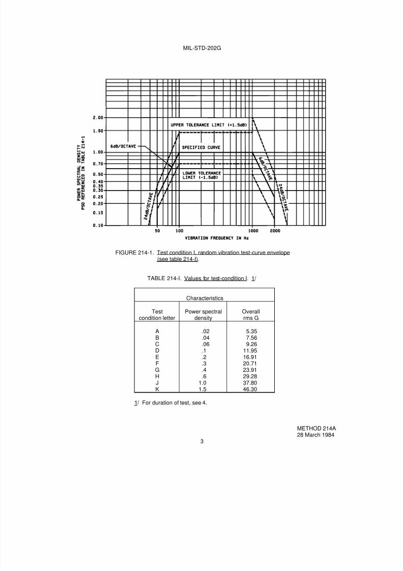
7/29/2019 TEST METHOD STANDARD ELECTRONIC AND ELECTRICAL COMPONENT PARTS
http://slidepdf.com/reader/full/test-method-standard-electronic-and-electrical-component-parts 137/191
MIL-STD-202G
FIGURE 214-1. Test condition I, random vibration test-curve envelope(see table 214-I).
TABLE 214-I. Values for test-condition I. 1/
Characteristics
Testcondition letter
Power spectraldensity
Overallrms G
ABCDEFGHJK
.02
.04
.06
.1
.2
.3
.4
.61.01.5
5.357.569.26
11.9516.9120.7123.9129.2837.8046.30
1/ For duration of test, see 4.
METHOD 214A28 March 1984
3

7/29/2019 TEST METHOD STANDARD ELECTRONIC AND ELECTRICAL COMPONENT PARTS
http://slidepdf.com/reader/full/test-method-standard-electronic-and-electrical-component-parts 138/191
MIL-STD-202G
FIGURE 214-2. Test condition II, random vibration test-curve envelope(see table 214-II).
TABLE 214-II. Values for test-condition II. 1/
Characteristics
Testcondition letter
Power spectraldensity
Overallrms G
ABCDEFG
HJK
.02
.04
.06
.1
.2
.3
.4
.61.01.5
6.218.78
10.7613.8919.6424.0627.78
34.0243.9253.79
1/ For duration of test, see 4.
METHOD 214A28 March 1984
4
7/29/2019 TEST METHOD STANDARD ELECTRONIC AND ELECTRICAL COMPONENT PARTS
http://slidepdf.com/reader/full/test-method-standard-electronic-and-electrical-component-parts 139/191
MIL-STD-202G
METHOD 215K
RESISTANCE TO SOLVENTS
1. PURPOSE. The purpose of this test is as follows:
a. To verify that markings or color coding will not become illegible or discolored on the parts (including printedwiring boards) when subjected to solvents and processes normally used to clean solder-flux, fingerprints,and other contaminants from printed-wiring and terminal-board assemblies, etc.
b. To verify that component protective coatings and encapsulant materials are not degraded to the point whereelectrical or mechanical integrity is disturbed when subjected to solvents and processes normally used toclean solder flux, fingerprints, and other contaminants from printed-wiring and terminal-board assemblies,etc.
1.1 Formulation of solvents. The formulation of solvents is considered typical and representative of the solventsused in printed wiring assembly processing of electronic components. Processing conditions are representative ofprocesses used for printed wiring assembly.
1.2 Checks for conflicts. When this test is referenced, care should be exercised to assure that conflictingrequirements, as far as the properties of the specified finishes and markings are concerned, are not invoked.
2. MATERIALS
2.1 Solvent solutions. The solvent solutions used in this test shall consist of the following (see table I forsummary).
a. A mixture consisting of the following:
1. One part by volume of isopropyl alcohol, American Chemical Society (ACS) reagent grade, orisopropyl alcohol in accordance with TT-I-735, grade A or B, and
2. Three parts by volume of mineral spirits in accordance with MIL-PRF-680, type I, or three parts byvolume of a mixture of 80 percent by volume of kerosene and 20 percent by volume ethylbenzene.
b. This solvent has been deleted. When a suitable replacement solvent has been determined, it will beadded as solution b.
c. A terpene defluxer consisting of a minimum of 90 percent d-limonene and 10 percent surfactant. 1/
d. A mixture consisting of the following:
1. Forty-two parts by volume water, 1 megohm-cm minimum resistivity.
2. One part by volume of propylene glycol monomethyl ether (glycol ether PM, 1-methoxy-2-propanol).
3. One part by volume of monoethanolamine. 2/
2.1.1 Solvent solutions, safety aspects. Solvent solutions listed in 2.1a through 2.1d exhibit some potential for healthand safety hazards. Safety precautions as listed in the appropriate manufacturers material safety data sheet shall beobserved.
1/ A commonly used terpene defluxer is BIOACT EC-7R. "BIOACT" is a registered Trademark of Petroferm INC; "EC-7 and EC-7R" are trademarks of Petroferm INC.2/ Normal safety precaution for handling this solution (e.g., same as those for diluted ammonium hydroxide) based on O.S.H.A.rules for monoethanolamine.
METHOD 215K 8 February 2002
1 of 4

7/29/2019 TEST METHOD STANDARD ELECTRONIC AND ELECTRICAL COMPONENT PARTS
http://slidepdf.com/reader/full/test-method-standard-electronic-and-electrical-component-parts 140/191
MIL-STD-202G
2.2 Vessel. The vessel for solvent immersion shall be a container made of non-reactive material and of sufficientsize to permit complete immersion of the specimens in the solvent solutions specified in 2.1.
2.3 Brush. The brush shall be a toothbrush with a handle made of a non-reactive material. The brush shall havethree or four long rows, 1 and 1/8 ±1/8 inch in length, of hard bristles. Each row shall contain eight to twelve tufts, thefree ends of which shall lie substantially in the same plane. The brush shall be used with a single solvent and whenthere is any evidence of softening, bending, wear, or loss of bristles, it shall be discarded.
3. PROCEDURE
3.1 Procedure. The specimens subjected to this test shall be divided into three groups of approximately equal size.
a. The first group shall be exposed to the solution specified in 2.1a.
The solution shall be maintained at a temperature of 25°C ±5°C. The specimens shall be completely immersedfor 3 minutes +0.5, -0 minutes in the specified solution contained in the vessel specified in 2.2. Immediatelyfollowing immersion, each specimen shall be tested as follows: The bristle portion of the brush, specified in 2.3,shall be dipped in the solution until wetted and the specimen shall be brushed with normal hand pressure
(approximately 2 to 3 ounce force applied normal to the surface) for ten strokes on the portion of the specimenwhere marking has been applied. The brush stroke shall be directed in a forward direction across the surface ofthe specimen being tested. Immediately after brushing, the procedure shall be repeated two more times, for atotal of three immersions, followed by brushing. After completion of the third immersion and brushing, thespecimens shall be air-blown dry. The specimens shall be inspected in accordance with 4.1 and 4.2 todetermine the extent, if any, of deterioration that has occurred.
b. This solvent solution has been deleted.
c. The second group shall be exposed to the solution specified in 2.1c.
The solution shall be maintained at a temperature of 25°C ±5°C. The specimens shall be completely immersedfor 3 minutes +0.5, -0 minutes in the specified solution contained in the vessel specified in 2.2. Immediatelyfollowing immersion, each specimen shall be tested as follows: The bristle portion of the brush, specified in 2.3,shall be dipped in the solution until wetted and the specimen shall be brushed with normal hand pressure(approximately 2 to 3 ounce force applied normal to the surface) for ten strokes on the portion of the specimenwhere marking has been applied. The brush stroke shall be directed in a forward direction across the surface ofthe specimen being tested. Immediately after brushing, the procedure shall be repeated two more times, for atotal of three immersions, followed by brushing. After completion of the third immersion and brushing, the
specimens shall be rinsed in approximately 25°C water and all surfaces air-blown dry. The specimens shall beinspected in accordance with 4.1 and 4.2 to determine the extent, if any, of deterioration that has occurred.
d. The third group shall be exposed to the solution specified in 2.1d.
The solution shall be maintained at a temperature of 63°C to 70°C. The specimens shall be completelyimmersed for 3 minutes +0.5, -0 minutes in the specified solution contained in the vessel specified in 2.2.Immediately following immersion, each specimen shall be tested as follows: The bristle portion of the brush,specified in 2.3, shall be dipped in the solution until wetted and the specimen shall be brushed with normal handpressure (approximately 2 to 3 ounce force applied normal to the surface) for ten strokes on the portion of the
specimen where marking has been applied. The brush stroke shall be directed in a forward direction across thesurface of the specimen being tested. Immediately after brushing, the procedure shall be repeated two moretimes, for a total of three immersions, followed by brushing. After completion of the third immersion and
brushing, the specimens shall be rinsed in approximately 25°C water and all surfaces air-blown dry. Thespecimens shall be inspected in accordance with 4.1 and 4.2 to determine the extent, if any, of deterioration thathas occurred.
METHOD 215K8 February 2002
2

7/29/2019 TEST METHOD STANDARD ELECTRONIC AND ELECTRICAL COMPONENT PARTS
http://slidepdf.com/reader/full/test-method-standard-electronic-and-electrical-component-parts 141/191
MIL-STD-202G
3.2 Optional exposure procedure for the third group. The test specimens shall be located on a test surface ofknown area which is located 6 ±1 inches (15 ±2.5 centimeters) below a spray nozzle which discharges .16 ±.005 gpm(0.62 ±0.02 liters per minute) of solution per in
2(6.5 square centimeters) of surface area at a pressure of 20 ±5 lbs/in
2
(138 ±34 kilopascal). The solvent shall be held at a temperature range of 63°C to 70°C. The specimens shall besubjected to this spray for a period of 10 minutes. After completion of the spray exposure, the specimens shall bethoroughly rinsed in water and all surfaces air-blown dry and inspected in accordance with 4.1 and 4.2 to determinethe extent, if any, of deterioration that has occurred. If this optional procedure is specified, brushing of the samples inthe third group is not required. If a conflict arises from the use of the spray option, the brush method of 3.1d shall beused as the referee procedure. The measurements shown in parentheses are not exact equivalents and are shownfor convenience only.
3.3 Immersion test for components with marking protected by a sleeve material. Components with a protectivesleeve shall be divided into three groups as specified in 3, and each group shall be subjected to testing using the
solution defined for that group. Each solution shall be maintained at a temperature of 25°C ±5°C, except the solution
in 2.1d shall be maintained at a temperature of 63°C to 70°C. The specimens shall be completely immersed for 3minutes +.5, -0 minutes in the specified solution contained in the vessel specified in 2.2. Immediately followingimmersion, each specimen shall be tested as follows: The bristle portion of the brush specified in 2.3 shall be dippedin the solution until wetted and the specimen shall be brushed with normal hand pressure (approximately 2 to 3 ounce
force applied normal to the surface) for ten strokes on the sleeve directly above the area of the marking. Immediatelyafter brushing, the procedure shall be repeated two more times for a total of three immersions followed by brushing.The brush stroke shall be directed in a forward direction across the sleeve area above the marking. After completionof the third immersion and brushing, the specimens shall be air-blown dry. The specimens shall be inspected inaccordance with 4.1 and 4.2 to determine the extent, if any, of deterioration that has occurred, including the sleeve.
3.4 Open construction parts and parts not intended for PCB mounting. Parts of open construction which aresusceptible to internal damage by immersion in solvents and parts not intended for mounting on printed circuitboards, shall be divided into three groups as specified in 3, and each group shall be subjected to testing using the
solution defined for that group. Each solution shall be maintained at a temperature of 25°C ±5°C, except for the
solution in 2.1d, which shall be maintained at a temperature range of 63°C to 70°C, and shall be contained in thevessel specified in 2.2. Each group shall be tested as follows: The bristle portion of the brush specified in 2.3 shallbe immersed in the respective solution for each group until wetted. The marking area of the specimen to be testedshall then be immediately brushed with normal hand pressure (approximately 2 to 3 ounce force applied normal to thesurface) for ten strokes on the portion of the specimen where marking has been applied (test area not to exceed one-half inch square). The brush stroke shall be directed in a forward direction across the marked surface. This test shallbe repeated twice for a total of three times for each specimen. The specimens shall then be inspected in accordancewith 4.1 and 4.2 to determine the extent of deterioration, if any.
4. EXAMINATION AND MEASUREMENTS
4.1 Marking resistance to solvents. After subjection to the test, any specified markings which are missing in wholeor in part, faded, smeared, blurred, or shifted (dislodged) to the extent that they cannot be readily identified from adistance of at least 6 inches with normal room lighting without the aid of magnification or with a viewer having amagnification no greater than 3X shall constitute failure.
4.2 Component protective coating, encapsulation material and sleeve material resistance. After subjection to thetest, the specimen shall be examined for cracks, separations, crazing, swelling, softening, and degradation of bodymaterial, end caps and seals if present, or any other damage or degradation that has occurred due to solvent
exposure and which effects the mechanical integrity or reliability shall constitute a failure. The examination shall bemade with a viewer having a magnification of 10X maximum.
METHOD 215K 8 February 2002
3

7/29/2019 TEST METHOD STANDARD ELECTRONIC AND ELECTRICAL COMPONENT PARTS
http://slidepdf.com/reader/full/test-method-standard-electronic-and-electrical-component-parts 142/191
MIL-STD-202G
5. SUMMARY. The following details are to be specified in the individual specification:
a. The number of specimens to be tested.
b. Optional procedure for the third group allowed (see 3.2).
TABLE I. Summary table for resistance to solvents.
Solvent 1 Solvent 2 Solvent 3 Solvent 4
1 part (by volume) of isopropylalcohol (ACS)reagent grade or TT-I-735,grade A or B and 3 parts (byvolume) of mineral spirits perMil-Prf-680, type I, or three parts (by volume) of amixture of 80% (by volume) of
kerosene and 20%(by volume) ethylbenzene.
This solvent hasbeen deleted.
Terpene defluxer 42 parts (by volume) ofwater1 part (by volume) ofpropylene glycolmonomethyl ether1 part (by volume) ofmonoethanolamine
Immersion 3 +.5, -0 minutes,
25°C ±5°C
Immersion 3 +.5, -0
minutes, 25°C, ±5°C
Immersion 3 +.5, -0
minutes, 63°C to 70°C
Brush 10 strokes (wet bristle)2 to 3 oz.
Brush 10 strokes (wetbristle) 2 to 3 oz.
Brush 10 strokes (wetbristle) 2 to 3 oz.
Immersion 3 +.5, -0 minutes,
25°C ±5°C.
Immersion 3 +.5, -0
minutes, 25°C ±5°C.
Immersion 3 +.5, -0
minutes, 63°C to 70°C.
Brush 10 strokes (wet bristle)
2 to 3 oz.
Brush 10 strokes (wet
bristle) 2 to 3 oz.
Brush 10 strokes (wet
bristle) 2 to 3 oz.
Immersion 3 +.5, -0 minutes,
25°C ±5°C.
Immersion 3 +.5, -0
minutes, 25°C ±5°C.
Immersion 3 +.5, -0
minutes, 63°C to 70°C.
Brush 10 strokes (wet bristle)2 to 3 oz.
Brush 10 strokes (wetbristle) 2 to 3 oz.
Brush 10 strokes (wetbristle) 2 to 3 oz.
Rinse in water Rinse in water.
Air blow dry. Air blow dry Air blow dry.
Inspect at 3X maximum formarking.Inspect at 10X maximum forpart damage.
Inspect at 3X maximumfor marking.Inspect at 10X maximumfor part damage.
Inspect at 3X maximumfor marking.Inspect at 10X maximumfor part damage.
METHOD 215K8 February 2002
4

7/29/2019 TEST METHOD STANDARD ELECTRONIC AND ELECTRICAL COMPONENT PARTS
http://slidepdf.com/reader/full/test-method-standard-electronic-and-electrical-component-parts 143/191
MIL-STD-202G
METHOD 216
RESISTANCE TO SOLDER WAVE HEAT
NOTICE
Method 216 has been canceled effective 16 April 1973. Use the test conditions in method 210 in lieu of the testconditions of method 216. Use the table below for the applicable cross reference.
When method 216is specified
Use method 210
Test condition ATest condition BTest condition C
Test condition CTest condition DTest condition E
METHOD 21616 April 1973
1 of 1

7/29/2019 TEST METHOD STANDARD ELECTRONIC AND ELECTRICAL COMPONENT PARTS
http://slidepdf.com/reader/full/test-method-standard-electronic-and-electrical-component-parts 144/191

7/29/2019 TEST METHOD STANDARD ELECTRONIC AND ELECTRICAL COMPONENT PARTS
http://slidepdf.com/reader/full/test-method-standard-electronic-and-electrical-component-parts 145/191
MIL-STD-202G
METHOD 217A
PARTICLE IMPACT NOISE DETECTION (PIND)
1. PURPOSE. The purpose of this test is to detect the presence of free moving particulate contaminants withinsealed cavity devices. This test method is specifically directed toward relays and other devices where internalmechanism noise makes rejection exclusively by threshold level impractical. This test method also may be used priorto final sealing in the manufacturing sequence as a means of eliminating loose particles from the interior of thedevice.
2. APPARATUS. The basic PIND system is comprised of the following components: (Substitutions of individualunits or complete system may be made providing the test requirements of paragraph 3 are met.)
a. Vibration power source consisting of electrical driver audio oscillator and low frequency audio amplifier.
b. Ultrasonic sound detection system consisting of a crystal transducer with frequency response of 36 kHz - 44kHz and associated translator preamplifier capable of converting transducer output to 20 Hz - 5 kHz.
c. Small vibration shaker or two shakers coupled together.
d. Oscilloscope, single beam, with 100 kHz minimum bandwidth capable of external synchronization.
e. Audio speaker or headset.
f. Test fixture to adapt transducer to shaker head and isolate it from external noise sources.
g. Holding fixture designed to hold flat surface of unit under test firmly against the sensing surface of thetransducer.
h. Shock test fixture (see figure 217-3).
i. Calibration unit per 3.1c.
j. Random vibration generator.
3. PROCEDURE. Test equipment shall be assembled as shown on figure 217-1. System calibration, as definedin 3.1b, shall be performed at the following intervals:
a. Each time equipment is turned on.
b. Each change of operators.
c. At initial and completion of test for each group of devices.
d. Every four hours throughout testing.
Whenever system sensitivity is found to be below specified minimum, all units tested subsequent to previousacceptable calibration shall be retested. Units rejected for particle noise shall not be reworked or retested for thepurpose of acceptance. Units rejected for excessive mechanism noise may be retested for the purpose of eliminatingthe mechanism noise.
METHOD 217A8 February 2002
1 of 6
7/29/2019 TEST METHOD STANDARD ELECTRONIC AND ELECTRICAL COMPONENT PARTS
http://slidepdf.com/reader/full/test-method-standard-electronic-and-electrical-component-parts 146/191
7/29/2019 TEST METHOD STANDARD ELECTRONIC AND ELECTRICAL COMPONENT PARTS
http://slidepdf.com/reader/full/test-method-standard-electronic-and-electrical-component-parts 147/191
MIL-STD-202G
NOTE: If excessive mechanism noise occurs (figure 217-2d) such that particle noise would be undetectable, thefollowing action may be taken to reduce the noise:
a. Reorient unit by rotation about the shaker axis.
b. Change shaker amplitude within the specified limits.
c. Tilt shaker axis off vertical in any direction (not exceeding 30°) to provide a gravitational side component tothe shaker acceleration.
d. With approval of the procuring agency, a different test frequency may be established for a given device.
e. Cancel out periodic noise.
If no particle is detected rotate unit to another flat surface providing vibration in a different axis. Repeat above test fornot to exceed 30 seconds. Units shall not be tested with terminals or other non-cavity portions of the assembly incontact with the transducer.
3.3.4 Marking. If specified (see 4d), those units which successfully pass PIND test shall be marked "PIND" on anysurface providing existing markings are not obscured.
3.3.5 Failed units. Those units which exhibit either particle noise or excessive mechanism noise which cannot beeliminated as described in 3.3.3 shall be rejected from the lot.
4. SUMMARY. The following details are to be specified in the individual specification:
a. Test frequency and acceleration if other than specified.
b. Axes of vibration if other than specified.
c. Test duration if other than specified.
d. Test acceptance marking if specified.
e. Frequency and magnitude of random noise generator shall be specified.
METHOD 217A8 February 2002
3

7/29/2019 TEST METHOD STANDARD ELECTRONIC AND ELECTRICAL COMPONENT PARTS
http://slidepdf.com/reader/full/test-method-standard-electronic-and-electrical-component-parts 148/191
MIL-STD-202G
FIGURE 217-1. Typical test circuit.
METHOD 217A8 February 2002
4
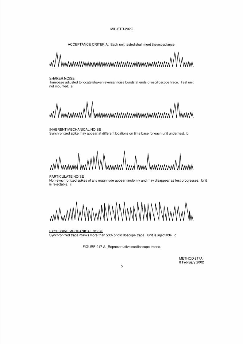
7/29/2019 TEST METHOD STANDARD ELECTRONIC AND ELECTRICAL COMPONENT PARTS
http://slidepdf.com/reader/full/test-method-standard-electronic-and-electrical-component-parts 149/191
MIL-STD-202G
ACCEPTANCE CRITERIA: Each unit tested shall meet the acceptance.
SHAKER NOISETimebase adjusted to locate shaker reversal noise bursts at ends of oscilloscope trace. Test unitnot mounted. a
INHERENT MECHANICAL NOISESynchronized spike may appear at different locations on time base for each unit under test. b
PARTICULATE NOISENon-synchronized spikes of any magnitude appear randomly and may disappear as test progresses. Unitis rejectable. c
EXCESSIVE MECHANICAL NOISESynchronized trace masks more than 50% of oscilloscope trace. Unit is rejectable. d
FIGURE 217-2. Representative oscilloscope traces.
METHOD 217A8 February 2002
5

7/29/2019 TEST METHOD STANDARD ELECTRONIC AND ELECTRICAL COMPONENT PARTS
http://slidepdf.com/reader/full/test-method-standard-electronic-and-electrical-component-parts 150/191
MIL-STD-202G
A. Unit under test.B. Holding fixture.C. Holding spring.D. Angle indicator and adjustment.
E. Holding and dropping pin.F. Dropping arm.
FIGURE 217-3. Shock test fixture.
METHOD 217A8 February 2002
6

7/29/2019 TEST METHOD STANDARD ELECTRONIC AND ELECTRICAL COMPONENT PARTS
http://slidepdf.com/reader/full/test-method-standard-electronic-and-electrical-component-parts 151/191
MIL-STD-202G
CLASS 300
ELECTRICAL-CHARACTERISTICS TESTS

7/29/2019 TEST METHOD STANDARD ELECTRONIC AND ELECTRICAL COMPONENT PARTS
http://slidepdf.com/reader/full/test-method-standard-electronic-and-electrical-component-parts 152/191

7/29/2019 TEST METHOD STANDARD ELECTRONIC AND ELECTRICAL COMPONENT PARTS
http://slidepdf.com/reader/full/test-method-standard-electronic-and-electrical-component-parts 153/191
MIL-STD-202G
METHOD 301
DIELECTRIC WITHSTANDING VOLTAGE
1. PURPOSE. The dielectric withstanding voltage test (also called high-potential, over potential, voltage-breakdown, or dielectric-strength test) consists of the application of a voltage higher than rated voltage for a specifictime between mutually insulated portions of a component part or between insulated portions and ground. This isused to prove that the component part can operate safely at its rated voltage and withstand momentaryoverpotentials due to switching, surges, and other similar phenomena. Although this test is often called a voltagebreakdown or dielectric-strength test, it is not intended that this test cause insulation breakdown or that it be used fordetecting corona, rather, it serves to determine whether insulating materials and spacing in the component part areadequate. When a component part is faulty in these respects, application of the test voltage will result in eitherdisruptive discharge or deterioration. Disruptive discharge is evidenced by flashover (surface discharge), sparkover(air discharge), or breakdown (puncture discharge). Deterioration due to excessive leakage currents may changeelectrical parameters or physical characteristics.
1.1 Precautions. The dielectric withstanding voltage test should be used with caution particularly in inplant qualityconformance testing, as even an overpotential less than the breakdown voltage may injure the insulation and therebyreduce its safety factor. Therefore, repeated application of the test voltage on the same specimen is not
recommended. In cases when subsequent application of the test potential is specified in the test routine, it isrecommended that the succeeding tests be made at reduced potential. When either alternating-current (ac) or direct-current (dc) test voltages are used, care should be taken to be certain that the test voltage is free of recurringtransients or high peaks. Direct potentials are considered less damaging than alternating potentials which areequivalent in ability to detect flaws in design and construction. However, the latter are usually specified because highalternating potentials are more readily obtainable. Suitable precautions must be taken to protect test personnel andapparatus because of the high potentials used.
1.2 Factors affecting use. Dielectric behavior of gases, oils, and solids is affected in various degrees by manyfactors, such as atmospheric temperature, moisture, and pressure; condition and form of electrodes; frequency,waveform, rate of application, and duration of test voltage; geometry of the specimen; position of the specimen(particularly oil-filled components); mechanical stresses; and previous test history. Unless these factors are properlyselected as required by the type of dielectric, or suitable correction factors can be applied, comparison of the resultsof individual dielectric withstanding voltage tests may be extremely difficult.
2. APPARATUS
2.1 High voltage source. The nature of the potential (ac or dc) shall be as specified. When an alternating potentialis specified, the test voltage provided by the high voltage source shall be nominally 60 hertz in frequency and shallapproximate, as closely as possible, a true sine wave in form. Other commercial power frequencies may be used forinplant quality conformance testing, when specified. All alternating potentials shall be expressed as root-mean-square values, unless otherwise specified. The kilovolt-ampere rating and impedance of the source shall be such asto permit operation at all testing loads without serious distortion of the waveform and without serious change involtage for any setting. When the test specimen demands substantial test source power capacity, the regulation ofthe source shall be specified. When a minimum kilovoltampere rating is required, it shall be specified. When a directpotential is specified, the ripple content shall not exceed 5 percent rms of the test potential. When required, asuitable current-limiting device shall be used to limit current surges to the value specified.
2.2 Voltage measuring device. A voltmeter shall be used to measure the applied voltage to an accuracy of at least5 percent, unless otherwise specified. When a transformer is used as a high voltage source of alternating potential, avoltmeter connected across the primary side or across a tertiary winding may be used provided it is previouslydetermined that the actual voltage across the test specimen will be within the allowable tolerance under any normalload condition.
2.3 Leakage current measuring device. When any leakage current requirement is specified, a suitable methodshall be used to measure the leakage current to an accuracy of at least 5 percent of the specified requirement.
METHOD 3016 February 1956
1 of 3
7/29/2019 TEST METHOD STANDARD ELECTRONIC AND ELECTRICAL COMPONENT PARTS
http://slidepdf.com/reader/full/test-method-standard-electronic-and-electrical-component-parts 154/191
MIL-STD-202G
2.4 Fault indicator. Suitable means shall be provided to indicate the occurrence of disruptive discharge andleakage current in case it is not visually evident in the specimen. The voltage measuring device of 2.2, the leakagecurrent measuring device of 2.3, or an appropriate indicator light or an overload protective device may be used for
this purpose.
3. PROCEDURE
3.1 Preparation. When special preparations or conditions such as special test fixtures, reconnections, grounding,isolation, or immersion in water are required, they shall be specified.
3.2 Test voltage. Specimens shall be subjected to a test voltage of the magnitude and nature (ac or dc) specified.
3.3 Points of application. The test voltage shall be applied between mutually insulated portions of the specimen orbetween insulated portions and ground as specified. The method of connection of the test voltage to the specimenshould be specified only when it is a significant factor.
3.4 Rate of application. The test voltage shall be raised from zero to the specified value as uniformly as possible,at a rate of approximately 500 volts (rms or dc) per second, unless otherwise specified. At the option of the
manufacturer, the test voltage may be applied instantaneously during inplant quality conformance testing.
3.5 Duration of application. Unless otherwise specified, the test voltage shall be maintained at the specified valuefor a period of 60 seconds for qualification testing. For inplant quality conformance testing, when specified, reducedtime with a possible correlated higher test voltage may be used. Specimens with movable parts shall be tested asspecified, in a manner to assure that repeated stresses are not applied to the same dielectric. Upon completion ofthe test, the test voltage shall be gradually reduced to avoid surges. At the option of the manufacturer, the testvoltage may be removed instantaneously during inplant quality conformance testing.
3.6 Examination and measurement of specimen. During the dielectric withstanding voltage test, the fault indicatorshall be monitored for evidence of disruptive discharge and leakage current. Following this, the specimen shall beexamined and measurements shall be performed to determine the effect of the dielectric withstanding voltage test onspecific operating characteristics, when specified.
4. SUMMARY. The following details are to be specified in the individual specification:
a. Special preparations or conditions, if required (see 3.1).
b. Magnitude of test voltage (see 3.2).
(1) Test voltage, and duration for inplant quality conformance testing, if different than for qualificationtesting (see 3.5).
c. Nature of potential (ac or dc) (see 2.1).
d. Duration of application of test voltage for qualification testing if other than 60 seconds (see 3.5).
e. Points of application of test voltage (see 3.3).
(1) Method of testing specimens with movable parts (see 3.5).
f. Method of connection of test voltage to specimen, if significant (see 3.3).
g. Regulation, when applicable (see 2.1).
METHOD 3016 February 1956
2

7/29/2019 TEST METHOD STANDARD ELECTRONIC AND ELECTRICAL COMPONENT PARTS
http://slidepdf.com/reader/full/test-method-standard-electronic-and-electrical-component-parts 155/191
MIL-STD-202G
h. Minimum kilovolt-ampere rating of high voltage source, if required. (see 2.1).
i. Limiting value of surge current, if applicable (see 2.1).
j. Maximum leakage current requirement, if applicable (see 2.3).
k. Measurements after dielectric withstanding voltage test, if required (see 3.6).
METHOD 3016 February 1956
3

7/29/2019 TEST METHOD STANDARD ELECTRONIC AND ELECTRICAL COMPONENT PARTS
http://slidepdf.com/reader/full/test-method-standard-electronic-and-electrical-component-parts 156/191
7/29/2019 TEST METHOD STANDARD ELECTRONIC AND ELECTRICAL COMPONENT PARTS
http://slidepdf.com/reader/full/test-method-standard-electronic-and-electrical-component-parts 157/191
MIL-STD-202G
METHOD 302
INSULATION RESISTANCE
1. PURPOSE. This test is to measure the resistance offered by the insulating members of a component part to animpressed direct voltage tending to produce a leakage of current through or on the surface of these members. Aknowledge of insulation resistance is important, even when the values are comparatively high, as these values maybe limiting factors in the design of high-impedance circuits. Low insulation resistances, by permitting the flow of largeleakage currents, can disturb the operation of circuits intended to be isolated, for example, by forming feedbackloops. Excessive leakage currents can eventually lead to deterioration of the insulation by heating or by direct-current electrolysis. Insulation resistance measurements should not be considered the equivalent of dielectricwithstanding voltage or electric breakdown tests. A clean, dry insulation may have a high insulation resistance, andyet possess a mechanical fault that would cause failure in the dielectric withstanding voltage test. Conversely, a dirty,deteriorated insulation with a low insulation resistance might not break down under a high potential. Since insulatingmembers composed of different materials or combinations of materials may have inherently different insulationresistances, the numerical value of measured insulation resistance cannot properly be taken as a direct measure ofthe degree of cleanliness or absence of deterioration. The test is especially helpful in determining the extent to whichinsulating properties are affected by deteriorative influences, such as heat, moisture, dirt, oxidation, or loss of volatilematerials.
1.1 Factors affecting use. Factors affecting insulation resistance measurements include temperature, humidity,residual charges, charging currents of time constant of instrument and measured circuit, test voltage, previousconditioning, and duration of uninterrupted test voltage application (electrification time). In connection with this last-named factor, it is characteristic of certain components (for example, capacitors and cables) for the current to usuallyfall from an instantaneous high value to a steady lower value at a rate of decay which depends on such factors astest voltage, temperature, insulating materials, capacitance, and external circuit resistance. Consequently, themeasured insulation resistance will increase for an appreciable time as test voltage is applied uninterruptedly.Because of this phenomenon, it may take many minutes to approach maximum insulation resistance readings, butspecifications usually require that readings be made after a specified time, such as 1 or 2 minutes. This shortens thetesting time considerably while still permitting significant test results, provided the insulation resistance is reasonablyclose to steady-state value, the current versus time curve is known, or suitable correction factors are applied to thesemeasurements. For certain components, a steady instrument reading may be obtained in a matter of seconds.When insulation resistance measurements are made before and after a test, both measurements should be madeunder the same conditions.
2. APPARATUS. Insulation resistance measurements shall be made on an apparatus suitable for thecharacteristics of the component to be measured such as a megohm bridge, megohm-meter, insulation resistancetest set, or other suitable apparatus. Unless otherwise specified, the direct potential applied to the specimen shall bethat indicated by one of the following test condition letters, as specified:
Test condition Test potential
A 100 volts ±10%B 500 volts ±10%C 1,000 volts ±10%
For inplant quality conformance testing, any voltage may be used provided it is equal to or greater than the minimumpotential allowed by the applicable test condition. Unless otherwise specified, the measurement error at theinsulation resistance value required shall not exceed 10 percent. Proper guarding techniques shall be used toprevent erroneous readings due to leakage along undesired paths.
METHOD 3026 February 1956
1 of 2
7/29/2019 TEST METHOD STANDARD ELECTRONIC AND ELECTRICAL COMPONENT PARTS
http://slidepdf.com/reader/full/test-method-standard-electronic-and-electrical-component-parts 158/191
MIL-STD-202G
3. PROCEDURE. When special preparations or conditions such as special test fixtures, reconnections, grounding,isolation, low atmospheric pressure, humidity, or immersion in water are required, they shall be specified. Insulationresistance measurements shall be made between the mutually insulated points or between insulated points and
ground, as specified. When electrification time is a factor, the insulation resistance measurements shall be madeimmediately after a 2 minute period of uninterrupted test voltage application, unless otherwise specified. However, ifthe instrument reading indicates that an insulation resistance meets the specified limit, and is steady or increasing,the test may be terminated before the end of the specified period. When more than one measurement is specified,subsequent measurements of insulation resistance shall be made using the same polarity as the initialmeasurements.
4. SUMMARY. The following details are to be specified in the individual specification:
a. Test condition letter, or other test potential, if required (see 2).
b. Special preparations or conditions, if required (see 3).
c. Points of measurement (see 3).
d. Electrification time, if other than 2 minutes (see 3).
e. Measurement error at the insulation resistance value required, if other than 10 percent (see 2).
METHOD 3026 February 1956
2

7/29/2019 TEST METHOD STANDARD ELECTRONIC AND ELECTRICAL COMPONENT PARTS
http://slidepdf.com/reader/full/test-method-standard-electronic-and-electrical-component-parts 159/191
MIL-STD-202G
METHOD 303
DC RESISTANCE
1. PURPOSE. This test is to measure the direct-current (dc) resistance of resistors, electromagnetic windings ofcomponents, and conductors. It is not intended that this test apply to the measurement of contact resistance.
1.1. Precautions. The temperature at which the dc resistance measurement is made will affect the final value ofresistance. In addition, resistance values may vary with the measuring voltage.
2. PROCEDURE. DC resistance shall be measured with a resistance bridge or other suitable test equipment. Thelimit of error in the bridge or other test equipment shall not exceed one-tenth of the specified tolerance on the
measured resistance (for example, the limit of error in the bridge or other test equipment shall not exceed ±0.5
percent if the specified tolerance on the measured resistance is ±5 percent), unless otherwise specified. For inplantquality conformance testing, the accuracy of the measurement shall be such to insure that the resistance value iswithin the required tolerance. If a plus or minus tolerance is not specified, the limit of error in the bridge or other test
equipment shall not exceed ±2 percent. The test current through the specimen shall be as small as practicalconsidering the sensitivity of the indicating instruments, unless the test current or voltage is specified. When it isimportant that the temperature of the specimen shall not r ise appreciably during the measurement, the test voltage
shall be applied uninterruptedly for as short a time as practicable, but in no case for more than 5 seconds, unlessotherwise specified. The measurement shall be made at or corrected to 25°C.
3. SUMMARY. The following details are to be specified in the individual specification:
a. Limit of error of measuring apparatus, if other than one-tenth of specified tolerance (see 2).
b. Test voltage or current, if applicable (see 2).
c. Maximum period of uninterrupted test-voltage application, if other than 5 seconds (see 2).
METHOD 3036 February 1956
1 of 1

7/29/2019 TEST METHOD STANDARD ELECTRONIC AND ELECTRICAL COMPONENT PARTS
http://slidepdf.com/reader/full/test-method-standard-electronic-and-electrical-component-parts 160/191
7/29/2019 TEST METHOD STANDARD ELECTRONIC AND ELECTRICAL COMPONENT PARTS
http://slidepdf.com/reader/full/test-method-standard-electronic-and-electrical-component-parts 161/191
MIL-STD-202G
METHOD 304
RESISTANCE-TEMPERATURE CHARACTERISTIC
1. PURPOSE. It is the purpose of this test to determine the percentage change in direct-current (dc) ohmicresistance from the dc ohmic resistance at the reference temperature, per unit temperature difference between thetest temperature and the reference temperature. The equation (see 3) used to calculate this characteristic,commonly called the "temperature coefficient of resistance", is based on an assumed straight-line relationshipbetween resistance and temperature over a range of specified test temperatures.
2. PROCEDURE.
2.1 Preparation. Test leads used to connect the specimens to the resistance-measuring devices shall be firmlyfastened to the specimens. Precautions shall be taken to minimize errors in resistance measurement due to suchfactors as lead resistance, spurious electromotive forces, condensation of moisture, etc., throughout the range of testtemperatures, by utilization of suitable test-lead materials and measurement techniques or by applying appropriatecorrections.
2.2 Test temperatures. The reference temperature shall be 25°C or as specified. There shall be two standard
series of test temperatures. The first series shall be 25°, 0°, -15°, and -55°C; the second series shall be 25°, 50°,75°, 100°, 125°, 200°, 275°, and 350°C. The tolerance on each temperature in both series shall be ±3°C. The lowesttest temperature in the first series, and the highest test temperature in the second series, shall be as specified.Measurements for each series of temperatures shall be performed in the order shown without interruption.However, a lapse of time not to exceed 24 hours is permitted between the end of the first series and the start of thesecond series.
2.3 Measurements. The resistance of each specimen shall be measured 30 to 45 minutes after the chambertemperature has become stable to within ±0.5°C at a test temperature. However, it will be permissible to measurethe resistance before the end of this period if the resistance has become stable to within ±0.1 percent as determinedby preliminary measurements made at 5 minute intervals after stabilization of the chamber temperature. Unlessotherwise specified, the temperature at the time of measurement shall be measured to an accuracy of ±1 percent ofthe temperature difference between the nominal test temperature and the nominal reference temperature +0.5°C.Resistance measurements shall be made in accordance with method 303 of this standard.
3. RESULTS. The resistance-temperature characteristic, in percent change in resistance per degree centigrade,at each test temperature shall be computed as follows:
Where:R1 = resistance at reference temperature (in same series as test temperature) in ohms.R2 = resistance at test temperature in ohms.t1 = reference temperature in degrees celsius.t2 = test temperature in degrees celsius.
4. SUMMARY. The following details are to be specified in the individual specification:
a. Reference temperature, if other than that specified (see 2.2).
b. Lowest and highest test temperature (see 2.2).
c. Accuracy of temperature measurement if other than that specified (see 2.3).
METHOD 30424 October 1956
1 of 1
100 X )t - t ( R
R - R = stic characteri e temperatur - Resistance
12 1
12

7/29/2019 TEST METHOD STANDARD ELECTRONIC AND ELECTRICAL COMPONENT PARTS
http://slidepdf.com/reader/full/test-method-standard-electronic-and-electrical-component-parts 162/191

7/29/2019 TEST METHOD STANDARD ELECTRONIC AND ELECTRICAL COMPONENT PARTS
http://slidepdf.com/reader/full/test-method-standard-electronic-and-electrical-component-parts 163/191
MIL-STD-202G
METHOD 305
CAPACITANCE
1. PURPOSE. The purpose of this test is to measure the capacitance of component parts. Preferred testfrequencies for this measurement are 60 Hz, 120 Hz, 1 kHz, 100 kHz, and 1 MHz.
2. PROCEDURE. The capacitance of the specimen shall be measured at or referred to an ambient temperature of25°C with a capacitance bridge or other suitable method at the frequency specified. The inherent accuracy of themeasurement shall be ±(0.5 percent +0.2 picofarad) unless otherwise specified. Suitable measurement techniqueshall be used to minimize errors due to the connections between the measuring apparatus and the specimen. Thealternating-current (ac) voltage actually impressed across the specimen shall be as low as practicable. When adirect-current (dc) polarizing voltage is required, it shall be as specified and shall exceed the peak ac voltageimpressed across the specimen; however, the sum of the peak ac and the dc voltages shall not exceed the voltagerating of the specimen.
3. SUMMARY. The following details are to be specified in the individual specification:
a. Test frequency (see 2).
b. Limit of accuracy, if other than that specified (see 2).
c. Magnitude of polarizing voltage, if applicable (see 2).
d. Magnitude of AC rms test signal, if applicable (see 2).
METHOD 30524 October 1956
1 of 1

7/29/2019 TEST METHOD STANDARD ELECTRONIC AND ELECTRICAL COMPONENT PARTS
http://slidepdf.com/reader/full/test-method-standard-electronic-and-electrical-component-parts 164/191
7/29/2019 TEST METHOD STANDARD ELECTRONIC AND ELECTRICAL COMPONENT PARTS
http://slidepdf.com/reader/full/test-method-standard-electronic-and-electrical-component-parts 165/191
MIL-STD-202G
METHOD 306
QUALITY FACTOR (Q)
1. PURPOSE. The purpose of this test is to measure the quality factor, commonly called Q, of electronic partssuch as capacitors and inductors. By definition, the factor Q expresses the ratio of reactance to effective resistanceof a circuit element. This numerical ratio is considered a "figure of merit" for a reactive component (or a resonantcircuit utilizing such components) as it is a measure of the ability of the component (or circuit) to store energycompared to the energy it wastes. For this reason, Q is called "storage factor". Q is thus equal to the inverse of thedissipation factor. Relationship also exists between Q and the properties of a tuned circuit, such as the resonant risein voltage phenomena. Each of the relationships involving Q mentioned above can be applied to the direct or indirectmeasurement of Q.
2. PROCEDURE. The quality factor or Q of the specimen shall be measured using a suitable instrument providingan accuracy of measurement within 10 percent of the specified value of Q. Measurements shall be made at thespecified frequency. Suitable measurement techniques shall be used to minimize errors due to the connectionsbetween the measuring apparatus and the specimen.
3. SUMMARY. The following detail is to be specified in the individual specification:
a. Test frequency (see 2).
METHOD 30624 October 1956
1 of 1

7/29/2019 TEST METHOD STANDARD ELECTRONIC AND ELECTRICAL COMPONENT PARTS
http://slidepdf.com/reader/full/test-method-standard-electronic-and-electrical-component-parts 166/191

7/29/2019 TEST METHOD STANDARD ELECTRONIC AND ELECTRICAL COMPONENT PARTS
http://slidepdf.com/reader/full/test-method-standard-electronic-and-electrical-component-parts 167/191
MIL-STD-202G
METHOD 307
CONTACT RESISTANCE
1. PURPOSE. The purpose of the contact resistance test is to determine the resistance offered to a flow of currentduring its passage between the electrical contacting surfaces of connecting components, such as plugs, jacks,connectors, and sockets, or between the electrical contacts of current controlling components, such as switches,relays, and circuit breakers. For practical reasons, lead and terminal resistances may be included in the actualmeasurement, as well as the contact resistance proper. In many applications it is required that the contact resistancebe low and stable, so that the voltage drop across the contacts does not affect the accuracy of the general circuitconditions. If large currents are passed through high resistance contacts, excessive energy losses and dangerousoverheating of the contacts may occur.
1.1 Precautions. Contact resistance values between two contacting surfaces are influenced by such factors as theresistivities of the surface materials; contact pressure; area; shape; condition (including relative cleanliness,smoothness, and hardness) of surfaces; current; open circuit voltage appearing at the contacts during interruption ofcurrent; temperature; and thermal conductivity of leads. These factors should be considered in designing test jigs orclamps, or in performing contact resistance measurements. Contact resistances are usually measured by a 4-terminal procedure, using a Kelvin bridge, or by the voltmeter-ammeter method. The test current used is usually the
maximum rated current for the contacting surfaces involved. In measuring contact resistance, it is important to keepthe specimen free from vibration, and to prevent changes in normal contact pressure which might result fromimproper application of test jigs or clamps.
2. PROCEDURE. The resistance of the contacts may be measured directly using a Kelvin bridge, or indirectlyusing the voltmeter-ammeter method, ammeter-potentiometer method, or other suitable means. The maximumallowable measurement error shall be 5 percent. The point of measurement shall be the point at which the externalleads are normally connected to the terminals. Connections between the specimens and the measuring apparatusshall be made as specified, using suitable connecting jigs or clamps, where required. The magnitude of direct currentto be passed through the contacts during the measurement and, when necessary, the maximum open circuit testvoltage shall be as specified. A series resistor may be used provided the specified open circuit test voltage is notexceeded. The number of activations to cleanse the contacts prior to measurement, the number of test activations,and the number of measurements per activations to be made on each contact shall be as specified.
3. SUMMARY. The following details are to be specified in the individual specification:
a. Method of connection (see 2).
b. Test current (see 2).
c. Maximum open circuit test voltage, if applicable (see 2).
d. Number of activations prior to measurement (see 2).
e. Number of test activations (see 2).
f. Number of measurements per activation (see 2).
METHOD 30724 October 1956
1 of 1

7/29/2019 TEST METHOD STANDARD ELECTRONIC AND ELECTRICAL COMPONENT PARTS
http://slidepdf.com/reader/full/test-method-standard-electronic-and-electrical-component-parts 168/191

7/29/2019 TEST METHOD STANDARD ELECTRONIC AND ELECTRICAL COMPONENT PARTS
http://slidepdf.com/reader/full/test-method-standard-electronic-and-electrical-component-parts 169/191
MIL-STD-202G
METHOD 308
CURRENT-NOISE TEST FOR FIXED RESISTORS
1. PURPOSE. This resistor noise test method is performed for the purpose of establishing the "noisiness" or"noise quality" of a resistor in order to determine its suitability for use in electronic circuits having critical noiserequirements. This method is intended as a standard reference for the determination of current noise present in aresistor, for use in an application with specific current-noise requirements. It is not intended as a generalspecification requirement. Interference caused by the generation of spurious noise signals in parts tends to mask thedesired output signal, thus resulting in loss of information. For low-level audio frequency and other low-frequencycircuits, where low-noise parts are used, resistors may become an important source of interfering noise. One sourceof noise in a resistor is molecular thermal motion which generates a fluctuation voltage termed "thermal noise". It isnot necessary to determine the magnitude of thermal noise by measurement since the mean-square value of thefluctuation voltage is predictable from Nyquist's equation, which shows the mean-square value to be proportional tothe product of resistance, temperature, and the pass band of the measuring system. Generally, an increase influctuation voltage appears when direct current (dc) is passed through resistive circuit elements. The increase influctuation voltage is termed "excess noise" or "current noise". The magnitude of current noise is dependent uponmany inherent properties of the resistor such as resistive material and other factors such as processing, fabrication,size and shape of resistive element, etc. Since there is no apparent functional relationship between current noise
and many of these factors, current noise generally cannot be predicted from physical constants. Therefore, it isnecessary to measure current noise to determine its magnitude. The method employed in this test has beendesigned to evaluate accurately the "noisiness" or "noise quality" of individual resistors in terms of a noise-qualityindex. The noise-quality index, expressed in decibels (dB), is a measure of the ratio of the root-mean-square (rms)
value of current-noise voltage, in microvolts (µv), to the applied dc voltage, in volts. The pass band associated withthe noise-quality index is one frequency decade, geometrically centered at 1,000 hertz (Hz). This index is termed the"microvolts-per-volt-in-a-decade" index. In the design of circuits, an added advantage accrues from the definitivenessof the index which allows the estimation of interference attributable to current noise. Conversely, for a given limit ofcurrent-noise interference in a particular circuit design, a maximum acceptable value of the index may be established.Ordinarily, it is not necessary to duplicate the operating conditions of the particular circuit design when measuring thecurrent noise. The noise quality of populations of resistors may be reasonably estimated by measurement of theindex of representative groups of resistors using suitable sampling procedures. Measurements on sample groupstend to have a normal distribution and once representative parameter values for the distribution have beenestablished (the mean and standard deviation), such parameter values would serve as norms in judging "noisiness"and product uniformity insofar as noise is concerned.
1.1 Precautions. Adherence to the ambient temperature specified in 3.1 is emphasized as an importantconsideration of this method. It is also necessary, in making noise measurements, using the apparatus of thismethod, to delay reading the noise meter for a period of time no less than four times the effective time constant of thedetector to allow the meter sufficient time to reach at least 98 percent of the representative average value. Theeffective time constant of the apparatus is normally adjusted to a value close to 1 second and therefore, a minimumtime delay of 4 seconds is normally required for the noise meter to indicate a valid average. Immediately after this 4second delay, the meter should be read even though it continues to fluctuate as the noise signal varies. Normally,the operator in making a visual reading of the fluctuating meter pointer, should estimate an average for a shortduration, in the order of 1/2 to 1 second.
METHOD 30829 November 1961
1 of 8

7/29/2019 TEST METHOD STANDARD ELECTRONIC AND ELECTRICAL COMPONENT PARTS
http://slidepdf.com/reader/full/test-method-standard-electronic-and-electrical-component-parts 170/191
MIL-STD-202G
2. APPARATUS. Noise measurements should be made on Quan-Tech Laboratories, Inc., Model 315 Resistor-Noise Test Set, or equal, built in conformance with specifications recommended by the National Bureau of Standards(NBS) and detailed in a report entitled "A Recommended Standard Resistor-Noise Test System," by G.T. Conrad, Jr.,
N. Newman, and A.P. Stansbury published in the IRE Transactions of the Professional Group on Component Parts,Volume CP-7, Number 3, September 1960. The NBS-test system provides a means for establishing direct currentthrough the resistor under test and measuring the resulting dc voltage and noise voltage appearing at the terminals ofthe resistor. These two voltages are indicated simultaneously on scales calibrated in db. Instrumentation is soarranged that the associated value of the "microvolts-per-volt-in-a-decade" index may be readily determined inaccordance with 3.3.
2.1 Test system. The test system shall be as shown in the simplified block diagram on figure 308-1. The dcportion of the system consists of a variable dc power supply and a dc vacuum-tube voltmeter (VTVM). Thealternating-current (ac) portion of the system consists of a calibration signal source and an indicating amplifier. Theinterconnecting leads, as well as the resistor under test, should be adequately shielded.
2.1.1 DC measurement considerations. The variable dc power supply furnishes dc loading power through anisolation resistor to the resistor under test. The isolation resistor prevents noise, appearing at the terminals of theresistor under test, from being severely attenuated by the very low, parallel impedance presented by the output
terminals of the dc power supply. The isolation resistor must be free of current noise. Quiet wirewound-type resistorsare suitable. One of four values for the isolation resistor, Rm, (1,000 ohms, 10,000 ohms, 100,000 ohms, or 1megohm (mego)) is selected, depending on the resistance of the resistor under test, RT. The dc voltage appearingacross the resistor under test is indicated by the dc VTVM. The meter has two scales - one showing the dc voltageacross the resistor under test, V, and the other indicating the quantity D-20 log V, in dB. The scale simplifiescomputation of the current-noise index. The choice of value of the dc voltage is not critical, however, to avoidsubjecting the resistor under test, and the isolation resistor as well, to excessive dc power dissipation or voltage, orboth, standard nominal values of dc voltage and values for the isolation resistor are given in table 308-1.
2.1.2 AC measurement considerations. Noise voltage appearing at the terminals of the resistor under test isamplified and its rms magnitude is shown by the ac indicating amplifier. The indicating amplifier consists of a high-gain, low-noise amplifier, a filter, an rms detector, and an output meter. The filter restricts the frequency response ofthe amplifier to a flat-top, 1,000 Hz pass band, geometrically centered at 1,000 Hz. The output-meter scale, like thatof the dc VTVM, is calibrated in dB to simplify calculations.
FIGURE 308-1. Block diagram of system.
METHOD 30829 November 1961
2

7/29/2019 TEST METHOD STANDARD ELECTRONIC AND ELECTRICAL COMPONENT PARTS
http://slidepdf.com/reader/full/test-method-standard-electronic-and-electrical-component-parts 171/191
MIL-STD-202G
2.1.3 Calibration technique. The calibration technique consists of first applying a predetermined value of 1,000 Hz,sine-wave signal across a 1 ohm resistor located in series with the resistor under test, and then adjusting the gain ofthe amplifier, by means of a variable attenuator, until the output meter deflects to the "calibrate" line. This procedure
standardizes the gain of the system and calibrates the indicating amplifier. It should be noted that since thecalibration setting depends upon the impedance at 1,000 Hz of the resistor under test, resistors having the same dcresistance may not calibrate alike. The resistance of the calibration resistor (1 ohm) is considered negligiblecompared to that of any resistor under test (100 ohms to 22 mego); therefore, the effect of the calibration voltageappearing at the terminals of a zero-impedance generator located in series with the resistor under test. Themagnitude of the calibration voltage is so chosen that the indicated output is equal to that which would be obtained if
the calibration voltage were a noise voltage having an rms value of 1,000 µv in a decade. Such a signal should
produce a reading of 60 dB when the system is properly calibrated; thus, 0 dB means 1 µv in a decade.
2.2 Synopsis. To summarize, this apparatus provides a measure of the rms value of the current-noise voltagegenerated in the resistor under test and transmitted in a frequency decade. The calibration technique refers themeasured noise voltage to the terminals of an essentially zero-impedance noise-voltage generator located in serieswith the resistor under test. The noise voltage so measured, when corrected for the presence of system noise, is the"open circuit" current-noise voltage of the resistor under test. Since both the current-noise voltage and dc voltage areexpressed in dB, the value of the “microvolts-per-volt-in-a-decade" index is obtained by subtracting the dc reading
from the corrected noise reading. The corrected noise reading is discussed in 3.3.
3. PROCEDURE.
3.1 Operating conditions. The test shall be performed at an ambient temperature of 25°C ±2°C, unless otherwisespecified. The specimen under test shall be stabilized at room ambient temperature prior to test. No specialpreparations of the specimen are required other than that its leads be clean. Standard operating conditions, basedon the resistance value of the specimen to be tested, are given in table 308-1. The values of the isolation resistor,Rm, and the dc voltage, V, should be observed, although they are not critical, because the index is reasonablyindependent of the values of the isolation resistor and the dc voltage over a broad range. Therefore, it is notnecessary to obtain the exact value of dc voltage given in table 308-1, rather to set it near the value, and to readcarefully and record its value at the time of the measurement. In no case shall the ratings of the resistor under testbe exceeded.
3.2 Measurements. After the operating conditions have been established, the measurement operation shall beperformed in three steps, as follows:
(1) Calibration (see 3.2.1).
(2) Measurement of system noise (see 3.2.2).
(3) Simultaneous measurement of the dc voltage and the resulting total noise (see 3.2.3).
Generally, the measurements should be made in the order listed. The precautions in 1.1 should be observed.
3.2.1 Calibration. The calibration technique (see 2.1.3) standardizes the gain of the ac system for the particularresistor under test. For the noise measurements in steps 2 and 3 which follow, the sum of the ac attenuator settingand the ac meter reading, in dB, is a direct indication of the noise present in terms of an "open-circuit" rms noisevoltage appearing across the terminals of the resistor under test.
METHOD 30829 November 1961
3

7/29/2019 TEST METHOD STANDARD ELECTRONIC AND ELECTRICAL COMPONENT PARTS
http://slidepdf.com/reader/full/test-method-standard-electronic-and-electrical-component-parts 172/191
MIL-STD-202G
TABLE 308-1. Standard operating conditions.
| | | |
| Resistance | Resistors 1/2 watt and higher | Resistors 1/4, 1/8, and 1/10 watt || | | | | | | | || Resistor | Isolation | 20 log V(D) | DC voltage | DC power | 20 log V(D) | DC voltage | DC power || under | resistor | | (V) 1/ | dissipation | | (V) 1/ | dissipation || test (Rt) | (Rm) | | | (Pdc) | | | (Pdc) || | | | | | | | || Ohms | Ohms | dB | Volts | Milliwatts | dB | Volts | Milliwatts || | | | | | | | || 100 | 1,000 | 10.1 | 3.2 | 100 | 10.1 | 3.2 | 100 || 120 | 1,000 | 11.6 | 3.8 | 120 | 10.9 | 3.5 | 100 || 150 | 1,000 | 13.5 | 4.7 | 150 | 11.8 | 3.9 | 100 || 180 | 1,000 | 15.1 | 5.7 | 180 | 12.5 | 4.2 | 100 || 220 | 1,000 | 16.9 | 7.0 | 220 | 13.4 | 4.7 | 100 || 270 | 1,000 | 18.3 | 8.2 | 250 | 14.3 | 5.2 | 100 || 330 | 1,000 | 19.2 | 9.7 | 250 | 15.1 | 5.7 | 100 |
| 390 | 1,000 | 19.9 | 9.9 | 250 | 15.8 | 6.2 | 100 || 470 | 1,000 | 20.7 | 10.8 | 250 | 16.7 | 6.9 | 100 || 560 | 1,000 | 21.4 | 11.8 | 250 | 17.5 | 7.5 | 100 || 680 | 1,000 | 22.3 | 13.0 | 250 | 18.3 | 8.2 | 100 || 820 | 1,000 | 23.1 | 14.3 | 250 | 19.2 | 9.1 | 100 || | | | | | | | || 1,000 | 1,000 | 24.0 | 15.8 | 250 | 20.0 | 10.0 | 100 || 1,200 | 1,000 | 24.8 | 17.3 | 250 | 20.8 | 11.0 | 100 || 1,500 | 1,000 | 25.8 | 19.4 | 250 | 21.7 | 12.2 | 100 || 1,800 | 1,000 | 26.6 | 21.2 | 250 | 22.5 | 13.4 | 100 || 2,200 | 1,000 | 27.4 | 23.4 | 250 | 23.4 | 14.8 | 100 || 2,700 | 10,000 | 28.3 | 26.0 | 250 | 24.3 | 16.4 | 100 || 3,300 | 10,000 | 29.2 | 28.7 | 250 | 25.2 | 18.2 | 100 || 3,900 | 10,000 | 29.9 | 31.2 | 250 | 25.9 | 19.7 | 100 || 4,700 | 10,000 | 30.8 | 34.3 | 250 | 26.7 | 21.7 | 100 |
| 5,600 | 10,000 | 31.5 | 37.4 | 250 | 27.5 | 23.7 | 100 || 6,800 | 10,000 | 32.3 | 41.2 | 250 | 28.3 | 26.1 | 100 || 8,200 | 10,000 | 33.2 | 45.3 | 250 | 29.1 | 28.6 | 100 || | | | | | | | || 10,000 | 10,000 | 34.0 | 50.0 | 250 | 30.1 | 32.0 | 100 || 12,000 | 10,000 | 34.8 | 54.8 | 250 | 30.9 | 35.0 | 100 || 15,000 | 10,000 | 35.8 | 61.2 | 250 | 31.8 | 39.0 | 100 || 18,000 | 10,000 | 36.6 | 67.1 | 250 | 32.5 | 42.0 | 100 || 22,000 | 10,000 | 37.4 | 74.2 | 250 | 33.4 | 47.0 | 100 || 27,000 | 0.10 mego | 38.3 | 82.2 | 250 | 34.3 | 52.0 | 100 || 33,000 | 0.10 mego | 39.2 | 90.8 | 250 | 35.1 | 57.0 | 100 || 39,000 | 0.10 mego | 40.0 | 98.7 | 250 | 35.8 | 62.0 | 100 || 47,000 | 0.10 mego | 40.7 | 108 | 250 | 36.7 | 69.0 | 100 || 56,000 | 0.10 mego | 41.5 | 118 | 250 | 37.5 | 75.0 | 100 || 68,000 | 0.10 mego | 42.3 | 130 | 250 | 38.3 | 82.0 | 100 || 82,000 | 0.10 mego | 43.1 | 143 | 250 | 39.2 | 91.0 | 100 |
See footnote at end of table.
METHOD 30829 November 1961
4

7/29/2019 TEST METHOD STANDARD ELECTRONIC AND ELECTRICAL COMPONENT PARTS
http://slidepdf.com/reader/full/test-method-standard-electronic-and-electrical-component-parts 173/191
MIL-STD-202G
TABLE 308-1. Standard operating conditions - Continued.
| | | |
| Resistance | Resistors 1/2 watt and higher | Resistors 1/4, 1/8, and 1/10 watt || | | | | | | | || Resistor | Isolation | 20 log V(D) | DC voltage | DC power | 20 log V(D) | DC voltage | DC power || under | resistor | | (V) 1/ | dissipation | | (V) 1/ | dissipation || test (Rt) | (Rm) | | | (Pdc) | | | (Pdc) || | | | | | | | || Ohms | Ohms | dB | Volts | Milliwatts | dB | Volts | Milliwatts || | | | | | | | || 0.10 mego | 0.10 mego | 44.0 | 158 | 250 | 40.0 | 100 | 100 || 0.12 mego | 0.10 mego | 44.8 | 173 | 250 | 40.8 | 110 | 100 || 0.15 mego | 0.10 mego | 45.8 | 194 | 250 | 41.7 | 122 | 100 || 0.18 mego | 0.10 mego | 46.5 | 212 | 250 | 42.5 | 134 | 100 || 0.22 mego | 0.10 mego | 47.5 | 234 | 250 | 43.4 | 148 | 100 || 0.27 mego | 1.0 mego | 38.6 | 85.0 | 26.8 | 38.6 | 85.0 | 26.8 || 0.33 mego | 1.0 mego | 40.0 | 99.0 | 29.7 | 40.0 | 99.0 | 29.7 |
| 0.39 mego | 1.0 mego | 41.0 | 112 | 32.2 | 41.0 | 112 | 32.2 || 0.47 mego | 1.0 mego | 42.1 | 127 | 34.3 | 42.1 | 127 | 34.3 || 0.56 mego | 1.0 mego | 43.1 | 143 | 36.5 | 43.1 | 143 | 36.5 || 0.68 mego | 1.0 mego | 44.2 | 161 | 38.1 | 44.2 | 161 | 38.1 || 0.82 mego | 1.0 mego | 45.1 | 180 | 39.5 | 45.1 | 180 | 39.5 || | | | | | | | || 1.0 mego | 1.0 mego | 46.0 | 200 | 40.0 | 46.0 | 200 | 40.0 || 1.2 mego | 1.0 mego | 46.8 | 218 | 39.6 | 46.8 | 218 | 39.6 || 1.5 mego | 1.0 mego | 47.6 | 240 | 38.4 | 47.6 | 240 | 38.4 || 1.8 mego | 1.0 mego | 48.0 | 250 | 34.7 | 48.0 | 250 | 34.7 || 2.2 mego | 1.0 mego | 48.0 | 250 | 28.4 | 48.0 | 250 | 28.4 || 2.7 mego | 1.0 mego | 48.0 | 250 | 23.2 | 48.0 | 250 | 23.2 || 3.3 mego | 1.0 mego | 48.0 | 250 | 18.9 | 48.0 | 250 | 18.9 || 3.9 mego | 1.0 mego | 48.0 | 250 | 16.0 | 48.0 | 250 | 16.0 || 4.7 mego | 1.0 mego | 48.0 | 250 | 13.3 | 48.0 | 250 | 13.3 |
| 5.6 mego | 1.0 mego | 48.0 | 250 | 11.2 | 48.0 | 250 | 11.2 || 6.8 mego | 1.0 mego | 48.0 | 250 | 9.2 | 48.0 | 250 | 9.2 || 8.2 mego | 1.0 mego | 48.0 | 250 | 7.6 | 48.0 | 250 | 7.6 || | | | | | | | || 10 mego | 1.0 mego | 48.0 | 250 | 6.2 | 48.0 | 250 | 6.2 || 12 mego | 1.0 mego | 48.0 | 250 | 5.2 | 48.0 | 250 | 5.2 || 15 mego | 1.0 mego | 48.0 | 250 | 4.2 | 48.0 | 250 | 4.2 || 18 mego | 1.0 mego | 48.0 | 250 | 3.5 | 48.0 | 250 | 3.5 || 22 mego | 1.0 mego | 48.0 | 250 | 2.8 | 48.0 | 250 | 2.8 |
1/ DC voltage across the resistors under test for the measurement of total noise.
METHOD 30829 November 1961
5

7/29/2019 TEST METHOD STANDARD ELECTRONIC AND ELECTRICAL COMPONENT PARTS
http://slidepdf.com/reader/full/test-method-standard-electronic-and-electrical-component-parts 174/191
MIL-STD-202G
3.2.2 System noise (S). System noise is the background noise present when direct current is not present in theresistor under test. System noise is indicated after turning off the calibration voltage. The algebraic sum of the acattenuator setting and the ac meter reading gives the magnitude of system noise, S, in dB.
3.2.3 Total noise (T). Both the dc voltage and the total noise are measured simultaneously. The value of dcvoltage is given in table 308-1. The application of excessive dc voltage should be avoided by setting the dc voltagecontrol to its minimum before applying the voltage, and when the voltage is applied, it should be increased to thedesired value. The magnitude of the dc voltage is given by the sum, D, of the dc attenuator setting and the dc meterreading in dB. D equals 20 log V, where V is the dc voltage, in volts, applied to the terminals of the resistor undertest. The associated noise measurement indicates the total noise present, i.e., the quadratic sum of the system noiseand the current noise. This total noise is indicated by T, in dB.
3.3 Determination of the "microvolts-per-volt-in-a-decade" index. The current-noise index to be compared with therequired index (see 5) shall be computed from the three measured quantities S, T, and D, in accordance with thefollowing formula:
(Index), in dB = T-f(T-S)-D.
Where:
10 - 1 10 - = S)- f(T 10
S - T - log
The quantity f(T-S) is a correction for the presence of system noise while T is being measured. Values of f(T-S) aregiven in table 308-2 as a function of T-S. The quantity T-S represents the indicated increase in noise resulting fromthe presence of direct current. When this increase, T-S, is greater than 15.0 dB, then f(T-S) is essentially zero, and Talone is the measure of current noise.
4. ERRORS. Accuracy and repeatability of determinations of the current-noise index are influenced by thecombined effects of many factors including the following - characteristics of the test set, ambient temperature,inherent fluctuations in current noise, relative magnitude of current noise as compared to system noise, and delaybetween the application of dc voltage and observation of meter deflection. Therefore, in the interest of a better
understanding of the significance of the measurement, a discussion of errors is included. The error associated withthe determination of the index is a function of two independent errors, one a bias-type or constant error, and the othera random-type or variable error. The bias error is constant for any particular measuring condition. The maximumbias error introduced by the test set should not exceed 0.4 dB. A conservative estimate of the bias error introducedby the permissible departure of ambient temperature from 25°C as stated in 3.1, is at most 0.2 dB. The "worst case"bias error for these two factors is the sum of their absolute values, 0.6 dB. Although the bias error for any particularmeasurement is not known, for purposes of this discussion the "worst case" condition is assumed, and 0.6 dB will beconsidered the magnitude of bias error associated with the index. The random error associated with the index is thatof the current noise, [T-f(T-S)]. The index will be considered for two cases; the more simple case where the current
noise is relatively large, i.e., T-S>15.0 dB for which f(T-S)≈0, and therefore current noise is represented by T alone;and the second case where the current noise is not relatively large and is represented by [T-f(T-S)], with f(T-S) beingsignificant. In either case, the probable error of the index is approximately equal to the error component whichpredominates, whether it be bias error or random error. For the first case, the only significant quantity which varies isT, therefore the random-error component of the index error is equal to the random error associated with themeasurement of the total noise, T. The random error of T is evidenced by fluctuations of the meter pointer and tendsto have a normal distribution. The magnitude of the probable random error of T cannot be given explicitly because itsvalue is necessarily a function of the resistor under test and must be determined from measurements. The probablerandom error of T for different resistors may range from values as low as approximately 0.2 dB to values as high asseveral dB in resistors having large noise variations.
METHOD 30829 November 1961
6
7/29/2019 TEST METHOD STANDARD ELECTRONIC AND ELECTRICAL COMPONENT PARTS
http://slidepdf.com/reader/full/test-method-standard-electronic-and-electrical-component-parts 175/191
MIL-STD-202G
For resistors having a probable random error of T less than 0.6 dB, the probable error of the index is approximatelyequal to the bias error, assuming the bias error is the "worst case", i.e., 0.6 dB. This means that on the average, one-half of the measurements would have an error no greater than 0.6 dB. On the other hand, when the probable random
error of T is greater than the bias error, the probable error of the index is equal to that of T. For the second case, theprobable random-error component of the index is greater than that of T alone. This follows because the magnitude ofcurrent noise is determined from the difference between two measurements, T and S, each of which fluctuates, ratherthan from T alone. Measurements indicate that the probable random error of S should be in the order of 0.2 dB.Assuming that this is the case, the probable random-error component of the index is approximately double that of Tfor the measurement condition T-S = 3 dB, and approximately four times that of T for the condition T-S = 1.5 dB. Thelimit of sensitivity for measuring the current-noise index is approached as the current noise approaches values toosmall to cause an increase as much as 1.0 dB, i.e., T-S equal to 1.0 dB. However, the test method may serve as aqualitative means for comparing resistors having relatively low values of current noise where T-S is less than 1.0 dB.Another possible source of measurement uncertainty is the transitory variations in current noise which mayimmediately follow application of dc voltage. Certain types of resistors tend to display very little, if any, transitoryvariations, whereas other types tend to display such variations to a measurable degree. For those resistors whichexhibit such variations, the current noise usually settles to a more stable value after a short time, from 1 to severalseconds. In some cases, the current-noise variations may continue to be relatively large and unstable for extendedperiods of time. Such resistors are usually very noisy. By adhering to the precautions regarding the procedures
stated in 1.1, the effects of such variations on repeated measurements are reduced.
5. SUMMARY. The following requirement and details are to be provided when this method is specified:
a. Required values of the "microvolts-per-volt-in-a-decade" index (see 3.3).
b. Ambient temperature, if other than that specified (see 3.1).
c. Value of dc voltage, if other than those stated in table 308-1 (see 2.1.1 and 3.1).
METHOD 30829 November 1961
7
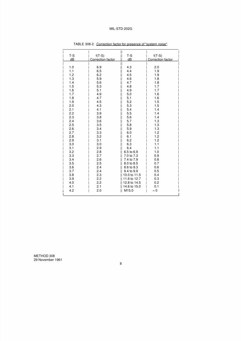
7/29/2019 TEST METHOD STANDARD ELECTRONIC AND ELECTRICAL COMPONENT PARTS
http://slidepdf.com/reader/full/test-method-standard-electronic-and-electrical-component-parts 176/191
MIL-STD-202G
TABLE 308-2. Correction factor for presence of "system noise".
| | || | |
| T-S | f(T-S) || T-S | f(T-S) || dB | Correction factor || dB | Correction factor || | || | || 1.0 | 6.9 || 4.3 | 2.0 || 1.1 | 6.5 || 4.4 | 1.9 || 1.2 | 6.2 || 4.5 | 1.9 || 1.3 | 5.9 || 4.6 | 1.8 || 1.4 | 5.6 || 4.7 | 1.8 || 1.5 | 5.3 || 4.8 | 1.7 || 1.6 | 5.1 || 4.9 | 1.7 || 1.7 | 4.9 || 5.0 | 1.6 || 1.8 | 4.7 || 5.1 | 1.6 || 1.9 | 4.5 || 5.2 | 1.5 || 2.0 | 4.3 || 5.3 | 1.5 || 2.1 | 4.1 || 5.4 | 1.4 |
| 2.2 | 3.9 || 5.5 | 1.4 || 2.3 | 3.8 || 5.6 | 1.4 || 2.4 | 3.6 || 5.7 | 1.3 || 2.5 | 3.5 || 5.8 | 1.3 || 2.6 | 3.4 || 5.9 | 1.3 || 2.7 | 3.3 || 6.0 | 1.2 || 2.8 | 3.2 || 6.1 | 1.2 || 2.9 | 3.1 || 6.2 | 1.2 || 3.0 | 3.0 || 6.3 | 1.1 || 3.1 | 2.9 || 6.4 | 1.1 || 3.2 | 2.8 || 6.5 to 6.9 | 1.0 || 3.3 | 2.7 || 7.0 to 7.3 | 0.9 || 3.4 | 2.6 || 7.4 to 7.9 | 0.8 || 3.5 | 2.5 || 8.0 to 8.5 | 0.7 || 3.6 | 2.4 || 8.6 to 9.3 | 0.6 |
| 3.7 | 2.4 || 9.4 to 9.9 | 0.5 || 3.8 | 2.3 || 10.0 to 11.5 | 0.4 || 3.9 | 2.2 || 11.6 to 12.7 | 0.3 || 4.0 | 2.2 || 12.8 to 14.5 | 0.2 || 4.1 | 2.1 || 14.6 to 15.0 | 0.1 |
| 4.2 | 2.0 || M15.0 | ≈ 0 II I
METHOD 30829 November 1961
8

7/29/2019 TEST METHOD STANDARD ELECTRONIC AND ELECTRICAL COMPONENT PARTS
http://slidepdf.com/reader/full/test-method-standard-electronic-and-electrical-component-parts 177/191
MIL-STD-202G
METHOD 309
VOLTAGE COEFFICIENT OF RESISTANCE DETERMINATION PROCEDURE
1. PURPOSE. Certain types of resistors exhibit a variation of resistance with changes in voltage across theresistor. This is a measurable characteristic; a test to determine the magnitude of such a characteristic is the VoltageCoefficient of Resistance Determination Procedure.
2. PROCEDURE. The voltage coefficient is applicable only to resistors of 1,000 ohms and over. Unless otherwisespecified in the individual specification, all measurements and tests shall be made at a temperature of 25°C ±5°C.Adjust the resistance measuring device to apply 0.1 X rated continuous working voltage to the resistor. Measure theresistance by applying this voltage intermittently for not more than the total of 0.5 second in any 5 second interval.Readjust the resistance measuring device to apply 1.0 X rated continuous working voltage to the resistor and repeatthe above intermittent measuring procedure. Compute the Voltage Coefficient (VC) as follows:
Er
r R VC
9.0
100)( −=
Where:R = Resistance at rated continuous working voltage.r = Resistance at 0.1 rated continuous working voltage.E = Rated continuous working voltage.
3. PRECAUTIONS. Adherence to 2, applying voltage intermittently for not more than the total of 0.5 seconds inany 5 second interval is emphasized as an important consideration of this method. Failure to comply would result ina voltage coefficient of vast variations. A resistance measuring device capable of withstanding high voltageapplications should be used. Certain types of resistors exhibit a variation of resistance with changes in potentialdifference, this effect being separate and distinct from the change in resistance due to heating effect whether fromapplied voltage or ambient conditions.
4. SUMMARY. The following detail is to be specified in the individual specification:
The continuous working voltage (see 2).
METHOD 30927 May 1965
1 of 1

7/29/2019 TEST METHOD STANDARD ELECTRONIC AND ELECTRICAL COMPONENT PARTS
http://slidepdf.com/reader/full/test-method-standard-electronic-and-electrical-component-parts 178/191
7/29/2019 TEST METHOD STANDARD ELECTRONIC AND ELECTRICAL COMPONENT PARTS
http://slidepdf.com/reader/full/test-method-standard-electronic-and-electrical-component-parts 179/191
MIL-STD-202G
METHOD 310
CONTACT-CHATTER MONITORING
1. PURPOSE. This test is conducted for the purpose of detecting contact-chatter in electrical and electroniccomponent parts having movable electrical contacts, such as relays, switches, circuit breakers, etc., where it isrequired that the contacts do not open or close momentarily, as applicable, for longer than a specified time-duration(see 4.3) under environmental test conditions, such as vibration, shock, or acceleration. This test method providesstandard test procedures for monitoring such "opening of closed contacts" or "closing of open contacts".
2. TEST CIRCUITS.
2.1 Selection. In this method there are two test-circuits: A (see 3.1), and B (see 3.2). The selection of the test-circuit depends largely upon the type of electrical contacts to be tested. Test-circuit B is preferred, wheneverpossible, to avoid contact contamination caused by the formation of carbonaceous deposits on the contacts. Theindividual specification shall specify the test-circuit and time-duration (see 4.3) required in connection with monitoringof shock and vibration tests. The test-circuits listed herein are "recommended" reference circuits. Any comparabletest-circuit which meets the test requirements and the calibration procedures as stated herein, may be used for thistest.
2.1.1 Selection of test-circuit A. Test-circuit A is for monitoring test-specimens with a single set of contacts, for theopening of normally-closed contacts or false closures of normally-opened contacts (see figure 310-1). Test-circuit Ashould not be specified for specimens whose capability includes low-level or dry-circuit ratings (10 milliamperes orless and 2 volts or less for openings or closings less than 10 microseconds); since the current through the electricalcontacts under test from the test-circuit may cause arcing, thus damaging the contacts.
2.1.2 Selection of test-circuit B. Test-circuit B is for monitoring test-specimens with a single set of contacts, for theopening of normally-closed contacts and false closures of normally-open contacts (see figure 310-3). Test-circuit Bshould not be used for openings or closings of less than 10 microseconds. Test-circuit B does not allow current inexcess of 20 milliamperes or an open-circuit voltage in excess of 2-volts during monitoring; which insures that therewill be no arcing, which will cause damage, to low-level and dry-circuit test specimens.
3. TEST SYSTEMS.
3.1 Test-circuit A. The test circuit shall be the thyratron circuit shown on figure 310-1 or an approved equivalentcircuit. The values for R1, C1, and the suppressor grid-cathode voltage, controlled by R7, principally controls thefiring of the thyratron and are so chosen that the thyratron will fire when the duration of the contact-opening exceedsthe time-duration specified in the individual specification (see 4.3 and 5). For the longer time-durations, such asabove 1 millisecond, it may be necessary to change the values of R2, R5, and R6.
a. To monitor normally-closed contacts, the normally-closed contacts are connected to BP1 and BP2, withswitch S1 in the "normally-closed position". The grid of the thyratron is placed at ground potential. Thecathode of the thyratron is at a positive potential (depending on the setting of R7), thus providing sufficientnegative bias to cut the thyratron "off". Any contact chatter (opening of closed contacts) will cause the grid ofthe thyratron to rise exponentially to +150 volts at a rate determined by the preselected time constant of R1and C1. As long as the contacts remain open, the grid potential will continue to rise. If the contacts remain"open" for longer than the specified interval, the grid potential rises to the point at which the thyratronconducts and ionizes, thus lighting DS1. Since, in a thyratron, the grid loses control of conduction as soon asthe tube conducts, the contacts being monitored can reclose at any time thereafter without affecting themonitoring circuit. Thus, lamp DS1 will remain "on" until the thyratron is manually reset by operation ofswitch S2.
METHOD 31020 January 1967
1 of 8

7/29/2019 TEST METHOD STANDARD ELECTRONIC AND ELECTRICAL COMPONENT PARTS
http://slidepdf.com/reader/full/test-method-standard-electronic-and-electrical-component-parts 180/191
MIL-STD-202G
b. To monitor normally-open contacts for false closures, it is necessary to operate switch S1 to the "normally-open position", so that the connection between the +150 volts and the time-constant charging circuit is"open". When open contacts are connected to BP1 and BP2 and the connection is made, these contacts
"close". At contact closure, voltage is applied to the charging circuit, starting a build-up in the same manneras described in (a) for normally-closed contacts. At the conclusion of the test, if lamp DS1 is "off", then therehas been a no-chatter interval exceeding the specified duration; if the lamp is "on", then there was at leastone-interval when the specified time-duration was exceeded. After an indication of failure, the thyratroncircuit shall be restarted by operation of switch S2.
3.1.1 Calibration procedure for test-circuit A. The calibration-circuit shown on figure 310-2 may be used tocalibrate the monitoring-circuit shown on figure 310-1 by using the following procedure:
a. Make the proper connections of the monitoring-circuit to the calibration-circuit as shown, and set switch S1 toposition A.
b. Calibrate the oscilloscope triggering input as follows:
(1) Set switch S4 to position A, so that the trigger input is connected to the Y-axis input of the oscilloscope.
(2) Set the time-base control of the oscilloscope for approximately 20-percent of the time-duration for whichthe calibration is being made.
(3) Set the Y-amplitude of the oscilloscope for 1-volt per centimeter.
(4) Set the triggering coupling to ac sensitivity.
(5) Open the switch S3 and adjust the triggering level and stability control so that the trace on theoscilloscope will trigger at 0.5-volt or less. The closer the trigger-level is to zero, the greater theaccuracy of calibration.
c. Set switch S4 to position B, so that the Y-axis input of the oscilloscope is connected through capacitor C4 tothe plate of the thyratron in the test circuit.
d. Close switch S3.
e. Set the Y-amplitude of the oscilloscope for a usable display, and the time-base as in preceding (b) (2).
f. Depress monitor-circuit reset switch S2 of figure 310-1 to set the circuit in the "ready" position, i.e., with thecircuit being calibrated and lamp DS1 extinguished.
g. Open switch S3; the observed trace of the oscilloscope should move across the screen at a positiveamplitude until it is deflected downward by the negative pulse created when the thyratron fires. The timeinterval between the start of the trace and the negative pulse is the detection time. Adjust R7 of figure 310-1to the time-duration specified in the individual specification.
METHOD 31020 January 1967
2
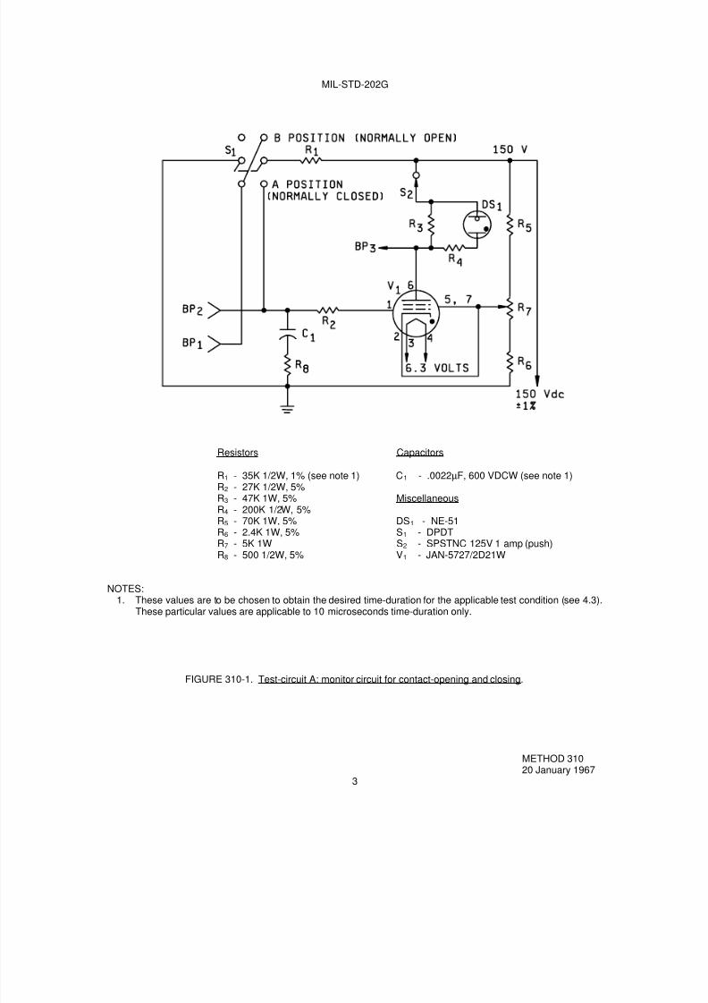
7/29/2019 TEST METHOD STANDARD ELECTRONIC AND ELECTRICAL COMPONENT PARTS
http://slidepdf.com/reader/full/test-method-standard-electronic-and-electrical-component-parts 181/191
MIL-STD-202G
Resistors Capacitors
R1 - 35K 1/2W, 1% (see note 1) C1 - .0022µF, 600 VDCW (see note 1)R2 - 27K 1/2W, 5%
R3 - 47K 1W, 5% MiscellaneousR4 - 200K 1/2W, 5%R5 - 70K 1W, 5% DS1 - NE-51R6 - 2.4K 1W, 5% S1 - DPDTR7 - 5K 1W S2 - SPSTNC 125V 1 amp (push)R8 - 500 1/2W, 5% V1 - JAN-5727/2D21W
NOTES:1. These values are to be chosen to obtain the desired time-duration for the applicable test condition (see 4.3).
These particular values are applicable to 10 microseconds time-duration only.
FIGURE 310-1. Test-circuit A; monitor circuit for contact-opening and closing.
METHOD 31020 January 1967
3

7/29/2019 TEST METHOD STANDARD ELECTRONIC AND ELECTRICAL COMPONENT PARTS
http://slidepdf.com/reader/full/test-method-standard-electronic-and-electrical-component-parts 182/191
METHOD 310
NOTE: The oscilloscope shall have an accuracy of ±3 percent or better on time base and have provision forexternal triggering.
FIGURE 310-2. Calibration circuit for test-circuit A.
3.2 Test circuit B. The monitor-circuit shown on figure 310-3 permits detection of contact-chatter of closed contactsand false closure of open contacts, independently or simultaneously. The low contact-load levels (see 2.1.2) insurethat there will be no arcing of the contacts during monitoring.
a. The chatter portion of figure 310-3, resistors R3 and R4 form a voltage divider with their junction at +2 volts.The closed contacts of the component under test, short-circuit R4 and place the base of transistor amplifierQ1 to ground potential. When the contacts under test "chatter" (open), resistor R4 is no longer short-circuited and capacitor C1 starts to charge through R2 and R7 to +2 volts. The time necessary for C1 tocharge to the correct bias-level is determined by the resistance of R2 and R7 and the capacitance value ofC1. As transistor Q1 draws current through the gate of SCR1, the unit will fire and turn-on lamp DS1. Sincein a silicon-controlled rectifier, the gate loses control after it is turned "on", the contacts can reclose at anytime thereafter without affecting the monitoring circuit. The time-delay, before turn-on, can be adjusted by
varying R2 and selecting the capacitance value of C1. (For example: C1 = .002 µF gives a 10-microsecondopen-contact time.)
b. In the false-make portion of figure 310-3, transistor-amplifier Q2 is normally "on" with the gate of SCR2 beingeffectively held at ground potential by the low-output impedance of transistor Q2. When a "false-make"occurs, the base of Q2 transistor is grounded, turning Q2 "off". This allows the gate of the SCR2, which istied to the collector of transistor Q2, to rise to +12 volts. The rate of increase is determined by the value of
C2 and R8. (For example: C2 = .002 µF gives a 10-microsecond false-make time.) When the voltagereaches the gate turn-on level of SCR2, lamp DS2 will light, indicating a false closure of the open contacts.
METHOD 31020 January 1967
4
7/29/2019 TEST METHOD STANDARD ELECTRONIC AND ELECTRICAL COMPONENT PARTS
http://slidepdf.com/reader/full/test-method-standard-electronic-and-electrical-component-parts 183/191
MIL-STD-202G
c. When this circuit is being used to simultaneously monitor both the open and closed contacts of a double setof contacts:
(1) If DS1 "lights", it is an indication of contact chatter.
(2) If DS1 and DS2 "lights", it is an indication of false transfer or possible bridging, i.e., the movable contactof the open circuit "closes" but the closed circuit has not opened.
(3) If DS2 "lights", it is an indication of bridging.
d. Restoration of the circuit for an indication of failure is accomplished by the operation of S1.
3.2.1 Calibration procedure for test-circuit B. The calibration-circuit shown on figure 310-4 may be used tocalibrate the monitoring-circuit shown on figure 310-3 by using the following procedure:
a. Make the proper connections of the monitoring-circuit to the calibration-circuit.
(1) BP1 and BP2 for contact-chatter calibration.
(2) BP1 and BP3 for false contact-make calibration.
b. Select the appropriate 5 volt square-wave "pulse-polarity" and "pulse-width" to be furnished by the pulsegenerator and monitor the pulse on the oscilloscope, as follows:
(1) For contact-chatter calibration: Negative pulse.
(2) For false contact-make calibration: Positive pulse.
(3) Pulse width for either of the preceding (1) or (2) equal to the required detection time.
c. If DS1 or DS2 (as applicable) "lights", adjust R2 or R8 until the light is extinguished.
d. Slowly adjust R2 and R8 (as applicable) to the time-duration specified in the individual specification, as
indicated by the first point at which DS1 or DS2 "lights".
METHOD 31020 January 1967
5

7/29/2019 TEST METHOD STANDARD ELECTRONIC AND ELECTRICAL COMPONENT PARTS
http://slidepdf.com/reader/full/test-method-standard-electronic-and-electrical-component-parts 184/191
MIL-STD-202G
C1, C2 - Choose for specified time (see note 1) R6 - 1,000 ohms 1/4W, 5%DS1, DS2 - No. 344 Lamp R7 - 100 ohms 1/4W, 5%
R1 - 750 ohms 1/4W, 5% R8 - 200 ohms pot.R2 - 2,000 ohms pot. Q1, Q2 - 2N332A or equivalent
R3, R5 - 10,000 ohms 1/4W, 5% SCR1, SCR2 - 2N1595 or equivalent
R4 - 2,500 ohms 1/4W, 5% S1 - SPST NC Push
NOTE:
1. Use .0022 µF for 10 microsecond time-duration. Other time-duration will require larger capacitors.
FIGURE 310-3. Test-circuit B; monitor circuit for contact-chatter and false closures.
METHOD 31020 January 1967
6

7/29/2019 TEST METHOD STANDARD ELECTRONIC AND ELECTRICAL COMPONENT PARTS
http://slidepdf.com/reader/full/test-method-standard-electronic-and-electrical-component-parts 185/191
MIL-STD-202G
NOTES:1. The square-wave pulse generator and oscilloscope shall have an accuracy of ±3 percent or better.2. The ratio of off-time to detection-time shall be 10:1 or better.
FIGURE 310-4. Calibration circuit for test-circuit B.
METHOD 31020 January 1967
7

7/29/2019 TEST METHOD STANDARD ELECTRONIC AND ELECTRICAL COMPONENT PARTS
http://slidepdf.com/reader/full/test-method-standard-electronic-and-electrical-component-parts 186/191
MIL-STD-202G
4. PROCEDURE.
4.1 Preparation. The monitor-circuits of figures 310-1 and 310-3 shall be calibrated, immediately prior to use, using
the applicable calibration-circuit (see figures 310-2 and 310-4, respectively). The calibration-circuit shall then bedisconnected from the monitoring-circuit.
4.2 Points of connection. The contacts of the test-specimen being monitored shall be connected to points BP1 andBP2 for test circuit A for both contact-chatter and false-make contact conditions. For test circuit B, the points ofconnection shall be BP1 and BP2 for contact-chatter condition and to points BP1 and BP3 for false-make contactcondition. The test specimen shall then be subjected to the shock, vibration, acceleration, or other environmental testduring which this contact-chatter monitoring test method is to be used. If specified in the individual specification, testspecimens having normally-closed contacts may be wired in series to monitor for opening of contacts, and thosehaving normally-open contacts may be wired in parallel to monitor for closing of contacts. In this case, if contactopening or closing is indicated, it will then be necessary to reset each test specimen separately and monitor itindividually to determine which one is defective.
4.3 Test conditions. Test specimens shall be subjected to one of the following test conditions, as specified in theindividual specification:
Test condition Time duration
A 10 microsecondsB 100 microsecondsC 1 millisecondD 5 millisecondsE 20 milliseconds
5. SUMMARY. The following details are to be specified in the individual specification:
a. Test circuit letter (see 2.1, 3.1, and 3.2).
b. Test condition letter for maximum allowable time-duration of contact-opening or closing, as applicable (see4.3).
c. Whether series-connection (of normally-closed contact test-specimens) or parallel-connection (of normally-open contact test-specimens) may be allowed (see 4.2).
METHOD 31020 January 1967
8

7/29/2019 TEST METHOD STANDARD ELECTRONIC AND ELECTRICAL COMPONENT PARTS
http://slidepdf.com/reader/full/test-method-standard-electronic-and-electrical-component-parts 187/191
MIL-STD-202G
METHOD 311
LIFE, LOW LEVEL SWITCHING
1. PURPOSE. This test is conducted for the purpose of determining electrical contact reliability under low-levelswitching conditions in the environment in which the contacts operate. A low level switching circuit is one in whichthe voltage and stored energy are sufficiently small so that the resistance of a pair of contacts is not affected byelectrical phenomena associated with the electrical current flow or the switching. Such a circuit is also one where thevoltage or the current is too low to cause any physical change in the contacts; contact resistance can only be affectedby changes in the contacts caused by mechanical action on the contacts. Electrical loads, which result in arcingacross electrical contacts, affect contact surfaces in many ways, mostly favorable to reduction of contact resistance,since insulating films and small rough raised areas on the contact are burned away or melted down, to reform as amore even and larger contact surface. Under low-level conditions, the advantages, as well as the occasionaldisadvantages of this arcing will be absent. If low-level loads and intermediate or power loads are to be applied todifferent pairs of contacts on the same component part simultaneously, reliability of the low-level conditions can beimpaired due to deposition of foreign materials resulting from vaporization surrounding the contacts operating atlarger loads in the same enclosure or in an adjacent area, because of this fact, and because low-level contacts maydevelop films as a function of their environment, the contacts are tested in an environment similar to that in whichthey are used. This test in no way reflects the contact capability in the intermediate or "minimum" current area and
shall not be considered as a substitute for testing in this area when specified.
2. APPARATUS.
2.1 Test circuit. Monitoring of the contact resistance of each pair of contacts shall be accomplished on each cycle.A separate monitoring indicator shall be used for each pair of contacts. The apparatus, which cyclically operates thecontacts, shall be capable of automatically cycling the contacts at the rate specified. The power source for the open-circuit voltage shall not exceed 30 millivolts dc maximum or peak ac at 10 milliamperes (mA) maximum. Open-circuitvoltage is defined as the voltage that would appear at the contacts, when the circuit is energized and when thecontacts are open. One means of generating this voltage is to pass a stable adjustable current through a low-ohmage resistor (such as a shunt resistor for an ammeter). This means will provide the low impedance, low voltage,controllable, and well defined voltage source necessary. The current shall be adjusted so that the current through thepair of contacts, when closed is limited to 10 milliamperes, maximum.
2.2 Monitoring apparatus. The monitoring apparatus shall be capable of indicating resistances greater than a
particular value, as specified. Care should be exercised so as to minimize any loading effects by the monitoringapparatus such as current surges as a result of shunt capacitance of shield wire or instrumentation current to themonitoring indicator. During each closure, the contact potential shall be monitored for at least 50 percent of the timecontacts are closed. The apparatus shall provide and record, either manually or automatically, the followinginformation:
a. Number of contact closures with contact load applied.
b. If required, number of times the contacts have performed as specified prior to the first failure to perform asspecified.
c. Number of times the contacts have failed to perform as specified, i.e., the number of "misses".
d. Sticking of contacts, when in the "open" condition, unless otherwise specified. Sticking of contacts shall bedefined as failure to reach 90 percent of the open-circuit voltage.
3. PROCEDURE. Each pair of contacts shall be operated for the number of cycles specified at the specifiedcycling rate with the required test load (see 2) applied. The contact resistance shall be continuously monitored usingthe apparatus in 2.1 and 2.2.
METHOD 31114 April 1969
1 of 2

7/29/2019 TEST METHOD STANDARD ELECTRONIC AND ELECTRICAL COMPONENT PARTS
http://slidepdf.com/reader/full/test-method-standard-electronic-and-electrical-component-parts 188/191
MIL-STD-202G
4. SUMMARY. The following details are to be specified in the individual specification:
a. If applicable, specify environment, e.g., temperature, humidity, pressure, composition of atmosphere, and
any other special environmental conditions (see 1).
b. Number of "misses" allowed which will be considered a failure (see 2).
c. Maximum contact resistance allowed (see 2.1).
d. If monitoring of contacts for sticking is not applicable (see 2.2).
e. Number of cycles of operation and cycling rate (see 3).
METHOD 31114 April 1969
2
7/29/2019 TEST METHOD STANDARD ELECTRONIC AND ELECTRICAL COMPONENT PARTS
http://slidepdf.com/reader/full/test-method-standard-electronic-and-electrical-component-parts 189/191
MIL-STD-202G
METHOD 312
INTERMEDIATE CURRENT SWITCHING
1. PURPOSE. This test is conducted for the purpose of determining the electrical contact reliability of such itemsas electromechanical relays, switches, etc., under intermediate current (formerly known as "minimum current")switching conditions under which the contacts operate. An intermediate current switching circuit is one in which thereis insufficient voltage and stored energy to cause contact arcing during opening or closing of mating contacts, butwhich have sufficient energy to cause melting of the contact material. Normal arcing of contacts at rated load levelsoften act to burn off any oxide or other film on the contacts or provide localized melting at the point of contact, so thatcontact resistance does not rise drastically. Without this arcing of the contacts, oxides and other contaminant filmscan build up on contacts in component parts which have not been sealed adequately or which have contaminatingmaterials and vapors trapped within the enclosure due to improper manufacturing techniques. Such contacts willdevelop unacceptably high contact resistance under intermediate current loads, unless the contact force and wipe aresufficiently heavy to overcome any effect of contamination. Intermediate current switching is the range in which alarge percentage of loads occur. Therefore, it is extremely important that an intermediate current switching test beimposed on all electromechanical relays and switches, which are to be used in this range. Relays and switches,which pass both low level and full rated load tests, frequently fail when used in the intermediate current switchingrange.
2. PRECAUTIONS. Full rated load and low level life tests are not a substitute for the intermediate currentswitching test. Successful testing at low level and full rated loads in no way reflects the capability of the relay orswitch at intermediate current loads. Statements or titles for component parts, such as "low level to full rated load"shall not be used in specifications, unless intermediate current switching capability has been demonstrated by therequirement for testing by this method.
CAUTION: A low-level run-in test is not equivalent to intermediate current testing and conversely intermediatecurrent capability does not indicate low level capability.
3. APPARATUS.
3.1 Test circuit. Monitoring of the specified contact resistance of each pair of mating contacts shall beaccomplished on each cycle. Each contact shall be monitored on each closure. The apparatus, which cyclicallyoperates the contacts, shall be capable of automatically cycling the contacts at the rate specified. Resistive load
voltage shall be applied to the contacts and shall be 3.0 V dc to 10.0 V dc at 100 ±10.0 milliamperes (mA) such as bymeans of a well regulated power supply which will provide the low voltage, controllable, and well defined voltagesource. Voltage, when required to energize coils in order to actuate the contacts, shall be as specified. Bothnormally open and normally closed contacts of double-throw switching parts shall be tested. Multipole contacts shallbe connected with all normally open pairs of contacts loaded and all normally closed pairs of contacts loaded.
3.2 Monitoring apparatus. The monitoring apparatus shall be capable of indicating resistances greater than aparticular value specified. During each closure, the contact potential shall be monitored 10 milliseconds (ms) or moreafter the end of specified contact bounce. The apparatus shall provide and record either manually or automatically,the following information:
a. Number of contact closures with contact load applied.
b. If required, number of times contacts have performed as specified prior to failure to perform asspecified.
c. Sticking of contacts, when intended to be in the "open" condition, unless otherwise specified. Sticking ofcontacts shall be defined as any failure of closed contacts to open as required during the cycling, orindication across such contacts of less than 90 percent of the applied open-circuit contact voltage.
METHOD 31216 April 1973
1 of 2

7/29/2019 TEST METHOD STANDARD ELECTRONIC AND ELECTRICAL COMPONENT PARTS
http://slidepdf.com/reader/full/test-method-standard-electronic-and-electrical-component-parts 190/191
MIL-STD-202G
4. PROCEDURE. Each pair of contacts shall be operated for 25,000 cycles (see note below) at the specifiedcycling rate. The duty cycle shall be approximately 50 percent "on" and 50 percent "off". The component parts shallbe tested in a temperature chamber at the rated maximum ambient operating temperature with the required test load
(see 3.1). When specified, the final half of the test cycles shall be tested at room ambient temperature. Each pair ofcontacts shall be individually monitored on each operation for failure-to-break (FTB) and for failure-to-make (FTM) thetest load, using the apparatus in 3.1 and 3.2. FTB shall be defined as a voltage drop across the contacts of less than90 percent of the applied voltage when the contacts are intended to be open. FTM shall be defined as a voltage dropacross the contacts greater than 0.1 times the maximum allowable contact resistance (in ohms), when the contactsare intended to be closed. The voltage drop across the contacts shall be monitored for at least 50 percent of the timethe contacts are closed and for at least 50 percent of the time the contacts are open, unless the monitoring apparatuscan be demonstrated to be capable of settling to a stable reading in a shorter period of time. Any FTB or FTM shalleither be recorded or shall automatically stop the actuating apparatus.
NOTE: Because the test is conducted for only 25,000 operations, it must not be inferred that the relays orswitches, so tested, are suitable for only 25,000 operations in the intermediate current range. Quite the contrary, ifthe 25,000 operations test is passed satisfactorily, the relays or switches can be expected to be capable of switchingintermediate current loads well beyond the full rated load life cycles specified.
5. SUMMARY. The following details are to be specified in the individual specification:
a. Maximum contact resistance allowed (see 3.1).
b. Coil energizing voltage (see 3.1).
c. Cycling rate (see 3.1).
d. Contact bounce, if applicable (see 3.2).
e. If monitoring of contacts for sticking is not applicable (see 3.2c).
f. Whether final half of cycles is to be tested at room ambient temperature (see 4).
g. Rated maximum operating ambient temperature (see 4).
METHOD 31216 April 1973
2

7/29/2019 TEST METHOD STANDARD ELECTRONIC AND ELECTRICAL COMPONENT PARTS
http://slidepdf.com/reader/full/test-method-standard-electronic-and-electrical-component-parts 191/191
STANDARDIZATION DOCUMENT IMPROVEMENT PROPOSAL
INSTRUCTIONS
1. The preparing activity must complete blocks 1, 2, 3, and 8. In block 1, both the document number andrevision letter should be given.
2. The submitter of this form must complete blocks 4, 5, 6, and 7, and send to preparing activity.
3. The preparing activity must provide a reply within 30 days from receipt of the form.NOTE: This form may not be used to request copies of documents, nor to request waivers, or clarification ofrequirements on current contracts. Comments submitted on this form do not constitute or imply authorizationto waive any portion of the referenced document(s) or to amend contractual requirements.
I RECOMMEND A CHANGE: 1. DOCUMENT NUMBERMIL-STD-202G
2. DOCUMENT DATE(8 February 2002)
3. DOCUMENT TITLETEST METHOD STANDARD, ELECTRONIC AND ELECTRICAL COMPONENT PARTS
4. NATURE OF CHANGE (Identify paragraph number and include proposed rewrite, if possible. Attach extra