Test Method for the Evaluation of the Penetration ... · nij report 301·85 test method for the...
18
U.S. Department of Justice Office of Justice Programs NaliollallllSlillile oiJl/slice Test Method for the Evaluation of the Penetration Resistance of High-Security Glazing Subjected to a Combined Attack of Heat and Mechanical Impact NIJ Report 301-85 If you have issues viewing or accessing this file contact us at NCJRS.gov.
Transcript of Test Method for the Evaluation of the Penetration ... · nij report 301·85 test method for the...
U.S. Department of Justice
Office of Justice Programs
NaliollallllSlillile oiJl/slice
Test Method for the Evaluation of the Penetration Resistance of High-Security Glazing Subjected to a Combined Attack of Heat and Mechanical Impact
NIJ Report 301-85
I
If you have issues viewing or accessing this file contact us at NCJRS.gov.

ABOUT THE TECHNO~~ASSESSMENT PROGRAM
The Technology Assessment Program is sponsored by the Office of Development, Testing, and Dissemination of the National Institute of Justice (NIJ), U.S. Department of Justice. The program responds to the mandate of the Justice System Improvement Act of 1979, which created NIl and directed it to encourage research and development to improve the criminal justice system and to disseminate the results to Federal, State, and local agencies.
The Technology Assessment Program is an applied research effort that determines the technological needs of justice system agencies, sets minimum performance standards for specific devices, tests commercially available equipment against those standards, and disseminates the standards and the test results to criminal justice agencies nationwide and internationally.
The program operates through: The Technology Assessment Program Advisory Council (TAPAC) consisting of nationally recognized
criminal justice practitioners from Federal, State, and local agencies, which assesses technological needs and sets priorities for research programs and items to be evaluated and tested.
The Law Enforcement Standards Laboratory (LESL) at the National Bureau of Standards, which develops voluntary national performance standards for compliance testing to ensure that individual items of equipment are suitable for use by criminal justice agencies. The standards are based upon laboratory testing and evaluation of representative samples of each item of equipment to determine the key attributes, develop test methods, and establish minimum performance requirements for each essential attribute. In addition to the highly technical standards, LESL also produces user guides that explain in nontechnical terms the capabilities of available equipment.
The Technology Assessment Program Information Center (TAPIC), operated by a grantee, which supervises a national compliance testing program conducted by independent agencies. The standards developed by LESL serve as performance benchmarks against which commercial equipment is measured. The facilities, personnel, and testing capabilities of the independent laboratories ar!'~ evaluated by LESL prior to testing each item of equipment, and LESL helps the Information Center staff review and analyze data. Test results are published in Consumer Product Reports designed to help justice system procurement officials make informed purchasing decisions.
Publications issued by the National Institute of Justice, including those of the Technology Assessment Program, are available from the National Criminal Justice Reference Service (NCJRS), which serves as a central information and reference source for the Nation's criminal justice community. For further information, or to register with NCJRS, write to the National Institute of Justice, National Criminal Justice Reference Service, Washington, DC 20531.
James K.. Stewart, Director National Institute of Justice
u.s. Department of Justice National Institute of Justice
Test Method for the Evaluation of the Penetration Resistance of High-Security Glazing Subjected to a Combined Attack of Heat and ~echaIrlcallInpact
NIJ Report 301-85
Sidney Fischler , Law Enforcement Standards Laboratory
and
Lawrence I. Knab Center for Building Technology
National Engineering Laboratory National Bureau of Standards Gaithersburg, MD 20899
May 1989
I , '
JUN 15 1969
U.S. Department of JUstice National Institute of Justice
118000
This document has been reproduced exactly as received from the pe~~~n ~r organization originating it. Points of view or opinions stated In IS ocument are those of the authors and do not necessari/ ~:~~~~nt the official position or policies of the National Institute J
Permission to reproduce this ~material has been granted by
Public Domain/OJP/NIJ U.S. Department of Justlce to the National Criminal Justice Reference Service (NCJRS).
~urthefr hreprOdUction outside of the NCJRS system requires permission 0 t e ~t owner.
•

u.s. DEPARTMENT OF JUSTICE National Institute of Justice
James K. Stewart, Director
The technical effort to develop this report was conducted under Interagency Agreement LEAA-J-IAA-021-3, Project No. 8104.
The use of brand names in this report does not constitute endorsement by the National Bureau of Standards, the National Institute of Justice, or any agency of the Federal Government, nor does it imply that the product is best suited for the intended application.
ACKNOWLEDGMENTS
This document was prepared by the Law Enforcement Standards Laboratory (LESL) of the National Bureau of Standards (NBS) under the direction of Sidney Fischler, Manager of the LESL Security Systems Program, and Lawrence K. Eliason, Chief of LESL. The research leading to the development of the test method presented in this report was conducted by Lawrence I. Knab, James R. Clifton, and Nathaniel E. Waters of the National Bureau of Standards Center for Building Technology. The research was sponsored by the National Institute of Justice, Lester D. Shubin, Standards Progam Manager.
.-

FOREWORD
The Law Enforcement Standards Laboratory (LESL) of the National Bureau of Standards (NBS) furnishes technical support to the National Institute of Justice (NIJ) program. to strengthen law enforcement and criminal justice in the United States. LESL's function is to conduct research that will assist law enforcement and criminal justice agencies in the selection and procurement of quality equipment.
LESL is: 1) Subjecting existing equipment to laboratory testing and evaluation and 2) conducting research leading to the development of several series of documents, including national voluntary equipment standards, user guides, and technical reports.
This document covers research on law enforcement equipment conducted by LESL under the sponsorship of NIJ. Additional reports as well as other documents are being issued under the LESL program. in the areas of protective equipment, communications equipment, security systems, weapons, emergency equipment, investigative aids, vehicles, and clothing.
Technical comments and suggestions concerning this report are invited from all interested parties. They may be addressed to the Law Enforcement Standards Laboratory, National Bureau of Standards, Gaithersburg, MD 20899.
iii
Lester D. Shubin Program. Manager for Standards National Institute of Justice
CONTENTS
Page
Foreword ............................................................................ iii 1. Introduction ........................ ,............................................... 1 2. Test Equipment ............... ,.................................................... 1
2.1 Pendulum Impact Apparatus ................................................... 2 2.2 Heating Torches .............................................................. 7 2.3 Test Facility . . . . . . . . . . . . . . . . . . . . . . . . . . . . . . . . . . . . . . . . . . . . . . . . . . . . . . . . . . . . . . . . . . 7 2.4 Instrumentation............................................................... 8
3. Specimen Preparation .............................................................. 8 4. Test Method .................................. ,................................... 8
4.1 Test Setup ................................................................... 8 4.2 Test Procedure ............................................................... 9
S. Discussion ........................................................... " . . . . . . . . . . . . 10 6. References .................................... , . ,. . . . . . . . . . . . . . . . . . . . . . . . . . . . . . . . . . 11
v

A ac AM cd cm CP cIs d dB dc °C OF diam emf eq F fc fig. FM fi fils g g gr
COMMONLY USED SYMBOLS AND ABBREVIATIONS
ampere H henry run alte.mating current h hour No. amplitude modulation hf high frequency o.d. candela Hz hertz (cIs) n centimeter i.d. inside diameter p. chemically pure in inch Pa cycle per second ir infrared pe day J joule pp. decibel L lambert ppm direct current L liter qt degree Celsius Ib pound rad degree Fahrenheit Ibf pound-force rf diameter Ibf·in pound-force inch rh electromotive force 1m lwnen s equation In logarithm (natural) SD farad log logarithm (common) sec. footcandle M molar SWR figure m meter uhf frequency modulation min minute uv foot foot per second acceleration gram grain
rom millimeter V mph mile per hour vhf mls meter per second W N newton >.. N'm newton meter wt
area=unit2 (e.g., fi2, in2, etc.); volwne=unitl (e.g., fi3, m3, etc.)
PREFIXES
d deci (10-1) da deka (10) c centi (10-~ h hecto (1Q2) m milli (10-3) k kilo (1fr1) J.L micro (10-6) M mega (lW) n nano (10-~ G gig a (1Q9) p pico (10-12) T tera (1012)
COMMON CONVERSIONS (See ASTM E380)
fil s X 0.3048000 = ml s fi X 0.3048 = m fi·lbfx 1.355818=J gr X 0.06479891 = g inx 2.54= cm kWh x 3 600ooo=J
Ib X 0.4535924 = kg Ibfx 4.448;'t22 = N Ibf/fix 14.59390= N 1m Ibf·in X 0.1129848 = N'm Ibf/in2 X 6894.757 = Pa mph X 1.609344 = km/h qt X 0.9463529 = L
Temperature: (T-p-32)x519=T-c
Temperature: (T-cx915)+32=-T-p
vi
MWh'
nanometer nwnber outside diameter ohm page pascal probable error pages part per million quart radian radio frequency relative hwnidity second standard deviation section standing wave radio ultrahigh frequency ultraviolet -volt very high frequency watt wavelength weight
..

NIJ Report 301·85
TEST METHOD FOR THE EVALUATION OF THE PENETRATION RESISTANCE OF HIGH-SECURITY GLAZING SUBJECTED TO A COMBINED ATTACK
OF HEAT AND MECHANICAL IMPACT
Sidney Flschler* and Lawronce I. Knab**
NatIonal Bureau of Standards, Gaithersburg, MD 20899
A method has br.en developed for the evaluation of the penetration resistance of high-security glazing subjected to a combined attack of thermal and mechanical impact. The test equipment is fully described and a detailed test method is presented.
Key words: flame; glazing; heat; high-security glazing; impact; penetration resistance; test method.
1. INTRODUCTION
Transparent high-security glazing is typically manufactured from glass or plastic or multiple layers of glass and plastic in combination. High-security glazing is used in a wide variety of commercial applications, such as bank teller windows, and correctional or penal institutions. In such applications there is always the danger of an attack to breach the glazing. The nature of the attack can range from the use of firearms to implements such as a fire axe, hammer, or objects that can be used as battering rams as well as the application of heat from burning combustIbles.
This report presents a test method to evaluate the penetration resistance of high-security glazing subjected to a combined attack of heat and mechanical impact. The research leading to the development of this test method is fully described, together with test results, in a separate repor.t by the National Institute of Justice (NIJ).l
In presenting this test method, it is recognized that a number of other attributes of a glazing system, including different physical parameters of the glazing and the manner in which it is installed influence the overall level of security that is obtained. For example, protection from firearms is often important. NIJ Standard-Ol08.01, Ballistic Resistant Protective Materials [2], may be used to determine whether a glazing will resist specific firearm attacks.
It is anticipated that future research will lead to the development of additional test methods for glazing to evaluate resistance to other types of attack. Ultimately a standard should be developed that will enable the complete evaluation of high-security glazing, together with performance requirements consistent with a range of specific threat levels for a variety of high-security applications. Such a standard would be similar to those [3,4,5] previously developed for residential and small business use for selecting door and window assemblies that resist attacks that are normally of a lower magnitude than those directed against high-security facilities.
2. 'fEST EQUIPMENT
The test equipment required to evaluate the penetration resistr.nce of high-security glazing to combined heat and mechanical impact is described below.
• Law Enforcement Standards Laboratory, National Engineering Laboratory • •• Center for Building Technology, National Engineering Laboratory. I Numbers in brackets refer to references in section 6.
1
2.1 Pendulum Impact Apparatus
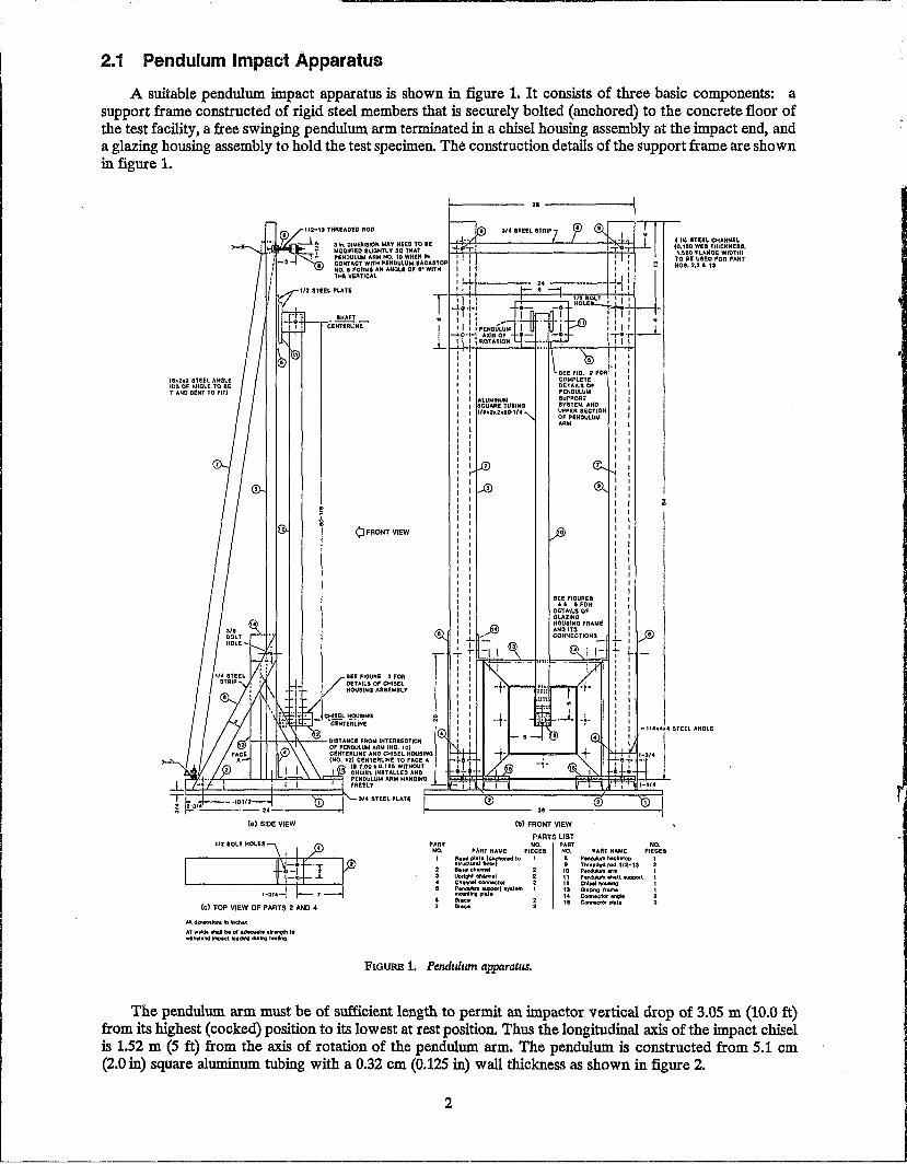
A suitable pendulum. impact apparatus is shown in figure 1. It consists of three basic components: a support frame constructed of rigid steel members that is securely bolted (anchored) to the concrete floor of the test facility, a free swinging pendulum. arm terminated in a chisel housing assembly at the impact end, and a glazing housing assembly to hold the test specimen. The construction details of the support frame are shown in figure 1.
IS.:h2 8TEEL AHOlE ~DS OF .,HOlE to BE T AND OE!NT TO FIT)
3 k OIW£~laION MAV NEED TO IE MODIFle.D IIRIGHTLY IIQ 1HA1 PENDULUM AAM NO. to WHEN IN CONTACT WI1H PENDULUM _"CKaTOp NO •• FORMS AN ANOLE 0' ,. WITH THE VERTICAL
SHAFT ceNTiRUNE
QFRONT VIEW
I
SEE FIOUAE 3 FOR
/
DETAILS OF CHISEl HOUItING 1oSSEM8LY P
CHISEL HOUSING
'a-------'"'i
" SEE FlO. 2 ;OR I
g~f:\tiT5F I PENDULUM I SUPPORT I ~;::~~E~~~ON I OF PENDULUM I ARa.4 I
I I I I I
I , I I I I I , I I I I I I I I I I , lI I I I I , I I I I
.. IN. SlUt. CHANHE!. Co, H!IIO WEll THICK",eaa, \.680. 'FLM60t WIO'")
TO "E UBED FOR ,.ART NOB. 2,3 & 13
-=-"'~,,-.,- ::::::~I::OM IHlERSECTmN r I ,.1(·414114 STEEL ANOlE I
of PENDUlUM ARU (NO. 10) CENTERLINE AND CHISEL HOUSING (NO, 12) CENTERLINE TO ""CE A
,
'5 h'Hrd~~ ~~a~~~~IJ~~~T f-''r---'-..L..L¥7''7''--'--=::;=t PENDULUM ARM HANalNO I~~~~~~----"';';~~~~~P:,.,....L
FREELY
):::::t=~===::)::==~==:l-.. 3/" snEL PUTE f==~==~~========::;~==~~
(a) SIDE VIEW
(e) TOP VIEW OF PARTS 2 AND 4
M~t.\oro&Iro,Inc.M.
AI wfle» thai be of a~t •• tr~ to wh""anclimoict ..,.dI!'lO rU~ t"l~
~---------------- o. ----------------~~
PART NO.
I PART NAME
(b) FRONT VIEW
PARTS LIST NO. PART
PIECes NO. 0 ... plat. C~.d to 1 a 'It~tUfalflnof) II B .. ech~ 10 Uoflyhl chinn.! \ \ Chl/'fMl connector 12 P~ ~t Ir""" 13 fI'IOWIItng pll'e '" ElrIC' 115 Bl'IC'
FIGURE 1. Pendldlan apparatus.
NO. PART NAME PIECES
PllI\dub'nb.ckltoe» Tll'lacled rOd 112-13 P.nduIutn arm p~ eMU wpQOI:t Chi." hOuM'O Gluing ItaIM Connector angle ~orpiat.
The pendulum arm must be of sufficient length to permit an impactor vertical drop of 3.05 m (10.0 ft) from its highest (cocked) position to its lowest at rest position. Thus the longitudinal axis of the impact chisel is 1.52 m (5 ft) from the axis of rotation of the pendulum. arm. The pendulum. is constructed from 5.1 em (2.0 in) square aluminum. tubing with a 0.32 cm (0.125 in) wall thickness as shown in figure 2.
2

116.2,2 ... LUMINUM
ANGLE
116 NONCONDUCTIVE
SP ... CER
BRONZE SHIM STOCK 0.010 THICK
FLAP FASTENED WITH TWO .. 6 SHEET MET ... L
SCREWS
FRONT VIEW OF MICROSWITCH AND FLAP MOUNTING
112 BOLT fIOLES. 4
P ... RT NO. 10 11 16 17 18 19 20 21 22 36
PARTS LIST
P ... RT N ... ME PondlM,xn Arm .PenduUn Shan Suppor1 Penduklm Shan SaBring" BraaslltJahlng Reinlorcemont Block Set Screw Mfcr08Wltch Rap Mk:roawltch Mount
NO. PIECES
1 1 1 2 2 1 2 1 1 1
~\ • .I..',. \":~---''''''I~/<t/
'l~'''~" 114 BOLT HOLES. 4 ., • . (BOL TS USED SHOULD BE
~ t" 2-112 In. LONG)
.~ C) STEEL ~EINFORCEMENT '" L.t BLOCK (TO FIT r, ... UGL Y : 'f: IN ... LUMINUM SQUARE
I I TUBING) I : I
.:J,,~~ : ! l ' I .., I ,
I , , I
3' ,
j : : , , , , I ,
,\~: ' , ' I ' , ,
'\ 8-32 SET SCREW
\ bl'~ i"-< ~'-1I8 01 ....
~1I2BDRE -1-3/4DIA
112 DRILL HOLE
118 x 2 X 2X 60-114 ... LUMINUM SQU ... RE
TUBING
AI _alona In Incho.
All welda shall bo of adeQUate strength to Withstand Impact loading during lostlng.
'" Aluminum alloy 6063-T52 uaed.
*' III Boarlngs wore slnolo row, radial, Inch dkoonsloooJ, extra light sarlos, retainer type, wtth two 8t~elds. Dimensions: bore = 0.5000 In. I 0.0. = 1.125 In.,
width c 0.31251 •• Examplos of two mnnufacturers aro! Fafnir (No. S5KDD) and
Now Depa,'u,e (No. 77R6).
FIGURE 2. PenduJwn support system and upper section of pendldlun ann.
The pendulum arm requires a low-friction bearing pivot system, also shown in figure 2. It is critical that the pendulum arm swing through its arc with a minimum of lateral sway to ensure a reproducible impact location.
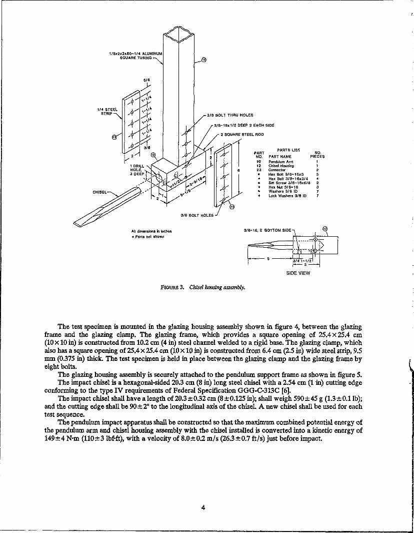
The construction details of the impact chisel housing and its attachment to the free end of the pendulum arm are shown in figure 3. The chisel housing pern,tits a new chisel to be firmly installed for each specimen to be tested.
3
... 11 dimension. In Inches
'" Parts nol shown
'0
3/8 BOLT THRU HOLES
31l' SOL THOLES
3/B-16X 1/2 DeEP 2 e"CH SIDE
2 SQUARE STEEL ROD
PART PARTS liST
NO. PART NAME 10 Pendulum Arm 12 Chisel HOIlslng 23 COmeclO(
'" Hex Bo~ 3/8-16x3
'" Hex Boll 3/8-16x3/4
'" SIll Scre .. 3/8-18x5/8
'" Hex Nul 3/8-18
'" Washers 318 10
'" lock Washers 3/8 10
3/8-16,2 BOTTOM SlOE
SIDE VIEW
FIOURE 3. Chisel housing assembly.
NO. PIECES
1 1 2 3 4 2 3 7 7
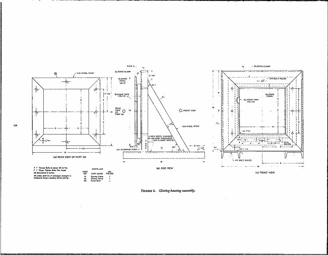
The test specimen is mounted in the glazing housing assembly shown in figure 4, between the glazing frame and the glazing clamp. The glazing frame, which provides a square opening of 25.4x25.4 cm (lOX 10 in) is constl'Ucted from 10.2 cm (4 in) steel channel welded to a rigid base. The glazing clamp, which also has a square opening of 25.4 X 25.4 cm (10 x 10 in) is constructed from 6.4 cm (2.5 in) wide steel strip, 9.5 m.m (0.375 in) thick. The test specimen is held in place between the glazing clamp and the glazing frame by eight bolts.
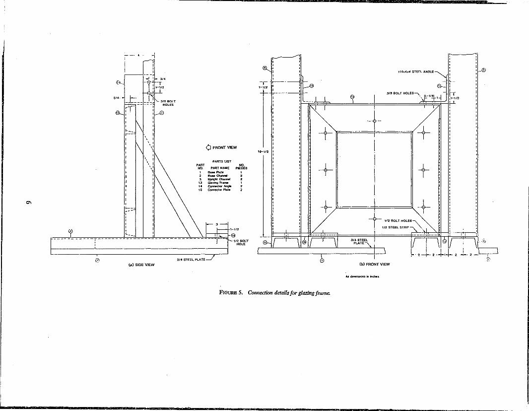
The glazing housing assembly is securely attached to the pendulum support frame as shown in figure 5. The impact chisel is a hexagonal-sided 20.3 cm (8 in) long steel chisel with a 2.54 cm (1 in) cutting edge
conforming to the type IV requirements of Federal Specification GGG-C-313C [6]. The impact chisel shall have a length of20.3±0.32 cm (8 ± 0.125 in); shall weigh 590±45 g (1.3±0.1Ib);
and the cutting edge shall be 90 ± 2° to the longitudinal axiis of the chisel. A new chisel shall be used for each test sequence.
The pendulum impact apparatus shall be constructed so that the maximum combined potential energy of the pendulum arm and chisel housing assembly with the chisel installed is converted into a kinetic energy of 149±4 N'm (110±3Ibfoft), with a velocity of 8.0±0.2 mls (26.3±0.7 ft/s) just before impact.
4
va
t--
Tn'.
~-t-~ -tI
---1----- ~~ 5 ~ i
T
15 -----~
Cal REAR VIEW OF PART 30
rr
! I
17-;'2 5 ! \
~~Ttt-~ IS , !
~
PARTS LIST
FACE A_
" GLAZING CLAMP -
/~c$ lr
GLAZING -T-PANEL 12x12
GLAZING TAPE 1I8x1l2 -..:::- -
-j.
REAR
~~w [) 15
PART 30
1 _U@, 3/8-1 !-
1/4 ALUMINUM STRIP-' L ___ _
, I I- ~ __ _
., on
'"
2-1/8
18
Cb) SIDE VIEW
\:1 FRONT VIEW
3/6 STeEL STRIP
T ~!
11 I I I I I
18 111 :1
(,',-J:I a I
(,~ ,"'" GLAZING CLAMP
--=-:-~ ~ -3'8 BOLT HOLES/: ________________ , _____ - I
,"~----ulm-\n--u::--~: :-0]: :
Ii , , I I
I .e.! .. , ,
- GLAZING TAPE 1/8.1/2
J I t I I I I , I I
I I I I I I I :: i15
: I I I I I I I
-:-y' I I
, ' I I I I
-t-
I: --- 5 I I :Jl'5 , I I f I I i l;f ~T'p I' ,
~I I.
: · ' 3~1:~~-~~~:~~I~~~1~::.:~~T~- i ! : _ _ 4 -------I I ~2-1I' _~ "- 3/16
"" ~y"+<~;.---n----.-:-I-.-_~:-:--:-=-::" '.~ ~ --Lhr. ! 0 ~ I,.. '
1,\ F . II'
i L..
'''-112 BOLT HOLES
~--18
~~---~ -----j
T • Torwe Bob to about 28 in-tbL F • ~ l'it;tIIen Softs (No Toob) AI dma.-.;oo. i1 r.ches PART NO.
NO. PART NAME Dt~rl:C'
13 Glazng Frame ..... .,Mdt ahal be of adequate strength to (C) FRONT VIEW wtthetand mpac;t k:ladlng during leatlng.. 30 Gla=gCl"""
35 Panel Seat
FIGURE 4. Glazing housing assembly.
0\
(.\
L_______ _______ _
1--
I 1---.--I I I I I I
"--
. - -l
(a) SIDE VIEW
PART NO_
1
• 3 13 14 15
3/4 STEEL PLATE
Q FRONT VIEW
PARTS LIST
PART NAME BaM Plata !laM CIumoI IJoriohI CIwroo! Glazing Frame Comector Arge Comector Plat.
NO. PIECES
1
• 2
1/2 BOLT HOLE
.-1-112
18-1/2
11
1/4)( .. ,,4 STEEL ANGLE ~
I t.._ 1 I --r- 3'8aOLTHOLES-\ r'f '1Jh : l! ~ ). '~ G12
: lk : : A1 I I I I
11 II
+" /+ . ~ 11 .
+ + + + t- '\
- 112 BOLT HOLES
• 112 STEEL STRIP ~
(b) FRONT VIEW
Ail dmensions ... inches
FIGURE 5. Connection details for glazing frame.
~1-0 I
I
, '~l
2.2 Heating Torches
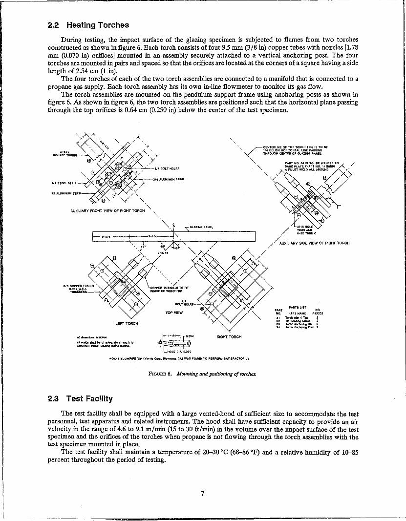
During testing, the impact surface of the glazing specimen is subjected to flames from two torches constructed as shown in figure 6. Each torch consists of four 9.5 mm (3/8 in) copper tubes with nozzles [1.78 mm (0.070 in) orifices] mounted in an assembly securely attached to a vertical anchoring post. The four torches are mounted in pairs and spaced so that the orifices are located at the corners of a square having a side length of 2.54 cm (1 in). .
The four torches of each of the two torch assemblies are connected to a manifold that is connected to a propane gas supply. Each torch assembly has its own in-line flowmeter to monitor its gas flow.
The torch assemblies are mounted on the pendulum support frame using anchoring posts as shown in figure 6. As shown in figure 6, the two torch assemblies are positioned such that the horizontal plane passing through the top orifices is 0.64 cm (0.250 in) below the center of the test specimen.
STEEL SOUARE TUBING -
" V CENTERLINE OF TOP TORCH TIPS IS TO BE 11 .. BELOW HORIZONT Al LINE PASSiNG THROUQH CENTER OF OLAZING PANEL
1/4 STEEL STRIP
'" ~...-y""""~~3/8 ALUMINUM STRP
" "
~.~ ,GLAZINGPAHEL /'/~~H~';,E
f- . 8-32 THAU C
'-31' ---1'1-,.--3-"4 '" ./ ," ./' AUXILIARY SIDE VIEW ()f RIGHT TORCH
, .. ~, "'6' ••• '\.
"< 0-011< '\. A /'
LEFT TORCH-
A.!_"_ AI weldla an.!I ~ of .de>qJat. ,trength to wtthItand ~c' lo.dIng cbtng , .. tlng.
// 0'~> " / ~ , " ,
'./ COf'I'ER TUIING IS TO FIT IH8IDE OF TORCH TIP ~
.0L~I.kES--V-~. • ",,,,
'y~'Z' TOP VIEW
RIGHT TORCH
~OX-3 BLOWPIPE TIP (Y",IHo Corp .. FIdvnonct, CAl WAS FOUND TO PERFORM SATISFACTORILY
FIGURE 6. Mounting and positioning of torches.
PART NO.
PART8llST NO.
PART NAME P1ECES
31 Torc:hwllh"~ 2 3' no_c:a.n.. • 33 TOfch Anc:hI::Img S. 2 3. T ___ •
2.3 Test Facmty
The test facility shall be equipped with a large vented-hood of sufficient size to accommodate the test personnel, test apparatus and related instruments. The hood shall have sufficient capacity to provide an air velocity in the range of 4.6 to 9.1 m/min (15 to 30 ft/min) in the volume over the impact surface of the test specimen and the orifices of the torches when propane is not flowing through the torch assemblies with the test specimen mounted in place.
The test facility shall maintain a temperature of 20-30 °C (68-86 OF) and a relative humidity of 10-85 percent throughout the period of testing.
7

=
2.4 Instrumentation
2.4.1 Anemometer
A hot-wire anemometer is required to measure the air flow velocity over the impact surface of the test specimen with the hood vent in operation. The anemometer shall have an accuracy of ±0.6 m/min (±2 ft/min).
2.4.2 Gas Flow Meters
Two calibrated in-line gas flowmeters are required to reguiate the propane gas flowing through each of the two torch assemblies. The flowmeters shall be adjustable to 0.27 ± 0.014 m3/hr (9.5 ± 0.5 ftl /h) at 21 °c (70 OF) and 760 torr (14.7 psi) absolute pressure using commercial-grade propane gas and shall maintain that flow rate throughout the test. Calibration shall be traceable to the National Bureau of Standards.
2.4.3 Event Recorder
A strip chart recorder is required to record the number and time hi'>tory of impacts applied to each test specimen. The recorder shall have a chart speed of approximately 12.7 cm/min (5 in/min), accurate to within 2 percent. A voltage source compatible with the recorder input is connected to the recorder through a microswitch mounted on the impact apparatus to provide a spike each time the pendulum impacts the test specimen. In addition, a stopwatch shall be used to determine the total time that the specimen is exposed to the flame from the torches.
2.4.4 Velocity Measuring Device
An optically-activated chronometer is required to determine the velocity of the pendulum impact chisel just prior to striking the test specimen. This device must measure and display the time interval for the impact chisel to move between two points 3.81 cm (1.5 in) apart with sufficient accuracy to enable the determination of the velocity to within ± 15.2 cm/s (±0.5 ft/s). The velocity shall be calculated as the distance between the two points [3.81 cm (1.5 in)] divided by the time required to trav.el that distance.
2.4.5 Audible Interval Timer
The time between impacts must be carefully regulated during each test sequence. An interval timer that can be reset to provide a specific time interval of 3.0 to 7.0 s is required. The timer shall produce an audible signal at the end of the time interval. The audible signal shall be of sufficient sound level to be clearly heard at a distance of at least 6.1 m (20 ft) during the impact testing.
3. SPECIMEN PREPARATION
The test specimens shall consist of 30.5 cm (12 in) square panels of the glazing material. Inspect each test panel for flaws. In the event that a panel is obviously defective, discard it and select a
replacement pane1. Measure and record the length, width, and thickness of each panel and note this information on a data sheet. The following information shall also be noted on the data sheet:
a) Name of manufacturer. b) Manufacturer identification number/name of the glazing material. c) Month and year of manufacture. d) A listing of the materials and their thicknesses that comprise the specimen, starting with the nonim
pact surface. e) Date of test and time of day test begins. Establish a random test sequence for the test specimens, and number each panel accordingly. Record the
test specimen number on a label affixed near one bottom corner of the panel on the side that will not be impacted.
4. TEST METHOD
4.1 Test Setup
Install the pendulum impact apparatus, with the glazing housing assembly rigidly attached to it, in a properly vented test facility. Insert an impact chisel into the chisel housing assembly with the cutting edge
8
=
IT
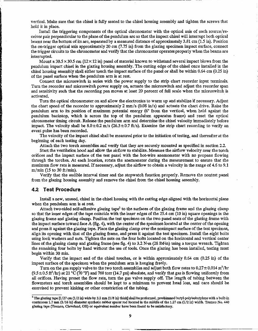
vertical. Make sure that the chisel is fully seated to the chisel housing assembly and tighten the screws that hold it in place.
Install the triggering components of the optical chronometer with the optical axis of each source/receiver pair perpendicular to the plane of the pendulum arc so that the impact chisel will interrupt both optical beams near the bottom of its arc, separated by a measured distance of approximately 3.81 cm (1.5 in). Position the on-trigger optical axis approximately 20 cm (7.75 in) from the glazing specimen impact surface, connect the trigger circuits to the chronometer and verify that the chronometer operates properly when the beams are interrupted.
Mount a 30.5 x 30.5 cm (12 x 12 in) panel of material known to withstand several impact blows from the pendulum impact chisel in the glazing housing assembly. The cutting edge of the chisel once installed in the chisel housing assembly shall either touch the impact surface of the panel or shall be within 0.64 cm (0.25 in) of the panel surface when the pendulum arm is at rest.
Connect the microswitch in series with the power supply to the strip chart recorder input terminals. Turn the recorder and microswitch power supply on, actuate the microswitch and adjust the recorder span and sensitivity such that the recording pen moves at least 20 percent of full scale when the microswitch is activated. .
Turn the optical chronometer on and allow the electronics to warm up and stabilize if necessary. Adjust the chart speed of the recorder to approximately 2 mm/s (0.08 in/s) and actuate the chart drive. Raise the pendulum arm to its position of maximum potential energy (60 from the vertical, when held against the pendulum backstop, which is across the top of the pendulum apparatus frame) and reset the optical chronometer timing circuit. Release the pendulum arm and determine the chisel velocity immediately before impact. The velocity shall be 8.0±0.2 m/s (26.3±0.7 fils). Examine the strip chart recording to verify an event pulse has been recorded.
The velocity of the impact chisel shall be measured prior to the initiation of testing, and thereafter at the beginning of each testing day.
Attach the two torch assemblies and verify that they are securely mounted as specified in section 2.2. Start the ventilation hood and allow the airflow to stabilize. Measure the airflow velocity near the torch
orifices and the impact surface of the test panel with the hot-wire anemometer with no propane flowing through the torches. At each location, rotate the anemometer during the measurement to ensure that the maximum flow rate is measured. If necessary, adjust the airflow to obtain a velocity in the range of 4.6 to 9.1 m/min (15 to 30 fi/min).
Verify that the audible interval timer and the stopwatch function properly. Remove the nontest panel from the glazing housing assembly and remove the chisel from the chisel housing assembly.
4.2 Test Procedure
Install a new, unused, chisel in the chisel housing with the cutting edge aligned with the horizontal plane when the pendulum arm is at rest.
Attach two-sided self-adhesive glazing tape2 to the surfaces of the glazing frame and the glazing clamp so that the inner edges of the tape coincide with the inner edges of the 25.4 cm (10 in) square openings in the glazing frame and glazing clamp. Position the test specimen on the two panel seats of the glazing frame with the impact surface toward face A (fig. 4), with the center of the specimen located at the center of the opening and press it against the glazing tape. Place the glazing clamp over the nonimpact surface of the test specimen, align its opening with that of the glazing frame, and press it against the test specimen. Install the eight bolts using lock washers and nuts. Tighten the nuts on the four bolts located on the horizontal and vertical center lines of the glazing clamp and glazing frame (see fig. 4) to 3.2 N'm (28 Ibf'in) using a torque wrench. Tighten the remaining four bolts by hand without the use of tools. Once the glazing has been installed, testing must begin within 30 min.
Verify that the impact end of the chisel touches, or is within approximately 0.64 cm (0.25 in) of the impact surface of the specimen when the pendulum arm is hanging freely.
Turn on the gas supply valve to the two torch assemblies and adjust both flow rates to 0.27 ± 0.014 m3/hr (9.5 ± 0.5 ff /hr) at 21 °C (70 OF) and 760 torr (14.7 psi) absolute, and verify that gas is flowing uniformly from all orifices. Having preset the flow rate, turn the gas valve supply off. The length of tubing between the flowmeters and torch assemblies should be kept to a minimum to prevent head loss, and care should be exercised to prevent kinking or other constriction of the tubing.
2 The glazing tape [1/27 cm (1/2 in) wide by 3.1 mm (1/8 in) thick] shall be preformed, preshimmed butyl-polyisobutylene with a built-in continuous 1.7 mm (1/16 in) diameter synthetic rubber spacer rod located in the middle of the 1.27 cm (1/2 in) width. Tremco No. 440 glazing tape (Tremco, Cleveland,OH) or equivalent number have been found to be satisfactory.
9
Set the audible interval timer as appropriate for the operator controlling the impact pendulum and raise the pendulum arm to its uppermost position. Actuate the recorder chart drive. Turn the gas supply on and immediately ignite the torches using a prelit ignition stick (a long metal rod with a flammable material at one end).
Immediately upon ignition of the torches actuate the stopwatch and activate the audible interval timer. Release the pendulum arm when the signal from the intel'val timer is heard.
At the sound of impact, reset and start the audible interval timer, catch the pendulum arm upon rebound from the impact, and return it to the fully raised position. When the operator controlling the pendulum arm hears the signal from the audible interval timer, the pendulum is once more released and the audible interval timer is reset.
The test specimen shall be subjected to repeated impacts until the chisel penetrates through the test specimen; i.e., the end of the impact chisel clearly protrudes through the nonimpact surface of the test specimen.
The time interval between impacts shall be no more than 8.5 nor less than 5.5 s, and at least half of the time intervals shall be between 5.5 and 7.0 s for each specimen tested. Recognize, however, that precise control of the impact intervals is difficult to achieve, particularly when specimens are penetrated after only five or less impacts.
Upon penetration, stop the stopwatch, turn off the gas to the torches, and stop the strip chart. Using protective gloves, remove the impactor from the test specimen immediately (to prevent the possi
bility of the chisel becoming permanently embedded in the glazing specimen), remove the test specimen from the glazing housing assembly, and then place the pendulum arm in the at rest (low potential energy) position. The total number of impacts as determined from the strip chart recording and the elapsed time displayed by the stopwatch shall be recorded on the data sheets.
5. DISCUSSION
Two individuals are required to implement the test procedure presented in this report, and teamwork is essential. It is not possible to specify the exact time setting for the audible interval timer to ensure that the impacts are spaced as required for this is dictated by the reaction times of the individuals controlling the interval timer and the pendulum arm. The test engineers that developed the test method found a time setting of approximately 5 s to be suitable for them.
The nature of the test is such that safety is a major concern and it is essential that anyone attempting to implement the test procedure establish and follow suitable safety procedures. Hard hats and safety shoes should be worn when assembling the impact apparatus. During testing, a mandatory clear zone must be established to ensure a safe distance around the full plane of the impactor pendulum arc and the flames from the torches. This is of particular concern during the presence of visitors and observers.
All test personnel must wear full face protection and hard hats. If there is any possibility that the test specimens can produce noxious gases when exposed to the flames from the torches, appropriate respiratory protection should also be used. The individual controlling the pendulum arm will have to operate from an elevated position. The nonskid ladder that is used must have nonskid stairs and be equipped with siderails. It is also important to light the torches as quickly as possible once the gas supply is turned on, for it would be possible to create an explosive gas mixture if the propane were allowed to flow freely for an extended time prior to ignition.
Both of the test personnel must be thoroughly familar with all aspects of the test procedure. During testing of a glazing specimen that resists a large number of impacts prior to penetration, it will be necessary for the person observing the glazing panel and operating the interval timer to change functions with. the person controlling the pendulum arm. The changing of functions must be carefully coordinated and it is essential to take proper safety precautions, even if it results in extending the interval between impacts beyond the 8 s maximum specified in section 4.2.
The design of the pendulum impact apparatus is such that it should not be used to test glazing specimens that are thicker than 5.1 cm (2 in).
The tests that were conducted to develop the test method generally used a sample of two or three specimens of each type of glazing. This appeared to be a sufficient sample size in some cases. There were, however, some instances in which the scatter in the data for certain types of glazing was such that a larger sample size would be required to accurately characterize the penetration resistance of the glazing.
10
111&
i I
j

6. REFERENCES
[1] Knab, L. I., Fischler, S., Clifton, J. R., Waters, N. E. Development of a standard test method for high-security glazing to resist mechanical impact and heat applications. NIJ Report 300-85. National Institute of Justice, U.S. Department of Justice, Washington, DC 20531. 1986 November.
[2] Ballistic resistant protective materials. NIJ Standard-0108.01. National Institute of Justice, U.S. Department of Justice, Washington, DC 20531; 1985 September.
[3] Physical security of door assemblies and components. NILECJ-STD-0306.00. National Institute of Justice, U.S. Department of Justice, Washington, DC 20531; 1976 May.
[4] Physical security of window units. NIJ Standard-0316.00. National Institute of Justice, U.S. Department of Justice, Washington, DC 20531; 1980 August.
[5] Physical security of sliding glass door units. NIJ Standard-0318.00. National Institute of Justice, U.S. Department of Justice, Washington, DC 20531; 1980 August.
[6] Federal specifications for chisels, hand: cape, diamond point, cold, round nose, and side cutting. Fed. Spec. GGG-C-313C (GSA-FSS) dated August 16,1976. General Services Administration, Washington, DC 20405.
11
nm ..