TEST LOSS-OF-COOLANT ACCIDENT CONDITIONS*/67531/metadc686704/...TEST PLAN FOR HIGH-BURNUP FUEL...
14
. * . ~o~&%/eL;Io~ -8 TEST PLAN FOR HIGH-BURNUP FUEL CLADDING BEHAVIOR UNDER LOSS-OF-COOLANT ACCIDENT CONDITIONS* JbW t 6 t997 OSTI H. M. Chung, L. A Neimark, and T. F. Kassner Energy Technology Division Argonne National Laboratory Argonne, IL 60439 The submllld mlnurcript has been created by the Univcrrity of Chicago u operalor of Argonne National hboruory CArgonnc”) undcr ConWac1 No. W-31-109- ENQ-311 wilh (he U.S. Depumcni of Energy. Th US. Governmen1 retains lor IUelf. and olhen acling on its behalf. a paid-up. noncxclurlve, irrevocable worldwide licenre In raid utlele lo rcproducc. prepare dcrlvallve works, dirtribute copies lo !be public, and perform publicly and dlrplay publicly. by or on behalf of (he Dnvernmrnt October 1996 Paper presented at 24th Water Reactor Safety Information Meeting, October 21-23, 1996, Bethesda, MD. *Work supported by the Office of Nuclear Regulatory Research, U.S. Nuclear Regulatory Commission.
Transcript of TEST LOSS-OF-COOLANT ACCIDENT CONDITIONS*/67531/metadc686704/...TEST PLAN FOR HIGH-BURNUP FUEL...
. * .
~ o ~ & % / e L ; I o ~ -8 TEST PLAN FOR HIGH-BURNUP FUEL CLADDING BEHAVIOR UNDER
LOSS-OF-COOLANT ACCIDENT CONDITIONS*
JbW t 6 t997 O S T I
H. M. Chung, L. A Neimark, and T. F. Kassner Energy Technology Division
Argonne National Laboratory Argonne, IL 60439
The submllld mlnurcript has been created by the Univcrrity of Chicago u operalor of Argonne National hboruory CArgonnc”) undcr ConWac1 No. W-31-109- ENQ-311 wilh (he U.S. Depumcni of Energy. Th US. Governmen1 retains lor IUelf. and olhen acling on its behalf. a paid-up. noncxclurlve, irrevocable worldwide licenre In raid utlele lo rcproducc. prepare dcrlvallve works, dirtribute copies lo !be public, and perform publicly and dlrplay publicly. by or on behalf of (he Dnvernmrnt
October 1996
Paper presented at 24th Water Reactor Safety Information Meeting, October 21-23, 1996, Bethesda, MD.
*Work supported by the Office of Nuclear Regulatory Research, U.S. Nuclear Regulatory Commission.

DISUAIMER
Portions of this document may be illegible in electronic image products. Images are produced from the best available original document.
TEST PLAN FOR HIGH-BURNUP FUEL BEHAVIOR UNDER LOSS-OF-COOLANT ACCIDENT CONDITIONS*
H. M. Chung, L. A Neimark, and T. F. Kassner Argonne National Laboratory
Argonne, IL 60439
ABSTRACT
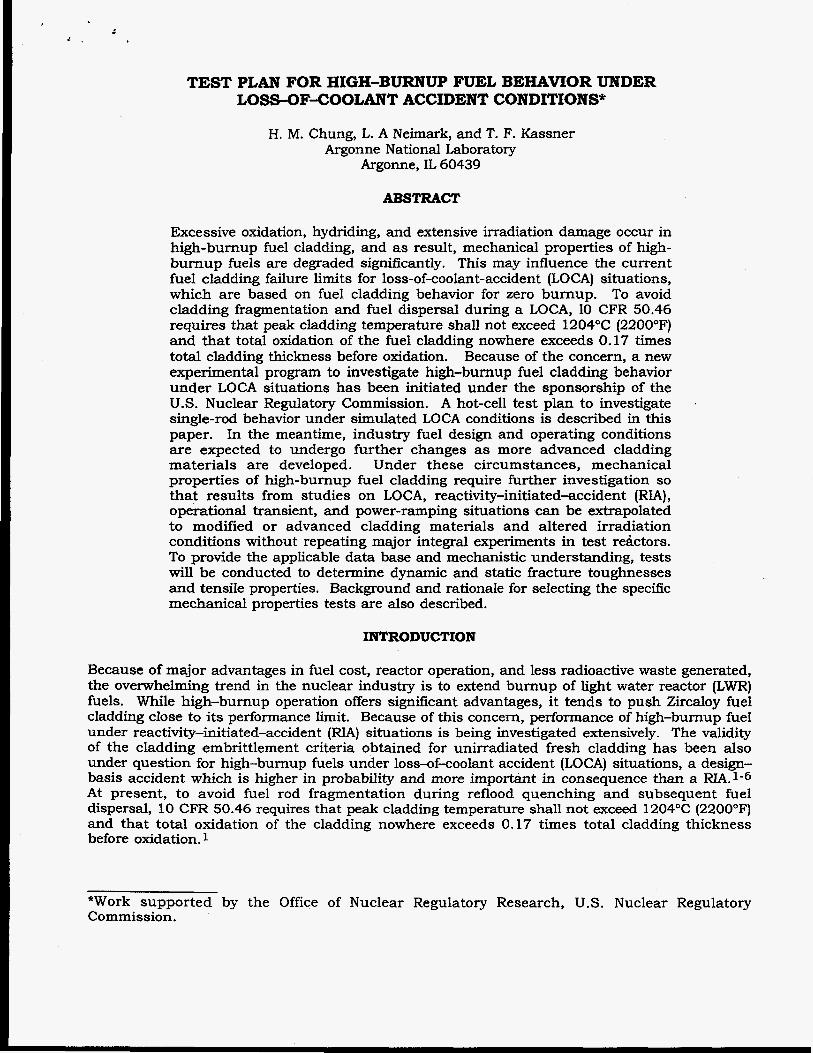
Excessive oxidation, hydriding, and extensive irradiation damage occur in high-burnup fuel cladding, and as result, mechanical properties of high- burnup fuels are degraded significantly. This may influence the current fuel cladding failure limits for loss-of-coolant-accident (LOCA) situations, which are based on fuel cladding behavior for zero burnup. To avoid cladding fragmentation and fuel dispersal during a LOCA, 10 CFR 50.46 requires that peak cladding temperature shall not exceed 1204°C (22OOOF) and that total oxidation of the fuel cladding nowhere exceeds 0.17 times total cladding thickness before oxidation. Because of the concern, a new experimental program to investigate high-burnup fuel cladding behavior under LOCA situations has been initiated under the sponsorship of the U S . Nuclear Regulatory Commission. A hot-cell test plan to investigate single-rod behavior under simulated LOCA conditions is described in this paper. In the meantime, industry fuel design and operating conditions are expected to undergo further changes as more advanced cladding materials are developed. Under these circumstances, mechanical properties of high-burnup fuel cladding require further investigation so that results from studies on LOCA, reactivity-initiated-accident (RIA), operational transient, and power-ramping situations can be extrapolated to modified or advanced cladding materials and altered irradiation conditions without repeating major integral experiments in test retlctors. To provide the applicable data base and mechanistic understanding, tests will be conducted to determine dynamic and static fracture toughnesses and tensile properties. Background and rationale for selecting the specific mechanical properties tests are also described.
INTRODUCTION
Because of major advantages in fuel cost, reactor operation, and less radioactive waste generated, the overwhelming trend in the nuclear industry is to extend burnup of light water reactor (LWR) fuels. While high-burnup operation offers significant advantages, it tends to push Zircaloy fuel cladding close to its performance limit. Because of this concern, performance of high-burnup fuel under reactivity-initiated-accident (RIA) situations is being investigated extensively. The validity of the cladding embrittlement criteria obtained for unirradiated fresh cladding has been also under question for high-burnup fuels under loss-of-coolant accident (LOCA) situations, a design- basis accident which is higher in probability and more important in consequence than a RIA.1-6 At present, to avoid fuel rod fragmentation during reflood quenching and subsequent fuel dispersal, 10 CFR 50.46 requires that peak cladding temperature shall not exceed 1204OC (2200OF) and that total oxidation of the cladding nowhere exceeds 0.17 times total cladding thickness before oxidation. 1
*Work supported by the Office of Nuclear Regulatory Research, U.S. Nuclear Regulatory Commission.

At high burnup, in addition to extensive irradiation damage, Zircaloy cladding is susceptible to excessive oxidation and hydriding, usually in the form of uniform breakaway corrosion in PWRs and nodular corrosion in BWRs. For some type of Zircaloy-4 cladding, maximum oxide layer thickness during normal operation to a bumup of =60 GWd/t in a PWR appears to be close to or exceeds =lo0 pm, leaving little margin for additional oxidation during a LOCA to remain below the 17% oxidation limit.
In the meantime, it is not clear whether high-temperature oxidation kinetics of high-bumup cladding applicable to LOCA situations are similar to those of unirradiated cladding. Although data base on high-temperature oxidation kinetics of high-bumup cladding would be required in the evaluation model of emergency-core-cooling-system (ECCS) acceptance criteria3 for high burnup operation, only very limited results have been reported in the literature .4 Surprisingly, the initial results reported in Ref. 4 indicate that high-temperature oxidation kinetics of high- burnup cladding may be faster than the counterpart kinetics applicable to unirradiated or low- burnup cladding. Although further investigation is necessary to confirm the initial finding, higher oxidation rates at high temperatures cannot be ruled out considering the characteristic microstructure of high-burnup cladding, i.e., high porosity of the thick breakaway oxide layer and extensive hydriding of the Zircaloy metal underneath the oxide.
High-burnup fuel cladding is also characterized by significant degradation of ductility and fracture toughness, which is attributed to formation of dense hardening centers in the a-phase Zircaloy. The hardening centers are usually associated with excessive oxidation, hydriding, and extensive irradiation damage that are unique to high-burnup operation. Under some conditions, brittle-type failures are produced as a result. Some of the hardening centers (e.g., impurity-irradiation damage complexes) produced in the high-burnup cladding may not be fully annealed out during the high-temperature excursion in a LOCA situation, and as a result, cladding failure by subsequent reflood thermal shock could be influenced adversely. Because of these concerns, a new experimental program to investigate high-burnup fuel cladding behavior under LOCA situations has been initiated under the sponsorship of the U.S. Nuclear Regulatory Commission. The primary objective of this paper is to identify and describe hot-cell test plans that are most suitable to determine the high-burnup fuel behavior under LOCA situations.
In the meantime, industry fuel design and operating (irradiation) conditions are expected to undergo further changes as more advanced cladding materials are developed. Under these circumstances, mechanical properties of high-bumup fuel cladding require further investigation so that results from LOCA and RIA studies can be extrapolated to modified or advanced cladding materials and altered irradiation conditions without repeating major integral experiments in test reactors. Of particular importance are the effects of alloy chemistry, fast neutron fluence, oxidation, hydriding, test temperature, ductilebrittle transition phenomenon, and strain rate on ductility and fracture toughness applicable to LOCA, RIA, power ramping, and other transient situations. At present, the data base and mechanistic understanding in these areas are very limited. To provide applicable data base and mechanistic understanding, parallel tests will be also conducted in this program to determine mechanical properties of several types of high- burnup cladding. Hot-cell test plans and rationale for selecting the specific mechanical properties tests and microstructural analyses are also described in this paper.
LOCA SIMULATION - BASIC CONSIDERATIONS
The focus of this experimental program is to provide (1) a sufficient data base, (2) good correlation of test results with post-test microstructural analyses, and (3) mechanistic understanding applicable to high-burnup fuel under LOCA situations. Specifically, the following questions will be addressed:
(A) Is the 17% oxidation limit valid at high burnup?
- 2 -

(B) What are the key metallurgical and thermal-hydraulic factors that influence fuel
(C) What is the effect of extensive hydriding in high-burnup cladding? (D) What are the criteria that can predict best the high-burnup cladding integrity under
conditions of (1) reflood quenching thermal shock, (2) post-LOCA handling, and (3) combined seismic load and thermal shock?
(E) Are such criteria applicable regardless of the type of cladding material (e.g., standard Zircaloy, low-tin Zircaloy, Zirlo, and other non-Zircaloy materials), cladding geometry (initial thickness, degree of ballooning and rupture), and irradiation condition (temperature, burnup)?
(F) What are the high-temperature oxidation kinetics that can predict best the oxidation behavior of high-burnup cladding under LOCA situations?
failure (during LOCA) at high burnup?
To understand high-burnup effects, it is useful to review the background of the current 17% oxidation limit5 and evaluate significance of other alternative embrittlement criteria developed for unirradiated fresh cladding.2 Essentially, the 17% oxidation criterion was established on the basis of the thermal-shock data reported by Hesson et al. in the early 1970s.5 The data were obtained on relatively thick unirradiated Zircaloy-2 BWR cladding specimens (thickness = 1,000 pm) in which oxide layer thickness was negligible prior to exposure to simulated LOCA transients. After oxidation at >1300"C, thermal-shock tests were conducted by quenching the heavily oxidized specimens directly in cold water. The isothermal oxidation temperatures were, however, considerably higher than the current peak temperature limit of 1204°C (22OOOF).
Compared to the simulated LOCA conditions of Hesson et al., high-burnup PWR fuel cladding under LOCA situations is believed to exhibit several important variations in thermal-hydraulic and metallurgical parameters. These are illustrated schematically in Figs. 1 and 2, respectively. To begin with, thickness of modern PWR cladding is only 550-625 pm. And, as indicated in the time-temperature curve in Fig. 1, ballooning and rupture occur in a high-burnup cladding during the heatup phase. Therefore, cladding wall thickness will be reduced signifkantly in the rupture region. This effect, compounded by the effects of smaller initial wall thickness and thicker oxide layer from high-burnup operation, tends to produce significantly thinner load-bearing f!-phase in cladding at the time of rewetting (Fig. 2). More realistic heatup rates applicable to high-burnup fuel wil l be also evaluated and simulated in the LOCA test. I
oa U
; E
120 I E
3 CI
I?!
Peak Temperature 2200°F
Cladding Balloon and
Rupture
Direct Quench
Thermal Shock
0 1 5 1 t Time (s)
Two-Phase Cooling
Bottom Flood
rhermal Shock
0 1900
Figure 1.
llhistration of cladding temperature us. cime and
shock under a simulated U)CA condition
quenchingthemzal
160 20
- 3 -

Another important factor is the relatively slower two-phase cooling. The slow cooling in the mixture of steam and water vapor precedes the thermal shock which is produced when the film boiling collapses and rewetting of the hot oxide surface occurs. The rewetting temperature, measured on heavily oxidized unirradiated Zircaloy-4 specimens, has been reported to be lower than =650°C.2 Therefore, the magnitude of the thermal-shock stress will be influenced significantly by the mode of quenching, as well as by cladding thickness.
OXIDE ALPHA PRIOR BETA
Rgure 2.
schematic iUustration of microstructure of high-bump Zircaloy-4 cladding expected at
during reflood
LOG4 situations.
rime of thermal shock
quenchingunder
Cracks H ydrihes i
The Widmannstaetten grain structure and the morphology and distribution of hydrides in the loading-bearing transformed-p-phase layer are also strongly influenced by cooling rate of the p- phase at >815"C (Fig. 2). Under direct quenching, hydride precipitation in the transformed P phase is minimal. Hydrogen uptake and hydride precipitation are believed to play an important role in the failure behavior of high-burnup cladding; therefore, both types of simulated LOCA tests will be conducted, Le., direct fast quenching and thermal shock at 1700°C following the slower controlled cooling (Fig. 1).
Effects of fine microstructural features of the oxide- and a-phase layers and the morphology and distribution of hydrides in the a-phase cladding are believed to be only secondary in influencing the failure behavior during reflood quenching. However, a thick oxide layer such as that depicted in Fig. 2 will significantly reduce thermal conduction across the cladding wall at the time of quenching. This will produce an insulating effect which is conducive to smaller temperature differential across the thickness of the transformed-P-phase layer, thereby reducing the magnitude of thermal shock under otherwise similar conditions.
The thermal-shock-failure data reported by Hesson et al.5 are shown in Fig. 3, together with similar data reported from direct fast quenching experiments conducted on unirradiated Zir~aloys.2~~~6 Results in the figure shows that the 17% oxidation criterion is not consistent with the peak temperature limit of 1204°C (2200°F). That is, the 17% oxidation criterion is significantly conservative at 1204"C, whereas it is reasonably accurate for peak oxidation temperatures
- 4 -

I * ..
>1300°C. In view of this, most LOCA thermal-shock tests on high-burnup fuel cladding will be conducted in this program for peak oxidation temperatures <13OO0C.
The equivalent cladding reacted (ECR) parameter is a relative oxidation parameter. Therefore, accuracy of a failure criterion based on ECR is subject to variations in not only peak oxidation temperature but also cladding thickness (i.e., variations due to initial thickness, ballooning, and rupture). Consequently, several failure criteria based on more fundamental metallurgical parameters were developed in a previous investigation.2 An example of such criteria is that based on the absolute thickness of the load-bearing transformed P-phase of the cladding. In Fig. 4, the ECR data reported in Refs. 2 and 4 and plotted in Fig. 3 have been converted to thickness of transformed P-phase. A s shown in the figure, the correlation based on transformed-P-phase thickness appears to be more accurate than that based on ECR. Furthermore, such a criterion is independent of initial cladding thickness. It would be essential to test validity of this type of correlation for high-burnup cladding. Higher levels of oxygen, hydrogen, hydriding, and residual irradiation-induced microstructural features are conducive to lower fracture toughness of transformed P-phase in high-burnup cladding, therefore, a thermal-shock criterion based on transformed-P-phase layer could be influenced significantly.
Nonirradlated Zircaloys Fast Quenching
Failure FA1 L INTACT Chung&Kassner* 0
Hessone 0
ScatenaA A
Grandjean&Lebunev v
Hgure 3.
Thermal-shock failure behavior of unirmdiated Zircuibys relative to equivalent cladding reacted 172 oxidation limit is conseruative for <I 204°C but more amrate at >135O0C.
Oxidation Temperature ("C)
More advanced failure criteria based on combined parameters of P-phase thickness and critical oxygen content in the transformed j3-phase have been also developed in Ref. 2. Different critical oxygen concentrations in the transformed P-phase were found to correlate well with cladding failure behavior under different cooling and loading conditions. For example, for slow-cooled transformation and subsequent thermal shock at c7OO0C, a criterion based on >O. 1-mm-thick transformed-P-phase layer containing < 1 .O wt.% oxygen provided the best correlation. For the condition of direct quenching without slow cooling, a criterion based on >O.l5-mm-thick transformed-P phase layer containing cO.9 wt.% oxygen provided the best correlation. Failure under post-LOCA handling (i.e., 0.3-5 impact loading) could be best predicted by the criterion based on >0.3-mm-thick transformed-P-phase layer containing 0.7 wt.% oxygen.
- 5 -

0 IPSN-EdF, bsre ckMng. inlad Standard Zircaloy-4 Cladding 4 IPSN-MF. bere dawi, tall Nonlrradlated
Fast Quenching Failure 700 A IPSN-EdF. precwmded dadding. Intad
E
t
l
a 60C Y
5 Y
I- 2 5oc
A IPSN-EdF. preconoded dadding, WI
0 0 ANLbamdawing,intact 0 ANLbarecladdlng.fail
0 0
0 0 0
v 0 i
1001 0
1 . . I . I . . I . I . . . . : 3 3 . . I = ' " I * . a . 1 e 2 8 0 0 1000 1100 1200 1300 1400 1500
Isothermal Oxidation Temperature ("C)
28.0
h e r Y
c 0 - c e c
6.7 0 E 0 0 E Q) rn 2 0.7 0
I
IC
0.625 mm 4
Original OD Surface efore Oxidation
oxid
oxide c alpha
alpha Load-Bearing Metal
prior beta - 0.1 2 0.25 0.61
Rgure 4.
~ l - s h o c k faiture behavior of U- * e d Zircaloys relative to thickness of transformed phase cladding; this correlation is moreaocuratethan that based on ECR.
Rgure 5.
Oxygen distribution in the oxide, a Phase, a n d P P h e hyem at time of themzalshock during a LOCA.
Distance from OD Oxide Surface (mm)
These more sophisticated failure criteria are independent of not only cladding initial thickness and ballooning behavior but also oxidation temperature. However, to evaluate the thickness of the transformed-P-phase layer containing a critical oxygen concentration (e.g., ~0.9 wt.%), detailed information on oxygen distribution such as that illustrated in Fig. 5 is needed. To calculate such oxygen distribution, basic oxidation kinetics such as oxide- and a-layer growth constants and oxygen diffusivity in P phase applicable to high-burnup cladding are needed. To obtain a sufficient data base on these kinetic parameters, extensive microstructural analyses will be conducted by means of optical and Auger electron spectroscopies. The latter technique is in particular
- 6 -

sensitive to local oxygen distribution in cladding.2 The computer code developed previously to calculate cladding oxygen distribution will be also modified to reflect more accurately the oxidation kinetics applicable to high-burnup cladding.2
INTEGRAL LOCA TEST
The important thermal-hydraulic and material factors believed to influence high-burnup cladding failure under LOCA situations can be summarized as:
Initial cladding thickness. Local oxide- and a-layer thicknesses from high-burnup operation (Fig. 6). Hydrogen uptake and hydride distribution following high-burnup operation. Wall thinning from ballooning and rupture and inner-side oxidation in the rupture region. Peak oxidation temperature and time. Cooling rate from the maximum cladding temperature through the f3- and (a+f3)- phase regions, Le., from =98OoC to =815"C. Thickness and structure of transformed-p-phase layer, Widmannstaetten structure in the colony. Oxygen content and profrle in the transformed-&phase layer.
i Grid Positions
Standard Zircaloy-4
20 40 60 80 100 0.0
Relative Oxide Layer Thickness
i
Ftgure 6.
?&pica1 dependence of local oxide layer thickness on axial position and grid span for two high-bumup cycles (datamm standard ZircQlo y 4 PWR firel).
- 7 -

(I) Hydride distribution in the transformed-&phase layer. (J) Residual hardening centers in the transformed-P-phase layer that are not
annealed out during the high-temperature transient, e.g., complexes formed between impurities and irradiation-induced defect clusters and dislocation loops.
(K) Irradiation-induced clusters or precipitates in the transformed-&phase layer. (L) Thermal insulation by oxide layer. (M) Rewetting temperature of oxide layer. (N) Cladding constraint that prevents axial contraction. (0) Pellet-cladding bonding.
Many of these factors are strongly influenced by local oxidation, which is in turn strongly influenced by cladding alloy type, burnup, and axial location (grid span). Oxidation, and hence hydriding is strongly dependent on grid span position, as illustrated in Fig. 6. One can visualize from the figure that fuel cladding between the Nos. 6 and 7 spacer grids (from core bottom) would be most vulnerable to failure. This is because the local oxide layer thickness is at its maximum, and hence the thickness of the transformed-P-phase layer would be minimal after exposure to high-temperature excursion during a LOCA. Local hydriding is also at its maximum at the same grid span.
In consideration of the above factors, high-burnup cladding specimens -150 mm in length will be sectioned from several grid spans. Most of the integral LOCA tests will be conducted on low-Sn Zircaloy-4 PWR fuels irradiated to a burnup of =60 MWd/kg. A limited number of tests will be also conducted on standard Zkcaloy-4 PWR fuels irradiated to a burnup of =60 MWd/kg as well as Zircaloy-2 BWR fuels of a burnup of =50 MWd/kg.
The =150-mm-long cladding sections will be then defueled to remove U02 pellets, which will be replaced with A1203 pellets. This is necessary for safety during hot-cell testing:( Both ends of the cladding sections will be then fitted into unirradiated Zircaloy sleeves, and the madiated cladding and the unirradiated sleeves will be welded in a hot cell. Then the unirradiated Zircaloy sleeves will be sealed with Swagelok fittings to withstand pressurizing argon gas. This "single-rod" test assembly is shown schematically in Fig. 7.
Hot-cell integral LOCA tests on the "single-rod test specimen will be similar to those reported in Ref. 2. Three types of tests will be conducted, which incorporate most of the essential factors that influence the failure behavior of high-burnup cladding. These tests are illustrated schematically in Figs. 7A, 7B, and 8, respectively, and described below.
(A) Thermal-shock tests by direct quenching and by slow cooling and quenching at <7OO0C following ballooning and rupture of the cladding and high- temperature oxidation (Figs. 1 and 7A)
(B) Quenching test under combined thermal shock and bending moment applied in simulation of seismic loading (Fig. 7B)
(C) Instrumented impact testing of the intact cladding specimens that survived the thermal shock (Fig. 8).
MECHANICAL PROPERTIES TEST
Various test methods used to determine the tensile properties and fracture toughness of high- burnup cladding have been evaluated. There have been increasing interests in the nuclear community in suitable hot-cell test methods to determine the mechanical properties directly
- 8 -

m 0 a 0
Inductionm Heating
Coil . 0
0 0 0
1 \ \
/Top End Constrained
0 0 c 0 up le s 0
0
0
Balloon
0 0 0
auarrz Tube
Bending Moment Applied to Simulate
Seismic Load
To
Power Lead
:ouples
Puartr Tube
Power To Steam Generator do Tank Lead
Ffgure 7. Schematic diagram of two types of simulated-LOCA test: (A) integral ballooning, oxidation, and quenching test; and (B) quenching test under combined thennal shock and bending moment applied in simulation of seismic loading.
applicable to LWR fuel cladding and steam generator tubing. Several new methods to test small tubular specimens have been reported recently.7-9 Methods used to determine the mechanical properties of thicker and larger-diameter pressure tubes (e.g., in a CANDU reactor) are mostly based on compact-tension specimens. This type of specimen geometry, however, is difficult to apply to high-burnup fuel cladding because of the small diameters and thin wall of cladding.
In this program, three types of tests will be conducted in separate hot cells to determine the fundamental mechanical properties of several types of high-burnup cladding, i.e., the modified ring-stretch test (MRST), electromagnetic ring-expansion test (ERET), and pin-loading fracture- toughness test (PLFT). Tensile properties and fracture toughness will be determined as a function of fuel burnup (50-60 MWd/ kg), cladding fluence, irradiation temperature, oxidation, hydrogen uptake, hydriding, alloy composition, test temperature (23-400°C), and strain rate.
An attractive tensile testing method for high-burnup cladding is the "modified" ring-stretch test reported by Josefsson and Grigoriev.7 In a conventional ring-stretch test, a smoothly grooved ring specimen (grooved on diametrically opposite sides) is subjected to uniaxial tangential tension by two matching half-cylinders that are pulled apart inside the ring. The main shortcoming with this method is that significant bending moments develop in the grooved midsections. In the modified ring-stretch test, a third central piece is inserted inside the ring. The central piece is roughly in the shape of an I-beam, with spherical surfaces at the top and bottom of the "beam". The spherical surfaces maintain tight circular contact with the matching inner surfaces of the grooved
- 9 -

1
Cladding Survived
Quenching Thermal Shock
Figure 8.
schematicdiagmmof instrume~ed impact testing of intact cladding specimens that survived thermul shock during simulated LOCA transient.
To Argon Tank fo’steam Generator
portion (“gage length”) of the cladding. This effectively minimizes development of a bending moment in the grooved portion during stretching of the ring. It also minimizes contra‘ction of the grooved portion in axial direction, which is the proper way to simulate tensile loading of high- burnup cladding during power-ramping and operational transient situations.
For application to reactivity-initiated-accident (RIA) situations, an attractive method to determine high-strain-rate tensile properties is the electromagnetic ring-expansion test.8 The test apparatus consists of a small Cu solenoid over which is placed a short ring specimen of high- burnup cladding. The solenoid is connected to a capacitor that is charged to a predetermined voltage; when the ignition switch is triggered on, the capacitor is quickly discharged through the solenoid. The high electrical current in the solenoid produces a strong magnetic field that in turn induces a current in the Zircaloy specimen, Le., in the nonoxidized metallic portion of the cladding. Then, a Lorentz repulsion force acts between the cladding ring specimen and the solenoid coil. When this repulsion force reaches a value greater than the yield strength of the cladding material, the ring specimen expands rapidly. This test method is relatively simple and can easily produce the very high strain rates characteristic of RIA situations. A wide range of strain rates can be produced by adjusting the voltage and the total energy discharged. However, one drawback of the ERET method is that axial constraint of the cladding cannot be simulated in a simple way.
In gas-pressurization burst test of sealed cladding tube, the axial stress is one-half of the circumferential stress, and as a result, the cladding tube contracts freely in the axial direction. Because of this, and in the absence of localized deformation, circumferential strain determined from a burst test tends to be higher than that measured under pellet-cladding mechanical interaction (PCMI). Under the rapid PCMI loading in RIA situations, significant axial elongation
- 10-

has been observed in simulation pulse tests in the NSRR and CABRI reactors. Therefore, applicability of burst test data to RIA situations is believed to be limited. At any rate, tube burst strain will be obtained as a by-product from the integral LOCA test depicted in Fig. 7A.
Measurement of fracture toughness of irradiated cladding requires the introduction of a sharp notch or precrack in the specimen. A precracking procedure of notched ring specimens in an Instron Model 851 1 servohydraulic system is being developed. The precracked ring can be tested in tension by pin-loading, which is similar to compact-tension testing of larger pressure-tube specimens. In the pin-loading fracture-toughness test, the crack propagation behavior is similar to those under power-ramping and other operational transients; that is, crack propagates in the axial direction of the cladding. A plain-strain condition, which simulates PCMI loading during RIA or power-ramping situations, can occur because transverse (Le., axial) contraction of the specimen during tension is prevented. This pin-loading fracture-toughness test method has been demonstrated successfully on irradiated fuel cladding in recent investigations.7~9
SUMMARY
A. Important thermal-hydraulic and metallurgical factors that should significantly influence the failure behavior of high-burnup cladding under loss-of-coolant-accident (LOCA) situations have been identifed and evaluated.
B. In consideration of these factors, three types of tests under simulated LOCA conditions have been identified, and test facilities are being designed, Le., (1) thermal-shock tests by direct quenching and by slow cooling and quenching at <7OO0C following ballooning and rupture of the cladding and high-temperature oxidation, (2) quenching test under combined thermal shock and bending moment applied in simulation of seismic loading, and (3) instrumented impact testing of the intact cladding specimens that survived the thermal shock.
C. Industry fuel design and operating conditions are expected to undergo further changes as more advanced cladding materials are developed. Under these circumstances, mechanical properties of high-burnup fuel cladding require further investigation so that results from studies on LOCA, RIA, operational transient, and power-ramping situations can be extrapolated to modified or advanced cladding materials and altered irradiation conditions without repeating major integral experiments in test reactors. To provide the most applicable data base on fracture toughness and tensile properties and mechanistic understanding of these properties, three types of tests have been identified, i.e., the modified ring-stretch test, electromagnetic ring-expansion test, and the pin-loading fracture-toughness test.
ACKNOWLEDGMENTS
The authors thank R. 0. Meyer, H. H. Scott, and W. J. Shack for helpful materials and information in formulating the test plan.
REFERENCES
1. Code of Federal Regulations, 10 Energy Parts 0 to 199, U.S. Government Printing Office, Washington, DC, 1979, pp. 332-334.
2. H. M. Chung and T. F. Kassner, "Embrittlement Criteria for Zircaloy Fuel Cladding Applicable to Accident Situations in Light-Water Reactors: Summary Report," NUREF/CR- 1344, ANL-79- 48, Argonne National Laboratory, Jan. 1980.
3. Code of Federal Regulations, 10 Energy Parts 0 to 199, U.S. Government Printing Office, Washington, DC, 1979, Appendix K-ECCS Evaluation Models, pp. 380-385.
- 11 -

4. C. Grandjean and C. Lebuffe, "High-Burnup Fuel Cladding Embrittlement under Loss-of Coolant-Accident Conditions," in Proc. Intl. Topical Mtg. on Safety of Operating Reactors, Seattle, Sept. 17-20, 1995.
5. J. C. Hesson, R. 0. Ivins, R. E. Wilson, K. Nishino, and C. Barnes, "Laboratory Simulation of Cladding Steam Reactions Following Loss of Coolant Accidents in Water Cooled Reactors," ANL-7609, Argonne National Laboratory, Jan. 1970.
6. G. J. Scatena, "Fuel Cladding Embrittlement During a Loss of Coolant Accident," NEDO-10674, General Electric Co., Oct. 1972.
7. B. Josefsson and V. Grigoriev, "Modified Ring Tensile Testing and a New Method for Fracture Toughness Testing of Irradiated Cladding," Studsvik Materials AI3 Internal Report, 1996.
8. M. Altynova, X. Hu, and G. S. Daehn, Met. Trans. 27A (1996) 1837-1844. 9. V. Grigoriev, B. Josefsson, A. Lind, and B. Rosborg, Scripta Met. Mat. 33 (1995) 109-114.
- 12 -