Test Equipment Solutions Datasheet - TestEquipmentHQ€¦ · · 2017-08-10Test Equipment...
17
Test Equipment Solutions Datasheet Test Equipment Solutions Ltd specialise in the second user sale, rental and distribution of quality test & measurement (T&M) equipment. We stock all major equipment types such as spectrum analyzers, signal generators, oscilloscopes, power meters, logic analysers etc from all the major suppliers such as Agilent, Tektronix, Anritsu and Rohde & Schwarz. We are focused at the professional end of the marketplace, primarily working with customers for whom high performance, quality and service are key, whilst realising the cost savings that second user equipment offers. As such, we fully test & refurbish equipment in our in-house, traceable Lab. Items are supplied with manuals, accessories and typically a full no-quibble 2 year warranty. Our staff have extensive backgrounds in T&M, totalling over 150 years of combined experience, which enables us to deliver industry-leading service and support. We endeavour to be customer focused in every way right down to the detail, such as offering free delivery on sales, covering the cost of warranty returns BOTH ways (plus supplying a loan unit, if available) and supplying a free business tool with every order. As well as the headline benefit of cost saving, second user offers shorter lead times, higher reliability and multivendor solutions. Rental, of course, is ideal for shorter term needs and offers fast delivery, flexibility, try-before-you-buy, zero capital expenditure, lower risk and off balance sheet accounting. Both second user and rental improve the key business measure of Return On Capital Employed. We are based near Heathrow Airport in the UK from where we supply test equipment worldwide. Our facility incorporates Sales, Support, Admin, Logistics and our own in-house Lab. All products supplied by Test Equipment Solutions include: - No-quibble parts & labour warranty (we provide transport for UK mainland addresses). - Free loan equipment during warranty repair, if available. - Full electrical, mechanical and safety refurbishment in our in-house Lab. - Certificate of Conformance (calibration available on request). - Manuals and accessories required for normal operation. - Free insured delivery to your UK mainland address (sales). - Support from our team of seasoned Test & Measurement engineers. - ISO9001 quality assurance. Test equipment Solutions Ltd Unit 8 Elder Way Waterside Drive Langley Berkshire SL3 6EP T: +44 (0)1753 596000 F: +44 (0)1753 596001 Email: [email protected] Web: www.TestEquipmentHQ.com
Transcript of Test Equipment Solutions Datasheet - TestEquipmentHQ€¦ · · 2017-08-10Test Equipment...

Test Equipment Solutions Datasheet
Test Equipment Solutions Ltd specialise in the second user sale, rental and distribution of quality test & measurement (T&M) equipment. We stock all major equipment types such as spectrum analyzers, signal generators, oscilloscopes, power meters, logic analysers etc from all the major suppliers such as Agilent, Tektronix, Anritsu and Rohde & Schwarz.
We are focused at the professional end of the marketplace, primarily working with customers for whom high performance, quality and service are key, whilst realising the cost savings that second user equipment offers. As such, we fully test & refurbish equipment in our in-house, traceable Lab. Items are supplied with manuals, accessories and typically a full no-quibble 2 year warranty. Our staff have extensive backgrounds in T&M, totalling over 150 years of combined experience, which enables us to deliver industry-leading service and support. We endeavour to be customer focused in every way right down to the detail, such as offering free delivery on sales, covering the cost of warranty returns BOTH ways (plus supplying a loan unit, if available) and supplying a free business tool with every order.
As well as the headline benefit of cost saving, second user offers shorter lead times, higher reliability and multivendor solutions. Rental, of course, is ideal for shorter term needs and offers fast delivery, flexibility, try-before-you-buy, zero capital expenditure, lower risk and off balance sheet accounting. Both second user and rental improve the key business measure of Return On Capital Employed.
We are based near Heathrow Airport in the UK from where we supply test equipment worldwide. Our facility incorporates Sales, Support, Admin, Logistics and our own in-house Lab.
All products supplied by Test Equipment Solutions include:
- No-quibble parts & labour warranty (we provide transport for UK mainland addresses).- Free loan equipment during warranty repair, if available.- Full electrical, mechanical and safety refurbishment in our in-house Lab.- Certificate of Conformance (calibration available on request).- Manuals and accessories required for normal operation.- Free insured delivery to your UK mainland address (sales).- Support from our team of seasoned Test & Measurement engineers.- ISO9001 quality assurance.
Test equipment Solutions LtdUnit 8 Elder WayWaterside DriveLangleyBerkshireSL3 6EP
T: +44 (0)1753 596000F: +44 (0)1753 596001
Email: [email protected]: www.TestEquipmentHQ.com
For the very latest specifications visit www.aeroflex.com
NNeeww GGeenneerraattiioonn PPMMRR TTeesstt PPllaattffoorrmm
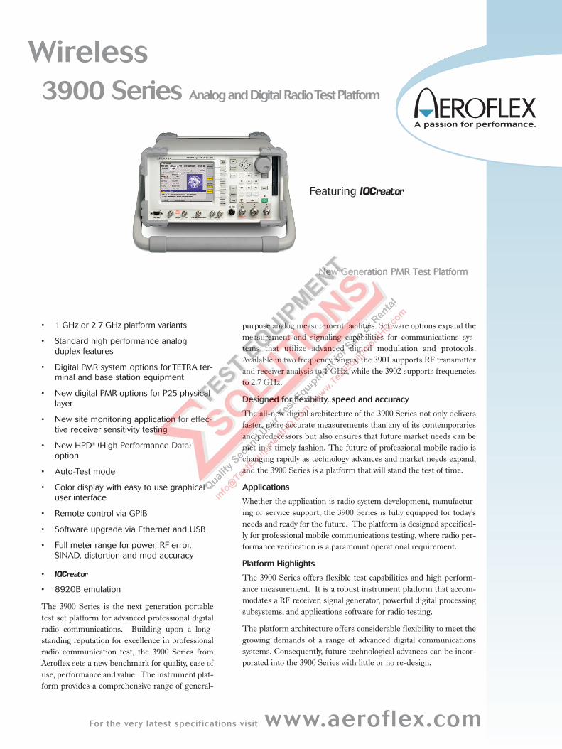
Wireless
3900 Series Analog and Digital Radio TestPlatform
• 1 GHz or 2.7 GHz platform variants
• Standard high performance analog
duplex features
• Digital PMR system options for TETRA ter-
minal and base station equipment
• New digital PMR options for P25 physical
layer
• New site monitoring application for effec-
tive receiver sensitivity testing
• New HPD® (High Performance Data)
option
• Auto-Test mode
• Color display with easy to use graphical
user interface
• Remote control via GPIB
• Software upgrade via Ethernet and USB
• Full meter range for power, RF error,
SINAD, distortion and mod accuracy
•
• 8920B emulation
The 3900 Series is the next generation portabletest set platform for advanced professional digitalradio communications. Building upon a long-standing reputation for excellence in professionalradio communication test, the 3900 Series fromAeroflex sets a new benchmark for quality, ease ofuse, performance and value. The instrument plat-form provides a comprehensive range of general-
purpose analog measurement facilities. Software options expand themeasurement and signaling capabilities for communications sys-tems that utilize advanced digital modulation and protocols.Available in two frequency ranges, the 3901 supports RF transmitterand receiver analysis to 1 GHz, while the 3902 supports frequenciesto 2.7 GHz.
Designed for flexibility, speed and accuracy
The all-new digital architecture of the 3900 Series not only deliversfaster, more accurate measurements than any of its contemporariesand predecessors but also ensures that future market needs can bemet in a timely fashion. The future of professional mobile radio ischanging rapidly as technology advances and market needs expand,and the 3900 Series is a platform that will stand the test of time.
Applications
Whether the application is radio system development, manufactur-ing or service support, the 3900 Series is fully equipped for today'sneeds and ready for the future. The platform is designed specifical-ly for professional mobile communications testing, where radio per-formance verification is a paramount operational requirement.
Platform Highlights
The 3900 Series offers flexible test capabilities and high perform-ance measurement. It is a robust instrument platform that accom-modates a RF receiver, signal generator, powerful digital processingsubsystems, and applications software for radio testing.
The platform architecture offers considerable flexibility to meet thegrowing demands of a range of advanced digital communicationssystems. Consequently, future technological advances can be incor-porated into the 3900 Series with little or no re-design.
Featuring
More importantly, through the use of software re-configurable digitalarchitecture, future technologies and enhancements can be achievedwith simple field programmable software updates. Whatever the sys-tem-specific needs of modulation, protocols, applications-specificsignal processing, special instrument features, and custom softwareapplications - all can be reconfigured in software. This establishesthe platform as a dependable long-term investment.
Combined with the power of an onboard PC with a 30 GB hard-driveand Linux OS, the 3900 Series also supports mouse and keyboardinterface as well as almost unlimited save/recall setups, saving timeand effort.
Performance Highlights:
Wide Frequency Range: The 3900 Series includes two variants.The 3901 provides continuous frequency coverage from 1 MHz to 1GHz while the 3902 extends the maximum frequency to 2.7 GHz.
Broadband RF Power: Direct input of signal power of up to 125 Wis supported, making the 3900 Series compatible with virtually allpractical requirements for mobile terminal and base station test.
Inband Low Level RF Power Measurements: For sensitivemeasurement, e.g. off-air analysis, a low power input is provided viathe antenna input port. This low level input gives the user the abili-ty to measure an off the air signal as low as -100 dBm or -115 dBmwith the internal per-amp selected.
High Stability Time Base: With a 0.01 ppm OCXO frequency stan-dard, the 3900 series provides ultra-reliable RF frequency measure-ments.
0.6 dB Accurate (Typical) RF Generators: Level accuracy isimportant in determining today's receiver performance in design,manufacturing and field service environments.
With a 1 dB (0.6 dB typical) level accuracy on the RF output ports, the3900 Series provides consistent results in testing receiver parameters.
Full Span Spectrum Analyzer: View signals from 1 MHz to 1 GHzwith the 3901 or to a full 2.7 GHz with the 3902. This full band ana-lyzer provides plenty of range to view harmonics and other spuriousemmissions in and out of band.
Wide Band Channel Analyzer: The channel analyzer makes itpossible to monitor a 5 MHz spectral window around the carrier whilesimultaneously demodulating the signal. This allows the spectrumaround the carrier to be analyzed while the device under test is par-ticipating in a call.
Dual-Channel 4 MHz Oscilloscope: High performance baseband analysis of audio and digital signals can be performed easily andaccurately.
High Performance Audio Features: With high accuracy audiogenerators from 1 mV to 5 V rms, the 3900 Series provides level accu-racy to ± 1% of the setting. The audio generator frequency rangesfrom 20 Hz to 40 kHz with 50 ppm accuracy (10 ppm typical) and0.1 Hz resolution provides solid audio performance for audio testing.The AF Counter features full range from 20 Hz to 20 kHz .
Speed: Measurement speed is directly related to processing powerand internal communications. The 3900 Series digital architectureutilizes a mixture of powerful digital signal processors and program-mable logic. Coupled to the use of a compact PCI backplane capable
of delivering peak rates of >100 Mbytes/s, this ensures that theinstrument has the power to acquire, synchronize and process data,producing measurement results to the user with the minimum ofdelay.
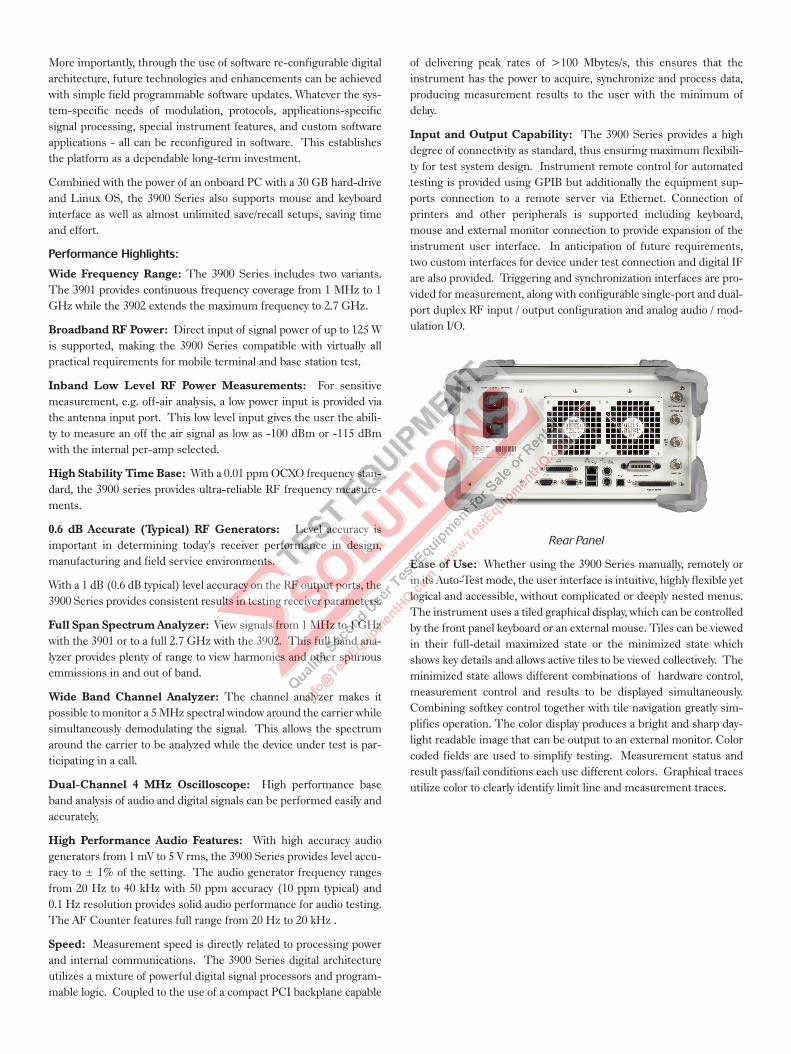
Input and Output Capability: The 3900 Series provides a highdegree of connectivity as standard, thus ensuring maximum flexibili-ty for test system design. Instrument remote control for automatedtesting is provided using GPIB but additionally the equipment sup-ports connection to a remote server via Ethernet. Connection ofprinters and other peripherals is supported including keyboard,mouse and external monitor connection to provide expansion of theinstrument user interface. In anticipation of future requirements,two custom interfaces for device under test connection and digital IFare also provided. Triggering and synchronization interfaces are pro-vided for measurement, along with configurable single-port and dual-port duplex RF input / output configuration and analog audio / mod-ulation I/O.
Rear Panel
Ease of Use: Whether using the 3900 Series manually, remotely orin its Auto-Test mode, the user interface is intuitive, highly flexible yetlogical and accessible, without complicated or deeply nested menus.The instrument uses a tiled graphical display, which can be controlledby the front panel keyboard or an external mouse. Tiles can be viewedin their full-detail maximized state or the minimized state whichshows key details and allows active tiles to be viewed collectively. Theminimized state allows different combinations of hardware control,measurement control and results to be displayed simultaneously.Combining softkey control together with tile navigation greatly sim-plifies operation. The color display produces a bright and sharp day-light readable image that can be output to an external monitor. Colorcoded fields are used to simplify testing. Measurement status andresult pass/fail conditions each use different colors. Graphical tracesutilize color to clearly identify limit line and measurement traces.
For the very latest specifications visit www.aeroflex.com
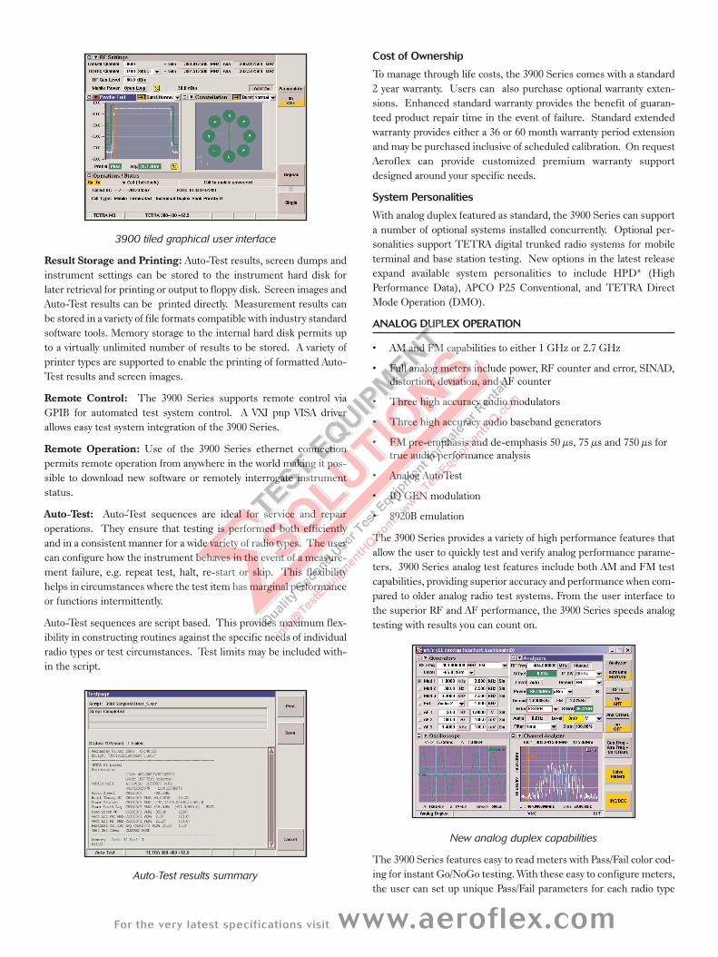
3900 tiled graphical user interface
Result Storage and Printing: Auto-Test results, screen dumps andinstrument settings can be stored to the instrument hard disk forlater retrieval for printing or output to floppy disk. Screen images andAuto-Test results can be printed directly. Measurement results canbe stored in a variety of file formats compatible with industry standardsoftware tools. Memory storage to the internal hard disk permits upto a virtually unlimited number of results to be stored. A variety ofprinter types are supported to enable the printing of formatted Auto-Test results and screen images.
Remote Control: The 3900 Series supports remote control viaGPIB for automated test system control. A VXI pnp VISA driverallows easy test system integration of the 3900 Series.
Remote Operation: Use of the 3900 Series ethernet connectionpermits remote operation from anywhere in the world making it pos-sible to download new software or remotely interrogate instrumentstatus.
Auto-Test: Auto-Test sequences are ideal for service and repairoperations. They ensure that testing is performed both efficientlyand in a consistent manner for a wide variety of radio types. The usercan configure how the instrument behaves in the event of a measure-ment failure, e.g. repeat test, halt, re-start or skip. This flexibilityhelps in circumstances where the test item has marginal performanceor functions intermittently.
Auto-Test sequences are script based. This provides maximum flex-ibility in constructing routines against the specific needs of individualradio types or test circumstances. Test limits may be included with-in the script.
Auto-Test results summary
Cost of Ownership
To manage through life costs, the 3900 Series comes with a standard2 year warranty. Users can also purchase optional warranty exten-sions. Enhanced standard warranty provides the benefit of guaran-teed product repair time in the event of failure. Standard extendedwarranty provides either a 36 or 60 month warranty period extensionand may be purchased inclusive of scheduled calibration. On requestAeroflex can provide customized premium warranty supportdesigned around your specific needs.
System Personalities
With analog duplex featured as standard, the 3900 Series can supporta number of optional systems installed concurrently. Optional per-sonalities support TETRA digital trunked radio systems for mobileterminal and base station testing. New options in the latest releaseexpand available system personalities to include HPD® (HighPerformance Data), APCO P25 Conventional, and TETRA DirectMode Operation (DMO).
ANALOG DUPLEX OPERATION
• AM and FM capabilities to either 1 GHz or 2.7 GHz
• Full analog meters include power, RF counter and error, SINAD,distortion, deviation, and AF counter
• Three high accuracy audio modulators
• Three high accuracy audio baseband generators
• FM pre-emphasis and de-emphasis 50 µs, 75 µs and 750 µs fortrue audio performance analysis
• Analog AutoTest
• IQ GEN modulation
• 8920B emulation
The 3900 Series provides a variety of high performance features thatallow the user to quickly test and verify analog performance parame-ters. 3900 Series analog test features include both AM and FM testcapabilities, providing superior accuracy and performance when com-pared to older analog radio test systems. From the user interface tothe superior RF and AF performance, the 3900 Series speeds analogtesting with results you can count on.
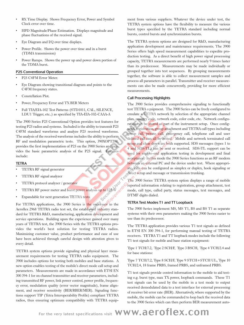
New analog duplex capabilities
The 3900 Series features easy to read meters with Pass/Fail color cod-ing for instant Go/NoGo testing. With these easy to configure meters,the user can set up unique Pass/Fail parameters for each radio type

that is being tested. When used with the save/recall locations, thisallows for instant recall of the test parameters so semi-technical ornon-technical individuals can simply key the radio and test. Themeters will display "Green" for good, "Red" for high and "Blue" for low.A quick glance and the operator will know that the radio is withinestablished test parameters.
The AutoTest Analog option provides the ability for users to create,save and run automated test scripts for conventional FM and AMradio systems. The 3900 Series has the ability, via a USB to RS-232converter, to issue command strings to a device to automate testing.
IQ Gen Modulation
A new option for the 3900 is the ability to upload waveforms createdfor the 3900 by . is an Aeroflex developed PCbased software utility that gives the user the ability to develop theirown waveforms to use as the modulation source. Since the waveformsare defined by I and Q, virtually any type of complex digital modula-tion format can be created. Once the IQ waveform is created it caneasily be uploaded to the 3900 and used as the modulation source inthe Analog Duplex System.
8920B Emulation
The 3900 now has the ability to replace your worn out 8920B.Enhancements have been implemented that enable the 3900 to emu-late most of the 8920B's remote operation via GPIB. These enhance-ments include the ability to perform measurements and setups in away that equals or surpasses the capability and speed of the 8920B. Inaddition, most of the 8920B functionality is available from the frontpanel of the 3900, with an easy to use, mouse driven, user interface.
Audio Testing
Subjective audio testing is supported for simplex and duplex calls.Audio spoken into the mobile's microphone is received and stored bythe test set, which then re-transmits the speech so that it is replayedthrough the mobile's speaker or ear piece with 2 seconds delay added,thus providing an end to end audio quality test. It is also possible tomonitor the terminal audio output during silence or tone stimulation.This allows investigation of audio pickup or noise type problems.
Site Monitoring
With a new level of automation that was previously unattainable withpast radio test systems, the 3900 Series brings impressive new capa-bilities to site monitoring applications. With the ability to leave the3900 on site, the 3900 Series provides automated data logging of thesite's effective receiver sensitivity. When connected to a good docu-mented receiver (a "golden" radio), the 3900 Series will automaticallycalculate the Effective Receiver Sensitivity (ERS) at a predeterminedinterval (example: every 10 seconds) over a specified time (example:log ERS for 72 hours). As these measurements are taken, a min/aver-age/max SINAD is displayed and the data is logged to the 3900's inter-nal hard-drive. Spectral information is also optionally logged witheach measurement to help locate and track sources of interference.This gives the system engineer a valuable tool in determining sitelocation performance and system RF boundaries. The 3900 Seriesprovides the user with the ability to recall the ERS point at givenintervals, as well as spectral data at each of the sample points to viewinterferers that may be present at one particular time, but not anoth-er (for example - 2AM).
HPD® OPERATION
• Generate/Receive HPD Signals
• Modulation - 64QAM, 16QAM and QPSK
• Transmitter Parameters including Signal Power, FrequencyError, EVM,
• Symbol Clock Error, RX BER, Burst Timing Error andOccupied Bandwidth.
• I & Q Modulation Analysis including constellation and trajectoryplots of the data symbols, synch and pilot bits.
• Display of Min/Max and Average as specified by the number ofbursts.
• Pass/Fail Indication using Color Codes Meters.
This test mode has been developed by Aeroflex for Motorola toaddress the need for testing their High Performance packet Dataoperation on both mobiles and base stations in the 700 and 800 MHzbands. HPD® systems operate within the normal 25 kHz mobile radiobandwidth.
The 3900 HPD® options 390XOPT300 and 390XOPT301 provideusers with the ability to test High Performance Data systems.
HPD® can be configured for two modes of operation. When config-ured to operate in BR Mode the Test Set simulates Base Radio oper-ation and is used to test the functionality of Motorola HPD® MSU's.When configured to operate in MSU Mode the Test Set simulatesMobile Subscriber Unit operation and is used to test the functionali-ty of Motorola BR's.
More advanced test features are available with 390XOPT301 includ-ing:
• Received Data Stream Logger. Logs the data portion of theHPD signal and displays it in hex.
For the very latest specifications visit www.aeroflex.com
• RX Time Display. Shows Frequency Error, Power and SymbolClock error over time.
• HPD Magnitude/Phase Estimation. Displays magnitude andphase fluctuations of the received signal.
• Eye Diagram and I/Q over time displays.
• Power Profile. Shows the power over time and in a burst(TDMA transmission)
• Power Ramps. Shows the power up and power down portion ofthe TDMA burst.
P25 Conventional Operation
• P25 C4FM Error Meter.
• Eye Diagram showing transitional diagram and points to theC4FM frequency states.
• Constellation Plot.
• Power, Frequency Error and TX BER Meters
• Full TIA/EIA-102 Test Patterns (STD1011, CAL, SILENCE,LDU1 Trigger, etc..) as specified by TIA-EIA-102-CAAA-A
The 3900 Series P25 Conventional Option provides test features fortesting P25 radios and systems. Included is the ability to transmit P25C4FM standard waveforms and analyze P25 received waveforms.The analysis of the received waveforms includes the ability to performRF and modulation parametric tests. This option, 390XOPT200,provides the first implementation of P25 on the 3900 Series and pro-vides the basic parametric analysis of the P25 signal. Featuresinclude:
TETRA
• TETRA RF signal generator
• TETRA RF signal analyzer
• TETRA protocol analyzer / generator
• TETRA RF power meter and burst power analysis up to 125 W
• Expandable for next generation TETRA tests
For TETRA applications, the 3900 Series is the successor to theAeroflex 2968 TETRA radio test set, the established industry stan-dard for TETRA R&D, manufacturing, application development andservice operations. Building upon the experience gained over manyyears of TETRA test, the 3900 Series with the TETRA options pro-vides the world's best solution for testing TETRA radios.Maximizing customer value, product performance and ease of usehave been achieved through careful design with attention given toevery detail.
TETRA system options provide signaling and physical layer meas-urement requirements for testing TETRA radio equipment. The3900 includes options for testing both mobiles and base stations. Anew option enables testing of the mobile's direct mode call setup andparameters. Measurements are made in accordance with ETSI EN300 394-1 for on channel transmitter and receiver parameters, includ-ing transmitted RF power, link power control, power profile, frequen-cy error, modulation quality (error vector magnitude), frame align-ment, and receiver sensitivity (BER/RBER/MER). Signaling func-tions support TIP (Tetra Interoperability Profile) compliant TETRAradios, thus ensuring optimum compatibility with TETRA equip-
ment from various suppliers. Whatever the device under test, theTETRA system options have the flexibility to measure the variousburst types specified by the TETRA standard including normalbursts, control bursts and synchronization bursts.
The TETRA system options are designed for R&D, manufacturingapplication development and maintenance requirements. The 3900Series offers high speed measurement capabilities to expedite pro-duction testing. As a direct benefit of high power signal processingcapacity, TETRA measurements are performed nearly 9 times fasterthan its predecessor. Measurements may be made individually orgrouped together into test sequences. By grouping measurementstogether, the software is able to collect measurement samples andprocess all parameters in parallel. Transmitter and receiver measure-ments can also be made concurrently, providing for more efficientmeasurements.
Call Processing Highlights
The 3900 Series provides comprehensive signaling to functionallytest TETRA equipment. The 3900 Series can be freely configured toemulate a TETRA network by selection of the appropriate channelplan, country code, network code, color code, etc. Network configu-ration can be stored as part of the instrument setup. Once config-ured, registration, group attachment and TETRA call types includinggroup call, private call, emergency call, telephone call and userdefined call can all be tested. Mobile and network terminated callsetup and clear down are both supported. SDS messages (types 1 to4 and SDS-TL) can be sent or received. SDS-TL support can beused for end-to-end application testing in development and finalacceptance. In this mode the 3900 Series functions as an RF modembetween an external PC and the device under test. Where appropri-ate, calls can be configured as simplex or duplex, hook signaling ordirect setup and message or transmission trunking.
The 3900 Series TETRA system option displays a range of mobilereported information relating to registration, group attachment, testmode, call type, called party, status messages, text messages, andDTMF digits dialed.
TETRA Test Modes T1 and TT Loopback
The 3900 Series implement MS, MS T1, BS and BS T1 as separatesystems with their own parameters making the 3900 Series easier touse than its predecessor.
The TETRA application provides various T1 test signals as definedin ETSI EN 300 394-1, for performing manual testing of TETRAreceivers. TETRA T1 and TT loopback modes include the followingT1 test signals for mobile and base station equipment:
Type 1 TCH/7.2, Type 2 SCH/F, Type 3 BSCH, Type 4 TCH/2.4 andfor base stations:
Type 7 TCH/7.2, Type 8 SCH/F, Type 9 STCH+STCH UL, Type 10TCH/2.4, 18 frame PRBS, framed PRBS, and unframed PRBS.
T1 test signals provide control information to the mobile to aid test-ing e.g. burst type, max TX power, loopback commands. These T1test signals can be used by the mobile in a test mode to outputreceived demodulated data to a test interface for external processingof receiver bit error rate (BER). Alternatively, where supported by themobile, the mobile can be commanded to loop back the received datato the 3900 Series which can then perform BER measurement auto-
matically where the application software will recover the modulateddata and perform automated BER measurement. In this "T1 loop-back mode", the BER is reported for a user specified number of bitsamples. When supported by the terminal type, the application alsosupports TT loopback mode whereby the receiver's BER, MER andRBER performance can all be reported. The 3900 Series TETRAoption 111 also supports T1 loopback BER / MER / PUEM measure-ments for base stations.
Results
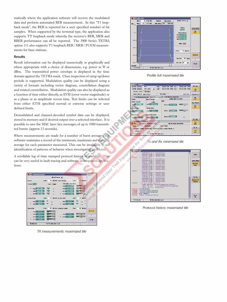
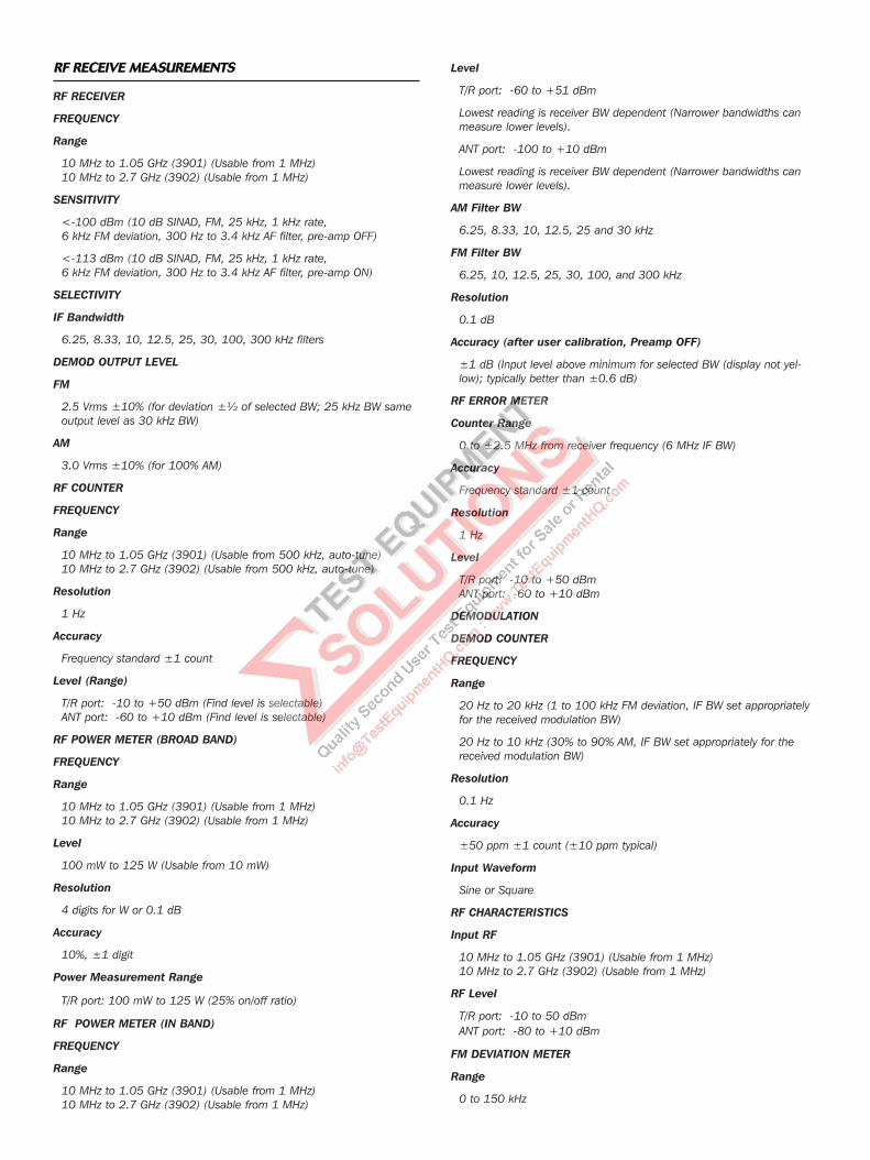
Result information can be displayed numerically or graphically andwhere appropriate with a choice of dimensions, e.g. power in W ordBm. The transmitted power envelope is displayed in the timedomain against the TETRA mask. Close inspection of ramp up/downperiods is supported. Modulation quality can be displayed using avariety of formats including vector diagram, constellation diagramand rotated constellation. Modulation quality can also be displayed asa function of time either directly, as EVM (error vector magnitude) oras a phase or as amplitude versus time. Test limits can be selectedfrom either ETSI specified normal or extreme settings or userdefined limits.
Demodulated and channel-decoded symbol data can be displayed,stored to memory and if desired output over a selected interface. It ispossible to save the MAC layer hex messages of up to 1000 transmit-ted bursts (approx 13 seconds).
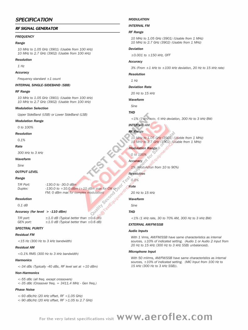
Where measurements are made for a number of burst averages, thesoftware maintains a record of the minimum, maximum and runningaverage for each parameter measured. This can be invaluable to aididentification of patterns of behavior when investigating problems.
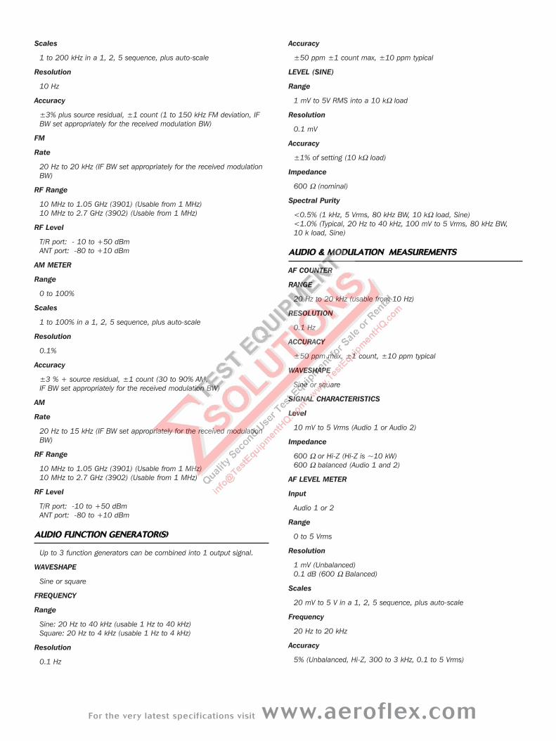
A scrollable log of time stamped protocol history is available. Thiscan be very useful in fault tracing and software development applica-tions.
TX measurements maximized tile
Profile full maximized tile
Tx and Rx minimized tile
Protocol history maximized tile
For the very latest specifications visit www.aeroflex.com
SSPPEECCIIFFIICCAATTIIOONN
RRFF SSIIGGNNAALL GGEENNEERRAATTOORR
FREQUENCY
Range
10 MHz to 1.05 GHz (3901) (Usable from 100 kHz)10 MHz to 2.7 GHz (3902) (Usable from 100 kHz)
Resolution
1 Hz
Accuracy
Frequency standard ±1 count
INTERNAL SINGLE-SIDEBAND (SBB)
RF Range
10 MHz to 1.05 GHz (3901) (Usable from 100 kHz)10 MHz to 2.7 GHz (3902) (Usable from 100 kHz)
Modulation Selection
Upper SideBand (USB) or Lower SideBand (LSB)
Modulation Range
0 to 100%
Resolution
0.1%
Rate
300 kHz to 3 kHz
Waveform
Sine
OUTPUT LEVEL
Range
T/R Port: -130.0 to -30.0 dBmDuplex: -130.0 to +10.0 dBm (+10 dBm max for CW or
FM; 0 dBm max for complex modulation)
Resolution
0.1 dB
Accuracy (for level > -110 dBm)
T/R port: ±1.0 dB (Typical better than ±0.6 dB)GEN port: ±1.0 dB (Typical better than ±0.6 dB)
SPECTRAL PURITY
Residual FM
<15 Hz (300 Hz to 3 kHz bandwidth)
Residual AM
<0.1% RMS (300 Hz to 3 kHz bandwidth)
Harmonics
<-34 dBc (Typically -40 dBc, RF level set at +10 dBm)
Non-Harmonics
<-55 dBc (all freq. except crossovers)<-35 dBc (Crossover freq. = 3411.4 MHz - Gen freq.)
Phase Noise
<-93 dBc/Hz (20 kHz offset, RF <1.05 GHz)<-90 dBc/Hz (20 kHz offset, RF >1.05 to 2.7 GHz)
MODULATION
INTERNAL FM
RF Range
10 MHz to 1.05 GHz (3901) (Usable from 1 MHz)10 MHz to 2.7 GHz (3902) (Usable from 1 MHz)
Deviation
±0.001 to ±150 kHz, OFF
Accuracy
3% (From ±1 kHz to ±100 kHz deviation, 20 Hz to 15 kHz rate)
Resolution
1 Hz
Deviation Rate
20 Hz to 15 kHz
Waveform
Sine
THD
<1% (1 kHz rate, 6 kHz deviation, 300 Hz to 3 kHz BW)
INTERNAL AM
RF Range
10 MHz to 1.05 GHz (3901) (Usable from 1 MHz)10 MHz to 2.7 GHz (3902) (Usable from 1 MHz)
Modulation Range
0 to 100%
Accuracy
1% (Modulation from 10 to 90%)
Resolution
0.1%
Rate
20 Hz to 15 kHz
Waveform
Sine
THD
<1% (1 kHz rate, 30 to 70% AM, 300 Hz to 3 kHz BW)
EXTERNAL AM/FM/SSB
Audio Inputs
With 1 Vrms, AM/FM/SSB have same characteristics as internalsources, ±10% of indicated setting. (Audio 1 or Audio 2 input from20 Hz to 15 kHz (300 Hz to 3 kHz SSB) unbalanced).
Microphone Input
With 50 mVrms, AM/FM/SSB have same characteristics as internalsources, ±10% of indicated setting. (MIC Input from 100 Hz to 15 kHz (300 Hz to 3 kHz SSB)).
RRFF RREECCEEIIVVEE MMEEAASSUURREEMMEENNTTSS
RF RECEIVER
FREQUENCY
Range
10 MHz to 1.05 GHz (3901) (Usable from 1 MHz)10 MHz to 2.7 GHz (3902) (Usable from 1 MHz)
SENSITIVITY
<-100 dBm (10 dB SINAD, FM, 25 kHz, 1 kHz rate, 6 kHz FM deviation, 300 Hz to 3.4 kHz AF filter, pre-amp OFF)
<-113 dBm (10 dB SINAD, FM, 25 kHz, 1 kHz rate, 6 kHz FM deviation, 300 Hz to 3.4 kHz AF filter, pre-amp ON)
SELECTIVITY
IF Bandwidth
6.25, 8.33, 10, 12.5, 25, 30, 100, 300 kHz filters
DEMOD OUTPUT LEVEL
FM
2.5 Vrms ±10% (for deviation ±½ of selected BW; 25 kHz BW sameoutput level as 30 kHz BW)
AM
3.0 Vrms ±10% (for 100% AM)
RF COUNTER
FREQUENCY
Range
10 MHz to 1.05 GHz (3901) (Usable from 500 kHz, auto-tune)10 MHz to 2.7 GHz (3902) (Usable from 500 kHz, auto-tune)
Resolution
1 Hz
Accuracy
Frequency standard ±1 count
Level (Range)
T/R port: -10 to +50 dBm (Find level is selectable)ANT port: -60 to +10 dBm (Find level is selectable)
RF POWER METER (BROAD BAND)
FREQUENCY
Range
10 MHz to 1.05 GHz (3901) (Usable from 1 MHz)10 MHz to 2.7 GHz (3902) (Usable from 1 MHz)
Level
100 mW to 125 W (Usable from 10 mW)
Resolution
4 digits for W or 0.1 dB
Accuracy
10%, ±1 digit
Power Measurement Range
T/R port: 100 mW to 125 W (25% on/off ratio)
RF POWER METER (IN BAND)
FREQUENCY
Range
10 MHz to 1.05 GHz (3901) (Usable from 1 MHz)10 MHz to 2.7 GHz (3902) (Usable from 1 MHz)
Level
T/R port: -60 to +51 dBm
Lowest reading is receiver BW dependent (Narrower bandwidths canmeasure lower levels).
ANT port: -100 to +10 dBm
Lowest reading is receiver BW dependent (Narrower bandwidths canmeasure lower levels).
AM Filter BW
6.25, 8.33, 10, 12.5, 25 and 30 kHz
FM Filter BW
6.25, 10, 12.5, 25, 30, 100, and 300 kHz
Resolution
0.1 dB
Accuracy (after user calibration, Preamp OFF)
±1 dB (Input level above minimum for selected BW (display not yel-low); typically better than ±0.6 dB)
RF ERROR METER
Counter Range
0 to ±2.5 MHz from receiver frequency (6 MHz IF BW)
Accuracy
Frequency standard ±1 count
Resolution
1 Hz
Level
T/R port: -10 to +50 dBmANT port: -60 to +10 dBm
DEMODULATION
DEMOD COUNTER
FREQUENCY
Range
20 Hz to 20 kHz (1 to 100 kHz FM deviation, IF BW set appropriatelyfor the received modulation BW)
20 Hz to 10 kHz (30% to 90% AM, IF BW set appropriately for thereceived modulation BW)
Resolution
0.1 Hz
Accuracy
±50 ppm ±1 count (±10 ppm typical)
Input Waveform
Sine or Square
RF CHARACTERISTICS
Input RF
10 MHz to 1.05 GHz (3901) (Usable from 1 MHz)10 MHz to 2.7 GHz (3902) (Usable from 1 MHz)
RF Level
T/R port: -10 to 50 dBmANT port: -80 to +10 dBm
FM DEVIATION METER
Range
0 to 150 kHz
For the very latest specifications visit www.aeroflex.com
Scales
1 to 200 kHz in a 1, 2, 5 sequence, plus auto-scale
Resolution
10 Hz
Accuracy
±3% plus source residual, ±1 count (1 to 150 kHz FM deviation, IFBW set appropriately for the received modulation BW)
FM
Rate
20 Hz to 20 kHz (IF BW set appropriately for the received modulationBW)
RF Range
10 MHz to 1.05 GHz (3901) (Usable from 1 MHz)10 MHz to 2.7 GHz (3902) (Usable from 1 MHz)
RF Level
T/R port: - 10 to +50 dBmANT port: -80 to +10 dBm
AM METER
Range
0 to 100%
Scales
1 to 100% in a 1, 2, 5 sequence, plus auto-scale
Resolution
0.1%
Accuracy
±3 % + source residual, ±1 count (30 to 90% AM, IF BW set appropriately for the received modulation BW)
AM
Rate
20 Hz to 15 kHz (IF BW set appropriately for the received modulationBW)
RF Range
10 MHz to 1.05 GHz (3901) (Usable from 1 MHz)10 MHz to 2.7 GHz (3902) (Usable from 1 MHz)
RF Level
T/R port: -10 to +50 dBmANT port: -80 to +10 dBm
AAUUDDIIOO FFUUNNCCTTIIOONN GGEENNEERRAATTOORR((SS))
Up to 3 function generators can be combined into 1 output signal.
WAVESHAPE
Sine or square
FREQUENCY
Range
Sine: 20 Hz to 40 kHz (usable 1 Hz to 40 kHz)Square: 20 Hz to 4 kHz (usable 1 Hz to 4 kHz)
Resolution
0.1 Hz
Accuracy
±50 ppm ±1 count max, ±10 ppm typical
LEVEL (SINE)
Range
1 mV to 5V RMS into a 10 kΩ load
Resolution
0.1 mV
Accuracy
±1% of setting (10 kΩ load)
Impedance
600 Ω (nominal)
Spectral Purity
<0.5% (1 kHz, 5 Vrms, 80 kHz BW, 10 kΩ load, Sine)<1.0% (Typical, 20 Hz to 40 kHz, 100 mV to 5 Vrms, 80 kHz BW, 10 k load, Sine)
AAUUDDIIOO && MMOODDUULLAATTIIOONN MMEEAASSUURREEMMEENNTTSS
AF COUNTER
RANGE
20 Hz to 20 kHz (usable from 10 Hz)
RESOLUTION
0.1 Hz
ACCURACY
±50 ppm max, ±1 count, ±10 ppm typical
WAVESHAPE
Sine or square
SIGNAL CHARACTERISTICS
Level
10 mV to 5 Vrms (Audio 1 or Audio 2)
Impedance
600 Ω or Hi-Z (Hi-Z is ~10 kW)600 Ω balanced (Audio 1 and 2)
AF LEVEL METER
Input
Audio 1 or 2
Range
0 to 5 Vrms
Resolution
1 mV (Unbalanced)0.1 dB (600 Ω Balanced)
Scales
20 mV to 5 V in a 1, 2, 5 sequence, plus auto-scale
Frequency
20 Hz to 20 kHz
Accuracy
5% (Unbalanced, Hi-Z, 300 to 3 kHz, 0.1 to 5 Vrms)
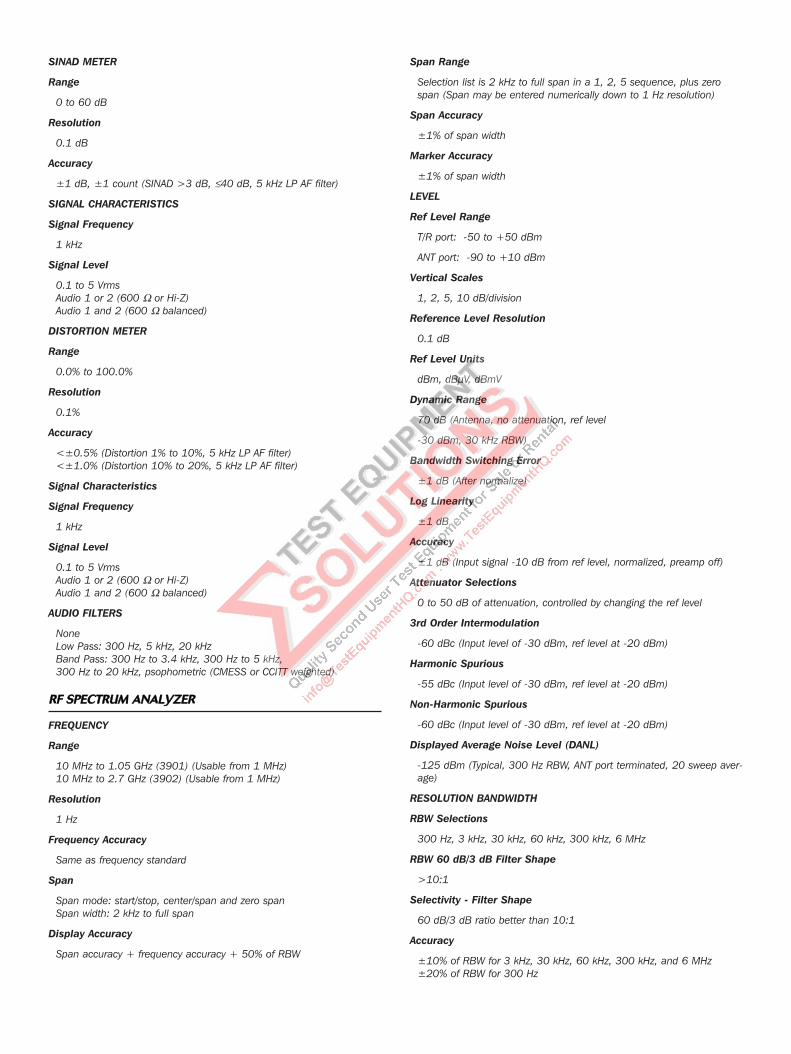
SINAD METER
Range
0 to 60 dB
Resolution
0.1 dB
Accuracy
±1 dB, ±1 count (SINAD >3 dB, ≤40 dB, 5 kHz LP AF filter)
SIGNAL CHARACTERISTICS
Signal Frequency
1 kHz
Signal Level
0.1 to 5 Vrms Audio 1 or 2 (600 Ω or Hi-Z)Audio 1 and 2 (600 Ω balanced)
DISTORTION METER
Range
0.0% to 100.0%
Resolution
0.1%
Accuracy
<±0.5% (Distortion 1% to 10%, 5 kHz LP AF filter)<±1.0% (Distortion 10% to 20%, 5 kHz LP AF filter)
Signal Characteristics
Signal Frequency
1 kHz
Signal Level
0.1 to 5 Vrms Audio 1 or 2 (600 Ω or Hi-Z)Audio 1 and 2 (600 Ω balanced)
AUDIO FILTERS
NoneLow Pass: 300 Hz, 5 kHz, 20 kHzBand Pass: 300 Hz to 3.4 kHz, 300 Hz to 5 kHz, 300 Hz to 20 kHz, psophometric (CMESS or CCITT weighted)
RRFF SSPPEECCTTRRUUMM AANNAALLYYZZEERR
FREQUENCY
Range
10 MHz to 1.05 GHz (3901) (Usable from 1 MHz)10 MHz to 2.7 GHz (3902) (Usable from 1 MHz)
Resolution
1 Hz
Frequency Accuracy
Same as frequency standard
Span
Span mode: start/stop, center/span and zero spanSpan width: 2 kHz to full span
Display Accuracy
Span accuracy + frequency accuracy + 50% of RBW
Span Range
Selection list is 2 kHz to full span in a 1, 2, 5 sequence, plus zerospan (Span may be entered numerically down to 1 Hz resolution)
Span Accuracy
±1% of span width
Marker Accuracy
±1% of span width
LEVEL
Ref Level Range
T/R port: -50 to +50 dBm
ANT port: -90 to +10 dBm
Vertical Scales
1, 2, 5, 10 dB/division
Reference Level Resolution
0.1 dB
Ref Level Units
dBm, dBµV, dBmV
Dynamic Range
70 dB (Antenna, no attenuation, ref level
-30 dBm, 30 kHz RBW)
Bandwidth Switching Error
±1 dB (After normalize)
Log Linearity
±1 dB
Accuracy
±1 dB (Input signal -10 dB from ref level, normalized, preamp off)
Attenuator Selections
0 to 50 dB of attenuation, controlled by changing the ref level
3rd Order Intermodulation
-60 dBc (Input level of -30 dBm, ref level at -20 dBm)
Harmonic Spurious
-55 dBc (Input level of -30 dBm, ref level at -20 dBm)
Non-Harmonic Spurious
-60 dBc (Input level of -30 dBm, ref level at -20 dBm)
Displayed Average Noise Level (DANL)
-125 dBm (Typical, 300 Hz RBW, ANT port terminated, 20 sweep aver-age)
RESOLUTION BANDWIDTH
RBW Selections
300 Hz, 3 kHz, 30 kHz, 60 kHz, 300 kHz, 6 MHz
RBW 60 dB/3 dB Filter Shape
>10:1
Selectivity - Filter Shape
60 dB/3 dB ratio better than 10:1
Accuracy
±10% of RBW for 3 kHz, 30 kHz, 60 kHz, 300 kHz, and 6 MHz±20% of RBW for 300 Hz
For the very latest specifications visit www.aeroflex.com
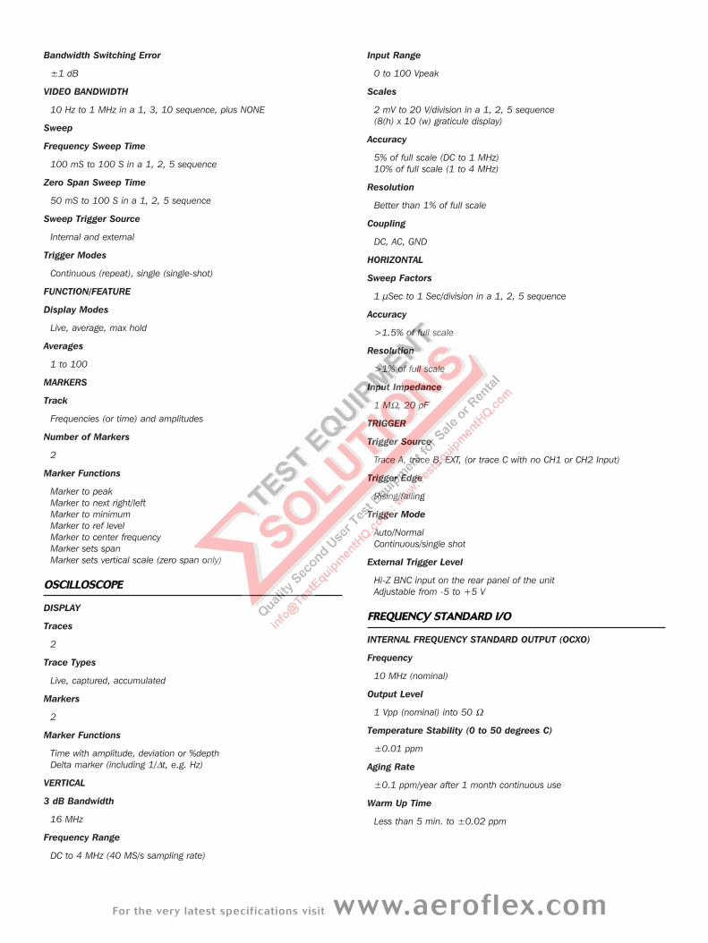
Bandwidth Switching Error
±1 dB
VIDEO BANDWIDTH
10 Hz to 1 MHz in a 1, 3, 10 sequence, plus NONE
Sweep
Frequency Sweep Time
100 mS to 100 S in a 1, 2, 5 sequence
Zero Span Sweep Time
50 mS to 100 S in a 1, 2, 5 sequence
Sweep Trigger Source
Internal and external
Trigger Modes
Continuous (repeat), single (single-shot)
FUNCTION/FEATURE
Display Modes
Live, average, max hold
Averages
1 to 100
MARKERS
Track
Frequencies (or time) and amplitudes
Number of Markers
2
Marker Functions
Marker to peakMarker to next right/leftMarker to minimumMarker to ref levelMarker to center frequencyMarker sets spanMarker sets vertical scale (zero span only)
OOSSCCIILLLLOOSSCCOOPPEE
DISPLAY
Traces
2
Trace Types
Live, captured, accumulated
Markers
2
Marker Functions
Time with amplitude, deviation or %depthDelta marker (including 1/∆t, e.g. Hz)
VERTICAL
3 dB Bandwidth
16 MHz
Frequency Range
DC to 4 MHz (40 MS/s sampling rate)
Input Range
0 to 100 Vpeak
Scales
2 mV to 20 V/division in a 1, 2, 5 sequence (8(h) x 10 (w) graticule display)
Accuracy
5% of full scale (DC to 1 MHz)10% of full scale (1 to 4 MHz)
Resolution
Better than 1% of full scale
Coupling
DC, AC, GND
HORIZONTAL
Sweep Factors
1 µSec to 1 Sec/division in a 1, 2, 5 sequence
Accuracy
>1.5% of full scale
Resolution
>1% of full scale
Input Impedance
1 MΩ, 20 pF
TRIGGER
Trigger Source
Trace A, trace B, EXT, (or trace C with no CH1 or CH2 Input)
Trigger Edge
Rising/falling
Trigger Mode
Auto/NormalContinuous/single shot
External Trigger Level
Hi-Z BNC input on the rear panel of the unitAdjustable from -5 to +5 V
FFRREEQQUUEENNCCYY SSTTAANNDDAARRDD II//OO
INTERNAL FREQUENCY STANDARD OUTPUT (OCXO)
Frequency
10 MHz (nominal)
Output Level
1 Vpp (nominal) into 50 Ω
Temperature Stability (0 to 50 degrees C)
±0.01 ppm
Aging Rate
±0.1 ppm/year after 1 month continuous use
Warm Up Time
Less than 5 min. to ±0.02 ppm
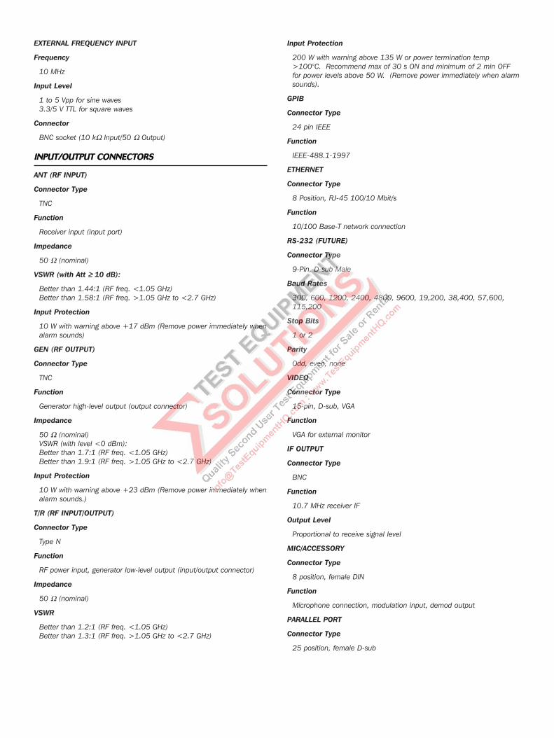
EXTERNAL FREQUENCY INPUT
Frequency
10 MHz
Input Level
1 to 5 Vpp for sine waves3.3/5 V TTL for square waves
Connector
BNC socket (10 kΩ Input/50 Ω Output)
IINNPPUUTT//OOUUTTPPUUTT CCOONNNNEECCTTOORRSS
ANT (RF INPUT)
Connector Type
TNC
Function
Receiver input (input port)
Impedance
50 Ω (nominal)
VSWR (with Att ≥≥ 10 dB):
Better than 1.44:1 (RF freq. <1.05 GHz)Better than 1.58:1 (RF freq. >1.05 GHz to <2.7 GHz)
Input Protection
10 W with warning above +17 dBm (Remove power immediately whenalarm sounds)
GEN (RF OUTPUT)
Connector Type
TNC
Function
Generator high-level output (output connector)
Impedance
50 Ω (nominal)VSWR (with level <0 dBm):Better than 1.7:1 (RF freq. <1.05 GHz)Better than 1.9:1 (RF freq. >1.05 GHz to <2.7 GHz)
Input Protection
10 W with warning above +23 dBm (Remove power immediately whenalarm sounds.)
T/R (RF INPUT/OUTPUT)
Connector Type
Type N
Function
RF power input, generator low-level output (input/output connector)
Impedance
50 Ω (nominal)
VSWR
Better than 1.2:1 (RF freq. <1.05 GHz)Better than 1.3:1 (RF freq. >1.05 GHz to <2.7 GHz)
Input Protection
200 W with warning above 135 W or power termination temp >100°C. Recommend max of 30 s ON and minimum of 2 min OFFfor power levels above 50 W. (Remove power immediately when alarmsounds).
GPIB
Connector Type
24 pin IEEE
Function
IEEE-488.1-1997
ETHERNET
Connector Type
8 Position, RJ-45 100/10 Mbit/s
Function
10/100 Base-T network connection
RS-232 (FUTURE)
Connector Type
9-Pin, D-sub Male
Baud Rates
300, 600, 1200, 2400, 4800, 9600, 19,200, 38,400, 57,600,115,200
Stop Bits
1 or 2
Parity
Odd, even, none
VIDEO
Connector Type
15-pin, D-sub, VGA
Function
VGA for external monitor
IF OUTPUT
Connector Type
BNC
Function
10.7 MHz receiver IF
Output Level
Proportional to receive signal level
MIC/ACCESSORY
Connector Type
8 position, female DIN
Function
Microphone connection, modulation input, demod output
PARALLEL PORT
Connector Type
25 position, female D-sub
For the very latest specifications visit www.aeroflex.com
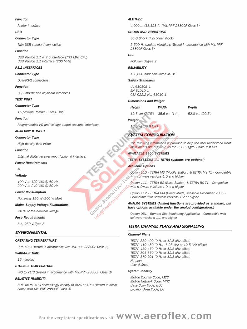
Function
Printer Interface
USB
Connector Type
Twin USB standard connection
Function
USB Version 1.1 & 2.0 interface (733 MHz CPU)USB Version 1.1 interface (266 MHz)
PS/2 INTERFACES
Connector Type
Dual-PS/2 connectors
Function
PS/2 mouse and keyboard interfaces
TEST PORT
Connector Type
15 position, female 3 tier D-sub
Function
Programmable I/O and voltage output (optional interface)
AUXILIARY IF INPUT
Connector Type
High-density dual-inline
Function
External digital receiver input (optional interface)
Power Requirements
AC
Voltage
100 V to 120 VAC @ 60 Hz220 V to 240 VAC @ 50 Hz
Power Consumption
Nominally 120 W (200 W Max)
Mains Supply Voltage Fluctuations
≤10% of the nominal voltage
Fuse Requirements
3 A, 250 V, Type F
EENNVVIIRROONNMMEENNTTAALL
OPERATING TEMPERATURE
0 to 50°C (Tested in accordance with MIL-PRF-28800F Class 3)
WARM-UP TIME
15 minutes
STORAGE TEMPERATURE
-40 to 71°C (Tested in accordance with MIL-PRF-28800F Class 3)
RELATIVE HUMIDITY
80% up to 31°C decreasingly linearly to 50% at 40°C (Tested in accor-dance with MIL-PRF-28800F Class 3)
ALTITUDE
4,000 m (13,123 ft) (MIL-PRF-28800F Class 3)
SHOCK AND VIBRATIONS
30 G Shock (functional shock)
5-500 Hz random vibrations (Tested in accordance with MIL-PRF-28800F Class 3)
USE
Pollution degree 2
RELIABILITY
> 8,000 hour calculated MTBF
Safety Standards
UL 61010B-1EN 61010-1CSA C22.2 No. 61010-1
Dimensions and Weight
Height Width Depth
19.7 cm (7.75") 35.6 cm (14") 52.0 cm (20.5")
Weight
16.5 kg (36.8 lbs.)
SSYYSSTTEEMM CCOONNFFIIGGUURRAATTIIOONN
The following information is provided to help the user understand whatinstruments are available on the 3900 Digital Radio Test Set.
AVAILABLE 3900 SYSTEMS
TETRA SYSTEMS (All TETRA systems are optional)
Available Options
Option 110 - TETRA MS (Mobile Station) & TETRA MS T1 - Compatiblewith software versions 1.0 and higher
Option 111 - TETRA BS (Base Station) & TETRA BS T1 - Compatiblewith software versions 1.0 and higher
Option 112 - TETRA DM (Direct Mode) Available December 2005 -Compatible with software versions 1.2 or higher
ANALOG SYSTEMS (Analog functions are provided as standard, buthave options available under the analog configuration.)
Option 051 - Remote Site Monitoring Application - Compatible withsoftware versions 1.1 and higher
TTEETTRRAA CCHHAANNNNEELL PPLLAANNSS AANNDD SSIIGGNNAALLLLIINNGG
Channel Plans
TETRA 380-400 (0 Hz or 12.5 kHz offset)TETRA 410-430 (0 Hz, -6.25 kHz or 12.5 kHz offset)TETRA 450-470 (0 Hz or 12.5 kHz offset)TETRA 805-870 (0 Hz or 12.5 kHz offset)TETRA 870-921 (0 Hz or 12.5 kHz offset)No planUser defined
System Identity
Mobile Country Code, MCCMobile Network Code, MNCBase Color Code, BCCLocation Area Code, LA
Test Modes
Manual test / Auto-Test MS (see Auto-Test)
Manual Test Signaling Functions (TETRA MS mode only)
Protocol functions are compatible with TIP compliant mobiles.Mobile parameter control for SSI, GSSI, power class, receiver classRegistration, test mode registration and de-registrationPrivate (individual) call, group call, phone call, emergency call, userdefined call (mobile terminated)Call timer and trunking type selectionCell-re-selection (requires two test sets and a power splitter)Short data serviceStatus message and SDS types 1 to 4call control (simplex calls)Power controlFrequency controlFrequency handoffRF loopback control (TT) Display of mobile informationDemodulated and channel decoded dataProtocol history displaySubjective mobile audio testsTalk back, silence and test tone (1 kHz digitally encoded)
TTEETTRRAA MMEEAASSUURREEMMEENNTTSS
TETRA RECEIVER MEASUREMENTS
TETRA MS T1 mode, TETRA MS mode, TETRA BS T1 mode
(T1 loopback, TT loopback BER, MER, PUEM, RBER, with pre-set /user defined limit checking, subjective audio testing, (TETRA MSmode), audio talk-back, test tone, silence)
BER Testing (TETRA MS T1 mode)
BER and MER
BER Testing (TETRA MS mode)
BER, RBER and MER
BER Testing (TETRA BS T1 mode)
BER, MER and PUEM
SINAD Meter
Same as platform specifications
TETRA TRANSMITTER MEASUREMENTS
RF power, RF power profile, burst timing, error vector magnitude, fre-quency error, residual carrier each with pre-set / user defined resultlimit checking
Input Range
T/R - 40 dBm to + 40 dBm Ant -80 dBm to 0 dBm
Burst Types
MS: Control Burst (CB), Normal Uplink Burst (NUB)BS: Synchronization Burst (SB), Normal Downlink Burst (NDB)
TETRA RF POWER METER
Average power across the useful part of the burst measured at thesymbol points through a TETRA filter. Results available for avg, maxand min for a sample of up to 250 bursts
Units
dBm / W
Resolution
0.1 dB / 1 mW
Indication
Numerical value, bar chart and progress indicator
Accuracy
±1.0 dB (±0.6 dB typical)
Level Offset Range
±40.0 dB
TETRA RF POWER PROFILE
(see graphical displays)
BURST TIMING ERROR (MS / MS T1 only)
Timing error relative to downlink
Results available for avg, max, min and worst case for a sample of upto 250 bursts
Range
±510.00 symbols
Indication
Numerical value, bar chart and progress indicator
Accuracy
±0.05 symbols
Timing offset range
±999.99 symbols
MODULATION ACCURACY
Modulation accuracy measures the displacement of symbol points fromtheir ideal position.
Results available for avg and max for a sample of up to 250 bursts
Modulation Error Range
20.0% RMS Vector error40.0% Peak Vector error20.0% Residual Carrier
Indication
Numerical value, bar chart and progress indicator
Accuracy
±0.5% at 10% error
FREQUENCY ERROR
Frequency error is the error relative to the expected frequency.
Results available for avg, max, min and worst case for a sample of upto 250 bursts
Frequency Error Range
±500.0 Hz
Indication
Numerical value, bar chart and progress indicator
Accuracy
±15 Hz + frequency standard accuracy
GGRRAAPPHHIICCAALL DDIISSPPLLAAYYSS
BAR CHARTS
Display of average, max, min and worst case values as appropriatewith progress bar. Bar chart is color coded to indicate pass, fail low,fail high or accumulating.
POWER PROFILE DISPLAY
Display of power versus time for a complete burst or ramp up/rampdown intervals measured at the symbol points and displayed relative toa TETRA mask (TETRA limits or user defined) with pass/fail indication.Measured through a TETRA filter referenced (0 dB) to average power.
For the very latest specifications visit www.aeroflex.com
Displayed profile and pass / fail indication are available as the averagefor a sample of up to 250 bursts. (N.B. multiple burst averaging isNOT available for the other graphical displays, only for the power pro-file).
Power Profile Dynamic Range
70 dB
Vertical Scale
20 dB/div or 0.1 dB/div in 1,2,5 steps
Accuracy
±1.0 dB (±0.6 dB typical) at symbol points for levels greater than -10 dB
CONSTELLATION DISPLAY
Polar display of amplitude versus phase at the symbol point measuredover all symbols (SN0 ~ SN max) through a TETRA filter
Also available as a rotated constellation display where all symbol pointvalues are mapped to a single constellation point
PHASE TRAJECTORY DISPLAY
Polar display of amplitude versus phase continuously measured overthe duration (SN0 ~ SN max) through a TETRA filter
VECTOR ANALYSIS DISPLAYS
Vector error (%), magnitude error (%) and phase error (degrees) meas-ured at symbol points (SN0 ~ SN max) through a TETRA filter
Vertical Scaling
Vector error 0.1 %/div to 20 %/div in 1,2,5 stepsPhase error ±0.1 °/div to ±20 °/div in 1,2,5 stepsMagnitude error ±0.1 %/div to ±20 %/div in 1,2,5 steps
Display Features
Optimized / MaximizedTrace re-fresh or accumulateLimit lines / checking
Display Mode
Single/RepeatSymbol MarkersMkr 1 and Mkr 2 plus Mkr Delta, coupled/uncoupled (not available onphase trajectory and constellation displays)
TTEETTRRAA SSIIGGNNAALL GGEENNEERRAATTOORR
Specification as per platform specification unless otherwise stated
TETRA MODULATION
π/4 DQPSK, 18 k symbols/sec, TETRA filter, (RRC with α = 0.35)
Level
T/R Port -130 dBm to -40 dBmGen Port -130.0 dBm to 0 dBm
Accuracy
± 1.0 dB
Vector Error
<3% RMS <6% peak
Residual Carrier Power
<-35 dBc
Data TETRA MS mode
Main Control Channel (MCCH) Traffic Channel (TCH/S) containingsilence or 1 kHz tone or talk-back, Fast Associated Control Channel(FACCH)
Data TETRA MS T1 mode
T1 test signals (in accordance with ETSI EN 300 394-1) T1 type 1(TCH/7.2), T1 type 2 (SCH/F), T1 type 3 (BSCH + SCH/HD), T1 type 4(TCH/2.4), T1 type 15 (TCH/S), T1 type 17 (TCH/4.8)
Data TETRA BS T1 mode
T1 test signals (in accordance with ETSI EN 300 394-1) T1 type 7(TCH/7.2), T1 type 8 (SCH/F), T1 type 9 (STCH+ STCH UL), T1 type 10(TCH/2.4), 18 Frame PRBS, Framed PRBS, Unframed PRBS
BS T1 Synchronization Mode
Pulse or Auto
DDIIRREECCTT MMOODDEE ((OOPPTTIIOONN 111122)) FFUUNNCCTTIIOONNAALLIITTYY
Direct Mode Parametric Test & Measurement functionality
Burst type selection MASTER (NORMAL / SYNC), NORMAL, SYNC, INI-TIAL, SLAVE.Measurement of discontinuous and initial continuous Direct ModeburstsMeasurement of Power and Power Profile taking account of continu-ous / discontinuous burstsMeasure Frequency ErrorMeasure Vector Error (RMS, Peak, Residual Carrier)Measure Timing Error (where applicable i.e. slave transmission)Measurement averaging, limits, re-start as appropriate similar to otherTETRA systemsGraphical displays similar to those available under the other 3900TETRA systems
Direct Mode Protocol / Functionality
Mobile Originated group / Open Group (broadcast) / private call /EmergencyTestset Originated group / Open Group (broadcast) / private call /EmergencyMobile Originated private call with presence check, testset alwaysaccepts call. Testset Originated private call with presence check, mobile acceptanceor rejection. Call pre-emption and change overInter-MNI supported for all call typesTalk-back, silence, test tone for receiver and audio evaluationMobile transmit request, Mobile end of transmissionTestset transmit request, Testset end of transmissionMobile transmit request whilst testset transmitting (transmit alwaysgranted by testset)Testset timers for testset transmit time, quiet time before testset trans-mission, quiet time before implicit cleardown (reservation time)Explicit call clear down from mobile or implicit clear down on mobilequiet time expiryExplicit call clear down from testset or implicit clear down on testsetquiet time expiryTestset/Mobile originated status messages and SDS type 1, 2 and 3Testset/Mobile originated SDS type 4 simple and TL. Extensive call status/protocol history and information displays
AAUUTTOO--TTEESSTT ((MMOOBBIILLEE SSTTAATTIIOONN OONNLLYY))
Example scripts available from www.aeroflex.com (Under the 3900Application note area)
Auto-Test Commands
Call processing
Registration, test mode registration, de-registrationMobile originated and mobile terminated call (all call types)Hand offCleardown to / from mobileSpeech quality, talk-back, test tone, silence

Measurements
TX: Burst timing, power profile, power level, frequency error, vectorError (RMS/Peak), residual carrierRX: BER / RBER / MER (Using TT TETRA test-mode)Audio: Talk-back, 1 kHz tone, silence
Controls
On error - ignore, pause, abortResults - Print / Save / Recall
GGEENNEERRAALL FFEEAATTUURREESS
LCD DISPLAY
Screen Size
6.4 inch diagonal162.6 mm diagonal
Active Area
129.6 mm (h) x 97.44 mm (v)5.1 inch (h) x 3.8 in (v)
Resolution
640 x 480 pixels
Disk storage
3.5 inch floppy disk
Internal hard disk or 30 Gbytes available for user storage
VVEERRSSIIOONNSS AANNDD AACCCCEESSSSOORRIIEESS
When ordering please quote the full ordering number information.
Ordering
Numbers Versions
IFR3901 Advanced Radio Test System – 1 GHz
IFR3902 Advanced Radio Test System – 2.7 GHz
390XOPT200 P25 Conventional Operation Mode
Supplied with
Operating and programming manual (CD ROM)
AC Supply lead
Options
Option 051 Remote Site Monitoring application
Option 110 TETRA MS (Mobile Station)
Option 111 TETRA BS (Base Station)
Option 112 TETRA DM (Direct Mode)
Accessories for 390X
AC25011 Case, Transit W/Wheels
AC25012 Case, Soft Padded Carrying
AC25013 Kit, 10/20 dB Pads, TNC
AC25014 Scope Probe Kit
AC25023 Front/Rear Cover
AC25027 TNC To BNC Adapter
AC25029 Accessory Pouch
AC25036 DC to AC Converter, 12 VDC to 110-120 VAC
AC25042 HF Antenna
AC25043 UHF Antenna
AC25044 800 MHz Antenna
AC25045 VHF Antenna
AC4105 Return Loss Bridge (1.3 GHz)
CALFB390X Calibration Certificate
AC8645 Microphone
Enhanced Standard Warranty for 390X
W390X/201 Enhanced Standard Warranty
Extended Standard Warranties for 390X
W390X/203 Extended Standard Warranty 36 Months
W390X/205 Extended Standard Warranty 60 months
Extended Standard Warranties with Calibration for 390X
W390X/203C Extended Warranty 36 Months w/scheduled cal
W390X/205C Extended Warranty 60 Months w/scheduled cal
Notes
Maximum span width limited to 5 MHz when in channel analyzer mode
Part No. 46891/171, Issue 3, 04/06
CHINA Beijing
Tel: [+86] (10) 6539 1166
Fax: [+86] (10) 6539 1778
CHINA Shanghai
Tel: [+86] (21) 5109 5128
Fax: [+86] (21) 5150 6112
FINLAND
Tel: [+358] (9) 2709 5541
Fax: [+358] (9) 804 2441
FRANCE
Tel: [+33] 1 60 79 96 00
Fax: [+33] 1 60 77 69 22
GERMANY
Tel: [+49] 8131 2926-0
Fax: [+49] 8131 2926-130
HONG KONG
Tel: [+852] 2832 7988
Fax: [+852] 2834 5364
INDIA
Tel: [+91] 80 5115 4501
Fax: [+91] 80 5115 4502
KOREA
Tel: [+82] (2) 3424 2719
Fax: [+82] (2) 3424 8620
SCANDINAVIA
Tel: [+45] 9614 0045
Fax: [+45] 9614 0047
SPAIN
Tel: [+34] (91) 640 11 34
Fax: [+34] (91) 640 06 40
UK Burnham
Tel: [+44] (0) 1628 604455
Fax: [+44] (0) 1628 662017
UK Cambridge
Tel: [+44] (0) 1763 262277
Fax: [+44] (0) 1763 285353
UK Stevenage
Tel: [+44] (0) 1438 742200
Fax: [+44] (0) 1438 727601
Freephone: 0800 282388
USA
Tel: [+1] (316) 522 4981
Fax: [+1] (316) 522 1360
Toll Free: 800 835 2352
w w w . a e r o f l e x . c o m
i n f o - t e s t @ a e r o f l e x . c o m
As we are always seeking to improve our products,
the information in this document gives only a general
indication of the product capacity, performance and
suitability, none of which shall form part of any con-
tract. We reserve the right to make design changes
without notice. All trademarks are acknowledged.
Parent company Aeroflex, Inc. ©Aeroflex 2006.
Our passion for performance is defined by three
attributes represented by these three icons:
solution-minded, performance-driven and customer-focused.