
Test Descriptions for CESI-ETSI RFID Plugtests event v20 · Test Descriptions for CESI-ETSI RFID...
63
Test Descriptions for CESI-ETSI RFID Plugtests TM event V2.0 1 Test Descriptions for CESI-ETSI RFID Plugtests TM event V2.0 Contents Test Descriptions for CESI-ETSI RFID Plugtests TM event V2.0 ................................................................... 1 Contents ....................................................................................................................................................... 1 1 Scope.................................................................................................................................................. 2 2 Introduction ........................................................................................................................................ 3 3 Definitions and Abbreviations............................................................................................................. 3 4 Pre-test 1: DRM spectrum mask.......................................................................................................... 4 4.1 Test Description Identifier TD_PREMAIL_1 ................................................................................................... 4 4.2 Summary ........................................................................................................................................................... 4 4.3 Configuration..................................................................................................................................................... 4 4.4 Pre-test Condition .............................................................................................................................................. 4 4.5 Test Sequence .................................................................................................................................................... 4 5 Pre-test 2: Multi-interrogator environment .......................................................................................... 6 5.1 Test Description Identifier TD_PREMAIL_2 ................................................................................................... 6 5.2 Summary ........................................................................................................................................................... 6 5.3 Configuration..................................................................................................................................................... 6 5.4 Pre-test Condition .............................................................................................................................................. 8 5.5 Test Sequence .................................................................................................................................................... 9 6 Pre-test 3: Four channel plan ............................................................................................................... 9 6.1 Test Description Identifier TD_PREMAIL_3 ................................................................................................... 9 6.2 Summary ........................................................................................................................................................... 9 6.3 Configuration..................................................................................................................................................... 9 6.4 Pre-test Condition ............................................................................................................................................ 10 6.5 Test Sequence .................................................................................................................................................. 10 7 Application Set-up ............................................................................................................................ 11 7.1 Introduction ..................................................................................................................................................... 11 7.2 Application Set-up 1: Dock Door Portal.......................................................................................................... 11 7.2.1 Configuration ............................................................................................................................................. 11 7.2.2 Description of Portal .................................................................................................................................. 13 7.2.3 Locations of Antennas ............................................................................................................................... 13 7.3 Application Set-up 2: Conveyor Portal............................................................................................................ 14 7.3.1 Configuration ............................................................................................................................................. 14 7.3.2 Conveyor Description ................................................................................................................................ 17 7.3.4 Location of Antennas ................................................................................................................................. 17 8 Tests with Mail Container ................................................................................................................. 19 8.1 Test Description Identifier TD_MAIL_1 ........................................................................................................ 19 8.2 Summary ......................................................................................................................................................... 19 8.3 Configuration................................................................................................................................................... 20 8.4 Pre-test Condition ............................................................................................................................................ 22 8.5 Test Sequence .................................................................................................................................................. 22 9 Tests with Mail Cases on Cart ........................................................................................................... 24
Transcript of Test Descriptions for CESI-ETSI RFID Plugtests event v20 · Test Descriptions for CESI-ETSI RFID...

Test Descriptions for CESI-ETSI RFID Plugtests TM event V2.0
1
Test Descriptions for CESI-ETSI RFID Plugtests TM event V2.0
Contents
Test Descriptions for CESI-ETSI RFID Plugtests TM event V2.0 ...................................................................1
Contents .......................................................................................................................................................1
1 Scope..................................................................................................................................................2
2 Introduction ........................................................................................................................................3
3 Definitions and Abbreviations.............................................................................................................3
4 Pre-test 1: DRM spectrum mask..........................................................................................................4 4.1 Test Description Identifier TD_PREMAIL_1 ................................................................................................... 4 4.2 Summary ........................................................................................................................................................... 4 4.3 Configuration..................................................................................................................................................... 4 4.4 Pre-test Condition.............................................................................................................................................. 4 4.5 Test Sequence.................................................................................................................................................... 4
5 Pre-test 2: Multi-interrogator environment ..........................................................................................6 5.1 Test Description Identifier TD_PREMAIL_2 ................................................................................................... 6 5.2 Summary ........................................................................................................................................................... 6 5.3 Configuration..................................................................................................................................................... 6 5.4 Pre-test Condition.............................................................................................................................................. 8 5.5 Test Sequence.................................................................................................................................................... 9
6 Pre-test 3: Four channel plan...............................................................................................................9 6.1 Test Description Identifier TD_PREMAIL_3 ................................................................................................... 9 6.2 Summary ........................................................................................................................................................... 9 6.3 Configuration..................................................................................................................................................... 9 6.4 Pre-test Condition............................................................................................................................................ 10 6.5 Test Sequence.................................................................................................................................................. 10
7 Application Set-up............................................................................................................................11 7.1 Introduction ..................................................................................................................................................... 11 7.2 Application Set-up 1: Dock Door Portal.......................................................................................................... 11 7.2.1 Configuration ............................................................................................................................................. 11 7.2.2 Description of Portal .................................................................................................................................. 13 7.2.3 Locations of Antennas ............................................................................................................................... 13 7.3 Application Set-up 2: Conveyor Portal............................................................................................................ 14 7.3.1 Configuration ............................................................................................................................................. 14 7.3.2 Conveyor Description ................................................................................................................................ 17 7.3.4 Location of Antennas................................................................................................................................. 17
8 Tests with Mail Container.................................................................................................................19 8.1 Test Description Identifier TD_MAIL_1 ........................................................................................................ 19 8.2 Summary ......................................................................................................................................................... 19 8.3 Configuration................................................................................................................................................... 20 8.4 Pre-test Condition............................................................................................................................................ 22 8.5 Test Sequence.................................................................................................................................................. 22
9 Tests with Mail Cases on Cart...........................................................................................................24
Test Descriptions for CESI-ETSI RFID Plugtests TM event V2.0
2
9.1 Test Description Identifier TD_MAIL_2 ........................................................................................................ 24 9.2 Summary ......................................................................................................................................................... 24 9.3 Configuration................................................................................................................................................... 25 9.4 Pre-test Condition............................................................................................................................................ 27 9.5 Test Sequence.................................................................................................................................................. 31
10 Conveyor Tests with Mail Cases .......................................................................................................33 10.1 Test Description Identifier TD_MAIL_3 ........................................................................................................ 33 10.2 Summary ......................................................................................................................................................... 33 10.3 Configuration................................................................................................................................................... 34 10.4 Pre-test Condition............................................................................................................................................ 35 10.5 Test Sequence.................................................................................................................................................. 38
11 Conveyor Tests with Mail Bags ........................................................................................................40 11.1 Test Description Identifier TD_MAIL_4 ........................................................................................................ 40 11.2 Summary ......................................................................................................................................................... 40 11.3 Configuration................................................................................................................................................... 41 11.4 Pre-test Condition............................................................................................................................................ 42 11.5 Test Sequence.................................................................................................................................................. 43
12 ID Allocation and Evaluation System................................................................................................45 12.1 ID Allocation ................................................................................................................................................... 45 12.2 Data Logging................................................................................................................................................... 47 12.2.1 Data Available Prior to the Test (Input Files) ............................................................................................ 47 12.2.2 Interrogator Log Files (Output Files) ......................................................................................................... 48 12.3 Result Analysis................................................................................................................................................ 48 12.4 Result Reporting.............................................................................................................................................. 49
Annex A Influences on Tag/Tag Interrogator Interoperability.................................................................51 A.1 Introduction ..................................................................................................................................................... 51 A.2 Application Scenario ....................................................................................................................................... 51 A.3 Protocol Parameters......................................................................................................................................... 52 A.4 Individual Tag Characteristics......................................................................................................................... 53
Annex B Questionnaire on Interrogator Setup ........................................................................................55
Annex C Antenna specifications ............................................................................................................56 C.1 Antenna Specification...................................................................................................................................... 56 C.2 Antenna Connector Specification .............................................................................................................................. 57
Annex D General equipment specifications............................................................................................58 D.1 Power supply ................................................................................................................................................... 58
Annex E Spectrum Analyzer specification ..................................................................................................60
Annex F Tag Identifier Specification ..........................................................................................................61
References..................................................................................................................................................62
History .......................................................................................................................................................63
1 Scope This document describes details about the individual application and test set-ups. It covers the
description of the set-ups including the purposes of the tests, guidelines for preparations, and
guidelines for conducting the tests.

Test Descriptions for CESI-ETSI RFID Plugtests TM event V2.0
3
The Plugtests™ Event will be supervised by ETSI (Electronic Telecommunication Standardization
Institute), CESI (China Electronics Standardization Institution) and CPST (China Post Science & Technology) at sites of CESI and CPST.
2 Introduction The present document is one of a set of two that describes a series of interoperability tests to be performed at CPST. It specifies the set-up requirements for each of the scenarios and describes
the test procedures as well as analysis of the results. For details of the administrative and
logistical arrangements for the tests, the reader should refer to the event web-page [7].
A total of seven separate tests are described. The first three take the form of pre-tests that should be carried out in advance of the main tests. The remaining four tests are referred to as
application scenarios.
The three pre-tests are designed to verify the satisfactory performance of each of the interrogators provided by the different vendors. These tests include a check that the emissions
from interrogators conform to a specified spectrum mask and validation that the interrogators are compatible when operated simultaneously in the same geographic space. Furthermore, one of
the pre-tests is designed to verify the use of the four-channel plan in China.
The four test scenarios are representative of typical applications at CPST. A description is given for each scenario of the required configuration including, as appropriate, portals, conveyors, roll
cages, carts and the attachment of tags. In addition the positions of the antennas are defined.
Tags will be supplied by different vendors and be of different types. All tags used in the scenarios
will be attached to items prior to the tests. The ID of each tag together with its position and type
should be recorded.
The test procedure for each scenario is specified in detail on a step-by-step basis. Each of the
supplied interrogators will be tested in turn at each of the scenarios. The results of all tests will be logged and analysed. The results will show any variations in performance between the
different interrogators and whether there are any incompatibilities between interrogators and the
different types of tags.
3 Definitions and Abbreviations CW Continuous Wave
ERP Effective Radiated Power
dBch Decibels referenced to the integrated power in the reference channel
fc Frequency of operating field (carrier frequency)
fo Offset frequency used in pre-test 1 (see section 4)
Inventory Mode Mode in which interrogator is configured to re-read the tags in its reading zone
continuously (identification of individual tags may be reported multiple times)
Tari Reference time interval for a data-0 in interrogator-to-tag signalling
Test Descriptions for CESI-ETSI RFID Plugtests TM event V2.0
4
RBW Term used to denote 2.5/Tari bandwidth centred at fc
RSSI Received signal strength indicator
SBW Term used to denote 2.5/Tari bandwidth centred at (n x fo) + fc
TOTAL Tag only talks after listening
4 Pre-test 1: DRM spectrum mask
4.1 Test Description Identifier TD_PREMAIL_1 In these preliminary tests the intentional emissions from interrogators, shall be set to their maximum permitted output level and shall be measured using a spectrum analyser. For a
specification of the spectrum analyser see Annex E.
4.2 Summary The purpose of the tests described in this subsection is to verify whether the spectrum emissions of the provided RFID interrogators comply with the ISO/IEC 18000-6REV1 standard [3].
4.3 Configuration The interrogator output shall be connected to a spectrum analyzer. It shall be noted that
appropriate attenuators1 shall be used in order to protect the spectrum analyzer input.
4.4 Pre-test Condition There is no special pre-test conditioning.
4.5 Test Sequence The test shall cover the measurement as described in [3] clause 9.3.1.2.11 "Transmit mask" for
dense-interrogator.
1.) Setup interrogator and spectrum analyzer.
2.) Setup the interrogator to continuously send a modulated carrier at fc = 921.125 MHz with a power of 27 dBm (as this would be a setting where a typical 6 dB antenna would
deliver 33 dBm ERP). The measurements should be adjusted to compensate for the
cable loss of the cables used in the tests.
1 One 10 dB and one 20 dB attenuator will be provided by CESI.

Test Descriptions for CESI-ETSI RFID Plugtests TM event V2.0
5
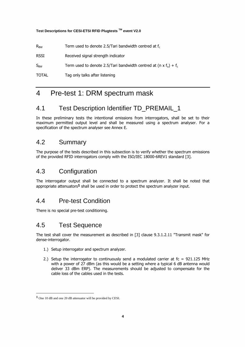
3.) Measure the integrated power for a 2.5/Tari bandwidth RBW centred at fc, an offset
frequency fo = 2.5/Tari, and a 2.5/Tari bandwidth SBW centred at (n × fo) + fc (integer n).
4.) The ratio of the integrated power P() in SBW to that in RBW with the Interrogator
transmitting random data2 shall not exceed the specified values:
|n| =1:10log10(P(SBW)/P(RBW)) < –30 dBch
|n| = 2: 10log10(P(SBW) / P(RBW)) < –60 dBch
|n| > 2: 10log10(P(SBW) / P(RBW)) < –65 dBch
Where P() denotes the total integrated power in the 2.5/Tari reference bandwidth.
This mask is shown graphically in figure 1, with dBch defined as dB referenced to the integrated power in the reference channel.
5.) Any anomalies in the results will be recorded
2 Random data may be done through anti-collision and identification commands as required. For ISO/IEC 18000-6C this would be
e.g. Select, Query, Query_Rep, Query_Adjust, ACK, NAK. For ISO/IEC18000-6TOTAL this would mean no data, as there is no forward link specified.
Test Descriptions for CESI-ETSI RFID Plugtests TM event V2.0
6
Figure 1: Transmit mask for dense-interrogator enviro nments
5 Pre-test 2: Multi-interrogator environment
5.1 Test Description Identifier TD_PREMAIL_2
5.2 Summary These tests shall cover the simultaneous operation of all participating interrogators, which shall
be located in close proximity to each other. Each interrogator shall continuously identify 30 tags.
In order to increase the challenge each interrogator may only select between 2 channels with
centre spacing of Test a) 500 kHz and Test b) 1 MHz.
5.3 Configuration For the test setup all interrogators participating in the whole tests shall be setup in a wide circle
and the antennas facing outwards of the circle. The antennas should be positioned 1 m above
the ground and directed outwards. Figure 2 shows an illustrative example but with the antenna
only placed 10 cm above ground.
Test Descriptions for CESI-ETSI RFID Plugtests TM event V2.0
7
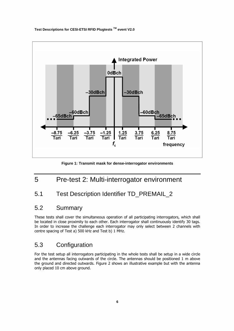
Each interrogator shall have 30 tags of the same protocol type 3(i.e. ISO/IEC 18000-6B, ISO/IEC
18000-6C or ISO/IEC 18000-6TOTAL) positioned randomly within the beamwidth of the antenna at distances of less than 3 m. Figure 2 shows an illustrative example with a smaller number of
tags.
The spacing between interrogators shall ensure that no interrogator reads tags associated with another interrogator. Depending on the tag performance this will require a spacing between
interrogators of at least 7 m.
Figure 2: Setup illustration – illustrative example of setup
3 It is expected that only a subset of available types will be provided for participation in the tests.
Test Descriptions for CESI-ETSI RFID Plugtests TM event V2.0
8
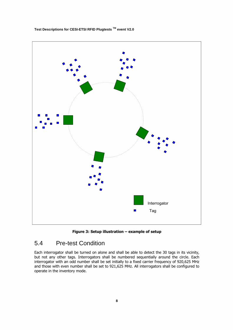
Interrogator
Tag
Figure 3: Setup illustration – example of setup
5.4 Pre-test Condition Each interrogator shall be turned on alone and shall be able to detect the 30 tags in its vicinity,
but not any other tags. Interrogators shall be numbered sequentially around the circle. Each
interrogator with an odd number shall be set initially to a fixed carrier frequency of 920,625 MHz and those with even number shall be set to 921,625 MHz. All interrogators shall be configured to
operate in the inventory mode.
Test Descriptions for CESI-ETSI RFID Plugtests TM event V2.0
9
5.5 Test Sequence 1.) Set radiated power of interrogators to 33dBm ERP (Note: might be reduced to 27dBm in
case of physical space limitations).
2.) Turn on interrogator sequentially in the sequence 1, 2, …, n. Note detection rate each
time a new interrogator is turned on.
3.) Repeat step 1 starting with interrogator 2 and turning on the other interrogators in sequence. Repeat this same process for the remaining interrogators. In case the
performance of the overall interrogator setup decreases when a particular interrogator is
turned on, then this shall be recorded.
4.) The test shall be repeated with odd number interrogators set to a fixed carrier frequency
of 921,125 MHz and those with even number shall be set to 921,625 MHz.
The final test report shall cover a list of problematic interrogators. Such issues are usually due to
out-of channel and spurious emissions that meet the requirements for the spectrum masks for
regulations and dense-interrogator operation, however, exceed the limits required for RFID
applications.
The final test report shall also record the behaviour of TOTAL tags in mixed environments.
For the test the number of identified tags and the time to identify those tags (all tags?) shall be
recorded.
6 Pre-test 3: Four channel plan
6.1 Test Description Identifier TD_PREMAIL_3
6.2 Summary These tests shall cover the simultaneous operation of all participating interrogators, which shall be located in close proximity to each other. Each of the at least 4 interrogators shall continuously
identify 30 tags. In order to increase the challenge each interrogator may only select between 2
channels with centre spacing of 1200 kHz according the European 4-channel plan as described in ETSI EN 302 208 and CEPT REC 70-03 Annex 11. The channel for operation shall be channels 4
and 7.
6.3 Configuration For the test setup all interrogators participating in the whole tests shall be setup in a wide circle and the antennas facing outwards of the circle. The antennas should be positioned 1 m above
the ground and directed outwards. Figure 2 shows an illustrative example but with the antenna
only placed 10 cm above ground.
Test Descriptions for CESI-ETSI RFID Plugtests TM event V2.0
10
Each interrogator shall have 30 tags of the same protocol type 4(i.e. ISO/IEC 18000-6B, ISO/IEC
18000-6C or ISO/IEC 18000-6TOTAL) positioned randomly within the beamwidth of the antenna at distances of less than 3 m. Figure 2 shows an illustrative example with a smaller number of
tags.
The spacing between interrogators shall ensure that no interrogator reads tags associated with another interrogator. Depending on the tag performance this will require a spacing between
interrogators of at least 7 m.
6.4 Pre-test Condition Each interrogator shall be turned on alone and shall be able to detect the 30 tags in its vicinity,
but not any other tags. Interrogators shall be numbered sequentially around the circle. Each
interrogator with an odd number shall be set initially to a fixed carrier frequency of 865.7 MHz
and those with even number shall be set to 866.9 MHz. All interrogators shall be configured to
operate in the inventory mode.
6.5 Test Sequence 1.) Set radiated power of interrogators to 33dBm ERP (Note: might be reduced to 27dBm in
case of physical space limitations).
2.) Turn on interrogator sequentially in the sequence 1, 2, …, n. Note detection rate each
time a new interrogator is turned on.
3.) Repeat step 1 starting with interrogator 2 and turning on the other interrogators in
sequence. Repeat this same process for the remaining interrogators. In case the
performance of the overall interrogator setup decreases when a particular interrogator is turned on, then this shall be recorded.
The final test report shall cover a list of problematic interrogators. Such issues are usually due to out-of channel and spurious emissions that meet the requirements for the spectrum masks for
regulations and dense-interrogator operation, however, exceed the limits required for RFID
applications.
The final test report shall also record the behaviour of TOTAL tags in mixed environments.
For the test the number of identified tags and the time to identify those tags (all tags?) shall be recorded.
4 It is expected that only a subset of available types will be provided for participation in the tests.

Test Descriptions for CESI-ETSI RFID Plugtests TM event V2.0
11
7 Application Set-up
7.1 Introduction The tests under the scope of this document generally may be split into two application set-ups. These set-ups are described in the following subsections.
7.2 Application Set-up 1: Dock Door Portal
7.2.1 Configuration
The dock door portal is used for manual movement tests. The dock door portal set-up basically comprises a dock door portal frame fitted with four antennas. Two antennas are mounted on the
horizontal member of the frame with the antenna parallel to and facing the floor. One antenna is
attached to each of the vertical columns of the portal. Each of these antennas is mounted at the
same height and facing inwards. Each interrogator under test is connected in turn to the antennas for the purpose of verifying satisfactory operation of the configurations. The test
scenarios using the dock door portal are:
• Mail Container (see TD_MAIL_1)
• Mail Case on a Cart (see TD_MAIL_2)
For all mail container tests only one pre selected antenna mounted on the horizontal member is
connected to the interrogator as described in sections 5. For all mail cases on a cart tests all four
antennas are connected to the interrogator as described in sections 6.
The portal including the antennas5 will be made available by CPST. The interrogators shall be
provided by the participating interrogator vendors (one per vendor). The tags shall be provided
by the participating tag vendors6. To eliminate one variable the same tags should be used with
all interrogators.
5 The use of antennas provided by the vendors shall be avoided unless the interrogator cannot use the provided antennas
at all.
6 ETSI will select the tags from the set of provided tags as required for the individual tests, considering that all interrogators see the same type of tags for a particular application test. Test types may vary between different application based on availability and requirements for the application (e.g. metal tags for metal environment and simple inlays for letter environment)
Test Descriptions for CESI-ETSI RFID Plugtests TM event V2.0
12
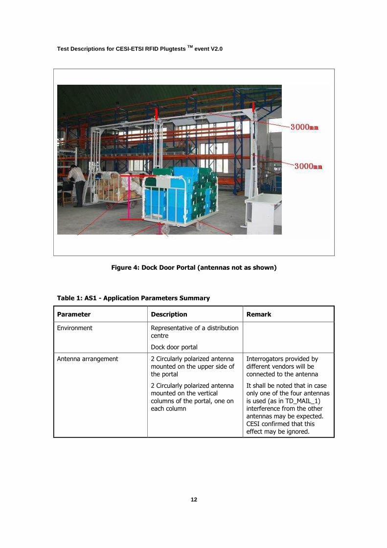
Figure 4: Dock Door Portal (antennas not as shown)
Table 1: AS1 - Application Parameters Summary
Parameter Description Remark
Environment Representative of a distribution
centre
Dock door portal
Antenna arrangement 2 Circularly polarized antenna
mounted on the upper side of
the portal
2 Circularly polarized antenna mounted on the vertical
columns of the portal, one on each column
Interrogators provided by
different vendors will be
connected to the antenna
It shall be noted that in case only one of the four antennas
is used (as in TD_MAIL_1) interference from the other
antennas may be expected.
CESI confirmed that this
effect may be ignored.

Test Descriptions for CESI-ETSI RFID Plugtests TM event V2.0
13
7.2.2 Description of Portal
The portal will be set-up as described below:
Internal Height: 3 metres
Internal Width: 3 metres
7.2.3 Locations of Antennas
Figure 4 indicates the set-up of the antennas in the portal. The actual set-up of the antennas will
be recorded during the tests. See Annex C for antenna specifications.
7.2.3.1 Feeder Cables
CESI will provide cables (cable loss is 0.5 dB/m) with a length of 6 m for connection of the
antennas and interrogators. The cables will be equipped with TNC connectors.

Test Descriptions for CESI-ETSI RFID Plugtests TM event V2.0
14
7.3 Application Set-up 2: Conveyor Portal
7.3.1 Configuration
The test application conveyor is used for two tests. The conveyor set-up basically comprises a
portal frame over a steel bedded conveyor with a steel reinforced belt with interlacing. Three
antennas in total are mounted on the portal frame. One antenna is mounted to the horizontal
member of the frame position with the antenna facing to the floor at an angle of 45 degrees. One
antenna is attached to each of the vertical columns of the portal facing inside the portal. The two test scenarios sharing the conveyor portal are:
• Mail case (see TD_MAIL_3)
• Mail bag (see TD_MAIL_4)
For all mail case tests only one antenna mounted on the horizontal member is connected to the
interrogator as described in sections 9. For all mail bag tests all three antennas are connected to the interrogator as described in sections 10.
The portal and the antennas mounted on the portal over the conveyor will be made available by CPST. The interrogators shall be provided by the participating interrogator vendors (one per
vendor). The tags shall be provided by the participating tag vendors and attached in advance of the Plugtests event.
Test Descriptions for CESI-ETSI RFID Plugtests TM event V2.0
15
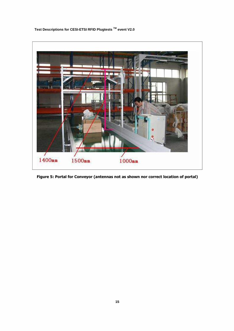
Figure 5: Portal for Conveyor (antennas not as shown nor correct location of portal)
Test Descriptions for CESI-ETSI RFID Plugtests TM event V2.0
16
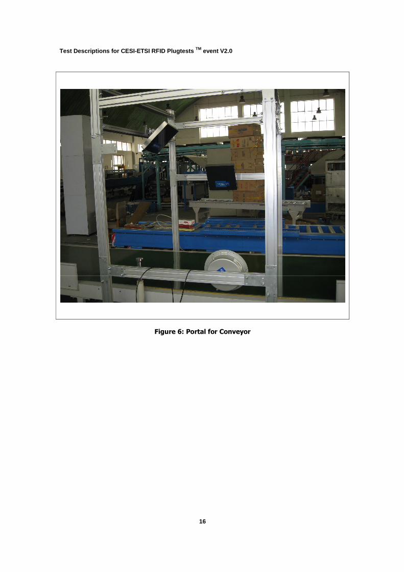
Figure 6: Portal for Conveyor
Test Descriptions for CESI-ETSI RFID Plugtests TM event V2.0
17
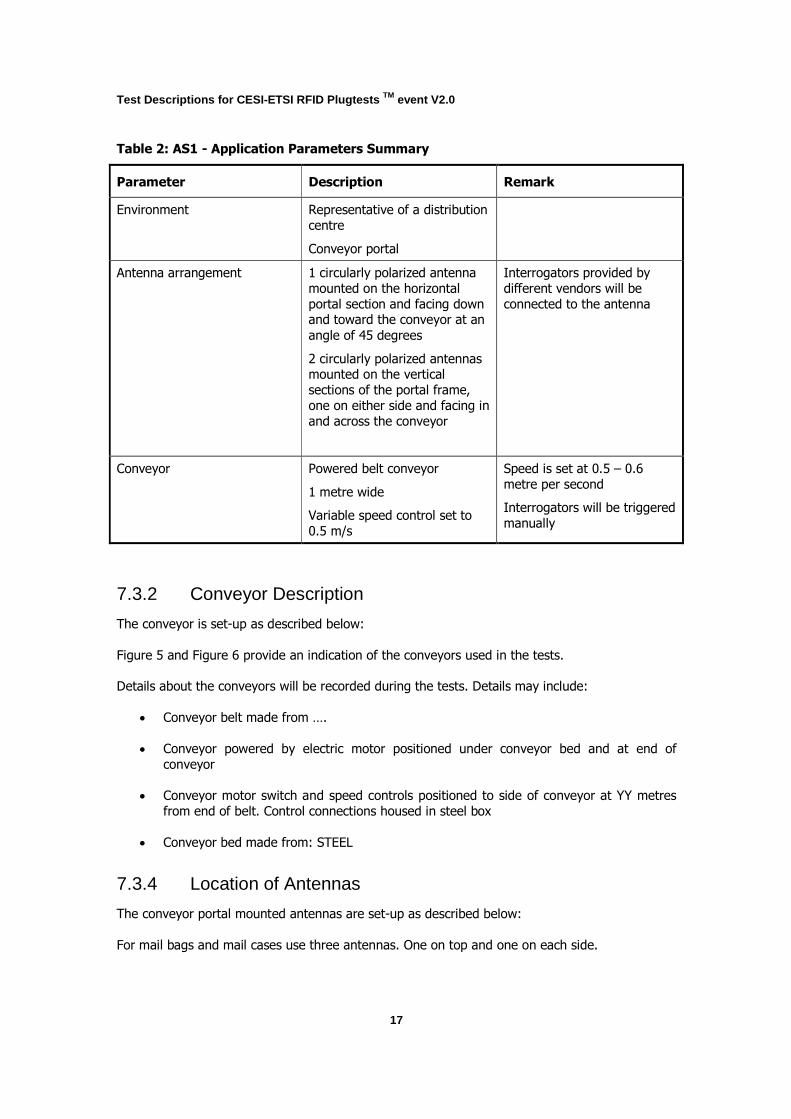
Table 2: AS1 - Application Parameters Summary
Parameter Description Remark
Environment Representative of a distribution
centre
Conveyor portal
Antenna arrangement 1 circularly polarized antenna
mounted on the horizontal
portal section and facing down and toward the conveyor at an
angle of 45 degrees
2 circularly polarized antennas mounted on the vertical
sections of the portal frame,
one on either side and facing in
and across the conveyor
Interrogators provided by
different vendors will be
connected to the antenna
Conveyor Powered belt conveyor
1 metre wide
Variable speed control set to
0.5 m/s
Speed is set at 0.5 – 0.6
metre per second
Interrogators will be triggered
manually
7.3.2 Conveyor Description
The conveyor is set-up as described below:
Figure 5 and Figure 6 provide an indication of the conveyors used in the tests.
Details about the conveyors will be recorded during the tests. Details may include:
• Conveyor belt made from ….
• Conveyor powered by electric motor positioned under conveyor bed and at end of
conveyor
• Conveyor motor switch and speed controls positioned to side of conveyor at YY metres
from end of belt. Control connections housed in steel box
• Conveyor bed made from: STEEL
7.3.4 Location of Antennas
The conveyor portal mounted antennas are set-up as described below:
For mail bags and mail cases use three antennas. One on top and one on each side.

Test Descriptions for CESI-ETSI RFID Plugtests TM event V2.0
18
Figure 5 and Figure 6 indicate the set-up of the antennas in the conveyor portal. The actual set-
up of the antennas will be recorded during the tests. See Annex C for antenna specifications.
CESI will provide cables (cable loss is 0.5 dB/m) with a length of 6 m for connection of the
antennas and interrogators. The cables will be equipped with TNC connectors.
Test Descriptions for CESI-ETSI RFID Plugtests TM event V2.0
19
8 Tests with Mail Container
8.1 Test Description Identifier TD_MAIL_1
8.2 Summary
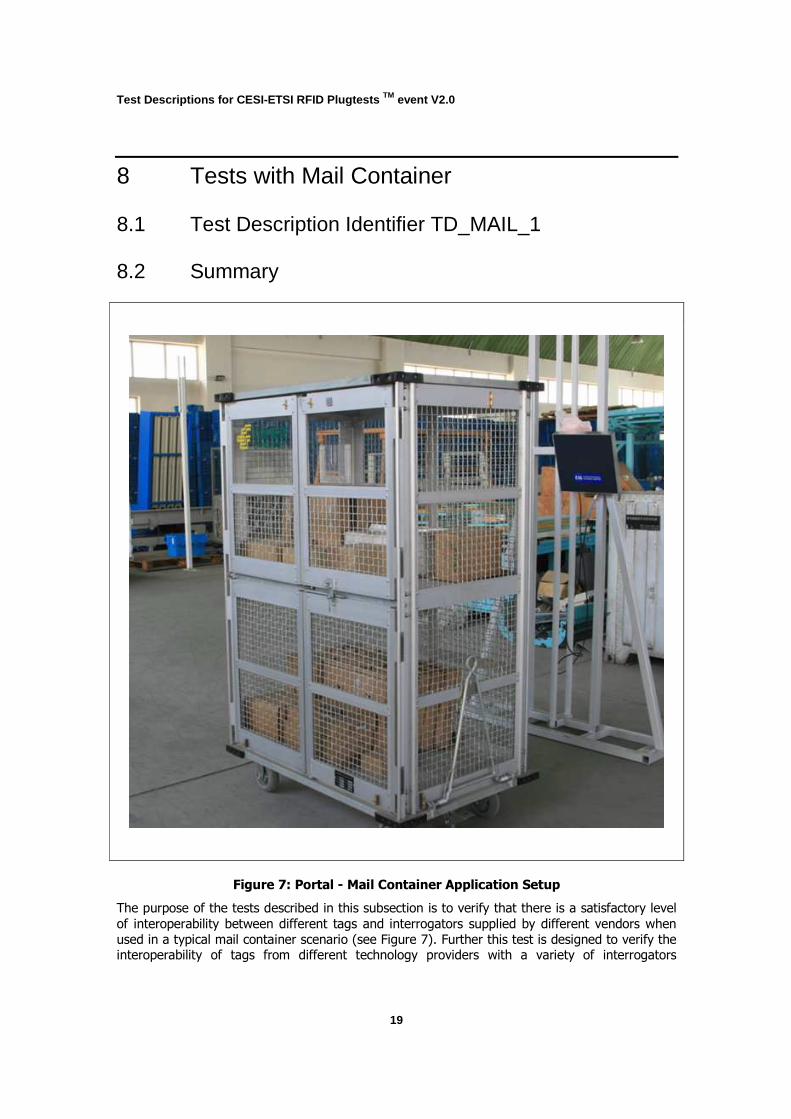
Figure 7: Portal - Mail Container Application Setup
The purpose of the tests described in this subsection is to verify that there is a satisfactory level
of interoperability between different tags and interrogators supplied by different vendors when
used in a typical mail container scenario (see Figure 7). Further this test is designed to verify the interoperability of tags from different technology providers with a variety of interrogators

Test Descriptions for CESI-ETSI RFID Plugtests TM event V2.0
20
operating protocols matching the tag and provided by a number of different vendors. The test
excludes an interference test of mixed protocol tags with different interrogators.
In the tests, a mail container is manually moved through a dock door portal. The container has a
tag optimized for metal on its topside. There are four antennas, two mounted on the upper side of the door portal and one mounted on each of the vertical columns as described in section 4,
however only one of the overhead antennas is pre selected for use in this test. The tag is
identified by the interrogator connected to one of the portal antennas mounted on the horizontal overhead frame.
8.3 Configuration The container shall be prepared in advance by CESI.
Table 3 summarises the application parameters for the container application set-up. Table 4
summarises the corresponding protocol parameters.
Test Descriptions for CESI-ETSI RFID Plugtests TM event V2.0
21
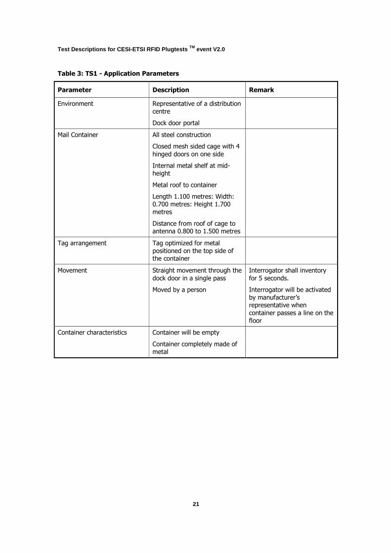
Table 3: TS1 - Application Parameters
Parameter Description Remark
Environment Representative of a distribution
centre
Dock door portal
Mail Container All steel construction
Closed mesh sided cage with 4
hinged doors on one side
Internal metal shelf at mid-
height
Metal roof to container
Length 1.100 metres: Width:
0.700 metres: Height 1.700
metres
Distance from roof of cage to antenna 0.800 to 1.500 metres
Tag arrangement Tag optimized for metal
positioned on the top side of the container
Movement Straight movement through the
dock door in a single pass
Moved by a person
Interrogator shall inventory
for 5 seconds.
Interrogator will be activated
by manufacturer’s representative when
container passes a line on the
floor
Container characteristics Container will be empty
Container completely made of
metal
Test Descriptions for CESI-ETSI RFID Plugtests TM event V2.0
22
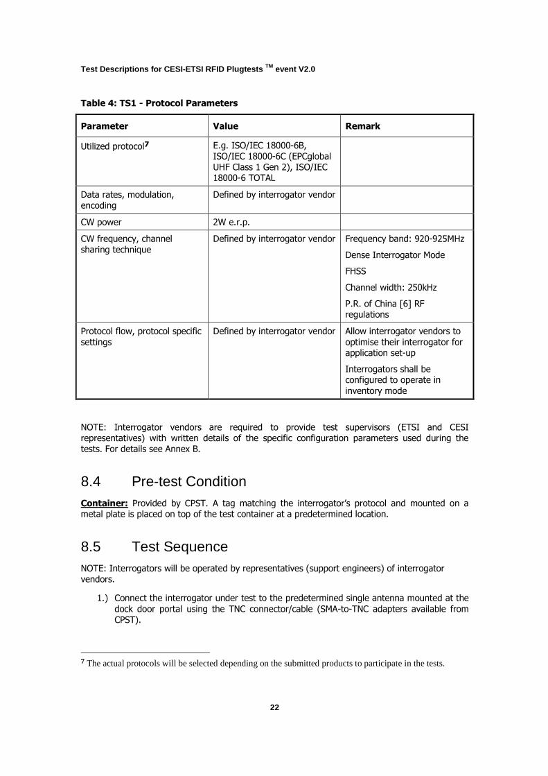
Table 4: TS1 - Protocol Parameters
Parameter Value Remark
Utilized protocol7
E.g. ISO/IEC 18000-6B,
ISO/IEC 18000-6C (EPCglobal
UHF Class 1 Gen 2), ISO/IEC 18000-6 TOTAL
Data rates, modulation,
encoding
Defined by interrogator vendor
CW power 2W e.r.p.
CW frequency, channel
sharing technique
Defined by interrogator vendor Frequency band: 920-925MHz
Dense Interrogator Mode
FHSS
Channel width: 250kHz
P.R. of China [6] RF regulations
Protocol flow, protocol specific
settings
Defined by interrogator vendor Allow interrogator vendors to
optimise their interrogator for application set-up
Interrogators shall be configured to operate in
inventory mode
NOTE: Interrogator vendors are required to provide test supervisors (ETSI and CESI
representatives) with written details of the specific configuration parameters used during the
tests. For details see Annex B.
8.4 Pre-test Condition Container: Provided by CPST. A tag matching the interrogator’s protocol and mounted on a metal plate is placed on top of the test container at a predetermined location.
8.5 Test Sequence NOTE: Interrogators will be operated by representatives (support engineers) of interrogator
vendors.
1.) Connect the interrogator under test to the predetermined single antenna mounted at the
dock door portal using the TNC connector/cable (SMA-to-TNC adapters available from
CPST).
7 The actual protocols will be selected depending on the submitted products to participate in the tests.

Test Descriptions for CESI-ETSI RFID Plugtests TM event V2.0
23
2.) Configure the interrogator to generate log files according to the guidelines in section 12
(the same format as the sample log file that was provided prior to the tests).
3.) Configure the interrogator under test for optimized operation in the portal container
application consistent with the technical requirements of P.R. of China [6] RF regulations.
4.) For evaluation of the results record the application set-up (dock door portal-container),
the interrogator under test (anonymised), the identity of the container used for the test,
and the test run number. The required data shall be recorded and linked manually during
parsing of the log files into the evaluation system. Representative of interrogator vendor to ensure that equipment is operating correctly under the given environmental
conditions.
5.) Move the container through the gate at typical speed of approximately 0.5 – 1.0 m/s.
a. The interrogator shall be started manually when the container crosses a line on
the floor.
b. The interrogator shall automatically stop inventory 5 seconds after starting.
c. Each tag inventory shall be recorded including timestamp, identifier, and RSSI
value.
6.) Repeat steps 4 and 5 five times (five test runs).
7.) Repeat steps 4 to 6 for each of the prepared containers (for each tag under test respectively).
8.) Repeat steps 1 to 7 for each interrogator under test.
Test Descriptions for CESI-ETSI RFID Plugtests TM event V2.0
24
9 Tests with Mail Cases on Cart
9.1 Test Description Identifier TD_MAIL_2
9.2 Summary
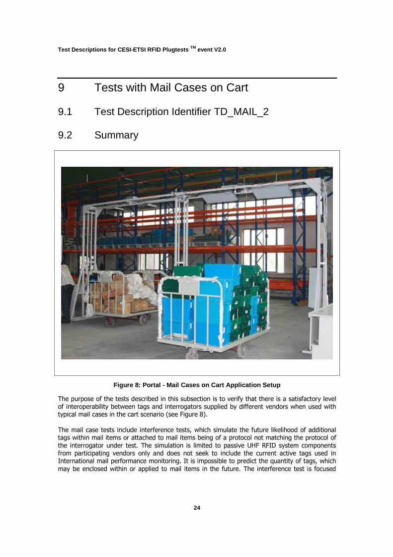
Figure 8: Portal - Mail Cases on Cart Application S etup
The purpose of the tests described in this subsection is to verify that there is a satisfactory level
of interoperability between tags and interrogators supplied by different vendors when used with typical mail cases in the cart scenario (see Figure 8).
The mail case tests include interference tests, which simulate the future likelihood of additional tags within mail items or attached to mail items being of a protocol not matching the protocol of
the interrogator under test. The simulation is limited to passive UHF RFID system components
from participating vendors only and does not seek to include the current active tags used in International mail performance monitoring. It is impossible to predict the quantity of tags, which
may be enclosed within or applied to mail items in the future. The interference test is focused

Test Descriptions for CESI-ETSI RFID Plugtests TM event V2.0
25
upon identifying the possible effects of multiple protocols on the read performance of different
interrogators.
In the tests, carts are manually moved through a dock door portal. Each cart includes sixty
tagged small mail cases. For all tests there are thirty tagged mail cases on each side of the mail cart. On each side of the mail cart the mail cases are stacked in five columns with each column
being six cases high. Four antennas are arranged around the portal and all are connected to the
interrogator under test. All tags matching the interrogator’s protocol shall be identified by the interrogator connected to the portal’s antennas. However the test objective will be to identify
each and every mail case tagged with a tag matching the protocol of the interrogator.
Tests commence with a cart containing tagged mail cases where all tags match the protocol of
the interrogator. For this test each mail case has two tags, one applied to each of the shorter sides of the small mail cases at a predefined location.
Interference tests involve mixing the population of tagged cases so that each case has two tags
matching the interrogator’s protocol and two tags not matching the interrogator’s protocol. The number of tests will be determined by the number of different tag types.
9.3 Configuration The carts and mail cases shall be prepared in advance by CPST.
There will be at least three carts each with 60 small mail cases of different combinations of tag
populations (basically tags from different vendors / of different type). With the exception that
different tags are attached to the cases, all carts and case positions shall be identical. The 60 mail cases shall include material typical for the application. Tags will be applied in advance of the
tests, one to each of the shorter sides of the mail cases. Details are given in section 8.4.
Prior to the Plugtests CPST should attach the tags, as specified, to each of the cases. They should
record details of the cart number, the case number together with the IDs of its tags and the
location of each case on the cart. CPST should confirm that all tags on all carts have been tested and are operational.
Table 5 summarises the application parameters for the mail cases on the cart application set-up.
Table 6 summarises the corresponding protocol parameters.
Test Descriptions for CESI-ETSI RFID Plugtests TM event V2.0
26
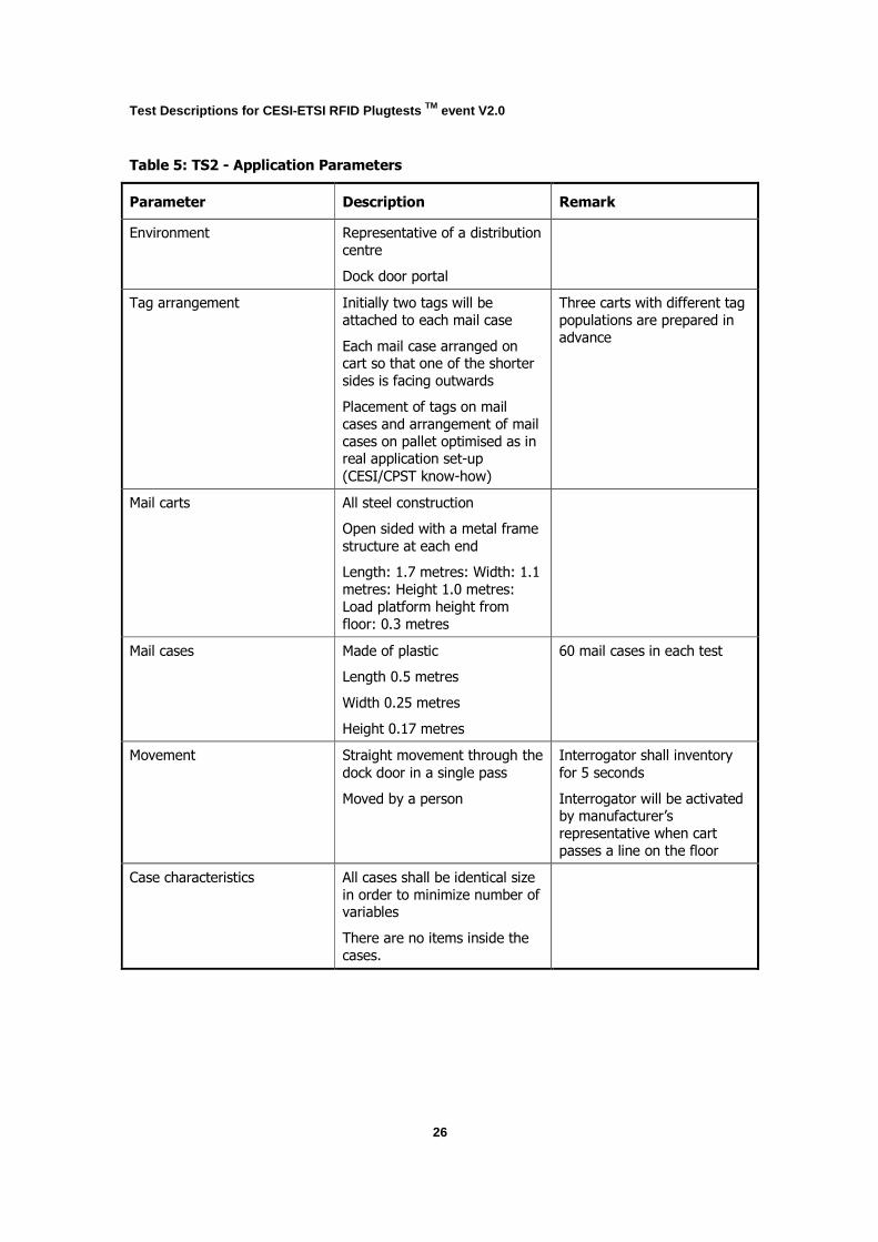
Table 5: TS2 - Application Parameters
Parameter Description Remark
Environment Representative of a distribution
centre
Dock door portal
Tag arrangement Initially two tags will be
attached to each mail case
Each mail case arranged on cart so that one of the shorter
sides is facing outwards
Placement of tags on mail
cases and arrangement of mail
cases on pallet optimised as in real application set-up
(CESI/CPST know-how)
Three carts with different tag
populations are prepared in
advance
Mail carts All steel construction
Open sided with a metal frame
structure at each end
Length: 1.7 metres: Width: 1.1
metres: Height 1.0 metres:
Load platform height from
floor: 0.3 metres
Mail cases Made of plastic
Length 0.5 metres
Width 0.25 metres
Height 0.17 metres
60 mail cases in each test
Movement Straight movement through the
dock door in a single pass
Moved by a person
Interrogator shall inventory
for 5 seconds
Interrogator will be activated by manufacturer’s
representative when cart
passes a line on the floor
Case characteristics All cases shall be identical size
in order to minimize number of variables
There are no items inside the
cases.

Test Descriptions for CESI-ETSI RFID Plugtests TM event V2.0
27
Table 6: TS2 - Protocol Parameters
Parameter Value Remark
Utilized protocol8 E.g. ISO/IEC 18000-6B,
ISO/IEC 18000-6C (EPCglobal
UHF Class 1 Gen 2), ISO/IEC 18000-6 TOTAL
Data rates, modulation,
encoding
Defined by interrogator vendor
CW power 2W e.r.p.
CW frequency, channel
sharing technique
Defined by interrogator vendor Frequency band: 920-925MHz
Dense Interrogator Mode
FHSS
Channel width: 250kHz
P.R. of China [6] RF regulations
Protocol flow, protocol specific
settings
Defined by interrogator vendor Allow interrogator vendors to
optimise their interrogator for application set-up
NOTE: Interrogator vendors are required to provide test supervisors (ETSI and CESI
representatives) with written details of the specific configuration parameters used during the
tests. For details see Annex B.
9.4 Pre-test Condition Mail cases on cart: Provided by CPST. The carts for testing are prepared prior to the tests.
With the exception that different tags are attached to cases, all carts are identical. The carts shall
each carry sixty tagged cases. All cases have at least one of their sides visible. Two carts each
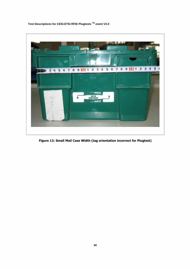
with sixty tagged cases having one tag on each of the cases shorter sides (one hundred and twenty tags in total) shall be prepared for each tag type. The placement of tags shall be as
indicated in Figure 12 (see Rafsec tag). The arrangement of cases on carts shall be predefined
(CESI/CPST know-how).
Each interrogator set-up for testing shall complete all selected tag tests at the Dock Door Portal
before moving on to test the next interrogator. The tests shall involve each loaded mail cart passing through the portal five times. The direction of the cart shall alternate representative of a
full cart leaving and entering a facility. Of the five tests this provides three passes in one direction and two in the opposite direction. On each pass a unique electronic record of the test shall be
created.
All mail cases with homogenous populations of tags matching with the interrogator protocol shall be tested sequentially. Subsequently mail carts with mail cases having tags of different protocols
8 The actual protocols will be selected depending on the submitted products to participate in the tests.
Test Descriptions for CESI-ETSI RFID Plugtests TM event V2.0
28
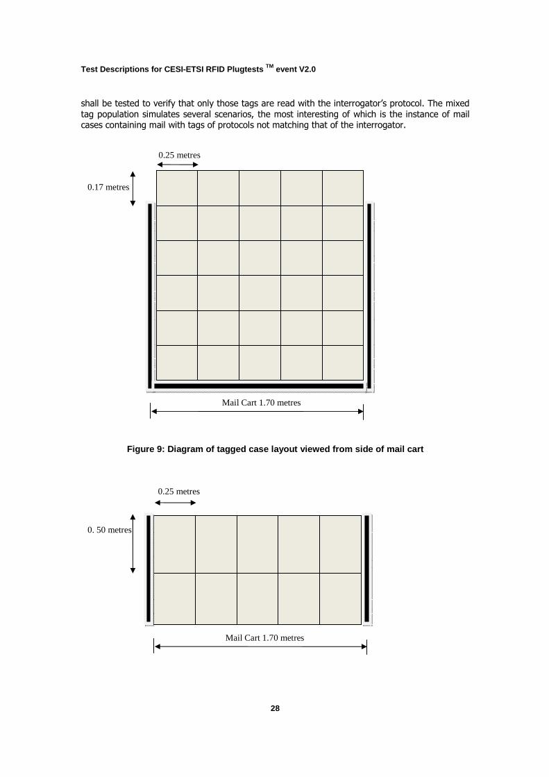
shall be tested to verify that only those tags are read with the interrogator’s protocol. The mixed
tag population simulates several scenarios, the most interesting of which is the instance of mail cases containing mail with tags of protocols not matching that of the interrogator.
Figure 9: Diagram of tagged case layout viewed from s ide of mail cart
0.25 metres
Mail Cart 1.70 metres
0.17 metres
0.25 metres
Mail Cart 1.70 metres
0. 50 metres
Test Descriptions for CESI-ETSI RFID Plugtests TM event V2.0
29
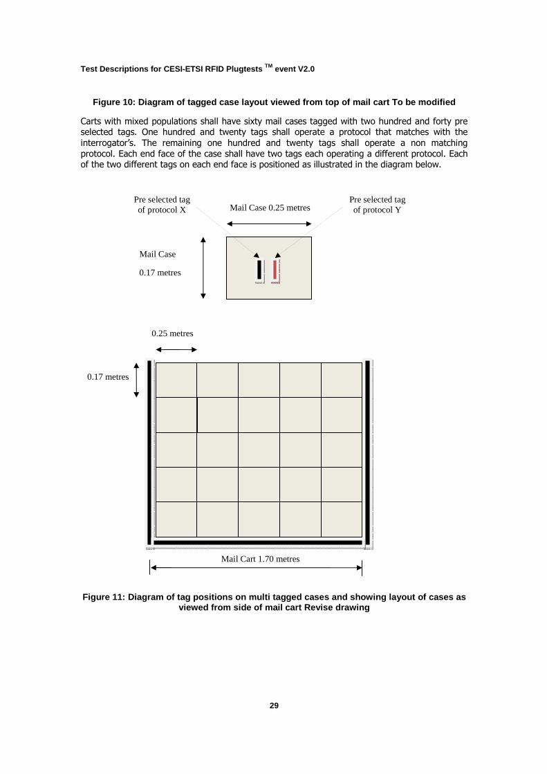
Figure 10: Diagram of tagged case layout viewed from top of mail cart To be modified
Carts with mixed populations shall have sixty mail cases tagged with two hundred and forty pre selected tags. One hundred and twenty tags shall operate a protocol that matches with the
interrogator’s. The remaining one hundred and twenty tags shall operate a non matching
protocol. Each end face of the case shall have two tags each operating a different protocol. Each of the two different tags on each end face is positioned as illustrated in the diagram below.
Figure 11: Diagram of tag positions on multi tagged c ases and showing layout of cases as viewed from side of mail cart Revise drawing
0.25 metres
Mail Cart 1.70 metres
0.17 metres
Mail Case 0.25 metres
Mail Case
0.17 metres
Pre selected tag of protocol Y
Pre selected tag of protocol X
Test Descriptions for CESI-ETSI RFID Plugtests TM event V2.0
30
Figure 12: Small Mail Case Width (tag orientation incorrect for Plugtest)
Test Descriptions for CESI-ETSI RFID Plugtests TM event V2.0
31
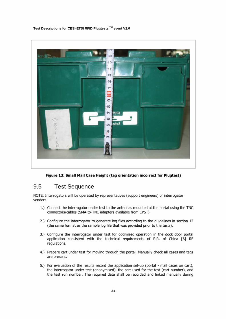
Figure 13: Small Mail Case Height (tag orientation incorrect for Plugtest)
9.5 Test Sequence NOTE: Interrogators will be operated by representatives (support engineers) of interrogator
vendors.
1.) Connect the interrogator under test to the antennas mounted at the portal using the TNC
connectors/cables (SMA-to-TNC adapters available from CPST).
2.) Configure the interrogator to generate log files according to the guidelines in section 12 (the same format as the sample log file that was provided prior to the tests).
3.) Configure the interrogator under test for optimized operation in the dock door portal
application consistent with the technical requirements of P.R. of China [6] RF
regulations.
4.) Prepare cart under test for moving through the portal. Manually check all cases and tags
are present.
5.) For evaluation of the results record the application set-up (portal - mail cases on cart),
the interrogator under test (anonymised), the cart used for the test (cart number), and
the test run number. The required data shall be recorded and linked manually during

Test Descriptions for CESI-ETSI RFID Plugtests TM event V2.0
32
parsing of the log files into the evaluation system. Representative of interrogator vendor
to ensure that equipment is operating correctly under the given environmental conditions.
6.) Move the cart through the gate at speed of 05 – 1.0 m/s. The interrogator shall be started manually when the cart crosses a line on the floor.
d. The interrogator shall automatically stop inventory 5 seconds after starting.
e. Each tag inventory shall be recorded including timestamp, EPC equivalent (CPST to define), antenna number, and RSSI value.
7.) Repeat steps 5 and 6 five times (five test runs). The direction of the cart shall alternate representative of a full cart leaving and entering a facility.
8.) Repeat steps 4 to 7 for each of the prepared carts.
9.) Repeat steps 1 to 8 for each interrogator under test.
Test Descriptions for CESI-ETSI RFID Plugtests TM event V2.0
33
10 Conveyor Tests with Mail Cases
10.1 Test Description Identifier TD_MAIL_3
10.2 Summary
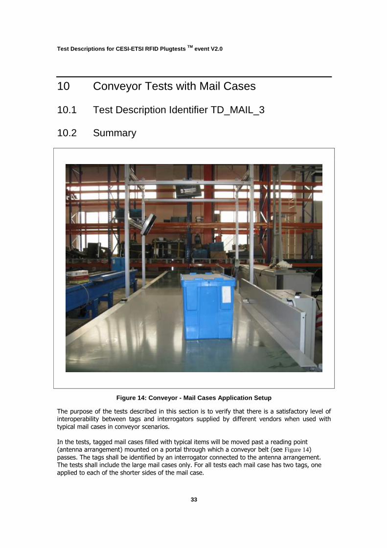
Figure 14: Conveyor - Mail Cases Application Setup
The purpose of the tests described in this section is to verify that there is a satisfactory level of interoperability between tags and interrogators supplied by different vendors when used with
typical mail cases in conveyor scenarios.
In the tests, tagged mail cases filled with typical items will be moved past a reading point (antenna arrangement) mounted on a portal through which a conveyor belt (see Figure 14) passes. The tags shall be identified by an interrogator connected to the antenna arrangement. The tests shall include the large mail cases only. For all tests each mail case has two tags, one
applied to each of the shorter sides of the mail case.
Test Descriptions for CESI-ETSI RFID Plugtests TM event V2.0
34
10.3 Configuration The cases shall be filled with typical items and will be made available by CESI/CPST (prepared in
advance - see section 7.3. Mail cases will be manually placed on the moving conveyor with case to case separation of approximately 10 cm and with defined orientations of the tags to the
antenna.
Table 7 summarises the application parameters for set-up of the mail cases in the conveyor
application. Table 8 summarises the corresponding protocol parameters.
Table 7: TS3 - Application Parameters
Parameter Description Remark
Environment Representative of a conveyor
system for mail case handling
Tag arrangement for tests Tags attached to cases (two
per case)
A tag of identical type and from same vendor attached to
each end of each case
Cases distributed evenly on
conveyor at a separation of 0.1
metres
5 large cases shall be
prepared in advance
Tag position pre defined
Mail cases (large) Made of plastic
Length 0.500 metres
Width 0.270 metres
Height 0.310 metres
10 cases per test
Movement Use typical speed (see section 6)
Five passes through test point
Case characteristics Cases shall include mixed items
(materials) typical for
application
Test Descriptions for CESI-ETSI RFID Plugtests TM event V2.0
35
Table 8: TS3 - Protocol Parameters
Parameter Value Remark
Utilized protocol9
E.g. ISO/IEC 18000-6B,
ISO/IEC 18000-6C (EPCglobal
UHF Class 1 Gen 2), ISO/IEC 18000-6 TOTAL
Data rates, modulation,
encoding
Defined by interrogator vendor DRM (Miller sub carrier
encoding) required
CW power 2W e.r.p.
CW frequency, channel
sharing technique
Defined by interrogator vendor Frequency band: 920-925MHz
Dense Interrogator Mode
FHSS
Channel width: 250kHz
P.R. of China [6] RF regulations
Protocol flow, protocol specific
settings
Defined by interrogator vendor Allow interrogator vendors to
optimise interrogator for application
Interrogators shall be configured to operate in
inventory mode
NOTE: Interrogator vendors are required to provide test supervisors (ETSI and CESI
representatives) with written details of the specific configuration parameters used during the
tests. For details see Annex B.
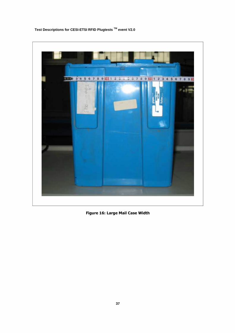
10.4 Pre-test Condition Cases: Provided by CESI. The cases for testing shall be prepared prior to the tests. Each case shall be fitted with two tags, one on each of the smaller sides and at pre determined positions.
Placement of tags shall be as indicated in Figure 16 (see Rafsec tag). There shall be at least ten
cases for each tag type used in the tests.
CPST should record the case number of each case together with the IDs of its tags and confirm
that all tags have been tested and are operational.
Information about the cases shall be fed into the evaluation system prior to the tests. This shall
include the identifiers of the individual tags and their sequence on the conveyor belt. In order to be able to do this, tags will be placed in partly transparent mail bags in order to be able to see
the tags.
9 The actual protocols will be selected depending on the submitted products to participate in the tests.
Test Descriptions for CESI-ETSI RFID Plugtests TM event V2.0
36
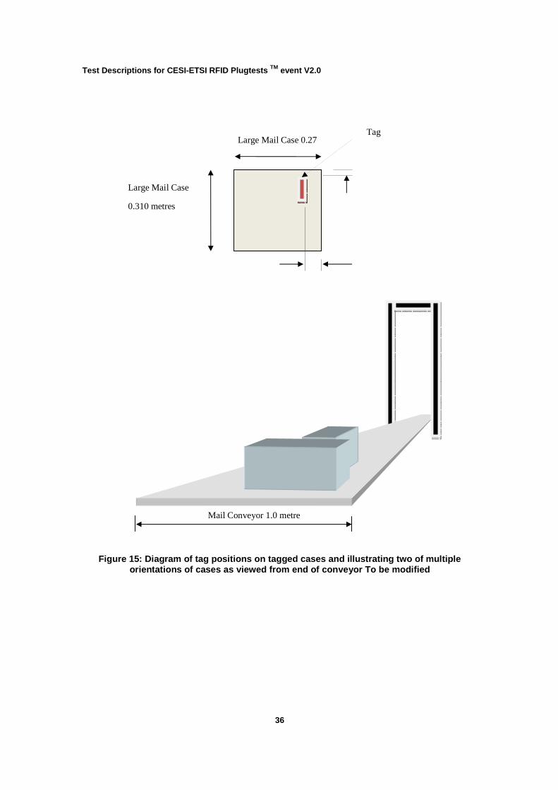
Figure 15: Diagram of tag positions on tagged cases and illustrating two of multiple orientations of cases as viewed from end of conveyor To be modified
Mail Conveyor 1.0 metre
Large Mail Case 0.27 metres
Large Mail Case
0.310 metres
Tag
Test Descriptions for CESI-ETSI RFID Plugtests TM event V2.0
37
Figure 16: Large Mail Case Width
Test Descriptions for CESI-ETSI RFID Plugtests TM event V2.0
38
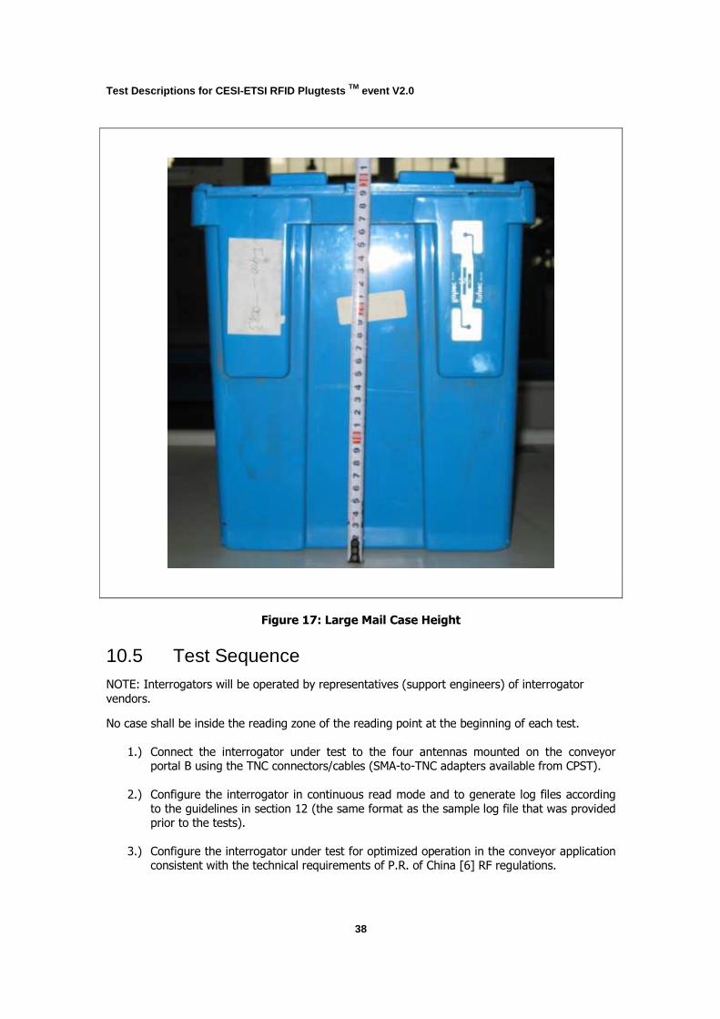
Figure 17: Large Mail Case Height
10.5 Test Sequence NOTE: Interrogators will be operated by representatives (support engineers) of interrogator
vendors.
No case shall be inside the reading zone of the reading point at the beginning of each test.
1.) Connect the interrogator under test to the four antennas mounted on the conveyor portal B using the TNC connectors/cables (SMA-to-TNC adapters available from CPST).
2.) Configure the interrogator in continuous read mode and to generate log files according
to the guidelines in section 12 (the same format as the sample log file that was provided prior to the tests).
3.) Configure the interrogator under test for optimized operation in the conveyor application consistent with the technical requirements of P.R. of China [6] RF regulations.
Test Descriptions for CESI-ETSI RFID Plugtests TM event V2.0
39
4.) Start operation of the interrogator and light curtain.
5.) For evaluation of the results record the application set-up (mail cases on conveyor) and
the interrogator under test (anonymised). The required data shall be recorded and linked
to the log file manually during parsing of the log files into the evaluation system. Representative of interrogator vendor to ensure that equipment is operating correctly
under the given environmental conditions.
6.) Manually place each of the ten mail cases one-by-one onto the static conveyor ensuring
that:
a. The first four cases have their tags facing the end and beginning of the conveyor
b. The next four have their tags facing across the width of the conveyor
c. The last two have their tags facing approximately forty-five degrees to the conveyor ends/sides
NOTE: No tag shall face the conveyor belt or face vertically upwards. Gaps
between cases are kept consistent at approximately three metres.
7.) Switch-on and start the conveyor.
a. Each tag inventory shall be recorded including timestamp, identifier, antenna number, and RSSI value.
8.) Once all tagged cases have passed through the conveyor portal stop the conveyor.
9.) Repeat steps 5 to 8 for each tag matching with the interrogator under test and submitted for testing.
10.) Repeat steps 1 to 9 for each interrogator under test
Test Descriptions for CESI-ETSI RFID Plugtests TM event V2.0
40
11 Conveyor Tests with Mail Bags
11.1 Test Description Identifier TD_MAIL_4
11.2 Summary
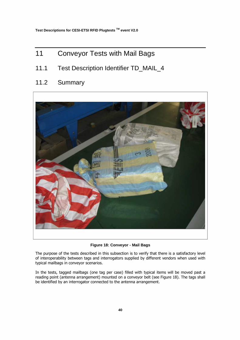
Figure 18: Conveyor - Mail Bags
The purpose of the tests described in this subsection is to verify that there is a satisfactory level
of interoperability between tags and interrogators supplied by different vendors when used with
typical mailbags in conveyor scenarios.
In the tests, tagged mailbags (one tag per case) filled with typical items will be moved past a
reading point (antenna arrangement) mounted on a conveyor belt (see Figure 18). The tags shall be identified by an interrogator connected to the antenna arrangement.
Test Descriptions for CESI-ETSI RFID Plugtests TM event V2.0
41
This test does not include an interference test. This is because the interference tests have
already been completed with the mail cases and because this test focuses upon random tag orientations with respect to interrogator antennas.
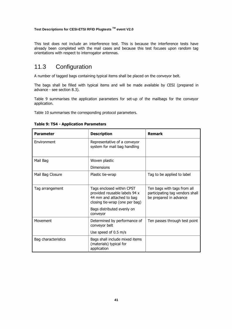
11.3 Configuration A number of tagged bags containing typical items shall be placed on the conveyor belt.
The bags shall be filled with typical items and will be made available by CESI (prepared in advance - see section 8.3).
Table 9 summarises the application parameters for set-up of the mailbags for the conveyor application.
Table 10 summarises the corresponding protocol parameters.
Table 9: TS4 - Application Parameters
Parameter Description Remark
Environment Representative of a conveyor
system for mail bag handling
Mail Bag Woven plastic
Dimensions
Mail Bag Closure Plastic tie-wrap
Tag to be applied to label
Tag arrangement Tags enclosed within CPST
provided reusable labels 94 x
44 mm and attached to bag
closing tie-wrap (one per bag)
Bags distributed evenly on
conveyor
Ten bags with tags from all
participating tag vendors shall
be prepared in advance
Movement Determined by performance of
conveyor belt
Use speed of 0.5 m/s
Ten passes through test point
Bag characteristics Bags shall include mixed items
(materials) typical for
application

Test Descriptions for CESI-ETSI RFID Plugtests TM event V2.0
42
Table 10: TS4 - Protocol Parameters
Parameter Value Remark
Utilized protocol10
E.g. ISO/IEC 18000-6B,
ISO/IEC 18000-6C (EPCglobal
UHF Class 1 Gen 2), ISO/IEC 18000-6 TOTAL
Data rates, modulation,
encoding
Defined by interrogator vendor DRM (Miller sub carrier
encoding) required
CW power 2W e.r.p.
CW frequency, channel
sharing technique
Defined by interrogator vendor Frequency band: 920-925MHz
Dense Interrogator Mode
FHSS
Channel width: 250kHz
P.R. of China [6] RF regulations
Protocol flow, protocol specific
settings
Defined by interrogator vendor Allow interrogator vendors to
optimise interrogator for application
Interrogators shall be configured to operate in
inventory mode
NOTE: Interrogator vendors are required to provide test supervisors (ETSI and CESI
representatives) with written details of the specific configuration parameters used during the
tests. For details see Annex B.
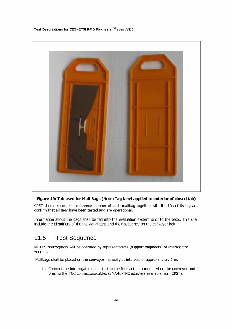
11.4 Pre-test Condition Bags: Provided by CESI. The bags for testing are prepared prior to the tests. Each bag is fitted with a single tag, which is applied to the bag closing tie (reference Figure 19) There are ten bags
for each tag type used in the tests. Each bag is visibly uniquely identifiable.
10 The actual protocols will be selected depending on the submitted products to participate in the tests.
Test Descriptions for CESI-ETSI RFID Plugtests TM event V2.0
43
Figure 19: Tab used for Mail Bags (Note: Tag label applied to exterior of closed tab)
CPST should record the reference number of each mailbag together with the IDs of its tag and confirm that all tags have been tested and are operational.
Information about the bags shall be fed into the evaluation system prior to the tests. This shall include the identifiers of the individual tags and their sequence on the conveyor belt.
11.5 Test Sequence NOTE: Interrogators will be operated by representatives (support engineers) of interrogator
vendors.
Mailbags shall be placed on the conveyor manually at intervals of approximately 1 m.
1.) Connect the interrogator under test to the four antenna mounted on the conveyor portal
B using the TNC connectors/cables (SMA-to-TNC adapters available from CPST).

Test Descriptions for CESI-ETSI RFID Plugtests TM event V2.0
44
2.) Configure the interrogator to generate log files according to the guidelines in section 12
(the same format as the sample log file that was provided prior to the tests).
3.) Configure the interrogator under test in continuous read mode and for optimized
operation in the conveyor application consistent with the technical requirements of P.R. of China [6] RF regulations.
4.) Switch-on and start the conveyor.
5.) Start operation of the interrogator and the light curtain.
6.) For evaluation of the results record the application set-up (mail bags on conveyor) and
the interrogator under test (anonymised). The required data shall be recorded and linked to the log file manually during parsing of the log files into the evaluation system. The
representative of the interrogator vendor shall ensure that the equipment is operating
correctly under the given environmental conditions.
7.) Manually place each of the ten mailbags one-by-one onto the moving conveyor ensuring
that:
a. Gaps between mailbags are kept consistent at approximately one metre.
NOTE: 2 people to load mailbags at the conveyor and 2 other to offload, as otherwise there will be a pile of bags on the floor right next to the portal. This
may affect performance.
b. Each tag inventory shall be recorded including timestamp, identifier, antenna number, and RSSI value.
8.) Repeat steps 7 to 8 for each tag submitted for test.
9.) Repeat steps 1 to 9 for each interrogator under test
Test Descriptions for CESI-ETSI RFID Plugtests TM event V2.0
45
12 ID Allocation and Evaluation System
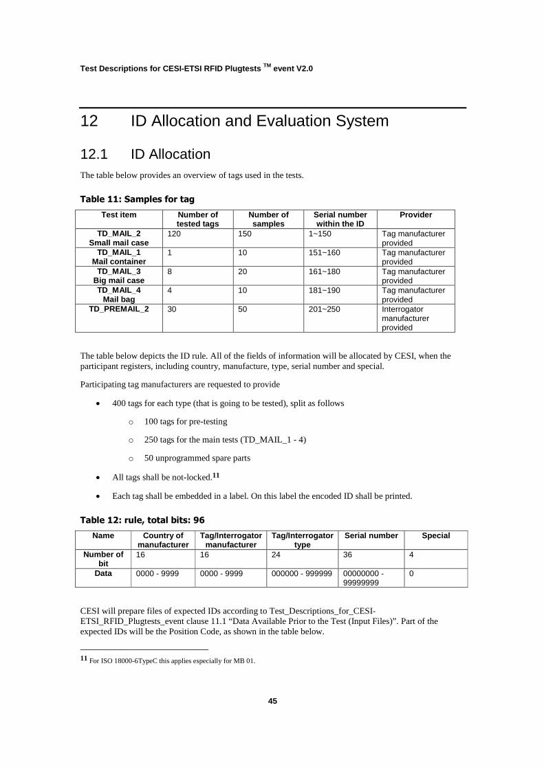
12.1 ID Allocation The table below provides an overview of tags used in the tests.
Table 11: Samples for tag
Test item Number of tested tags
Number of samples
Serial number within the ID
Provider
TD_MAIL_2 Small mail case
120 150 1~150 Tag manufacturer provided
TD_MAIL_1 Mail container
1 10 151~160 Tag manufacturer provided
TD_MAIL_3 Big mail case
8 20 161~180 Tag manufacturer provided
TD_MAIL_4 Mail bag
4 10 181~190 Tag manufacturer provided
TD_PREMAIL_2 30 50 201~250 Interrogator manufacturer provided
The table below depicts the ID rule. All of the fields of information will be allocated by CESI, when the participant registers, including country, manufacture, type, serial number and special.
Participating tag manufacturers are requested to provide
• 400 tags for each type (that is going to be tested), split as follows
o 100 tags for pre-testing
o 250 tags for the main tests (TD_MAIL_1 - 4)
o 50 unprogrammed spare parts
• All tags shall be not-locked.11
• Each tag shall be embedded in a label. On this label the encoded ID shall be printed.
Table 12: rule, total bits: 96
Name Country of manufacturer
Tag/Interrogator manufacturer
Tag/Interrogator type
Serial number Special
Number of bit
16 16 24 36 4
Data 0000 - 9999 0000 - 9999 000000 - 999999 00000000 - 99999999
0
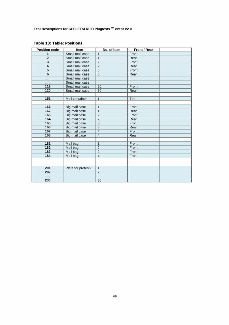
CESI will prepare files of expected IDs according to Test_Descriptions_for_CESI-ETSI_RFID_Plugtests_event clause 11.1 “Data Available Prior to the Test (Input Files)”. Part of the expected IDs will be the Position Code, as shown in the table below.
11 For ISO 18000-6TypeC this applies especially for MB 01.
Test Descriptions for CESI-ETSI RFID Plugtests TM event V2.0
46
Table 13: Table: Positions
Position code Item No. of Item Front / Rear 1 Small mail case 1 Front 2 Small mail case 1 Rear 3 Small mail case 2 Front 4 Small mail case 2 Rear 5 Small mail case 3 Front 6 Small mail case 3 Rear
….. Small mail case ….. Small mail case 119 Small mail case 60 Front 120 Small mail case 60 Rear
151 Mail container 1 Top
161 Big mail case 1 Front 162 Big mail case 1 Rear 163 Big mail case 2 Front 164 Big mail case 2 Rear 165 Big mail case 3 Front 166 Big mail case 3 Rear 167 Big mail case 4 Front 168 Big mail case 4 Rear
181 Mail bag 1 Front 182 Mail bag 2 Front 183 Mail bag 3 Front 184 Mail bag 4 Front
201 Plate for pretest2 1 202 2 …. 230 30
Test Descriptions for CESI-ETSI RFID Plugtests TM event V2.0
47
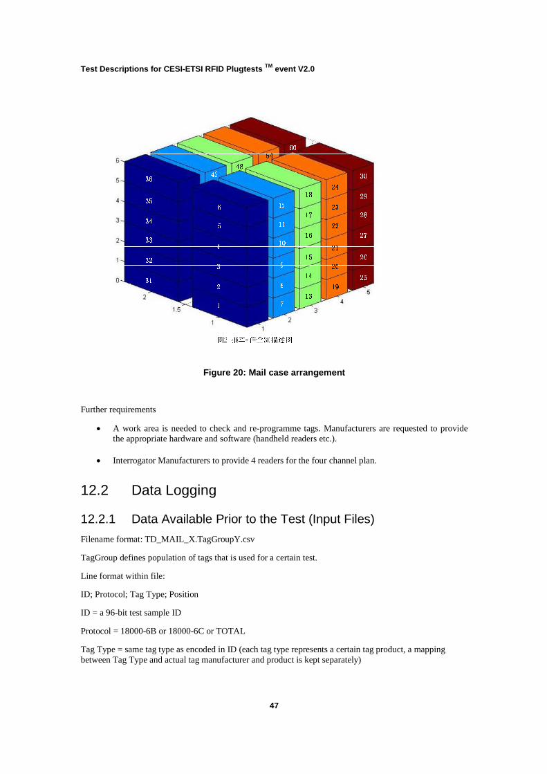
Figure 20: Mail case arrangement
Further requirements
• A work area is needed to check and re-programme tags. Manufacturers are requested to provide the appropriate hardware and software (handheld readers etc.).
• Interrogator Manufacturers to provide 4 readers for the four channel plan.
12.2 Data Logging
12.2.1 Data Available Prior to the Test (Input Files)
Filename format: TD_MAIL_X.TagGroupY.csv
TagGroup defines population of tags that is used for a certain test.
Line format within file:
ID; Protocol; Tag Type; Position
ID = a 96-bit test sample ID
Protocol = 18000-6B or 18000-6C or TOTAL
Tag Type = same tag type as encoded in ID (each tag type represents a certain tag product, a mapping between Tag Type and actual tag manufacturer and product is kept separately)
Test Descriptions for CESI-ETSI RFID Plugtests TM event V2.0
48
12.2.1.1 TD_MAIL_1 (Container/Portal)
TagGroup = just one tag per test = just one line in the input file
12.2.1.2 TD_MAIL_2 (Cart/Cases/Portal)
TagGroup = population of tags that are arranged on the cart for a certain test (different populations - homogenous and mixed - might be used) to identify the tag provider and tag type and mixture mode.
12.2.1.3 TD_MAIL_3 (Cases/Conveyor)
TagGroup = population of tags that are sent through the reading point (conveyor portal) for a certain test case to identify the tag provider and tag type.
12.2.1.4 TD_MAIL_4 (Bags/Conveyor)
TagGroup = population of tags that are sent through the reading point (conveyor portal) for a certain test case to identify the tag provider and tag type.
12.2.2 Interrogator Log Files (Output Files)
Filename Format: TD_MAIL_X.InterrogatorZ.TagGroupY.TestrunB.csv
Example: TD_MAIL_1.Interrogator1.TagGroup3.Testrun4
Line format within file:
Timestamp; ID; RSSI value; any other additional vendor specific information
Timestamp = time(iso8601)
ID = 96 bit test sample identifier
RSSI = rssi value in dBm
The log file is to be fed manually into the evaluation system (e.g. via USB stick). There is no Data Caption Tool, i.e. every interrogator vendor shall provide the capability to create a log file.
Manufacturers shall supply suitable software and any specialist hardware necessary to drive the interrogators to provide log files.
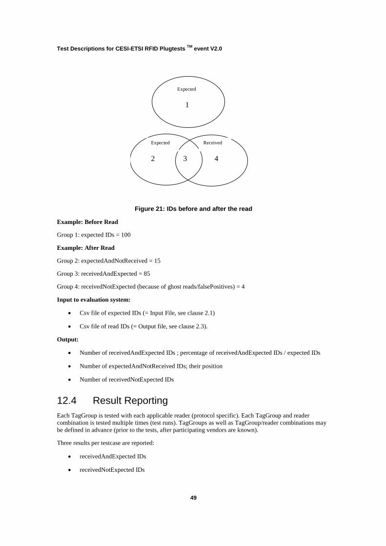
12.3 Result Analysis The figure below shows the batch of expected IDs before the read, and the different batches of IDs after the read.
Test Descriptions for CESI-ETSI RFID Plugtests TM event V2.0
49
1
2 4 3
Expected
Expected Received
Figure 21: IDs before and after the read
Example: Before Read
Group 1: expected IDs = 100
Example: After Read
Group 2: expectedAndNotReceived = 15
Group 3: receivedAndExpected = 85
Group 4: receivedNotExpected (because of ghost reads/falsePositives) = 4
Input to evaluation system:
• Csv file of expected IDs (= Input File, see clause 2.1)
• Csv file of read IDs (= Output file, see clause 2.3).
Output:
• Number of receivedAndExpected IDs ; percentage of receivedAndExpected IDs / expected IDs
• Number of expectedAndNotReceived IDs; their position
• Number of receivedNotExpected IDs
12.4 Result Reporting Each TagGroup is tested with each applicable reader (protocol specific). Each TagGroup and reader combination is tested multiple times (test runs). TagGroups as well as TagGroup/reader combinations may be defined in advance (prior to the tests, after participating vendors are known).
Three results per testcase are reported:
• receivedAndExpected IDs
• receivedNotExpected IDs

Test Descriptions for CESI-ETSI RFID Plugtests TM event V2.0
50
• receivedNotExpected IDs
Test Descriptions for CESI-ETSI RFID Plugtests TM event V2.0
51
Annex A Influences on Tag/Tag Interrogator Interoperability
A.1 Introduction
The main factors influencing tag interoperability are the application scenario, protocol parameters, and individual tag characteristics. Each of these factors is addressed in detail in the
following sub-sections However due to the large number of variables associated with application
scenarios and protocol parameters, it is only possible to cover the main factors influencing tag behaviour. Since there could be issues in assigning interrogator related characteristics either to
the application scenario or to the protocol parameters, the following convention is adopted. Software definable characteristics are assigned to the protocol parameters while all
others are assigned to the application scenario.
A.2 Application Scenario
The application scenario describes the set-up in which an RFID interrogator and tags are used.
The main characteristics of an application scenario include:
• Environment
o All aspects that have a certain influence on an application but are not part of the
application itself (like surrounding material, noise sources of any kind e.g. mobile phones)
• Interrogator antenna arrangement
o Position and orientation of the interrogator antennas in a set-up
o Number of interrogator antennas
o Type of interrogator antennas
• Tag arrangement
o Position and orientation of the tags in a set-up
o Number of tags
o Type of tags (different vendors/models)
• Relative movement between interrogator antennas and tags
o Speed
o Path
Test Descriptions for CESI-ETSI RFID Plugtests TM event V2.0
52
� E.g. pallet moving through portal (tags moving)
� E.g. handheld interrogator (interrogator antenna moving)
• Pallet / Case / Item characteristics
o Materials
o Arrangement
A.3 Protocol Parameters
The protocol parameters describe the protocol settings, as well as other software options
associated with a particular application set-up. The main protocol parameters are (C1G2 specific
where applicable):
• Link rates
o Forward link
o Return link
• Modulation/Encoding
o Modulation type (forward link)
o Modulation depth (forward link)
o Duty cycle (forward link)
o Encoding (return link)
• CW
o Power
o Frequency
• Link timing
o In most cases not selectable!
• Protocol flow
o Command sequence
o Collision-arbitration concept (Q protocol)
o Function
� Selection/inventory only
Test Descriptions for CESI-ETSI RFID Plugtests TM event V2.0
53
� Access - write
• Session usage
o Session flag
o Selected flag
o A � B, B � A inventory
• TRext usage
o Pilot tone
o No pilot tone
• Interrogator antenna switching (might differ for TOTAL)
o Sequence
o Timing
o Interrelation with protocol concepts (e.g. inventory round)
A.4 Individual Tag Characteristics
The individual tag characteristics describe attributes that, due to variations between different
tags, may influence tag interoperability. Some of these attributes are defined for the RFID Plugtests event and assume tags operating under ISO/IEC 18000-6B/C/TOTAL.
• Read range
o The sensitivity of a tag typically expressed as forward link range for a given transmit level.
• Orientation tolerance
o The sensitivity of a tag in terms of its read range if it is rotated away from its
preferred orientation.
• Frequency tolerance
o The sensitivity of a tag in terms of its read range at various carrier frequencies
from 860 MHz to 960 MHz.
o Tags with high frequency tolerance typically show less variation in sensitivity if
attached to different materials.
• Interference tolerance

Test Descriptions for CESI-ETSI RFID Plugtests TM event V2.0
54
o Describes the degradation in read range of tags from interference generated by
other nearby interrogators (e.g. dense interrogator environment).
• Backscatter range
o The strength of a backscatter response from a tag for a given downlink field level
in terms of return link range.
o The range of the return link for passive tags typically is greater than the range of
the forward link.
o The efficiency of the hardware design for generating the backscatter signal.
• Backscatter timing
o The interval between the instant that the interrogator ceases transmitting its
modulated signal and the instant that the tag starts to transmit its backscatter response.
• Tag proximity
o Describes the degradation in read range of a tag when positioned in proximity to
another tag / other tags.
o Detuning immunity
o Mutual coupling
• Tag flags persistence time
o Persistence time of the S1, S2, S3 and SL flags
• Tag RNG probability
o Probability of a tag’s RNG to roll a 1 in a specific time slot

Test Descriptions for CESI-ETSI RFID Plugtests TM event V2.0
55
Annex B Questionnaire on Interrogator Setup
For each application-setup and each participating interrogator the questionnaire has to be filled in and provided in advance.
Table 14: Questionnaire on Interrogator Setup
Parameter Value Remark
Interrogator vendor:
Interrogator type:
Test Description Identifier:
CW Power:
Operating frequency
Channel Sharing Technique:
Forward Link Encoding:
Forward Link Data-rate:
Return Link Encoding:
Return Link Data-rate:
Table 15: Questionnaire on Interrogator Setup – Example of content
Parameter Value Remark
Interrogator vendor: SUPER-COMPANY
Interrogator type: SC4711
Test Description Identifier: TD_MAIL_4
CW Power: 2 W ERP Chinese regulations
Operating frequency 920 – 925 MHz Chinese regulations
Channel Sharing Technique: FHSS Chinese regulations
Forward Link Encoding: DSB-ASK
Forward Link Data-rate: Tari = 25 µs
Return Link Encoding: ASK
Return Link Data-rate: M=4, subcarrier = 256 kHz
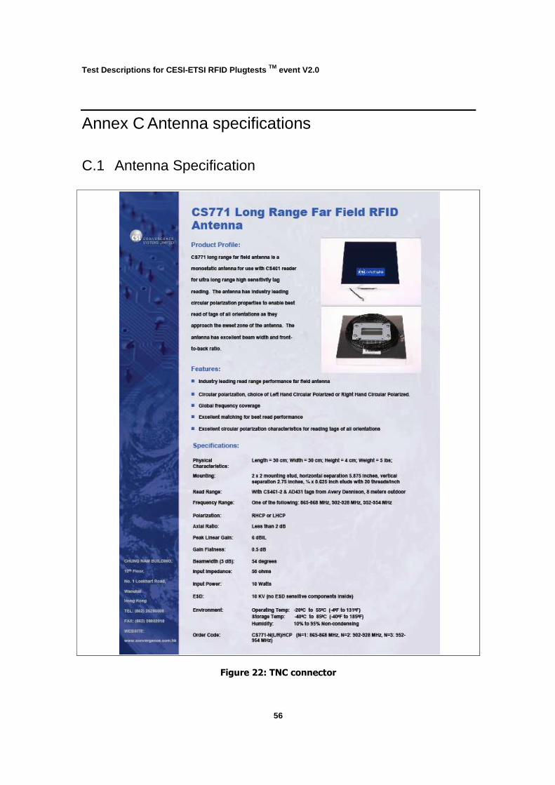
Test Descriptions for CESI-ETSI RFID Plugtests TM event V2.0
56
Annex C Antenna specifications
C.1 Antenna Specification
Figure 22: TNC connector
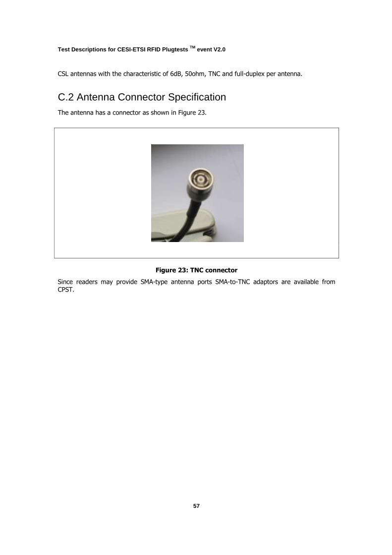
Test Descriptions for CESI-ETSI RFID Plugtests TM event V2.0
57
CSL antennas with the characteristic of 6dB, 50ohm, TNC and full-duplex per antenna.
C.2 Antenna Connector Specification The antenna has a connector as shown in Figure 23.
Figure 23: TNC connector
Since readers may provide SMA-type antenna ports SMA-to-TNC adaptors are available from
CPST.
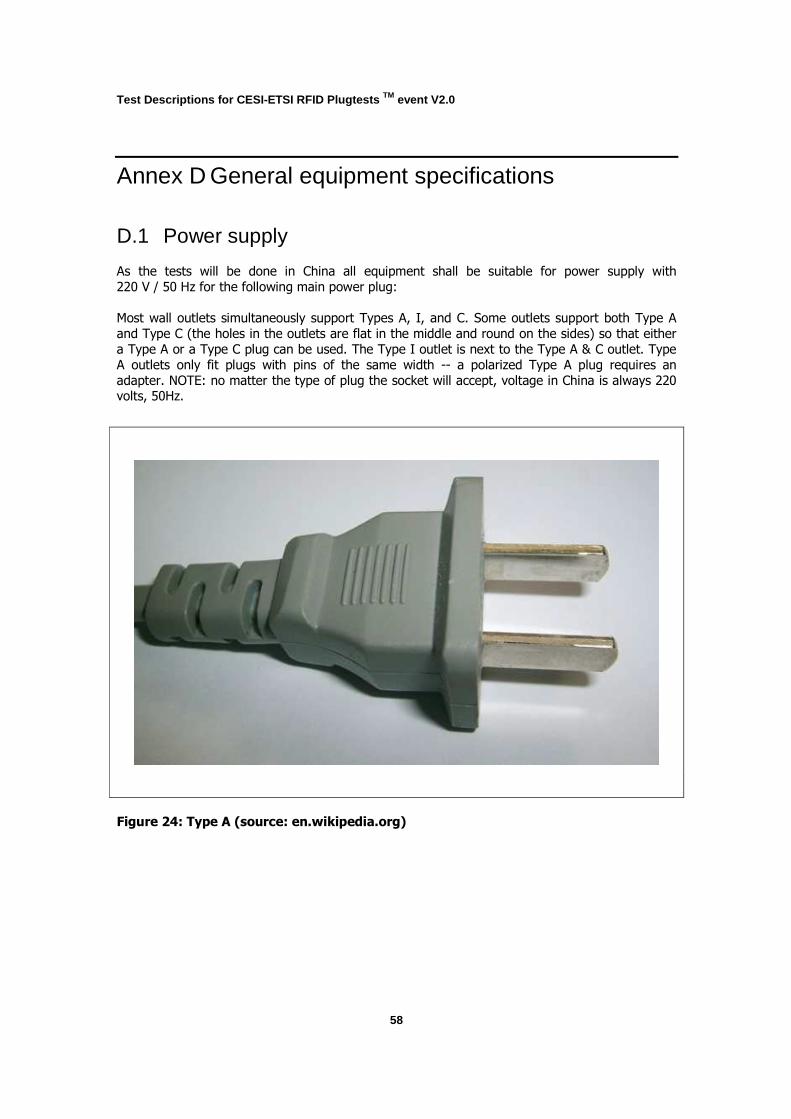
Test Descriptions for CESI-ETSI RFID Plugtests TM event V2.0
58
Annex D General equipment specifications
D.1 Power supply
As the tests will be done in China all equipment shall be suitable for power supply with
220 V / 50 Hz for the following main power plug:
Most wall outlets simultaneously support Types A, I, and C. Some outlets support both Type A
and Type C (the holes in the outlets are flat in the middle and round on the sides) so that either
a Type A or a Type C plug can be used. The Type I outlet is next to the Type A & C outlet. Type
A outlets only fit plugs with pins of the same width -- a polarized Type A plug requires an
adapter. NOTE: no matter the type of plug the socket will accept, voltage in China is always 220 volts, 50Hz.
Figure 24: Type A (source: en.wikipedia.org)
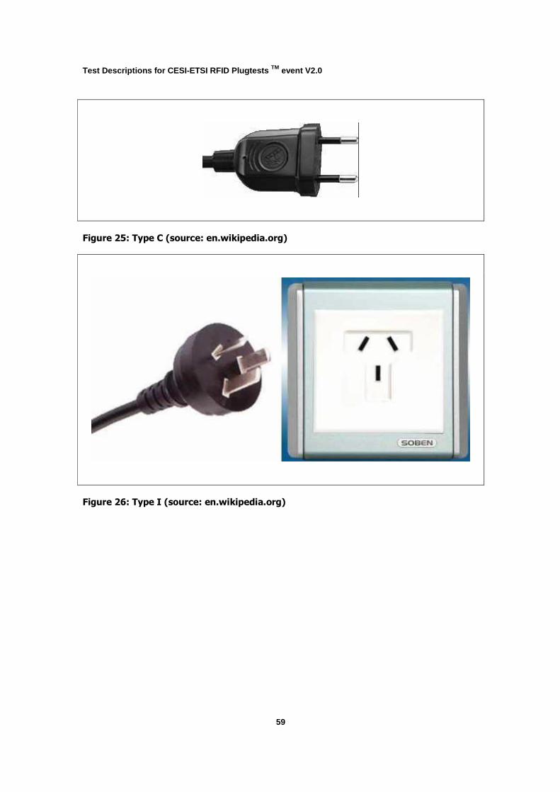
Test Descriptions for CESI-ETSI RFID Plugtests TM event V2.0
59
Figure 25: Type C (source: en.wikipedia.org)
Figure 26: Type I (source: en.wikipedia.org)

Test Descriptions for CESI-ETSI RFID Plugtests TM event V2.0
60
Annex E Spectrum Analyzer specification Tektronix RSA3408B
see http://www2.tek.com/cmsreplive/psrep/13400/37W_21129_1_2009.01.13.16.28.11_13400_EN.p
df
Test Descriptions for CESI-ETSI RFID Plugtests TM event V2.0
61
Annex F Tag Identifier Specification All tags are encoded with 96 bit identifiers.
The specification of these identifiers is as follows:
Country ID (24-bit) + Manufacture ID (24-bit) + Item class (24-bit) + Item serial number (24-
bit).
Country ID: 0086
Manufacture ID: 1,2,3,….
Item class:
1: mail container;
2: mail case;
3: mail bag.
Item serial number: unique number

Test Descriptions for CESI-ETSI RFID Plugtests TM event V2.0
62
References [1] ETSI EG 202 237; Generic approach to interoperability testing
[2] EPCglobal; EPC Radio-Frequency Identity Protocols; Class-1 Generation-2 UHF RFID; Protocol for Communications at 860 MHz - 960 MHz; Version 1.2.0
(http://www.epcglobalinc.org/standards/uhfc1g2/uhfc1g2_1_2_0-standard-20080511.pdf)
[3] ISO/IEC 18000-6 REV1 Information technology - Radio frequency identification for item
management – Part 6: Parameters for air interface communications at 860 MHz to 960
MHz
[4] ISO/IEC TR 18047-6; Information technology, automatic identification and data capture
techniques — RFID device conformance test methods — Part 6: Test methods for air interface communication at 860 - 960 MHz
[5] ETSI EN 302 208-1 V1.2.1: Electromagnetic compatibility and Radio spectrum Matters (ERM); Radio Frequency Identification Equipment operating in the band 865 MHz to 868 MHz with power levels up to 2 W; Part 1: Technical requirements and methods of measurement
[6] 800/900 MHz Radio Frequency Identification (RFID) Application Regulation (Temporarily) from State Radio Regulation Committee (SRRC), Ministry of Informatics Industry (MII), P.R.China
[7] http://www.etsi.org/plugtests/rfid2/RFID.htm
[8] ETSI TR 102 436 V1.2.1 Electromagnetic compatibility and Radio spectrum Matters (ERM); Short Range Devices (SRD) intended for operation in the band 865 MHz to 868 MHz; Guidelines for the installation and commissioning of Radio Frequency Identification (RFID) equipment at UHF
Test Descriptions for CESI-ETSI RFID Plugtests TM event V2.0
63
History REVISION DATE DESCRIPTION
0.1 2009/02/03 Initial draft based on received inputs 0.2 2009/02/06 Update based on received inputs 0.3 2009/02/09 Update based on received inputs 0.4 2009/02/11 Update based on received inputs 0.5 2009/02/16 Update based on received inputs 0.6 2009/02/16 Update based on received inputs 0.7 2009/02/20 Update based on received inputs and discussions 1.0 2009/03/03 First released version 1.1 2009/03/09 Update based on received inputs


![ETSI Plugtests Test Plan V1.0.0 (2017-02) · ... Architectural Framework". [NFV003] ETSI GS NFV 003: ... Interface and Information Model Specification". [IFA006] ETSI GS NFV-IFA 006:](https://static.fdocuments.in/doc/165x107/5b22cf767f8b9ac4748b456b/etsi-plugtests-test-plan-v100-2017-02-architectural-framework-nfv003.jpg)


![1st ETSI C-V2X Plugtests Report€¦ · references. [1] ETSI TS 103 301 V1.1.1 (2016-11): "Intelligent Transport Systems (ITS); Vehicular Communications; Basic Set of Applications;](https://static.fdocuments.in/doc/165x107/5f0c5ac57e708231d434fcd8/1st-etsi-c-v2x-plugtests-report-references-1-etsi-ts-103-301-v111-2016-11.jpg)


