
Test Benches - Milwaukee School of Engineering
27
Test Benches Last updated 1/19/21
Transcript of Test Benches - Milwaukee School of Engineering
Test Benches
Last updated 1/19/21

2 © tjCE 1911
Test Benches
These slides describe how to create testbench code
Upon completion: You should be able to write testbench code that allows visual verification of
circuit operation via waveforms

3 © tjCE 1911
Test Benches
• Testbench
• VHDL file used to run simulations on a block(s)
• Testbenches have:• One or more blocks instantiated in it
• Signals to drive the block’s inputs
• Signals to sense the block’s outputs
• Additional simulation related code• Generate input signals (with timing) to drive the block
• Note – this makes the testbench un-synthesizable

4 © tjCE 1911
Test Benches
• Testbench process
• Create simulatable VHDL files (testbench) to drive the inputs of our design• Note: these are not synthesizable
• Instantiate our design in the testbench file
• Simulate the design• ModelSim is our simulation tool
• View the resulting output waveforms and check for correctness

5 © tjCE 1911
Test Benches
• Create Design• Arbitrary logic example
• Set to top level, Elaborate and check for errors

6 © tjCE 1911
Test Benches
• Create component prototype• Rt-click the design file and select Create VHDL
Component… .cmp file created in the project directory Block_name.cmp→ component prototype

7 © tjCE 1911
Test Benches
• Create Testbench Code• Name your testbench the same as your design file but add _tb to the end
• counter_8bit.vhdl → counter_8bit_tb.vhdl
• shift_reg_nbit.vhdl→ shift_reg_nbit_tb.vhdl
• When we start using the DE10 we will do the same thing
• Name your DE10 implementation the same as your design file but add _de10 to the end
• counter_8bit.vhdl → counter_8bit_de10.vhdl
• shift_reg_nbit.vhdl→ shift_reg_nbit_de10.vhdl
• In both cases we never change the base design file• Ensures what we designed is what we simulate, and what we simulated is what we build
DesignFile
Testbench with Design File instantiated
DesignFile
DE10 with Design File instantiated
DesignFile
foo.vhdl
foo_tb.vhdl foo_de10.vhdl

8 © tjCE 1911
• Create Testbench Code• Description and entity
Test Benches
Description
Note – entity statement requirednothing in it
testbench name
9 © tjCE 1911
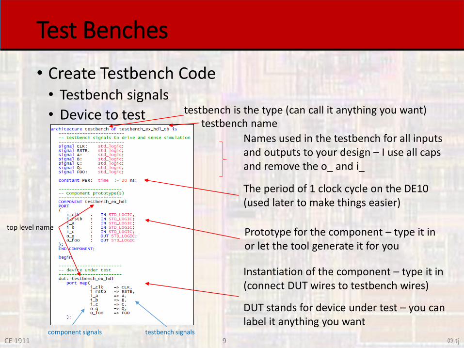
• Create Testbench Code• Testbench signals
• Device to test
Test Benches
testbench is the type (can call it anything you want)
Names used in the testbench for all inputsand outputs to your design – I use all capsand remove the o_ and i_
The period of 1 clock cycle on the DE10(used later to make things easier)
Prototype for the component – type it inor let the tool generate it for you
Instantiation of the component – type it in(connect DUT wires to testbench wires)
DUT stands for device under test – you canlabel it anything you want
component signals testbench signals
testbench name
top level name

10 © tjCE 1911
Test Benches
• Create Testbench Code• Test processes
Process for the clock signalRuns continuously
Process for the reset_bar signalRuns once then waits forever
Run process – cycles through a and cthen waits forever
Run process – cycles b and runs forever

11 © tjCE 1911
• Create Testbench Code• The wait command
Test Benches
wait for xx causes the process block
or construct to continue running(looping)
wait with no time causes the process
block or construct to remain in itscurrent state - signals no longer change

12 © tjCE 1911
Test Benches
• Quartus Interaction and ModelSim• Test benches can contain un-synthesizable code
• Quartus will generate errors on compilation if you set the testbench to the top level entity• Use the block under test as the top level entity

13 © tjCE 1911
Test Benches
• Elaborate your design• Run Analysis and Elaboration• Do not do a full compile, it is a waste of time
• Make sure your design (NOT the testbench) is selected as the top level block)
• Checks the design and testbench for errors (checks everything in the project)
• Creates the mathematical models of your design used in simulation

14 © tjCE 1911
Test Benches
• Prepare for simulation• Provides ModelSim with the required information to run
your testbench• Assignments → Settings → EDA Tool Settings → Simulation
Select Test Benches

15 © tjCE 1911
Test Benches
• Prepare for simulation• Provides ModelSim with the required information to run
your testbench
Select New

16 © tjCE 1911
• Prepare for simulation• Provides ModelSim with the required information to run
your testbench
Test Benches
Type in name of your testbench fileno .vhdl extension
Automatically filled in
Select End simulation at button Enter how long you want the simulation to run
Select …

17 © tjCE 1911
• Prepare for simulation• Provides ModelSim with the required information to run
your testbench
Test Benches
Select your testbench fileBe careful not to get the .bak version
Select Open

18 © tjCE 1911
• Prepare for simulation• Provides ModelSim with the required information to run
your testbench
Test Benches
Select Add

19 © tjCE 1911
• Prepare for simulation• Provides ModelSim with the required information to run
your testbench
Test Benches
Select OK
1
2
3
All available testbenches are hereSelect the one you want to run

20 © tjCE 1911
• Start ModelSim• Tools→ Run Simulation Tool → RTL Simulation
Test Benches

21 © tjCE 1911
Test Benches
• Start ModelSim• ModelSim will start in a new window• Often is starts minimized – so you need to select it from the toolbar

22 © tjCE 1911
• Simulation Results• Resize windows as desired
• Rt-click and select Zoom Full on the waveform window
Test Benches
Make sure you can seethe signal names

23 © tjCE 1911
Test Benches
• Simulation Results• Move around in the simulation window
zoom – scrollto desired sections of the simulation

24 © tjCE 1911
• Verify Design• Check critical sections to prove design works
• Document what you are showing
Test Benches
Reset – no changes
Q changingon clk edges
AC pattern stops
Make sure you can seethe signal names
A 0C 0
A 1C 0
A 0C 1
A 1C 1
FOO = A’B’
Q follows C’

25 © tjCE 1911
Test Benches
• Run Process Examples
Up/dn counter – DIR changes the direction
Enough clock cycles to make sure it wrapsthen - changes direction
Note: it then counts down forever

26 © tjCE 1911
Test Benches
• Run Process Examples
8 bit shift register (L/R based on DIR) (shift/no-shift based on SHIFT)
Initialize the input signals
Wait for reset to complete
No-shift
Shift 1 way – enough times to test all bits
Shift the other way – enough times to test all bits
No ‘wait’ at the end – repeats the whole process

27 © tjCE 1911
Test Benches
• Run Process Examples
Multiple RUN process – used for independent signals
Independent N/S signal
Independent E/W signal


![New Generation of Test Benches for Ultrasonic Testing of ... · automatic test benches is applied since more than a decade for periodic in-service inspection of solid axles [1]. These](https://static.fdocuments.in/doc/165x107/5e22779bf642bc5d7a201a79/new-generation-of-test-benches-for-ultrasonic-testing-of-automatic-test-benches.jpg)