
Test and Measurement - ARC Brasov. Masuratori de uz general... · earth testing Cable fault - test...
350
Test and Measurement Power Catalogue The word ‘Megger’ is a registered trademark Toil and trouble? Transformer oil tester selection made simple! The next steps in insulation diagnostics - details inside Getting down to earth - your complete guide to ground/ earth testing Cable fault - test vans, mobile and portable solutions
Transcript of Test and Measurement - ARC Brasov. Masuratori de uz general... · earth testing Cable fault - test...

Copyright © 2011 Megger Limited Archcliffe Road Dover CT17 9EN Part No. PCat_en_2013_V2
Pow
er Catalo
gu
e
Test and MeasurementPower Catalogue
The word ‘Megger’ is a registered trademark
Toil and trouble? Transformer oil tester selection made simple!
The next steps in insulation diagnostics - details inside
Getting down to earth - your complete guide to ground/earth testing
Cable fault - test vans, mobile and portable solutions
Local in more places.
Aargau, CH+41 62 768 20 30
Banuanch, DE+49 (0) 9544 68-0
College Station, TX USA+44 (0)1304 502100
Dover, UK+44 (0)1304 502100
Hong Kong, CN+852 2618 9964
Malaga, ES902 54 92 10
Radeburg, DE+49 (0) 35208 84 0
Trappes, FR01 30 16 08 90
Valley Forge, PA USA610-676 8500
Bloubergrant, SA+27 (021) 557 6572
Chonburi, TH+66 860103395
Dallas, TX USA1-800-723-2861
Dubai, AE+971 4 443 5489
Markham, CA1 416 298 6770
Oberursel, DE06171 92987 0
Sydney, AU+61 (0) 9397 5900
Taby, SE+46 8 510 195 00
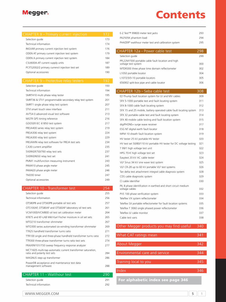
Contents 4
Getting the best from Megger 6
NEW products 8
Substation test equipment 10
CHAPTER 2a DC Insulation testers 12
` CHAPTER 2b AC Insulation testers 34
CHAPTER 3 - Low resistance ohmmeters 50
CHAPTER 4 - Power quality 80
CHAPTER 5 - Battery test 96
CHAPTER 6 - Circuit breaker test 120
CHAPTER 7 - Earth resistance testers 160
CHAPTER 8 - Primary current injection 172
CHAPTER 9 - Protective relay testers 192
CHAPTER 10 - Transformer test 254
CHAPTER 11 - Watthour test 290
CHAPTER 12a - Power cable test 298
CHAPTER 12b - Seba cable test 308
Other Megger products you may find useful 340
What CAT ratings mean 341
About Megger 342
Environmental care and service 344
Training local to you 345
Index 346

T: +44 (0) 1304 502100 E: [email protected]
Local in more places.Megger has technical support offices in over 30 locations, and distributors in 170 countries. Wherever possible, we
create documentation and websites that are centrally supported but locally maintained in your language. ‘Local’ to us
does not just mean geographic proximity; it is about understanding your technical problems, your application issues and
the language that you speak.
At Megger our goal is to provide you with a wide range of professional, reliable and safe test equipment that enables
you to carry out your job across a wide range of electrical assets and installations.
We do this through understanding both your business and test needs to ensure that we design and develop products,
services and training packages that support you in fulfilling the test and measurement role with an eye on accuracy,
speed and most importantly safety with out compromising on improving your productivity.
Everyone is driven by targets. Whether it is to minimise customer minutes lost outages or improve planning, Megger will
equip you with robust, reliable and easy to use test equipment. We also support you in enabling safe working practices
with well-designed and reliable test products that optimise safety in their usage; vital for safeguarding valuable
engineering staff.
At Megger we dedicate ourselves to improving electrical safety for our customers performing electrical tests throughout
our wide range of test and measurement equipment. I would urge you to take a closer look at how Megger can fulfil
your test and measurement needs with safety and reliability in mind!

WWW.MEGGER.COM 13

1 4 T: +44 (0) 1304 502100 E: [email protected]
Contents 4
Getting the best from Megger 6
NEW products 8
Substation test equipment 10
CHAPTER 2a DC Insulation testers 12 Selection guide 13
Technical information 14
MIT515 5 kV industrial insulation tester 17
MIT525 5 kV industrial insulation tester 18
MIT1025 10 kV industrial insulation tester 19
BM5200 5 kV insulation tester 20
S1-552/2 5 kV high current tester 21
S1-1052/2 10 kV high current tester 22
S1-554/2 5 kV tester with high noise rejection 23
S1-1054/2 10 kV tester with high noise rejection 24
S1-5010 diagnostic tester 25
MJ15 and BM15 5kV analogue insulation testers 26
5 kV and 15 kV megohmmeters 210400 and 210415 27
MIT30 30 kV high voltage tester 28
5 and 15 kV AC dielectric test set 29
70, 120, 160 kV high voltage DC dielectric test sets 30
Optional accessories 32
CHAPTER 2b AC Insulation testers 34 Selection guide 35
IDAX300 insulation diagnostic analyzer 36 CDAX605 High-precision capacitance and dissipation factor measurement instrument 38
DELTA4000 12 kV insulation diagnostic system 40
CB100 low voltage capacitance and insulation power factor test set 43
AC and AC/DC high pot tester 44
670025 series capacitance and dissipation factor test sets 46
Optional accessories 48
CHAPTER 3 - Low resistance ohmmeters 50 Selection guide 51
Technical information 52
DLRO200 200 A digital micro-ohmmeter 53
DLRO600 600 A micro-ohmmeter 54
DLRO10HD 10 A digital micro-ohmmeter 55
KC series wind turbine protection test leads 56
DLRO10 and DLRO10X digital micro-ohmmeter 57
BT51 low resistance ohmmeter 58
247000 series low resistance ohmmeter 59
MJÖLNER200 micro-ohmmeter 62
MJÖLNER600 micro-ohmmeter 64
MOM2 micro-ohmmeter 66
MOM200 A micro-ohmmeter 70
MOM600 A micro-ohmmeter 72
MOM690 micro-ohmmeter 74
Optional accessories 77
CHAPTER 4 - Power quality 80 Selection guide 81
Technical information 82
PA9Plus portable quality analyzer 84
PA9 Wireless portable quality analyzer 85
MDP series distribution profilers 88
MR-4 meter adapter recorders 90
SLM8 8 channel recording volt-ammeter 92
Power quality accessories 94
CHAPTER 5 - Battery test 96 Selection guide 97
Technical information 98
TORKEL820 battery load unit 101
TORKEL840/860 battery load units 104
BVM battery voltage monitor 108
BGFT battery ground fault locator 110
BITE2 and BITE2P battery impedance testers 111
BITE3 battery impedance tester 113
PowerDB battery database management software 115
BITE optional accessories 116
TORKEL optional accessories 118
CHAPTER 6 - Circuit breaker test 120 Selection guide 121
Technical information 122
CabaWin circuit breaker analysis software 124
EGIL circuit breaker analyzer 125
TM1700 circuit breaker analyzer system 128
TM1800 circuit breaker analyzer system 136
SDRM202 static/dynamic resistance measurement 143
VIDAR vacuum interrupter tester 145
B10E AC/DC voltage power supply 148
MS-2A circuit breaker and overcurrent relay test set 150
OCR-8015 and OCR-9150 automatic oil circuit recloser test set 152
Optional accessories 155
CHAPTER 7 - Earth resistance testers 160 Selection guide 161
Technical information 162
DET3TD 2 and 3 pole tester 164
DET3TC ART enabled 2 and 3 pole tester 165
DET4TC2 and DET4TCR2 2,3 and 4 pole tester (stakeless + ART) 166
DET4TD2 and DET4TR2 2, 3 and 4 pole tester 167
DET14C and DET24C earth resistance clamp testers 168
DET2/2 auto earth tester 169
Ground testing methods chart 170
Optional accessories 171
Contents
5 1WWW.MEGGER.COM
CHAPTER 8 - Primary current injection 172 Selection guide 173
Technical information 174
INGVAR primary current injection test system 176
ODEN AT primary current injection test system 179
ODEN A primary current injection test system 184
CSU600A-AT current supply units 187
PCITS2002/2 primary currenct injection test set 189
Optional accessories 190
CHAPTER 9 - Protective relay testers 192 Selection guide 193
Technical information 194
SMRT410 multi phase relay tester 195
SMRT36 & STV1 programmable secondary relay test system 201
SMRT1 single phase relay test system 207
STVI smart touch view interface 211
AVTS4.0 advanced visual test software 213
MGTR GPS timing reference 216
GOOSER IEC 61850 test system 217
FREJA400 series relay test system 219
FREJA306 relay test system 224
FREJA300 relay test system 229
FREJAWIN relay test software for FREJA test sets 234
CA30 current amplifier 235
SVERKER750/760 relay test sets 237
SVERKER650 relay test set 241
PMM1 multifunction measuring instrument 243
PAM410 phase angle meter 245
PAM420 phase angle meter 246
TM200 timer 247
Optional accessories 249
CHAPTER 10 - Transformer test 254 Selection guide 255
Technical information 256
OTS80PB and OTS60PB portable oil test sets 257
OTS100AF, OTS80AF and OTS60AF laboratory oil test sets 261
VCM100D/VCM80D oil test set calibration meter 264
KF875 and KF-LAB MkII Karl Fischer moisture in oil set sets 265
MTO210 transformer ohmmeter 267
MTO300 series automated six-winding transformer ohmmeter 269
TTR25 handheld transformer turns ratio 271
TTR100 single and three-phase handheld transformer turns ratio 272
TTR300 three-phase transformer turns ratio test sets 274
FRAX99/101/150 sweep frequency response analyzer 277
MCT1605 multi-tap automatic current transformer saturation, ratio and polarity test sets 284
MAGNUS step-up transformer 286
PowerDB acceptance and maintenance test data management software 288
CHAPTER 11 - Watthour test 290 Selection guide 291
Technical information 292
Contents E-Z Test™ 99800 meter test jacks 293
PA2505K phantom load 294
PHAZER® watthour meter test and calibration system 295
CHAPTER 12a - Power cable test 298 Selection guide 299
PFL22M1500 portable cable fault location and high voltage test system 300
MTDR300 three phase time domain reflectometer 302
L1050 portable locator 304
L1072/3/3-10 portable locators 305
656902 split-box pipe and cable locator 306
CHAPTER 12b - Seba cable test 308 EZ-Thump fault location system for LV and MV cables 309
SFX 5-1000 portable test and fault locating system 311
SFX 8-1000 cable fault locating system 312
SFX 15 and 25 mobile, battery operated cable fault locating system 313
SFX 32 portable cable test and fault locating system 314
SFX 40 mobile cable testing and fault location system 315
digiPHONE+ surge wave receiver 317
ESG NT digital earth fault locator 318
MFM 10 sheath fault location system 319
HV tester 25 kV portable HV tester 320
HV test set 50/80/110 kV portable HV tester for DC voltage testing 321
T 99/1 high voltage test unit 322
HPG 70-K high voltage test set 323
Easytest 20 kV AC cable tester 324
VLF Sinus 34 kV sine wave test system 325
VLF CR-28 up to 60 kV portable VLF test systems 326
Tan delta test attachment integral cable diagnosis system 328
CDS cable diagnostic system 329
CI cable identifier 330
PIL 8 phase identifcation in earthed and short circuit medium voltage cables 332 PVS 100 phase verification system 333 Teleflex VX system reflectometer 334 Teleflex SX portable reflectometer for fault location systems 335
Teleflex T 3060 single phased power reflectometer 336
Teleflex LV cable monitor 337
Cable test vans 338
Other Megger products you may find useful 340
What CAT ratings mean 341
About Megger 342
Environmental care and service 344
Training local to you 345
Index 346
For alphabetic index see page 346

1 6 T: +44 (0) 1304 502100 E: [email protected]
Getting the best from Megger
Technical support group
T: 01304 502102E: [email protected] team is here to help you with your questions. Trained to provide support for Megger’s complete range of products, the technical support group helps with everything from advice on product selection to product usage.
Professional trainingYou can count on Megger to provide specialised practical, hands-on electrical training presented in our classrooms or on-site at your facility. Through our associated company, AVO Training, we also provide online fundamental training courses, self-study training materials, and training videos. Select from more than 50 different electrical training courses.
Technical distribution networkMegger regularly audits the performance of distribution partners to ensure they meet standards for technical proficiency and customer support. You can trust an authorised Megger distributor to help you choose the right test equipment.
A passion for the business of test and measurementOver 100 years ago – in 1885 to be precise – Sydney Evershed launched a product that was to change the course of history. He applied a current to a stationery coil to cause a piece of soft iron to move in the magnetic field created by the coil. He had just made the first moving iron electrical measuring instrument. 10 years later, he and Ernest Vignoles purchased the instrument section of Goolden and Trotter where they worked, and created Evershed and Vignoles in London, England. They registered the Megger trademark in 1903 and launched the first insulation tester in 1905. The earliest Megger insulation testers had two massive bar magnets with pole pieces at both ends, so that
one end did for the moving coils and the other provided the generator field. After more than 100 years of research and having opened customer support sites close to the industrial hubs around the world, you can now get access to the world’s widest range of electrical test and measurement equipment available anywhere.
If you’re ready to equip your professional life with the latest Megger test and measurement technology, we urge you to contact us today.

7 1WWW.MEGGER.COM
Our commitment to quality
All Megger manufacturing facilities are certified to the ISO9001 quality standard. Products conform to the highest standards of accuracy, safety, performance and reliability and meet national and international safety directives. Our commitment to quality is recognised by our customers throughout the world.
The letters “CE” are an abbreviation of the French phrase “Conformité Européene” which literately means “European Conformity”. CE Marking on a product indicates that the product may be legally placed on the market in a European Union country.
cUnderwriters Laboratories® is a US based independent product safety certification organization. The UL Mark on a product means that UL has tested and evaluated representative samples of that product and determined that they meet UL requirements.
Based in Canada, CSA International tests products for compliance to national and international standards. A CSA mark on its own, without indicators, means that the product is certified primarily for the Canadian market, to the applicable Canadian standards.
TÜV is a German organisation that aims to achieve sustained development of safety and quality. The TÜV mark gives evidence that the essential safety requirements of the product have been fulfilled and that production has been inspected by the impartial organisation TÜV Rheinland Product Safety.
The VDE mark indicates conformity with the VDE standards or European or internationally harmonized standards respectively and confirms compliance with protective requirements of the applicable EC Directive(s).
GOST refers to a set of technical standards maintained under the auspices of the Commonwealth of Independent States. Certification is mandatory for a wide range of products. It is based on safety testing (IEC standards with Russian variations), EMC testing, etc.
Any electrical, mechanical or electro-mechanical product bearing the GS Mark indicates that it was tested and complies with the minimum requirements of the German Equipment and Product Safety Act. The GS Mark, which stands for Geprüfte Sicherheit in German means Safety Tested.
The Kitemark is one of the UK’s most trusted product and service certification marks. Products showing this mark have satisfied the most rigorous of quality processes.
You may see these symbols marked on our products:
Electrical TesterA newspaper primarily aimed at the Power/Utility industry, Electrical Tester contains informative articles on the latest industry developments and products from Megger. The publication is published in many languages and is available in both print and email formats. To subscribe to Electrical Tester, email [email protected] with your contact details specifying which version you would like to receive.
ExhibitionsYou will find Megger at many major exhibitions where you can talk to Megger experts and see the products before you buy. Check your regional Megger website for an exhibition convenient for you.
www.megger.comFor more in-depth information on Megger products and application advice visit our website. With improved navigation, it is easier than ever to search for the information you need.
1
www.megger.com
Megger ELECTRICAL TESTER October 2011
ELECTRICAL
TESTER The industry’s recognised information tool
Published by Megger
October 2011
The road to
uncertainty in
stand-by power
systems
Georg Halfar
Marketing Communications Manager,
Megger Germany
Alienpart 2!see page 7
It’s a drag!
see page 6
The year of the
Rabbit
see page 8
The sixth Megger Battery Conference, which
was recently held in Brilon in Sauerland in
Germany, was devoted to considering the
future of standby power supplies, particularly
in relation to the changes that are taking place
in energy supply networks.
Clear movement is already apparent toward
decentralised energy supply networks with
increasing numbers of connection points
for renewable energy sources, and the recent
events in Japan will only accelerate this
movement. In short, the ecological transformation
of national and international energy supply
systems has started, and this has profound
implications for standby power systems.
Today’s energy supply networks are still
mainly fed by large central power stations but,
in the future, small energy sources, based on
wind, solar or other renewable technologies,
will play a much greater role. The energy
available from these sources can however,
continued on page 2
Low resistance ohmmeters are amazingly
useful instruments, with applications that range
from checking the condition of the resistance
of circuit breaker contacts to confirming the
integrity of welds in racing car safety cages.
If they are to give reliable and meaningful
results, however, and in some cases to ensure
compliance with applicable standards, these
instruments have to carry out tests at high
currents – typically 100 A or more.
Therein lies a problem. A low resistance
ohmmeter capable of delivering this much
current is unavoidably heavy, bulky and
expensive. That’s not really ideal when tests
have to be carried out in locations that are hard
to access, such as underground substations,
deep within the bowels of a racing car, ae
ro-
plane maintenance or working at height. And
there’s yet another issue – these instruments are
necessarily mains powered, and there are many
sites where arranging for a suitable supply is by
no means easy.
But what’s the alternative? Until recently there
wasn’t one, but in the last few months a new
breed of digital low resistance ohmmeters has
appeared, and these new instruments seemingly
do the impossible.
They’re small, handheld units that weigh only
around 1 kg – that’s around one-twentieth of
the weight of a conventional high current low
resistance ohmmeter – and they are, compared
with their conventional counterparts, almost
unbelievably inexpensive. In spite of their
diminutive size, weight and price, these ground-
breaking instruments can measure resistance at
currents in excess of 200 A.
The benefits are easy to appreciate – we’re
essentially talking about go-anywhere low
resistance testers that are as convenient to
handle and use as a multimeter. But how
is it possible to get so much current out of
such a small package? The answer is to use
an ultra capacitor. In almost every way, these
novel components are much the same as
ordinary capacitors and just about the same
size, but there’s one big difference. They have
capacitance values measured in hundreds of
farads rather than microfarads.
In outline, this is how one of the new generation
low resistance ohmmeters works: first it charges
the ultra capacitor then, to carry out the test,
it discharges it through the test object while
measuring current and voltage. The instrument
uses these values to calculate the resistance of
the test object. Since the ultra capacitor has a
very high capacitance value, it can store enough
energy to deliver a hundred amps or more for
an appreciable length of time – certainly long
enough for accurate and dependable results to
be obtained.
Testing with my MOM!Nils Wäcklén
Product Manager
Of course, there’s a littl
e bit more than this
involved in producing a practical instrument, but
the principle is clear. In addition, it’s not difficult
to see that an instrument of this type can be
designed to work from batteries, which would
charge the ultra capacitor thereby eliminating the
need for a mains supply.
To provide an idea of what can be expected from
these new handheld low resistance ohmmeters,
the patent pending Megger MOM2 can deliver
an initial test current of up to 220 A, and a
guaranteed minimum current of 100 A for three
seconds for each measure, which easily meets the
requirements of both the IEC and IEEE standards
for measuring contact resistance in high- and
medium-voltage circuit breakers.
It has a measuring range of 1 µΩ to 1 Ω, with
a resolution down to 1 µΩ, depending on the
range, and it features rechargeable batteries with
sufficient capacity to handle a full day of testing.
It is only to be expected that, in spite of the
convenience of these new instruments, some
users will have reservations about using them
because they are used to working with traditional
instruments that can deliver current continuously.
In most cases however, this is not a real concern.
We have already noted that the new instruments
fully meet international standards for checking
circuit breaker contacts and, in other applications,
like measuring the resistance of busbar joints
or welds, the duration of the current flow is
unimportant, provided that it is long enough to
allow accurate results to be acquired.
In some cases a slight modification of working
practice might be needed. For example, in the
past it might have been the usual practice to
inject a continuous current into a whole section
of busbar and then measure the voltage drop
across each joint with either the ohmmeter test
leads or a voltmeter. Given the very portable
nature of the new instruments, however, and
their ease of use, an equally valid and convenient
approach is to measure the resistance of each
joint individually.
Only in a very few cases is the use of continuous
test current essential, such as when it is necessary
for the object under test to be heated by the
passage of current over a period of time. In
these cases, the new handheld low resistance
ohmmeters are clearly not the right tool for the
job, but it is worth reiterating that these situations
are few and far between.
Lugging heavy test equipment around is never
a pleasure and there are many instances where
the use of bulky mains powered equipment is
difficult if not impossible. The new handheld
low-resistance ohmmeters provide a genuine
and genuinely convenient alternative not only
in these instances but in almost every situation
where low resistance needs to be measured
accurately with high test currents.
1
www.megger.com
Megger ELECTRICAL TESTER January 2013
ELECTRICALTESTER The industry’s recognised information tool
Published by Megger January 2013
A HELPING HAND AFTER THE HURRICANE
Product development - how hard can it be?
see page 2
In October 2012, when the extent of the
damage and disruption caused by Hurricane
Sandy became apparent, public-spirited
companies both in the United States and from
around the world were quick to respond in
an urgent attempt to restore electrical power
and bring water damaged electrical assets back
into service.
One of the first organizations hit by the violent
storm was the Linden Co-Generation Plant,
which is operated by GE Energy and supplies
power to Conoco Phillips petroleum processing
plant in Linden, NJ. This plant had been hit by
a two metre (six foot) wall of water, and was
so badly affected that at one stage, its employees
had to evacuate to the rooftop due to a fire in
the electrical room caused by the storm surge
which made its way several kilometres inland.Just before the hurricane, GE Energy had taken
delivery of two new Megger instruments – a
SMRT36 Relay Test Set and a DELTA4000 12 kV
insulation diagnostic system for testing protective
relays and protection systems. Staff knew that
both instruments would be invaluable tools
for helping them to get their plant back into
service, but they needed training on how to
use them.
Ron Quade, Megger’s sales engineer for New
Jersey was on the spot. His home is in Morris
County, New Jersey, an area that was badly
affected by the hurricane and subsequently
declared a disaster area. He was able to make
his way to the GE plant and provide the
training needed for the staff to make best use
of their new instruments. When the next call for help came however,
Ron could no longer get fuel for his car. Longo,
a leading electrical-mechanical sales and
service company, had to come to his home
to pick up the instruments they needed – a
Torkel battery load unit and a BITE2P
battery impedance test set. These were
urgently required to help restore production at
Pratt Industries, America’s fifth largest box
manufacturer, where a large battery back-up
installation had been damaged by floodwater.PSE&G, a public utility that supplies electricity
and gas throughout much of New Jersey
also benefited from the free loan of test
equipment. PSE&G borrowed a DLRO200
low-resistance ohmmeter and an S1 552 5 kV
insulation tester, both of which were used to
help verify the safe operation of plant apparatus
and devices before they were returned to
service. Five of PSE&G’s power plants tripped
offline due to flooding caused by the
tremendous storm surge.Atlantic City Electric, a utility that supplies
electricity to 547,000 customers in New Jersey,
faced a different challenge. Because of the
damage and flooding caused by Hurricane
Sandy it had been forced to cut services to
220,000 of those customers, as this was the
only fast and safe way to ensure that no wet
and flooded installations were energized. Many of the disconnected customers, how-
ever, had installations that were neither wet
nor flooded and the top priority for Atlantic
City Electric was to restore service to these
while ensuring that unsafe installations
remained de-energized. Made aware of this
need, Derrick Smith, one of Megger’s area
managers for cable fault location testing
and diagnostics, were able to offer a solution
by lending a SebaKMT CI universal cable
identification unit to engineers at Atlantic City
Electric.
Designed to make it easy to positively identify
individual power cables, the CI cable identifier
helped the engineers determine which of its
cables were supplying homes with safe electrical
installations and which were supplying homes
with damaged and potentially unsafe equipment.
This made it possible to restore service quickly
to customers with safe installations, while safe-
guarding the others.The impact of Hurricane Sandy was devastating
and in many cases, made it difficult for
companies to respond – even Megger’s
Horace A DavisVP Sales, North America
manufacturing plant in Pennsylvania was
temporarily closed as a result of the storm.
Fortunately global companies like Megger
were in a good position to help, as they could
call on resources and supplies from their global
distribution networks and Megger was able to
air freight large quantities of test equipment
from its UK manufacturing facility.In the end, it was individuals who made the
difference.
People like Shane McIntosh in Dover, Kent
who worked long hours to pack instruments
Forgotten geniuses see page 8
Bird on a wireSee page 8
THE (FREE) CHARGE OF THE LIGHT BRIGADE
These days almost every type of portable
electronic equipment, from insulation testers
to mobile phones, seems to at least have an
option to be powered by rechargeable
batteries. And the chargers for those batteries
seem to get smaller by the year. This is not
just a modern phenomenon, however. In the
1920s, rechargeable batteries were already in
widespread use and for many users the size
of the chargers wasn’t an issue, as they didn’t
need one!
Rechargeable batteries, which were usually
referred to at the time as accumulators, were
commonly used from the 1920s right through
into the 1950s to provide the low-voltage
supply needed for valve (vacuum tube)
radios. Many garages of the era ran an
accumulator charging service as a profitable
sideline, but the truly thrifty charged their own
accumulators at home, almost for free.They could do this because, at that time,
many homes had dc mains supplies. The
technique for charging an accumulator from
a dc supply was very simple – just connect
it in series with your home lighting circuit.
The two volts dropped across the accumulator
made virtually no difference to the brightness
of the bulbs – domestic dc supply voltages
were typically in the range 100 V to 200 V –
and you could conveniently (?) regulate the
charging current by turning lights on and off.
There you have it. Charging for free and no
charger needed!There were a few small practical points,
however, the first being how to connect into
the lighting circuit. The favourite method
seems to have been to remove a fuse from
the fuseboard (the latterday equivalent of a
consumer unit) and connect the accumulator
in its place. This was easy to do, as the fuses
in those days were often rewirable types. continued on page 8
for shipment to the northeastern United States,
as well as Ron Quade and Derrick Smith in
the USA who were literally prepared to go the
extra mile to support recovery efforts.
Ian BenstedApplication Engineer

1 8 T: +44 (0) 1304 502100 E: [email protected]
NEW products
Relay tester (Freja series)
The FREJA 400-series is a new member of the relay testing equipment from Megger, quick and easy to use. The rugged hardware design is built for field use over a wide temperature range, with the possibilities of intelligent software to perform rapid testing. See page 219
Earth / ground resistance clamp testers (DET14C and DET24C)
DET14C and DET24C represent a new generation of earth / ground testers. They are designed with flat core ends that prevent dirt build up and an elliptical clamp to improve access to earth cables and straps. See page 168
Multi phase relay tester (SMRT410)
The SMRT410 provides muti-phase testing flexibility with modules providing high power capability to both voltage and current channels. See page 195
Micro-ohmmeter for circuit breaker testing (MOM2)
MOM2 is designed to measure the resistance of circuit breaker contacts, bus-bar joints and other high-current links. This product is designed to be easy to use, versatile and safe, using the DualGround™ method (the test object is grounded on both sides). See page 66
Oil test sets (OTS)
Equally at home in the laboratory, the workshop, in the field, on the bench or on the ground. These new heavy duty OTS oil test sets combine rugged construction with accuracy and ease of use. Includes bright 3 1/2 inch colour display for easy visibility. See page 258
Sheath fault location system (MFM 10)
The intuitive menu-driven operation of the MFM 10 with fully automatic measurement and evaluation enables the testing of cable sheaths as well as the pre-location and pinpointing of cable sheath faults in the most simple way possible. See page 331
Surge wave receiver for accoustic/electro-magnetic pinpointing (digiPHONE+)
The intuitive menu-driven operation of the MFM 10 with fully automatic measurement and evaluation enables the testing of cable sheaths as well as the pre-location and pinpointing of cable sheath faults in the most simple way possible. See page 316
Cable fault locating system (SFX 8-1000)
The intuitive menu-driven operation of the MFM 10 with fully automatic measurement and evaluation enables the testing of cable sheaths as well as the pre-location and pinpointing of cable sheath faults in the most simple way possible. See page 311

9 1WWW.MEGGER.COM
NEW products
Power factor / dissipation factor test set (DELTA4000)
DELTA4000 is a fully automatic 12 kV insulation power factor / dissipation factor (tan∂) test set designed for condition assessment of electrical insulation in high voltage apparatus such as transformers, bushings, circuit breakers, cables, lightning arresters and rotating machinery. See page 40
5 & 10 kV DC Insulation resistance testers
The new range of industrial insulation resistance testers (IRTs) are smaller and lighter than previous models yet offer advanced features and rapid charge capability. The range consists of three models; an entry level 5 kV and two fully featured units, one 5 kV the other 10 kV. Resistance measurement up to 10 TΩ for the 5 kV models and 20 TΩ for the 10 kV model. See page 17
Capacitance and dissipation factor test set (CDAX 605)
CDAX 605 is a capacitance and dissipation factor test set to be used with an external power source/generator. It is a precision instrument using a combination of bridge and direct (vector) measurements and is capable of measuring capacitive, resistive and inductive loads. See page 38
Mobile cable testing and fault location system (SFX 40)
The SFX 40 is a mobile, multi-functional system for testing, converting, prelocation and pinpointing cable faults in low and medium voltage networks.See page 33
Sine wave test system (VLF Sinus 34 kV)
The VLF sine wave 34 kV is a compact, robust and portable VLF sine wave test system for medium voltage cables. The VLF testing system is easy to use, thanks to its single button operation and clear, simply structured menu and colour display. See page 323
Circuit breaker analyzer (TM1700)
The TM1700 series circuit breaker analyzers utilizes some of the ground breaking technology from the top of the line version TM1800. There are four models starting from PC-remote controlled to fully stand-alone. All models can be controlled from a computer using the well proven data management and analyzing software CABA Win. See page 128
Single phase relay test system (SMRT1)
As a stand-alone unit the SMRT1 has the “smart” combination of high compliance voltage andhigh current to test electro-mechanical, solid-state an micro-processor-based overcurrent relays. See page 207
Battery voltage monitor (BVM)
The Megger BVM is a battery voltage measurement device thatis used for the capacity testing of large, industrial battery bankscommonly found in electrical power sub-stations, telecom facilities and computer data center UPS systems. See page 128

1 10 T: +44 (0) 1304 502100 E: [email protected]
Substation test equipment
Circuit breaker testingVIDAR - Vacuum bottle breakdown tester
TM1800 - Modular timing and motion analyser for multiple break /phase circuit breakers with DualGround™ for operation with both sides of the test piece earthed. 40 kHz sample rate, on-board software, key board, colour display
TM1700 - Diverse models, full stand-alone functionality or data acquisition models without user interface
SDRM – Current source for static / dynamic resistance measurement of arcing and main contacts while the circuit breaker operates for use with TM and EGIL products
EGIL - Timing and motion analyser for single break /phase circuit breakers
B10E – Variable d.c. power supply
CABA Win – Circuit breaker analysis software
MJÖLNER – High current testing for circuit breaker contact resistance 200 A and 600 A with DualGround™ for operation with both sides of the test piece earthed
DLRO600 and DLRO200 – High current micro ohmmeters for testing circuit breaker contacts at 600 A and 200 A for compliance with IEC 62271-100
MOM690, MOM600 and MOM200 – High current low resistance ohmmeter for testing circuit breaker contacts at 690 A, 600 A and 200 A for compliance with IEC 62271-100
MOM2 – Micro-ohmmeter designed to deliver up to 240 A and measure the resistance of circuit breaker contacts, bus-bar joints, and other high-current links.
DLRO10HD, DLRO10 and DLRO10X – 10 A battery powered low resistance ohmmeter for testing contact resistance and joints
Insulation and continuity test instrumentsMIT515 – 5 kV industrial insulation resistance tester
MIT525 – 5 kV industrial insulation resistance tester
MIT1025– 10 kV industrial insulation resistance tester
S1-552/2 and S1-1052 - High current diagnostic utility insulation testers for fast testing of capacitive loads
S1-554/2 and S1-1054/2 - 5 kV and 10 kV utility diagnostic insulation testers with extra high noise rejection for environments such as switch yards
DLRO10HD, DLRO10 and DLRO10X - fully automatic
instruments, selecting the most suitable test current up to 10 A d.c.
MIT30 – 30 kV d.c. insulation tester for proof testing
70 to 160 kV d.c dielectric test sets – insulation proof testing
11 1WWW.MEGGER.COM
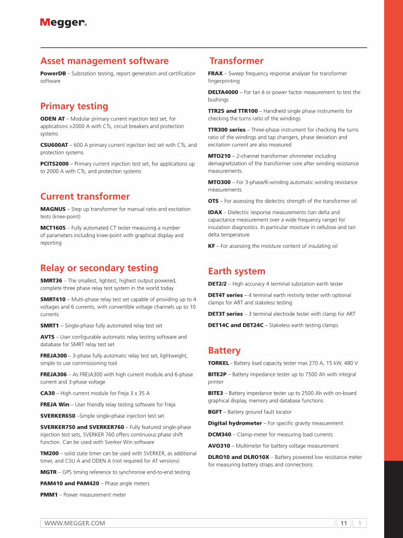
Asset management softwarePowerDB – Substation testing, report generation and certification software
Primary testingODEN AT – Modular primary current injection test set, for applications >2000 A with CTs, circuit breakers and protection systems
CSU600AT – 600 A primary current injection test set with CTs, and protection systems
PCITS2000 – Primary current injection test set, for applications up to 2000 A with CTs, and protection systems
Current transformerMAGNUS – Step up transformer for manual ratio and excitation tests (knee-point)
MCT1605 – Fully automated CT tester measuring a number of parameters including knee-point with graphical display and reporting
Relay or secondary testingSMRT36 – The smallest, lightest, highest output powered, complete three phase relay test system in the world today
SMRT410 – Multi-phase relay test set capable of providing up to 4 voltages and 6 currents, with convertible voltage channels up to 10 currents
SMRT1 – Single-phase fully automated relay test set
AVTS – User configurable automatic relay testing software and database for SMRT relay test set
FREJA300 – 3-phase fully automatic relay test set, lightweight, simple to use commissioning tool
FREJA306 – As FREJA300 with high current module and 6-phase current and 3-phase voltage
CA30 – High current module for Freja 3 x 35 A
FREJA Win – User friendly relay testing software for Freja
SVERKER650 –Simple single-phase injection test set
SVERKER750 and SVERKER760 – Fully featured single-phase injection test sets, SVERKER 760 offers continuous phase shift function. Can be used with Sverker Win software
TM200 – solid state timer can be used with SVERKER, as additional timer, and CSU A and ODEN A (not required for AT versions)
MGTR – GPS timing reference to synchronise end-to-end testing
PAM410 and PAM420 – Phase angle meters
PMM1 – Power measurement meter
TransformerFRAX – Sweep frequency response analyser for transformer fingerprinting
DELTA4000 – For tan δ or power factor measurement to test the bushings
TTR25 and TTR100 – Handheld single phase instruments for checking the turns ratio of the windings
TTR300 series – Three-phase instrument for checking the turns ratio of the windings and tap changers, phase deviation and excitation current are also measured
MTO210 – 2-channel transformer ohmmeter including demagnetization of the transformer core after winding resistance measurements
MTO300 – For 3-phase/6-winding automatic winding resistance measurements
OTS – For assessing the dielectric strength of the transformer oil
IDAX – Dielectric response measurements (tan delta and capacitance measurement over a wide frequency range) for insulation diagnostics. In particular moisture in cellulose and tan delta temperature
KF – For assessing the moisture content of insulating oil
Earth systemDET2/2 – High accuracy 4 terminal substation earth tester
DET4T series – 4 terminal earth restivity tester with optional clamps for ART and stakeless testing
DET3T series – 3 terminal electrode tester with clamp for ART
DET14C and DET24C – Stakeless earth testing clamps
BatteryTORKEL - Battery load capacity tester max 270 A, 15 kW, 480 V
BITE2P – Battery impedance tester up to 7500 Ah with integral printer
BITE3 – Battery impedance tester up to 2500 Ah with on-board graphical display, memory and database functions
BGFT – Battery ground fault locator
Digital hydrometer – For specific gravity measurement
DCM340 – Clamp-meter for measuring load currents
AVO310 – Multimeter for battery voltage measurement
DLRO10 and DLRO10X – Battery powered low resistance meter for measuring battery straps and connections

2 12 T: +44 (0) 1304 502100 E: [email protected]
Selection guide ........................................................................................... 13Technical information .................................................................................. 14MIT515 5 kV industrial tester ...................................................................... 17MIT525 5 kV industrial tester ...................................................................... 18MIT1025 10 kV industrial tester .................................................................. 19BM5200 insulation tester ............................................................................ 20S1-552/2 5 kV high current utility tester ...................................................... 21S1-1052/2 10 kV high current utility tester .................................................. 22S1-554/2 5 kV utility tester with noise rejection ........................................... 23S1-1054/2 10 kV utility tester with noise rejection ....................................... 24S1-5010 10 kV utility diagnostic tester ........................................................ 25MJ15 and BM15 5 kV analogue insulation testers ....................................... 265 and 15 kV megohmmeters 210400 and 210415 ...................................... 27MIT30 30 kV high voltage tester ................................................................. 285 and 10 kV dielectric test sets .................................................................... 2970, 120, 160 kV high voltage DC dielectric test sets .................................... 30Optional accessories .................................................................................... 32Chapter 2b AC insulation testers ................................................................. 34
2a
Regular insulation resistance testing is one of the most cost effective methods of identifying ageing in electrical equipment, and with over 60% of equipment failures being ascribed to insulation breakdown, it is a key area to monitor for high levels of customer satisfaction.
DC Insulation Testers

13 2WWW.mEggEr.com
General purpose
Utility range
SELECTION GUIDE
n feature £ option
MIT200 Seies
MIT300 Seires
MIT400 Seires
MIT515
MIT525
MIT1025
BM12/M
J10
S1-552/2
S1-1052/2
S1-554/2
S1-1054/2
S1-5010
BM15
MJ15
5 kV and 15 kV
5 kV and 10 kV
BM5200 not
CE m
arked
70, 120, 160 kV
MIT30 kV
insulation test voltages n n n
User selectable test voltage n n
10 kV n n n
5 kV n n n n n n n n n n n n n n
2.5 kV n n n n n n n n n n n n n n
1000 V £ £ n n n n n n n n n n n n n n n n
500 V n n n n n n n n n n n n n n n n n n
250 V n n n n n n n n n n n n n n n
50 V/100 V n n n n n n n
10 V - 100 V n n n n n
VL n n n n n
insulation test modes
Polarization index n n n n n n n n n n
Dielectric absorbtion ratio n n n n n n n n n
Step voltage n n n n n n n
Dielectric discharge n n n n n n
Ramp test n n
other tests
Continuity test n n n n
Frequency measurement n n n n n
Capacitance measurement n n n n n n n n n
Voltage measurement n n n n n n n n n n n n n
result management
Data storage £ £ n n n n n n n
USB download £ £ n n n n n n RS232
Power supply
Mains power n n n n n £ n n n n n n
Rechargeable batteries n n n £ £
Accepts rechargeable batteries n n n
Hand crank £ n
Dry-cell battery n n n £ n n
safety
600 V CAT III n n n
300 V CAT IV n n
600 V CAT IV n n n n n n n n
High noise immunity n n
FREE calibration certificate n n n n n n n n n n n
included software
Power DB Lite n n n n n n n
PowerDB £ £ £ £ £
Download Manager n n n n n n n
See separate catalogue
Industrial range

2 14 T: +44 (0) 1304 502100 E: [email protected]
Insulation testersInsulation is important for the safety of all electrical systems,
providing a barrier to hazardous live conductors. Insulation can
deteriorate due to the effects of moisture, sunlight and heat.
A reduction in the value of insulation resistance can lead to a
potentially dangerous situation caused by the dangers of electric
shock, or arcing causing fire. If insulation resistance is regularly
monitored, unusually low values can be investigated before
they cause danger or inconvenience and cost due to equipment
downtime for repairs.
What they doInsulation testing can be dangerous. The instrument must be used
by suitably trained and competent persons. Insulation testers apply
a test voltage for a period of time, across an interposing insulation
barrier. The application of this voltage creates electrical stresses on
any internal insulation cracks present, in which case the resistance
reading could drop. Larger insulation systems will eventually
stabilise; smaller systems will stabilise quicker because the capacitive
and absorption currents drop to zero faster than on larger systems.
For more than 100 years the Megger name has been synonymous
with high quality instruments for the testing and measurement of
electrical power applications.
The trademark was first registered in May 1903 and is jealously
guarded by the company.
Although best known for insulation testers, Megger products
provide testing solutions in some of the most critical maintenance
areas including cable fault locating, protection relay testing, and
power quality testing, as well as being the supplier of choice
for hand-held electrical test and measurement instruments for
electrical installation, data and telecom engineers.
The new MIT515 is lighter and has instantly swappable batteries
The new MIT525 with advanced memory storage
The MIT400 for engineers working on more demanding applications.
The new MIT1025 downloading to a PC

15 2WWW.mEggEr.com
Choosing the right insulation tester can appear a bewildering task at first. Actually, all the process requires is a little organisation. Insulation testers perform essentially the same test in fundamentally the same manner. Refinements and added features however, separate one model from another in application and engineer appeal. Make a check list of important or essential features and specifications. This should automatically reduce the choices to a workable number, from which personal preferences can easily determine the final selection.
Test voltage(s) - An electrician interested only in installation and proof testing may need only a single voltage. A repair or maintenance engineer, however, may want the diagnostic capabilities that derive from comparing tests at different voltages. Base your voltage requirement(s) on the rated voltage of the equipment to be tested, then decide if you want to test at the rated voltage, or perform stress tests at higher voltages.
Step voltage tests - Pervasive insulation damage like moisture and oil soaks are revealed at any voltage, while mechanical damage like pinholes may require voltages high enough to arc an air gap in order to be detected. Test instrumentation commonly makes a leap from 1 kVto 5 kV or from 5 kV to 10 kV, so this may be your most critical voltage determination and most significant decision in selecting the right tester.
Measurement range - For an electrician or repair engineer interested only in proofing, 100 MΩ readings may be sufficient. For predictive maintenance however, it is critical to be able to see the change in resistance between successive measurements, even though the actual values remain very high. Don’t limit your testing capabilities with a short-range model. The newest technologies permit resistance measurements to the Tera Ohm (TΩ) range! Try to determine the insulation resistance values of your equipment when new, then select a tester that can actually measure to these values.
Power source - Modern insulation testers are powered by batteries, either dry cell or rechargeable. Rechargeable battery technology has improved over the years from lead acid to NiCad, NiMH and Lithium ion/polymer batteries. Older crank models are not common today but are still used.
Megger’s new IRTs incorporate a user-replaceable rechargeable li-ion battery, which is automatically recharged when the instrument is connected to a mains supply.
Rechargeable batteries are the most convenient and environmentally acceptable, but it is useful to have disposables if you have accidently forgotten to charge your batteries. Mains/line power instrument operation and modern rapid charge batteries offer an alternative to disposable batteries.
Voltage detection - Most models feature detection of unwanted voltage on the test item. Electricians may want an audible signal for rapid trouble-shooting that is not dependent on visually monitoring the display. Maintenance engineers for large equipment will want to be able to see high-voltage capacitive charges decay at the conclusion of a test.
Display - Digital or analogue is largely a matter of preference, but newer models combine both capabilities in a single, convenient display. Backlighting offers improved visibility for night working.
Ω/kΩ ranges - Generally referred to as “Continuity” and “Resistance” ranges, these are low-voltage, mid- to low-range functions that add greatly to the depth of testing capabilities that your tester offers. They can make the selective difference between several models that are similar in the more apparent functions, and should not be overlooked. Ohm (Ω) ranges can be used to verify integrity of circuits and connections, while kilo Ohm (kΩ) ranges are useful in locating areas of insulation deterioration. The electrician will want an Ω-range, the maintenance engineer will want kΩ, the repair engineer will want both!
Selecting the right testerThis third terminal shunts surface leakage path of the measurement function. It is useful in eliminating certain components of leakage from the measurement, and provides a valuable extra tool in analytical work. The electrician may not need it, but the maintenance engineer should, and the commissioning engineer will!
Insulation testers are not arrayed from ‘good’ to ‘better’ tests; they should all perform accurate and reliable measurements. Rather, additional capabilities and greater flexibility are achieved from one model to the next. The newer versions offer such features such as pre-programmed standard tests (Polarisation Index, Dielectric Absorption Ratio, Dielectric Discharge, Step Voltage and ramp test), calculation and storage of results, downloading to computer, timed tests, measurement of leakage current and capacitance, and “burn” mode. These may not be necessary, but they certainly are convenient. If it fits your budget, go for it! visit www.megger.com for more information.
Many users of electrical test equipment, including major utilities, require test equipment to be rated for CAT IV applications, as defined in IEC 61010. Such instruments are suitable for use on all parts of low voltage installations, including those parts outside of the building, and at the point where the supply enters the building.
Instrument manufacturers have responded to customer demand for CAT IV instruments by ensuring that their products are designed on the basis of theoretical calculations, to meet the appropriate requirements. This must be followed by electrical testing to prove the design is safe to use when connected to a live circuit and subjected to high voltage transients, to ensure nothing has been overlooked.
This causes a problem for test instrument manufacturers testing an instrument for CATIV 600 V operations since there is a requirement for a high energy 600 V supply and facilities for superimposing transients of up to 8 kV onto that supply. Finding a laboratory that could meet these requirements is difficult as most facilities are limited to a 415 V supply with transients of up to 4 kV.
Megger considered that this situation was not satisfactory. It was thought essential that its products should be properly tested to prove that they not only met, but wherever possible, exceeded the requirements laid down in IEC 61010.
The only way this could realistically be achieved was for the company to make the substantial investment needed to install its own test facility. This facility is capable of testing to the levels prescribed in IEC 61010-1-2001, Table 17, Section 14.9, and is now in full operation at Megger’s Dover site.
When a user or specifier chooses an instrument with a high CAT rating, that should be exactly what they get. Now that there’s a test facility that can confirm these ratings, it’s no longer necessary to rely on calculations.
CAT IV
Extra features
Guard terminal
For more info...request a copy of a ‘guide to insulation testing’ email [email protected]

2 16 T: +44 (0) 1304 502100 E: [email protected]
Industrial and contracting test equipment
Safety and convenience of insulation testing
Compact insulation testers are undoubtedly valuable tools for equipment maintenance, but all testers are by no means created equal.
Safety is of course, the first consideration, and the best insulation testers now fully meet the requirements for CATIV 600 V applications defined by IEC 61010. This means that they can be used in all normal electrical service, maintenance and utility applications. Rugged construction is also important, as is a compact design that will allow convenient single-handed operation.
Versatility is another key issue. A choice of test voltages is essential and many users will also need a choice of test methods. For them, the tester should offer PI and DAR testing, as well as straight-forward spot-measurement of insulation.
The MIT400 range provides insulation testing ranges from 10 to 1 kV together with continuity testing and voltage measurement to CATIV 600 V protection levels. Top of the range is the MIT430, which not only stores test results but also allows them to be transferred to a PC via a Bluetooth™ wireless connection.
The MIT200 series will find applications in electrical contracting, both on domestic and industrial systems, as well as site maintenance and service departments.
The MIT200 series of insulation and continuity testers are ideal for testing transformers, motors, generators, switchgear, panel building, domestic appliances, power tools etc., as well as fixed electrical wiring systems.
Their small size and light weight make them ideal for those engineers that need to carry them for extended periods.
All instruments meet the requirements of most International Standards including VDE 0413 Part 1 and BS 7671 (the 17th Edition of the IEE Wiring Regulations).
Economy insulation tester
Contractors’ insulation testersDeveloped, after extensive customer research, specifically to meet the needs of today’s electrical contractors, the new MIT300 range of insulation and continuity testers from Megger is not only durable and easy to use, but also incorporates a comprehensive set of features designed to ensure operator safety, even under conditions of accidental misuse.
The range includes four models, ensuring an exact match for the needs of every user, all of which offer automatic discharge of the circuit after testing, audible and visual warning if the test probes are applied to a live circuit, and a test inhibit feature which operates automatically under live circuit conditions. The units also conform fully to IEC 61010-1 for use in Category III 600 V and 300 V CATIV applications, and provide all of the facilities needed to meet insulation testing requirements relating to the current edition of the IEE Wiring Regulations.
In line with other products in Megger’s comprehensive new contractor range, MIT300 insulation testers feature rugged construction, with an impact-resistant rubber-overmoulded case, and innovative circuitry which guarantees high accuracy combined with stability of calibration. If you need...
more information on any of these products
See our industrial and contracting catalogue

17 2WWW.mEggEr.com
MIT515n Measures up to 10 TΩ at 5000 V
n PI and DAR
n Improved productivity – operate from line power/mains
if battery flat
n Li ion battery - extended capacity, rapid charge
n 3 mA short circuit current 3 mA noise rejection
n CATIV 600 V safety rating
DescriptionmiT515 industrial insulation resistance tester (irT) is smaller
and lighter than previous models yet still offer advanced
features and rapid charge capability. The miT515 is an
entry level high performance 5 kV tester with a resistance
measurement range up to 10 TΩ.
A clip-on lead pouch ensures the leads remain with the
instrument at all times, saving you time having to search for
them.
Voltage input range 85 - 265 V rms, 50/60 Hz, 60 VA
Test voltages250 V, 500 V, 1000 V, 2500 V, 5000 V
user defined test voltage, VL100 V to 1 kV in 10 V steps1 kV to 5 kV in 25 V steps
Accuracy (23 ºc) at 5000 V ±5% to 1 TΩ, ±20% to 10 TΩ
guard2% error guarding 500 kΩ leakage with 100 MΩ load
Display range Analogue 100 kΩ to 10 TΩDigital 10 kΩ to 10 TΩ
Test regimes IR, IR(t), DAR, PI
Power supply
Battery 11.1 V, 5.2 A hour
Battery lifeTypical capacity 6 hours continuous @ 5 kV with a 100 MΩ load
Battery charge time2.5 hours from deep discharge, 2 hours normal discharge
Environmental
ingress protection IP65 (lid closed)IP40 (lid open)
operating temperature -20 ºC to 50 ºC
storage temperature -25 ºC to 65 ºC
Humidity 90% RH non-condensing at 40 ºC
Safety
meets the requirements of iEc61010-1, cATiV 600 V and iEc 61557 as applicable
EMC
meets the requirements of iEc61326-1
Mechanical data
Dimensions (L x W x H) 315 mm x 285 mm x 181 mm
Weight 4.5 kg
SPECIFICATIONS
MIT5155 kV insulation resistance tester
ORDERING INFORMATIONProduct Order Code
miT515-uk 5 kV insulation resistance tester 1001-935
miT515-us 5 kV insulation resistance tester 1001-936
miT515-Eu 5 kV insulation resistance tester 1001-937
miT515-Au 5 kV insulation resistance tester 1001-938
included accessories
user guide on cD-rom
Power lead
3 m leadset x 3, medium insulated clips
optional accessories - see page 32

2 18 T: +44 (0) 1304 502100 E: [email protected]
MIT525 n Measures up to 10 TΩ at 5000 V
n PI, DAR, DD, SV and ramp test
n Improved productivity – operate from line power/mains
if battery flat
n Li ion battery - extended capacity, rapid charge
n 3 mA short circuit current, 3 mA noise rejection
n Advanced memory with time/date stamp
n CATIV 600 V safety rating
DescriptionmiT525 insulation resistance tester (irT) is smaller and lighter
than previous models yet still offer advanced features and
rapid charge capability. The miT525 is a 5 kV tester with a
resistance measurement range up to 10 TΩ.
Advanced memory storage includes time/date stamping of
results, logging of data and recall of results to screen.
MIT5255 kV Diagnostic insulation resistance tester
Voltage input range 85 - 265 V rms, 50/60 Hz, 60 VA
Test voltages250 V, 500 V, 1000 V, 2500 V, 5000 V
user defined test voltage, VL100 V to 1 kV in 10 V steps1 kV to 5 kV in 25 V steps
Accuracy (23 ºc) at 5000 V ±5% to 1 TΩ, ±20% to 10 TΩ
guard2% error guarding 500 kΩ leakage with 100 MΩ load
Display range Analogue 100 kΩ to 10 TΩDigital 10 kΩ to 10 TΩ
Test regimes IR, IR(t), DAR, PI,SV, DD, ramp test
Power supply
Battery 11.1 V, 5.2 A hour
Battery lifeTypical capacity 6 hours continuous @ 5 kV with a 100 MΩ load
Battery charge time2.5 hours from deep discharge, 2 hours normal discharge
Environmental
ingress protection IP65 (lid closed)IP40 (lid open)
operating temperature -20 ºC to 50 ºC
storage temperature -25 ºC to 65 ºC
Humidity 90% RH non-condensing at 40 ºC
Safety
meets the requirements of iEc61010-1, cATiV 600 V and iEc 61557 as applicable
EMC
meets the requirements of iEc61326-1
Mechanical data
Dimensions (L x W x H) 315 mm x 285 mm x 181 mm
Weight 4.5 kg
SPECIFICATIONS
ORDERING INFORMATIONProduct Order Code
miT525-uk 5 kV insulation resistance tester 1001-939
miT525-us 5 kV insulation resistance tester 1001-940
miT525-Eu 5 kV insulation resistance tester 1001-941
miT525-Au 5 kV insulation resistance tester 1001-942
included accessories
user guide on cD-rom
Power lead
3 m leadset x 3, medium insulated clips
usB cable
PowerDB Lite software cD
optional accessories - see page 32

19 2WWW.mEggEr.com
MIT1025n Measures up to 20 TΩ at 10000 V
n PI, DAR, DD, SV and ramp test
n Improved productivity – operate from line power/mains
if battery flat
n Li ion battery - extended capacity, rapid charge
n 3 mA short circuit current, 3 mA noise rejection
n Advanced memory with time/date stamp
n CATIV 600 V safety rating
DescriptionmiT1025 insulation resistance tester (irT) is smaller and lighter
than previous models yet still offer advanced features and
rapid charge capability. The miT1025 is a 10 kV tester with a
resistance measurement range up to 20 TΩ.
Advanced memory storage includes time/date stamping of
results, logging of data and recall of results to screen.
MIT102510 kV insulation resistance testers
Voltage input range 85 - 265 V rms, 50/60 Hz, 60 VA
Test voltages500 V, 1000 V, 2500 V, 5000 V,10000 V
user defined test voltage, VL 5 kV to 10 kV in 25 V steps
Accuracy (23 ºc) at 10000 V ±5% to 2 TΩ, ±20% to 20 TΩ
guard2% error guarding 500 kΩ leakage with 100 MΩ load
Display range Analogue 100 kΩ to 10 TΩDigital 10 kΩ to 20 TΩ
Test regimes IR, IR(t), DAR, PI,SV, DD, ramp test
Power supply
Battery 11.1 V, 5.2 A hour
Battery lifeTypical capacity 4.5 hours continuous @ 10 kV with a 100 MΩ load
Battery charge time2.5 hours from deep discharge, 2 hours normal discharge
Environmental
ingress protection IP65 (lid closed)IP40 (lid open)
operating temperature -20 ºC to 50 ºC
storage temperature -25 ºC to 65 ºC
Humidity 90% RH non-condensing at 40 ºC
Safety
meets the requirements of iEc61010-1, cATiV 600 V and iEc 61557 as applicable
EMC
meets the requirements of iEc61326-1
Mechanical data
Dimensions (L x W x H) 315 mm x 285 mm x 181 mm
Weight 4.5 kg
SPECIFICATIONS
ORDERING INFORMATIONProduct Order Code
miT1025-uk 10 kV insulation resistance tester 1001-943
miT1025-us 10 kV insulation resistance tester 1001-944
miT1025-Eu 10 kV insulation resistance tester 1001-945
miT1025-Au 10 kV insulation resistance tester 1001-946
included accessories
user guide on cD-rom
Power lead
3 m leadset x 3, medium insulated clips
usB cable
PowerDB Lite software cD
optional accessories - see page 32

2 20 T: +44 (0) 1304 502100 E: [email protected]
SPECIFICATIONSRanges
insulation 100 kΩ to 1 TΩ
Nominal test voltages
250 V, 500 V, 1000 V, 2500 V and 5000 V
Terminal voltage accuracy
<1000 V 0... +10% of nominal test voltage≥1000 V 0...+5% of nominal test voltage
Insulation accuracy
Up to 1 GΩ: All ranges ±5% ±2 digits5000 V ±5% ±0.04% per GΩ2500 V ±5% ±0.08% per GΩ1000 V ±5% ±0.2% per GΩ500 V ±5% ±0.4% per GΩ250 V ±5% ±0.8% per GΩ
Short circuit current
1.4 mA ±0.5 mA
Environment
operating temperature -20 ºC to +55 ºC
storage temperature -20 °C to +65 °C
Humidity range90% RH, 0 ºC to 40 ºC70% RH, 40 ºC to 55 ºC
ingress protection IP40
Power supply
8 x LR6/AA batteries
Battery life
5 hours at 5 kV into 100 MΩ with AA Alkaline LR6
Mechanical data
Dimensions (H x W x D) 220 mm x 115 mm x 163 mm
Weight 1.45 kg
SPECIFICATIONS
BM5200insulation resistance tester
ORDERING INFORMATIONProduct Order Code
Bm5200 insulation tester 1001-289
included accessories
carry case with lead storage 6420-117
3m leads 6220-820
user guide 2001-444
quick start guide 2001-445
Test certificate
BM5200n 1 TΩ, 1.4 mA, 5 kV digital insulation tester with digital
and analogue display
n Five test ranges; 250 V, 500 V, 1000 V, 2500 V and 5000 V
n insulation (ins), Polarisation index (Pi) and variable timed
test (t) modes
n selectable Dc or Ac (incl. frequency) voltmeter functions
n guard terminal to shunt surface leakage currents
n cAT iii 600 V safety rating
DescriptionThe Bm5200 tester is battery powered with a digital and
analogue arc display, designed for high voltage insulation
resistance testing in the maintenance and servicing of cables,
rotating plant machinery, transformers, switchgear and
industrial installations.
The guard terminal can be used to minimise the effects of
surface leakage and hence erroneous measurements when
carrying out insulation resistance tests.
Design safety features include high voltage warning indicator,
external voltage display after ir test, automatic discharge of
reactive loads and test leads.
This product is not available for sale in the European Economic Area and north America

21 2WWW.mEggEr.com
S1-552/25 kV High current diagnostic insulation resistance tester
Test voltages50 V to 1 kV in 10 V steps 1 kV to 5 kV in 25 V steps
interference rejection1 mA per 250 V up to a maximum of 3 mA
Accuracy (23 ºc, 5 kV)±5% to 1 TΩ±20% to 10 TΩ
Default voltmeter range50 - 600 V a.c. or d.c.Accuracy (23 ºC) ±2% or -1 V
Guard
2% error guarding 500 kΩ leakage with 100 MΩ load
Charge data
short circuit current 5 mA
capacitor charge time <1.5 seconds per F at 5 mA to 5 kV
capacitor discharge time<120 ms per F to discharge from 5 kV to 50 V
Measurement range
capacitance measurement (above 500 V)
10 nF to 50 F (dependant on measurement voltage
capacitance measurement accuracy (23 °c)
±5% ±5 nF
current measurement accuracy (23 °c)
±5% ±0.2 nA at all voltages
current measurement range 0.01 nA to 5 mA
Display range
Digital display (3 digit) 10 kΩ to 15 TΩ
Analogue display 100 kΩ to 1 TΩ
Power supply
Battery lifeTypical capacity is 6 hours continuous testing at 5 kV with a 100 MΩload
Voltage input range 85-265 V rms 50/60 Hz, 60 VA
Environmental
ingress protection (lid closed) IP65
operating temperature -20 ºC to 50 ºC
storage temperature -25 ºC to 65 ºC
Humidity 90% RH non-condensing at 40 ºC
Mechanical data
Dimensions 305 mm x 194 mm x 360 mm
Weight 7.1 kg
SPECIFICATIONS
S1-552/2n 5 mA short circuit current output
n cAT iV 600 V
n measures to 15 TΩ at 5000 V
n Automatic ir, Pi, DAr, sV and DD tests
n on board memory for results storage
n rs232 and usB download of results
Descriptions1-552/2 gives a short circuit current of 5 mA essential for
the fast charging of high capacitance such as long cables. The
5 mA capability also helps to maintain selected test voltages,
for example when testing insulation with high levels of
surface leakage guarded. The 3 mA noise rejection makes it
ideal for testing in noisy substation environments. it offers
cAT iV 600 V safety, making it the choice for external working.
Because it measures up to 15 TΩ, insulation deterioration
can be monitored from an early stage, assisting maintenance
planning.
ORDERING INFORMATIONProduct Order Code
5 kV high current insulation resistance tester s1-552/2-En
1001-289
included accessories
3 m lead set, medium size insulated clips 1002-531
user guide on cD-rom 2000-213
Download manager on cD-rom
rs232 cable 25955-025
optional accessories
HV test lead sets see page 32
control circuit test lead sets see page 32
screened HV test leads see page 32
Power DB lite certification software
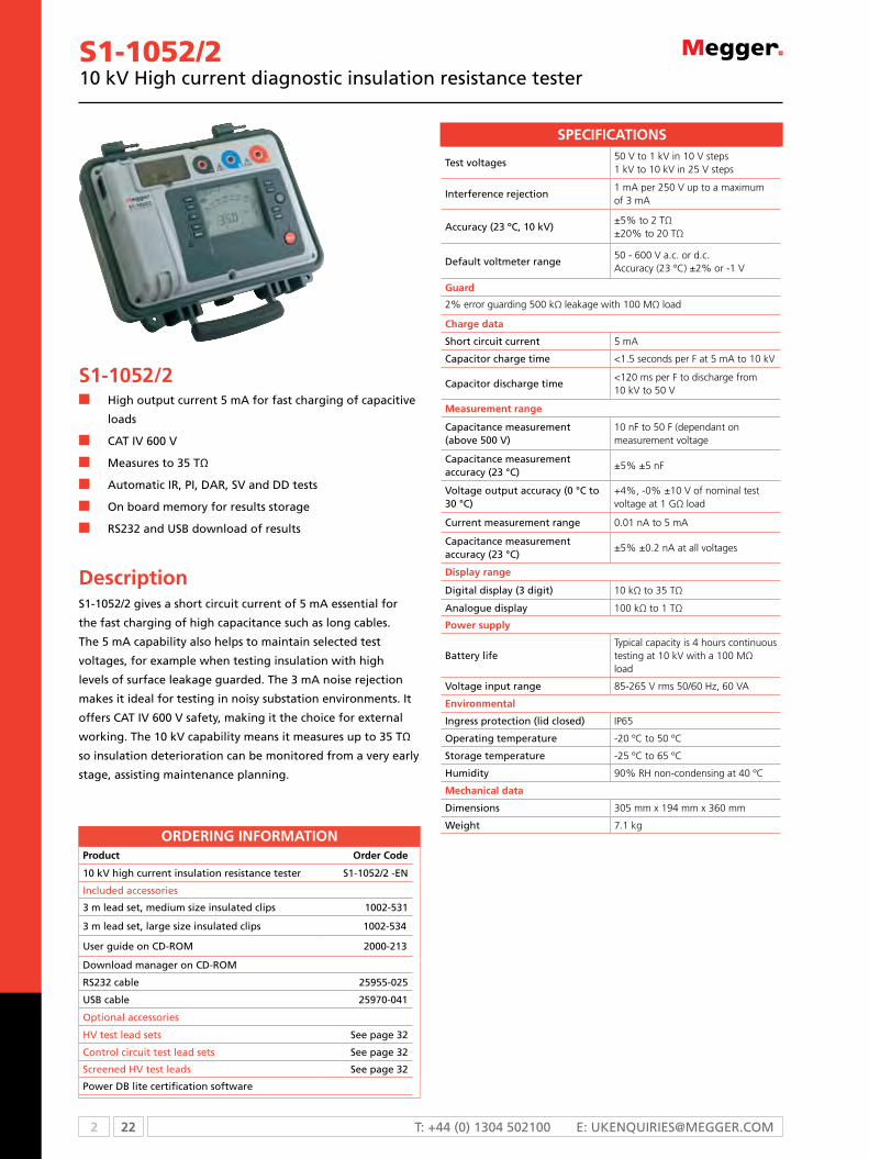
2 22 T: +44 (0) 1304 502100 E: [email protected]
S1-1052/210 kV High current diagnostic insulation resistance tester
Test voltages50 V to 1 kV in 10 V steps 1 kV to 10 kV in 25 V steps
interference rejection1 mA per 250 V up to a maximum of 3 mA
Accuracy (23 ºc, 10 kV)±5% to 2 TΩ±20% to 20 TΩ
Default voltmeter range50 - 600 V a.c. or d.c.Accuracy (23 ºC) ±2% or -1 V
Guard
2% error guarding 500 kΩ leakage with 100 MΩ load
Charge data
short circuit current 5 mA
capacitor charge time <1.5 seconds per F at 5 mA to 10 kV
capacitor discharge time<120 ms per F to discharge from 10 kV to 50 V
Measurement range
capacitance measurement (above 500 V)
10 nF to 50 F (dependant on measurement voltage
capacitance measurement accuracy (23 °c)
±5% ±5 nF
Voltage output accuracy (0 °c to 30 °c)
+4%, -0% ±10 V of nominal test voltage at 1 GΩ load
current measurement range 0.01 nA to 5 mA
capacitance measurement accuracy (23 °c)
±5% ±0.2 nA at all voltages
Display range
Digital display (3 digit) 10 kΩ to 35 TΩ
Analogue display 100 kΩ to 1 TΩ
Power supply
Battery lifeTypical capacity is 4 hours continuous testing at 10 kV with a 100 MΩload
Voltage input range 85-265 V rms 50/60 Hz, 60 VA
Environmental
ingress protection (lid closed) IP65
operating temperature -20 ºC to 50 ºC
storage temperature -25 ºC to 65 ºC
Humidity 90% RH non-condensing at 40 ºC
Mechanical data
Dimensions 305 mm x 194 mm x 360 mm
Weight 7.1 kg
SPECIFICATIONS
S1-1052/2n High output current 5 mA for fast charging of capacitive
loads
n cAT iV 600 V
n measures to 35 TΩ
n Automatic ir, Pi, DAr, sV and DD tests
n on board memory for results storage
n rs232 and usB download of results
Descriptions1-1052/2 gives a short circuit current of 5 mA essential for
the fast charging of high capacitance such as long cables.
The 5 mA capability also helps to maintain selected test
voltages, for example when testing insulation with high
levels of surface leakage guarded. The 3 mA noise rejection
makes it ideal for testing in noisy substation environments. it
offers cAT iV 600 V safety, making it the choice for external
working. The 10 kV capability means it measures up to 35 TΩ
so insulation deterioration can be monitored from a very early
stage, assisting maintenance planning.
ORDERING INFORMATIONProduct Order Code
10 kV high current insulation resistance tester s1-1052/2 -En
included accessories
3 m lead set, medium size insulated clips 1002-531
3 m lead set, large size insulated clips 1002-534
user guide on cD-rom 2000-213
Download manager on cD-rom
rs232 cable 25955-025
usB cable 25970-041
optional accessories
HV test lead sets see page 32
control circuit test lead sets see page 32
screened HV test leads see page 32
Power DB lite certification software

23 2WWW.mEggEr.com
S1-554/25 kV Diagnostic insulation resistance tester with high noise rejection
S1-554/2n 4 mA noise rejection with firmware filtering
n 5 mA short circuit current output
n cAT iV 600 V
n measures to 15 TΩ
n Automatic ir, Pi, DAr, sV and DD tests
n on board memory for results storage
Descriptions1-554/2 gives a short circuit current of 5 mA essential for
the fast charging of high capacitance such as long cables. The
5 mA capability also helps to maintain selected test voltages,
for example when testing insulation with high levels of surface
leakage guarded. The 4 mA noise rejection with firmware time
constant filtering makes it the perfect instrument for testing
in high-noise environments such as HV switch yards. it offers
cAT iV 600 V safety, making it the choice for external working.
Because it measures up to 15 TΩ, insulation deterioration can
be monitored from an early stage, assisting maintenance
planning.
Test voltages50 V to 1 kV in 10 V steps 1 kV to 5 kV in 25 V steps
interference rejection1 mA per 250 V up to a maximum of 4 mA
Firmware filter10, 30 and 100 second time constants (selectable)
Accuracy (23 ºc, 5 kV)±5% to 1 TΩ±20% to 10 TΩ
Default voltmeter range50 - 600 V a.c. or d.c.Accuracy (23 ºC) ±2% or -1 V
Guard
2% error guarding 500 kΩ leakage with 100 MΩ load
Charge data
short circuit current 5 mA
capacitor charge time <1.5 seconds per F at 5 mA to 5 kV
capacitor discharge time<120 ms per F to discharge from 5 kV to 50 V
Measurement range
capacitance measurement (above 500 V)
10 nF to 50 F (dependant on measurement voltage
capacitance measurement accuracy (23 °c)
±5% ±5 nF
Voltage output accuracy (0 °c to 30 °c)
+4%, -0% ±10 V of nominal test voltage at 1 GΩ load
current measurement range 0.01 nA to 5 mA
capacitance measurement accuracy (23 °c)
±5% ±0.2 nA at all voltages
Display range
Digital display (3 digit) 10 kΩ to 15 TΩ
Analogue display 100 kΩ to 1 TΩ
Power supply
Battery lifeTypical capacity is 6 hours continuous testing at 5 kV with a 100 MΩload
Voltage input range 85-265 V rms 50/60 Hz, 60 VA
Environmental
ingress protection (lid closed) IP65
operating temperature -20 ºC to 50 ºC
storage temperature -25 ºC to 65 ºC
Humidity 90% RH non-condensing at 40 ºC
Mechanical data
Dimensions 305 mm x 194 mm x 360 mm
Weight 7.1 kg
SPECIFICATIONS
ORDERING INFORMATIONProduct Order Code
5 kV insulation resistance tester with high noise rejection
s1-554/2 -En
included accessories
3 m lead set, medium size insulated clips 1002-531
user guide on cD-rom 2000-213
Download manager on cD-rom
rs232 cable 25955-025
usB cable 25970-041
Product Order Code
optional accessories
HV test lead sets see page 32
control circuit test lead sets see page 32
screened HV test leads see page 32
Power DB lite certification software

2 24 T: +44 (0) 1304 502100 E: [email protected]
S1-1054/210 kV Diagnostic insulation resistance tester with high noise rejection
SPECIFICATIONS
S1-1054/2n 4 mA noise rejection with firmware filtering
n 5 mA short circuit current output
n cAT iV 600 V
n measures to 35 TΩ at 10000 V
n Automatic ir, Pi, DAr, sV and DD tests
n on board memory for results storage
Descriptions1-1054/2 gives a short circuit current of 5 mA essential for
the fast charging of high capacitance such as long cables.
The 5 mA capability also helps to maintain selected test
voltages, for example when testing insulation with high
levels of surface leakage guarded. The 4 mA noise rejection
with firmware time constant filtering makes it the perfect
instrument for testing in high-noise environments such as HV
switch yards. it offers cAT iV 600 V safety, making it the choice
for external working. The 10 kV capability means it measures
up to 35 TΩ so insulation deterioration can be monitored from
a very early stage, assisting maintenance planning.
ORDERING INFORMATIONProduct Order Code
10 kV high current insulation resistance tester s1-1054/2 -En
included accessories
3 m lead set, medium size insulated clips 6220-820
3 m lead set, large size insulated clips 6220-811
user guide on cD-rom 2000-213
Download manager on cD-rom
rs232 cable 25955-025
usB cable 25970-041
Product Order Code
optional accessories
HV test lead sets see page 32
control circuit test lead sets see page 32
screened HV test leads see page 32
Power DB lite certification software
Test voltages50 V to 1 kV in 10 V steps 1 kV to 10 kV in 25 V steps
interference rejection1 mA per 250 V up to a maximum of 4 mA
Firmware filter10, 30 and 100 second time constants (selectable)
Accuracy (23 ºc, 5 kV)±5% to 2 TΩ±20% to 20 TΩ
Default voltmeter range50 - 600 V a.c. or d.c.Accuracy (23 ºC) ±2% or -1 V
Guard
2% error guarding 500 kΩ leakage with 100 MΩ load
Charge data
short circuit current 5 mA
capacitor charge time <1.5 seconds per F at 5 mA to 10 kV
capacitor discharge time<120 ms per F to discharge from 10 kV to 50 V
Measurement range
capacitance measurement (above 500 V)
10 nF to 50 F (dependant on measurement voltage
capacitance measurement accuracy (23 °c)
±5% ±5 nF
Voltage output accuracy (0 °c to 30 °c)
+4%, -0% ±10 V of nominal test voltage at 1 GΩ load
current measurement range 0.01 nA to 5 mA
capacitance measurement accuracy (23 °c)
±5% ±0.2 nA at all voltages
Display range
Digital display (3 digit) 10 kΩ to 35 TΩ
Analogue display 100 kΩ to 1 TΩ
Power supply
Battery lifeTypical capacity is 4 hours continuous testing at 10 kV with a 100 MΩload
Voltage input range 85-265 V rms 50/60 Hz, 60 VA
Environmental
ingress protection (lid closed) IP65
operating temperature -20 ºC to 50 ºC
storage temperature -25 ºC to 65 ºC
Humidity 90% RH non-condensing at 40 ºC
Mechanical data
Dimensions 305 mm x 194 mm x 360 mm
Weight 7.1 kg
SPECIFICATIONS

25 2WWW.mEggEr.com
S1-5010Diagnostic insulation tester
SPECIFICATIONS
Test voltages500, 1000, 2500, 5000 V 25 to 5000 V in 25 V steps
Test voltage accuracy±5% on 10 MΩ load and above±2 V for test voltages <500 V±12 V for test voltages <125 V
nominal test current limit 2 mA or 5 mA (selectable)
charge time<5 s per µF at 2 mA<2.5 s per µF at 5 mA
Measurement ranges
Digital resistance
10 kΩ to 500 GΩ @ 500 V10 kΩ to 1 TΩ @ 1000 V10 kΩ to 2.5 TΩ @ 2500 V10 kΩ to 5 TΩ @ 5000 V
Voltage50 to 1000 V ac/dc (5000 V when testing)
current 0.01 nA to 999 µA
capacitor 0.01 µF - 10.0 µF
Analogue
resistance 10 kΩ to 1 TΩ
Accuracy (0 to 30 ºC) (32 to 86 ºF)
resistance±5% of reading (1 MΩ to 1 TΩ @ 5 kV)
Dc test voltage ±2% ±1 V
current ±5% ±0.2 nA
capacitance ±5% ±0.01 µF
interference rejection4 mA at 50/60 Hz for <5% additional error
maximum capacitance discharge rating
20.0 µF
Guard terminal
Guards out parallel resistance down to 250 kΩMaximum additional error 5% @ 100 MΩ
operational supply95 - 280 V ac12 - 15 V ac or dc
Test time 15 seconds to 90 minutes
Battery
internal rechargeable 12 V, 7 Ah lead acid battery
Battery lifeAt least 8 hours from a fully chargedbattery
Battery indicator Bargraph level indicator
Display
Backlit dot matrix LCD (256 x 128 pixels)
Safety
Conforms to IEC 61010-1 voltmeter rated for use on 300 V phase to earth systems, category III
Environmental
ingress protection (with side door closed)
IP654
operating temperature -20 ºC to 50 ºC (-4 to +122 ºF)
storage temperature -25 ºC to 65 ºC (-13 to 149 ºF)
Humidity90% RH non-condensing at 40 ºC (104 ºF)
Mechanical data
Dimensions327 x 316 x 196 mm (12.8 x 12.4 x 7.7 in.)
Weight 9 kg (19.8 lbs)
SPECIFICATIONS
S1-5010n High specification 5 kV tester
n Automatic test sequences
n PC control and display option
n On-board results storage
n Heavy duty, mains/battery operation
n User defined test procedures with software
DescriptionThe S1-5010 is an advanced insulation tester for measurement
of insulation resistance of all types of electrical equipment.
The instrument performs automatic tests, enabling consistent
operation without operator input. It stores results and can
be operated from a PC. Flexible power supply options and
robust, portable construction allow the instrument to be used
in a wide variety of applications. It is particularly suitable for
analysing the insulation of large machines, HV generators and
cables.
ORDERING INFORMATIONProduct Order Code
Dignostic insulation tester s1-5010
included accessories
3 x 3 m (10 ft) HV leads 8101-181
rs232 communication lead 25955-025
Pc download software 6220-652
Test record cards (5) 6172-112
Accessory pouch 6420-116
user guide 6172-283
optional accessories
Fused test lead set 6320-240
3 x 8 m (25 ft) HV leads 8101-182
3 x 15 m (50 ft) HV leads 8101-183
shielded test lead set 15 m (50 ft) 6311-080
12 V dc automative charging lead 6231-584
s1-s1 Pc software for remote operation and data storage
6220-644
cB101, 5 kV calibration box 6311-077

2 26 T: +44 (0) 1304 502100 E: [email protected]
MJ15 and BM15Analogue 5 kV insulation testers
Insulation range
100 kΩ to 20 GΩ (also 0 Ω and ∞)
Test voltages (d.c.)
500 V, 1000 V, 2500 V and 5000 V
Test voltage accuracy
±5% of nominal test voltages on 20 MΩ load
Accuracy
±2,5% f.s.d. a.c. (with rotary switch in the V position)
Terminal voltage characteristics
Environmental
operational temperature0 ºC to 30 ºC at full specification-20 ºC to 50 ºC with temperature coefficient ±1%/ ºC
storage temperature -25 ºC to 65 ºC
Humidity range 90% RH at 40 ºC
Power supply
Low voltage brushless generator and 8 x AA cells (LR6 or rechargeable)
Mechanical data
Dimensions (H x W x D) 220 mm x 160 mm x 115 mm
Weight Bm15 1.2 kg
Weight mJ151.6 kg or 1.8 kg with battery holder and cells
ORDERING INFORMATIONProduct Order Code
Hand crank/battery 5 kV insulation tester mJ15
Battery powered 5 kV insulation tester Bm15
included accessories
user guide 6172-209
3 x 3 m HV leads 8101-181
carrying case with lead storage 6420-117
slide in pass band overlay (5 supplied) 6121-401
Test record card (pack of 5) (u.s 210949)
8 x AA cells (Lr6 or rechargeable)
Product Order Code
optional accessories
Fused test probes, 1,5 m long (2 used) 6320-240
Test record card (Pack of 20) 6111-216
cB101; 5 kV calibration box 6311-077
MJ15 and BM15 n Four test voltages to 5 kV
n Dual power supply option
(mJ15) giving the best of both
worlds
n resilient mounted analogue
scale for robustness
n Voltage range to 600 V
indicates auto discharge
n Pass/fail overlays for rapid testing
n single scale for insulation values to avoid operator error
DescriptionBm15 and mJ15 are compact 5 kV insulation testers. They are
very simple to use and provide a quick and accurate reading
of insulation resistance. The instruments use an analogue
display with a maximum reading of 20 gΩ. The Bm15 is
powered by batteries only. The mJ15 has an additional hand-
cranked generator.
The Bm15 is powered by 8 x Lr6 (AA) alkaline cells. The mJ15
comes with a hand cranked generator plus batteries. if the
test button is pressed the mJ15 uses battery power. otherwise
the crank handle is turned to save battery power or for use
when the batteries are unavailable.
If you need...a 5 kV insulation tester with very high noise rejection (for example if you are working in an electrically noisy substation), then s1-554/2 might be what you need
See page 23
SPECIFICATIONS

27 2WWW.mEggEr.com
See page 18
5 and 15 kV Megohmmetermegohmmeters
Megohmmeter n continuously variable test voltage
n rugged field construction
n circuit-breaker protection
DescriptionThe 5 and 15 kV Megohmmeters are high-voltage, line-
operated instruments. They provide a continuously variable
test voltage for highly sensitive insulation resistance measure-
ments of all types of electrical equipment and power cable.
The instruments are designed to withstand harsh field
conditions, and feature tough, impact-resistance casing,
removable lids and adjustable carrying straps. For complete
portability, there is ample room in each case to store cables
and the instruction manual.
ORDERING INFORMATIONProduct Order Code
5 kV megohmmeter 210400
15 kV megohmmeter 210415
included accessories
ground connection cable, 3 m (10 ft) 4702
Test record card, universal 210954
Power cord, for cAT no. 17032
instruction manual for 5 kV model AVTm21-40JA
instruction manual for 15 kV modelAVTm21-
415JA
Product Order Code
optional accessories
Test record card, 0 to 1000 gΩ 210959
Test report sheet for rotating equipment 210951-1
Test report sheet for power transformers 210951-2
Test report sheet for power cables 210951-3
Bushing guard spring 217003
“Lowdown on HV Dc Testing” manual AVTm22P-1
“A stitch in Time” manual AVTm21-P8B
input voltage 120 Vac, 60 Hz
For 220/240 V ac 50/60 Hz operation, add -47 to catalogue number
output current 5 kV megohmmeter
5 mA continuous
output current 15 kV megohmmeter
2 mA continuous (stabiliser out)50 µA continuous (at 15 kV, stabliser in)
short circuit current 12 mA max.
Environmental
operating temperature -17.7 to +50 ºC (0 to 122 ºF)
Mechanical data
5 kV Dimensions (H x W x D)
254 x 260 x 355 mm (10 x 10.2 x 14 inches)
15 kVDimensions (H x W x D)
317 x 292 x 514 mm(12.5 x 11.5 x 20.2 inches)
5 kV Weight 9.3 kg (20.5 lb)
15 kV Weight 15.9 kg (35 lb)
SPECIFICATIONS
ApplicationsThe units are suitable for dielectric absorption and step
voltage testng. Two models are available:
The 5 kV Megohmmeter measures up to 100,000 MΩ;
provides output from 250 volts to 5 kV, with direct reading up
50,000 MΩ at 2.5 kV.
The 15 kV Megohmmeter provides direct reading measure-
ments up to 100,000 MΩ at 5 kV and up to 200,000 MΩ at
10 kV, with a multiplying factor for all other voltaes up to
15 kV.
The 15 kV model also features an internal voltage stabiliser
that may be activated for improved measurement under
extreme field conditions. Separate on/off controls are
provided for power and high voltage, and red light indicates
when high voltage is on.

2 28 T: +44 (0) 1304 502100 E: [email protected]
ORDERING INFORMATION
MIT30n continuously variable test voltage, 0 – 30 kV
n Test current 0 - 330 μA
n output voltage accuracy, + 1.5% (full scale)
n Built-in adjustable ionization indicator
n Fail-safe grounding and “zero-start” switches
DescriptionThe miT30 is a portable 30 kV insulation tester that has been
developed to satisfy the demand for a variety of high voltage,
high accuracy, low current applications. The miT30 is used to
undertake HV insulation tests (proof/ hi-pot test) on insulating
material where low levels of leakage current, down to an
accuracy of 100 nA, need to be measured.
The miT30 has a test current of up to 330 μA, and user
selectable trip levels from 0 to 360 μA, provide protection to
the test piece against flashovers (arcing) and further damage
in the event of a breakdown. An audible ionization indicator
gives an audio indication of any electrical discharges present
during the test period.
MIT30 30 kV HV insulation tester
Output
output0 to 30 kV dc (variable negative with respect to earth/ground)
maximum current 330 μA
Peak-peak ripple <0.4%
Line regulation 0.03%
Load regulation 0.001%
Current
330 μA continuousUser selectable trip from 0 to 360 μA
Accuracy
Voltage meter ±1.5% (full scale), 10 V resolution
current meter ±1.5% (full scale), 100 nA resolution
Input
mains ac/dc ac - 85 - 264 V ac, 47 - 440 Hz
dc - 110 - 350 V dc <75 VA
Environmental
operating temperature -10 ºC to +55 ºC (14 ºF to 131 ºF)
storage temperature -20 °C to +70 °C (-4 ºF to +158 ºF)
Humidity 0 to 90% RH (non-condensing)
maximum altitude (full rating) 1600 m (MSL)
ingress protectionIP67 when closed for transport (Def Stan 81-41/STANAG 4280)IP52 when in use
Mechanical data
Dimensions (H x W x D)360 mm x 304 mm x 194 mm(14 in x 12 x 8 in)
Weight 10 kg (22 lb)
SPECIFICATIONS
Product Order Code
30 kV high-voltage insulation tester miT30
included accessories
HV triaxial output cable, 3 m skrc080509
input power cord 17032
instruction manual AVTmmiT30
optional accessories
High voltage resistance discharge stick 222070-62
“The Lowdown on High-Voltage Dc Testing”guide
AVTm22P-1

29 2WWW.mEggEr.com
5 and 15 kVDielectric test sets
Input
120 Vac, 50/60 Hz
For 220/240 Vac, 50/60 Hz operation add -47 to catalogue number
Output
Cat. No. 220005
Voltage (maximum)0 to 5 kV dc, negative with respect to ground
current meter 5 mA continuous
Metering
kilovoltmeter102 mm (4 in.) taut band with two ranges, 0 to 2.5 and 0 to 5 kV
current meter102 mm (4 in.) taut band with four ranges, 0 to 5/50/500 μA and 5 mA
Cat. No. 220015
Voltage0 to 15 kV dc, negative with respect to ground
current 2 mA continuous
short circuit12 mA max., limited by circuit breaker
Metering
kilovoltmeter102 mm (4 in.) taut band with two ranges, 0 to 7.5 and 0 to 15.0 kV
current meter102 mm (4 in.) taut band with four ranges, 0 to 5/50/500 μA and 5 mA
Environmental
operating temperature –17.7 to +50 °C (-0 to 122 °F)
storage temperature -4 ºF to +158 ºF (-20 °C to +70 °C)
Humidity 0 to 90% RH (non-condensing)
maximum altitude (full rating) 1600 m (MSL)
ingress protectionIP67 when closed for transport (Def Stan 81-41/STANAG 4280)IP52 when in use
Mechanical data
Dimensions (H x W x D)360 mm x 304 mm x 194 mm(14 in x 12 x 8 in)
Weight 10 kg (22 lb)
SPECIFICATIONS
5 and 15 kVn continuously variable test voltage
n rugged field construction
n compact and portable
DescriptionDielectric test sets measure leakage current while applying a
dc voltage at or above the insulation system’s operating level.
This measurement aids in determining the insulation system’s
ability to withstand overvoltages such as lightning strikes and
switching surges.
Two models are available; a 5 kV unit for testing equipment
rated 2.5 kV and below, and a 15 kV model for use on
equipment rated 7.5 kV and below. Both are suitable for
testing power cable, switchgear and rotating machinery in
accordance with iEEE, icEA, nEmA and Ansi guidelines.
Because megger dc dielectric test sets act like full-wave
rectified units, they also are suitable for applications involving
vacuum bottles.
ORDERING INFORMATIONProduct Order Code
5 kV 220005
15 kV 220015
included accessories
ground connection cable, 3 m [10 ft] 4702
kV/mΩ test record graph paper (100 sheet pad) 220000
Power cord, cat. no. 220015 17032
instruction manual, cat. no. 220005 AVTm22-5JB
instruction manual, cat. no. 220015 AVTm22-15JA
optional accessories
strip chart recorder 220003
High-voltage resistance discharge stick 222070-62
internal voltage stabilizer, cat. no. 220015 only Add –50
special cable lengths Add –56
“The Lowdown on High-Voltage Dc Testing” AVTm22P-1

2 30 T: +44 (0) 1304 502100 E: [email protected]
70, 120, 160 kV High voltage Dc dielectric test sets
70, 120, 160 kV n Lightest weight available in air-insulated
high-voltage model
n Advanced performance with long-term
reliability provided by filtered half-wave
rectification
n Designed for maximum operator safety
DescriptionThe high voltage Dc dielectric test sets (70, 120 and
160 kV) provide the most dependable, portable dc
highvoltage sources for checking the quality of electrical
power cables, motors, switchgear, insulators, transformers and
capacitors.
ApplicationsThe Dc dielectric test sets are used to make proof tests and
insulation tests on electrical power cables, motors, switchgear,
insulators, transformers and capacitors.
Both types of tests are performed by applying controlled
high voltages to the unit under test at or above insulation
system operating level. measuring the leakage current
helps determine the unit under test’s ability to withstand
overvoltages such as lightning strikes and switching surges.
The three models described cover a range of output voltages
that meet the most commonly specified ratings in 5 kV to
69 kV class cable. All are suitable for testing power cable,
switchgear and rotating machinery in accordance with iEEE,
iPcEA, nEmA and Ansi guidelines.
SPECIFICATIONSInput Power
Nominal 120 Vac, 50/60 HzFor 220/240 Vac, 50/60 Hz operation, add –47 to Cat. No.
Please note that specifications for the –47 models differ asfollows:
output current
220/240 Vac120 kV models: 5 mA for 5 min; 2 mA continuous160 kV models: 5 mA for 5 min; 1.5 mA continuousWhen using external 240/120 volt step-down voltage transformers,the ratings may be used as given for 120 volt input.
WeightAdd approx. 1 kg (2 lb) for -47 control unit
Ammeter
ranges
0 to 19.9 μA0 to 199 μA0 to 1.99 mA0 to 5 mA
resolution To 0.1 mA on lowest range
Accuracy ±2% of reading +1 digit
Voltmeter
resolution To 100 V over entire range
Accuracy ± (2% of reading + 100 V)
Ripple
Less than 2% on capacitive samples at continuous rated output
Environmental
Relative humidity range
operating 0 to 90% noncondensing
storage 0 to 95% noncondensing
Mechanical data
Dimensions (H x W x D)control unit (all models)
510 x 305 x 318 mm.(20 x 12 x 12.5 in)
High voltage unit70 kV: 510 x 305 x 305 mm (20 x 12 x 12 in.)
120 kV: 740 x 305 x 305 mm (29 x 12 x 12 in.)
160 kV: 1000 x 305 x 305 mm (39 x 12 x 12 in.)
Weight
control unit (all models0 10.5 kg (23 lb)
High voltage unit70 kV: 20 kg (44 lb)120 kV: 30 kg (65 lb)160 kV: 33 kg (73 lb)
cables (including carrying bag)70 kV: 3 kg (7 lb)120 and 160 kV: 4 kg (9 lb)

31 2WWW.mEggEr.com
70, 120, 160 kV High voltage Dc dielectric test sets
ORDERING INFORMATIONProduct Order Code
Dielectric test sets
70 kV dc, digital 220070
70 kV dc, analog 220072
120 kV dc, digital 220123
120 kV dc, analog 220124
160 kV dc, digital 220163
160 kV dc, analog 220164
For 220/240 Vac, 50/60 Hz operation, add –47 to cat. no.
included accessories
input supply cord, three-wire, 2.4 m (8 ft) 17032
ground cables, 4.5 m (15 ft) [2] 4702-5
interconnection cable, 4.5 m (15 ft) 18320
Detachable HV output cable, for 70 kV test sets,4.5 m (15 ft)
18328
Detachable HV output cable, for 120 and 160 kVtest sets, 4.5 m (15 ft)
25950
carrying bag for cables 18313
kilovolt/megohm test record graph paper(100 sheet pad)
220000
Product Order Code
optional accessories
modification of dc test, when ordered, setfor operation with an accessory impulse generator
add –61
External voltage stabilizer 220004
return probe for ac models only 230315-3
High-voltage and return probe set for ac/dc model only
230425-2
Adapters, for conversion of output receptacles for use with twist-lock plugs
nEmA L5-15r twist lock 235300-1
nEmA L5-20r twist lock 235300-2
nEmA L5-30r twist lock 235300-4
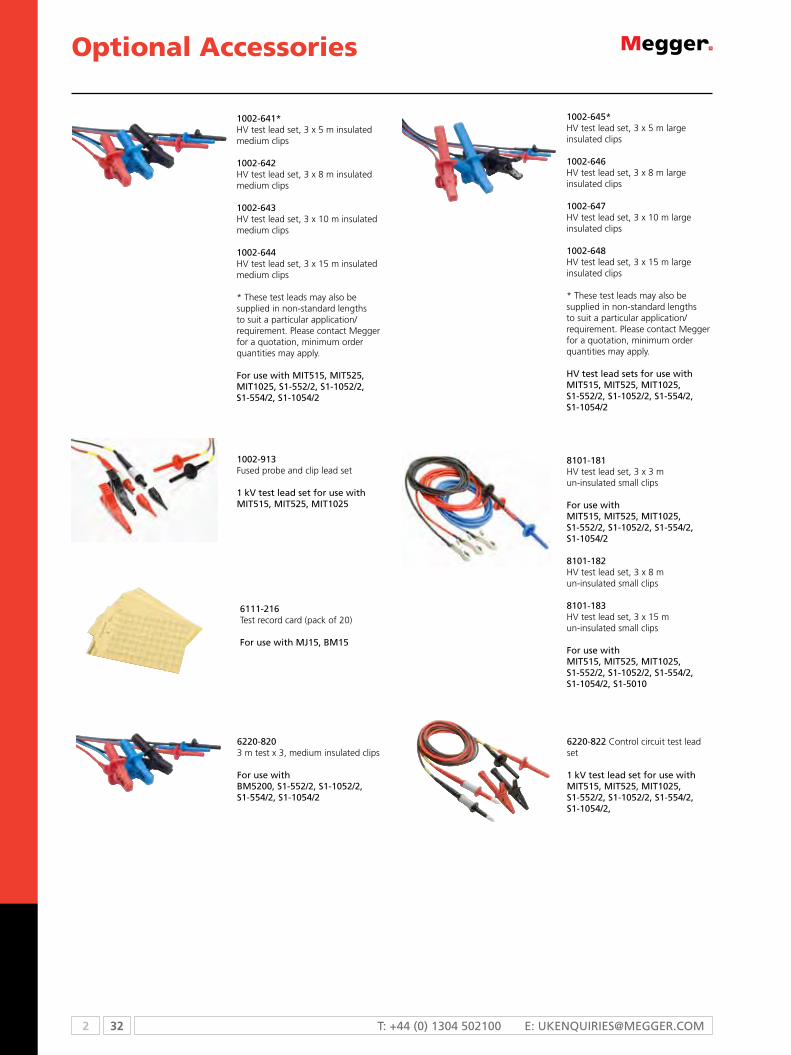
2 32 T: +44 (0) 1304 502100 E: [email protected]
Optional Accessories
8101-181HV test lead set, 3 x 3 m un-insulated small clips
For use withmiT515, miT525, miT1025, s1-552/2, s1-1052/2, s1-554/2,s1-1054/2
8101-182HV test lead set, 3 x 8 m un-insulated small clips
8101-183HV test lead set, 3 x 15 m un-insulated small clips
For use withmiT515, miT525, miT1025, s1-552/2, s1-1052/2, s1-554/2,s1-1054/2, s1-5010
1002-641*HV test lead set, 3 x 5 m insulated medium clips
1002-642HV test lead set, 3 x 8 m insulated medium clips
1002-643HV test lead set, 3 x 10 m insulated medium clips
1002-644HV test lead set, 3 x 15 m insulated medium clips
* These test leads may also be supplied in non-standard lengths to suit a particular application/requirement. Please contact Megger for a quotation, minimum order quantities may apply.
For use with miT515, miT525, miT1025, s1-552/2, s1-1052/2, s1-554/2, s1-1054/2
6111-216Test record card (pack of 20)
For use with mJ15, Bm15
6220-8203 m test x 3, medium insulated clips
For use withBm5200, s1-552/2, s1-1052/2,s1-554/2, s1-1054/2
1002-913Fused probe and clip lead set
1 kV test lead set for use with miT515, miT525, miT1025
1002-645*HV test lead set, 3 x 5 m large insulated clips
1002-646HV test lead set, 3 x 8 m large insulated clips
1002-647HV test lead set, 3 x 10 m large insulated clips
1002-648HV test lead set, 3 x 15 m large insulated clips
* These test leads may also be supplied in non-standard lengths to suit a particular application/requirement. Please contact Megger for a quotation, minimum order quantities may apply.
HV test lead sets for use with miT515, miT525, miT1025, s1-552/2, s1-1052/2, s1-554/2,s1-1054/2
6220-822 Control circuit test lead set
1 kV test lead set for use with miT515, miT525, miT1025,s1-552/2, s1-1052/2, s1-554/2,s1-1054/2,
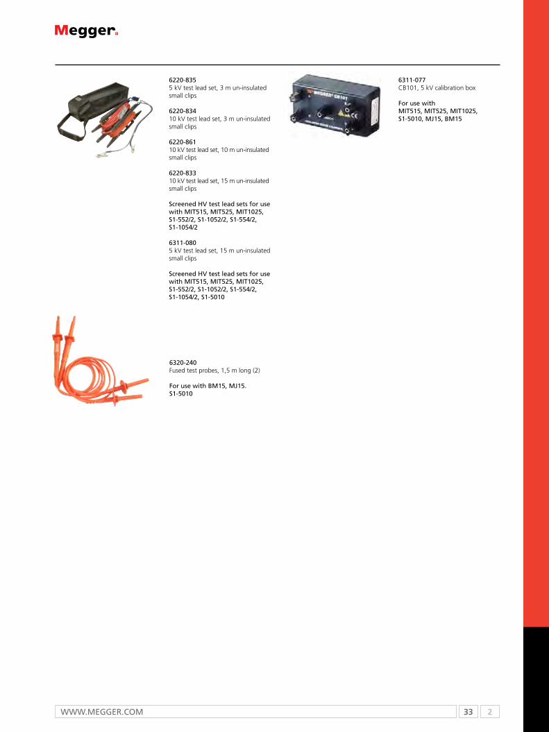
33 2WWW.mEggEr.com
6311-077CB101, 5 kV calibration box
For use withmiT515, miT525, miT1025, s1-5010, mJ15, Bm15
6320-240Fused test probes, 1,5 m long (2)
For use with Bm15, mJ15. s1-5010
6220-8355 kV test lead set, 3 m un-insulated small clips
6220-83410 kV test lead set, 3 m un-insulated small clips
6220-86110 kV test lead set, 10 m un-insulated small clips
6220-83310 kV test lead set, 15 m un-insulated small clips
screened HV test lead sets for use with miT515, miT525, miT1025, s1-552/2, s1-1052/2, s1-554/2,s1-1054/2
6311-0805 kV test lead set, 15 m un-insulated small clips
screened HV test lead sets for use with miT515, miT525, miT1025, s1-552/2, s1-1052/2, s1-554/2,s1-1054/2, s1-5010

2 34 T: +44 (0) 1304 502100 E: [email protected]
Selection guide ........................................................................................... 35IDAX300 insulation diagnostic analyzer ....................................................... 36CDAX605 high-precision capacitance and dissipation factor measurement instrument .................................................................................................. 38DELTA4000 12 kV insulation diagnostic system ........................................... 40CB100 low capacitance power factor test set .............................................. 43AC and AC/DC high pot tester .................................................................... 44670025 series capacitance and dissipation factor test set ............................ 46Optional accessories .................................................................................... 48
2b
Accurate and reliable condition assessment of insulations in transformers, bushings, generators and cables is essential to substation maintenance. These diagnostic insulation testing systems maximize the outcome of maintenance activities allowing for load and service life optimization.
AC Insulation Testers

35 2WWW.mEggEr.com
Application/Measurement CB100 CDAX605 IDAX/VAX 67005DELTA4000
Ac and Ac Dc high pot
Power frequency tan delta/power factor n n n n n
Capacitance measurements n n n n n
High voltage tan delta/power factor n n n n
High current/power tan delta/power factor n n
Laboratory precision measurements n
Dielectric frequency response n0.1 mHz -
10 kHz1-500 Hz
Moisture assessment n
Individual temperature correction n n
Temperature dependance analysis n
Tip-up testing n n n
High-pot testing n n n n n
If you need...other transformer test equipment,see page 254
SELECTION GUIDE
n feature
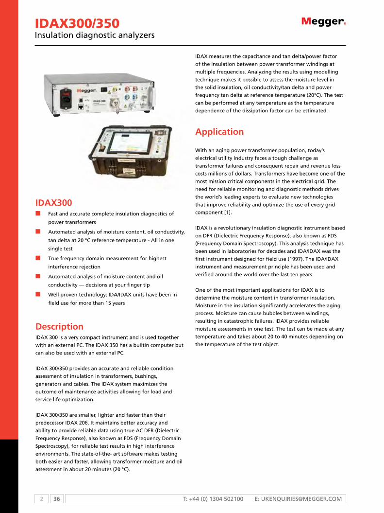
2 36 T: +44 (0) 1304 502100 E: [email protected]
IDAX300/350Insulation diagnostic analyzers
IDAX300n Fast and accurate complete insulation diagnostics of
power transformers
n Automated analysis of moisture content, oil conductivity,
tan delta at 20 °C reference temperature - All in one
single test
n True frequency domain measurement for highest
interference rejection
n Automated analysis of moisture content and oil
conductivity — decisions at your finger tip
n Well proven technology; IDA/IDAX units have been in
field use for more than 15 years
DescriptionIDAX 300 is a very compact instrument and is used together
with an external PC. The IDAX 350 has a builtin computer but
can also be used with an external PC.
IDAX 300/350 provides an accurate and reliable condition
assessment of insulation in transformers, bushings,
generators and cables. The IDAX system maximizes the
outcome of maintenance activities allowing for load and
service life optimization.
IDAX 300/350 are smaller, lighter and faster than their
predecessor IDAX 206. It maintains better accuracy and
ability to provide reliable data using true AC DFR (Dielectric
Frequency Response), also known as FDS (Frequency Domain
Spectroscopy), for reliable test results in high interference
environments. The state-of-the- art software makes testing
both easier and faster, allowing transformer moisture and oil
assessment in about 20 minutes (20 °C).
IDAX measures the capacitance and tan delta/power factor
of the insulation between power transformer windings at
multiple frequencies. Analyzing the results using modelling
technique makes it possible to assess the moisture level in
the solid insulation, oil conductivity/tan delta and power
frequency tan delta at reference temperature (20°C). The test
can be performed at any temperature as the temperature
dependence of the dissipation factor can be estimated.
Application
With an aging power transformer population, today’s
electrical utility industry faces a tough challenge as
transformer failures and consequent repair and revenue loss
costs millions of dollars. Transformers have become one of the
most mission critical components in the electrical grid. The
need for reliable monitoring and diagnostic methods drives
the world’s leading experts to evaluate new technologies
that improve reliability and optimize the use of every grid
component [1].
IDAX is a revolutionary insulation diagnostic instrument based
on DFR (Dielectric Frequency Response), also known as FDS
(Frequency Domain Spectroscopy). This analysis technique has
been used in laboratories for decades and IDA/IDAX was the
first instrument designed for field use (1997). The IDA/IDAX
instrument and measurement principle has been used and
verified around the world over the last ten years.
One of the most important applications for IDAX is to
determine the moisture content in transformer insulation.
Moisture in the insulation significantly accelerates the aging
process. Moisture can cause bubbles between windings,
resulting in catastrophic failures. IDAX provides reliable
moisture assessments in one test. The test can be made at any
temperature and takes about 20 to 40 minutes depending on
the temperature of the test object.
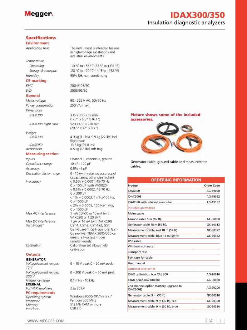
37 2WWW.mEggEr.com
Specifications EnvironmentApplication field The instrument is intended for use
in high-voltage substations and industrial environments.
Temperature
Operating -10 °C to +55 °C (32 °F to +131 °F)
Storage & transport -20 °C to +70 °C (-4 °F to +158 °F)
Humidity 95% RH, non-condensing
CE-markingEMC 2004/108/EC
LVD 2006/95/EC
GeneralMains voltage 90 - 265 V AC, 50 / 60 Hz
Power consumption 250 VA (max)
Dimensions
IDAX300 335 x 300 x 99 mm (17.7” x 6.3” x 16.1”)
IDAX300 flight case 520 x 430 x 220 mm (20.5” x 17” x 8.7”)
WeightIDAX300
IDAX350Accessories
4.9 kg (11 lbs), 9.9 kg (22 lbs) incl. flight case13.5 kg (29.8 lbs)8.5 kg (18 lbs) soft bag
Measuring sectionInputs Channel 1, channel 2, ground
Capacitance range 10 pF - 100 µF
Accuracy 0.5% +1 pF
Dissipation factor range
Inaccuracy
Max AC interference
Max DC interferenceTest Modes*
Calibration
0 - 10 (with retained accuracy of capacitance; otherwise higher)< 0.5% + 0.0001, 45-70 Hz, C > 100 pF (with VAX020)< 0.5% + 0.0002, 45-70 Hz, C > 300 pF< 1% + 0.0003, 1 mHz-100 Hz, C > 1000 pF< 2% + 0.0005, 100 Hz-1 kHz, C > 1000 pF1 mA (IDAX) or 10 mA (with VAX020) or 1:20 SNR1 μA or 10 uA (with VAX020)UST-1, UST-2, UST-1+2, GST, GST-Guard-1, GST-Guard-2, GST-Guard-1+2. *IDAX 300S/350 can measure two test modessimultaneously.Calibration set allows field calibration
OutputsGENERATORVoltage/current ranges, 10 V
0 – 10 V peak 0 – 50 mA peak
Voltage/current ranges, 200 VFrequency rangeEXERNALFor VAX amplifiersPC requirementsOperating systemProcessorMemoryInterface
0 – 200 V peak 0 – 50 mA peak
0.1 mHz - 10 kHz
2 to 30 kV
Windows 2000/ XP / Vista / 7Pentium 500 MHz512 Mb RAM or moreUSB 2.0
ORDERING INFORMATIONProduct Order Code
IDAX300 AG-19090
IDAX300S AG-19092
IDAX350 with internal computer AG-19192
Included accessories
Mains cable
Ground cable 5 m (16 ft), GC-30060
Generator cable 18 m (59 ft), GC-30312
Measurement cable, red 18 m (59 ft) GC-30322
Measurement cable, blue 18 m (59 ft) GC-30332
USB cable
Windows software
Transport case
Soft case for cable
User manual
Optional accessories
IDAX calibration box CAL 300 AG-90010
IDAX demo box IDB300 AG-90020
2nd channel option (factory upgrade to IDAX300S)
AG-90200
Generator cable, 9 m (30 ft) GC-30310
Measurement cable, 9 m (30 ft), red GC-30320
Measurement cable, 9 m (30 ft), blue GC-30330
IDAX300/350Insulation diagnostic analyzers
Picture shows some of the included accessories.
Generator cable, ground cable and measurement cables.
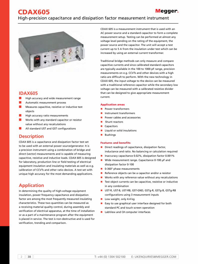
2 38 T: +44 (0) 1304 502100 E: [email protected]
CDAX605High-precision capacitance and dissipation factor measurement instrument
IDAX605n High accuracy and wide measurement range
n Automatic measurement process
n Measures capacitive, resistive or inductive test
objects
n High accuracy ratio measurements
n Works with any standard capacitor or resistor
value without any recalculations
n All standard UST and GST configurations
DescriptionCDAX 605 is a capacitance and dissipation factor test set
to be used with an external power source/generator. It is
a precision instrument using a combination of bridge and
direct (vector) measurements and is capable of measuring
capacitive, resistive and inductive loads. CDAX 605 is designed
for laboratory, production line or field testing of electrical
equipment insulation and insulating materials as well as e.g.
calibration of CCVTs and other ratio devices. A test set with
unique high accuracy for the most demanding applications.
ApplicationIn determining the quality of high-voltage equipment
insulation, power frequency capacitance and dissipation
factor are among the most frequently measured insulating
characteristics. These two quantities can be measured as
a receiving material quality control, during assembly and
verification of electrical apparatus, at the time of installation
or as a part of a maintenance program after the equipment
is placed in service. The test is non-destructive and is used for
verification, trending and comparison.
CDAX 605 is a measurement instrument that is used with an
AC power source and a standard capacitor to form a complete
measurement setup. Testing can be performed at almost any
voltage level pending on the rating of the equipment, the
power source and the capacitor. The unit will accept a test
current up to 5 A from the insulation under test which can be
increased by using an external current transformer.
Traditional bridge methods can only measure and compare
capacitive currents and since calibrated standard capacitors
are typically available in the 100 to 1000 pF range, precision
measurements on e.g. CCVTs and other devices with a high
ratio are difficult to perform. With the new technology in
CDAX 605, the input voltage to the device can be measured
with a traditional reference capacitor while the secondary low
voltage can be measured with a calibrated resistive divider
that can be designed to give appropriate measurement
current.
Application areas
n Power transformers
nInstrument transformers
n Power cables and accessories
nShunt reactors
n Capacitors
n Liquid or solid insulations
n Bushings
Features and benefits
n Direct readings of capacitance, dissipation factor,
inductance and ratio. No balancing or calculation required
nInaccuracy capacitance 0.02%, dissipation factor 0.001%
nWide measurement range. Capacitance 0-100 μF and
dissipation factor 0-100
n0-360° phase measurements
nReference objects can be a capacitor and/or a resistor
nWorks with any reference value without any recalculations
nTest object currents can be capacitive, resistive or inductive
in any combination
nUST-R, UST-B, UST-RB, GST-GND, GSTg-R, GSTg-B, GSTg-RB
configurations using 3 measurement inputs
nLow weight, only 4.4 kg
nEasy to use graphical user interface designed for both
standard PC and touch screen operation
nLabView and C# computer interfaces

39 2WWW.mEggEr.com
CDAX605High-precision capacitance and dissipation factor measurement instrument
Specifications EnvironmentApplication field The instrument is intended for use in
medium and high-voltage substations and industrial environments.
Temperature
Operating -20 °C to +55 °C (-4 °F to +131 °F)
Storage & transport -40 °C to 70 °C (-40 °F to +158 °F)
Humidity 95% RH, non-condensing
CE-markingEMC 2006/95/EC
LVD 2004/108/EC
GeneralMains voltage 100 – 240 V AC, 50/60 Hz
Power consumption 60 VA (max)
Dimensions
Instrument 335 x 300 x 99 mm (17.7” x 16.1” x 6.3”)
Transport case 520 x 430 x 220 mm (20.5” x 17” x 8.7”)
WeightInstrument 4.4 kg (9.7 lbs) (instrument only)
SoftwareCDAX 605 Control(LabView interface as an option
n Reference capacitance and/or resistor data entry
n Voltage measurements
n Current measurements
n Capacitance measurements
n Resistance measurements
n Inductance measurements
n Dissipation factor measurements
n Power factor measurements
n Phase measurements
n Ratio measurements
n Data log/storage in general format
PC requirements n Pentium 500 MHz/512 Mb or better
n Ethernet or USB communication
n Windows XP, Vista, Win 7
MeasurementChannels 2
Inputs 4 connectors, Cn, Cx1, Cx2 and ground BNC and UHF connectors
Measurement range Test frequency Test voltage
5 - 400 HzUnlimited (pending reference capacitor or resistor value only)
Capacitance Dissipation factor Current
0-100 µF0-1000-5 A (Can be increased by using input transformer)
PhaseInaccuracy* Capacitance
0-360º
±0.02% at 30 µA to 5 A measurement current
Voltage/current Dissipation factor
±0.5% of reading±(0.5% of reading + 0.001%)
PhaseCalibration
±0.01 mrad/0.4 minutesAutomatic self-calibration using an internal ratio-arm bridge.Note: Recommended full calibration interval < 2 years.
Max resolution Capacitance Dissiptation factor PhaseMeasurement timeWarm-up time
0.001 pF1x10-6
1x10⁻⁶
Selectable, default 2 s/measurement15 minutes for full accuracy
ORDERING INFORMATIONProduct Order Code
CDAX605 AI-19090
Included accessories
Mains cable
Ground cable
Ethernet cable
CIDAX605 Control (PC-SW)
Transport case
User manual
Optional accessories
Measurement cable, 6 m (20 ft) with UHF connectors
GC-30410
Measurement cable, 18 m (60 ft) with UHFconnectors
GC-30420
CDB605 demo box for CDAX AI-90010
CRD605 voltage divider 2 kV AI-90020
CDAX 605 Control
* The values for inaccuracy values are valid at test frequency 50/60 Hz, over full operating temperature range after warm up and self-calibration. THD of power source <10%.

2 40 T: +44 (0) 1304 502100 E: [email protected]
DELTA400012 kV Insulation diagnostic system
DELTA4000n Automatic and manual operation for power factor/tan
delta measurements
n Accurate and repeatable measurement results with high
noise suppression for the most extreme conditions
n Lightweight, rugged two-piece design, with unit weights
of 14 kg and 22 kg
n New built-in intelligent temperature correction
eliminates the need for temperature correction tables
(patent pending)
n New automatic voltage dependence detection (patent
pending)
DescriptionThe new DELTA4000 series is a fully automatic 12 kV insulation
power factor/dissipation factor (tan∂) test set designed for
condition assessment of electrical insulation in high voltage
apparatus such as transformers, bushings, circuit breakers,
cables, lightning arresters and rotating machinery. In addition
to performing insulation power factor tests, the DELTA4000
series can be used to measure the excitation current of
transformer windings as well as to perform automatic tip-up
tests and HV turns-ratio testing (an optional TTR capacitor is
available).
The test set is designed to provide a comprehensive AC
insulation diagnostic test. The high power variable frequency
design generates its own test signal independent of line
frequency quality and the hardware design uses the latest
technology available for digital filtering of the response
signal. As a result, the DELTA4000 series produces reliable
results and stable readings in the shortest time with the
highest accuracy, even in high interference 765 kV substations.
The DELTA4000 series operates with PowerDB software
for automatic testing and reporting or with Delta Control
software for real-time manual testing.
Measurements include voltage, current, power (loss), tan
delta, power factor and capacitance. The test results are
automatically stored in the computer and can also be
downloaded directly to USB storage or a printer.
At present two options are available, the DELTA4310 is a
complete stand alone test system with on-board PC control,
while the DELTA4110 requires an external computer.
DELTA4110 test set to be used with externalcomputer
DELTA4310 test set with onboard computer
Industry leading performance and accuracy
n Generates its own test signal - resulting in accurate and
clean measurements even in the most severe conditions
and in the event power is required from a portable
generator.
n High noise suppression and advanced signal acquisition
circuitry can handle up to 15 mA interference current or
a signal to noise ratio of up to 1:20 resulting in extremely
accurate and clean measurements even in the most severe
conditions.
n Industry leading frequency range (1-500 Hz) reveals
details in the insulation characteristics that are not possible
to detect with other test sets.
n Intelligent temperature correction (patent pending) allows
the user to estimate the actual temperature dependence
of the test object by measuring tan delta over a frequency
range. Mathematically calculating accurate individual
temperature correction results in a more accurate
measurement of the insulating material’s conditon.
n Automatic voltage dependence detection (patent
pending). Various high voltage components may have a
voltage dependence where tip-up testing is recommended
(i.e. the dissipation factor is pending test voltage). The
DELTA4000 series has a patented method for detecting
voltage dependence and gives the user an alarm,
suggesting additional tests should be performed at
different voltage levels.
n Fast test time - Dynamic nise suppression minimizes actual
test time.

41 2WWW.mEggEr.com
DELTA400012 kV Insulation diagnostic system
SPECIFICATIONS
Input power
90 - 264 V 45 - 66 Hz 16 A maxNo loss in performance when used with portable generator. Also possible to use 12 V dc with optional invertor kit (P/N 35271-16)
Output voltage 0 to 12 kV, continuously adjustable
Test frequency range
45-70 Hz (12 kV)15-400 Hz (4 kV)1-505 Hz (250 V)0.0001 Hz maximum resolution
Output power 3.6 kVA
Output current
300 mA (4 minutes)200 mA (30 minutes)100 mA (continuous)The power supply capacity can be expanded to 4 A at 12 kV using the optional resonating inductor, catalog number 670600
Measuring ranges
Voltage 25 V to 12 kV, 1 V resolution
Current0 to 5 amps, 0.1 µA maximum resolution. The measurement can be corrected to either 2.5 kV or 10 kV equivalents.
Capacitance 0 to 100 µF, 0.01 pF maximum resolution
Inductance6 H to 10 MH, 0.1 mH maximum resolution
Power factorPF 0-100% (0-1), 0.001% maximum resolution
Dissipation factorDF 0-100% (0-10.000%), 0.001% maximum resolution
Watt loss
0 to 2 kW, actual power, 0 to 100 kW when corrected to 10 kV equivalent 0.1 mW maximum resolution. The measurement can be corrected to either 2.5 kV or 10 kV equivalents.
Measurement (the following test modes are available)
usT: ungrounded specimen Testing UST-R: UST: Measure Red, Ground Blue UST-B: UST: Measure Blue, Ground Red UST-RB: UST: Measure Red and Blue
usT: grounded specimen Testing GST-GND: GST: Ground Red and Blue GSTg-R: GST: Guard Red, Ground Blue GSTg-B: GST: Guard Blue, Ground Red GSTg-RB GST: Guard Red and Blue
Temperature correction
Intelligent temperature correction
from 5 ºC to 50 ºC insulation test temperature to 20 ºC reference
Standard tablesas by international standards and manufacturers’ data
Environmental
Operating temperature -20 °C to +55 °C (-4 °F to +131 °F)
Storage temperature -50 °C to +70 °C (-58 °F to +158 °F)
Relative humidity 0 to 95% non-condensing
Shock and vibrationIEC 68-2-31, first edition, drop and topple (push over)IEC 68-2-31, second edition, free fall
SPECIFICATIONS Specifications continued
Safety
IEC/EN 61010-1:2001
EMC EN 61326
Mechancial data
Dimensions (W x H x D)
Control unit 290 x 290 x 460 mm (11 x 11 x 18 in.)
High voltage unit 290 x 290 x 460 mm (11 x 11 x 18 in.)
Weight
DELTA4100 Control unit 14 kg (31 lbs)
DELTA4300 Control unit 15 kg (33 lbs)
DELTA4010 High voltage unit
23 kg (48 lbs)
Cables 15 kg (33 lbs)
If you need...to detect potential mechanical and electrical problems that other methods are unable to, then the FrAX series of sweep frequency response analysers may be the answer. See page 277

2 42 T: +44 (0) 1304 502100 E: [email protected]
ORDERING INFORMATION
Product Order Code
DELTA4110 Insulation diagnostic system (DELTA4100 control unit and DELTA4010 HV unit)
DELTA4110
DELTA4310 Insulation diagnostic system with onboard computer(DELTA4300 control unit and DELTA4010 HV unit)
DELTA4310
Included accessories
High voltage lead: 21 m (70 ft), double shielded 30012-11
Measurement lead, color-coded Red 25572-1
Measurement lead, color-coded Blue 25572-2
Ground lead: 9 m (30 ft) 2002-131
Mains cable 25 A EU 17032-23
Mains cable16 A US 17032-20
Mains cable 16 A UK 17032-21
Mains cable 16 A no plug 17032-22
Safety hand switch, Interlock #1: 18 m (60 ft) 1001-850
Safety hand switch, Interlock #2: 2.5 m (8 ft) 1001-851
HV unit power cable, 1 m (3 ft) 2002-132
HV unit control cable, 1 m (3 ft) 2002-133
Ground lead cable, 1 m (3 ft) 2002-134
USB cable, 2 m (7 ft) CA-USB
Ethernet cable, CAT 5, 2 m (7 ft) 36798
Soft padded carrying case for control unit [1] 2001-766
Soft padded carrying case for HV unit [1] 2001-766
Soft case for HV cable 2001-507
Soft case for other cables/accessories 2001-506
User manual 81331
Warranty [1 year]
PowerDB software
Optional software
PowerDB Pro software, on USB dongle DB1001S-A
PowerDB Pro software, via soft key DB1001-A
Extended warranty and annual support
Priority access annual support plan D4K-P-ACCESS
Product warranty Y12-WARRANTY
Training D4K-TRAINING
PowerDB software maintenance and upgrades D4K-SOFTWARE
24/7 technical support D4K-TECHSUPPORT
Engineering consulting and results analysis D4K-ENGCONSULT
Loaner unit and accessories D4K-LOANER
Product Order Code
Optional accessories
Accessory kit: mini bushing tap connectors (2) P/N 670506 hot collar straps (3) P/N 670505, digital temperature and humidity meter (1) P/N 670504, .75” bushing tap connector (1) P/N 30918-000, 1” bushing tap connector (1) P/N 30918-100, “J” probe bushing tap connector (1), P/N 30917 1 m (3 ft) non-insulating shorting lead (3), P/N 34726-1 2 m (6 ft) non-insulating shorting lead (3), P/N 34726-2
670501
Digital temperature and humidity meter 670504
External temperature and humidity probes 2002-138
Safety foot switch 1001-852
External strobe, 3 m (3 ft) Y37181
External strobe extension cable, 18 m (60 ft) 1001-853
Transport case, 2-piece design kit, consists of:case for control unit and accessories (2001-746), case for HV unit and accessories (2001-746)
1001-932
Transport case, 3-piece design kit, consists of:case for control unit (2001-791), case for HV unit (2001-791) case for accessories (2001-792)
1001-933
Transport cart / trolley 1001-530
Calibration box set for CAL4000 2002-137
Calibration standard 670500-1
Transit cases for calibration standard 670635
HV TTR capacitor, single phase (10 nF, 10 kV) 36610
HV reference capacitor (100 pF, 10 kV) 36610-1
HV reference capacitor (1000 pF, 10 kV) 36610-2
Carry case for capacitors 36610-CC
Capacitor kit (TTR cap, 2 ref caps, carry case) 36610-KIT2
Resonating inductor 670600-1
Thermal Pentax® printer, 120 V 36493-1
Thermal Pentax® printer, 240 V 36494-1-KIT
Thermal paper (8.5” x 11”) for printer 36809-1
Thermal paper (A4) for printer 36809-2
Oil test cell 670511
Hot collar belts [3] 670505
Bushing tap connectors [2] 670506
USB bar code wand and software 36528
Special length cables available upon request Consult factory
Additional transformer test products
Leakage reactance MLR
Turns ratio, 3-phase TTR
Winding resistance MTO
Sweep Frequency Response Analysis (SFRA) FRAX
Dielectric Frequency Response (DFR) and moisture assessment
IDAX
DC Insulation MIT/S1
Current Transformer Measurements MCT
DELTA400012 kV Insulation diagnostic system

43 2WWW.mEggEr.com
CB100Low voltage capacitance and insulation power factor test set
CB100n Lightweight and portable
n 100 Hertz test frequency
n 28 volt test voltage
n Test mode selector switch
n Direct reading of capacitance and dissipation factor
n Perform tests in UST and GST configuration
DescriptionThe model CB100 low-voltage capacitance and insulation
power factor test set is a self-contained instrument for the
accurate measurement of electrical insulation characteristics.
Model CB100 is an easily balanced, direct-reading bridge
designed for testing in the laboratory, shop or substation.
Measurements of capacitance are expressed in μF or pF. The
dissipation factor, or “power factor” is indicated directly in
percent.
ApplicationsModel CB100 is used for testing a wide variety of electrical
insulation including that found in power transformers, circuit
breakers and most other substation apparatus. Using test cells
or jigs, it can also test insulating liquids and solids.
Bridge circuit Transformer ratio arm bridge.
Capacitance12 multipliers are used to allow measure-ments from less than 20 pF to 1.2 µF. Accuracy ±0.25% of range ±4 pF.
Dissipation factor (power factor)
DetectorSynchronous, tuned and phase-sensitive null detector.
Test voltage28 V, 100 Hz for 60 Hz test set.28 V, 80 Hz for 50 Hz test set.
Measurement
The instrument measures the following combinations:UST CH-L (ungrounded specimen test, HI to LO) GST CH-G (grounded specimen test,HI to ground, LO guard) GST CL-G (grounded specimen test,LO to ground, HI guard) GST CH-G + CH-L (grounded specimen test, HI to ground, plus HI to LO) GST CL-G + CL-H (grounded specimen test, LO to ground, plus LO to HI)
Power (specifiy one)120 V, 60 Hz, 5 VA or 240 V, 50 Hz, 5 VAor 220 V, 60 Hz, 5 VA
CB100-CHEKTM
Designed to verify the proper calibration and operation of CB-100. The unit provides a capacitance and dissipation factor constant for each of the five test modes.
Mechancial data
Dimensions (W x H x D)instrument
287 x 262 x 216 mm (11.3 x 10.3 x 8.5 in.)
Case 560 x 330 x 305 mm (22 x 13 x 12 in)
LeadsOne 2 m (6.6 ft) power cord, one 10 m (33 ft) grounded lead, two 10 m (33 ft) coaxial measuring leads.
Weight all models 30 kg with printer option fitted
SPECIFICATIONS
Range Accuracy Resolution0.1% ±0.03 0.001%1-10% ±0.3 0.01%10-20% ±0.5 0.01%20-30% ±1.0 0.01%
ORDERING INFORMATION
Product Order Code
CB100
120 V, 60 Hz 810130
240 V, 50 Hz 810130-1
220 V, 60 Hz 810130-2
CB100 for 120 V, 60 Hz complete withrange extension adapter
810130-3
CB100 for 240 V, 50 Hz complete with range extesnion adapter
810130-4
CB100 for 220 V, 60 Hz complete withrange extension adapter
810130-5
Included accessories
Lead set, 10 m (33 ft)
Product Order Code
Transport case
CB100-CHECK calibrator
Instruction manual
Optional accessories
Range extension adapter
For 120 V, 60 Hz operation 810132
For 240 V, 50 Hz operation 810132-1
Leads sets
3.3 ft (1 m) 810136-2
59.4 ft (18 m) 810136-3
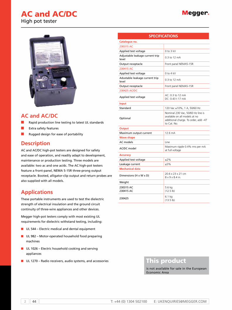
2 44 T: +44 (0) 1304 502100 E: [email protected]
AC and AC/DCHigh pot tester
SPECIFICATIONSCatalogue no.
230315 Ac
Applied test voltage 0 to 3 kV
Adjustable leakage current trip level
0.3 to 12 mA
output receptacle Front panel NEMA5-15R
230415 Ac
Applied test voltage 0 to 4 kV
Adustable leakage current trip level
0.3 to 12 mA
output receptacle Front panel NEMA5-15R
230425 Ac/Dc
Applied test voltageAC: 0.3 to 12 mADC: 0.43 t 17 mA
Input
standard 120 Vac ±10%, 1 A, 50/60 Hz
optional
Nominal 230 Vac, 50/60 Hz line is available on all models at no additional charge. To order, add –47 to Cat. No.
Output
maximum output current 12.6 mA
Wave shape
Ac models Line
Ac/Dc modelMaximum ripple 0.4% rms per mA at full voltage
Accuracy
Applied test voltage ±2%
Leakage current ±5%
Mechanical data
Dimensions (H x W x D)20.6 x 23 x 21 cm 8 x 9 x 8.4 in.
Weight
230315 Ac230415 Ac
5.6 kg(12.5 lb)
2304256.1 kg(13.5 lb)
AC and AC/DCn rapid production line testing to latest uL standards
n Extra safety features
n rugged design for ease of portability
DescriptionAc and Ac/Dc high-pot testers are designed for safety
and ease of operation, and readily adapt to development,
maintenance or production testing. Three models are
available: two ac and one ac/dc. The Ac high-pot testers
feature a front-panel, nEmA 5-15r three-prong output
receptacle. Booted, alligator-clip output and return probes are
also supplied with all models.
ApplicationsThese portable instruments are used to test the dielectric
strength of electrical insulation and the ground circuit
continuity of three-wire appliances and other devices.
megger high-pot testers comply with most existing uL
requirements for dielectric withstand testing, including:
n uL 544 – Electric medical and dental equipment
n uL 982 – motor-operated household food preparing
machines
n uL 1026 – Electric household cooking and serving
appliances
n uL 1270 – radio receivers, audio systems, and accessories This product is not available for sale in the European Economic Area

45 2WWW.mEggEr.com
AC and AC/DCHigh pot tester
ORDERING INFORMATIONProduct Order Code
Ac High-Pot Testers
0 to 3 kV 230315
0 to 4 kV 230415
Ac/Dc High-Pot Tester, 0 to 4 kV ac/5 kV dc 230425
standard non-resonant unit with 240 Vac input, 60 Hz operation, analog meters
686100-360W
included accessories
Test probes with alligator clips for ac models, includes one cat. no. 25507 high-voltage probeand one cat. no. 25136 return probe, 1.2 m[4 ft]; for ac/dc models, includes one cat. no. 25149 complete assembly, 1.2 m[4 ft]
Power cord 17032
instruction manual for 230315 and 230415 AVTm23-1J
instruction manual for 230425 AVTm23-4J
Product Order Code
optional accessories
Test probes with retractable tips, 1.2 m [4 ft]
High-voltage probe for ac models only 230315-2
return probe for ac models only 230315-3
High-voltage and return probe set for ac/dc model only
230425-2
Adapters, for conversion of output receptacles for use with twist-lock plugs
nEmA L5-15r twist lock 235300-1
nEmA L5-20r twist lock 235300-2
nEmA L5-30r twist lock 235300-4

2 46 T: +44 (0) 1304 502100 E: [email protected]
670025 series Capacitance and dissipation factor test sets
670025 seriesn Interference suppression circuits for testing in high-
voltage switchyards
n Automatic balancing of dissipation factor
n Direct readout of capacitance, dissipation factor and
watts dissipated
n Lightweight, compact design
DescriptionCapacitance and Dissipation Factor (C&DF) Test Sets are used
for evaluating the nature and quality of electrical insulation
materials and systems.
By measuring dissipation factor losses in electrical insulation,
these units can indicate the presence of contaminants,
fractures and punctures.
As part of a routine maintenance program, capacitance and
dissipation factor testing can aid in predicting potential
failure of deteriorating insulation.
The C&DF Test Sets include interference suppression circuits
that assure accurate measurements even under severe
interference or noise
ApplicationsThe test sets are used for testing high-voltage electrical
insulation systems at the power frequency by applying test
voltages up to 12 kV.
The purpose of the dissipation factor measurement of high-
voltage insulation is to find early signs of weakness in the
high-voltage insulation.
SPECIFICATIONS
Instrumentation Common to all test sets
Voltmeter and ammeter Digital readout with LED display
Ammeter
Accuracy ±(1% of reading +0.1 mA)
Resolution0.1 mA up to 200 mA; 1 mA above 200 mAAmmeter reads specimen current only.
Voltmeter accuracy ±(1% of reading +1 digit)
Resolution 10 V
Dissipation factor and watts/milliwatts
0 to 20% DF range
Operating temperature -20 ºC to +60 ºC (-4 ºF to +140 ºF)
Accuracy 0.01% DF
0 to 200% DF range
Accuracy ±(2% of reading + 0.05% DF)
Resolution 0.1% DF
Both positive and negative DF values are indicated automatically.Values up to 1200% DF can be measured by indirect methods.LO/HI equivalent milliwatts/watts dissipated in specimen.
Capacitance
Range0 to 220.000 pF in eight ranges;110/220/1100/2200/11,000/22,000/110,000/220,000 pF full scale
Accuracy
±(1% of reading + 2 pF) for ungrounded specimen test±(1% of reading + 6 pF) for grounded specimen test
Resolution 0.01% of range selected
Mechancial data
Dimensions (each unit)310 H X 510 W x 380 D mm(12.5 H x 19.5 W x 15 D in.)
Weight
2.5 kV unit 23 kg (51 lb)
12 kV measuring unit 22 kg (48 lb)
12 kV HV power unit 29 kg (63 lb)
Cables only 15 kg (34 lb)
2.5 kV test set
Input (specify one)
120 V, 60 Hz, 3 A continuous120 V, 50 Hz, 3 A continuous240 V, 60 Hz, 1.5 A continuous240 V, 50 Hz, 1.5 A continuous
Ouput
Voltage 0 to 2.5 kV ac, digital readout
Current 0 to 100 mA continuous
12 kV test set
Input (specify one)
120 V, 60 Hz, 10 A continuous 120 V, 50 Hz, 10 A continuous240 V, 60 Hz, 5 A continuous 240 V, 50 Hz, 5 A continuous
Specification continued
SPECIFICATIONS

47 2WWW.mEggEr.com
Instrumentation Common to all test sets
Voltmeter and Ammeter Digital readout with LED display
Ammeter
Accuracy ±(1% of reading + 0.1 mA)
Resolution0.1 mA up to 200 mA; 1 mA above 200 mAAmmeter reads specimen current only.
Voltmeter accuracy ±(1% of reading + 1 digit)
Resolution 10 V
Dissipation factor and watts/milliwatts
0 to 20% DF range
Operating temperature -4 ºF to +140 ºF (-20 ºC to +60 ºC)
Accuracy 0.01% DF
0 to 200% DF range
Accuracy ±(2% of reading + 0.05% DF)
Resolution 0.1% DF
Both positive and negative DF values are indicated automatically.Values up to 1200% DF can be measured by indirect methods.LO/HI equivalent milliwatts/watts dissipated in specimen.
Capacitance
Range0 to 220.000 pF in eight ranges;110/220/1100/2200/11,000/22,000/110,000/220,000 pF full scale
Accuracy
±(1% of reading +2 pF) for ungrounded specimen test±(1% of reading +6 pF) for grounded specimen test
Resolution 0.01% of range selected
ORDERING INFORMATIONProduct Order Code
2.5 kV capacitance and dissipation factor test set
120 V ac, 60 Hz 670025
120 V ac, 50 Hz 670025-44
220 V ac, 60 Hz 810130-2
240 V ac, 60 Hz 670025-45
240 V ac, 50 Hz 670025-47
12 kV capacitance and dissipation factor test set
120 V ac, 60 Hz 670065
120 V ac, 50 Hz 670065-44
240 V ac, 60 Hz 670065-45
240 V ac, 50 Hz 670065-47
12 kV extended range capacitance and dissipation
Factor test set
120 Vac, 60 Hz 670070
Product Order Code
120 Vac, 60 Hz 670070-44
120 Vac, 50 Hz 670070-45
240 Vac, 60 Hz 670070-45
240 Vac, 50 Hz 670070-47
Included accessories
2.5 kV unit
Line cord, ac
Transport case
CB-CHEK calibrator
Instruction manual
Optional accessories
Range extension adapter
For 120 V, 60 Hz operation 810132
For 240 V, 50 Hz operation 810132-1
Lead sets
1 m (3.3 ft) 810136-2
18 m (59.4 ft) 810136-3
Mechancial data
Dimensions (each unit)310 H X 510 W x 380 D mm (12.5 H x 19.5 W x 15 D in.)
Weight
2.5 kV unit 23 kg (51 lb)
12 kV measuring unit 22 kg (48 lb)
12 kV HV power unit 29 kg (63 lb)
Cables only 15 kg (34 lb)
Ouput
Voltage 0 to 12 kV ac, digital readout
Current
High Range to 5 kV: 0 to 200 mA continuous; 0 to 400 mA for 10 minLow Range to 10 kV: 0 to 100 mA continuous; 0 to 200 mA for 10 min
670025 series Capacitance and dissipation factor test sets

2 48 T: +44 (0) 1304 502100 E: [email protected]
Optional Accessoriesfor AC insulation testers
670600-1Capacitor kit includes carry case, TTR capacitor (left), and 2 reference capacitors (center). Also shown are 2 connectors (right)
670501Accessory kit includes mini bushing tap connectors, hot collar straps, temperature/humidity meter, .75” bushing tap connector, 1” bushing tap connector, “J” probe bushing tap connector, 3-ft non-insulating shorting leads, 6-ft non-insulating shorting leads.
670511Oil test cell is used for testing insulating fluids up to 10 kV.
36528Optional bar code wand for recording an alphanumeric test identification.
670550-1The optional Calibration Standard traceable to the NIST for quick operating or calibration checks of test set bridges calibrated in watts loss or in dissipation factor.

49 2WWW.mEggEr.com

3 50 T: + 44 (0) 1304 502100 E: [email protected]
Selection guide ........................................................................................... 51Technical information .................................................................................. 52DLRO200 200 A digital micro-ohmmeter .................................................... 53DLRO600 600 A ohmmeter ......................................................................... 54DLRO10HD 10 A digital ohmmeter ............................................................. 55KC100 wind turbine protection test lead ..................................................... 56DLRO10 and DLRO10X digital micro-ohmmeter .......................................... 57BT51 low resistance ohmmeter ................................................................... 58247000 series low resistance ohmmeter ...................................................... 59MjöLneR 200 micro-ohmmeter .................................................................. 62MjöLneR 600 micro-ohmmeter .................................................................. 64MOM2 micro-ohmmeter ............................................................................. 66MOM200 A micro-ohmmeter ..................................................................... 70MOM600A micro-ohmmeter ...................................................................... 72 MOM690 micro-ohmmeter ......................................................................... 74Optional accessories .................................................................................... 77
The operation of electrical equipment depends on the controlled flow of current within the design parameters of a given piece of equipment. Measuring low resistance helps identity resistive elements that have increased above acceptable levels.
DLRO10 micro-ohmmeters have been designed primarily for the traction and transportation industry.
MOM and MJöLNER micro-ohmmeters were designed for switchyards.
In practice, you should check products from both ranges to see which suits your applications.
Low Resistance Ohmmeters
3

51 3WWW.mEggER.com
SELECTION GUIDE
DLRO 200
DLRO 600
DLRO 10HD
DLRO10/ 10X
BT51 24700 Mjölner 200
Mjölner 600
MOM2 MOM 200
MOM 600
MOM 690
RS232 n n n
Mains power source n n n n n n n n n
Rechargeable battery power source
n n n n n
Forward and reverse measurement
n n n
Inductive mode n n n
IP54 ingress protection with case open
n
User selectable test limits
10X only
n
Designed for industrial and traction industries
n n n n n n n n n n n n
Designed for switchyards n n n n n n n n
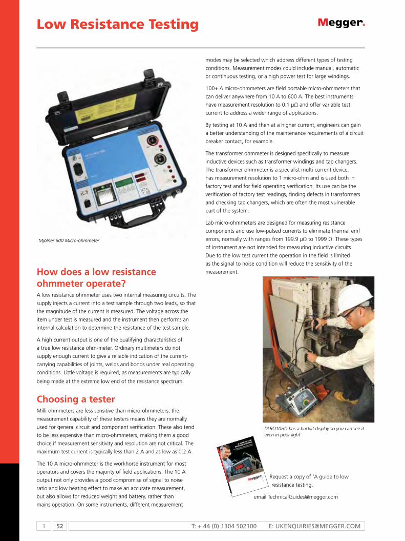
3 52 T: + 44 (0) 1304 502100 E: [email protected]
Low Resistance Testing
How does a low resistance ohmmeter operate?A low resistance ohmmeter uses two internal measuring circuits. The
supply injects a current into a test sample through two leads, so that
the magnitude of the current is measured. The voltage across the
item under test is measured and the instrument then performs an
internal calculation to determine the resistance of the test sample.
A high current output is one of the qualifying characteristics of
a true low resistance ohm-meter. Ordinary multimeters do not
supply enough current to give a reliable indication of the current-
carrying capabilities of joints, welds and bonds under real operating
conditions. Little voltage is required, as measurements are typically
being made at the extreme low end of the resistance spectrum.
Choosing a testerMilli-ohmmeters are less sensitive than micro-ohmmeters, the
measurement capability of these testers means they are normally
used for general circuit and component verification. These also tend
to be less expensive than micro-ohmmeters, making them a good
choice if measurement sensitivity and resolution are not critical. The
maximum test current is typically less than 2 A and as low as 0.2 A.
The 10 A micro-ohmmeter is the workhorse instrument for most
operators and covers the majority of field applications. The 10 A
output not only provides a good compromise of signal to noise
ratio and low heating effect to make an accurate measurement,
but also allows for reduced weight and battery, rather than
mains operation. On some instruments, different measurement
modes may be selected which address different types of testing
conditions. Measurement modes could include manual, automatic
or continuous testing, or a high power test for large windings.
100+ A micro-ohmmeters are field portable micro-ohmmeters that
can deliver anywhere from 10 A to 600 A. The best instruments
have measurement resolution to 0.1 µΩ and offer variable test
current to address a wider range of applications.
By testing at 10 A and then at a higher current, engineers can gain
a better understanding of the maintenance requirements of a circuit
breaker contact, for example.
The transformer ohmmeter is designed specifically to measure
inductive devices such as transformer windings and tap changers.
The transformer ohmmeter is a specialist multi-current device,
has measurement resolution to 1 micro-ohm and is used both in
factory test and for field operating verification. Its use can be the
verification of factory test readings, finding defects in transformers
and checking tap changers, which are often the most vulnerable
part of the system.
Lab micro-ohmmeters are designed for measuring resistance
components and use low-pulsed currents to eliminate thermal emf
errors, normally with ranges from 199.9 µΩ to 1999 Ω. These types
of instrument are not intended for measuring inductive circuits.
Due to the low test current the operation in the field is limited
as the signal to noise condition will reduce the sensitivity of the
measurement.
Request a copy of ‘A guide to low
resistance testing.
email [email protected]
Mjölner 600 Micro-ohmmeter
DLRO10HD has a backlit display so you can see it even in poor light

53 3WWW.mEggER.com
DLRO200Digital micro-ohmmeter
See page 61
DLRO200n Test currents from 10 A to 200 A d.c.
n 0.1 μW best resolution
n on-board memory for up to 300 test results and notes
n RS232 port to download stored results or for real time output to a printer
n Supplied complete with 5 m test leads and download software
n Smooth, continuous applied current eliminates magnetic transients capable of inductively tripping breaker controls (115 V version)
Descriptionmegger DLRo200 measures resistances between 0.1 μW and 1 W, at high currents. This versatile instrument can provide test currents from 10 A up to 200 A subject to the load resistance and supply voltage. A large liquid crystal display provides all the information needed to perform a test; all test parameters and measurement results are displayed.
The unique design allows the weight and size of DLRo200 to be kept to a minimum; the instrument weighs less than 15 kg. This small size makes DLRo200 equally at home in the workshop, on the production floor or in the field. The high current capability and compact design make DLRo200 suitable for testing circuit breaker contacts, switch contacts, busbar joints or other
applications where high current is needed.
measurement range 0.1 μW to 999.9 mW (subject to supply voltage and leads used)
Accuracy:VoltagecurrentResistance
±0.5% ± 0.1 mV±0.5% ± 0.1 ABetter than 1% from 300 μW to 100 mWBetter than ±2% from 100 μW to 300 μW
maximum continuous test time More than 600 seconds or 10 minutes at 200 A @ 20 ºC ambient
Power supply
Power supply for DLRo200for full output (unsmoothed d.c.)
100 V to 265 V 50/60 Hz with a load less than 19 mW (supply >207 V rms), or 11 mW (115 V rms) including current leads
Power supply for DLRo200-115 V for full output (additional smoothing)
100 V to 130 V 50/60 Hz with a load less than 11 mW including current leads
Test modes Manual, Auto, Continuous
Test time 10 seconds nORMAL /AUTO mode Refreshed every 2 seconds in COnTInUOUS mode
Display Large, high resolution backlit liquid crystal display
WarningsCurrent flowing - LeDOther warnings are shown on the lcd display
Data transfer Real time or batch download via RS232 using Download Manager software
Storage capacity 300 result sets and memo, battery backed for 10 years
memo field 160 characters max
Test current:RangeAccuracy
10 A to 200 A d.c. ±2% ±2 A
Voltmeter input:ImpedanceHum rejection
>200 kW5 V rms 50 Hz/60 Hz
Environmental
operation temperature -10 ºC to +50 ºC
Storage temperature -25 ºC to +65 ºC
calibration 20 ºC
co-efficient <0.05% per ºC
max. humidity 95% RH non-condensing
max. altitude 2000 m
Mechanical data
Dimensions (H x W x D) 410 mm x 250 mm x 270 mm
Weight 14.5 kg (excluding test leads)
SPECIFICATIONS
ORDERING INFORMATIONProduct Order Code
Standard versions with test leads
DLRo200 high current digital low resistance ohmmeter (QWERTY keyboard)
DLRo200-EN
DLRo200 high current digital low resistance ohmmeter (French AZERTY keyboard)
DLRo200-FR
DLRo200-115 high current digital low resistance ohmmeter 115 V with additional Dc output smoothing (QWERTY keyboard)
DLRo200-115
Versions without test leads
DLRo200 high current digital low resistance ohmmeter (QWERTY keyboard)
DLRo200-EN-NLS
DLRo200 high current digital low resistance ohmmeter (French AZERTY keyboard)
DLRo200-FR-NLS
DLRo200-115 high current digital low resistance ohmmeter 115 V with additional output smoothing (QWERTY keyboard)
DLRo200-115-NLS
Included accessories for DLRo200-EN
5 m lead set set comprising 2 x 50 mm 2 current leads with clips and 2 potential leads with clips
6220-755
ORDERING INFORMATION continuedProduct Order Code
Included accessories for DLRo200-115
5 m lead set in bag comprising 2 x 25 mm2 current leads with clamps and 2 x potential leads with clips
6220-787
Included accessories for ALL DLRo200 versions
Download manager 6111-442
User guide on cD-Rom 6172-763
RS232 download cable 25955-025
Quick start guide (English) 6172-782
Quick start guide (French) 6172-783
Warranty card 6170-618
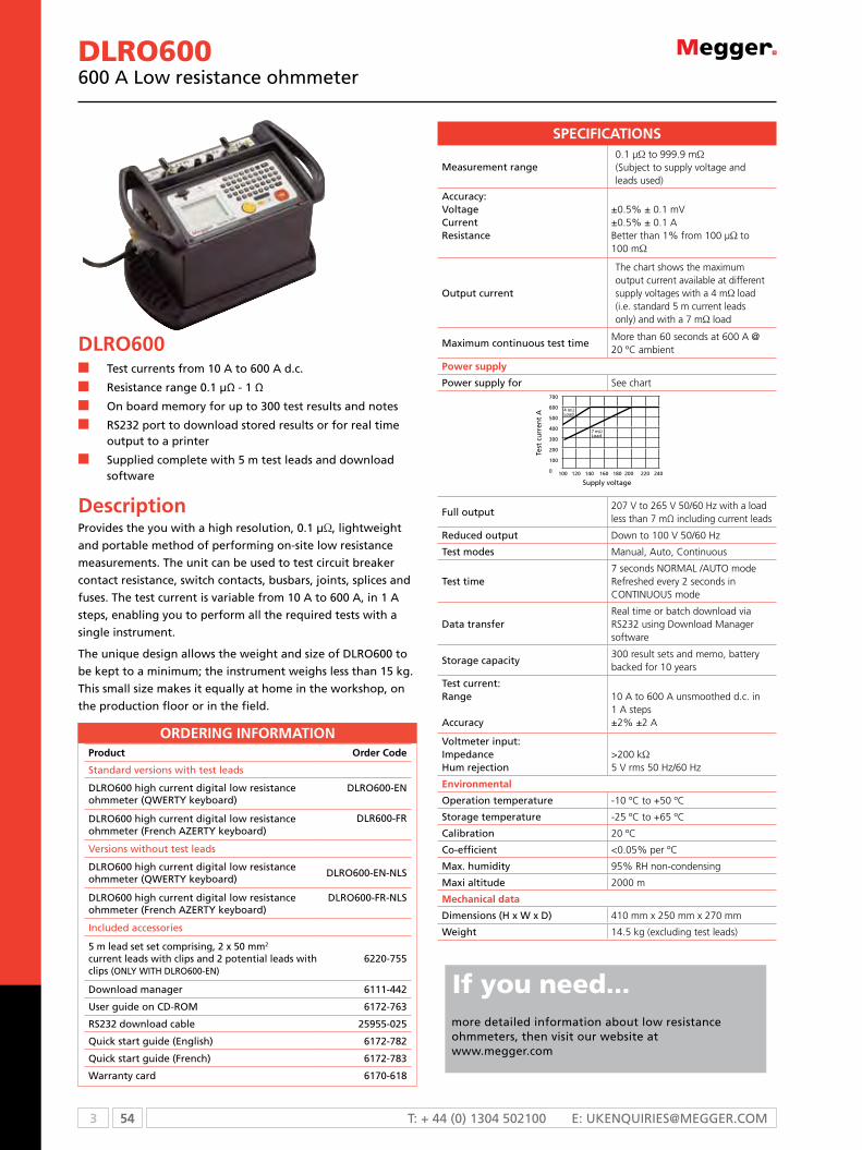
3 54 T: + 44 (0) 1304 502100 E: [email protected]
DLRO600600 A Low resistance ohmmeter
DLRO600n Test currents from 10 A to 600 A d.c.
n Resistance range 0.1 µΩ - 1 Ω
n on board memory for up to 300 test results and notes
n RS232 port to download stored results or for real time output to a printer
n Supplied complete with 5 m test leads and download software
DescriptionProvides the you with a high resolution, 0.1 µW, lightweight
and portable method of performing on-site low resistance
measurements. The unit can be used to test circuit breaker
contact resistance, switch contacts, busbars, joints, splices and
fuses. The test current is variable from 10 A to 600 A, in 1 A
steps, enabling you to perform all the required tests with a
single instrument.
The unique design allows the weight and size of DLRo600 to
be kept to a minimum; the instrument weighs less than 15 kg.
This small size makes it equally at home in the workshop, on
the production floor or in the field.
ORDERING INFORMATIONProduct Order Code
Standard versions with test leads
DLRo600 high current digital low resistanceohmmeter (QWERTY keyboard)
DLRo600-EN
DLRo600 high current digital low resistanceohmmeter (French AZERTY keyboard)
DLR600-FR
Versions without test leads
DLRo600 high current digital low resistanceohmmeter (QWERTY keyboard)
DLRo600-EN-NLS
DLRo600 high current digital low resistanceohmmeter (French AZERTY keyboard)
DLRo600-FR-NLS
Included accessories
5 m lead set set comprising, 2 x 50 mm2 current leads with clips and 2 potential leads with clips (oNLY WITH DLRo600-EN)
6220-755
Download manager 6111-442
User guide on cD-Rom 6172-763
RS232 download cable 25955-025
Quick start guide (English) 6172-782
Quick start guide (French) 6172-783
Warranty card 6170-618
If you need...more detailed information about low resistance ohmmeters, then visit our website at www.megger.com
measurement range 0.1 μW to 999.9 mW(Subject to supply voltage and leads used)
Accuracy:VoltagecurrentResistance
±0.5% ± 0.1 mV±0.5% ± 0.1 ABetter than 1% from 100 μW to 100 mW
output current
The chart shows the maximum output current available at different supply voltages with a 4 mW load (i.e. standard 5 m current leads only) and with a 7 mW load
maximum continuous test timeMore than 60 seconds at 600 A @ 20 ºC ambient
Power supply
Power supply for See chart
Full output207 V to 265 V 50/60 Hz with a load less than 7 mΩ including current leads
Reduced output Down to 100 V 50/60 Hz
Test modes Manual, Auto, Continuous
Test time 7 seconds nORMAL /AUTO mode Refreshed every 2 seconds in COnTInUOUS mode
Data transferReal time or batch download via RS232 using Download Manager software
Storage capacity300 result sets and memo, battery backed for 10 years
Test current:Range
Accuracy
10 A to 600 A unsmoothed d.c. in 1 A steps ±2% ±2 A
Voltmeter input:ImpedanceHum rejection
>200 kW5 V rms 50 Hz/60 Hz
Environmental
operation temperature -10 ºC to +50 ºC
Storage temperature -25 ºC to +65 ºC
calibration 20 ºC
co-efficient <0.05% per ºC
max. humidity 95% RH non-condensing
maxi altitude 2000 m
Mechanical data
Dimensions (H x W x D) 410 mm x 250 mm x 270 mm
Weight 14.5 kg (excluding test leads)
SPECIFICATIONS
100 120 140 160 180 200 220 240
700
600
500
400
300
200
100
0
4 mWLoad
7 mWLoad
Test
cu
rren
t A
Supply voltage

55 3WWW.mEggER.com
DLRO10HD10 A Digital low resistance ohmmeter
Resistance/current ranges
The green resistance ranges on the keypad indicate low output power (<0.25 W) outputs. Red ranges indicate higher 2.5 W (1 A) and 25 W (10 A) power outputs
measurement range 0.1 μW to 2500.0 Wmanual range selection
Display and battery
Display size/typeLCD, main 5 digit + 2 x 5 digit secondary displays
Battery type 6 V, 7Ah sealed lead acid
Voltage input range 90 - 264 V, 50-60 Hz
charge time 8 hours
Backlight LeD backlight
Battery life 1000 Auto (3 sec) tests
Auto power down 300 s
mode selection Rotary switch
Range selection Rotary switch
Reference conditions 20 °C ±3 °C
Environmental
Temperature co-efficient < 0.01% per ºC, from 5 ºC to 40 ºC
Storage temperature and humidity
-25 °C to +60 °C, <90% RH
operating temperature and humidity
-10 °C to +50 °C <90% RH
Noise rejection
Less than 1% ±20 digits additional error with 100 mV peak 50/60 Hz on the potential leads. Warning will show if hum or noise exceeds this level.
maximum lead resistance100 mW total for 10 A operation irrespective of battery condition
IP rating IP65 case closed, IP54 open
maximum altitude 2000 m to full safety specifications
SPECIFICATIONS
ORDERING INFORMATIONProduct Order Code
DH2 right angle duplex handspikes (1) 6 m 6111-023
DH3 right angle duplex handspikes (1) 9 m 6111-024
Straight duplex handspikes (2) heavy duty with fixed contacts 2 m5.5 m9 m
242002-7242002-18242002-30
Duplex heavy duty 5 cm c-clamps(2) 2 m5.5 m9 m
242004-7242004-18242004-30
Duplex handspikes with replaceable needle points
2 m 242003-7
Duplex 1.27 cm Kelvin clips(2) gold plated 2 msilver plated 2 m
241005-7242005-7
Duplex 3.8 cm Kelvin clips(2) 2 m5.5 m9 m
242006-7242006-18242006-30
Single leads
Single handspike (1) for potential measurement2 m5.5 m9 m
242021-7242021-18242021-30
current clip (1) for current connections2 m5.5 m9 m
242041-7242041-18242041-30
Product Order Code
DLRo10HD low resistance ohmmeter 1000-348
Included accessories
DH4 duplex handspike 1.2 m 6111-503
Test lead pouch (lid mounted) 1000-036
DLRo10HD user guide cD 2000-869
Warranty book 6170-618
optional accessories
calibration shunt,10 W, current rating 1 mA 249000
calibration shunt, 1 W, current rating 10 mA 249001
calibration shunt, 100 mW current rating 1 A 249002
calibration shunt, 10 mW current rating 10 A 249003
certificate of calibration for shunts, NIST cERT-NIST
Replacement tips for DH4, DH5 and DH7 handspikes
Needle point 25940-012
Serrated end 25940-014
optional test leads at extra cost
Duplex leads
DH5 straight duplex handspikes (2) one has indicator lights, 2.5 m
6111-517
DH7 duplex handspikes (2) suitable for working on 600 V systems, 2.5 m
1001-035
Duplex handspikes (2) with spring loaded helical contacts, 2 m
242011-7
Duplex handspikes (2) 2.5 m 6111-022
DLRO10HDn High or low output power selection for condition diagnosisn Rechargeable battery or line power supply, continuous operation, even with dead batteryn 10 A for 60 seconds, less time waiting to cool, good for charging inductancen High input protection to 600 V, inadvertent connection to line or UPS voltage will not blow a fusen Rotary switch selects one of five test modes, including auto start on connection, giving ease of usen Backlit display
DescriptionAugmenting megger’s DLRo10 and 10X range the DLRo10HD combines ultimate simplicity of operation with a rugged IP65 case designed for stable ground and bench operation.
The DLRo10HD measures low resistance values in applications ranging from railways and aircraft to resistance of components in industry.

3 56 T: + 44 (0) 1304 502100 E: [email protected]
KC series test leadsWind turbine lightning protection test lead sets
DescriptionThe Kc series of test leads provides a complete and convenient solution to the problem of finding reliable test leads that are long enough for testing the continuity of lightning protection conductors in wind turbines.
Kc-series wind turbine test leads are available in 100 m, 50 m and 30 m versions that are suitable for use on site or in the manufacturing plant. All lead set versions are 10 A rated.
The lead sets consist of two test leads. The first is a 5 m cable fitted with a duplex handspike for probing the lightning receptors on the tips of the turbine blades. The second cable is either a 30 m, 50 m or 100 m cable, fitted with a large robust Kelvin clip, specially designed to offer ease of use while providing the consistently reliable connections needed to ensure accurate and repeatable test results.
The long cable is wound onto a high quality, robust cable reel fitted with a friction brake to avoid tangles whilst paying out.
ORDERING INFORMATIONProduct Order Code
Kc100 Kelvin lead kit (1 x 100 m / 1 x 5 m) 1000-809
Kc50 Kelvin lead kit (1 x 50 m / 1 x 5 m) 1001-248
Kc30 Kelvin lead kit (1 x 30 m / 1 x 5 m) 1001-249
KC series test leadsn Developed in conjunction with a leading manufacturer
of wind turbines
n Allows easy and reliable measurement of lightning
protection circuit resistance of wind turbines
n Available in three lengths; 30 m, 50 m and 100 m to suit
both manufacturing and maintenance applications
n Long cable fitted on strong metal framed cable reel
n cable reel fitted with friction brake to avoid tangles
when paying out cable
If you need...other test leads for your low resistance ohmmetersee page 77
KC test leads used with a DLR010 HD for testing continuity of wind turbines

57 3WWW.mEggER.com
DLRO10 and DLRO10XDigital micro-ohmmeter
DLRO10 and DLRO10Xn Auto current reversal cancels standing emfs
n Protected to 600 V
n Automatically detects continuity in potential and current connections
n multiple operating modes including fully automatic
n Alpha-numeric keypad for entering test notes (DLRo10X)
n User selectable high and low limits (DLRo10X)
n Printer output and memory (DLRo10X)
DescriptionDLRo10 and DLRo10X are fully automatic instruments, selecting the most suitable test current up to 10 A d.c. to measure resistance from 0.1 μW to 2000 W, on one of seven ranges.
For users who want more control over the measurement process, DLRo10X uses a menu system controlled by a two-axis paddle to allow the user to manually select the maximum test current. DLRo10X also adds real time download of results and on board storage for later download to a Pc.
Both instruments are built into a strong, lightweight case that is equally at home in the field or in the laboratory. Light enough to be worn around the neck, they are small enough to
be taken into areas that were previously too small to access.
maximum lead resistance 100 mW total for 10 A operation irrespective of battery condition
Voltmeter input impedance > 200 kW
Hum rejection
Less than 1% ± 20 digits additional error with 100 mV peak 50/60 Hz on the potential leads Warning will show if hum or noise exceeds this level
Display
DLRo10 Seven segment display
DLRo10X LCD display
Battery
capacity 7 Ah niMH rechargeable
LifeTypically 1000 x 10 A tests before recharge
RechargeVia external 90 V - 260 V 50/60 Hz charger or from 12 to 15 V d.c. supply
charging time2.5 hours to 90% capacity, 4 hours for full charge
Environmental
TemperatureOperation +5 °C to +45 °C at full specification -10 °C to +50 °C at reduced accuracy
Storage -30 °C to +70 °C
calibration 20 °C
co-efficient <0.01% per °C from 5 °C to 40 °C
Standard charging 0 °C to +45 °C
Fast charging +10 °C to +45 °C
HumidityMax 90% RH @ 40 °C non-condensing
AltitudeMax 2000 m to full safety specifications
Mechanical data
Dimensions (H x W x D) 220 mm x 100 mm x 237 mm
Weight 2.6 kg including battery module
SPECIFICATIONS
ORDERING INFORMATIONProduct Order Code
certificate of calibration for shunts, NIST cERT-NIST
Replacement tips for DH4, DH5 and DH6 handspikes
Needle point 25940-012
Serrated end 25940-014
optional test leads at extra cost
Duplex leads
DH5 straight duplex handspikes (2) one has indicator lights, 2.5 m
6111-517
DH6 duplex handspikes (2) suitable for working on 600 V systems, 2.5 m
6111-518
Duplex handspikes (2) with spring loaded helical contacts
2 m2.5 m5.5 monly 1 lead supplied 6 m9 m
242011-76111-022
242011-186111-023
242011-30
Straight duplex handspikes (2) heavy duty with fixed contacts
2 m5.5 m9 m
242002-7242002-18242002-30
Product Order Code
DLRo10 digital low resistance ohmmeter 6111-428
DLRo10X digital low resistance ohmmeter 6111-429
Included accessories
7 Ah NimH battery module
DH4 duplex handspikes (2), one with indicator lights 1.2 m
6111-503
Battery charger for operation from 115/230 V 50/60 Hz supply
6280-333
cigar lighter adapter for battery charging 6280-332
User guide 6172-473
Warranty book 6170-618
optional accessories at extra cost
carrying case for DLRo10/10X and all standard accessories
6380-138
carrying case for optional lead sets 18313
calibration shunt,10 W, current rating 1 mA 249000
calibration shunt, 1 W, current rating 10 mA 249001
calibration shunt, 100 mW current rating 1 A 249002
calibration shunt, 10 mW current rating 10 A 249003

3 58 T: + 44 (0) 1304 502100 E: [email protected]
SPECIFICATIONS
Ranges2000 mW, resolution 1 mW 20,00 mW, resolution 0,01 mW
Test current2 A nominal, with up to 2 W across the C terminals
Accuracy(0 °C to 50 °C) ±1% of reading ±2 digits
Display 3½-digit LeD display
Environmental
operating temperature 0 °C to 50 °C
Storage -20 °C to +50 °C
Relay protection for up to 240 V mains supply applied from C1/Pl to C2/P2
100 mA (T) fuse, 20 x 5 mm, ceramic (for charging circuit)
Power supply
4 Ah capacity niCad rechargeable cells with internal charging unit
normal charging time of 10 hours on 240 V, 50 Hz mains supply
Mechanical data
Dimensions (H x W x D) 245 mm x 344 mm x 158 mm
Weight 4.5 kg
SPECIFICATIONS
BT51n High test current
n Four terminal measurement
n Two measuring ranges (2000 mW and 20,000 mW) and maximum resolution of 0,01 mW
n Protected against inadvertent connection to the mains supply
DescriptionThe BT51 low resistance ohmmeter makes measurements by
passing a current through the conductor under test and also
monitoring the voltage across it. The test current is limited by
a simple current limiting circuit and is measured by monitoring
the voltage across a resistor. The test current is maintained
at a nominal 2 A, and as the measurement is ratiometric, the
reading is unaffected by any current variations.
Instruments that measure low resistance accurately and give
the result directly are invaluable in many applications.
The BT51 is a stable, accurate, reliable, low resistance
ohmmeter suited to both precision laboratory applications
and to applications in the field.
ORDERING INFORMATIONProduct Order Code
Low resistance ohmmeter (240 V operation) BT51
Low resistance ohmmeter (120 V operation) BT51/120
Included accessories
Supply lead for battery charger 25424-860
Duplex handspikes with 2,5 m test leads 6111-022
operating instruction book 6170-921
optional accessories
Test leads with duplex hand spikes 6,0 m 6111-023
Test leads with duplex hand spikes 9,1 m 6111-024
Four terminal lead set with clip connectors 6110-220
Test lead with single hand spikes, 1,8 m 6130-516
Accessory pouch, leather 6430-193
BT51Low resistance ohmmeter
If you need a...micro-ohmmeter designed for switchyards, see our mJÖLNER range from page 62

59 3WWW.mEggER.com
247000 seriesLow resistance ohmmeter
247000n Resolution to 0.1 μΩ on 599.9 μΩ range
n Standard accuracy of ±0.25%
n Digital readout
DescriptionLow resistance ohmmeters are a family of highly accurate
instruments that provide a simple, practical and reliable
means of making low-resistance tests in the field. They also
are ideal for production quality control.
They operate on the four-wire measurement principle,
thus eliminating lead and contact resistances. With basic
accuracies of ±0.25% and resolution down to 0.1 μΩ, they are
nonetheless designed to be rugged and portable for use at
the job site. A variety of optional test leads and calibration
resistance standards are offered for use with low resistance
ohmmeters.
General-purpose low resistance ohmmeters
Two models specially designed for general-purpose testing
applications are available.
Each provides up to 10 amperes of test current for measuring
resistances to 60 ohms with 1 μΩ resolution and ±0.25%
accuracy.
Dual-Pak general purpose model, Cat. No. 247000
This battery-powered unit features separate measuring and
charger modules for maximum portability. The charger can be
left in the shop, and the measuring module taken to the job
site.
It weighs less than 3.6 kg (8 lbs) and provides hours of testing.
Single-Pak general purpose model, Cat. No. 247001
This compact instrument packages measuring circuits,
rechargeable batteries and charger in one self-contained unit.
Ruggedly built to handle the most demanding field
applications, the Single-Pak is housed in a tough Noryl® case
with hinged, removable lid and carrying handle.
It also includes captive wing nuts.
Single-Pak/low range model, Cat. No. 247000
This model provides an extra range, 0 to 599.9 μΩ, for
applications requiring 0.1 μΩ resolution. It also features a
current-reversing switch to average out any voltage offset in
the test sample. captive wing nuts are also standard.
Low range/high current models, Cat. No. 247100 and 247101
These instruments are used when a continuous test current of
100 amperes is required. They include a separate 100 ampere
current supply module with a modified standard battery-
powered 10 ampere system.
These combinations provide a sixth range, 0 to 599.9 μΩ, with
the 100 ampere current. For 100 ampere measurements, an
interconnecting cable from the 100 ampere current supply
module is plugged into a special receptacle on the measuring
module.
When the 100 ampere range is not used, a jumper plug is
inserted in place of the interconnecting cable.
This feature allows the measuring module to be used as a
standard battery-powered, 10 A instrument.
cat. No. 247100 meets ANSI c37.09, test procedure for Ac
high voltage circuit breakers.

3 60 T: + 44 (0) 1304 502100 E: [email protected]
SPECIFICATIONS
Cat. No. Resistance range Resolution Current Accuracy Power sourceDimensions(H x W x D)
Weight
24700 - Dual Pak
0-5.999 mΩ0-59.99 mΩ0-599.9 mΩ 0-5.999 Ω 0-59.99 Ω
1 µΩ10 µΩ0.1 mΩ1 mΩ10 mΩ
10 A1 A100 mA10 mA1 mA
(0.25% reading + 1 lsd)
Rechargeable batteries with separate charger
20 x 23 x 20 cm(8 x 9 x 8 in.)
5.6 kg(12.25 lb)
247001 - Single Pak
0-5999 mΩ0-59.99 mΩ0-599.9 mΩ 0-5.999 Ω 0-59.99 Ω
1 µΩ10 µΩ0.1 mΩ1 mΩ10 mΩ
10 A1 A100 mA10 mA1 mA
(0.25% reading + 1 lsd)
Rechargeable batteries with internal charger
30 x 16 x 25 cm(12 x 6 x 10 in.)
5.5 kg(12 lb)
247002 - Single Pak, low range
0-599.9 mΩ0-5.999 mΩ0-59.99 mΩ 0-5.999 Ω 0-59.99 Ω
0.1 µΩ1 µΩ10 µΩ1 mΩ10 mΩ
10 A10 A1 A10 mA1 mA
(0.3% reading + 1 lsd)
Rechargeable batteries with internal charger
30 x 16 x 25 cm(12 x 6 x 10 in.)
5.5 kg(12 lb)
247100247120 - Power Pak, low range
0.599.9 mΩ 0.1 µΩ 100 A(0.5% reading + 2 lsd)
Line operated supply33 x 20 x 25 cm(13 x 8 x 10 in.)
9.3 kg(20 lb)
247101 - Higher ranges measuring modules 247000-3 or 247001-3
0-5.999 mΩ*0-59.99 mΩ0-599.9 mΩ0-5.999 Ω0-59.99 Ω or 0.5999 Ω*
1 µΩ10 µΩ0.1 mΩ1 mΩ10 mΩ
10 A1 A100 mA10 mA1 mA
(0.25% reading + 1 lsd) Rechargeable batteries
with separate charger or internal charger
Dual-Pak units20 x 23 x 20 cm(8 x 9 x 8 in.)
Single-Pak30 x 16 x 25 cm(12 x 6 x 10 in.)
5.5 kg(12 lb)
247100 consists of 247000-3 Dual-Pak & 247120 100 ampere Power Supply247101 consists of 247001-3 Single-Pak & 247120 100 ampere Power Supply*Alternate range ID for lower range.
SPECIFICATIONS
247000 seriesLow resistance ohmmeter

61 3WWW.mEggER.com
ORDERING INFORMATIONProduct Order Code
Instrument carrying case for cat. No. 247001, 247002
218748
Lead carrying case 18313
Field test shunt, 10 Ω, current rating 0.001 A 249000*
Field test shunt, 1 Ω, current rating 0.01 A 249001*
Field test shunt, 0.1 Ω current rating 1 A 249002*
Field test shunt, 0.01 Ω current rating 10 A 249003
Field test shunt, 0.001 Ω current rating 100 A 249004
Field test, 0.0001 Ω current rating 500 A 249005
certificate of calibration, NST cERT-NIST
*Furnished with protective shield
Product Order Code
DLRo® Digital low resistance ohmmetersDual Pak, battery-operated (10 A)
247000
Single Pak, battery operated (10 A) 247001
Single Pak/low range, battery-operated (10 A) 247002
Low range/high current, line- andbattery-operated (100 A)
247100 or 247101
Included accessories
Line cord, where applicable 17032
Instruction manual AVTm24-1J
optional accessories
Test leads See chart
100 ampere current supply for cat. No. 247000-3 and 247001-3
247120
100 A adapter plug for cat. No. 247000 and 247001 only
Add -3
Input voltage protection for cat. No. 247000, 247001 and 247002 only
Add -11
230 V (nominal), 50/60 Hz operation Add -47
Instrument carrying case for cat. No. 247000 218746
Type TerminationMaximum test current
Length Cat. No.
Potential Handspikes n/A2 m (7 ft)5.5 m(18 ft)9 m (30 ft)
242021-7242021-18242021-30
current
Terminal clips 10 A2 m (7 ft)5.5 m (18 ft)9 m (30 ft)
242041-7242041-18242041-30
Heavy duty clamps
100 A***5 m (16 ft)8 m (26 ft)
242144-16242144-26
Individual test leads
TerminationMaximum test current
Length Cat. No.
Helical hand Spikes with spring points
20 A 10 A
2 m (7 ft)5.5 m (18 ft)9 m (30 ft)
242011-7242011-18242011-30
Helical hand Spikes with spring points and current pushbutton switch
10 A 5.5 m (18 ft) 242009-18
Heavy duty Fixed point Handspikes
10 A2 m (7 ft)5.5 m (18 ft)9 m (30 ft)
242002-7242002-18242002-30
Replaceable Needle point
10 A 2 m (7 ft) 242003-7
2 in. (5 cm) Heavy duty c clamps
10 A2 m (7 ft)5.5 m (18 ft)9 m (30 ft)
242004-7242004-18242004-30
4 in. (10 cm) Heavy duty c clamps
100 A***5 m (16 ft)
8 m (26 ft)
242104-2-16
242104-2-26
0.5 in. (1.3 cm) Kelvin clips
10 A 2m (7 ft)241005-7*242005-7**
Duplex test leads
247000 seriesLow resistance ohmmeter

3 62 T: + 44 (0) 1304 502100 E: [email protected]
MJÖLNER200micro-ohmmeter
MJöLNER200n Fully automatic testing - micro-processor controlled
n Safe test – Dualground™ and Remote control
n True Dc – ripple free current
n Lightweight suitcase – withstands the impact of water,
dust or sand
n Built in thermal printer
n Pc interface connection
DescriptionThe mJÖLNER™200 is designed to measure the resistance of circuit breaker contacts, bus-bar joints, contact elements in bus-bars and other high-current links. This product is designed with safety, ease of use and versatility in mind.
The micro-ohmmeter can be used anywhere to measure a low resistance value with high accuracy. It conducts true Dc ripple free current testing of bus bars, circuit breakers, fuses, etc. High current capability, up to 200 A Dc – the user avoids problems with incorrect test results due to low test current when testing high current devices such as circuit breakers.
mJÖLNER200 can make measurements using the Dualground™ method. This means that the test object will be grounded on both sides throughout the test giving a safer, faster and easier workflow. The lightweight and rugged suitcase design makes mJÖLNER200 an excellent choice when you need a portable solution in the field. With the case closed, the product can withstand the impact of water, dust or sand – it even floats.
optional accessories are a remote control and mJÖLNER Win Pc software that is compatible with IPS–cEBEX and has export functions for tables to microsoft® Excel®.
ApplicationsmJÖLNER 200 test system is designed to serve a number of applications. The most common are contact resistance measurements of low-, medium- and high-voltage breakers and also at bus-bar joints, and other high current links.
The contact resistance measurements concerning breaker testing are particularly called for in the following standards: ANSI c37.09-1979 (5.14), IEc 1208 and IEc 694 (6.4).
If the contact resistance is too high this will lead to power loss and temperature rise, which often leads to serious trouble. To avoid such problems, it is necessary to check the resistance at regular intervals.
The following table demonstrates how important low resistance is at high currents:
Current Contact resistance Power loss
10 kA 1 mΩ 100 kW
10 kA 0.1 mΩ 10 kW
1 kA 1 mΩ 1 kW
1 kA 0.1 mΩ 100 W
At 10 kA a contact with the resistance 0.1 mΩ gives a power loss of 10 kW. This power loss in one single point will definitely confer a temperature rise, which may result in overheating and possibly premature failure.
If you need a...low resistance ohmmeter designed for thetransportation industries see our DLRo range from page 53

63 3WWW.mEggER.com
SpecificationsSpecifications are valid at nominal input voltage and an ambient temperature of +25 °C, (77 °F). Specifications are subject to change without notice.
EnvironmentApplication field For use in high-voltage substations
and industrial environments.
Temperature
Operation -20 °C to +50 °C (-4 °F to +122 °F)
Storage -40 ºC to +70 ºC (-40 °F to +158 °F)
Relative humidity %RH 5%-95%, non condensing
CE-markingEMC 2004/108/eC
LVD 2006/95/eC
GeneralMains voltage 100 - 120, 200 - 240 V AC, 50 / 60 Hz
Power consumption (max) 39 A at 100 V, 18 A at 230 V
Protection Thermal fuses, Software
Dimensions 480 x 350 x 170 mm (19” x 13.7” x 6.7”)
Weight 8.5 kg (18.7 lbs)
Measurement sectionMeasuring range 0 – 999.9 mΩ
Resolution 0.1 μΩ below 1.0 mΩ 1 μΩ below 10 mΩ 10 μΩ below 100 mΩ 100 μΩ below 1000 mΩ
Inaccuracy, 50 – 600 A, 10 - 40 ºC, R < 1 mΩ
Typ ±0.3 μΩ, Max. ±2 μΩ
Outputs DC+ / COMRange 5 – 200 A DC (steps of 1 A)
Output voltage (max) 5.25 V DC at 200 A Ripple ptp <2% (0 to +50 °C)
OUTPUT 100 μV/A
Shunt output From internal shunt 60 mV at 200 A
Inaccuracy ±1%
InputsSENSE Max. 20 V between terminals and
to protective earth (ground).
INPUT DC current clamp
Max. 20 V between terminals and to protective earth (ground).
Input sensitivity Adjustable 0.1 – 20 mV/A
Input impedance >1 MΩ
MJÖLNER200micro-ohmmeter
ORDERING INFORMATIONProduct Order Code
mJÖLNER200Incl. Std. cable set 3 m, (current cables 2 x 3 m, 35 mm2 and sensing cables 2 x 3 m), ground cables
BD-19190
Incl. Std. cable set 5 m, (current cables 2 x 5 m, 35 mm2 and sensing cables 2 x 5 m), ground cables
BD-19191
Incl. Std. cable set 3 m, (current cables 2 x 3 m, 35 mm2 and sensing cables 2 x 3 m), ground cable and Dc current clamp (200 A / 20 mV)
BD-19192
optional accessories
mJÖLNER WinWindows® software
BD-8010X
Remote control BD-90010
Temperature probe BD-90012
Thermal paper roll (for printer) gc-0050
Extension cable set 5 m(current cables 2 x 5 m, 35 mm2
and sensing cables 2 x 8 mm)gA-03206
Extension cable set 10 m(current cables 2 x 10 m, 35 mm2
and sensing cables 2 x 13 mm)gA-03208
Transport case 660 x 240 x 550 mm (26 x 9.4 x 21.6 in.) (L x W x H)
gD-00270
calibration kit200 A/20 mV shunt and instruction
BD90022
Dualground kitDc current clamp 200 A (incl. cables)
XA-12992

3 64 T: + 44 (0) 1304 502100 E: [email protected]
MJÖLNER600micro-ohmmeter
MJöLNER600n Fully automatic testing - micro-processor controlled
n Safe test – Dualground™ and remote control
n True Dc – ripple free current
n Lightweight suitcase – withstands the impact of water,
dust or sand
n Built in thermal printer
n Pc interface connection
DescriptionThe mJÖLNER™600 is designed to measure the resistance of circuit breaker contacts, bus-bar joints, contact elements in bus-bars and other high-current links. The product has been designed with safety, ease of use and versatility in mind.
The micro-ohmmeter conducts true Dc ripple free current and can be used anywhere to measure a low resistance value with high accuracy. With mJÖLNER600 you can measure using the Dualground™ method. This means that the test object will be grounded on both sides throughout the test giving a safer, faster and easier workflow.
choose the mJÖLNER600 with sufficient power resources for demanding applications, superior measurement accuracy and when 300 Amp continuous is required.
The lightweight and rugged suitcase design makes mJÖLNER600 an excellent choice when you need a portable solution in the field. When the case is closed, the product can withstand the impact of water, dust or sand – it even floats.
Two optional accessories are; a remote control and the Pc software mJÖLNER Win that is compatible with IPS–cBEX and have export functions for tables to microsoft® Excel®.
ApplicationsmJÖLNER600 test system is designed to serve a number of applications. The most common are contact resistance measurements of low-, medium- and high-voltage breakers and also at bus-bar joints, and other high current links.
The contact resistance measurements concerning breaker testing are particularly called for in the following standards: ANSI c37.09-1979 (5.14), IEc 1208 and IEc 694 (6.4).
If the contact resistance is too high this will lead to power loss and temperature rise, which often leads to serious trouble. To avoid such problems, it is necessary to check the resistance at regular intervals.
The following table demonstrates how important low resistance is at high currents:
Current Contact resistance Power loss
10 kA 1 mΩ 100 kW
10 kA 0.1 mΩ 10 kW
1 kA 1 mΩ 1 kW
1 kA 0.1 mΩ 100 W
At 10 kA a contact with the resistance 0.1 mΩ gives a power loss of 10 kW. This power loss in one single point will definitely confer a temperature rise, which may result in overheating and possibly premature failure.

65 3WWW.mEggER.com
MJÖLNER600micro-ohmmeter
SpecificationsSpecifications are valid at nominal input voltage and an ambient temperature of +25 °C, (77 °F). Specifications are subject to change without notice.
EnvironmentApplication field For use in high-voltage substations
and industrial environments.
Temperature
Operation -20 °C to +50 °C (-4 °F to +122 °F)
Storage -40 ºC to +70 ºC (-40 °F to +158 °F)
Relative humidity %RH 5%-95%, non condensing
CE-markingEMC 2004/108/eC
LVD 2006/95/eC
GeneralMains voltage 100 - 120, 200 - 240 V AC, 50 / 60 Hz
Power consumption (max) 39 A at 100 V, 18 A at 230 V
Protection Thermal fuses, Software
Dimensions 486 x 392 x 192 mm (19” x 15.4” x 7.6”)
Weight 13.8 kg (30.4 lbs)
Measurement sectionMeasuring range 0 – 999.9 mΩ
Resolution 0.1 μΩ below 1.0 mΩ 1 μΩ below 10 mΩ 10 μΩ below 100 mΩ 100 μΩ below 1000 mΩ
Inaccuracy, 50 – 600 A, 10 - 40ºC, R < 1 mΩ
Typical ±0.3 μΩ, Max. ±2 μΩ
Outputs DC+ / COMRange 5 – 600 A DC (steps of 1 A)
Output voltage (max) 5.25 V DC at 600 A
OUTPUT 100 μV/AShunt output From internal shunt 60 mV at 600 A
Inaccuracy ±1%
InputsSENSE Max. 20 V between terminals and
to protective earth (ground).
INPUT DC current clamp
Max. 20 V between terminals and to protective earth (ground).
Input sensitivity Adjustable 0.1 – 20 mV/A
Input impedance >1 MΩ
ORDERING INFORMATIONProduct Order Code
mJÖLNER600Incl. Std. cable set 3 m, (current cables 2 x 3 m, 35 mm2 and sensing cables 2 x 3 m), ground cable
BB-59090
Incl. Std. cable set 5 m, (current cables 2 x 5 m, 35 mm2 and sensing cables 2 x 5 m), ground cables
BB-59091
Incl. Std. cable set 3 m, (current cables 2 x 3 m, 35 mm2 and sensing cables 2 x 3 m), ground cable and Dc current clamp (200 A / 20 mV)
BB-59092
optional accessories
mJÖLNER WinWindows® software
BD-8010X
Remote control BD-90010
Temperature probe BD-90012
Thermal paper roll (for printer) gc-00050
Extension cable set 5 m(current cables 2 x 5 m, 35 mm2
and sensing cables 2 x 8 mm)gA-03206
Extension cable set 10 m(current cables 2 x 10 m, 35 mm2
and sensing cables 2 x 13 mm)gA-03208
calibration kit200 A/ 20 mV shunt and instruction
BD-90022
Dualground kitDc current clamp 200 A (incl. cables)
XA-12992

3 66 T: + 44 (0) 1304 502100 E: [email protected]
MOM2micro-ohmmeter
MOM2n Up to 220 A
n Battery supplied
n Lightweight – 1 kg
n Safe test – Dualground™
n Auto range: 1 μΩ to 1000 mΩ
n Bluetooth® Pc communication
n complies with IEEE and IEc standards
DescriptionThe mom2 is designed to measure the resistance of circuit breaker contacts, bus-bar joints and other high-current links. This product is designed with safety, ease of use and versatility in mind.
The micro-ohmmeter can be used anywhere to measure a low resistance value with high accuracy.
With mom2 you can measure using the Dualground™ method. This means that the test object will be grounded on both sides throughout the test giving a safer, faster and easier workflow.
The ruggedness and lightweight makes mom2 a handheld instrument very suitable for field work, such as in substations. The unit comes with a strong rubber holster accessory which makes it extra durable. mom2 is dimensioned to make a full day’s work of testing without recharge. It can store 190 test values and transfer test data to a Pc via Bluetooth.
Applicationsmom2 test system is designed to serve a number of applications.
The most common are contact resistance measurements of low-, medium- and high-voltage breakers and also at bus-bar joints, and other high current links.
If the contact resistance is too high this will lead to power loss and temperature rise, which often leads to serious trouble. To avoid such problems, it is necessary to check the resistance at regular intervals.
The following table demonstrates how important low resistance is at high currents:
Current Contact resistance Power loss10 kA 1 mΩ 100 kW
10 kA 0.1 mΩ 10 kW
1 kA 1 mΩ 1 kW
1 kA 0.1 mΩ 100 W
At 10 kA a contact with the resistance 0.1 mΩ gives a power loss of 10 kW. This power loss in one single point will definitely confer a temperature rise, which may result in overheating and possibly premature failure.

67 3WWW.mEggER.com
Features and benefits
1. Current output terminal (-).
2. Current output terminal (+).
3. Display.
n The display offers a combination of analogue arc and a dual digital readout:
n Analogue arc:
Indicates level of the capacitor charge.
n Dual digital display:
Large main digital readout for good visibility of all main measurement results.
Second digital display for additional data.
4. Ground (earth) terminal.
5. Keys for navigation and to make settings in the display.
6. TEST-button.
7. “Wake up”, Clear log.
8. Function selector.
9. Connector for the voltage (-) sense lead.
10. Connector for the voltage sense (+) sense lead.
11. Connector for the battery charger.
12. Battery charger indicator.
MOM2micro-ohmmeter
1 2
3
5
6
7
8
11
9 10
12
4
OFF
I > I min
0.1 smeasurement time with minimum current guarantee
0.6 s
3 s
I = I max
0.1 s
measurement time with max. charge0.6 s
3 s
SET
Bluetooth “pair units”
CLK
Set date and time
Set volume for the internal loudspeaker
Discharge the mom2 internal capacitor
I min minimum current guarantee setting
LOG Data log settings
P/F Pass/Fail settings
PC COM Pc communication (dump data to Pc)
USER
1Stored settings. Set from Pc, mom2 Win
2
3

3 68 T: + 44 (0) 1304 502100 E: [email protected]
Specifications MOM2Specifications are valid at fully charged batteries and an ambient temperature of +25 °C, (77 °F). Specifications are subject to change without notice.
EnvironmentApplication field For use in high-voltage substations
and industrial environments.
Temperature
Operation -20 ºC to +50 °C (-4 °F to +122 °F) *)
Storage -40 ºC to +70 ºC (-40 °F to +158 °F)
Relative humidity %RH 5%-95%, non condensing
Pollution degree 2
Shock IeC 60068-2-27
Vibration IeC 60068-2-6
Transport ISTA 2A*) Battery operation temperature 0 ºC to +50° (32 °F to +122 °F)
Battery charging temperature +10 ºC to +40° (50 °F to +104 °F)
CE-markingEMC 2004/108/eC
LVD 2006/95/eC
GeneralBattery power Five AA (HR6) 2700 mAh niMH cells
Recharge time < 12 h
Typical recharge time at 25 °C
3 h
Battery charger
Mains voltage 100 - 250 V AC, 50 / 60 Hz
Power consumption 60 W
Protection Against wrong battery type, low/high temperature.
Real time clock battery life ≥10 years
Audible feedback Different buzzer sounds
User presets 3
Field calibration Yes
Encapsulation IP54
Dimensions (excl. binding posts)
217 H x 92 B x 72 D mm 8.5 H x 3.6 B x 2.8 D in.
Weight 1.0 kg (2.2 lbs) instrument only 5.0 kg (11 lbs) with accessories and carrying case
Measurement sectionMinimum current guarantee
Selectable 50 A / 100 A Valid at resistance ≤2 mΩ
Pass / Fail Settable from 1 µΩ to 1999 mΩ
Number of measurements on fully charged batteries
typ. 2200 at I min = 50 A and 0.1s typ. 800 at I min = 100 A and 0.1s
Interference suppression Yes
Range 0 - 1000 mΩ
Range selection Auto
Resolution
0 – 999 µΩ 1 µΩ
1.0 – 9.99 mΩ 0.01 mΩ
10.0 – 99.9 mΩ 0.1 mΩ
100 – 1000 mΩ 1 mΩ
Inaccuracy
0 – 1999 µΩ ±1 % of reading ±1 digit
2 – 1000 mΩ ±2 % of reading ±1 digit
Outputs + / –Range > 100 A DC (R < 2 mΩ)
Output voltage (max) 2.5 V DC
Generation duration Selectable: 0.1 s, 0.6 s, 3 s
Recovery time at I min set to 100 A and load 100 μΩ
Generation time Max Typ0.1 s 10 s 8 s
0.6 s 20 s 16 s
3 s 130 s 100 s
InputsSENSE + / –
Connector 4 mm banana jack
Voltage ±3 V DC
Trigger input Threshold 8 V DC
DC IN 12 – 24 V DC, 2 A max
LoggerLogger, Data Label. Timestamp, I max, I min, I Limit,
Resistance, Meas.time, P/F limit
Labeling schemes Circuit breaker oriented or diary number
Capacity 190 measurements
Wireless communicationHeadset Bluetooth
PC communication Bluetooth
MOM2micro-ohmmeter

69 3WWW.mEggER.com
MOM2micro-ohmmeter
ORDERING INFORMATIONProduct Order Code
MOM2Including: 2 x 1.3 m (4 ft) test cables with Kelvin probes (one with trig button) Transport case, Charger, Rubber holster, Carrying strap, Belt clip, MOM2 Win BD-59090
MOM2Including: 1.3 m (4 ft) test cable red with Kelvin clamp 3 m (10 ft) test cable black with Kelvin clamp Transport case, Charger, Rubber holster, Carrying strap, Belt clip, MOM2 Win BD-59092
Optional accessories
Test cables with Kelvin probes2 x 1.3 (4 ft) m (one with trig button) GA-90000
Test cables with Kelvin clamps1.3 m (4 ft) red, 3 m (10 ft) black GA-00386
Test cable with Kelvin clamp3 m (10 ft) black GA-00372
Test cable with Kelvin clamp5 m (16 ft) black GA-00374
Cable kit 5 mCurrent cable 0.5 m (1.6 ft), Connection plate and sense cables 5 m (16 ft), Ground cable GA-00380
Cable kit 10 mCurrent cable 0.5 m (1.6 ft), Connection plate and sense cables 10 m (33 ft), Ground cable GA-00382
Cable kit 15 mCurrent cable 0.5 m (1.6 ft), Connection plate and sense cables 15 m (49 ft), Ground cable GA-00384
Bluetooth kitBluetooth headset and dongle for PC XC-06000
Calibration kit BD-90002
Soft carrying case - for MOM202, charger and cables GD-00620

3 70 T: + 44 (0) 1304 502100 E: [email protected]
MOM200Amicro-ohmmeter
MOM200An compact and rugged
n Easy-to-use
n 200 A output current
DescriptionThe mom200A™ is designed to check and measure contact resistances in high-voltage circuit breakers, disconnecting switches (isolators) and busbar joints. The instrument is an excellent choice when 200 amperes or less are needed for measurement.
Since the mom200A weighs only about 14 kg (31 lbs), it’s convenient to take along with you.
mom200A is ideal for finding poor connections since it can put out 100 A for extended periods. Its range extending up to 20 milliohms makes it ideal for measuring many different types of connections.
A complete mom200A includes a cable set (including separate sensing cables) and a transport case.
Application examplesImPoRTANT! Read the user manual before using the instrument.
A. Measuring the resistance of a circuit breaker element1. connect the micro-ohmmeter to the circuit breaker.2. Set the current (100 A in this example).3. Press the resistance pushbutton.4. Read the result.
B. Measuring the resistance of busbar joints1. connect the micro-ohmmeter’s current cables to the object
being tested. Do not connect the sensing cables since measurements will be taken using an external movable voltmeter.
2. Set the current (100 A in this example).3. connect an external voltmeter to the bus.4. Read the voltmeter (0.1 mV = 1 µΩ in this example).5. move the voltmeter to the next joint.6. Repeat step 4.
A B

71 3WWW.mEggER.com
Specifications MOM200ASpecifications are valid at nominal input voltage and an ambient temperature of +25 °C, (77 °F). Specifications are subject to change without notice.
EnvironmentApplication field The instrument is intended for use in
high-voltage substations and industrial environments.
Temperature
Operating 0 °C to +50 °C (32 °F to +122 °F)
Storage & transport -40 °C to +70 °C (-40 °F to +158 °F)
Humidity 5% – 95% RH, non-condensing
CE-markingEMC 2004/108/eC
LVD 2006/95/eC
GeneralMains voltage 115 / 230 V AC,
50 / 60 Hz
Power consumption 1610 VA (max)
Protection Miniature circuit breakers, thermal cut-outs
Dimensions
Instrument 280 x 178 x 246 mm (11” x 7” x 9.7”)
Transport case 560 x 260 x 360 mm (22” x 10.2” x 14.2”)
Weight 14.6 kg (32.2 lbs) 26 kg (54.1 lbs) with accessories and transport case
Current cables 2 x 5 m (16 ft), 25 mm²
Sensing cables 2 x 5 m (16 ft), 2.5 mm²
Measurement sectionResistanceRange 0 – 1999 µΩ
0 – 19.99 mΩ
Resolution 1 µΩ 10 µΩ
Inaccuracy ±1% of reading + 1 digit
OutputCurrent 0 – 200 A DC
Open circuit voltage 4.7 V DC
Current shunt output 10 mV / 100 A ±0.5%, max 20 mV out, max 10 V to protective earth (ground)
Max. load capacityCurrent adjustment set to 100%
Output current
Min. output voltage
Max. load time
Resttime
Input current at 115 V/230 V AC
100 A DC 3.8 V DC 5 min. 15 min.
15 min. 60 min.
200 A DC 3.0 V DC 20 s 5 min. 14 A/ 7 A
ORDERING INFORMATIONProduct Order Code
mom200AIncl. cable set gA-02053,ground cable gA-00200,Transport case gD-00010115 V mains voltage
BD-11190
230 V mains voltage BD-12290
optional accessories
cable set 10 m2 x 10 m (33 ft), 35 mm2 (current cables)2 x 10 m (33 ft), 2.5 mm2 (sensing cables)Weight: 9 kg (19.8 lbs)
gA-03103
cable set 15 m2 x 15 m (49 ft), 35 mm2 (current cables)2 x 15 m (49 ft), 2.5 mm2 (sensing cables)Weight: 18.6 kg (40.9 lbs)
gA-05153
calibration shunt200 A/20 mV
BD-90022
MOM200Amicro-ohmmeter
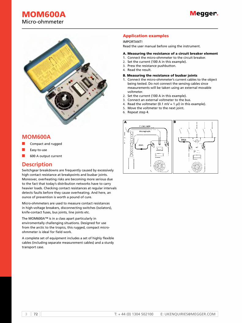
3 72 T: + 44 (0) 1304 502100 E: [email protected]
MOM600An compact and rugged
n Easy-to-use
n 600 A output current
DescriptionSwitchgear breakdowns are frequently caused by excessively high contact resistance at breakpoints and busbar joints. moreover, overheating risks are becoming more serious due to the fact that today’s distribution networks have to carry heavier loads. checking contact resistances at regular intervals detects faults before they cause overheating. And here, an ounce of prevention is worth a pound of cure.
micro-ohmmeters are used to measure contact resistances in high-voltage breakers, disconnecting switches (isolators), knife-contact fuses, bus joints, line joints etc.
The mom600A™ is in a class apart particularly in enviromentally challenging situations. Designed for use from the arctic to the tropics, this rugged, compact micro-ohmmeter is ideal for field work.
A complete set of equipment includes a set of highly flexible cables (including separate measurement cables) and a sturdy transport case.
Application examplesImPoRTANT! Read the user manual before using the instrument.
A. Measuring the resistance of a circuit breaker element1. connect the micro-ohmmeter to the circuit breaker.2. Set the current (100 A in this example).3. Press the resistance pushbutton.4. Read the result.
B. Measuring the resistance of busbar joints1. connect the micro-ohmmeter’s current cables to the object
being tested. Do not connect the sensing cables since measurements will be taken using an external movable voltmeter.
2. Set the current (100 A in this example).3. connect an external voltmeter to the bus.4. Read the voltmeter (0.1 mV = 1 µΩ in this example).5. move the voltmeter to the next joint.6. Repeat step 4.
A B
MOM600Amicro-ohmmeter

73 3WWW.mEggER.com
SpecificationsSpecifications are valid at nominal input voltage and an ambient temperature of +25 °C, (77 °F). Specifications are subject to change without notice.
EnvironmentApplication field The instrument is intended for use
in high-voltage substations and industrial environments
Temperature
Operating 0 °C to +50 °C (32 °F to +122 °F)
Storage & transport -40 °C to +70 °C (-40 °F to +158 °F)
Humidity 5% – 95% RH, non-condensing
CE-markingEMC 2004/108/eC
LVD 2006/95/eC
GeneralMains voltage 115 / 230 V AC, 50 / 60 Hz
Power consumption (max) 115 V, 4370 VA230 V, 7360 VA
Protection Miniature circuit breakers, thermal cut-outs
Dimensions
Instrument 356 x 203 x 241 mm (14” x 8” x 9,5”)
Transport case 610 x 290 x 360 mm (24.0” x 11.4” x 14.2”)
Weight, 115 V model 25 kg (55.1 lbs) 43.1 kg (95 lbs) with accessories and transport case
Weight, 230 V model 24.7 kg (54.5 lbs), 42.8 kg (94.4 lbs) with accessories and transport case
Current cables 2 x 5 m (16 ft), 50 mm²
Sensing cables 2 x 5 m (16 ft), 2.5 mm²
Measurement sectionResistance
Range 0 – 1999 μΩ
Resolution 1 μΩ
Inaccuracy ±1% of reading +1 digit (at 100 – 600 A test current)
Output, 115 V modelCurrent 0 – 600 A DC
Open circuit voltage 5.2 V DC
Current shunt output 10 mV / 100 A ±0.5%, max 60 mV out, max 10 V to protective earth (ground)
Output, 230 V modelCurrent 0 – 600 A DC
Open circuit voltage 9 V DC
Current shunt output 10 mV / 100 A ±0.5%, max 60 mV out, max 10 V to protective earth (ground)
Max. load capacity, 115 V modelCurrent adjustment set to 100%
Output cur-rent
Min. output voltage
Max. load time
Rest time
Input current
100 A DC 4.6 V - - 8 A
300 A DC 3.8 V 1.5 min. 15 min. 20 A
600 A DC 2.6 V 10 s 5 min. 38 A
Max. load capacity, 230 V modelCurrent adjustment set to 100%
Output cur-rent
Min. output voltage
Max. load time
Rest time
Input current
100 A DC 8.3 V – – 6 A
300 A DC 7.2 V 2.5 min. 15 min. 16 A
600 A DC 5.6 V 15 s 5 min. 32 A
MOM600Amicro-ohmmeter
ORDERING INFORMATIONProduct Order Code
mom600Acomplete with: cable set gA-05053 ground cable gA-00200 Transport case gD-00010115 V mains voltage
BB-11190
230 V mains voltage BB-12290
optional accessories
cable set 10 m2 x 10 m (33 ft), 35 mm2 (current cables)2 x 10 m (33 ft), 2.5 mm2 (sensing cables)Weight: 16.8 kg (37 lbs)
gA-07103
cable set 15 m2 x 15 m (49 ft), 35 mm2 (current cables)2 x 15 m (49 ft), 2.5 mm2 (sensing cables)Weight: 29.4 kg (65 lbs)
gA-09153
calibration shunt600 A/60 mV
BB-90020
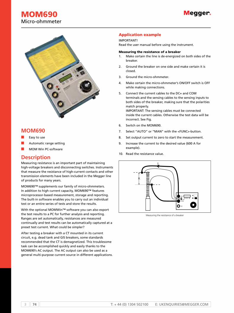
3 74 T: + 44 (0) 1304 502100 E: [email protected]
MOM690micro-ohmmeter
MOM690n Easy to use
n Automatic range setting
n mom Win Pc-software
Descriptionmeasuring resistance is an important part of maintaining high-voltage breakers and disconnecting switches. Instruments that measure the resistance of high-current contacts and other transmission elements have been included in the megger line of products for many years.
mom690™ supplements our family of micro-ohmmeters. In addition to high current capacity, mom690™ features microprocessor-based measurement, storage and reporting. The built-in software enables you to carry out an individual test or an entire series of tests and store the results.
With the optional momWin™ software you can also export the test results to a Pc for further analysis and reporting. Ranges are set automatically, resistances are measured continually and test results can be automatically captured at a preset test current. What could be simpler?
After testing a breaker with a cT mounted in its current circuit, e.g. dead tank and gIS breakers, some standards recommended that the cT is demagnetized. This troublesome task can be accomplished quickly and easily thanks to the mom690’s Ac output. The Ac output can also be used as a general multi-purpose current source in different applications.
Application exampleImPoRTANT! Read the user manual before using the instrument.
Measuring the resistance of a breaker1. make certain the line is de-energized on both sides of the
breaker.
2. ground the breaker on one side and make certain it is closed.
3. ground the micro-ohmmeter.
4. make certain the micro-ohmmeter’s oN/oFF switch is oFF while making connections.
5. connect the current cables to the Dc+ and com terminals and the sensing cables to the sensing inputs to both sides of the breaker, making sure that the polarities match properly. ImPoRTANT: The sensing cables must be connected inside the current cables. otherwise the test data will be incorrect. See Fig.
6. Switch on the mom690.
7. Select “AUTo” or “mAN” with the <FUNc>-button.
8. Set output current to zero to start the measurement.
9. Increase the current to the desired value (600 A for example).
10. Read the resistance value.
Measuring the resistance of a breaker

75 3WWW.mEggER.com
MOM690micro-ohmmeter
Max. load resistance / current, 230 V modelCable set Standard Standard +
Ext. 1Standard + Ext. 1
2 x 15 m 95 mm²
At 300 A 18 mΩ 14 mΩ 11 mΩ 18 mΩ
At 600 A 3.0 mΩ 1.8 mΩ
Max. current
750 A 570 A 480 A 690 A
Output DC (CAT I), 115 V modelCurrent (A) Voltage (V) Max. load time Input current
(A)0 7.3 – 0.8
50 6.9 30 min.
100 6.4 10 min. 10
200 5.5 90 s 19
300 4.8 50 s
400 3.9 30 s 38
500 3.0 15 s
5751) 2.5 10 s
600 2.2 8 s 52
700 1.5 5 s
8002) 0.9 –1) Maximum current with standard cables 2 x 5 m 50 mm²2) At 800 A and above, instant shut off
note: The above figures shows maximum load time from cold state 25 °C. They are notvalid for repeated tests
Output AC (CAT I), 115 V modelCurrent (A) Voltage (V) Max. load time Rest time0 8.7 Cont. –
660 3.5 2 s 4 min.note: The DC and AC outputs must not be loaded at the same time.
Output DC (CAT I), 230 V modelCurrent (A) Voltage (V ) Max. load time Input current
(A)0 9.4 – 0.4
50 9.0 30 min.
100 8.6 10 min. 6
200 8.0 90 s
300 7.2 50 s
400 6.4 40 s
500 5.7 30 s
600 5.0 15 s 33
700 4.3 8 s
7501) 3.8 5 s
8002) 3.6 – 421) Maximum current with standard cables 2 x 5 m 50 mm²2) At 800 A and above, instant shut off
note: The above figures shows maximum load time from cold state 25 °C. They are notvalid for repeated tests
Output AC (CAT I), 230 V modelCurrent (A)
Voltage (V AC)
Max. load time Rest time
0 11.2 Cont. –
660 4.5 2 s 4 min.note: The DC and AC outputs must not be loaded at the same time.
SpecificationsSpecifications are valid at nominal input voltage and an ambient temperature of +25 °C, (77 °F). Specifications are subject to change without notice.
EnvironmentApplication field The instrument is intended for use in
high-voltage substations and industrial environments.
Temperature
Operating 0 °C to +50 °C (32 °F to +122 °F)
Storage & transport -40 °C to +70 °C (-40 °F to +158 °F)
Humidity 5% – 95% RH, non-condensing
CE-markingEMC 2004/108/eC
LVD 2006/95/eC
GeneralMains voltage 115 / 230 V AC, 50 / 60 Hz
Power consumption (max)
115 V, 5980 VA (at 600 A output) 230 V, 9660 VA
Protection Miniature circuit breaker, thermal fuse, software
Dimensions
Instrument 350 x 270 x 220 mm (13.8” x 10.6” x 8.7”)
Transport case 610 x 290 x 360 mm (24.0” x 11.4” x 14.2”)
Weight, 115 V model 24 kg (52.9 lbs) 38.9 kg (85.7 lbs) with accessories and transport case
Weight, 230 V model 23.7 kg (52.2 lbs) 38.6 kg (85.1 lbs) with accessories and transport case
Available languages english, French, German, Spanish, Swedish
Current cables 2 x 5 m (16 ft), 50 mm²
Sensing cables 2 x 5 m (16 ft), 2.5 mm²
Optional current cable sets
Ext.1 extension 2 x 5 m, 50 mm²
Ext.2 extension 2 x 10 m, 50 mm²
2 x 15 m (49.2 ft) 95 mm²
Measurement sectionAmmeterRange 0 – 800 A
Resolution 1 A
Inaccuracy 100 – 800 A, ±1% of reading +1 digit 50 – 99 A, ±(2% of reading +2 digits) 0 – 49 A, not specified
ResistanceRange 0 – 200 mΩ, >200 mΩ not specified
Resolution 1 μΩ
Inaccuracy 100 – 800 A, ±1% of reading +1 digit 50 – 99 A, ±2% of reading +2 digits 0 – 49 A, not specified
Max. load resistance / current, 115 V modelCable set Stan-
dardStandard + Ext. 1
Standard + Ext. 1
2 x 15 m 95 mm²
At 300 A 10 mΩ 6 mΩ 3 mΩ 10 mΩ
Max. current
575 A 420 A 360 A 540 A

3 76 T: + 44 (0) 1304 502100 E: [email protected]
Optional accessories
PC Software MOMWinAn optional Windows® program named momWin is available for mom690. It can be used to control measurement, analyse the results and report the results from a Pc. It also enables you to retrieve test results stored previously in mom690.
All readings are saved in AScII-format and can be easily exported to your favourite spreadsheet program. Results can be presented in table or diagram form in momWin.
The program runs in Windows® 95, 98, NT, 2000 or XP. minimum requirement is a 486 computer with 8 mB of RAm.
Incl. serial cable for RS-232 port.
Cable set and current shunt
MOM690micro-ohmmeter
ORDERING INFORMATIONProduct Order Code
mom690complete with: cable set standard gA-05055 ground cable gA-00200 Transport case gD-00182115 V mains voltage
BB-41190
230 V mains voltage BB-42390
optional
Pc Software momWinIncl. serial cable for RS-232 port
BB-8010X
cable set 15 m (49 ft)2 x 15 m (49 ft), 95 mm2 (current cables) 2 x 15 m (49 ft), 2.5 mm2 (sensing cables) Weight: 29.4 kg (64.8 lbs)
gA-09155
cable extension setsSince all current cables have bayonet connectors, standard cables can be easily prolonged with 5- or 10-metre extension sets if so desired. In situations requiring high currents and long cable lengths, heavier cable sets may be necessary however.
Extension cable set No. 1 2 x 5 m (16 ft), 50 mm2 (current cables). 2 x 10 m (33 ft), 2.5 mm2 (sensing cables). Weight: 7.5 kg (16.5 lbs)
gA-05057
Extension cable set No. 22 x 10 m (33 ft), 50 mm2 (current cables). 2 x 15 m (49 ft), 2.5 mm2 (sensing cables). Weight: 15 kg (33 lbs)
gA-05107
calibration shuntAn optional calibration shunt (600 A/60 mV) can be ordered for mom690, that enables you to make certain that the instrument readings remain correct.
BB-90024
Transport case XLWith space for the standard 5 m cable set + extension cable set No. 1 or No. 2.
gD-00042
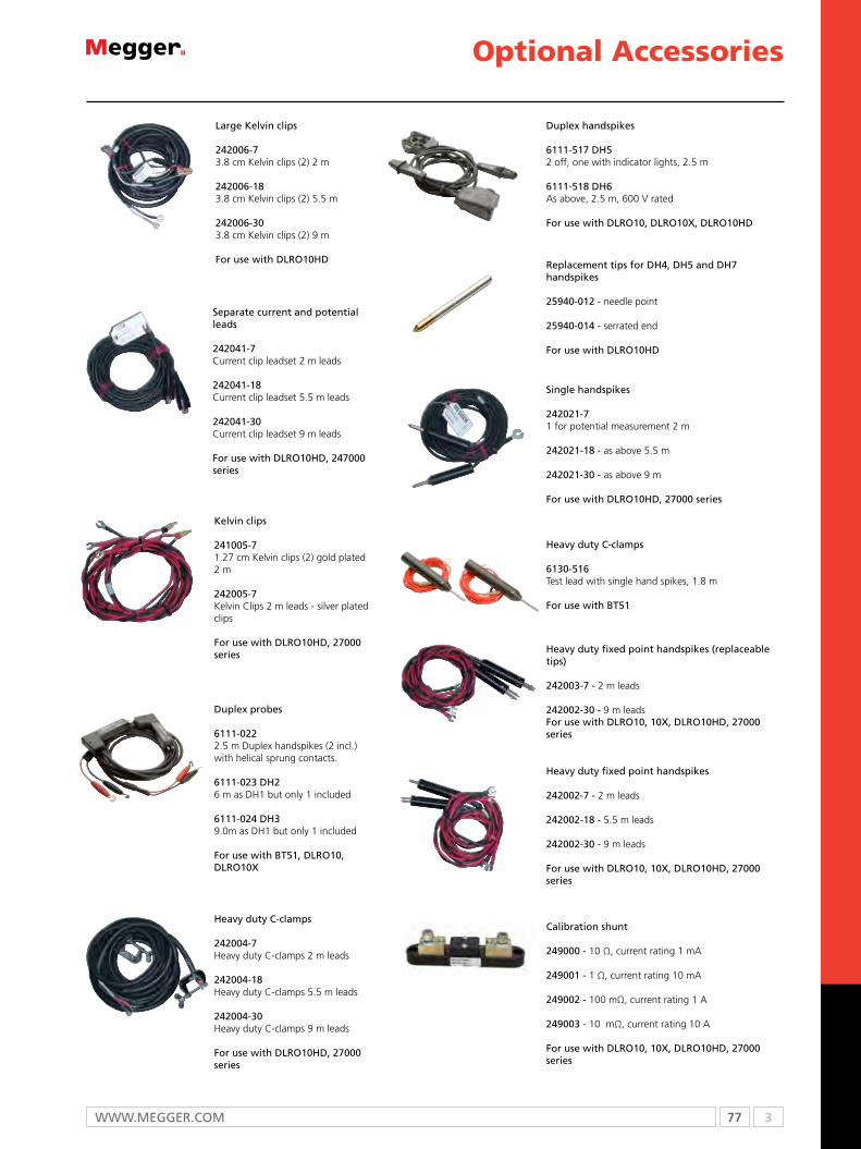
77 3WWW.mEggER.com
Optional Accessories
Separate current and potential leads
242041-7 Current clip leadset 2 m leads
242041-18 Current clip leadset 5.5 m leads 242041-30 Current clip leadset 9 m leads
For use with DLRo10HD, 247000 series
Large Kelvin clips
242006-73.8 cm Kelvin clips (2) 2 m
242006-183.8 cm Kelvin clips (2) 5.5 m
242006-303.8 cm Kelvin clips (2) 9 m
For use with DLRo10HD
Single handspikes
242021-71 for potential measurement 2 m
242021-18 - as above 5.5 m
242021-30 - as above 9 m
For use with DLRo10HD, 27000 series
Kelvin clips
241005-71.27 cm Kelvin clips (2) gold plated 2 m
242005-7 Kelvin Clips 2 m leads - silver plated clips
For use with DLRo10HD, 27000 series
Heavy duty c-clamps
242004-7 Heavy duty C-clamps 2 m leads
242004-18 Heavy duty C-clamps 5.5 m leads
242004-30 Heavy duty C-clamps 9 m leads
For use with DLRo10HD, 27000 series
Replacement tips for DH4, DH5 and DH7 handspikes
25940-012 - needle point
25940-014 - serrated end
For use with DLRo10HD
calibration shunt
249000 - 10 Ω, current rating 1 mA
249001 - 1 Ω, current rating 10 mA
249002 - 100 mΩ, current rating 1 A
249003 - 10 mΩ, current rating 10 A
For use with DLRo10, 10X, DLRo10HD, 27000 series
Heavy duty fixed point handspikes
242002-7 - 2 m leads
242002-18 - 5.5 m leads
242002-30 - 9 m leads
For use with DLRo10, 10X, DLRo10HD, 27000 series
Heavy duty fixed point handspikes (replaceable tips)
242003-7 - 2 m leads
242002-30 - 9 m leads For use with DLRo10, 10X, DLRo10HD, 27000 series
Duplex handspikes
6111-517 DH5 2 off, one with indicator lights, 2.5 m
6111-518 DH6 As above, 2.5 m, 600 V rated
For use with DLRo10, DLRo10X, DLRo10HD
Heavy duty c-clamps
6130-516Test lead with single hand spikes, 1.8 m
For use with BT51
Duplex probes
6111-022 2.5 m Duplex handspikes (2 incl.) with helical sprung contacts.
6111-023 DH2 6 m as DH1 but only 1 included
6111-024 DH3 9.0m as DH1 but only 1 included
For use with BT51, DLRo10, DLRo10X

3 78 T: + 44 (0) 1304 502100 E: [email protected]
Optional Accessories
gA-90000Kelvin probes with cables
For use with mom2
Xc-06000Bluetooth kit - headset and dongle for PC
For use with mom2
gA-00386Kelvin clamps with cables
For use with mom2
gA-02053Cable set
gA-00200Ground cable
BD-90022Shunt
For use with mJÖLNER600
BD-90002Calibration kit
For use with mom2
gD-00620Soft carry case for MOM202,charger and cables
For use with mom202
6430-193 Accesssory pouch, leather
For use with BT51
Shunt calibration certificate
cERT-NISTCertificate of calibration for shunts, nIST
For use with DLRo10, DLRo10X, DLRo10HD
BD-90010Remote control
For use with mJÖLNER600

79 3WWW.mEggER.com
Optional Accessories

4 80 T: +44 (0) 1304 502100 E: [email protected]
Selection guide ........................................................................................... 81Technical information .................................................................................. 82PA9Plus portable power analyzer ................................................................ 84PA9 Wireless portable quality analyzer ........................................................ 85MDP series distribution profiliers ................................................................. 88MR-4 meter adapter recorders .................................................................... 90SLM-8 8 channel recording volt-ammeter .................................................... 92Specifications and ordering information for SLM-8 ...................................... 94
Harmonic pollution and voltage transients on supplies are by no means uncommon, and can have expensive consequences. The key to diagnosing and eliminating these ills is effective supply monitoring.
Power Quality
4

81 4WWW.mEggEr.com
SELECTION GUIDE
n feature £ option PA9 Plus PA9 Wireless
MDP MR4 SLM8
Portable power quality analyzer n n
Distribution profilers n
Meter socket recorder n
Recording volt ammeter n
Records voltage n n n n
Records current n n n n n
Records Sag and Swells n n n n
Record transients n n n
Records power n n n
Records energy n n n
Records power factor n n £ n
Harmonic trending n n £
Harmonic direction n n
Waveform capture n n £ n
On site data analysis n n
Intelligent download n n
Wireless modem n n
Powered off Phase A n n n n
Indoor and outdoor operation (IP54) n n n n n

4 82 T: +44 (0) 1304 502100 E: [email protected]
What is power quality?For today’s electrical engineers, power quality is an important issue.
Voltage sags, swells, transients as well as harmonic pollution are
by no means uncommon, and can have expensive consequences.
The key to diagnosing and eliminating these ills is effective supply
monitoring.
In our modern world, devices which present a non-linear load to
the electrical supply system are everywhere. Almost every computer
or television, for example, has a switch-mode power supply, while
inverter-based variable speed drives are found in huge numbers
in virtually every office building and factory. Even the humble
fluorescent light fitting is likely to have an electronic ballast, which is
yet another non-linear load.
There’s no doubt that these devices perform valuable functions, and
that, in many cases, they are very energy efficient, but they do have
one significant drawback: by definition, non-linear loads present
to the supply system an impedance which varies rapidly with time.
Typically, for example, they may draw current only for a small part of
each cycle of the supply waveform.
The practical consequence of this behaviour is that non-linear
loads give rise to harmonic currents at multiples of the powerline
frequency. The presence of these harmonics in the supply can
adversely affect the operation of electronic equipment, such as
computers and telecommunication installations, but their effect is
by no means limited to these relatively sensitive low-power devices.
Harmonic currents can cause excessive and even dangerous heating
in power distribution transformers and neutral supply conductors,
and can also cause nuisance tripping in circuit breakers.
Clearly, for safe and dependable operation of electrical installations,
and the equipment connected to them, harmonics must be brought
under control. There can, however, be no true control without
effective measuring and monitoring, so let’s have a look at what’s
needed to measure and monitor supply harmonics.
First, let’s consider the locations where we are likely to be measuring
harmonics. Among the most usual places are adjacent to electrical
distribution equipment, or near loads which are suspected either of
generating harmonics or of being affected by them. In other words,
measurements need to be taken in a variety of on-site conditions.
This dictates that the instrument should be portable, robust and
insensitive to changes in ambient conditions.
Now, let’s consider the provision of power for the instrument.
Frequently, the only readily available power source is the one
which is under investigation. An instrument which requires a
clean, regulated supply for correct operation may, therefore, be
inconvenient or even impossible to use. A far better option is a
portable power quality meter which is self-powered from the supply
under test.
The requirements for portability and stability make the use of
digital measurement techniques virtually essential. While it would
be possible to envisage an analogue instrument based on tuned
filters and amplifiers, it would be a brave soul who would guarantee
stability and accuracy outside of a laboratory environment!
Power quality monitoring often needs to be continued over a
considerable period of time, and if several circuits have to be
monitored, it is much easier and more economical to do this with
one multi-channel instrument than with several single-channel
devices. Further, multi-channel operation means that all records are
absolutely synchronised, allowing easy and accurate comparison of
the results on different channels.
In many applications, it is also desirable to have facilities for event-
triggered recording, where the instrument can be set to record
the data associated with a particular power quality phenomenon.
This might, for example, be a voltage swell. The best equipped
instruments will record events while continuing to store waveform
data, and to log trends in voltages, currents and power flows.
A large-capacity memory is needed to store the data collected,
together with non-volatile external memory facilities which allow it
to be transferred easily to a PC, and software to permit subsequent
detailed analysis. It’s also worth mentioning that the ability to review
and edit the data rapidly prior to transfer is also useful, since it
avoids the time wasted in transferring and processing information
which is not of interest.
All of the factors we have discussed so far, give a good idea of the
capabilities of the ideal modern power quality monitor. In summary,
it should be portable, self-powered from an unregulated AC/DC
source, measure harmonics up to at least the 60th, offer a real-
time graphical display, indicate the direction of harmonic power
flow, accommodate multiple channels, and have large data storage
facilities.
These are the very factors which were used by Megger engineers as
the basis for the design of the PA-9 Plus portable power analyser.
Designed specifically for use on site, without a computer, this
compact instrument records power quality and power flow, as well
as evaluating trends for harmonics, total harmonic distortion (THD),
and total demand distortion (TDD).
Power quality matters. Reliable operation of electrical equipment
can only be assured if engineers pro-actively manage the quality of
the power delivered to their electrical installations, and the only way
that they achieve this is by regular and systematic monitoring.

83 4WWW.mEggEr.com
Detailed chartsMegger PA9 plus and PA9 wireless allow you to graph and overlay
any or all recorded parameters on a single chart. This feature
dramatically reduces the time for problem analysis and identification.
An important feature allows you to zoom in/zoom out of particular
windows, as well as to copy and paste data directly from the chart
to a third-party spreadsheet, database, or analysis program. The
scan-line feature provides exacting data and timing information at
any particular point in the chart, thus removing all guesswork and
approximation in the investigation. In addition, you can graphically
view vector information and relationships for any demand interval,
as well as modify the look of the chart axis and title information. All
charts and graphs may be printed directly to your local or network
printer, and copied and pasted to third-party applications.
New advanced Metreport utility For more sophisticated reporting requirements, our optional
METREPORT software creates tailored reports and customized
reporting templates. This utility directly reads power quality data
files, producing sophisticated reports incorporating company specific
logos, in-depth charts, and applicable text into a Microsoft® Word
compatible document.
The downloaded data files from either PA9Plus or PA9 Wireless can
be automatically analyzed against standard specifications such as
EN50160, CBEMA, SEMI-F47, SARFI or IEEE519 just to name a few.
You can also create your own custom templates to perform data
analysis using the Wizard built into the software. Just answers the
questions when prompted.
MetReport software offers the unprecedented feature of data
analysis and custom reporting at your fingertips.
Demand data chart
Cycle waveform with bar chart
Selective data download and preview capabilities
Comparison to industry tolerance curves using optional METREPORT software
Flicker trending per IEC61000-4-15 and EN50160

4 84 T: +44 (0) 1304 502100 E: [email protected]
PA9Plusn Designed to comply with all applicable IEC, IEEE, CSA and
EN Standards
n Trends harmonics, THD & TDD and provides real-time
graphical display of individual harmonic power
n Provides harmonic direction
n Can record both AC and DC volts/current
n Can be powered off of AUX or Phase A
n NEMA 4 weather proof enclosure
DescriptionThe PA9Plus is the latest innovation of the successful PA-9 Power Quality Analyzer platform. It incorporates newly enhanced key features including a faster Digital Signal Processor (DSP) to support continually evolving capabilities, a full 12 MB of nonvolatile internal memory and standard auxiliary power input capabilities.
The PA9Plus is CE marked, supports several international languages, and adheres to applicable European and North American standards (EN50160, IEC61000-4-15, IEEE1159, IEEE519), including automatic phase lock loop synchronization of input frequencies ranging from 20 Hz to 70 Hz, flicker measurements and recording, and out of limits/frequency trending.
The optional removable memory capabilities allows internally recorded data to be copied directly to an external standard compact flash card using the same technology available with most of today’s digital cameras. This means that without a computer on site, data can be manually or automatically copied from the instrument to external memory cards, increasing the effective instrument memory storage to the size of the card used. Similarly, new configuration setups may be programmed in the same, simple manner.
Specifications are at 25 ° C (77 ° F)
Voltage (4 differential input channels)
Voltage rangeAuto ranging between 20-300; 300-600 V ac/V dc scales, true RMS through 63rd harmonic
Voltage accuracy±0.25% of reading ±0.05% of range through 63rd harmonic
Crest factor
Voltage3.5 limited to 1500 V peak (does not include impulse)
current 1.4 of full scale at peak input
Current (5 channels)
current resolution 0.1% of full scale
current accuracy
±0.25% of reading ±0.05% of range through 63rd harmonic, plus the current probe accuracyCurrent channels receive 0 to 1 Volt RMS from probes
Frequency
Fundamental frequency 50 Hz or 60 Hz
Frequency responsedc to the 63rd harmonic with low pass anti-aliasing filter
Frequency resolution 0.01 Hz
Frequency accuracy 0.01 Hz at 60 Hz
Phase angle error
±1° referenced to first voltage channel at 60 Hz
Power supply
Primary input 90-600 V ac, 50/60 Hz, 100-600 V dc. Powered fromchannel 1 or auxiliary IEC computer-style power input
Battery (12 V backup battery included)
Battery recharge time 16 hours
run through time15 minutes, below 90 V ac/110 V dc cutoff. If recording, resume recording on power restoration
Data retention10 years with nonvolatile, solid-state flash memory
Environmental
operating temperature -20 ° to +50 ° C (-4 ° to 122 ° F)ambient temperature
HumidityMeets NEMA 4X, rain resistant; 90% non-condensing, not watertight
caseNEMA 4X, (IP54), nonconductive, corrosion resistant, rain resistant, not submersible
Communications
rs2323 wire up to 115200 baud rate, DB9 standard
modem (optional) Internal modem
External rs232 (optional)cFor serial port access to instrumentdata while front lid remains closed
Mechanical data
DimensionsPortable - 330 x 254 x 152 mm (13 x 10 x 6 in.)
Weight 5.6 kg (15 lbs)
SPECIFICATIONS
PA9PlusPortable power analyzer

85 4WWW.mEggEr.com
PA9 WirelessPortable quality analyzer
PA9 Wirelessn Trends voltage, current, imbalance, power, energy,
events, flicker (PST/PLT), THD, TDD, individual harmonics,
and frequency
n Real-time, graphical display of harmonic content, power
and source direction
n Wireless modem allows for remote analysis of data,
remote data retrieval capabilities and remote unit
configuration
n Intelligent download—preview and retrieve only the
information of interest
n Remote communications and alarming capabilities. Poll
the unit automatically or have it email you in case of an
event
DescriptionThe PA9 Wireless is the latest innovation of the successful PA9 Power Quality Analyzer platform. It incorporates enhanced key features including a wireless modem for remote communication, a full 12 MB of nonvolatile internal memory and standard auxiliary power input capabilities as well as an optional external flash card for added memory.
The PA9 Wireless is CE marked, supports several international languages, and adheres to applicable European and North American standards (EN50160, IEC61000-4-15, IEEE1159, IEEE519), including automatic phase lock loop synchronization of input frequencies ranging from 20 Hz to 70 Hz, flicker measurements and recording, and out of limits/frequency trending.
The wireless modem allows the user to configure the unit remotely, view real-time data via the remote screen, as well as preview all recorded data without downloading the data. The user can then choose what data they wish to download.
Disclaimer - The PA9 Wireless unit should be used for data analysis ONLY and NOT for real time monitoring and/or control applications.
Specifications are at 25 ° C (77 ° F)
Voltage (4 differential input channels)
Voltage rangeThree high voltage channels
Autoranging between 20 to 600 V ac/dc scales and low voltage channel autoranging between 0.1 to 350 V ac or V dc, true RMS through the 63rd harmonic
Voltage accuracy±0.25% of reading ±0.05% of range through 63rd harmonic
Crest factor
Voltage
Limited to 1500 V peak (not including impulses) for high voltage channels Limited to 500 V peak for low voltage channel
current 1.4 of full scale at peak input
Current (5 channels)
current resolution 0.1% of full scale
current accuracy
±0.25% of reading ±0.5% of range, plus the current probe accuracyCurrent channels receive 0 - to 1 V RMS from probesCurrent channel voltage 0.25% of reading, ±5 mV
Frequency
Fundamental frequency20 Hz to 70 Hz auto-ranging via phase lock loop
Frequency responsedc to the 63rd harmonic with low pass anti-aliasing filter
Frequency resolution 0.01 Hz
Frequency accuracy 0.01 Hz at 60 Hz
Phase angle error
±1° referenced to first voltage channel at 60 Hz
Power supply
Primary Input 90-600 V ac, 50/60 Hz, 100-600 V dc. Powered fromchannel 1 or auxiliary IEC computer-style power input
Battery (12 V backup battery included)
Battery recharge time 16 hours
run through timeIf recording, 15 minutes when instrument power input falls below min. voltage level
Data retention10 years with nonvolatile, solid-state flash memory
Environmental
operating temperature -20 °C to +50 °C (-4 °F to 122 °F)ambient temperature
HumidityMeets NEMA 4X, rain resistant; 90% non-condensing, not watertight
caseNEMA 4X, (IP54), nonconductive, corrosion resistant, rain resistant, not submersible
Communications
rs2323 wire up to 115200 baud rate, DB9 standard
Wireless raven modem GPS
Mechanical data
DimensionsPortable - 330 x 254 x 152 mm (13 x 10 x 6 in.)
Weight 5.6 kg (15 lbs)
SPECIFICATIONS
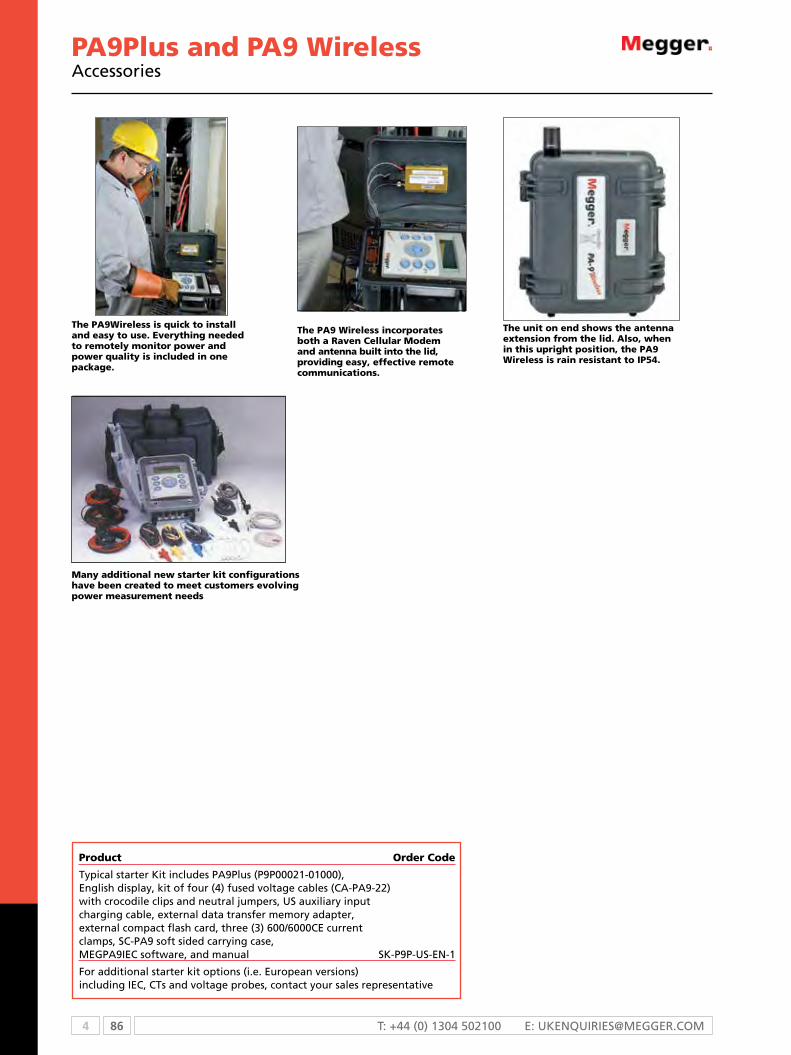
4 86 T: +44 (0) 1304 502100 E: [email protected]
Many additional new starter kit configurations have been created to meet customers evolving power measurement needs
Product Order Code
Typical starter Kit includes PA9Plus (P9P00021-01000), English display, kit of four (4) fused voltage cables (CA-PA9-22) with crocodile clips and neutral jumpers, US auxiliary input charging cable, external data transfer memory adapter, external compact flash card, three (3) 600/6000CE current clamps, SC-PA9 soft sided carrying case, MEGPA9IEC software, and manual SK-P9P-US-EN-1
For additional starter kit options (i.e. European versions) including IEC, CTs and voltage probes, contact your sales representative
The PA9Wireless is quick to install and easy to use. Everything needed to remotely monitor power and power quality is included in one package.
The PA9 Wireless incorporates both a Raven Cellular Modem and antenna built into the lid, providing easy, effective remote communications.
The unit on end shows the antenna extension from the lid. Also, when in this upright position, the PA9 Wireless is rain resistant to IP54.
PA9Plus and PA9 WirelessAccessories
87 4WWW.mEggEr.com
Recording Option F/W
0 = None 1 = Not Yet Available
Future F/W Option
0 = None 1 = Not Yet Available
Advanced F/W Options
0 = None 1 = Not Yet Available
Firmware Options F/W
0 = None 1 = Customized Text Option
Communications Capabilities
0 = Modem Ready
Voltage Input Color Coding
0 = Standard 1= Australian
Power Cable
1 = USA 2 = UK 3 = European
F/W Language
1 = English 2 = French 3 = Spanish
Removable Flash Module
0 = None
2 = Flash card with USB reader
4 = Flash card with parallel reader
Future Option F/W
0 = None 1 = Not Yet Available
Order a PA9Plus or a PA9 Wireless configured to your specific application. To determine the catalog number, fill in the blanks below with the corresponding number from the detailed information boxes.
Ordering example: To order a PA9Plus with the removable memory option, flash card with USB reader, English display, and US auxiliary power cord, request catalog number P9P 0 0 0 2 1 — 0 1 0 0 0
Fill in these blanks with the corresponding letter or number.
P9P 0 0 0 2 1 — 0 1 0 0 0
ORDERING INFORMATION
Future Firmware Option
0 = None 1 = Not Yet Available
Future Firmware Option
0 = None 1 = Not Yet Available
Future Firmware Option
0 = None 1 = Not Yet Available
Customer-defined Firmware Text
0 = None 1 = Customized Text Option
Communications Capabilities
0 = None 1 = Modem
Voltage Input Color Coding
0 = Standard 1= Australian
Power Cable
1 = USA 2 = UK 3 = European
Firmware Language
1 = English 2 = French 3 = Spanish
Removable Memory Option
0 = None
2 = Flash card with USB reader
4 = Flash card with parallel reader
External RS-232 Port
0 = Not Installed 1 = Installed
Note: Megger recommends using the Raven Wireless Modem. Megger does not guarantee unit compatibility with other brands.
Ordering example: To order a PA9 Wireless with the Raven Modem and the removable memory option, flash card with USB reader, English display, and US auxiliary power cord, request catalog number P9W 0 1 0 2 1 — 0 1 0 0 0
Fill in these blanks with the corresponding letter or number.
P9W 0 1 0 2 1 — 0 1 0 0 0

4 88 T: +44 (0) 1304 502100 E: [email protected]
MDP SeriesDistribution profiler
MDP seriesn choice of three models that record currents up to 1000
amps, with an additional 200 amp over-range
n Power and power factor
n Waveform capture and harmonic analysis up to the 32nd
order
n THD and Harmonics for both current and voltage
n Lightweight, durable unit housed in a weatherproof
urethane case
n Sturdy battery compartment with easy plug-in access for
quick data retrieval
DescriptionThe mDP series of distribution profilers provides power
utilities with the most accurate and extensive information
ever to precisely evaluate loading on feeders/overhead lines
and to identify needed upgrades or replacement. Three
different models range from a simple “current-only” version
to the most advanced unit that offers a number of user-
requested features. Each mDP can be easily upgraded to the
next model at any time.
mDP1 (basic)
n records actual current rms magnitude up to 1000
amps, with an additional 200 amp over-range
mDP2 (mid range)
records:
n Actual current rms magnitude up to 1000 amps, with an
additional 200 amp over-range
n Power factor and power
mDP3 (advanced)records:
n Actual current rms magnitude up to 1000 amps, with an
additional 200 amp over-range
n current and relative voltage waveforms
n Power factor and power
n Harmonics
n THD (Total Harmonic Distortion)
system planners, distribution engineers and troubleshooters
can easily access, review and record (via a date and time
stamp) the following:
n Peak load value/time growth studies
n Phase/load imbalance surveys
n Time/day fluctuation analysis
n capacitor bank placement analysis
All specifications at 25 ºC unless otherwise specified
conductor size.6 cm to 2.5 cm (0.25 in. to 1.2 in.) cable outside diameter
current range 10 to 1000 A : 1% ±2 A
conductor voltage 4 kV to 35 kV
Data retention 10 years with no power
real time clock accuracy 0.005% over one year
Enviromental
operating temperature -40 ºC to +60 ºC (-40 ºF to +140 ºF)
storage temperature -50 ºC to +85 ºC (-58 ºF to 185 ºF)
operating humidity 0 to 90% noncondensing
storage humidity 0 to 95% noncondensing
Safety
IEC 61010
EmF IEC 61326:2002
ingress protection IP54
Power supply
Battery
4 commercial “AA” batteries. For extended temperature applications (below 0º and above +40 ºC) Lithium high range “AA” batteries are recommended
Mechanical data
Dimensions25.4 x 12 x 5 cm (10 H x 5 L x 2 W in.)
Weight 2.1 kg (4.6 lbs)
SPECIFICATIONS

89 4WWW.mEggEr.com
MDP SeriesDistribution profiler
ORDERING INFORMATIONProduct Order Code
single channel 1000 Amp distribution profiler cE approved; isolated, single channel recording profiler for distribution line primary up to 35 kV ac. Hot-stick mountable. unit records time stamped values of current magnitude with 1 amp resolution for days, weeks or months depending upon data storage interval. True rms through the 50th harmonic.
mDP1
single channel 1000 Amp distribution profilercE marked; in addition to the same featuresas the mDP1, this unit also records power andpower factor
mDP2
single channel 1000 Amp distribution profilercE marked; in addition to the same featuresas the mDP2, this unit also records current andrelative voltage waveforms, THD data as wellas harmonic data through the 32nd harmonic
mDP3
note: An rs-232 computer interface cable or usB cable and Ac adapter are required for individual units.
included accessories
Battery holder 36164
rs-232/com port cable cA-rs232
nylon carrying case for up tothree Profilers and accessories
36133
Phase iD label kit; includes 2 sets of 3 labels,Alpha A, B & c / numeric 1, 2 & 3
35863
usB 2.0 A-B cable cA-usB
Product Order Code
“AA” battery (4 required) 23415
metrosoft software for Windows 32-bit applications software for iBm and compatible computers. Programs unit, provides data retrieval, generates graphs, reports and data files, compatible with microsoft® Excel software, and saves recorder setup files. compatible with Windows nT, Win2000 and XP
36175-1
instruction manual AVTMMDP
starter kits
consists of 3 mDP1 Profilers, (1) Ac adapter,(1) nylon carrying case, Phase iD label kit,(1) rs-232/com port cable, (1) usB 2.0 A-B cable,(12) “AA” batteries, metrosoft software,(1) instruction manual
sk-mDP1
same as sk-mDP1 except includes3 mDP2 Profilers instead of mDP1 Profilers
sk-mDP2
same as sk-mDP1 except includes 3mDP3 Profilers instead of mDP1 Profilers
sk-mDP3
The Profilers are quickly installed at any point on thedistribution line and are mountable to many readilyavailable clamp sticks.
Easy plug-in access allows for quick data retrieval viaRS-232 and USB cable ports. The battery compartment isspecifically designed for simple removal and installation.
4 90 T: +44 (0) 1304 502100 E: [email protected]
MR-4meter adapter recorders
MR-4n records voltage and current at the meter
n ideal for split-phase residential and light commercial
investigations
n Detects sags, swells, flicker, loose neutrals and harmonics
n installs quickly and safely
DescriptionWith more and more equipment and appliances emerging
with sensitive electronics, power quality problems have found
their way into homes and offices. The mr-4 meter Adapter
recorders provide a powerful tool to track down these
problems. They are ideal for split-phase residential and light
commercial power quality monitoring.
The mr-4 simultaneously records the two line currents in
addition to the two line voltages, as well as computes the line
to line voltage and neutral current. They are digital recorders
totally contained in a standard universal ring or ringless type
meter adapter.
The mr-4 records voltage and current at the meter. it is
installed quickly and safely. There are no external boxes or
connections, and no customer panel boxes left open.
Input channels
L1-n, L2-n (L1-L2 computed)2 voltage, 2 current L1 & L2 (neutral current computed)
Range
Voltage50-150 V RMS line to neutral; 250 V peak line to neutral
current 5-200 A RMS/Phase; 350 A peak
Peak175 A max. continuous without damage
Sample rate
256 samples/cycle per channel (DSP Based)Statistics stored: min/max and interval RMS for voltage and current per storage interval. Detects sub-cycle events down to 65 microseconds. Also records power, energy, harmonics and flicker event detection
Accuracy and resolution
Voltage accuracy ±0.35% of reading
Voltage resolution 0.1 V AC
current accuracy (mr-4 only) ±0.35% of reading
real time clock 0.01%
Software
Metrosoft® 32-bit software for Windows
graphs Voltage/current/demand, THD etc.
reportsTabular, event (swell, sag, flicker) regulation table and histogram
Power
Battery backup Sealed lead acid battery
run-through time2 minute below 160 V cutoff. Resume recording on power restoration
Data retention14 days with fully charged battery. Battery charges from L1-L2 voltage
min. charging voltage 180 V AC
Display
4 digit, 7 segment LED display inside meter adapter. Display continuously scrolls through VL1, VL2, countdown time
Recording
Manual (slide switch inside meter adapter), scheduled run, voltage present, current present, auto-stop, delayed start
Environmental
operating temperature -30 ºC to +65 ºC (-22 ºF to +149 ºF)
ingress protectionWeathertight when meter is reinstalled and sealed
SPECIFICATIONSSPECIFICATIONS

91 4WWW.mEggEr.com
MR-4meter adapter recorders
SPECIFICATIONSORDERING INFORMATIONProduct Order Code
Four channel recorder (2 voltage/2 current) for split phase service (120/240 V). DSP and flash PROM based. This recorder is totally self-contained within a universal ring/ringless meter adapter for forms 2S, 12S, 25S. Samples at 256 samples/cycle, has integral internal display and external indicating LEDs to indicate recording status, suspected loose neutral, flicker event and surge/sag event. Also, calculates L1-L2 voltage and neutral current. Captures 65 microsecond voltage and current events. Isolated RS-232 port facilitates viewing real time data and retrieving data without removing recorder. Standard 128 KB memory stores 33,000 readings. Includes software for Windows 95/98/NT/2000, neutral blade, neutral clip lead and manual
mr-4
options and accessories
metrosoft software for Windows 32-bit Windows applications software for iBm and compatible computers. Programs unit, provides data retrieval, generates graphs, reports and data files, compatible with:
Lotus 1-2-3 and Excel software, and saves recorder setup files. compatible with Windows nT and Windows 95, 98, me, Win2000
35173-1
memory module - 1 mB memory upgrade mm-mr-1
computer interface cable - rs232 isolated (only 1 per computer required)
cA-mr
Power quality option - captures waveforms based on time/event trigger. requires mm-mr-1
mm-Pq
Power flow option - records Watts, Vars, VA, power factor and other key power parameters.Available for mr-4 only
mm-PF
External power supply- charges mr-4 from 120 V Ps-mr
nylon carrying case, soft-sided CC-MR
charger cable with plug for car cigarette lighter Dc-mr
Product Order Code
Fuse kit EF-mr
neutral blade nJ-mr
neutral clip lead nL-mr
starter kits
includes mr-4 meter adapter recorder, mm-mr-1 memory expansion and cc-mr nylon carrying case
sk-mr-4-01
same as sk-mr-4-01 plus Dc-mr charger cable for car cigarette lighter and Ps-mr external power supply
sk-mr-4-02
same as sk-mr-4-02 plus cA-mr optically isolated rs232 cable
sk-mr-4-03
same as sk-mr-4-03 plus mm-Pq power quality option and mm-PF power flow option
sk-mr-4-04
Product kits
includes (6) mr-4 meter adapter recorders, (6) mm-mr-1 memory expansion modules, (6) Dc-mr charger cables, (3) Ps-mr external power supplies, (1) cA-mr- rs232 computer interface cable and (6) cc-mr nylon carrying case
Pk-mr4-6
includes (12) mr-4 meter adapter recorders, (12) mm-mr-1 memory expansion modules, (12) Dc-mr charger cables, (6) Ps-mr external power supplies, (1) cA-mr rs232 computer interface cable and (6) cc-mr nylon carrying case
Pk-mr4-12

4 92 T: +44 (0) 1304 502100 E: [email protected]
SLM-88 channel recording volt-ammeter
SLM-8n 3-phase voltage, current and flicker recorder
n Records for days, weeks or months
n Removable PCMCIA memory card option
n Creates detailed charts and reports
n Rugged and weatherproof design
DescriptionThe SLM-8 is a low cost, 8-channel paperless recording
volt-ammeter used for measuring and recording the
true RMS values of up to four voltage channels and four
current channels. It is the ideal investigative tool for utility
troubleshooters, service investigation groups, meter shop
technicians, and facility managers to identify and document
the presence of three-phase and single-phase voltage
complaints utilizing associated load current information to
locate the source of the problem.
True RMS, minimum RMS, maximum RMS, and flicker
information may be recorded. High-speed sampling indicates
events as fast as one cycle the 4 line x 20 character display is
backlit for easy viewing and an LED indicates when the unit
is recording. The unit comes complete with a comprehensive
graph/reporting package.
The loose neutral indication feature of the SLM-8 is for use
on 3-wire split phase systems utilizing V1 and V2 in the
calculations for loose neutral diagnosis. If a loose neutral
problem is determined, a front-panel LED labeled “Loose
Neutral” lights up and remains lit until cleared. Using ms-slW
Metrosoft, the loose neutral analysis criteria can be changed
as required.
number of channels 4 voltage, 4 current
Frequency 50 or 60 Hz
sample rate (per channel) 4 sample per cycle
Recording response time
Rising inputs: to 20% of final value in one cycle (16.7 msec); to rated accuracy in three cycles (50 msec) max.Failing inputs: to 63% of final value in one cycle (16.7 msec); to rated accuracy in six cycles (100 msec) max.
Voltage input ranges15 - 150 V, 30 - 300 V and 60 - 600 V, 720 V max without damage
current input ranges10, 100, 1000, 3000, 6000 A clamps, 600 V rated
resolution0.1 V on voltage channels; 0.1 A on current channels
maximum crest factor 3.5 to 1 (limited to 1500 V peak)
Memory
120 KB (60,000 readings); expandable to 1 MB internal memory (512,000 readings) or up to 2 MB (1,000,000 readings) with removable memory card option
real clock time 0.01% accuracy
storage intervalProgrammable from 6 cycle to 2 hours
Voltage accuracy
True RMS ±1.0% F.S. through 50th harmonic150 V FS unit: ±0.3% of reading ±0.1 V full scale300 V FS unit: ±0.3% of reading ±0.2 V full scale600 V FS unit: ±0.3% of reading ±0.4 V full scale
current accuracy ±0.3% of reading ±0.1 of full scale
Display
4 line x 20 character backlit LCD. Three separate LEDs on face panel indicate recording, out-of-limit and loose neutral occurrences
Battery
TypeInternal lead acid, 6 V, 0.5 Ah, one hour minimum ride-through recording time on backup battery
Data retention 130 days after low battery condition
charging time 5 hours at 100 V ac input
Minimum voltage for charging and self-powering
90 V ac on channel V1
Environmental
operating temperature -30 ºC to +50 ºC (-22 ºF to +122 ºF)
caseNEMA 4X nonconductive corrosion resistant weatherproof case
Mechanical data
Dimensions29.2 x 31.1 x 13.3 cm (11.5 x 12.3 x 5.3 in.)
Weight 7.3 kg (16 lbs)
SPECIFICATIONS

93 4WWW.mEggEr.com
SLM-88 channel recording volt-ammeter
Product Order Code Options and accessories
Starter Kits Includes SLM-8, mm-sl-500 KB memory expansion to 500 KBytes, CA-232-01 RS-232 cable, (3) cp-1000WCE current clamps with (3) CA-PA9-7 CT adapter cables and SC-PA9 soft-sided carry case. Includes software for Windows 95/98/NT/2000 SK-SLM-8-01
Includes SLM-8, mm-sl-500 KB memory expansion to 500 KBytes, CA-232-01 RS-232 cable, (3) cp-1000WCE current clamps, (3) cp-20CE current clamps, (6) CA-PA9-7 CT adapter cables and SC-PA9 soft-sided carry case. Includes software for Windows 95/98/NT/2000 SK-SLM-8-02
Integral PCMCIA card adapter for Type 1/SRAM cards.
Maximum internal memory allowed with this option is base 120 KB MA-SL Memory options
PCMCIA card; 1 MB (512,000 readings) MCI-1MB
PCMCIA card; 2 MB (1,000,000 readings) MCI-2MB
500 KB (225,000 readings) MM-SL-500KB
1 MB (500,000 readings) MM-SL-1MB
RS-232 computer interface cable CA-232-01
Current input extender cable, 15 ft CA-RA15E
Charging cable CA-RVA4
Fuse kit EF-SL
Hardware restart shorting plug HR-371
Soft-side nylon storage case SC-PA9
Metrosoft for Windows software: 32-bit application software for IBM and compatible computers. Programs recorder; provides data retrieval; generates charts, reports and data files; compatible with spreadsheet software; saves recorder setup files. Compatible with windows 95/98/NTV4.0+/2000/ME. Includes manual. 35173-1
ORDERINg INFORMATION
Future Option
0 = Not yet available 1 = Not yet available
SLM-8- X X X X X X X
Order a SLM-8 configured to your specific application. To determine the catalog number, fill in the blanks below with the corresponding number from the detailed information boxes.
SLM-8- 0 0 0 0 0 0 2
Ordering Example:
To order SLM-8 base unit with cover, 60 Hz frequency, and 1 MB internal memory, request catalog number: SLM-8-0000-002.
Memory
0 = 120 KB memory (60,000 readings)
1 = 500 KB memory (225,000 readings)
2 = 1 MB memory (500,000 readings)
Frequency
0 = 60 Hz only 1 = 50 Hz only
Cover
0 = Standard
Future Option
0 = Not yet available 1 = Not yet available
Future Option
0 = Not yet available 1 = Not yet available
Fill in these blanks with the corresponding number or letter.
PCMCIA Card Adapter
0 = None 1 = Yes

4 94 T: +44 (0) 1304 502100 E: [email protected]
Cat. No. Current Measurement Frequency Max. working Accuracy Phase shift range range range voltage
CP-600DC 600 A 1 to 400 A ac dc to 10 kHz 600 V rms 1.5% of rdg 10 to 200 A: <2.5º (600 A peak) @ -3 dB ±1 A (1 to 100 A) 200 to 400 A: <2º 1 to 600 A dc 2% of rdg (100 to 400 A) 45 to 65 Hz 2.5% of rdg (400 to 600 A dc only) CP-600/6000CE 600/6000 A, 20 to 6000 A 40 Hz to 20 kHz 600 V rms 1% of rdg <0.7º @ 50 Hz switchable ±200 mA CP-600/6000RT 600/6000 A, 20 to 6000 A 40 Hz to 5 kHz 600 V rms 1% of rdg <0.7º @ 50 Hz switchable ±200 mA CP-6000B7 600/6000 A, 20 to 6000 A 40 Hz to 5 kHz 1000 V rms 1% of rdg <1º @ 50 to 60 Hz switchable ±200 mA CP-100/1000CE 100/1000 A, 10 to 1000 A 40 Hz to 20 kHz 600 V rms 1% of rdg 0.7º @ 50 to 60 Hz switchable ±200 mA CP-100/1000RT 100/1000 A, 10 to 1000 A 40 Hz to 5 kHz 1000 V rms 1% of rdg 0.7º @ 50 to 60 Hz switchable ±200 mA Accuracy @ .1 to 10 A 0.01 to 10 A < 3% of rdg ±0.1A, not specified, Accuracy @ 10 to 100 A 10 A <3º, 50 A <1.5º, CP-1000WCE 1000 A 10 to 1000 A 30 Hz to 5 kHz 600 V rms <0.75% of rdg ±0.25 A 200 A <0.75º, Accuracy @ 100 to 1200 A 1000 A <0.5º <0.5% of rdg ±0.5 A Accuracy @ 0.1 to 1 A 0.01 to 1 A <2% of rdg ±0.2 A, not specified, CP-100CE 100 A 1 to 100 A 40 Hz to 10 kHz 600 V rms Accuracy @ 10 to 80 A 1 to 20 A <3º, <1% of rdg ±0.2A, 20 to 100 A <2º Accuracy @ 80 to 150 A <1.5% of rdg ±0.2 A CP-300/3000CE 300/3000 A, 10 to 3000 A 40 Hz to 20 kHz 1000 V rms 1% of rdg ±200 mA <0.7º @ 50 to 60 Hz switchable CP-300/3000RT 300/3000 A, 10 to 3000 A 40 Hz to 5 kHz 1000 V rms 1% of rdg ±200 mA <0.7º @ 50 to 60 Hz switchable CP-20CE 20 A 0.1 to 20 A 40 Hz to 10 kHz 600 V rms Accuracy @ 0.1 to 1 A 0.1 to 1 A <5º, <2.5% of rdg, 1 to 20 A <3º Accuracy @ 1 to 20 A <1% of rdg CP-5CE 5 A 0.1 to 10 A 40 Hz to 3 kHz 600 V rms 1% of rdg ±5 mV 1 to 5 A 1º, 5 to 10 A 1.5º
Specifications and ordering information
Current campsCP-5CECP-20CECP-100CE
Rain tight current probeCP-600/6000RTCP-300/3000RTCP-100/1000RTCP-6000B7
Current probeCP-600/6000CECP-300/3000CECP-100/1000CE
Current clampCP1000WCE

95 4WWW.mEggEr.com
Cat. No. Output Crest factor Rain Battery Inside Adapter requirements signal (Mid-range) tight powered Style Length dia, max (No adapter needed with PA-9 or PA-9Plus)
CP-600DC 1 mV/A ac: 3.3 9 V alkaline Clamp 9 ft 2 in. CA-PA9-7 to use probes with dc: 2.5 (approx. 80 hrs) cable PA7, SLM-8, RVA4, RA recorders CP-600/6000CE 1 mV/A, 4.5 N/A Flexible 36 in. 12 in. CA-PA9FCP-7 to use up 0.1 mV/A coil to 4 probes with PA7, SLM-8, RVA4, RA recorders CP-600/6000RT 1 mV/A, 4.5 n N/A Flexible 36 in. 12 in. CA-PA9FCP-7 to use up 0.1 mV/A coil to 4 probes with PA7, SLM-8, RVA4, RA recorders CP-6000B7 1 mV/A, 10 n 9 V Flexible 36 in. 12 in. CA-PA9-7 to use probes with 0.1 mV/A (2000 hrs. min.) coil PA7, SLM-8, RVA4, RA recorders CP-100/1000CE 10 mV/A, 9 N/A Flexible 36 in. 12 in. CA-PA9FCP-7 to use up 1 mV/A coil to 4 probes with PA7, SLM-8, RVA4, RA recorders CP-100/1000RT 10 mV/A, 9 n N/A Flexible 36 in. 12 in. CA-PA9FCP-7 to use up 1 mV/A coil to 4 probes with PA7, SLM--8, RVA4, RA recorders CP-1000WCE 1 mV/A 9 N/A Clamp 9 ft 2 in. CA-PA9-7 to use probes with cable PA7, SLM-8, RVA4, RA recorders CP-100CE 10 mV/A 3 N/A Clamp 9 ft .78 in. CA-PA9-7 to use probes with cable SLM-8, RVA4, RA recorders CP-300/3000CE 10 mV/A, 3 N/A Flexible 36 in. 12 in. CA-PA9FCP-7 to use up 1 mV/A coil to 4 probes with PA7, SLM-8, RVA4, RA recorders CP-300/3000RT 10 mV/A, 3 n N/A Flexible 36 in. 12 in. CA-PA9FCP-7 to use up 1 mV/A coil to 4 probes with PA7, SLM-8, RVA4, RA recorders CP-20CE 50 mV/A 3 N/A Clamp 9 ft .78 in. CA-PA9-7 to use probes with cable PA7, SLM-8, RVA4, RA recorders CP-5CE 200 mV/A 3 N/A Clamp 9 ft 12 in. CA-PA9-7 to use probes with cable PA7, SLM-8, RVA4, RA recorders
Specifications and ordering information
Adapter C/N CA-PA9FCP-7, shown, is used with up to four probes with the PA7, SLM-8, RVA4 and RA recorders. Used with the following CTs: CP-600/6000CECP-300/3000CE CP-100/1000CE CP-600/6000RT CP-300/3000RTCP-100/1000RT
Adapter C/N CA-PA9-7, shown, is used with a probe with the PA7, SLM-8, RVA4 and RA recorders. Used with the following CTs:
CP-6000B7 CP-600DC CP-5CE CP-20CE CP-1000CE CP-1000WCE
Current clampCP-600DC

5 96 T: +44 (0) 1304 502100 E: [email protected]
Selection guide ........................................................................................... 97Technical information .................................................................................. 98Torkel820 battery load unit .................................................................... 101Torkel840/860 battery load unit ............................................................. 104BVM battery voltage monitor .................................................................... 108BGFT battery ground fault locator ............................................................. 110BITe2 and BITe2P battery impedance tester ............................................... 111BITe3 battery impedance tester ................................................................. 113PowerDB battery database management software .................................... 115BITe optional accessories ........................................................................... 116Torkel optional accessories ..................................................................... 118
Battery testing is crucial to ensure a battery system provides standby and emergency power to operate devices such as lighting, UPS systems, operating controls, switchgear components, protective relays and continuous process systems. Failure of a battery system within environments such as utilities, hospitals and manufacturing plants can result in operational failure of the devices connected to it.
With both capacity and impedance testers available, Megger can provide a battery tester tuned to your specific need.
Battery Test
5

97 5WWW.mEggER.comWWW.mEggER.com
SELECTION GUIDE
Torkel820
Torkel840
Torkel860
BVM BGFT BITe2 BITe2P BITe3
Capacity tester n n n
ohmic tester n n n
Battery ground fault tracer n
Tests cell impedance n n n
Cell voltage test n n n n
ripple current n n n
Float current test n
Intercell connection resistance test n n n
Spectrum analyzer n
online test n n n n n n n n
If you need...maximum value from your battery tester, you should use the right software: ProActive works with the BITE impedence testers, Torkel Win works with Torkel capacity testers, while PowerDB helps you to record and manage all your assets.

5 98 T: +44 (0) 1304 502100 E: [email protected]
Battery testing
Why Batteries are Needed
Batteries are used to ensure that critical electrical equipment is always on. There are so many places that batteries are used it is impossible to list them all. Some of the applications for batteries include:
nElectric generating stations and substations for protection and control of switches and relays
nTelephone systems to support phone service, especially emergency services
nIndustrial applications for protection and control
nBack up of computers, especially financial data and information
n“Less critical” business information systems
Without battery back-up hospitals would have to close their doors until power is restored. But even so, there are patients on life support systems that require absolute 100% electric power. For those patients, failure is not an option.
The many blackouts of recent years around the world show how critical electrical systems have become to sustain our basic needs. Batteries are used extensively and without them many of the services that we take for granted would fail and cause innumerable problems.
Why test battery systems
There are three main reasons to test battery systems:
nTo insure the supported equipment is adequately backed-up
nTo prevent unexpected failures
nTo forewarn/predict death
And, there are three basic questions that battery users ask:
nWhat is the battery capacity and state of health?
nWhen will it need to be replaced?
nWhat can be done to improve / not reduce its life?
Batteries are complex chemical mechanisms. They have numerous components including grids, electrolytes, posts, jar and cover, etc. — any one of which can fail. As with all manufacturing processes, no matter how well they are made, there is still some black art to batteries (and all chemical processes).
A battery essentially is two dissimilar metallic materials in an electrolyte. In fact, you can put two coins made from dissimilar metals in a citric fruit such as a lemon and have a battery. Obviously, an industrial battery is more sophisticated than a lemon battery. Nonetheless, a battery, to work the way it is supposed to work must be maintained properly. A good battery maintenance program may prevent, or at least, reduce the costs and damage to critical equipment due to an ac mains outage.
Even though there are many applications for batteries, they are installed for only two reasons:
nTo protect and support critical equipment during an ac outage
nTo protect revenue streams due to the loss of service
The following discussion about failure modes focuses on the mechanisms and types of failure and why impedance works so well at finding weak cells. Below is a section containing a more detailed discussion about testing methods and their pros and cons.
Why batteries fail
These are just some of the failure modes of lead acid batteries.
Positive grid corrosion is the normal designed in failure mode of lead acid batteries. The grids are lead alloys (lead-calcium, lead-antimony, lead-antimony-selenium) that convert to lead oxide over time. Since the lead oxide is a bigger crystal than lead metal alloy, the plate grows. Battery manufacturers design for extra space in the jars to account for this growth. At the “designed end-of-life”, the plates will have grown sufficiently to pop the tops off of the batteries. But excessive cycling, temperature and over- charging can also increase the speed of positive grid corrosion. Positive grid corrosion will cause a loss of capacity and a rise in battery impedance.
Plate sulfation is the process of converting active plate material to inactive white lead sulfate. Plate sulfation occurs naturally during the discharge cycle of the battery. The process reverses when the battery is recharged. However plate sulfation can become permanent if charger voltages are set too low. Low charge voltages, causing plate sulfation can occur due to voltage drops across the string caused by poor inter-cell (strap) connections. This is why it is imperative to tests the cell inter-connection as well as the cells themselves. Plate sulfation will cause a loss of capacity and a rise in battery impedance.
Dry-out is a phenomenon that occurs in VRLA batteries. Dry-out is due to excessive heat (lack of proper ventilation) or over charging which can cause elevated internal temperatures, high ambient (room) temperatures, etc. At elevated internal temperatures, the sealed cells will vent through the pressure release valve. When sufficient electrolyte is vented, the glass matte no longer is in contact with the plates, sulfating the plates immediately and increasing the internal impedance and reducing battery capacity.
Soft shorts (a.k.a. dendritic shorts) and Hard shorts occur for a number of reasons. Hard sorts are typically caused by paste lumps pushing through the matte and shorting out to the adjacent (opposite polarity) plate. Soft shorts, on the other hand, are caused by deep discharges. When the specific gravity of the acid gets too low, the lead will dissolve into it. Since the liquid (and the dissolved lead) are immobilized by the glass matte, when the battery is recharged, the lead comes out of solution forming dendrites inside the matte. In some cases, the lead dendrites short through the matte to the other plate. Internal battery shorts will cause a drop in voltage, a loss of capacity and can be seen as a drop in battery impedance.

99 5WWW.mEggER.com
Assault on batteries
In this electricity-dependent age, batteries are extremely important, not least as a source of power when mains supplies are unavailable. For example, in hospital, who would want to be in the middle of an operation when a power failure occurred and no back-up supply was available? It is no exaggeration to say that it would be hard for us to survive without battery back-up.
All batteries use chemical reactions to make electricity, and all comprise two dissimilar metallic materials in a current-carrying medium. In lead-acid batteries, the metallic materials are lead and lead oxide in a sulphuric acid medium. Nickel-cadmium (NiCd) batteries use nickel and cadmium compounds in a potassium hydroxide medium.
Nickel metal hydride (NiMH) batteries use the same nickel compound as NiCd cells, but the cadmium compound is replaced with a metallic hydride and the liquid electrolyte is replaced with a paste. NiMH and NiCd cells are virtually identical in performance; even their voltages are the same. For the purposes of stationary battery testing, however, this article focuses on lead-acid batteries.
How do we know if lead-acid batteries are good or bad? The traditional approach of testing only the voltage and specific gravity doesn’t work - never has and never will! The reasons are explained later in this article. Nevertheless, it is still possible to evaluate the performance and condition of a battery by well planned testing.
Battery tests
When performing battery maintenance no single test tells the whole story. The goal is to determine the present conditions and where the condition is headed. In order to determine this it is important to gather the proper data. A battery maintenance schedule should be developed in order to acquire the adequate amount of data to ensure safety and reliability
n Visual inspection
n Float voltage measurement
n Float current measurement
n Ripple current measurement
n Specific gravity measurement
n Temperature measurement
n Discharge testing
n Ohmic testing
n Strap resistance measurement
Float voltage
Low float voltages can indicate the battery charger is not set properly and the batteries are not fully charging. This can cause sulfation of the plates.
High float voltages can indicate the battery charger is not set properly and the batteries are over-charging. High float voltages can accelerate grid corrosion and create higher temperature inside the battery. The higher temperatures can lead to dry out in VRLA batteries and in some cases thermal runaway.
Specific gravity
A specific gravity measurement is a ratio of the density of a liquid with respect to density of water. In the case of batteries it is the electrolyte that is being measured. A specific gravity measurement
will provide the state of charge of the battery but will not provide any information regarding the capacity or state of health of the battery.
Float current
In order to keep a battery charged, there is a balance between the battery’s self-discharge and the action of the charger. The battery is always in a state of self-discharge which means that there is always a difference in EMF between the battery bank and the charger. This difference allows a small current (the float current) to flow to keep the battery fully charged.
Float current measurements can tell us if something is wrong but it will not tell us anything about state of charge (SOC), Capacity or state of health (SOH). However, even more important it will tell us if the batteries are in charge mode. A high float current would indicate the batteries are charging. If the batteries are charging you do not want to perform any further tests until they are fully charged and in float mode.
Current supplied by the charger passes through each cell, which causes the electrochemical process to reverse. The lead sulfate on the plates will convert back to sulfuric acid and active material. This will cause a change in the batteries capacity and internal impedance.
High float current can be an indicator of several things. It could indicate that the battery string is in charge mode. It could indicate there is a ground fault present in the system. High float current could also indicate a short in a battery or it could be a precursor to thermal runaway. In lead antimony batteries rising float current could indicate antimony poisoning of the cell.
Ripple current
Chargers convert AC from the mains supply into the DC needed to charge the battery. This conversion process is not perfect, however, and in all practical charges, residual AC appears at the charger output, this is the ripple current.
Ripple current generally increases slowly over time as the electronic components in the charger degrade. If, however, a rectifier diode fails in the charger, the ripple current can double instantly. An increase in ripple current above about 5 A RMS for every 100 Ah of battery capacity (5%) leads to increased temperature and shortened battery life.
Temperature
High temperatures do not spell immediate doom for batteries, but they can lead to premature failure, dry out as well as thermal runaway. For every increase of 10 °C, battery life is halved. This then means that a 20 year battery maintained at 30 °C instead of the specified 20 °C will only last about ten years. This can be a significant issue for VRLA batteries, since you cannot add water to them as they dry out.
Discharge current and time
Discharge current and time measurements are being used more frequently in on-line monitors as an aid to determining the amounts of energy removed from and fed into a battery. These measurements, at least in theory, allow the battery capacity to be calculated.
5 100 T: +44 (0) 1304 502100 E: [email protected]
Inter-cell connection resistance
Measurement of inter-cell connection resistance is an essential test, as it has been said that more than 50% of battery bank failures are due to loose inter-cell connectors. Inter-cell connections loosen due to the heating and cooling cycles caused by discharging and recharging. The cell terminal posts expand and contract and, as the lead from which they are made is very malleable. The poorer the connection the higher the impedance of the connection. This leads to larger voltage drops which can cause low charge voltages leading to battery plate sulfation.
Inter-cell resistance can be measured with either a low-resistance ohmmeter or a BITE battery tester.
Capacity
Capacity tests, also known as load tests, have long been seen as a necessary evil. Capacity testing with modern TORKEL discharge battery testers is much more efficient and effective than they once were, but they are still time-consuming. They may also have limited predictive value, depending upon how frequently they are performed.
Let us consider a battery bank that is designed to provide eight hours of back up time. A proper capacity test requires a second battery to take over the duty of the battery under test if a supply failure occurs while the test is in progress. A resistive load bank is also needed, which is connected to the battery bank under test, along with voltage leads for each battery in the bank. It is quite usual for this preparatory work to take around a day.
On the second day, everything is ready for the eight-hour discharge test. Frequently, however, this is preceded by measurement of the inter-cell connection resistance. There are two schools of thought about this. The first is that the resistances measured will not be true as-found values. The second is that the resistance test is a useful aid to ensuring that no major malfunctions occur which could have been avoided. The arguments are finely balanced, leaving the final decision to individual battery users.
With the battery fully discharged on the second day of testing, the third day is occupied by recharging, and the removal of the test leads. Even with this modestly sized battery, therefore, the test has taken three days, and has involved the use of an expensive loadbank and alternate battery. That having been said, it cannot be denied that a properly conducted capacity test is the only guaranteed way of accurately determining the capacity of a battery bank and some TORKEL battery testers will allow you to test the batteries while they are still in service.
Impedance
Impedance testing injects an AC signal into the battery cell and measure the current and voltage drop to determine the impedance of the cell.
As a battery ages it may corrode, sulfate, dry out or suffer a host of other effects based on maintenance, chemistry and usage. All of these effects cause a chemical change in the battery; which in turn causes a change in the battery’s internal impedance. Ohmic testing is not a direct measurement of capacity. However as a battery ages and loses active plate surface area due to corrosion, sulfation or dry-out, to name a few the battery’s capacity will drop. These conditions will also cause the impedance of the battery to rise.
Discharge testing is an absolute measurement of a batteries capacity and should be performed periodically every 2 to 5 years, depending on the batteries. Batteries can fail within that test period, especially VRLA batteries, which can fail within several months. This is why ohmic testing is important part of any battery maintenance program.
Data Analysis
Whatever testing regime is adopted, the result is sure to be a lot of data which, unless it is properly handled, it is likely to lead to analysis paralysis. The recommended approach is to use a database software to store and trend the data, rather than relying on traditional paper forms and laborious manual comparisons.
A specialised database that stores all measured parameters is almost as important as the tests themselves in determining the condition of batteries and banks. For example, limits can be set on measured and calculated parameters. If these limits are chosen to reflect the user’s required level of confidence in battery reliability, they can be a significant aid in getting the most from the battery and maximizing its service life.
Conclusion
Batteries have many failure modes, but with careful use and regular maintenance, the probability of in-service failures can be reduced dramatically. Proper testing and data analysis can help determine when a battery should be replaced, as well as reducing the need for unplanned battery replacements, thereby aiding budgetary planning and cutting overall costs.
Finally, a well-implemented battery maintenance program is a major step toward achieving the primary goal of every battery installation – that of providing dependable standby power whenever it is needed.
Ask for a copy of our Battery testing guide.
email [email protected]

101 5WWW.mEggER.com
Torkel820Battery load unit
TOrkEL820n Lightweight
n Expandable system
n Rugged and reliable for field use
n Test without disconnecting the battery from the
equipment it serves
DescriptionDuring a power outage, crucial telecommunication and radio
equipment must be kept operating by batteries. However, the
capacity of such batteries can drop significantly for a number
of reasons before their calculated life expectancy is reached.
Battery capacity should thus be checked to prevent expensive
downtime in the event of a power failure.
The most reliable way to determine battery capacity is to
conduct a discharge test. The ToRKEL820 features a unique
design that combines efficiency with portability. Using
ToRKEL820 you can discharge 24 and 48 V batteries at a
current of 270 A, and 12 V batteries at 135 A. moreover, two
or more ToRKEL820 units and/or extra load units, TXL, can
be linked together if you need higher current. Discharging
proceeds at constant current, constant power or constant
resistance, or in accordance with a pre-selected load profile.
The ToRKEL820 issues a warning and/or shuts down the test
automatically when a) the voltage has dropped to a certain
level, b) discharging has continued through a certain time
interval or c) a certain amount of capacity has been dissipated.
SPECIFICATIONS
Specifications Torkel820Specifications are valid at nominal input voltage and an ambient tem-perature of +25 °C, (77 °F). Specifications are subject to change without notice.
EnvironmentApplication field The instrument is intended for use in high-
voltage substations and industrial environ-ments.
Temperature
Operating 0 °C to +40 °C (32 °F to +104 °F)
Storage & transport
-40 °C to +70 °C (-40 °F to +158 °F)
Humidity 5% – 95% rH, non-condensing
CE markingLVD 2006/95/eC
EMC 2004/108/eC
GeneralMains voltage 100 – 240 V AC, 50 / 60 Hz
Power consumption 150 W (max)
Protection Thermal cut-outs, automatic overload protection
Dimensions
Instrument 210 x 353 x 700 mm (8.3” x 13.9” x 27.6”)
Transport case 265 x 460 x 750 mm (10.4” x 18.1” x 29.5”)
Weight 22.3 kg (49.2 lbs) 40.4 kg (89.1 lbs) with accessories and transport case
Display lCD
Available languages english, French, German, Spanish, Swedish
Measurement sectionCurrent measurementDisplay range 0.0 – 2999 A
Basic inaccuracy ±(0.5% of reading +0.2 A)
Resolution 0.1 A
Internal current measurementRange 0 – 270 A
Input for clamp-on ammeterRange 0 – 1 V
mV/A-ratio Software settable, 0.3 to 19.9 mV/A
Input impedance >1 MΩ
Voltage measurementDisplay range 0.0 – 60 VBasic inaccuracy ±(0.5% of reading +0.1 V)
Resolution 0.1 V
Time measurementBasic inaccuracy ±0.1% of reading ±1 digit
5 102 T: +44 (0) 1304 502100 E: [email protected]
Discharging capacity, examples12 V battery (6 cells) 2)
Final voltage Constant current Constant power
1.80 V / cell (10.8 V) 0 – 121 A 0 – 1.31 kW
1.75 V / cell (10.5 V) 0 – 117 A 0 – 1.23 kW
1.67 V / cell (10.0 V) 0 – 110 A 0 – 1.10 kW
24 V battery (12 cells) 2)
1.80 V / cell (21.6 V) 0 – 270 A 0 – 5.8 kW
1.75 V / cell (21.0 V) 0 – 266 A 0 – 5.59 kW
1.60 V / cell (19.2 V) 0 – 241 A 0 – 4.63 kW48 V battery (24 cells) 2)
1.80 V / cell (43.2 V) 0 – 270 A 0 – 11.6 kW
1.75 V / cell (42.0 V) 0 – 270 A 0 – 11.3 kW
1.60 V / cell (38.4 V) 0 – 259 A 0 – 9,9 kW2) 2.15 V per cell when test starts
Torkel820Battery load unit
Load sectionBattery voltage 10 – 60 V DC
Max. current 270 A
Max. power 15 kW
Load patterns Constant current, constant power, constant resistance, current or power profile
Current setting 0-270.0 A (2999.9 A) 1)
Power setting 0-15.00 kW (299.99 kW) 1)
Resistance setting 0.1-2999.8 Ω
Battery voltage range 2 ranges, selected automatically at start of test
Stabilization (For internal current measurement)
±(0.5% of reading + 0.5 A)
Battery voltage
Highest permissible current
resistor element (Nominal values)
range 1 10 – 27.6 V 270 A 0.069 Ω
range 2 10 – 55.2 V 270 A 0.138 Ω1) Maximum value for a system with more than one load unit
Inputs, maximal valuesEXTERNAL cURRENT mEASUREmENT EXTERNAL cURRENT
1 V DC, 300 V DC to ground. Current shunt should be connected to the negative side of the battery
START / SToP Closing / opening contact Closing and then opening the contact will start / stop Torkel. It is not possible to keep the contacts in closed position.
Delay until start 200 – 300 ms
Stop delay 100 – 200 ms
Battery 60 V DC, 500 V DC to ground
VoLTAgE SENSE 60 V DC, 500 V DC to ground
SERIAL 15 V
ALARm 250 V DC 0.28 A 28 V DC 8 A 250 V AC 8 A
Outputs, maximal valuesSTART / SToP 5 V, 6 mA
TXL relay contact
SERIAL <15 V
ALARm relay contact
103 5WWW.mEggER.com
SPECIFICATIONS
Torkel820Battery load unit
Specifications TXl830 / 850Specifications are valid at nominal input voltage and an ambient temperature of +25 °C, (77 °F). Specifications are subject to change without notice.
Environment
Application fieldThe instrument is intended for use in high-voltage substations and industrial environments.
Temperature
Operating 0 °C to +40 °C (32 °F to +104 °F)
Storage & transport -40 °C to +70 °C (-40 °F to +158 °F)
Humidity 5% – 95% rH, non-condensing
CE markingLVD 2006/95/eC
EMC 2004/108/eC
GeneralMains voltage 100 – 240 V AC, 50 / 60 Hz
Power consumption 75 W (max)
ProtectionThermal cut-outs, automatic overload protection
Dimensions
Instrument210 x 353 x 600 mm (8.3” x 13.9” x 23.6”)
Transport case265 x 460 x 750 mm (10.4” x 18.1” x 29.5”)
Weight13 kg (28.7 lbs) 21.4 kg (47.2 lbs) with transport case
Cable sets for TXL830 / 850
2 x 3 m (9.8 ft), 70 mm2, 270 A, with cable lug. Max. 100 V. 5 kg (11 lbs)
Load sectionTXL830 TXL850
Max. voltage (DC) 28 V 56 V
Max. current 300 A 300 A
Max. power 8.3 kW 16.4 kW
Internal resistance, 3-position selectorPosition 1 TXL830 TXL850
Current 0.275 Ω 0.55 Ω100 A at 27.6 V (12 x 2.3 V) at 55.2 V (24 x 2.3 V)78.5 A at 21.6 V (12 x 1.8 V) at 43.2 V (24 x 1.8 V)50.1 A – –39.2 A – –Position 2 TXL830 TXL850Current 0.138 Ω 0.275 Ω
200 A at 27.6 V at 55.2 V (24 x 2.3 V)156 A at 21.6 V 43.2 V (24 x 1.8 V)–Position 3 TXL830 TXL850
Current 0.092 Ω 0.184 Ω
300 A at 27.6 V at 55.2 V (24 x 2.3 V)235 A at 21.6 V 43.2 A (24 x 1.8 V)100 A – –78.4 A – –
OrDErING INFOrMATIONProduct Order Code
ToRKEL820complete with: cable set gA-00554 Transport case gD-00054
BS-49092
optional accessories
ToRKEL WinPc software
BS-8208X
Extra loadsTXL830
BS-59093
TXL850 BS-59095
cable setscable set for TXL830 and TXL8502 x 3 m, 70 mm2, with cable lug. max 100 V 270 A. Weight: 5.0 kg (11 lbs)
gA-00554
Sensing lead setcable set for measuring voltage at battery terminals. 2 x 5 m (16.4 ft)
gA-00210
clamp-on ammetersDc clamp-on ammeter, 200 ATo measure current in circuit outside ToRKEL
XA-12792
Dc clamp-on ammeter, 1000 ATo measure current in circuit outside ToRKEL
XA-12790

5 104 T: +44 (0) 1304 502100 E: [email protected]
Torkel840/860Battery load units
Torkel840/860n Batteries can be tested “in service”
n Unit adjusts to include load currents in the test
parameters
n User adjustable alarm and shutdown points to avoid
excessive discharge
n Easily expandable for larger battery banks using TXL
extra load units
n View test parameters/results “real time” as testing
progresses using ToRKEL WIN software
n Easily save results to a Pc for analysis, report generation
and storage
DescriptionBatteries in power plants and transformer substations must provide the equipment they serve with standby power in the event of a power failure. Unfortunately, however, the capacity of such batteries can drop significantly for a number of reasons before their calculated life expectancy is reached. This is why it is so important to check batteries at regular intervals, and the most reliable way of measuring battery capacity is to conduct a discharge test.
ToRKEL840 - UTILITY is used for battery systems ranging from 12 to 250 V – often encountered in switchgear and similar equipment. Discharging can take place at up to 110 A, and if higher current is needed, two or more ToRKEL840 units or extra load units, TXL, can be linked together. Tests can be conducted at constant current, constant power, constant resistance or in accordance with a pre-selected load profile.
ToRKEL860 - mULTI is designed primarily for people who travel from place to place to maintain battery systems having different voltages. It features excellent discharging capacity plus a broad voltage range and outstanding portability – a unique combination.
ToRKEL860 is used for systems ranging from 12 to 480 V, and discharging can proceed at up to 110 A. If higher current is desired, two or more ToRKEL860 units or extra load units, TXL, can be linked together. Discharging can take place at constant current, constant power, constant resistance or in accordance with a pre-selected load profile.
Application exampleTesting can be carried out without disconnecting the battery from the equipment it serves. Via a Dc clamp-on ammeter, ToRKEL measures total battery current while regulating it at a constant level.
The ToRKEL is connected to the battery, the current and the voltage alarm level are set. After starting the discharge ToRKEL keeps the current constant at the preset level. When the voltage drops to a level slightly above the final voltage, ToRKEL issues an alarm. If the voltage drops so low that there is a risk of deep discharging the battery, ToRKEL shuts down the test. The total voltage curve and the readings taken at the end of the test are stored in ToRKEL. Later, using the ToRKEL Win program, you can transfer these readings to your computer for storage, printout or export. If your Pc is connected to ToRKEL during the test, ToRKEL Win builds up a voltage curve on the screen in real time and displays the current, voltage and capacity readings. You can also control the test using ToRKEL Win.

105 5WWW.mEggER.com
SPECIFICATIONS
Torkel840/860Battery load units
Specifications Torkel840/860
Specifications are valid at nominal input voltage and an ambient temperature of +25 °C, (77 °F). Specifications are subject to change without notice.
EnvironmentApplication field The instrument is intended for use in
high-voltage substations and industrial environments.
Temperature
Operating 0 °C to +40 °C (32 °F to +104 °F)
Storage & transport -40 °C to +70 °C (-40 °F to +158 °F)
Humidity 5% – 95% rH, non-condensing
CE markingEMC 2004/108/eC
LVD 2006/95/eC
GeneralMains voltage 100 – 240 V AC, 50 / 60 Hz
Power consumption (max) 150 W
ProtectionThermal cut-outs, automatic overload protection
Dimensions
Instrument210 x 353 x 700 mm (8.3” x 13.9” x 27.6”)
Transport case265 x 460 x 750 mm (10.4” x 18.1” x 29.5”)
Weight21.5 kg (47.4 lbs) 38 kg (83.8 lbs) with accessories and transport case.
Display lCD
Available languagesenglish, French, German, Spanish, Swedish
Measurement sectionCurrent measurementDisplay range 0.0 – 2999 A
Basic inaccuracy ±(0.5% of reading +0.2 A)
Resolution 0.1 A
Internal current measurementRange 0 – 270 A
Input for clamp-on ammeterRange 0 – 1 V
mV/A-ratio Software settable, 0.3 to 19.9 mV/A
Input impedance >1 MΩ
Voltage measurementDisplay range 0.0 – 60 V
Basic inaccuracy ±(0.5% of reading +0.1 V)
Resolution 0.1 V
Display range 0.0 – 500 VBasic inaccuracy ±(0.5% of reading +1 V)
Resolution 0.1 V
Time measurementBasic inaccuracy ±0.1% of reading ±1 digit
Load section
Max. battery voltage288 V DC (Torkel840) 480 V DC (Torkel860)
Max. current 110 A
Max. power 15 kW
Load patternsConstant current, constant power, constant resistance, current or power profile
Current setting 0-110.0 A (2999.9 A) 1)
Power setting 0-15.00 kW (299.99 kW) 1)
Resistance setting 0.1-2999.8 Ω
Battery voltage range, TORKEL840
4 ranges, selected automatically at start of test
Battery voltage range, TORKEL860
5 ranges, selected automatically at start of test
Stabilization (For internal current measurement)
±(0.5% of reading +0.5 A)
Battery voltage
Highest permissible current
resistor element (Nominal values)
range 1 10 – 27.6 V 110 A 0.165 Ω
range 2 10 – 55.2 V 110 A 0.275 Ω
range 3 10 – 144 V 110 A 0.55 Ω
range 4 10 – 288 V 55 A 3.3 Ω
range 5 2) 10 – 480 V 55 A (max power 15 kW)
3.3 Ω
1) Maximum value for a system with more than one load unit2) Torkel860
Inputs, maximal valuesEXTERNAL cURRENT mEASUREmENT
1 V DC, 300 V DC to ground. Current shunt should be connected to the negative side of the battery
START / SToP Closing / opening contact Closing and then opening the contact will start / stop Torkel. It is not possible to keep the contacts in closed position.
Delay until start 200 – 300 ms
Stop delay 100 – 200 ms
Battery 480 V DC, 500 V DC to ground
VoLTAgE SENSE 480 V DC, 500 V DC to ground
SERIAL <15 V
ALARm 250 V DC 0.28 A 28 V DC 8 A 250 V AC 8 A
Outputs, maximal valuesSTART / SToP 5 V, 6 mA
TXL relay contact
SERIAL <15 V
ALARm relay contact
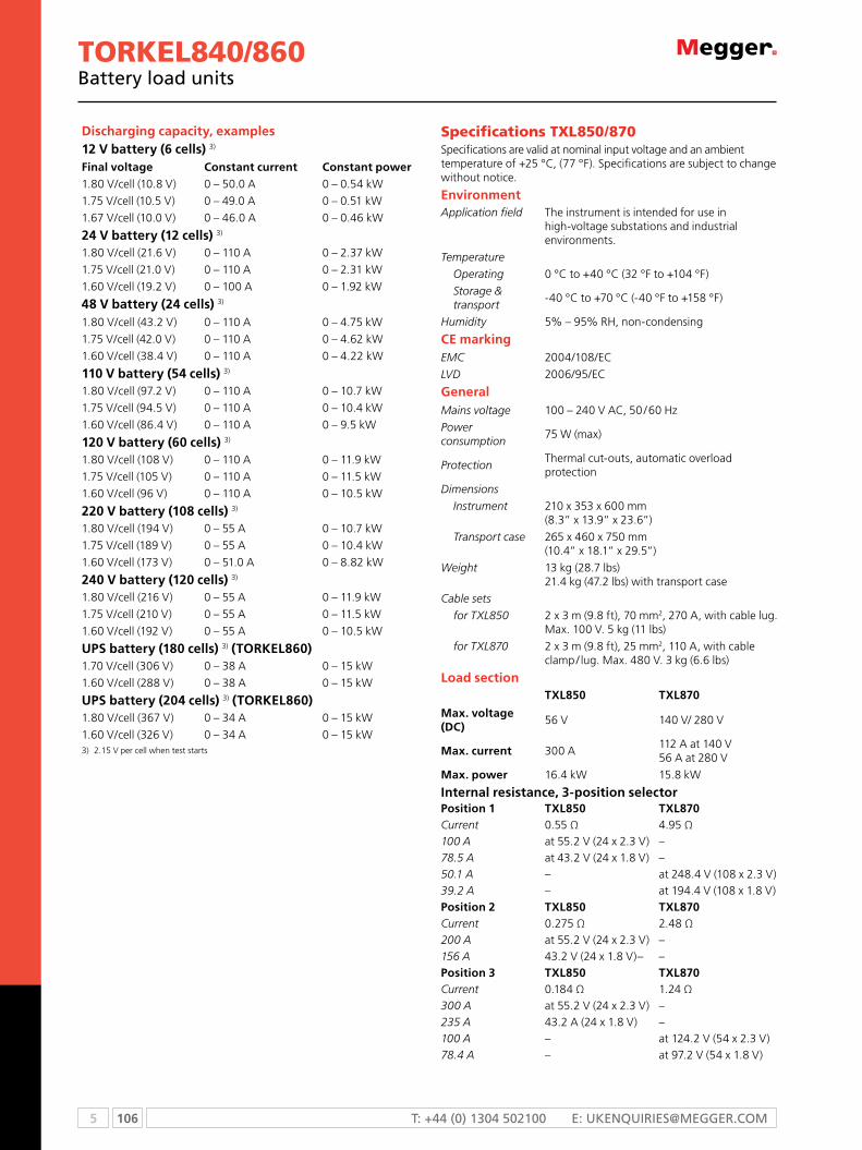
5 106 T: +44 (0) 1304 502100 E: [email protected]
Torkel840/860Battery load units
Specifications TXl 850 / 870Specifications are valid at nominal input voltage and an ambient temperature of +25 °C, (77 °F). Specifications are subject to change without notice.
EnvironmentApplication field The instrument is intended for use in
high-voltage substations and industrial environments.
Temperature
Operating 0 °C to +40 °C (32 °F to +104 °F)
Storage & transport
-40 °C to +70 °C (-40 °F to +158 °F)
Humidity 5% – 95% rH, non-condensing
CE markingEMC 2004/108/eC
LVD 2006/95/eC
GeneralMains voltage 100 – 240 V AC, 50 / 60 Hz
Power consumption
75 W (max)
ProtectionThermal cut-outs, automatic overload protection
Dimensions
Instrument 210 x 353 x 600 mm (8.3” x 13.9” x 23.6”)
Transport case 265 x 460 x 750 mm (10.4” x 18.1” x 29.5”)
Weight 13 kg (28.7 lbs) 21.4 kg (47.2 lbs) with transport case
Cable sets
for TXL850 2 x 3 m (9.8 ft), 70 mm2, 270 A, with cable lug. Max. 100 V. 5 kg (11 lbs)
for TXL870 2 x 3 m (9.8 ft), 25 mm2, 110 A, with cable clamp / lug. Max. 480 V. 3 kg (6.6 lbs)
Load sectionTXL850 TXL870
Max. voltage (DC)
56 V 140 V/ 280 V
Max. current 300 A112 A at 140 V 56 A at 280 V
Max. power 16.4 kW 15.8 kW
Internal resistance, 3-position selectorPosition 1 TXL850 TXL870Current 0.55 Ω 4.95 Ω100 A at 55.2 V (24 x 2.3 V) –78.5 A at 43.2 V (24 x 1.8 V) –50.1 A – at 248.4 V (108 x 2.3 V)39.2 A – at 194.4 V (108 x 1.8 V)Position 2 TXL850 TXL870Current 0.275 Ω 2.48 Ω200 A at 55.2 V (24 x 2.3 V) –156 A 43.2 V (24 x 1.8 V)– –Position 3 TXL850 TXL870Current 0.184 Ω 1.24 Ω300 A at 55.2 V (24 x 2.3 V) –235 A 43.2 A (24 x 1.8 V) –100 A – at 124.2 V (54 x 2.3 V)78.4 A – at 97.2 V (54 x 1.8 V)
Discharging capacity, examples12 V battery (6 cells) 3)
Final voltage Constant current Constant power1.80 V / cell (10.8 V) 0 – 50.0 A 0 – 0.54 kW
1.75 V / cell (10.5 V) 0 – 49.0 A 0 – 0.51 kW
1.67 V / cell (10.0 V) 0 – 46.0 A 0 – 0.46 kW
24 V battery (12 cells) 3)
1.80 V / cell (21.6 V) 0 – 110 A 0 – 2.37 kW
1.75 V / cell (21.0 V) 0 – 110 A 0 – 2.31 kW
1.60 V / cell (19.2 V) 0 – 100 A 0 – 1.92 kW
48 V battery (24 cells) 3)
1.80 V / cell (43.2 V) 0 – 110 A 0 – 4.75 kW
1.75 V / cell (42.0 V) 0 – 110 A 0 – 4.62 kW
1.60 V / cell (38.4 V) 0 – 110 A 0 – 4.22 kW
110 V battery (54 cells) 3)
1.80 V / cell (97.2 V) 0 – 110 A 0 – 10.7 kW
1.75 V / cell (94.5 V) 0 – 110 A 0 – 10.4 kW
1.60 V / cell (86.4 V) 0 – 110 A 0 – 9.5 kW
120 V battery (60 cells) 3)
1.80 V / cell (108 V) 0 – 110 A 0 – 11.9 kW
1.75 V / cell (105 V) 0 – 110 A 0 – 11.5 kW
1.60 V / cell (96 V) 0 – 110 A 0 – 10.5 kW
220 V battery (108 cells) 3)
1.80 V / cell (194 V) 0 – 55 A 0 – 10.7 kW
1.75 V / cell (189 V) 0 – 55 A 0 – 10.4 kW
1.60 V / cell (173 V) 0 – 51.0 A 0 – 8.82 kW
240 V battery (120 cells) 3)
1.80 V / cell (216 V) 0 – 55 A 0 – 11.9 kW
1.75 V / cell (210 V) 0 – 55 A 0 – 11.5 kW
1.60 V / cell (192 V) 0 – 55 A 0 – 10.5 kW
UPS battery (180 cells) 3) (TOrkEL860)1.70 V / cell (306 V) 0 – 38 A 0 – 15 kW
1.60 V / cell (288 V) 0 – 38 A 0 – 15 kW
UPS battery (204 cells) 3) (TOrkEL860)1.80 V / cell (367 V) 0 – 34 A 0 – 15 kW
1.60 V / cell (326 V) 0 – 34 A 0 – 15 kW3) 2.15 V per cell when test starts

107 5WWW.mEggER.com
Torkel840/860Battery load units
OrDErING INFOrMATIONProduct Order Code
ToRKEL840complete with: cable set gA-00550 Transport case gD-00054
BS-49094
ToRKEL860complete with: cable set gA-00550 Transport case gD-00054
BS-49096
optional accessories
ToRKEL WinPc software
BS-8208X
Extra loadsTXL850
BS-59095
TXL890 BS-59097
cable setscable set for TXL8502 x 3 m, 70 mm2, with cable lug. max 100 V 270 A. Weight: 5.0 kg (11 lbs)
gA-00554
Extension cable set, 110 A 2 x 3 m, 25 mm2. max 480 V Weight: 3.0 kg (6.6 lbs)
gA-00552
Sensing lead setcable set for measuring voltage at battery terminals. 2 x 5 m (16.4 ft)
gA-00210
clamp-on ammetersDc clamp-on ammeter, 200 ATo measure current in circuit outside ToRKEL
XA-12992
Dc clamp-on ammeter, 1000 ATo measure current in circuit outside ToRKEL
XA-12990
TORKEL Win
The TORKEL Win program runs on a PC under Windows®, you can transfer readings to your computer for storage, printout or export. If your PC is connected to a TORKEL820 during the test, TORKEL Win builds up a voltage curve on the screen in real time and displays the current, voltage and capacity readings. You can also control the test using TORKEL Win.

5 108 T: +44 (0) 1304 502100 E: [email protected]
BVMBattery voltage monitor
BVMn Automates battery voltage measurement
during capacity tests
n “Daisy-chain” design allows expandability
up to 120 units
n High accuracy and stability for precise data
collection
n Integrates with ToRKEL Win and PowerDB
Test data management software
n Wide voltage range
n Easy set-up
DescriptionThe megger BVm is a battery voltage measurement device that is used for the capacity testing of large, industrial battery banks commonly found in electrical power sub-stations, telecom facilities and computer data center UPS systems. When used in conjunction with a load device, such as the ToRKEL unit, and test data management software, such as PowerDB and ToRKEL Win, the BVm enables to perform a completely automated battery bank capacity test, according to IEc test method. The test also meet NERc/FERc requirements. The BVm is designed in modular form where one BVm device is used for each battery or “jar” in the string to be tested. one BVm for each battery connects to the next in a “daisy-chain” fashion, thereby providing easy and economical expandability to meet the testing requirements for small-to-large battery bank systems.
The included dolphin clip can be easily removed and exchanged with different styles of standard banana plug clamps and / or extension cables to accommodate any battery connection requirement.
Setup is fast and easy using the BVm. Each BVm is identical and can be connected in any battery test position, thus providing maximum flexibility and interchangeability of the BVms. Up to 120 BVms can be daisychained in a single battery bank under test.
The BVm “Auto Discovery” feature enables the host device to automatically determine the number of batteries under test and provide sequential identification of each BVm in the test string.
ApplicationEach BVm is identical and can be connected in any battery test position. Up to 120 BVms can be daisy-chained in a single battery bank under test.
A single cable connects the first BVm in the string to a power and signal connector. The laptop or other data acquisition device is connected via an Ethernet cable to the power and signal connector.

109 5WWW.mEggER.com
Specifications are valid at an ambient temperature of +25 ºc, (77 ºF). Specifications are subject to change without prior notice.
Environment
Application fieldThe instrument is intended for use in medium-voltage substations and industrial environments
Altitude <2000 m (6500 ft) above sea level
Temperature
operating 5 ºC to +50 ºC (41 ºF to +122 ºF)
Storage and transport 0 ºC to +60 ºC (32 ºF to +140 ºF)
Humidity 5% - 95% rH, non-condensing
CE marking
LVD 2006/95/eC
Emc 2004/108/eD
General
mains voltage 100/240 V AC, 50/60 Hz
Power consumption (max.) 50 VA
Protectionover voltage, reverse voltage, voltage transients, eSD
Mechanical data
Dimensions BVm unit75 x 64 x 25 mm(3 in. x 2.5 in. x 1 in.)
carrying case575 x 470 x 205 mm(22.6 in. x 18.5 in. x 8.1 in.)
Weight BVm unit 0.07 kg (0.15 lbs)
With accessories and carrying case 0.3 kg (0.66 lb)
Measurement section
maximum number of channels 120
Voltage ranges 0-5 V DC and 0-20 V DC
Resolution 1.00 mV both ranges
Inaccuracy <0.1% of full scale ±0.002 V DC
Battery string voltage 300 V DC (max.)
measurement input impedance 1 MΩ
SPECIFICATIONS
OrDErING INFOrMATION
Product Order Code
BVmIncluding: Dolphin clips, power and signal connector, power supply, connection cables and carrying case
BVm300 with ToRKEL Win softwareSystem of 31 BVm units cJ-59093
BVm600 with ToRKEL Win softwareSystem of 61 BVm units cJ-59093
Product Order Code
BVm300 with PowerDB softwareSystem of 31 units cJ-59193
BVm600 with PowerDB softwareSystem of 61 BVm units cJ-59196
BVmSingle unit
cJ-59090

5 110 T: +44 (0) 1304 502100 E: [email protected]
BGFTBattery ground fault tester
BGFTn Easily locates ground faults in ungrouded dc systems
n operates in high electrical noise environment
n Simplifies fault tracing by identifying fault
characteristic (resistive and capacitive) magnitudes
DescriptionThe battery ground fault tracer is an economical, easy-to-use
instrument that identifies, traces and locates ground faults in
ungrounded dc systems — on-line. It is particularly effective in
high electrical noise environments, as the strength of the test
signal can be adjusted.
The battery ground fault tracer accelerates fault location by
eliminating trial-and-error procedures and because faults can
be located without going off-line. It is particularly useful in
any industry where supply of power for operating measure-
ment, communication and control equipment is critical.
OrDErING INFOrMATION
Product Order Code
Battery ground fault tracer, 120/240 V ac, 50/60 Hz, cE marked
246100B
Included accessories
Fused source leads, 6 m (20 ft) (1 pair) 29386-3
current transformer, 5 cm (2 in.) with leads, 1.2 mm (4 ft) (1 pair)
29999-1
Ac power cord, 1.8 m (6 ft) (1) 17032
Feedback cable, 12 m (40 ft) (1) 29998
Padded accessory bag (1) 29996
Battery, 9 volt (1) 1482-1
Power source
Transmitter120/240 V ac, 50/60 Hz, 200 VA max.
Receiverone 9 V alkaline battery supplies up to 40 hours continuous
Source
Voltage Variable from 0 to 50 V rms
current load dependent from 0 to 1.7 A rms
Frequency 20 Hz, ±2%
Fault resistance
1 kΩ to 399 kΩ at 50 V; bridge accuracy ±10%
Line capacitance
0.01 to 11.1 µF; bridge accuracy ±20%
Display
TransmitterSeparate 3 digit lCD meters for voltsand current
Accuracy ±5%
ReceiverDigital meter display up to 1.999 (three gain selections)
Mechanical data
Dimensions (Transmitter)19 H x 47 W x 37 D cm (7.5 H x 18.5 W x 14.5 D in.)
Dimensions (Receiver)4 H x 9 W x 19 D cm(1.5 H x 3.5 W x 7.5 D in.)
Weight (Transmitter) 15.9 kg (35 lb)
Weight (Receiver) 0.3 kg (0.66 lb)
SPECIFICATIONS
Product Order Code
User manual AVTm 246100B
optional accessories
mini-cT, 12 mm (0.5 in.) with 1.3 m (4.25 ft) lead 30595

111 5WWW.mEggER.com
BITe®2 and BITe2PBattery impedance test equipment
Transmitter
Supply voltage100 to 130 V, 50/60 Hz, 200 VA max210 to 250 V, 50/60 Hz, 200 VA max
Source output current 10 A nominal, 50/60 Hz operation
Maximum battery string test voltage
275 V dc at source lead terminals (section the battery if >275 V dc)
Display
Digital LcD meter 0 to 15 A
Charger
Supply voltage100 to 130 V, 50/60 Hz, 14 VA210 to 250 V, 50/60 Hz, 14 VA
output6.50 V dc @ 1.10 A dc charging (max)9.60 V dc open circuit
receiver
Accuracyac impedance 5% +1 lSDdc voltage ±(0.5% of reading +1 lSD)
Precision Better than 0.5% one sigma
Voltage range and resolution
1 to 2.500 V dc, 1 mV resolution2.5 to 25.00 V dc, 10 mV resolution
Impedance range and resolution
0 to 1.000 mΩ, 1µΩ resolution1 to 10.00 mΩ, 10µΩ resolution10 to 100.0 mΩ, 0.1mΩ resolution
Setting time per reading
3 seconds maximum
Display
LCD, 2 x 16 characters
Supply
4.8 V dc, 1600 mAh, quick charge NiMH battery pack
Battery pack life, full charge 5 hours continuous
maximum cell/jar test voltage25 V dc between receiver and potential probe
CE Marking
lVD 2006/95/eC
eMC 2004/108/eC
Environmental
operating temperature 0 ºC to 40 ºC (32 ºF to 105 ºF)
Storage temperature -20 ºC to 55 ºC (-5 ºF to 130 ºF )
Humidity 20 to 90% rH, noncondensing
Mechanical data
BITE2 Transmitter16.5 H x 35.6 W x 27 D cm(6.5 H x 14 W x 10.6 D in.)
BITE2P Transmitter19 H x 47 W x 37 D cm(7.5 H x 18.5 W x 14.6 D in.)
Receiver (irregular shape)
BITE2P18 H x 29 W x 5 D cm(7.25 H x 11.25 W x 2 D in.)
Weight
BITE2 Transmitter 7.7 kg (17 lb)
BITE2P Transmitter8.2 kg (18 lb) alone, 14.5 kg (32 lb) packed
Receiver 0.7 kg (1.6 lb)
SPECIFICATIONS
BITE2 and BITE2Pn Determines condition of lead acid and Nicd cells up to
7000 Ah
n on-board Pass/Warning/Fail indications
n Robust, repeatable instruments
n on-line testing
n checks charger condition by measuring ac ripple
current
DescriptionThe BITE2 and BITE2P battery impedance test equipment
determine the condition of lead-acid and nickel-cadmium cells
up to 7000 Ah. An advanced feature set has been developed
that includes Pass/Warning/Fail calculations based on a user-
entered baseline value, advanced printing functions and
more. The case of the BITE2P consists of both the transmitter
and a carrying case for all of the standard accessories and
some of the optional accessories, in an all-in-one unit. The
BITE2 and its accessories fit into a sturdy canvas case with a
shoulder strap.
Bite 2P
Bite 2

5 112 T: +44 (0) 1304 502100 E: [email protected]
BITe®2 and BITe2PBattery impedance test equipment
OrDErING INFOrMATION
Product Order Code
BITE2, 110/230 V ac, 50/60 Hz, CE marked 246002B
BITE2P, 110/230 V ac, 50/60 Hz, CE marked 246004
Included accessories
Transmitter for BITE2 P30044-300
Transmitter for BITE2P P30044-100
Receiver P30620-3
Source leads, 6 m (20 ft), fused 29386-2
current sensor, 50 mm (2 in.) opening with 1.5 m (5 ft) lead
33863
cT extension cable, 6 m (20 ft) 33864-1
communication cable, 1.8 m (6 ft) 35340
charger cable 35341
Thermal paper 26999
PowerDB battery database management software
BI-9001
ac line cord, 2.5 m (8 ft) 17032-7
manual for BITE2 and BITE2P 246004
Accessory bag for BITE2 29996
Product Order Code
optional accessories
current sensor 12 mm (0.5 in.) opening with 0.8 m (2.5 ft) lead
246034
current sensor, RopecT™ 60 cm (24 in.) length 246050
current sensor, RopecT™ 90 cm (36 in.) length 246051
cT extension cable, 6 m (20 ft) 246033
current source leads, 3 m (10 ft), fused 246147
current source leads, 9.1 m (30 ft), fused 246347
current source leads, 12.2 m (40 ft), fused 246447
Bar code wand with preprinted code sheet 246201

113 5WWW.mEggER.com
BITE3n Determines health of lead-acid cells up to 2000 Ah
n on-line testing with Pass/Warning/Fail calculations
n measures impedance, interconnection resistance and cell
voltage
n Windows cE operating system with 32 mB of memory
n measures float and ripple currents
n Built in Spectrum Analyzer for troubleshooting.
DescriptionThe BITE3 battery impedance test equipment determines
the health of lead-acid cells up to 2000 Ah by taking measure-
ments of the most important battery parameters. The BITE3
measures cell impedance, an internal ohmic test, cell voltage,
intercell connection resistance and ripple current. And, for the
first time in a battery instrument, the BITE3 measures float
current. There is even a built-in spectrum analyzer to show the
harmonic content of the ripple current. The spectrum analyzer
gives the BITE3 the unique ability to troubleshoot common
noise problems on battery strings. It has firmware that can
be upgraded through the Internet and supports multiple
languages.
It is known that impedance is correlated to battery capacity
and there has been a long-standing question as to when a
user should replace a cell. BITE3 and PowerDB allow the user
to trend data and to enter baseline values for comparison
purposes and to make decisions whether onsite or in the
office. Both the BITE3’s impedance deviation graph and the
trend graph in PowerDB clearly show the status of a cell which
helps users to decide what action needs to be taken to ensure
battery back up reliability based on users’ criteria.
BITE 3 instrument
Impedance range and resolution0.05 to 1.000 mΩ 1 μΩ resolution1 to 10.00 mΩ 10 μΩ resolution10 to 100.0 mΩ 0.1 mΩ resolution
Voltage range and resolution1 to 30 V dc across probes1 to 8.0 V dc 1 mV resolution8.0 to 30.00 V dc 10 mV resolution
current range and resolution0.5 - 9.99 A ac/dc 0.01 A resolution10.0 - 99.9 A ac/dc 0.1 A resolution
Acuracy
dc voltage ±(1% rdg +1 lsd)
ac impedance ±(5% of rdg +1 lsd)
ac/dc current ±(5% rdg +0.5 A)
Precision
Better than 0.5% one sigma
Source output current
1/2 A rms
Display
1/4 VGA lCD
Settling time per reading
3 seconds maximum
Battery pack
2 to 4 hours continuous 4.8 V dc, 7000 mAh, quick charge NiMH battery pack
CE Marking
LVD 2006/95/eC
Emc 2004/108/eC
Environmental
operating temperature 0 ºC to 40 ºC (32 ºF to 105 ºF)
Storage temperature -20 ºC to 55 ºC (-5 ºF to 130 ºF)
Humidity 20 to 90% rH, noncondensing
Mechanical data
Dimensions 220 x 100 x 237 mm (8.6 x 4 9.5in.)
Weight 2.6 kg (5.7 lbs)
Charger
Supply voltage90 to 264 Vac, 50/60 Hz1.6 A max.
output 12 V dc @ 5 A, 60 W max.
Optional printer
Thermal, with 4 1/4 in. (110 mm) printing width
SPECIFICATIONS
BITe®3Battery impedance test equipment
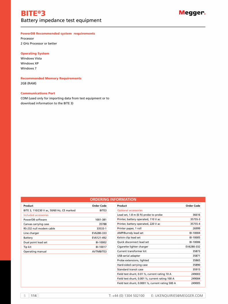
5 114 T: +44 (0) 1304 502100 E: [email protected]
PowerdB recommended system requirements
Processor
2 GHz Processor or better
Operating system
Windows Vista
Windows XP
Windows 7
recommended Memory requirements
2GB (RAM)
Communications Port
COM (used only for importing data from test equipment or to
download information to the BITE 3)
OrDErING INFOrMATION
Product Order Code
BITE 3, 110/230 V ac, 50/60 Hz, CE marked BITE3
Included accessories
PowerDB software 1001-381
canvas carrying case 35788
RS-232 null modem cable 33533-1
Line charger EV6280-333
Battery EV6121-492
Dual point lead set BI-10002
Tip kit BI-10017
operating manual AVTmBITE3
Product Order Code
optional accessories
Lead set, 1.8 m (6 ft) probe to probe 36616
Printer, battery operated, 110 V ac 35755-3
Printer, battery operated, 220 V ac 35755-4
Printer paper, 1 roll 26999
AmP/Burndy lead set BI-10004
Kelvin clip lead set BI-10005
Quick disconnect lead set BI-10006
cigarette lighter charger EV6280-332
current transformer kit 35873
USB-serial adapter 35871
Probe extensions, lighted 35865
Hard-sided carrying case 35890
Standard transit case 35915
Field test shunt, 0.01 ½, current rating 10 A 249003
Field test shunt, 0.001 ½, current rating 100 A 249004
Field test shunt, 0.0001 ½, current rating 500 A 249005
BITe®3Battery impedance test equipment

115 5WWW.mEggER.com
DescriptionPowerDB is a powerful software package that allows you
to organize and analyze the recorded battery test data.
PowerDB allows you to configure your BITE instrument as
well as transfer the data from the BITE to PowerDB. PowerDB
will then allow you to trend voltages, impedances, strap
resistances, cell temperature as well as specific gravity.
Power DB will also display the ripple current, float current,
ambient temperature as well as having a location for an IR
picture or a diagram or graphics. PowerDB allows you to use
red, yellow and green bands to quickly and easily compare
cells versus warning and failure limits. This allows you to
quickly and easily identify weak cells or old strings.
PowerDB comes in two version, the freeware version
PowerDB LITE and the full blown version PowerDB. In addition
to the features listed above PowerDB LITE also calculates
Baseline data, average impedance as well as average strap
values. PowerDB LITE also allows the user to input their own
logo, In addition PowerDB allows you to view just the charts
you wish to view as either line charts or bar charts.
The full blown PowerDB is a purchased copy that supports all
the functions of PowerDB LITE plus it operates with almost
all megger products and allows the user to merge data from
different products onto one report. The full blown PowerDB
will also allow users to create custom reports.
Using the BITE along with PowerDB will allow you to quickly
and easily locate individual poor cells within your string. This
will help provide longevity for the string. The BITE along with
PowerDB will also allow you to easily locate old strings that
are ready to be replaced. In addition the BITE along with
PowerDB will allow you to see how the batteries in your stings
are aging. This will allow you to predict their estimated life
span for easy budgeting.
SPECIFICATIONSSystem requirements
Processor 2 GHz Processor or better
operating systemWindows XPWindows VistaWindows 7
recommended system memory (rAM)
2 GB rAM
Communication port
CoM (used only for importing data from test equipment or to download
information to the BITe 3).
OrDErING INFOrMATIONProduct Order Code
PowerDB battery database management software
1001-3
PowerDBBattery database management software
PowerDB for use with BITE2/2P and BITE3
n organizes and manages battery data
n Allows analysis, comparison and trending of data
n Allows user to customize reports.
n Insert company logo and pictures of battery stings
n calculates baseline values
n Imports legacy ProActiv databases

5 116 T: +44 (0) 1304 502100 E: [email protected]
BITe optional Accessories
BITE accessoriesn Enhances the capabilities of th BITE product line
n Designed for unique application situations
n The right tools for battery testing
n Facilitates complete battery testing
DescriptionMegger offers a complete line of accessories to enhance the
capabilities of the BITE product line. Several are listed here, but
there are many others including extension cables, calibration
shunts, and more, which are not listed. Please contact us for
further information. Also, we are continually evaluating
additional products as interest arises.
ropeCTTM (Current transformer)
The RopeCT is a flexible, highly accurate current transformer
for measuring current flow in larger battery systems with
larger buss work. It comes in two lengths, 60 cm (24 in.) and
90 cm (36 in.) for 20 cm (8 in.) and 30 cm (12 in.) diameters,
respectively. Since it is flexible, it could form into an oval to
easily fit around most any buss work or intercell connection
configuration. The RopeCT is designed specifically for use with
the BITE2, BITE2P and BITE3. Check the Ordering Information
to select the right one.
Miniature 12 mm (1/2 in.) CT (Current transformer)
In some installations, it is difficult to attach the standard
50 mm (2 in.) CT due to the size limitations of the site or size
of the cable. To overcome this situation, Megger now offers
a 12 mm (1/2 in.) CT for smaller gauge wires and for tight
spaces.
Probe extensions
Probe extensions are available for most BITE models. They
are mounted on the probes of the BITE3 or on the Receiver
and Potential probe of the BITE2 and BITE2P. They are
excellent for reaching battery terminals and interconnectors
in cabinetized and racked batteries. They are also helpful for
reaching batteries on the top rack of a three-tier, two-row
rack. One set of probe extension kits consists of two
adapters, two 30 cm (12 in.) extensions and six tips.
Extensions are threaded for easy assembly. Simply remove
the extension and screw the tip into the adapter for normal
use. The other tips have a 90°, 135° (45°) and a 180° bend
for easy access to most battery configurations. The BITE3 has
snap-on adapters and slide-on/off extensions and tips
Digital hydrometer (with memory module)
The digital hydrometer accurately and quickly determines
specific gravity of flooded cells. Simply draw the electrolyte
into it; the specific gravity and temperature are determined
in five seconds. The data is downloaded to the data logger
memory module which can store up to eight tests of 256 cells
each. The stored data can be easily downloaded into any PC
using the PowerDB, Megger’s battery management software.
Bar code scanner
The bar code scanner is used to enter header and cell
information into the BITE2, and BITE2P. Once the information
is entered, it becomes a permanent part of the string’s and/or
cell’s record. It comes with a preprinted and laminated sheet
with alphanumeric bar codes and commands (such as “Enter”).
Bar code label printing software is available as an option.
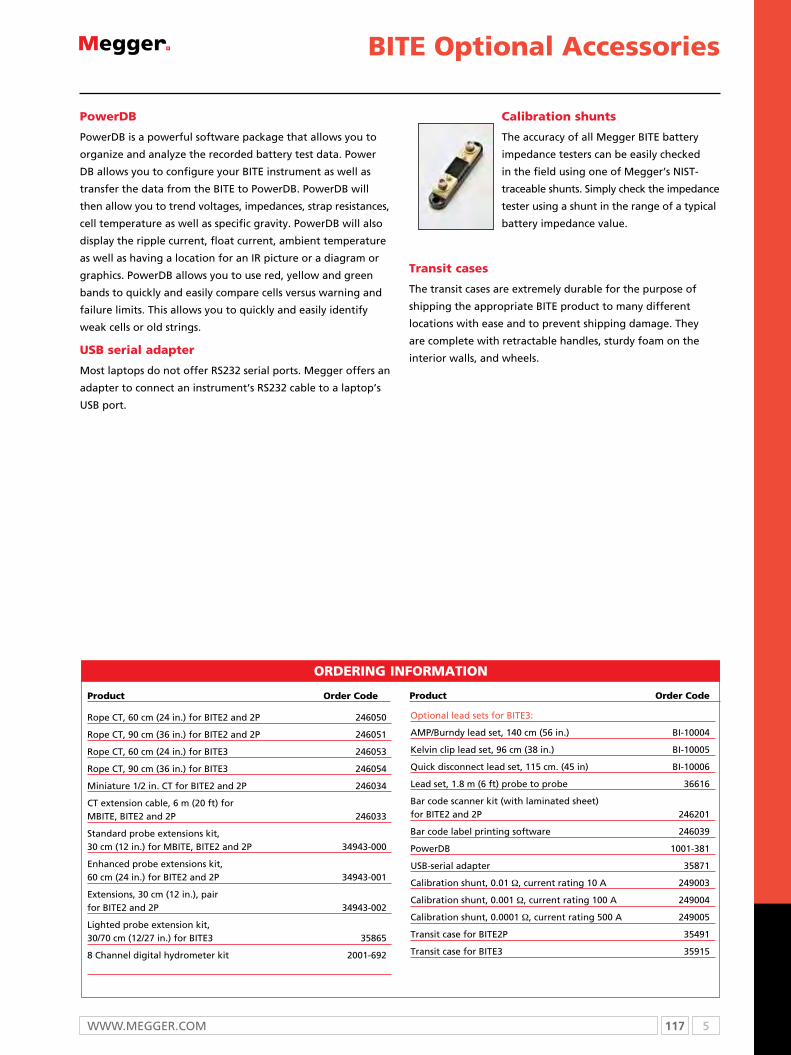
117 5WWW.mEggER.com
PowerDB
PowerDB is a powerful software package that allows you to
organize and analyze the recorded battery test data. Power
DB allows you to configure your BITE instrument as well as
transfer the data from the BITE to PowerDB. PowerDB will
then allow you to trend voltages, impedances, strap resistances,
cell temperature as well as specific gravity. PowerDB will also
display the ripple current, float current, ambient temperature
as well as having a location for an IR picture or a diagram or
graphics. PowerDB allows you to use red, yellow and green
bands to quickly and easily compare cells versus warning and
failure limits. This allows you to quickly and easily identify
weak cells or old strings.
USB serial adapter
Most laptops do not offer RS232 serial ports. Megger offers an
adapter to connect an instrument’s RS232 cable to a laptop’s
USB port.
Calibration shunts
The accuracy of all Megger BITE battery
impedance testers can be easily checked
in the field using one of Megger’s NIST-
traceable shunts. Simply check the impedance
tester using a shunt in the range of a typical
battery impedance value.
Transit cases
The transit cases are extremely durable for the purpose of
shipping the appropriate BITE product to many different
locations with ease and to prevent shipping damage. They
are complete with retractable handles, sturdy foam on the
interior walls, and wheels.
BITe optional Accessories
Optional lead sets for BITE3:
AMP/Burndy lead set, 140 cm (56 in.) BI-10004
Kelvin clip lead set, 96 cm (38 in.) BI-10005
Quick disconnect lead set, 115 cm. (45 in) BI-10006
Lead set, 1.8 m (6 ft) probe to probe 36616
Bar code scanner kit (with laminated sheet) for BITE2 and 2P 246201
Bar code label printing software 246039
PowerDB 1001-381
USB-serial adapter 35871
Calibration shunt, 0.01 Ω, current rating 10 A 249003
Calibration shunt, 0.001 Ω, current rating 100 A 249004
Calibration shunt, 0.0001 Ω, current rating 500 A 249005
Transit case for BITE2P 35491
Transit case for BITE3 35915
Product Order CodeProduct Order Code
OrderiNg iNfOrMatiON
Rope CT, 60 cm (24 in.) for BITE2 and 2P 246050
Rope CT, 90 cm (36 in.) for BITE2 and 2P 246051
Rope CT, 60 cm (24 in.) for BITE3 246053
Rope CT, 90 cm (36 in.) for BITE3 246054
Miniature 1/2 in. CT for BITE2 and 2P 246034
CT extension cable, 6 m (20 ft) for MBITE, BITE2 and 2P 246033
Standard probe extensions kit, 30 cm (12 in.) for MBITE, BITE2 and 2P 34943-000
Enhanced probe extensions kit, 60 cm (24 in.) for BITE2 and 2P 34943-001
Extensions, 30 cm (12 in.), pair for BITE2 and 2P 34943-002
Lighted probe extension kit, 30/70 cm (12/27 in.) for BITE3 35865
8 Channel digital hydrometer kit 2001-692

5 118 T: +44 (0) 1304 502100 E: [email protected]
optional Accessoriesfor Torkel
Cable set, GA-00554
TOrkEL Win PC softwaren Shows the complete voltage curve
n Last recorded time, voltage, current and discharged capacity
n Scroll window for all recorded values
n Remote control of ToRKEL
n Report functions
Cable set GA-00550
BS-8208X - TXL850 extra load

119 5WWW.mEggER.com

6 120 T: +44 (0) 1304 502100 E: [email protected]
Selection guide ......................................................................................... 121Technical information ................................................................................ 122CabaWin circuit breaker analysis software ................................................. 124EGIL circuit breaker analyser ...................................................................... 125TM1700 circuit breaker analyser system .................................................... 132TM1800 circuit breaker analyser system .................................................... 140SDRM202 static/dynamic resistance measurement..................................... 147VIDAR vacuum interrupter tester ............................................................... 149B10E AC/DC voltage power supply ........................................................... 152MS-2A circuit breaker with overcurrent relay test system ........................... 154OCR-8015 and OCR-9150 automatic oil circuit recloser test set................. 156Optional accessories .................................................................................. 159
6
Circuit breakers are one of the critical “safety-valves” of electrical systems, thorough maintenance procedures are essential to maintain maximum reliability to ensure they operate when required.
Effective circuit breaker maintenance requires well-organized, accurate testing. The ability to accurately compare circuit breaker tests with previous test results is essential. It is, therefore, imperative to conduct tests in exactly the same way and under the same conditions as those conducted earlier.
Circuit Breaker Test
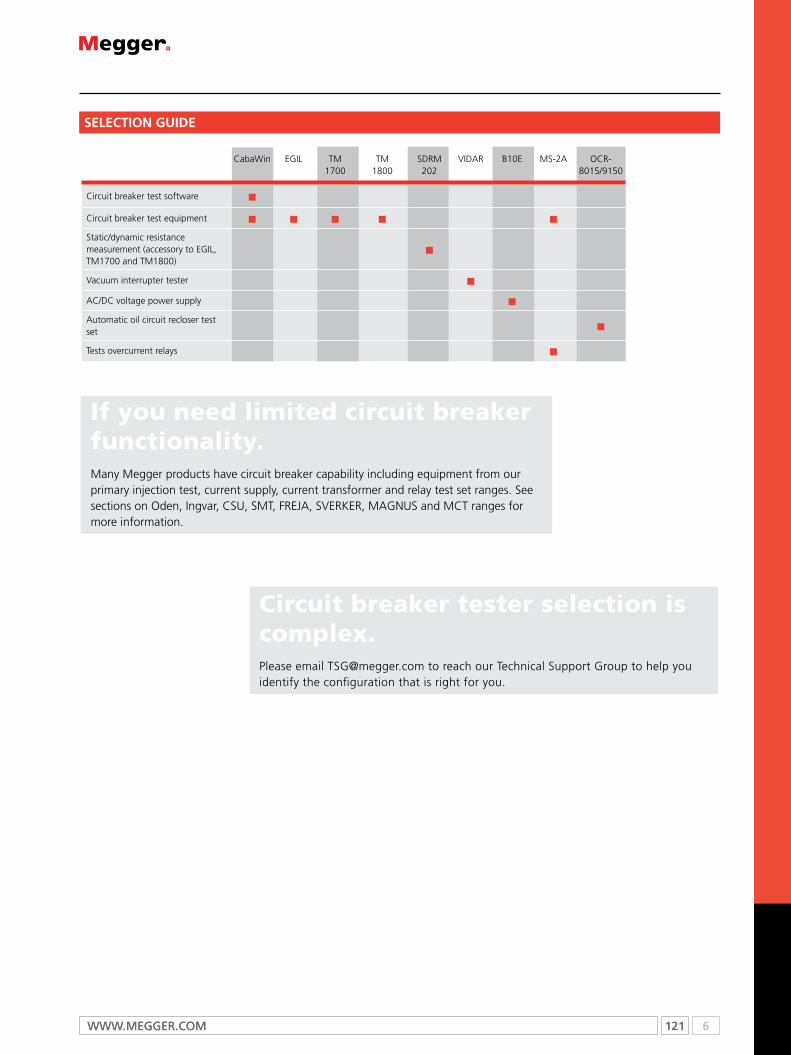
121 6WWW.mEggER.comWWW.mEggER.com
SELECTION GUIDE
CabaWin EGIL TM1700
TM1800
SDRM202
VIDAR B10E MS-2A OCR-8015/9150
Circuit breaker test software n
Circuit breaker test equipment n n n n n
Static/dynamic resistance measurement (accessory to EGIL, TM1700 and TM1800)
n
Vacuum interrupter tester n
AC/DC voltage power supply n
Automatic oil circuit recloser test set n
Tests overcurrent relays n
Circuit breaker tester selection is complex.Please email [email protected] to reach our Technical Support Group to help you identify the configuration that is right for you.
If you need limited circuit breaker functionality.Many Megger products have circuit breaker capability including equipment from our primary injection test, current supply, current transformer and relay test set ranges. See sections on Oden, Ingvar, CSU, SMT, FREJA, SVERKER, MAGNUS and MCT ranges for more information.

6 122 T: +44 (0) 1304 502100 E: [email protected]
Testing circuit breakers
High voltage circuit breakers are extremely important for the function of modern electric power supply systems. The breaker is the active link that ultimately has the role of operating the primary circuit when a fault has occurred. The breaker has to perform its duty within a few milliseconds, after months, perhaps years of idly standing by.
Since RCM and condition based maintenance have become the established strategies for most owners and operators of electric power supply systems, the need for reliable and accurate field test instruments is obvious.
Ever since the introduction of the first microprocessor based breaker analyzer in 1984, many new user requirements have lead Megger to provide test engineers in the field with effective tools for determining the status of circuit breakers.
Different maintenance strategies
If a maintenance strategy that is strictly corrective is adopted, no attempts are made to deal with a developing circuit breaker fault before it becomes fatal. This does not ensure the reliable supply of electric power that consumers are entitled to expect. Short-term savings in maintenance costs will soon be eaten up by the cost of the damage and the cost of correcting a fault.
Preventive maintenance - which includes inspection, testing, overhauls and modifications - is a strategy that is encountered more frequently.
In time interval-based maintenance, a number of specific measures are taken at predetermined times, regardless of the conditions under which a circuit breaker operates. If this method is applied too strictly, however, it may lead to needless intervention. Disassembling a circuit breaker that has no faults entails needless expense, and it does not improve reliability.
Condition-based maintenance is being used more and more. Here, you ascertain the condition of a circuit breaker through testing and inspection. The results, supplemented with statistical data and cumulative experience, are then used to plan maintenance for the circuit breaker in question. The breaker’s need for maintenance is based less on time than on the conditions to which it is exposed, how frequently it operates and its environment. Condition-based maintenance provides excellent opportunities to improve reliability and cut costs, but it requires effective diagnostic methods. Many circuit breakers provide longer service lives than expected. If you can ascertain that a breaker is in good condition, you can continue to use it rather than replace it. Here too, however, effective diagnostic methods are of prime importance.
Circuit breaker testing
Before a new circuit breaker is delivered, it is tested at the factory. After it has been installed, it is submitted to a commissioning test before being taken into service. Thereafter, it is inspected and tested on different occasions. Usually, a circuit breaker has to be taken out of service in order to test it.
The following parameters are often tested on a circuit breaker: closing time, opening time, resistance of the main contacts and synchronization of contact operation. Contact travel and speed are also tested (as recommended in the IEC62271-100 and IEEER C37.09 standard and other literature).
Some other methods for circuit breaker diagnostics are dynamic resistance and vibration testing. Also, checks are made to see that the solenoids and latches operate properly. This is done by measuring the lowest breaker operating voltage and checking the shape of the coil current curve.
Measured values are compared with limit values specified by the manufacturer or values that have been arrived at by the maintenance organization through experience. In many cases, a “fingerprint” consisting of different measurements taken when a breaker is new is compiled. This fingerprint can then be used as a reference for subsequent measurements.
Any change that is found clearly indicates a change in the breaker’s condition.
Application
Timing measurements
Simultaneous measurements within a single phase are important in situations where a number of contacts are connected in series. Here, the breaker becomes a voltage divider when it opens a circuit. If the time differences are too great, the voltage becomes too high across one contact, and the tolerance for most types of breakers is less than 2 ms.
The time tolerance for simultaneous measurements between phases is greater for a 3-phase power transmission system running at 50 Hz since there is always 3.33 ms between zero-crossovers. Still, the time tolerance is usually specified as less than 2 ms, even for such systems.
It should also be noted that breakers that perform synchronized breaking must meet more stringent requirements in both of the previously stated situations.
There are no generalized time limits for the time relationships between main and auxiliary contacts, but it is still important to understand and check their operation. The purpose of an auxiliary contact is to close and open a circuit. Such a circuit might enable a closing coil when a breaker is about to perform a closing operation and then open the circuit immediately after the operation starts, thereby preventing coil burnout.
The “a” contact must close well in advance of the closing of the main contact. The “b” contact must open when the operating mechanism has released its stored energy in order to close the breaker. The breaker manufacturer will be able to provide detailed information about this cycle.
Motion measurements
A high-voltage breaker is designed to interrupt a specific short-circuit current, and this requires operation at a given speed in order to build up an adequate cooling stream of air, oil or gas (depending on the type of breaker). This stream cools the electric arc sufficiently to interrupt the current at the next zero-crossover. It is important to interrupt the current in such a way that the arc will not re-strike before the breaker contact has entered the so-called damping zone.
Speed is calculated between two points on the motion curve. The upper point is defined as a distance in length, degrees or percentage of movement from a) the breaker’s closed position, or b) the contact closure or contact-separation point. The time that elapses between

123 6WWW.mEggER.com
these two points ranges from 10 to 20 ms, which corresponds to 1-2 zero-crossovers.
The distance throughout which the breaker’s electric arc must be extinguished is usually called the arcing zone. From the motion curve, a velocity or acceleration curve can be calculated in order to reveal even marginal changes that may have taken place in the breaker mechanics.
Damping is an important parameter for the high energy operating mechanisms used to open and close a circuit breaker. If the damping device does not function satisfactorily, the powerful mechanical strains that develop can shorten breaker service life and/or cause serious damage. The damping of opening operations is usually measured as a second speed, but it can also be based on the time that elapses between two points just above the breaker’s open position.
Coil currents
These can be measured on a routine basis to detect potential mechanical and/or electrical problems in actuating coils well in advance of their emergence as actual faults. The coil’s maximum current (if current is permitted to reach its highest value) is a direct function of the coil’s resistance and actuating voltage. This test indicates whether or not a winding has been short-circuited.
When you apply a voltage across a coil, the current curve first shows a straight transition whose rate of rise depends on the coil’s electrical characteristic and the supply voltage. When the coil armature (which actuates the latch on the operating mechanism’s energy package) starts to move, the electrical relationship changes and the coil current drops. When the armature hits its mechanical end position, the coil current rises to the current proportional to the coil voltage. The auxiliary contact then opens the circuit and the coil current drops to zero with a current decay caused by the inductance in the circuit (points 8-9).
The peak value of the first, lower current peak is related to the fully saturated coil current (max current), and this relationship gives an indication of the spread to the lowest tripping voltage. If the coil was to reach its maximum current before the armature and latch start to move, the breaker would not be tripped. It is important to note, however, that the relationship between the two current peaks varies, particularly with temperature. This also applies to the lowest tripping voltage.
Dynamic resistance measurement (DRM)
A circuit breaker will have the arcing contact wear by normal operation as well as when breaking short-circuit currents. If the arcing contact is too short or otherwise in bad condition, then the breaker soon becomes unreliable. Main contact surfaces can be deteriorated by arching resulting in increased resistance, excessive heating and in worst-case explosion.
The main contact resistance is measured dynamically over an open or close operation in DRM. With DRM measurement the arcing contact length can be reliably estimated. The only real alternative in finding the length of the arcing contact is dismantling the circuit breaker.
A reliable DRM interpretation requires high test current and a circuit breaker analyzer with good measurement resolution. Testing with DualGround is applicable.
Vibration analysis
Vibration analysis is a non-invasive method using an acceleration sensor without moving parts. The breaker can stay in service during the test. A single Open-Close operation is all that is required for the measurement. The first operation is different compared to the seco and third because of corrosion and other metal to metal contact issues. Vibration is an excellent method to capture the first operation after long time in the same position.
The analysis compares the vibration time series with earlier taken reference. The vibration method detects faults that can hardly be indicated with conventional methods. But if conventional data such as contact time, travel curve, coil current and voltage are available in addition to the vibration data even more precise condition assessment is possible. The vibration data is stored together with available conventional data.
The Vibration method is published in CIGRE and IEEER papers. Since about 10 years is it utilized in the industry for testing all kind of breakers from 400 kV distribution to industrial sites. The method was first established on the Scandinavian market. Vibration can be performed under very safe manners for the test technician as both sides can be grounded throughout the test. Also less climbing is required since no access to the breaker contact system is needed, the acceleration sensor is easily mounted on the breaker. Testing with DualGround is applicable.

6 124 T: +44 (0) 1304 502100 E: [email protected]
CabaWincircuit breaker analysis software
CabaWinn Pre-defined standard test plans for quick and easy
testing
n Detailed circuit breaker analysis by accurate comparison
with historical test results
n graphical display of a variety of measurements and
timing test results
n convenient report generation with mS Word or
List&Label
n compatibility with Tm1800, Tm1600/mA61/Tm1700 and
EgIL units
DescriptionEffective circuit breaker maintenance requires well-organized, accurate testing. The ability to accurately compare circuit breaker tests with previous test results is essential. It is, therefore, imperative to conduct tests in exactly the same way and under the same conditions as those conducted earlier. comparison can then provide a clear picture of any deviations and changes, thereby indicating whether or not the circuit breaker should be kept in operation or taken out of service for further investigation.
comprehensive, accurate testing also requires analytical tools and efficient reporting. It must be possible to validate test results in detail and then easily compare them with other test results.
The cABA WinTm (computer-aided Breaker Analysis) program has earned a benchmark reputation in circuit breaker analysis. Test results from earlier versions of cABA are upwards compatible to cABA Win.
cABA Win can be used with megger breaker analysers Tm1800, Tm1600/mA61/Tm1700 and EgIL. cABA Win organizes all the test tasks and ensures that measurements are conducted in the same way for each object being tested. cABA Win saves the results and generates the report. In the analysis section, the user can work with a number of graphic
windows, compare different measurements by overlaying one graph on another in the same display, and use cursors and powerful zoom functions for detailed analysis. cABA Win simplifies testing and ensures the quality of the test procedure.
ApplicationTest planscABA Win can be used for all breaker testing applications, ranging from simple time measurement to dynamic resistance and vibration measurements. A circuit breaker is defined before it is tested the first time. All of the entered data is kept together. This enables cABA Win to guide the user through the test procedure in exactly the same way each time the breaker is tested, regardless of who did the original testing. The result is efficiency gains throughout the test process and more accurate results. Precise comparisons can be confidently made from one test to the next. All of the test and circuit breaker data is saved together with the breaker’s unique test plan. It is also possible to enter the results of manually conducted tests, and to enter separate comments for the breaker regarding the test in question. Each breaker is given a unique identity by means of four individually user-defined fields. After being organized on the basis of individual circuit breakers and individual tests, the data can be stored in a database. A breaker specific test plan is automatically created, based on the specified test and breaker data. The test plan controls the individual measurements, the test points that are to be used, the transducers connected to the different measurement channels, and the parameters that are to be calculated. The test plan also specifies the data that is to be presented graphically and how the results are to be reported.
OrDErING INfOrmATIONProduct Order code
CABA Win
For TM1800 and TM1700 Incl. Ethernet cross-over cable CG-8000X
CABA Win
For TM1600 Incl. fiberoptics and USB interface BL-8203X
CABA Win
For EGIL Incl. USB cable BL-8204X
CABA Win upgradeUpgrade to latest version CG-8010X

125 6WWW.mEggER.com
SPECIfICATIONS
EGILcircuit breaker analyser
EGILn Suitable for testing timing and travel on all circuit
breakers with single interrupter per phase
n Extremely easy-to-use and reliable
n Two separate timing channels for measurement of
auxiliary contacts
n Analog measurement channels for travel transducers or
general voltage/current measurements
n Static and dynamic resistance measurements along with
the SDRm201 optional accessory
DescriptionEgIL™, which incorporates benefits gained from experience with our larger instrument, is intended for circuit breakers with one contact per phase. Smaller and simpler, EgIL is equally versatile – and EgIL’s price makes it attractive to small power plants. moreover, it provides an ideal supplementary instrument for maintenance departments at large power companies.
EgIL is designed to test circuit breakers having one main contact per phase. Its three time channels are connected together on one side. Events at parallel contacts equipped with pre-insertion resistors are recorded and displayed simultaneously. There are two separate time channels for measurement of auxiliary contacts. To simplify on-site hookup, EgIL comes with ready-made multi-cable sets for both main and auxiliary contacts.
coil currents are measured automatically and presented together with other readings immediately after testing on the display window or via the built-in printer. EgIL is easy to use – a built-in sequencer (program unit) sets the instrument automatically for the next sequential breaker operation.
Intended primarily for measuring travel (motion), the optional analog input channel finds many other uses as well. If this channel is not installed, all associated menu commands are hidden.
EgIL with the SDRm option together with the SDRm accessory enables static and dynamic resistance measurements.
EgIL can also be equipped with an optional USB interface for communication with a Pc and the cABA Win™ circuit Breaker Analysis Software.
SpecificationsSpecifications are valid at nominal input voltage and an ambient temperature of +25 °C, (77 °F). Specifications are subject to change without notice.
EnvironmentApplication field The instrument is intended for use
in medium-voltage substations and industrial environments.
Temperature
Operating 0 °C to +50 °C (32 °F to +122 °F)
Storage & transport -40 °C to +70 °C (-40 °F to +158 °F)
Humidity 5% – 95% RH, non-condensing
CE markingEMC 2004/108/EC
LVD 2006/95/EC
GeneralMains voltage 115 / 230 V AC (switchable), 50 / 60 Hz
Power consumption 100 VA (max)
Dimensions
Instrument 360 x 210 x 190 mm (14.2” x 8.3” x 7.5”)
Transport case 420 x 300 x 230 mm (16.5” x 11.8” x 9.0”)
Weight 6.3 kg (14 lbs). 10 kg (22 lbs) with accessories and transport case
Display LCD
Available languages English, German, French, Spanish, Swedish
measurement sectionTime measurement
Measurement time 1 to 100 s
Resolution 0.1 to 10 ms
Number of channels 3 with common ground
Time base inaccuracy 0.05% of the reading ± resolution
Status thresholds
Closed <10 Ω ±20%
Resistor 10 Ω ±20% to 3 kΩ ±20%
Open > 3 kΩ ±20%
Open circuit voltage 24 V ±20%
Short circuit current 100 mA ±20%
AUX 1&2
Number of channels 2, galvanically isolated
Contact-sensing (Dry)
Status thresholds
Closed < 600 Ω ±30%
Open > 600 Ω ±30%
Open circuit voltage 20 V ±20% DC
Short circuit current 25 mA ±20%
Voltage sensing (Wet)
Status thresholds
Open indication <8 V (polarity insensitive)
Close indication >13 V (polarity insensitive)
Working voltage 250 V AC / DC
SPECIfICATIONS
6 126 T: +44 (0) 1304 502100 E: [email protected]
EGILcircuit breaker analyser
Current measurement
Range ±25 A per channel
Resolution 25 mA
Inaccuracy 1% of the reading ±100 mA
Working voltage 250 V AC / DC
Breaker operationSequences C, O, C-O, O-C, O-C-O
Continuous current 5 A
Max current 25 A during 300 ms, rest time 1 min
Contact function Two independent control functions
Contact characteristics Non bouncing, closing time max. 0.1 ms
Make/Break capacity 25 A, 250 V (AC or DC) per contact function
Start breaker operation By rotary switch
Pulse length Adjustable in steps of 10 ms
Pulse delay Adjustable in steps of 10 ms
Working voltage 250 V AC / DC
motion (optional)Number of channels 1 independent
Max cable length 10 m (33 ft)
InputRange -4 V to +4 V
Resolution 2 mV
Inaccuracy 1% of the measurement range
Transducer resistance 1 kΩ to 5 kΩ
Input impedance 150 kΩ
OutputOpen circuit voltage 4,095 V ±4 mV
Short circuit current 115 mA
PrintoutType of printout Graphic and numeric
Printer Thermal printer with fixed print head
Graphic resolution 8 dots/mm – 203 dpi
Paper width 114 mm (4.5”)
127 6WWW.mEggER.com
Product Order code
EGIL Basic unitIncl:
Time measurement cables GA-00160, GA-00170Cable set for sequencer GA-00082Transport case GD-00190
BM-19090
Egil with analog input channel and USB portIncl:
CABA Win BL-8206XTime measurement cables GA-00160, GA-00170Cable set for sequencer GA-00082Transducer cable XLR-open 1 m (3.2 ft)
GA-00041
Transducer cable XLR-XLR 7.5 m (24.6 ft)
GA-00042
Transport case GD-00190
BM-19093
Egil with SDRM option and USB portIncl:
CABA Win BL-8206XTime measurement cables GA-00160, GA-00170Cable set for sequencer GA-00082Transducer cable XLR-open 1 m (3.2 ft)
GA-00041
Transducer cable XLR-XLR 7.5 m (24.6 ft)
GA-00042
Transport case GD-00190
BM-19095
Upgrade
Upgrade of EGIL can be done, please contact your nearest distributor for part number and price.
Optional accessories
CABA WinCircuit breaker analysis software Incl. USB cable BL-8206X
SDrm201 CG-90250
Extension cables for SDRm201
10 m (33 ft) extension GA-12810
7.5 m (24.6 ft) extension GA-12815
Transducers – Linear
TLH 500 XB-30020
LWG 225 XB-30117
TS 150 XB-30030
TS 25 XB-30033
Transducers – rotary
Novotechnic IP6501 XB-31010
Flex coupling for IP6501 XB-39030
Transducer mounting kits
Universal kits
Rotary transducer mounting kit For transducers XB-31010 and XB-39130 XB-51010
Universal transducer mounting kit for linear and rotary transducers XB-51020
Ready-to-use-kits – Rotary
Incl. transducer XB-31010, mounting kit XB-51010 XB-71010
Transducer mounting accessories
Universal support XB-39029
OrDErING INfOrmATIONProduct Order code
Switch magnetic base XB-39013
Cables
cable reel20 m (65.5 ft), 4 mm stackable safety plugs
Black GA-00840
Red GA-00842
Yellow GA-00844
Green GA-00845
Blue GA-00846
cable sets The cable sets consist of 8 cables with clamps and 4 mm stackable safety plugs
8 x 5 m, (16.4 ft) GA-00231
8 x 10 m, (32.8 ft) GA-00241
8 x 15 m, (49.2 ft) GA-00251
Extension cables, XLR female to male
For analog input, 10 m (32.8 ft) GA-01005
For time measurement of main contacts, 10 m (32.8 ft) GA-00150
open analog cableFor customized analog transducer connection
GA-01000
XLR to 4 mm safety plugsFor customized analog transducer connection
GA-00040
Other
VD401Voltage divider, ratio 400/1 (for TM1600 and EGIL with analog channel)
BL-90070
Thermopaper, 114 mm, 30 m GC-00030
cable organizer, Hook and loop fastener, 10 pcs AA-00100
EGILcircuit breaker analyser
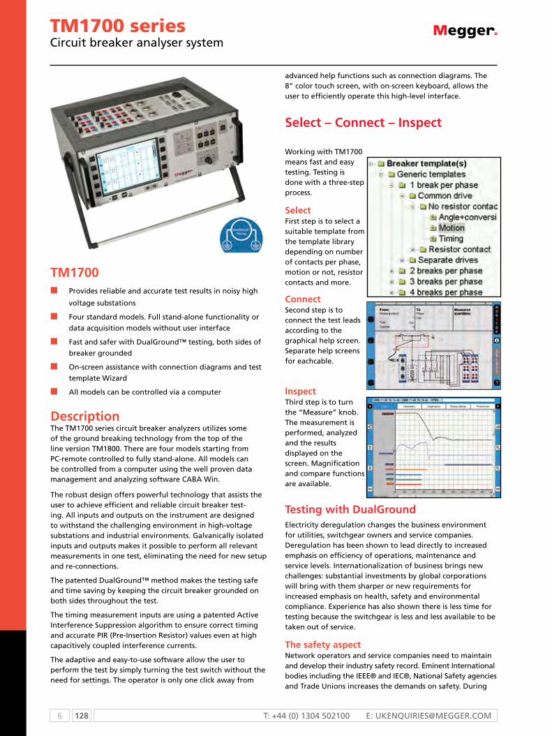
6 128 T: +44 (0) 1304 502100 E: [email protected]
TM1700 seriescircuit breaker analyser system
Tm1700n Provides reliable and accurate test results in noisy high
voltage substations
n Four standard models. Full stand-alone functionality or
data acquisition models without user interface
n Fast and safer with Dualground™ testing, both sides of
breaker grounded
n on-screen assistance with connection diagrams and test
template Wizard
n All models can be controlled via a computer
DescriptionThe TM1700 series circuit breaker analyzers utilizes some of the ground breaking technology from the top of the line version TM1800. There are four models starting from PC-remote controlled to fully stand-alone. All models can be controlled from a computer using the well proven data management and analyzing software CABA Win.
The robust design offers powerful technology that assists the user to achieve efficient and reliable circuit breaker test-ing. All inputs and outputs on the instrument are designed to withstand the challenging environment in high-voltage substations and industrial environments. galvanically isolated inputs and outputs makes it possible to perform all relevant measurements in one test, eliminating the need for new setup and re-connections.
The patented Dualground™ method makes the testing safe and time saving by keeping the circuit breaker grounded on both sides throughout the test.
The timing measurement inputs are using a patented Active Interference Suppression algorithm to ensure correct timing and accurate PIR (Pre-Insertion Resistor) values even at high capacitively coupled interference currents.
The adaptive and easy-to-use software allow the user to perform the test by simply turning the test switch without the need for settings. The operator is only one click away from
advanced help functions such as connection diagrams. The 8” color touch screen, with on-screen keyboard, allows the user to efficiently operate this high-level interface.
Select – Connect – Inspect
Working with Tm1700 means fast and easy testing. Testing is done with a three-step process.
SelectFirst step is to select a suitable template from the template library depending on number of contacts per phase, motion or not, resistor contacts and more.
ConnectSecond step is to connect the test leads according to the graphical help screen. Separate help screens for eachcable.
InspectThird step is to turn the “measure” knob. The measurement is performed, analyzed and the results displayed on the screen. magnification and compare functions are available.
Testing with DualGroundElectricity deregulation changes the business environment for utilities, switchgear owners and service companies. Deregulation has been shown to lead directly to increased emphasis on efficiency of operations, maintenance and service levels. Internationalization of business brings new challenges: substantial investments by global corporations will bring with them sharper or new requirements for increased emphasis on health, safety and environmental compliance. Experience has also shown there is less time for testing because the switchgear is less and less available to be taken out of service.
The safety aspectNetwork operators and service companies need to maintain and develop their industry safety record. Eminent International bodies including the IEEE® and IEc®, National Safety agencies and Trade Unions increases the demands on safety. During

129 6WWW.mEggER.com
TM1700 seriescircuit breaker analyser system
the deregulation safety regulations have been clarified and the application of existing rules has been tightened. Keeping a good safety record is becoming a crucial asset to attract investors and customers.
In all substations the capacitive coupling from live high voltage conductors induce harmful/lethal currents in all parallel conductors. grounding both sides of the test object will lead the induced current to earth and provide a safe area for the test personnel. See diagrams below.
Both sides groundedThe best way to provide safety in circuit breaker testing is to keep both sides of the circuit breaker grounded throughout the test. This will also make the test faster and easier. Testing personnel should spend the minimum time in the substation and their focus should be the test rather than the equipment.
The Dualground™ testing method is available for all tests on all circuit breakers.
With only one side grounded the induced current can reach values high enough to be harmful or lethal for humans.
Testing is much safer using the DCm module and DualGround.
contact resistance
mJÖLNEr / SDrm202
Timing Tm1700 with DCm motion Tm1700 SDRm Tm1700 with
SDrm202 Vibration CABA Win Vibration
/ SCA606
Equipment and methods that support DualGround™ test-ing are associated with the DualGround symbol. This symbol certifies the use of ground-breaking technology and methods that enable a safe, fast and easy workflow with both sides grounded throughout the test.
Conventional vs. DualGroundSite preparation (isolate work area, apply safety ground, issue permit to work)
Site preparation (isolate work area, apply safety ground, issue permit to work)
Hook up test equipment. Issue sanction for test
Hook up test equipment. Issue sanction for test
Authorised person removes the ground
Risky step left out
Perform testing Safe testing with both sides grounded
Authorised person applies ground
Risky step left out
Cancel sanction for test. Discon-nect test equipment
Cancel sanction for test. Dis-connect test equipment
Site closing (cancel permit to work, disconnect ground)
Site closing (cancel permit to work, disconnect ground)

6 130 T: +44 (0) 1304 502100 E: [email protected]
Specifications TM1700-seriesGeneralSpecifications are valid after 30 minutes warm up time. System time base drift 0.001% per year. Specifications are subject to change without notice.
EnvironmentApplication field For use in high-voltage substations and
industrial environments
Temperature
Operating -20 °C to +50 °C (-4 °F to +122 °F)
Storage & transport -40 °C to +70 °C (-40 °F to +158 °F)
Humidity 5% – 95% RH, non-condensing
CE-markingEMC 2004/108/EC
LVD 2006/95/EC
GeneralMains input (nominal) 100 – 240 V AC, 50 / 60 Hz
Power consumption 200 VA (max)
Dimensions 515 x 173 x 452 mm (20.3” x 6.8” x 17.8”)
Weight 12 kg (26.5 lbs)
External inputTrIG INVoltage modeInput range 0 – 250 V AC / DC
Threshold level User configurable in software in steps of 1 V
Contact modeOpen circuit voltage 30 V DC ±15%
Short circuit current 10 – 40 mA
Threshold level 1 – 2 kΩ
External outputsDC OUTGeneral voltage source 12 V ±10%, short circut protection 1.7 A
Drm only for SDrm202 and Drm1800Voltage modeOutput Voltage 12 V DC ±10%
Short circuit protection PTC 750 mA
Switching current < 750 mA, resistive load
Communication interfacesUSB Universal Serial Bus ver. 2.0
Ethernet 100 base-Tx Fast Ethernet
HmI, Human-machine interface CABA Local Circuit breaker analyzing software
Available languages English, French, German, Spanish, Swedish. Translation kit available
Display High brightness SVGA 800x600, Touch screen
Diagonal size 21 cm (8”)
Keyboard On screen
Control section (1 or 2)GeneralNo. of channels 3
Time base inaccuracy ±0.01% of reading ±1 sample interval
Max. sample rate 40 kHz
Measurement time 200 s at 10 kHz sample rate,
Non-bouncing switchMax current 60 A AC / DC, pulse ≤100 ms
Duration User configurable in steps of 1 ms
Delay User configurable in steps of 1 ms
Current measurementMeasurement range 0 to ±80 A AC / DC
Resolution 16 bits
Inaccuracy ±2% of reading ±0.1% of range
External current measurementCT
Max input ±1 V
Scaling 100 A / 1 V
Range ±80 A V / ±0.8 V
Voltage measurementMeasurement range 0 – 250 V AC / DC
Resolution 12 mV
Inaccuracy ±1% of reading ±0.1% of range
Timing m/r section (1)GeneralNo. of channels 6
Time base inaccuracy ±0.01% of reading ±1 sample interval
Min. resolution 0.05 ms
Max. sample rate 40 kHz
Measurement time 200 s at 20 kHz sample rate
Timing of main and resistive contactsOpen circuit voltage 6 V or 26 V ±10% (Toggling at every
second sample)
Short cicuit current 9.7 mA or 42 mA ±10%
Status thresholdMain Closed < 10 Ω < Open
Main and Resistor Main < 10 Ω <PIR < 10 kΩ < Open
PIr resistance measurementSupported PIR types Linear PIR
Measurement range 30 Ω – 10 kΩ
Inaccuracy ±10% of reading ±0.1% of range
Voltage measurementMeasurement ranges ±50 Vpeak, ±15 Vpeak, ±0.5 Vpeak
Resolution 16 bits
Inaccuracy ±1% of reading ±0.1% of range
Analog section (none, 1 or 2)GeneralNo. of channels 3 isolated channels
Time base inaccuracy ±0.01% of reading ±1 sample interval
Max. sample rate 40 kHz
Measurement time 200 s at 10 kHz sample rate
Transducer resistance 500 Ω – 10 kΩ at 10 V output
OutputVoltage output 10 V DC ±5%, 24 V DC ±5%
Max. output current 30 mA
Current measurementMeasurement range ±22 mA
Resolution 16 bits
Inaccuracy ±1% of reading ±0.1% of range
TM1700 seriescircuit breaker analyser system

131 6WWW.mEggER.com
Digital sectionGeneralNo. of channels 6
Supported types Incremental transducers, RS422
Time base inaccuracy ±0.01% of reading ±1 sample interval
Max. sample rate 40 kHz
Measurement time 200 s at 10 kHz sample rate
OutputVoltage 5 V DC ±5% or 12 V DC ±5%
Max. output current 200 mA
Digital inputRange ±32000 pulses
Resolution 1 pulse
Inaccuracy ±1 pulse
Timing Aux sectionGeneralNo. of channels 6 isolated channels
Time base inaccuracy ±0.01% of reading ±1 sample interval
Max. sample rate 40 kHz
Measurement time 200 s at 10 kHz sample rate
Voltage modeInput voltage range 0 – ±250 V AC / DC
Status threshold ±10 V
Inaccuracy ±0.5 V
Contact modeOpen circuit voltage 25 – 35 V
Short circuit current 10 – 30 mA
Status threshold Closed < 100 Ω, Open >2 kΩ
Voltage measurementInput voltage range 0 – 250 V AC / DC
Measurement ranges ±10 V DC, 0 – 250 V AC / DC
Resolution 16 bits
Inaccuracy
250 V range ±1% of reading ±0.1% of range
10 V range ±0.1% of reading ±0.01% of range
TM1700 seriescircuit breaker analyser system

6 132 T: +44 (0) 1304 502100 E: [email protected]
TM1700 – Models
Tm1710
Including: Control 3 ch. (Auxiliary 3 ch.) Timing M/R 6 ch. Digital 6 ch. CABA Win
Optional: Analog 3 ch., DCM 6 ch.
Tm1720
Including: Control 6 ch. (Auxiliary 6 ch.) Auxiliary 6 ch. Timing M/R 6 ch. Digital 6 ch. CABA Win
Optional: Analog 3 ch., DCM 6 ch.
Tm1750
Including: Control 6 ch. (Auxiliary 6 ch.) Auxiliary 6 ch. Timing M/R 6 ch. Digital 6 ch. CABA Win
front panel
front panel
front panel
Top panel
Top panel
Top panel

133 6WWW.mEggER.com
Tm1760
Including: Control 6 ch. (Auxiliary 6 ch.) Auxiliary 6 ch. Timing M/R 6 ch. Digital 6 ch. Analog 3 CABA Win
Optional: Analog 3 ch., DCM 6 ch.
Top panelfront panel
6 134 T: +44 (0) 1304 502100 E: [email protected]
Item Description Order Code
Software and application kits
CABA Win – Circuit breaker analysis software
CABA Win incl. Ethernet cross-over cable CG-8000X
CABA Win upgrade
Upgrade to latest versionCG-8010X
Vibration analysis
Vibration kit The Vibration kit extends TM1800 and CABA Win with the equipment and software required for recording and ana-lyzing vibration signals at a circuit breaker. The kit includes the signal conditioning unit SCA606, the software CABA Win vibration and one vibration channel. The vibration solution can be extended up to 6 channels. BL-13090
Vibration channel
Additional vibration channel to be used together with the vibration kit. Each vibration channel includes accelerometer, accelerometer adapter, cables to SCA606 and cables to TM1700-series. XB-32010
Synchronized switching relay test kit
SSR kit Incl. accessories, software and cables (delivered in transport case) CG-91200
1:st trip kits For single operating mechanism BL-90700
For three operating mechanisms BL-90710
DCM (Dynamic Capacitance Measurement)
DCM1700 The DCM1700 is used for timing using the DualGround™ method. Safe testing with both sides grounded.
DCM1700 3 ch Kit for 3-channels DualGround™ Timing BL-59190
DCM1700 6 ch Kit for 6-channels DualGround™ Timing BL-59192
SDRM (Static and Dynamic Resistance Measurement)
SDRM202 The SDRM202 uses new technology, patent pending, with ultra capacitors. The current output is up to 220 A from a box that weighs only 1.8 kg (4 lbs). The weight of the current cables is also low because the SDRM202 is placed very close to the circuit breaker. Timing M/R measurement can be done with the same hook-up CG-90200
SDRM202 Pack of 3 units
Pack for CB with 2 Breaks / PhaseCG-90230
Extension cable SDRM202
7.5 m (24 ft) GA-12815
10 m (33 ft)GA-12810
Item Description Order Code
Transducers
Linear – Analog
TLH 500 500 mm (20”) travel Incl. cable 0.5 m (20”) XB-30020
LWG 225 225 mm (9”) travel Incl. cable 0.5 m (20”) XB-30117
TS 150 150 mm (5.9”) travel Incl. cable 1.0 m (3.3 ft) XB-30030
TS 25 25 mm (1”) travel Incl. cable 1.0 m (3.3 ft) XB-30033
Linear – Digital
TP1 300 300 mm (11.8”) travel Incl. cable 10 m (33 ft) XB-39140
TP1 500 500 mm (17.7”) travel Incl. cable 10 m (33 ft) XB-39150
Link 300 mm (11.8”) for position marker XB-39193
The above transducers are also available in other lengths, please contact Megger for information.
Rotary - Analog
Novotechnic IP6501
Incl. cable 1 m (3.3 ft), 6 mm Flex coupling, Hexagon wrench XB-31010
Flex coupling For IP6501, shaft diam. 6 mm XB-39030
Rotary – Digital
Baumer BDH16.05A3600-LO-B Incl. cable 10 m (33 ft), 10/6 mm Flex coupling, Hexagon wrench XB-39130
Transducer mounting kits
Universal kits
Rotary trans-ducer mounting kit
For transducers XB-31010 and XB-39130
XB-51010
Universal transducer mounting kit
For linear and rotary transducers
XB-51020
Circuit breaker specific kits
LTB Kit (ABB) Incl. mounting kit XB-51010, Software conversion table BL-8730X XB-61010
HPL/BLG Kit (ABB)
Incl. mounting kit XB-51010, Software conversion table BL-8720X XB-61020
AHMA 4/8 (ABB)
Incl. 3 transducersXB-61030
HMB 4/8 (ABB) Incl. 3 transducers XB-61040
Ready-to-use kits – Rotary – Analog
1-phase kit Incl. transducer XB-31010, mounting kit XB-51010 XB-71010
3-phase kit Incl. 3 x 1-pase kits XB-71010 XB-71013
Ready-to-use kits – Rotary – Digital
1-phase kit Incl. transducer XB-39130, mounting kit XB-51010 XB-71020
3-phase kit Incl. 3 x 1-pase kits XB-71020 XB-71023
OPTIONAL ACCESSOrIES
TM1700 seriescircuit breaker analyser system

135 6WWW.mEggER.com
Item Description Order Code
Transducer mounting accessories
Universal support XB-39029
Switch magnetic base XB-39013
Thread adapter kit
Metric to Imperial TLH / TP1XB-39036
Cables
DCM 3-chan-nel addition
3 DCM cables, 12 m (39 ft, 6 clamps (DualGround timing) CG-19180
DCM 3-chan-nel extension cable
3 DCM extension cables, 10 m (33 ft) GA-00999(DualGround timing) CG-19181
Cable reel 20 m (65.5 ft), 4 mm stack-able safety plugs
Black GA-00840
Red GA-00842
Yellow GA-00844
Green GA-00845
Blue GA-00846
Extension cables, XLR female to male
For analog input, 10 m (33 ft) GA-01005
For Timing M/R modules, 10 m (33 ft)
GA-00851
Open analog cable
For customized analog transducer connection GA-01000
XLR to 4 mm safety plugs
For customized analog transducer connection GA-00040
Digital trans-ducer exten-sion cable
RS422, 10 m (33 ft)
GA-00888
Open digital cable
For customized digital transducer connection GA-00885
L & L digital cable
For using Leine & Linde 530 digital transducer GA-00890
Baumer digital cable
For using Baumer digital transducer GA-00895
Doble cable Adapter for Doble transducer GA-00867
Siemens cable Adapter for Siemens transducer GA-00868
Vanguard cable
Adapter for Vanguard transducerGA-00869
TP1 Digital cable GA-00889
Ethernet cable, net-work
Cable for connection to network/LAN
GA-00960
Other
LTC135 Load Tap Changer power supply CG-92100
Current sensor Current sensor kit 1 channel (Fluke 80i-110s incl. cable GA-00140) BL-90600
Current sensor kit 3 channels (Fluke 80i-110s incl. cables GA-00140) BL-90610
Transport case GD-00025
Cable organizer
Velcro straps, 10 pcs.AA-00100
OrDErING INfOrmATIONItem Art. No.
TM1710With Analog option incl. analog cables
BL-49090BL-49092
TM1720With Analog option incl. analog cables
BL-49094BL-49096
TM1750 BL-59090
TM1760With Analog option incl. analog cables
BL-59094BL-59096
Included accessories
Soft caseTest cables and clampsProtective earth (ground) cableMains cableBag for cablesUSB memory stickEthernet cableCABA WinUser’s manual
Optional accessories
DCM1700 3 chKit for 3-channels DualGround™ Timing BL-59190
DCM1700 6 chKit for 6-channels DualGround™ Timing BL-59192
Keyboard HC-01090
Flight Case TM1700-series GD-00025
NEW accessoriesDigital linear transducer
TP1 300 XB-39140
TP1 500 XB-39150
Circuit breaker transducer kits
AHMA 4/8 (ABB) XB-61030
HMB 4/8 (ABB) XB-61040
First trip kits
For single operating mechanism BL-90700
For three operating mechanisms BL-90710
LTC135Load tap changer power supply CG-92100
See optional accessories pages for more information
For more information about optional accessories please contact Megger Sweden AB
TM1700 seriescircuit breaker analyser system

6 136 T: +44 (0) 1304 502100 E: [email protected]
TM1800circuit breaker analyser system
Tm1800n Stand-alone functionality – one toolbox for all breaker
testing
n Expandable modular concept
n Safer testing – Dualground™, test circuit breakers with
both sides grounded
n Designed for off-line and on-line measurement
n Rugged and reliable for field use
DescriptionThe TM1800™ is the instrument platform for circuit breaker
maintenance, based on more than 20 years’ experience
of over 4,000 delivered breaker analysers. The modular
construction makes it possible to configure the TM1800
for measurements on all known types of circuit breakers in
operation on the world market.
The robust design contains powerful technology that
streamlines circuit breaker testing. Sophisticated
measurement modules enable great time savings as many
parameters can be measured simultaneously, eliminating the
need for new setup each time.
The patented DualGround™ testing using the new DCM
module makes the testing safe and time saving, by keeping
the circuit breaker grounded on both sides throughout the
test. The DCM module uses a measuring technology called
Dynamic Capacitive Measurement.
Timing M/R uses the patented Active Interference Suppression
to obtain correct timing and accurate PIR (Pre-Insertion
Resistor) values in high voltage substations.
An adaptive, easy-to-use software suite supports activities
from timing, simply turning a knob without the need for
presetting, to advanced help functions for hooking up to the
test object. A full keyboard and 8” color screen is the front
end of the high-level user interface. The Select-Connect-
Inspect workflow guides you to fast results in three steps.
Testing is made easier to learn and perform.
The system also offers full connection capability to the local
network, printers etc.
Testing with DualGround
Electricity deregulation changes the business environment
for utilities, switchgear owners and service companies.
Deregulation has been shown to lead directly to increased
emphasis on efficiency of operations, maintenance and service
levels. Internationalization of business brings new challenges:
substantial investments by global corporations will bring with
them sharper or new requirements for increased emphasis
on health, safety and environmental compliance. Experience
has also shown demands for shorter time periods for testing,
while the switchgear is less and less available to be taken out
of service.
The safety aspect
Network operators and service companies need to
maintain and develop their industry safety record. Eminent
International bodies including the IEEE® and IEC®, National
Safety agencies and Trade Unions increases the demands on
safety. During the deregulation applicable safety regulations
have been clarified and the application of existing rules has
tightened. Keeping a good safety record is becoming a crucial
asset in attracting investors and customers.
In all substations capacitive coupling from live high voltage
conductors induces harmful/lethal currents in all parallel
conductors. Grounding both sides of the test object will lead
the induced current to earth and provide a safe area for the
test personnel. See figures below on next page.
Both sides grounded
The best way to provide safety in circuit breaker testing is to
keep both sides of the circuit breaker grounded throughout
the test. This will also make the test faster and easier.
Minimum time shall be spent in the substation and focus shall
be on the test rather than the equipment.
The DualGround™ testing method is available for all tests on
all circuit breakers.
Basic unit
The modularized design makes it very flexible to user needs
and enables reconfiguration for new demands and upgrade
with new functionality. You can configure TM1800 to a
complete test set tailor made for your specific needs. The
firmware, CABA Local, guides you to efficient circuit breaker
testing. All inputs and outputs on the TM1800 and the

137 6WWW.mEggER.com
TM1800circuit breaker analyser system
With only one side grounded the induced current can reach values high enough to be harmful or lethal for humans.
Testing is much safer using the DCm module and DualGround.
contact resistance
mJÖLNEr / SDrm202
Timing Tm1800 with DCm motion Tm1800 SDRm Tm1800 with
SDrm202 Vibration CABA Win Vibration
/ SCA606
Equipment and methods that support DualGround™ testing are associated with the DualGround symbol. This symbol certifies the use of ground-breaking technology and methods that enable a safe, fast and easy workflow with both sides grounded throughout the test.
Conventional vs. DualGroundSite preparation (isolate work area, apply safety ground, issue permit to work)
Site preparation (isolate work area, apply safety ground, issue permit to work)
Hook up test equipment. Issue sanction for test
Hook up test equipment. Issue sanction for test
Authorised person removes the ground
Risky step left out
Perform testing Safe testing with both sides grounded
Authorised person applies ground
Risky step left out
Cancel sanction for test. Discon-nect test equipment
Cancel sanction for test. Dis-connect test equipment
Site closing (cancel permit to work, disconnect ground)
Site closing (cancel permit to work, disconnect ground)
The basic unit is only equipped with the HDD module. Add modules to the configuration that supports your needs.
modules are designed to withstand the harsh environment in
high-voltage substations and industrial environments.
With built-in protection circuits and software-designed
protection the TM1800 has a good guard to influences
and even failures caused by over-voltages generated in the
environment.
The HDD module is a part of the basic unit and contains the
hard drive with all data and software setup. It can easily be
removed and changed.
Eight user configurable slots for modules
Temperature sensor connection
Trig inputs and outputs
outputs for warning signal and DRm
Earth (ground) connection
communication interfaces (USB, Ethernet, etc)

6 138 T: +44 (0) 1304 502100 E: [email protected]
TM1800circuit breaker analyser system
Digital module
With digital transducers motion and other measurements
become even more accurate, faster and easier. The digital
module enables use of incremental rotary or linear
transducers, for measuring e.g. motion, velocity and damping
characteristics of circuit breakers.
Six channels per module
Incremental transducers with RS422
Up to ±32000 pulses resolution
Up to 20 kHz sampling
Optional accessoriesTransducers (rotary digital)See Accessories pages for more details.
Timing Aux module
Expands the TM1800 system with timing inputs for measuring
any auxiliary contact on the circuit breaker. It measures
timing, polarity insensitive, of both dry and wet contacts for
example timing of spring charging motor, anti-pump relay etc.
Six channels per module
Polarity insensitive
Dry and wet auxiliary contacts
Including3 cable sets, 5 m (16 ft)
Optional accessoriesStandard cable sets are used as extension cables: GA-00870
Printer module
The Printer module offers a convenient and practical way of
making printouts of test results in the field. The printouts
contain both numerical and graphical results and printer
templates delivered pre-installed in the TM1800 are easy to
adapt to suit specific needs for a clear and complete report of
all tested parameters.
Thermal printer sensitive line dot method
Paper width 114 mm (4")
Printing speed 50 mm/s (400 dot lines/s)
IncludingPaper spool (Thermopaper)
Optional accessoriesThermopaper: GC-00040See Accessories pages for more details.
HDD module
The HDD module is a part of the basic unit. Storage of all
set-up, user customization and measurement data is done
in the HDD module. The module is easily replaced e.g. when
different users are sharing one TM1800 and want individual
setups, data and configurations.
change set-up, user customization, measurement data by changing HDD module
Easy to remove during transportation
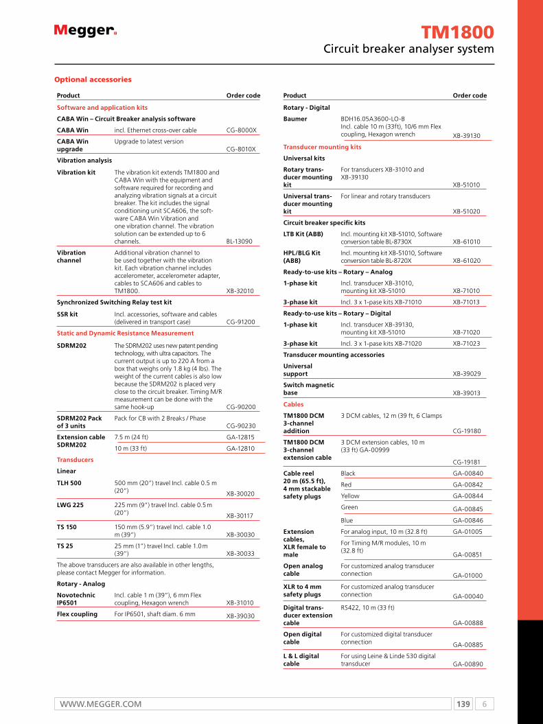
139 6WWW.mEggER.com
TM1800circuit breaker analyser system
Product Description Order code
Software and application kits
CABA Win – Circuit Breaker analysis software
CABA Win incl. Ethernet cross-over cable CG-8000X
CABA Win upgrade
Upgrade to latest versionCG-8010X
Vibration analysis
Vibration kit The vibration kit extends TM1800 and CABA Win with the equipment and software required for recording and analyzing vibration signals at a circuit breaker. The kit includes the signal conditioning unit SCA606, the soft-ware CABA Win Vibration and one vibration channel. The vibration solution can be extended up to 6 channels. BL-13090
Vibration channel
Additional vibration channel to be used together with the vibration kit. Each vibration channel includes accelerometer, accelerometer adapter, cables to SCA606 and cables to TM1800. XB-32010
Synchronized Switching relay test kit
SSr kit Incl. accessories, software and cables (delivered in transport case) CG-91200
Static and Dynamic resistance measurement
SDrm202 The SDRM202 uses new patent pending technology, with ultra capacitors. The current output is up to 220 A from a box that weighs only 1.8 kg (4 lbs). The weight of the current cables is also low because the SDRM202 is placed very close to the circuit breaker. Timing M/R measurement can be done with the same hook-up CG-90200
SDrm202 Pack of 3 units
Pack for CB with 2 Breaks / PhaseCG-90230
Extension cable SDrm202
7.5 m (24 ft) GA-12815
10 m (33 ft) GA-12810
Transducers
Linear
TLH 500 500 mm (20”) travel Incl. cable 0.5 m (20”) XB-30020
LWG 225 225 mm (9”) travel Incl. cable 0.5 m (20”) XB-30117
TS 150 150 mm (5.9”) travel Incl. cable 1.0 m (39”) XB-30030
TS 25 25 mm (1”) travel Incl. cable 1.0 m (39”) XB-30033
The above transducers are also available in other lengths, please contact Megger for information.
rotary - Analog
Novotechnic IP6501
Incl. cable 1 m (39”), 6 mm Flex coupling, Hexagon wrench XB-31010
flex coupling For IP6501, shaft diam. 6 mm XB-39030
Product Description Order code
rotary - Digital
Baumer BDH16.05A3600-LO-B Incl. cable 10 m (33ft), 10/6 mm Flex coupling, Hexagon wrench XB-39130
Transducer mounting kits
Universal kits
rotary trans-ducer mounting kit
For transducers XB-31010 and XB-39130
XB-51010
Universal trans-ducer mounting kit
For linear and rotary transducers
XB-51020
Circuit breaker specific kits
LTB Kit (ABB) Incl. mounting kit XB-51010, Software conversion table BL-8730X XB-61010
HPL/BLG Kit (ABB)
Incl. mounting kit XB-51010, Software conversion table BL-8720X XB-61020
ready-to-use kits – rotary – Analog
1-phase kit Incl. transducer XB-31010, mounting kit XB-51010 XB-71010
3-phase kit Incl. 3 x 1-pase kits XB-71010 XB-71013
ready-to-use kits – rotary – Digital
1-phase kit Incl. transducer XB-39130, mounting kit XB-51010 XB-71020
3-phase kit Incl. 3 x 1-pase kits XB-71020 XB-71023
Transducer mounting accessories
Universal support XB-39029
Switch magnetic base XB-39013
Cables
Tm1800 DCm 3-channel addition
3 DCM cables, 12 m (39 ft, 6 Clamps
CG-19180
Tm1800 DCm 3-channel extension cable
3 DCM extension cables, 10 m (33 ft) GA-00999
CG-19181
Cable reel 20 m (65.5 ft), 4 mm stackable safety plugs
Black GA-00840
Red GA-00842
Yellow GA-00844
Green GA-00845
Blue GA-00846
Extension cables, XLr female to male
For analog input, 10 m (32.8 ft) GA-01005
For Timing M/R modules, 10 m (32.8 ft)
GA-00851
Open analog cable
For customized analog transducer connection GA-01000
XLr to 4 mm safety plugs
For customized analog transducer connection GA-00040
Digital trans-ducer extension cable
RS422, 10 m (33 ft)
GA-00888
Open digital cable
For customized digital transducer connection GA-00885
L & L digital cable
For using Leine & Linde 530 digital transducer GA-00890
Optional accessories
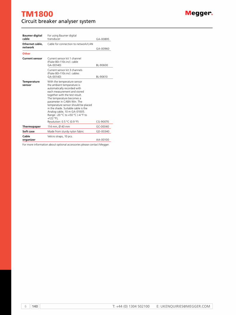
6 140 T: +44 (0) 1304 502100 E: [email protected]
Baumer digital cable
For using Baumer digital transducer GA-00895
Ethernet cable, network
Cable for connection to network/LAN
GA-00960
Other
Current sensor Current sensor kit 1 channel (Fluke 80i-110s incl. cable GA-00140) BL-90600
Current sensor kit 3 channels (Fluke 80i-110s incl. cables GA-00140) BL-90610
Temperature sensor
With the temperature sensor the ambient temperature is automatically recorded with each measurement and stored together with the test result. The temperature becomes a parameter in CABA Win. The temperature sensor should be placed in the shade. Suitable cable is the Analog cable, 10 m GA-01005. Range: -20 °C to +50 °C (-4 °F to +122 °F), Resolution: 0.5 °C (0.9 °F) CG-90070
Thermopaper 114 mm, Ø 40 mm GC-00040
Soft case Made from sturdy nylon fabric GD-00340
Cable organizer
Velcro straps, 10 pcs.AA-00100
For more information about optional accessories please contact Megger.
TM1800circuit breaker analyser system
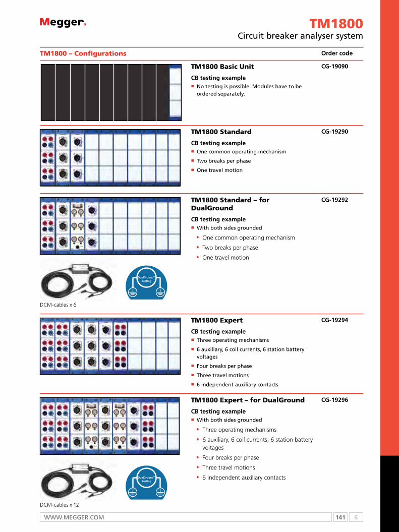
141 6WWW.mEggER.com
TM1800circuit breaker analyser system
TM1800 – Configurations Order code
TM1800 Basic Unit
CB testing example No testing is possible. modules have to be ordered separately.
CG-19090
TM1800 Standard
CB testing example one common operating mechanism
Two breaks per phase
one travel motion
CG-19290
DCM-cables x 6
TM1800 Standard – for DualGround
CB testing example With both sides grounded
One common operating mechanism Two breaks per phase One travel motion
CG-19292
TM1800 Expert
CB testing example Three operating mechanisms
6 auxiliary, 6 coil currents, 6 station battery voltages
Four breaks per phase
Three travel motions
6 independent auxiliary contacts
CG-19294
DCM-cables x 12
TM1800 Expert – for DualGround
CB testing example With both sides grounded
Three operating mechanisms 6 auxiliary, 6 coil currents, 6 station battery voltages
Four breaks per phase Three travel motions 6 independent auxiliary contacts
CG-19296

6 142 T: +44 (0) 1304 502100 E: [email protected]
Product Order code
Tm1800 – Separate items
Tm1800 Basic UnitComplete with: HDD module, CABA Local, Transport case, USB Memory
CG-19090
Control module (3 independent contacts)Including: 3 cable sets, 5 m (16 ft), GA-00877
CG-19030
Timing m/r module (6 channels + 6 PIR)Including: 3 cable sets, 5 m (16 ft) total length, 2 m (6.5 ft) spread, GA-00850
CG-19080
DCm moduleIncluding: 3 DCM-cables, 12 m (39 ft)
CG-19190
DCm moduleIncluding: 6 DCM-cables, 12 m (39 ft)
CG-19192
Analog module (3 channels)Including: 3 cable sets, 10 m (33 ft), GA-01005
CG-19000
Digital module (6 channels) CG-19040
Timing Aux module (6 channels)Including: 3 cable sets, 5 m (16 ft), GA-00870
CG-19060
Printer moduleIncluding: Paper spool, GC-00040
CG-19050
Optional accessories
CABA WinSee separate datasheet for CABA Win.
IPS-CBEXIPS CBEX is a database for circuit breakers and can be purchased as a stand alone software or as a server version and also as a attractively priced package together with TM1800 Expert.For more information please visit our web site or contact customer service.
Product Order code
Tm1800 – Configurations
Tm1800 Standard CG-19290
Including:CG-19090 TM1800 Basic Unit 1CG-19030 TM1800 Control Module 1CG-19080 TM1800 Timing M/R Module 1CG-19000 TM1800 Analog Module 1CG-8000X CABA Win - TM1800 1
Tm1800 Standard – for DualGround testing CG-19292
Including:CG-19090 TM1800 Basic Unit 1CG-19030 TM1800 Control Module 1CG-19080 TM1800 Timing M/R Module 1CG-19192 TM1800 DCM Module 1CG-19000 TM1800 Analog Module 1CG-8000X CABA Win - TM1800 1
Tm1800 Expert CG-19294
Including:CG-19090 TM1800 Basic Unit 1CG-19030 TM1800 Control Module 2CG-19080 TM1800 Timing M/R Module 2CG-19000 TM1800 Analog Module 1CG-19060 TM1800 Timing AUX Module 1CG-8000X CABA Win - TM1800 1
Tm1800 Expert – for DualGround testing CG-19296
Including:CG-19090 TM1800 Basic Unit 1CG-19030 TM1800 Control Module 2CG-19080 TM1800 Timing M/R Module 2CG-19192 TM1800 DCM Module 2CG-19000 TM1800 Analog Module 1CG-19060 TM1800 Timing AUX Module 1CG-8000X CABA Win - TM1800 1
OrDErING INfOrmATION
TM1800circuit breaker analyser system

143 6WWW.mEggER.com
SDrm202n Enables resistance measurement on circuit breakers
n Small and light weight
n A number of operations can be run with short waiting
intervals
DescriptionThe SDRM202 is an accessory for TM1800 and EGIL. EGIL must
be equipped with the SDRM option and CABA Win version
R03A or higher is needed.
The SDRM202 is intended to use for both static and dynamic
resistance measurements (SRM and DRM) on high voltage
circuit breakers or other low resistive devices. Used together
with TM1800 or EGIL the current and also the voltage-drop
across the circuit breaker contacts are measured. The measuring
unit can thus calculate the resistance as a function of time.
A system consists of an SDRM202 unit with current cables and
an SDRM Cable which comes in three versions; for TM1800
and EGIL respectively. The SDRM Cable is a small box with
integrated cables for connection to the SDRM202 and to
TM1800 or EGIL.
SDRM202Static / dynamic resistance measurement
Specifications SDRM202Inaccuracy is specified for 1 year after calibration at 22 °C to 28 °C, relative humidity 90%. Specifications are valid after 30 minutes warm up time. Specifications are subject to change without notice.
EnvironmentApplication field The instrument is intended for use
in high-voltage substations and industrial environments.
Installation category CAT I
Pollution degree 2
Temperature
Operating -20 °C to +50 °C (-4 °F to +122 °F)
Storage & transport -40 °C to +70 °C (-40 °F to +158 °F)
Vibration IEC 60068-2 - 6 2 g for 5 - 500 Hz
Shock (non-operating) IEC 60068-2-27 30 g, half-sine, 11 ms
Degree of protection
SDRM202 (Box) and SDRM Cable interconnected
IP 43
Humidity 5% – 95% RH, non-condensing
CE-markingLVD 2006/95/EC
EMC 2004/108/EC
GeneralPower inlet
VoltageCurrentDimensions
24 V / 2.5 A
24 V DC (max) 21 V DC (min)2.5 A (max 50% intermittence)160 x 240 x 90 mm (6.3”x 9.4”x 3.5”) excl. binding posts
Weight 1.8 kg (4 lbs) 4.3 kg (9.5 lbs) incl. current cables
Total incl. transport case with accessories
11 kg (24 lbs)
SDRM CableExtension cable
0.2m (0.7 ft), 0.7 kg (1.5 lbs)7.5 m (24.5 ft), 0.7 kg (1.5 lbs)
SDrm202 – TerminalsCUrrENT OUTPUT terminals 1 and 2Open circuit 2.5 V DC (max)
Short circuit current (max)
Instantaneous 500 A DC
After 2 seconds 150 A ±10%
Minimum current with cables
Instantaneous 200 A DC
After 1 second 140 A DC
Overvoltage protection 45 V between terminals and between terminals and ground
Not to be connected to circuits generating peak power pulse above 1500 W (10/1000 µs)
SPECIfICATIONS
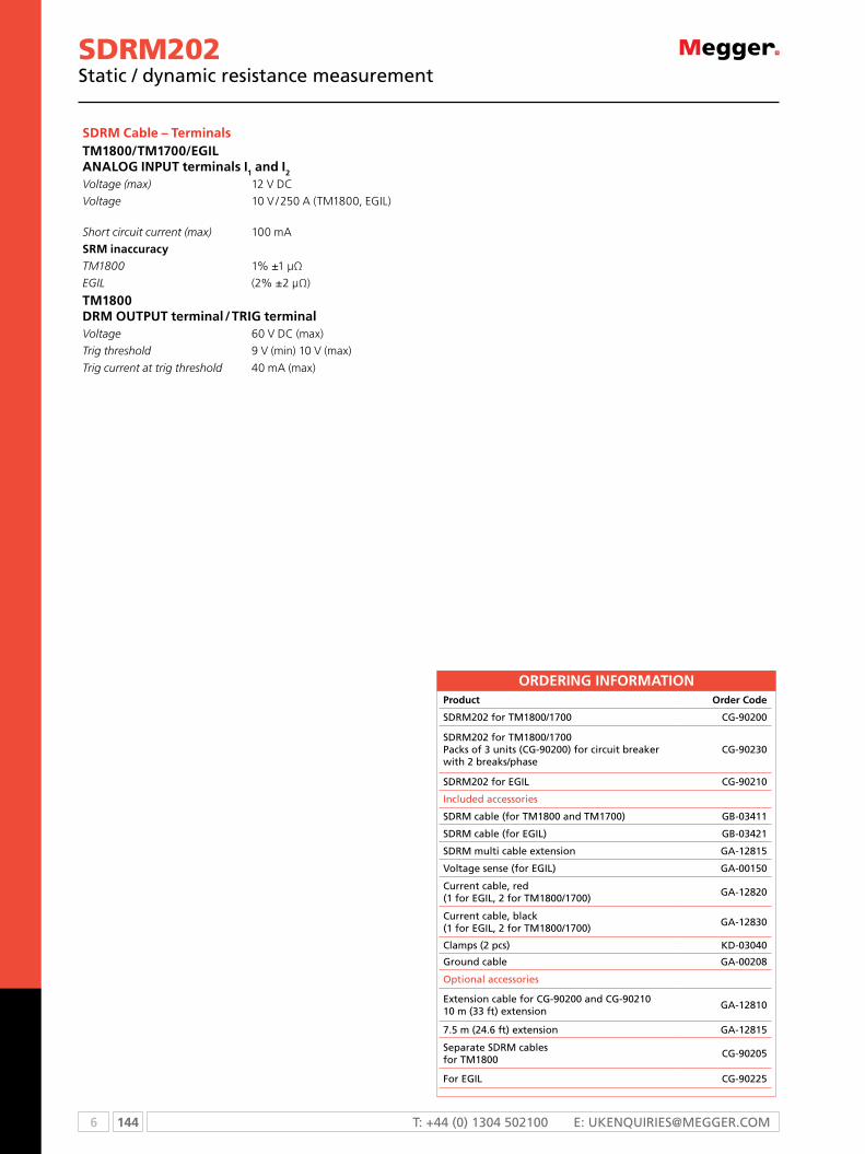
6 144 T: +44 (0) 1304 502100 E: [email protected]
SDrm Cable – TerminalsTm1800/Tm1700/EGIL ANALOG INPUT terminals I1 and I2
Voltage (max) 12 V DC
Voltage 10 V / 250 A (TM1800, EGIL)
Short circuit current (max) 100 mA
Srm inaccuracyTM1800 1% ±1 μΩ
EGIL (2% ±2 μΩ)
Tm1800 Drm OUTPUT terminal / TrIG terminalVoltage 60 V DC (max)
Trig threshold 9 V (min) 10 V (max)
Trig current at trig threshold 40 mA (max)
SDRM202Static / dynamic resistance measurement
OrDErING INfOrmATIONProduct Order Code
SDRm202 for Tm1800/1700 cg-90200
SDRm202 for Tm1800/1700 Packs of 3 units (cg-90200) for circuit breaker with 2 breaks/phase
cg-90230
SDRm202 for EgIL cg-90210
Included accessories
SDRm cable (for Tm1800 and Tm1700) gB-03411
SDRm cable (for EgIL) gB-03421
SDRm multi cable extension gA-12815
Voltage sense (for EgIL) gA-00150
current cable, red(1 for EgIL, 2 for Tm1800/1700)
gA-12820
current cable, black(1 for EgIL, 2 for Tm1800/1700)
gA-12830
clamps (2 pcs) KD-03040
ground cable gA-00208
optional accessories
Extension cable for cg-90200 and cg-90210 10 m (33 ft) extension
gA-12810
7.5 m (24.6 ft) extension gA-12815
Separate SDRm cablesfor Tm1800
cg-90205
For EgIL cg-90225

145 6WWW.mEggER.com
VIDARVacuum interrupter tester
VIDArn Enables resistance measurement on circuit breakers
n Small and light weight
n A number of operations can be run with short waiting
intervals
DescriptionWhen a vacuum circuit breaker is commissioned or undergoes
routine tests, it is very important to be able to ascertain
whether or not the Vacuum Interrupter (VI) is intact before
putting it back into operation.
VIDAR enables you to check the integrity of the vacuum
interrupter quickly and conveniently by means of the known
relationship between the flashover voltage and the vacuum
interrupter. A suitable test voltage (DC) is applied to the
breaker, and the result is known immediately.
VIDAR permits you to select among test voltages from 10 to
60 kV DC. One of these voltages is customized and specified
by the customer when ordering. A green lamp indicates
approval of the VI. A red lamp indicates that it is defective.
Two-hand control and a high-voltage warning lamps enhances
safety.
VIDAR has been developed in close collaboration with leading
manufacturers of vacuum circuit breakers. It weighs only
about 6 kg (15 lbs), and it is easy to use since interrupters do
not have to be dismounted for testing. VIDAR is therefore
ideal for use in the field or shop floor applications.
Applications
The VIDAR vacuum tester is used to test the ability of the VI in
a vacuum circuit to inhibit flashover. The rugged, lightweight,
compact and portable VIDAR is ideal for field work and shop
floor applications.
The VI in vacuum breakers does not last forever. Leakage
starts after years or decades and the interrupters fill with air
making the breaker unreliable. In most cases, the leakage
process is rapid once it has started. In addition to leakage, dirt
on the poles and on the exterior surface of the interrupter
can make it unsafe during operation. The mechanics of the
breaker can become misaligned so that the distance between
the poles is no longer adequate. VIDAR uses high voltage DC
to test the integrity of vacuum breakers.
Connection diagram for the VIDAr

6 146 T: +44 (0) 1304 502100 E: [email protected]
p ~10 mbarp
-2po
B
AUp
log p
log Ud
p Interrupter pressurepo Atmos. pressurePp max. pressure on pass-
ing voltage test
fig. 1: flashover threshold voltage plotted against pressure in vacuum interrupter.
Ud Breakdown voltageUp Test voltage
Flashover threshold voltage
The curve shown in Fig. 1 illustrates the relationship between
the VI’s internal pressure and its ability to inhibit flashover.
This relationship permits the vacuum to be checked indirectly
by measuring the voltage threshold. One special advantage of
this method is that you do not need to disassemble the circuit
breaker in order to test it.
The voltage is selected so that test point A is sufficiently far
from point B (when the chamber is filled with air). However,
the electric stress in the chamber must not be too high. In
normal situations, the pressure is less than 10-2 mbar.
For guidance on test voltage refer to IEC 694 and ANSI C37-06
standards
VIDARVacuum interrupter tester
Features and Benefits1. High voltage cable. For connection of the test voltage and
ground to the vacuum breaking chamber.
2. cANcEL lamp. Lights up when:
• the test interval has exceeded one minute.
• you try to conduct a one minute test less than two minutes after the latest test.
• the HIgH-VoLTAgE indicator malfunctions.
1 4 5
7987
3 62
3. HIgH-VoLTAgE warning lamp. Shows that the high voltage is applied.
4. Test voltage selector. 10 to 60 kV Dc. one of these voltages is customized and specified by the customer when ordering.
5. Protective earth (ground) terminal.
6. Large test clip connectors – provides for quicker connection and more efficient testing process
7. TEST Safety control knobs. Both knobs must be turned simultaneously to apply high voltage to the test object.
8. AccEPTABLE green lamp. Lights up when the breaking chamber test result is positive.
9. DEFEcTIVE red lamp. Lights up when the breaking chamber test result is negative, when the flashover threshold voltage is too low.

147 6WWW.mEggER.com
Specifications VIDARSpecifications are valid at nominal input voltage and an ambient temperature of +25 °C, (77 °F). Specifications are subject to change without notice.
EnvironmentApplication field The instrument is intended for use in
medium and high-voltage substations and industrial environments.
Temperature
Operating 0 °C to +50 °C (32 °F to +122 °F)
Storage & transport -40 °C to +70 °C (-40 °F to +158 °F)
Humidity 5% – 95% RH, non-condensing
CE-markingLVD 2006/95/EC
EMC 2004/108/EC
GeneralMains voltage 115 / 230 V AC (switchable), 50 / 60 Hz
Power consumption 69 VA (max)
Protection Overload cut-out
Dimensions
Instrument 250 x 210 x 125 mm (9.8” x 8.3” x 4.9”)
Transport case 460 x 430 x 210 mm (18.0” x 17” x 8.3”)
Weight 6.9 kg (15.5 lbs) 10.7 kg (23.6 lbs) with accessories and transport case
measurement sectionIndicatorsGreen lamp Indicates an approved breaking chamber
Red lamp Indicates a defect breaking chamber, lights up if the current exceeds 0.3 mA
Yellow lamp Indicate that the test was interrupted
OutputStandard voltages, switchable
10, 14, 25, 40 and 60 kV DC
Customized voltage Between 10 and 60 kV DC. Determined at the factory. Default voltage is 50 kV.
Ripple Max 3%
SPECIfICATIONS
OrDErING INfOrmATIONProduct Order code
VIDARIncluded accessories: Permanently mounted cable set 5 m (16 ft), ground cable and transport case (GD-00030) BR-29090
VIDARVacuum interrupter tester

6 148 T: +44 (0) 1304 502100 E: [email protected]
B10EAc/Dc voltage power supply
B10En Reliable and stable power supply for circuit breaker
testing
n Continuously variable 24-250 V AC or DC output
n Separate outputs for close coil, trip coil and spring
charging motor voltage
n Direct triggering for minimum trip voltage testing
n Operate with a breaker analyzer for efficiency in testing
sequence
DescriptionA variable DC voltage is needed to test a circuit breaker.
Substation batteries should not be used since this entails
considerable risk for testing personnel, testing equipment and
also for the equipment being tested. The best way to ascertain
whether or not solenoids and protective mechanisms are
sluggish or working properly is to perform a test at minimum
tripping voltage. The minimum trip voltage test is described
in international and national standards such as IEC 62271-100,
ANSI C37.09 etc.
B10E can be used to test breaker coils in this manner. It
provides a ripple-free variable DC voltage that can easily
accommodate a high, variable load.
Since there is a separate output for supplying spring-charging
motors, the B10E is ideal for testing circuit breakers where
auxiliary voltage is not connected or available.
The compact Power Supply Unit B10E provides reliable
assistance to those who do maintenance on high-voltage
breakers. The control panel’s intuitive layout makes it easy
to operate, and the built-in thermal cutout and overload
protector make it safe to use. The B10E has been developed
in collaboration with breaker manufacturers and testing
personnel.
Application
The B10E is a portable self contained test set designed
specifically for use in substations and industrial locations. The
B10E is intended for testing medium and high-voltage power
circuit breakers. Using the latest technology the B10E uses a
ripple free variable DC voltage to operate breaker coils, and
charging motors to ascertain the condition of these devices
with respect to the manufacturer’s original specifications.
Testing the minimum trip voltage of a breaker.
149 6WWW.mEggER.com
B10EAc/Dc voltage power supply
Specifications B10ESpecifications are valid at nominal input voltage and an ambient temperature of +25 °C, (77 °F). Specifications are subject to change without notice.
EnvironmentApplication field The instrument is intended for use in
medium and high-voltage substations and industrial environments.
Temperature
Operating 0 °C to +50 °C (32 °F to +122 °F)
Storage & transport -40 °C to +70 °C (-40 °F to +158 °F)
Humidity 5% – 95% RH, non-condensing
CE-markingEMC 2004/108/EC
LVD 2006/95/EC
GeneralMains voltage 115 / 230 (135 / 250) V AC, 50 / 60 Hz
Power consumption (max) 3300 W
Protection Thermal cut-outs, +80 °C (+176 °F) Short-circuit protectors at DC outputs
Dimensions
Instrument 350 x 270 x 220 mm (13.8” x 10.6” x 8.7”)
Transport case 610 x 290 x 360 mm (24.0” x 11.4” x 14.2”)
Weight 20.8 kg (45.8 lbs) 29.3 kg (64.6 lbs) with accessories and transport case
Test lead set, with 4 mm stackable safety plugs
2 x 0.25 m (0.8 ft), 2.5 mm² 2 x 0.5 m (1.6 ft), 2.5 mm² 8 x 2 m (6.6 ft), 2.5 mm²
Display LCD
measurement sectionVoltmeter – digital
Range 0 – 300 V DC, 0 – 300 V AC
Resolution 1 V
Inaccuracy ±1% of displayed value, DC ±2.5% of displayed value, AC
Current shunt 5 A / 50 mV ±0.5% (built-in)
SPECIfICATIONS Outputs (DC), CATIICOIL, CLOSING/BrEAKING
Output voltage 24-300 V DC
Load interval Max 1 s (at currents over 50 mA)
Ripple 2% peak-to-peak of the preset voltage
No-load voltage (V) Current (A) Load dependency24 10 <6 %
48 10 <3 %
110 7.9 <2 %
250 3 <2 %
300 1.25 <2 %
Outputs (AC), CATIICOIL, CLOSING/BrEAKINGOutput voltage 24-300 V AC
Load current Max 5 A
Load interval Max 30 min
Output DC, CATIImOTOrOutput voltage 24-300 V DC (loaded)
Open circuit voltage (V)
Current (A)
Load voltage (V)
max load interval (s)
44 18 24 20
48 12 40 60
48 18 30 20
120 12 90 60
120 18 70 20
240 6 200 60
240 9 185 20
max voltage: Terminals to protective earth (ground)Terminal Voltage
Coil closing, AC & DC 300 V AC
Coil breaking, AC & DC 300 V AC
Motor 250 V AC
Shunt 250 V AC
Trigger closing 250 V AC
Trigger breaking 250 V AC
OrDErING INfOrmATIONProduct Order code
B10EIncluded accessories: Cable set GA-00032 Transport case GD-00182 BG-29092

6 150 T: +44 (0) 1304 502100 E: [email protected]
MS-2An Light weight, portable primary injection test instrument
n Overcurrent relay testing
n Ground fault performance testing for NEC 230.95
n Circuit breaker testing
DescriptionThe MS-2A test set is used around the world by several
thousand utility companies, industrial plants and electrical
service organizations.
The MS-2A is a self-contained test set that incorporates a
variable high-current output and appropriate control circuitry
and instrumentation for testing thermal, magnetic or solid-
state motor overload relays, molded-case circuit breakers,
ground-fault trip devices and overcurrent relays.
The MS-2A is capable of testing the time-delay characteristics
of overcurrent relays, motor overload relays and molded-case
circuit breakers rated up to 125 amperes, when following the
recommended test procedure of testing the time delay of
these devices at three times their rating.
Higher currents are available for the short durations required
to test an instantaneous trip element. For example, the test
set will provide a maximum short-duration output of 750
amperes through a typical, 125 ampere, molded-case circuit
breaker.
MS-2ACircuit breaker and overcurrent relay test set
Input
Input Voltage (specify one) 120 V OR 240 V, 50/60 Hz, 1φ
Output
Output Ranges
The output is continuously adjustable in four ranges to accommodate a variety of test-circuit impedances:
0 to 5 A at 120 V max. 0 to 25 A at 24 V max. 0 to 120 A at 6 V max. 0 to 240 A at 3 V max.
Output Capacity
The output circuit is designed to permit short-duration overloads and the output ranges will provide several times their current rating, provided the output voltage is sufficient to push the desired current through the impedance of the test circuit. The test set is capable of testing the time-delay characteristics of devices rated up to 125 A using a test current of three times their rating (375 A). Additionally, to perform an instantaneous trip test, it will provide 750 A through a typical, 125 A, molded-case circuit breaker connected with the test leads provided with the test set.
Overload Capability
To increase use of the test set, it is designed so that the current ratings may be exceeded for short durations. Because the magnitude of the output current is determined by the impedance of the load circuit, the voltage rating must be sufficient to push the desired current through the device under test and the connecting test leads.
SPECIFICATIONS
Percent RatedCurrent
MaximumTime On
MinimumTime Off
100 (1x) 30 min 30 min
200 (2x) 3 min 8 min
300 (3x) 30 s 4 min
151 6WWW.mEggER.com
Specifications continued
Output Initiate Circuit
The test set uses a solid-state output initiating circuit. To increase reliability and eliminate contact maintenance, this circuit uses a triac instead of a contactor to initiate the output. The initiating circuit provides momentary and maintained modes to control output duration. The momentary mode is used whenever the output is to be on for a short duration, such as when performing instantaneous trip tests, or to avoid damage or overheating of the device under test while setting the test current. In the maintained mode, the output remains energized until manually turned off or, when performing timing tests, until the device under test operates — which both stops the timer and de-energizes the output.
INSTRuMENTATION
Ammeter
Operating Modes (switch-selected)
MemoryNormal
Display31/2 digit, extra-bright LED display with 0.3 in. (7.62mm) numerals
Ranges (switch-selected) 0 to 1.999/19.99/199.9/750 A
ContinousAccuracy (overall ammeter system)
±1% of reading, ±1 digit on three high ranges ±1% of range, ±1 digit on low range
Timer
Display5-digit, extra-bright, LED display with 7.62mm (0.3 in.) numerals
Ranges (switch-selected)0 to 99.999 s 0 to 999.99 s 0 to 99999 cycles
Accuracy ±0.005% of reading, ±1 digit
Timer Control Circuit
This circuit automatically starts the timer when the output is energized and automatically stops the timer and de-energizes the output when the device under test operates. This circuit accommodates the following test conditions by simple switch selection of the appropriate mode:
Current Actuated
Used to test a device that has no auxiliary contacts to monitor, such as a single-pole circuit breaker. The timer stops when the output current is interrupted.
Normally Closed
Used to test a device with normally closed contacts. The timer stops and the output is de-energized when the contacts open.
Normally Open
Used to test a device with normally open contacts. The timer stops and the output is de-energized when the contacts close.
Enclosure
The test set is housed in a high strength, molded, suitcase-type enclosure with carrying handle and removable cover. Storage space is provided for test leads.
Standards
CE markedEN 61326-2-1 EN 61010-1 EN 61010-031
Mechanical data
Dimensions25 H x 35 W x 28 D cm (9.9 H x 14 W x 11 D in.)
Weight 15 kg (33 lb)
ORDERING INFORMATIONProduct Order Code
Model MS-2A
115 volt input MS-2A-115
230 volt input MS-2A-230
Included accessories
Test lead, red, 200 cm [2] 620143
Test lead, black, 200 cm [2] 620144
Alligator clip, red [2] 684006
Alligator clip, black [2] 684007
Test and maintenance record cards
Green [50] 2239
Buff [50] 2238
No. 2 high-current leads, 0.6 m (2 ft) [2] 620155
Fuses
0.125 A, 250 V, MDL [5] 981
Instruction manual [1] 750026
MS-2ACircuit breaker and overcurrent relay test set

6 152 T: +44 (0) 1304 502100 E: [email protected]
OCR-8015 and OCR-9150Automatic oil circuit recloser test sets
OCR-8015 and OCR-9150n Preprogrammed test sequences for reclosers and
sectionalizers
n High-capacity outputs to test virtually all reclosers
n Accurate duplication of high-voltage test results
n Simple operation and precise test results
n Simplified adjustment of test current
DescriptionThe OCR-8015 and OCR-9150 automatic oil circuit recloser test
sets are self-contained mobile test sets specifically designed
to verify the proper operation of automatic circuit reclosers
under simulated overload and fault conditions. This ensures
reliable system protection and coordination. Microprocessor-
based control and instrumentation systems ensure simple
operation with precise test results. OCR-8015 and OCR-9150
provide a variable high-current output with an impedance
compensation network to stabilize the output current.
They include appropriate instrumentation and control circuitry
to efficiently, accurately and safely test virtually all single-
phase and three-phase direct-acting reclosers produced by
manufacturers such as Cooper Power Systems, Inc., McGraw-
Edison (Kyle, Line Material), Westinghouse, General Electric,
Kearney, and Lexington Switch and Controls.
ApplicationsThe automatic oil circuit recloser test sets not only test
reclosers incorporating either oil or vacuum interrupters, but
also easily test sectionalizers. Additionally, they can perform
primary injection (high-current) testing of electronically
controlled reclosers.
The following tests are performed on reclosers.
Minimum trip current: This test determines the minimum
operating (pickup) point. The minimum pickup test is
performed by increasing current flow through the operating
coil of the recloser until the recloser begins to operate.
The microprocessor in either unit will detect, measure and
display the test current at this point. This is the pickup and is
usually two times the current rating of the coil.
Time-current characteristics: This test determines the
operating characteristics of the recloser under simulated fault
conditions. The time-current characteristics and sequence
of events tests are performed by subjecting the recloser to
simulated overloads using a recommended test current of four
to six times the coil rating.
The current, trip time and reclose time for each operation, as
well as the total clearing time, are all automatically measured
by the test sets. OCR-9150 has the additional capability to test
the time-current characteristics by simulating overloads as
high as eight to ten times the continuous current rating.
Sequence of operation: The units verify the number and
sequence of operations to lockout.
Operating time: A digital timer measures the elapsed time of
each operation.
Reclosing time: A digital timer measures the reclosing interval
between each operation.
Total clearing time: A digital timer measures the total elapsed
time to lockout.
Similar tests can be performed on electronically controlled
reclosers using primary injection testing. Primary injection not
only tests the electronic control, but also checks the entire
system including the CTs, control cable, auxiliary solenoids or
wiring connections.
These test sets can also be used to perform a lockout test on
sectionalizers. The lockout test is automatically performed
by a special programmed test sequence that automatically
applies and removes activating current to the sectionalizer.
This simulates the upstream operation of a recloser; therefore,
the sectionalizer should go through its normal sequence
to lockout. The number of current pulses required to reach
lockout is compared to the sectionalizer nameplate data.
OCR-8015 and OCR-9150 can also be used for other high-
current applications such as ratioing current transformers,
performing heat runs or testing direct-acting circuit breakers.
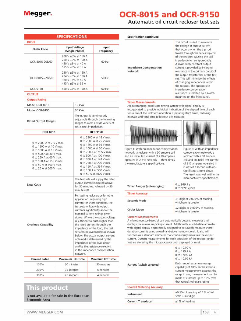
153 6WWW.mEggER.com
INPuT
Percent Rated Maximum On Time Minimum Off Time
100% 30 minutes 30 minutes
200% 75 seconds 6 minutes
300% 25 seconds 4 minutes
Order CodeInput Voltage (Single-Phase)
Input Frequency
OCR-8015-208/60
208 V ±5% at 150 A230 V ±5% at 150 A460 V ±5% at 40 A575 V ±5% at 35 A
60 Hz
OCR-8015-220/50
220 V ±5% at 150 A224 V ±5% at 150 A380 V ±5% at 40 A415 V ±5% at 35 A
50 Hz
OCR-9150 460 V ±5% at 150 A 60 Hz
OuTPuT
Output Rating
Model OCR-8015 15 kVA
Model OCR-9150 50 kVA
Rated Output Ranges
The output is continuously adjustable through the following ranges to meet a wide variety of test circuit impedances:
OCR-8015 OCR-9150
0 to 2000 A at 7.5 V max.0 to 1500 A at 10 V max.0 to 1000 A at 15 V max.0 to 500 A at 30 V max.0 to 250 A at 60 V max.0 to 100 A at 150 V max.0 to 50 A at 300 V max.0 to 25 A at 600 V max.
0 to 2800 A at 18 V max.0 to 2000 A at 25 V max.0 to 1400 A at 36 V max.0 to 1000 A at 50 V max.0 to 700 A at 71.5 V max.0 to 500 A at 100 V max.0 to 350 A at 143 V max.0 to 250 A at 200 V max.0 to 150 A at 334 V max.0 to 100 A at 500 V max.0 to 50 A at 1000 V max.
Duty Cycle
The test sets will supply the rated output current indicated above for 30 minutes, followed by 30 minutes off.
Overload Capability
For testing reclosers or for other applications requiring high current for short durations, the test sets will provide output currents significantly above the nominal current ratings given above. Where the output voltage is sufficient to push higher than the rated current through the impedance of the load, the test sets can be overloaded as shown below. The actual output current obtained is determined by the impedance of the load circuit and by the resistance selected in the impedance compensation network.
SPECIFICATIONS Specification continued
Impedance Compensation Network
This circuit is used to minimize the change in output current that occurs when the trip rod travels through the series trip coil of the recloser, causing the coil impedance to rise appreciably. A reasonably constant output current is provided by inserting resistance in the primary circuit of the output transformer of the test set. This will minimize the effects of changing impedances within the recloser. The appropriate impedance compensation resistance is selected by a switch mounted on the front panel.
Timer Measurements An autoranging, solid-state timing system with digital display is incorporated to provide individual indication of the elapsed time of each sequence of the recloser’s operation. Operating (trip) times, reclosing intervals and total time to lockout are indicated.
Figure 2: With an impedance compensation network, a recloser with a 50 ampere coil and an initial test current of 210 amperes operated in 0.783 of a second with no significant current decay. The result was well within the manufacturer’s specifications.
Figure 1: With no impedance compensation network, a recloser with a 50 ampere coil and an initial test current of 210 amperes operated in 2.641 seconds — three times the manufacturer’s specifications.
Timer Ranges (autoranging) 0 to 999.9 s 0 to 9999 cycles
Timer Accuracy
Seconds Mode±1 digit or 0.005% of reading, whichever is greater
Cycles Mode±2 digits or 0.005% of reading, whichever is greater
Current Measurements A microprocessor-based circuit automatically detects, measures and displays the minimum pickup current. Additionally, a solid-state ammeter with digital display is specifically designed to accurately measure short-duration currents using a read- and-store memory circuit. It also will function as a standard ammeter that continuously measures the output current. Current measurements for each operation of the recloser under test are stored by the microprocessor until displayed or reset.
Ranges (switch-selected)
0 to 19.99 A 0 to 199.9 A 0 to 1.999 kA 0 to 19.99 kA
Each range has an over-range capability of 10%. In the event a current measurement exceeds the range in use, measurement can be made of currents up to 10% over that range’s full-scale rating.
Overall Metering Accuracy
Instrument±0.5% of reading ±0.1% of full scale ± last digit
Current Transducer ±1% of reading
OCR-8015 and OCR-9150Automatic oil circuit recloser test sets
This product is not available for sale in the European Economic Area

6 154 T: +44 (0) 1304 502100 E: [email protected]
ORDERING INFORMATION
Product Order Code
OCR-8015
208 volt, 60-Hz input OCR-8015-208/60
220 volt, 50-Hz input OCR-8015-220/50
OCR-9150 OCR-9150
OCR-8015 with computer interface option
208 volt, 60-Hz input OCR8015-208/60C
220 volt, 50-Hz input OCR8015-220/50C
OCR-9150 with computer interface option
OCR-9150/C
Included accessories
Input cables, 4/0, 4.5 m (15 ft) [2] 17163
Output cables
Single 4/0 [1 pr] 1531
Double 4/0 [1 pr] 1532
Timer leads [1 pr] 2997
Optional accessories
RS232 and printer port conversion kit 12563
Protective cover, OCR-8015 only [1] PC-1
Panel indicators Panel lamps are incorporated for operator safety and convenience. They indicate numerous conditions such as input power on, output energized, excessive shots and excess time.
Accessory outlet A ground fault protected, 120 volt outlet with a capacity of 1.2 kVA is provided for convenient connection of accessory equipment.
Operator safety interlock system A safety interlock system, in conjunction with a foot switch, is incorporated to prevent the operator from leaving the control area of the test set. This helps to prevent accidental contact between the operator and the output section.
Output connections Busbar connections are provided for high-current ranges and insulated terminals are provided for high-voltage ranges.
Protection Appropriate protective devices are incorporated to protect the test sets from overloads and short circuits.
Enclosure For safety and mobility, each test set is housed in a single, rugged, sheet-metal enclosure with a low center of gravity, tow ring, lifting eyes and large locking swivel casters with brakes. To increase the maneuverability, all four casters swivel; however, they also can be easily locked into a fixed position when desired. Controls and instrumentation are positioned so the operator can simultaneously observe the recloser under test.
Dimensions
OCR-8015114 H x 135 W x 66 D cm (45 H x 53 W x 26 D in.)
OCR-9150114 H x 152 W x 71 D cm(45 H x 60 W x 28 D in.)
Weight
OCR-8015 495 kg (1100 lb)
OCR-9150 729 kg (1620 lb)
OCR-8015 and OCR-9150Automatic oil circuit recloser test sets
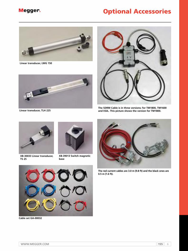
155 6WWW.mEggER.com
The red current cables are 3.0 m (9.8 ft) and the black ones are 0.5 m (1.6 ft).
The SDrm Cable is in three versions; for Tm1800, Tm1600 and EGIL. This picture shows the version for Tm1800.
Optional Accessories
Cable set GA-00032
XB-30033 Linear transducer, TS 25
Linear transducer, TLH 225
XB-39013 Switch magnetic base
Linear transducer, LWG 150

6 156 T: +44 (0) 1304 502100 E: [email protected]
rotary transducer, Novotechnic IP6501 (analog)
rotary transducer, Baumer BDH (digital)
SDrm Cable
Optional Accessories
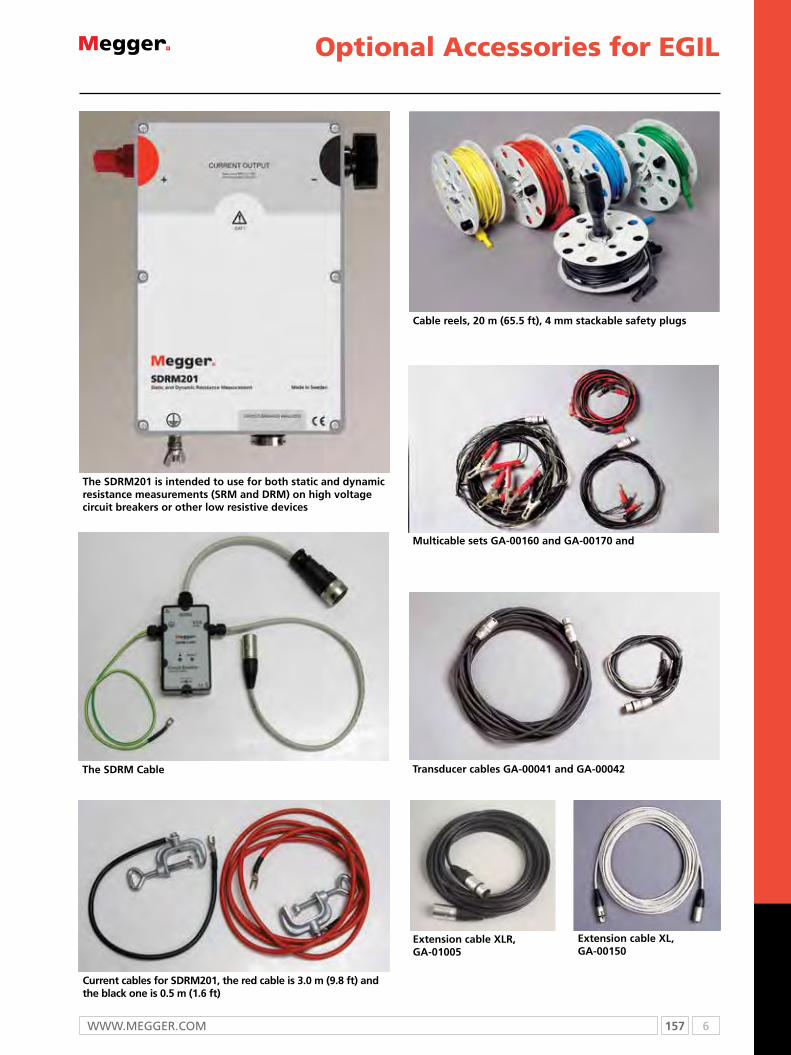
157 6WWW.mEggER.com
Optional Accessories for EGIL
Transducer cables GA-00041 and GA-00042
multicable sets GA-00160 and GA-00170 and
The SDrm Cable
Current cables for SDrm201, the red cable is 3.0 m (9.8 ft) and the black one is 0.5 m (1.6 ft)
Cable reels, 20 m (65.5 ft), 4 mm stackable safety plugs
The SDrm201 is intended to use for both static and dynamic resistance measurements (Srm and Drm) on high voltage circuit breakers or other low resistive devices
Extension cable XLr, GA-01005
Extension cable XL, GA-00150
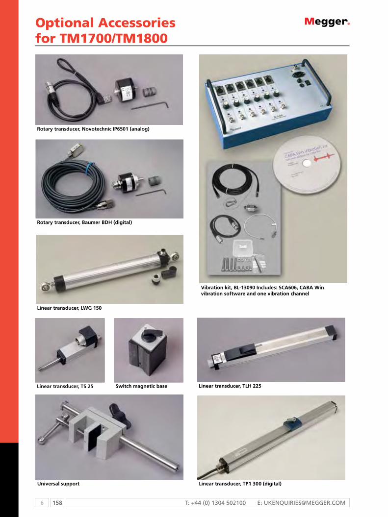
6 158 T: +44 (0) 1304 502100 E: [email protected]
rotary transducer, Novotechnic IP6501 (analog)
Linear transducer, LWG 150
Linear transducer, TS 25
rotary transducer, Baumer BDH (digital)
Linear transducer, TLH 225Switch magnetic base
Linear transducer, TP1 300 (digital)
Vibration kit, BL-13090 Includes: SCA606, CABA Win vibration software and one vibration channel
Universal support
Optional Accessoriesfor TM1700/TM1800

159 6WWW.mEggER.com
SDrm202
SDrm Cable
Extension cable XLr, GA-01005
Cable XLr, GA-00760
Cable reels, 20 m (65.5 ft), 4 mm stack- able safety plugs
rotary transducer mounting kit, XB-51010
LTc135, Load Tap changer power supply
Dcm1700, for timing using the Dualground™ method. Safe testing with both sides grounded.
Optional Accessoriesfor TM1700

7 160 T: +44 (0) 1304 502100 E: [email protected]
Selection guide ......................................................................................... 161Technical information ................................................................................ 162DET3TD 2 and 3 pole earth tester ............................................................. 164DET3TC ART enabled 3 pole tester ............................................................ 165DET4TC2 and DET4TCR2 2, 3 and 4 pole earth tester (stakeless) ............... 166 DET4TD2 and DET4TR2 2, 3 and 4 pole earth tester .................................. 167DET14C and DET24C earth resistance clamp testers .................................. 168DET2/2 auto earth tester ........................................................................... 169Ground testing methods chart .................................................................. 170Optional accessories .................................................................................. 171
Megger has more than 50 years experience of designing and building earth resistance testers. The latest generation is CATIV rated, and they have tough moulded cases.
Earth Resistance Testers
7

161 7WWW.mEggEr.com
SELECTION GUIDE
DET3TD DET3TC DET4TD2 DET4TR2 DET4TC2 DET4TCR2 DET14C DET24C DET2/2
Stakeless testing n n
Stakeless testing with optional test clamps n n
ART (Attached Rod Technique) with optional clamp n n n
Selectable test frequency n n n
Earth voltage range 0 to 100 V n n n n n n
2-wire testing n n n n n n
3-wire testing n n n n n n
4-wire testing n n n n n
Dry cell batteries n n n n n n
Recharging socket n n n
Rechargeable batteries n n n
Backlit display n n n n n
Digital display n n n n n n n n n
Test result storage/on screen reccall n n
Downloadable test results n
Earth current range 0.2 mA to 35 A n n
Earth current range 0.5 mA to 19.9 A (with optional measuring clamp) n n n
Resistance range
0.1 to 2 kΩ n n
0.1 to 20 kΩ n n
0.1 to 200 kΩ n n
0.05 to 1500 kΩ n n
0.010 to 19.99 kΩ n
PowerDB Lite included n n n n n

7 162 T: +44 (0) 1304 502100 E: [email protected]
Earth resistance testing is an essential procedure that underpins the
safety of electrical installations. Unfortunately it has a reputation
for being complicated, inconvenient and difficult to perform, with
difficulties in some circumstances of obtaining accurate results.
All of these issues are addressed by the latest range of earth
resistance testers from Megger, which has been extended to include
a model powered from rechargeable batteries and versions with
variable test frequency.
In addition, the maximum resistance that can be measured has been
increased ten fold for all models, and you can specify additional
options when purchasing test kits.
For demanding applications requiring maximum versatility, Megger
offers the DET4TC2 tester, which is powered from standard AA
batteries; and the DET4TCR2 tester, which uses rechargeable
batteries. The DET4TCR2 has an integral charger, and is supplied
complete with a mains adaptor.
These instruments support two-, three- and four-pole testing, as
well as Attached Rod Technique (ART), stakeless, leakage current
and earth noise voltage measurement. They also let you select the
test frequency from one of four options –
94 Hz, 105 Hz, 111 Hz and 128 Hz – making it easy, even in difficult
situations, to choose a frequency which minimises the effects of
interference.
Also available are the new DET4TD2 and DET4TR2 testers, the
former being designed for use with replaceable batteries, the latter
with rechargeable cells. Fully supporting the most popular earth
resistance test methods – two-, three- and four-pole testing – these
very competitively priced instruments are an ideal choice for use
where the exceptional versatility of the DET4TC2 models is not
needed.
Megger’s new earth resistance testers are offered in a wide range of
kit options. Basic kits include the instrument, a tough, hard carrying
case, a stake and wire kit (15 m, 10 m, 10 m and 3 m lengths) and
for rechargeable models, a mains unit. Adaptor kits replace the
stake and wire kit with right-angle terminal adaptors to connect
bare wires to terminals. Also offered for the DET4TC2 models are
kits for ART and stakeless testing.
All accessories are available separately which means that users can if
they wish, select the most appropriate combination to suit their own
particular needs rather than opting for a pre-configured kit.
Getting down to earth
Ask for your copy of ‘Getting Down To Earth’, an 80 page comprehensive guide to earth resistance testing. email [email protected]

163 7WWW.mEggEr.com
The complete range of earth testers
4 terminal testing for soil resistivity testingTesting soil resistivity is a fundamental part of earth system design,
providing the raw data on which the design is based. Factors
affecting soil resistivity include soil composition, temperature
and moisture content, which can vary with the seasons. Periodic
checking of the soil is necessary to ensure that seasonal variations
are within the design parameters of the system. The DET4TD2
features 4 pole testing for soil resistivity and includes a kit of four
stakes and wires.
3 terminal testing ground electrode testingThe classic methods of testing earth electrode resistance based
on fall of potential are used both at installation time and also for
periodic checking the condition of the electrodes. Unfortunately
soils that have low resistivity are often corrosive to electrodes,
making regular checking important. All the new family of Megger
earth testers allow you to perform this test and include stake and
wire kits as standard.
Attached rod technique (ART)Testing earth electrodes in existing installations using standard
three pole methods normally involves the disconnection of the
electrode under test to avoid the influence of parallel paths. These
parallel paths are created by the earthing system of the installation
or by other ground electrodes forming the ground system. Using
the Megger DET3TC ground tester with the ICLAMP allows you to
measure the individual earth electrode resistance, using traditional
fall of potential methods, but without disconnection of the electrode
under test.
2 terminal ground electrode testingUse where the resistance between a conducting part, such as
building steelwork and the ground electrode needs to be measured,
or where site conditions means that test stakes are impractical.
This test is performed using the same a.c. source as the 3 pole test
method and as such may not be suitable for bonding checks as
specified by local regulations. All of the new Megger earth testers
can perform this test and no external linking on the instrument is
required.
Stakeless measurement or clamp ground electrode testingThis technique is suitable for connected ground electrodes and
lightning systems as it relies on an existing complete circuit with
the soil to take its measurement. No disconnection is required; the
DET14C or DET24C is simply placed around the conductor where
it generates the signal in the circuit using magnetic induction and
then calculates the resistance. They have the added benefit of being
able to measure earth current. Care is needed in the application of
these instruments to ensure that the circuit under test is valid.
High resolution earth testingA high resolution to 1 mA is required to measure resistivity
to adequate depth on many substation and communication
sites. Measurement of the low earth values required on many
installations, to meet Ground Potential Rise (GPR) requirements need
this resolution to ensure valid results. Superior noise filtering greater
than 40 V peak to peak retains measurement resolution under real
test conditions.

7 164 T: +44 (0) 1304 502100 E: [email protected]
Spike check
c spike check Automatic
P spike check Automatic
Noise
noise check Automatic
noise rejection 40 V peak to peak
Wire test
2-wire test Yes
3-wire test Yes
Resistance
resistance accuracy 2% ±3 digits
resistance range 0.01 to 2000 Ω
Maximum probe resistance
rp limit 100 kΩ (50 V output voltage)
rc limit 100 kΩ (50 V output voltage)
Limits reduced to 50 kΩ for 25 V output voltage
Limits reduced to 5 kΩ for 0.01 Ω resolution on 18 Ω range
Voltage, frequency and current
Earth voltage accuracy 2% ±2 V
Earth voltage range 0 - 100 V a.c.
Test voltage 25 V or 50 V, user selectable (factory setting 50 V)
Test frequency 128 Hz
Test current 450 μA or 4.5 mA
Display
LcD
Power supply
Battery type 8 off AA cells
Battery life 3 hours or 700 consecutive tests
Temperature range
operating temperature range -15 ºC to +55 °C
storage temperature range -40 ºC to +70 °C
Environment
ingress protection IP54
Safety
IEC61010-1 CAT IV 100 V
EN61557-1, EN61557-5
EMC
IEC61326-1
Mechanical data
Dimensions (H x W x D) 203 mm x 148 mm x 78 mm
Weight 1 kg
SPECIFICATIONS
Product Order Code
Digital tester 2 and 3 terminal DET3TD
included accessories
Hard carry case
stake and wire kit
optional accessories
right angled terminal adaptor set 6220-803
2 replacement earth test spikes (200 mm, 80 mm dia.)
6220-804
3 replacement test leads (15 m, 10 m, 3 m) 6220-805
‘getting down to earth’ A megger guide to earth testing
21500-072
Black crocodile clip 6220-850
DET3TD2 and 3 pole earth tester
ORDERING INFORMATION
DET3TDn 2 and 3 pole testing
n selectable 25 V or 50 V output
n complete with lead and stake kit
n simple one button operation
n iP54 case plus hardwearing carry case
n Delivered with calibration certificate
DescriptionElectrical contractors choose DET3TD because it is simple
to use and robust. capable of performing 2 and 3 pole
measurements, this instrument is ideal for testing both
installation and lightning protection ground electrode
systems.
The instrument is tough in every way, built to work in the
toughest of outside conditions, and built to give you a high
level of electrical safety. This is demonstrated by specifications
such as iP54 ingress protection, high noise immunity, and
cAT iV safety.

165 7WWW.mEggEr.com
ORDERING INFORMATION
DET3TCArT enabled 3 pole earth tester
DET3TCn 2 and 3 pole testing
n selectable 25 V or 50 V output
n complete with lead and stake kit
n simple one button operation
n iP54 case plus hardwearing carry case
n Delivered with calibration certificate
DescriptionElectrical contractors choose DET3Tc because of its simplicity
and robustness. capable of performing 2 and 3 pole
measurements, this instrument is ideal for testing both
installation and lightning protection ground electrode
systems. The DET3Tc, with the addition of an icLAmP adds
the capability of performing ArT (Attached rod Technique)
measurements, removing the need to disconnect a single
electrode from a system to measure it.
Product Order Code
Digital tester 2 and 3 terminal DET3Tc
included accessories
Hard carry case
stake and wire kit
optional accessories
current measuring clamp icLAmP
right angled terminal adaptor set 6220-803
2 replacement earth test spikes (200 mm, 8 mm dia.)
6220-804
3 replacement test leads (15 m, 10 m, 3 m) 6220-805
‘getting down to earth’ A megger guide to earth testing
21500-072
Black crocodile clip (1) 6220-850
Spike check
c spike check Automatic
P spike check Automatic
Noise
noise check Automatic
noise rejection 40 V peak to peak
Wire test
2-wire test Yes
3-wire test Yes
no disconnect testing (ArT) Yes, with optional ICLAMP
Earth current
Earth current range with icLAmP 0.5 mA to 19.9 A
Earth current accuracy 5% ±3 digits
Resistance
resistance range 0.01 to 2000 Ω
resistance accuracy 2% ±3 digits
Maximum probe resistance
rp limit 100 kΩ (50 V output voltage)
rc limit 100 kΩ (50 V output voltage)
Limits reduced to 50 kΩ for 25 V output voltage
Limits reduced to 5 kΩ for 0.01 Ω resolution on 18 Ω range
Voltage
Earth voltage range 0 - 100 V a.c.
Earth voltage accuracy 2% ±2 V
Display
LCD
Power supply
Battery type 8 x AA cells
Temperature range
operating temperature range -15 ºC to +55 °C
storage temperature range -40 ºC to +70 °C
Environment
ingress protection IP54
Safety
iEc61010-1 cAT iV 100 V
En61557-1, En61557-5
EMC
iEc61326-1
Mechanical data
Dimensions (H x W x D) 203 mm x 148 mm x 78 mm
Weight 1 kg
SPECIFICATIONS

7 166 T: +44 (0) 1304 502100 E: [email protected]
DET4TC2 and DET4TCR22, 3 and 4 pole earth testers (ArT and stakeless)
Noise
c stake, P stake and noise check Automatic
noise rejection 40 V peak to peak
Testing
2-wire, 3-wire, 4-wire test Yes, no shorting links required
no disconnect testing (ArT) Yes, with ICLAMP
stakeless measurement Yes, with ICLAMP and VCLAMP
Instrument output
Voltage ±25 V or ±50 V at 94 Hz, 105 Hz, 111 Hz and 128 Hz
current 4.5 mA or 0.45 mA or 0.045 mA
Earth current range with clamp 0.5 mA to 19.9 A
Earth current accuracy 5% ±3 digits
Earth voltage range 0 to 100 V a.c.
Earth voltage accuracy 2% ±2 V
Resistance
resistance range 0.01 Ω to 200 kΩ
resistance accuracy 2% ±3 digits
ArT measurements 5% ±3 digits
stakeless measurements 7% ±3 digits
Maximum probe resistance:
rp limit 200 kΩ (50 V output voltage)
rc limit 200 kΩ (50 V output voltage)
Limits reduced to 100 kΩ for 25 V output voltage
Limits reduced to 5 kΩ for 0.01 Ω resolution
Power supply
Battery type:
DET4Tc2 8 AA (LR6) cells
DET4Tcr2 8 AA (LR6) NiMH rechargeable cells
Temperature range
storage temperature range -40 °C to +70 °C
operating temperature range -15 °C to +55 °C
Environment
ingress protection IP54
Safety
Complies with the requirements of IEC61010-1 100 V CAT IV between terminal pairs
Emc iEc61326-1
Mechanical data
Dimensions (H x W x D) 203 mm x 148 mm x 78 mm
Weight 1 kg
SPECIFICATIONS
ORDERING INFORMATION
Product and order code n feature £ optionDET4TC2
1000-345
DET4TCR2
1000-346
DET4TC2 + CLAMPS 1000-365
DET4TCR2 + CLAMPS 1000-366
DET4TC2 + KIT
1000-404
DET4TCR2 + KIT
1000-405
Hard carry case n n n n n n
stake and wire kit (15 m, 10 m, 10 m, 3 m) n n n n n n
right angle terminal adaptors (to connect bare wires to terminals) n n n n n n
External Ac/Dc charger n n n
icLAmP (for ArT testing) £ £ n n n n
VcLAmP (adds stakeless testing) £ £ n n n n
Field calibration check for instrument and cLAmPs £ £ n n n n
separate professional earth testing kit (2 x 50 m, 2 x 30 m, 4 auger stakes, tape measure, in hard carry case) £ £ £ £ n n
PowerDB Lite software n n n n n n
DET4TC2 and DET4TCR2n 2, 3 and 4 pole testing
n stakeless measurements
n user selectable test frequency
n Dry cell or rechargeable battery versions
n user selectable output voltage
n simple one button operation
DescriptionThe DET4Tc2 and its rechargeable counterpart the DET4Tcr2
are advanced ground testers offering advanced features to
contractors and utilities alike. capable of performing 2, 3, and
4 pole measurements, these instruments are ideal for testing
both ground electrode systems, and soil resistivity.
offering all the advantages of the DET4TD2 and DET4Tr2,
benefits are further enhanced with the addition of an icLAmP
and VcLAmP. The icLAmP will allow the user to perform ArT
(Attached rod Technique) measurements, removing the need
to disconnect a single electrode from a system to be able to
measure it. using both an icLAmP and a VcLAmP will add
the capability to perform stake-less measurements, just like
a clamp-on ground tester, ideal for locations where driving
auxiliary stakes is not practical. DE4Tc2 also includes variable
test frequency allowing you to move away from problem
noise frequencies, and it has extended resistance ranges
which extends soil resistivity capabilities.
167 7WWW.mEggEr.com
ORDERING INFORMATION
DET4TD2 and DET4TR22, 3 and 4 pole earth testers
Product Order Code
DET4TD2 1000-347
DET4Tr2 (rechargeable) 1000-324
included accessories
Hard carry case
stake and wire kit (15 m, 10 m, 3 m)
right angle terminal adaptors (to connect bare wires to terminals)
External Ac/Dc charger (rechargeable version only)
PowerDB Lite software
optional accessories
replacement hard carry case 5410-429
replacement earth test stakes (x2) (for included kit 200 mm, 8 mm dia.)
6220-804
Product Order Code
replacement earth test leads (x4) for included kit (15 m, 10 m, 10 m, 3 m)
6220-806
replacement external Ac/Dc charger (DET4Tr2 only)
6280-370
calibration check box (25 Ω) 1000-435
right angle terminal adaptor set 6220-803
Black crocodile clip (1) 6220-850
Professional earth testing kit (2 x 50 m, 2 x 30 m, 4 auger stakes, tape measure, in hard carry case)
6320-245
Vehicle 12 V socket charger (rechargeable versions only)
6280-375
‘getting down to earth’ A megger guide to earth testing
21500-072
DET4TD2 and DET4TR2n 2, 3 and 4 pole testing
n selectable 25 V or 50 V output
n Dry cell or rechargeable battery versions
n simple one button operation
n robust carry case
n Delivered with calibration certificate
DescriptionThe DET4TD2 and its rechargeable counterpart the DET4Tr2
are a popular choice with contractors due to their simplicity
and robustness. capable of performing 2, 3, and 4 pole
measurements these instruments are ideal for testing both
ground electrode systems, and soil resistivity.
These instruments are built to work in the toughest of outside
conditions, and engineered to give the user a high level of
electrical safety. This is demonstrated by specifications such
as iP54 ingress protection, high noise immunity, and cAT iV
safety.
Noise
c spike, P stake and noise check Automatic
noise rejection 40 V peak to peak
Wire test
2-wire, 3-wire test, 4-wire test Yes, no shorting links required
Instrument output
Voltage ± 25 V or ± 50 V at 128 Hz
current 4.5 mA or 0.45 mA
Resistance
resistance range 0.01 Ω to 20 kΩ
Earth voltage range 0 - 100 V
resistance accuracy 2% ± 3 digits
Maximum probe resistance:
rp limit 100 kΩ (50 V output voltage)
rc limit 100 kΩ (50 V output voltage)
Limits reduced to 50 kΩ for 25 V output voltage
Limits reduced to 5 kΩ for 0.01 Ω resolution
Earth voltage
Earth voltage range 0 to 100 V a.c.
Earth voltage accuracy 2 % ± 2 V
Display
31⁄2 digit high contrast liquid crystal
Power supply
Battery type:
DET4TD2 8 AA (LR6) cells
DET4Tr2 8 AA (LR6) NiMH rechargeable cells
Temperature range
operating temperature range -15 ºC to +55 ºC
storage temperature range -40 ºC to +70 ºC
Environment
ingress protection IP54
Safety
Complies with the requirements of IEC61010-1 100 V CAT IV between terminal pairs
Mechanical data
Dimensions (H x W x D) 203 mm x 148 mm x 78 mm
Weight 1 kg
SPECIFICATIONS

7 168 T: +44 (0) 1304 502100 E: [email protected]
DET14C and DET24Cn Elliptical clamp shape improves access to earth cables
and straps up to 50 mm
n Low maintenance flat jaw interface
n measures ground resistance from 0.05 Ω to 1500 Ω
n measures true rms ground leakage current from
0.02 mA rms to 35 A rms
n cAT iV 600 V safety rating
n Backlit LcD display
DescriptionThe DET14c and DET24c represent a new generation of
earth/ground clamp-on resistance testers. These instruments
induce a test current into earth systems and measure ground
resistance in multi ground installations without needing to
disconnect the ground. They offer better access through
elliptical jaw design and short body length to reach into
connection wells, with advanced features, simple operation
and cAT iV 600 V safety rating.
Designed with flat core ends they prevent dirt build up,
ensuring measurement integrity and improved reliability.
General
conductor size50 mm tapes, 39 mm Ø approximately
Battery type 4 x 1.5 V IEC LR6/AA alkaline
Display type4 digit and 6 digit alpha-numeric with backlight
range selection Automatic with each mode
Data loggingDET14C 256 recordsDET24C 2048 records
Data downloading (DET24c only) Opto-coupled IrDA-USB interface
Battery life24 hours (25 Ω lead) continuous testing (whilst measuring resistance)
sampling time <1 second
Temperature and humidity
Temperature range:
operating temperature -20 ºC to 55 ºC
storage temperature -40 ºC to 60 ºC
Humidity:
operating humidity Less than 85% RH
storage humidity Less than 75% RH
Environment
ingress protection IP40 with jaws closed
Safety
iEc 61010-2-032
cAT iV 600 V
EMC
class B compliant, iEc 61326, BsEn 61326
Mechanical data
Dimensions (H x W x D) 228 mm x 114 mm x 49 mm
Weight 985 g
SPECIFICATIONS
ORDERING INFORMATIONProduct Order Code
DET14c Digital earth test clamp-on meter 1000-761
DET24c Digital earth test clamp-on meter 1000-762
included accessories (DET14c and DET24c)
carry case 1001-715
carrying strap (wrist loop) 1001-716
user guide cD-rom 1001-198
calibration check 1001-498
Battery AA (alkaline) (4 required) 25511-841
included accessories (DET24c)
usB irDA dongle 90001-434
PowerDB Lite software 1000-576
DET14C and DET24CEarth resistance clamp testers
Ground resistancerange
Resolution Instrinsic certainty
0.05 - 0.99 Ω 0.01 Ω ±1.5% 0.05 Ω
1.00 - 9.999 Ω 0.01 Ω ±1.5% ±0.1 Ω
10.0 - 99.99 Ω 0.1 Ω ±2.0% ±0.5 Ω
100.0 - 199.9 Ω 0.1 Ω ±5.0% ±1 Ω
200 - 400 Ω 1 Ω ±10.0% ±5 Ω
400 - 600 Ω 1 Ω ±10% ±10 Ω
600 - 1200 Ω 10 Ω ±20%
1200 - 1500 Ω 10 Ω ±35%
Current range Resolution Instrinsic certainty
0.20 – 0.99 mA 0.01 mA ±2.0% ±0.05 mA
1.00 – 9.99 mA 0.01 mA ±2.0% ±0.05 mA
10.0 – 99.9 mA 0.1 mA ±2.0% ±0.1 mA
100 – 999 mA 1 mA ±2.0% ±1 mA
1.00 – 9.99 A 0.01 A ±2.0% ±0.01 A
10.0 A - 35 A 0.1 A ±2% ±0.1 A
Resistance measurement
Current measurement (RMS)

169 7WWW.mEggEr.com
ORDERING INFORMATION
DET2/2Auto earth tester
Product Order Code
Auto earth tester DET2/2
included accessories
mains supply lead for battery charging
operating instruction book 6171-728
Product Order Code
optional accessories
Earth testing kit 6310-755
comprising carrying case and pouch containing: Four galvanised steel spikes (‘L’ shape) 10 mm dia. x 350 mm long 30 m of cable on a winder 50 m of cable on a winder Two 3 m leads complete with connectors and clips Hammer
reel of cable, 50 m 6121-119
Resistance
Earth resistance range 0,010 Ω to 19,99 kΩ (auto-ranging), 1 mΩ resolution
Accuracy (23 °C ±2 °C) ±0,5% of reading±2 digits
service error ±5% of reading ±2 digits ±10 mΩ (meets VDE service error over 50 mΩ)
Test
Test frequency
105 to 160 Hz reversing d.c. (50 Hz operation default to 128 Hz, 60 Hz operation default to 150 Hz) Set in steps of 0,5 Hz
Test current 50 mA max (selectable high and low levels)
maximum output voltage < 50 V r.m.s.
maximum interference Typically 40 V peak-to-peak (50/60 Hz, sinusoidal nature)
Display
Alphanumeric LCD (130 mm x 35 mm) giving test information and a large (20 mm) 31⁄2-digit reading)
Temperature and humidity
Temperature coefficient < ±0.1% per °C over the temperature range -10 ºC to +40 °C
Temperature range:
operating -10 ºC to +40 °C
storage -20 ºC to +60 °C
Humidity:
operating 90% RH max. at 40 °C
Environment
ingress protection IP54
Flash test 3 kV a.c.
Voltage withstand In the event of a system fault, the instrument will withstand 240 V a.c. applied between any two terminals
Power supply
Internal
Rechargeable, sealed lead-acid battery
12 V (nominal), 2,6-Ah capacity
Battery voltage over which basic accuracy is maintained is 11,0 to 13,5 V
Battery life Approximately 5 hours continuous use
SPECIFICATIONS
DET2/2n High resolution 1 mΩ is ideal for large ground systems
n High accuracy for earth electrode and soil resistivity testing
n Test voltage 50 V max. for safety
n rechargeable battery power with long battery life and rapid re-charge
n A robust, versatile instrument with iP54 protection
n Filter and high current features to enable valid earth testing in difficult situations
DescriptionThe DET2/2 is the instrument of choice for those performing
measurements on larger, more complex grounding systems
including communications grounding systems and power
utility testing environments. The instrument is suitable for
soil resistivity measurements, which are used to establish the
optimum ground system location and design.
The instrument provides 1 mΩ resolution down to 10 mΩ,
ideal for the largest of ground systems, whilst the adjustable
test frequency, test current level and filtering may allow
adverse conditions influencing the test to be overcome.

7 170 T: +44 (0) 1304 502100 E: [email protected]
*Method Best Applications Advantages Limitations
Fall of PotentialSmall electrode systems (1 or 2 rods/plates); complex systems if full resistance curve is plotted
Extremely reliable; conforms to IEEE 81; operator has complete control of test set-up
Requires long distances (and long test leads) to the test probes on medium and large systems, time consuming and labour intensive
Simplified Fall of Potential Small and medium electrode systemsEasier to carry out than full Fall of Potential; much faster
Ineffective if the electrical centre is unknown, less accurate than full Fall of Potential method as fewer measurements are being made
61.8% Rule Small and medium electrode systemsSimplest to carry out; minimal calculation, fewest number of test probe moves
Assumes perfect conditions; ineffective if electrical centre is unknown; soil must be homogeneous; less accurate
SlopeLarge earth ground systems such as substations
Knowledge of electrical centre not necessary; long distances to test probes not necessary
Susceptible to non-homogeneous soil; less accurate, requires maths
Intersecting CurvesLarge earth ground systems such as substations
Knowledge of electrical centre not necessary, long distances to test probes not necessary
Numerous calculations and drawing of curves
Dead Earth (Two Point) Not recommended Quick and simple to performProblems of possible resistance overlap; non-metallic (high resistance) return
Star Delta
Ground systems located in congested urban areas and/or rocky terrain where probe positioning is difficult
Long distances for test probe positioning not necessary
Resistance areas should not overlap a number of calculations required
Four PotentialMedium to large earth ground systems
Knowledge of electrical centre not necessary
Long distances to test probes is still required, a number of calculations required
Clamp-OnSimple earth ground system with existing return path through multiple grounds
Quick, easy; includes bonding and overall connection resistance
Effective only in situations with multiple grounds in parallel; susceptible to noise; no basis in standards; no built-in proof
PowerDB Lite is included with all Megger DET4 range, DET14C and DET24C. PowerDB includes test forms for all of the above methods and performs all the calculations automatically.
GROUND TESTING METHODS CHART
*The Attached rod Technique (ArT) is based on Fall of Potential
Do you need...more information on earth testing? Ask for your copy of ‘getting Down to Earth’, megger’s technical guide to ground/earth testing. email [email protected]

171 7WWW.mEggEr.com
6310-755Earth testing kit
For use with DET2/2
6121-11950 m reel of cable
For use with DET2/2
Optional accessories
icLAmPCurrent measuring clamp
For use with DET4Tc2, DET4Tcr2
VcLAmP
For use with DET4Tc2, DET4Tcr2
6280-370Replacement external AC/DC charger
For use with DET4Tr2
6220-850Black crocodile clip
For use with DET3TD, DET3Tc, DET4TD2, DET4Tr2,
6220-824
Calibration check box (25 Ω)
For use with DET4Tc2, DET4Tcr2
6280-375Vehicle 12 V socket charger (rechargeable versions only)
For use with DET4Tcr2, DET4Tr2
6220-806Replacement earth test leads (x4) for included kit (15 m, 10 m, 3 m)
For use with DET4TD2, DET4Tr2
6220-804Replacement earth test stakes (x2) for included kit 200 mm, 8 mm dia
For use with DET3TD, DET3Tc, DET4TD2, DET4Tr2,
6220-803Right angle terminal adaptor set
For use with DET3TD, DET3Tc, DET4Tc2, DET4Tcr2, DET4TD2, DET4Tr2
5410-429Replacement hard carrying case
For use with DET4Tc2, DET4Tcr2, DET4TD2, DET4Tr2
6220-8053 replacement test leads (15 m, 10 m, 3 m)
For use with DET3TD, DET3Tc, DET4TD2, DET4Tr2,
6320-245Professional earth testing kit
For use with DET4TD2, DET4Tr2,DET4TD2, DET4Tr2
21500-072Getting Down To EarthA Megger guide to earth testing
For use with all earth testers

8 172 T: +44 (0) 1304 502100 E: [email protected]
Selection guide ......................................................................................... 173Technical information ................................................................................ 174INGVAR primary current injection test system ............................................ 176ODEN AT primary current injection test system .......................................... 179ODEN A primary current injection test system ........................................... 184CSU600A-AT current supply units ............................................................. 187PCITS2000/2 primary current injection test set .......................................... 189Optional accessories .................................................................................. 190
Circuit breakers are one of the critical ‘safety valves’ of electrical systems, and basic maintenance procedures are essential to maintain maximum reliability. Primary current injection test sets are also vital to commissioning high voltage power systems.
Primary CurrentInjection
8

173 8WWW.mEggER.comWWW.mEggER.com
SELECTION GUIDE
INGVAR ODEN A ODEN AT CSU 600-A PCITS2000/2
Primary current injection system n n n
Up to 5,000 A n
Up to 21,000 A n
Up to 600 A n
Up to 2,000 A n
Up to 8,000 A n
Measures inputs n n
Inbuilt timers n n n n
I / 30 A option n n
Software option n
If you need...limited primary current injection functionality many Megger products have primary current injection capability including equipment from our circuit breaker, relay test, current transformer test and circuit breaker analysis ranges. Look for CSU, MS2A, SMRT, FREJA, SVERKER, MAGNUS, EGIL, TM1700, TM1800 and MCT for more information.

8 174 T: +44 (0) 1304 502100 E: [email protected]
Primary current test
Primary current injection testing is most usually associated with
high current and high voltage power distribution systems of the
type found in an electricity substation, or in a large industrial
installation. While there is some mystique about this form of testing,
the principle that underlies it is actually very straightforward: a test
current is injected into the primary side of a system – which is often
but not always some form of protection scheme – to determine
how the system behaves at particular levels of current.
The system under test might, for example, comprise a circuit
breaker with an over-current trip relay that operates via a current
transformer (CT). By injecting a predetermined current into the
circuit breaker, it is possible to determine whether the relay will trip
at this current and, if so, how long the current needs to flow before
the trip is initiated.
Something similar, of course, could be achieved by injecting a test
current directly into the trip relay – that is, on the secondary side
of the CT. This is secondary current injection testing and it is widely
used, not least because much lower currents are needed than are
typically required for primary injection testing.
Secondary injection testing is undoubtedly valuable, but it does
not check all of the components in the system. In the scenario
discussed, it would not, for example, reveal a defective CT. Neither
does it truly mimic in service the operating conditions – the heating
effect of the primary current will not be present and, in some types
of test, this can significantly affect the results obtained.
For these reasons, there are many situations where primary injection
testing is considered useful if not essential. Because it tends to be
somewhat disruptive – the plant under test must be taken out of
service and de-energised and then arrangements must be made for
the high current connections needed for the test – primary injection
is most usually performed as part of the commissioning procedure
for new plant or after major modifications have been carried out.
In some instances, however, it can also be an invaluable aid to
faultfinding.
Test sets used for primary injection are invariably built specifically
for this purpose. Their primary function is to supply a lot of current
– tests typically involve injecting currents from 100 A or so up to
20,000 A. Equipment capable of delivering these sorts of currents
is never going to be physically small or lightweight, but remarkable
strides have been made over recent years in making primary
injection test sets more manageable.
One way this has been achieved is by using modular current
sources, so that for lower test currents only one or two sources are
needed, but for higher test currents additional current sources can
be added. Test sets that adopt this approach are often assembled on
wheeled trolleys that can accommodate the control unit plus up to
three or four current source modules. This arrangement makes the
test sets much easier to handle.
Test equipment manufacturers have also noted that only a few
applications of primary injection testing involve the highest currents
– many requirements can be satisfied with test sets rated at no
more than 5000 A, which paves the way for smaller mid-range
units. In addition, the highest currents are usually only required for
a comparatively short time, to test, for example an instantaneous
overcurrent relay, so the test sets do not need to be continuously
rated for their maximum current output. Once again, this allows size
and weight to be reduced.
Weight and size are not the only areas where progress has been
made. Another useful development is the introduction of test sets
where the control unit can be connected to the current generator
by a comparatively long control cable. This allows the current
generator to be placed very close to the equipment under test,
thereby minimising the length of the high current test leads needed,
which makes testing easier and more practical.
To ensure versatility, primary injection test sets need to be able to
offer options to cope with a wide range of burdens since, if they
do not, there is the possibility that they will not be able to deliver
the required test current into the impedance presented by the
equipment under test plus the test cables. In the best test sets, this
issue is addressed by allowing the output voltage of the current
generators to be raised at the expense of output current, so that the
total power the test set is required to deliver is not increased unduly.
This option is particularly valuable when testing CTs, circuit breakers
and busbar joints.
Another option of great value is an integral timer that can be set
to inject the test current for an accurately controlled time, preset
by the user. This makes it easy to perform complete circuit breaker
tripping time tests that encompass both the relay and the CTs, by
injecting the actual fault currents. Auxiliary voltage and current
measuring inputs facilitate the testing of CTs and good test sets
can provide a wide range of data, including impedance, resistance,
virtual power, active power, reactive power, and power factor,
together, of course, with CT ratio and polarity.
A fast acting hold feature for the measuring functions, which is
provided in conjunction with a “stop” input further enhances
usefulness, as it allows readings to be frozen by applying a signal to
the stop input. This makes it possible, for example, to record data
relating to the exact moment that a protection relay operates during
a test. Some instruments, when used for circuit breaker testing, can
even be configured to automatically freeze the measurements at the
instant the breaker trips without the need to use the stop input.
A feature that is just starting to become available on the latest
primary injection test sets is zero-crossover synchronisation. This
ensures that the test current is turned on only at a zero crossing
point, which eliminates DC offset effects and also ensures the best
possible repeatability for test results.

175 8WWW.mEggER.com
One issue that has been perennially troublesome in carrying out
primary injection tests has been heating of the equipment under
test while setting up and adjusting the test current. This effect has
even been known to trip a breaker under test during set up before
the test proper has commenced. Work-arounds are available – test
engineers can perform the set up very quickly to minimise heating,
or they can prevent tripping at least by isolating the trip circuits.
Neither of these options is particularly convenient, however.
Fortunately, there is a better solution, in that test sets are now
available with a so-called I/30 function. This, as its name suggests,
reduces the programmed current output of the test set by a factor
of 30. Since this means that the heating effect is reduced by a factor
of 900, test engineers using this function can take as much care and
time as they need in setting up the test with absolutely no risk of
significant heating. And, when they are ready to start testing, the
output current can be returned to normal at the push of a button.
Some of the principal applications of primary injection testing,
including the testing of circuit breakers and CTs, have already been
mentioned in this article. Some test sets can, however, also be
programmed for more complex functions, such as testing automatic
reclosers and sectionalizers.
Finally, it is worth bearing in mind that the high-capacity current
source at the heart of every primary injection test set is also useful
in its own right as convenient way of providing current to carry
out heat runs on busbars and other types of switchgear assembly,
and for testing ground grid installations where the test set is used
to inject current between a reference ground and the ground
to be tested. Measuring the voltage drop and the percentage of
current flowing through the ground grid then enables an accurate
assessment to be made of the ground grid’s performance.
Primary current injection tests are among the most valuable tests
that can be carried out on power systems as they take into account
the performance of every component and are, therefore, the most
reliable way of assessing the performance of the system under real
world operating conditions. In the past primary injection testing
has been fraught with inconvenience, not least because of the size
and weight of the equipment involved, and because of its limited
capabilities.
Fortunately, things have changed and, as we have seen, the latest
primary injection test equipment is much more user friendly – and
far less back breaking! For all those involved in the commissioning
and maintenance of power distribution systems this could be a very
good time to take a closer look at how primary injection test sets
have changed in recent years, and to look again at the benefits that
this form of testing undoubtedly offers.

8 176 T: +44 (0) 1304 502100 E: [email protected]
INGVARPrimary current injection test system
INGVARn Most advanced primary current injection test system to
simplify all types of switchgear and CT commissioning,
ground grid, circuit breaker testing and more
n Two units, each of about 20 kg (44 lbs), simplifies
transportation
n Unique I/30 function allows the current to be pre-
set using low current to prevent test sample heating,
thus eliminating corruption of test result
DescriptionThis powerful test system is designed for primary injection
testing of protective relay equipment and circuit breakers. It
is also used to test the turns ratio of current transformers and
for other applications that require high variable currents.
The system consists of a control unit and a current unit. The
two parts are portable, and INGVAR can be quickly assembled
and connected.
The control unit has many advanced features – a powerful
measurement section for example, that can display turns ratio
as well as time, voltage and current. A second measurement
channel can be used to test an additional current or voltage.
Current transformer turns ratio, impedance, power, power
factor (cos φ) and phase angle are calculated and shown in the
display. Current and voltage can be presented as percentages
of nominal value. The fast-acting hold function freezes short-
duration readings on the digital display when the voltage or
contact signal arrives at the stop input, the object under test
interrupts the current or injection is stopped.
Application Primary current injection testing and breaker testing
These tests require high currents and the ability to measure
very short duration current flow. INGVAR has been designed
especially to meet these needs. No extra contacts are needed
to measure the operating time of a low-voltage breaker.
Testing stops at the instant when the main breaker contacts
open to interrupt the current. Output current initiation is
synchronized with the currents zero-crossover point to ensure
good repeatability and minimized DC offset.
Testing current transformers
For turns ratio testing, the primary current and either
the secondary current or the turns ratio are displayed
simultaneously. Since the turns ratio is displayed directly as
the nominal value (1000/5 for example), no further calculation
is needed. Burden of secondary circuits can be measured and
presented in VA.
Polarity testing
The currents phase displacement is shown, and the polarities
of the outputs are clearly marked.
Heat runs
INGVAR is ideal for performing heat runs. Current can be
applied continuously or through programmable intervals. The
times can be shown in minutes and hours which facilitates
long-term testing capability.
Automatic reclosers and sectionalizers
INGVAR can also be set to test circuit breakers with reclosing
relays. Operating limits, partial times, total times and the
number of operations before lockout can be measured. User-
selectable reclosing sequences can be programmed for testing
sectionalizers.
Testing integrity of ground grids and safety-ground devices
One way to test ground grids is by injecting current between a
reference ground and the ground to be tested and measuring
the voltage drop and the percentage of current flowing
through the ground grid.

177 8WWW.mEggER.com
SPECIFICATIONSSPECIFICATIONS
INGVARPrimary current injection test system
Measurement sectionAmmetersMeasurement method AC 50/60 Hz, DC RMSInaccuracy 1% of range ±1 digitAmmeter 1Ranges
Serial Low 0 – 1.00 kASerial High 0 – 2.00 kAParallel Low 0 – 3.25 kAParallel High 0 – 2.00 kASerial Low 0 – 6.50 kA
Resolution0 - 999 A 1 A1.00 - 6.50 kA 10 A
Ammeter 2Ranges 0 – 2 A / 0 – 20 A
Maximum current 20 A (The input is not protected by a fuse)
VoltmeterMeasurement method AC 50/60 Hz, DC RMSRanges 0 – 0.2 V, 0 – 2 V, 0 – 20 V,
0 – 200 V, AUTOInaccuracy 1% of range ±1 digitInput resistance (Rin) 240 kΩ (range 0 – 200 V)
24 kΩ (other ranges)Dielectric withstand 2.5 kV
TimerPresentation In seconds, mains frequency cycles or
hours and minutesRanges 0.000 – 99999.9 s
0 – 9999 cyclesInaccuracy ±(1 digit + 0.01% of value)
For the stop condition in INT-mode 1 ms shall be added to the specified measure-ment error.
Stop inputMax. input voltage 250 V AC / 275 V DC
Phase angleRange 0 – 359ºResolution 1ºInaccuracy ±2º (For voltage and current readings
that are higher than 10% of the selected range)
Z, P, R, X, S, Q and power factor (cosϕ)
The result is calculated using U, I and φImaxStores highest current value that exists ≥100 ms
INT-levelThreshold indicating that current is interrupted, can be set to 0.7 or 2.1% of range for Ammeter 1
Specifications INGVARSpecifications are valid for an ambient temperature of +25 °C and nominal input voltage. The specifications are subject to change without notice.
System designationAn INGVAR-system consists of a control unit an one current unit.
EnvironmentApplication field The instrument is intended for use in
medium-voltage substations and industrial environments.
TemperatureOperating 0 °C to +50 °C (+32 °F to +122 °F)Storage & transport -25 °C to +55 °C (-13 °F to +127 °F)
Humidity 5% – 95% RH, Non-condensing.Altitude (operational)
<2000 m
Pollution degree 2
CE markingEMC 2004/108/ECLVD 2006/95/EC
GeneralMeasurement category CAT I
Rated transient overvoltage: 2200 VMains voltage 100 – 240 V AC, 50/60 HzMains inlet IEC 60309-1, -2. 16 AInput current Output current x open circuit voltage /
input voltageProtection The output transformer has a built-in
thermal cut-out, and the primary side is protected by a miniature circuit breaker
Dimensions
Control Unit 546 x 347 x 247 mm (21.5” x 13.7” x 9.7”)
Current Unit 410 x 340 x 205 mm (16.1” x 13.4” x 8”)
Weight
Control Unit 20 kg (44 lbs)Current Unit 20 kg (44 lbs)
Data transfer USB Type B female
DisplayType LCDAvailable languages English, German, French, Spanish, Swedish.
Outputs
Outputs in parallel, 240 mains voltage
Maximalcurrent
Maximum generation time
Minimum rest time 1)
Loadvoltage
700 A continuously - 2.6 V
1000 A 30 min 5 min 2.5 V
2000 A 3 min 10 min 2.1 V
3000 A 1 min 12 min 1.8 V
5000 A 2 sec 3 min 1.2 V
Outputs in series, 240 mains voltage
350 A continuously - 5.3 V
500 A 20 min 15 min 5.1 V
1500 A 2 min 12 min 3.5 V
1) Time to reset the thermal protection

8 178 T: +44 (0) 1304 502100 E: [email protected]
ORDERING INFORMATIONProduct Order code
INGVAR BH-72490
Including:GA-12700 Interconnection cable 3 m (10 ft) 1
GA-12051 Current cable 2 m (6.5 ft) 120 mm2 2
04-00087 Mains cable 3 m (10 ft) 1
GA-00204 Grounding cable 5 m (16 ft) 1
Optional accessories
HcP2000, high current probe AA-90165
current transformer switchbox BH-90130
Extension interconnection cable INgVAR, 5 m (16 ft) GA-12705
Extension interconnection cable INgVAR, 10 m (32 ft) GA-12710
multi-cable high current cable sets
Length Impedance (Twisted-pair cables)
Cross section area: 240 mm2 (2x120)
2 x 0.5 m (1.6 ft) 0.21 mΩ GA-12205
2 x 1 m (3.3 ft) 0.32 mΩ GA-12210
2 x 1.5 m (4.9 ft) 0.42 mΩ GA-12215
2 x 2 m (6.6 ft) 0.53 mΩ GA-12220
Cross section area: 360 mm2 (3x120)
2 x 0.5 m (1.6 ft) 0.18 mΩ GA-12305
2 x 1 m (3.3 ft) 0.25 mΩ GA-12310
2 x 1.5 m (4.9 ft) 0.32 mΩ GA-12315
2 x 2 m (6.6 ft) 0.39 mΩ GA-12320
cable set, 2 x 5 m (16 ft)Cross section area: 120 mm2 Weight: 15.2 kg (33.5 lbs) Impedance: 2.2 mΩ GA-12052
INGVARPrimary current injection test system

179 8WWW.mEggER.com
ODEN ATPrimary current injection test system
ODEN ATn Most advanced primary current injection test system to
simplify all types of switchgear and CT commissioning,
ground grid, circuit breaker testing and more
n Modular design to permit optimal user configuration of
output current vs. unit size
n Compact transport cart facilitates portability into
switchgear rooms with limited space
n Unique I/30 function allows the current to be pre-set
using low current to prevent test sample heating, thus
eliminating corruption of test result
DescriptionThis powerful test system is designed for primary injection
testing of protective relay equipment and circuit breakers. It
is also used to test the turns ratio of current transformers and
for other applications that require high variable currents.
The system consists of a control unit together with one, two
or three current units. There are three versions of the current
unit: S, X and H. The S and X current units are identical except
that the X unit has an additional 30/60 V output. The H unit
is rated for even higher current. This makes it possible to
configure an ODEN AT system in a suitable way. All parts
are portable, and ODEN AT can be quickly assembled and
connected.
The control unit has many advanced features – a powerful
measurement section for example, that can display turns ratio
as well as time, voltage and current. A second measurement
channel can be used to test an additional current or voltage.
Current transformer turns ratio, impedance, resistance, power,
power factor (cos φ) and phase angle are calculated and
shown in the display. Current and voltage can be presented as
percentages of nominal value. The fast-acting hold function
freezes short-duration readings on the digital display when the
voltage or contact signal arrives at the stop input, the object
under test interrupts the current or injection is stopped.
ApplicationPrimary current injection testing and breaker testing
These tests require high currents and the ability to measure
very short duration, current flow. Oden AT has been designed
especially to meet these needs. No extra contacts are needed to
measure the operating time of a low-voltage breaker. Testing
stops at the instant when the main breaker contacts open to
interrupt the current. Output current initiation is synchronized
with the currents zero-crossover point to ensure good
repeatability and minimized DC offset.
Testing current transformers
For turns ratio testing, the primary current and either the
secondary current or the turns ratio are displayed simultaneously.
Since the turns ratio is displayed directly as the nominal value
(1000/5 for example), no further calculation is needed. Burden
of secondary circuits can be measured and presented in VA.
Polarity testing
The currents phase displacement is shown, and the polarities
of the outputs are clearly marked.
Heat runs
Oden AT is ideal for performing heat runs. Current can be
applied continuously or through programmable intervals. The
times can be shown in minutes and hours which facilitates
long-term testing capability.
Automatic reclosers and sectionalizers
Oden AT can also be set to test circuit breakers with reclosing
relays. Operating limits, partial times, total times and the
number of operations before lockout can be measured. User-
selectable reclosing sequences can be programmed for testing
sectionalizers.
Testing integrity of ground grids and safety- devices
One way to test ground grids is by injecting current between a
reference ground and the ground to be tested and measuring
the voltage drop and the percentage of current flowing through
the ground grid. The type X current unit included with Oden
AT is designed for this type of application. Personal safety
grounds must be tested at rated current, a task for which Oden
AT is well suited.
8 180 T: +44 (0) 1304 502100 E: [email protected]
Specifications ODEN ATSpecifications are valid at nominal input voltage and an ambient temperature of +25 °C, (77 °F). Specifications are subject to change without notice.
System designationAn ODEN AT-system consists of a control unit and one, two or three current units. There are three different versions of the current units: S-unit (standard), X-unit (extra 30/60 V outlet) and H-unit (high current). The system designation indicates the number and version of current units included.Example: ODEN AT/2X 2 = Number of current units X = Version of current unit (S, X or H)
EnvironmentApplication field The instrument is intended for use
in high-voltage substations and industrial environments.
Temperature
Operating 0 °C to +50 °C (+32 °F to +122 °F)
Storage & transport -25 °C to +55 °C (-13 °F to +127 °F)
Humidity 5% – 95% RH, non-condensing
CE markingLVD 2006/95/EC
EMC 2004/108/EC
GeneralMains voltage 240 / 400 V AC, 50 / 60 Hz
480 V AC / 60 Hz
Mains inlet IEC 60309-2, 63 A
Input current Output current x open circuit voltage / input voltage
Protection The output transformer has a built-in thermal cut-out, and the primary side is protected by a miniature circuit breaker.
Dimensions
Control unit AT 570 x 310 x 230 mm (22.4” x 12.2” x 9”)
Current unit S, X H 570 x 310 x 155 mm (22.4” x 12.2” x 6”)
Complete with cart 690 x 350 x 860 mm (27.2” x 13.8” x 33.9”)
Weight
Control unit AT 25 kg (55 lbs)
Current unit S 42 kg (92.6 lbs)
Current unit X 45 kg (99.3 lbs)
Current unit H 49 kg (108 lbs)
Cart 11 kg (24.3 lbs)
Display LCD
Available languages English, German, French, Spanish, Swedish.
Measurement sectionAmmetersMeasurement method AC, true RMS
Inaccuracy 1% of range ±1 digit
Ammeter 1Ranges 0 – 4800 A / 0 –15 kA
0 – 9600 A / 0 – 30 kA 0 – 960 A / 0 – 3 kA
Ammeter 2Ranges 0 – 2.000 A / 0 – 20.00 A
Maximum current 20 A (The input is not protected by a fuse)
VoltmeterMeasurement method AC, true RMS
Ranges 0 – 0.2 V, 0 – 2 V, 0 – 20 V, 0 – 200 V, AUTO
Inaccuracy 1% of range ±1 digit
Input resistance (Rin) 240 kΩ (range 0 – 200 V) 24 kΩ (other ranges)
Dielectric withstand 2.5 kV
TimerPresentation In seconds, mains frequency cycles
or hours and minutes
Ranges 0.000 – 999.9 s 0 – 9999 cycles 0.001 s – 99 h 59 min
Inaccuracy ±(1 digit + 0.01% of value) For the stop condition in INT-mode 1 ms shall be added to the specified measurement error.
Stop inputMax. input voltage 250 V AC / 275 V DC
Phase angleRange 0 – 359º
Resolution 1º
Inaccuracy ±2º (for voltage and current readings that are higher than 10% of the selected range)
Z, P, R, X, S, Q and power factor (cos φ)For these measurements the result is calculated using U, I and sometimes φ.
ImaxStores highest current value that exists ≥100 ms
INT-levelThreshold indicating that current is interrupted. Can be set to 0.7% or 2.1% of Ammeter 1 range.
SPECIFICATIONS
ODEN ATPrimary current injection test system

181 8WWW.mEggER.com
ODEN ATPrimary current injection test system
OutputsODEN AT, 240 V mains voltage, 50 / 60 Hz
Open circuit voltage
Max. con-tinuous current 3)
Max. current, 3 minutes 3)
Max. current, 1 sec 3)
ODEN AT/1S6 V 1000 A 2000 A 7000 A
ODEN AT/2S1) 6 V 1680 A 3600 A 8000 A2) 12 V 1000 A 2000 A 4000 A
ODEN AT/3S1) 6 V 2500 A 5200 A 8000 A2) 18 V 840 A 1700 A 2600 A
ODEN AT/1XHigh cur-rent output
6 V 1000 A 2000 A 7000 A
output 0 – 30/60 V
30 V range 30 V 160 A 300 A 1200 A
60 V range 60 V 80 A 150 A 600 A
ODEN AT/2XHigh cur-rent output
1) 6 V 1680 A 3600 A 8000 A2) 12 V 1000 A 2000 A 4000 A
output 0 – 30/60 V
30 V range 1) 30 V 320 A 600 A 1600 A
30 V range 2) 60 V 160 A 300 A 800 A
60 V range 2) 120 V 80 A 150 A 400 A
ODEN AT/3XHigh cur-rent output
1) 6 V 2500 A 5200 A 8000 A2) 18 V 840 A 1700 A 2600 A
output 0 – 30/60 V
30 V range 1) 30 V 480 A 900 A 1600 A
30 V range 2) 90 V 160 A 300 A 520 A
60 V range 2) 180 V 80 A 150 A 260 A
ODEN AT/1H
3.6 V 1250 A 2600 A 11 kA
ODEN AT/2H1) 3.6 V 2500 A 5500 A 13 kA2) 7.2 V 1250 A 2800 A 6500 A
ODEN AT/3H1) 3.6 V 3800 A 8000 A 13 kA2) 10.7 V 1250 A 2800 A 4300 A
ODEN AT, 400 V mains voltage, 50 / 60 HzOpen circuit voltage
Max. continuous current3)
Max. current, 3 minutes3)
Max. current, 1 sec3)
ODEN AT/1S6 V 1000 A 2000 A 7000 A
ODEN AT/2S1) 6 V 1900 A 4000 A 13 kA2) 12 V 900 A 2000 A 6000 A
ODEN AT/3S1) 6 V 1900 A 4000 A 13 kA2) 18 V 600 A 1400 A 4400 A
ODEN AT/1XHigh cur-rent output
6 V 1000 A 2000 A 7000 A
output 0 – 30/60 V30 V range 30 V 160 A 300 A 1200 A
60 V range 60 V 80 A 150 A 600 A
ODEN AT/2XHigh cur-rent output
1) 6 V 1900 A 4000 A 13 kA2) 12 V 900 A 2000 A 6000 A
output 0 – 30/60 V30 V range 1) 30 V 320 A 600 A 2500 A
30 V range 2) 60 V 160 A 300 A 1200 A
60 V range 2) 120 V 80 A 150 A 600 A
ODEN AT/3XHigh cur-rent output
1) 6 V 1900 A 4000 A 13 kA2) 18 V 600 A 1400 A 4400 A
output 0 – 30/60 V30 V range 1) 30 V 380 A 850 A 2600 A
30 V range 2) 90 V 120 A 290 A 880 A
60 V range 2) 180 V 60 A 145 A 440 A
ODEN AT/1H3.6 V 1250 A 2600 A 11 kA
ODEN AT/2H1) 3.6 V 2500 A 5300 A 21 kA2) 7.2 V 1250 A 2500 A 10.9 kA
ODEN AT/3H1) 3.6 V 3800 A 7700 A 21.9 kA2) 10.7 V 1250 A 2600 A 7200 A

8 182 T: +44 (0) 1304 502100 E: [email protected]
ODEN AT, 480 V mains voltage, 60 HzOpen circuit voltage
Max. continuous current 3)
Max. cur-rent, 3 mi-nutes 3)
Max. current, 1 sec 3)
ODEN AT/1S7.2 V 1000 A 2000 A 7000 A
ODEN AT/2S1) 7.2 V 1900 A 4000 A 13 kA2) 14.4 V 900 A 2000 A 6000 A
ODEN AT/3S1) 7.2 V 1900 A 4000 A 13 kA2) 21.6 V 600 A 1400 A 4400 A
ODEN AT/1XHigh cur-rent output
7.2 V 1000 A 2000 A 7000 A
output 0 – 30/60 V
30 V range 36 V 160 A 300 A 1200 A
60 V range 72 V 80 A 150 A 600 A
ODEN AT/2XHigh cur-rent output
1) 7.2 V 1900 A 4000 A 13 kA2) 14.4 V 900 A 2000 A 6000 A
output 0 – 30/60 V30 V range 1) 36 V 320 A 600 A 2500 A
60 V range 1) 272 V 160 A 300 A 1200 A
60 V range 2) 144 V 80 A 150 A 600 A
ODEN AT/3XHigh cur-rent output
1) 7.2 V 1900 A 4000 A 13 kA2) 21.6 V 600 A 1400 A 4400 A
output 0 – 30/60 V30 V range 1) 36 V 380 A 850 A 2600 A
30 V range 2) 108 V 120 A 290 A 880 A
60 V range 2) 216 V 60 A 145 A 440 A
ODEN AT/1H4.3 V 1250 A 2600 A 11 kA
ODEN AT/2H1) 4.3 V 2500 A 5300 A 21 kA2) 8.7 V 1250 A 2500 A 10.9 kA
ODEN AT/3H1) 4.3 V 3800 A 7700 A 21.9 kA2) 13.0 V 1250 A 2600 A 7200 A
1) Current units connected in parallel2) Current units connected in series3) Maximum possible current is also limited by the impedance in the test circuit. The
current value can not exceed output voltage / impedance value.
ODEN ATPrimary current injection test system
S or X unitsH units
p = units in parallel, s = units in series *) Voltage between output terminals
High current output - ODEN AT systems for 240 V, 50 Hz
Current (kA)
High current output - ODEN AT systems for 400 V, 50 Hz
Ou
tpu
t vo
ltag
e* (
V)
Current (kA)
High current output - ODEN AT systems for 480 V, 60 Hz
Ou
tpu
t vo
ltag
e* (
V)
Current (kA)

183 8WWW.mEggER.com
ORDERING INFORMATION
Product Order code
A cart (Art.No. 50-00092) is always included with purchase of a complete ODEN system. The cable set(s) for connection to the object under test must however be stated as a separate item in the order. Cable for connecting current units in series is included with purchase of a current unit.
ODEN AT/1S
240 V mains voltage BH-62411
400 V mains voltage BH-64011
480 V (60 Hz) mains voltage BH-64811
ODEN AT/2S
240 V mains voltage BH-62412
400 V mains voltage BH-64012
480 V (60 Hz) mains voltage BH-64812
ODEN AT/3S
240 V mains voltage BH-62413
400 V mains voltage BH-64013
480 V (60 Hz) mains voltage BH-64813
ODEN AT/1X
240 V mains voltage BH-62421
400 V mains voltage BH-64021
480 V (60 Hz) mains voltage BH-64821
ODEN AT/2X
240 V mains voltage BH-62422
400 V mains voltage BH-64022
480 V (60 Hz) mains voltage BH-64822
ODEN AT/3X
240 V mains voltage BH-62423
400 V mains voltage BH-64023
480 V (60 Hz) mains voltage BH-64823
ODEN AT/1H
240 V mains voltage BH-62431
400 V mains voltage BH-64031
480 V (60 Hz) mains voltage BH-64831
ODEN AT/2H
240 V mains voltage BH-62432
400 V mains voltage BH-64032
480 V (60 Hz) mains voltage BH-64832
ODEN AT/3H
240 V mains voltage BH-62433
400 V mains voltage BH-64033
480 V (60 Hz) mains voltage BH-64833
Product Order code
Optional accessories
HcP2000 AA-90165
current transformer switchbox BH-90130
High current serial bar BH-90102
mains adapter 240/400 VNote: Can only be used together with an ODEN AT prepared for this feature. Contact Megger Sweden. BH-90120
High current serial bars2 pcsWeight: 3 kg BH-90171
oDEN-SelectSoftware tool for finding the best ODEN AT configuration. Free-ware, can be downloaded from the Megger web site.
multi-cable high current cable sets
Length Impedance (Twisted-pair cables)
Cross section area: 240 mm2 (2x120)
2 x 0.5 m (1.6 ft) 0.21 mΩ GA-12205
2 x 1 m (3.3 ft) 0.32 mΩ GA-12210
2 x 1.5 m (4.9 ft) 0.42 mΩ GA-12215
2 x 2 m (6.6 ft) 0.53 mΩ GA-12220
Cross section area: 360 mm2 (3x120)
2 x 0.5 m (1.6 ft) 0.18 mΩ GA-12305
2 x 1 m (3.3 ft) 0.25 mΩ GA-12310
2 x 1.5 m (4.9 ft) 0.32 mΩ GA-12315
2 x 2 m (6.6 ft) 0.39 mΩ GA-12320
Cross section area: 480 mm2 (4x120)
2 x 0.5 m (1.6 ft) 0.16 mΩ GA-12405
2 x 1 m (3.3 ft) 0.21 mΩ GA-12410
2 x 1.5 m (4.9 ft) 0.27 mΩ GA-12415
2 x 2 m (6.6 ft) 0.32 mΩ GA-12420
cross section area: 720 mm2 (6x120)
2 x 0.5 m (1.6 ft) 0.14 mΩ GA-12605
2 x 1 m (3.3 ft) 0.18 mΩ GA-12610
2 x 1.5 m (4.9 ft) 0.21 mΩ GA-12615
2 x 2 m (6.56 ft) 0.25 mΩ GA-12620
cable set, 2 x 5 m (16 ft), 120 mm2
Cross section area: 120 mm2
Weight: 15.2 kg (33.5 lbs) Impedance: 2.2 mΩ GA-12052
cable set, 2 x 5 m (16 ft), 25 mm2
Cross section area: 25 mm2 For the 30/60 V output of current unit X. Weight: 4 kg (8.8 lbs) GA-02052
ODEN ATPrimary current injection test system

8 184 T: +44 (0) 1304 502100 E: [email protected]
ODEN APrimary current injection test system
ODEN An Most advanced primary current injection test system to
simplify all types of switchgear and CT commissioning,
ground grid, circuit breaker testing and more
n Modular design to permit optimal user configuration of
output current vs. unit size
n Compact transport cart facilitates portability into
switchgear rooms with limited space
n Unique I/30 function allows the current to be pre-
set using low current to prevent test sample heating,
thus eliminating corruption of test result
DescriptionA powerful test system designed for primary injection testing
of protective relay equipment and circuit breakers. It is also
used to test the transformation ratio of current transformers
and for other applications that require high variable currents.
Up to 8 kA can be generated.
The ODEN™ A system consists of a control unit together with
one or two current units. All parts are portable, and ODEN
A can be quickly assembled and connected. There are two
versions of the current unit: S and X, S and X are identical
except that X has an additional 30/60 V output.
ApplicationODEN A can be used in a number of applications where high
current is required:
Primary current injection testing of protective systems
circuit breaker testing
Testing current transformers
Heat runs
Example of test objects are joints, circuit breakers and disconnectors
Testing of safety-ground devices
Personal safety grounds must be tested at rated current, a task for which oDEN A is well suited
Testing integrity of ground grids
One way to make this test is by injecting current between a
reference ground and the ground to be tested and measuring
the voltage drop and the percentage of current flowing
through the ground grid. The type X current unit included
with ODEN A is designed for this type of application.

185 8WWW.mEggER.com
SpecificationsSpecifications are valid at nominal input voltage and an ambient temperature of +25 °C (77 °F). Specifications are subject to change without notice.
System designationAn ODEN A-system consists of a control unit and one or two current units. There are two different versions of the current units: S-unit (standard) and X-unit (extra 30/60 V outlet). The system designation indicates the number and version of current units included.Example: ODEN A/2X X = Version of current unit (S, or X) 2 = Number of current units
EnvironmentApplication field The instrument is intended for use in
high-voltage substations and industrial environments.
Temperature
Operating -20 °C to +50 °C (-4 °F to +122 °F)
Storage & transport -40 °C to +55 °C (-40 °F to +127 °F)
Humidity 5% – 95% RH, non-condensing
CE-markingEMC 2004/108/EC
LVD 2006/95/EC
GeneralMains voltage 240 / 400 V AC, 50 / 60 Hz
Mains inlet IEC 60309-2, 63 A
Input current Output current x open circuit voltage / input voltage
Dimensions
Control unit A 570 x 310 x 230 mm (22.4” x 12.2” x 9”)
Current unit S, X 570 x 310 x 155 mm (22.4” x 12.2” x 6”)
Complete with cart 690 x 350 x 860 mm (27.2” x 13.8” x 33.9”)
Weight
Control unit A 20 kg (44.1 lbs)
Current unit S 42 kg (92.6 lbs)
Current unit X 45 kg (99.3 lbs)
Cart 11 kg (24.3 lbs)
Outputs
ODEN A, 240 V mains voltage, 50 / 60 Hz
Open circuit voltage
Max. continuous current 3)
Max. current, 3 minutes 3)
Max. current, 1 sec 3)
ODEN A/1S6 V 1000 A 2000 A 6000 A
ODEN A/2S1) 6 V 1680 A 3600 A 8000 A2) 12 V 1000 A 2000 A 4000 A
ODEN A/1XHigh current output
6 V 1000 A 2000 A 6000 A
Output 0 – 30/60 V
30 V range 30 V 160 A 300 A 600 A
60 V range 60 V 80 A 150 A 300 A
ODEN A/2XHigh current output
1) 6 V 1680 A 3600 A 8000 A2) 12 V 840 A 1500 A 4000 A
Output 0 – 30/60 V
30 V range 1) 30 V 320 A 600 A 1200 A
30 V range 2) 60 V 160 A 300 A 600 A
60 V range 2) 120 V 80 A 150 A 300 A
ODEN A, 400 V mains voltage, 50 / 60 HzOpen circuit voltage
Max. continuous current 3)
Max. current, 3 minutes 3)
Max. current, 1 sec 3)
ODEN A/1S6 V 1000 A 2000 A 7000 A
ODEN A/2S1) 6 V 1900 A 4000 A 8000 A2) 12 V 630 A 1500 A 4000 A
ODEN A/1XHigh current output
6 V 1000 A 2000 A 7000 A
Output 0 – 30/60 V
30 V range 30 V 160 A 300 A 600 A
60 V range 60 V 80 A 150 A 300 A
ODEN A/2XHigh current output
1) 6 V 1900 A 4000 A 8000 A2) 12 V 630 A 1500 A 4000 A
Output 0 – 30/60 V
30 V range 1) 30 V 250 A 600 A 1200 A
30 V range 2) 60 V 125 A 225 A 600 A
60 V range 2) 120 V 60 A 115 A 300 A1) Current units connected in parallel2) Current units connected in series3) Maximum possible current is also limited by the impedance in the test circuit. The
current value can not exceed output voltage / impedance value.
SPECIFICATIONS
ODEN APrimary current injection test system

8 186 T: +44 (0) 1304 502100 E: [email protected]
ODEN APrimary current injection test system
ORDERING INFORMATION
Product Order code
A cart (Art.No. 50-00092) is always included with
purchase of a complete oDEN system. The cable
set(s) for connection to the object under test must
however be stated as a separate item in the order.
cable for connecting current units in series is
included with purchase of a current unit.
ODEN A/1S
240 V Mains voltage BH-32411
400 V Mains voltage BH-34011
ODEN A/2S
240 V Mains voltage BH-32412
400 V Mains voltage BH-34012
ODEN A/1X
240 V Mains voltage BH-32421
400 V Mains voltage BH-34021
ODEN A/2X
240 V Mains voltage BH-32422
400 V Mains voltage BH-34022
Optional accessories
HCP2000 AA-90165
TM200External timer See the TM200 for more information BE-29090
Current Transformer Switchbox BH-90130
High Current Serial Bar BH-90102
Multi-cable high current cable sets
Product Order code
Length Impedance (Twisted-pair cables)
cross section area: 240 mm2 (2x120)
2 x 0.5 m (1.6 ft) 0.21 mΩ GA-12205
2 x 1 m (3.3 ft) 0.32 mΩ GA-12210
2 x 1.5 m (4.9 ft) 0.42 mΩ GA-12215
2 x 2 m (6.6 ft) 0.53 mΩ GA-12220
Cross section area: 360 mm2 (3x120)
2 x 0.5 m (1.6 ft) 0.18 mΩ GA-12305
2 x 1 m (3.3 ft) 0.25 mΩ GA-12310
2 x 1.5 m (4.9 ft) 0.32 mΩ GA-12315
2 x 2 m (6.6 ft) 0.39 mΩ GA-12320
Cross section area: 480 mm2 (4x120)
2 x 0.5 m (1.6 ft) 0.16 mΩ GA-12405
2 x 1 m (3.3 ft) 0.21 mΩ GA-12410
2 x 1.5 m (4.9 ft) 0.27 mΩ GA-12415
2 x 2 m (6.6 ft) 0.32 mΩ GA-12420
Cross section area: 720 mm2 (6x120)
2 x 0.5 m (1.6 ft) 0.14 mΩ GA-12605
2 x 1 m (3.3 ft) 0.18 mΩ GA-12610
2 x 1.5 m (4.9 ft) 0.21 mΩ GA-12615
2 x 2 m (6.56 ft) 0.25 mΩ GA-12620
Cable set, 2 x 5 m (16 ft), 120 mm2
Cross section area: 120 mm2
Weight: 15.2 kg (33.5 lbs) Impedance: 2.2 mΩ GA-12052
Cable set , 2 x 5 m (16 ft), 25 mm2
Cross section area: 25 mm2 For the 30/60 V output of current unit X. Weight: 4 kg (8.8 lbs) GA-02052

187 8WWW.mEggER.com
CSU600A-ATcurrent supply units
CSU600A-ATn Compact and rugged
n Quick and easy to use
n Broad application range
n Excellent weight/performance ratio
DescriptionThese high-current supply units have two main fields of
application. The first is to conduct primary tests on protective
relays. A primary test shows whether all parts of the
protection system are functioning together properly within
the specified time limits under operating conditions.
The second field of application involves conducting current
tests on low-voltage circuit breakers and overcurrent devices.
The CSU600A™ is a compact instrument which, together with
Timer TM200™ and an external ammeter, meets stringent
requirements for accuracy, easy handling and performance.
This current supply unit is ideal for a) performance and
turn-ratio tests of current transformers, b) primary tests of
protective relays, c) current tests on low- and high-voltage
circuit breakers and d) commissioning tests that require
variable currents.
The CSU600AT™ provides a more comprehensive solution.
It has a built-in timer and an analog ammeter that provide
rough current settings quickly and easily. As a result,
connection time has been reduced to the bare minimum.
The CSU600A and CSU600AT current supply units have an
excellent weight/performance ratio.
Application example
IMPORTANT
Read the user manual before using the instrument.
Primary test of protective relay equipment and low-voltage circuit breaker
Connect the CSU600A’s current outputs across the current
transformer (diagram A) or to the breaker terminals (diagram
B).
connect timer Tm200’s start input to output T and the stop input to the protective relay equipment’s auxiliary contact.
Set the current.
Execute the test.
Read the time from Tm200.
A
Ammeter TM200TM200
B

8 188 T: +44 (0) 1304 502100 E: [email protected]
ORDERING INFORMATIONProduct Order code
CSU600AComplete with: Cable set GA-05052, Transport case GD-00182
115 V Mains voltage BF-11190
230 V Mains voltage BF-12290
CSU600ATComplete with: Cable set GA-05052, Transport case GD-00182
115 V Mains voltage BF-21190
230 V Mains voltage BF-22290
Optional
Cable set 5 m (for 115 V)2 x 5 m (16 ft), 70 mm2
Weight: 8.4 kg (18 lbs) GA-07052
Cable set 10 m2 x 10 m (33 ft), 70 mm2
Weight: 16.8 kg (37 lbs) GA-07102
Cable set 15 m2 x 15 m (49 ft), 95 mm2
Weight: 29.4 kg (65 lbs) GA-09152
TM200External timer See the TM200 for more information BE-29090
SpecificationsSpecifications are valid at nominal input voltage and an ambient temperature of +25 °C, (77 °F). Specifications are subject to change without notice.
EnvironmentApplication field The instrument is intended for use
in high-voltage substations and industrial environments.
Temperature
Operating 0 °C to +50 °C (32 °F to +122 °F)
Storage & transport -40 °C to +70 °C (-40 °F to +158 °F)
Humidity 5% – 95% RH, non-condensing
CE-markingEMC 2004/108/EC
LVD 2006/95/EC
GeneralMains voltage 115 or 230 V AC, 50 / 60 Hz
Power consumption (max) 115 V, 667 VA cont. (interm. 3738 VA) 230 V, 851 VA cont. (interm. 6440 VA)
Protection Thermal cut-outs and miniature circuit breakers
Dimensions
Instrument 356 x 203 x 241 mm (14.0” x 8.0” x 9.5”)
Transport case 610 x 290 x 360 mm (24.0” x 11.4” x 14.2”)
Weight 21.9 kg (48 lbs) 38.3 kg (84.4 lbs) with accessories and carrying case
Current cables 2 x 5 m (16 ft), 50 mm²
Measurement sectionOutput for external ammeter
600/6 A
Inaccuracy ±0.5%
Timer (only CSU600AT)Range 0-999.999 s
Resolution 1 ms
Inaccuracy ±0.02% of shown value + 0 to 2 ms
Other Output for starting external timer
Outputs, AC, intermittent output 1) (CAT I)115 V mains voltage 230 V mains voltage
Current Load time
Minimum out-put voltage
Load time Minimum output voltage
0 A Cont. 6.0 V Cont. 9.5 V75 A – – Cont. 9.3 V100 A Cont 5.6 V 1 h 9.0 V200 A 15 min 5.3 V 5 min 8.5 V300 A 1.5 min 4.9 V 2 min 8.0 V400 A 1 min 4.6 V 1 min 7.5 V500 A 20 s 4.2 V 30 s 7.0 V600 A 15 s 3.9 V 20 s 6.5 V1) Maximum load time from cold state 25°C (77°F). Not valid for repeated tests.
Maximum cable lengths at 600 A115 V mains 2 x 5 m (16 ft), 70 mm²
230 V mains 2 x 5 m (16 ft), 50 mm² 2 x 10 m (33 ft), 70 mm² 2 x 15 m (49 ft), 95 mm²
CSU600A-ATcurrent supply units
SPECIFICATIONS
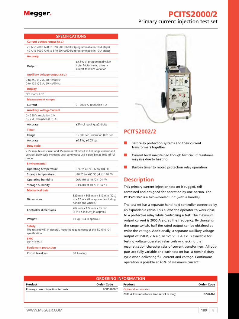
189 8WWW.mEggER.com
PCITS2000/2Primary current injection test set
PCITS2002/2
n Test relay protection systems and their current transformers together
n Current level maintained though test circuit resistance may rise due to heating
n Built-in timer to record protection relay operation
DescriptionThis primary current injection test set is rugged, self-
contained and designed for operation by one person. The
PCITS2000/2 is a two-wheeled unit (with a handle).
The test set has a separate hand-held controller connected by
an expandable cable. This allows the operator to work close
to a protective relay while controlling a test. The maximum
output current is 2000 A a.c. at line frequency. By changing
the range switch, half the rated output can be obtained at
twice the voltage. Additionally, a separate auxiliary voltage
output of 250 V, 2 A a.c. or 125 V, 2 A a.c. is available for
testing voltage operated relay coils or checking the
magnetisation charac teristics of current trans formers. All out-
puts are fully variable and each test set has a nominal duty
cycle when delivering full current and voltage. Continuous
operation is possible at 40% of maximum current.
Ordering infOrmatiOnProduct Order Code
Primary current injection test sets PCITS2000/2
Product Order Code
Optional accessories
2000 A low inductance lead set (3 m long) 6220-462
Current output ranges (a.c.)
20 A to 2000 A (0 to 3 V) 50 Hz/60 Hz (programmable in 10 A steps)40 A to 1000 A (0 to 6 V) 50 Hz/60 Hz (programmable in 10 A steps)
accuracy
Output
±2.5% of programmed valueNote: Motor variac driven - subject to mains variation
auxiliary voltage output (a.c.)
0 to 250 V, 2 A, 50 Hz/60 Hz0 to 125 V, 2 A, 50 Hz/60 Hz
display
Dot matrix LCD
measurement ranges
Current 0 - 2000 A, resolution 1 A
auxiliary voltage/current
0 - 250 V, resolution 1 V0 - 2 A, resolution 0.01 A
Accuracy ±3% of reading, ±2 digits
timer
Range 0 - 600 sec, resolution 0.01 sec
Accuracy ±0.1%, ±0.05 sec
duty cycle
21/2 minutes on circuit and 15 minutes off circuit at full range current and voltage. Duty cycle increases until continuous use is possible at 40% of full range.
environmental
Operating temperature 0 ºC to 40 ºC (32 to 104 ºF)
Storage temperature -20 ºC to +60 ºC (-4 to 140 ºF)
Operating humidity 90% RH at 40 ºC (104 ºF)
Storage humidity 93% RH at 40 ºC (104 ºF)
mechanical data
Dimensions320 mm x 305 mm x 510 mm (121/2 in x 12 in x 20 in approx.) excluding handle and wheels.
Controller dimensions202 mm x 127 mm x 55 mm(8 in x 5 in x 21/8 in approx.)
Weight 61 kg (134 lb approx.)
Safety The test set will, in general, meet the requirements of the IEC 61010-1 specification.
emCIEC 61326-1
equipment protection
Circuit breakers 30 A rating
SPeCifiCatiOnS
8 190 T: +44 (0) 1304 502100 E: [email protected]
Optional Accessories
AA-90165HCP2000 High current probe
For use with INgVAR, oDEN AT, oDEN
BH-90130Current transformer switchbox
For use with INgVAR, oDEN AT
BH-90120Mains adapter 240/400 V
For use with oDEN A, oDEN AT
Multi-cable high current cable set6 x 120 mm2
For use with INgVAR
BH-90102High current serial bar
For use with oDEN AT, oDEN
BE-29090TM200 External timer
For use with oDEN A, cSU600A-AT
BH-90171High current parrel bars
For use with oDEN A, oDEN AT

191 8WWW.mEggER.com
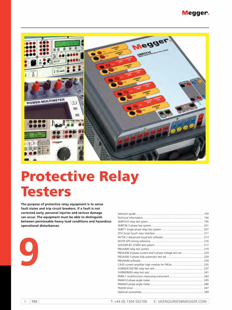
9 192 T: +44 (0) 1304 502100 E: [email protected]
Selection guide ......................................................................................... 193Technical information ................................................................................ 194SMRT410 relay test sytem ......................................................................... 195SMRT36 3 phase test system ..................................................................... 201SMRT1 Single phase relay test system ....................................................... 207STVI Smart touch view interface ................................................................ 211AVTS4.1 Advanced visual test software ..................................................... 213MGTR GPS timing reference ...................................................................... 216GooSeR IeC 61850 test system ................................................................ 217FReJA400 relay test system ....................................................................... 219FReJA306 6 phase current and 3 phase voltage test set ............................. 224FReJA300 3 phase fully automatic test set ................................................. 229FReJAWIN software ................................................................................... 234CA30 current amplifier high module for FReJA .......................................... 235SVeRkeR750/780 relay test sets ................................................................ 237SVeRkeR650 relay test sets ....................................................................... 241PMM-1 multifunction measuring instrument ............................................. 243PAM410 phase angle meter ...................................................................... 245PAM420 phase angle meter ...................................................................... 246TM200 timer ............................................................................................. 247optional accessories .................................................................................. 249
The purpose of protective relay equipment is to sense fault states and trip circuit breakers. If a fault is not corrected early, personal injuries and serious damage can occur. The equipment must be able to distinguish between permissable heavy load conditions and hazardous operational disturbances.
Protective Relay Testers
9

193 9WWW.mEggEr.com
SELECTION GUIDE
n f
eatu
re
£ o
pti
on
SMRT
410
SMRT
36SM
RT1
STV
1A
VTS
4.1
Go
oSe
RM
GTR
FReJ
A40
0FR
eJA
306
FReJ
A30
0C
A30
FReJ
A
WIN
SVeR
keR
750/
780
SVeR
keR
650
SVeR
keR
WIN
PMM
-1PA
M41
0/42
0
TM20
0
Mul
ti ph
ase
test
sy
stem
n
3 ph
ase
fully
au
tom
atic
tes
t sy
stem
nn
nn
6 ph
ase
curr
ent
and
3 ph
ase
volta
ge t
est
syst
em
nn
Dyn
amic
m
anua
l 3 p
hase
te
st c
apab
ility
n
Rela
y te
stin
g so
ftw
are
nn
nn
Sing
le p
hase
re
lay
test
set
n
nn
IeC
618
50 t
est
syst
emn
nn
££
££
GPS
tim
e sy
nchr
onis
atio
nn
nn
nn
exte
rnal
cur
rent
am
plifi
ern
Mul
tifun
ctio
n m
easu
ring
inst
rum
ent
n
Phas
e an
gle
met
ern
n
Tim
ern
n
If y
ou
need
...
limit
ed p
rote
ctiv
e re
lay
test
fu
nct
ion
alit
y m
any
Meg
ger
pro
du
cts
hav
e p
rote
ctiv
e re
lay
test
cap
abili
ty in
clu
din
g e
qu
ipm
ent
fro
m o
ur
pri
mar
y in
ject
ion
tes
t, c
ircu
it b
reak
er, c
urr
ent
tran
sfo
rmer
, cir
cuit
bre
aker
an
alys
is
and
rel
ay t
est
set
ran
ges
. See
sec
tio
ns
on
OD
EN, I
NG
VA
R, C
SU, M
S2A
, SM
RT
FREJ
A, S
VER
KER
, MA
GN
US,
EG
IL, T
M a
nd
MC
T ra
ng
es f
or
mo
re in
form
atio
n.
9 194 T: +44 (0) 1304 502100 E: [email protected]
Testing protective relays
SMRT Family of relay test systems
The SMRT family of units is the “smart” relay test sets designed to
test the “smart grid” relays.
SMRT1 – Single phase relay test set:
n Small, lightweight, high power single phase relay test system
n Regulated high output power for testing electro-mechanical
relays, and high accuracy to test microprocessor relays
n Single phase up to 75 Amps high current capacity for testing
instantaneous trip elements
n Voltage channel provides 0 – 300 Volts AC or DC at 150 VA/
Watts
n 15Amps convertible voltage channel for testing current
differential high slope characteristics
n Manual testing with optional Smart Touch View Interface (STVI)
n Fully automated testing using AVTS software
n Ability to string multiple units together with an ethernet cable
for multi-phase testing
n Network interface provides IEC 61850 test capabilities
SMRT400 series – Multi phase relay test set:
SMRT400
n Small, rugged, lightweight and powerful
n Operates with or without a computer
n Intuitive manual operation with Smart Touch View Interface
n High current, high power output (60 Amps/300 VA rms) per
phase
n Flexible output design provides up to four-phase voltage and up
to ten-phase current
n Network interface provides IEC 61850 test capabilities
n Fully automated testing using AVTS software
SMRT36 – Three phase relay test set:
SMRT36 with 3 x 300 V plus 6 x 60 Amps
n Small, rugged, lightweight and powerful three phase test
system
n High current, high power (60 Amps/300 VA rms) per phase
n Voltage channels provide 0 – 300 Volts AC or DC at 150 VA/
Watts per phase
n Convertible voltage channels provide 15 Amps per phase for 6
Phase testing applications
n Operates with or without a computer
n Intuitive manual operation with Smart Touch View Interface
(STVI)
n Fully automated testing using AVTS software
n Network interface provides IEC 61850 test capabilities
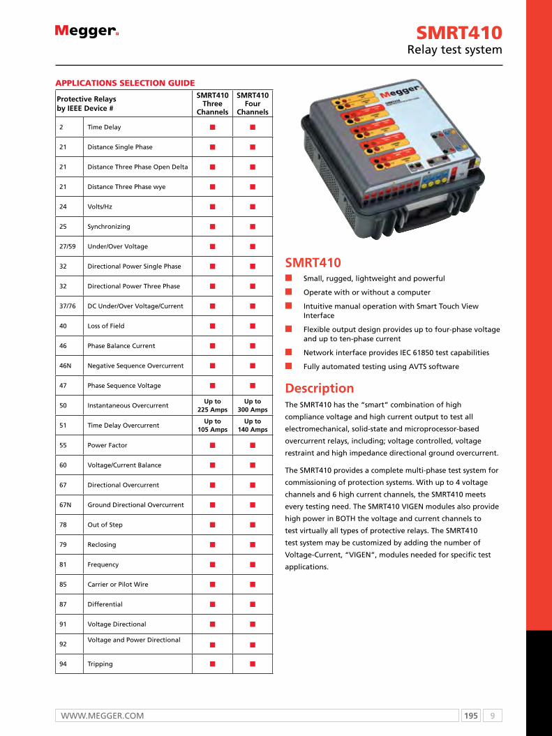
195 9WWW.mEggEr.com
SMRT410n Small, rugged, lightweight and powerful
n Operate with or without a computer
n Intuitive manual operation with Smart Touch View Interface
n Flexible output design provides up to four-phase voltage and up to ten-phase current
n Network interface provides IEC 61850 test capabilities
n Fully automated testing using AVTS software
DescriptionThe SMRT410 has the “smart” combination of high
compliance voltage and high current output to test all
electromechanical, solid-state and microprocessor-based
overcurrent relays, including; voltage controlled, voltage
restraint and high impedance directional ground overcurrent.
The SMRT410 provides a complete multi-phase test system for
commissioning of protection systems. With up to 4 voltage
channels and 6 high current channels, the SMRT410 meets
every testing need. The SMRT410 VIGEN modules also provide
high power in BOTH the voltage and current channels to
test virtually all types of protective relays. The SMRT410
test system may be customized by adding the number of
Voltage-Current, “VIGEN”, modules needed for specific test
applications.
SMRT410relay test system
ApplicATionS SelecTion Guide
Protective Relays by IEEE Device #
SMRT410 Three
Channels
SMRT410 Four
Channels
2 Time Delay n n
21 Distance Single Phase n n
21 Distance Three Phase Open Delta n n
21 Distance Three Phase wye n n
24 Volts/Hz n n
25 Synchronizing n n
27/59 Under/Over Voltage n n
32 Directional Power Single Phase n n
32 Directional Power Three Phase n n
37/76 DC Under/Over Voltage/Current n n
40 Loss of Field n n
46 Phase Balance Current n n
46N Negative Sequence Overcurrent n n
47 Phase Sequence Voltage n n
50 Instantaneous OvercurrentUp to
225 AmpsUp to
300 Amps
51 Time Delay OvercurrentUp to
105 AmpsUp to
140 Amps
55 Power Factor n n
60 Voltage/Current Balance n n
67 Directional Overcurrent n n
67N Ground Directional Overcurrent n n
78 Out of Step n n
79 Reclosing n n
81 Frequency n n
85 Carrier or Pilot Wire n n
87 Differential n n
91 Voltage Directional n n
92Voltage and Power Directional
n n
94 Tripping n n

9 196 T: +44 (0) 1304 502100 E: [email protected]
SPECIFICATIONSSPECIFICATIONS
2 PowerV™ output current varies depending on the voltage setting on the 150 Volt range, see curve.
Input power100 to 240 Volts (± 10%) AC, 1Ø, 50/60 Hz, 1800 VA
Outputs2
All outputs are independent from sudden changes in mains voltage and frequency, and are regulated so changes in load impedance do not affect the output. All amplifier outputs are isolated or floating. The SMRT units can be ordered with the amplifier common returns tied to chassis ground as an option.
Output current source
The SMRT410 with five modules can provide up to ten current sources; six high current/high power3, and four convertible channels providing lower current/high power. The per channel output current and power ratings are specified in AC rms values and peak power ratings.Output current Power Max V / Duty cycle1 Ampere 15 VA 15.0 Vrms Continuous4 Amperes 200 VA (282 peak) 50.0 Vrms Continuous15 Amperes 200 VA (282 peak) 13.4 Vrms Continuous30 Amperes 200 VA (282 peak) 6.67 Vrms Continuous60 Amperes 300 VA (424 peak) 5.00 Vrms 90 CyclesDC 200 Watts
With three currents in parallel:Output volts Power Max I12 Amperes 600 VA (848 peak) 50.0 Vrms Continuous45 Amperes 600 VA (848 peak) 13.4 Vrms Continuous90 Amperes 600 VA (848 peak) 6.67 Vrms Continuous180 Amperes 900 VA (1272 peak) 5.00 Vrms 90 Cycles
With two currents in series:The compliance voltage doubles to provide 4.0 Amperes at 100 Volts rms.
Current amplifier - Extended power rangeThe SMRT current amplifier provides a unique flat power curve from 4 to 30 Amperes per phase to permit testing of electromechanical high impedance relays, and other high burden applications, with an extended operating range up to 60 Amperes at 300 VA rms.
AC voltage outputOutputs are rated with the following ranges:Output volts Power Max I30 Volts 150 VA 5 Amps150 Volts 150 VA Variable2 300 Volts 150 VA 0.5 AmpsDC 150 WattsDuty cycle: Continuous
SMRT410relay test system
ApplicATionS SelecTion Guide
1. Binary Outputs 1 and 2: Rated for 300 V at 8 Amps.
2. Binary Inputs 1 and 2: Rated 5 to 300 V AC/DC
3. Voltage Outputs: Up to 4 channels 300 V at 150 VA,
convertible to currents 15 A at 120 VA per phase.
4. Current Outputs: Up to 6 channels 60 Amps at 300 VA per
phase.
5. USB 2.0 Interface: Communication and control port.
6. Additional Binary Inputs: Provides 8 additional monitor
circuits.
7. Rugged Case: Fiberglass reinforced plastic.
8. PC/OUT: ethernet Port is the primary PC connection port.
ethernet Port used to chain multiple SMRT units together for
synchronous multi-unit operation.
9. Additional Binary Outputs: Adds 4 outputs. Binary
outputs 3 and 4 are rated for 300 V AC/DC, 8 amperes. Binary
outputs 5 and 6 are high speed and have an AC/DC voltage
rating of 400 volts peak, 1 ampere.
10. IN/61850: This port may also be used for connecting to the
IeC 61850 substation bus for testing IeC 61850 devices.
11. STVI: ethernet Port is a Poe (Power over ethernet) port and is
used to connect to the STVI for manual control.
12. Battery Simulator: Variable 5 to 250 Volts DC output at
100 Watts (4 amperes maximum).
13. Incoming Power/Line Cord Socket: 100 to 240 V,
50/60 Hz.
14. POWER ON/OFF Switch: Illuminates when power is on.
15. Protective Earth Ground Jack.16. Bluetooth: Bluetooth® provides wireless control.
SMRT410 RelAy TeSTeR
32
1
16
15
14
13
12111098
7
6
5
4

197 9WWW.mEggEr.com
PowerV™ voltage amplifier - extended power range The SMRT voltage amplifier provides a flat power curve from 30 to 150 Volts in the 150 V range to permit testing of high current applications such as panel testing.
Voltage amplifier in current mode:Output current Power Max V Duty Cycle5 Amperes 150 VA (212 peak) 30.0 Vrms Continuous15 Amperes 120 VA 8.0 Vrms 90 Cycles
Phase angleRanges 0.00 to 359.99 degrees, Counter Clock Wise, or Clock Wise rotation, or 0.00 to ±180.00 degreesAccuracy: ± 0.02° typical, ± 0.25° max at 50/60 Hz
FrequencyThe output modules provide a variable frequency output with the following ranges and accuracy.RangesDC0.001 to 1000.000 HzOutput amplifiers can provide transient signals with a range of DC to 10 kHz for transient playback using COMTRADE files.Resolution*: .0001/.001 HzFrequency accuracy:2.5 ppm typical25 ppm 0° to 50 °C, at 50/60 Hz Maximum
Total harmonic distortionLess than 0.1% typical, 2% maximum at 50/60 Hz
TimerThe Timer-Monitor Input is designed to monitor and time-tag inputs, like a sequence of events recorder. In addition, the binary input controls enable the user to perform logic AND/oR functions, and conditionally control the binary output relay to simulate circuit breaker, trip, reclose and carrier control operation in real-time. The timer function displays in Seconds or cycles, with the following range and resolution:Seconds: 0.0001 to 99999.9(Auto ranging)Cycles: 0.01 to 99999.9(Auto ranging)Accuracy: ±0.001% of reading, typical. ±2 least significant digit,±0.005% of reading from 0 to 50° C maximum
Binary Input – Start/stop/monitor gateTo monitor operation of relay contacts or trip SCR, continuity light is provided for the input gate. Upon sensing continuity the lamp will glow. In addition to serving as wet/dry contacts the binary inputs may be programmed to trigger binary output sequence(s). Input rating: up to 300 V AC/DC
Binary output relays SMRT36 has independent, galvanically isolated, output relay contacts to accurately simulate relay or power system inputs to completely test relays removed from the power system. The binary output simulates normally open / normally closed contacts for testing breaker failure schemes. The binary output can be configured to change state based on binary input logic.High current output relays: The first two VIGeN modules have1 each, and the SMRT36 “P” model adds 2 more.AC rating: 400 V max., Imax: 8 amps, 2000 VA max. DC rating: 300 V max., Imax: 8 amps, 80 WResponse time: <10 msHigh speed output relays: SMRT36 “P” Model adds 2AC/DC rating: 400 V peak, Imax: 1 ampResponse time: <1 ms typical
1 Megger reserves the right to change product specifications at any time.2 For 4 or 5 channel units operating at input voltages below 220 VAC a derating of the simultaneously available total outputpower of the voltage/current amplifiers and battery simulator will occur. The maximun output power of a single amplifier is not affected.3 Six high current/high power channels require optional DIGEN, Double Current Generation, see Ordering Information for details.4 PowerVTM voltage amplifier output current varies depending on the voltage setting on the 150 Volt range, see curve.
Battery simulatorThe SMRT410 with the P (Plus) option includes a battery simulator with a variable DC output voltage ranging from 5 to 250 Volts at 100 Watts, 4 Amps max, providing capability to power up relays with redundant power supplies. Voltage output is controlled via the Smart Touch-View Interface, or through AVTS software. The SMRT410 with the N option does not include a battery simulator.
Waveform generation each output channel can generate a variety of output waveforms such as: DC; sine wave; sine wave with percent harmonics at various phase angles; half waves; square waves with variable duty cycles; exponential decays; periodic transient waveforms from digital fault recorders, relays with waveform recording capability or eMTP/ATP programs, which conform to the Ieee C37.111 CoMTRADe standard format.
Metering Measured output quantities such as AC Amperes, AC Volts, DC Volts or DC Amperes, and Time may be simultaneously displayed on the large, color TFT LCD touch screen. The AC and DC outputs display the approximate voltage/current output prior to initiation of the outputs. All accuracies stated our from 10 to 100% of the range at 50/60 Hz.
AC voltage amplitude
Accuracy±0.05% reading + 0.02% range typical, ±0.15% reading + 0.05% range maximum
Resolution .01
Measurement AC RMS
Ranges 30, 150, 300 V
AC current amplitude
Accuracy±0.05 % reading +0.02% range typical, ±0.15% reading +0.05% range maximum
Resolution .001/.01
Measurement AC RMS
Ranges 30, 150, 300 V
DC voltage amplitude
Accuracy0.1% range typical,0.25% range maximum
Resolution 0.1
Measurement RMS
Range 30, 150, 300 V
DC current amplitude
Accuracy0.1% range typical,0.25% range maximum
Resolution 0.1
Measurement RMS
Ranges 30 A
Convertible source in AC current mode
Accuracy
±0.05% reading +0.02% range typical, ±0.15% reading +0.05% range or ±12.5 mA whichever is greater
Resolution .001
Measurement AC RMS
Range 5, 15 A
Environmental
Operating temperature 0 ºC to 50 °C (32 °F to 122 °F)
Storage temperature -25 ºC to 70 ºC (-13 °F to 158 ºF)
Relative humidity 5 - 90% RH, Non-condensing
SMRT410relay test system
9 198 T: +44 (0) 1304 502100 E: [email protected]
Unit enclosureThe SMRT unit comes housed in a rugged, virtually indestructible, lightweight and ergonomic enclosure. It features a large oversized rubber cushioned handle, and removable lid for use in tight spaces.
Dimensions
With the lid on360 W x 194 H x 413 D mm(14.2 W x 7.6 H x 16.25 D in.)
With the lid off360 W x 180 H x 413 D mm (14.2 W x 7.2 H x 16.25 D in.)
IEC enclosure rating IP20
Weight
With the transit lid on 17.76 kg (39.5 lb.)
With the transit lid off 16.4 kg (36.5 lb.)
Conformance standard
Safety EN 61010-1
ShockMIL-PRF-28800F (30g/11ms half-sine)
VibrationMIL-RFP-28800F (5-500Hz, 2.05 g rms)
Translt dropMIL-RFP-28800F (10 drops, 46 cm)
Protection
Voltage outputs are protected from short circuits and thermallyprotected against prolonged overloads. Current outputs areprotected against open circuits and thermally protected againstprolonged overloads.
Communication interfaces
Ethernet (2)USB 2.0Bluetooth (optional)
SMRT410relay test system
SOFTWARE
AVTS - STVI Basic
Every unit comes with AVTS Basic software and the PC version of the STVI Basic software packages. AVTS Basic version includes Online Vector control (for single and multi-state timing tests), Online Ramp control (for automatic ramping of voltage, current, phase angles or frequency) and Online Click-On-Fault (for dynamic tests of impedance relays). Test results may be exported directly to Microsoft Word. AVTS software includes a database for saving testresults, which can also provide the necessary information needed for system reliability audits. See AVTS bulletin for more information.
The PC version of the STVI software includes the ability to bring all STVI test data (from other STVI units) into file folders for retrieval, review and printing whenever needed. See STVI bulletin for more information.
AVTS Advanced
The AVTS Advanced version includes all the feature in AVTS Basic plus the powerful Test Editor, Dynamic Control (includes dynamic end-to-end testing capability, and waveform recording capability), ASPEN OneLiner™ or Electrocon CAPE™ SS1 File Converter for dynamic testing, and easy to use programming Tools for creating and editing test modules. See AVTS bulletin for more information.
AVTS Professional
The AVTS Professional version includes all of the features of the Basic and Advanced versions plus some other powerful test tools and features. It includes the DFR Waveform Viewer, One-Touch™ Test for fully automatic tests, Modbus communication test capability, and Waveform Digitizer to digitize scanned waveformsof electromechanical over current time curves. See AVTS bulletin for more information.
IEC 61850 GOOSE
The SMRT with the GOOSE enabled, in conjunction with the Megger GOOSE Configurator (MGC) software, can be used in the testing or commissioning of IEC 61850 compliant devices. See AVTS bulletin for more information.
included STAndARd AcceSSoRieS
deScRipTion part number
Power Cord - Depending on the style number, the unit will come with one of the following,
Line cord, North American 620000
Line cord, Continental Europe with CEE 7/7 Schuko Plug 50425
Line cord, International color coded wire 15065
Line cord, United Kingdom 90002-989
Ethernet crossover cable for interconnection to PC, 210cm (7 ft.) long (Qty. 1 ea) 90003-684
Instruction manual CD 80989
199 9WWW.mEggEr.com
SMRT410relay test system
For more informationon smrT410, including all the optional accessories
Visit our website - www.megger.com
Optional Accessories Descriptions
STVI, or Binary I/O Bat SIM, or Test Leads
Options
Three (3) Voltage Current Modules
Four (4) Voltage Current Modules
With DIGEN
or VIGEN Module1
Binary I/O, Battery
Simulator Option
Accessory Carry Case: Use to carry power cord, Ethernet cable, Optional STVI and test leads.
Qty. 1 ea. Part No. 2001-487
Sleeved Pair of Test Leads: Keeps the test leads in pairs and from getting entangled.Sleeved Test Leads, one red, one black, 200 cm (78.7”) long, 600 V, 32 Amperes CAT II.*
Qty. 3 pr. Part No. 2001-394
Qty. 4 pr. Part No. 2001-394
Qty. 2 pr. Part No. 2001-394
Qty. 3 pr. Part No. 2001-394
Cable/Spade Lug Adapter (Small): Small lug fit most new relay small terminal blocks.Lug adapter, red, 4.1 mm, use with test leads up to 1000 V/ 20 Amps CAT II.
Qty. 3 ea.Part No.684004
Qty. 14 ea.Part No.684004
Qty. 2ea.Part No.684004
Qty. 3 ea.Part No.684004
Lug adapter, black, 4.1 mm, use with test leads up to 1000 V/ 20 Amps CAT II.
Qty. 3 ea.Part Num-
ber684005
Qty. 14 ea.Part Num-
ber684005
Qty. 2ea.Part Num-
ber684005
Qty. 3 ea.Part Num-
ber684005
Jumper Lead: Used to common returns together on units with floating ground returns, or parallel of current channels. Jumper lead, black, 12.5 cm (5”) long, use with voltage / current outputs, 600 V, 32 Amps CAT II.
Qty. 4 ea.Part Num-
ber2001-573
Qty. 6 ea.Part Num-
ber2001-573
Sleeved Combination Voltage Test Leads: Keeps the test leads from getting entangled. Three common leads connect to the test set, which are interconnected down to one black common to connect to the relay under test. Sleeved Three Phase Test Leads, three red and black, 200 cm (78.7”) long, 600 V, 32 Amperes CAT II.*
Qty. 1 ea.Part Num-
ber2001-395
Qty. 1 ea.Part Num-
ber2001-395
Sleeved Combination Current Test Leads: Keeps the test leads from getting entangled. Three pairs of leads connect to the test set, with three pairs to connect to the relay under test. Sleeved Three Phase Test Leads, three red and black, 200 cm (78.7”) long, 600 V, 32 Amperes CAT II.*
Qty. 1 ea.Part Num-
ber2001-396
Qty. 1 ea.Part Num-
ber2001-396
Note that the sleeved “combination” leads come with either the three, or four Voltage/Current module configurations only.1Adding the DIGEN or VGEN module adds the extra leads and spades lugs as shown in the column.*600V, 32 Amperes, CAT IV available as an option.
Table of AccessoriesAccessories are supplied with the selection of the test leads option, and/or the Binary Input/output/Battery Simulator option, and/or the STVI option. With the test leads option the number and type
of leads varies depending on the number of channels ordered. If desired, test leads and accessories can be ordered individually, see description and part numbers below.

9 200 T: +44 (0) 1304 502100 E: [email protected]
oRdeRinG inFoRMATion
Model SMRT410 -
Voltage/Current Modules Enter 3 or 4
Base Unit OptionsN = No Extra Binary I/OP = Plus Binary I/O & Battery Simulator
Common Returns OptionF = Floating Ungrounded ReturnsG = Grounded Common Returns Bluetooth Option
1 = With Bluetooth 0 = Without
Test Leads Option1 = With Leads 0 = Without Leads
Hardware OptionsS = Standard unit
IEC61850 Option0 = Without 1 = With IEC 61850 GOOSE Enabled
Power Cord OptionA = North American Power Cord I = International Power Cord E = Continental Europe Power CordU = United Kingdom
STyle nuMbeR idenTiFicATion
Smart Touch View Interface Option 1 = With STVI 0 = Without
deScRipTion oF SoFTwARe opTionS
included Software part number
AVTS Basic with STVI Application CD 81302
Software Options
AVTS Basic with IEC 61850 Megger GOOSE Configurator, and STVI Application CD 1002-103
AVTS Advanced with STVI Application CD 81570
AVTS Advanced Test with IEC 61850 Megger GOOSE Configurator, and STVI Application CD 1001-106
AVTS Professional with STVI Application CD 81571
AVTS Professional Test with IEC 61850 Megger GOOSE Configurator, and STVI Application CD 1002-102
deScRipTionS oF HARdwARe opTionS
This modular system lets you select the testing capabilities you need now and expand as testing requirements change. Customize the system by adding the number of Voltage-Current amplifier (VIGEN) modules (3 or 4), with optional Double-Current (DIGEN) module. For example, start with the base unit of 3 VIGEN modules. For more demanding tests, start with 4 VIGENS, and add a DIGEN to provide 4 Voltages, 6 Currents simultaneously, with convertible voltage channels up to 10 Currents.
Voltage/Current Module: The SMRT410 unit can have either 3 or 4 voltage/current modules. Enter the number of desired modules 3, or 4.
Double Current or 4th Voltage1 Module: The SMRT410 5th and last slot can be a Double Current (DIGEN) Module. Enter the number 1 for the unit to come with the DIGEN. The 4th slot can host a single Voltage Channel for those who want a 4th voltage channel in ad-dition to 3 Voltage/Current modules. Enter the number 2 for this option.
Base Unit Options: The first two channels provide 1 binary input and 1 binary output each. Enter N for No extra binary I/O or battery simulator. Note the 4th voltage channel can be used as the Battery Simulator. For the user who requires the extra binary inputs, outputs and battery simulator enter P for Plus option.
Smart Touch View Interface Option: Enter 1 for the unit to come with the STVI, or enter the number 0 for without.
Common Returns Option: Enter F for floating returns and G for grounded common returns. The floating returns option provides independent, isolated return terminals for each output channel.
The G option provides grounded common returns, where return terminals are connected internally to chassis ground.
Power Cord Option: Customers can choose which type of power cord they want the unit to come with. • A Option – NEMA 5-15 to IEC60320 C13 connectors,
UL & CSA approved for countries with NEMA outlets.• I Option - International color coded wires (light blue, brown and
green with yellow stripe) insulation jacket stripped ready for male connector with IEC 60320 C13 connector. CE marked.
• E Option - CEE 7/7 “Schuko” plug to IEC 60320 C13 connector is CE marked.
• U Option - United Kingdom power cord with IEC 60320 C13 connector, and 13 Amp fuse. BS 1363/CE Marked.
Bluetooth Option: For customers who wish to have a wireless control of the SMRT unit, enter the number 1 for the unit to come with the Bluetooth option installed. Enter 0 for without.
IEC 61850 Option: The SMRT410 in conjunction with the Megger GOOSE Configurator (MGC) software can be used in the testing or commissioning of IEC 61850 compliant devices. In order for the SMRT410 to be able to subscribe as well as publish GOOSE messages, the IEC 61850 feature needs to be enabled. Enter the number 1 for the unit to come with the IEC 61850 option enabled. Enter 0 for the unit without IEC 61850 enabled.
Option: S = Standard unit.
Test Leads Options: Enter the number 1 for the unit to come with Test Leads. Enter 0 for the unit without Test Leads.
Double Current or 4th Voltage ModulesEnter 1 for Double CurrentEnter 2 or 4th Voltage Channel1
0 = Without
SMRT410relay test system

201 9WWW.mEggEr.com
SPECIFICATIONS
SMRT36n Small, rugged, lightweight and powerful
n Operate with or without a computer
n Intuitive manual operation with Smart Touch View Interface
n High current, high power (60 Amps/300 VA rms) per phase
n Network interface provides IEC 61850 test capabilities
n Fully automated testing using AVTS software
DescriptionThe SMRT is the next generation of Megger programmable
secondary relay test systems designed specifically to test
microprocessor, solid state, and electromechanical relays. The
SMRT36 may be customized by adding the number of voltage-
current channels, “VIGEN” modules, needed for specific test
applications (see Applications Selection).
The SMRT36 test system has the ability to be manually
controlled with Megger’s new Smart Touch View Interface™
(STVI). The STVI, with its large, full color, high resolution, TFT
LCD touch screen allows the user to perform manual, steady-
state and dynamic testing quickly and easily using the manual
test screen, as well as using built-in preset test routines for
most popular relays.
The STVI eliminates the need for a computer when testing
virtually all types of relays. Menu screens and touch screen
function buttons are provided to quickly and easily select the
desired test function. Tests results can be saved to the STVI for
download to a memory stick to transfer or print test reports.
For full automatic testing the SMRT36 may be controlled
by Megger Advanced Visual Test Software (AVTS). AVTS is
a Microsoft® Windows® XP®/Vista™/7 compatible software
program designed to manage all aspects of protective relay
testing using the new Megger SMRT.
Protective relays by iEEE Device #
smrT 36single
channel
smrT 36Two
channels
smrT 36Three
channels
2 Time delay n n n
21 Distancesingle phase
n n n
21 Distance three phaseopen Delta
n n
21 DistanceThree phase wye
n
24 Volts/Hz n n n
25 synchronizing n n
27/59 under/over voltage n n n
32 Directional powersingle Phase
n n n
32 Directional powerthree phase (open Delta)
n n
37/76 Dc under/overvoltage/current
n n n
40 Loss of field n n n
46 Phase balance current n n n
46n negative sequence overcurrent
n n n
47 Phase sequencevoltage (open Delta)
n n
50 instantaneousovercurrent
up to 75 Amps
up to 150
Amps
up to 225 Amps
51 Time delay overcurrent
up to 35 Amps
up to 70 Amps
up to 105 Amps
55 Power factor n n n
60 Voltage / current balance (open Delta)
single Phase
n n
67 Directional overcurrent
n n n
67n ground directional overcurrent
n n n
78 out of step n n n
79 reclosing n n n
81 Frequency n n n
85 carrier or pilot wire n n n
87 Differential n n n
91 Voltage directional
(open Delta) n n
92 Voltage and power Directional (open Delta)
n n
94 Tripping n n n
Applications guide
Model STV1
SMRT36relay test system

9 202 T: +44 (0) 1304 502100 E: [email protected]
SMRT36relay test system
SPECIFICATIONS
Input power100 to 240 Volts (± 10%) AC, 1Ø, 50/60 Hz, 1800 VA
Outputs
All outputs are independent from sudden changes in mains voltage and frequency, and are regulated so changes in load impedance do not affect the output. Amplifier outputs are available fully isolated or with grounded common returns.
Output current source
The SMRT36 with three VIGEN modules can provide up to six current sources; three high current/high power, and three convertible channels providing lower current/high power. The per channel output current and power ratings are specified in AC rms values and peak power ratings.Output current Power Max V / Duty cycle1 Ampere 15 VA 15.0 Vrms Continuous4 Amperes 200 VA (282 peak) 50.0 Vrms Continuous15 Amperes 200 VA (282 peak) 13.4 Vrms Continuous30 Amperes 200 VA (282 peak) 6.67 Vrms Continuous60 Amperes 300 VA (424 peak) 5.00 Vrms 90 CyclesDC 200 Watts
With three currents in parallel:Output volts Power Max I12 Amperes 600 VA (848 peak) 50.0 Vrms Continuous45 Amperes 600 VA (848 peak) 13.4 Vrms Continuous90 Amperes 600 VA (848 peak) 6.67 Vrms Continuous180 Amperes 900 VA (1272 peak) 5.00 Vrms 90 Cycles
With two currents in series:The compliance voltage doubles to provide 4.0 Amperes at 100 Volts rms.
Current amplifier - Extended power rangeThe SMRT current amplifier provides a unique flat power curve from 4 to 30 Amperes per phase to permit testing of electromechanical high impedance relays, and other high burden applications, with an extended operating range up to 60 Amperes at 300 VA rms.
AC voltage outputOutputs are rated with the following ranges:Output volts Power Max I30 Volts 150 VA 5 Amps150 Volts 150 VA Variable2 300 Volts 150 VA 0.5 AmpsDC 150 WattsDuty cycle: Continuous
SPECIFICATIONS123
4
5
6
7
8 9 10 11 12 13
14
15
16
1. Binary outputs 1 and 2: Rated for 300 V at 8 Amps.
2. Binary inputs 1 and 2: Rated 5 to 300 V AC/DC
3. Voltage outputs: Up to 3 channels 300 V at 150 VA, convertible to currents 15 A at 120 VA per phase.
4. Current outputs: Up to 3 channels 60 Amps at 300 VA per phase. Up 180 Amps at 900 VA single phase.
5. USB 2.0 interface: Communication and control port.
6. Additional binary inputs: Provides 8 additional monitor circuits.
7. Rugged case: Polymeric material.
8. PC/61850 Ethernet port is the primary PC connection port. This port may also be used for connecting to the IEC 61850 substation bus for testing IEC 61850 devices.
9. Additional binary outputs: Adds 4 outputs. Binary outputs 3 and 4 are rated for 300 V AC/DC, 8 amperes. Binary outputs 5 and 6 are high speed and have an AC/DC voltage rating of 400 volts peak, 1 ampere.
10. OUT: Ethernet port used to chain multiple SMRT units together for synchronous multi-unit operation.
11. STVI: Ethernet port is a PoE (Power over Ethernet) port and is used to connect to the STVI for manual control.
12. Battery simulator: Variable 5 to 250 Volts DC output at 100 Watts (4 amperes maximum).
13. Incoming power / Line cord socket: 100 to 240 V, 50/60 Hz.
14. Protective earth ground jack.
15. POWER ON/OFF Switch: Illuminates when power is on.
16. Bluetooth: Bluetooth® provides wireless control.
2 PowerV™ output current varies depending on the voltage setting on the 150 Volt range, see curve.

203 9WWW.mEggEr.com
SMRT36relay test system
PowerV™ voltage amplifier - extended power range The SMRT voltage amplifier provides a flat power curve from 30 to 150 Volts in the 150 V range to permit testing of high current applications such as panel testing.
Voltage amplifier in current mode:Output current Power Max V Duty Cycle5 Amperes 150 VA (212 peak) 30.0 Vrms Continuous15 Amperes 120 VA 8.0 Vrms 90 Cycles
Phase angleRanges 0.00 to 359.99 degrees, Counter Clock Wise, or Clock Wise rotation, or 0.00 to ±180.00 degreesAccuracy: ± 0.02° typical, ± 0.25° max at 50/60 Hz
FrequencyThe output modules provide a variable frequency output with the following ranges and accuracy.RangesDC0.001 to 1000.000 HzOutput amplifiers can provide transient signals with a range ofDC to 10 kHz for transient playback using COMTRADE files.Resolution*: .0001/.001 HzFrequency accuracy:2.5 ppm typical25 ppm 0° to 50 °C, at 50/60 Hz Maximum
Total harmonic distortionLess than 0.1% typical, 2% maximum at 50/60 Hz
TimerThe Timer-Monitor Input is designed to monitor and time-tag inputs, like a sequence of events recorder. In addition, the binary input controls enable the user to perform logic AND/oR functions, and conditionally control the binary output relay to simulate circuit breaker, trip, reclose and carrier control operation in real-time. The timer function displays in Seconds or cycles, with the following range and resolution:Seconds: 0.0001 to 99999.9(Auto ranging)Cycles: 0.01 to 99999.9(Auto ranging)Accuracy: ±0.001% of reading, typical. ±2 least significant digit,±0.005% of reading from 0 to 50° C maximum
Binary Input – Start/stop/monitor gateTo monitor operation of relay contacts or trip SCR, continuity light is provided for the input gate. Upon sensing continuity the lamp will glow. In addition to serving as wet/dry contacts the binary inputs may be programmed to trigger binary output sequence(s). Input rating: up to 300 V AC/DC
Binary output relays SMRT36 has independent, galvanically isolated, output relay contacts to accurately simulate relay or power system inputs to completely test relays removed from the power system. The binary output simulates normally open / normally closed contacts for testing breaker failure schemes. The binary output can be configured to change state based on binary input logic.High current output relays: The first two VIGeN modules have 1 each, and the SMRT36 “P” model adds 2 more.AC rating: 400 V max., Imax: 8 amps, 2000 VA max. DC rating: 300 V max., Imax: 8 amps, 80 WResponse time: <10 msHigh speed output relays: SMRT36 “P” Model adds 2AC/DC rating: 400 V peak, Imax: 1 ampResponse time: <1 ms typical
Waveform generation each output channel can generate a variety of output waveforms such as: DC; sine wave; sine wave with percent harmonics at various phase angles; half waves; square waves with variable duty cycles; exponential decays; periodic transient waveforms from digital fault recorders, relays with waveform recording capability or eMTP/ATP programs, which conform to the Ieee C37.111 CoMTRADe standard format.
Metering Measured output quantities such as AC Amperes, AC Volts, DC Volts or DC Amperes, and Time may be simultaneously displayed on the large, color TFT LCD touch screen. The AC and DC outputs display the approximate voltage/current output prior to initiation of the outputs. All accuracies stated our from 10 to 100% of the range at 50/60 Hz.
AC voltage amplitude
Accuracy±0.05% reading + 0.02% range typical, ±0.15% reading + 0.05% range maximum
Resolution .01
Measurement AC RMS
Ranges 30, 150, 300 V
AC current amplitude
Accuracy±0.05 % reading +0.02% range typical, ±0.15% reading +0.05% range maximum
Resolution .001/.01
Measurement AC RMS
Ranges 30, 150, 300 V
DC voltage amplitude
Accuracy0.1% range typical,0.25% range maximum
Resolution 0.1
Measurement RMS
Range 30, 150, 300 V
DC current amplitude
Accuracy0.1% range typical,0.25% range maximum
Resolution 0.1
Measurement RMS
Ranges 30 A
Convertible source in AC current mode
Accuracy
±0.05% reading +0.02% range typical, ±0.15% reading +0.05% range or ±12.5 mA whichever is greater
Resolution .001
Measurement AC RMS
Range 5, 15 A
Environmental
Operating temperature 0 ºC to 50 °C (32 °F to 122 °F)
Storage temperature -25 ºC to 70 ºC (-13 °F to 158 ºF)
Relative humidity 5 - 90% RH, Non-condensing
Dimensions
With the lid on360 W x 194 H x 305 D mm(14.2 W x 7.6 H x 12.0 D in.)
With the lid off360 W x 180 H x 413 D mm (14.2 W x 7.2 H x 16.25 D in.)
IEC enclosure rating IP30
Weight
With the transit lid on 12.25 kg (27.9 lb.)
With the transit lid off 11.6 kg (28.5 lb.)

9 204 T: +44 (0) 1304 502100 E: [email protected]
SMRT36relay test system
Included accessories
Power Cord - depending on the style number, the unit will come with one of the following,
Line cord, North American 620000
Line cord, with CEE 7/7 Schuko Plug
50425
Line cord, international color coded wire 15065
Line cord, United Kingdom 90002-989
Ethernet crossover cableEthernet crossover cable for interconnection to PC, 210 cm (7 ft.) long (Qty. 1 ea)
620094
Instruction manual CD 80989
Deluxe test leads and accessories kitThe test leads and test lead accessories are an option. Test leads and accessories can be ordered with the unit, or later as a kit. The deluxe test leads and accessories kit includes sleeved pairs of leads for use with the extra binary inputs/outputs/battery simulator option, as well as the three phase sleeved combination leads for voltage and current channels. The following test leads and test lead accessories are included in the deluxe test leads and accessories kit in quantities shown.
1001-619
Sleeved combination voltage test leadsKeeps the test leads from getting entangled. Sleeved three phase test leads, three red and black, 200 cm (78.7”) long, 600 V, 32 Amperes CAT II (Qty. 1 ea)
2001-395
Sleeved combination current test leadsKeeps the test leads from getting entangled. Sleeved three phase test leads, three red and black, 200 cm (78.7”) long, 600 V, 32 Amperes CAT II (Qty. 1 ea)
2001-396
Sleeved pair test leadsOne red, one black, 200 cm (78.7”) long, 600 V, 32 Amperes CAT II, (Qty. 5 pair)
2001-394
Jumper leadBlack, 12.5 cm (5”) long, use with voltage/current outputs, 600 V, 32 Amps CAT II (Qty. 4 ea.)
2001-573
Cable/Spade lug adapter (small)Small lug fits most new relay small terminal blocks. Lug adapter, red, 4.1 mm, use with test leads up to 1000 V/ 20 Amps CAT II (Qty. 15 ea.)
684004
Lug adapterBlack, 4.1 mm, use with test leads up to 1000 V/ 20 amps CAT II (Qty. 15 ea.)
684005
Accessory caseBlack, used to carry test leads and /or STV1 (Qty.1)
2001-487
Specification continuedConformance standards
SafetyEN 61010-1, UL 61010-1, CSA- C22.2 #61010-1
Shock, vibration and transit drop
ShockMIL-PRF-28800F (30g/11ms half-sine)
VibrationMIL-RFP-28800F (5-500 Hz, 2.05 g rms)
Transit dropMIL-PRF-28800F (10 drops, 460 m)
Steady cold MIL-STD-810, Method 502.2
Cold storage MIL-STD-810, Method 502.2
Hot storage MIL-STD-810, Method 501.2
Steady dry heat MIL-STD-810, Method 501.2
Electromagnetic compatibility
EmissionsEN 61326-2-1, EN 61000-3-2/3, FCC Subpart B of Part 15 Class A
Immunity EN 61000-4-2/3/4/5/6/8/11
ProtectionVoltage outputs are protected from short circuits and thermally protected against prolonged overloads. Current outputs are protected against open circuits and thermally protected against prolonged overloads.
Communication interfacesEthernet (2), USB 2.0, Bluetooth (optional)
SOFTWARE AVTS – STVI BASIC
Every unit comes with AVTS basic software and the PC version of the STVI basic software packages. AVTS basic version includesonline vector control (for single and multi-state timing tests), online ramp control (for automatic ramping of voltage, current, phase angles or frequency) and online click-on-fault (for dynamic tests of impedance relays). Test results may be exported directly to Microsoft word. AVTS software includes a database for saving test results, which can also provide the necessary information needed for system reliability audits.
The PC version of the STVI software includes the ability to bring all STVI test data (from other STVI units) into file folders for retrieval and review whenever needed.
AVTS advancedThe AVTS advanced version includes the powerful test editor, dynamic control (includes dynamic end-to-end testing capability, and waveform recording capability), Modbus communication test capability, ASPEN OneLiner™ or Electrocon CAPE™ SS1 file converter for dynamic testing, and easy to use programming tools for creating and editing test modules.
AVTS professionalThe AVTS professional version includes all of the features of the basic and advanced versions plus some other powerful test tools and features. It includes the DFR waveform viewer, One-Touch™ Test for fully automatic tests, and waveform digitizer to digitize scanned waveforms of electromechanical over current time curves.
IEC 61850 GOOSEThe SMRT with the GOOSE enabled, in conjunction with the Megger GOOSE Configurator (MGC) software, can be used in the testing or commissioning of IEC 61850 compliant devices.
205 9WWW.mEggEr.com
SMRT36relay test system
SPECIFICATIONSORDERING INFORMATION
Style number identification
Voltage/current modulesEnter 1, 2, or 3
Reserved for Future Use
base unit optionsn = No extra binary inputs / outputsp = Plus binary I/O and battery simulator
Smart touch view interface option 1 = With STVI0 = Without
common returns optionF = Floating ungrounded returnsG = Grounded common returnsc = CE Mark, 220-240 V input, floatinge = CE Mark, 220-240 V input, grounded
bluetooth optionEnter 1 = With Bluetooth option Enter 0 = Without Bluetooth option
power cord optionA = North American power cord i = International power corde = Continental Europe power cordu = United Kingdom power cord
iec61850 option1 = With IEC 61850 GOOSE0 = Without
enclosure optionsS = Standard field enclosure
Test leads option1 = With leads0 = Without leads
Model SMRT36-0 S
Description of software options Part NumberIncluded software AVTS basic with STV1 application CD 81302 Software options AVTS basic with IEC 61850 Megger GOOSE configurator and STV1 application CD 1002-103AVTS advanced with STV1 application CD 81570AVTS advanced test with IEC 61850 Megger GOOSE configurator and STV1 application CD 1001-106AVTS Professional with STV1 application CD 81571AVTS Professional test with IEC 61850 Megger GOOSE configurator and STV1 application CD 100
Descriptions of hardware optionsVoltage/current module: The SMRT 36 unit can have up to a total of 3 voltage/current modules. Enter the number of desired voltage / current modules 1, 2 or 3. Future: 0, Reserved for future use.Base unit options: The first two channels provide 1 binary input and 1 binary output each. Enter N for No extra binary I/O or battery simulator. For the user who requires the extra binary inputs, outputs and/or the battery simulator enter P for Plus option. Smart touch view interface option: Enter the number 1 for the unit to come with the STVI, or enter the number 0 for without. Common returns option: The floating returns option provides independent, isolated return terminals for each output channel. The gournded common returns option, the return terminals are interconnected internally and connected to chasiss ground. The CE mark C and E units are designed to operatue with an input voltage of 220 to 240 volts. the F and G units are designed to operatue with an input of 100 to 240 V.Bluetooth option: For customers, who wish to have a wireless control of the SMRT unit, enter the number 1 for the unit to come with the Bluetooth option, or enter 0 for without. Power cord option: Customers can choose which type of power cord they want the unit to come with. A Option - NEMA 5-15 to IEC60320 C13 connectors, UL and CSA approved for countries with NEMA outlets.I Option - International color coded wries (light blue, brown and green with yellow stripe) insulation jacket stripped ready for male connector is CE marked.E Option - CEE 7/7 “Shuko” plug to IEC 60320 C13 connector, and 13 Amp fuse. CE marked.U Option - United Kingdom power cord with IEC 60320 C13 connector, and 13 Amp fuse. CE marked.Bluetooth Option - For customers who wich to have a wireless control of the SMRT unit, enter the number 1 for the unit to come with the Bluetooth option installed. Enter 0 for without.IEC 61850 option: The SMRT36 in conjunction with the Megger GOOSE Configurator (MGC) software can be used in the testing or commissioning of IEC 61850 compliant devices. In order for the SMRT36 to be able to subscribe as well as publish GOOSE messages, the IEC 61850 feature needs to be enabled. Enter the number 1 for the unit to come with the IEC 61850 option enabled. Enter 0 for the unit without IEC 61850 enabled.Enclosure option: S for Standard, rugged, field type enclosure. Test leads option: Enter the number 1 for the unit to come with test leads. Enter 0 for the unit without test leads.

9 206 T: +44 (0) 1304 502100 E: [email protected]
SMRT36relay test system
STVI, or binary I/O bat SIM, or test leads options
One (1) voltage current module
Two (2) voltage current
modules
Three (3) voltage current
modules
Binary I/O, battery simulator
option
Accessory carry caseUse to carry power cord, Ethernet cable, optional STVI and test leads. Carry case may be clipped to the SMRT enclosure, or use carry strap to carry over shoulder.
2001-487 Qty. 1 ea.
Sleeved pair of test leadsKeeps the test leads in pairs and from getting entangled. Sleeved test leads, one red, one black, 200 cm (78.7”) long, 600 V, 32 Amperes CAT II.
2001-394 Qty. 3 pr.
2001-394 Qty. 6 pr.
2001-394 Qty. 2 pr.
2001-394 Qty. 3 pr.
Cable/Spade lug adapter (small)Small lug fits most new relay small terminal blocks.
Lug adapterRed, 4.1 mm, use with test leads up to 1000 V/20 Amps CAT II.
684004 Qty. 3 ea.
684004 Qty. 6 ea.
684004 Qty. 12 ea.
684004 Qty. 3 ea.
Lug adapterBlack, 4.1 mm, use with test leads up to 1000 V/20 Amps CAT II.
684005 Qty. 3 ea.
684005 Qty. 6 ea.
684005 Qty. 12 ea.
684005 Qty. 3 ea.
Jumper leadUsed to common returns together on units with floating ground returns, or parallel of current channels. Jumper lead, black, 12.5 cm (5”) long, use with voltage/current outputs, 600 V, 32 Amps CAT II.
2001-573 Qty. 2 ea.
2001-573 Qty. 4 ea.
Sleeved combination voltage test leadsKeeps the test leads from getting entangled. Three common leads connect to the test set, which are interconnected down to one black common to connect to the relay under test. Sleeved three phase test leads, three red and black, 200 cm (78.7”) long, 600 V, 32 Amperes CAT II.
2001-395 Qty. 1 ea.
Sleeved combination current test leadsKeeps the test leads from getting entangled. Three pairs of leads connect to the test set, with three pairs to connect to the relay under test. Sleeved three phase test leads, three red and black, 200 cm (78.7”) long, 600 V, 32 Amperes CAT II.
2001-396 Qty. 1 ea.
For more informationon smrT36, including all the optional accessories
Visit our website - www.megger.com

207 9WWW.mEggEr.com
SMRT1single phase relay test system
SMRT1n Small, rugged, lightweight and powerful
n Operate with or without a computer
n Intuitive manual operation with Smart Touch View Interface
n High current, high power (75 Amps/400 VA rms)
n Network interface provides IEC 61850 test capabilities
n Fully automated testing using AVTS software
DescriptionAs a stand-alone unit the SMRT1 has the ‘smart’ combination
of high compliance voltage and high current to test
electromechanical, solid-state and microprocessor based
overcurrent relays, including voltage controlled, voltage
restriant and directional overcurrent; test under/over voltage,
single-phase impedance, single-phase power, directional,
synchronizing, negative sequence under/over voltage, current
balance, frequency, volts/hertz, reclosing, thermal and various
other relays, see the Application Guide for more.
The SMRT1 test system has the ability to be manually
controlled with Megger’s new Smart Touch View Interface™
(STVI). The STVI, with its large, full color, high resolution, TFT
LCD touch screen allows the user to perform manual, steady-
state and dynamic testing quickly and easily using the manual
test screen, as well as using built-in preset test routines for
most popular relays.
The STVI eliminates the need for a computer when testing
virtually all types of relays. Menu screens and touch screen
function buttons are provided to quickly and easily select the
desired test function. Tests results can be saved to the STVI for
download to a memory stick to transfer or print test reports.
For full automatic testing the SMRT1 may be controlled
by Megger Advanced Visual Test Software (AVTS). AVTS is
a Microsoft® Windows® XP®/Vista®/7 compatible software
program designed to manage all aspects of protective relay
testing using the new Megger SMRT.
Model STVi with SMRT1
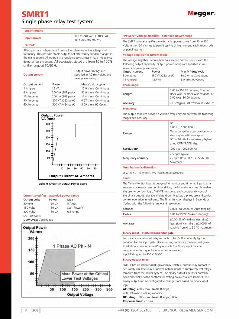
9 208 T: +44 (0) 1304 502100 E: [email protected]
SMRT1single phase relay test system
Specifications
Input power100 to 240 Volts (±10%) AC, 1ø, 50/60 Hz, 700 VA
Outputs
All outputs are independent from sudden changes in line voltage and frequency. This provides stable outputs not affected by sudden changes in the mains source. All outputs are regulated so changes in load impedance do not affect the output. All accuracies stated are from 10 to 100% of the range at 50/60 Hz.
Output currentOutput power ratings are specified in AC rms values and peak power ratings
Output current Power Max V / duty cycle1 Ampere 15 VA 15.0 V rms Continuous4 Amperes 200 VA (282 peak) 50.0 V rms Continuous15 Amperes 200 VA (282 peak) 13.4 V rms Continuous30 Amperes 200 VA (282 peak) 6.67 V rms Continuous60 Amperes 300 VA (424 peak) 5.00 V rms 90 Cycles
Current amplifier - extended power rangeOutput volts Power Max I30 Volts 150 VA 5 Amps150 Volts 150 VA See “PowerV”300 Volts 150 VA 0.5 AmpsDC 150 WattsDuty Cycle: Continuous
current Amplifier output power curve
“PowerV” voltage amplifier - extended power range
The SMRT voltage amplifier provides a flat power curve from 30 to 150 Volts in the 150 V range to permit testing of high current applications such as panel testing.
Voltage amplifier in current mode
The voltage amplifier is convertible to a second current source with the following output capability. Output power ratings are specified in rms values and peak power ratings.Output current Power Max V / duty cycle5 Amperes 150 VA (212 peak) 30.0 Vrms Continuous15 Amperes 120 VA 8.0 Vrms 90 Cycles
Phase angle
Ranges0.00 to 359.99 degrees, Counter clock wise, or clock wise rotation, or 0.00 to ±180.00 degrees
Accuracy ±0.02º typical, ±0.25º max at 50/60 Hz
Frequency
The output modules provide a variable frequency output with the following ranges and accuracy.
Ranges
DC0.001 to 1000.000 HzOutput amplifiers can provide tran-sient signals with a range ofDC to 10 kHz for transient playback using COMTRADE files.
Resolution* .0001 to 1000.000 Hz
Frequency accuracy2.5 ppm typical25 ppm 0º to 50 ºC, at 50/60 Hz Maximum
Total harmonic distortion
Less than 0.1% typical, 2% maximum at 50/60 Hz
Timer
The Timer-Monitor Input is designed to monitor and time-tag inputs, as a sequence of events recorder. In addition, the binary input controls enable the user to perform logic AND/OR functions, and conditionally control the binary output relay to simulate circuit breaker, trip, reclose and carrier control operation in real-time. The Timer function displays in Seconds or Cycles, with the following range and resolution:
Seconds 0.0001 to 99999.9 (Auto ranging)
Cycles 0.01 to 99999.9 (Auto ranging)
Accuracy±0.001% of reading, typical. ±2 least significant digit, ±0.005% of reading from 0 to 50 °C maximum
Binary input – start/stop/monitor gate
To monitor operation of relay contacts or trip SCR, continuity light is provided for the input gate. Upon sensing continuity the lamp will glow. In addition to serving as wet/dry contacts the Binary Input may be programmed to trigger binary output sequence(s). Input Rating: up to 300 V AC/DC
Binary output relay
SMRT1 has an independent, galvanically isolated, output relay contact to accurately simulate relay or power system inputs to completely test relays removed from the power system. The binary output simulates normally open / normally closed contacts for testing breaker failure schemes. The binary output can be configured to change state based on binary input logic.AC rating: 400 V max., Imax: 8 amps,2000 VA max. breaking capacityDC rating: 300 V max., Imax: 8 amps, 80 WResponse time: < 10ms

209 9WWW.mEggEr.com
SMRT1single phase relay test system
Waveform generation
Each output channel can generate a variety of output waveforms such as: DC; sine wave; sine wave with percent harmonics at various phase angles; half waves; square waves with variable duty cycles; exponential decays; periodic transient waveforms from digital fault recorders, relays with wave-form recording capability or EMTP/ATP programs, which conform to the IEEE C37.111 COMTRADE standard format.
Metering
Measured output quantities such as AC Amperes, AC Volts, DCVolts or DC Amperes, and Time may be simultaneously displayed on the large, color TFT LCD, optional STVI touch screen. The AC and DC outputs display the approximate voltage/current output prior to initiation of the outputs.
AC voltage amplitude
Accuracy±0.05% reading + 0.02% range typical, ±0.15% reading + 0.05% range maximum
Resolution .01
Measurements AC RMS
Ranges 30, 150, 300 V
AC current amplitude
Accuracy±0.05% reading + 0.02% range typical, ±0.15% reading + 0.05% range maximum
Resolution .001/.01
Measurements AC RMS
Ranges 30, 60 A
DC voltage amplitude
Accuracy0.1% range typical, 0.25% range maximum
Resolution .01
Measurements RMS
Ranges 30, 150, 300 V
DC current amplitude
Accuracy±0.05 % reading + 0.02 % range typical, ±0.15 % reading + 0.05 % range maximum
Resolution .001/.01
Measurements RMS
Ranges 30 A
Convertible source in AC current mode
Accuracy ±0.05% reading + 0.02% range typical, ±0.15% reading + 0.05% range or ±12.5 mA whichever is greater
Resolution .001
Measurements AC RMS
Ranges 5, 15 A
Environmental
Operating 0 to 50 ºC (32 to 122 ºF)
Storage -25 to 70 ºC (-13 to 158 ºF)
Relative humidity 5 - 90% RH, Non-condensing
Unit enclosures
The SMRT1 unit comes housed in a rugged, metal, lightweight enclosure. IEC Enclosure Rating IP20. Optional enclosure for 19 inch rack mount is available. Rack mount enclosure includes two BNC connectors on the back panel. These connectors are used to amplify an external analog signal using the SMRT amplifiers. Application of ±10 Volts Peak will provide Full Scale output from the selected output.
Mechanical data
Dimensions
Standard enclosure33.75W x 6H x 16.88D cm(13.5W x 2.4H x 6.75D in.)Rack mounted enclosure47.5W x 6.5H x 21.88D cm (19W x 2.6H x 8.75D in.)
Weight Standard enclosure: 4 kg (8.9 lb)Rack mounted enclosure: 4.9 kg (10.85 lb)
Safety EN 61010-1
Shock MIL-PRF-28800F (30g/11ms half-sine)
Vibration MIL-RFP-28800F (5-500 Hz, 2.05 g rms)
Transit drop MIL-RFP-28800F(10 drops, 20 cm, without transit case)(10 drops, 46 cm, with carry case)
EMC EN 61326-2-1, EN 61010-3-2/3, FCC Subpart B of Part15 Class A
Immunity EN 61000-4-2/3/4/5/6/8/11
Protection
Voltage outputs are protected from short circuits and thermally protected against prolonged overloads. Current outputs are protected against open circuits and thermally protected against prolonged overloads.
Communication interfaces
Ethernet (2)Bluetooth (optional)
Software
AVTS - STVI basic
Every unit comes with AVTS Basic software and the PC version of the STVI
Basic software packages. AVTS Basic version includes Online Vector control
(for single and multi-state timing tests), Online Ramp control (for automatic
ramping of voltage, current, phase angles or frequency) and Online
Click-On-Fault (for dynamic tests of impedance relays). Test results may be
exported directly to Microsoft Word. AVTS software includes a database for
saving test results, which can also provide the necessary information need-
ed for system reliability audits. See AVTS bulletin for more information.
The PC version of the STVI software includes the ability to bring all STVI test
data (from other STVI units) into file folders for retrieval, review and printing
whenever needed. See STVI bulletin for more information.
AVTS advanced
The AVTS Advanced version includes all the features in AVTS Basic plus
the powerful Test Editor, Dynamic Control (includes dynamic end-to-end
testing capability, and waveform recording capability), ASPEN OneLiner™
or Electrocon CAPE™ SS1 File Converter for dynamic testing, and easy to
use programming Tools for creating and editing test modules. See AVTS
bulletin for more information.

9 210 T: +44 (0) 1304 502100 E: [email protected]
SMRT1single phase relay test system
Specification continued
AVTS professional
The AVTS Professional version includes all of the features of the Basic and Advanced versions plus some other powerful test tools and features. It includes the DFR Waveform Viewer, One-Touch™ Test, Modbus communication test capability for fully automatic tests, and Waveform Digitizer to digitize scanned waveforms of electromechnical over current time curves. See AVTS bulletin for more information
oRdeRinG inFoRMATion
Model SMRT1 -
Voltage/current modules Default = 1 for a SMRT1 unit
Smart touch view interface option1 = With STVI 0 = Without
Common returns optionF = Floating Ungrounded Common ReturnC = CE mark, Floating Return
Bluetooth option1 = With Bluetooth 0 = Without
Test leads option1 = With Leads 0 = Without Leads
Enclosure optionsS = Standard field enclosure R = Rack-mount Option. Unit comes with hardware for rack mount in 19 in rack
IEC61850 option1 = With IEC 61850 GOOSE 0 = Without
Power cord optionA = North American power cord I = International power cord E = Continental Europe power cordU = United Kingdom power cord
Reserved for Future Use
1 0 n
STyle nuMbeR idenTiFicATion
deScRipTion oF SoFTwARe opTionS
included software part number
AVTS Basic with STVI application CD 81302
Software options
AVTS Basic with IEC 61850 Megger GOOSE configurator, and STVI application CD 1002-103
AVTS Advanced with STVI application CD 81570
AVTS Advanced test with IEC 61850 Megger GOOSE configurator, and STVI application CD 1001-106
AVTS Professional with STVI application CD 81571
AVTS Professional test with IEC 61850 Megger GOOSE configurator, and STVI application CD 1002-102
deScRipTionS oF HARdwARe opTionS
Voltage/current module: The SMRT1 by default the first digit will always be 1. Future: 0, Reserved for future use.Base unit options: SMRT1 does not have any base unit options. By default this digit is N for none.
Smart touch view interface option: Enter the number 1 for the unit to come with the STVI, or enter the number 0 for without.
Common returns option: The SMRT1 unit has only one option, at this time, for the return terminals associated with each output channel. It is F for floating returns.
Bluetooth option: For customers who wish to have a wireless control of the SMRT unit, enter the number 1 for the unit to come with the Bluetooth option installed. Enter 0 for without.
Power cord option: Customers can choose which type of power cord they want the unit to come with. • A Option – NEMA 5-15 to IEC 60320 C13 connectors,
UL & CSA approved for countries with NEMA outlets.• I Option - International color coded wires (light blue, brown
and green with yellow stripe) insulation jacket stripped ready
for male connector with IEC 60320 C13 connector. CE marked.
• E Option - CEE 7/7 “Schuko” plug to IEC 60320 C13 connector is CE marked.
• U Option - United Kingdom power cord with IEC 60321 C13 connector and 13 Amp fuse. CE marked.
IEC 61850 option: The SMRT1 in conjunction with the Megger GOOSE Configurator (MGC) software can be used in the testing or commissioning of IEC 61850 compliant devices. In order for the SMRT1 to be able to subscribe as well as publish GOOSE messages, the IEC 61850 feature needs to be enabled. Enter the number 1 for the unit to come with the IEC 61850 option enabled. Enter 0 for the unit without IEC 61850 enabled.
Enclosure option: The options are S for standard, and R for rack mount. Enter S, for standard, rugged metal field type enclosure. The rack unit will come in a metal enclosure with 19 inch rack mount hardware installed.
Test leads option: Enter the number 1 for the unit to come with test leads. Enter 0 for the unit without test leads.
IEC 61850 GOOSE
The SMRT with the GOOSE enabled, in conjunction with the Megger
GOOSE Configurator (MGC) software, can be used in the testing or
commissioning of IEC 61850 compliant devices. See AVTS bulletin for more
information.

211 9WWW.mEggEr.com
STVIsmart touch view interface
STVIn Large high resolution color TFT LCD touch-screen
intuitive smart navigation makes testing relays easier
n Designed for either right or left handed operation
n Automatic ramp, pulse ramp, and pulse ramp binary
search capability for pick up and dropout tests
n Overcurrent relay test includes IEC, IEEE and hundreds of
specific relay time-curves built-in
n Dynamic testing capability, multi-shot trip and
reclose ‘sequencing test screen
n Save/view/print results from internal PowerDB
ONBOARD
n Download results via USB to print
DescriptionThe Smart Touch View Interface™ (STVI) is Megger’s second
generation of handheld controllers for the new SMRT and
older MPRT1 relay test systems. The STVI, with its large, full
color, new high resolution, and high definition TFT LCD
touch screen allows the user to perform manual, steady-state
and dynamic testing quickly and easily using the manual or
sequencer test screens, as well as using built-in preset test
routines for most popular relays.
Ergonomically designed for either right or left hand operation
using the rubber cushion grips, the centrally located control
knob, and the touch screen, the STVI is extremely easy to use.
Use the new built-in stand for single-handed operation. The
STVI uses a standard ethernet cable, and power over ethernet
(POE) operation. The STVI includes non-volatile built-in data
storage for saving tests and test results. A USB port is provided
for transferring test results to your PC.
Input power
The STVI draws power through the ethernet cable using power-over-ethernet (POE) from the host unit (SMRT36), or from an external power over ethernet power supply and ethernet interface for use with SMRT1 or MPRT units.
Communication interfaces
Ethernet RJ45, 10/100 Mbits/sUSB ports: 2
Power over ethernetIEEE Std 802.3 AF
Display screenThe TFT LCD display provides high resolution, and features wide viewing angle Technology and a large screen with high luminance for reading in direct sunlight.
Dimensions128.2 H X 170.9 W mm (5.13 H X 6.84 W in), 8.4” Diagonal
Display
262 k colors, backlit, TFT LCD touch screen, anti-glare surface with hard coating, 800 Cd/m2 Luminance, 640 x 480 pixelsLanguages: English, French, Spanish and German.
Environmental
Operating 0 to 50 ºC (32 to 122 ºF)
Storage -25 to 70 ºC (-13 to 158 ºF)
Relative humidity 5 - 90% RH, non-condensing
Unit enclosure
The STVI unit comes housed in a rugged, lightweight and ergonomic plastic enclosure. It features large rubber handles, and a built in stand for hands-off operation.
Mechanical data
Dimensions275 W x 234 H x 46.8 D mm (11 W x 9.375 H x 1.875 D in.)
Weight 1.6 kg (3.6 lb)
Safety EN 61010-1
IEC enclosure rating IP30
ShockMIL-PRF-28800F (30g/11ms half-sine)
VibrationMIL-RFP-28800F (5-500 Hz, 2.05 g rms)
Transit drop MIL-PRF-28800F (46 cm, 10 impacts)
EMC
EmissionsEN 61326-2-1, EN 61000-3-2/3FCC Subpart B of Part 15 Class A
Immunity EN 61000-4-2/3/4/5/6/8/11
SPECIFICATIONS

9 212 T: +44 (0) 1304 502100 E: [email protected]
product order code
Smart Touch View Interface for SMRT36 relay test system (1 ea) STVI-1
Smart Touch View Interface for SMRT1 or MPRT relay test system (1 ea) STVI-2
Included accessories with STVI-1
Quick start guide (1 ea) 81358
STVI application software CD 81302
STVI ethernet cable assy., 210 cm (7ft.) long, (1 ea) 620094
Included accessories with STVI-2
Quick start guide (1 ea) 81358
STVI ethernet cable assy., 210 cm (7ft.) long, (1 ea) 620094
Power over ethernet power supply for SMRT1 or MPRT (1 ea) 90001-736
oRdeRinG inFoRMATion
SMRT1single phase relay test system

213 9WWW.mEggEr.com
AVTS 4.1Advanced visual test software
AVTS 4.1n Powerful, easy-to-use Microsoft® Windows® 2000/XP®/
VistaTM compatiblen Designed to manage all aspects of protective relay
testing using the SMRT or MPRT relay test setn Now loaded with more features and capabilities: n Click-on-fault n Dynamic control n Binary search n Waveform recorder n SS1 file reader n Modbus communicationsn Optional IEC 61850 test capability
DescriptionAVTS is a Microsoft Windows 2000/XP/Vista software program
designed to manage all aspects of protective relay testing
using the Megger SMRT, MPRT or older PULSAR relay test
sets. More flexibility has been added as well as some new and
powerful features.
AVTS comes in three different levels:
n Basic
n Advanced
n Professional
Every SMRT or MPRT unit comes with AVTS basic.
The Basic version includes online vector, ramp and click-on-
fault controls with the ability to import, save and execute
test modules. In addition, the basic version includes enhanced
relay test wizards, including new wizards not previously
available.
The Advanced version includes the test editor, dynamic
control, modbus, SS1 converter, end-to-end test macros
and basic programming Tools for creating and editing test
modules.
The professional version includes all of the features of the
basic and advanced versions plus some new and powerful
features. It includes the DFR waveform viewer, one-touch test,
editor, and waveform digitizer.
Online Vector Control
Click-On-Fault RIO Import of SEL 321 characteristic
Test Editor window

9 214 T: +44 (0) 1304 502100 E: [email protected]
AVTS 4.1Advanced visual test software
Feature Description Bas
ic
Ad
van
ced
Pro
fess
ion
al
Online vector controlThe Online Vector Control allows the user to have direct control of the Relay Test System. Up to sixteen vector states may be created and sequenced back through the test system. Now includes timer function for timing a given vector state.
n n n
Online ramp control
Preramp (prefault), Ramp 1 and Ramp 2 are available for use to be played back through the test system. Automatically Ramp or Pulse Ramp outputs. PulseRamp provides the capability to determine reach points on multi-zone distance relays without having to defeat the zone timing elements, and provides pre-fault load conditions for relays that require it. Enable timer control with either ramp. PulseRamp is available down to the basic level.
n n n
On-line click on fault
The user can define the type of operating characteristic using the AVTS Theoretical Control or Import files in the RIO file format, then click at a point on the characteristic that they wish to test for, either as a Shot, or using the Search features. If using the Search the test will progress down a line, using click and drag, either as a ramp or a pulse ramp looking for the relay to operate. Test results appear in the RX diagram along with the theoretical operating characteristic of the relay.
n n n
RIO file formatRIO file import allows the user to import an existing RIO file into the click-on-fault R/X diagram ready to proceed with the test. n n n
DFR playbackImport and execute relay test modules, which contain DFR playback files created using the DFR Waveform Viewer Tool. n n n
Fault calculatorCalculate fault values for Ø-Ø, Ø-N, and 3 Ø faults. Use line voltage, line Z and angle, relay volts and angle, relay amps and Z0/Z1. n n n
Import, save, and execute test modules
Import relay test files and execute selected tests. Save results to built-in Microsoft Access compatible data base, and print results. n n n
Overcurrent wizardProvides automatic testing of overcurrent relays, including pickup, timing characteristic using IEEE/ IEC formulas, Instantaneous, DC target and seal-in tests. n n n
Over/under voltage wizardProvides automatic testing of over and under voltage relays, including pickup, timing characteristic and DC target and seal-in tests. n n n
Distance wizardProvides automatic testing of distance relays. Ø-Ø, Ø-G, and 3 Phase faults are available. Test result graphics are displayed in an R X plane. n n n
Differential wizardProvides automatic testing current differential relays, including pickup, slope (includes capability to control up to 8 currents for differential characteristic), and 2nd, 3rd and 5th harmonic restraint tests on transformer differential relays.
n n n
Frequency wizard Provides automatic testing of under/over frequency relays, including pickup and timing. n n n
Transducer testing with touch-view interface or AVTS software
Use the TVI to do manual testing of all types of transducers. Results maybe saved to the internal memory, downloaded to AVTS and printed later. AVTS users may create a test for any type transducer using the Test Editor Screen and the Analog Input control tool.
i n n
Test editor Provides editing tools for modifying tests. n n
SPECIFICATIONS
iec 61850 Megger GooSe configuratorMegger GOOSE Configurator (MGC) provides easy to use
tools for testing relays and substations using the IEC 61850
protocol. It is an optional software tool available with Basic,
Advanced or Professional versions of AVTS Software. The
configurator provides relay test engineers and technicians
the capability to import parameters from configuration files
in the Substation Configuration Language (SCL) format, and/
or capture GOOSE messages directly from the substation
bus. All imported GOOSE messages will be unconfirmed
messages. Only captured messages are confirmed messages
due to the sniffing feature of the MGC. Use the MGC Merge
feature to compare imported SCL and captured GOOSE
messages to verify all GOOSE messages needed to perform
tests. Use them to configure the SMRT/MPRT to subscribe to
preselected GOOSE messages by assigning the data attributes
to the appropriate binary inputs of the SMRT/MPRT. Use the
configurator to assign the appropriate binary outputs of the
SMRT/MPRT to publish GOOSE messages simulating circuit
breaker status.

215 9WWW.mEggEr.com
AVTS 4.1Advanced visual test software
Feature Description Bas
ic
Ad
van
ced
Pro
fess
ion
al
Dynamic control
Accessed through the test editor screen, the dynamic control provides dynamic multi-state testing of relays with more flexibility and choices than vector control. A “state” can be voltage(s), current(s), phase angle(s), timers, start and stop the analog recorder, set Boolean logic for the binary inputs, set binary output(s), or even use variables to set values. The test transitions from one state to another after a programmed time delay of either milliseconds or cycles, or after a trigger condition. In addition, the dynamic control allows the user to easily build harmonic waveforms with frequencies up to 1000 Hz.
n n
Basic programming toolProvides control tool in the Test Editor. Basic programs can be written using the test system command set for special testing applications. n n
Modbus communicationsUsed in conjunction with specific Megger Test Modules to automatically download relay settings (into the AVTS setting screen) from microprocessor based relays, which use the Modbus protocol, for full automatic one-touch testing.
n n
SS1 file converterSS1 files are generated using Power System Simulation software programs by Electrocon® CAPE™ or Aspen One-liner®. By modeling the power system and using the SS1 files, the relay can then be tested dynamically using realistic system test scenarios.
n n
Import Aspen relay Database® Capability to import relay settings directly from Aspen Relay Database®. n n
End-to-end test macro“End-to-End” testing is used to describe the testing of an entire line protection scheme. This includes all protective relays, interface equipment, and any communication equipment. n n
Recorder
In association with the new dynamic control is a new recorder feature, which not only records the action of the binary inputs and outputs, but it also records the actual analogue waveforms of the MPRT voltage and current outputs. Use this new feature to capture and verify analogue output values. Use to monitor binary Inputs and outputs to capture and troubleshoot single-pole or three-pole coordination or suspected contact bounce situations. Use to capture multi-state playback to evaluate complex reclosing schemes. It will even record complex waveforms generated by the SMRT/MPRT, which could be used for harmonic evaluations.
n n
Waveform digitizerProvides digitizing tools to create digital time curves for old electromechanical relay time curves (that do not fit any time curve algorithm) up to the most complex relay operating characteristics. Good for digitizing scanned waveforms (like from a light-beam chart recorder).
n
One-Touch
Test editor control tool, used in conjunction with specific Megger test modules, to download relay settings (into the AVTS settings screen) from microprocessor based relays for full automatic one-touch testing. Used with VB script to auto test SEL relays and new MODBUS to auto test GE UR and selected Multilin relays.
n
DFR Waveform Viewer and Playback
Import, view, modify and replay digital fault recordings or EMTP/ATP simulations that are in the COMTRADE file format. n
SPECIFICATIONS
ORDERING INFORmATION
Product Order Code
AVTS basic software 5442444
AVTS basic with IEC 61850 Megger GOOSE Configurator
1002-110
AVTS advanced software 5442455
AVTS advance with IEC 61850 Megger GOOSE Configurator
1001-037
AVTS professional software 544246S
AVTS professional with IEC 61850 MeggerGOOSE Configurator
1002-038
Product Order Code
Extended software support program
1 to 2 users 10098
3 to 5 additional users 10097

9 216 T: +44 (0) 1304 502100 E: [email protected]
MGTRn Small and lightweight
n Easy to use programmable output pulse for synchronized end-to-end testing
n 100 ns accuracy within minutes of startup, 12-channel GPS timing receiver
n Near-rubidium stability during temporary GPS signal loss
DescriptionThe MGTR is a small, light-weight, field portable, GPS
satellite receiver system specifically designed to perform
end-to-end tests of line protection schemes, with Megger
SMRT, MPRT and Pulsar relay test systems. The MGTR
provides a precise Programmed Output Pulse (POP), with
100 nanoseconds of resolution. This output pulse provides
a trigger synchronization of two or more SMRT, MPRT or
Pulsar test systems to less than ±1 µ Sec of the Universal Time
Coordinated (UTC).
The unit comes with a 50 foot (15.2 m) long cable and all-
weather, high-performance, high noise immunity antenna
with an integrated low-noise preamplifier. Control of the
MGTR is through a standard RS-232 serial connection and
an adapter cable with a 9-pin D-sub connect. Software is
provided to communicate to, and control, the MGTR unit.
Input power
AC/DC adapter 90 to 265 VAC, 47-63 Hz to 24 VDC, 400 mA w/4 plug kit
Disciplined oscillatorHigh performance ovensized control (OCXO)
Long-term stability 1 x 10-12 after 24 hours tracking
Short-term stability 1 x 10-11 after 1 second tracking
Accuracy while coasting1 x 10-10 per day after 3 days of locked operation
Time to first fix (typical) Hot Start: <30 seconds (with valid almanac, time, date, position and ephemeris) Warm start: <60 seconds (with valid almanac, time, date and position) Cold start: <3 minutes typical
Programmable output pulse
Drive TTL into 50ø
Rise/Fall time 10 ns Maximum
Pulse widthProgrammable from 1 µs – 250 ms
Polarity Selectable, positive/negative
Resolution 100 ns
Accuracy 100 ns RMS
External event input TTL/CMOS level, edge-triggered, polarity selectable
Resolution 100 ns
Accuracy 100 ns RMS
MUX 1 output The output is user selectable. Outputs available are: 1, 10, 100 kHz, 1, 5, 10 MHz, 1 PPS
Drive TTL into 50ø
Rise/Fall time 10 ns Maximum
1 PPS output (Referenced to UTC)
Drive TTL into 50ø
Rise time 10 ns Maximum
Pulse widthPositive pulse, 1 ms nominal, rising edge on-time.
Accuracy 100 ns RMS
10 MHz output Standard frequency output 10 MHz. High spectral purity sinewave, +10 dBm into 50ø, ±2 dB
Temperature range (MGTR)
Operating -20 °C to 70 °C (14 °F to 158 °F)
Storage -40 °C to 85 °C (-6 °F to 185 °F)
Relative humidity (MGTR) 95% RH, Non-condensing
Dimensions
MGTR unit enclosure104.8 W x 38.1 H x 101.6 D mm (4.125 W x 1.5 H x 4.0 D in.)
MGTR unit weight 0.453 kg (1.0 lbs.)
Safety IEC 61010-1, Amendments 1 and 2
Enclosure The unit comes mounted in a rugged enclosure for field portability. An optional padded soft-sided carry case is available. The soft-sided carry case protects the unit from light rain and dust. The soft case also has pockets to hold the antenna, cables and AC/DC power supply.
MGTRGPS timing reference
ORDERING INFORmATION
Product Order Code
Megger GPS timing reference unit MGTR
MGTR Includes
Instruction manual (1 ea) 750018
MGTR receiver unit, with Software CD (1 ea.) 569010
Control cable assy. (1 ea.) 620082
GPS Antenna kit (1 ea.) 801055
Antenna kit contains the following
GPS Antenna (1 ea.) 650016
15 m 50 ft. cable (1 ea.) 620083
4 inch SS Antenna mount (1 ea.) 650017
AC/DC Power adapter (1 ea.) 561024
Optional accessories
Soft-sided transit case (1 ea.) MC6674
SPECIFICATIONS

217 9WWW.mEggEr.com
GOOSERIEC 61850 test system
GOOSER
n reliable testing of iEc 61850 relays using any conventional relay test set
n separate ethernet ports for the substation LAn and the controlling Pc forming a safe substation Bus Access Point
n seamless interaction between scL goosE and goosE “sniffing”
n goosE merge – scL goosE vs captured goosE for network troubleshooting and scD file validation at FAT
n stand alone functionality – download a configuration and run
DescriptionThe goosEr™ is the world’s first iEc 61850-8-1 goosE
test equipment, dedicated to test the goosE horizontal
communication in substation protection/control
applications.
The goosEr can convert a goosE message received
on its rear Ethernet port into binary output and it can
convert a binary input into a goosE message and publish
it at its rear ethernet port. The conversion time is typically
0.6 ms.
The goosEr is equipped with 10 binary inputs and 10
binary outputs. using these it can convert simultaneously
up to 20 goosE messages.
Binary inputs of the goosEr can react on Dc-voltage
presence (voltage sense or “wet” contact mode) or can
independently detect an applied closed/open contact
(contact sense or “dry” contact mode).
For high speed operation the binary outputs of the
goosEr are solid state, fully protected against incorrect
connections and short circuits. These have a strong
breaking capacity to drive inductive loads like auxiliary
relays.
The goosEr has two physically isolated ethernet ports:
front and rear. The goosE messages are transferred
by the firmware from the rear port to the front port,
where the messages can be visualized using the provided
Pc-goosEr software or with any third party network
analyzer. This functionality allows the goosEr to be
a secure and safe substation access point permanently
installed in the substation.
With the 6.4” color touch screen on the front panel the
goosEr can be used without the need for a Pc. The
goosEr configuration files are read from a memory stick
inserted in the usB port on the front panel.
The software Pc-goosEr provides mapping of the binary
inputs and outputs of the goosEr to the desired goosE
messages. The goosE messages are read from available
scL (substation configuration Language) files or may
be automatically detected by scanning the substation
network in search of available published goosE
messages. This process is known as goosE “sniffing”.
The Pc-goosEr also provides advanced network
trouble-shooting tasks such as comparing the goosE
messages available on the network with the goosE
messages described on the scL files with goosE mErgE
functionality; this is also a powerful tool for validating
the horizontal communication description (goosE) in the
supplied scD file at Factory Acceptance Tests (FAT) in iEc
61850 substations (consistency check).

9 218 T: +44 (0) 1304 502100 E: [email protected]
GOOSER IEC 61850 test system
Specifications GOOSERThe specifications are valid for nominal voltage supply and at an ambient temperature of +25 °C (77 °F). Specifications are subject to change without notice.EnvironmentApplication field The instrument is intended for use
in high-voltage substations and industrial environments.
Measurement category CAT I, transient voltage 1500 VTemperature, operating 0 °C to +50 °C (32 °F to +122 °F)Temperature storage & transp. -20 °C to +70 °C (-4 °F to +158 °F)Vibration IeC 60068-2 - 6Shock (non-operating) IeC 60068-2-27Humidity 5% – 95% RH, non-condensingAltitude (operational) <3000 mPollution degree 2CE markingEMC 2004/108/eCLVD 2006/95/eCGeneralMains voltage 100 – 230 V AC, 50-60 HzCurrent consumption 1 A (max)Fuses, F1 / F2 F 2ADimensions
Portable version 446 x 290 x 180 mm (17.6" x 11.4" x 7.1")
Rack mounted version 19"Weight 8.5 kg (18.7 lbs) 18.8 kg (41.4 lbs)
with accessories and transport caseUser interface 6" LCD touchscreenBINARY INPUTSNumber 10Voltage sense
Max voltage 250 V DCTransition level Approx. 15 V DC
Protection Self-protected against wrong connection
User feedback Small LeDGalvanic isolation Groupwise 3+3+2+2Contact sense
Output voltage 19 VDCShort-circuit current 15 mA
BINARY OUTPUTSNumber 10Protection Self-protected against wrong
connection. Built-in current limiterType Normally open solid state contact
Rated current range 0 – 250 mA DCRated voltage range 48 – 220 V DCBreaking capacity DC at L/R <= 40 ms
110 V DC 0.25 A
Galvanic isolation 10 separate outputsWithstand voltage 250 V DC
User feedback Small LeDCommunication portsIEC 61850 ethernet RJ-45 100 MbpsPC COM ethernet RJ-45 100 MbpsUSB MEMORY USB 2.0 type Amappable GOOSE messages to inputs/outputsBoolean (single point indication)
explicit and one level structured data set
2-bit string (double point indication)
explicit and one level structured data set
Conversion time GOOSE – Electric signalGOOSE gBinary Output 0,6 ms typicalBinary Input gGOOSE 0,5 ms typicalPublishable GOOSE messages Boolean, 2-bit String, explicit and one level structured
data set. Value according to mapped Input or default or sniffed data if not mapped.
n-bit String, Integer, Real, Time
explicit and one level structured data set. Value according to default or sniffed data
SCL file importing From IEC 61850 Edition 1 cid, scd, icd, xmlFrom IEC 61850 Edition 2 sed, iid
ORDERING INFORmATIONProduct Order Code
GOOSER Portable versionIncl. PC-GooSeR CL-19000
GOOSER Portable versionIncl. PC-GooSeR, ethernet cable 2 m (GA-00982), ethernet cable 10 m (GA-00984), USB memory stick, cable kit for GooSeR test cables (GA-00020) and soft case (GD-00215) CL-19090
GOOSER Portable versionIncl. PC-GooSeR, ethernet cable 2 m (GA-00982), ethernet cable 10 m (GA-00984), USB memory stick, cable kit for GooSeR test cables (GA-00020) and hard case (GD-00500) CL-19091
GOOSER 19” rack mounting versionIncl. PC-GooSeR CL-19005
GOOSER 19” rack mounted versionIncl. PC-GooSeR, ethernet cable 2 m (GA-00982), ethernet cable 10 m (GA-00984), USB memory stick, cable kit for GooSeR test cables (GA-00020) and hard case (GD-00500) CL-19095
Optional
PC-GOOSERWindows® software 1 to 4 licenses CL-8302e
PC-GOOSERWindows® software 5 or more licenses CL-8402e
Electrical / Fiber Optical Ethernet converter – (RJ45)/(ST) standard multimode HC-04260
Optical fiber cable, 5 m, ST-ST GA-00986
Optical fiber cable, 5 m, LC-ST GA-00987
Cable kit for GOOSER test cablesBanana plug, 2p tp black (Jumper) - 3 pcs Test cable red, 0.25 m - 10 pcs Test cable black, 1 m- 5 pcs Test cable red, 1 m - 5 pcs GA-00020
Ethernet cable, 2 m, non shielded, crossed, red GA-00982
Ethernet cable, 3 m, shielded, straight, grey GA-00985
Ethernet cable, 10 m, shielded, straight, grey GA-00984
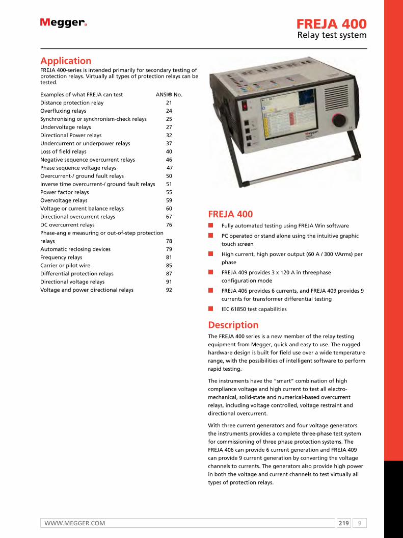
219 9WWW.mEggEr.com
FREJA 400relay test system
FREJA 400n Fully automated testing using FREJA Win software
n PC operated or stand alone using the intuitive graphic
touch screen
n High current, high power output (60 A / 300 VArms) per
phase
n FREJA 409 provides 3 x 120 A in threephase
configuration mode
n FREJA 406 provides 6 currents, and FREJA 409 provides 9
currents for transformer differential testing
n IEC 61850 test capabilities
DescriptionThe FREJA 400 series is a new member of the relay testing
equipment from Megger, quick and easy to use. The rugged
hardware design is built for field use over a wide temperature
range, with the possibilities of intelligent software to perform
rapid testing.
The instruments have the “smart” combination of high
compliance voltage and high current to test all electro-
mechanical, solid-state and numerical-based overcurrent
relays, including voltage controlled, voltage restraint and
directional overcurrent.
With three current generators and four voltage generators
the instruments provides a complete three-phase test system
for commissioning of three phase protection systems. The
FREJA 406 can provide 6 current generation and FREJA 409
can provide 9 current generation by converting the voltage
channels to currents. The generators also provide high power
in both the voltage and current channels to test virtually all
types of protection relays.
ApplicationFREJA 400-series is intended primarily for secondary testing of protection relays. Virtually all types of protection relays can be tested.
Examples of what FREJA can test ANSI® No.
Distance protection relay 21
Overfluxing relays 24
Synchronising or synchronism-check relays 25
Undervoltage relays 27
Directional Power relays 32
Undercurrent or underpower relays 37
Loss of field relays 40
Negative sequence overcurrent relays 46
Phase sequence voltage relays 47
Overcurrent-/ ground fault relays 50
Inverse time overcurrent-/ ground fault relays 51
Power factor relays 55
Overvoltage relays 59
Voltage or current balance relays 60
Directional overcurrent relays 67
DC overcurrent relays 76
Phase-angle measuring or out-of-step protection
relays 78
Automatic reclosing devices 79
Frequency relays 81
Carrier or pilot wire 85
Differential protection relays 87
Directional voltage relays 91
Voltage and power directional relays 92

9 220 T: +44 (0) 1304 502100 E: [email protected]
FREJA 400relay test system
17
16
9
10111213
2 31
56
87
4
14 15
Features and benefits1. DC supply Variable 5 to 250 V DC output at 100 W (4 A
maximum).
2. Current outputs
FReJA 403 - Up to three channels 60 A at 300 VA per phase. FReJA 406 - Up to 6 channels (3 x 60 A and 3 x 15 A). FReJA 409 - Up to 9 channels (6 x 60 A and 3 x 15 A).
3. Voltage outputs
FReJA 403/406/409 - Up to four channels 300 V at 150 VA FReJA 406/409- Three channels convertible to currents 15 A at 120 VA per phase.
4. Binary inputs 4, 5, 6, 7, 8, 9, 10. Provides seven additional monitor circuits.
5. Binary output 4 Rated for 300 V AC/DC, 8 A
6. Binary outputs 5 and 6 High speed, AC/DC voltage rating of 400 volts peak, 1 ampere.
7. Binary outputs 1, 2 and 3 Rated for 300 V AC/DC, 8 A
8. Binary inputs 1, 2 and 3 Rated 5 to 300 V AC/DC.
9. POWER ON/OFF switch Illuminates when power is on.
10. Ethernet port The primary PC connection port.
11. IEC61850 This port may also be used for connecting to the IEC 61850 substation bus for testing IEC 61850 devices.
12. USB ports Upgrade and retrive test report from local HMI.
13. SERVICE port
14. Local HmI TFT LCD , full color touch screen.
15. Dial
16. mains inlet socket 100 to 240 V, 50/60 Hz.
17. Protective earth terminal
Generator configuration
Cu
rren
t g
ener
ato
rs
Vo
ltag
e g
ener
ato
rs
Operation modes
FREJA 403 3 4 4 voltages3 currents (3 x 60 A)
4 voltages1 current (180 A)
FREJA 406 3 (6)* 4 (1)* 4 voltages3 currents (3 x 60 A)
4 voltages1 current (180 A)
1 voltage6 currents (3 x 60 A + 3 x 15 A)
FREJA 409 6 (9)* 4 (1)* 4 voltages6 currents (6 x 60 A)
4 voltages3 currents (3 x 120 A)
4 voltages2 currents (2 x 180 A)
1 voltage9 currents (6 x 60 A + 3 x 15 A)
* Three voltage channels converted to current (by configuration setting in local HMI)
221 9WWW.mEggEr.com
FREJA 400relay test system
Specifications FREJA 400-seriesSpecifications are valid for resistive load, nominal voltage supply and ambient temperature +25°C ±3°C, (77°F ±5.4°F) after 30 minutes warm up time. All hardware data are for full scale values. Specifications are subject to change without notice.
Environment
Application field For use in high-voltage substa-tions and industrial environments.
Temperature
Operating 0°C to +40°C (32°F to +104°F)
Storage & transport -25°C to +70°C (-13°F to +158°F)
Humidity 5% – 90% RH, non-condensing
Altitude (operational) 3000 m Full duty cycle up to 2000 m. Duty cycle limitation based on internal over temperature protection for altitudes >2000 m.
CE-markingEMC eN 61326:2006
LVD eN/IeC 61010-1:2001 (Second edition)
GeneralMains input 100 – 240 V AC, 50 – 60 Hz
Power consumption 2400 VA
Dimensions
Instrument 400 x 175 x 420 mm (15.7” x 6.9” x 16.5“)
Transport case 514 x 499 x 280 mm (20” x 19.7” x 11”)
Weight
Instrument (403, 406) 18 kg (39 lbs)
Instrument (409) 21 kg (46 lbs)
Transport case 10 kg (22 lbs)
Display LCD
Available languages english, French, German, Spanish,
Communication Interfaces ethernet
measurement sectionBinary inputs – Start/Stop/monitor gateTo monitor operation of relay contacts or trip SCR, continuity light is provided for the input gate. Upon sensing continuity the lamp will glow. In addition to serving as wet/dry contacts the Binary Inputs may be programmed to trigger binary output sequence(s).
Input Rating < 300 V AC / DC
TimerThe Timer-Monitor Input is designed to monitor and time-tag inputs, like a sequence of events recorder. In addition, the binary input controls enable the user to perform logic AND/oR functions, and conditionally control the binary output relay to simulate circuit breaker, trip, reclose and carrier control operation in real-time. The Timer function displays in Seconds or Cycles, with the following range and resolution:
Seconds 0.0001 to 99999.9 (Auto Rang-ing)
Cycles 0.01 to 99999.9 (Auto Ranging)
Inaccuracy
Typical ±0.001% of reading
Maximum ±2 least significant digit, ±0.005% of reading from 0 to 40°C
Binary outputsIndependent, galvanically isolated, output relay contacts to accurately simulate relay or power system inputs to completely test relays removed from the power system. The binary output simulates normally open / normally closed contacts for testing breaker failure schemes. The binary output can be configured to change state based on binary input logic.
High current output relays: Output 1,2 and 3.AC Rating (maximum values) 400 V, 8 A, 2000 VA
DC Rating (maximum values) 300 V, 8 A, 80 W
Response Time < 10ms
High speed output relaysAC/DC Rating 400 V peak, 1 A (max)
Response Time < 1 ms typical
DC supplyThe FReJA 406 includes a battery simulator with a variable DC output voltage ranging from 5 to 250 V at 100 W, 4 A max, providing capability to power up relays with redundant power supplies. Voltage output is controlled via FReJA Local
Generation sectioneach output channel can generate a variety of output waveforms such as: DC; sine wave; sine wave with percent harmonics at various phase angles; half waves; square waves with variable duty cycles; exponential decays; periodic transient waveforms from digital fault recorders, relays with waveform recording capability or eMTP/ATP programs, which conform to the CoMTRADe standard format.
ProtectionVoltage outputs are protected from short circuits and thermally protected against prolonged overloads.Current outputs are protected against open circuits and thermally protected against prolonged overloads.
meteringMeasured output quantities such as AC / DC V / A, and time may be simultaneously displayed on the large, color TFT LCD touch screen. The AC and DC outputs display the approximate voltage/current output prior to initiation of the outputs.
AC Voltage amplitudeInaccuracy ±0.05 % reading + 0.02 % range
typical, ±0.15 % reading + 0.05 % range maximum
Resolution 0.01
Measurements AC RMS
Ranges 30, 150, 300 V
AC Current amplitude
Inaccuracy ±0.05 % reading + 0.02 % range typical, ±0.15 % reading + 0.05 % range maximum
Resolution 0.001 / 0.01
Measurements AC RMS
Ranges 30, 60 A
DC Voltage amplitude
Inaccuracy 0.1% range typical, 0.25% range maximum
Resolution 0.01
Measurements RMS
Ranges 30, 150, 300 V

9 222 T: +44 (0) 1304 502100 E: [email protected]
FREJA 410relay test system
DC Current amplitudeInaccuracy
Typical ±0.05 % reading + 0.02 % range
Maximum ±0.15 % reading + 0.05 % range
Resolution 0.001 / 0.01
Measurements RMS
Ranges 30 A
Convertible source in AC Current modeInaccuracy
Typical ±0.05 % reading + 0.02 % range
Maximum ±0.15 % reading + 0.05 % range or ±12.5 mA whichever is greater
Resolution 0.001
Measurements ACrms
Ranges 5 A, 15 A
OutputsAll outputs are independent from sudden changes in mains volt-age and frequency, and are regulated so changes in load imped-ance do not affect the output. All amplifier outputs are isolated or floating.FReJA 406 with 3 convertible voltage to current generators can provide up to six current sources; three high current/high power, and three convertible channels providing lower current/high power.
Voltage outputsRange (AC) Power (VA) Current (max) Duty Cycle
30 V 150 VA 5 A Continuous
150 V 150 VA Variable* Continuous
300 V 150 VA 0.5 A Continuous
Range (DC) Power (W) Duty Cycle
0 – 300 V 150 Continuous* PowerV™ voltage amplifier output current varies depending on the voltage setting on
the 150 Volt range, see curve.
“PowerV” Voltage amplifier output power curves
PowerV™ Voltage amplifier - Extended power range
The FReJA voltage amplifier provides a flat power curve from 30 to 150 V in the 150 V range to permit testing of high current appli-cations such as panel testing.
Voltage amplifier in current mode (FREJA 406/409)The voltage amplifier is convertible to a current source with the following output capability. output power ratings are specified in rms values and peak power ratings.
Output (A) Power (VA) Voltage (max) Duty cycle5 150 (212 peak) 30.0 Vrms Continuous
15 120 8.0 Vrms 90 Cycles
Phase angleRange 0.00° to 359.99° counter clock
wise, or clock wise rotation or 0.00° to ±180.00°
Inaccuracy (at 50/60 Hz) ±0.02° typical ±0.25° max
FrequencyThe output modules provide a variable frequency output with the following ranges and accuracy.
RangesDC 0.001 to 1000.000 Hz
output amplifiers can provide transient signals with a range of DC to 10 kHz for transient playback using CoMTRADe files.
Resolution* 0.0001/0.001 Hz
Frequency inaccuracy 0° to 40°C, at 50/60 Hz
Typical 2.5 ppm Maximum 25 ppm
Total harmonic distortion at 50/60 Hz
< 0.1% typical 2% maximum
Current outputs
The per channel output current and power ratings are specified in ACrms values and peak power ratings.
Output (AC) Power (VA) Vrms (max) Duty Cycle
1 A 15 15.0 Continuous
4 A 200 (282 peak) 50.0 Continuous
15 A 200 (282 peak) 13.4 Continuous
30 A 200 (282 peak) 6.67 Continuous
60 A 300 (424 peak) 5.00 90 cycles
120 A* 600 (848 peak) 5.00 90 cycles
Output (DC) Power (VA) Duty Cycle0 – 30 A 200 W Continuous
With three currents in parallelOutput (A) Power (VA) Vrms (max) Duty Cycle12 600 (848 peak) 50.0 Continuous
45 600 (848 peak) 13.4 Continuous
90 600 (848 peak) 6.67 Continuous
180 900 (1272 peak) 5.00 90 cycles
With two currents in seriesThe compliance voltage doubles to provide 4.0 A at 100 Vrms.
Current amplifier output power curve
Current Amplifier - Extended Power Range
The FReJA current amplifier provides a unique flat power curve from 4 to 30 A per phase to permit testing of electromechanical high impedance relays, and other high burden applications, with an extended operating range up to 60 A at 300 VArms.
* 3 x 120 A only for FReJA 409
223 9WWW.mEggEr.com
Ordering informationItem Art. No.
FREJA 403 Standaloneexcl. FReJA Win, excl. soft case, excl. test leads CF-39000
FREJA 403 (with soft case)Incl. FReJA Win, soft case, test leads (GA-00033) CF-39090
FREJA 403 (with flightcase)Incl. FReJA Win, flightcase, test leads (GA-00033) CF-39091
FREJA 406 Standaloneexcl. FReJA Win, excl. soft case, excl. test leads CF-49000
FREJA 406 (with soft case)Incl. FReJA Win, soft case, test leads (GA-00033) CF-49090
FREJA 406 (with flightcase)Incl. FReJA Win, flightcase, test leads (GA-00033) CF-49091
FREJA 409 Standaloneexcl. FReJA Win, excl. soft case, excl. test leads CF-59000
FREJA 409 (with soft case)Incl. FReJA Win, soft case, 2x test leads (GA-00033) CF-59090
FREJA 409 (with flightcase)Incl. FReJA Win, flightcase, 2x test leads (GA-00033) CF-59091
Optional
FREJA WinSoftware CF-8203X
FREJA Win upgrade CF-8282X
mGCIeC 61850 Megger GooSe configuration software CF-8401X
Item Art. No.
Optional accessories
multicable GA-00105
Flight case GD-00265
Soft case GD-00315
Test lead setWith touch-proof contacts. 4 x 0.25 m (0.8 ft) / 2.5 mm2 2 x 0.5 m (1.6 ft) / 2.5 mm2 10 x 2 m (6.5 ft) / 2.5 mm2 Weight: 1 kg (2.2 lbs). GA-00033
GPS200 – mGTRThe GPS receiver GPS200 – MGTR makes it possible to synchronize two or more FReJA to conduct end-to-end testing. end-to-end testing provides quick, reliable results showing how two or more protection relay systems interact. The unit comes with a 15 m (50 ft) cable and an allweather antenna. Longer cables can be ordered. CF-90150
Cable organizerVelcro straps, 10 pcs. AA-00100
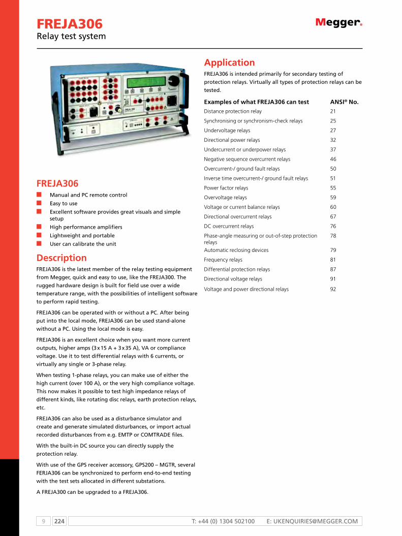
9 224 T: +44 (0) 1304 502100 E: [email protected]
FREJA306relay test system
FREJA306n manual and Pc remote control
n Easy to use
n Excellent software provides great visuals and simple setup
n High performance amplifiers
n Lightweight and portable
n user can calibrate the unit
DescriptionFrEJA306 is the latest member of the relay testing equipment
from megger, quick and easy to use, like the FrEJA300. The
rugged hardware design is built for field use over a wide
temperature range, with the possibilities of intelligent software
to perform rapid testing.
FrEJA306 can be operated with or without a Pc. After being
put into the local mode, FrEJA306 can be used stand-alone
without a Pc. using the local mode is easy.
FrEJA306 is an excellent choice when you want more current
outputs, higher amps (3 x 15 A + 3 x 35 A), VA or compliance
voltage. use it to test differential relays with 6 currents, or
virtually any single or 3-phase relay.
When testing 1-phase relays, you can make use of either the
high current (over 100 A), or the very high compliance voltage.
This now makes it possible to test high impedance relays of
different kinds, like rotating disc relays, earth protection relays,
etc.
FrEJA306 can also be used as a disturbance simulator and
create and generate simulated disturbances, or import actual
recorded disturbances from e.g. EmTP or comTrADE files.
With the built-in Dc source you can directly supply the
protection relay.
With use of the gPs receiver accessory, gPs200 – mgTr, several
FErJA306 can be synchronized to perform end-to-end testing
with the test sets allocated in different substations.
A FrEJA300 can be upgraded to a FrEJA306.
ApplicationFrEJA306 is intended primarily for secondary testing of
protection relays. Virtually all types of protection relays can be
tested.
Examples of what FREJA306 can test ANSI® No.
Distance protection relay 21
Synchronising or synchronism-check relays 25
Undervoltage relays 27
Directional power relays 32
Undercurrent or underpower relays 37
Negative sequence overcurrent relays 46
overcurrent-/ ground fault relays 50
Inverse time overcurrent-/ ground fault relays 51
Power factor relays 55
overvoltage relays 59
Voltage or current balance relays 60
Directional overcurrent relays 67
DC overcurrent relays 76
Phase-angle measuring or out-of-step protection relays
78
Automatic reclosing devices 79
Frequency relays 81
Differential protection relays 87
Directional voltage relays 91
Voltage and power directional relays 92

225 9WWW.mEggEr.com
FREJA306relay test system
Local Mode - without PCusing the dial by turning and clicking it is easy to make the
settings. All settings are saved automatically when you exit,
but if you prefer you can assign the settings a name and save
them separately for convenient access when you conduct
your next test. The display can also show the measured value
that is being generated. This feature is equivalent to three
voltmeters and three ammeters that present rms values for all
generators.
With a PC - FREJA WinThere are a number of instrument programs. You start the
different programs at the control center, where you also save
and recall results. since the test set-ups/results are saved via a
regular microsoft® Explorer display, you can create your own
test object structures.
For FrEJA Win there is no longer any license file needed and
no license keys for the FrEJA test sets. once installed on your
Pc you can freely control any FrEJA test set.
Features and benefits1. Binary inputs – response-time compensated
2. Binary outputs – operating-time compensated
3. Display and buttons used in the Local mode.
4. Dial, press to Enter.
5. Analog inputs, HigH, for volt- and ammeter
6. Analog inputs, LoW, for measurement transducers
7. Dc-supply, connect to (12) to read the values
5 6 7 8 1211109 13
1 2 3 4
Local mode General
Local mode Rx (I)
8. switch, Pc to FrEJA300/306 or relay
9. Distortion alarm
10. Voltage outputs – standard
11. current outputs – standard
12. current outputs – High-end
13. multiconnector for voltage (L1u, L2u, L3u, nu) and current
(L1i, L2i, L3i, ni).

9 226 T: +44 (0) 1304 502100 E: [email protected]
Specifications FREJA306
Specifications are valid for resistive load, nominal voltage supply and ambient temperature +25 °C ±3 °C, (77 °F ±5.4 °F) after 30 minutes warm up time. All hardware data are for full scale values. Specifications are subject to change without notice.
EnvironmentApplication field For use in high-voltage substations
and industrial environments.
Temperature
operating 0 °C to +50 °C (32 °F to +122 °F)
Storage & transport -40 °C to +70 °C (-40 °F to +158 °F)
Humidity 5% – 95% RH, non-condensing
Altitude (operational) 3000 m Full duty cycle up to 2000 m. Duty cycle limitation based on internal over temperature protection for altitudes >2000 m.
CE marking
eMC 2004/108/eC
LVD 2006/95/eC
GeneralMains input (nominal)
100 – 240 V AC, 50 – 60 Hz
Power consumption 1200 VA + 1500 VA (max)
Dimensions
Instrument 450 x 224 x 410 mm (17.7” x 8.8” x 16.1“)
Transport case 610 x 345 x 660 mm (24” x 13.6” x 26”)
Weight
Instrument 23 kg (50.7 lbs)
Transport case 12 kg (26.4 lbs)
Display LCD
Available languages english, French, German, Spanish, Swedish
measurement section
Binary inputs
Number 10 inputs (2 groups of 5 independent)
Type Dry or wet contacts 275 V DC, 240 V AC Response-time compensated
Internal resolution time 50 µs
Galvanic isolation Galvanically separated from the amplifier section. Two galvanically separated groups: 1 to 5 and 6 to 10
Max measuring time 15264 h (636 days)
Range Resolution
0 - 9.9 ms 0.1 ms
10 ms - 60 min 1 ms
1 h - 15264 h 1 s
DC current measuring input, LOWMeasuring range ±20 mA
Resolution SW 0.1 µA HW 0.6 µA
Inaccuracy 0.01% typical,0.03% guaranteed (= 6 µA)
DC voltage measuring input, LOW
Measuring range ±10 V
Resolution SW 0.1 mV HW 0.3 mV
Inaccuracy 0.01% typical,0.03% guaranteed (= 3 mV)
AC / DC current measuring input, HIGH 1)
Measuring range ±14 A DC, 10 A ACRMS
Inaccuracy DC <0.1%, AC <0.3%
AC / DC voltage measuring input, HIGH 1)
Measuring range ±220 V DC, 150 V ACRMS
Inaccuracy DC <0.05%, AC <0.2%
measurement, internally generated valuesInaccuracy
Voltage AC / DC <1% ±1 digit
Current AC / DC <2% ±2 digit
Binary outputsNumber 2 x 4 (No & NC)
Type Zero-potential contacts, controlled via software Response time compensated
Break capacity AC 240 V AC, max 8 A, max load 2000 VA
Break capacity DC 275 V DC, max 8 A, max load 240 W
Low level outputs (Rogowski option)
Setting range
LLU 3 X 0...2 VRMS
LLI 3 X 0...2 VRMS
Max. output current 5 mA
Inaccuracy <0.1% typ. (<0.2% guaranteed)
Resolution 250 μV
Distortion (THD+N) 2) <0.05% typ. (<0.1% guaranteed)
Max. generating time 5 minutes
Generator sectionVoltage outputsRange
4-phase AC 4 x 150 V
1-phase AC (L-L) 2 x 300 V
DC (L-N) 180 V
Power
3-phase AC 3 x 82 VA at 150 V
1-phase AC (L-L) 1 x 140 VA at 300 V
DC (L-N) 87 W
Resolution
SW 10 mV
HW 6.5 mV
Inaccuracy 3) (guaranteed) (±0.01% of range) + (±0.05% of reading)
Distortion (THD+N) 4) 0.02% typical (0.04% max)
FREJA306 relay test system

227 9WWW.mEggEr.com
Current outputsStandard outputs – L1I, L2I, L3I
Range
3-phase AC 3 x 15 A
1-phase AC 2) 1 x 45 A
DC (L-N) 15 A
3-channel DC –
Power
3-phase AC 3 x 87 VA
1-phase AC 2) 1 x 250 VA
DC (L-N) 3 x 87 W (max)
Resolution
SW 1 mA
HW 0.65 mA
Inaccuracy 3) (guaranteed) (±0.01% of range) + (±0.3% of reading)
Distortion (THD+N) 4) 0.1% typical (0.2% max)
High-end outputs – Ch1, Ch2, Ch3
Voltage transients - Immunity
2500 V transient level (to chassis) + working voltage level (255 V)
Working voltage 255 V Not to be used on live circuits
Application
3-phase AC (per phase)
250 VA, 5 A < I ≤ 25 A 200 VA, 25 A < I ≤ 30 A 150 VA, 30 A < I ≤ 35 A
1-phase AC (3 ch. in parallel)
750 VA, 15 A < I ≤ 75 A 600 VA, 75 A < I ≤ 90 A 450 VA, 90 A < I ≤ 100 A
3-ch. DC 3 x ±20 A
Compliance voltage ≤50 Vrms
Time limits
Continuous 3 x 20 A, 150 VA (max)
0.5 s on 1 s off repeatedly
3 x 35 A
Resolution 1.6 mA
inaccuracy5) typical < 0.3% (of reading), 0.5 A < I ≤ 35 A < 8 mA, 0 A < I ≤0.5 A
Phase inaccuracy5) < ±0.2 °
Distortion (THD+N)6) < 0.4% typical
Generators, generalFrequency range
Continuous signals DC – 2000 Hz
Transient signals DC – 3.5 kHz
Frequency resolution 1 mHz
Frequency inaccuracy 0.01%
Phase angle range 0 – 360°
Phase resolution 0.1°
Phase inaccuracy 3) ±0.1°
Connection (Amplifier outputs)
4 mm stackable safety plugs or 8-pin amplifier multiconnector
All seven generators are continuously and independently adjustable in amplitude and phase. No switching of range is necessary. All current and voltage outputs are fully overload- and short-circuit-proof and protected against external high voltage transient signals and overtemperature.
Note To allow continuous generation of high DC current (12–15 A), a minimum load impedance of 0.2 ohm is required. For lower load impedances, e.g. short-circuit, the time is limited to 1 minute.
DC auxiliary voltage outputRange 20 – 210 V DC
output power 75 W at 210 V
Otheron-line measurement of the current and voltage output, presented on the built-in display.
Calibration check when the temperature is changed. Full calibration can be conducted a any time using the FReJA calibration box. This means you do not need to send away FReJA for calibration. only the calibration box needs to be sent for calibration once per year.
Connection to IBM compatible PC (minimum Pentium II 266 MHz, 32 Mb RAM, Win 95/98/2000/XP, NT 4.0) via the serial port.
1) 50 or 60 Hz AC + harmonics only.2) THD+N: Values at 50/60 Hz, at max amplitude, 50% power and resistive load. Measurement bandwidth 22 Hz – 22 kHz.3) For sinusoidal signals at 50/60 Hz.4) Parallel connection.5) Values at max amplitude, 50% power and resistive load.6) THD+N: Values at 25 A, 125 VA.
FREJA306relay test system
9 228 T: +44 (0) 1304 502100 E: [email protected]
FREJA306relay test system
ORDERING INFORmATIONProduct Order Code
FrEJA306complete with: FrEJA Win, two test lead sets, hard transport case cF-29091
same as above but with soft transport case cF-29090
FrEJA306 basic unit cF-29001
FrEJA306, LLA rogowski option complete with: FrEJA Win, two test lead sets, hard transport case cF-29095
same as above but with soft transport case cF-29094
FrEJA306 basic unit, LLA rogowski option cF-29004
optional
FrEJA Win software cF-90090
rebuild FrEJA300 to FrEJA306 cF-90090
FrEJA Win upgrade cF-8282X
optional accessoriesFrEJA multi-cable shortens hookup time considerably. consists of a multi-pole connector that connects to FrEJA’s three voltage and three current outputs, and a number of banana plugs that connect to the protection relay that is to be tested. gA-00103
Product Order Code
Test lead set With touch-proof contacts. 2 x 0.25 m (0.8 ft) / 2.5 mm2, 2 x 0.5 m (1.6 ft) / 2.5 mm2, 8 x 2 m (6.5 ft) / 2.5 mm2. Weight: 0.8 kg (1.8 lbs). normally you need two sets. gA-00032
calibration box cF-90100
gPs200 – mgTr The gPs receiver gPs200 – mgTr makes it possible to synchronize two or more FrEJA to conduct end-to-end testing. End-to-end testing provides quick, reliable results showing how two or more protection relay systems interact. The unit comes with a 15 m (50 ft) cable and an allweather antenna. Longer cables can be ordered. cF-90150
cable organizer Velcro straps, 10 pcs. AA-00100
Floor stand FrEJA300/306 For working in standing position with FrEJA gB-00300
iPs rEFLEXiPs rELEX is a database for relay protection. For more information please visit our web site or contact customer service relay protection department.

229 9WWW.mEggEr.com
FREJA300relay test system
FREJA300n manual and Pc remote control
n Easy to use
n Excellent software provides great visuals and simple
setup
n Lightweight and portable
n user can calibrate the unit
DescriptionThe FrEJA300 relay testing system is a computer-aided relay
testing and simulation system. The weight of FrEJA300 is only
15 kg. The rugged hardware design is built for field use over
a wide temperature range, with the possibilities of intelligent
software to perform rapid testing.
FrEJA300 can be operated with or without a Pc. After being
put into the Local mode, FrEJA300 can be used stand-alone
without a Pc. using the Local mode is easy. The function of
each key is described on the display, which also presents the
settings and measured values.
The very accurate (typically 0.01%) low level analogue inputs
are designed for transducer measurements. The high level
inputs can be used as a normal volt- and ammeter. FrEJA300
can generate 4x150 V (82 VA) and 3x15 A (87 VA) or 1x45 A
(250 VA). Each output can be varied independently. Both static
and dynamic testing can be performed, such as prefault and
fault generation, simultaneous ramping of several quantities
and wave form editing.
FrEJA300 can also be used as a disturbance simulator and
create and generate simulated disturbances, or import actual
recorded disturbances from e.g. EmTP or comTrADE files.
With use of the gPs receiver accessory, gPs200 – mgTr,
several FrEJA300 can be synchronized to perform end-to-end
testing with the test sets allocated in different substations.
A FrEJA300 can be upgraded to a FrEJA306.
ApplicationFrEJA300 is intended primarily for secondary testing of
protection relays. Virtually all types of protection relays can be
tested.
Examples of what FREJA306 can test ANSI® No.
Distance protection relay 21
Synchronising or synchronism-check relays 25
Undervoltage relays 27
Directional power relays 32
Undercurrent or underpower relays 37
Negative sequence overcurrent relays 46
overcurrent-/ ground fault relays 50
Inverse time overcurrent-/ ground fault relays 51
Power factor relays 55
overvoltage relays 59
Voltage or current balance relays 60
Directional overcurrent relays 67
DC overcurrent relays 76
Phase-angle measuring or out-of-step protection relays
78
Automatic reclosing devices 79
Frequency relays 81
Differential protection relays 87
Directional voltage relays 91
Voltage and power directional relays 92

9 230 T: +44 (0) 1304 502100 E: [email protected]
FREJA300relay test system
Local Mode - without PCusing the dial by turning and clicking it is easy to make the
settings. All settings are saved automatically when you exit,
but if you prefer you can assign the settings a name and save
them separately for convenient access when you conduct
your next test. The display can also show the measured value
that is being generated. This feature is equivalent to three
voltmeters and three ammeters that present rms values for all
generators.
With a PC - FREJA WinThere are a number of instrument programs. You start the
different programs at the control center, where you also save
and recall results. since the test set-ups/results are saved via a
regular microsoft® Explorer display, you can create your own
test object structures.
For FrEJA Win there is no longer any license file needed and
no license keys for the FrEJA test sets. once installed on your
Pc you can freely control any FrEJA test set.
Local mode General
Local mode Rx (I)
Features and benefits1. Binary inputs – response-time compensated
2. Binary outputs – operating-time compensated
3. Display and buttons used in the Local mode.
4. Dial, press to enter.
5. Analog inputs, HigH, for volt- and ammeter
6. Analog inputs, LoW, for measurement transducers
7. Dc-supply, connect to (5) to read the values
8. switch, Pc to FrEJA300 or relay
9. current and voltage outputs.
10. multiconnector for voltage (L1u, L2u, L3u, nu) and current
(L1i, L2i, L3i, ni)..
5 6 7 8 10
1 2 3 4
9
231 9WWW.mEggEr.com
FREJA300relay test system
Specifications FREJA300
Specifications are valid for resistive load, nominal voltage supply and ambient temperature +25 °C ±3 °C, (77 °F ±5.4 °F) after 30 minutes warm up time. All hardware data are for full scale values. Specifications are subject to change without notice.
Environment
Application field For use in high-voltage substations and industrial environments.
Temperature
Operating 0 °C to +50 °C (32 °F to +122 °F)
Storage & transport -40 °C to +70 °C (-40 °F to +158 °F)
Humidity 5% – 95% RH, non-condensing
Altitude (operational) 3000 m Full duty cycle up to 2000 m. Duty cycle limitation based on internal over temperature protection for altitudes >2000 m.
CE marking
EMC 2004/108/eC
LVD 2006/95/eC
GeneralMains input (nominal)
100 – 240 V AC, 50 – 60 Hz
Power consumption 1200 VA (max)
Dimensions
Instrument 450 x 160 x 410 mm (17.7” x 6.3” x 16.1“)
Transport case 560 x 240 x 575 mm (22” x 9.5” x 22.6”)
Weight
Instrument 15 kg (33.1 lbs)
Transport case 7.5 kg (16.5 lbs)
Display LCD
Available languages english, French, German, Spanish, Swedish
measurement section
Binary inputs
Number 10 inputs (2 groups of 5independent)
Type Dry or wet contacts 275 V DC, 240 V AC Response-time compensated
Internal resolution time 50 µs
Galvanic isolation Galvanically separated from the amplifier section. Two galvanically separated groups: 1 to 5 and 6 to 10
Max measuring time 15264 h (636 days)
Range Resolution
0 - 9.9 ms 0.1 ms
10 ms - 60 min 1 ms
1 h - 15264 h 1 s
DC current measuring input, LOW
Measuring range ±20 mA
Resolution SW 0.1 µA HW 0.6 µA
Inaccuracy 0.01% typical,0.03% guaranteed (= 6 µA)
DC voltage measuring input, LOW
Measuring range ±10 V
Resolution SW 0.1 mV HW 0.3 mV
Inaccuracy 0.01% typical,0.03% guaranteed (= 3 mV)
AC / DC current measuring input, HIGH 1)
Measuring range ±14 A DC, 10 A ACRMS
Inaccuracy DC <0.1%, AC <0.3%
AC / DC voltage measuring input, HIGH 1)
Measuring range ±220 V DC, 150 V ACRMS
Inaccuracy DC <0.05%, AC <0.2%
measurement, internally generated valuesInaccuracy
Voltage AC / DC <1% ±1 digit
Current AC / DC <2% ±2 digit
Binary outputsNumber 2 x 4 (No & NC)
Type Zero-potential contacts, controlled via software Response time compensated
Break capacity AC 240 V AC, max 8 A, max load 2000 VA
Break capacity DC 275 V DC, max 8 A, max load 240 W
Low level outputs (Rogowski option)
Setting range
LLU 3 X 0...2 VRMS
LLI 3 X 0...2 VRMS
Max. output current 5 mA
Inaccuracy <0.1% typ. (<0.2% guaranteed)
Resolution 250 μV
Distortion (THD+N) 2) <0.05% typ. (<0.1% guaranteed)
Max. generating time 5 minutes
Generator sectionVoltage outputsRange
4-phase AC 4 x 150 V
1-phase AC (L-L) 2 x 300 V
DC (L-N) 180 V
Power
3-phase AC 3 x 82 VA at 150 V
1-phase AC (L-L) 1 x 140 VA at 300 V
DC (L-N) 87 W
Resolution
SW 10 mV
HW 6.5 mV
Inaccuracy 3) (guaranteed) (±0.01% of range) + (±0.05% of reading)
Distortion (THD+N) 4) 0.02% typical (0.04% max)

9 232 T: +44 (0) 1304 502100 E: [email protected]
3-phase AC 3 x 15 A
1-phase AC 2) 1 x 45 A
DC (L-N) 15 A
3-channel DC –
Power
3-phase AC 3 x 87 VA
1-phase AC 2) 1 x 250 VA
DC (L-N) 3 x 87 W (max)
Resolution
SW 1 mA
HW 0.65 mA
Inaccuracy 3) (guaranteed) (±0.01% of range) + (±0.3% of reading)
Distortion (THD+N) 4) 0.1% typical (0.2% max)
Generators, generalFrequency range
Continuous signals DC – 2000 Hz
Transient signals DC – 3.5 kHz
Frequency resolution 1 mHz
Frequency inaccuracy 0.01%
Phase angle range 0 – 360°
Phase resolution 0.1°
Phase inaccuracy 3) ±0.1°
Connection (Amplifier outputs)
4 mm stackable safety plugs or 8-pin amplifier multiconnector
All seven generators are continuously and independently adjustable in amplitude and phase. No switching of range is necessary. All current and voltage outputs are fully overload- and short-circuit-proof and protected against external high voltage transient signals and overtemperature.
Note To allow continuous generation of high DC current (12–15 A), a minimum load impedance of 0.2 ohm is required. For lower load impedances, e.g. short-circuit, the time is limited to 1 minute.
DC auxiliary voltage outputRange 20 – 210 V DC
output power 75 W at 210 V
Current outputsStandard outputs – L1I, L2I, L3I
Range
Otheron-line measurement of the current and voltage output, presented on the built-in display.
Calibration check when the temperature is changed. Full calibration can be conducted a any time using the FReJA calibration box. This means you do not need to send away FReJA for calibration. only the calibration box needs to be sent for calibration once per year.
Connection to IBM compatible PC (minimum Pentium II 266 MHz, 32 Mb RAM, Win 95/98/2000/XP, NT 4.0) via the serial port. 1) 50 or 60 Hz AC + harmonics only.2) THD+N: Values at 50/60 Hz, at max amplitude, 50% power and resistive load. Measurement bandwidth 22 Hz – 22 kHz.3) For sinusoidal signals at 50/60 Hz.4) Parallel connection.5) Values at max amplitude, 50% power and resistive load.6) THD+N: Values at 25 A, 125 VA.
FREJA300relay test system
FREJA300 current generators
233 9WWW.mEggEr.com
ORDERING INFORmATIONProduct Order Code
FREJA300Complete with: FReJA Win, two test lead sets, hard transport case CF-19091
Same as above but with soft transport case CF-19090
FREJA 300 basic unitIncl. FReJA Win CF-19001
FREJA 300, LLA Rogowski option Complete with: FReJA Win, two test lead sets, hard transport case CF-19095
Same as above but with soft transport case CF-19094
FREJA 300 basic unit, LLA Rogowski option CF-19004
OptionalFREJA WinSoftware CF-90090
Rebuild FREJA300 to FREJA306 CF-90090
FREJA Win upgrade CF-8282X
Optional accessories
FREJA multi-cable Shortens hookup time considerably. Consists of a multi-pole connector that connects to FReJA’s three voltage and three current outputs, and a number of banana plugs that connect to the protection relay that is to be tested.
GA-00103
Test lead set With touch-proof contacts. 2x0.25m (0.8ft)/2.5mm2 2 x 0.5 m (1.6 ft) / 2.5 mm2 8 x 2 m (6.5 ft) / 2.5 mm2 Weight: 0.8 kg (1.8 lbs). Normally you need two sets. GA-00032
Product Order Code
Calibration box CF-90100
GPS200 – mGTR The GPS receiver GPS200 – MGTR makes it possible to synchronize two or more FReJA to conduct end-to-end testing. end-to-end testing provides quick, reliable results showing how two or more protection relay systems interact. The unit comes with a 15 m (50 ft) cable and an all weather antenna. Longer cables can be ordered. CF-90150
Cable organizer Velcro straps, 10 pcs. AA-00100
AA stand FREJA300/360For working in standing position with FReJA GB-00
IPX REFLEXIPS RELEX is a database for relay protection. For more information please visit our web site or contact customer service relay protection department.
FREJA300relay test system
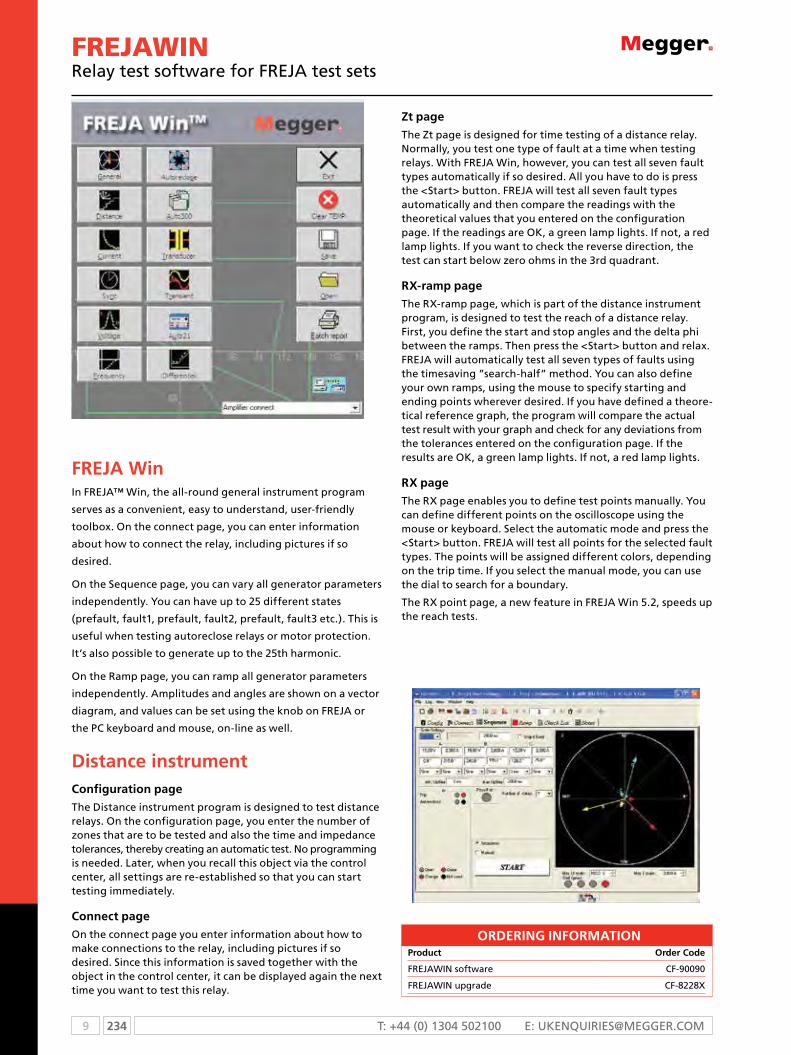
9 234 T: +44 (0) 1304 502100 E: [email protected]
FREJAWINrelay test software for FrEJA test sets
FREJA WinIn FREJA™ Win, the all-round general instrument program
serves as a convenient, easy to understand, user-friendly
toolbox. On the connect page, you can enter information
about how to connect the relay, including pictures if so
desired.
On the Sequence page, you can vary all generator parameters
independently. You can have up to 25 different states
(prefault, fault1, prefault, fault2, prefault, fault3 etc.). This is
useful when testing autoreclose relays or motor protection.
It’s also possible to generate up to the 25th harmonic.
On the Ramp page, you can ramp all generator parameters
independently. Amplitudes and angles are shown on a vector
diagram, and values can be set using the knob on FREJA or
the PC keyboard and mouse, on-line as well.
Distance instrumentConfiguration page
The Distance instrument program is designed to test distance relays. On the configuration page, you enter the number of zones that are to be tested and also the time and impedance tolerances, thereby creating an automatic test. No programming is needed. Later, when you recall this object via the control center, all settings are re-established so that you can start testing immediately.
Connect page
On the connect page you enter information about how to make connections to the relay, including pictures if so desired. Since this information is saved together with the object in the control center, it can be displayed again the next time you want to test this relay.
Zt page
The Zt page is designed for time testing of a distance relay. Normally, you test one type of fault at a time when testing relays. With FREJA Win, however, you can test all seven fault types automatically if so desired. All you have to do is press the <Start> button. FREJA will test all seven fault types automatically and then compare the readings with the theoretical values that you entered on the configuration page. If the readings are OK, a green lamp lights. If not, a red lamp lights. If you want to check the reverse direction, the test can start below zero ohms in the 3rd quadrant.
RX-ramp page
The RX-ramp page, which is part of the distance instrument program, is designed to test the reach of a distance relay. First, you define the start and stop angles and the delta phi between the ramps. Then press the <Start> button and relax. FREJA will automatically test all seven types of faults using the timesaving ”search-half” method. You can also define your own ramps, using the mouse to specify starting and ending points wherever desired. If you have defined a theore-tical reference graph, the program will compare the actual test result with your graph and check for any deviations from the tolerances entered on the configuration page. If the results are OK, a green lamp lights. If not, a red lamp lights.
RX page
The RX page enables you to define test points manually. You can define different points on the oscilloscope using the mouse or keyboard. Select the automatic mode and press the <Start> button. FREJA will test all points for the selected fault types. The points will be assigned different colors, depending on the trip time. If you select the manual mode, you can use the dial to search for a boundary.
The RX point page, a new feature in FREJA Win 5.2, speeds up the reach tests.
ORDERING INFORmATIONProduct Order Code
FREJAWIN software CF-90090
FREJAWIN upgrade CF-8228X
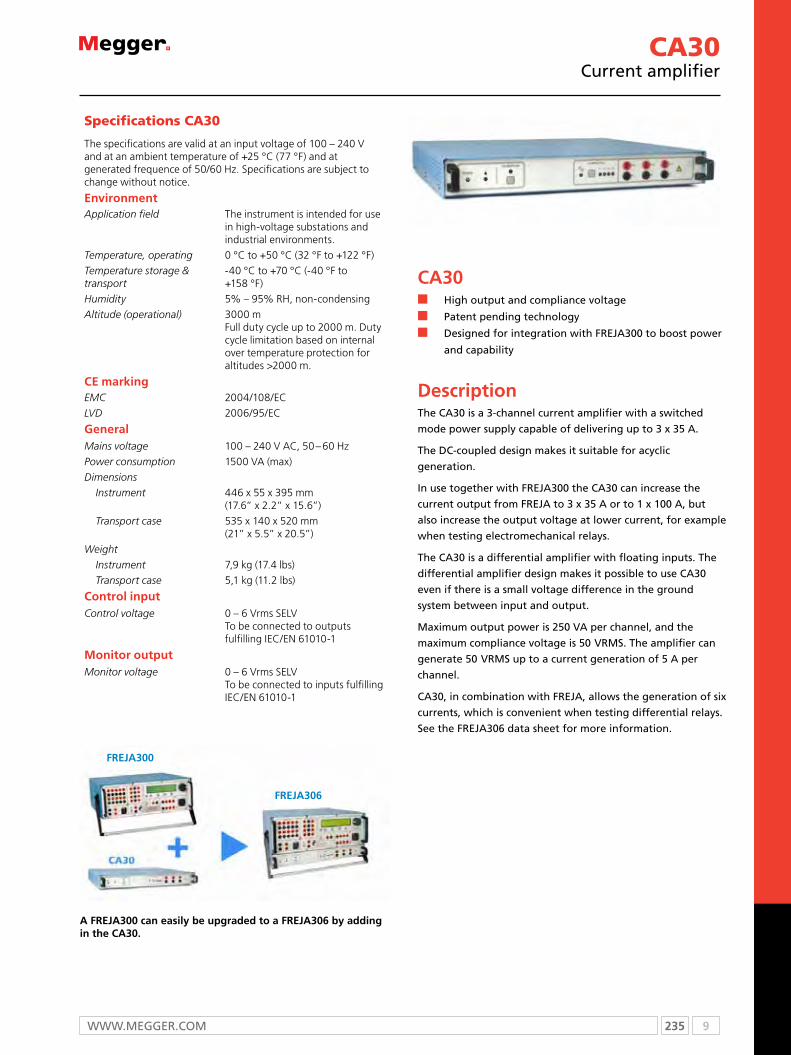
235 9WWW.mEggEr.com
CA30current amplifier
A FREJA300 can easily be upgraded to a FREJA306 by adding in the CA30.
CA30n High output and compliance voltage
n Patent pending technology
n Designed for integration with FrEJA300 to boost power
and capability
DescriptionThe cA30 is a 3-channel current amplifier with a switched
mode power supply capable of delivering up to 3 x 35 A.
The Dc-coupled design makes it suitable for acyclic
generation.
in use together with FrEJA300 the cA30 can increase the
current output from FrEJA to 3 x 35 A or to 1 x 100 A, but
also increase the output voltage at lower current, for example
when testing electromechanical relays.
The cA30 is a differential amplifier with floating inputs. The
differential amplifier design makes it possible to use cA30
even if there is a small voltage difference in the ground
system between input and output.
maximum output power is 250 VA per channel, and the
maximum compliance voltage is 50 Vrms. The amplifier can
generate 50 Vrms up to a current generation of 5 A per
channel.
cA30, in combination with FrEJA, allows the generation of six
currents, which is convenient when testing differential relays.
see the FrEJA306 data sheet for more information.
Specifications CA30
The specifications are valid at an input voltage of 100 – 240 V and at an ambient temperature of +25 °C (77 °F) and at generated frequence of 50/60 Hz. Specifications are subject to change without notice.
EnvironmentApplication field The instrument is intended for use
in high-voltage substations and industrial environments.
Temperature, operating 0 °C to +50 °C (32 °F to +122 °F)
Temperature storage & transport
-40 °C to +70 °C (-40 °F to +158 °F)
Humidity 5% – 95% RH, non-condensing
Altitude (operational) 3000 m Full duty cycle up to 2000 m. Duty cycle limitation based on internal over temperature protection for altitudes >2000 m.
CE markingEMC 2004/108/eC
LVD 2006/95/eC
GeneralMains voltage 100 – 240 V AC, 50 – 60 Hz
Power consumption 1500 VA (max)
Dimensions
Instrument 446 x 55 x 395 mm (17.6” x 2.2” x 15.6”)
Transport case 535 x 140 x 520 mm (21” x 5.5” x 20.5”)
Weight
Instrument 7,9 kg (17.4 lbs)
Transport case 5,1 kg (11.2 lbs)
Control inputControl voltage 0 – 6 Vrms SeLV
To be connected to outputs fulfilling IeC/eN 61010-1
monitor outputMonitor voltage 0 – 6 Vrms SeLV
To be connected to inputs fulfilling IeC/eN 61010-1
FREJA306
FREJA300

9 236 T: +44 (0) 1304 502100 E: [email protected]
ORDERING INFORmATIONProduct Order Code
CA30 CA-29000
CA30Including software FReJA Win and soft transport case CA-29090
CA30Including software FReJA Win and hard transport case CA-29091
Current outputsVoltage transients - Immunity
2500 V transient level (to chassis) + working voltage level (255 V)
Working voltage 255 V Not to be used on live circuits
Application
3-phase AC (per phase)
250 VA, 5 A < I ≤ 25 A 200 VA, 25 A < I ≤ 30 A 150 VA, 30 A < I ≤ 35 A
1-phase AC (3 ch. in parallel)
750 VA, 15 A < I ≤ 75 A 600 VA, 75 A < I ≤ 90 A 450 VA, 90 A < I ≤ 100 A
3-ch. DC 3 x ±20 A
Compliance voltage ≤50 Vrms
Time limits
Continuous 3 x 20 A, 150 VA (max)
0.5 s on 1 s off repeatedly 3 x 35 A
Resolution 1.7 mA
Inaccuracy1) typical < 0.3% (of reading), 0.5 A < I ≤ 35 A < 8 mA, 0 A < I ≤0.5 A
Phase accuracy error1) < ±0.2°
Distortion (THD+N)2) < 0.4% typical1) Values at max amplitude, 50% power and resistive load. 2) THD+N: Values at 25 A, 125 VA.
CA30current amplifier

237 9WWW.mEggEr.com
SVERKER750/780relay test sets
SVERKER750/780
n The engineer’s toolbox for all single phase relay testing
n Stand-alone functionality
n Rugged and reliable for field use
DescriptionThe SVERKER750/780 Relay Test Set is the engineer’s toolbox. The control panel features a logical layout, still SVERKER650 users will find it comfortably familiar and will be able to start work right away.
The SVERKER750/780 features many functions that make relay testing more efficient. For example, its powerful measurement section can display (in addition to time, voltage and current) Z, R, X, S, P, Q, phase angle and cos φ. The voltmeter can also be used as a 2nd ammeter (when testing differential relays for example). All values are presented on a single easy-to-read display.
You can also test directional protective equipment efficiently by means of the built-in variable voltage source. In SVERKER780 this has a continuous phase shift function and adjustable frequency as well. Automatic reclosing devices can also be tested – just as easily.
Designed to comply with EU standards and other personal and operational safety standards, SVERKER 750/780 is also equipped with a serial port for communication with personal computers and the PC software SVERKER Win. Since the compact SVERKER weighs only 18 kg (39 lbs), it’s easy to move from site to site.
Two or more SVERKER units can also be synchronized, which allows the user to operate a basic 3-phase test set.
ApplicationRelay TestingSVERKER750/780 is intended primarily for secondary testing of protective relay equipment. Virtually all types of single-phase protection can be tested. You can also test three-phase protection that can be tested one phase at a time, and also a number of protective relay systems that require phase shifting. Moreover, automatic reclosing devices can be tested.
SVERKER780 can test voltage relays with a frequency range from 15 Hz up tp 550 Hz.
Examples of what SVERKER can test ANSI® No.overcurrent relays 50Inverse time overcurrent relays 51Undercurrent relays 37Ground fault relays 50N, 51NDirectional overcurrent relays 67Directional ground fault relays 67Novervoltage relays 59Undervoltage relays 27Directional power relays 32Power factor relays 55Differential protection (differential circuits) 87Distance protection equipment (phase by phase) 21Negative sequence overcurrent relays 46Motor overload protection 51/66Automatic reclosing devices 79Tripping relays 94Voltage regulating relaysUnderimpedance relays 21Thermal relays 49Time-delay relays
Frequency relays (SVeRkeR780) 81
9 238 T: +44 (0) 1304 502100 E: [email protected]
SVERKER750/780relay test sets
Specifications SVERKER750 / 780
Specifications are valid at nominal input voltage and an ambient temperature of +25 °C, (77 °F). Specifications are subject to change without notice.
EnvironmentApplication field The instrument is intended for use
in high-voltage substations and industrial environments.
Temperature
Operating 0 °C to +50 °C (32 °F to +122 °F)
Storage & transport
-40 °C to +70 °C (-40 °F to +158 °F)
Humidity 5% – 95% RH, non-condensing
CE markingLVD Low Voltage Directive 2006/95/eC
EMC eMC Directive 2004/108/eC
GeneralMains voltage 115 / 230 V AC, 50 / 60 Hz
Power consumption (max) 1380 W
Protection Thermal cut-outs, automatic overload protection
Dimensions
Instrument 350 x 270 x 220 mm (13.8” x 10.6” x 8.7”)
Transport case 610 x 350 x 275 mm (24.0” x 13.8” x 10.8”)
Weight
SVERKER750 17.3 kg (38.1 lbs) 26.3 kg (58 lbs) with accessories and transport case
SVERKER780 18.1 kg (39.9 lbs) 27.1 kg (59.7 lbs) with accessories and transport case
Test lead set, with 4 mm stackable safety plugs
2 x 0.25 m (0.8 ft), 2.5 mm2
2 x 0.5 m (1.6 ft), 2.5 mm2
8 x 2.0 m (6.6 ft), 2.5 mm2
Test leads with spade tongue connectors
2 x 3.0 m (9.8 ft), 10 mm2
Display LCD
Available languages Bulgarian, Czech, english, French, German, Russian, Spanish, Swedish, Turkish
measurement section
TimerTime can be displayed in seconds or in mains-frequency cycles.
Range Resolution Inaccuracy000-9.999 s 1 ms ±(1 ms + 0.01%)*
10.00-99.99 s 10 ms ±(10 ms + 0.01 %)*
100.0-999.9 s 100 ms ±(100 ms + 0.01 %)*
* For the oFF+TIMe start condition in INT mode, 1 ms shall be added to the above measurement error.
Range Resolution Inaccuracy0.0-999.9 cycles 0.1 cycles ±(0.1 cycles + 0.01%)
1000-49999 cycles at 50 Hz1000-59999 cycles at 60 Hz
1 cycle ±(1 cycle + 0.01 %)
AmmeterMeasurement method AC, true RMS
DC, mean value
Ranges
Internal 0.00 – 250.0 A
External 0.000 – 6.000 A
InaccuracyInternal range 1)
0 – 10 A AC ±(1% + 20 mA)
0 – 40 A AC ±(1% + 40 mA)
0 – 100 A AC ±(1% + 200 mA)
External range 1)
0 – 0.6 A AC ±(1% + 20 mA)
0 – 6 A AC ±(1% + 20 mA)
0 – 0.6 A DC ±(0.5% + 2 mA)
0 – 6 A DC ±(0.5% + 20 mA)
Resolution
Internal range 10 mA (range <100 A) 100 mA (range >100 A)
External range 1 mA
VoltmeterMeasurement method AC, true RMS
DC, mean value
Range 0.00 – 600.0 V
Inaccuracy 1) AC, ±(1% + 200 mV) Max. value DC, ±(0.5% + 200 mV) Max. value Values are range depending
Extra measurementsPower factor and phase angle measurements
Range Resolution InaccuracyPower factor cos φ -0.99 (cap) to
+0.99 (ind)0.01 ±0.04
Phase angle φ (°) 000 – 359° 1° ±2°
Impedance and power measurementsAC Z (Ω and °), Z (Ω), R and X (Ω and Ω),
P (W), S (VA), Q (VAR)
DC R (Ω), P (W)
Range Up to 999 kX (X= unit)
Make / Break contact
Max. current 1 A
Max. voltage 250 V AC or 120 V DC
Reclosing test
Items measured Tripping and reclosing times
Display After test is finished a list of all times appears in display
Breaker state feedback The Make / Break contact can be used to feed back the breaker state
Max. number of reclosings 49
Max. testing time 999 s
Sets of resistors and a capacitorResistors 0.5 Ω to 2.5 kΩ
Capacitor 2) 10 μF, max voltage 450 V AC1) Measurement intervals longer than 100 ms2) SVeRkeR750

239 9WWW.mEggEr.com
Outputs
Current outputs – ACRange No-load
voltage (min)
Full-load voltage (min)
Full-load current (max)
Load / unload times On (max) / Off (min)
0 – 10 A 90 V 75 V 10 A 2 / 15 minutes
0 – 40 A 25 V 20 V 40 A 1 / 15 minutes
0 – 100 A 10 V 8 V 100 A 1 / 15 minutes
0 – 100 A 10 V - 250 A*200 A**
1 sec/ 5 minutes
* Mains voltage 230 V AC** Mains voltage 115 V AC
Voltage outputs – AC / DCRange No-load
voltage (min)
Full-load voltage (min)
Full-load current (max)
Load / unload times On (max) / Off (min)
0 – 250 V AC 290 V AC 250 V AC 3 A 10 min / 45 min
0 – 300 V DC 320 V DC 250 V DC 2 A 10 min / 45 min
Separate AC voltage source SVERKER750Range No-load
voltage (min)Full-load voltage (min)
Full-load current (max)
0 – 60 V AC 70 V 60 V 0.25 A
60 – 120 V AC 130 V 120 V 0.25 A
Both ranges are divided into voltage steps of 10 V that are steplessly variable.
Separate AC voltage source SVERKER780Range No-load
voltage (min)Full-load voltage (min)
Full-load power (max)
5 – 220 V AC minimum step 0.1 V
240 V AC 220 V AC at 33 W 200 V AC at 46 W
33 W continuously. 46 W 1 minute
Phase angle Resolution Inaccuracy0 – 359° 1° ±2°
Frequency Resolution Inaccuracy15 – 550 Hz 1 mHz ±0.1%
Auxiliary DC outputRange Voltage max. current
20 – 130 V DC 20 V DC 130 V DC
300 mA 375mA
130 – 220 DC 130 V DC 220 V DC
325 mA 400 mA
SVERKER 750/780relay test sets

9 240 T: +44 (0) 1304 502100 E: [email protected]
SVERKER750/780relay test sets
ORDERING INFORmATION
Product Order Code
SVERKER750
Incl. Test lead set GA-00030 and Transport case GD-00182 Language: English, French, German, Spanish, Swedish
115 V mains voltage CD-11190
230 V mains voltage CD-12390
SVERKER750
Incl. Test lead set GA-00030 and IP65 HD-case Language: English, French, German, Spanish, Swedish
115 V mains voltage CD-13190
230 V mains voltage CD-13390
SVERKER750
Incl. Test lead set GA-00030 and Transport case GD-00182 Language: Czech, English, German, Swedish, Turkish
230 V mains voltage CD-12392
SVERKER750
Incl. Test lead set GA-00030 and Transport case GD-00182 Language: English, French, German, Russian, Swedish
230 V mains voltage CD-12394
SVERKER750
Incl. Test lead set GA-00030 and Transport case GD-00182 Language: Bulgarian, English, French, German, Swedish
230 V mains voltage CD-12396
SVERKER780
Incl. Test lead set GA-00030 and Transport case GD-00182 Language: English, French, Spanish
115 V mains voltage CD-31190
230 V mains voltage CD-32390
Product Order Code
SVERKER780
Incl. Test lead set GA-00030 and IP65 HD-case Language: English, French, Spanish
115 V mains voltage CD-33190
230 V mains voltage CD-33390
SVERKER780
Incl. Test lead set GA-00030 and Transport case GD-00182 Language: English, German, Swedish
230 V mains voltage CD-32392
SVERKER780
Incl. Test lead set GA-00030 and Transport case GD-00182 Language: Bulgarian, English, Turkish
230 V mains voltage CD-32394
SVERKER780
Incl. Test lead set GA-00030 and Transport case GD-00182 Language: Czech, English, Russian
230 V mains voltage CD-32396
Product Order Code
Optional
SVERKER Win PC SoftwarePlease specify the SVeRkeR serial number when ordering. SVeRkeR Win contains software, a copy-protection key and cables (RS232 and USB) for connecting the PC to SVeRkeR. Note that the software key can be installed on a single SVeRkeR. The software itself, however, can be installed on an unlimited number of PCs.
CD-8102X
SVERKER Win Upgrade CD-8101X
Optional accessories
CSU20AIncl. cables and transport case
115 V mains voltage BF-41190
230 V mains voltage BF-42390
PSS750 CD-90020
Cable organizerVelcro straps, 10 pcs. AA-00100
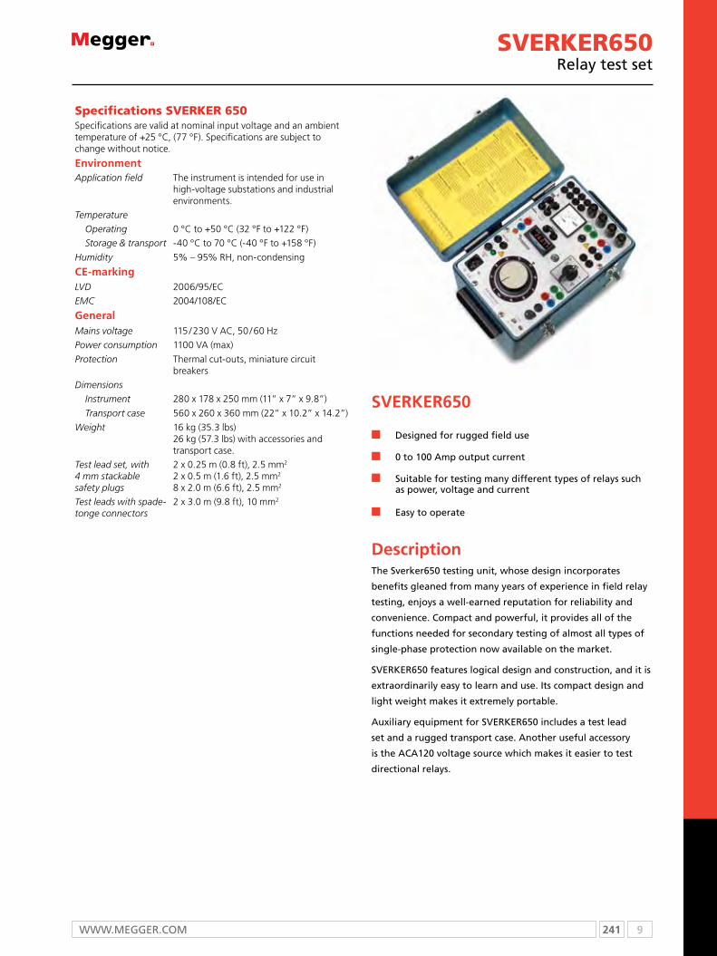
241 9WWW.mEggEr.com
SVERKER650relay test set
SVERKER650
n Designed for rugged field use
n 0 to 100 Amp output current
n Suitable for testing many different types of relays such as power, voltage and current
n Easy to operate
DescriptionThe Sverker650 testing unit, whose design incorporates
benefits gleaned from many years of experience in field relay
testing, enjoys a well-earned reputation for reliability and
convenience. Compact and powerful, it provides all of the
functions needed for secondary testing of almost all types of
single-phase protection now available on the market.
SVERKER650 features logical design and construction, and it is
extraordinarily easy to learn and use. Its compact design and
light weight makes it extremely portable.
Auxiliary equipment for SVERKER650 includes a test lead
set and a rugged transport case. Another useful accessory
is the ACA120 voltage source which makes it easier to test
directional relays.
Specifications SVERKER 650 Specifications are valid at nominal input voltage and an ambient temperature of +25 °C, (77 °F). Specifications are subject to change without notice.
EnvironmentApplication field The instrument is intended for use in
high-voltage substations and industrial environments.
Temperature
Operating 0 °C to +50 °C (32 °F to +122 °F)
Storage & transport -40 °C to 70 °C (-40 °F to +158 °F)
Humidity 5% – 95% RH, non-condensing
CE-markingLVD 2006/95/eC
EMC 2004/108/eC
GeneralMains voltage 115 / 230 V AC, 50 / 60 Hz
Power consumption 1100 VA (max)
Protection Thermal cut-outs, miniature circuit breakers
Dimensions
Instrument 280 x 178 x 250 mm (11” x 7” x 9.8”)
Transport case 560 x 260 x 360 mm (22” x 10.2” x 14.2”)
Weight 16 kg (35.3 lbs) 26 kg (57.3 lbs) with accessories and transport case.
Test lead set, with 4 mm stackable safety plugs
2 x 0.25 m (0.8 ft), 2.5 mm2
2 x 0.5 m (1.6 ft), 2.5 mm2
8 x 2.0 m (6.6 ft), 2.5 mm2
Test leads with spade-tonge connectors
2 x 3.0 m (9.8 ft), 10 mm2

9 242 T: +44 (0) 1304 502100 E: [email protected]
measurement sectionCurrent measurementBuilt-in ammeter
Ranges 0 – 10 A / 0 – 100 A
Inaccuracy ±3%
External ammeter
Output for external ammeter
Connected to built-in current transformer
Inaccuracy ±0.5%
TimerRange 0 – 999.999 s
Resolution 1 ms
Inaccuracy ±0.02% of displayed value, +2 ms Independent of mains frequency
OutputsCurrent outputs, ACRange No-load
voltage (min)
Output voltage (min)
Load / unload times On (max) / Off (min)
0 – 10 A 85 V 75 V (10 A) 2 min / 30 min
0 – 40 A 25 V 19 V (40 A) 20 s / 15 min
0 – 100 A 10 V 7.7 V (100 A) 20 s / 5 min
Voltage outputs, AC / DCRange Output voltage (min)0 – 250 V AC 220 V (2.7 A)
110 V AC (fixed) 110 V (0.3 A)
0 – 350 V DC 280 V (2 A)
20 – 220 V DC (stab.) 200 V (0.25 A)
OtherBuilt-in capacitor provides phase shift when testing directional protection, and a set of resistors can be used to divide voltages.output used to start external cycles.Terminal for external start / stop of built-in timer.Terminal for connecting serial impedance when testing nonlinear protection.
Test lead set GA-00030
ORDERING INFORmATIONProduct Order Code
SVERKER650
Incl. Test lead set GA-00030 Transport case GD-00010
115 V mains voltage BA-11190
230 V mains voltage BA-12290
Optional accessories
AcA120Variable output , 0-120 V AC BA-90040
SVERKER650relay test set

243 9WWW.mEggEr.com
Power Multimeter PMM-1multifunction measuring instrument
PMM-1 V2.12n Simultaneous measurement and display of all
three-phase system parameters
n Accurate phase angle measurement at low current levels
n Versatile, menu-driven instrument with a built-in timer and data-logging
n High-speed measurement mode
DescriptionThe Power MultiMeter (PMM-1) version 2.12 is a multifunction
instrument for measuring ac or dc voltage, ac primary and
secondary current, power, reactive power, power factor, phase
angle and frequency of a single or three-phase electrical
system.
In the single-phase mode, the PMM-1 is easily configured to
measure the amplitude and phase angle between any two
voltages and current inputs. These measured quantities are
then displayed in an enlarged font size for easier reading on a
graphic display. In three-phase mode, all measured quantities
are displayed simultaneously on a large, easy-to-read graphic
display.
The firmware in the PMM-1, combined with a built-in,
microprocessor-based timer, is specifically designed to ease
testing and commissioning of protective relay systems,
including induction unit pickup and timing tests. The PMM-1 is
a menu-driven instrument equipped with data-retention and
data-logging capabilities. It can be used to automatically store
measured data at user defined intervals from one minute to
60 minutes.
Input
Line 90 - 253 Vac, 50/60 Hz, 30 VA
Battery
Rechargeable battery with internal automatic charger. Safety features include internal battery overcharging and charge exhaustion protection.
Operation time 10 hours continuous on full charge
Voltage0 - 650 Volts (AC/DC), 0.01% resolution of range
Accuracy
± 0.05% of reading, 50/60 Hz From 3 - 650 ac Volts (21° - 25 °C).± 0.1% of reading, from 3 - 650 ac Volts (0° - 50 °C). ± 0.1% of reading ±25 mV, from 3-650 V dc.
Input impedance 1 MΩ
Maximum input1000 Volts (ac) Between inputs or from inputs to chassis.
Measured RMS or AVG
Crest factor 3
Current
Direct input0 - 100 Amperes (ac), 0.01% resolution of range
Accuracy±0.05% of reading, 50/60 Hz From 0.10 - 10 A (21°- 25 °C) ±0.1% of reading >10 amperes
Minimum current measurement 2 mA
Burden at 5A 0.1 VA
Crest factor 3
Phase angle0 - 360.00° or ±0 - 180.00°, 0.01° resolution
Accuracy 50/60 Hz
±0.08° input levels above 30 V and 1.0 amp (1), ±0.5° input levels above 3 Volts and 0.02 amps, ±2° input levels down to 0.002 amps.
Power ±0 - 100 KW, 0.1% resolution.
Accuracy at 50 or 60 Hz ±0.1% of VA.
Reactive power ±0 - 100 KVAR, 0.1% resolution.
Accuracy at 50/60 Hz ±0.1% of VA.
Frequency component only of a voltage or current
10 - 1000 Hz, 0.01 Hz resolution.
Accuracy ±0.03 Hz.
Harmonics
Measures all harmonics content simultaneously of any selected voltage or current, up to the 49th harmonic.
Accuracy ±5% of reading
Time0.000 to 999.999 seconds 0.000 to 9999.9 cycles
Seconds Mode
±LSD or ±0.005% of reading, whichever is greater when initiated by a dry contact, a DC potential above 5 volts or an AC potential above 115 VAC*.
SPECIFICATIONS

9 244 T: +44 (0) 1304 502100 E: [email protected]
Specifications continued
Cycles mode
±0.5 cycle when initiated by a dry contact, a DC potential above 5 volts or an AC potential above 115 VAC.**AC voltage accuracy is worse at lower voltages and is ±8 ms in worst cases (5 V rms applied just following wave-shape peak).
Start/stop inputs
5-300 Volts (AC or DC) start or stop inputs. AC or DC applied/removed, or dry contact closure or opening.
Voltage appliedTimer starts or stops when an AC or DC potential (5 to 300 V) is applied.
Voltage removedTimer starts or stops when an AC or DC potential (5 to 300 V) is removed.
Input resistance 1000 Ω min.
Response timeRegular measurement mode 2 readings per second.
High speed measurement mode20 readings per second for a period of 15, 30 or 60 sec.
Data input/output
RS232 serial data port
The RS232 port is provided for control of PMM-1 and transferring data from the instrument to a personal computer. PMM-1 software is included.
Printer Port
Parallel printer port is provided to allow the printing of data on an external printer. (Printer is not included with instrument.)
Dimensions13.5 H x 9 W x 9 D in. (344 W x 242 H 242 D mm)
Weight 13.4lbs (6.0 kg)
Operating temperature -15 °C to 55 °C (5 °F to 131°F)
Storage temperature -30 °C to 75 °C (-22 °F to 167 °F)
(1) Using current as reference
ORDERING INFORMATION
Product Order Code
Power multiMeter PMM-1
Included accessories
Accessory pouch
External mount portable case 17355
Fuses 1.0 A 250 V, 5 x 20 mm [2] MC7797
Line cord, three wire, 120 V 6828
Instruction manual 17357
Optional accessories
Standard potential leads [set of 4, 2m] 835312
Fused potential leads [set of 4, 2m] 830213
20-Amp current leads, states plugs [set of 3, 1m]
835313
20-Amp current leads, clips [set of 3, 1m] 835314
100-Amp current leads [set of 3, 1m] 835315
1000:1 clamp-on current transformer 830312
1000:5 clamp-on current transformer 835318
3000:1 clamp-on current transformer 835319
3000:5 clamp-on current transformer 835320
200:1 miniature clamp-on current transformer 50611
Soft carrying case 50775
Power Multimeter PMM-1multifunction measuring instrument

245 9WWW.mEggEr.com
pAM410Phase angle meter
PAM410n Designed for power system applications
n Current and voltage inputs
n Compact and lightweight
n Local calibration
n Easy to use
DescriptionThe PAM410 is specifically designed for measurements on
electrical power systems. It is capable of displaying the phase
angle relationship between two power signals, which can be
two currents, two voltages or any combination. Currents up to
25 A and voltages up to 500 V can be applied directly to the
instrument.
The current input range can be extended by using external
current transformers.
ApplicationThe PAM410 is suitable for checking polyphase metering
installations, testing protective relays, make comparative
test in electrical substations, and verifying the phase angle
deviation on power transformers.
Specifications are valid at nominal input voltage and an ambient temperature of +25 °C, (77 °F). Specifications are subject to change without notice.
EnvironmentApplication field The instrument is intended for use in
high-voltage substations and industrial environments.
Temperature
Operating 0 °C to +50 °C (32 °F to +122 °F)
Storage & transport -40 °C to +70 °C (-40 °F to +158 °F)
HumidityAltitude
5% – 95% RH, non-condensing<2000 m above sea level
CE markingEMC 2004/108/eC
LVD 2006/95/eC
GeneralMeasurement category
Enclosure classMains adapter
Adapter output voltagePower consumption
CAT III 500 VCAT IV 300 VIP21100 - 240 V AC, 50/60 Hz
9 V DC
10 W (max)
Dimensions
Instrument 260 x 140 x 55 mm (except handle) (10.2” x 5.5” x 2.2”)
Transport case 390 x 300 x 140 mm (15.4” x 11.8” x 5.5”)
Weight 1.1 kg (2.4 lbs) 3.4 kg (7.5 lbs) with accessories and transport case
Test lead set, with 4 mm stackable safety plugs
Black 2 x 2 m (6.6 ft), 2.5 mm2
Red 2 x 2 m (6.6 ft), 2.5 mm2
Display Alpha numerical LC display with back-lighter
SPECIFICATIONS
ORDERING INFORmATIONProduct Order Code
PAM410Incl. Test lead set, mains adapter and transport case BP-39090

9 246 T: +44 (0) 1304 502100 E: [email protected]
pAM420Phase angle meter
PAM420n 2 channels: voltage, current and frequency meter
n Timer
n Compact and lightweight
n Local calibration
n Rechargeable batteries
n Easy to use
DescriptionThe PAM420 is specifically designed for measurements on
electrical power systems. It is capable of displaying phase
angle, voltage, current, frequency and timing.
The phase angle is calculated from the relationship between
two power signals, which can be two currents, two voltages or
any combination.
Currents up to 25 A and voltages up to 500 V can be applied
directly to the instrument. The current input range can be
extended by using external current transformers.
ApplicationThe PAM420 is suited for checking polyphase metering
installations, testing protective relays, make comparative
test in electrical substations, and verifying the phase angle
deviation on power transformers.
Specifications are valid at nominal input voltage and an ambient temperature of +25 °C, (77 °F). Specifications are subject to change without notice.
EnvironmentApplication field The instrument is intended for use in
high-voltage substations and industrial environments.
Temperature
Operating 0 °C to +50 °C (32 °F to +122 °F)
Storage & transport -40 °C to +70 °C (-40 °F to +158 °F)
HumidityAltitude
5% – 95% RH, non-condensing<2000 m above sea level
CE markingEMC 2004/108/eC
LVD 2006/95/eC
GeneralMeasurement category
Enclosure classPower supplyMains adapter
Adapter output voltageOuput connectorPower consumption
CAT III 500 VCAT IV 300 VIP21Rechargeable batteries100 - 240 V AC, 50/60 Hz
9 V DCø5.08 mm with ø2.54 centre pin (+)
10 W (max)
Dimensions
Instrument 260 x 140 x 55 mm (except handle) (10.2” x 5.5” x 2.2”)
Transport case 390 x 300 x 140 mm (15.4” x 11.8” x 5.5”)
Weight 1.2 kg (2.6 lbs) 3.5 kg (7.7 lbs) with accessories and transport case
Test lead set, with 4 mm stackable safety plugs
Black 2 x 2 m (6.6 ft), 2.5 mm2
Red 2 x 2 m (6.6 ft), 2.5 mm2
Display Alpha numerical LC display with back-lighter
SPECIFICATIONS
ORDERING INFORmATION
ProductOrder Code
PAM410Incl. Test lead set, mains adapter (battery charger) and transport case BP-39093
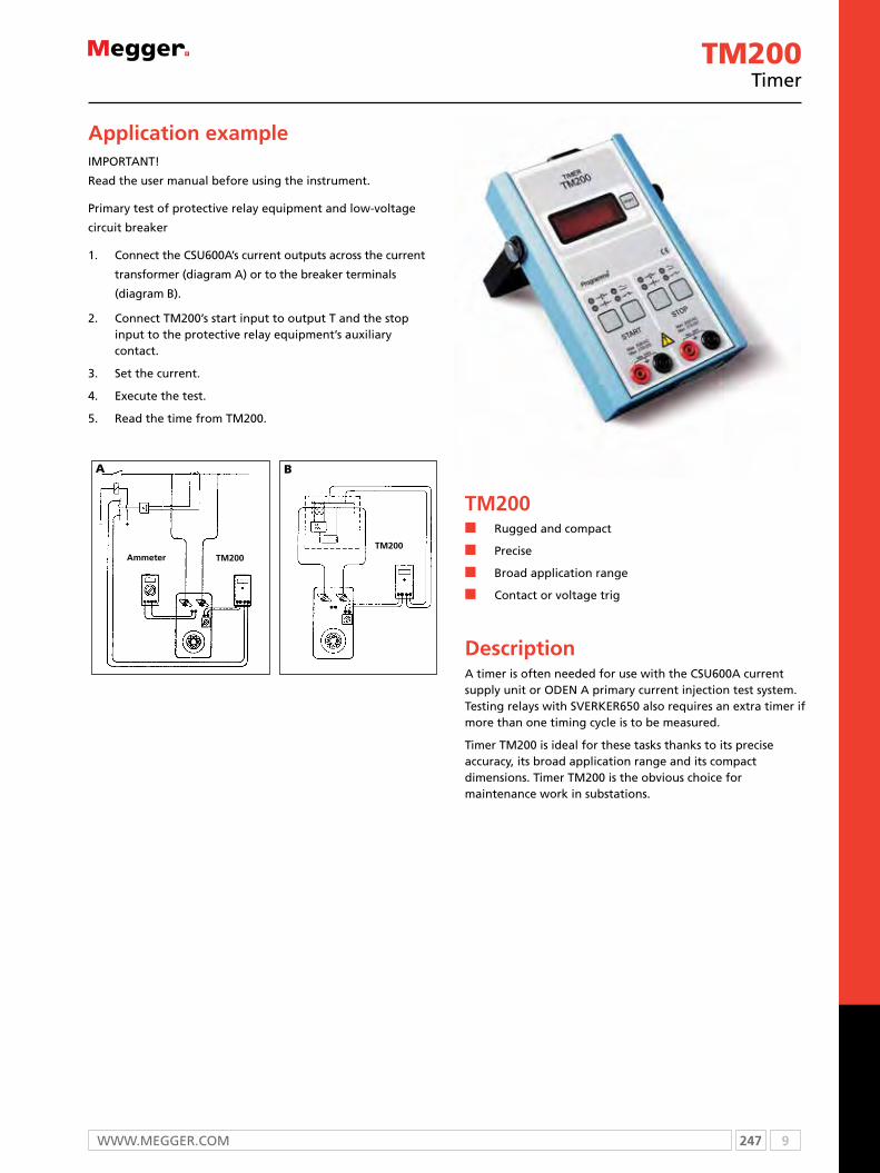
247 9WWW.mEggEr.com
TM200n Rugged and compact
n Precise
n Broad application range
n Contact or voltage trig
DescriptionA timer is often needed for use with the CSU600A current supply unit or ODEN A primary current injection test system. Testing relays with SVERKER650 also requires an extra timer if more than one timing cycle is to be measured.
Timer TM200 is ideal for these tasks thanks to its precise accuracy, its broad application range and its compact dimensions. Timer TM200 is the obvious choice for maintenance work in substations.
Application exampleimPorTAnT!
read the user manual before using the instrument.
Primary test of protective relay equipment and low-voltage
circuit breaker
1. connect the csu600A’s current outputs across the current
transformer (diagram A) or to the breaker terminals
(diagram B).
2. connect Tm200’s start input to output T and the stop input to the protective relay equipment’s auxiliary contact.
3. set the current.
4. Execute the test.
5. read the time from Tm200.
A
Ammeter Tm200Tm200
B
TM200Timer

9 248 T: +44 (0) 1304 502100 E: [email protected]
SpecificationsSpecifications are valid at nominal input voltage and an ambient temperature of +25 °C, (77 °F). Specifications are subject to change without notice.
EnvironmentApplication field The instrument is intended for use
in medium-voltage substations and industrial environments. Altitude <2000 m (6500 ft) above sea level.
Temperature
Operating 0 °C to +50 °C (32 °F to +122 °F)
Storage & transport -20 °C to +70 °C (-4 °F to +158 °F)
Humidity 5% – 95% RH, non-condensing
CE markingLVD Low Voltage Directive 73/23/ eeC
am. by 93/68/eeC
EMC eMC Directive 89/336/eeC am. by 91/263/eeC, 92/31/eeC and 93/68/eeC
GeneralMains voltage 115 / 230 V AC (switchable),
50 / 60 Hz
Power consumption (max) 20 VA
Dimensions
Instrument, excl. handle 194 x 115 x 49 mm (7.7” x 4.5” x 1.9”)
Instrument, incl. handle 252 x 132 x 49 mm (9.9” x 5.2” x 1.9”)
Weight 1.0 kg (2.2 lbs) 2.7 kg (6 lbs) with accessories and carrying case
Test lead set, with touch-proof contacts
4 x 2 m (6.6 ft), 2.5 mm²
measurement sectionRange 0-999.999 s
Resolution 1 ms
Inaccuracy ±0.02% + 1 digit of displayed value
Timer inputsMax input voltage 250 V AC / DC
Voltage modeParameter min max Unit
Threshold level, Positive at red terminal 8 20 V DC
Threshold level, Negative at red terminal -20 -8 V DC
Input current at threshold level Positive at red terminal
0.7 2.0 mA DC
Input current at threshold level Positive at black terminal
4 12 mA DC
Threshold level, low to high, 50 Hz 5 15 V ACRMS
Threshold level, high to low, 50 Hz 15 45 V ACRMS
Contact modeParameter min max Unit
Closed contact detection 0 1 kΩ
Open contact detection 4 - kΩ
Open circuit voltage 17 20 V DC
Short circuit current 8 13 mA DC
Input current at maximum input voltage, inrushParameter max Unit
At 250 V DC, Positive at red terminal 8 mA DC
At 250 V DC, Positive at black terminal 150 mA DC
At 250 V AC 80 mA DC
Input current at maximum input voltage, continuousParameter max Unit
At 250 V DC, Positive at red terminal 8 mA DC
At 250 V DC, Positive at black terminal 12 mA DC
At 250 V AC 15 mA DC
TM200Timer
ORDERING INFORmATIONProduct Order Code
TM200Incl. Test lead GA-00082 and Carrying case GD-00230 BP-29090
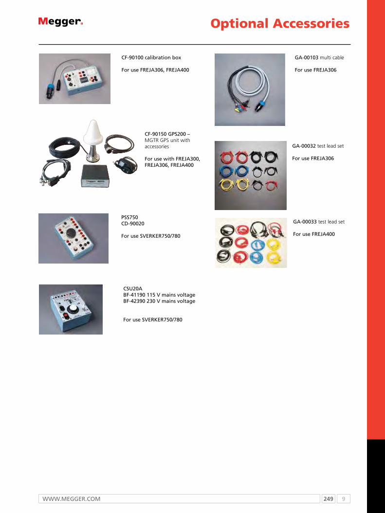
249 9WWW.mEggEr.com
gA-00103 multi cable
For use FrEJA306
cF-90150 gPs200 – MGTR GPS unit with accessories
For use with FrEJA300, FrEJA306, FrEJA400
cF-90100 calibration box
For use FrEJA306, FrEJA400
gA-00032 test lead set
For use FrEJA306
optional Accessories
csu20A BF-41190 115 V mains voltageBF-42390 230 V mains voltage
For use sVErkEr750/780
Pss750cD-90020
For use sVErkEr750/780
gA-00033 test lead set
For use FrEJA400

9 250 T: +44 (0) 1304 502100 E: [email protected]
optional Accessoriesfor pMM1
Standard potential leads835312 The standard potential leads are for general use when measuring a standard voltage system.Set of 4 leads, 2 m (6 ft. 6 in.)
20 Amp States current plug835313 The measurement of secondary current from a distribution test switch can be obtained by using the 20 amp states current plug.Set of 3 states current plugs, 1 m (3 ft. 6 in.)
Fused potential leads830213 The fused potential leads provides the technician protection when measuring a higher system voltage (600 vac/2 amp fuse).Set of 4 fused leads, 2 m (6 ft. 6 in.)
Miniature Clamp-On CT50611 The miniature clamp-on CT makes it easy to check current path in a wired distribution panel without worry of interrupting a current circuit in service.
Ratio: 200:1
Accuracy Class: ±1%
Cable Size: 0.59 in. (14.98 mm)
Dimensions:96.5 H x 43 W x 23 D mm(3.8 H x 1.69 W x 0.9 D in.)
Weight: 0.11 Kg (0.25 lbs)
Clamp-On CT 1000830312 835318
Ratio: 1000:1 (Cat. No. 830312) 1000:5 (Cat. No. 835318)
Accuracy Class:±1%
Cable Opening:43.18 mm (1.7 in.) (US) 51 mm (2.0 in.) (NS)
Busbar Opening:43.18 mm x 11.94 mm (1.7 in. x 0.47 in.) (US)
Dimensions:203 H x 63.5 W x 40.6 D mm(8.0 H x 2.5 W x 1.6 D in. )
Weight:0.55 Kg (1.2 lbs)
Soft Carrying case50775 Padded Canvas/polyester case
Dimensions:281.0 H x 255 W x 255 D mm (11.0 H x 10.0 W x 10.0 D in.)
Weight:0.37 Kg (0.8 lb)
Clamp-On CT 3000835319835320
Ratio: 3000:1(Cat. No. 835319) 3000:5 (Cat. No. 835320)
Accuracy Class: ±1%
Cable Opening: 70 mm (2.76 in.)
Busbar Opening: 127 mm x 33 mm or 102 mm x 45.7 mm (5.0 in. x 1.3 in. or 4.0 in x 1.8 in. )
Dimensions: 144.8 H x 335.3 W x 51 D mm(5.7 H x 13.2 W x 2.0 D in. )
Weight: 1.7 Kg (3.7 lbs)

251 9WWW.mEggEr.com
SMRT optional Accessories
2001-487Accessory carry case for STVI, SMRT1 and SMRT400 test leads.
2001-394Sleeved pair of test leads.
684004Cable / spade lug adaptor (small, red)
684005Cable / spade lug adaptor (small, black).
2001-573Jumper lead for SMRT1 and SMRT36, SMRT400
620143Individual red (non-sleeved) test leads.
620144Individual black (non-sleeved) test lead for SMRT1.
684002Cable / spade red lug adaptor (large).
684003Cable / spade black lug adaptor (large).
684006Alligator / crocodile red clip.
684007Alligator / crocodile black clip.
2001-396Sleeved combination current test leads.
2001-395Sleeved combination voltage test lead for SMRT36, SMRT400
1001-632Rugged hard sided transit case for SMRT36.
2002-468Rugged hard sided transit case for SMRT1.

9 252 T: +44 (0) 1304 502100 E: [email protected]
81571AVTS Professional relay test software with STVI application.
MGC IEC61850 GOOSEconfiguration software for SMRT
90001-845Flexible test lead adaptor
90001-843Flexible test lead adaptor with retractable insulated sleeve - red
9001-844Flexible test lead adaptor with retractable insulated sleeve - black
SMRT optional Accessories
568026In-line fused test lead - blue.
568025In-line fused test lead for SMRT1 - black.
500395In-line resistor test lead - red.
FTP10Test paddle for SMRT1.
TPA10STATES® 10 pole test paddle attachment.

253 9WWW.mEggEr.com

10 254 T: + 44 (0) 1304 502100 E: [email protected]
Selection guide ......................................................................................... 255Technical information ................................................................................ 256OTS80PB/OTS60PB portable oil test set ..................................................... 258OTS100/80/60AF series laboratory oil test sets .......................................... 261VCM100/VCM80D oil test set calibration meter ........................................ 264KF875 and KF-LAB MkII Karl Fischer moisture in oil test sets ...................... 265 MTO210 transformer ohmmeter ............................................................... 266MTO300 transformer ohmmeters .............................................................. 269TTR25 handheld transformer turns ratio .................................................... 271TTR100 handheld transformer turns ratio .................................................. 274TTR300 three-phase transformer turns ratio test sets ................................. 258FRAX series sweep frequency response analyzers....................................... 277MCT1605 multi-tap automatic current transformer saturation, ratio and polarity tests set ................................................................................. 284 MAGNUS step-up transformer .................................................................. 286 PowerDB ................................................................................................... 288
Transformers maintenance has seen a move toward reliability and condition based maintenance schedules.
To assist and support transformer owners and manufacturers Megger has invested in providing the latest test and diagnostic equipment to ensure your assets’ health is kept in check.
Transformer Tests
10

255 10WWW.mEggER.com
SELECTION GUIDE
Do you need... 12 kV insulation diagnostic system or a insulation diagnostic analyzer?
See the DELTA400 on page 40 and IDAX testers on page 36
Component Test Delta IDAX MIT FRAX MLR TTR MTO CBA MOM OTS KF
Windings
Resistance n
Ratio/polarity n
Excitation current n n n
Short circuit impedance n n
Frequency response analysis n
Insulation resistance n
Capacitance n n
Power factor/tan delta n n
Dielectric frequency response
n
Bushings
Capacitance n n
Power factor/tan delta n n
Dielectric frequency response
n
Insulating oil
Water content n
Dielectric strength n
Power factor/tan delta n n
Cellulose insulation Moisture content n
Tap changers
Load
Resistance n
Ratio n
Continuity (make before break) n
Dynamic resistance (DRM) n
De-energised
Resistance n
Ratio n
Core/tank
Insulation resistance n
Frequency response analysis n
Ground test n

10 256 T: + 44 (0) 1304 502100 E: [email protected]
Transformer testing
Power transformers in industrial premises - are you covered?
It’s easy to assume that the substation on your site belongs to the
power utility, but are you absolutely sure? If you get it wrong, and
you’re unlucky enough to suffer a transformer fault, you could find
yourself landed with a massive repair bill.
In the substation, the power transformers are probably the most
expensive items. And that’s not the worst of it. The delivery time
for a replacement transformer is typically months, or even years for
the largest types. The direct and indirect costs associated with a
transformer failure can therefore be enormous.
But there’s surely no need for concern. All of the power
transformers on your site are the responsibility of your energy
supplier, aren’t they? It may be a very good idea to check again.
In a surprisingly large percentage of installations, the power
transformers belong to the owner of the premises, and not to the
power utility.
Of course there’s still no reason to worry, because transformer
failures will certainly be covered by insurance, won’t they? The
answer is possibly not. Because of the huge costs involved, insurers
are understandably cautious about making payouts relating to
transformer faults and failures. If there is a claim, they will certainly
ask for evidence to show that the transformer has been regularly
tested and maintained.
Since many companies are not even aware that they are responsible
for the power transformers on their sites, it’s not too much of a
surprise that there are a lot of transformers that most certainly don’t
get the regular attention they need.
This is a special concern with the many transformers currently in
use that have long exceeded their design lives. Although they may
apparently still be working well, it is inevitable that some of the
materials used in their construction – in particular the insulating
materials – will have started to deteriorate.
If an unmaintained transformer fails, whether it is old or new, it’s
perfectly possible that the insurers will contest the claim or refuse
to pay. Let’s take a look at what needs to be done to avoid this
potentially devastating situation.
The first and most obvious step is for maintenance departments to
check which of the transformers on their site are their responsibility.
The next step is to implement a regular testing programme for these
transformers.
But what form should the testing take? There are of course
many types of conventional tests that can be applied to power
transformers to check; for instance, the performance of the tap
changers or the windings.
This means that to build up a reasonably complete picture of the
transformer’s condition, a whole battery of tests is needed, which
will take a considerable time to perform. During this time, the
transformer will necessarily be out of service, which can be very
inconvenient.
There are, however, two tests that between them can provide
a wealth of information, not only about the presence of faults
but also in many cases their type and location. These tests are
sweep frequency response analysis (SFRA) and frequency domain
spectroscopy (FDS).
Electrically, a transformer is made up of multiple capacitances,
inductances and resistances. It is in effect a very complex circuit
that produces a unique “fingerprint” when test signals are injected
over a range of frequencies and the results plotted as a curve. In
particular the distance between conductors affects the capacitances
in the transformer.
Movement of the windings, which can be caused by electrical
overloads, mechanical shocks or simply by ageing will therefore alter
the capacitances and change the shape of the frequency response
curve.
The SFRA test technique for transformers is based on comparisons
between measured curves which allow variations to be detected.
An SFRA test involves multiple sweeps and reveals whether the
mechanical or electrical integrity of the transformer has been
compromised.
SFRA tests are used to capture a “fingerprint” reference curve for
each winding when the transformer is new or when it is known to
be in good condition. These curves are subsequently used as the
basis for comparisons during maintenance or when problems are
suspected.
The best way to use SFRA testing is to take regular measurements
on the same transformer over a period time, and to compare the
results. However it is also possible to use type-based comparisons
between transformers with the same design. Finally, a construction-
based comparison can be used in some circumstances, when
comparing measurements between windings in the same
transformer.
A single SFRA test can detect winding problems that would
otherwise require multiple tests with various kinds of test

257 10WWW.mEggER.com
equipment, as well as problems that cannot be detected at all by
tests of other kinds.
As a general guide, magnetisation and other problems relating to
the core alter the shape of the SFRA curve at the lowest frequencies,
up to around 10 kHz. Medium frequencies, from 10 kHz to 100 kHz
represent axial or radial movements in the windings, and high
frequencies above 100 kHz correspond to problems involving the
cables from the windings to bushings and tap changers. In modern
SFRA test sets, built-in analytical tools simplify comparisons between
curves.
While SFRA tests provide a lot of information about the condition
of a transformer, they do not give an accurate indication of the
presence of contaminants – in particular water – in the transformer
insulation. Standard tests, such as the widely used Karl Fischer test
are of course available for accurately assessing the moisture content
of transformer oil, but this is not the whole story.
In fact, it is usual for a much greater percentage of the moisture in
a transformer to be held in solid insulation such as paper than is
held in the oil. To further complicate matters, the moisture moves
between the solid insulants and the oil in a way that is influenced by
many factors including, in particular, temperature.
Measuring the moisture content of the oil many not therefore
provide dependable information about the moisture content of the
transformer’s solid insulation. This is a serious concern, as moisture
in the insulation significantly accelerates the ageing process in
transformers and it can cause bubbles between windings that lead
to sudden catastrophic failures.
To establish the moisture content in the transformer, the second of
the tests mentioned earlier – frequency domain spectroscopy (FDS) –
could be used. Initially, this may sound a lot like SFRA, as it involves
measuring transformer characteristics over a range of frequencies.
This time, however, it’s the dielectric properties of the insulation
(capacitance, loss and power factor) that are measured over a range
of frequencies, typically from one millihertz to one kilohertz.
These are, in essence, the same dielectric tests that are often carried
out at power frequency, but testing at a single frequency provides
far less information than is revealed by FDS testing. Unlike spot-
frequency testing, FDS can for example reliably distinguish between
a transformer that is dry but has bad oil and one that is wet but has
good oil. In the first case, the oil needs refurbishing or replacing; in
the second the transformer only needs drying out.
FDS testing also has other benefits – it can be performed at any
temperature, and the test can be completed quickly. Software can
be used to calculate the water content in percentage terms, and
modern FDS test sets typically provide accurate and detailed results
in less than 20 minutes.
Regular testing using the SFRA and FDS test techniques provides a
reliable insight into the condition of power transformers, but how
can this information best be used by the transformer owner?
A short-circuit fault on the transformer may cause unseen damage
inside, and a damaged transformer put back into service could fail
catastrophically. An SFRA test can be done before re-energising and
compared to a reference trace taken while the transformer was in
good working order. If the two traces match, nothing has changed
and the transformer can be safely returned to service. Carrying out
this test takes less than an hour, reducing outage time and saving
money.
Ageing, mechanical damage and moisture content can be seen as a
change in the frequency response of the transformer over time and
may indicate that remedial action such as drying out the transformer
is needed to guard against future failures. In other cases, it may
show that the transformer is inevitably coming to the end of its
useful life, but even then the information is invaluable.
In this situation, it may be possible to minimise the load on the
transformer so that it can continue in service until a replacement
is obtained. Even in the worst case, there is at least a warning that
failure is imminent, which can allow time for contingency plans to
be made and put into place.
There is another very valuable aspect of regular testing, which we
touched on earlier. Insurance companies are more likely to honour a
claim for failure of a power transformer that’s been regularly tested
and properly maintained so as to remedy any issues identified by the
tests. Such a transformer is, of course, less likely to fail, but if it does
there is at least the consolation that the insurers might foot the bill!
Even for those who are aware of their responsibilities in looking
after power transformers, regular testing may appear as something
of a burden. However, tests with modern instruments can be
performed quickly and easily, and they yield dependable informative
results. And, if the test regime eliminates just one unforeseen
transformer failure that would otherwise have occurred, the effort
involved in testing and the cost of the instruments used will have
been repaid many times over.

10 258 T: + 44 (0) 1304 502100 E: [email protected]
OTS80PB and OTS60PBPortable oil test sets
SPECIFICATIONS
OTS80PB and OTS60PBn Light-weight, rugged, portable instruments for
measuring insulating oil breakdown voltage
n Lock in precision - oil vessel with lockable adjustment
n Bright 3.5 inch colour display visible out-doors
n Suitable for mineral, ester and silicon oils
n Trip detection circuit with direct measurement of voltage and current
n Ultra fast (<10 µs) HV switch off time
DescriptionAutomatic portable oil test sets perform accurate breakdown voltage tests on mineral, ester and silicon insulating liquids. moulded test vessels give repeatable results in the field and laboratory with lock in precision electrode gap setting adjustment wheels. The transparent, shielded lid is a key feature enabling users to see what is happening within the test chamber.
The portable 60 kV and 80 kV oil test sets are very light ranging from 16 kg to 23.5 kg depending on model and configuration. They come complete with optional carry bag and transport case. The carry bag has pouches for electrode accessory pack, leads, quick user guide, paper roll etc.
Applicationsmonitoring and maintenance of oil quality is essential in ensuring the reliable operation of oil filled electrical equipment. codes of practice have been established in many countries that include several different types of test on insulating oils.
one of the fundamental tests of oil quality is the breakdown voltage test, which is a measure of the oil’s ability to with-stand electric stress. A low breakdown voltage can indicate the presence of contaminants such as water or conductive particles.
Test voltage
oTS60PB -30 to +30 kVrms
oTS80PB -40 to +40 kVrms
Voltage resolution 0.1 kV, ±1%, ±2 digits
Programmed test sequences
See page 250
Languages supported
English, French, German, Spanish, Czech, Dutch, Finnish, Italian, Norwegian, Polish, Portuguese, Russian and Swedish.
Vessels 400 ml (standard) 150 ml (option)
The test vessel provides precision electrode alignment and adjustment wheels lock electrodes in position, option of 150 ml vessel for low volume oil samples
Temperature sensor resolution
1 ºC
Power supply
Line voltage 85 to 265 VACLine frequency 50/60 Hz
oTS80PB onlyBatteries (option)
Lead acid 2 x 12 V 4 Ah, or NiMH 24 V 2 AH
OTS80PB only Interfaces
USB 2.0 compatible2 x USB type-A (memory stick)1 x USB type-B (printer or PC)
Printer
Internal printer (option)Matrix impact printerPaper 57.5 mm wide
External printerAny printer with USB interface and PCL3 driver
Protection Safety interlock on cover
Display320 x 240 QVGA colour display with backlight
Environmental
operating temperature 0 ºC to +50 ºC
Storage temperature -30 ºC to +65 ºC
Humidity80% RH at 40 ºC operation95% RH at 40 ºC storage
Safety
Designed in accordance with IEC 61010
EMCLight industrial IEC 61326-1 Class B, CISPR 16-1 and CISPR 16-2
Mechancial data
Dimensions (W x H x D
oTS60PB 520 mm x 340 mm x 250 mm
oTS80PB 520 mm x 380 mm x 250 mm
Weight
oTS60PB16 kg (printer, no battery)16.8 kg (printer, NiMH battery)
oTS80PB20 kg (printer, no battery)20.8 kg (printer, NiMH battery)23.2 kg (printer, lead acid batteries)
Test vessels 1.1 kg (400 ml and 150 ml)
SPECIFICATIONS

259 10WWW.mEggER.com
ORDERING CONFIGURATIONExample of an ordering configuration:-OTS80PB-EU2-EP-4C = This order is for an OTS80PB with EU power lead, NiMH battery, IEC electrode set,
internal printer, lid stirrer and carry bag.
Model: OTS PB- - -Weights
80 kV 80 19.4 kg
Select model
60 kV 60 15.3 kg
EU lead EU
UK lead UKSelect powercord
US lead US
Australian AUlead
No Plug BLlead
Sealedlead 1 3.3 kgacid OTS80PB
ONLYSelectbattery NiMH 2 0.8 kgoption
No X 0 kgbattery
ASTM Aset
Selectelectrode IEC set E
set
Full set U
Internal P 0.54 kgSelect printerprinteroption
No printer X 0.08 kg
Stirrer lid 4 0.3 kgSelect assemblystirrer fittedoption
Stirrer lid Xassemblynot fitted
Carry C 1.3 kgcase
Select carry case
option No carry Xcase
NONE
OTS80PB and OTS60PBPortable oil test sets
10 260 T: + 44 (0) 1304 502100 E: [email protected]
OTS80PB and OTS60PBPortable oil test sets
ORDERING INFORMATION
Product Order Code
oTS60 PB configured*
oTS80PB configured*
Included accessories
Vessel 400 ml assembly
12 V vehicle charger lead (supplied only on instruments configured with a battery)
magnetic bead stirrers (2 off)
magnetic bead retriever
Feeler gauge set 1, 2, 2.5, 2.54 mm
User manual
configured accessories (to order additional or spares)
IEc60156 electrode set - 12.7 mm spherical (2), 36 mm mushroom (2)
1001-477
ASTm D877/1816 electrode set - 25.4 mm cylindrical (2 standard, and 2 none standard, 36 mm mushroom (2)
1001-478
Full electrode set ASTm and IEc electrodes 1001-479
Vessel lid mounted impeller (ASTm D1816) for use with 400 ml vessel
1001-102
carry bag (padded) oTS80PB 1001-476
carry bag (padded) oTS60PB 1001-480
Product Order Code
optional accessories
Transport case (with wheels) 1001-476
Vessel 400 ml assembly (no electrodes supplied) 1001-473
Vessel 150 ml assembly (no electrodes supplied) 1001-474
Vcm100D digital voltage checker 1001-105
Vcm80D digital voltage checker 1001-801
Printer paper, 1 roll (moV applies) (4 rolls supplied if printer configured)
25995-001
*See ordering configuration on previous page 670506
country Standard
USASTM D1816-04ASTM D877A-02ASTM D877B-02
International IEC 60156-95
UK BS-EN-60156-95, BS148/EN60156
Italy CEI EN-60156-95
Argentina IRAM 2341
Spain UNE EN 60156
France NF EN 60156
South Africa SABS EN 60156
germany VDE 0370 Part 5
Australia AS 1767.2.1
JapanJIS C2101-99 (M)JIS CS101-99 (S)
custom Configurable by user
India IS-6729
Programmed test sequences
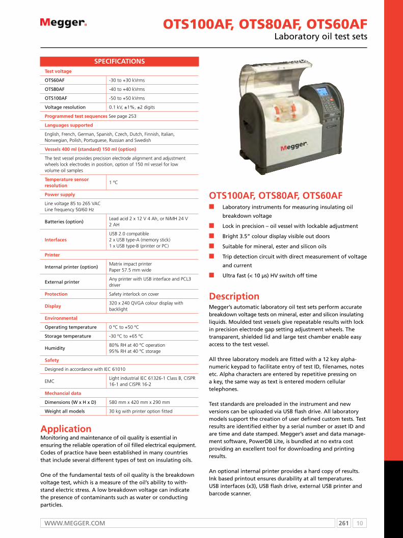
261 10WWW.mEggER.com
OTS100AF, OTS80AF, OTS60AFn Laboratory instruments for measuring insulating oil
breakdown voltage
n Lock in precision – oil vessel with lockable adjustment
n Bright 3.5” colour display visible out doors
n Suitable for mineral, ester and silicon oils
n Trip detection circuit with direct measurement of voltage
and current
n Ultra fast (< 10 µs) HV switch off time
Descriptionmegger’s automatic laboratory oil test sets perform accurate breakdown voltage tests on mineral, ester and silicon insulating liquids. moulded test vessels give repeatable results with lock in precision electrode gap setting adjustment wheels. The transparent, shielded lid and large test chamber enable easy access to the test vessel.
All three laboratory models are fitted with a 12 key alpha-numeric keypad to facilitate entry of test ID, filenames, notes etc. Alpha characters are entered by repetitive pressing ona key, the same way as text is entered modern cellulartelephones.
Test standards are preloaded in the instrument and new versions can be uploaded via USB flash drive. All laboratory models support the creation of user defined custom tests. Test results are identified either by a serial number or asset ID and are time and date stamped. megger’s asset and data manage-ment software, PowerDB Lite, is bundled at no extra cost providing an excellent tool for downloading and printing results.
An optional internal printer provides a hard copy of results. Ink based printout ensures durability at all temperatures. USB interfaces (x3), USB flash drive, external USB printer and barcode scanner.
SPECIFICATIONS
Test voltage
oTS60AF -30 to +30 kVrms
oTS80AF -40 to +40 kVrms
oTS100AF -50 to +50 kVrms
Voltage resolution 0.1 kV, ±1%, ±2 digits
Programmed test sequences See page 253
Languages supported
English, French, German, Spanish, Czech, Dutch, Finnish, Italian, Norwegian, Polish, Portuguese, Russian and Swedish
Vessels 400 ml (standard) 150 ml (option)
The test vessel provides precision electrode alignment and adjustment wheels lock electrodes in position, option of 150 ml vessel for low volume oil samples
Temperature sensor resolution
1 ºC
Power supply
Line voltage 85 to 265 VACLine frequency 50/60 Hz
Batteries (option)Lead acid 2 x 12 V 4 Ah, or NiMH 24 V 2 AH
InterfacesUSB 2.0 compatible2 x USB type-A (memory stick)1 x USB type-B (printer or PC)
Printer
Internal printer (option)Matrix impact printerPaper 57.5 mm wide
External printerAny printer with USB interface and PCL3 driver
Protection Safety interlock on cover
Display320 x 240 QVGA colour display with backlight
Environmental
operating temperature 0 ºC to +50 ºC
Storage temperature -30 ºC to +65 ºC
Humidity80% RH at 40 ºC operation95% RH at 40 ºC storage
Safety
Designed in accordance with IEC 61010
EMCLight industrial IEC 61326-1 Class B, CISPR 16-1 and CISPR 16-2
Mechancial data
Dimensions (W x H x D) 580 mm x 420 mm x 290 mm
Weight all models 30 kg with printer option fitted
SPECIFICATIONS
OTS100AF, OTS80AF, OTS60AFLaboratory oil test sets
Applicationmonitoring and maintenance of oil quality is essential in ensuring the reliable operation of oil filled electrical equipment. codes of practice have been established in many countries that include several different types of test on insulating oils.
one of the fundamental tests of oil quality is the breakdown voltage test, which is a measure of the oil’s ability to with-stand electric stress. A low breakdown voltage can indicate the presence of contaminants such as water or conducting particles.

10 262 T: + 44 (0) 1304 502100 E: [email protected]
OTS100AF, OTS80AF, OTS60AFLaboratory oil test sets
ORDERING CONFIGURATIONExample of an ordering configuration:-
OTS100AF-USA-P4 = This order is for an OTS100AF with US power lead, ASTM electrode set, internal printer and lid stirrer.
Model: OTS AF- -Weights
100 kV 100 29.5 kg
Select 80 kV 80 29.5 kgmodel
60 kV 60 29.5 kg
EU lead EU
UK lead UKSelect powercord
US lead US
Australian AUlead
No plug BLlead
ASTM Aset
Selectelectrode IEC set E
set
Full set U
Internal P 0.54 kgSelect printerprinteroption
No printer X 0.08 kg
Stirrer lid 4 0.3 kgSelect assemblystirrer fittedoption
Stirrer lid Xassemblynot fitted

263 10WWW.mEggER.com
ORDERING INFORMATION
Product Order Code
oTS60AF configured*
oTS80AF configured*
oTS100AF configured*
Included accessories (on all configurations)
Vessel 400 ml assembly
magnetic bead stirrers (2 off)
magnetic bead retriever
Feeler gauge set 1, 2, 2.5, 2.54 mm
User manual cD
PowerDB Lite software
configured accessories (to order additional or spares)
IEc60156 electrode Set - 12.7 mm spherical (2), 36 mm mushroom (2)
1001-477
ASTm D877/1816 electrode set - 25.4 mm cylindrical (2 std, and 2 none std), 36 mm mushroom (2)
1001-478
Full electrode set ASTm and IEc electrodes 1001-479
Vessel lid mounted impeller (ASTm D1816) for use with 400 ml vessel
1001-102
Product Order Code
optional accessories
Vessel 400 ml assembly (no electrodes supplied) 1001-473
Vessel 150 ml assembly (no electrodes supplied) 1001-474
Vcm100D digital voltage checker 1001-105
Vcm80D digital voltage checker 1001-801
Printer paper, 1 roll (moV applies) (4 rolls supplied if printer configured)
25995-001
Barcode reader, USB 1001-047
* See ordering configuration on previous page 670506
OTS100AF, OTS80AF, OTS60AFLaboratory oil test sets
country Standard
USASTM D1816-04ASTM D877A-02ASTM D877B-02
International IEC 60156-95
UK BS-EN-60156-95
Italy CEI EN-60156-95
Argentina IRAM 2341
Spain UNE EN 60156
France NF EN 60156
South Africa SABS EN 60156
germany VDE 0370 Part 5
Australia AS 1767.2.1
JapanJIS C2101-99 (M)JIS CS101-99 (S)
custom Configurable by user
India IS-6729
Programmed test sequences

10 264 T: + 44 (0) 1304 502100 E: [email protected]
VCM100D/VCM80Doil test set calibration meter
VCM100D/VCM80D
DescriptionThe Vcm100D/Vcm80D voltage check meters are used as a
high voltage meter for megger’s new oil Test Set (oTS) family.
This family includes the following models:
n Laboratory units: oTS100AF, oTS80AF and oTS60AF, the
oTS100AF requires a Vcm100D to check votages above
80 kV.
n Portable units: oTS80PB, oTS60PB.
The meters enable the high voltage output to be checked.
Operation
New oTS models are programmed with a test sequence
suitable for using the Vcm100D/Vcm80D. This sequence
causes the output of the oil test set to ramp up from 0 kV to
the maximum voltage value, pausing at each 10 kV point for
10 seconds to allow the voltage output to be checked.
Simply replace the oTS test vessel with the Vcm100D/
Vcm80D, close the lid and navigate to, the Vcm function on
the tools tab. Select using the oK button. After pressing the
TEST button, the test will proceed automatically. Read the
Vcm100D/Vcm80D meter when each steady voltage is
displayed up to the maximum instrument voltage.
Meter type
Proprietary 100 kV/80 kV Megger OTS voltmeter with 4 digit readout
Accuracy at 23 ºC
2.0% +2 digits to 50 kVrms2.5% +2 digits >50 kVrms to 75 kVrms3.0% +2 digits >75 kVrms to 100 kVrms
Environmental
operating temperature 0 ºC to 40 ºC
Storage temperature -30 ºC to +70 ºC
operational temperature 50% RH at 20 ºC
Storage temperature 93% RH at 40 ºC
Safety
The meter is only approved for use with Megger oil test sets
Mechanical data
Dimensions (W x H x D) 250 mm x 150 mm x 115 mm
Weight 1.8 kg
SPECIFICATIONS
ORDERING INFORMATIONProduct Order Code
Vcm100
Vcm80D
Included accessories
carrying case 6420-094
Instruction card 6172-044
certification of calibration

265 10WWW.mEggER.com
KF875 and KF-LAB MkIIKarl Fischer moisture in oil test sets
KF875 and KF-LABn coulometric Karl Fischer titrimetry
n KF875 optimized for insulating oil with an Sg of 0.875, completely portable
n KF-LAB mkII offers greater flexibility, versatility and sample data input than the KF875; also completely portable
n KF-LAB mkII analyzes materials with an Sg between 0.6 & 1.4, plus insulating oils with an Sg of 0.875
Descriptionover 20 years experience has led to the development of the
megger KF875 and KF-LAB mkII coulometric Karl Fischer Test
Sets designed to determine moisture in oil, to provide highly
accurate results on-site. The KF875 and KF-LAB mkII are highly
portable instruments, complete with integral printer and
carrying case, are easy to use and provide highly accurate
results.
Applicationoptimized for testing insulating oils with a specific gravity
of 0.875, the megger KF875 simply requires the operator to
press one button and inject a 1 ml sample into the test cell.
The simple ‘one touch’ operation makes the KF875 so easy to
use that it requires no specialist knowledge or training to use
it effectively. Results are presented on the instrument display
and on the integral printer in both micrograms of water and
in milligrams per kilogram (parts per million, ppm).
The KF-LAB mkII allows the titration of samples with a range
of specific gravities from 0.60 to 1.40 and also permits the use
of different sample sizes. The KF-LAB mkII also has a default
setting optimized for analyzing insulating oils with an Sg of
0.875. This means it can be used to measure water content in
a variety of different materials but is also easy to set up for
transformer insulating oils.
Reagents
Reagents and other consumable chemicals for coulometric
Karl Fischer Titration are available from many different
suppliers throughout the world.
megger recommends the use of:
Part numbers for “Hydranal coulomat” Reagents are: Part no. DescriptionRH-34807 Hydranal coulomat A anode reagent - 500 ml bottle RH-34840-25 Hydranal coulomat cg cathode reagent - 1 x 25 ml vial RH-34840-50 Hydranal coulomat cg cathode reagent - 1 x 10 pack of 50 ml ampoules
Part numbers for “Hydranal” water standards are: Part no. DescriptionRH-34828 Hydranal water standard 1.00 - 10 pack of 4 ml ampoules RH-34847 Hydranal water standard 0.10 - 10 pack of 4 ml ampoules Details of a local agent where these products can be obtained are available on the Sigma-Aldrich website www.sigmaaldrich.com

10 266 T: + 44 (0) 1304 502100 E: [email protected]
SPECIFICATIONSKF-LAB KF875
Titration method Coulometric Karl Fischer Titration
Electrolysis control Patented “ACE” control system
End point detection AC polarisation
End point indication Visual display / print out / acoustic beep
measuring range 1 µg - 10 mg water
moisture range 1 ppm - 100% 1 ppm - 100 ppm
max. sensitivity 0.1 µg
max. titration speed 2 mg per minute
max. current 400 ma
Drift compensation Automatically controlled
Precision 10-100 µg ± 3 µg, 100 µg - 1 mg ± 5 µg, above 1 mg ± 0.5%
method storage 10 programmable methods Preset method
Sample ID number User programmable Not available
Display format µf, mg/kg, ppm, % mg/kg, ppm
Print format µg + mg/kg, ppm % µg + mg/kg, ppm
calculation modes
Weight/weightWeight/dilution ratio
Volume/volumeVolume/density
User programmable
Volume/densityPreset values
StatisticsUp to 99 runs
User programmablePreset up to 99 runs
Start delay time 0-30 mins. selectable Preset
min. titration time 0-30 mins. selectable Not available
LanguageEnglish, Français, Español,
Portuguese, Deutsch, MagyarEnglish
Stirrer speed Microprocessor controlled
calendar/clock Anaylsis time and date print out
Keypad/user controls Non tactile membrane/display prompted menu
Display 40 character alphanumeric backlit display
Printer 42 character high speed thermal printer
carry case Standard
Power supply90 - 264 V ac, 47 - 63 Hz
12 V dc car adapter/ internal battery
Battery life 8 hours running time
Battery low Display and print out indication
Enviromental
operating temperature 0 ºC to 45 ºC
Storage temperature -10 ºC to +85 ºC
Humidity 5% to 95%
Output
Dimensions (W x H x D) 87 mm x 95 mm x 29 mm
Weight 0.16 kg
SPECIFICATIONS
ORDERING INFORMATIONProduct Order Code
KF-LAB mk II Laboratory coulometric Karl Fischer test set
6111-774
KF875 coulmetric Karl Fischer test set for insulating oils
6111-636
Supplied accessories (also available as spare items)
Titration vessel 6121-527
Detector electrode 6121-528
generator electrode 6121-529
Drying tube 6121-530
carrying case 6121-537
Power pack 6121-538
Product Order Code
car adapter 6121-539
Injection septa (10) 6121-531
glass syringe (1 ml) 6121-532
Luer needle 6121-533
Bottle of molecular sieve 6121-534
Stirrer bar 6121-535
Funnel 6121-536
KF875 and KF-LAB MkIIKarl Fischer moisture in oil test sets

267 10WWW.mEggER.com
MTO210Transformer ohmmeter
MTO210n Direct 2-channel digital reading (1 mW to 2000 W)
n Dc test current up to 10 A maximum
n Patented “Quick Test” measurement technique
n 0.25% measurement accuracy
n Integrated demagnetization feature
n Tests operation of on-load tap-changers
n Very fast auto safety discharge circuit
DescriptionThe mTo210 transformer ohmmeter is a line-operated,
field-portable instrument designed specifically to measure
the dc resistance of all types of magnetic windings safely
and accurately. It can test transformers and rotating machine
windings and perform low-current resistance measurements
on connections, contacts and control circuits.
The dual set of potential inputs measures the resistance of the
primary and secondary windings of a single- or three-phase
transformer simultaneously. This dual reading, dual injection
characteristic, also help to speed up the measurements
when used to test LV windings on large three-phase power
transformers.
The transformer ohmmeter is extremely useful when testing
the windings and contact resistance of tap-changers with
“make-before-break” contacts and voltage regulators. This
action will check for pitted or misaligned contacts as the
instrument will give an indication if either condition occurs.
Users are also protected by the auto-shutdown safety feature.
Any inadvertent disconnection of a test lead or loss of power
to the instrument will safely discharge the energy stored in
the test sample.
ApplicationThe mTo210 transformer ohmmeter is used:
n To verify factory test readings.
n As part of a regular maintenance program.
n To help locate the presence of defects in transformers, such
as loose connections.
n To check the “make-before-break” operation of on-load
tap-changers.
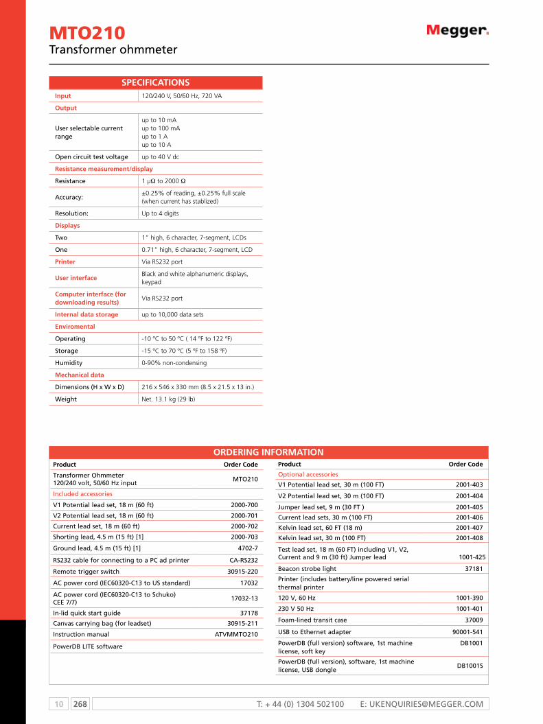
10 268 T: + 44 (0) 1304 502100 E: [email protected]
MTO210Transformer ohmmeter
ORDERING INFORMATIONProduct Order Code
Transformer ohmmeter 120/240 volt, 50/60 Hz input
mTo210
Included accessories
V1 Potential lead set, 18 m (60 ft) 2000-700
V2 Potential lead set, 18 m (60 ft) 2000-701
current lead set, 18 m (60 ft) 2000-702
Shorting lead, 4.5 m (15 ft) [1] 2000-703
ground lead, 4.5 m (15 ft) [1] 4702-7
RS232 cable for connecting to a Pc ad printer cA-RS232
Remote trigger switch 30915-220
Ac power cord (IEc60320-c13 to US standard) 17032
Ac power cord (IEc60320-c13 to Schuko)cEE 7/7)
17032-13
In-lid quick start guide 37178
canvas carrying bag (for leadset) 30915-211
Instruction manual ATVmmTo210
PowerDB LITE software
Product Order Code
optional accessories
V1 Potential lead set, 30 m (100 FT) 2001-403
V2 Potential lead set, 30 m (100 FT) 2001-404
Jumper lead set, 9 m (30 FT ) 2001-405
current lead sets, 30 m (100 FT) 2001-406
Kelvin lead set, 60 FT (18 m) 2001-407
Kelvin lead set, 30 m (100 FT) 2001-408
Test lead set, 18 m (60 FT) including V1, V2, current and 9 m (30 ft) Jumper lead 1001-425
Beacon strobe light 37181
Printer (includes battery/line powered serial thermal printer
120 V, 60 Hz 1001-390
230 V 50 Hz 1001-401
Foam-lined transit case 37009
USB to Ethernet adapter 90001-541
PowerDB (full version) software, 1st machine license, soft key
DB1001
PowerDB (full version), software, 1st machine license, USB dongle
DB1001S
Input 120/240 V, 50/60 Hz, 720 VA
Output
User selectable current range
up to 10 mA up to 100 mA up to 1 A up to 10 A
open circuit test voltage up to 40 V dc
Resistance measurement/display
Resistance 1 µW to 2000 W
Accuracy:±0.25% of reading, ±0.25% full scale (when current has stablized)
Resolution: Up to 4 digits
Displays
Two 1” high, 6 character, 7-segment, LCDs
one 0.71” high, 6 character, 7-segment, LCD
Printer Via RS232 port
User interfaceBlack and white alphanumeric displays, keypad
Computer interface (for downloading results)
Via RS232 port
Internal data storage up to 10,000 data sets
Enviromental
operating -10 ºC to 50 ºC ( 14 ºF to 122 ºF)
Storage -15 ºC to 70 ºC (5 ºF to 158 ºF)
Humidity 0-90% non-condensing
Mechanical data
Dimensions (H x W x D) 216 x 546 x 330 mm (8.5 x 21.5 x 13 in.)
Weight Net. 13.1 kg (29 lb)
SPECIFICATIONS
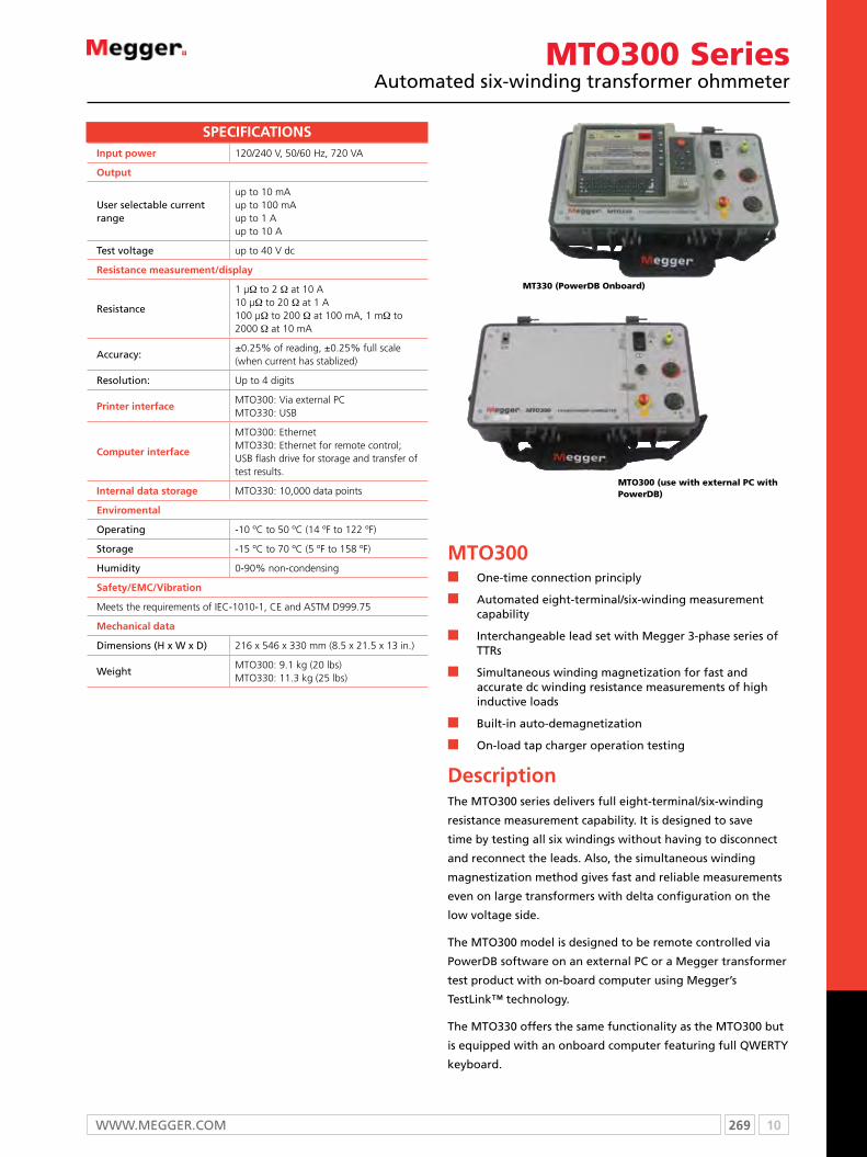
269 10WWW.mEggER.com
MTO300 SeriesAutomated six-winding transformer ohmmeter
MT330 (PowerDB Onboard)
MTO300 (use with external PC with PowerDB)
MTO300n one-time connection principly
n Automated eight-terminal/six-winding measurement capability
n Interchangeable lead set with megger 3-phase series of TTRs
n Simultaneous winding magnetization for fast and accurate dc winding resistance measurements of high inductive loads
n Built-in auto-demagnetization
n on-load tap charger operation testing
DescriptionThe mTo300 series delivers full eight-terminal/six-winding
resistance measurement capability. It is designed to save
time by testing all six windings without having to disconnect
and reconnect the leads. Also, the simultaneous winding
magnestization method gives fast and reliable measurements
even on large transformers with delta configuration on the
low voltage side.
The mTo300 model is designed to be remote controlled via
PowerDB software on an external Pc or a megger transformer
test product with on-board computer using megger’s
TestLink™ technology.
The mTo330 offers the same functionality as the mTo300 but
is equipped with an onboard computer featuring full QWERTY
keyboard.
Input power 120/240 V, 50/60 Hz, 720 VA
Output
User selectable current range
up to 10 mA up to 100 mA up to 1 A up to 10 A
Test voltage up to 40 V dc
Resistance measurement/display
Resistance
1 µW to 2 W at 10 A10 µW to 20 W at 1 A100 µW to 200 W at 100 mA, 1 mW to 2000 W at 10 mA
Accuracy:±0.25% of reading, ±0.25% full scale (when current has stablized)
Resolution: Up to 4 digits
Printer interfaceMTO300: Via external PCMTO330: USB
Computer interface
MTO300: EthernetMTO330: Ethernet for remote control; USB flash drive for storage and transfer of test results.
Internal data storage MTO330: 10,000 data points
Enviromental
operating -10 ºC to 50 ºC (14 ºF to 122 ºF)
Storage -15 ºC to 70 ºC (5 ºF to 158 ºF)
Humidity 0-90% non-condensing
Safety/EMC/Vibration
Meets the requirements of IEC-1010-1, CE and ASTM D999.75
Mechanical data
Dimensions (H x W x D) 216 x 546 x 330 mm (8.5 x 21.5 x 13 in.)
WeightMTO300: 9.1 kg (20 lbs)MTO330: 11.3 kg (25 lbs)
SPECIFICATIONS

10 270 T: + 44 (0) 1304 502100 E: [email protected]
MTO300 SeriesAutomated six-winding transformer ohmmeter
ORDERING INFORMATIONProduct Order Code
Transformer ohmmeter 120/240 volt, 50/60 Hz input
mTo300
Transformer ohmmeter, with on-board computer, 120/240 V, 50/60 Hz input
mTo330
Included accessories
Ac power cord (IEc60320-c13 to US Standard) 17032
Ac power cord (IEc60320-c13 to Schuko cEE 7/7)
17032-13
cAT5e patch cable 36798
Instruction manual ATVmmTo300
PowerDB Basic
USB to ethernet adapter (to connect Pc to mTo300)
90001-541
Product Order Code
optional accessories
USB portable thermal printer (120 V) 36493-1
USB portable thermal printer (230 V) 36494-1-kit
Foam lined transit case 37009
PowerDB Pro software 1st machine license, softkey
DB1001
PowerDB Pro software 1st machine license, USB dongle
DB1001S
Remote hand switch 309150-220
Universal leads sets, compatible with megger TTR300 Series products (up to 10 A Dc max)
3-phase shielded test lead set, X and H windings
18 m (60 ft) 36486-5
9 m (30 ft) 36486-6
10 m (33 ft) extension 36486-9
ground lead, 4.5 m (15 ft) 4702-7
canvas carry bag 30915-211
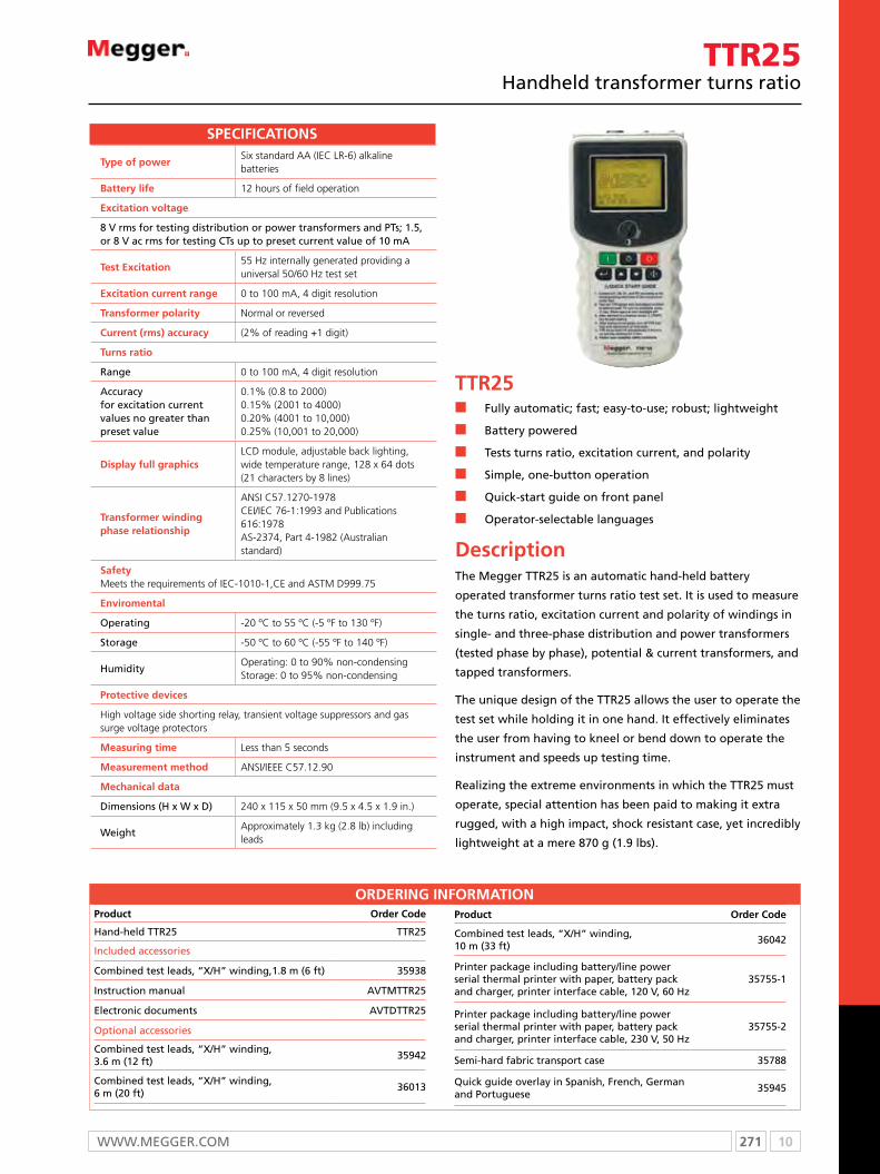
271 10WWW.mEggER.com
TTR25Handheld transformer turns ratio
TTR25n Fully automatic; fast; easy-to-use; robust; lightweight
n Battery powered
n Tests turns ratio, excitation current, and polarity
n Simple, one-button operation
n Quick-start guide on front panel
n operator-selectable languages
DescriptionThe megger TTR25 is an automatic hand-held battery
operated transformer turns ratio test set. It is used to measure
the turns ratio, excitation current and polarity of windings in
single- and three-phase distribution and power transformers
(tested phase by phase), potential & current transformers, and
tapped transformers.
The unique design of the TTR25 allows the user to operate the
test set while holding it in one hand. It effectively eliminates
the user from having to kneel or bend down to operate the
instrument and speeds up testing time.
Realizing the extreme environments in which the TTR25 must
operate, special attention has been paid to making it extra
rugged, with a high impact, shock resistant case, yet incredibly
lightweight at a mere 870 g (1.9 lbs).
Type of powerSix standard AA (IEC LR-6) alkaline batteries
Battery life 12 hours of field operation
Excitation voltage
8 V rms for testing distribution or power transformers and PTs; 1.5, or 8 V ac rms for testing cTs up to preset current value of 10 mA
Test Excitation55 Hz internally generated providing a universal 50/60 Hz test set
Excitation current range 0 to 100 mA, 4 digit resolution
Transformer polarity Normal or reversed
Current (rms) accuracy (2% of reading +1 digit)
Turns ratio
Range 0 to 100 mA, 4 digit resolution
Accuracyfor excitation current values no greater than preset value
0.1% (0.8 to 2000)0.15% (2001 to 4000)0.20% (4001 to 10,000)0.25% (10,001 to 20,000)
Display full graphicsLCD module, adjustable back lighting, wide temperature range, 128 x 64 dots (21 characters by 8 lines)
Transformer winding phase relationship
ANSI C57.1270-1978CEI/IEC 76-1:1993 and Publications 616:1978AS-2374, Part 4-1982 (Australian standard)
SafetyMeets the requirements of IEC-1010-1,CE and ASTM D999.75
Enviromental
operating -20 ºC to 55 ºC (-5 ºF to 130 ºF)
Storage -50 ºC to 60 ºC (-55 ºF to 140 ºF)
HumidityOperating: 0 to 90% non-condensingStorage: 0 to 95% non-condensing
Protective devices
High voltage side shorting relay, transient voltage suppressors and gas surge voltage protectors
Measuring time Less than 5 seconds
Measurement method ANSI/IEEE C57.12.90
Mechanical data
Dimensions (H x W x D) 240 x 115 x 50 mm (9.5 x 4.5 x 1.9 in.)
WeightApproximately 1.3 kg (2.8 lb) including leads
SPECIFICATIONS
ORDERING INFORMATIONProduct Order Code
Hand-held TTR25 TTR25
Included accessories
combined test leads, “X/H” winding,1.8 m (6 ft) 35938
Instruction manual AVTmTTR25
Electronic documents AVTDTTR25
optional accessories
combined test leads, “X/H” winding, 3.6 m (12 ft)
35942
combined test leads, “X/H” winding, 6 m (20 ft)
36013
Product Order Code
combined test leads, “X/H” winding, 10 m (33 ft)
36042
Printer package including battery/line power serial thermal printer with paper, battery pack and charger, printer interface cable, 120 V, 60 Hz
35755-1
Printer package including battery/line power serial thermal printer with paper, battery pack and charger, printer interface cable, 230 V, 50 Hz
35755-2
Semi-hard fabric transport case 35788
Quick guide overlay in Spanish, French, german and Portuguese
35945

10 272 T: + 44 (0) 1304 502100 E: [email protected]
TTR100Handheld transformer turns ratio
TTR100n Single- and three-phase transformer testing
n Fully automatic; fast; easy-to-use; handheld; robust; lightweight
n Battery powered with power-saving and shutdown function
n Tests turns ratio, phase displacement, excitation current, winding resistance and polarity
n RS232 for data transfer and printing
n Stores 200 test results and 100 user-defined transformer test settings
DescriptionThe megger TTR100 is an automatic handheld, battery
operated transformer turns ratio test set used to measure
the turns ratio, excitation current, phase displacement, dc
resistance and polarity of windings in single- and three-phase
distribution transformers (tested phase by phase), potential &
current transformers, and tapped transformers. Deviations in
the mentioned measurements will quickly indicate problems
in transformer windings or in the magnetic core circuits.
The unique design of the TTR100 allows the user to
operate the test set while holding it in one hand. No other
transformer test set offers this capability. It effectively relieves
the user from having to kneel or bend down to operate the
instrument and speeds up testing time.
TTR100 often has to operate in extreme environments and
special attention has been paid to making it extra rugged,
with a high impact, shock resistant case, yet very lightweight
at 1.5 kg (3.3 lb.).
Type of powerRechargeable NiMH battery pack, 3.6 V dc, 3800 mAh
Battery life 15 hours of field operation
Optional charger source
Optional inverter 12 V dc to 115 V ac for powering a charger from vehicle battery (non CE marked)
Excitation voltage
8 V rms for testing distribution or power transformers and PTs; 1.5, or 8 V ac rms for testing CTs up to preset current value of 10 mAThe excitation voltage is switched automatically if excitation current exceeds a preset value
Test frequency55 Hz internally generated providing a universal 50/60 Hz test set
Excitation current range 0 to 100 mA, 4 digit resolution
Phase deviation
Range±90º, 1 decimal point for the minutes displayed, 2 decimal points for the degree display, or for the centiradian display
Accuracy ±3 minutes
Winding resistance
Range 0 to 2000 W, 4 digit resolution
Accuracyfor excitation current values no greater than preset value
±10% (0.8 to 2000)±0.15% (2001 to 4000)±0.20% (4001 to 10,000)±0.25% (10,001 to 20,000)
Turns ratio
Range
8 V ac: 0.8 to 20,000, 5 digit resolution (for transfomers and PT testing)1.5 V ac: 5.0 to 2200, 5 digit resolution (for CT testing)
Accuracy
0.1% (0.8 to 2000)±0.20% (2001 to 4000)0.25% (4001 to 10,000)±0.30% (10,001 to 20,000)
Transformer
Vector group 1PH0 or 1PH6
Polarity Additive and subtractive
PC/Printer interfaceRS232C port, 9 pin, 57.6 Kbaud (19.2 Kbaud for the printer)
Display full graphicsLCD module, wide temperature range, 128 x 64 dots (21 characters by 8 lines)
Test result storage
Internal, nonvolatile memory for storing up to 200 sets of single-phase measured and calculated ratio, exciting current, phase, ratio error, winding resistance, polarity, vector group, plus header information (company, substation,transformer manufacturer, transformer rating, instrument serial number, temperature, relative humidity and operator name). In additon, up to 100 user-defined transformer settings can be stored.
Computer software
Included software for downloading of data to a PC, data storage to database and report printout.
Safety/EMC/VibrationMeets the requirements of IEC-1010-1,CE and ASTM D999.75
Specifications continued
SPECIFICATIONS
273 10WWW.mEggER.com
Enviromental
operating -20 ºC to 55 ºC (-5 ºF to 130 ºF)
Storage -50 ºC to 60 ºC (-55 ºF to 140 ºF)
HumidityOperating: 0 to 90% non-condensingStorage: 0 to 95% non-condensing
Transformer winding phase relationship
ANSI C57.12.70-1978CEI/IEC 76-1:1993 and Publication 616:1978AS-2374, Part 4-1982 (Australian Standard)
Mechanical data
Dimensions (H x W x D) 240 x 115 x 48 mm (9.5 x 4.5 x 1.875 in.)
WeightApproximately 1.5 kg (3.3 lb) including leads
order a TTR100 configured to your specific application. To determine the catalog number, fill in the blanks below with the corresponding number from the detailed information boxes.
ordering Example:
To order a TTR100 for North American application, without a deluxe kit, and instruction manual in the English language, request catalog number TTR100-NA0-ENg TTR100 — N A 0 — E N G
To order a TTR100 for North American application, with a deluxe kit, and instruction manual in the English language, request catalog number TTR100-NA1-ENg TTR100 — N A 1 — E N G
Fill in these blanks with the corresponding letter or number.
TTR100 — X X X — X X X
ORDeRIng InFORMATIOn
Country
NA = North America
UK = United Kingdom
EU = European Union
(Determines power cord requirement)
Deluxe Kit Option
0 = No Kit
1 = Deluxe Kit, 120 V, 60 Hz printer package
2 = Deluxe Kit, 230 V, 50 Hz printer package
(Kit consists of TTR100, included
accessories as well as all optional accessories, excluding Inverter P/N 35973)
Instruction Manual
ENG = English
FRN = French
SPN = Spanish
Product Order code
Included accessories
Test Leads
“X” winding, 1.8 m (6 ft) 35502-511
“H” winding, 1.8 m (6 ft) 35502-521
Pc interface cable 33147-18
Battery pack 35753
Universal battery charger 35757
Power cable for battery charger Determined by country
Protective neoprene carrying case and accessory pouch 55-20008
Software for uploading test results to a Pc 35794-2
Quickstart guide 55-20013
Instruction manual AVTmTTR100-XXX (XXX = language code)
optional accessories
Test Leads
“X” winding, 3.6 m (12 ft) 35502-510
“H” winding, 3.6 m (12 ft) 35502-520
“X” winding, 6 m (20 ft) 35502-512
Product Order code
“H” winding, 6 m (20 ft) 35502-519
Semi-hard fabric transport case 35788
Additional battery pack 35753
Inverter cigarette adapter with power cable, 12 V dc to 115 V ac, 60 Hz, non cE marked 35973
Printer package, including battery/line power serial thermal printer with paper, battery pack, battery charger, printer interface cable, 120 V, 60 Hz 35755-1
Printer package, including battery/line power serial thermal printer with paper, battery pack, battery charger, printer interface cable, 230 V, 50 Hz 35755-2
Additional printer paper (1 roll) 27705-1
Optional accessories are ordered separately or with Deluxe Kit
TTR100Handheld transformer turns ratio
10 274 T: + 44 (0) 1304 502100 E: [email protected]
TTR300Three-phase transformer turns ratio test sets
TTR300n Stand-alone or remote-control operation
n Accurately measures ratio, phase deviation and exciting current
n Field upgradeable without compromise to calibration
n Built-in capability for storing and downloading test results in an XmL format, via RS-232, Ethernet or USB ports (depending on model)
n Works in the presence of high interference/high voltage
n Highest ratio measurement (45,000:1); highest accuracy (0.1%)
n Displays % error vs. name plate with pass/fail limits
DescriptionThe TTR300 series of three-phase transformer turns ratio
test sets are designed to measure the turns ratio of power,
instrument, and distribution transformers in a substation or
manufacturing environment. A rugged and robust design
makes these instruments well suited for use in a variety of
harsh environments. our leads are specially designed to
provide the necessary flexibility needed in cold weather.
The TTR300 series are ideal for use by power transformer
manufacturers. Their unique testing procedures and storage
capability allows an operator to set up and test difficult three-
phase transformers (with multiple tap changers and bushing
cTs) in a fraction of the time than it used to take with other
TTRs. This test also includes a pass/fail limit of individual ratios.
The TTR300 Series also measure the phase deviation of the
transformer primary versus secondary. This quickly indicates
problems in the transformer such as partial shorted turns and
core faults. This measurement is also useful in verifying phase
errors in all types of PTs and cTs.
TTR330 shown
Input power120/230 V ac ±10%, single phase, 50/60 ±2 Hz 100 VA
Battery operation (optional)
Inverter 12 V dc to120 V/230 V ac for operation from vechicle battery
Excitation voltage8, 40 or 80 V rms, automatically or manually selected
Excitation current range and accuracy
0 to 500 mA, 3 digit resolution, ±(2% of reading +1 digit)
Phase deviation
Range±90º, 1 decimal point for the minutes displayed, 2 decimal points for the degree display, or for the centiradian display
Accuracy ±3 minutes
Turns ratio
Range
8 V ac: ±0.1% (0.8 to 2000)±0.25% (2001 to 4000) ±0.35% (4001 to 8000)40 V ac: ±0.1% (0.8 to 2000) ±0.15% (2001 to 4000)±0.3% (4001 to 10,000)±0.35% (10,001 to 25,000)80 V ac: ±0.1% (0.8 to 2000)±0.15% (2001 to 4000)±0.25% (4001 to 10,000)±0.30% (10,001 to 45,000)
Resolution 5 digit for all ratios
PC/Printer interface
TTR300 Not applicable
TTR310 RS232 port
TTR330 USB
interface
TTR300 and TTR310 RS232 port
TTR330 Ethernet
Safety/EMC/Vibration
Meets the requirements of IEC1010-1, CE and ASTM D999.75
Enviromental
operating temperature -5 ºC to 50 ºC (23 ºF to 122 ºF)
Storage temperature -50 ºC to 60 ºC (-58 ºF to 140 ºF)
Humidity 0 to 90% non-condensing
Measuring time8 to 20 seconds depending on mode of operation and type of transformer
Measuring method ANSI/IEEE C57.12.90
Mechanical data
Dimensions (H x W x D)216 x 546.1 x 330.2 mm. (8.5 x 21.5 x 13 in)
Weight (instrument only)TTR300: 9.1 kg (20 lbs)TTR310: 10.4 kg (23 lbs)TTR330: 11.3 kg (25 lbs)
SPECIFICATIONS

275 10WWW.mEggER.com
Field upgradeable/interchangeable to any other TTR in the series without
compromising calibration (patent pending) n n n
Remote controllable n n n
Works in the presence of high interference/high voltage n n n
Displays % error vs. name plate with pass/fail limits n n n
Measures the widest turns ratio range in the industry
(45,000:1) and provides the highest accuracy (0.1%) n n n
Enables operator to enter the ratio of transformer and all
of its taps letting operator know immediately when a tap n n n
is outside acceptable limits so problem can be flagged
Equipped with “Remote TEST” switch for single person
testing, allowing the operator to test transformers with n n n
“LTCs” very quickly
Measures phase deviation of the transformer primary
versus secondary; quickly indicates problems in the n n n
transformer such as partial shorted turns and core faults.
Useful in verifying phase errors in PTs and CTs
Rugged, lightweight design ideal for a harsh field and
substation environment n n n
User selectable standards: ANSI, IEC, and Australian.
Meets IEC 1010 and other standards such as CSA and UL n n n
“Quick Test” mode provides a fast determination of
turns ratio for single- and three-phase transformers n n n
Units can be operated while in transit case n n n
Leads can stay connected while in transit case n n n
Printing of test results without the use of a computer 4” thermal 8.5” x 11”
spool paper thermal paper
Software
PowerDB LITE n n
“PowerDB ONBOARD” allows for operation of
the unit through on-screen customizable test n
forms (patent pending)
Full version PowerDB £ £ £
Communications port
Printer interface RS-232 USB
Internal data storage (data sets) 200 100,000
External storage device USB
Computer interface RS-232 RS-232 Ethernet
User interface
Display type 5.7” B&W 8.4” color VGA
On-screen view Text Test forms
Keypad Numeric QWERTY
TTR300 TTR310 TTR330
FeATUReS AnD BeneFITS gUIDe
n feature £ option
TTR300Three-phase transformer turns ratio test sets

10 276 T: + 44 (0) 1304 502100 E: [email protected]
TTR300Three-Phase transformer turns ratio test sets
ORDeRIng InFORMATIOnProduct Order Code
Three-Phase TTR, remote controlled TTR300
Three-Phase TTR, stand alone or remote controlled TTR310
Three-Phase TTR with PowerDB oNBoARD TTR330
Note: 120 V 50/60-Hz operation standard. For 230 V, 50/60-Hz operation Add -47 to Cat. No.
Included accessories
canvas carrying bag for test leads 30915-211
Power supply cord, 2.5 m (8 ft), 120 V 17032-4
Power supply cord, 2.5 m (8 ft), 230 V 17032-13
ground lead, 4.6 m (15 ft) 4702-7
Hand-held TEST switch assy for remote operation 30915-220
PowerDB LITE software
RS232 cable for connecting to a Pc for use with TTR300 and TTR310 cA-RS232
Ethernet cable for connecting to a Pc for use with TTR330 36798
Transformer Vector Voltage Diagram Set (for ANSI, IEc, and AS Standards) for TTR310 35314
Spare fuse kits:
for TTR300 and TTR310 35026-3
for TTR300-47 and TTR310-47 35026-4
for TTR330 35026-5
for TTR330-47 35026-2
Instruction manuals:
for TTR300 AVTmTTR300
for TTR310 AVTmTTR310
for TTR330 AVTmTTR330
Product Order Code
optional accessories
PowerDB software, 1st machine license, soft key DB1001
PowerDB, 1st machine license, USB dongle DB1001S
TTR check box 550555
3-ø lead set adapter to allow use of megger TTR c/N 550503 lead set (30915-xxx) 37087
3-ø TTR calibration standard 550055
3-ø shielded test lead set, X and H winding, 9.1 m (30 ft) 37093
3-ø shielded test lead set, X and H winding, 15 m (50 ft) 37094
1-ø shielded test lead set, X and H winding, 9.1 m (30 ft) 37095
Inverter with 0.91 m (3 ft) cigarette adapter cord
12 V dc to 120 V ac, 60 Hz 35271-1
12 V dc to 120 V ac, 50 Hz 35271-3
12 V dc to 230 V ac, 60 Hz 35271-2
12 V dc to 230 V ac, 50 Hz 35271-4
TTR printer package for TTR310 120 V, 60 Hz 1001-390
230 V, 50 Hz 1001-401
USB portable thermal printer (120 V) for TTR330 36493-1
USB portable thermal printer (230 V) for TTR330 36494-1
Thermal paper (8.5” x 11”) for printer 36809-1
Thermal paper (A4) for printer 36809-2
Replacement/spare battery pack for printer 37077
Transit case (for instrument, leads and accessories) 37009
Field upgrade kits
TTR330 interface panel 37089-1
TTR310 interface panel 37089-3
TTR300 interface panel 37089-4
Bushing clips (6) mc7144

277 10WWW.mEggER.com
FRAX SeriesSweep frequency response analyzers
Collecting fingerprint data using Frequency Response Analysis (FRA) is an easy way to detect electro-mechanical problems in power transformers and an investment that will save time and money.
FRAX seriesn Highest dynamic range and accuracy in the industry
n Smallest and most rugged FRA instrument in the industry
n Fulfills all international standards for SFRA
measurements
n Advanced analysis and decision support built into the
software
n Imports data from other FRA test sets
DescriptionPower transformers are some of the most vital components
in today’s transmission and distribution infrastructure.
Transformer failures cost enormous amounts of money in
unexpected outages and unscheduled maintenance. It is
important to avoid these failures and make testing and
diagnostics reliable and efficient.
The FRAX series of sweep frequency response analyzers
(SFRA) detects potential mechanical and electrical problems
that other methods are unable to detect. major utilities and
service companies have used the FRA method for more than a
decade. The measurement is easy to perform and will capture
a unique “fingerprint” of the transformer. The measurement
is compared to a reference “fingerprint” and gives a direct
answer if the mechanical parts of the transformer are
unchanged or not. Deviations indicate geometrical and/or
electrical changes within the transformer.
ApplicationPower transformers are specified to withstand mechanical
forces from both transportation and in-service events, such
as faults and lightning. However, mechanical forces may
exceed specified limits during severe incidents or when
the insulation’s mechanical strength has weakened due to
aging. A relatively quick test where the fingerprint response
is compared to a post event response allows for a reliable
decision on whether the transformer safely can be put back
into service or if further diagnostics is required.
FRAX detects problems such as:
n Winding deformations and displacements
n Shorted turns and open windings
n Loosened clamping structures
n Broken clamping structures
n core connection problems
n Partial winding collapse
n Faulty core grounds
n core movements

10 278 T: + 44 (0) 1304 502100 E: [email protected]
An example of low, medium and high frequencies
The figure above shows a single phase transformer after a service overhaul where, by mistake, the core ground never got connected (red), and after the core ground was properly connected (green). This potential problem clearly showed up at frequencies between 1 kHz and 10 kHz and a noticeable change is also visible in the 10 kHz - 200 kHz range.
FRAXSweep frequency response analyzer
Method basics
A transformer consists of multiple
capacitances, inductances and
resistors, a very complex circuit
that generates a unique finger-
print or signature when test
signals are injected at discrete
frequencies and responses are
plotted as a curve.
Capacitance is affected by the
distance between conductors.
Movements in the winding will
consequently affect capacitances
and change the shape of the
curve.
The SFRA method is based on comparisons between measured
curves where variations are detected. One SFRA test consists of
multiple sweeps and reveals if the transformer’s mechanical or
electrical integrity has been jeopardized.
Practical application
In its standard application, a “finger print” reference curve for
each winding is captured when the transformer is new or when
it is in a known good condition. These curves can later be used
as reference during maintenance tests or when there is reason to
suspect a problem.
The most reliable method is the time based comparison where
curves are compared over time on measurements from the same
transformer. Another method utilizes type based comparisons
between “sister transformers” with the same design. Lastly, a
construction based comparison can, under certain conditions, be
used when comparing measurements between windings in the
same transformer.
These comparative tests can be performed 1) before and after
transportation, 2) after severe through faults 3) before and
after overhaul and 4) as diagnostic test if you suspect potential
problems. One SFRA test can detect winding problems that
requires multiple tests with different kinds of test equipment or
problems that cannot be detected with other techniques at all.
The SFRA test presents a quick and cost effective way to assess
if damages have occurred or if the transformer can safely be
energized again. If there is a problem, the test result provides
valuable information that can be used as decision support when
determining further action.
Having a reference measurement on a mission critical transformer
when an incident has occurred is, therefore, a valuable investment
as it will allow for an easier and more reliable analysis.
Analysis and software
As a general guideline, shorted turns, magnetization and other
problems related to the core alter the shape of the curve in the
lowest frequencies. Medium frequencies represent axial or radial
movements in the windings and high frequencies indicate
problems involving the cables from the windings, to bushings
and tap changers.
The FRAX software provides numerous features to allow for
efficient data analysis. Unlimited tests can be open at the same
time and the user has full control on which sweeps to compare.
The response can be viewed in traditional Magnitude vs. Frequency
and/or Phase vs. Frequency view. The user can also choose to
present the data in an Impedance or Admittance vs. Frequency
view for powerful analysis on certain transformer types.
Features and benefitsn Smallest and most rugged FRA instrument in the industry).
n Guaranteed repeatability by using superior cabling technology, thus avoiding the introduction of error due to cable connection and positioning (which is common in other FRA manufacturers’ equipment).
n Fulfills all international standards for Sweep Frequency Response Analysis (SFRA) measurements (IEC 60076-18, Method 1).
279 10WWW.mEggER.com
FRAXSweep frequency response analyzer
n Highest dynamic range and accuracy in the industry allowing even the most subtle electro-mechanical changes within the transformer to be detected.
n Advanced analysis and support software tools allows for sound decision making with regard to further diagnostics analysis and/or transformer disposition.
n Built-in PC with powerful backlit screen for use in direct sunlight (FRAX 150).
1. Test Object Browser – Unlimited number of tests and sweeps. Full user control
2. Quick Select Tabs – Quickly change presentation view for different perspectives and analysis tools.
3. Quick Graph Buttons – Programmable graph setting lets you change views quickly and easily.
4. Sweep/Curve Settings – Every sweep can be individuallyturned on or off, change color, thickness and position.
5. Dynamic Zoom – Zoom in and move your focus to any part of the curve.
6. Operation Buttons – All essential functions at your fingertips; select with mouse, function keys or touch screen.
7. Automated analysis compares two curves using an algorithm that compare amplitude as well as frequency shift and lets you know if the difference is severe, obvious, or light.
Built-in-decision support is provided by using a built-in analysis tool based on the international standard DL/T 911-2004.
4 5 6
1 2 3
7

10 280 T: + 44 (0) 1304 502100 E: [email protected]
FRAX SeriesSweep frequency response analyzers
Considerations when performing SFRA measurements
SFRA measurements are compared over time or between
different test objects. This accentuates the need to perform the
test with the highest repeatability and eliminates the influence
from external parameters such as cables, connections and
instrument performance.
FRAX offers all the necessary tools to ensure that the measured
curve represents the internal condition of the transformer.
good connections Bad connections can compromise the test results which is why
FRAX offers a rugged test clamp that ensures good connection
to the bushings and solid connections to the instrument.
Contacts made with the C-clamp guarantee good connections
Shortest braid concept
The connection from the cable shield to ground has to be the
same for every measurement on a given transformer. Traditional
ground connections techniques have issues when it comes to
providing repeatable conditions. This causes unwanted variations
in the measured response for the highest frequencies that makes
analysis difficult.
The FRAX braid drops down from the connection clamp next
to the insulating discs to the ground connection at the base of
the bushing. This creates near identical conditions every time
you connect to a bushing whether it is tall or short and is the
recommended way of connecting in CIGRE TB342 and IEC
60076-18.
Solid connections using the C-clamps and the shortest braid
method to connect the shield to ground makes it possible to
eliminate connection problems and cable loops that otherwise
affect the measurement.
FRAX 150 with built-in PC
FRAX 150 has a built-in PC with a high contrast, powerful
backlit screen suitable for work in direct sunlight. The cursor
is controlled via the built-in joystick or using an external USB
mouse and the built-in keyboard makes data entry easy.
All data is stored on the built-in hard drive. The data can be
moved to any other computer using a USB memory stick.
Import and export
The FRAX software can import data files from other FRA
instruments making it possible to compare data obtained using
another FRA unit. FRAX can import and export data according to
the international XFRA standard format as well as standard CSV
and TXT formats.
Optimized sweep setting
The software offers the user an unmatched feature that allows
for fast and efficient testing. Traditional SFRA systems use a
logarithmic spacing of measurement points. This results in as
many test points between 20 Hz and 200 Hz as between
200 kHz and 2 MHz and a relatively long measurement time.
The frequency response from the transformer contains a few
resonances in the low frequency range but a lot of resonances
at higher frequencies. FRAX allows the user to specify less
measurement points at lower frequencies and high measurement
point density at higher frequencies. The result is a much faster
sweep with greater detail where it is needed.
Variable voltage
The applied test voltage may affect the response at lower
frequencies.Some FRA instruments do not use the 10 V peak-
to-peak used by major manufacturers and this may complicate
comparisons between tests. FRAX standard voltage is 10 V
peak-to-peak but FRAX also allows the user to adjust the applied
voltage to match the voltage used in a different test.
Dynamic range
Making accurate measurements in a wide frequency range with
high dynamics puts great demands on test equipment, test
leads, and test set up. FRAX is designed with these requirements
in mind. It is rugged, able to filter induced interference and
has the highest dynamic range and accuracy in the industry.
FRAX dynamic range or noise floor is shown in red below with
a normal transformer measurement in black. A wide dynamic
range, low noise floor, allows for accurate measurements in every
transformer. A margin of about 20 dB from the lowest response
to the instruments noise floor must be maintained to obtain ±1
dB accuracy.

281 10WWW.mEggER.com
FRAX SeriesSweep frequency response analyzers
Specifications are valid at nominal input voltage and an ambienttemperature of +25 °C, (77 °F). Specifications are subject to changewithout notice.
Environmental
Application fieldThe instrument is intended for use in medium and high-voltage substations and industrial environments
Ambient temperature
operatingFRAX150FRAX99/101Storage
-5°C to +50°C (23°F to +122°F)-20°C to +55°C (-4°F to +131°F)-20°C to 70°C (-4°F to +158°F)
Humidity < 95%RH, non-condensing
CE-marking
Emc 2004/108/EC
LVD 2006/95/EC
General
mains voltage 90 - 264 V AC, 47 - 63 Hz
Dimensions of instrument
FRAX150 305 x 194 x 360 mm (12” x 7.6” x 14.2”)
FRAX99/101 250 x 169 x 52 mm (9.84” x 6.65” x 2.05”)
Dimensions of transport case
FRAX150 -
FRAX99/101 520 x 460 x 220 mm (20.5” x 18.1” x 8.7”)
Weight of instrument
FRAX150 6 kg (13 lbs)
FRAX99/1011.4 kg (3.1 lbs)1.8 kg (4 lbs) with battery
Weight of case and accessories
FRAX150 16 kg (35 lbs)
FRAX99 15 kg (33 lbs)
FRAX101 12 kg (26 lbs)
Measurement section
Test method Sweep frequency (SFRA)
Frequency range 0.1 Hz – 25 MHz, user selectable
Frequency resolution <0.01%
Frequency inaccuracy <0.01%
Level resolution <0.001 dB
Number of pointsDefault 1046, up to 32 000 points, user selectable
measurement timeDefault 64 s, fast setting, 37 s (20 Hz - 2 MHz)
Points spacing Log., linear or both
Sweep settingsIndividual settings for customer definedfrequency bands. Linear and logarithmicscale or combination of both.
Dynamic range (IEc)120 bB (FRAX99)135 dB (FRAX101 and 150)
Inaccuracy
± 0.3 dB from +10 dB down to -40 dB± 0.5 dB down to -100 dB (FRAX 101/150)± 1 dB down to -100 dB (FRAX 99)
IF bandwith User selectable, default <10%
SPECIFICATIONS FRAX99/101/150
An example of a transformer measurement in comparison
with the internal noise level in FRAX
Built-in mouse with Left and Right click buttons (sealed to protect from dust and other contaminants)
Test button
Navigation arrows
CLOSe-UP OF FRAX 150 COnTROL PAneL
Enter key
10 282 T: + 44 (0) 1304 502100 E: [email protected]
Included accessories shown above: Mains cable, ground cable, (2) ground braid sets, (2) earth/ground braid leads (insulated), (2) C-clamps, generator cable, measure cable, field test box, nylon accessory pouch, (2) earth/ground braids with clamp, and canvas carrying bag for test leads
InCLUDeD ACCeSSORIeS
Specifications continued
PC communication
FRAX150 Internal USB (galvanically isolated)
FRAX101 Bluetooth and USB (galvanically isolated)
FRAX99 USB (galvanically isolated)
Software FRAX for Windows 2000/ XP/Vista/7
Standards/guides
Fulfill requirements in Cigré Brochure 342,2008Mechanical condition assessment oftransformer windings using FRA DL/T911-2004, FRA on winding deformationof power transformers, IEC 60076-18 andIEEE PC57.149 as well as other standardsand recommendations.
Analog output
channels 1
compliance voltage0.20 – 24 V p-p (FRAX 101/150)20 V p-p (FRAX 99)
measurement voltage at 50 W
0.1 – 12 V p-p (FRAX 101/150)10 V p-p (FRAX 99)
output impedance 50 W
Protection Short-circuit protected
Frequency range 0.1 Hz - 25 MHz
Sweep direction Low to high or high to low
Analog input
channels 2
Sampling Simultaneously
Frequency range 0.1 Hz - 25 MHz
Imput impedance 50 W
FRAX SeriesSweep frequency response analyzers
Sampling rate 100 MS/s
Pc (FRAX150)
operating system Windows® XP (embedded)
memory1000 records in internal memory External storage on USB stick
PC Requirements (FRAX 99/101) NOTE: PC not included
operating system Windows XP/Vista/7
Processor Pentium 500 MHz or higher
memory 256 Mb RAM or more
Hard drive Minimum 30 Mb free
InterfaceWireless/USB (FRAX99/101)USB and Ethernet (FRAX99)
FTB 101 Field test boxServal international FRA guides recommends to verify the integrity of cables and instrument before and after a test using a test crcuit with a known FRA response supplied by the equipment manufacturer. FRAX comes with a field test box FTB101 as a standard accessory and allows the user to perform this important validation in the field at any time and secure measurement quality.

283 10WWW.mEggER.com
FRAX SeriesSweep frequency response analyzers
ORDERING INFORMATION
Product Order Code
FRAX101 with accessories, 18 m (60 ft) cable set Ac-19091
with accessories incl. battery, 18 m cable set Ac-19091
with accessories, 9 m (30 ft) cable set Ac-19092
With accessories, incl. battery, 9 m (30 ft) cable set Ac-19093
FRAX99with accessories, 9 m (30 ft) cable set
Ac-29090
with accessories, 18 m (60 ft) cable set Ac-29092
with accessories, incl. battery, 9 m (30 ft) cable set Ac-29095
with accessories, incl. battery, 18 m (60 ft) cable set Ac-29096
FRAX150with accessories, 18 m (60 ft) cable set Ac-39090
with accessories, 9 m (30 ft) cable set Ac-39092
Included accessories for all models
generator cable
measuring cable
4 x 3 m (10 ft) ground braid set
2 x 0.3 m (1 ft) braid with clamp
2 x c-clamp (bushing connector clamp)
2 x g-clamp (ground clamp)
Field test box FTB101
mains cable
FRAX software for Windows
User manual
Product Order Code
Additional included accessories for FRAX99
Ac/Dc adapter
Light transport case
canvas carrying bag (for accessories)
USB cable
Additional included accessories for FRAX101
Ac/Dc adaptor
Transport case
Bluetooth adapter
USB cable
Additional included accessories for FRAX150
canvas carrying bag (for accessories)
optional accessories
calibration set Ac-90020
FRAX demo box FDB101 Ac-90050
FRAX generator and ref cable, 9 m (30 ft) gc-30040
FRAX generator anc ref cable, 18 m (60 ft) gc-30042
FRAX measure cable, 9 m (30 ft) gc-30050
FRAX measure cable, 18 m (60 ft) gc-30052
c-clamps gc-80010
E-clamp (single hand grip clamp) gc-80030
OPTIOnAL ACCeSSORIeS
FDB101The FRAX demo box FDB101 is a transformer kit that can b used for in-house training and deomstrations. The small transformer is a single-phase unit with capability to simulate normal as well as fault conditions. Open as well as shorted measurements can be performed. The unit also contains two test impedances, one of them the same as used in the FTB101 field test box.

10 284 T: + 44 (0) 1304 502100 E: [email protected]
MCT1605n one button automated test: Demagnetization, on
multi-ratio cTs test all Knee Point, Saturation, Polarity and Deviation, Winding Resistance, Insulation Resistance, and Burden
n Displays multiple instantaneous Saturation curves with Knee Point
n Integrated 1 kV Dc insulation test system
n color daylight viewable graphical display
n “Save & Print Later” with USB stick
n Fast data entry using full QWERTY keyboard
n 1600 VAc Saturation Test Voltage
n Automatic or manual testing selectable
Description“The mcT1605 test set is a lightweight, robust, portable unit
used to automatically or manually perform saturation, ratio,
polarity, demagnetizing tests and insulation tests on current
transformers. It provides a controlled variable voltage output
for automatically testing single and multi-ratio cTs.
Specifications continued
Environment
operating Storage
-10 ºC to 40 ºC-30 ºC to 70 ºC
EnclosureThe unit is housed in a rugged enclosure suitable for use in outdoor substations.
Standards IEC 61010, CSA 22.2, CE
Dimensions190 H X 489 W X 940 D mm(7.5” H X 19.25” W X 15” D)
Weight 21.6 kg (47.6 lb)
INPUT 100 to 265 V, 1ø, 50 or 60 Hz, 15 A max.
OUTPUT
continuously variable in four ranges:
0 to 40 V at 2.0 A max (5 minute on 15 minute off)
0 to 40 V at 5 A max for burden test
0 to 160 V at 2.0 A max (5 minute on 15 minute off)
0 to 800 V at 1.5 A max (3 min on, 15 min off)
0 to 1600 V at 1.0 A max (3 min on, 15 min off)
INSTRUMENTATION
Voltmeters
Output 41⁄2 digit, auto ranging
Resolution: 0.0000 to .9999/19.999/199.99/1999.9
Ranges: 0 to 40/160/800/1600 V
Accuracy:±0.5% of reading, and ±.5% range typical ±1% of reading and ±1 V maximum
Input 41⁄2 digit, auto-ranging
Ranges: 0 to 2/600
Resolution: 0.0000 to 1.9999/19.999/199.99/600 V
Accuracy
2 V Range: ±0.5% of reading and ±0.25% range
600 V Range: ±0.5% of reading and ±0.5% range
Ammeter 41⁄2 digit
Range: 0.0000 to 1.0000 A/5.000
Accuracy: ±0.85% of reading and ±1 LSD
Phase Angle
3 digits
Range: 0 to 360 degrees
Accuracy: ±1 degree* (*at nominal voltage)
Ratio
Range 0.8 to 5000
Accuracy±0.4% typical ±0.8% maximum
Ratio Test Frequency55 Hz internally generated providing a universal 50/60Hz test set
Winding Resistance
measuring Range .01 W to 99.9 W
Accuracy<9.99 W ±3% of reading ±2 digits<99.9 W ±5% of reading ±2 digits
Insulation Test
Test Voltage: 1000 VDC, 500 VDC
measuring Range: 10 kW – 999 MW
Short circuit current: 1.5 mA nominal
Test current on Load: 1 mA at min. pass values of insulation (as specified in BS7671, HD 384 and IEC 364)
Accuracy:±3%, ±2 digits up to 10 MW±5%, up to 100 MW ±30% up to full scale
Communication Interfaces
Ethernet/USB
SPECIFICATIONS
MCT1605current transformer test set

285 10WWW.mEggER.com
MCT1605current transformer test set
ORDERING INFORMATION
Product Order Code
mcT1605 multi-Tap Automatic current Transformer Saturation, Ratio and Polarity Test Set
mcT1605
Included accessories
Line cord, North American (1 ea) 620000
Line cord, International color coded wire (1 ea) 15065
Test lead, H1 & H2, 40 ft, (1 ea) 620148
Test lead, X red, 20 ft, (1 ea) 2000-753
Test lead, X green, 20 ft, (1 ea) 2000-747
Test lead, X yellow, 20 ft, (1 ea) 2000-748
Test lead, X blue, 20 ft, (1 ea) 2000-749
Test lead, X white, 20 ft, (1 ea) 2000-746
ground lead, green with yellow, with large ground clip, 20 ft, (1 ea)
620151
Large test clip, red, 40mm opening, (1 ea) 640266
Large test clip, black, 40mm opening, (1 ea) 640267
Complete report generation with PowerDB Lite
Saturation curve and all test results displayed at a glance.
Manual testing screen.
Product Order Code
Alligator clip, red, 4.1mm, (1 ea) 684006
Alligator clip, white, 4.1mm, (1 ea) 90000-882
Alligator clip, green, 4.1mm, (1 ea) 90000-883
Alligator clip, yellow, 4.1mm, (1 ea) 90000-884
Alligator clip, blue, 4.1mm, (1 ea) 90000-885
Soft side lead case 90001-165
USB memory stick 830029
Ethernet crossover cable (1 ea) 620094
Instruction book 80513
PowerDB Lite DB0001
optional accessories
Printer USB, battery operated, (1 ea) 830030
PowerDB, 1st copy with USB key DB1001S
Transit case 2001-535
10 286 T: + 44 (0) 1304 502100 E: [email protected]
SPECIFICATIONS
MAgnUSStep-up transformer
MAGNUSn Quick and easy preparation of excitation curves for
instrument transformers
n Demagnetize current transformer cores
n conduct turn-ratio tests on voltage transformers
n Two-hand control enhances personal safety
DescriptionWhen power systems are put into operation or when
faults occur, it becomes necessary to check the instrument
transformers to make sure that they are providing test
instruments and protective relay equipment with the correct
outputs.
mAgNUS™ permits you to prepare excitation curves for
instrument transformers quickly and easily.
mAgNUS is also used to demagnetize current transformer
cores and to conduct turn-ratio tests on voltage transformers.
Even though it weighs only 16 kg (35 lbs), it provides 1 A at
2.2 kV. Two-hand control enhances personal safety.
As standard, mAgNUS is delivered with a special high-voltage
cable and a robust transport case.
Application exampleImPoRTANT
Read the user manual before using the instrument.
Prepare an excitation curve
1. connect mAgNUS to the secondary side of the current
transformer being tested and also to an ammeter and
voltmeter.
2. Increase the voltage with the dial.
3. Jot down the values of U (voltage) and I (current).
4. Repeat steps 2 and 3 until the current (I) rises sharply
without any significant rise in voltage (U).
5. conclude the test by reducing U (voltage) slowly to zero,
thereby providing demagnetization.
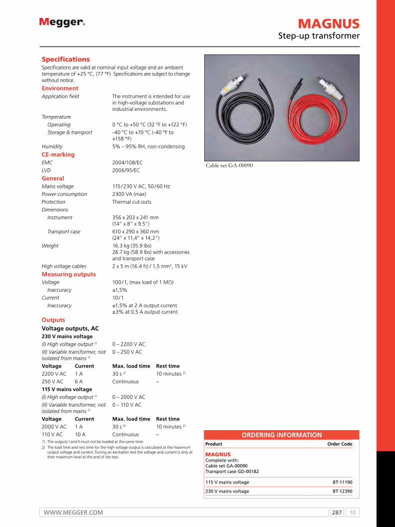
287 10WWW.mEggER.com
Specifications Specifications are valid at nominal input voltage and an ambient temperature of +25 °C, (77 °F). Specifications are subject to change without notice.
EnvironmentApplication field The instrument is intended for use
in high-voltage substations and industrial environments.
Temperature
Operating 0 °C to +50 °C (32 °F to +122 °F)
Storage & transport -40 °C to +70 °C (-40 °F to +158 °F)
Humidity 5% – 95% RH, non-condensing
CE-markingEMC 2004/108/EC
LVD 2006/95/EC
GeneralMains voltage 115 / 230 V AC, 50 / 60 Hz
Power consumption 2300 VA (max)
Protection Thermal cut-outs
Dimensions
Instrument 356 x 203 x 241 mm (14” x 8” x 9.5”)
Transport case 610 x 290 x 360 mm (24” x 11,4” x 14,2”)
Weight 16.3 kg (35.9 lbs) 26.7 kg (58.9 lbs) with accessories and transport case
High voltage cables 2 x 5 m (16.4 ft) / 1,5 mm2, 15 kV
Measuring outputsVoltage 100 / 1, (max load of 1 MΩ)
Inaccuracy ±1,5%
Current 10 / 1
Inaccuracy ±1,5% at 2 A output current ±3% at 0,5 A output current
OutputsVoltage outputs, AC230 V mains voltage(I) High voltage output 1) 0 – 2200 V AC
(II) Variable transformer, not isolated from mains 1)
0 – 250 V AC
Voltage Current Max. load time Rest time2200 V AC 1 A 30 s 2) 10 minutes 2)
250 V AC 6 A Continuous –
115 V mains voltage(I) High voltage output 1) 0 – 2000 V AC
(II) Variable transformer, not isolated from mains 1)
0 – 110 V AC
Voltage Current Max. load time Rest time2000 V AC 1 A 30 s 2) 10 minutes 2)
110 V AC 10 A Continuous –1) The outputs I and II must not be loaded at the same time.2) The load time and rest time for the high voltage output is calculated at the maximum
output voltage and current. During an excitation test the voltage and current is only at their maximum level at the end of the test.
Cable set GA-00090
MAgnUSStep-up transformer
ORDERING INFORMATIONProduct Order Code
MAGNUS complete with:cable set gA-00090Transport case gD-00182
115 V mains voltage BT-11190
230 V mains voltage BT-12390

10 288 T: + 44 (0) 1304 502100 E: [email protected]
PowerDB™ ProAcceptance and maintenance test data management software
PowerDBn Windows-based Pc software available in four versions
n Interfaces to instruments via either Serial RS232, Ethernet, or USB flash drive (depending on instrument)
n Allows user to set up test routines in advance of testing
n Allows analysis, comparison and trending of data
n merge test results between field and office databases
n customize reports for professional data presentation
DescriptionPowerDB is a powerful software package providing data
management for all of your acceptance and maintenance
actitivies. Test results can be imported from various file sources,
captured directly from test instruments, or netered manually.
Data from all sources may be synchronized to your company’s
central database. Result, summary and compliance reports can
be easily generated. PowerDB provides a simple and consistent
user interface to many megger instruments including the
DELTA4000 power factor test set, three-phase TTR, earth testers,
BITE2, Torkel and BVm battery test euipment and 5 and 10 kV
insulation testers.
Full database capabilities
n Test results are brought together into a single database
file for easy retrieval and review.
n An entire organization’s results can be synchronized into a
single database, scalable to microsoft SQL Server.
n Tested assets may b assigned any of six asset categories,
enabling one-step regulatory compliance reporting.
n Easily trend results over time and compare to other similar
assets.
n Track maintenance intervals and generate work orders for
scheduled retests.
n merge results from multiple test instruments with data
imports from other sources to facilitate queries and
sorting.
n maintain test equipment inventory with calibration record.
Optional Add-ons
Data hosting
Data hosting is a service provided by PowerDB where a user’s
master database is sotred in a highly secure data center for
security and backup protection. All test results ad data are
accessible anywhere world-wide through synchronization via
highspeed internet connection. This reduces or eliminates
a user’s computer hardware requirements for storing data,
eliminates the cost of SQL server upgrade and minimizes the
necessity for internal IT expertise. Data hosting requires a one-
time setup fee and a low monthly subscription charge
Microsoft SQL server upgrade
The SQL Server upgrade option functions identically to the
Access version but supports larger databases and provides a
substantial performance increase. PowerDB can seamlessly
interact with Access field databases and SQL master data-
bases.
On site training
A two day training course can be provided at your facility.
Training includes data entry, trending, report generation,
data synchronization and forms design.
CMMS integration
For a flat fee, a PowerDB programmer will aid you in
integrating a data exchange service between PowerDB and
your cmmS system (or any other system). This service includes
up to one week of on-site integration.

289 10WWW.mEggER.com
COMPARISOn gUIDe PowerDB Version
ONBOARD LITE ADVANCED PRO
Runs in a hardened embedded environment n
Navigate with arrow and enter keys (no mouse) n
Manage data files with internal drive and USB drive n
Uses a subset of PowerDB Pro forms applicable to your instrument n n
Files can import into PowerDB Pro n n n
Relay/Breaker/Recloser curve library n n n n
Completed forms are saved as files to your computer n n n n
Associates current test data with historical results n n n n
Control Megger instruments and download test data n n n
Control non-Megger instruments n n
280+ industry standard test forms are provided n n
Advanced relay form n n
Trend historical results for asset for predictive failure analysis n n
Trend historical results for asset against other similar assets n
Database functionality to manage data for all electrical equipment n
One step report generation n
Summarize noted comments and/or deficiencies n
Trigger work order and maintenance schedules n
Synchronize results from field to master database n
Synchronize results with other testers n
Form editor allows test sheets to be created or customized n
Import data from other software packages n
Maintain calibration data for test instruments n
Product Order Code
PowerDB Pro software – 1st copy DB1001
PowerDB Pro software – 1st copy w/USB DB1001S
PowerDB Pro software – 2-5 each copy DB1002
PowerDB Pro software – 2-5 each copy w/USB DB1002S
PowerDB Pro software – 6+ each copy DB1003
PowerDB Pro software – 6+ each copy w/USB DB1003S
PowerDB Pro SQL server version DB1005
ORDeRIng InFORMATIOn
Product Order Code
PowerDB Pro custom forms – per page DB2001
PowerDB Pro cmmS integration DB2002
PowerDB Software training DB3000
PowerDB Advanced software DB1011
ReCOMMenDeD PC SySTeM ReQUIReMenTSWindows® 7/XP/Vista. 2 GHz PC with 2 GB RAM
PowerDB is a trademark of PowerDB, Inc., a subsidiary of Megger
PowerDB™ ProAcceptance and maintenance test data management software

11 290 T: + 44 (0) 1304 502100 E: [email protected]
Selection guide ......................................................................................... 291Technical information ................................................................................ 292E-Z Test™ 99800 meter test jacks ............................................................. 293PA2505K .................................................................................................. 294Phazer™ ................................................................................................... 295
With the testing requirements of today’s advanced systems, it is essential to take advantage of the new technological features of the watthour meter test equipment. No matter what size your operation, you will find that Megger provides testing equipment for all of your watthour meter testing needs. Our testing equipment ranges from portable meter testers to advanced test systems incorporating digital signal processing-based technology.
Watthour Test
11

291 11WWW.mEggER.com
SELECTION GUIDE
E-Z Test™99800
PA2505K Phazer
Single phase n n
Polyphase n n
Three phase n

11 292 T: + 44 (0) 1304 502100 E: [email protected]
Watthour meter test equipment
The kilowatthour meterAn electrical utility has the responsibility to provide electrical service
to a defined geographic area. In return, utilities expect to be fairly
reimbursed for this service. To do this on an equitable basis, they
utilize the electric meter, a device that measures customer usage in
kilowatt hours. Therefore, the kilowatthour meter is considered to
be the “cash register” for the utility. The kilowatthour meter must
accurately measure voltage, current and power factor continuously
over a period of time to arrive at kilowatthours.
Kilowatthours = Watts x Hours / 1000
The kilowatthour meter must register one kilowatthour whether
the customer uses a 1000-watt electric heater for one hour or uses
a 100-watt light bulb for ten hours. We will describe here now the
various components of a kilowatthour meter and the way they work
to measure customer consumption so accurately.
Potential coil To measure voltage or potential, a coil is used which is made up
of many turns of fine wire. This coil is inductive by nature and this,
together with its physical placement within the meter, produces a
lag or delay of approximately 90° between the potential coil flux
and the line voltage and current coil flux.
The potential coil is connected in parallel across the load just as a
voltmeter would be to read volts. Instead of utilizing an indicating
pointer, however, the potential coil measures voltage by producing
a magnetic field proportional to the applied voltage. That is, the
higher the voltage, the stronger the field.
This field acts upon the meter disk, which is a closed loop, by
inducing an emf (electromotive force) within it, which in turn causes
current to flow within the disk. Because these currents flow in a
circular path, they are called eddy currents.
While invisible to the eye, eddy currents are evident as a slight
vibration of the disk whose effect can be felt by lightly touching the
disk while the potential coil is energized and no current is flowing
through the meter.
As the sine wave of the voltage in the potential coil rises from zero
to plus, back to zero, then to minus, and finally back to zero again,
first a north and then a south pole is created by the potential coil
flux. These poles are delayed, however, by the 90° lag, or one-
quarter of a cycle, inherent in the potential coil. As similar north and
south poles are created by the current coil flux, the poles of the two
interact either to attract or repel each other so that the meter disk is
always driven in a counterclockwise direction.
Without the 90° or quarter-cycle displacement, potential coil
and current coil fluxes would arrive at north and south poles
simultaneously. Because like poles repel, the disk would first try to
go counterclockwise, then clockwise as the current and potential
coil fluxes acted upon each other. The net result would be zero
motion.
Current coilsA current coil must produce a flux field whose strength is
proportional to amperes drawn by the customer’s load. The wire
used is large because in self-contained meters, the current coil itself
will be carrying all of the customer’s loads of up to 200 or even
320 amperes (as in the newest extended-range meters) without
overheating. The current coil is in series with the customer load just
as an ammeter would be in taking ampere readings.
Because only a few turns of large wire are in a current coil, and very
little inductive reactance is present, the current in the coil is in phase
with the load current and line voltage. The current coils are wound
around, but insulated from, the lower portion of the laminated
frame, and its flux field produces eddy currents within the disk.
Unlike the potential coil, however, they can neither be seen nor felt.
Retarding magnetRetarding magnets are permanent magnets arranged one on top
and one on the bottom of the air gap so that the disk has to move
between them. The flux from the magnets acts upon the moving
disk by inducing a voltage within it. Because the disk is a closed
loop, eddy currents are created. These currents in turn act against
the magnetic flux of the potential and current coils to create a
negative torque, or braking action, to movement of the disk.
The faster the disk spins, the more intense the braking action
or negative torque tends to be. This phenomenon can be
demonstrated by turning the disk in a meter having no potential
nor current flowing. Using your finger, turn the disk in a
counterclockwise direction very slowly. You will feel very little
resistance to your motion. Now try to spin the disk rapidly, and you
will feel the increase in resistance.
What happens to the meter in actual operation is that as load
increases, the disk speeds up. If no retarding magnet were present,
the disk would accelerate to a point restricted only by line voltage
frequency and friction.
With the magnet present, the meter does accelerate, but only to
a point where its increase in speed is balanced by the additional
negative torque created by the retarding magnet. Thus the speed
of the disk is at a velocity that represents a measured load, or
watthours.

293 11WWW.mEggER.com
E-Z Test™ 99800 meter test jacks
E-Z TestTm 99800 Series
n Industry standard
n Unique, simplified connection system
n Tough, glass-impregnated polycarbonate
DescriptionThe 99800 Series E-Z TestTm meter Test Jacks are designed to
increase safety and to simplify testing of socket-type watthour
meters. They feature dead-front construction and a unique,
simplified connection system. Four types are available for field
testing of virtually all commonly used socket-type meters.
molded from a tough, glass-impregnated polycarbonate,
E-Z Test meter Test Jacks will withstand the rigors of daily
field use. Time-proven, lever-actuate cams are used to firmly
connect the meter blades to the test jack. A husky bypass bus
is incorporated to handle customer loads, even at extended
range meter installations that use the new 320-ampere,
self-contained meters.
SpEcificaTionS anD oRDERinG infoRMaTion
Weight: 2.18 kg (4 lb, 13 oz) Dimensions: 206 H x 172 W x 143 D mm (8.125 H x 6.75 W x 5.625 D in.)
foR TESTinG THESE METERS form no. cat. no.
Single-phase, two-wire self-contained 1S 99805A
Single-phase, three-wire self-contained 2S 99805A
Transformer-rated, two-wire 3S 99805A
Transformer-rated, three-wire 4S 99805A
combination two- and three-wire network 19S, 20S, 21S 99805A
Two-stator, three-wire network 12S, 25S 99805A
Single-stator, three-wire network 23S 99805A
Single-stator network 22S 99805A
Weight: 2.24 kg (4 lb, 15 oz) Dimensions: 206 H x 172 W x 143 D mm (8.125 H x 6.75 W x 5.625 D in.)
foR TESTinG THESE SEVEn-TERMinaL, SELf-conTainED METERS form no.600 V Max.
cat. no.
Weight: 2.32 kg (5 lb, 2 oz) Dimensions: 206 H x 172 W x 143 D mm (8.125 H x 6.75 W x 5.625 D in.)
Two-stator, three-phase, four-wire wye 14S 99806A
Two-stator, three-phase, four-wire delta 15S 99806A
Three-stator, three-phase, four-wire wye 16S 99806A
Three-stator, three-phase, four-wire delta 17S 99806A
foR TESTinG THESE 13-TERMinaL, TRanSfoRMER-RaTED METERS form no.600 V Max.
cat. no.
Weight: 2.32 kg (5 lb, 2 oz) Dimensions: 206 H x 172 W x 143 D mm (8.125 H x 6.75 W x 5.625 D in.)
Two-stator, three-phase, four-wire wye 6S 99807A
Two-stator, three-phase, four-wire delta 8S 99807A
Three-stator, three-phase, four-wire wye 9S, 10S 99807A
Three-stator, three-phase, four-wire delta 11S 99807A
foR TESTinG THESE EiGHT-TERMinaL METERS form no.600 V Max.
cat. no.
Two-stator, three-phase, three-wire transformer-rated 5S 99808A
Two-stator, three-phase, three-wire self-contained 13S 99808A
Two-stator, two-phase, three- or four-wire transformer-rated 5S 99808A
Two-stator, two-phase, three- or four-wire self-contained 13S 99808A

11 294 T: + 44 (0) 1304 502100 E: [email protected]
SPECIFICATIONS
PA2505KPhantom load
pa2505Kn Full-scale range simultaneously selected by
current-range selector switch
n Eliminate need to change leads
n Selectable 50% or 100% power factor
n Test single or polyphase watthour meters
n New compact, heavy-duty metal carrying case
DescriptionThe rugged PA2505K phantom load operates from a single-
phase source and is designed for field-testing single-phase and
polyphase watthour meters at 50 and 100% power factor.
This unit utilizes a heavy-duty selector switch in conjunction
with a variable autotransformer to provide continuous
adjustment of the load current — a valuable feature that
permits close control of the output for different load circuit
impedances or in the event of variations in the source voltage.
The unit is rated for continuous duty with forced-air cooling
provided by a built-in fan. Primary and secondary test leads
are furnished as standard equipment.
PA2505K is provided in a compact, heavy-duty metal, two-
compartment carrying case. The case features a soft grip
handle and ample space for reference standard and test leads.
inpuT
Primary Voltages (specify one group)
69/120/240/277/480 V, 1φ, 50/60 Hz oR 73/127/220/380/415 V, 1φ, 50/60 Hz fused input circuit
ouTpuT
current Ranges (switch-selected)
Full Load 0 to 2.5/5/15/50 A at 50% oR 100% pf
Light Load 0 to 0.25/0.5/1.5/5 A at 100% pf
current control
A variable autotransformer provides continuous control of the output load current from zero to the maximum of each range.
Ammeter circuit
A 89-mm (3.5-in.) ammeter with knife-edge pointer and ±5% full-scale accuracy indicates output load current.
output current connections
Five output terminals are provided to eliminate the need to change lead connections between the phantom load and the reference watthour standard. Four of the output terminals (50, 15, 5 and 1.5 A) are permanently connected to the corresponding input terminals of the reference standard, and the meter under test is then connected in series with the remaining + terminal of the phantom load and the + terminal of the reference standard.
Power Factor
Power factor is maintained above 97% at 100% setting and between 43% and 57% at 50% setting.
Leads
Extra-flexible current and potential test leads and convenient terminals are provided. Leads supplied include those for connecting a reference standard.
Dimensions519 W x 206 D x 295 H mm (20.4 W x 8.1 D x 11.6 H in.)
Weight 13.3 kg (29.2 lb)
SpEcificaTionS
oRDERinG infoRMaTionproduct order code
Phantom Load with carrying case PA-2505K-69
Phantom Load with carrying case PA-2505K-73
Included accessories
Accessory leads
current, 3 m (10 ft), black [1] FL508
current, 3 m (10 ft), red [1] FL509
current, 0.6 m (2 ft) [2] FL510
Voltage, 0.6 m (2 ft) [2] FL511
Remote reset switch 1.8 m (6 ft) [1] Rm-1S
product order code
Fuses
0.75 A, 600 V, KTK [2] 2837
3 A, 250 V, mDA [5] 951
Instruction manual [1] 5516
optional accessories
mA-10-01 etc, reference standards. See megger mA-10 datasheet.

295 11WWW.mEggER.com
PHAZER®
Watthour meter test & calibration system
pHaZERn Now tests watthour meters with installed Turtle® made
by Hunt Technologies®. No need to take the Turtle® out of operation
n For testing socket-mounted meters as well as panel-mounted and bottom-connected meters
n True three-phase and single-phase testing capabilities
n Fully automatic operation
n 32-bit operating software - use with Windows® 95, 98, 2000, mE, NT 4.0 and XP
n State-of-the-art optical sensing system
DescriptionThe PHAZER family of watthour meter test sets are true three-
phase, fully automatic systems capable of testing virtually all
types of ANSI socket- mounted and bottom-connected single-
and three-phase (three and four wire) electricity meters.
The PHAZER family consists of specific models for testing
socket-mounted meters and specific models for testing panel-
mounted and bottom-connected meters.
the PHAZER Watthour meter Test Set easily tests any meter
with an installed Turtle® made by Hunt Technologies®.
Therefore, there is no need to take the Turtle® out of
operation.
PHAZER models for testing panel-mounted and bottom-
connected meters (T20 & T120), feature current and voltage
output binding posts for connections to the panel-mounted
meter without disturbing the meter installation.
input120 V or 240 V ±10%, 50 or 60 Hz, 750 VA
output
The solid-state voltage and current amplifiers are regulated to their programmed values. The operator will be warned if the amplifier output distorts excessively.
Voltage Amplifier Regulation ±1% @ 10 to 100% of range
current Amplifier Regulation±1% or ±5 mA whichever is greater @ 10 to 100% of range
current and Voltage Distortion ±0.5% THD
Measurement Type System accuracy (20-25 °c)
Watt-hour, VA-hour @ 1.0 pf ±0.05% (±0.02% typical)
Watt-hour, VA @ 0.5 pf ±0.10% (±0.03% typical)
Q-hour @ 1.0 pf ±0.10% (±0.03% typical)
Q-hour @ 0.5 pf ±0.05% (±0.02% typical)
VAR @ 0.0 pf ±0.05% (±0.02% typical)
VAR-hour @ 0.866 pf ±0.10% (±0.03% typical)
programmable current
Three isolated, independent floating currents, 0 to 120 A or 0 to 20 A, depending on the model selected, each programmable with a resolution of 0.01 A
programmable Voltage
Three independent, wye-connected potentials, 0 to 600 Vac, each programmable with a resolution of 0.1 V
programmable phase
Each of the three current and voltage channels is programmable for 0 to 360°, with a resolution of 0.1°. Phase accuracy at the meter will be within ±1° or ±1.5° at currents below 0.2 A
optics
Adjustable sensitivity, modulated visible light output, with a 10-segment bar-graph display of reflected intensity. Capable of reflect mode, LCD, LED and infrared detection.
accuracyError increases with temperature 20 ppm/C°
pulse inputsPulse initiator inputs accommodate meters with up to eight separate KYZ outputs.
Reference Standard
A state-of-the-art, three-phase sampling energy standard that incorporates 16-bit A/D converters to achieve very high accuracy is used. Meets ANSI C12.1 performance requirements.
protective circuits
Each system monitors itself for over-temperature, overcurrent and harmonic distortion. Open current or shorted voltage coils result in amplifier shutdown and warning to the operator.
SpEcificaTionS

11 296 T: + 44 (0) 1304 502100 E: [email protected]
Specifications continued
computer/controller
The controller may be ordered from Megger with a choice of three difference configurations:• Standard Controller • Deluxe Controller • Notebook Controller
Minimum specification of the supplied computer are: 600 Mhz Pentium, 32 megabytes of RAM, 810-megabyte hard disk, SVGA monitor, 800 to 1600 dpi resolution, and Microsoft Windows® 95, 98, 2000, ME, NT or XP. note: controller specifications are based on current available hardware.
External connections
A 9-pin female serial interface located on the back panel for connection to the computer. A BNC jack on the front panel for pulse input from an external reference standard. This is used during calibration or reference tests. Three banana jack receptacles and a 25-pin connector for use with KYZ pulse initiator signals are included on the front panel. A 9-pin serial interface located on the back panel for connection of a bar code reader.
Environment
operating0 °C to 45 °C (32 °F to 112 °F), 5 °F to 90% non-condensing RH
Storage -20 °C to +50 °C (-4 °F to +122 °F)
Meter Test Socket
For PHAZER models that test socket-mounted meters, the meter test socket is an electrically operated solenoid with a manual switch control that opens and closes the socket. The socket will remain closed upon power failure. The meter test socket will test the following meter forms:
1 through 6 8 through 17 19 through 23 25, 26, 29, 35, 36 and 45
The built-in socket accepts all self-contained S-Base meters. Optional adapters are available for A-Base and K-Base style meters.
DiMEnSionS anD WEiGHT PHAZER moDELS FoR TESTINg SocKET-moUNTED mETERS:
pHaZER J120 Dimensions
508 H x 560 W x 445 D mm (20 H x 22 W x 17.5 D in.)
Weight 61.4 kg (135.2 lbs)
PHAZER moDELS FoR TESTINg PANEL-moUNTED AND boTTom-coNNEcTED mETERS:
pHaZER T120 and T20Dimensions
475 H x 540 W x 349 D mm(18.7 H x 21.3 W x 13.7 D in. )
Weight 51 kg (112.2 lb)
opTionaL aDapTERS
universal a-base adapter
Megger’s Universal A-base adapter permits the PHAZER systems constructed with Megger’s automated jaw assembly to test virtually all A-base watthour meters. This allows the system additional flexibility when there is the need to test both S-base and A-base watthour meters.
RegulatoryCE marked. Including but not limited to: IEC 61326-1, EN 50081-1, EN 50082-1.
K-base adapter
Megger offers two types of K-base adapters, single and three-phase models. The K-base adapter allows PHAZER systems constructed with Megger’s automated jaw assembly to test K-base style watthour meters. This allows the system additional flexibility when there is the need to test both S-base and K-base watthour meters.
PHAZER®
Watthour meter test & calibration system

297 11WWW.mEggER.com
SPECIFICATIONS oRDERinG infoRMaTionproduct order code
pHaZER models for testing socket-mounted meters
120 V, 60 Hz PZR-J120-160
120 V, 50 Hz PZR-J120-150
240 V, 50 Hz PZR-J120-250
240 V, 60 Hz PZR-J120-260
120 V, 60 Hz (canada) PZRc-J120-160
Included accessories
RS-232 serial cable, 9-pin 16350
calibration input coaxial cable, 1 m 6593
Input line cord 6828
Instruction manual 750001
Fuse 7A 250 V mDL-7 (2) [115 V systems only] 11848
Fuse 5A 250 V mDA-5 (2) [230 V systems only] 952
PHAZER software 544049
optional accessories
Standard controller 16517-X_
Deluxe controller 16517-X_
Notebook controller 16517-X_
bar code scanner 17293-1
calibration adapter 50631
A-base adapter, quick connect 50916
K-base adapter, single-phase 16412
K-base adapter, 3-phase 16411
7S adapter 17000
24S adapter 17001
product order code
pHaZER models for testing panel-mounted and bottom-connected meters 20 ampere model
115 V, 60 Hz PZR-T20-160
240 V, 50 Hz PZR-T20-250
120 ampere model
115 V, 60 Hz PZR-T120-160
240 V, 50 Hz PZR-T120-250
Included accessories
RS-232 serial cable, 9-pin 16350
Roc interconnect cable, 9-pin 15763
calibration input coaxial cable, 1 m 6593
Input line cord 6828
Instruction manual 750005
Fuse 7 A 250 V mDL-7 (2) [115 V systems only] 11848
Fuse 5 A 250 V mDA-5 (2) [230 V systems only] 952
PHAZER software 20 ampere model 544049
Voltage leads, 3.6 m (12 ft) 50254
current leads, 3.6 m (12 ft) 12 ft black (3) 50691
current leads, 3.6 m (12 ft) Red (3) 120 ampere model
50692
Voltage leads, 4/c 1.8 m (6 ft) (1) 50252
current leads, 0.6 m (2 ft) black (3) 50256
current leads, 0.6 m (2 ft) Red (3) 50257
optional accessories
IEc meter Test Station c/w 30 in. current leads 50362
Transport case for model J120 51527
Transport case for models T120 or T20 50989
bar code scanner 17293-1
Standard controller 16517-X_
Deluxe controller 16517-X_
Notebook controller 16517-X_
important notes A computer is NoT INcLUDED when ordering any PHAZER model. The computer must be ordered separately.
To print test results microsoft Access is required.
PHAZER®
Watthour meter test & calibration system

12 298 T: + 44 (0) 1304 502100 E: [email protected]
Selection guide ......................................................................................... 299PFL22M1500 portable cable fault location and high voltage test system .... 300 MTDR300 three phase time domain reflectometer .................................... 302 L1050 portable locator .............................................................................. 304 L1070/1071 portable locator ..................................................................... 305 656902 Split-box pipe and cable locator ................................................... 306
Power cable fault locating and testing takes on a whole new dimension with the modular cable fault locating concept from Megger. We have geared our development to the industry requirements for a more tempered fault locating method and have developed more sophisticated methods that reduce the stress on insulation systems.
Power cabletest
12a

299 12WWW.mEggER.com
SELECTION GUIDE
n feature £ option PFL22M1500
MTDR300
L1050 L1070/1071
SPLIT-BOX PIPE
Van mounted cable fault equipment
Engerised and de-engerised cable locator n
Portable locator n n n n n
Single phase time domain reflectometer n
8/16 kV, 1500 joules surge n
8/16/34 kV, 1500 joules surge
8/16/34 kV, 2000 joules surge
4 kV range £
Arc reflection method n n
Arc reflection plus n
Impulse current n n
Voltage decay £
Integrated TDR n
Integrated and redesigned TDR n
DC testing up to 40 kV n
Proof/burn up to 34 kV n
Proof/burn up to 20 kV n
IP54 with top cover closed n n
Fault detection greater than 50 mtr. n n
Ambient noise reduction headphones
Acoustic signal level indicator n n n
Background interference elimination via selectable acoustic frequency band
n n n
Multiple frequencies n n
Transmits AF or RF signals or both simultaneously n n
Peak and null detection n n
Passive 50/60 Hz n n
Measures current flow in buried conductors n n
Transmitter variable output power levels n n
Push-button depth measurements up to 5 m n
Conductive or inductive tracing n n n
Two channel receiver n

12 300 T: + 44 (0) 1304 502100 E: [email protected]
PFL22M1500n Portable, rugged fault locating systems
n HV insulation testing to 20 kV
n Proof/burn up to 20 kV, 115 mA
n 8/16 kV, 1500 Joules surge output
n Arc reflection method
n Arc reflection plus
DescriptionThe PFL22m1500 power cable fault locator is designed to
provide quick, effective, accurate and safe fault location,
thereby reducing system outages and minutes lost.
The instrument comes in a rugged yet portable enclosure. Its
IP64 rating makes it suitable for use in even environmentally
hostile conditions.
All systems offer the facility to undertake cable testing:
cable and fault diagnosis, pre-location of cable faults, fault
conditioning, and pinpoint fault location using acoustic
methods.
PFL22M1500 Portable cable fault location and high voltage test system
Testing
output0 - 20 kV (negative with regard to earth)0 – 10 kV, 115 mA constant0 – 20 kV, 58 mA constant
Resolution 1 mA
Trip Adjustable current trip
metering Analogue metering of current and voltage
Pre-location low voltage
MTDR100
Range 50 m – 55 km (164 ft - 180,446 ft)
Pulse width50, 100, 200, 500 ns, 1, 2,5,10 µs, and auto
Pulse ampltude 25 V into 50 Ω
Sampling rate 100 MHz
Timbase accuracy 200 ppm
Resolution (Vp=55% 0.82 m (2.8 ft)
Display26.4 mm (10.4 in.), full XGA1024 x 768 colour display
cursors Dual independent control
gain 60 dB range in 5 dB steps
Input Impedance 50 Ω
Inputs 1 x TDR/ARC, 1 x current impulse
Ports 1 x printer/USB memory device
Software CAS1 (cable analysis software)
High voltage pre-location
Arc reflection 0-8 and 0-16 kV, 1500 Joule
Digital Arc reflection 0-8 and 0-16 kV, 1500 Joule
Arc reflection plus0-8 and 0-16 kV, 1500 Joule1024-16 traces dependent on range
Differential Arc reflection 0-8 and 0-16 kV, 1500 Joule
Impulse current 0-8 and 0-16 kV, 1500 Joule
Fault conditioning
Proof/burn0-20 kV 58 mA0-10 kV 115 mA
Pinpoint fault location
Surge 0 – 8 and 0-16 kV, @ 1550 Joule
Impulse sequenceAdjustable 5 - 30 seconds Single shot
Cables
HVDetachable 15 m (25 ft) 1-phase flexiablesheilded cable with HV croc clips
Input/supply 7.5 m (15 ft) 8 mm2 input cable
Earth15 m (25 ft) 8 mm2 flexible earth cable with vice grips
Safety
Universal AVSm 2 ranges108 - 132 V ac and 208 - 265 V ac 47 - 63 Hz
SPECIFICATIONS
301 12WWW.mEggER.com
SPECIFICATIONS
ORDERING INFORMATIONProduct Order Code
20 kV dc. 8/16 kV @ 1550 Joule surge PFL22m1500-EN
As above but including 12 V inverterPFL22m1500-
INV-EN
Included accessories
High voltage shielded output cable 15 m including mc terminations with HV clamps
1001-123
Supply cable, 7.5 m (23 ft) 17032
Flexible ground cable, 15 m (50 ft) 19265-15
Interlock shorting plug 10226-1
cable bag 2001-813
Instruction manual AVTmPFL22
Software cAS-1
Product Order Code
optional accessories
HV vice grips 18944-2
120 V battery trolley mPS120
230 V battery trolley mPS230
PFL20m transit case 2001-289
Stand alone battery supply 100-690
Accoustic/electromagnetic receiver mPP2000
Stand alone cable reel assembly cBL100HV
NB. Refer to factory for full list of cable reel assemblies
PFL22M1500Portable cable fault location and high voltage test system
Specifications continued
Environmental
operating temperature -20 °C to +50 °C (-4 °F to 122 °F)
Storage temperature -20 °C to +55 °C (-4 °F to 131 °F)
Elevation1600 m (Derate voltages at higher altitudes)
Humidity 5 to 95% RH non-condensing
Supply 108 -135 V and 210 - 265 V ac (50/60 Hz)
Ingress protection IP64 (with top/back flaps closed)
Mechanical data
Dimensions (H x W x D)965 mm x 536 mm x 503 mm(3 ft x 1.75 ft x 1.65 ft)
Weight 131 kg (290 lb)

12 302 T: + 44 (0) 1304 502100 E: [email protected]
MTDR300Three phase time domain reflectometer
MTDR300n 3-phase TDR.
n Battery and mains operation.
n Range >55km/34miles (TDR).
n Range >220km/137miles (Transient).
n Auto-Ranging “Find end of cable”.
n Auto-Fault Find “cursor to Fault”.
DescriptionThe mTDR300 is a 3-phase Time Domain Reflectometer
(TDR) designed to provide quick, effective, accurate and safe
prelocation of cable faults in electrical networks.
operation of the instrument is via a single jog dial and
intuitive menu system. The large colour display further
enhances operator comfort and aids rapid and accurate fault
prelocation.
The mTDR300 can be powered from its internal rechargeable
battery or mains power. It’s housed in a rugged, robust, field
proven case making it suitable for use in hostile or challenging
environments.
By combining the mTDR300 with an impulse generator
(thumper) and arc reflection filter, several methods of high
voltage fault prelocation are possible.
The cAS-1 stand-alone software package is supplied with all
mTDR300’s. This package allows the download (and upload)
of saved traces for future analysis. It is also an ideal training
package, as it contains all features of the mTDR itself.
FeaTuRes anD BeneFiTs
n 3-phase TDR operation
n Single Jog Dial operation
n Intuitive “operator Friendly” menu system
n Auto-ranging “find end of cable”
n Auto-fault find “cursor to fault”
n TDR range up to 55km/34miles
n Transient range up to 220km/137miles
n multiple Fault Location Techniques
n 3-phase Pulse Echo
n Arc Reflection
n Arc Reflection Plus
n Differential Arc Reflection
n Impulse current (IcE)Voltage Decay
n Battery or mains operated.
n Battery Low and charge Indicators
n Robust, Rugged construction
303 12WWW.mEggER.com
MTDR300Three phase time domain reflectometer
modes
3-phase Pulse Echo; Arc Reflection; Arc Reflection Plus (ARP); Differential Arc Reflection (DART); Impulse Current (ICE); Voltage Decay
Range
AUTO & 10-ranges100m - 55km (328ft - 34miles) - TDR100m - 220km (328ft - 37miles) - Transient
output pulse widthsAUTO with Range50ns, 100ns, 200ns, 500ns, 1µs , 2µs, 5µs,10µs
output pulse amplitude 25 V into 50 Ω
Sampling rate 100 MHz
Timebase accuracy 200 ppm
Resolution (Vp=55%): 2.7ft (0.82 m)
Display10.4in (26.4 mm), full XGA, 1024 X 768 colour
cursors Dual with independent control
gain 60 dB range in 5 dB Steps
Input Impedance 50 Ω 3 x TDR1 x Arc Reflection / Transient methods
Ports 1 x USB
Software CAS-1 (Cable analysis software)
Supply Mains: 100 to 240 VAC, 45 to 65 Hz
Battery14.4V NiMh Battery Approx. 2hrs operation on full chargeApprox. 2hrs recharge time
Environmental
operating temperature -20 ºC to +50 ºC (-4 °F to +122 °F)
Humidity 95% RH non-condensing
Mechanical data
Dimensions305 mm x 194 mm x 360 mm (12 in. x 7.6 in x 14.2 in.)
Weight 6.7 kg (14.7 lb)
SPECIFICATIONS
ORDERING INFORMATIONProduct Order Code
mDTR 3 phase TDR mTDR300
Included accessories
Accessory pouch 6320-244
Power supply cables
1 x USA 17032-4
! x ScHUKo 17032-13
1 x UK 17032-12
1 x International 17032-5
coaxial cable 10ft / 3 m (3 ea) 19907-11
BNC (F) adaptor (3 ea) 36828
Earth/Ground cable (1 ea) 2003-022
User guide (1) AVTMMTDR300
Cable analysis software CAS-1

12 304 T: + 44 (0) 1304 502100 E: [email protected]
L1050Portable locator
Resonating inductorn multiple frequencies
n Transmits AF or RF signals
n Portable and lightweight
n conductive or inductive tracing
DescriptionThe L1050 portable locator rivals any path locator at any price.
An innovative concept, the receiver is a one-piece design that
is lightweight an highly accurate. The superior filtering of the
L1050 receiver picks up the transmitted signal easily at waist
height, thus eliminating awkward bending.
operating the receiver at multiple frequencies optimises
performance for the specific needs of the user. Low frequency
of 815 Hz provides longer range and reduced errors from
adjacent cables, ideal for electric power services. High 82 kHz
frequency wil path locate past bad telephone bonds, locate
underground stubs and permit inductive locating with either
the optional flexible coupler or direct soil induction.
ApplicationsFlexibility remains the key strength of reaching difficult,
multi-point, grounded utility locating applications. combining
high power at low frequency virtually eliminates the false
coupling into adjacent objects and allows the high transmitter
power to burn a signal past several grounds and into multiple
distributed grounds.
Receiver
operating frequency 815 Hz or 82.135 kHz
Antenna mode Null responding vertical coil
Battery
Battery type 8 x AA size alkaline cells
Battery life 120 hours
Environmental
operating temperature -20 ºC to +55 ºC (-4 °F to +133 °F)
Mechanical data
Dimensions (H x W x L) 7.6 x 7.6 x 33 cm (3 x 3 x 13 in.)
Weight 0.568 kg (1 lbs 4 oz.)
Transmitter
operating frequency 815 Hz or 82.135 kHz
output power815 Hz 100 mW82.315 Hz 100 mW
Directly coupled 100 mWInductively coupled 110 mW
Power
Battery type 8 x D size alkaline cells
Battery life 150 hours
Environmental
operating temperature -20 ºC to +55 ºC (-4 °F to +133 °F)
Mechanical data
Dimensions (H x W x L) 16 x 19 x 43 cm (6.5 x 7.5 x 17 in.)
Weight 2.8 kg. (6 lb 3 oz)
SPECIFICATIONS
ORDERING INFORMATION
Product Order Code
L1050 portable locator 651050
Included accessories
Peaking receiver, transmitter (2 frequencies), red/black cord, batteries and ground rod
Instruction manual
optional accessories
Flexible coupler (inductive coupler) 651056

305 12WWW.mEggER.com
L1072/3/3-10Portable locators
Portable locatorsn multiple location modes
n multiple frequencies
n Pushbutton depth and current indication
n Transmitter variable output power levels
n Powerful 10 W transmitter option
n SoNDE support
DescriptionThe megger portable locators, models L1072, L1073 and
L1073-10, accurately and quickly locate buried cables and
pipes. They are built to a proven design and benefit from
advanced technology making them ideal for today’s
demanding requirements. The transmitter is available with
either disposable or rechargeable batteries.
Suitable for use on long or short ranges, inductive or
conductive, and active or passive, the units deliver quick and
accurate results with a user-friendly interface.
Transmitter
operating frequency82 kHz, 8 kHz, 815 Hz, and BOTH (815 Hz/82 kHz) simultaneously
Load matching Automatic from 5 Ω to 2000 Ω
output power (6 settings)
Battery
L1072 Battery type Standard 1.5 V ‘D’ cells
Battery typeContinuous: 8 to 15 hours depending onload, frequency and power setting.Intermittent: 40 to 60 hours
L1072 Battery type Rechargeable 12 V 7 Ah lead acid
Battery lifeContinuous: 10 to 20 hours depending onload, frequency and power settingIntermittent: 50 to 70 hours depending onload, frequency and power setting
Environmental
operating temperature 15 x 16 x 41 cm (6 x 6.32 x 16 in.)
Mechanical data
Dimensions (H x W x L) 15.2 x 12.7 x 40.6 cm (6.5 x 6.32 x 16 in.)
WeightL1072 - 3.6 kg (8 lbs) with alkaline D cellsL1073 and L1073-10 - 5.7 kg (12.5 lb)with rechargeable batteries
Receiver
operating frequency 815 Hz, 8 kHz, 82 kHz, 50/60~(PASSIVE)
Antenna modeNull responding vertical coilPeak responding horizontal coil
Audio indication Variable pitch response on all frequences
Current measurement
Display indicated relative current simultaneously between any two selected cables for target cable verification in a multi-conductor environment.
Battery
Battery type 6 x 1.5 V C size alkaline
Battery life
Continuous: 40 hoursIntermittent: 82 hoursAuto power shutoff after 10 minutes of nonuse.
Environmental
operating and storage temperature
-20 ºC to +55 ºC (-4 °F to +133 °F)
Mechanical data
Dimensions (H x W x L) 23.8 x 9.3 x 76.9 cm (9.4 x 3.75 x 30.3 in.)
Weight 1.36 kg (3 lb)
SPECIFICATIONS
ORDERING INFORMATIONProduct Order Code
Portable locator, transmitter ‘D’ cell L1072
Portable locator, transmitter rechargeable L1073
10 W portable locator, transmitter rechargeable L1073-10
Included accessories
L1072: Receiver, rechargeable transmitter, red/blackcord, batteries, ground rod, instruction manual andsoft carrying case
L1073/L10730-10 Receiver, rechargeable transmitter,red/black cord, batteries, ground rod, AC charger,instruction manual and soft carrying case
Optional accessories
Folding ground return probe (grounded fault locator) 651075
Flexible coupler (inductive coupler) 651076
DC charger (automotive) used with 651071 651078
4 in. coupler (inductive coupler) 651079
L1072/1073 L1073-10
Frequency Low High Low High
815 Hz 0.2 W 5 W 0.6 W 8 W
8 kHz 0.2 W 5 W 0.6 W 10 W
33 kHz 0.2 W 5 W 0.6 W 10 W
82 kHz 0.2 W 5 W 0.2 W 1 W
Both 815 Hz & 82 kHz 0.6 W 0.6 7W 0.6 W 0.67 W

12 306 T: + 44 (0) 1304 502100 E: [email protected]
656902Split-box pipe and cable locator
Split-box pipe and cable locatorn Energised or de-energised lines tracing
n conductive or inductive coupling
n Peak and null detection capabilities
n Hand-held and lightweight
n Solid construction in a tough, plastic housing
DescriptionThe split-box pipe and cable locator is a hand-held instrument
in the classic ‘split-box’ design, consisting of a transmitter and
a receiver. The instrument traces under-ground conductive
networks such as water and gas mains, telephone, cable TV
and electric power cables. It determines buried lines depth
and oclates underground metallic masses such as valve caps
and manhole covers.
Designed with patented super-inductive technology, the split-
box pipe and cable locator is lightweight, portable and easy
to use. For easy transport, the instrument and accessories are
supplied with a protective tote bag.
ApplicationsTo locate and trace an underground metallic line, the line
is energised with a radio frequency signal generated by the
transmitter and then detected by the receiver. Inductive or
conductive modes of operation are available.
The inductive operational mode does not require direct
mechanical line connection.
The conductive mode of operation requires the line to be
exposed so that a direct connection can be made.
output frequency 126 kHz
Battery type4 each ‘C’ size alkaline for transmitter and receiver
Battery life 50 hours
Audio output Built-in speaker and headphone jack
Sensitivity Manual signal adjust
Environmental
operating temperature -20 ºC to +70 ºC (-5 °F to +158 °F)
Mechanical data
Dimensions (H x W x L)for Receiver and Transmitter
165 x 60 x 215 mm (6.5 x 2.375 x 8.5 in.)
Weight for Receiver and Transmitter
1.1 kg (2.5 lb)
SPECIFICATIONS
ORDERING INFORMATIONProduct Order Code
Spilt-box pipe and cable locator 656902
Included accessories
Batteries (4 ea.)
Protective tote bag
Direct connection cable, 3 ft
ground rod
Instruction manual
optional accessories
Induction lamp 656626
mini headset 656902-4
Large carrying case (holds induction clamp and large direct connection cable)
656902-5
Direct connection cable, 6 ft 656902-6
Receiver carrying strap 656902-7

307 12WWW.mEggER.com

12 308 T: + 44 (0) 1304 502100 E: [email protected]
EZ-THUMP™ portable fualt location system .............................................. 309SFX 5-1000 portable test and fault locating system ................................... 310SFX 8 cable fault locating system .............................................................. 311SFX 15 and 25 mobile cable fault locating system ..................................... 312SFX 32 portable cable test and fault locating system ................................. 313SFX 40 mobile cable testing and fault location system ............................... 314digiPHONE+ surge wave receiver ............................................................... 316ESG NT digital earth fault locator .............................................................. 317HV tester 25 kV portable HV tester ........................................................... 318HV test set 50/80/100 kV portable HV tester for DC voltage testing .......... 319T 99/1 high voltage test unit ..................................................................... 320HPG 70-K high voltage test set ................................................................. 321Easytest 20 kV AC cable tester .................................................................. 322VLF Sinus 34 kV sine wave test system ...................................................... 323VLF CR-28 up to 60 kV portable VLF test systems ...................................... 324Tan delta test attachment integral cable diagnosis system ......................... 326CDS cable diagnostic system ..................................................................... 327CI cable identifier ...................................................................................... 328PIL 8 Phase identification in earthed and short circuited medium voltage cables 330PVS 100 phase verification system ............................................................. 331MFM 10 sheath fault location system ........................................................ 332Teleflex SX portable reflectometer for fault location systems ...................... 333Teleflex VX system reflectometer ............................................................... 334Teleflex LV cable monitor ........................................................................... 335 Teleflex T 3060 single phased power reflectometer ................................... 336 Cable test vans ......................................................................................... 337
The Seba cable test and diagnostics products range cover all cable fault needs. The following provides a brief view of the test solutions available and does not cover the full product offering.
Please contact us to discuss your cable fault and test diagnostic needs.
Seba cable fault location and testing diagnostics
12b

309 12WWW.mEggER.com
EZ-THUMP™ SeriesPortable fault location system
EZ-Thumpn 4 kV or 12 kV output versions available
n Battery and AC line operation
n ARM® prelocation
n Fault pinpointing (Thumping)
n Optional sectionalizing software*
n Automatic end-of-cable and fault locating
DescriptionThe EZ-THUMP4 and EZ-THUMP12 are compact and
lightweight, battery and AC line operated, portable cable
fault location systems. They are designed for quick, effective,
accurate and safe fault locating operations to greatly reduce
system customer outage minutes.
Due to their rugged yet portable enclosure, they are ideally
suited either for use in a “satellite” fault locating concept for
remote areas that may have less frequent faults, when ease of
operation, light weight and economics are important, or for
hard to access inner city locations.
The units require no adjustments and are operated via a
rotary control knob.
The EZT4/12 series offers:
n Arc Reflection Method (ARM®) cable fault prelocation
n 500 Joule pinpoint surge generator
n DC testing for breakdown detection
n Insulation resistance measurement and sheath testing
n A 4 kV or 12 kV version
Testing
Output0 – 4 kV, 35 mA DC (EZ-THUMP4)0 – 12 kV, 12 mA DC (EZ-THUMP12)
Prelocation
TDR
Range: 25,000 ft (7.6 km)Sampling Rate: 100 MhzResolution: 2.5 ft @ 250 ft/ƒs0.8 m @ 80 m/ƒs
Arc reflection 0 – 4 kV or 0 – 12 kV (model dependent)
Pinpoint fault location
Surge0 - 4 kV @ 500 J (EZT4)0 – 12 kV @ 500 J (EZT12)
Impulse sequence 10 seconds, Single shot
Display5.7 in. (14.48 cm) Transflective TFT Color LCD 640 x 480 pixel
Memory 1000 traces
Interface USB port
Cables/terminations
15 ft (4.6 m) HV flexible shielded cable with MC connector and hotline clampHV return with hotline clamp15 ft (4.6 m) ground/earth cable with hotline clamp6 ft (1.8 m) mains supply lead set (US/SCHUKO/UK)
Supply
Battery
Internal 24 V NiMH Battery 5 AH Approx. 30 mins of surge/thumping Approx. 3 hours recharge time 100-240 VAC – 24 VDC charger with connection lead set (US/SCHUKO/UK)
AC line 100 – 230 VAC ±50/60 Hz
SafetyEmergency stopKey-switch InterlockAuto “time out”
Environmental
Operating temperature -4 ° to 122 °F (-20 ° to +50 °C)
Storage temperature -12 ° to 160 °F ) (-25 ° to +70 °C)
IP rating IP54 (with top open)
Weight 71 lbs (32 kgs)
Dimensions 14 x 11 x 21 in. (35.5 x 28 x 53.3 cm)
SPECIFICATIONS

12 310 T: + 44 (0) 1304 502100 E: [email protected]
EZ-THUMP™ SeriesPortable fault location system
ORDERING INFORMATIONProduct Order Code
4-kV Portable fault location system EZT4-wwxxy
12-kV Portable fault location system EZT12-wwxxyz
options (must be defined when ordering):
cable length designator (xx):
15 ft (4.6 m) HV output and ground cables ww = 15
50 ft (15 m) HV output and ground cables ww = 50
cable termination designator (yy):
14 mm male mc with Hotline clamp (NAFTA) xx = T1
14 mm male mc with Vise grip (NAFTA) xx = T2
No terminations (UK) xx = T3
10 mm female mc with battery c clamps (cEE, RoW & cSA)
xx = T4
Sectionalizing designator (y)
With sectionalizing software y = S
Without sectionalizing software y= “leave blank”
Hand cart prep designator (z)
With Hand cart prep z = c
Without Hand cart prep z = “leave blank”
Product Order Code
Included accessories
6 ft (1.8 m) mains supply lead set (US/Schuko/UK) 1002-889
Universal battery charger kit (US/Schuko/UK) 1002-890
Instruction manual AVTmEZT4/12
optional accessories
Hand cart for EZT4/12 895000180110000
15 kV elbow 14 mm female mc connector 865000100100000
25 kV elbow 14 mm female mc connector 865000200100000
35 kV elbow 14 mm female mc connector 865000300100000
Digiphone Plus surge wave receiver 871500500100000
ESg NT digital earth fault locator 871500200200000
Applications
HV TesTing (PRooF/insuLaTion TesTing)Used to test the dielectric strength of a cable and, if the test
fails, to determine the breakdown voltage. For this purpose a
test voltage up to 4 kV or 12 kV (model dependent) is applied
to the cable under test indicating the resistance value.
sHeaTH TesT anD sHeaTH FauLT LocaTion / unsHieLDeD Low VoLTage PoweR caBLe FauLT LocaTingAn intact jacket and sheath of a sold dielectric insulated cable
is required to avoid ingress of water and subsequent cable
faults. With this test, the dielectric strength of the cable jacket
is tested by applying a DC voltage of up to 10 kV to the cable
sheath (concentric neutral).
Sheath fault location requires the additional item ESG NT
Digital ground/ earth fault locator with optional “A” frame.
Accurate location of sheath faults is achieved using the step-
voltage method: as the fault approaches, the step voltage
potential increases, decreasing with reversed polarity after
it passes the fault. The change in polarity allows the fault
to be located precisely. The identical method with the same
equipment can also be used for secondary fault locating on
unshielded low voltage power cables.
FauLT PRe-LocaTionAfter identifying the type of fault, prelocation of the fault
position is determined using ARM®. The fault is stabilized by
creating a temporary “bridge” to ground/earth. During this
condition, a standard TDR measurement is made into what is
basically a short circuit fault.
secTionaLizing (oPTionaL)The sectionalizing mode is used to identify and indicate the
location of transformers in a loop or radial system, locating
the fault between its 2 closest transformers, which identifies
the faulted span.
PinPoinT FauLT LocaTionAccurate pinpoint fault location is achieved using the
“Thunder & Lightning” method whereby the 500 Joule surge
generator (thumper) and an acoustic/electromagnetic receiver
is used.
FeaTuRes anD BeneFiTsThe EZ-THUMP 4/12 series of portable fault locators combine
the following features and benefits in a single device.
n Quick-Step and Expert modes, especially convenient where
operators may not be called upon to use the equipment on
a regular basis
n Automatic fault locating procedure
n Operating of unit via rotary control knob
n Automatic end-of-cable and fault detection
*HDW Electronics, Inc. Patent No. US 6, 683,459 B2
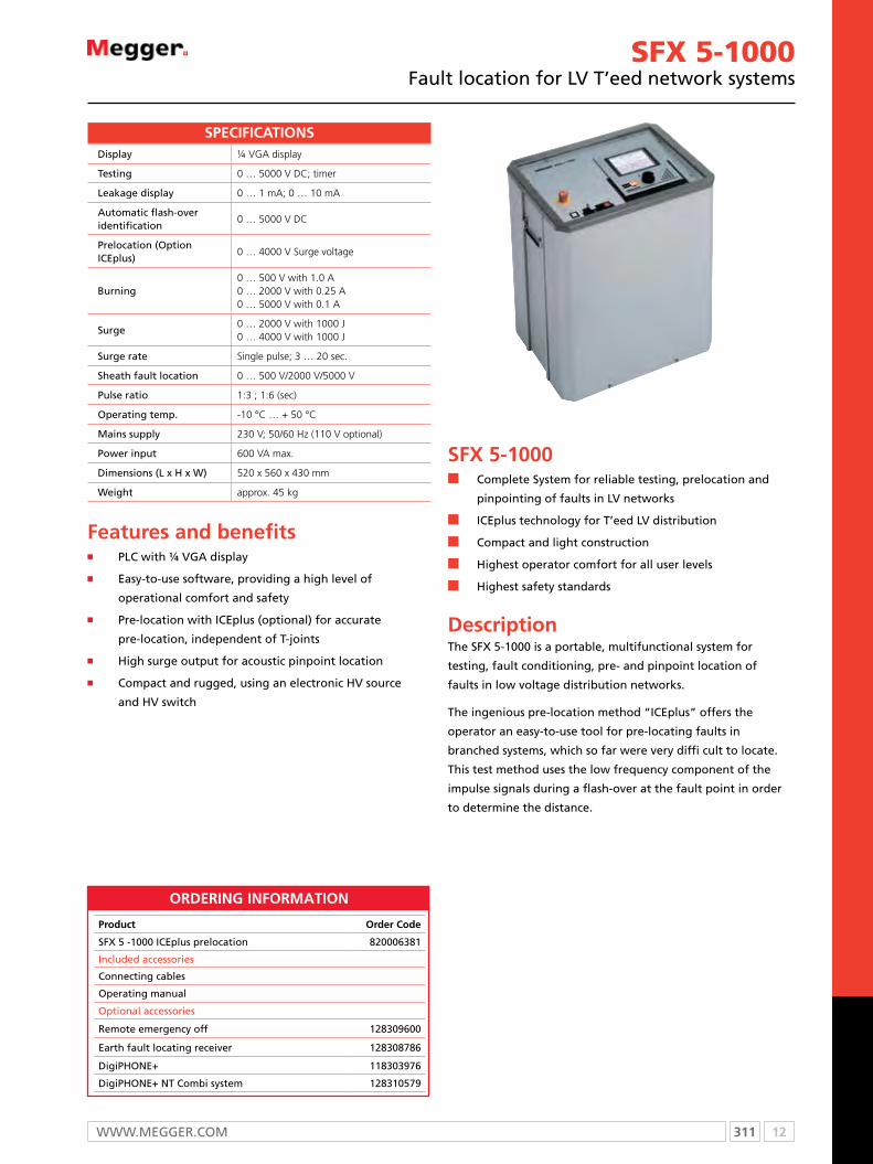
311 12WWW.mEggER.com
SFX 5-1000Fault location for LV T’eed network systems
SFX 5-1000n Complete System for reliable testing, prelocation and
pinpointing of faults in LV networks
n ICEplus technology for T’eed LV distribution
n Compact and light construction
n Highest operator comfort for all user levels
n Highest safety standards
DescriptionThe SFX 5-1000 is a portable, multifunctional system for
testing, fault conditioning, pre- and pinpoint location of
faults in low voltage distribution networks.
The ingenious pre-location method “ICEplus” offers the
operator an easy-to-use tool for pre-locating faults in
branched systems, which so far were very diffi cult to locate.
This test method uses the low frequency component of the
impulse signals during a flash-over at the fault point in order
to determine the distance.
Display ¼ VGA display
Testing 0 … 5000 V DC; timer
Leakage display 0 … 1 mA; 0 … 10 mA
Automatic flash-over identification
0 … 5000 V DC
Prelocation (Option ICEplus)
0 … 4000 V Surge voltage
Burning0 … 500 V with 1.0 A0 … 2000 V with 0.25 A0 … 5000 V with 0.1 A
Surge0 … 2000 V with 1000 J0 … 4000 V with 1000 J
Surge rate Single pulse; 3 … 20 sec.
Sheath fault location 0 … 500 V/2000 V/5000 V
Pulse ratio 1:3 ; 1:6 (sec)
Operating temp. -10 °C … + 50 °C
Mains supply 230 V; 50/60 Hz (110 V optional)
Power input 600 VA max.
Dimensions (L x H x W) 520 x 560 x 430 mm
Weight approx. 45 kg
SPECIFICATIONS
Features and benefits n PLC with ¼ VGA display
n Easy-to-use software, providing a high level of
operational comfort and safety
n Pre-location with ICEplus (optional) for accurate
pre-location, independent of T-joints
n High surge output for acoustic pinpoint location
n Compact and rugged, using an electronic HV source
and HV switch
ORDERING INFORMATION
Product Order Code
SFX 5 -1000 IcEplus prelocation 820006381
Included accessories
connecting cables
operating manual
optional accessories
Remote emergency off 128309600
Earth fault locating receiver 128308786
DigiPHoNE+ 118303976
DigiPHoNE+ NT combi system 128310579

12 312 T: + 44 (0) 1304 502100 E: [email protected]
SFX 8-1000Cable fault locating system
SFX 8-1000n DC-testing up to 8 kV
n Pre-locating
n Burning (fault conditioning) up to 8 kV
n Cable tracing (optional)
n Pin-pointing
n High burn current
DescriptionThe SFX 8-1000 is a mobile and economical fault locating
system, perfectly suitable for low and medium voltage cables
as well as control cables or deep-well-pump cables.
The powerful ARM® (Arc Reflection Method) is used to pre-
locate high resistance faults. Conditioning faults - if necessary
- is possible by short-term burning in all voltage levels.
The Teleflex SX offers convenient operator support with
online help and one-button-operation. It automatically shows
the far end of cable and fault distance in the ARM-Mode.
Even inexperienced users can easily locate faults with the
Teleflex SX. The operator is guided through the fault locating
process.
1000 Joules of surge energy provide the necessary power for
accurately pin-pointing cable faults with the acoustic method.
Big wheels make the unit suitable for easy operation in the
field. The modular set-up allows a flexible constellation of the
SFX 8 to fit individual needs.
Teleflex SX
TDR 20 m … 160 km @ v/2 = 80 m/μs
Transienten 20 m … 160 km
Pulse width 20 ns ... 5 μs
Sampling rate up to 400 MHz
Display10.4” color TFT XGA 1024x768, capacitive Touchscreen
V/2 10 ... 149.9 m/μs
Modes
Symmetricalunsymmetrical reflection measurementDifference measurement/ comparisonAll ARM Arc Reflection methods, ARM Slide, Pro Range,All ICE impulse current decoupling methodsDECAY Travelling wave methodIFL Intermittent Fault LocationArc reflection burning
Memory 4 GB
Interface Ethernet, USB, BNC, CAN (LON optional)
Impedance matching 8 Ω ... 500 Ω, adjustable
Operating temperature -10 °C … + 50 °C
SupplyNiMh-Battery, 110 - 230 V; 50/60 Hz, 12 V DC
Dimensions (W x H x D) 362 x 195 x 306 mm
Weight 6 kg
The Teleflex SX is available as a portable, battery operated stand-alone version or can be integrated in any measuring system with 19” rack mounting.
Surge unit 2/4/8 kV
TestingSurge
0 ... 8 kV0 ... 2 kV; 1000 J0 ... 4 kV; 1000 J0 ... 8 kV; 1000 J
Surge rate2 ... 6 sSingle pulse
Burning up to 1.4 A
Technical data of system
Connecting cable 6 m (standard)
Mains supply 230 V; 50/60 Hz, 2.3 kVA (110 V optional)
Dimensions (W x H x D) 530 x 1390 x 660 mm
Weight approx. 90 kg
SPECIFICATIONS
ORDERING INFORMATION
Product Order Code
SFX unit 2/4/8 kV 820008619
ARm® unit 8 kV
Teleflex
mounting frame on wheels
operating manual
Set of connecting cables
optional adcessories
DigiPHoNE+ 118303976
DigiPHoNE+ NT combi system 128310579
Vehicle installation version without battery, inverter and trolley

313 12WWW.mEggER.com
SFX 15 and 25Mobile, battery operated cable fault locating system
SFX 15 and 25n Testing in low and medium voltage networks
n Easy to use
n Extremely rugged design
n Stand-alone operating
DescriptionThe mobile and battery powered fault locating system is
designed for stand-alone operation. It will provide its full
surge energy for up to 1.5 hours continuously. With 15 kV or
25 kV output voltage these systems are well suited for fault
locating in low and medium voltage distribution networks.
The powerful ARM (Arc Reflection Method) is used for
prelocation of high resistance faults. Low resistance faults can
be located with only the Teleflex SX and without having to
use high voltage methods.
The Teleflex SX offers convenient operator support with
online help and one-button-operation. It automatically shows
the far end of cable and fault distance in the ARM-Mode.
Even inexperienced users can easily locate faults with the
Teleflex SX. The operator is guided through the fault locating
process.
1150 Joules of surge energy provide the necessary power for
accurately pin-pointing cable faults with the acoustic method.
Weatherproof housing and big wheels make the SFX 15 and
25 suitable for easy operation in the field.
Connecting cables are conveniently accessible at the rear of
the unit.
Teleflex SX
TDR 20 m … 160 km @ v/2 = 80 m/μs
Transienten 20 m … 160 km
Pulse width 20 ns ... 5 μs
Sampling rate up to 400 MHz
Display10.4” color TFT XGA 1024x768, capacitive Touchscreen
V/2 10 ... 149.9 m/μs
Modes
Symmetricalunsymmetrical reflection measurementDifference measurement/ comparisonAll ARM Arc Reflection methods, ARM Slide, Pro Range,All ICE impulse current decoupling methodsDECAY Travelling wave methodIFL Intermittent Fault LocationArc reflection burning
Memory 4 GB
Interface Ethernet, USB, BNC, CAN (LON optional)
Impedance matching 8 Ω ... 500 Ω, adjustable
Operating temperature -10 °C … + 50 °C
Supply NiMh-Battery, 110 - 230 V; 50/60 Hz, 12 V DC
Dimensions (W x H x D) 362 x 195 x 306 mm
Weight 6 kg
The Teleflex SX is available as a portable, battery operated stand-alone version or can be integrated in any measuring system with 19” rack mounting.
Weight approx. 110 kg
SFX 25-1150
Test and surge voltage0 ... 12.5 kV; 1150 J0 ... 25 kV; 1150 J
Weight approx. 110 kg
Technical data of system
Surge rate 3 ... 9 s
Battery operation approx. 1.5 h (1150 J)
Mains supply 230 V; 50/60 Hz (110 V optional)
Dimensions (W x H x D) 600 x 1250 x 600 mm
Connecting cable 6 m (standard)
SPECIFICATIONS
ORDERING INFORMATION
Product Order Code
Surgeflex 15-1150 port. Fault location systemSurgeflex unit SPg 15-1150, 7.5/15 kV, 1150 J Teleflex SX, Set of cables, charger
820014810
Surgeflex 25-1150 port. Fault location systemSurgeflex unit SPg 25-1150, 12.5/25 kV, 1150 J Teleflex SX, Set of cables, charger 820019382
optional adcessories
DigiPHoNE+ 118303976
DigiPHoNE+ NT combi system 128310579
Vehicle installation version without battery, inverter and trolley
SFX 15 and 25...also available with T3060 TDR option and optional for vehicle installation. Contact our sales office for more details

12 314 T: + 44 (0) 1304 502100 E: [email protected]
SFX 32n Safe and fast fault location with latest
n TDR technology
n High surge energy for effective pinpoint locating
n Various fault location methods included
DescriptionThe SFX 32 is a mobile system for testing and fault locating on
low and medium voltage cables. The powerful ARM (Arc
Reflection Method) is used for prelocation of high resistance
faults up to 32 kV. Conditioning faults - if necessary - is
possible by short term burning in all voltage levels. Low
resistance faults can be located with only the TDR Teleflex
SX and without having to use high voltage methods.
The Teleflex SX offers convenient operator support with
online help and one-button-operation. It automatically shows
the far end of cable and fault distance in the ARM-Mode.
Even inexperienced users can easily locate faults with the
Teleflex SX. The operator is guided through the fault locating
process.
1750 Joules of surge energy provide the necessary power for
accurately pinpointing cable faults with the acoustic method.
Big wheels make the unit suitable for easy operation in the
field.
Connecting cables for earthing, mains, and HV are conveniently
accessible at the rear of the unit.
SFX 32Portable cable test and fault location system
Teleflex SX
TDR 20 m … 160 km @ v/2 = 80 m/μs
Transienten 20 m … 160 km
Pulse width 20 ns ... 5 μs
Sampling rate up to 400 MHz
Display10.4” color TFT XGA 1024x768, capacitive Touchscreen
V/2 10 ... 149.9 m/μs
Modes
Symmetricalunsymmetrical reflection measurementDifference measurement/ comparisonAll ARM Arc Reflection methods, ARM Slide, Pro Range,All ICE impulse current decoupling methodsDECAY Travelling wave methodIFL Intermittent Fault LocationArc reflection burning
Memory 4 GB
Interface Ethernet, USB, BNC, CAN (LON optional)
Impedance matching 8 Ω ... 500 Ω, adjustable
Operating temperature -10 °C … + 50 °C
SupplyNiMh-Battery, 110 - 230 V; 50/60 Hz, 12 V DC
Dimensions (W x H x D) 362 x 195 x 306 mm
Weight 6 kg
The Teleflex SX is available as a portable, battery operated stand-alone version or can be integrated in any measuring system with 19” rack mounting.
HV Module SFX 32
Testing 0 … 32 kV DC
Surge
0 … 8 kV; 1750 J ( 3500 J Optional) 0 … 16 kV; 1750 J ( 3500 J Optional) 0 … 32 kV; 1750 J ( 3500 J Optional) 0 ... 4 kV, 1200 J (Option)
Surge rate 3 … 10 s, Single pulse
Burning 0 … 32 kV; 160 mA
Sheath fault locating 0 … 5 kV; 160 mA
Technical data of system
Connecting cable 6 m (standard)
Mains supply 230 V; 50/60 Hz, 2 kVA (110 V optional)
Dimensions (W x H x D) 800 x 1280 x 800 mm
Weight Approx. 140 kg
SPECIFICATIONS
ORDERING INFORMATION
Product Order Code
SFX 32; 0 ... 8 / 16 / 32 kV 813372
Teleflex SX
mounting frame on wheels
operating manual
Set of connecting cables
Product Order Code
optional accessories
Surge extension to 3500 J (only for vehicle installation)
820000317
4 kV surging with1200 J 820021358
Surge wave receiver DigiPHoNE+, complete 118303976
Pinpointing receiver DigiPHoNE+, complete 128310579
Earth fault location unit complete 128308786

315 12WWW.mEggER.com
SFX 40Mobile cable testing and fault location system
SFX 40n High surge energy
n Portable and test van installation version
n All HV prelocation methods integrated
n High level of operational comfort and safety
DescriptionThe SFX 40 is a mobile, multifunctional system for testing,
converting, prelocation and pinpointing cable faults in low
and medium voltage networks.
The system is controlled directly via the connected Teleflex SX
reflectometer or the integrated control panel. Depending on
the installation, the HV is controlled either by the network
and HV control integrated in the device or by a separate
HV ON/ OFF box. All functions of the system can be easily
performed using the selector knob.
The software supports easy and clear handling, even for
inexperienced users. At the same time, the highest degree of
safety is guaranteed.
Modes of operationn Insulation test up to 5,000 V
n Dc test up to 40 kV with ramp function, automatic switch-off in case of breakdown and display of break down voltage
n ARm prelocation procedure method, IcE impulse current method and decay voltage decoupling
n Fault conversion / burning with adjustable burning current
n Acoustic pinpointing
n Sheath fault location with step voltage method
Teleflex SX
TDR 20 m … 160 km @ v/2 = 80 m/μs
Transienten 20 m … 160 km
Pulse width 20 ns ... 5 µs
Sampling rate up to 400 MHz
Display10.4" color TFT XGA 1024x768, capacitive Touchscreen
V/2 10 ... 149.9 m/μs
Modes
Symmetrical/unsymmetrical reflection measurementDifference measurement/ comparisonAll ARM Arc Reflection methods, ARM Slide, Pro Range,All ICE impulse current decoupling methodsDECAY travelling wave methodIFL Intermittent Fault LocationArc reflection burning
Memory 4 GB
Interface Ethernet, USB, BNC, CAN (LON optional)
Impedance matching 8 Ω ... 500 Ω, adjustable
Operating temperature -10 °C … + 50 °C
SupplyNiMh-Battery, 110 - 230 V; 50/60 Hz, 12 V DC
Dimensions (W x H x D) 362 x 195 x 306 mm
Weight 10 kg
SFX 40
Display ¼ VGA
Insulation testVoltages 1,000 V and 5,000 Vranges 1 kΩ, 1 MΩ, 100 MΩ
DC testing 0 … 40 kV DC
Leakage current0 … 1/10/100 mA automaticmeasuring area setting
Breakdown detection 0 … 40 kV
Burning 0 … 8 kV; 0.7 A; 0 … 20 kV ; 0.1 A
Upper surge voltages 0 … 12.5 / 25 kV or 0 … 16 / 32 kV
Lower surge voltages(optional)
0 … 4 kV or 0 … 8 kV0 … 3 kV or 0 … 6 kV
Surge energy1,000 J in every range (optionally2,000 J for vehicle installation)
Surge sequence 3 … 10 sec. and single pulse
Sheath fault location 0 … 5 kV and 0 … 10 kV
Cycle intervals DC; 1:3 ; 1:4 ; 1:6 (sec.)
HV prelocation(with optional TDR)
ARM, ICE current decouplingDecay voltage couplingICE Plus option (for 4 and 8 kV)
Operating temperature -10 °C … + 50 °C
Power supply 230 V; 50 / 60 Hz (110 V optional)
Power consumption 1.7 kVA max.
Dimensions (L x W x H) 520 x 430 x 1,050 mm
Weight ca. 116 kg (incl. opt. surge level)
SPECIFICATIONS

12 316 T: + 44 (0) 1304 502100 E: [email protected]
ORDERING INFORMATION
Product Order Code
Special accessories
External emergency stop switch with warning lamp system
DigiPHoNE+ 118303976
DigiPHoNE+ NT combi system 128310579
Short to earth detector EgS 80-2
Teleflex HV Version Version Voltage HV Voltage LV TDR
Yes SFX 40 32 kV 32 Vehicle Installation M 16 / 32; 1000 J 1 4 kV; 1000 J 1 Teleflex VX 1
No SPG 40 25 kV 25Portable with
trolleyP 16 / 32; 2000 J 2 8 kV; 1000 J 2 Teleflex SX 2
12,5 / 25 kV; 1000 J 3 4 / 8 kV; 2000 J 3 T 3060 3
12,5 / 25 kV; 2000 J 4 3 kV; 1000 J 4
6 kV; 1000 J 5
3 / 6 kV; 2000 J 6
No LV 7
Example SFX-40-32-M-2-3-2 represents an
SFX 40-32-M with 4,8,16,32 kV 2000 J and Teleflex SX
oRDeRing conFiguRaTion

317 12WWW.mEggER.com
digiPHONE+n Perfect acoustic quality and noise immunity
n Automatic mute function to protect your ears
n Bright, transflective sun readable display
n Easiest handling with automatic adjustment
n Earphone volume limitation to 84 dB(A)
DescriptionIn most cases surge wave generators are used for pinpointing. These surge wave generators create a loud flashover crack by means of a capacitive discharge at the location of the fault. This is pinpointed precisely using an acoustic pinpointing device such as the digiPHoNE+. To do this, the time difference between the acoustic signal and the electromagnetic impulse of the surge discharge is evaluated. When searching the cable run in the pre-located fault area, the exact fault location is reached as soon as the shortest time difference is displayed.
digiPHONE+Surge wave receiver for acoustic and electromagnetic fault pinpointing
RECEIvER DPP-CU
Display TFT-colour display, 320 x 240 Pixel
Safety Volume limitation to 84 dB(A)
Gain >120 dB, automatic
Supply 6 x RR6 Alkali-Mangan batteries
Operation tme > 10 hours
Protection rating IP 54
Dimentions receiver(H x W x D)
65 x 225 x 100 mm
Weight 0.9 kg (including batteries)
SENSOR DPP-SU
Dimensions Diameter 230 mm (outer rim)
Height 140 mm
Handle length 450 ... 750 mm adjustable
Weight 2.2 kg (incl. batteries and handle)
Dynamic rangeMagnetic channel >110 dB
Accoustic channel >110 dB
Frequency range 100 ... 1500 Hz
Filter stages
OFF 100 ... 1500 Hz
Low pass 100 ... 400 Hz
Band pass 150 ... 600 Hz
High pass 200 ... 1500 Hz
Protection rating IP 65
Fully automatic trigger level adjustment for acoustic as well as for magnetic channelIntelligent noise suppression (Background Noise Reduction)Automatic headset mute function during the handling of the sensor (Automatic Proximity Mute)
SPECIFICATIONS
The technologies of the digiPHONE+BNR – Background Noise Reduction
The new, intelligent BNR technology with filtering and background
noise suppression produces an undisturbed acoustic experience, and
lets only the fault sound to your ears.
APM Automatic Proximity Mute The second silent technology in the new digiPHONE+. As soon as one
approaches the handle, the sound switches off, before the hand touches
the handle. No cracks or bangs. After removing the hand, a short delay
ensures that the digiPHONE+ sensor is standing stable and possible
mechanical oscillations have ceased, before the headset is activated.
Housing
The new housing concept of the sensor in connection with a floating
microphone suspension reduces the body sound of the sensor itself
and provides a solid standing of the digiPHONE+ sensor even on sloped
surfaces.
Tracing
The left-right indication keeps the operator always on top of the cable
and the compass indicates the fault direction. Distance to fault can be
displayed in meter/feet.
ORDERING INFORMATION
Product Order Code
Digiphone Plus, complete 118303976
Digiphone Plus, NT complete 128310597
optional accessories
measuring tip 300 mm 890026254
measuring tip 300 mm 899006926
Wall mount for vehicle transportation
12 318 T: + 44 (0) 1304 502100 E: [email protected]
ESG NTn Very high sensitivity
n Automatic adaptation to voltage level
n Automatic filtration of interfering signals
n Automatic zero calibration, no adjustments
necessary
n History mode
n High-contrast color display
DescriptionThe ESG NT earth fault locator measures the step voltage
potential produced by a test generator in the underground.
Other existing underground distortions such as potential
equalisation current, DC offset, 16 2/3 Hz or influences of
cathodic protection systems are automatically detected and
eliminated. The automatic zero calibration maintains display
calibration continuously at zero.
The ESG NT has a high contrast color display on which the
measured step voltage is displayed in two ways: as a bar
graph (similar to a conventional pointer instrument), and as
a continuing “history display” which shows both the current
process and the last 5 to 6 measurement records. In this way,
changes are displayed continuously and very clearly. The
deflection of the instrument always indicates the direction of
the earth fault.
Due to the proven EasyGo principle, almost no operational
steps are required. Basic settings can be made in the easiest
way possible by using the rotary encoder.
The ESG NT adapts automatically to the input voltage level.
Neither manual calibration of the display and the zero point,
nor the adaption of the measuring range is necessary.
Moreover, the ESG NT has an automatic pulse detection, which
allows working with almost any type of pulse generator.
Display High-contrast color TFT, 320 x 240 pixels
Sensitivity 5 µV … 200 V
Suppresion of disturbances
50/60 Hz, 16 2/3 Hz, KKS, DC
Zero adjustment Automatically
Power supply 6 x LR6 Alkali-Mangan
Operation time > 20 hours
Protection class IP 54
Dimentions receiver(H x B x D)
65 x 225 x 100 mm
Weight receiver 0.9 kg (including batteries)
Lenght earth rods 1 m (dividable and isolated)
Weight earth rods 0.8 kg each
Length test leads 2 m
SPECIFICATIONS
ESG NTDigital earth fault locator
ORDERING INFORMATION
Product Order Code
Earth fault location unit ESg NT (complete) 128308786
Earth fault locator ESg NT Display Unit
Two earth spikes for pin-point location for ESg NT
Test lead red and black, 2 m
Bag with insert
optional accessories
Sheath fault location system mFm 10 118303881
Wall mount for display unit 118303215
Wall mount earth rods 898722056
Floor mount earth rods 128309944
All advantages at a glance
n Automatic suppression of external potentials
n Automatic adaptation to the voltage level
n Automatic detection of the pulse rate
n Automatic zero adjustment
n Very high measuring sensitivity in the μV range
n Very easy operation
n Cable mounting at the dividable insulated earth rod
The pinpointing procedurePinpointing means the precise location of faults in the cable
sheath. These faults cause the measuring current to flow
into the ground. When it exits the cable at the fault point,
the measuring current builds a voltage gradient which can
be measured by earth rods and earth fault locators. The
accurate location of sheath faults is done by the step voltage
method: as it approaches the fault point, the step voltage
potential increases, decreasing with reversed polarity after it
passes the fault. The change in polarity allows the fault to be
located precisely.

319 12WWW.mEggER.com
MFM 10Sheath fault location system
MFM 10 n Testing, prelocation and pinpointing of sheath faults
n Voltage up to ±10 kV DC
n High current of up to 750 mA
n Only one HV connection cable
n Automatic measurement and protocolling
DescriptionThe intuitive menu-driven operation of the mFm 10 with fully automatic measurement and evaluation enables the testing of cable sheaths as well as the prelocation and pinpointing of cable sheath faults in the most simple way possible.
The entry of data is done according to the well proven SebaKmT rotary encoder principle and touch screen.
The very powerful 10 kV Dc source with positive and negative polarity allows the testing of HV cables.
The bi-polar function ensures the elimination of external thermoelectric and galvanic influences during the pre-location, thus enhancing the accuracy considerably.
A multi-section facility permits the entry of cable segments with different parameters.
The available high current of up to 750 mA enables also the “burning” of difficult cable faults. Integrated reporting feature in combination with the approved Easyprot Software for an easy and reliable test report generation.
Different Dc pulse rates support a fast pinpointing with the ESg NT fault locator and the 4,8 Hz output supports Ac sheath fault pinpointing with A-Frames.
Functions
Testing, prelocation and pinpointing, burning, direct resistance measurement, voltage and current limiter, quick event/transient recognition
Display 5.7’’ 320 x 240; LCD, LED backlight
User interface Rotary encoder & touch screen
Output voltage 0 … 10 kV DC, bipolar
Output current750 mA@ 0.4 kV,200 mA@ 0.4 … 1.5 kV60 mA@ 5 kV, 30 mA@ 10 kV
Pinpointing 0 … 10 kV DC pulsed
Pulse rates0.5:1; 1:2; 1.5:0.5; 1.5:3.54.8 Hz for the use with A-Frame
Accuracy ±0,1%
Audio frequency (option) 8.44 kHz, 15 W
Protocolling Easyprot via USB stick
mains supply 88...264 V, 50…60 Hz, 800 VA
Battery NIMH, 340 Wh, for all operations
Dc supply 12 V … 24 V DC / charge only
max. discharge capacity 10 µF
operation conditions -25 °C … +55 °C, 93% rel. humidity
Weight 25 kg including cable
Protection class IP53 with lid closed
SPECIFICATIONS
ORDERING INFORMATION
Product Order Code
Sheath fault location unit mFm 10 118303882
Sheath tester / fault locator unit 10 kV
Set of cables for MFM 10
USB stick with Easyprot software
Accessory bag
All features at a glancen Solid PELI trolley case n Powerful rechargeable batteryn Improved prelocation by voltage drop methodn Highest accuracy by bi-polar measurementn Independent from the resistance of supplementary wires
and test leadsn Very fast and fully automatic measurementn Detection, storage and indication of fast eventsn Protocolling by Easyprot Softwaren Slim HV connector and just one HV cablen Detection of correct hook-up to cable under testn Fault locating of high-resistive faults inside cablesn Integrated dischargen graphical display of voltage and currentn Detection of multiple faultsn Very fast pulse rate of 0.5:1 in connection with the ESg NT
Product Order Code
optional accessories
HV test lead, 10 m usable upto 2 m terminal spacing
118307484
connection clamp with 4 mm connector, black 118307478
mFm HV connection set for HV armatures 118308004
near and far end connection set for large terminals
8 large connection clamps and 2 test leads for the far end loop
118307478810003128

12 320 T: + 44 (0) 1304 502100 E: [email protected]
HV tester 25 kVPortable HV tester
HV tester 25 kVn Portable, compact and lightweight HV tester
n DC and insulation testing of cables, joints, electrical
fixtures, etc.
n High flexibility with built-in battery
n Internal discharge facility
DescriptionThe HV tester 25 kV is a high-voltage generator with a
variable negative Dc output voltage of 0 - 25 kV.
The condition of the test object with regard to electrical
strength and insulation quality can be determined on the
basis of the unit’s readings for output voltage and current.
Due to its small size and internal battery this test system is
ideal for test conditions where no external power supply is
available.
The HV tester 25 kV is used for:
n Testing of newly installed cables and splices before they
are taken into service
n Testing of disconnected cables
n Testing of electrical installations
n Preventive checks after repairs and work on cables and
other installations
Power supply (selectable)Mains 115 V/ 230 V; 50 / 60 Hz(115 V), internal rechargeablebattery, external battery 11 … 15 V
DC output voltage 0 … 25 kV DC, negative polarity
Rated output current 1.5 mA at max. output voltage
Operating timerechargeable
ca. 45 min
Max. discharge energy 3,000 J
Voltage measuring range 0 … 30 kV
Current measuring ranges
0 … 0.2 mA and 0 … 2 mA
Operating temperaturerange
-25 °C … +55 °C
Storage temperaturerange
-40 °C … +70 °C
Dimensions (W x H x D) 467 x 168 x 284 mm
Weight approx. 13.5 kg (incl. batteries)
SPECIFICATIONS
ORDERING INFORMATION
Product Order Code
Tester, including rechargeable battery and leather case
mains lead
Battery lead for external Dc battery, approx. 3 m
ground lead, approx. 3 m, for connection to station ground
ground lead, approx. 3 m, for connection to protective ground
High voltage lead, approx. 3 m, with terminal
operation manual
Technical features
n Easy operation
n Built-in rechargeable battery for mains independent
operation
n Low weight and compact design
n Integrated discharge
n Built-in timer
n Stabilized adjustable output voltage
n Voltage measurement direct at high voltage output
n HV-on with 0 kV interlock
n output short circuit and open circuit proof
n grounding safety circuit

321 12WWW.mEggER.com
HV test set 50/80/110 kVPortable HV test set for DC voltage testing of cables and cable installations
HV test set 50/80/110 kVn Safety by monitoring functions and easiest operation
n Quick and easy mounting with compact and simple setup
n Meeting individual needs by modular design
DescriptionThe HV test set is a cable tester for Dc voltage testing
of cables and cable installations in accordance with VDE
standards. The set consists of an operation unit and an HV
unit and is available in three versions (50/80/110 kV). compact
and lightweight it is easily transported to be used on site.
Technical features
n Easy operation
n Low weight and compact design
n Integrated discharge device
n Earthing safety circuit
n overcurrent tripping
n guaranteed quality in accordance with DIN EN ISo 9001
n Ecologically safe insulant
The HV Test set 50/80/110 kV is used for
n Testing of newly installed cables and splices before they are taken into service
n Periodical cable testing
n Testing electrical installations
n Preventive checks after repairs and work on tele-communication cables and other installations
Hv TEST SET 50 kv
DC output voltage/voltage measuring range
0 ... 50 kV
Output current at max. output voltage
6 mA
Overcurrent trip >8 mA
Weight (operation unit/HV unit
approx. 13 kg / approx. 17.0 kg
Dimensions (W x H x D)400 x 335 x 200 mm/ 214 x 460 x 236 mm
Hv TEST SET 80 kv
DC output voltage/voltage measuring range
0 ... 80 kV
Output current at max. output voltage
5 mA
Overcurrent trip >7 mA
Weight (operation unit/HV unit
approx. 13 kg / approx. 18.5 kg
Dimensions (W x H x D)400 x 335 x 200 mm/ 214 x 560 x 236 mm
Hv TEST SET 110 kv
DC output voltage/voltage measuring range
0 ... 100 kV
Output current at max. output voltage
4 mA
Overcurrent trip >6 mA
Weight (operation unit/HV unit
approx. 13 kg / approx. 20.0 kg
Dimensions (W x H x D)400 x 335 x 200 mm/ 214 x 670 x 236 mm
Hv TEST SET 50 / 80 / 110 kv
Current measuring range 0.1 mA / 1 mA / 10 mA
Power supply 230 V AC, 50 Hz or 115 V AC, 60 Hz
Power consumption approx. 0.9 kVA
Operating temperature range
-25 ºC ...+55 ºC
Storage temperature range
-40 ºC ... +70 ºC
SPECIFICATIONS
ORDERING INFORMATION
Product Order Code
HV set set 50/80/110 kV in leather case
HV unit with HV attachment
connecting lead, operation unit to HV unit
High voltage lead, 2 m
Earth lead, 3 m, HV unit to station earth
Earth lead, 3 m, operation unit to station earth
Earthing and discharge rod with ground cable and case
operation manual
Service pack

12 322 T: + 44 (0) 1304 502100 E: [email protected]
T 99/1High voltage test unit
T 99/1n Ideal for field application
n Light weight and compact design
n High safety due to internal discharge unit
DescriptionThe T 99/1 high voltage test unit is a powerful portable device
able to generate a Dc voltage of up to 40 kV.
The test unit 40 kV T 99/1 is used for:
n Testing the disruptive strength of cables, cable fittings,
equipment and installations with max. 40 kV
n Locating high impedance and intermittent cable faults
in low and medium voltage systems as per the decay
method in conjunction with a TDR (Time Domain
Reflectometer)
n converting high impedance and intermittent cable
faults into low resistance faults (burning)
The touch voltage proof enclosure of all high voltage parts
and the automatic discharging of the test object after
shutdown / power failure ensure maximum protection for
the operator. The short circuit proof design and high output
current of the T 99/1 40 kV test unit also make it suitable for
cable fault location (Decay method).
No load voltage 40 kV DC
Short circuit current approx. 15 mA
Overcurrent trip at 2 mA (can be deactivated)
Current at 35 kV 2.5 mA
Power supplyMains 230 V AC ±10% External battery 12 V DC
Max. discharge capacity 10 µF
Power consumption approx. 220 VA
Dimensions (B x H x T) 260 x 160 x 400 mm
Weight approx. 15 kg
SPECIFICATIONS
Technical features
n Low weight (high voltage cascade embedded in insulating gas [SF6]
n Voltage continuously variable up to 40 kV
n current measurement in three ranges: 200 μA, 2 mA, 20 mA
n 12 V battery and 230 V mains operation
n Built-in discharge unit and automatic discharge after shut- down, power failure or upon pressing the discharge key
n Integrated timer, adjustable from 0 … 60 min
n controlled output voltage
n overcurrent shutdown
ORDERING INFORMATIONProduct Order Code
T 99/1
Included accessories
connecting leads
operation manual
optional accessories
Battery connecting cable 10 m, 2 x 4 mm2,including battery clip
Accessory bag
Safety resistor <70 kV

323 12WWW.mEggER.com
HPG 70-KHigh voltage test set
HPG 70-Kn Highest safety thanks to fully insulated design
n Compact and lightweight
n Separate control and HV unit
n Voltage continuously adjustable
n Expandable with a VLF CR attachment for
n VLF testing on MV cables
DescriptionHPg 70-K is a fully insulated test set for Dc testing up to
70 kV. Thanks to its fully insulated design, this system is ideal
for stand-alone applications. The Dc voltage is obtained
through a bridge rectifier which ensures a very low ripple of
the test voltage. moreover, the Dc voltage is measured on the
secondary side and therefore ensures a precise output voltage.
The high voltage test equipment HPg 70-K consists of two
parts and is used for testing of cable installations either as a
stand-alone unit or built into a module or cable test van. The
control unit HSg 1 includes a variac. Its output voltage feeds
the high voltage unit HVT 70.
The high voltage unit HVT 70-K is fully insulated. The test
voltage of 70 kV Dc is drawn from a socket outlet and plug
and fed to the cable under test. For feeding of the control
voltage of 0 … 230 V Ac, a multi pole connection lead to the
control unit is supplied.
For testing of polymer insulated cables the test system can
be expanded with a VLF cR attachment. This attachment will
allow high-capacitance testing up to 54 kV at 0.1Hz.
DC output voltage 0 ... 70 kV
DC output current 6 mA
kV indication 0 ... 80 kV (analogue)
mA indication 0 ... 10 mA (analogue)
Measuring ranges 0.1, 1, 10 mA
Timer 0 ... 60 min
Dimensions control unit 520 x 255 x 320 mm
Weight control unit 18 kg
Dimensions HV unit 320 x 255 x 255 mm
Weight HV unit 20.5 kg
Power supply 230 V ±10%, 45 ... 60 Hz, 700 VA
Operating temperature -25 ... +55 ºC
Storage temperature -40 ... +85 ºC
SPECIFICATIONS
ORDERING INFORMATION
Product Order Code
HPg 70-K
Included accessories
control unit HSg 1
HV unit HVT 70-K
Set of cables
Discharge rod 75 kV
HPg 70-K-VLF
Included accessories
control unit HSW 3-VLF
VLF attachment VLF PZ
Set of cables
Discharge rod 75 kV

12 324 T: + 44 (0) 1304 502100 E: [email protected]
Easytest 20 kVAC cable tester
Easytest 20 kVn Easy to operate
n Configurable test sequences
n Compact, rugged and lightweight design
n No polarisation effects
n Full AC voltage testing
DescriptionQuick and reliable testing after installing or repairing cable
systems has an increasing importance.
A typically applied method is a five or ten minute Dc test
in the operating voltage range. Either simple Dc testers or
insulation testers are used; however, with maximum voltages
of 10 kV, they seldom come close to the operating voltage
range.
Reconnecting the supply without testing is a risk and is in
accordance with most standards and internal regulations not
permitted.
Easytest provides sufficient power to test cables up to 2 km
lengths at 0.1 Hz in the 20 kV range with a test voltage of
1.7 Uo.
A Dc voltage module with leakage current measurement is
available for testing of PVc and PILc.
AC cable tester 0.5 µF @ 0.1 Hz
0 ... 20 kV1 μF @ 0.05 Hz2.5 μF @ 0.02 Hz5 μF @ 0.01 Hz
DC testing0 … 20 kV with leakage currentmeasurement
Leakage currentmeasurement
automatic change-over betweentwo measuring ranges:0 … 1 mA1 … 50 mA
Breakdown detection Visual signalisation
Timer0 … 60 minutes,5 min intervals
Sheath testing 0 … 5 kV, 0 … 10 kV
Sheath fault location0 … 5 kV, 0 … 10 kV, DC,duty cycling 1:3
SafetyF-ohm monitoring/emergency stop,HV key interlock
Supply 110 V or 230 V, 750 W
Dimensions 480 x 290 x 495 mm
Weight 17 kg
Protection class IP 54 with lid closed
Operating temperature -20 °C … +50 °C
Storage temperature -20 °C … +60 °C
SPECIFICATIONS
ORDERING INFORMATION
Product Order Code
Standard accessories
connection cable for HV, mains supply and earth
Accessory bag
operating manual
carrying belt
Trolley

325 12WWW.mEggER.com
VLF Sinus 34 kVSine wave test system
VLF Sinus 34 kVn High test capacity of 5 μF
n Suitable for outdoor use (IP 54)
n Single button operation
n Integrated safety system
n Report to USB memory stick
n Continuous duty cycle
DescriptionThe VLF sine wave 34 kV is a compact, robust and portable
VLF sine wave test system for medium voltage cables. The
VLF testing system is easy to use, thanks to its single button
operation and clear, simply structured menu and colour
display. In addition to sine wave Ac, its output voltage shapes
also include positive and negative Dc, square wave and pulsed
Dc for sheath fault pinpointing. Due to the air cooling, the
VLF sine wave 34 kV can be used without interruption and is
therefore ideal for all users who will be testing with 0.1 Hz
sine wave voltages.
Featuresn Testing without operational interruptions
n Ac testing conform DIN VDE, EN, IEEE
n compact, rugged, lightweight and IP 54 for transportation
n Integrated trolley
n Simple operation with programmable test sequences
n maximum user safety through automatic discharge of the
test object and F grounding monitoring
n Breakdown detection and load recognition (R, c)
n Quick, easy logging and updates via USB port
In combination with the optional tan delta test
attachment suitable for diagnosing 22 kV rated cables
(IEEE 400.2 conform)
n Sheath testing and sheath fault pinpointing
OuTPuT vOLTAGE
VLF sine wave 0 … 24 kV rms, (34 kV pk)
DC voltage ±0 … 34 kV
Rectangular voltage 0 … 34 kV
Precision ±1%
Resolution 0.1 kV
OuTPuT CuRRENT
Measuring range 0 ... 14 mA
Precision ±1%
Resolution 1 µA
Frequency range0.01 Hz ... 0.1 Hz autom. frequency adjustment
Output0.6 μF @ 0.1 Hz at 24 kV rms5 μF @ 0.01 Hz at 21 kV rms
Output to cable ratingvoltage at 0.1 Hz
Testing Diagnosis
2 Uo 3 Uo 1.5 Uo
6/10 kV1.1 µF(12 kV)
0.85 µF(18 kV)
1.65 µF(9 kV)
6.35/11 kV1 µF(13 kV)
0.75 µF(19 kV)
1.55 µF(10 kV)
12/20 kV0.6 µF(24 kV)
0.5 µF(34 kV)*
0.85 µF (18 kV)
12.7/22 kV0.6 µF(24 kV)
0.5 µF(34 kV)*
0.75 µF (19 kV)
Input voltage 100 V … 260 V, 50/60 Hz, 400 VA
Sheath testing 0 … 5 kV, 0 … 10 kV DC
Sheath fault pinpointing0 … 5 kV, 0 … 10 kV DCPulse-rate 1:3 and 1:4
SafetyEarth loop resistance monitoring, automatically discharging of test object
Dimensions (W x H x D) 500 x 485 x 305 mm
Weight 25 kg
Protection classIP 20 / IP 54(Operation/transportation)
Operating temperature -25 °C … +55 °C
Storage temperature -25 °C … +70 °C
* Rect
SPECIFICATIONS
ORDERING INFORMATION
Product Order Code
High voltage connection cable
Power cable / earthing cable
Accessory bag
USB stick for logging
operating manual

12 326 T: + 44 (0) 1304 502100 E: [email protected]
VLF CR-28 up to 60 kVPortable cosine rectangular VLF test systems
VLF CR-28 up to 60 kVn VLF, DC and sheath fault testing in one device
n Portable thanks to two-part construction
n High test capacitance
n Integrated discharge system
n Reporting
n Parameterisation via chip-card
DescriptionThe portable, high-performance and energy efficient VLF
test systems are used for testing cables with 0.1 Hz cosine
rectangular voltage according to cENELEc standards. The
units enable dielectric strength of cables and joints to be
tested checked after installation or repair.
Three portable systems are available, each with different
voltage levels (28, 40 and 60 kV).
n VLF cR-28 up to cable series 15 kV
n VLF cR-40 up to cable series 23 kV
n VLF cR-60 up to cable series 35 kV
High test capacity
Thanks to their two part construction, the systems are
portable and easy to transport. The systems consist of a
control unit and a HV unit.
one of the advantages of the cosine rectangular test method
is the high test capacitance of up to 5 μF at 0.1 Hz. This test
capacitance allows all three phases to be tested simultaneously.
Proven procedure
Using 0.1 Hz cosine rectangular voltage, weak points in
the cable are broken down safely. The amenities of the VLF
method using 0.1 Hz cosine rectangular voltage have been
confirmed by numerous scientific examinations and practical
field trials. This proven voltage shape is recommended by
DIN VDE standards, the HD 620 and HD 621 harmonisation
documents and the IEEE 400 standard.
DC testing, sheath fault testing and pinpointing
By switching to Dc testing, the cables and connected sub-
stations can also be tested with negative and positive Dc
voltage. Aside from cable and sheath testing, the test systems
can also be used for the precise pinpointing of sheath faults
(in combination with a step-voltage probe).
Maximum safety
The integrated discharge system and breakdown detection
provide for maximum levels of user safety.
The measurement of the leakage current allows a relative
evaluation of the cable insulation quality, whilst the logging
function allows the archiving and further processing of test
results.
327 12WWW.mEggER.com
VLF CR-28 up to 60 kVPortable VLF test systems
MODEL vLF CR-28 kv vLF CR-40 kv vLF CR-60 kv
VLF output voltage 0 … 28 kV RMS 0 … 40 kV RMS 0 … 60 kV RMS
Leakage current measurement standard 0 … 12 mA 0 … 7 mA 0 … 5 mA
... (10 µA resolution)
Voltage wave shape Cosine-rectangular
Frequency 0.1 Hz
TESTABLE CABLE CAPACITANCE
Plus version5 µF / 28 kV RMS
5 µF / 28 kV RMS 2 µF / 60 kV RMS
Basic version 2.4 µF / 40 kV RMS 1 µF / 60 kV RMS
DC OuTPuT vOLTAGE
Basic version 0 … -28 kV 0 … -40 kV 0 … -60 kV
Plus version 0 … +40 kV, 0 … -40 kV 0 … +40 kV, 0 … -40 kV
DC leakage current measurement 0 … 12 mA 0 … 7 mA 0 … 5 mA
Discharge system Integrated
Input voltage230 V, 50/60 Hz, 500 VA
120 V, 60 Hz, 500 VA
SHEATH TESTING/SHEATH FAuLT PINPOINTING
Testing: 2 … 10 kVPinpointing: 2 … 10 kV, Pulse-ratio 1:3 / 1:5 / 1:9
Leakage current measurement Yes
Breakdown detection Yes
Measurement log printout Optional
Reporting Yes
Parameterisation via chip card Yes
Operating temperature -20 ... +50 ºC
Weight (depends on options fitted) Approx. 25 kg + 25 kg Approx. 55 kg + 48 kg Approx. 85 kg + 48 kg
Dimensions (W x H x D), divided between two devices
550 x 800 x 420 mm 550 x 1,100 x 420 mm 550 x 1,100 x 420 mm
SPECIFICATIONS
ORDERING INFORMATION
Product Order Code
Included
Basic equipment
cable set HV/LV
Accessory bag
optional accessories
Transport container for offshore use
ESg NT step-voltage probe
MAx. TEST LENGTHS vLF CR-28 kv vLF CR-40 kv BASIC vLF CR-40 kv PLuS vLF CR-60 kv BASIC vLF CR-60 kv PLuS
10 kV 240 mm2
XLPE/PE cableWith Up = 18 kVrms
Single phase: 15 km(system: 5 km)
Single phase: 11 km(system: 3.6 km)
Single phase: 22 km(system: 7.3 km)
Single phase: 6 km(system: 2 km)
Single phase: 12 km(system: 4 km)
11 kV 240 mm2
XLPE/PE cableWith Up = 19 kVrms
Single phase: 15 km(system: 5 km)
Single phase: 11 km(system: 3.6 km)
Single phase: 22 km(system: 7.3 km)
Single phase: 6 km(system: 2 km)
Single phase: 12 km(system: 4 km)
15 kV 240 mm2
XLPE/PE cableWith Up = 27 kVrms
Single phase: 12.5 km(system: 4.2 km)
Single phase: 8 km(system: 2.7 km)
Single phase: 16 km(system: 5.4 km)
Single phase: 5 km(system: 1.7 km)
Single phase: 10 km(system: 3.4 km)
20 kV 240 mm2
XLPE/PE cableWith Up = 36 kVrms
Single phase: 8.7 km(system: 2.9 km)
Single phase: 17.4 km(system: 5.8 km)
Single phase: 5.2 km(system: 1.7 km)
Single phase: 10.4 km(system: 3.4 km)
35 kV 240 mm2
XLPE/PE cableWith Up = 60 kVrms
Single phase: 5 km(system: 1.7 km)
Single phase: 10 km(system: 3.3 km)

12 328 T: + 44 (0) 1304 502100 E: [email protected]
Tan delta test attachmentIntegral cable diagnosis system
Tan delta test attachementn Very accurate measurement
n Leakage current correction for precise measurements
n Unaffected by multiple earthings
n Easy to operate
DescriptionThe tan delta test attachment enables a precise determination
of the condition of the cable. Integral aging effects, such as
the degree of humidity and “water treeing” can be simply
recognised and quantified, making the tan delta test
attachment the ideal instrument for monitoring the condition
of the cable.
The tan delta test attachment is used in combination with the
portable VLF sine systems or with the integrated VLF sine test
systems in test vehicles.
The system achieves very accurate measurements because it
measures at the high voltage potential and the measuring
head can be placed very close to the test object.
The test unit and laptop have a wireless connection with a
range of 75 m. The Easygo software simplifies operation and
logging. Especially test sequences can be created easily and
intuitively.
During the measurement, the voltage current and the loss
factor δ are displayed graphically in real time, which means
critical cables can be detected at an early stage and the
voltage load on the test object can be kept to a minimum.
Tan δ measuring range
Measuring range 1 x 10⁻⁴ … 1 x 1 x 10º”
Measuring accuracy 1 x 10⁻⁴
Resolution 1 x 10⁻⁵
Frequency 0.01 Hz … 10 Hz
Testable cable capacitance
2 nF ... 3 µFcorresponding to 10 m ... 15 km XPLE cable
Measuring range and current
Measuring range of testunit (MDU)
1 µA … 25 mA
Measuring range of diverter box (TCU)
1 µA … 1 mA
Measuring range insulation resistance
Measuring range 1 MΩ … 10 TΩ
Power supply
Test unit / diverter box Battery-operated
Charger90 V … 240 V, 50/60 Hz AC(via power cable) or 12 V DC
Operating time
Test unit (mDU)
16 hours(operation with TCU)32 hours(operation without TCU)
Diverter box (TcU) 24 hours
charging time 3.5 hours
operating temperaturerange
-25 °C … +55 °C
Storagetemperature range
-40 °C … +70 °C
Weight System (mDU + TcU) with case, tripod, accessories and cables
12.25 kg
Dimensions System case
400 x 170 x 330 mm
SPECIFICATIONS
ORDERING INFORMATION
Product Order Code
contact SebaKmT for details
www.sebaKmT.com
Benefits n Very accurate measurement
n optional leakage current correction
n Easygo operating software
n High wireless range
n measurment at high voltage potential
n Light and portable

329 12WWW.mEggER.com
CDSCable diagnostic system
CDSn Three phase IRC and RVM as portable instrument
n Non-destructive diagnosis
n Charging current analysis to detect local weak spots
n Easy menus guide through the measurement process
DescriptionThe portable cDS is an universal dielectric diagnostic system
for PE / XLPE insulated cables as well as paper insulated
cables. It combines the well known methods of Isothermal
Relaxation current measurement (IRc-Analysis) and Return
Voltage method (RVm-Analysis) for aging and deterioration
diagnostics in one portable unit.
The cDS uses a software-module for the evaluation of the IRc
measurements on PE / XLPE cables. The intelligent multi stage
evaluation software takes the construction characteristics of a
test object into consideration, categorises the condition of the
test object and gives a prognostic maximum residual voltage
level.
The software includes a user and an expert database with
automatic calculation of voltage withstand prognosis values
according to data material of the standard DIN VDE 0276 as
well as a protocol of the diagnostic results.
Current measuring range - 130 nA … 130 nA
Voltage measuring range 0 … 5000 V
Max. output voltage 5 kV
Resistance measurement up to TΩ
Power supply 115 / 230 V; 50 / 60 Hz
DC-charging current 3 mA
Power consumption 50 Watt (without Laptop)
Dimensions (H x W x D) 490 x 550 x 415 mm
Weight 26 kg (without Laptop and cables)
SPECIFICATIONS
ORDERING INFORMATION
Product Order Code
measurement and control unit
Laptop computer with software preinstalled
Set of connecting cables
operating manual
Features
n Absolutely non destructive condition evaluation of PE / XLPE or paper-oil insulated cable systems
n Simple operation and automatic measurement procedures
n Three-phase parallel measurement for current and voltage duration of a complete measurement 1 hour
n Extended dynamic range for IRc measurement for long cable segments
n measurement of the charging current during formation
n Improved filters
n Higher capacity of internal rechargeable battery for serial measurements
n Extended formation voltage up to 5 kV - suitable for diagnosis on HV cables

12 330 T: + 44 (0) 1304 502100 E: [email protected]
CICable identifier
CIn Easiest operation
n Safe selection
n Small, light and handy
Description The system consists of the current impulse generator and the
receiver cI RX. This receiver is connected by a 230 mm (option
135 mm) flex clamp for decoupling the identification signal.
The pulse generator cI TX generates single sawtooth pulses
with a peak current up to 100 A and transmits them into the
cable being identified. This current flow of these impulses
causes an electromagnetic field with a defined polarity
around the cable which is received with the flex coupler of the
receiver cI RX, automatically synchronised and displayed by
the LED scale. The only possible adjustment is the adjustment
of the display sensitivity.
A special software function controls and verifies all parameters
of the received pulse.
Evaluated are the following parameters:
n Impulse shape
n Polarity
n Amplitude
n Frequency (2s Intervall)
The directional clamp in combination with the parameter
monitoring by the receiver provides a safe selection regardless
of any interference.
The user must only verify the display. This means, that generally,
only one conductor or cable has the correct polarity while all
other cables have the opposite polarity.
Deviations from these requirements must lead to a control of
the complete setup.
Selection on de-energised cables with the cI set
The cI TX is an active, internal powered generator, designed
for the selection on de-energised cables. This mains or
rechargeable battery powered unit generates active impulses
up to 100 A. The operating time of up to 4 hours permit a
very flexible use.
Low voltage applications
Work in low-voltage cable networks is increasingly being
carried out under live voltage. This demands a reliable
identification of the correct cable, which naturally has to be
possible without switching off the mains voltage.
Identification on energised cables with the LcI set
The impulse generator LcI TX is connected by a protective
conductor lead with the 115 V/230 V Ac supply. The feeding
transformer is in 2 sec, intervals loaded with current pulses of
approx. 80 A. This results in a pulsed current on the section
of cable which is received by the flex clamp and is thus used
for reliable identification of this section of cable (not suitable
for IT networks!). Two LED’s indicate the correct connection
polarity. This guarantees correct connection to safety sockets.
Selection between two phases, and in TT and IT systems
LcI TX 440
For the selection between phases and with the twisted field
method there is the LcI TX 440, which can be connected
directly between two phases of a low voltage distribution.
The selection generator LcI TX 440 is connected between two
phases up to 440 V. Requirement is a current flow through the
feeding transformer.
With the twisted field sensor TFS cI, the required phase is then directly detected through the outer sheath.
For an even safer selection, this system provides the possibility to use the Flex coupler to select the correct cable first and then to confirm this additionally by using the twist field
sensor to verify the specific phase in this cable.
In this case the cable can be opened at the outer sheath, and the phase can be exposed before cutting or working on it.
Especially for unmarked phases as they exist in PILc or similar, this procedure is very helpful.
LCI TX-400 or CI TX

331 12WWW.mEggER.com
Transmitter for identification on de-energised cables CI TX
Pulse voltage 55 VDC
Pulse current max. 100 A
Pulse sequence 30 min.
Pulse width 72 ms
Power supply100 ... 240 VAC 50/60 Hz12 V rechargeable battery
Operating time 4 hours on rechargeable battery
Charging time 6 hours
Dimensions (H x W x D) 201 x 120 x 80
Protection class IP54
Operating temperature -10 ºC ... +60 ºC
Universal receiver CI RX
Sensor 230 mm Flex coupler
Amplifier setting 10 steps; 3 ... 24 dB
Power supply 2 x 1.5 V AA batteries
Operating time >50 hours
Weight 0.4 kg
Dimensions 150 x 65 x 35 mm
Protection class IP54
Operating temperature -10 ºC ... +60 ºC
Transmitter for identification on energised cables LCI TX
Operating voltage 100 ... 240 VAC 50/60 Hz
Pulse current 80 A
Pulse sequence 15 min.
Pulse width 1.5 ms
Weight 0.5 kg
Dimensions 151 x 101 x 60 mm
Protection class IP54
Operating temperature -10 ºC ... +60 ºC CAT IV 300 V
Transmitter for phase to phase identification on energised cables LCI TX 440
Operating voltage 100 ... 440 VAC 50/60 Hz
Pulse current 80 A
Pulse sequence 15 min.
Pulse width 1.5 ms
Weight 0.5 kg
Dimensions 151 x 101 x 60 mm
Protection class IP54
Operating temperature -10 ºC ... +60 ºC CAT IV 600 V
SPECIFICATIONS
ORDERING INFORMATION
Product Order Code
cable identification instrument, complete cI 820011451
Identification of live cables LcI 820011450
Universal cable identification unit cI LcI SET 820011449
Identification of live cables phase to phase up to 440 V LcI P-P
108300513
Universal cable identification unit cI LcI SET-P-P 108300606
LCI TX-400
Product Order Code
optional accessories and components
Flexible coupling clamp 130 mm AZF 150-cI 820013106
Phase identification sensor for cI PAS cI 820014535
Twisted field sensor for cable identifier TFS cI 820024979
NH test adapter short contact arm for LcI TX mK 55
820025178
Advantage of the twist field method with current impulse
In opposition to a conventional twist field method with audio frequency, the use of the TFS cI in combination with the polarised selection impulse has a significant higher selectivity. This technology has a very clear, narrow limited maximum on top of the phase to be selected, as well as the same clear negative maximum on the return line. Unused conductors will not produce any signal.
This twist field selection works as well with the LcI TX (connection L-N).
For the connection on open LV distributions the system has as standard safety clips with integrated fuse acc. To cAT IV/ 300 V. For a direct connection an NH Fuses there is an optional NH test adapter for the insertion on top of NH fuses. This enables a mechanically solid and high current capable connection. This adapter is fused with 6 A, and can be directly used at the LcI TX 440 connector or by a screw in adapter for the fused clip base it can also used with the LcI 440.
The small dimension of the selection generators allows easy
storage inside road pillars.
LCI TX-400 or CI TX
TFS-CI

12 332 T: + 44 (0) 1304 502100 E: [email protected]
PIL 8 PhasenluxPhase identification in earthed and short circuited medium voltage cables
PIL 8 n Highest operator safety.
n Technology works only with grounded cables
n Zero-maintenance transceiver clamps
n Suitable for all types of switchgear
n Easy to operate
n Absolutely reliable phase identification
DescriptionThe Phasenlux PIL 8 works with three pairs of transceiver tongs which are connected without any connection leads one each to the short circuited phases (a power supply is not required!).
At the other end of the cable (cutting point, other substation, ...), an audio frequency current is fed into the cable by means of a battery operated audio frequency generator. This audio frequency current generates a voltage in the transceiver tongs which is rectified and stored in a capacitor. Inside the transceiver tongs there is a small audio frequency generator which, as soon as a Dc voltage is connected, transmits a coded signal to the receiver indicating the designated phase to which the pairs of tongs has been connected. Now, the audio frequency generator at the cutting point of the cable is used as a receiver which displays the signal of the transceiver tongs.
The PIL 8 meets the requirement of EN50110-1 (VDE 0105 part 1), in as much as its application eliminates the need of disconnecting the short circuiting and earthing circuit. After installation of the three pairs of tongs, the doors of the chamber can be closed.
Safety and working ease
For a phase identification in medium voltage cables the EN 50110-1 (VDE 0105 part 1) requires the cable to be grounded during the work. It this is not possible, other suitable safety measures have to be implemented. The phase identification instrument PIL 8 meets this requirement, since its application eliminates the need of removing the the short-circuit and earthing. After installation of the six transceiver clamps, the doors of the switchgear can remain closed.
Generator / receiver PIL 8
Output power 8 Watts
Operating distance 4 km
Transmission frequency 3 kHz
Display LCD 98 x 23 mm
SupplyRechargeable batteries, 230 VAC,40-60 Hz, 12 VDC
Battery charger Integrated
Weight 4.5 kg
Dimensions (L x W x H) 110 x 280 x 190 mm
Housing IP54
SPECIFICATIONS
Phase: L1a
Basic circuit diagram of a phase identification
Product Order Code
Phase identification instrument PIL8 813353
generator with display and battery PIS8
Set of cables VL 83-E
3 clamps 50 mm diameter PIZ 50-1, 2, 3-A
3 clamps 50 mm diameter PIZ 50-1, 2, 3-B
Transport case PIK 8
Optional accessories
Additional clamp PIZ 50-1, 2, 3-c 610611
ORDERING INFORMATION
Description of the method
The PIL 8 works with six (optional 9) sets of transceiver clamps) which are installed without any connection leads to each of the 2 x 3 phases to be identified.
At the other end of the cable (jointing point, other substation etc.) an 3 kHz frequency current is fed into the cable by the generator/receiver unit.
This audio frequency current, flowing through the grounded cable, and returning trough the shield induces a voltage in the transceiver clamps which is stored in a capacitor. As soon as this charge is sufficient, the clamp transmits its own identification code back into the cable.
The receiver unit detects and indicates automatically the according phase phase information to the operator.

333 12WWW.mEggER.com
PVS 100Phase verification system
PVS 100 n clear determination of the phase assignment in respect
to a reference phase
n Determination of the phase by gPS synchronisation and
gSm connection
n offline measurement without data connection by post
synchronisation possible
n Easy entry and correction of transformer vector groups
n Reliable function in all voltage levels
n Easy operation
DescriptionPhase identification on live systems is necessary when preparing and executing network restructuring, for recording, updating and revising planning documentation as well as for planning and setting up of new network systems.
The PVS 100 system consists of two identical devices, one of which is used as a base station and is connected to a known reference phase. The second device (the mobile unit) can be connected any-where in the network. The phasing can be determined across various voltage levels by comparing the angle of the phase currently being tested with that of the reference phase. Automatic comparison with a direct indication of the phase assignment takes place by synchronising the two devices via a gSm connection, using gPS as a highly accurate time base.
If there are one or more transformers between the base station and the test point, the effect of the vector groups and the associated phase shifts (multiples of 30°) can be easily taken into account by entering appropriate correction values.
Special operating modes allow the system to be used even when there is no gPS or gSm connection. To do this, the mobile unit can either be synchronised before the test to an available low voltage supply that remains connected to it, or the recorded test readings are synchronised via an existing gSm connection after the test.
The PVS 100 can be used anywhere thanks to its built-in rechargeable battery. The system is directly connected to the test object at network voltages up to 400 V. At higher voltages up to 120 kV, the test is performed using a high voltage sensor which communicates with the PVS 100 via bidirectional wireless communication. The test status and the phase indication are signalled using a visual display on the sensor.
PVS 100
LCD touch screen 240 x 128 pixel (transflective display)
GPS antenna with cable Length 20 m
Wireless modem for high voltage sensor
866 MHz
Data storage 1 GB data memory / USB interface
Accuracy:at voltages up to 400 Vup to 120 kV
±0.5º±10º
Operating voltage 115 V / 230 V AC 50/60 Hz
Battery operation 10 hours
operating temperature -20 ºC ... +50 ºC
Dimensions (W x H x D) 235 x 105 x 181 mm
Weight 3.2 kg
Protection class IP54 with lid closed
HVS 120 high voltage sensor
Wireless modem 866 MHz
maximum voltage 120 kV
Battery operation 7 hours
Dimensions (D x L) 85 x 220 cm
Weight 0.9 kg
Protection class IP43
SPECIFICATIONS
Featuresn Direct phase indication with gSm/gPS connection or with available low voltage connection
n can operate independantly of gSm or gPS reception with synchronisation of stored readings
n 1 gB internal memory (for 10 days continuous operation)
n Li-on battery for 10 hours operation
n Data transfer via USB
n operation via LcD touch screen
n Intuitive operating software, online help function
n High voltage sensor with bidirectional wireless communication to the PVS 100 as well as direct visual signalling
ORDERING INFORMATIONProduct Order Code
Phase verification sytem with 2 x PVS 100 820014876
Phase Verification System with 1 x PVS 100 820014877
optional accessories
PVS probee for capacitive test points for exisiting PVS sytems
128302238

12 334 T: + 44 (0) 1304 502100 E: [email protected]
Teleflex VXSystem reflectometer
Teleflex VX n Bright large display
n Easiy operation via self guiding and explaining menus
n ARM Slide Technology
n Automatic storage of all results
n Supports all existing prelocation technologies
n Automatic detection and display of cable end and fault
position
DescriptionThe Teleflex VX presents the latest development of the
Teleflex series. Like all Teleflex reflectometers, the Teleflex
VX is specially designed to capture the fast processes during
the fault location in power cables. It presents the consequent
continuation of the Linux based Teleflex mX .
The operation is reduced to the essential steps, and runs
mostly automatically. The completely new hardware of the
Teleflex VX with significantly improved parameters, as for
example sampling frequency, pulse width and pulse amplitude
results in ranges of up to 1000 km, but also in highest
resolution in the close range.
measuring hardware and display are separated, and
communicate via Ethernet. This allows the easy integration
into a fault location system and allows the operation in
offshore application, for example, the remote operation in
RoV’s.
The Teleflex VX supports the following technologies
n Three-phased reflection measurement (TDR)
n optimised support of all Arc Reflection methods by ∆U
Trigger
n All IcE – Impulse current methods
n IFL – Intermittent Fault Location
n Voltage Decay method
n ARm Burning
Range 20 m ... 1280 km @ v/2 = 80 m/µs
Pulse width 20 ns ... 10 µs
Pulse amplitude 30 ... 160 V
Resolution0.1 m @ v/2 80 m/µs, 1.0 cm @ v/2 <40 m/µs
Gain -37 ... +37 dB
De-attenuation0 ... +22 dB for ProRange (adjustable 0 ... 100%)
Sample rate Up to 400 MHz
Propagation velocity V/2 10 ... 149,9 m/µs, ft/µs over nvp
Dynamic range >80 dB
output impedance 50 Ω
compensation 8 Ω ... 2 kΩ, adjustable
Voltage proof input >400 V
ARm trigger Automatic adaptation by rU Trigger
Dead zone None
Voltage proof input >400 V
modes
Symmetrical/unsymmetrical/reflection measurementDifference measurement/comparisonAll ARM Arc Reflection MethodsAll ICE impulse current decoupling methodsDECAY Travelling wave methodIFL Intermittent Fault LocationArc reflection burning
Display15” colour TFT SXGA with CCFL-Backlight, 300 cd/m2
Data storage2 GB Flash each for program, data and recovery
connectors USB, Ethernet, RS232, DVI
Supply 110 ... 240 V, 50/60 Hz, 50 VA
Dimensions (W x H x D) 483 x 295 x 200 mm (19”, 6 HU)
Weight 13 kg
operation temperature -10 ºC ... +50 ºC
Storage temperature -20 ºC ... +60 ºC
SPECIFICATIONS
ORDERING INFORMATIONProduct Order Code
Teleflex VX P, portable TDR for power cables, 15“ display
128313037
Teleflex VX for 19” test van installation 15” display
Ask for Details
The Teleflex VX can be integrated in any measuring system
with 19“ mounting, but is also available as portable stand-
alone version. older systems can be upgraded.
335 12WWW.mEggER.com
Teleflex SXPortable reflectometer for fault location systems
Teleflex SX n ARMslide technology with 15 traces in one ARM shot
n ProRange for optimised display of distant details
n Support of all existing prelocation technologies
n Automatic adjustment and display of cable end and fault
n Compatible with all fault location systems
DescriptionThe new Teleflex SX has the excellent properties of the
successful Teleflex VX but has been transferred into a smaller,
handy and portable design. The Teleflex SX is operated
by a new touchscreen and the well proven control knob
functionality. The interface is shown on a sharp and very bright
10.4” display.
The Teleflex SX is specially adapted to the fast events during
fault location in power cables. The easygo operation is reduced
to the important and essential steps and runs mostly fully
automatically.
The new hardware with improved parameters as sampling
frequency, pulse width and impulse amplitude guarantees
larger ranges and highest resolution.
The touchscreen operation allows an even easier and faster
handling, especially in the case of detail data entry as it is
required for the reporting menue.
The ∆U Trigger technology provides always perfect trigger
in the correct moment.
ARmslide records 15 traces in one shot allowing a selection of
the best traces, very helpful for wet and long, difficult cables.
The ProRange function allows a distance adapted gain,
displaying far distant events with the same amplitude as from
short distances.
Via cAN interface or ethernet, the Teleflex SX can be integrated
into a system, which allows the remote control in offshore
applications and RoV’s.
By the cAN interface, the Teleflex SX becomes the combined
control unit of the SPg 40 fault location system, which allows
an easy and more intuitive operation of the complete fault
location process.
Range 20 m … 160 km @ v/2 = 80 m/μs
Pulse width 20 ns … 10 μs
Pulse amplitude 5 … 50 V
Resolution0,1 m @ v/2 80 m/μs, 1,0 cm @ v/2< 40 m/μs
Sample rate Up to 400 MHz
Gain - 37 … +37 db
De-attenuation0 … +22dB for ProRange(adjustable 0 … 100 %)
Propagation velocity V/2 10 … 149,9 m/µs, ft/µs or nvp
Dynamic range > 80 dB
output impedance 50 Ω
compensation 8 Ω ... 500 Ω, adjustable
ARm trigger Automatic adaptation by ∆U Trigger.
ARmslide 15 measurements in one ARM shot
Dead zone None
Voltage proof input > 400 V
Display10.4“ color TFT XGA 1024x768,touchscreen, 600 cd/m2,CCFL-Backlight
Data storage 4 GB mSATA for program and data
connectorsEthernet, USB, BNC, CAN (LONoptional)
Protection class IP 65 closed, IP 54 open lid
Supply110 … 240 V, 50/60 Hz, 30 VA,12 V ext
Dimensions (W x H x D)362 x 195 x 306 mm(option 19“, 6 HU)
Weight 10 kg
operation temperature -10 °C ... +50 °C
Storage temperature -20 °C ... +60 °C
SPECIFICATIONS
ORDERING INFORMATIONProduct Order Code
contact SebaKmT for details
www.sebaKmT.com
All advantages at a glancen Large 10.4“ sunlight-readable colour display
n Easiest operation by touchscreen and control knob
n Support of all existing prelocation technologies
n Automatic trace analysis (cable end and fault position
indication)
n Integrated battery
n Top performance
n compatible with all fault location systems

12 336 T: + 44 (0) 1304 502100 E: [email protected]
Teleflex T 3060Single-phased power reflectometer
Teleflex T 3060 n Fully equipped reflectometer with cursor, gain, and
range adjustment
n High-contrast 5.7’’ TFT color display (640 x 480 pixel),
with LED backlight
n Single-phase ARM input with ICE, Decay and Trigger
n AC or battery operated (up to 3 hours battery life)
DescriptionBased on the same hardware and software we successfully
used for our cable fault location systems EZ Thump and Smart
Thump, the new Teleflex T 3060 reflectometer is designed to
provide the user with a cross-system operational concept.
The new Teleflex T 3060 can be used as a battery-operated
stand-alone unit, or in combination with small, portable
systems.
The device can be used in the following modes:-
easygo Mode: automatic operation and measurement
evaluation
stey by step Mode: supports the learning of the fault
location process while using different systems
expert Mode: complete range of commands and functions
of a Teleflex reflectometer. The user can create a customized
menu structure with up to 20 functions.
Teleflex T 3060 supports ARm, Decay and IcE..
Display5.7“ high-contrast TFT color display, 640 x 480 pixels, with LED backlight
Methods Automatic measurement and fault location
FeaturesDisplay of fault type (open or short), cable end and fault distance
Optional Transformers or joint box recognition
Inputs Single input
Application Reflection measurement, ARM, ICE, Decay
Distance measurement Cursor, Marker, Shift (ICE and Decay)
Sampling rate 100 MHz
Pulse width 50, 100, 200, 500 ns and 1, 2, 5, 10 µs
Range 8 km, 64 km (for ICE and Decay only)
Pulse amplitude 35 V
V/2 10 … 150 m/µs or ft/µs or NVP
Y Amplification Attenuation 0 … 64 dB
Zoom Combined full zoom range
Accuracy 0.1%
Resolution 0.8 m (at 80 m/µs)
memory space> 1000USB-Host (USB stick for protocolling)
Power supply 110 V … 230 V ±15 %, 50 / 60 Hz, 50 VA
Battery Integrated LiFePo4 battery (12 V/3 Ah)
operation time >2 hours on battery
operation temperature -20 ºC ... +50 ºC
Storage temperature -25 ºC ... +70 ºC
Dimensions (W x H x D) 270 x 245 x 125 mm
Weight 6 kg
Protection class IP54 (in accordance with IEC 61140)
SPECIFICATIONS
ORDERING INFORMATIONProduct Order Code
Teleflex T 3060
Featuresn Small, portable, and lightweight
n Sturdy, weatherproof design
n USB interface for data transfer
n USB host (USB stick can be used for protocolling)
n Single-phase display (comparable with a stored trace)
n Internal charger
n Simple Easygo one-button operation

337 12WWW.mEggER.com
Teleflex LV MonitorCable monitor and fault location system
Teleflex LV monitorn Fault location on live low voltage cables
n 3 phase cable monitor for a permanent check of current
and voltage
n GSM remote controlled system
DescriptionThe Teleflex LV monitor has been designed for the location of
all types of low voltage cable faults but especially the difficult
and troublesome intermittent faults. It can be controlled
locally from a portable Pc by Bluetooth® or remotely over a
telephone channel (gSm).
Unlike portable available TDR fault locators, the Teleflex LV
monitor is connected simultaneously to all 3 phases of a live
LV cable to allow the local or remote operator to perform TDR
testing on any combination of phases. Power for the Teleflex
LV monitor is taken through the 3 phase test lead and the unit
requires at least 1 phase to be energised.
The Teleflex LV monitor includes a 4 channel transient
recorder (3 voltages and 1 current) which is used to acquire
information about the exact nature and behaviour of
intermittent faults. The signals acquired by the transient
recorder are also used to detect “trigger” conditions for the
TDR system based on voltage distortion and/or overcurrent.
Recordings from 2 units can be used for fault location by
transient travelling waves using a special synchronising
feature.
By providing total control from a remote location the Teleflex
LV monitor can be connected to a faulty cable by field staff
who are not necessarily familiar with the analysis of TDR
waveforms - the expertise in adjustment and interpretation
being provided by a centrally located specialist. This becomes
particularly beneficial when the equipment has to be left on-
site awaiting the (re)-occurrence of an intermittent fault.
Operational voltage / power supply
115 /230 V; 50/60 Hz
Interface Bluetooth; GMS
Transient recorder3 channel voltage1 channel current
Data storage20 events with 65 TDR traces; 10 cycles AC voltage waveform
Operating temperature -10 ºC ... +40 ºC
Dimensions 270 x 250 x 120 mm
Weight 2.8 kg
SPECIFICATIONS
ORDERING INFORMATIONProduct Order Code
Teleflex LV monitor
3 phase fused test lead, cT clamp, gSm antenna
cD with software and user manual
Featuresn TDR based three phase fault locating system
n Location of permanent, transient and intermittent faults
n Application on live low voltage cables
n Three phase voltage monitor
n Variable trigger conditions for voltage distortion and/or
over current
n Data storage for 20 events
n Bluetooth and gSm remote control
n Easy to use operation software
n Safe connection with heavy duty fused test leads
Computer evaluation

12 338 T: + 44 (0) 1304 502100 E: [email protected]
Cable test vansCable fault location
Centrix system 1 and 3 phased version The experiences and feedback from daily use and the suggestions from many users have contributed to the unique operating concept and will continue influencing the functionality of the centrix system. In this way, a test van system has been developed that continuously sets new standards:
variant
The Variant is a modular three or single phased system for testing and fault location on power cables in low and medium voltage networks.
The Variant offers a maximum variability in the equipment options and features of a cable test and fault location system.
The flexibility of the Variant permits a very specific customer suited adaptation of the system for cable testing, surge energy for the pinpointing, burning and sheath fault location.
SebaKmT are the world leader in portable and van mounted cable fault, test and diagnostic systems.
Due to the complexity of these systems we can only show a brief overview, for more detailed information, please see www.sebakmt.com/en/products/power-networks/cable-fault-location/cable-test-vans.html
Centrix D- Diagnose With the centrix Diagnose, SebaKmT offers as a combination with the centrix cable fault location system as additional functionality a fully integrated solution in the range of testing and diagnosis. The base unit is a centrix system either a in single or three phased version up to 80 kV.
n Fully automatic measurement and recognition of parameters
n Automatic storage and protocolling
n central control of all system functions
n Arc Reflection measurement up to 80 kV
n Integration of the seven important and innovative prelocation methods
n Highest safety standards
n easygo operation concept
All standard processes run automatically with the help of single button jog dial operation. The user can fully concentrate on his actual task – the fault location.
Key benefits:
n modular and redundant setup
n Fast and precise location of cable faults
n Integrated user guidance
n Flexible adaptation to the customer requirements
n High surge energy of 1750 or 3500 Joules
n Highest safety standard
n High redundancy due to integrated but separate components
The Variant features flexibility to individually adapted key parameters for cable testing, surge energy for fault pinpointing, burning and sheath fault location to the operators needs.
Standard features of the classic System are 80 kV Dc test voltage, ARm cable fault prelocating methods up to 32 kV.
This system can be equipped with 0.1 Hz VLF Sinusoidal testing also in combination with Tan Delta Diagnose or the long approved 0.1 Hz cosine Rectangular VLF technology. A fully integrated oWTS partial discharge diagnose system completes the possibilities.

339 12WWW.mEggER.com
Cable test vansCable fault location
System R 30 fault location system for all applications
The System R 30 is the largest most powerful test van system within the SebaKmT product range. All functions and voltage ranges are full integrated and three phased.
Dc test voltage levels, including the well known decay travelling wave prelocation method are available up to 110 kV in the standard version (400 kV optional), thus keeping and extending the worldwide standards set by
System R 30 A PLc operated central control unit monitors the safety and all vital functions of the system. The integrated safety
NSF E flexible solution to integrate portable equipment into a combi-system
The NSF E system control panel provides the possibility to combine up to four existing or new units into one single phased system and to manage their operation via a central control while providing the maximum of operational comfort and highest safety.
Through its connection to the system control panel, each of the devices is integrated into a control and safety concept
Compact City The compact city is a complete test and fault location system suitable also for the installation into very small vehicles. It consist of the SPg 40, a mobile, multifunctional system
system concept and the separation transformer for defined potentials, guarantees high safety standards for the user and the equipment.
With its standard 110 kV/290 mA Dc testing, its widely approved and well known Arc Reflection method up to 50 kV ARm prelocation and 3 kV to 50 kV surging with up to 2500 J, the R 30 Systems covers all requirements in the range of low voltage up to high voltage without any difficulty.
optional the system offers 0,1 Hz cosine rectangular VLF test systems up to 70 kVrms and test capacity of 5 μF @ 0,1 Hz. Burning with 15 kV / 25 A and surging with 80 kV and 3200 J. For higher voltage the R 30 system can be optional equipped with up to 400 kV Dc and 400 kV Decay.
All operational modes controlled by a central system control panel which selects the operation via motor driven HV switches, like all SebaKmT systems, the R 30 includes an extensive safety system, which provides the maximum safety for operator, personal and equipment during the operation of the system.
adapted to the requirements of cable diagnosis, testing and fault location.
The NSF E system control panel has an integrated, adaptable control with rotary encoder. This control can be configured for almost any device. The control includes power switches, HV on/off, emergency off and an integrated FU/EP safety system. The display shows the input voltage and current, the messages of the safety system and the selection menu for the connected devices. All messages appear in full text in user language.
FEATURES
n Implementation of stand-alone devices into a system
n maximum safety
n Effortless control of all the devices
n No additional wiring between separate units
for testing, prelocation, pinpointing and burning of cable faults in low and medium voltage networks. The system is controlled directly via the connected Teleflex SX reflectometer or the control panel, either integrated or as 19” version. All functions of the system are easily managed by the rotary encoder in the control panel. The system supports easy and clear handling, even for inexperienced users.

13 340 T: +44 (0) 1304 502100 E: [email protected]
Other Megger productsthat you might find useful
MIT400 Industrial insulation tester
AVO410 digital multimeter has been designed for the contracting electrician and has the additional features that also make the instrument suitable for wide range of applications and users.
The instrument offers AC and DC voltage and currentmeasurements as well as resistance, frequency and capacitance ranges. True RMS readings on the AC functions are standardon the AVO410 and the instrument features a CATIV 600 V safety rating meaning the instrument is suitable for industrial applications.
AVO410 digital multimeter
Portable appliance testing has just got easier with the introduction of the new PAT300 and PAT400 series of testers which perform numerous electrical portable appliance and safety tests including; ground/earth continuity, leakage current, circuit test, fuse check, earth bond and insulation.
Portable appliance testers
MIT400 series testers offer CAT IV 600 V safety in a convenient and easy to hold format. They are true diagnostic instruments measuring insulation resistance up to 200 GΩ. They measure insulation deterioration long before some testers even offer reading.
For more information on installation test products, ask for your Industrial test and contracting catalogue or go to www.megger.com

341 13WWW.mEggER.com
What CAT ratings mean
Why is the CAT rating important?The CAT (Category) rating of a test instrument defines where in the electrical supply chain the instrument can be safely used. This is usually printed on the instrument across the test connections and appears as CAT II, CAT III or CAT IV. CAT I is generally no longer used, as it has no practical application.
What is a CAT rating?The CAT rating defines the level of transient (spike or surge) the instrument has been designed to withstand. These transients vary in size and duration depending on the source of the transient. The transient riding on a high-energy supply is more dangerous than a transient on an isolated cable as it can deliver larger currents when a fault occurs (a spike on steroids if you like).
A transient may be several kV in amplitude but its duration is typically very short, maybe only 50 microseconds. On its own the transient will cause little damage. However, when it occurs on top of the normal mains sinusoidal supply voltage it can start an arc (short circuit), which continues until the end of the cycle. In the case of a CAT IV system the available short circuit current can be in excess of 1000 amps.
This generates hundreds of kilowatts of heat in a small space for a few milliseconds, creating a big bang, possibly causing burns, fire or explosion.
Instruments designed with the correct category rating have sufficient clearance between critical parts to prevent an arc from creating the initial breakdown when a transient occurs. IEC 61010 defines the design requirements for instruments that declare a specific category rating and specifies both the electrical and physical requirements.
Recently some companies, especially electrical distribution companies, have stipulated all electrical test instrumentation to be rated CAT IV. This is a result of injuries sustained by engineers using inappropriately rated instruments on the supply.
Where are CAT IV applications found?The electrical supply can be broken down into categories from CAT I to CAT IV as shown below:
The picture shows the transmission lines (overhead or underground) as Category IV because the energy available from the supply is much higher near to the transformer. Test equipment suitable for use in this environment needs to be rated to CAT IV.
By the time the voltage goes through the fuse panel into the premises, the circuit impedance is higher and transients are damped, reducing the available energy in the transient. The ability of the test instrument to withstand this surge is less stringent, hence a Category III rating.
The further down the supply you progress the lower the protection a test instrument has to provide. At the socket or lighting outlet the circuit is rated CAT II and items such as photocopiers, televisions etc. can be considered as CAT I environments.
Most electricians’ testers will be rated to CAT II, and the better ones rated to CAT III. These instruments are not designed to be used on the higher energy CAT IV circuits. However in reality this does occur. Arguably an RCD tester would never need to be CAT IV due to its location in the supply chain.
Why 600 V?The 600 V working (or steady state) voltage implies the instrument can be connected to a 600 V single phase to earth supply without risk to the instrument or operator.
But isn’t an insulation tester for dead system testing?Absolutely. The MIT400 can also be used for voltage measurement and could be used for verification of supply voltage. In this respect it has multimeter capability as well being a sophisticated insulation tester.
Who will want CAT IV?nElectrical Utilities: - As already mentioned, electrical utilities are now specifying CAT IV instruments in an attempt to reduce risk to their operators and consequent liability, where instruments get used both inside and outside the building. This applies to insulation testers as well as live testers, as the capability to measure supply voltage exists on a voltage measurement range, as well as accidental connection to live circuits whilst in other test modes.n Any engineer: - working outside the premises, either on overhead or underground supplies, will be working in a CAT IV environment, and should be working with suitably rated instruments.
Some basic statistics: Small transients (a few hundred volts) occur on supply systems most days of the year. Large transients (5 to 10 kV) do not occur very often. However, they are unpredictable, mostly caused by lightning strikes on overhead lines. Using a correctly rated instrument the chances of a dangerous breakdown are approximately one in a million for every hour connected to the supply.
Using one category less increases the chances of an accident by a factor of about 30. This means that if 100 engineers are using instruments with wrong category ratings and they connect to live systems for one hour every day, 200 days a year, a dangerous situation is likely to occur once every 18 months!
If you would like more information on MIT400 1 kV insulation testers, see our Industrial test and Contracting Catalogue.
Cat IVCat IIICat IICat I
Heater

13 342 T: +44 (0) 1304 502100 E: [email protected]
1
www.megger.com
Megger ELECTRICAL TESTER October 2011
ELECTRICAL
TESTER
The industry’s recognised information tool
Published by Megger
October 2011
The road to
uncertainty in
stand-by power
systems
Georg Halfar
Marketing Communications Manager,
Megger Germany
Alienpart 2!
see page 7
It’s a drag!
see page 6The year of the
Rabbit
see page 8
The sixth Megger B
attery Confere
nce, which
was recently h
eld in Brilon in Sauerlan
d in
Germany, w
as devoted to considerin
g the
future of sta
ndby power supplies,
particularly
in relation to the ch
anges that ar
e taking place
in energy supply n
etworks.
Clear movem
ent is alread
y apparen
t toward
decentrali
sed energy supply n
etworks with
increasing numbers o
f connectio
n points
for renewable en
ergy sources
, and the re
cent
events in
Japan will o
nly accele
rate this
movement. In short, th
e ecologica
l transformation
of national and intern
ational energy su
pply
systems has s
tarted, an
d this has profound
implications for sta
ndby power system
s.
Today’s energy su
pply networks are
still
mainly fed by lar
ge central
power stations but,
in the future, s
mall energy so
urces, based
on
wind, solar or other re
newable technologies,
will play a
much greater ro
le. The en
ergy
available fr
om these sources
can however
,
continued on page 2
Low resistan
ce ohmmeter
s are am
azingly
useful instruments, w
ith applications that ra
nge
from checking the condition of the re
sistance
of circuit break
er contacts
to confirming the
integrity of welds in rac
ing car safe
ty cages.
If they a
re to give r
eliable an
d meaningful
results, h
owever, an
d in some cases
to ensure
compliance with applicab
le standards, th
ese
instruments have to car
ry out tes
ts at high
currents –
typically 10
0 A or more.
Therein lies
a problem. A low resi
stance
ohmmeter cap
able of delive
ring this much
current is u
navoidably heavy
, bulky and
expensive. That’s
not really i
deal when test
s
have to be ca
rried out in locatio
ns that are hard
to access,
such as underground substati
ons,
deep within the bowels of a r
acing car,
aero-
plane maintenance o
r working at height. And
there’s yet
another issue –
these instruments ar
e
necessaril
y mains powered
, and there
are many
sites where
arranging for a s
uitable supply is
by
no means easy.
But what’s the alt
ernative? Until re
cently there
wasn’t one, but in the las
t few months a n
ew
breed of digital
low resistan
ce ohmmeter
s has
appeared, an
d these new instruments se
emingly
do the impossib
le.
They’re small, h
andheld units that w
eigh only
around 1 kg – th
at’s around one-tw
entieth of
the weight of a c
onventional high curren
t low
resistance o
hmmeter – a
nd they are, c
ompared
with their conventional co
unterparts,
almost
unbelievably in
expensive. In spite o
f their
diminutive size
, weight and price,
these ground-
breaking instruments ca
n measure re
sistance a
t
currents in
excess o
f 200 A.
The benefits are ea
sy to apprecia
te – we’re
essentially
talking about go-anywhere
low
resistance te
sters that ar
e as convenient to
handle and use a
s a multim
eter. But how
is it possib
le to get so
much current out of
such a small p
ackage? The an
swer is to use
an ultra capacito
r. In alm
ost every
way, these
novel components ar
e much the sa
me as
ordinary capacito
rs and just ab
out the same
size, but there’s
one big difference. T
hey have
capacitance v
alues measu
red in hundreds of
farads rat
her than micro
farads.
In outline, this is
how one of the new generation
low resistan
ce ohmmeter
s works: first it ch
arges
the ultra capacito
r then, to carry o
ut the test,
it discharges it
through the test object
while
measuring curren
t and voltage. T
he instrument
uses these
values to
calculate
the resista
nce of
the test object.
Since th
e ultra capacito
r has a
very high cap
acitance v
alue, it can
store enough
energy to delive
r a hundred am
ps or more for
an appreciable le
ngth of time –
certainly lo
ng
enough for accurate
and dependable results to
be obtained.
Testing with my MOM!
Nils Wäcklén
Product Manager
Of co
urse, there’s
a little
bit more th
an this
involved in producing a p
ractical i
nstrument, but
the principle is clea
r. In addition, it’s
not difficult
to see that an
instrument of this type ca
n be
designed to work from batter
ies, which would
charge the ultra
capacitor thereb
y eliminating the
need for a mains su
pply.
To provide an idea o
f what can be ex
pected from
these new handheld low resi
stance o
hmmeters,
the patent pending Megger M
OM2 can delive
r
an initial test
current of up to 220
A, and a
guaranteed
minimum current of 10
0 A for three
seconds for ea
ch measure, w
hich easily m
eets the
requirements of both the IE
C and IEEE standards
for measuring contact
resistance in
high- and
medium-voltage circuit break
ers.
It has a measu
ring range of 1 µ
Ω to 1 Ω, with
a resolution down to 1 µ
Ω, depending on the
range, and it fe
atures rechargeable b
atteries w
ith
sufficient cap
acity to handle a
full day of tes
ting.
It is only to
be expecte
d that, in spite o
f the
convenience of these
new instruments, some
users will h
ave rese
rvations ab
out using them
because th
ey are u
sed to working with traditional
instruments that ca
n deliver cu
rrent co
ntinuously.
In most cases
however, this is
not a real c
oncern.
We have alrea
dy noted that the new instruments
fully meet i
nternational st
andards for checking
circuit break
er contacts
and, in other applicat
ions,
like measu
ring the resista
nce of busbar jo
ints
or welds, the duratio
n of the curren
t flow is
unimportant, provided that it
is long enough to
allow accurate
results to
be acquired
.
In some cases a
slight modificatio
n of working
practice m
ight be needed. For example, i
n the
past it might have
been the usual practi
ce to
inject a co
ntinuous curren
t into a whole se
ction
of busbar and then measu
re the vo
ltage drop
across e
ach joint with either th
e ohmmeter test
leads or a v
oltmeter. Given
the very p
ortable
nature of the new instruments, h
owever, an
d
their ease
of use, an equally
valid and convenient
approach is to measu
re the re
sistance o
f each
joint individually.
Only in a v
ery few cas
es is the use o
f continuous
test curren
t essential,
such as when it is
necessary
for the object under te
st to be heate
d by the
passage of cu
rrent over
a period of tim
e. In
these case
s, the new handheld low resi
stance
ohmmeters are
clearly n
ot the right tool for the
job, but it is worth reit
erating that th
ese situations
are few and far
between.
Lugging heavy test
equipment around is n
ever
a pleasure a
nd there are
many instan
ces where
the use of bulky m
ains powered equipment is
difficult if not im
possible. T
he new handheld
low-resistan
ce ohmmeter
s provide a genuine
and genuinely convenient alt
ernative not only
in these instan
ces but in alm
ost every
situation
where low resi
stance n
eeds to be measu
red
accurate
ly with high test
currents.
MOM2 - testing for a circuit breaker contact resistance
About MeggerMegger is all about people...people as customers and suppliers...people as distributors...and people as staff.
1 www.megger.com Megger ELECTRICAL TESTER January 2013
ELECTRICALTESTER The industry’s recognised information tool
Published by Megger January 2013
A HELPING HAND AFTER THE HURRICANE
Product development - how hard can it be?
see page 2
In October 2012, when the extent of the damage and disruption caused by Hurricane Sandy became apparent, public-spirited companies both in the United States and from around the world were quick to respond in an urgent attempt to restore electrical power and bring water damaged electrical assets back into service.
One of the first organizations hit by the violent storm was the Linden Co-Generation Plant, which is operated by GE Energy and supplies power to Conoco Phillips petroleum processing plant in Linden, NJ. This plant had been hit by a two metre (six foot) wall of water, and was so badly affected that at one stage, its employees had to evacuate to the rooftop due to a fire in the electrical room caused by the storm surge which made its way several kilometres inland.
Just before the hurricane, GE Energy had taken delivery of two new Megger instruments – a SMRT36 Relay Test Set and a DELTA4000 12 kV insulation diagnostic system for testing protective relays and protection systems. Staff knew that both instruments would be invaluable tools for helping them to get their plant back into service, but they needed training on how to use them.
Ron Quade, Megger’s sales engineer for New Jersey was on the spot. His home is in Morris County, New Jersey, an area that was badly affected by the hurricane and subsequently declared a disaster area. He was able to make his way to the GE plant and provide the training needed for the staff to make best use of their new instruments.
When the next call for help came however, Ron could no longer get fuel for his car. Longo, a leading electrical-mechanical sales and service company, had to come to his home to pick up the instruments they needed – a Torkel battery load unit and a BITE2P battery impedance test set. These were urgently required to help restore production at Pratt Industries, America’s fifth largest box
manufacturer, where a large battery back-up installation had been damaged by floodwater.
PSE&G, a public utility that supplies electricity and gas throughout much of New Jersey also benefited from the free loan of test equipment. PSE&G borrowed a DLRO200 low-resistance ohmmeter and an S1 552 5 kV insulation tester, both of which were used to help verify the safe operation of plant apparatus and devices before they were returned to service. Five of PSE&G’s power plants tripped offline due to flooding caused by the tremendous storm surge.
Atlantic City Electric, a utility that supplies electricity to 547,000 customers in New Jersey, faced a different challenge. Because of the damage and flooding caused by Hurricane Sandy it had been forced to cut services to 220,000 of those customers, as this was the only fast and safe way to ensure that no wet and flooded installations were energized.
Many of the disconnected customers, how-ever, had installations that were neither wet nor flooded and the top priority for Atlantic City Electric was to restore service to these while ensuring that unsafe installations remained de-energized. Made aware of this need, Derrick Smith, one of Megger’s area managers for cable fault location testing and diagnostics, were able to offer a solution by lending a SebaKMT CI universal cable identification unit to engineers at Atlantic City Electric.
Designed to make it easy to positively identifyindividual power cables, the CI cable identifier helped the engineers determine which of its cables were supplying homes with safe electrical installations and which were supplying homes with damaged and potentially unsafe equipment. This made it possible to restore service quickly to customers with safe installations, while safe-guarding the others.
The impact of Hurricane Sandy was devastating and in many cases, made it difficult for companies to respond – even Megger’s
Horace A DavisVP Sales, North America
manufacturing plant in Pennsylvania was temporarily closed as a result of the storm. Fortunately global companies like Megger were in a good position to help, as they could call on resources and supplies from their global distribution networks and Megger was able to air freight large quantities of test equipment from its UK manufacturing facility.
In the end, it was individuals who made the difference.
People like Shane McIntosh in Dover, Kent who worked long hours to pack instruments
Forgotten geniuses
see page 8
Bird on a wireSee page 8
THE (FREE) CHARGE OF THE LIGHT BRIGADE
These days almost every type of portable electronic equipment, from insulation testers to mobile phones, seems to at least have an option to be powered by rechargeable batteries. And the chargers for those batteries seem to get smaller by the year. This is not
just a modern phenomenon, however. In the 1920s, rechargeable batteries were already in widespread use and for many users the size of the chargers wasn’t an issue, as they didn’t need one!
Rechargeable batteries, which were usually referred to at the time as accumulators, were commonly used from the 1920s right through into the 1950s to provide the low-voltage supply needed for valve (vacuum tube) radios. Many garages of the era ran an accumulator charging service as a profitable
sideline, but the truly thrifty charged their own accumulators at home, almost for free.They could do this because, at that time, many homes had dc mains supplies. The technique for charging an accumulator from a dc supply was very simple – just connect it in series with your home lighting circuit. The two volts dropped across the accumulator made virtually no difference to the brightness of the bulbs – domestic dc supply voltages were typically in the range 100 V to 200 V – and you could conveniently (?) regulate the charging current by turning lights on and off.
There you have it. Charging for free and no charger needed!
There were a few small practical points, however, the first being how to connect into the lighting circuit. The favourite method seems to have been to remove a fuse from the fuseboard (the latterday equivalent of a consumer unit) and connect the accumulator in its place. This was easy to do, as the fuses in those days were often rewirable types.
continued on page 8
for shipment to the northeastern United States, as well as Ron Quade and Derrick Smith in the USA who were literally prepared to go the extra mile to support recovery efforts.
Ian BenstedApplication Engineer
Established originally in the late 1800s, the company has been manufacturing test and measurement instruments designed to perform preventative maintenance and troubleshooting for decades. Its products have helped customers all over the world improve their facilities’ efficiency, reduce costs, extend the life of apparatus and, through trending and analysis, anticipate equipment performance and future requirements. It now operates locally in many locations with dedicated field sales teams and distributors located all over the world and manufacturing plants in the the UK, Sweden and USA.
It is Megger’s belief that only by working closely with customers, can it deliver the most appropriate customer solutions and professional afer-sales service today, and in the future. Megger is committed to anticipating and identifying client needs by listening to customers and industry specialists, and continually investing in innovative manufacturing techniques, research and development, and design engineering.
Industry leaders in innovationMegger’s commitment to the industry is reflected in its technical leadership and in being the first to design and introduce key products to the marketplace. These include the first portable insulation tester, commercial cable fault locator, DSP based watthour meter test system, and software-driven protective relay test sytem.
Product news and updates Megger believes in providing you with the very latest industry developments, products and their applications. We deliver this information to you in several ways including -
nour websites at www.megger.com and www.meggernetworks.com
nby personal correspondence and visits
nRegular issues of Electrical Tester our specialist quarterly magazine. If you would like to subscribe to Electrical Tester, please email [email protected] with your details and whether you would prefer a physical copy or a regular emailed technical update.

343 13WWW.mEggER.com
About Megger
Product informationMegger has a policy of continuous product improvement, and you should check with Megger for the latest specification before purchasing.
TrademarksMEGGER, PROGRAMMA, PAX, STATES PRODUCTS, POWER DB, SEBA and AVO are registered trademarks of Megger Group Limited and /or its subsidiaries. These words are trademarks or registered trademarks of their respective owners: Bluetooth, Excel, Microsoft, MS, Palm, Palm OS, SMC, Symbian OS, Windows, Windows Mobile, Word, SuperStress.All other trademarks acknowledged. For more information on Megger’s trademark policy, please email [email protected]
How the greatest brands in test and measurement came together
Today, all our products are sold with a single brand name, Megger. The advantages to you are that you know the products and software will work well together and all the products have a distinctive ‘look and feel’ with their dark and light grey casings. We don’t waste colour on trying to make our test instruments pretty - we reserve it for useful functions such as range selectors and displays. Our design engineers come from many different nations, and they regularly exchange ideas and tips with colleagues from other countries. That means you get the latest innovations, and is one of the reasons that Megger products are so advanced.
Whether for technical support or research and development, our systems are geared to keeping things local – localised engineering, localised marketing, localised decision making. Our employees are proud of the companies and brands that go to make our company history and these words are still trademarks or registered trademarks of the company in many countries.
AVONamed as an acronym for Amps, Volts and Ohms, AVO is best known for its iconic AVOmeter multimeter. AVO merged with Megger in the 1960s when both firms relocated from London to the Dover, England manufacturing site. AVO lives on as our training business, operating from Megger sites around the world. BiddleJames Biddle was an importer of Megger insulation testers, and later started a high voltage test instrument business. Based in the beautiful National Park of Valley Forge, Pennsylvania, the high voltage tradition continues as Megger’s lead site for cable fault location equipment and transformer test equipment.
MeggerManufacturing insulation testers is where Megger started, and the Megger brand name is so well known today that maintenance professionals often incorrectly use it as a verb when they refer to doing an insulation test. The Dover, England site manufactures hand-held test equipment as well as larger insulation testers, oil test equipment and low resistance ohmmeters.
Multi-AmpBased in Dallas, Texas, the former Multi-Amp facility concentrates on relay test and circuit breaker test equipment for the world’s power industries. Started in the 1960s, Multi-Amp later merged with Biddle and then Megger to form the nucleus of today’s company.
PaxSeeing an opportunity to create a transformer test business based around sweep frequency response analysis, engineers at Programma left to create a new business which they called Pax. Megger saw an opportunity to share the Pax innovations with more customers through Megger’s distribution network. Megger acquired the company in 2008 and rebranded its products to Megger. Research and engineering for the product range continues at Täby, Sweden.
PowerDBThere was a gap for a powerful software package to provide data management for acceptance and maintenance testing jobs, which was filled by PowerDB. Located at College Station, Texas – famous for its engineering school – software engineers created a database tool specifically for customers with asset management problems. Since its acquisition by Megger, it operates as a software division while continuing to develop and support PowerDB.
ProgrammaProudly Swedish, Programma Electric AB was founded in 1976 and quickly became a world renowned supplier of test equipment and diagnostic methods for protection relays, high voltage circuit breakers, stationary batteries as well as portable high current applications. Headquartered in Täby, Sweden the company was acquired by Megger in 2005. The business has grown in revenues and staff since that time.
STATESFor over 65 years, test technicians and engineers have depended on States terminal blocks and test switches to provide easy access to wiring on panel boards and switchboards, eliminate wiring reconnection errors and save operator time. The States business is co-located at our Dallas site.
SebaHeadquartered at Baunach in the idyllic Bavarian countryside, Seba was formed when Seba Dynatronic took over HagenukKMT in 2000. A world centre of excellence for cable fault location equipment, Seba joined Megger in 2012. As well as its expertise, Seba brought its subsidiaries throughout Europe. Meanwhile, the Seba production facility gained access to Megger’s offices and long standing distributor partner network elsewhere. Now, even more companies will have the opportunity to access the combined companies’ expertise.

13 344 T: +44 (0) 1304 502100 E: [email protected]
Environmental care and services
Calibration and Repair serviceMegger operates fully traceable calibration and repair factilities ensuring your instrument continues to provide the high standard of performance and workmanship you expect from Megger. These facilities are complemented by a worldwide network of approved repair and calibration companies, to offer excellent in-service care for your Megger products.
For information on having your instrument calibrated or repaired and to obtain a Returns Authorisation number log in to Megger.com (if you have not registered before, the process if very easy) and navigate to ‘Service / support’. Click on the button ‘Click Here To Add New RA Request’ and add as much detail as you have available. From here, you can request a warranty repair, non-warranty repair or calibration certificate.
The form uses contact information from your original registration to save you the trouble of re-typing. If it is incorrect, you will need to overtype in this form. Please also correct the information in the ‘Manage Profile’ section, so that we can contact you in the future.
Giving us information on the fault helps our repairs technicians diagnose the problem before it reaches us, which will make it quicker to fix and return to you.
You can track the status of your repair by clicking on the button ‘Click Here To View Your RA Status’
If you prefer to contact us by phone, we will be happy to take your call during normal working hours.
Software updatesThe latest free upgrades for software and firmware to support Megger instruments can be downloaded by clicking on Software Downloads. You can also check here to see when we last updated the software so that you don’t download unnecessarily.
Care for the environmentAll of Megger’s European manufacturing facilities are certified to ISO14001:2004 which is the requirement for environmental management systems, confirming its relevance for organisations wishing to operate in an environmentally sustainable manner. Megger operates a holistic, strategic approach to its environmental policy.
Teams at the sites regularly review how to reduce waste, limit the amount of landfill requirement, and recycle as much as possible. That is not only good for the environment; in the long term it helps to keep our costs and prices down.
Megger strictly complies with the requirement of European Union Directive 2002/96/EC on waste electrical and electronic equipment, also known as the ‘WEEE Directive’. If you use your product within the European Union and you have a Megger product that has reached the end of its life, the scheme we have setup means that its disposal can be handled in an environmentally safe manner using processes that meet the requirements of the WEEE Directive. We ask that you obtain a returns authorization quoting the product reference (refer to your original invoice for details).
Megger has appointed B2B Compliance to handle waste electrical equipment. You can contact them through their website at www.b2bcompliance.org.uk/or you can telephone +44 (0) 1691 676 124
What you need to do1. If the product has memory facilities, remove any data you may need to retain.
2. Safely de-energise your test equipment, remove accessories, batteries, etc. and pack it. If you have your original packing, that is ideal, but any adequate packaging will suffice.
3. Contact Megger or B2B Compliance to arrange for return or pickup.
4. Megger will arrange for its safe and responsible disposal. We will pay for the costs of recycling.
For full terms and conditions, email [email protected] and we will be happy to explain our processes to you.

345 13WWW.mEggER.com
Training local to you
Training local to youWith 18 sites around the world, you can count on Megger to provide specialized, practical, hands-on electrical training presented in class rooms at dedicated facilities available at most Megger locations, or at your facility. Training can be delivered in English, German, French, Swedish, Spanish or Arabic.
Although Megger’s products are designed from the ‘outside-in’ with ease of use in mind, some technicians may need help either with the product or with more general electrical theory.
AVO Training Institute is a wholly owned Megger subsidiary that is the best choice for electrical maintenance and safety training, electrical engineering studies, and electrical safety solutions. The Division has a diverse range of industry experience encompasses energy, transportation, manufacturing, communications, mining, oil and gas, and government services. No matter how challenging a job or how isolated its location, chances are AVO Training can handle it. That’s because AVO Training brings a unique combination of knowledge, skill, experience, and customer commitment to every project.
As one of the oldest electrical training schools AVO Training has been in the forefront of electrical safety for more than 45 years. What began as a support division for parent company Megger in 1963, has grown into a corporation with a strong vision for improving electrical safety and reliability around the world.
The AVO team of instructors, safety inspectors and engineers have over 1,000 combined years of electrical experience in a wide variety of industries and it has been ISO 9001 certified to provide technical training since 1996. As your requirements have changed, we have changed too. Learn more about each of AVO’s four unique divisions by going to www.AVOTraining.com

13 346 T: +44 (0) 1304 502100 E: [email protected]
Index
DESCRIPTION PAGE5 kV and 15 kV megohmmeters ................................................................27
5 and 15 kV AC dielectric test set .............................................................29
70, 120, 160 kV high voltage DC dielectric test sets ..................................30
670025 series capacitance and dissipation factor test sets .........................46
247000 series low resistance ohmmeter ....................................................59
AAnalogue insulation tester ........................................................................26
AC Insulation testers .................................................................................34
AC and AC/DC high pot tester ..................................................................44
Automatic oil circuit recloser test set .......................................................156
AVTS4.0 advanced visual test software ....................................................209
Advanced visual relay test software ........................................................209
Asset management software ...................................................................279
About Megger ........................................................................................310
BBM5200 insulation tester ..........................................................................20
BT51 low resistance ohmmeter .................................................................58
Battery test ...............................................................................................96
Battery load unit .....................................................................................101
Battery capacity tester .............................................................................101
Battery voltage monitor ..........................................................................108
BGFT battery ground fault locator ...........................................................110
Battery ground fault locator ....................................................................110
BITE2 and BITE2P battery impedance testers ............................................111
Battery impedance test equipment ..........................................................111
BITE3 battery impedance tester ...............................................................113
Battery database management software .................................................115
B10E AC/DC voltage power supply .........................................................152
CContents .....................................................................................................4
CDAX605 high-precision capacitance and dissipation factor measurement
instrument ................................................................................................38
CB100 low voltage capacitance and insulation power factor test set .........43
Capacitance and dissipation factor test set ................................................46
Capacity tester ........................................................................................101
Circuit breaker test..................................................................................120
CabaWin circuit breaker analysis software ...............................................124
Circuit breaker analysis software .............................................................124
Circuit breaker and overcurrent relay test set ...........................................154
CSU600A-AT current supply units ...........................................................191
CA30 current amplifier ...........................................................................226
CAT ratings .............................................................................................293
Cable fault locating .................................................................................308
Cable diagnosis .......................................................................................329
CDS cable diagnostic system ...................................................................329
CI cable identifier ....................................................................................330
Cable test vans .......................................................................................338
DDC Insulation testers .................................................................................12
Dielectric test set .......................................................................................29
DELTA4000 12 kV insulation diagnostic system .........................................40
Dissipation factor ......................................................................................40
DLRO200 200 A digital micro-ohmmeter ..................................................53
Digital low resistance ohmmeter ...............................................................53
DLRO600 600 A ohmmeter .......................................................................54
DLRO10HD 10 A digital ohmmeter ...........................................................55
DLRO10 and DLRO10X digital micro-ohmmeter ........................................57
Digital micro-ohmmeter ............................................................................57
Distribution profiler ...................................................................................88
DET3TD 2 and 3 pole tester ....................................................................168
DET3TC ART enabled 3 pole earth tester .................................................169
DET4TC2 and DET4TCR2 2,3 and 4 pole earth tester (stakeless) ..............170
DET4TD2 and DET4TR2 2, 3 and 4 pole earth tester ................................171
DET14C and DET24C earth resistance clamp earth tester ........................172
DET2/2 auto earth tester .........................................................................173
digiPHONE® surge wave receiver .............................................................317
Digital earth fault locator ........................................................................317
EEGIL circuit breaker analyzer....................................................................125
Earth resistance .......................................................................................164
Earth tester .............................................................................................164
E-Z Test™ 99800 meter test jacks ...........................................................287
Environmental, Spares and Service ..........................................................296
EZ-Thump fault location system for LV and MV cables .............................309
ESG NT digital earth fault locator ............................................................318
Easytest 20 kV cable tester ......................................................................324
FFREJA306 relay test system .....................................................................215
FREJA300 relay test system .....................................................................220
FREJAWin software .................................................................................225
FRAX99/101/150 sweep frequency response analyzers ............................271
Frequency domain spectroscope..............................................................273
Fault location system ...............................................................................309
GGround resistance test set .......................................................................164
Ground tester .........................................................................................164
GOOSER IEC 61850 test system ..............................................................217
HHigh current tester ....................................................................................22
High pot tester ..........................................................................................44
Hand held transformer turns ratio test set ...............................................259
HV tester 25 kV portable HV tester .........................................................320
HV test set 50/80/110 kV portable HV tester for DC voltage testing ........321
High voltage tester ..................................................................................323
HPG 70-K high voltage test set ...............................................................323
I Insulation tester ........................................................................................12
Insulation tester with noise rejection .........................................................23
IDAX300/350 insulation diagnostic analyzers ............................................36
Insulation diagnostic analyzer ....................................................................36
Insulation diagnostic system ......................................................................40
INGVAR primary current injection test system ..........................................180
IEC61850 test system ..............................................................................218
KKC series wind turbine protection test leads ..............................................56
KF875 and KF-LAB MkII Karl Fischer moisture in oil set sets .....................255
L Low resistance ohmmeter .........................................................................50
MMIT515 5 kV tester ...................................................................................17
MIT525 5 kV tester ...................................................................................18
MIT1025 10 kV tester ...............................................................................19
MJ15 and BM15 5kV analogue insulation testers ......................................26
Megohmmeter ..........................................................................................27
MIT30 30 kV high voltage tester ...............................................................28
Micro-ohmmeter .......................................................................................50
MJöLNER200 micro-ohmmeter .................................................................62

347 13WWW.mEggER.com
Index
MJöLNER600 micro-ohmmeter .................................................................64
MOM2 micro-ohmmeter ...........................................................................66
MOM200 A micro-ohmmeter ...................................................................70
MOM600 A micro-ohmmeter ...................................................................72
MOM690 micro-ohmmeter .......................................................................74
MDP series distribution profilers ................................................................88
MR4 meter adaptor recorders ...................................................................90
Meter adaptor recorder .............................................................................90
MS-2A circuit breaker and overcurrent relay test set ................................154
MGTR GPS timing reference ....................................................................212
MTC1605 multi-tap automatic current transformer saturation, ratio and polarity test set ............................................................................225
Multifunction measuring instrument .......................................................234
Moisture in oil test sets ...........................................................................248
MTO210 transformer ohmmeter .............................................................257
MTO300 transformer ohmmeter .............................................................265
MAGNUS set-up transformer ..................................................................277
Meter test jack ........................................................................................287
MTDR300 threee-phase time domain reflectometer ................................292
Mobile cable fault locating ......................................................................312
Mobile cable testing ................................................................................314
MFM 10 sheath fault location system ......................................................319
NNew products .............................................................................................8
OOCR-8015 and OCR-9150 automatic oil circuit recloser test set...............156
Oil circuit recloser test set........................................................................156
ODEN AT primary current injection test system ........................................183
ODEN A primary current injection test system .........................................188
OTS80PB and OTS60PB portable oil test sets ...........................................248
Oil test set ..............................................................................................248
OTS100AF, OTS80AF and OTS60AF laboratory oil test sets ......................251
Oil test set calibration meter ...................................................................254
Other Megger products you may find useful ...........................................292
PPower factor .............................................................................................40
Power quality ............................................................................................80
PA9Plus power quality analyzer .................................................................84
Portable power quality analyser .................................................................84
PA9 Wireless power quality analyzer .........................................................85
ProActiv battery database management software ....................................115
Primary current injection .........................................................................176
PCITS2002/2 primary current injection test set ........................................193
Protective relay testers.............................................................................194
Programmable secondary relay test system ..............................................197
PAM410 phase angle meter ....................................................................236
Phase angle meter ..................................................................................236
PAM420 phase angle meter ....................................................................237
Portable oil test set .................................................................................248
PowerDB .................................................................................................279
PMM1 multifunction measuring instrument ............................................282
Power cable test .....................................................................................282
PA2505K phantom load ..........................................................................288
Phantom load .........................................................................................288
PHAZER™ watthour meter test and calibration system ............................289
Portable test and fault locating ...............................................................310
Portable cable test ..................................................................................313
PIL 8 phase identification in earthed and short circuited medium voltage cables .........................................................................................332 PVS 100 phase verification system ...........................................................333
RRecording volt-ammeter ............................................................................92
Relay test set ...........................................................................................194
Relay test system .....................................................................................194
Relay test GPS timing reference ...............................................................212
Reflectometer .........................................................................................296
SSubstation test equipment ........................................................................10
S1-552/2 5 kV high current tester .............................................................21
S1-1052/2 10 kV high current tester .........................................................22
S1-554/2 5 kV tester with noise rejection ..................................................23
S1-1054/2 10 kV tester with noise rejection ..............................................24
S1-5010 diagnostic tester .........................................................................25
SLM8 8 channel recording volt-ammeter ...................................................92
Software - CabaWin ...............................................................................124
SDRM202 static/dynamic resistance measurement...................................147
Static / dynamic resistance measurement.................................................147
SMRT36 & STV1 programmable secondary relay test system....................197
Secondary relay test system .....................................................................197
SMRT1 single phase relay test system ......................................................203
STVI smart touch view interface ..............................................................207
Software - AVTS ......................................................................................209
SVERKER750/780 relay test sets ..............................................................228
SVERKER650 relay test set .......................................................................232
Sweep frequency response analyzers .......................................................271
Software - PowerDB ................................................................................279
Service centres ........................................................................................296
SFX 5-1000 portable test and fault locating system .................................311
SFX 8-1000 cable fault locating system ...................................................312
SFX 15 and 25 mobile, battery operated cable fault
locating system .......................................................................................313
SFX 32 portable cable test and fault locating system ...............................314
SFX 40 mobile cable testing and fault location sytsem .............................315
T TORKEL820 battery load unit ..................................................................101
TORKEL840/860 battery load units ..........................................................104
TM1700 circuit breaker analyzer system ..................................................128
TM1800 circuit breaker analyzer system ..................................................140
TM200 timer ...........................................................................................238
Transformer test ......................................................................................242
Transformer oil test set ............................................................................248
Transformer ohmmeter ...........................................................................257
Transformer turns ratio test set ...............................................................259
TTR100 single and three-phase handheld transformer turns ratio ............260
TTR300 three-phase transformer turns ratio test sets ...............................262
TTR25 handheld transformer turns ratio ..................................................275
Time domain reflectometers ....................................................................296
T 99/1 high voltage test set .....................................................................322
Tan delta attachment integral cable diagnosis system ..............................328
Teleflex VX system reflectometer .............................................................334
Teleflex SX portable reflectometer for fault location systems ....................335
Teleflex T 3060 single phased power refectometer ..................................336
Teleflex LV cable monitor and fault location system .................................337
Test vans .................................................................................................338
Training local to you ................................................................................343
VVIDAR vacuum interrupter tester .............................................................149
Vacuum bottle breakdown tester ............................................................149
Vacuum interrupter tester .......................................................................149

13 348 T: +44 (0) 1304 502100 E: [email protected]
VCM100D/VCM80D oil test set calibration meter ....................................254
VLF Sinus 34 kV sine wave test system ....................................................325
VLF CR-28 up to 60 kV portable VLF test systems ....................................326
WWind turbine protection test leads for low resistance ohmmeters ..............56
Watthour test .........................................................................................284
Watthour meter test and calibration system ............................................289
What CAT ratings mean ..........................................................................293
Wave receiver .........................................................................................316
Index


Copyright © 2011 Megger Limited Archcliffe Road Dover CT17 9EN Part No. PCat_en_2013_V2
Pow
er Catalo
gu
e
Test and MeasurementPower Catalogue
The word ‘Megger’ is a registered trademark
Toil and trouble? Transformer oil tester selection made simple!
The next steps in insulation diagnostics - details inside
Getting down to earth - your complete guide to ground/earth testing
Cable fault - test vans, mobile and portable solutions
Local in more places.
Aargau, CH+41 62 768 20 30
Banuanch, DE+49 (0) 9544 68-0
College Station, TX USA+44 (0)1304 502100
Dover, UK+44 (0)1304 502100
Hong Kong, CN+852 2618 9964
Malaga, ES902 54 92 10
Radeburg, DE+49 (0) 35208 84 0
Trappes, FR01 30 16 08 90
Valley Forge, PA USA610-676 8500
Bloubergrant, SA+27 (021) 557 6572
Chonburi, TH+66 860103395
Dallas, TX USA1-800-723-2861
Dubai, AE+971 4 443 5489
Markham, CA1 416 298 6770
Oberursel, DE06171 92987 0
Sydney, AU+61 (0) 9397 5900
Taby, SE+46 8 510 195 00
Contents 4
Getting the best from Megger 6
NEW products 8
Substation test equipment 10
CHAPTER 2a DC Insulation testers 12
` CHAPTER 2b AC Insulation testers 34
CHAPTER 3 - Low resistance ohmmeters 50
CHAPTER 4 - Power quality 80
CHAPTER 5 - Battery test 96
CHAPTER 6 - Circuit breaker test 120
CHAPTER 7 - Earth resistance testers 160
CHAPTER 8 - Primary current injection 172
CHAPTER 9 - Protective relay testers 192
CHAPTER 10 - Transformer test 254
CHAPTER 11 - Watthour test 290
CHAPTER 12a - Power cable test 298
CHAPTER 12b - Seba cable test 308
Other Megger products you may find useful 340
What CAT ratings mean 341
About Megger 342
Environmental care and service 344
Training local to you 345
Index 346