TESCORP and services its line of standardized and...
17
Headquartered in Tulsa, Oklahoma, TESCORP distributes, fabricates, and services its line of standardized and specialty compression systems stateside and internationally. The heart of the company is our innovative engineered products and service team, available seven days a week to support our customers. TESCORP is a team of engineering and manufacturing experts, celebrating over 30 years as the leader in environmental and vapor recovery solutions, specialty compressors, customer service and parts. Areas of expertise include both standard systems and engineered compression systems for environmental, oil, and gas as well as general industrial sectors. TESCORP utilizes full, state-of-the-art 3D CAD modeling & drafting for all designs. TESCORP’s large fabrication facility utilizes Section VIII, Division I, ASME Code VIII welding capabilities. TESCORP also maintains a fully equipped machine shop & repair / service center. The image part with relationship ID rId2 was not found in the file. The image part with relationship ID rId2 was not found in the file. The image part with relationship ID rId2 was not found in the file.
Transcript of TESCORP and services its line of standardized and...

Headquartered in Tulsa, Oklahoma, TESCORP distributes, fabricates, and services its line of standardized and specialty compression systems stateside and internationally. The heart of the company is our innovative engineered products and service team, available seven days a week to support our customers.
TESCORP is a team of engineering and manufacturing experts, celebrating over 30 years as the leader in environmental and vapor recovery solutions, specialty compressors, customer service and parts.Areas of expertise include both standard systems and engineered compression systems for environmental, oil, and gas as well as general industrial sectors.
TESCORP utilizes full, state-of-the-art 3D CAD modeling & drafting for all designs.
TESCORP’s large fabrication facility utilizes Section VIII, Division I, ASME Code VIII welding capabilities.
TESCORP also maintains a fully equipped machine shop & repair / service center.
The image part with relationship ID rId2 was not found in the file.
The image part with relationship ID rId2 was not found in the file.
The image part with relationship ID rId2 was not found in the file.

What is instrument air?
Throughout industry, much of the production equipment is pneumatically driven or controlled. The air required to perform this function comes from the facilities or site air compression system. In some industry functions, the produced air quality from the air compressor system is sufficient in its raw form to accomplish the required operations. But in the case where the site environmental conditions warrant, or the process components require a cleaner, dryer air supply, then the produced air must be conditioned to meet these requirements. In the oil & gas industry, or those facilities where process controls and sensitive pneumatic machinery are operated, the air quality supplied must meet “Instrument Air Quality” standards.

Instrument AirQuality Standards
Air Standards• Standard Air Temperature & Pressure (STP) is measured as:
• Pressure=14.7 Psia• Temperature=68o F• Relative Humidity=40%
• ANSI has produced air quality standards for the industry that must be utilized as the minimum requirements for the design and application of an “Instrument Air” system.
• ANSI /ISA–7.0.0–1996 is the globally-recognized quality standard for instrument air as defined by the Instrument Society of America. Below, we’ll go through the Standard’s Four Elements of instrument air quality for use in pneumatic instruments.

Instrument AirQuality Standards
Pressure Dew Point• According to the ISA standard, the pressure dew point, when measured at
the dryer outlet, should be at least 18°F below the minimum temperature where any part of the instrument air system is exposed.
• The pressure dew point is that pressure and temperature where free moisture can form at any specific pressure.
Particle Size• A maximum particle size of 40-micrometer in the instrument air system is
acceptable for most pneumatic devices. Additional filtration should be added for pneumatic devices requiring instrument air with less than 40-micrometer particle sizes. After any maintenance or modification to the air system, the maximum particle size in the instrument air system should be verified to be less than 40-micrometers.

Instrument AirQuality Standards
Lubricant Content• Oil content should be as close to zero as possible, and under no
circumstances should lubricant content exceed 1 ppm w/w or v/v. Any lubricant in the compressed air system should be evaluated for compatibility with end-use pneumatic devices.
Contaminants• Instrument air compressors should be free of contaminants and hazardous
gases. If contamination exists in the compressor intake areas, the intake should be moved to a different elevation or location where it is free from contaminants. Sources of contamination may include painting, chemical cleaning and/or engine exhaust.
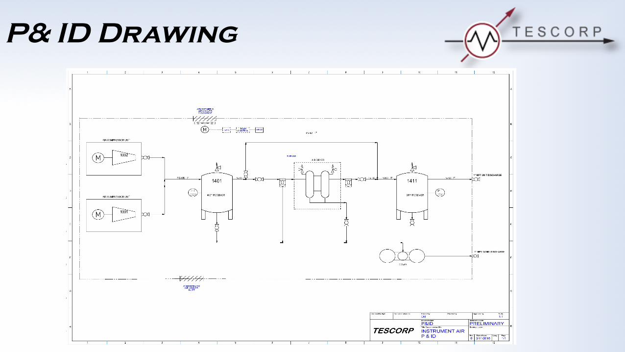
P& ID Drawing

Compressor Solution
• How much pressure is required?• How much air flow is required?• What is the air quality required?• What is the operating duty cycle?
There is no one compressor type that “Is the Best”. Each type of compression has an application where it is the better choice for the service based on the customers requirements.
• What is the first cost?• What is the total cost of ownership?• What special requirements does this application demand?
Equipment Selection Criteria Questions:
TESCORP utilizes many types of compressors. TESCORP selects the compressor by their merits to best meet a specific compression requirement or site environment.
Design Criteria Questions:

Compressor Solution
AIR COMPRESSOR SELECTION
PressureRange** CapacityRange** AirQuality DutyCycle Initialcost 5YearCost
Reciprocating*Lubricated
0-500 psig0-35bar
0-125 cfm0-60l/sec
Low 50-75% Low MedHigh
Reciprocating*Oil-less
0-150 psig0-10bar
0-100 cfm0-48l/sec
High 50-75% Med High
RotaryScrewLubricated
0-230 psig0-16bar
5-3000 cfm0-85m3/min
Low 100% Med MedLow
RotaryScrewOil-free
0-150 psig0-10bar
50-3000 cfm1-85m3/min
High 100% High Med
Centrifugal0-350 psig0-24bar
250-20000 cfm7-560m3/min
High 100% High Low
PrintedfromQUINCYCOMPRESSOR
There are many factors in determining the best compressor type for each application. The first is the flow requirement in pressure and volume. Many types of compressors are available for varying applications. A quick reference can be
made for the initial selection per the following:

Dryer Solutions
Air Purge Regeneration - a common regenerative dryer system where the wet tower is dried by diverting a small flow of the dry air from the active drying tower back through the saturated tower. This dry air adsorbs the moisture and expels it to the atmosphere.
The two (2) most common regenerative process are:
Heater Regeneration - another common regenerative dryer system where the wet tower is dried by a heater element that is incorporated in the towers. When in the regeneration mode, the heater element heats the tower to the point of boiling the entrained water to a vapor that is expelled from the wet tower into the atmosphere.

Dryer Solutions
Air Purge Regeneration:• Air purge system is the simplest system to implement. • The air flow requirement for regeneration is usually 15-20 percent of the total air flow.
Heater Regeneration: • Does not utilize any of the compressor capacity.• Requires excess electrical power for regeneration.
Both dryer types accomplish the required dew point reduction and add some inefficiencies to the Instrument Air Unit by either utilizing some of the systems horsepower or adding extra electrical power requirements to the system. The consideration for this regeneration cost must be applied to the initial sizing of the compressor unit.

Dryer Solutions
The image above illustrates that the moisture laden air is flowing through and being dried in tower No. 1, while tower No. 2 is being regenerated for use once the first tower is saturated.
The image above indicates a reversal of process where tower No. 2 is drying the airflow and tower No. 1 is in the regeneration mode
Air Storage
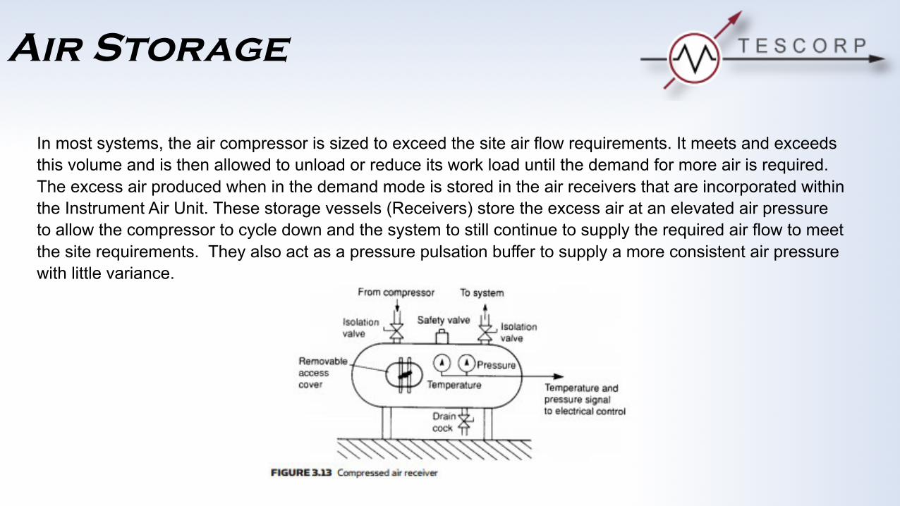
In most systems, the air compressor is sized to exceed the site air flow requirements. It meets and exceeds this volume and is then allowed to unload or reduce its work load until the demand for more air is required. The excess air produced when in the demand mode is stored in the air receivers that are incorporated within the Instrument Air Unit. These storage vessels (Receivers) store the excess air at an elevated air pressure to allow the compressor to cycle down and the system to still continue to supply the required air flow to meet the site requirements. They also act as a pressure pulsation buffer to supply a more consistent air pressure with little variance.

Air Storage
The storage volume of the receiver is based upon the vessel volume and the excessive amount of pressure that it is stored at above the required site pressure requirements. This volume is calculated as “flow time” available from the storage at the site required flow:
T=(v(P1 – P2))/C)Pa
Or, if a extra volume capacity is required for additional flow time, then the storage volume is calculated by:
V=(T*C*Pa)/(P1–P2)
T=timeinminutesofflow V=volumeoftheairreceiverinFt3
P1 =upperpressurelimits(Psia) P2 =lowerpressurelimits(Psia)
C=airconsumptiontosite(Scfm) Pa =atmosphericpressure(Psia)
The Instrument Air Unit storage volume may vary to meet the design requirements by adding more storage volume or operating at a higher storage pressure. These are variables within the system that are made in the initial design phase. But, at any time, “Dry Air” storage may be added to the site air system as an ancillary component.

Air Storage
TESCORP Standard’s incorporates (2) air storage vessels on all Instrument Air Units.
Wet Air Storage - This is the first step in the drying process to meet a required site pressure dew point. The air stream being generated by the compressor at the desired discharge pressure will be water saturated.
• A significant amount of the entrained water vapor in the air stream will be simply eliminated in the wet air receiver by allowing a period of time for retention.
• This produced water is then eliminated by a condensate trap & drain from the air flow.
• By reducing the amount of entrained water in the air stream to the air dryer assembly we increase its efficiency and lessens the work load.
• The storage of the air in the wet air receiver also acts to stabilize the pressure surges and create a more steady flow into the air dryer assembly.

Air Storage
TESCORP Standard’s incorporates (2) air storage vessels on all Instrument Air Units.
Dry Air Storage- This is conditioned air that is at the required dew point for safe storage and use in the site environment. Additional storage of this conditioned air maybe added at any time.
• Reduces cycling of the compressor.
• Allows the site latitude to meet demands that may exceed the compressor unit’s capacity.
Note: There is a codicil to the added storage volume in that consideration must be given to the “compressor loading”. This may require the compressor to stay 100% continuously loaded for extended periods of time costing excess power costs or excessive operating temperatures.
Air Storage
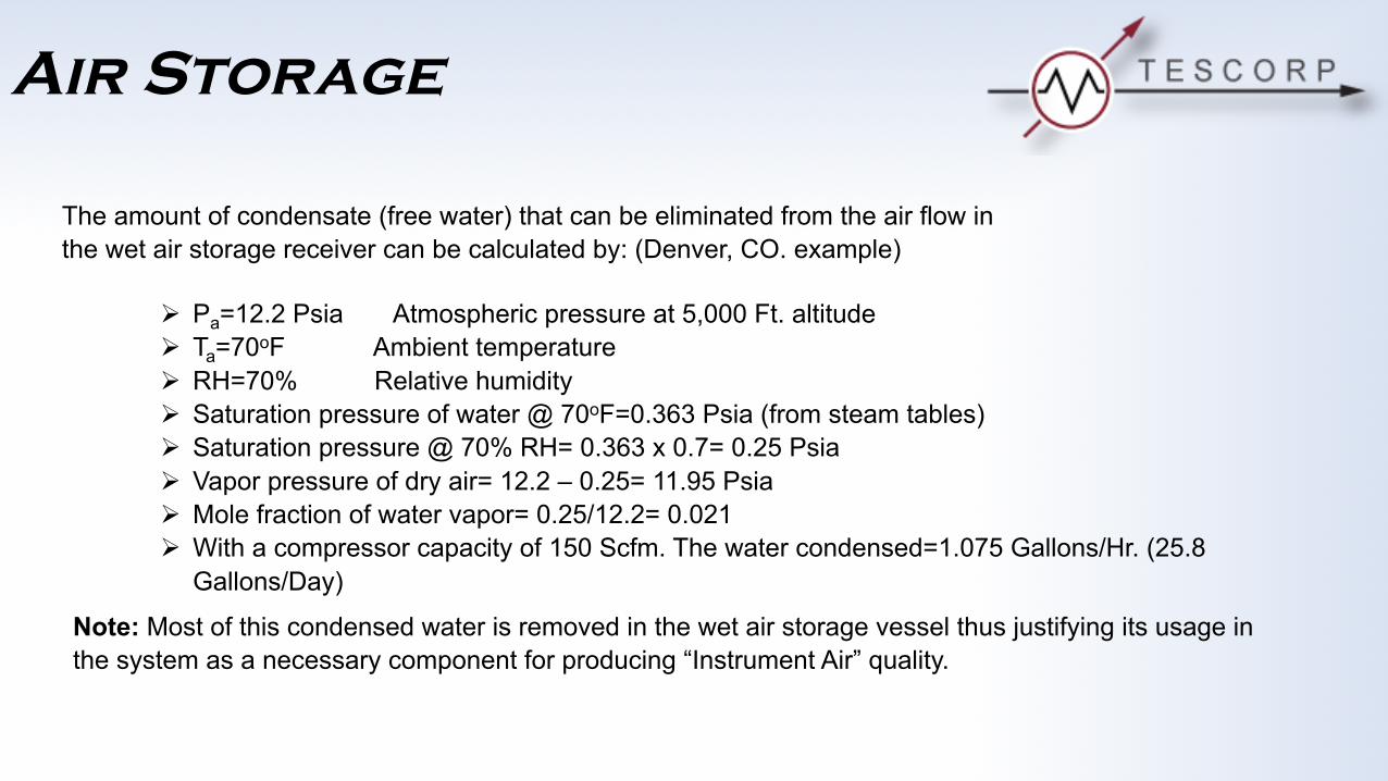
The amount of condensate (free water) that can be eliminated from the air flow in the wet air storage receiver can be calculated by: (Denver, CO. example)
Ø Pa=12.2 Psia Atmospheric pressure at 5,000 Ft. altitudeØ Ta=70oF Ambient temperatureØ RH=70% Relative humidityØ Saturation pressure of water @ 70oF=0.363 Psia (from steam tables)Ø Saturation pressure @ 70% RH= 0.363 x 0.7= 0.25 PsiaØ Vapor pressure of dry air= 12.2 – 0.25= 11.95 PsiaØ Mole fraction of water vapor= 0.25/12.2= 0.021Ø With a compressor capacity of 150 Scfm. The water condensed=1.075 Gallons/Hr. (25.8
Gallons/Day)
Note: Most of this condensed water is removed in the wet air storage vessel thus justifying its usage in the system as a necessary component for producing “Instrument Air” quality.

Condensate Management
Oil/Water Separator- Condensed water from the wet air storage and the pre-filter into the dryer is a combination of mostly produced water with traces of oil that is a carry-over from the compressor oil separator. Although minute in the percentage of concentration, the presence of this condensate prohibits it from free discharge into the environment. Therefore, this produced water must be conditioned prior to discharge through the use of an Oil/Water separator that removes the oil from the effluent.
The "OSD" Oil/Water Separator removes the oil from the produced water allowing it to be freely discharged into the environment.