TES-AN-25M INCLINOMETER SYSTEM - Tritech TES... · TES-AN-25M INCLINOMETER SYSTEM ... inserted into...
25
USER’S MANUAL TES-AN-25M INCLINOMETER SYSTEM Doc. # WI 6002.81 Rev.00 Printed March 07
Transcript of TES-AN-25M INCLINOMETER SYSTEM - Tritech TES... · TES-AN-25M INCLINOMETER SYSTEM ... inserted into...

USER’S MANUAL
TES- AN- 2 5 M
I NCL I NO M ETER SYSTEM
Doc. # WI 6002.81 Rev.00
Printed March 07
Inclinometer System Users’ manual
Page 1-1
1. Introduction
The TES-AN-25 inclinometer system is used for reliable measurement of lateral movement in applications like:
� Earth movement in landslide zone. � Detecting shear planes in hydraulic structures. � Measuring stability during construction. � Deflection of diaphragm/retaining walls and piles under load.
The inclinometer system provides significant quantitative data on magnitude of inclination and its variation with time. It gives information on pattern of deformation and effectiveness of construction control measures. It helps in monitoring behaviour after construction and indicates potentially dangerous conditions that may adversely affect stability of the structure, its foundation and surrounding area. It also provides basic data for design improvement that will promote safer and economical design and construction.
The TES-AN-25 inclinometer system is an accurate instrumentation system. Its datalogger has built-in data storage facilities and capability of transferring stored data to a computer. The inclinometer probe operates in a plastic grooved casing which may be “built-up” with embankment fill, inserted into boreholes or attached externally to structures or hillsides. The inclinometer casing may be installed with telescopic couplings as construction progresses providing opportunity for settlement measurements, or it may be installed with butt joints in drill holes in abutments or completed embankments if no significant settlement is anticipated.
1.1. Displacement measurement
For measurement of vertical displacement, magnetic targets may be fixed to access casing at selected points. Measuring settlement by using inclinometer casing has largely replaced the earlier method using separate settlement devices like the cross arm. The same installation is now used to measure settlement as well as lateral movement. For details refer to data sheet 1098 “Magnetic Extensometer System”.
1.2. Casing storage
� Do not apply too much load or force on casing. � Store all items in a proper place in a ventilated building under shade of a roof � Do not warp or bend during storage. � Avoid direct sunlight on plastic casing and accessories as it can cause deformation of casing.
1.3. Conventions used in this manual
WARNING! Warning messages calls attention to a procedure or practice, that if not properly followed could possibly cause personal injury.
CAUTION: Caution messages calls attention to a procedure or practice, that if not properly followed may result in loss of data or damage to equipment.
NOTE: Note contains important information and is set off from regular text to draw the users’ attention.
1.4. General information
This users’ manual is intended to provide you with sufficient information for installing and making optimum use of ABS inclinometer casing. The manual also contains instructions on how to set-up for lowering inclinometer probe into gage well for purpose of taking inclination readings.
NOTE: Installation personnel must have a background of good installation practices and knowledge of
Users’ Manual Inclinometer System
Page 1-2
the fundamentals of geotechnics. Novices may find it very difficult to carry on the installation work. The intricacies involved in installation are such that even if a single essential but apparently minor requirement is ignored or overlooked, the most reliable of instruments will be rendered useless.
A lot of effort has been made in preparing this instruction manual. However the best of instruction manuals cannot provide for each and every condition in the field, which may affect performance of the sensor. Also, blindly following the instruction manual will not guarantee success. Sometimes, depending upon field conditions, installation personnel will have to consciously depart from the written text and use their knowledge and common sense to find the solution to a particular problem.
This equipment should be installed, maintained and operated by qualified personnel. Any errors or omissions in installation, data or data interpretation are not the responsibility of TRITECH Instruments Pte. Ltd.
For details on how to operate the inclinometer data logger, please refer to operating manual # WI 6002.80.
To make this manual more useful we invite your valuable comments and suggestions regarding any additions or enhancements. We request you to please let us know of any errors that are found while going through the manual.
1.5. How to use this manual
The manual is divided into a number of sections. Each section contains a specific type of information. The list given below tells you where to look for in this manual if you need some specific information.
For principle of operation: See § 2.1 ‘Operating principle’. For inclinometer system manufactured by TRITECH: See § 2.2 ‘General description’. For specifications of the probe and data logger: See § 3 ‘system specifications’. For essential tools and accessories: See § 4 ‘Tools and accessories required for installation’. For installation of PVC casing: See § 5 ‘Installation of casing’. For taking readings: See § 6 ‘Preparation for and obtaining readings’.
Inclinometer System Users’ manual
Page 2-1
2. Inclinometer system
2.1. Operating principle
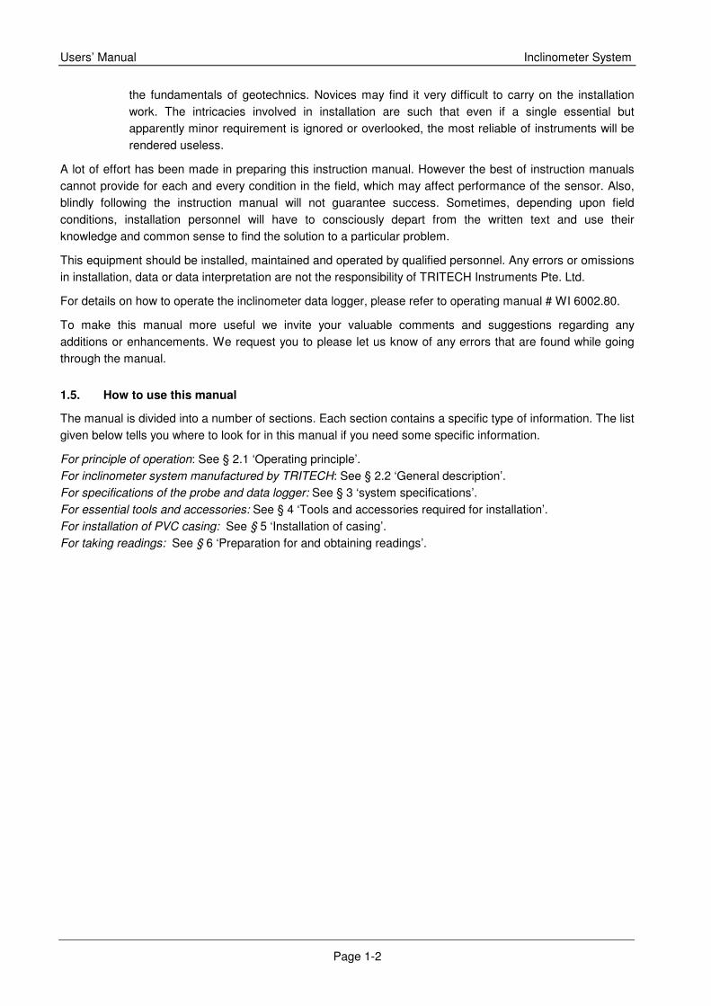
The first step is to make a near vertical gage well by installing casing in a borehole, embedding in an earth/rock fill or concrete structure during construction or fixing to face of a completed structure. The inclinometer probe is then passed through entire length of gage well, taking readings at fixed pre-determined depths from bottom to top. A dual accelerometer probe senses inclination of casing in two planes at right angles to each other. Voltage output from probe is directly proportional to sine of angle of inclination of long axis of probe from the vertical. A positive output voltage indicates a negative angle of inclination.
A set of initial base reading is taken at given depths within the gage well. This forms the reference datum. Subsequent reading sets are compared with this reference datum. All subsequent readings are taken over a period of time at identical depths, thereby indicating rate, magnitude, and direction of lateral deformation. The inclination is displayed in terms of angular or horizontal displacement (deviation) on the electronic readout equipment at ground level with the operator.
Provided that one end of access casing is known to be fixed, it is possible to obtain a complete profile of the gage well by taking a succession of readings. By comparing these profiles, the horizontal displacement of gage well at different depths over a period of time is determined.
2.2. General description
The TES-AN-25 inclinometer system basically consists of:
� Access casing and fittings � Tilt sensing probe � Interconnecting cable with reel and cable holder � Data logger
2.2.1. TES-AN-25/1 access casing and fittings
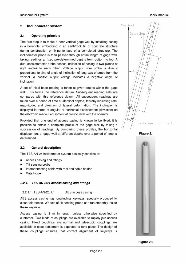
2.2.1.1. TES-AN-25/1.1 ABS access casing
ABS access casing has longitudinal keyways, specially produced to close tolerances. Wheels of tilt sensing probe can run smoothly inside these keyways.
Access casing is 3 m in length unless otherwise specified by customer. Two kinds of couplings are available to rapidly join access casing. Fixed couplings are normal and telescopic couplings are available in case settlement is expected to take place. The design of these couplings ensures that correct alignment of keyways is
Figure 2.1
Figure 2.2
Users’ Manual Inclinometer System
Page 2-2
maintained throughout the depth of gage well.
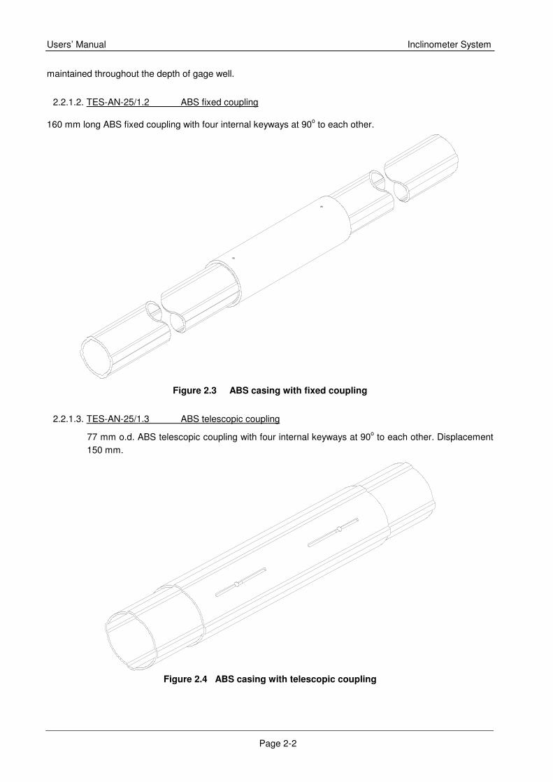
2.2.1.2. TES-AN-25/1.2 ABS fixed coupling
160 mm long ABS fixed coupling with four internal keyways at 90o to each other.
Figure 2.3 ABS casing with fixed coupling
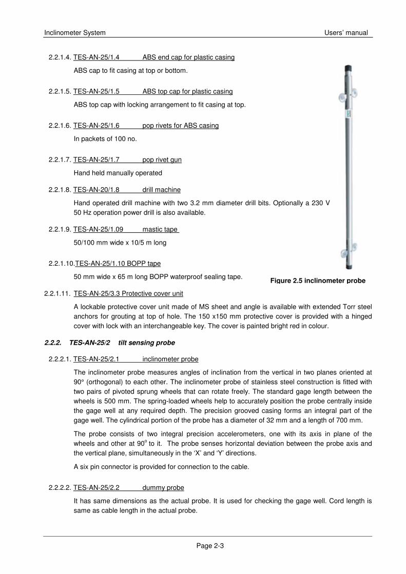
2.2.1.3. TES-AN-25/1.3 ABS telescopic coupling
77 mm o.d. ABS telescopic coupling with four internal keyways at 90o to each other. Displacement 150 mm.
Figure 2.4 ABS casing with telescopic coupling
Inclinometer System Users’ manual
Page 2-3
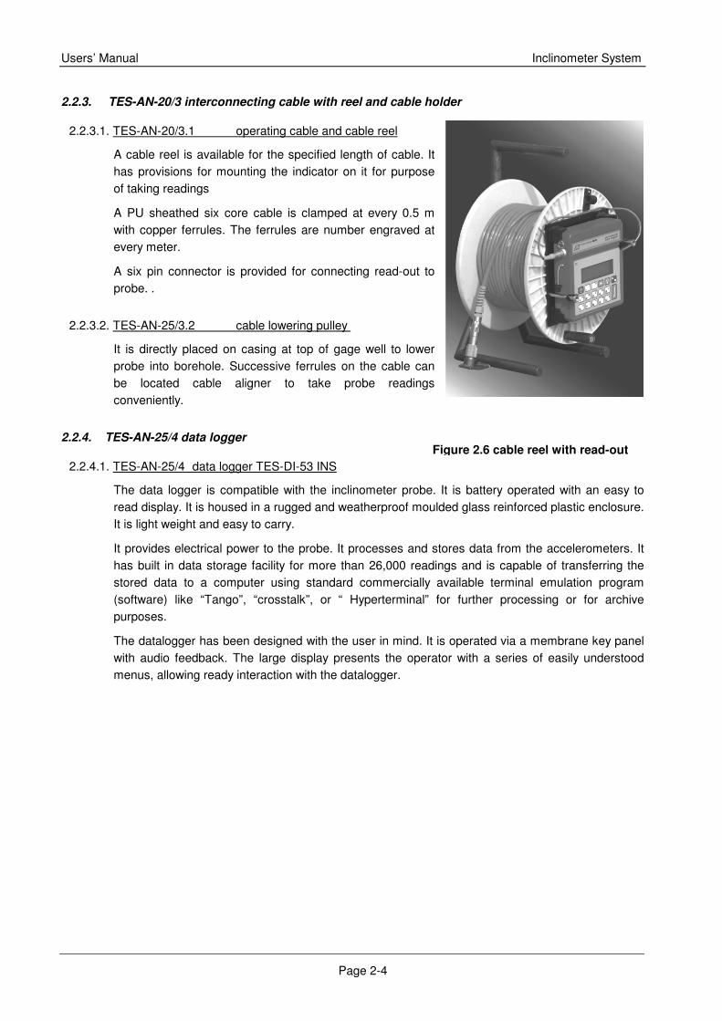
Figure 2.5 inclinometer probe
2.2.1.4. TES-AN-25/1.4 ABS end cap for plastic casing
ABS cap to fit casing at top or bottom.
2.2.1.5. TES-AN-25/1.5 ABS top cap for plastic casing
ABS top cap with locking arrangement to fit casing at top.
2.2.1.6. TES-AN-25/1.6 pop rivets for ABS casing
In packets of 100 no.
2.2.1.7. TES-AN-25/1.7 pop rivet gun
Hand held manually operated
2.2.1.8. TES-AN-20/1.8 drill machine
Hand operated drill machine with two 3.2 mm diameter drill bits. Optionally a 230 V 50 Hz operation power drill is also available.
2.2.1.9. TES-AN-25/1.09 mastic tape
50/100 mm wide x 10/5 m long
2.2.1.10.TES-AN-25/1.10 BOPP tape
50 mm wide x 65 m long BOPP waterproof sealing tape.
2.2.1.11. TES-AN-25/3.3 Protective cover unit
A lockable protective cover unit made of MS sheet and angle is available with extended Torr steel anchors for grouting at top of hole. The 150 x150 mm protective cover is provided with a hinged cover with lock with an interchangeable key. The cover is painted bright red in colour.
2.2.2. TES-AN-25/2 tilt sensing probe
2.2.2.1. TES-AN-25/2.1 inclinometer probe
The inclinometer probe measures angles of inclination from the vertical in two planes oriented at 90° (orthogonal) to each other. The inclinometer probe of stainless steel construction is fitted with two pairs of pivoted sprung wheels that can rotate freely. The standard gage length between the wheels is 500 mm. The spring-loaded wheels help to accurately position the probe centrally inside the gage well at any required depth. The precision grooved casing forms an integral part of the gage well. The cylindrical portion of the probe has a diameter of 32 mm and a length of 700 mm.
The probe consists of two integral precision accelerometers, one with its axis in plane of the wheels and other at 90o to it. The probe senses horizontal deviation between the probe axis and the vertical plane, simultaneously in the ‘X’ and ‘Y’ directions.
A six pin connector is provided for connection to the cable.
2.2.2.2. TES-AN-25/2.2 dummy probe
It has same dimensions as the actual probe. It is used for checking the gage well. Cord length is same as cable length in the actual probe.
Users’ Manual Inclinometer System
Page 2-4
2.2.3. TES-AN-20/3 interconnecting cable with reel and cable holder
2.2.3.1. TES-AN-20/3.1 operating cable and cable reel
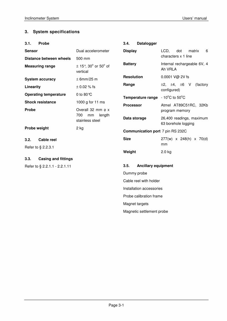
A cable reel is available for the specified length of cable. It has provisions for mounting the indicator on it for purpose of taking readings
A PU sheathed six core cable is clamped at every 0.5 m with copper ferrules. The ferrules are number engraved at every meter.
A six pin connector is provided for connecting read-out to probe. .
2.2.3.2. TES-AN-25/3.2 cable lowering pulley
It is directly placed on casing at top of gage well to lower probe into borehole. Successive ferrules on the cable can be located cable aligner to take probe readings conveniently.
2.2.4. TES-AN-25/4 data logger
2.2.4.1. TES-AN-25/4 data logger TES-DI-53 INS
The data logger is compatible with the inclinometer probe. It is battery operated with an easy to read display. It is housed in a rugged and weatherproof moulded glass reinforced plastic enclosure. It is light weight and easy to carry.
It provides electrical power to the probe. It processes and stores data from the accelerometers. It has built in data storage facility for more than 26,000 readings and is capable of transferring the stored data to a computer using standard commercially available terminal emulation program (software) like “Tango”, “crosstalk”, or “ Hyperterminal” for further processing or for archive purposes.
The datalogger has been designed with the user in mind. It is operated via a membrane key panel with audio feedback. The large display presents the operator with a series of easily understood menus, allowing ready interaction with the datalogger.
Figure 2.6 cable reel with read-out
Inclinometer System Users’ manual
Page 3-1
3. System specifications
3.1. Probe
Sensor Dual accelerometer
Distance between wheels 500 mm
Measuring range ± 15°, 30o or 50o of vertical
System accuracy ± 6mm/25 m
Linearity ± 0.02 % fs
Operating temperature 0 to 80°C
Shock resistance 1000 g for 11 ms
Probe Overall 32 mm φ x 700 mm length stainless steel
Probe weight 2 kg
3.2. Cable reel
Refer to § 2.2.3.1
3.3. Casing and fittings
Refer to § 2.2.1.1 - 2.2.1.11
3.4. Datalogger
Display LCD, dot matrix 6 characters x 1 line
Battery Internal rechargeable 6V, 4 Ah VRLA
Resolution 0.0001 V@ 2V fs
Range ±2, ±4, ±6 V (factory configured)
Temperature range - 10oC to 50oC
Processor Atmel AT89C51RC, 32Kb program memory
Data storage 26,400 readings, maximum 63 borehole logging
Communication port 7 pin RS 232C
Size 277(w) x 248(h) x 70(d) mm
Weight 2.0 kg
3.5. Ancillary equipment
Dummy probe
Cable reel with holder
Installation accessories
Probe calibration frame
Magnet targets
Magnetic settlement probe
Inclinometer System Users’ manual
Page 4-1
4. Tools & accessories required for installation
It should be ensured that following tools and accessories required for proper installation of the inclinometer PVC casing and for taking readings are available:
4.1 Tool box
4.2 50 mm wide water proof sealing tape
4.3 Spanner 16/18
4.4 Screw driver 100 mm
4.5 Voltage tester
4.6 Pliers 150 mm
4.7 Flat file 150 mm
4.8 Safety line or tension cable in case hole is very deep
4.9 Clean water supply to clean casing
4.10 Hand saw with three 30 cm blades
4.11 Casing collar protection if required
4.12 Grout tube - requisite length
4.13 Acetone
4.14 Aluminium pop rivets - four per joint plus some extra
4.15 Pop rivet gun
4.16 Drill with a 3.15 mm spare drill bit.
4.17 Casing clamps - 2 sets
4.18 Plumb bob with 5 m chord
4.19 Casing cap with guy ropes (for embankment installations)
4.20 Casing ‘U’ clamps and grout bolts (For installation on concrete structures)
Inclinometer System Users’ manual
Page 5-1
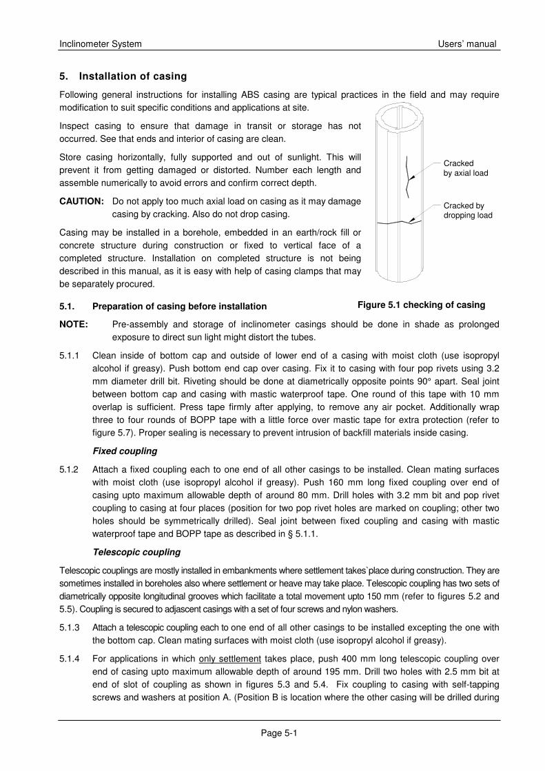
Figure 5.1 checking of casing
5. Installation of casing
Following general instructions for installing ABS casing are typical practices in the field and may require modification to suit specific conditions and applications at site.
Inspect casing to ensure that damage in transit or storage has not occurred. See that ends and interior of casing are clean.
Store casing horizontally, fully supported and out of sunlight. This will prevent it from getting damaged or distorted. Number each length and assemble numerically to avoid errors and confirm correct depth.
CAUTION: Do not apply too much axial load on casing as it may damage casing by cracking. Also do not drop casing.
Casing may be installed in a borehole, embedded in an earth/rock fill or concrete structure during construction or fixed to vertical face of a completed structure. Installation on completed structure is not being described in this manual, as it is easy with help of casing clamps that may be separately procured.
5.1. Preparation of casing before installation
NOTE: Pre-assembly and storage of inclinometer casings should be done in shade as prolonged exposure to direct sun light might distort the tubes.
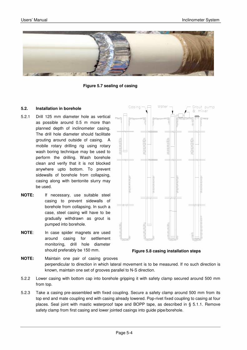
5.1.1 Clean inside of bottom cap and outside of lower end of a casing with moist cloth (use isopropyl alcohol if greasy). Push bottom end cap over casing. Fix it to casing with four pop rivets using 3.2 mm diameter drill bit. Riveting should be done at diametrically opposite points 90° apart. Seal joint between bottom cap and casing with mastic waterproof tape. One round of this tape with 10 mm overlap is sufficient. Press tape firmly after applying, to remove any air pocket. Additionally wrap three to four rounds of BOPP tape with a little force over mastic tape for extra protection (refer to figure 5.7). Proper sealing is necessary to prevent intrusion of backfill materials inside casing.
Fixed coupling
5.1.2 Attach a fixed coupling each to one end of all other casings to be installed. Clean mating surfaces with moist cloth (use isopropyl alcohol if greasy). Push 160 mm long fixed coupling over end of casing upto maximum allowable depth of around 80 mm. Drill holes with 3.2 mm bit and pop rivet coupling to casing at four places (position for two pop rivet holes are marked on coupling; other two holes should be symmetrically drilled). Seal joint between fixed coupling and casing with mastic waterproof tape and BOPP tape as described in § 5.1.1.
Telescopic coupling
Telescopic couplings are mostly installed in embankments where settlement takes`place during construction. They are sometimes installed in boreholes also where settlement or heave may take place. Telescopic coupling has two sets of diametrically opposite longitudinal grooves which facilitate a total movement upto 150 mm (refer to figures 5.2 and 5.5). Coupling is secured to adjascent casings with a set of four screws and nylon washers.
5.1.3 Attach a telescopic coupling each to one end of all other casings to be installed excepting the one with the bottom cap. Clean mating surfaces with moist cloth (use isopropyl alcohol if greasy).
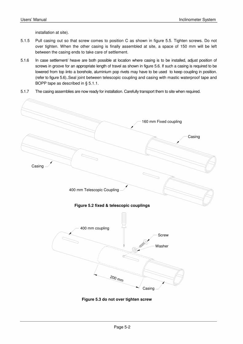
5.1.4 For applications in which only settlement takes place, push 400 mm long telescopic coupling over end of casing upto maximum allowable depth of around 195 mm. Drill two holes with 2.5 mm bit at end of slot of coupling as shown in figures 5.3 and 5.4. Fix coupling to casing with self-tapping screws and washers at position A. (Position B is location where the other casing will be drilled during
Crackedby axial load
Cracked bydropping load
Users’ Manual Inclinometer System
Page 5-2
installation at site).
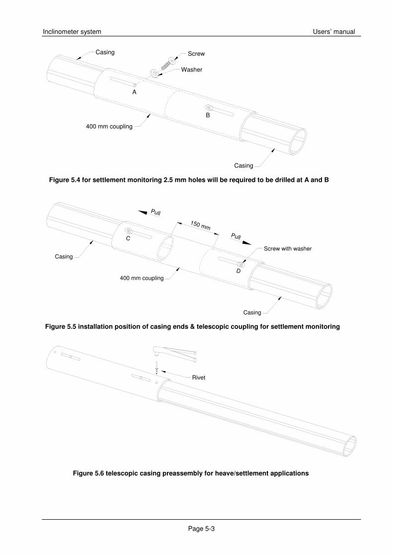
5.1.5 Pull casing out so that screw comes to position C as shown in figure 5.5. Tighten screws. Do not over tighten. When the other casing is finally assembled at site, a space of 150 mm will be left between the casing ends to take care of settlement.
5.1.6 In case settlement/ heave are both possible at location where casing is to be installed, adjust position of screws in groove for an appropriate length of travel as shown in figure 5.6. If such a casing is required to be lowered from top iinto a borehole, aluminium pop rivets may have to be used to keep coupling in position. (refer to figure 5.6)..Seal joint between telescopic coupling and casing with mastic waterproof tape and BOPP tape as described in § 5.1.1.
5.1.7 The casing assemblies are now ready for installation. Carefully transport them to site when required.
160 mm Fixed coupling
Casing
400 mm Telescopic Coupling
Casing
Figure 5.2 fixed & telescopic couplings
400 mm coupling
Casing
Screw
200 mm
Washer
Figure 5.3 do not over tighten screw
Inclinometer system Users’ manual
Page 5-3
Casing
400 mm coupling
Screw
Washer
Casing
A
B
Casing
Casing
150 mm
400 mm coupling
Pull
Screw with washer
Pull
C
D
Rivet
Figure 5.4 for settlement monitoring 2.5 mm holes will be required to be drilled at A and B
are
Figure 5.6 telescopic casing preassembly for heave/settlement applications
Figure 5.5 installation position of casing ends & telescopic coupling for settlement monitoring
Users’ Manual Inclinometer System
Page 5-4
Figure 5.8 casing installation steps
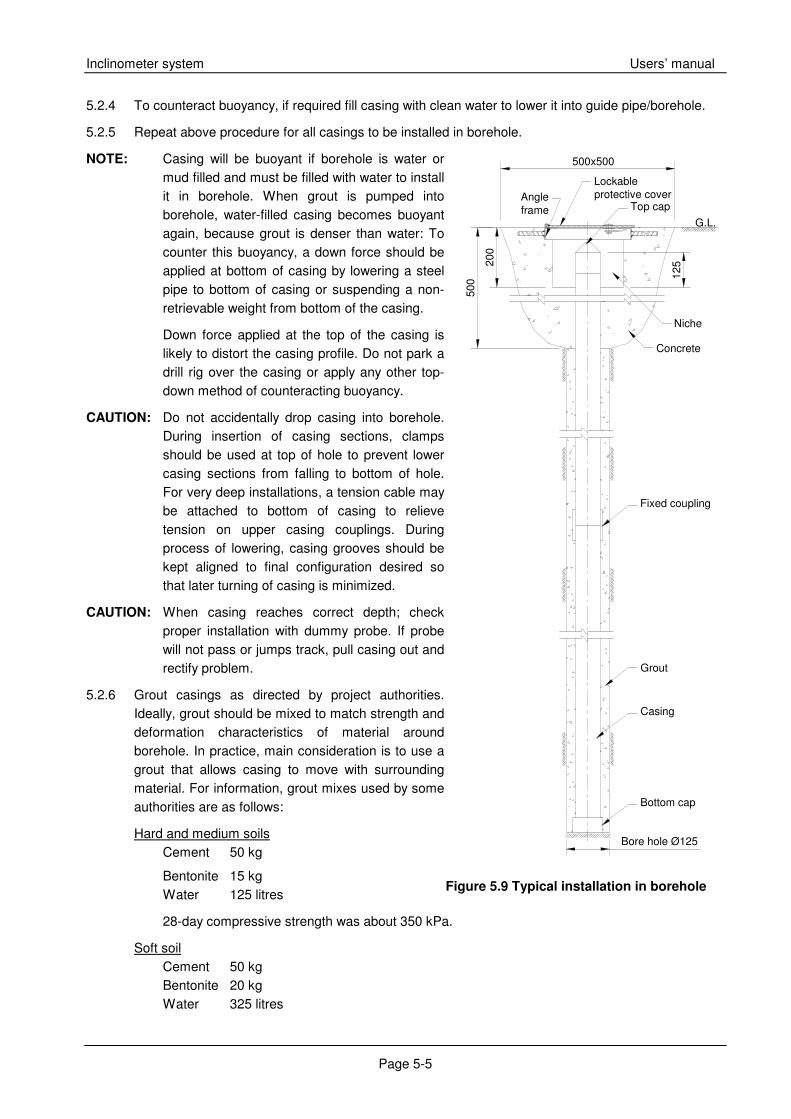
5.2. Installation in borehole
5.2.1 Drill 125 mm diameter hole as vertical as possible around 0.5 m more than planned depth of inclinometer casing. The drill hole diameter should facilitate grouting around outside of casing. A mobile rotary drilling rig using rotary wash boring technique may be used to perform the drilling. Wash borehole clean and verify that it is not blocked anywhere upto bottom. To prevent sidewalls of borehole from collapsing, casing along with bentonite slurry may be used.
NOTE: If necessary, use suitable steel casing to prevent sidewalls of borehole from collapsing. In such a case, steel casing will have to be gradually withdrawn as grout is pumped into borehole.
NOTE: In case spider magnets are used around casing for settlement monitoring, drill hole diameter should preferably be 150 mm.
NOTE: Maintain one pair of casing grooves perpendicular to direction in which lateral movement is to be measured. If no such direction is known, maintain one set of grooves parallel to N-S direction.
5.2.2 Lower casing with bottom cap into borehole gripping it with safety clamp secured around 500 mm from top.
5.2.3 Take a casing pre-assembled with fixed coupling. Secure a safety clamp around 500 mm from its top end and mate coupling end with casing already lowered. Pop-rivet fixed coupling to casing at four places. Seal joint with mastic waterproof tape and BOPP tape, as described in § 5.1.1. Remove safety clamp from first casing and lower jointed casings into guide pipe/borehole.
Figure 5.7 sealing of casing
Inclinometer system Users’ manual
Page 5-5
Fig. 5.9 casing installation in borehole
Figure 5.9 Typical installation in borehole
5.2.4 To counteract buoyancy, if required fill casing with clean water to lower it into guide pipe/borehole.
5.2.5 Repeat above procedure for all casings to be installed in borehole.
NOTE: Casing will be buoyant if borehole is water or mud filled and must be filled with water to install it in borehole. When grout is pumped into borehole, water-filled casing becomes buoyant again, because grout is denser than water: To counter this buoyancy, a down force should be applied at bottom of casing by lowering a steel pipe to bottom of casing or suspending a non-retrievable weight from bottom of the casing.
Down force applied at the top of the casing is likely to distort the casing profile. Do not park a drill rig over the casing or apply any other top-down method of counteracting buoyancy.
CAUTION: Do not accidentally drop casing into borehole. During insertion of casing sections, clamps should be used at top of hole to prevent lower casing sections from falling to bottom of hole. For very deep installations, a tension cable may be attached to bottom of casing to relieve tension on upper casing couplings. During process of lowering, casing grooves should be kept aligned to final configuration desired so that later turning of casing is minimized.
CAUTION: When casing reaches correct depth; check proper installation with dummy probe. If probe will not pass or jumps track, pull casing out and rectify problem.
5.2.6 Grout casings as directed by project authorities. Ideally, grout should be mixed to match strength and deformation characteristics of material around borehole. In practice, main consideration is to use a grout that allows casing to move with surrounding material. For information, grout mixes used by some authorities are as follows:
Hard and medium soils Cement 50 kg
Bentonite 15 kg Water 125 litres
28-day compressive strength was about 350 kPa.
Soft soil Cement 50 kg Bentonite 20 kg Water 325 litres
500
200
125
500x500
Concrete
Fixed coupling
Bottom cap
Casing
Top cap
Bore hole Ø125
Grout
Niche
G.L.
Lockableprotective coverAngle
frame
Users’ Manual Inclinometer System
Page 5-6
28-day compressive strength was about 30 kPa.
Please verify above values yourself in actual conditions before use. TRITECH takes no responsibility for correctness of above information at your site as the compressive strength values are dependent upon geology of site and environmental conditions.
Pull out and dismantle grout pipes one by one as the hole is being filled with grout.
NOTE: Preferably use 20 mm nominal diameter rigid PVC pipe lengths jointed using threaded sockets for grouting. Lower above tubes say up to 0.5 m above bottom of borehole.
NOTE: Use a mixer, a grout pump, a pipe or hose for delivering grout. Do not mix grout by hand. Also do not use a water pump to place grout, since pumping grout would damage it.
Properly mixed grout should be free of lumps. It has to be thin enough to pump but thick enough to set in a reasonable length of time. If mixture is too watery, it will shrink excessively, leaving upper portion of the borehole ungrouted. Avoid use of admixtures and grouts that cure at high temperature since these may damage the casing.
Mix cement with water first. Then mix in bentonite. Adjust amount of bentonite to produce a grout within consistency of heavy cream. If grout is too thin, the solids and water will separate. If the grout is too thick, it will be difficult to pump.
The use of hydrated lime rather than cement is sometimes recommended to provide for a more responsive, somewhat weaker backfill.
For plastic casing, heat of hydration of grout or excess grout pressure can deform the plastic. This problem can be eliminated by maintaining casing full of water until grout has set or by grouting hole in stages.
CAUTION: Experience shows that sand or pea gravel should not be used as backfill material unless it is absolutely necessary. These backfill tend to mask movement, not allowing a rigid shear plane to reach the casing.
NOTE: Pre-grouting is sometimes done in case of a shallow borehole. It is also useful when there is not enough space for the grout pipe in the annulus between the casing and the borehole wall.
5.2.7 Flush inside of casing with clean water after grouting to prevent any leaked in grout from sticking to inside of casing and impairing movement of probe.
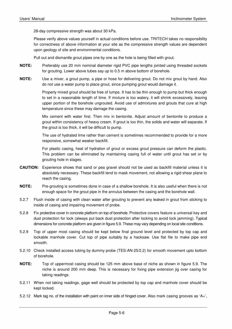
5.2.8 Fix protective cover in concrete platform on top of borehole. Protective covers feature a universal key and dust protection for lock (always put back dust protection after locking to avoid lock jamming). Typical dimensions for concrete platform are given in figure 5.9. These may vary depending on local site conditions.
5.2.9 Top of upper most casing should be kept below final ground level and protected by top cap and lockable manhole cover. Cut top of pipe suitably by a hacksaw. Use flat file to make pipe end smooth.
5.2.10 Check installed access tubing by dummy probe (TES-AN-25/2.2) for smooth movement upto bottom of borehole.
NOTE: Top of uppermost casing should be 125 mm above base of niche as shown in figure 5.9. The niche is around 200 mm deep. This is necessary for fixing pipe extension jig over casing for taking readings.
5.2.11 When not taking readings, gage well should be protected by top cap and manhole cover should be kept locked.
5.2.12 Mark tag no. of the installation with paint on inner side of hinged cover. Also mark casing grooves as ‘A+’,
Inclinometer system Users’ manual
Page 5-7
Figure 5.10 installation in diaphragm wall
’B+’ ,’A-’ and ‘B-’ with permanent ink marker pen. If uppermost probe wheel is pointed in direction of major principle plane of movement, casing groove pointing in this direction is marked as ‘A+’. Looking down the well, directions ‘B+’, ’A-’ and ‘B-’ are clockwise from ‘A+’.
NOTE: Plying of heavy machinery such as cranes, loaded trucks etc. near protective cover should not be allowed and if required proper fencing with warning flags should be provided. In case it is not possible to avoid movement of heavy machinery over protective cover, specially procure heavy duty covers from factory and embed in a heavy concrete platform.
NOTE: If telescopic coupling is used, settlement sections must be inserted appropriately extended or collapsed. Grease telescopic joint and use mastic and BOPP tape to keep telescopic section at required opening and also to prevent intrusion of grout or backfill materials inside casing.
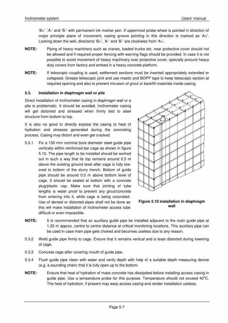
5.3. Installation in diaphragm wall or pile
Direct installation of inclinometer casing in diaphragm wall or a pile is problematic. It should be avoided. Inclinometer casing will get distorted and stressed when firmly tied to steel structure from bottom to top.
It is also no good to directly expose the casing to heat of hydration and stresses generated during the concreting process. Casing may distort and even get cracked.
5.3.1 Fix a 150 mm nominal bore diameter steel guide pipe vertically within reinforced bar cage as shown in figure 5.10. The pipe length to be installed should be worked out in such a way that its top remains around 0.5 m above the existing ground level after cage is fully low-ered to bottom of the slurry trench. Bottom of guide pipe should be around 0.5 m above bottom level of cage. It should be sealed at bottom with a concrete plug/plastic cap. Make sure that jointing of tube lengths is water proof to prevent any grout/concrete from entering into it, while cage is being concreted. Use of dented or distorted pipes shall not be done as this will make installation of inclinometer access tube difficult or even impossible.
NOTE: It is recommended that an auxiliary guide pipe be installed adjacent to the main guide pipe at 1.25 m approx. centre to centre distance at critical monitoring locations. This auxiliary pipe can be used in case main pipe gets choked and becomes useless due to any reason.
5.3.2 Weld guide pipe firmly to cage. Ensure that it remains vertical and is least distorted during lowering of cage.
5.3.3 Concrete cage after covering mouth of guide pipe.
5.3.4 Flush guide pipe clean with water and verify depth with help of a suitable depth measuring device (e.g. a sounding chain) that it is fully open up to the bottom.
NOTE: Ensure that heat of hydration of mass concrete has dissipated before installing access casing in guide pipe. Use a temperature probe for this purpose. Temperature should not exceed 40oC. The heat of hydration, if present may warp access casing and render installation useless.
Users’ Manual Inclinometer System
Page 5-8
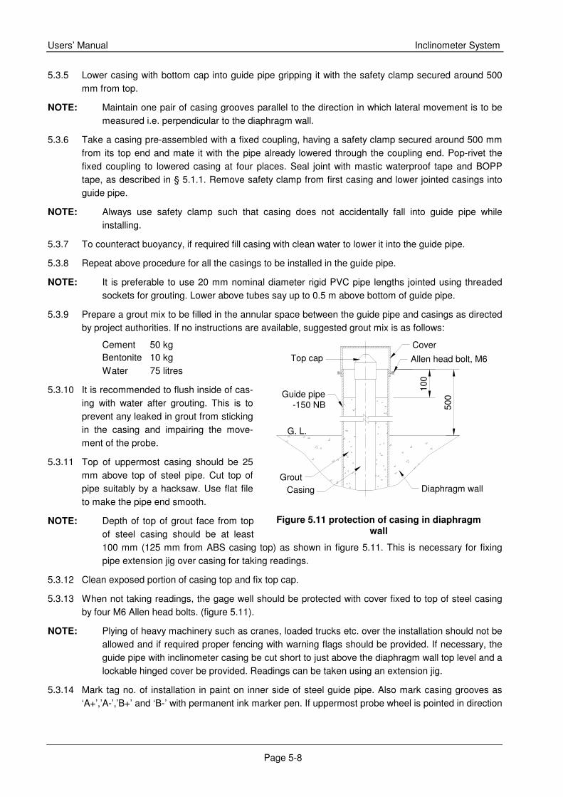
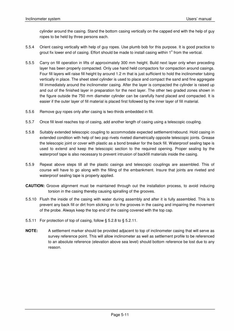
Figure 5.11 protection of casing in diaphragm wall
5.3.5 Lower casing with bottom cap into guide pipe gripping it with the safety clamp secured around 500 mm from top.
NOTE: Maintain one pair of casing grooves parallel to the direction in which lateral movement is to be measured i.e. perpendicular to the diaphragm wall.
5.3.6 Take a casing pre-assembled with a fixed coupling, having a safety clamp secured around 500 mm from its top end and mate it with the pipe already lowered through the coupling end. Pop-rivet the fixed coupling to lowered casing at four places. Seal joint with mastic waterproof tape and BOPP tape, as described in § 5.1.1. Remove safety clamp from first casing and lower jointed casings into guide pipe.
NOTE: Always use safety clamp such that casing does not accidentally fall into guide pipe while installing.
5.3.7 To counteract buoyancy, if required fill casing with clean water to lower it into the guide pipe.
5.3.8 Repeat above procedure for all the casings to be installed in the guide pipe.
NOTE: It is preferable to use 20 mm nominal diameter rigid PVC pipe lengths jointed using threaded sockets for grouting. Lower above tubes say up to 0.5 m above bottom of guide pipe.
5.3.9 Prepare a grout mix to be filled in the annular space between the guide pipe and casings as directed by project authorities. If no instructions are available, suggested grout mix is as follows:
Cement 50 kg Bentonite 10 kg Water 75 litres
5.3.10 It is recommended to flush inside of cas-ing with water after grouting. This is to prevent any leaked in grout from sticking in the casing and impairing the move-ment of the probe.
5.3.11 Top of uppermost casing should be 25 mm above top of steel pipe. Cut top of pipe suitably by a hacksaw. Use flat file to make the pipe end smooth.
NOTE: Depth of top of grout face from top of steel casing should be at least 100 mm (125 mm from ABS casing top) as shown in figure 5.11. This is necessary for fixing pipe extension jig over casing for taking readings.
5.3.12 Clean exposed portion of casing top and fix top cap.
5.3.13 When not taking readings, the gage well should be protected with cover fixed to top of steel casing by four M6 Allen head bolts. (figure 5.11).
NOTE: Plying of heavy machinery such as cranes, loaded trucks etc. over the installation should not be allowed and if required proper fencing with warning flags should be provided. If necessary, the guide pipe with inclinometer casing be cut short to just above the diaphragm wall top level and a lockable hinged cover be provided. Readings can be taken using an extension jig.
5.3.14 Mark tag no. of installation in paint on inner side of steel guide pipe. Also mark casing grooves as ‘A+’,’A-’,’B+’ and ‘B-’ with permanent ink marker pen. If uppermost probe wheel is pointed in direction
Diaphragm wall
500Guide pipe
-150 NB
G. L.
Cover
Top cap
CasingGrout
Allen head bolt, M6
100
Inclinometer system Users’ manual
Page 5-9
of the major principle plane of movement, the casing groove pointing in this direction is marked as ‘A+’. Looking down the well, directions ‘B+’,’A-’ and ‘B-’ are clockwise from ‘A’.
5.3.1. After installation check
• Check installed guide pipe for proper installation before installation of access tubing. Ensure that it is sufficiently vertical and is least distorted.
• Check installed access tubing by dummy probe (TES-AN-25/2.2) before lowering inclinometer probe.
• Ensure fixing protection cover and placing top cap after installation of inclinometer casing.
5.4. Installation in dam embankment (fill) – core section
In an embankment installation like in a dam, settlement will take place and coupling selected should be long enough to provide for anticipated settlement. TRITECH ABS telescopic coupling provides for a displacement of 150 mm. Telescopic type slip joints are usually used only in embankment, but if settlement is anticipated below a dam, they may be used in foundation also.
5.4.1 The first casing to be installed is the one with the bottom cap. Orient casing vertically with help of casing top cap and guy ropes ensuring that one groove is oriented in direction of maximum deflection. Use plumb bob for this purpose. It is good practice to grout fix lower end of casing. Effort should be made to install casing plumb within 1° from vertical. Remove casing cap and guy ropes as soon as possible because these will have to be re-used as installation continues.
NOTE: Maintain one groove orientated in the direction in which maximum deflection is expected. If the direction cannot be determined, orient north/south. Alignment must be maintained throughout the installation process, to avoid inducing torsion to the casing thereby causing spiral of the grooves.
5.4.2 Compact soil carefully around casing and let level rise to around 20 cm below top of casing.
NOTE: An inclinometer installation in embankment requires no special backfill. The soil used for embankment is compacted carefully around the casing.
CAUTION: Plastic casing in embankment installation can warp from extended exposure to hot sunlight. It should therefore be properly shielded from sunlight. Suitably cover exposed part of inclinometer casing with tarpaulin or thick black plastic sheet to protect plastic casings from unnecessary exposure to strong sunlight. Ultra violet radiation in sun rays cause faster weathering of the plastic material. Once casings are fully embedded in soil they are safe.
5.4.3 Assemble telescopic coupling using acetone for cleaning and pop rivets, mastic & BOPP tape for jointing suitably extending telescopic coupling to accommodate the expected settlement/rebound as described in § 5.1.6. Grease telescopic joint as a bond breaker for the back fill. Properly seal by mastic and BOPP tape to prevent intrusion of backfill materials inside casing.
5.4.4 Assemble next casing to telescopic coupling using procedure described above.
5.4.5 Repeat procedure till all casings and telescopic couplings are assembled. This of course will have to go along with the filling of the embankment.
NOTE: In case settlement has also to be monitored, install plate magnets as the required level is reached.
5.4.6 Flush inside of casing with water during assembly and after it is fully assembled. This is to prevent any back fill or dirt from sticking on to grooves in casing and impairing movement of probe. Always keep top of casing well plugged with top plug.
Users’ Manual Inclinometer System
Page 5-10
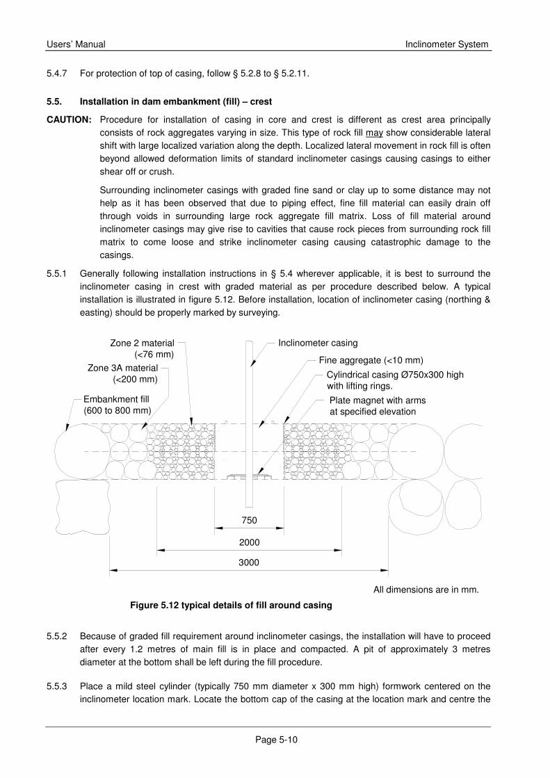
Figure 5.12 typical details of fill around casing
5.4.7 For protection of top of casing, follow § 5.2.8 to § 5.2.11.
5.5. Installation in dam embankment (fill) – crest
CAUTION: Procedure for installation of casing in core and crest is different as crest area principally consists of rock aggregates varying in size. This type of rock fill may show considerable lateral shift with large localized variation along the depth. Localized lateral movement in rock fill is often beyond allowed deformation limits of standard inclinometer casings causing casings to either shear off or crush.
Surrounding inclinometer casings with graded fine sand or clay up to some distance may not help as it has been observed that due to piping effect, fine fill material can easily drain off through voids in surrounding large rock aggregate fill matrix. Loss of fill material around inclinometer casings may give rise to cavities that cause rock pieces from surrounding rock fill matrix to come loose and strike inclinometer casing causing catastrophic damage to the casings.
5.5.1 Generally following installation instructions in § 5.4 wherever applicable, it is best to surround the inclinometer casing in crest with graded material as per procedure described below. A typical installation is illustrated in figure 5.12. Before installation, location of inclinometer casing (northing & easting) should be properly marked by surveying.
5.5.2 Because of graded fill requirement around inclinometer casings, the installation will have to proceed
after every 1.2 metres of main fill is in place and compacted. A pit of approximately 3 metres diameter at the bottom shall be left during the fill procedure.
5.5.3 Place a mild steel cylinder (typically 750 mm diameter x 300 mm high) formwork centered on the inclinometer location mark. Locate the bottom cap of the casing at the location mark and centre the
All dimensions are in mm.
Inclinometer casing
Cylindrical casing Ø750x300 highwith lifting rings.
Fine aggregate (<10 mm)
Plate magnet with armsat specified elevation
Embankment fill(600 to 800 mm)
Zone 3A material(<200 mm)
Zone 2 material(<76 mm)
3000
2000
750
Inclinometer system Users’ manual
Page 5-11
cylinder around the casing. Stand the bottom casing vertically on the capped end with the help of guy ropes to be held by three persons each.
5.5.4 Orient casing vertically with help of guy ropes. Use plumb bob for this purpose. It is good practice to grout fix lower end of casing. Effort should be made to install casing within 1o from the vertical.
5.5.5 Carry on fill operation in lifts of approximately 300 mm height. Build next layer only when preceding layer has been properly compacted. Only use hand held compactors for compaction around casings. Four fill layers will raise fill height by around 1.2 m that is just sufficient to hold the inclinometer tubing vertically in place. The sheet steel cylinder is used to place and compact the sand and fine aggregate fill immediately around the inclinometer casing. After the layer is compacted the cylinder is raised up and out of the finished layer in preparation for the next layer. The other two graded zones shown in the figure outside the 750 mm diameter cylinder can be carefully hand placed and compacted. It is easier if the outer layer of fill material is placed first followed by the inner layer of fill material.
5.5.6 Remove guy ropes only after casing is two-thirds embedded in fill.
5.5.7 Once fill level reaches top of casing, add another length of casing using a telescopic coupling.
5.5.8 Suitably extended telescopic coupling to accommodate expected settlement/rebound. Hold casing in extended condition with help of two pop rivets riveted diametrically opposite telescopic joints. Grease the telescopic joint or cover with plastic as a bond breaker for the back fill. Waterproof sealing tape is used to extend and keep the telescopic section to the required opening. Proper sealing by the waterproof tape is also necessary to prevent intrusion of backfill materials inside the casing.
5.5.9 Repeat above steps till all the plastic casings and telescopic couplings are assembled. This of course will have to go along with the filling of the embankment. Insure that joints are riveted and waterproof sealing tape is properly applied.
CAUTION: Groove alignment must be maintained through out the installation process, to avoid inducing torsion in the casing thereby causing spiralling of the grooves.
5.5.10 Flush the inside of the casing with water during assembly and after it is fully assembled. This is to prevent any back fill or dirt from sticking on to the grooves in the casing and impairing the movement of the probe. Always keep the top end of the casing covered with the top cap.
5.5.11 For protection of top of casing, follow § 5.2.8 to § 5.2.11.
NOTE: A settlement marker should be provided adjacent to top of inclinometer casing that will serve as survey reference point. This will allow inclinometer as well as settlement profile to be referenced to an absolute reference (elevation above sea level) should bottom reference be lost due to any reason.
Inclinometer System Users’ manual
Page 6-1
A+ (A)
A- (C)
B+ (B)B- (D)
6. Preparation for and obtaining readings
For detailed instructions, refer to TES-DI-53 INS inclinometer data-logger operating manual # WI 6002.80.
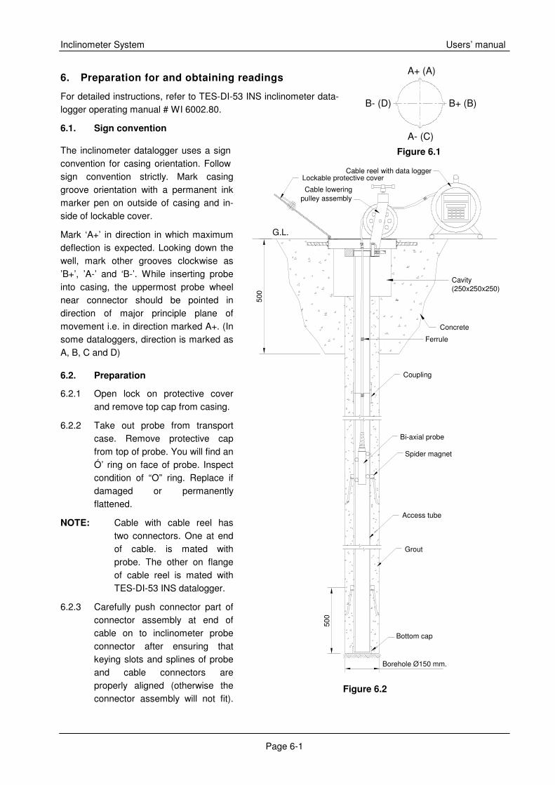
6.1. Sign convention
The inclinometer datalogger uses a sign convention for casing orientation. Follow sign convention strictly. Mark casing groove orientation with a permanent ink marker pen on outside of casing and in-side of lockable cover.
Mark ‘A+’ in direction in which maximum deflection is expected. Looking down the well, mark other grooves clockwise as ’B+’, ’A-’ and ‘B-’. While inserting probe into casing, the uppermost probe wheel near connector should be pointed in direction of major principle plane of movement i.e. in direction marked A+. (In some dataloggers, direction is marked as A, B, C and D)
6.2. Preparation
6.2.1 Open lock on protective cover and remove top cap from casing.
6.2.2 Take out probe from transport case. Remove protective cap from top of probe. You will find an Ó’ ring on face of probe. Inspect condition of “O” ring. Replace if damaged or permanently flattened.
NOTE: Cable with cable reel has two connectors. One at end of cable. is mated with probe. The other on flange of cable reel is mated with TES-DI-53 INS datalogger.
6.2.3 Carefully push connector part of connector assembly at end of cable on to inclinometer probe connector after ensuring that keying slots and splines of probe and cable connectors are properly aligned (otherwise the connector assembly will not fit).
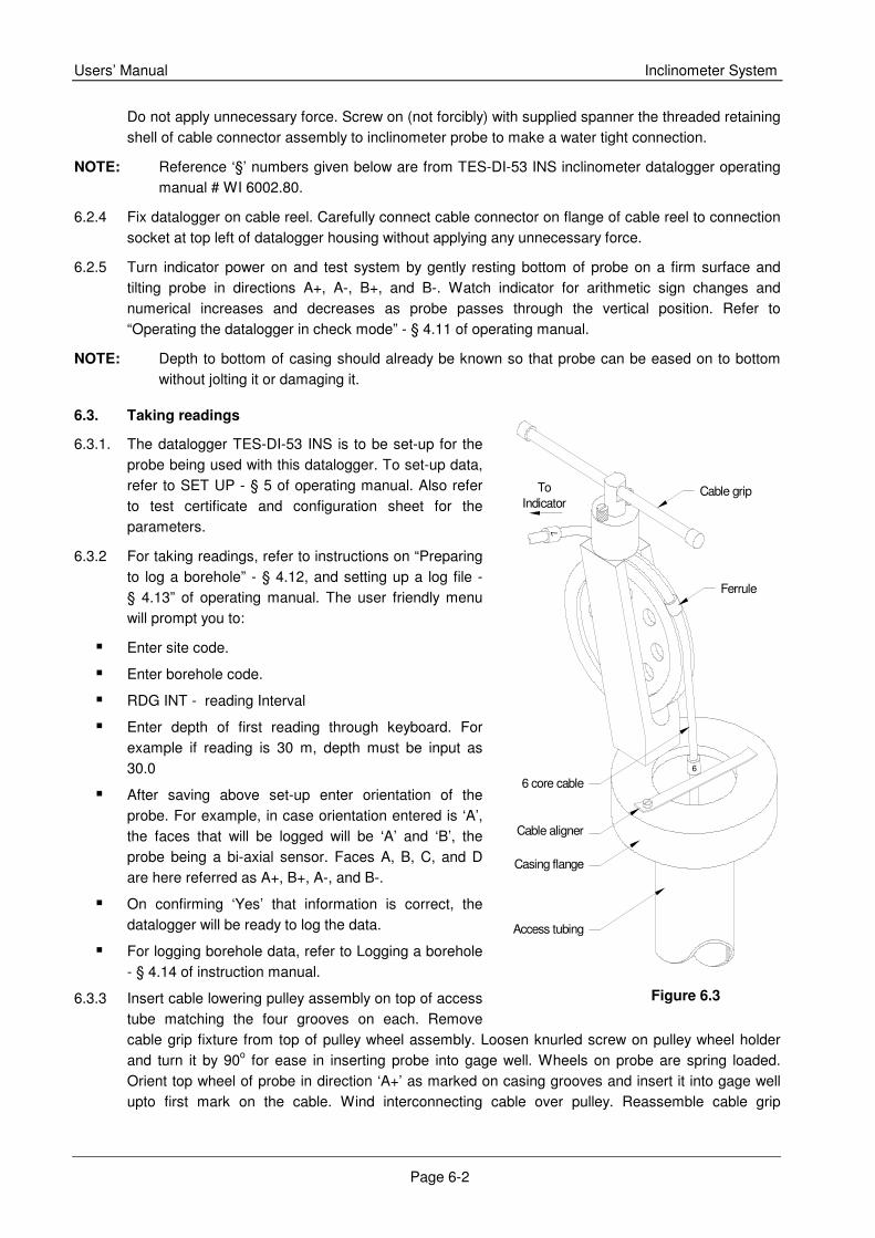
Borehole Ø150 mm.
Cable reel with data logger
G.L.
pulley assemblyCable lowering
Lockable protective cover
Bottom cap
Grout
Access tube
Coupling
Spider magnet
Concrete
Cavity(250x250x250)
Bi-axial probe
Ferrule
500
500
Figure 6.2
Figure 6.1
Users’ Manual Inclinometer System
Page 6-2
Do not apply unnecessary force. Screw on (not forcibly) with supplied spanner the threaded retaining shell of cable connector assembly to inclinometer probe to make a water tight connection.
NOTE: Reference ‘§’ numbers given below are from TES-DI-53 INS inclinometer datalogger operating manual # WI 6002.80.
6.2.4 Fix datalogger on cable reel. Carefully connect cable connector on flange of cable reel to connection socket at top left of datalogger housing without applying any unnecessary force.
6.2.5 Turn indicator power on and test system by gently resting bottom of probe on a firm surface and tilting probe in directions A+, A-, B+, and B-. Watch indicator for arithmetic sign changes and numerical increases and decreases as probe passes through the vertical position. Refer to “Operating the datalogger in check mode” - § 4.11 of operating manual.
NOTE: Depth to bottom of casing should already be known so that probe can be eased on to bottom without jolting it or damaging it.
6.3. Taking readings
6.3.1. The datalogger TES-DI-53 INS is to be set-up for the probe being used with this datalogger. To set-up data, refer to SET UP - § 5 of operating manual. Also refer to test certificate and configuration sheet for the parameters.
6.3.2 For taking readings, refer to instructions on “Preparing to log a borehole” - § 4.12, and setting up a log file - § 4.13” of operating manual. The user friendly menu will prompt you to:
� Enter site code.
� Enter borehole code.
� RDG INT - reading Interval
� Enter depth of first reading through keyboard. For example if reading is 30 m, depth must be input as 30.0
� After saving above set-up enter orientation of the probe. For example, in case orientation entered is ‘A’, the faces that will be logged will be ‘A’ and ‘B’, the probe being a bi-axial sensor. Faces A, B, C, and D are here referred as A+, B+, A-, and B-.
� On confirming ‘Yes’ that information is correct, the datalogger will be ready to log the data.
� For logging borehole data, refer to Logging a borehole - § 4.14 of instruction manual.
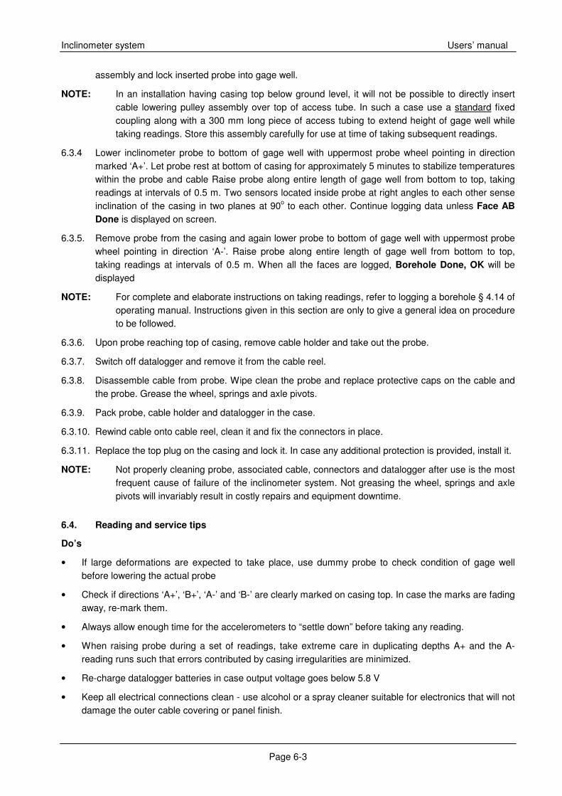
6.3.3 Insert cable lowering pulley assembly on top of access tube matching the four grooves on each. Remove cable grip fixture from top of pulley wheel assembly. Loosen knurled screw on pulley wheel holder and turn it by 90o for ease in inserting probe into gage well. Wheels on probe are spring loaded. Orient top wheel of probe in direction ‘A+’ as marked on casing grooves and insert it into gage well upto first mark on the cable. Wind interconnecting cable over pulley. Reassemble cable grip
6 core cable
Cable aligner
Access tubing
IndicatorCable gripTo
Casing flange
6
7
Ferrule
Figure 6.3
Inclinometer system Users’ manual
Page 6-3
assembly and lock inserted probe into gage well.
NOTE: In an installation having casing top below ground level, it will not be possible to directly insert cable lowering pulley assembly over top of access tube. In such a case use a standard fixed coupling along with a 300 mm long piece of access tubing to extend height of gage well while taking readings. Store this assembly carefully for use at time of taking subsequent readings.
6.3.4 Lower inclinometer probe to bottom of gage well with uppermost probe wheel pointing in direction marked ‘A+’. Let probe rest at bottom of casing for approximately 5 minutes to stabilize temperatures within the probe and cable Raise probe along entire length of gage well from bottom to top, taking readings at intervals of 0.5 m. Two sensors located inside probe at right angles to each other sense inclination of the casing in two planes at 90o to each other. Continue logging data unless Face AB
Done is displayed on screen.
6.3.5. Remove probe from the casing and again lower probe to bottom of gage well with uppermost probe wheel pointing in direction ‘A-’. Raise probe along entire length of gage well from bottom to top, taking readings at intervals of 0.5 m. When all the faces are logged, Borehole Done, OK will be displayed
NOTE: For complete and elaborate instructions on taking readings, refer to logging a borehole § 4.14 of operating manual. Instructions given in this section are only to give a general idea on procedure to be followed.
6.3.6. Upon probe reaching top of casing, remove cable holder and take out the probe.
6.3.7. Switch off datalogger and remove it from the cable reel.
6.3.8. Disassemble cable from probe. Wipe clean the probe and replace protective caps on the cable and the probe. Grease the wheel, springs and axle pivots.
6.3.9. Pack probe, cable holder and datalogger in the case.
6.3.10. Rewind cable onto cable reel, clean it and fix the connectors in place.
6.3.11. Replace the top plug on the casing and lock it. In case any additional protection is provided, install it.
NOTE: Not properly cleaning probe, associated cable, connectors and datalogger after use is the most frequent cause of failure of the inclinometer system. Not greasing the wheel, springs and axle pivots will invariably result in costly repairs and equipment downtime.
6.4. Reading and service tips
Do’s
• If large deformations are expected to take place, use dummy probe to check condition of gage well before lowering the actual probe
• Check if directions ‘A+’, ‘B+’, ‘A-’ and ‘B-’ are clearly marked on casing top. In case the marks are fading away, re-mark them.
• Always allow enough time for the accelerometers to “settle down” before taking any reading.
• When raising probe during a set of readings, take extreme care in duplicating depths A+ and the A- reading runs such that errors contributed by casing irregularities are minimized.
• Re-charge datalogger batteries in case output voltage goes below 5.8 V
• Keep all electrical connections clean - use alcohol or a spray cleaner suitable for electronics that will not damage the outer cable covering or panel finish.
Users’ Manual Inclinometer System
Page 6-4
• Replace probe wheels and axles if they become wobbly or sticky.
• Constantly check conditions of “O” ring on probe face to maintain a watertight seal.
• Keep protective plugs in place on all electric outlets to prevent physical damage or liquids spilling into them.
Do not’s:
• Hard bumps to probe can misalign and/or break the accelerometers or break internal electrical connections.
• Hard bumps to indicator can dislodge internal batteries, break electrical connections, shift LCD readouts or rupture the watertight case seals.
• Exposing indicator to direct sunlight for long periods of time can raise internal temperatures beyond tolerance level of the unit and may crack circuit boards or overheat the batteries.
• Bending connecting cable over sharp objects or walking on it can sever internal conductors or puncture the outer waterproof coating.
• Dragging cable through the cable brake/holder on the pulley mechanism may damage or move the copper ferrules.
• The batteries should not be overcharged. Maximum recharge time is 16 hours or two times the period in operation since the last recharge. Do not attempt to recharge internal batteries or operate from an external power source when the temperature of the indicator is below 5°C.
NOTE: The inclinometer system is like other delicate equipment and its use requires common sense and reasonable care!

Inclinometer System Users’ manual
TABL E O F CO NTENTS
1. INTRODUCTION 1-1
1.1. Displacement measurement 1-1
1.2. Casing storage 1-1
1.3. Conventions used in this manual 1-1
1.4. General information 1-1
1.5. How to use this manual 1-2
2. INCLINOMETER SYSTEM 2-1
2.1. Operating principle 2-1
2.2. General description 2-1
2.2.1. TES-AN-25/1 access casing and fittings 2-1
2.2.2. TES-AN-25/2 tilt sensing probe 2-3
2.2.3. TES-AN-20/3 interconnecting cable with reel and cable holder 2-4
2.2.4. TES-AN-25/4 data logger 2-4
3. SYSTEM SPECIFICATIONS 3-1
3.1. Probe 3-1
3.2. Cable reel 3-1
3.3. Casing and fittings 3-1
3.4. Datalogger 3-1
3.5. Ancillary equipment 3-1
4. TOOLS & ACCESSORIES REQUIRED FOR INSTALLATION 4-1
5. INSTALLATION OF CASING 5-1
5.1. Preparation of casing before installation 5-1
5.2. Installation in borehole 5-4
5.3. Installation in diaphragm wall or pile 5-7
5.3.1. After installation check 5-9
5.4. Installation in dam embankment (fill) – core section 5-9
5.5. Installation in dam embankment (fill) – crest 5-10
6. PREPARATION FOR AND OBTAINING READINGS 6-1
6.1. Sign convention 6-1
6.2. Preparation 6-1
6.3. Taking readings 6-2
6.4. Reading and service tips 6-3