Terrasoar 9th intake thesis Geoff Wardle
205
CRANFIELD UNIVERSITY SCHOOL OF ENGINEERING MSc THESIS Academic years 2003 – 2006 GEOFFREY A WARDLE MSc CEng Airframe Design Lead. WING DESIGN AND SYSTEMS INTEGRATION FOR THE TERRASOAR HALE UAV GROUP DESIGN PROJECT Incorporating: - Conceptual design of the complete aircraft and the wing: Major Component layout and detailed design of the wing: Manufacture: and Structural qualification assessment proposal. Supervisor: Mr Phillip Stocking November 2005 This thesis is submitted in partial (40%) fulfilment of the requirements for the degree of Master of Science in Aircraft Engineering. Cranfield University 2005. All rights reserved. No part of this publication may be reproduced without the written permission of the copyright holder.
-
Upload
geoffrey-wardle-msc-msc-snrmaiaa -
Category
Documents
-
view
118 -
download
0
Transcript of Terrasoar 9th intake thesis Geoff Wardle

CRANFIELD UNIVERSITY
SCHOOL OF ENGINEERING
MSc THESIS
Academic years 2003 – 2006
GEOFFREY A WARDLE MSc CEng Airframe Design Lead.
WING DESIGN AND SYSTEMS INTEGRATION FOR THE
TERRASOAR HALE UAV GROUP DESIGN PROJECT
Incorporating: - Conceptual design of the complete aircraft and the
wing: Major Component layout and detailed design of the wing:
Manufacture: and Structural qualification assessment proposal.
Supervisor: Mr Phillip Stocking
November 2005
This thesis is submitted in partial (40%) fulfilment of the requirements for the degree of Master of Science
in Aircraft Engineering.
Cranfield University 2005. All rights reserved. No part of this publication may be reproduced without the
written permission of the copyright holder.

TERRASOAR BAE Systems / Cranfield University G. A. Wardle MSc CEng MSc Group Design Project Thesis.
i
Theses “Health” Warning
This thesis has been assessed as of satisfactory standard for the award of a Master of
Science degree in Aircraft Engineering. This thesis covers part of the assessment
concerned with the Individual Research Project. Readers must be aware that the work
contained is not necessarily 100% correct, and caution should be exercised if this thesis
or the data it contains is being used for future work. If in doubt, please refer to the
supervisor named in the thesis, or the Aerospace Engineering Group.
TERRASOAR BAE Systems / Cranfield University G. A. Wardle MSc CEng MSc Group Design Project Thesis.
ii
Abstract.
This thesis covers the group design project of the 2003 9th
Intake of the Cranfield
University part-time Master of Science Degree in Aircraft Engineering, focusing on the
work of the author as part of the project team.
The objective of the Terrasoar project was to design, manufacture, ground test, and fly a
High Altitude Long Endurance small low cost Unmanned Air Vehicle with CAA
certification for flight at 10,000ft (3,048m) in uncontrolled airspace, with an endurance of
5hours, and payload of 5kg. However although CAA certification was not possible at this
time all of the structures and methodology is in place, and this aircraft will be certificated
to fly within controlled airspace.
The final solution has been to design and manufacture an aircraft which will meet a set of
less demanding missions criteria up to an altitude of 400ft (121.92m), and an endurance
of 4.5hours, which was within the scope of the project. This aircraft has the capability of
being modified with additional systems, new outboard wing, and a new engine, to fly at
the original target altitude. These modifications could reasonably be considered for a
future intake to the part – time Cranfield University / BAE Systems Aircraft Engineering
MSc course, and pursuit of eventual certification is a realistic goal as the route to full
certification has been established by the 9th
intake.
This thesis covers the author‟s contribution to the conceptual design phase and
configuration investigation, and the author‟s role as the Airframe Lead and wing designer
of the final Terrasoar configuration, which has lead to the manufacturable design solution
which meets the current missions identified for this aircraft.
At the time of writing Terrasoar tooling OML (Outer Mould Line) has been
manufactured for all major airframe units, the FCS has been test flown and the engine has
been ground tested and the final assembly jig and tool has been designed. The materials
and other long lead time items are due to be ordered and manufacture is due to begin in
February 2006, with ground testing in June and first flight targeted for July or September
2006.
This thesis covers the wing design maturation up to the 30th
November 2006 when
authority for further detail design changes, such as any minor manufacturing easement
changes of the wing design was handed over to BAE Systems Warton / Samlesbury New
Business unit, and effectively the author passed over responsibility for the design to BAE
Systems.

TERRASOAR BAE Systems / Cranfield University G. A. Wardle MSc CEng MSc Group Design Project Thesis.
iii
Acknowledgements
Firstly I would like to thank BAE Systems for allowing me to participate in this MSc
course, in particular my thanks are offered to Andy Bruce who supported my application
for the course and maintained an interest throughout even during my movements around
the Joint Strike Fighter / F-35 Integrated Product Team.
From Cranfield University, School of Engineering, Aerospace Engineering Group I wish
to thank Mr Philip Stocking whose strong chairmanship and guidance in the face of
external forces has ensured that this project did not veer off course.
I would like to thank BAE Systems Manufacturing Technology team in particular Mr
Robert Cross and Mr Craig Carr (who was originally a member of the 9th
intake) for their
time and energy in helping the team in developing a manufacturing methodology which
will ensure this aircraft is built.
Particular thanks go to my colleagues from the 9th
intake of the Aircraft Engineering MSc
course:-
Paul Gilligan James Pennington Bob Currie
Damian Adams Alan Barnes Dave Baird
Rob Sneddon Vernon Hind Craig Carr
Jon Baggaley Rachael Cunliffe Rob Cunliffe
Emma Bradley.
All of who participated towards the successful completion of the Terrasoar project with
varying degrees of theoretical and practical work. Additionally I would like to thank Mr
Ian Isenburge of JSF IT support for transferring the CATIA models and documents I
crated at BAE SYSTEMS on to disc enabling me write this thesis at home.
Finally I would like to thank my partner for encouragement understanding, coffee and
food throughout the duration of this particularly demanding course.

TERRASOAR BAE Systems / Cranfield University G. A. Wardle MSc CEng MSc Group Design Project Thesis.
iv
Contents Page
Theses “Health” Warning i
Abstract ii
Acknowledgements iii
Contents iv
Figures vii
Tables‟ xiv
Glossary xv
1.0 Introduction 1
1.1. Project Statement of Work 3
1.2. 9th
Intake Roles and responsibilities 11
1.3. Design methodology (Design Manual) 14
2.0 Requirements capture 22
2.1. Aircraft design specification document divergence 23
2.2. Revision of mission requirement specification 29
3.0 Airframe Conceptual Design Phase 36
3.1 Airframe configuration submissions and design decisions 39
3.2 Airframe configuration down selection 76
4.0 Terrasoar wing design 84
4.1 Structural definition for wing design 85
4.2 Review of 5th
intake wing design 89
4.3 (A) Status wing layout and structural definition for PDR 93
4.4 (A) Status wing layout and structural definition post PDR 96

TERRASOAR BAE Systems / Cranfield University G. A. Wardle MSc CEng MSc Group Design Project Thesis.
v
4.5 (B) Status wing layout and structural definition for CDR 101
4.6 (C) Status revised CDR wing layout incorporating stressing 109
4.7 Detailed design for BAE Systems manufacture 112
5.0 Wing interface joint concept design 117
5.1 (A) Status PDR Interface Joint Trades 117
5.1.1 Post PDR (A) Status design study 117
5.1.2 (A) Status wing to empennage boom joints 118
5.1.3 (A) Status wing to fuselage interface joint 119
5.1.4 (A) Status inboard to outboard wing joints 120
5.2 (B) Status interface joint design studies 123
5.2.1 (B) Status wing to fuselage joint for CDR 124
5.2.2 (B) Status common wing and boom interface joint for CDR 124
5.3 (C) Status interface joint maturation for manufacture 127
6.0 Flight control surface and systems integration 129
6.1 (A) Status aileron attachment studies 129
6.2 (B) Status aileron attachment for CDR 131
6.3 (C) Status aileron attachment for manufacture 132
6.4 (A) Status aileron design studies 133
6.5 (B) Status aileron design 135
6.6 (C) Status aileron design for CDR 136
6.7 (C) Status FCS systems integration COTS 137
7.0 Materials and manufacturing methodology 141
7.1 Materials selection and aircraft weight 141

TERRASOAR BAE Systems / Cranfield University G. A. Wardle MSc CEng MSc Group Design Project Thesis.
vi
7.2 Manufacturing methods and tool design 143
7.3 Structural test and qualification proposal 145
8.0 Conclusions 163
9.0 Further work required 163
10.0 References 164
Appendices:-
A-1: - Wing weight tables 166
A-2: - Major wing component isometric view sketch book
after signing off by the customer: structure engineering:
and manufacturing 170
A-3: - Post CDR Wing sign – off document 180
A-4: - Terrasoar wing major component dimensioned drawings 187
TERRASOAR BAE Systems / Cranfield University G. A. Wardle MSc CEng MSc Group Design Project Thesis.
vii
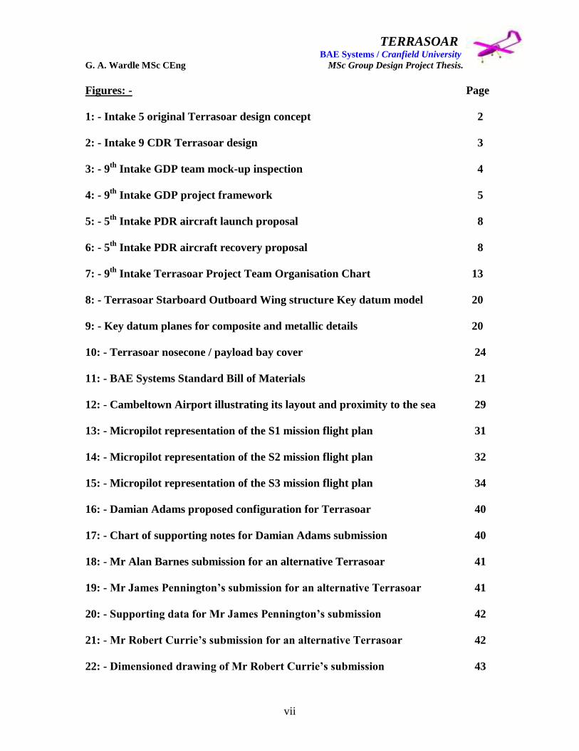
Figures: - Page
1: - Intake 5 original Terrasoar design concept 2
2: - Intake 9 CDR Terrasoar design 3
3: - 9th
Intake GDP team mock-up inspection 4
4: - 9th
Intake GDP project framework 5
5: - 5th
Intake PDR aircraft launch proposal 8
6: - 5th
Intake PDR aircraft recovery proposal 8
7: - 9th
Intake Terrasoar Project Team Organisation Chart 13
8: - Terrasoar Starboard Outboard Wing structure Key datum model 20
9: - Key datum planes for composite and metallic details 20
10: - Terrasoar nosecone / payload bay cover 24
11: - BAE Systems Standard Bill of Materials 21
12: - Cambeltown Airport illustrating its layout and proximity to the sea 29
13: - Micropilot representation of the S1 mission flight plan 31
14: - Micropilot representation of the S2 mission flight plan 32
15: - Micropilot representation of the S3 mission flight plan 34
16: - Damian Adams proposed configuration for Terrasoar 40
17: - Chart of supporting notes for Damian Adams submission 40
18: - Mr Alan Barnes submission for an alternative Terrasoar 41
19: - Mr James Pennington‟s submission for an alternative Terrasoar 41
20: - Supporting data for Mr James Pennington‟s submission 42
21: - Mr Robert Currie‟s submission for an alternative Terrasoar 42
22: - Dimensioned drawing of Mr Robert Currie‟s submission 43
TERRASOAR BAE Systems / Cranfield University G. A. Wardle MSc CEng MSc Group Design Project Thesis.
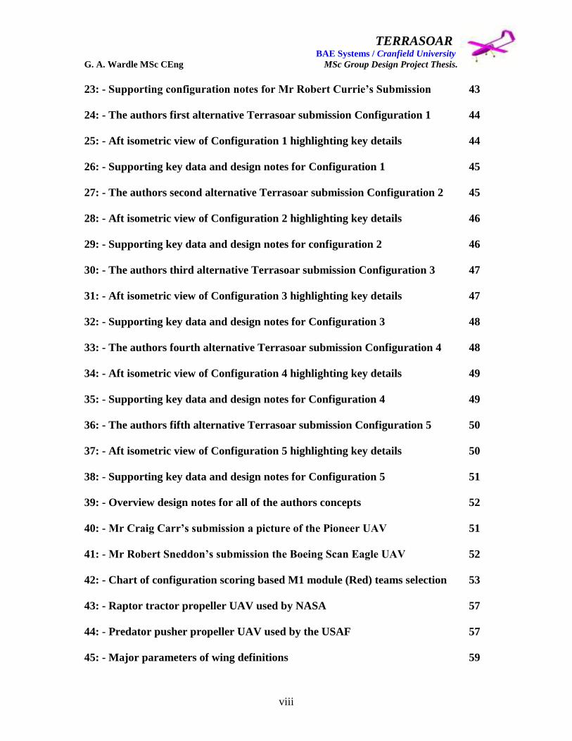
viii
23: - Supporting configuration notes for Mr Robert Currie‟s Submission 43
24: - The authors first alternative Terrasoar submission Configuration 1 44
25: - Aft isometric view of Configuration 1 highlighting key details 44
26: - Supporting key data and design notes for Configuration 1 45
27: - The authors second alternative Terrasoar submission Configuration 2 45
28: - Aft isometric view of Configuration 2 highlighting key details 46
29: - Supporting key data and design notes for configuration 2 46
30: - The authors third alternative Terrasoar submission Configuration 3 47
31: - Aft isometric view of Configuration 3 highlighting key details 47
32: - Supporting key data and design notes for Configuration 3 48
33: - The authors fourth alternative Terrasoar submission Configuration 4 48
34: - Aft isometric view of Configuration 4 highlighting key details 49
35: - Supporting key data and design notes for Configuration 4 49
36: - The authors fifth alternative Terrasoar submission Configuration 5 50
37: - Aft isometric view of Configuration 5 highlighting key details 50
38: - Supporting key data and design notes for Configuration 5 51
39: - Overview design notes for all of the authors concepts 52
40: - Mr Craig Carr‟s submission a picture of the Pioneer UAV 51
41: - Mr Robert Sneddon‟s submission the Boeing Scan Eagle UAV 52
42: - Chart of configuration scoring based M1 module (Red) teams selection 53
43: - Raptor tractor propeller UAV used by NASA 57
44: - Predator pusher propeller UAV used by the USAF 57
45: - Major parameters of wing definitions 59
TERRASOAR BAE Systems / Cranfield University G. A. Wardle MSc CEng MSc Group Design Project Thesis.
ix
46: - Induced drag factor as a function of taper ratio for different wing AR 60
47: - Example of geometric twist in a tapered wing 63
48: - Comparison of high-wing, mid-wing, and low wing configurations 64
49: - Characteristics of an airfoil section 66
50: - Airfoil forces and moments 69
51: - Airfoil centre of pressure 69
52: - Aerodynamic centre 1 70
53: - Aerodynamic centre 2 70
54: - NACA 4412 chart analysis 1 71
55: - NACA 4412 chart analysis 2 72
56: - NACA 4412 chart analysis 3 73
57: - Wartmann FX 63 – 137 airfoil 75
58: - Aircraft reference axes and corresponding aerodynamic moments 76
59: - Alternative Terrasoar configuration 6 (A) fwd quarter 77
60: - Alternative Terrasoar configuration 6 (A) aft quarter 77
61: - Author‟s supporting data for alternative Terrasoar configuration 6(A) 78
62: - Alternative Terrasoar configuration 7 isometric view 79
63: - Alternative Terrasoar configuration 7 external features 1 79
64: - Alternative Terrasoar configuration 7 external features 2 80
65: - Alternative Terrasoar configuration 7 fuselage internal features 81
66: - Alternative Terrasoar configuration 7 wing internal features 82
67: - Author‟s supporting data for alternative Terrasoar configuration 7 83

TERRASOAR BAE Systems / Cranfield University G. A. Wardle MSc CEng MSc Group Design Project Thesis.
x
68: - Sketch of the final down selected modified Terrasoar configuration 84
69: - Typical I spar constriction 86
70: - Typical Rib construction 87
71: - Typical Stringer stiffened and stressed skin wing layouts 87
72: - Major fixed aerodynamic surface airfoil selection (5th
Intake) 89
73: - Wing dihedral on outboard wing panels (5th
Intake) 89
74: - Aerodynamic twist in wing panels (5th
Intake) 90
75: - Major fixed aerodynamic surfaces (5th
Intake) 90
76: - Proposed wing manufacturing methodology (5th
Intake) 91
77: - Vehicle transportation breaks (5th
Intake) 91
78: - (A) Status PDR wing general arrangement model 93
79: - (A) Status PDR internal structure model showing key features 94
80: - (A) Status PDR internal structure of the outboard wing 95
81: - (A) Status PDR wing to fuselage location model 95
82: - (A) Status PDR wing / fuselage attachment rib 96
83: - (A) Status Post PDR Study wing G.A. model external configuration 99
84: - (A) Status Post PDR Study wing G.A. model internal configuration 99
85: - (A) Status Post PDR Study Outboard wing with skin construction detail 100
86: - (A) Status Post PDR Study Outboard wing with spar construction detail 100
87: - Interim Maturation wing external features 102
88: - Interim Maturation wing internal features 103
89: - Actuator integration concept 104
90: - (B) Status CDR Revision wing external configuration 105

TERRASOAR BAE Systems / Cranfield University G. A. Wardle MSc CEng MSc Group Design Project Thesis.
xi
91: - (B) Status CDR Revision wing internal configuration 105
92: - (B) Status CDR Revision outboard wing external detail 106
93: - (B) Status CDR Revision outboard wing internal detail 106
94: - (B) Status CDR Revision aileron integration 107
95: - (C) Status Post CDR wing design with stress sizing at sign off 110
96: - (C) Status Post CDR centre wing skin at sign off 110
97: - (C) Status Post CDR centre wing structure at sign off 111
98: - (C) Status Post CDR outboard wing exterior at sign off 111
99: - (C) Status Post CDR outboard wing interior at sign off 112
100: - Manufacturing maturation of signed off centre wing structure 113
101: - Manufacturing maturation of signed off centre top wing skin 113
102: - Manufacturing maturation of signed off centre lower wing skin 114
103: - Manufacturing maturation of signed off outboard lower wing skin 114
104: - Manufacturing maturation of signed off outboard top wing skin 115
105: - Manufacturing maturation of signed off outboard wing structure 115
106: - (C) Status aileron structure 116
107: - (A) Status wing to empennage joint concept 2 118
108: - Post PDR (A) Status design study wing / fuselage joint concept 1 120
109: - (A) Status Inboard / Outboard wing joint (authors) concept 1 121
110: - (A) Status Inboard / Outboard wing joint (authors) concept 2 122
111: - (A) Status Inboard / Outboard wing joint (Peter Hamilton) concept 3 123
112: - (B) Status wing / fuselage joint presented at CDR (James Pennington) 124
113: - (B) Status common outboard wing / empennage joint (James Pennington) 125
TERRASOAR BAE Systems / Cranfield University G. A. Wardle MSc CEng MSc Group Design Project Thesis.
xii
114: - (C) Status common outboard wing / empennage joint (author) 126
115: - The basic forces acting on an aircraft in flight 126
116: - (C) Status common wing joint weight reduction proposal (Pete Hamilton) 127
117: - Manufacturing maturation of the common interface joint 127
118: - Manufacturing maturation of the wing / fuselage joint 128
119: - Post PDR (A) Status design study wing / aileron interface 130
120: - General arrangement of a 2 hinge flap illustrating the floating hinge 130
121: - (B) Status wing / aileron interface presented at CDR 131
122: - Post CDR wing / aileron interface for manufacture 132
123: - Spigot support lug integration 132
124: - Pre PDR (A) Status David Baird first aileron concept 133
125: - Pre PDR (A) Status David Bird second aileron concept 133
126: - PDR (A) Status David Bird third aileron concept 134
127: - (B) Status Aileron design for Post PDR wing design studies 135
128: - (C) Status Aileron design for CDR 136
129: - Schematic of Terrasoar FSC 137
130: - FCS aileron wiring and connections in the centre wing interface 138
131: - FCS aileron wiring in the outboard wing 138
132: - Actuator wiring channels in the outboard wing 139
133: - Aileron actuator installation 139
134: - Aileron actuator drive mechanism 140
135: - Aileron horns and actuator drive rods 140
136: - First outboard wing skin re-stressing 141

TERRASOAR BAE Systems / Cranfield University G. A. Wardle MSc CEng MSc Group Design Project Thesis.
xiii
137: - First inboard wing skin re-stressing 142
138: - Second outboard wing skin re-stressing 142
139: - Second inboard wing skin re-stressing 143
140: - Terrasoar wing centre section tool design 144
141: - Manufacturing spar changes 144
142: - Building block test plan 146
143: - Materials qualification testing 151
144: - Component testing 153
145: - Tension patch full scale wing testing 160
146: - Loading frame full scale wing testing 161
TERRASOAR BAE Systems / Cranfield University G. A. Wardle MSc CEng MSc Group Design Project Thesis.
xiv
Tables: - Page
1: - The disparity between the Projected and Actual Project Timescales 10
2: - Documentation requirements for the S1 Mission 31
3: - Documentation requirements for the S2 Mission 33
4: - Documentation requirements for the S3 Mission 35
5: - Configuration decision making summary table 54
6: - Stress data for the Terrasoar post CDR wing using raped skin 109
7: - Effect of FVP on mechanical properties of test laminates 148
8: - ASTM Shear coupon composite shear tests 148
9: - CDR wing submission wing weight table based on Phenolic fibreglass and
R63.80 foam core and Styrofoam and Al 2024-T351 densities 166
10: - Post CDR sign - off wing redesign weight table based on revised fibreglass
and R63.80 foam core and Tricast 6 and Al 2024-T351 densities 168
TERRASOAR BAE Systems / Cranfield University G. A. Wardle MSc CEng MSc Group Design Project Thesis.
xv
Glossary: -
AAC Air Combat Command
ADR Air Data Relay
AFB Air Force Base
AIAA American Institute of Aeronautics and Astronautics
AT Aerial Target
AV Air Vehicle
ATDC Advanced Technology Demonstration Centre
BDA Battle Damage Assessment
BM Bending Moment
CAD Computer Aided Design
CATA Control, Automation and Task Allocation
CCD Charged Couple Device
CDL Common Data Link
C of G Centre of Gravity
CFC Carbon Fibre Composite
CFD Computational Fluid Dynamics
DARO Defence Airborne Reconnaissance Office
DARPA Defence Advance Research Projects Agency
DERA Defence Evaluation and Research Agency
D o D Department of Defence
EO Electro - Optical
ERAST Environmental Research Aircraft and Sensor Technology

TERRASOAR BAE Systems / Cranfield University G. A. Wardle MSc CEng MSc Group Design Project Thesis.
xvi
EW Electronic Warfare
ESDU Engineering Science Data Unit
FLIR Forward Looking Infrared
FEA Finite Element Analysis
G.A. General Arrangement (Drawing or Model)
GA General Atomics Aeronautical Systems
GCS Ground Control Station
GDP Group Design Project
GDT Ground Data Terminal
GPS Global Positioning System
GRP Glass Fibre Reinforced Plastics
GSE Ground Support Equipment
HALE High Altitude Long Endurance (= or > 30,000ft)
IFF Information Friend or Foe
INS Inertial Navigation System
IML Inner Mould Lines (internal surface limits)
LAD Landing Assist Device
LASS Low Altitude Surveillance System
LOS Line Of Sight
MAE Medium Altitude Endurance
MALE Medium Altitude Long Endurance (< 30,000ft)
NACA National Advisory Committee on Aviation
NASA National Aeronautics and Space Administration

TERRASOAR BAE Systems / Cranfield University G. A. Wardle MSc CEng MSc Group Design Project Thesis.
xvii
NOLO No Live Operator
OML Outer Mould Lines (external surface limits)
OTH Over The Horizon
RAF Royal Air Force
RPV Remote Piloted Vehicle
RN Royal Navy
SEAD Suppression of Enemy Air Defences
SFC Specific Fuel Consumption
UAV Unmanned Air Vehicle
UCAV Unmanned Combat Air Vehicle
UHF Ultra High Frequency
URAV Unmanned Reconnaissance Aerial Vehicle
USAF United States Air Force
USCG United States Coast Guard

TERRASOAR BAE Systems / Cranfield University G. A. Wardle MSc CEng MSc Group Design Project Thesis.
1
1: - Introduction.
The UAV or Unmanned Aerial Vehicle is an aircraft that is specifically designed to fly an
entire mission profile in the same way as a manned operational aircraft would i.e. take-off
fly to somewhere to perform a specific task, return to base, and land, with the exception
of the pilot being aboard. These aircraft were known as remotely piloted vehicles
(RPV‟s) until the 1980‟s, because they were primarily directed by an external source of
control either on the ground or in an accompanying aircraft. However many modern
vehicles are no longer remotely controlled and are pre-programmed to operate
autonomously and the development of an operational UAV is the subject of this thesis.
While UAV‟s are not designed to be expendable meaning that the end user services do
not intend to lose them every time they are sent on a mission, they are, in the terminology
of the United States of America‟s Department of Defence “attritable”. This means that a
commander can afford to lose one through attrition, especially when the alternative is the
loss of a manned aircraft or an aircrew. Although UAV‟s do not put pilots lives at risk in
uncontrolled airspace they have the potential to put manned aircraft from light aircraft to
airliners and populated area at risk from air to air collision or crashing, therefore very few
are FAA or CAA certified to fly outside closed government ranges and testing
establishments. Also because the UAV is unmanned there is a misconception that they
are cheap (mostly founded on the belief that they are like the cruise missile and
expendable), although generally they are less expensive than manned aircraft and the cost
of fully developed UAV‟s capable of performing useful civil and military missions in the
first decade of the twenty first century ranges from around a half – million dollars for a
medium utility aircraft to nearly forty million for something with the capabilities of
Global Hawk (a fully FAA certified long range HALE UAV). The payloads, sensors,
airframes, and control and communication networks that are combined to provide high
quality capabilities are of themselves not inexpensive.
The types of mission for which UAV‟s and UCAV‟s (Unmanned Combat Air Vehicles)
are best suited are: - (1) Dull repetitive reconnaissance missions such as coastal patrol, or
boarder security: military and civilian long range reconnaissance such as target location
or disaster area searches, or oil spill monitoring, and air quality and resource surveys: (2)
Dirty investigations of areas contaminated with biological or chemical weapons which in
this time global terrorism could be a city as easily as a battlefield, as well as nuclear
contamination for example nuclear power stations and reprocessing facilities: (3)
Dangerous missions which are mostly military such as the suppression of enemy air
defences, and deep penetration tactical conventional and nuclear strike missions,
equivalent high risk civil missions could be hurricane penetration flights and volcano
science missions. To these current and near term missions could be close support of
combat troops, and police surveillance (replacing police helicopters and the Optica light
aircraft.

TERRASOAR BAE Systems / Cranfield University G. A. Wardle MSc CEng MSc Group Design Project Thesis.
2
The role of the UAV selected for the 9th
Intake GDP (Group Design Project) initially fell
into the first category i.e. general reconnaissance and survey, but to ensure funded
manufacture of the aircraft by BAE Systems, and an actual flight worthy product the
Terrasoar UAV became a vehicle to demonstrate new manufacturing processes, and small
aircraft design philosophies, as well as validation of the Micropilot flight control system.
As such this aircraft should be viewed as a low risk concept demonstration aircraft, and
not as a new high risk airframe configuration, and the OML (Outer Mould Line)
configuration selection is covered in depth in section three of this thesis.
The original intention stated at the 9th
Intake Group Design Project launch meeting of
Monday 9th
June 2003, was to review the Intake 5 original Terrasoar design to determine
this concepts feasibility from the data set they presented at PDR (Preliminary Design
Review) which was the end point in their Group Design Project. Introducing
modifications to this design for manufacture, and proceed with detail design manufacture,
and assembly leading to a first flight by the end of the 9th
Intake MSc course.
However on examination of the 5th
Intakes Terrasoar configuration, structural layout,
manufacturing methodology, and launch and recovery procedure as well as their choice
of flight control system and systems integration, little was found to be acceptable, and the
decision was made by the 9th
Intake team to start over with a fresh design incorporating
the engine which the 5th
Intake had already purchased.
Although the 5th
Intake was working on the philosophy of designing a real aircraft for
flight test and an ideal aircraft to full-fill the actual mission requirements based on the
real aircraft, the 9th
intake had grave doubts if either aircraft could undertake realistic
flight operations, in the as designed configuration. For comparison the 5th
intake aircraft
and the 9th
intake aircraft are shown in figures 1 and 2 respectively. From these figures a
superficial resemblance can be inferred i.e. both were rear engine aircraft with twin
booms, however in terms of structural layout, sizing, materials, and manufacturing
methods they were completely different.
The initial intention of both Cranfield University and BAE Systems was to seek full CAA
Certification to fly the aircraft in uncontrolled airspace, in addition to designing and
building the Terrasoar UAV to fly on Category B certification within sanitised airspace,
and this aspect of the Group Design Project is covered within reference 1:- Mr Alan
Robert Barnes thesis: - UAV Configuration Management, Certification / Qualification &
Control of Mass / C of G / Inertia. To this end the Terrasoar UAV was designed to meet
as closely as practical the requirements of JAR-VLA, the compliance of the final aircraft
in respect to these requirements id covered within reference 2:- Miss Emma Bradley
thesis: - Terrasoar Unmanned Aerial Vehicle Group Design Project Thesis. From Mr
Barnes thesis it will be seen that the requirements for full CAA certification could not be
met within the financial constraints of the Terrasoar budget and the current aircraft seeks
Category B certification only at the time of writing.

TERRASOAR BAE Systems / Cranfield University G. A. Wardle MSc CEng MSc Group Design Project Thesis.
3
Figure 1:- The 5th
Intake Terrasoar PDR design. (Reference 3:- Preliminary Design
Review (PDR) for “Terrasoar” High Altitude Long Endurance Unmanned Air
Vehicle: Cranfield University College of Aeronautics: Wednesday 7th
February 2001)
Figure 2:- The 9th
Intake Terrasoar CDR Design submission. (Reference 4:- Authors
private collection).

TERRASOAR BAE Systems / Cranfield University G. A. Wardle MSc CEng MSc Group Design Project Thesis.
4
1.1: - Project Statement of Work.
The 9th
Intake Group Design Project Launch meeting was held on the 9th
June 2003 at
BAE Systems Samlesbury in building S210 (Man Tech) and attended by representatives
from BAE Systems Air Systems and Aerostructures: Cranfield University : and all of the
9th
Intake with the exception of Miss Emma Bradley.
The aims of the launch meeting were to: - introducing the 5th
Intake configuration work
on the Terrasoar aircraft and the level of maturity which they had achieved (preliminary
design phase being their exit point from the GDP): identifying the customers for the
aircraft: possible applications: the design requirements: and the projects framework:
concluding with a mock up review, shown in figure 3.
Although initially the Cranfield University as the final joint customer with BAE Systems
of the Terrasoar UAV expressed great enthusiasm for retaining the 5th
Intakes
configuration as the basis for detail design and manufacture, the 9th
Intake design team
had some grave reservations about the preliminary design work undertaken to date which
was exasperated when the mock up was examined outside the meeting building.
Figure 3:- The 9th
Intake Terrasoar team with the customer representatives inspect
the mock up of the 5th
Intakes preliminary design concept at BAE Systems
Samlesbury during the GDP launch meeting of the 9th
June 2003 note no engine or
propeller was fitted to the mock up and no dummy systems were installed.
TERRASOAR BAE Systems / Cranfield University G. A. Wardle MSc CEng MSc Group Design Project Thesis.
5
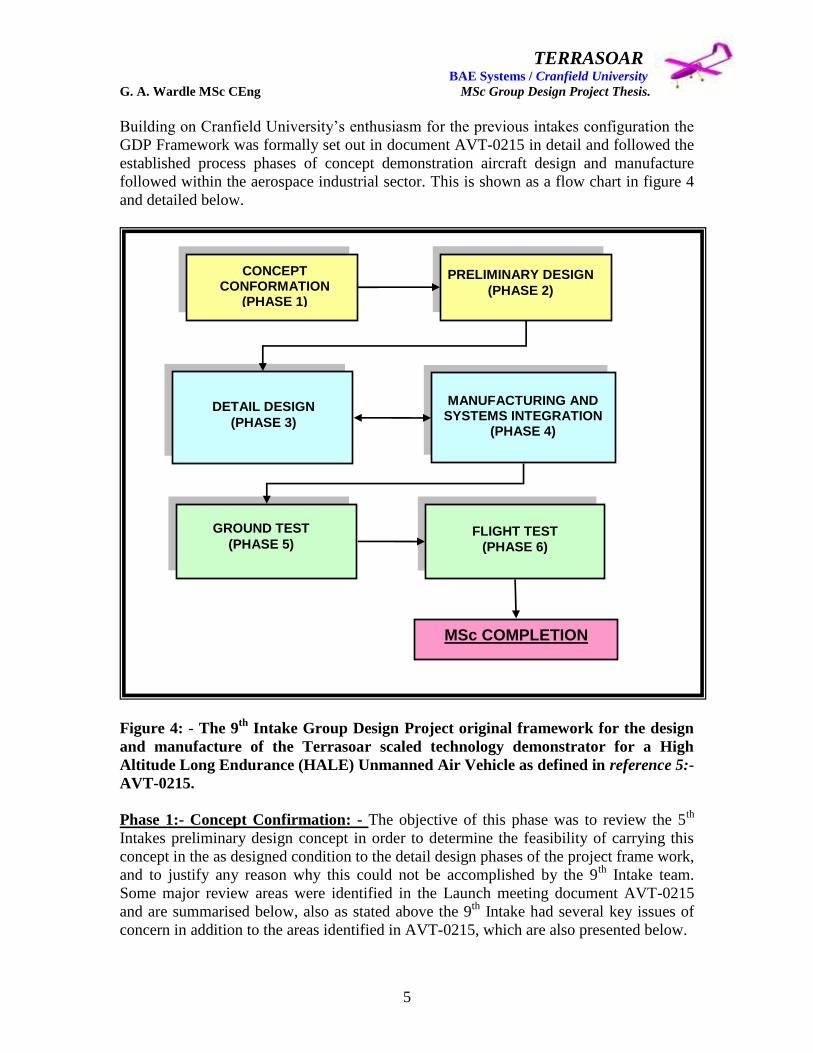
Building on Cranfield University‟s enthusiasm for the previous intakes configuration the
GDP Framework was formally set out in document AVT-0215 in detail and followed the
established process phases of concept demonstration aircraft design and manufacture
followed within the aerospace industrial sector. This is shown as a flow chart in figure 4
and detailed below.
Figure 4: - The 9th
Intake Group Design Project original framework for the design
and manufacture of the Terrasoar scaled technology demonstrator for a High
Altitude Long Endurance (HALE) Unmanned Air Vehicle as defined in reference 5:-
AVT-0215.
Phase 1:- Concept Confirmation: - The objective of this phase was to review the 5th
Intakes preliminary design concept in order to determine the feasibility of carrying this
concept in the as designed condition to the detail design phases of the project frame work,
and to justify any reason why this could not be accomplished by the 9th
Intake team.
Some major review areas were identified in the Launch meeting document AVT-0215
and are summarised below, also as stated above the 9th
Intake had several key issues of
concern in addition to the areas identified in AVT-0215, which are also presented below.
CONCEPT CONFORMATION
(PHASE 1)
PRELIMINARY DESIGN
(PHASE 2)
DETAIL DESIGN
(PHASE 3)
MANUFACTURING AND SYSTEMS INTEGRATION
(PHASE 4)
GROUND TEST
(PHASE 5) FLIGHT TEST
(PHASE 6)
MSc COMPLETION

TERRASOAR BAE Systems / Cranfield University G. A. Wardle MSc CEng MSc Group Design Project Thesis.
6
1. Methods of take off and recovery (landing) the methods proposed by the 5th
Intake were not deemed practical on terms of safety for the ground handling
personnel in either: - deploying: launching: or recovering the aircraft. Also these
proposals were seen as an over complication of the aircrafts support infrastructure
as well as the aircraft systems, and furthermore the 9th
Intake team had serious
doubts that if the aircraft could get airborne using these proposals it could be
recovered without sever structural damage, probably resulting in the loss of the
aircraft.
2. The airworthiness of the 5th
Intakes design was reviewed and found to be
unsuitable for the mission requirements which are captured in section 2 and
although the aerodynamics of original configuration may well have been suitable
for the 40,000ft altitude requirement for the 5th
Intakes GDP it represented a point
design and exactly how the original design was intended to achieve this region of
operation was unclear. This aspect of the project is detailed within reference 1:-
Mr Alan Robert Barnes thesis: - UAV Configuration Management, Certification /
Qualification & Control of Mass / C of G / Inertia.
3. Rationalisation of the 5th
Intakes airframe to ease manufacture, and reduce cost of
the vehicle. Because the lack of maturity and the unsuitability of the 5th
Intakes
design to meet the requirements set-out in section 2 this work package became a
complete redesign of the aircraft with the pre-purchased engine being and the
name being the only common features. The redesign of the wing is subject of this
thesis, with the fuselage redesign is covered in reference 6:- Mr Paul Francis
Gilligan thesis: - Fuselage Design and Integration for a High Altitude Long
Endurance Aireal Vehicle, and the empennage redesign and aircraft aerodynamics
are covered within reference 7:- the thesis of Mr James Pennington Terrasoar
aerodynamic configuration, performance and design.
4. Removal of the 5th
Intakes proposed gearbox as well as the propeller indexing
system and replacement with a toothed belt drive. All of the powerplant and
propeller issues are covered in reference 8:- Mr Damian Adams thesis: -
Terrasoar Chief Engineer, Powerplant and Manufacturing-Group Design Project.
5. Simplification of the flight control system which involved substitution of a
modern and more appropriate avionics package than the legacy „XREA‟ avionics
crate, which was the original choice for the 5th
Intakes design because of its
availability within Cranfield University being owned by the Flight Dynamics
Group. After extensive research the FCS selected for the 9th
Intakes aircraft was
the Micropilot system which was a low cost but very capable FCS and is detailed
with representative flight test data in reference 9:- Mr Robert Currie thesis: -
Development of a Cost Effective UAV Avionics and Flight Control System.
TERRASOAR BAE Systems / Cranfield University G. A. Wardle MSc CEng MSc Group Design Project Thesis.
7
6. Examination of possible payloads and the design requirements for these payloads.
The payload provision for the aircraft was set as 5kg and to be inclusive of power
and / or cooling requirements, the payload required have a separate data channel
and not to generate any electrical interference with the flight control system, and
therefore a self contained and RF / electrically isolated payload was required.
Several investigations into possible payloads were conducted by both Mr David
Baird and Mrs Rachel Cunliffe which are fully documented in reference 10:- Miss
Rachel Cunliffe thesis: - Terrasoar UAV Payload, Stability and Flutter Group
Project.
7. Possible use of new technology in areas defined by the BAE SYSTEMS –
Cranfield University namely: - Low cost high altitude payload vehicles: Novel
secondary power systems: Novel flight control systems and control surfaces: High
reliability, zero maintenance: and Novel manufacturing methods. Of these the
design of a low cost UAV and the use of novel manufacturing methods were at
the forefront of the 9th
Intakes Terrasoar aircraft design.
8. Aircraft major component sizing for the revised mission requirements in terms of
wing, empennage, and propeller sizing. As stated above the 5th
Intakes design was
sized for a mission to 40,000ft (with a different engine), and not for the 10,000ft
mission the 9th
Intake was charged with, therefore factors such as the aspect ratio
were in appropriate for the mission as was the propeller sizing, the control
surfaces were considered to be ineffective both in terms of size and location with
no redundancy, and the empennage was considered to be equally in effective.
9. Employment of either a retractable or fixed undercarriage was considered
essential after reviewing the 5th
Intakes proposed launch and recovery systems
shown in figures 5 and 6 respectively and this area is covered in reference 11:-
Mr Robert Sneddon‟s thesis (yet to be titled), as well as references 6 and 7.
10. Airworthiness clearance to JAR-VLA and the appropriateness of these
requirements, as well as the cost of certification of the aircraft to fly within
unrestricted airspace which is covered within reference 1.
11. The interface / transportation joints between the major components namely: -
centre wing to fuselage: centre wing to outboard wing: wing to empennage
booms: all of which are covered within this thesis.
12. Systems integration for the aileron actuators: rudders: elevator actuators: and
navigation lights which are covered within this thesis, and references 6 and 7.
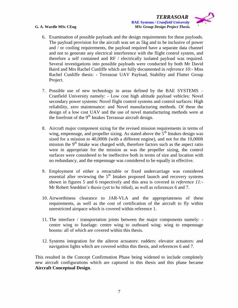
This resulted in the Concept Confirmation Phase being widened to include completely
new aircraft configurations which are captured in this thesis and this phase became
Aircraft Conceptual Design.

TERRASOAR BAE Systems / Cranfield University G. A. Wardle MSc CEng MSc Group Design Project Thesis.
8
Figure 5: - The 5th
Intake Terrasoar PDR design Vehicle launch proposal.
(Reference 3)
Figure 6:- The 5th
Intake Terrasoar PDR design Vehicle recovery proposal.
(Reference 3)

TERRASOAR BAE Systems / Cranfield University G. A. Wardle MSc CEng MSc Group Design Project Thesis.
9
Phase 2:- Preliminary design: - The objective of this phase was to produce an outline
concept design which could meet the Terrasoar UAV specification at the lowest cost
while meeting all of the functionality: flight and ground safety: reliability:
maintainability: and manufacturability targets set by the customer. To achieve this level
of maturity all major risks had to be identified and reduced to an acceptable level, but as
will be seen in later sections maturation weight gain and manufacturing costs were to
play key roles design decisions making even after the Critical Design Review this is a
situation all too common in both civil and military aircraft projects and even small
aircraft such as ours was not exempt.
From the start of the project the key decision was made to use 3D CATIA solid and
surface models rather than sets of paper drawings and lofts to communicate design intent
because these could be readily interrogated by the prime airframe contractors the 9th
Intake considered capable of producing this aircraft, and modified much easer than paper
drawings. Also 2D drawings could be readily extracted from the 3D model as and when
required. This decision has enabled the design to progress to the level of maturity
presented within this thesis which would not have been possible with manual drawings,
although because this aircraft required flight certification only licensed CATIA V4 could
be used within BAE Systems which has lead to a heavy work load on the only two
qualified design engineers within this team namely myself and Mr James Pennington, and
the one manufacturing engineer we trained to use CATIA V4 namely Mr Paul Gilligan.
The exit criteria for the preliminary design phase was the Preliminary Design Review
(PDR) at which the final Outer Mould Lines (OML) were frozen for the aircraft and the
basic airframe assembly philosophy was defined, and the majority of the major problem
areas had been resolved to a point where detail design could be undertaken and this phase
was completed on the 3rd
March 2004.
Phase 3:- Detail design: - The objective of this phase was to produce the matured detail
design, assembly methodology, systems installation models, and manufacturing models,
of a standard for release to manufacture. However although the design layout was mature
the detail stressing of the airframe was delivered late and consequently no models could
be released except for OML tooling could be released to manufacture. Although in the
unstressed condition the aircraft was considered capable of complying with the
specification and design requirements. At the Critical Design Review of the 21st April
2005 the aircraft was judged by Cranfield and BAE Systems sufficiently matured to
proceed to an additional final design for manufacturing phase when final stress data
became available on the 23rd
May 2005, although this design phase proved to be more
protracted than originally foreseen due to weight growth, materials and manufacturing
methodology changes, and stress data revisions and is only now coming to a close in
November 2005.
TERRASOAR BAE Systems / Cranfield University G. A. Wardle MSc CEng MSc Group Design Project Thesis.
10
Phase 4:- Manufacture and systems integration: - This phase is scheduled to start in
February 2006 although initial tool design is currently taking place at BAE Systems Man
Tech facility, and the manufacture of all metallic details have been approved for
manufacture with BAE Systems.
Phase 5:- Aircraft Ground Testing: - Planning for this phase has been completed and
can be reviewed in references 1, 2, 8, and 9, also the engine has been ground tested to
determine the specific fuel consumption figures for the engine to enable accurate fuel
tank sizing prior to CDR and this is covered in references 2 and 8.
Phase 6:- Aircraft Flight Testing: - Planning for this phase has been completed and is
covered in reference 1, also the Micropilot FCS has been successfully flown on several
simulated missions in a model aircraft at BAE Systems Samlesbury airfield and these
qualification flights are covered in reference 9.
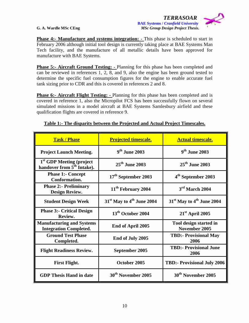
Table 1:- The disparity between the Projected and Actual Project Timescales.
Task / Phase Projected timescale. Actual timescale.
Project Launch Meeting. 9th
June 2003 9th
June 2003
1st GDP Meeting (project
handover from 5th
Intake). 25
th June 2003 25
th June 2003
Phase 1:- Concept
Conformation. 17
th September 2003 4
th September 2003
Phase 2:- Preliminary
Design Review. 11
th February 2004 3
rd March 2004
Student Design Week 31st May to 4
th June 2004 31
st May to 4
th June 2004
Phase 3:- Critical Design
Review. 13
th October 2004 21
st April 2005
Manufacturing and Systems
Integration Completed. End of April 2005
Tool design started in
November 2005
Ground Test Phase
Completed. End of July 2005
TBD:- Provisional May
2006
Flight Readiness Review. September 2005 TBD:- Provisional June
2006
First Flight. October 2005 TBD:- Provisional July 2006
GDP Thesis Hand in date 30th
November 2005 30th
November 2005

TERRASOAR BAE Systems / Cranfield University G. A. Wardle MSc CEng MSc Group Design Project Thesis.
11
From Table 1 above it can be seen that there was a marked disparity between the
projected timescales and the actual (achieved) timescales of the Terrasoar project and
they strongly diverged after the Preliminary Design review. This was due to four primary
reasons which were: -
(1) The projected time scales were based on Cranfield University‟s initial assumption that
the 5th
Intakes concept would require relatively little modification and had reached a level
of maturity close to that required for detail design to commence, this however was not a
view shared by the 9th
Intake or BAE Systems.
(2) The volume of work required to produce a design suitable for manufacture was to
great for a team of three designers working in their own time without the commitment for
hours or support of their line management, and the compelling commitments to the BAE
Systems flagship project JSF / F-35 which itself is under resourced in design and stress
disciplines with the design team on Terrasoar working a 7:00am to 7:00pm day on JSF
not much “free time” could be devoted to the detail design phase.
(3) The need to use only licensed CAD software i.e. CATIA V4 which was only available
within BAE Systems, this was paramount for aircraft certification.
(4) The late issuing of stress data due to the full-time work commitments of the 9th
Intake
stessman, and the use of novel airframe materials.
Therefore the projected phase completion dates could not be met and should be
considered as over ambitious. This concludes discussion of the statement of work as
issued in the 9th
Intake GDP Launch Presentation document AVT-0215.
1.2: - 9th
Intake Roles and Responsibilities.
After completion of Phase 1 Conceptual Design (detailed in section 3 of this thesis) as it
was re-designated after the scope of this phase was widened as described above, the 9th
Intake selected roles and responsibilities within the Terrasoar Project Team based on their
normal full – time working functional discipline e.g. design, stress, manufacturing, etc or
an area in which they would had specialist expertise outside the daily work environment
such as large scale model building and flight operations, or even an area they wished to
explore e.g. aerodynamics, or payload integration. The 9th
Intake was unusual in that for
the first time two streams of the course were run concurrently of which one was the
engineering stream and other was the manufacturing stream. This lead to a greater degree
of detailed manufacturing planning, and early process definition than in the 5th
Intake,
however the number of designers remained small i.e. two compared with previous
intakes, although one manufacturing engineer Mr Paul Gilligan undertook the major
design role as the fuselage designer and fuselage systems integrator much effort was
required on his part to learn the skills set required to use CATIA V4 and myself and Mr
James Pennington took time form our design maturations to train him fully in the design
toolset.

TERRASOAR BAE Systems / Cranfield University G. A. Wardle MSc CEng MSc Group Design Project Thesis.
12
The other manufacturing engineers who helped the design effort Mr Damian Adams who
provided detail design support in CATIA V5 to Mr James Pennington and Mr Paul
Gilligan in respect of the engine mounting frame, and Mr David Baird who supported my
wing design with conceptual aileron designs based on sizing generated by James
Pennington and Miss Rachel Cunliffe. Additional detail design support was given by Mr
Alan Barnes for empennage / boom interface and Mr Robert Currie for the avionics tray
and from Mr Vernon Hind for the full fuel tank design and the fuel system for which he
was responsible. No other members of the team offered any design support although Mr
Robert Sneddon was specifically charged with undercarriage design in addition to his
primary stress role no work in this area was forthcoming and the design of this system
was undertaken by James Pennington and Paul Gilligan.
Figure 7 shows the 9th
Intake Organisational structure as of November 2005, although the
original intake was as follows:-
Paul Gilligan James Pennington Bob Currie
Damian Adams Alan Barnes Dave Baird
Rob Sneddon Vernon Hind Craig Carr
Jon Baggaley Rachael Cunliffe Rob Cunliffe
Emma Bradley.
Where Craig Carr had the role of airworthiness certification and materials selection but
left the course in March 2004: and John Baggaley had the role of control surface and
structures design support but left the course in January 2005 and the loss of both of these
talented individuals was a blow to the team. Although Craig Carr has been a great help to
the team in his new as a senior engineering specialist within the Man Tech organisation
as the design of Terrasoar has neared manufacturing design readiness. The developments
of organisational structures and inter - team dynamics is covered within reference 8 and
will not be covered within this thesis, and in my view the team have done the best they
can within the timeframe available.
The design challenges of the Terrasoar were undertaken by the Airframe Design Team,
which I was selected to lead as the Airframe Lead shown in figure 7, with responsibilities
for: - co - ordination of all of the airframe design and systems integration activities,
project planning and scheduling, and sole design responsibility for the wing, and wing
flight control surface and systems integration, as well as the wing mounted navigation
lights.

TERRASOAR BAE Systems / Cranfield University G. A. Wardle MSc CEng MSc Group Design Project Thesis.
13
Fig
ure
7:-
9th
IN
TA
KE
TE
RR
AS
OA
R P
RO
JE
CT
TE
AM
OR
GA
NIS
AT
ION
CH
AR
T.
TERRASOAR BAE Systems / Cranfield University G. A. Wardle MSc CEng MSc Group Design Project Thesis.
14
As Airframe Lead my priorities were to provide oversight of the design activities and out
brief these to the Chief Engineer, and the rest of the Terrasoar project team for their bye
in and discussion, identification of design information requirements from structures,
aerodynamics, systems, propulsion and manufacturing. Provide project planning, and
identification of design milestones, design training, and design procedures
documentation, for configuration control.
As Wing Chief Designer my priorities were to develop a wing concept which satisfies the
following requirements: - transportation breakdown into sections, load transfer through a
multi section structure, systems integration and access, mate joint philosophy, and
manufacturing philosophy. To this end I have focused my seven years of aircraft airframe
design experience to produce an engineering solution which meets the Terrasoar design
requirements. Additionally I also developed a wing test programme based on my four
years as a Senior Structural Test Engineer at the BAE Systems Structural Test Facility
Brough.
My first task as Airframe lead was to establish a design manual for the Terrasoar aircraft
so that all design activities were conducted to the same standard and design intent could
be understood by manufacturing and assembly personnel as well as the customer and
certification and airworthiness authorities. Because this aircraft had to meet real - world
airworthiness and certification requirements, the basis used for the design manual was the
BAE Systems design standards. This manual is covered in the next section to demonstrate
the level of control afforded to this design.
1.3:- Terrasoar Design methodology (Design Manual).
1. Introduction.
This Design Manual is intended only for use on the Terrasoar project and serves as
the reference for designers to the BAE Systems Technical Standards Manuals, and
CATIA design procedures within BAE Systems produced and maintained by DPA,
and accessed through the BAE Systems Intranet /Airframe Engineering / Design /
User Guides / Approved Methods.
This Design Manual states how the design schemes will be produced and co-
ordinated in a systematic methodology in accordance with Technical Standards
Manual 01.04.27. All of the methods covered within satisfy the requirements of ISO
9001, JAR, Defence Standards 00-970 and 05-123, for the production and
management of Design Schemes.
The procedures laid out and referenced in this manual will apply to all significant
design tasks (except for Repair Schemes) and its application has been agreed by the
Airframe Design Lead and the Terrasoar IPT Chief Engineer.

TERRASOAR BAE Systems / Cranfield University G. A. Wardle MSc CEng MSc Group Design Project Thesis.
15
2. Design scheme control philosophy.
The Terrasoar Airframe is broken down into the following major airframe
components which are designed and controlled by the processes and procedures
covered by this manual. These major airframe components are listed below:-
Fuselage: - This includes the internal structure; skins; internal and external
systems integration; powerplant integration; fuel system integration, and
recovery system integration.
Wing: - This includes the internal structure; skins; flight control surface design;
and systems integration.
Tail Booms and Empennage: - This includes boom and empennage structure;
skins; control surface design; and systems integration.
These major airframe components will use a common axis system known as the
AIRCRAFT AXIS all component axes will be defined relative to this aircraft
axis and no component designer will disregard this rule.
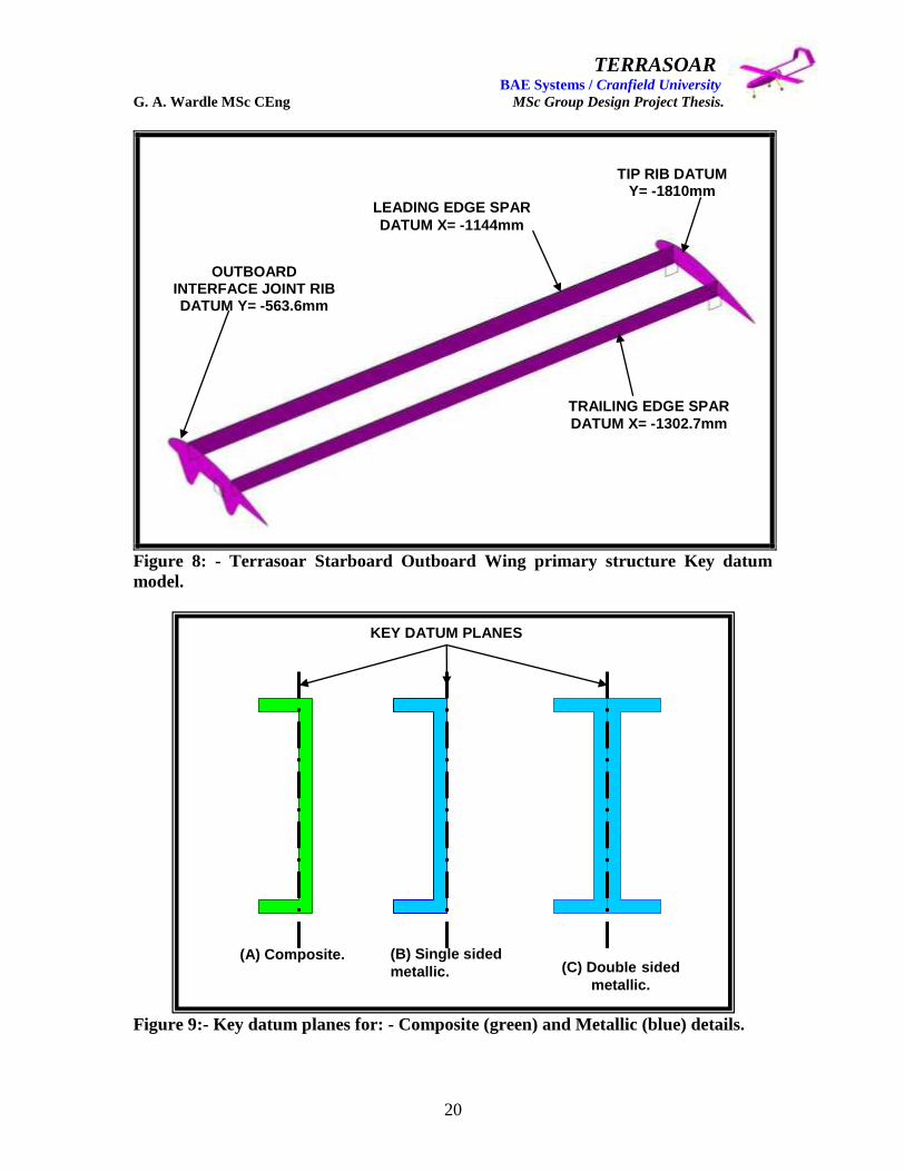
Key Datum Models: - Will record the location of all structural elements of each
component and will be defined at component level and integrated with the
Aircraft Axis, (an example of the starboard wing substructure Key Datum
Model is shown in figure 8 and datum planes in figure 9). The primary function
of these models is to enable analysis of the structure of the aircraft and
determine the load paths, and interfaces between components.
Assembly Model: - This is a master model into which the component models are
located. This model demonstrates the maturity and integrity of the aircraft
structural layout; systems integration; fastener layout; and skins design. This
gives a timely indication of fowling / clash detection. Each component would in
an aircraft of high complexity and substance have an individual assembly model
but this is not deemed necessary for a modest UAV.
3. Design scheming.
All design schemes will be formally numbered in accordance with the Terrasoar
project rules with numbers issued by the Configuration Control Authority,
reference 1, using the relevant title block.
Schemes status will be identified adjacent to the title block prior to release outside the
Airframe Team responsible for the scheme‟s creation.
TERRASOAR BAE Systems / Cranfield University G. A. Wardle MSc CEng MSc Group Design Project Thesis.
16
An Item Release Schedule (IRS) will be prepared and issued, which will detail:-
The scheme numbers
Brief description of content
A, B and C Status dates in accordance with the Design Programmes
Management Procedures TSM 01.09.15.
There are three levels of scheming:-
A Status: - Design concept / feasibility.
B Status: - Definition of basic structure / system and other specialist
requirements (Preliminary Design Review).
C Status: - Comprehensively engineered and sized drawing depicting the
„frozen‟ agreed configuration standard for the product (Critical Design
Review). The C status scheme will contain the following:
1. Pictorial views or solid models of the assembly with detail views and balloon
references including the components with sufficient dimensional data to
enable engineering drawing to commence and stress weights and production
engineering requirements to be satisfied.
2. Jigging hole positions.
3. Control dimensions, datum‟s and ICY requirements identified.
4. Special notes / reminders.
5. A Bill of Materials (standard parts / equipment) material specifications and
used on drawing numbers.
6. A „Circulation Box‟ with names of functional representatives working on the
changed area.
7. Change effect statement in the title block (according to project needs).
8. The detail parts which will NOT require a Structures Team signature on the
manufacturing drawings prior to production will be identified using the flag
note system relevant to the project. This will be indicated on the part number
on the face of the drawing and in the Bill of Materials. The note itself WILL
reference the Design Review Meeting Minutes at which endorsement of this
status was given.

TERRASOAR BAE Systems / Cranfield University G. A. Wardle MSc CEng MSc Group Design Project Thesis.
17
Detail manufacturing drawings indicated thus will be identical to the „C‟ status scheme
with NO DEVIATION allowed.
All detail manufacturing drawings created will reference the „C‟ status scheme.
Frozen „C‟ status schemes once agreed cannot be changed without recourse to the formal
change control procedure.
The „C‟ status scheme forms the basis for the creation of Engineering / Manufacture
drawings.
It should be noted that the „C‟ status scheme can be used by Departments downstream of
the Airframe Team to carry out advanced tooling, preliminary planning activities etc., in
advance of the receipt of manufacturing drawings. It is NOT an authority to proceed
with manufacture. Any advance manufacturing activity from „C‟ status schemes
will be strictly „at risk‟ of scrap.
Note 1: Guidelines on scheme content to be used in the preparation of each status of
scheme are given in APPENDIX 1 of TSM 01.04.27 (Volume 01 – General Design
Procedures).
Note 2: At B Status consideration may be given to advance ordering of material, long
lead items and major components in conjunction with Production Engineering.
Note 3: At C Status, advance ordering requirements may be specified in accordance with
TSM 01.09.08 (Engineering Advance Material Release) project rules, and Design Visual
Examination (DVE) in accordance with TSM 01.09.16.
The use of A and B status schemes within this project will give a design history and
allow assessment of the level of maturity each component has reached over the span of
the design activities. It is mandatory that the final scheme status is always C for all
project design tasks.
Initial issue and each raise of issue of a scheme will be by sequential numbering, as per
normal practice. However, any changes of status requires a new scheme number and a
raise of issue of the previous status scheme to record cross – reference to new scheme
number. Each issue will be controlled by the relevant site documentation which will act
as the signature collection document for the scheme in accordance with normal Drawing
approval procedures. The equivalent site documentation is: -

TERRASOAR BAE Systems / Cranfield University G. A. Wardle MSc CEng MSc Group Design Project Thesis.
18
Design Change Note: (DCN) – Warton / Samlesbury.
Design Department Instruction: (DDI) – Brough.
The DCN / DDI will contain a written statement of changes to be made to the scheme
from the previous issue. DCN / DDI numbers will be taken from the project register /
scheme control sheet (Sheet 1 normally).
Circulation at the initial issue must be specified above the scheme title block. All
subsequent issues will receive the same circulation. Changes in circulation are permitted
providing they are recorded in the scheme.
In considering the circulation of schemes, selection should be from the following:
Technical – Relevant departments affected:
Cost Engineering:
Process Engineering:
Manufacturing, including Jig & Tool Design and NC Programming:
Other BAE Systems sites (checkers):
Subcontractors when applicable.
To avoid delay or non – availability of schemes whilst being passed through the normal
issuing system, printing and distribution will be permitted ONLY WITH: -
PRELIMINARY DRAFT clearly written on the drawing boarder or tagged to a solid
model. Final schemes and all DCN / DDI‟s issued must be filed in the Terrasoar Design /
Model Store and stored electronically by Configuration Control PDM system, until
project hand over in 2006.
All Design / Stress programmes and Drawing release schedules for significant design
tasks will carry dates for A, B, and C status schemes as appropriate.
The Bill of Materials will be of the Manual type based on Figure 10, but will initially be
based on an excel spreadsheet owned by configuration control this will then be
transposed onto the PDM system and will use the same Eurofighter format as on the pre –
printed detail sheets.
The following Technical Standards Manuals will be followed for the production all
design schemes and engineering drawings for the Terrasoar Project: -
TSM 01 General Design Procedures.
TSM 08 CATIA Procedures.
TSM 12 Lofting Procedures.
TSM 13 Structures Design Procedures.

TERRASOAR BAE Systems / Cranfield University G. A. Wardle MSc CEng MSc Group Design Project Thesis.
19
TSM 14 Mechanical Systems Design Procedures.
TSM 15 Electrical Bonding / Lightning Strike / EMP Design Procedures.
TSM 16 Electrical Installation Design Procedures.
TSM 19 Design Quality Procedures.
TSM 42 Metallic Material Processing Standards.
The following BAE Systems CATIA user guides will be used for all Terrasoar CATIA
design activities: -
BAE – WDO – GDE – GEN – DPA – 150832 General Solid Modelling.
BAE – WDO – GDE – GEN – DPA – 150827 Modelling Machined Parts.
BAE – WDO – GDE – GEN – DPA – 150826 Modelling Sheet Metal Parts.
BAE – WDO – GDE – GEN – DPA – 150829 Modelling Carbon Fibre Composite
Parts.
BAE – WDO – GDE – GEN – DPA – 150885 Interference Analyses.
BAE – WDO – GDE – GEN – DPA – 150896 Drawing Productions.
BAE – WDO – GDE – GEN – DPA – 150833 CATIA Database Assemblies
Scheming.
4 Scheme Approvals.
All schemes will be fully checked before final issue, and final approval of a scheme for
issue will be an acknowledgment that due consideration has been given to: -
The design is fit for purpose.
All reasonable design paths have been explored.
All relevant factors have been considered.
The design can be cost effectively produced, inspected, tested, installed, operated
and maintained in a satisfactory manner.
There is adequate documentation to support the design.
Target masses have been achieved („C‟ Status).
TERRASOAR BAE Systems / Cranfield University G. A. Wardle MSc CEng MSc Group Design Project Thesis.
20
Figure 8: - Terrasoar Starboard Outboard Wing primary structure Key datum
model.
Figure 9:- Key datum planes for: - Composite (green) and Metallic (blue) details.
(A) Composite. (B) Single sided
metallic. (C) Double sided
metallic.
LEADING EDGE SPAR
DATUM X= -1144mm
TRAILING EDGE SPAR
DATUM X= -1302.7mm
OUTBOARD INTERFACE JOINT RIB DATUM Y= -563.6mm
TIP RIB DATUM Y= -1810mm
KEY DATUM PLANES

TERRASOAR BAE Systems / Cranfield University G. A. Wardle MSc CEng MSc Group Design Project Thesis.
21
Figure 10:- Standard Bill of Materials. TSM 01.04.27.(Note after to prevent
confusion with other projects on the Eurofighter PDM system the Terrasoar Project
aircraft B o M was compiled as an excel spreadsheet and maintained by design and
controlled by configuration management).

TERRASOAR BAE Systems / Cranfield University G. A. Wardle MSc CEng MSc Group Design Project Thesis.
22
Note: Schemes will only be submitted to functional specialists for technical approval
after they have been checked by the Airframe Team they will be reviewed by the
customer and signed off because for this project only Cranfield University is the design
authority. Scheme and models that do not carry a checking signature or are not supported
by the sign off document must be returned to design.
Functional specialists will not carry out a check on drawing quality. If spotted however,
any errors are to be notified to the Airframe Team for correction.
2: - Requirements capture.
The objective of the Terrasoar project was to produce a single engine pusher propeller
high wing monoplane uninhabited air vehicle (UAV), which is capable of flying at
10,000ft for a duration of 5 hours, with a payload of 5kg‟s in unrestricted airspace.
The GTOW of the aircraft was not to exceed 40kg‟s which impacted on both the
selection of a structural design philosophy for the aircraft, the materials to be used, and
the manufacturing processes employed to produce the airframe components.
The requirement for the airframe to be dismantled for transportation to and from the
flight test location and rapidly reassembled for the flight trials, with subsequent rapid
brake down for transport after trials, and the dimensions of the doors, with the need to
ensure adequate clearance for extraction of the aircraft from the Ford transit transport
vehicle dictated the size of major airframe components. Therefore types of structural
mate joint for the airframe components needed to be robust and easy to assemble.
The need to embody and integrate multiplex redundant systems which could be accessed
prior to flight, made provision of quick release access panels which could then be sealed
for flight a priority and posed significant challenges for the wing, fuselage design, and
empennage design and for the wing this is covered within this thesis.
The key parameters of the 5th
Intakes concept were presented within AVT-0215 and
formed the starting point for the 9th
Intakes design studies for the revised Terrasoar, and a
brief specification of this vehicle (which resulted from the 5th
intake work) is as follows: -
MTOW 40 Kg
Maximum Altitude 10000ft
Payload Capacity 5 Kg
Wing Span 5.5m
Wing Area 1.21m2
Aspect Ratio 25
Outer Wing Dihedral 5 deg

TERRASOAR BAE Systems / Cranfield University G. A. Wardle MSc CEng MSc Group Design Project Thesis.
23
Mission Duration Approx 5 hours with 1 hour loiter at max altitude
Powerplant MOKI 215cc 4 stroke 5 cylinder Radial engine
(13.5hp at 4300rpm) www.moki.co.uk
2.1: - Aircraft specification document divergence.
The Aircraft specification document was incorporated within AVT-0215 and was very
prescriptive with a view to promoting the 5th
Intakes design solution this was later
modified to reflect the research findings of the 9th
Intake and their impact on the
Terrasoar aircraft, the initial airframe description and the resultant changes are given
below.
(a) Payload requirements: -
The aircraft was to be capable of carrying a maximum payload of up to 5 Kg. Where this
mass was to include all provision for power and / or cooling of the payload.
In addition, the aircraft nose was to be transparent to the payload sensor frequency
enabling for forward, up, down, and sideways field of regard for the payload. In addition,
provision of a continuous airflow through the payload bay during the flight of the aircraft
for environmental, for sampling payloads, must considered.
The MicroSAR, which is a low cost Synthetic Aperture Radar, was considered as a
possible payload for the Terrasoar aircraft, and was being used for land and sea detailed
observation. Market sectors include agriculture, forestry, geology, and maritime. Details
of this sensor were available at the web sites given below: -
www.imicrosensors.com www.astrium-space.com
The Cranfield contact for MicroSAR was Dr. Steve Hobbs, Astronautics and Space
Engineering (telephone 01234-750111 ext 5121 e-mail [email protected] ).
BAE SYSTEMS had a requirement for a low cost vehicle for airborne testing of one of a
radar system which is covered within reference 10.
A further payload considered was the Hyper Spectral Camera, which had applications for
monitoring water quality and changes to the coastline and estuaries. One problem of any
such camera is that it may have to be mounted on a small stabilised platform to remove
angular movements of the aircraft in flight. This is a trade off with the Flight Control
System.

TERRASOAR BAE Systems / Cranfield University G. A. Wardle MSc CEng MSc Group Design Project Thesis.
24
Ultimately to reduce the manufacturing cost of the aircraft the current which is
considered as a concept demonstrator and manufacturing process learning tool, the nose
covering the payload bay was made from hand layed carbon fibre cloth and as such is
opaque to all of the above payloads, and is shown in figure 11, and the design and
manufacture of this article is covered within references 6 and 7.
Figure 11: - Terrasoar nosecone / payload bay cover manufactured by Man Tech
BAE Systems Samlesbury. (Source: - Man Tech BAE Systems).
The Terrasoar in its current form will now carry ballast representative of an inclusive
payload mass of 5kg.
(b) Airframe Construction: -
The airframe mass and physical size was kept to that required for the missions outlined
within this thesis and covered in depth within reference 1, although maturation weight
gain due to conservative safety factors due to the novel nature of the construction
materials selected for the airframe have been a consistent challenge to achieving the
performance and payload capability required.

TERRASOAR BAE Systems / Cranfield University G. A. Wardle MSc CEng MSc Group Design Project Thesis.
25
Careful consideration was given in the airframe design to ease of: -
Transportation:
Assembly and Dis-assembly:
Manhandling.
The above areas are covered in sections 4 and 5 of this thesis.
Materials used in the construction are limited only by the need to avoid those which are
dangerous to individuals and the environment.
It was expected that use would be made of composite materials to achieve the mass and
stiffness targets of the airframe, and indeed extensive use of low temperature (800 C to
1000 C) curing glass pre-preg cloth was intended for the wing and empennage with resin
infusion intended for the fuselage of this aircraft to reduce manufacturing costs and
provide manufacturing process “learning” within BAE Systems.
Economic construction methods which minimised costs of airframe manufacture were
used in conjunction with the technology development requirements within BAE Systems
to develop methodologies to build small low cost UAV‟s, and this is covered within
section 7 of this thesis in relation to the wing and in reference 6 with respect to the
fuselage. A suitable manufacturer was selected by selecting BAE Systems Man Tech and
the reasons for this are covered within references 8, 6, and 1, Man Tech is consistent with
the quality requirements for the route to certification.
The sensitivity of any payload sensor requirements to the fuselage material surrounding it
was investigated, but for the reasons given above the payload has been omitted from this
configuration.
(c) Propulsion: -
Intake 5 purchased a MOKI 215cc 4 stroke 5 cylinder radial engine. This engine was to
be utilised for the 9th
Intakes GDP. Some limited engine with propeller testing was
conducted by Intake 5 at Woodford.
This testing was evaluated and the engine performance was confirmed by additional
testing which was conducted at ground level (taken as sea level) ambient conditions using
a ground test rig designed and constructed specifically for Terrasoar testing, and is
covered within reference 8.
The engine was integrated into the aft fuselage and this is covered within references 6
and 8. Studies were instigated to determine if the engine gearbox could be removed and
replaced with a simple toothed belt drive, in order to remove cost and reliability
associated with the gearbox and these are covered within reference 8.

TERRASOAR BAE Systems / Cranfield University G. A. Wardle MSc CEng MSc Group Design Project Thesis.
26
(d) Performance: -
1) Height and Altitude:-
The maximum normal operating altitude will be 10000ft. The MOKI engine performance
needs to be confirmed at this altitude. The funds provided for this project of £100,000
were just sufficient to cover the aircraft manufacture, materials, systems, and
qualification testing, as well as Category B flight clearance to 400ft, full certification to
fly the aircraft above 400ft would have required additional in the order of £50,000 and
after consultation with the customer additional funding was ruled out. Therefore this
requirement was deferred and removed form the 9th
Intake, thus there was no need to test
the engine at altitude for the flight test program currently selected for this stage of the
Terrasoar project, which are outlined below in section 2.2, and covered in detail in
references 1 and 8.
2) Endurance:-
The vehicle was to be capable of a 1 hour loiter at the maximum normal operating
altitude. The maximum total mission time will be 5 hours. This requirement was also
changed to reflect the missions outlined in section 2.2 and detailed in references 1 and 8.
3) Velocity:-
No limitation on vehicle velocity was set. Consideration however must be given to the
ability to maintain position in typical wind speeds at altitude. The aircraft is deemed
capable of meeting the stability and speed requirements of the missions outlined in
section 2.2, for further information the reader is referred to references 1 and 8.
4) Environmental Conditions:-
Initially defined performance characteristics which were to be available under ISA
conditions up to 10000ft were modified to take account of the revised mission
requirement and reduce the complexity an hence cost of the aircraft systems: -
Although it should be possible to operate the aircraft under temperature variations from a
minimum operating temperature of -15 0C to a maximum operating temperature of +115
0C, (for manufacture) no funds were available to qualify the adhesive joints which
constitute the majority of the airframes interfaces within this temperature range especially
the operating minima.
Operation in icing conditions was not required, but consideration was to be given to the
use of de-icing fluids on the vehicle. The compatibility of the materials and adhesives
with de-icing fluids was not tested but should constitute a further work package on a
Terrasoar envelope expansion program should one be considered by the customer.

TERRASOAR BAE Systems / Cranfield University G. A. Wardle MSc CEng MSc Group Design Project Thesis.
27
Provision was also to be provided to permit possible operation of the aircraft in moderate
rainfall conditions. All joints and gaps are to be sealed using glass composite closure
plates for the control surfaces and end of part, as well as PRC sealant, and aero - tape
(used on gliders and large model aircraft, which will enable the aircraft to operate in
conditions of light to moderate rainfall. However the FCS was not tested to establish if
loss of signal would occur in theses conditions and the reader is referred to reference 9
for further details on this aspect of the FCS operational test and verification.
The system was also to have been able to operate, including launch and recovery in
surface wind speeds of up to 10m/s, and structurally the airframe was capable of
operating within these parameters however the reader is directed to references 1, 8, and 9
for clarification of the FCS, and engine capabilities under these conditions.
(e) Systems and operational aspects: -
The following requirements were read in conjunction with CAP722 „CAA UAV
Operations in UK Airspace‟ (ref 2).
1) Launch and Recovery:-
Launch and Recovery was to be accomplished by whatever means are deemed
appropriate. Operation, however, must be possible from areas such as small airfields. If
any physical facilities are required, then these must be defined. As stated above the 9th
Intake rejected the proposals of intake 5 and a fixed tricycle undercarriage was used with
nose wheel steering and brakes, this is covered within references 6 and 7.
Consideration was to be given to propeller clearance during launch and recovery. This
was a risk which when considering using the Intake 5 configuration. Because of the lower
altitude requirements of the initial specification the propeller was resized accordingly,
and an undercarriage sized to meet the propeller clearance requirements during aircraft
rotation was designed for Terrasoar. The sizing of the propeller is covered in references 7
and 8.
2) Range:-
The air vehicle was to be able to operate up to at least 20Km from the Ground Control
Station (GCS). Category B clearance was given to line of site range to ensure adequate
manual revision this is covered within reference 1. An overview of the missions slated for
the Terrasoar aircraft is given in section 2.2 of this thesis and are covered in detail in
reference 1.

TERRASOAR BAE Systems / Cranfield University G. A. Wardle MSc CEng MSc Group Design Project Thesis.
28
4) Vehicle Avionics Package:-
The original 5th
Intake Terrasoar was designed to use the „XRAE‟ avionics crate, which
was shared with Eclipse and Total Eclipse, neither of which has ever flown or are likely
so to do, hence because of its availability and capability it was proposed for the Terrasoar
small UAV. Eclipse and Total Eclipse were both unstable aircraft configurations.
However because Terrasoar is a stable aircraft, the question was raised about whether the
XRAE crate and its Flight Control System (FCS) were necessary. After inspection of the
XRAE crate by the 9th
Intakes FCS expert Mr Robert Currie it was suggested that the best
location for this device was a Science Museum exhibit, and after much research and cost /
capability trades the Micropilot FCS system from Canada was selected and this system is
covered in detail within reference 9, and its integration with the airframe is covered in
reference 6.
The Cranfield contact for FCS is Mike Cook, Flight Dynamics Group (telephone 01234-
750111 ext 5337 or e-mail [email protected] ).
The avionics requirements for UAV flight in shared airspace were also to be investigated,
and the cost of achieving this needed to be determined. Two possible choices were
proposed by the Cranfield University which were as follows: -
(a) Could the Terrasoar be given the capability to fly in shared airspace?
(b) Could the Terrasoar be limited to flying over a range within the confines of controlled
airspace?
The Barrow-in-Furness range in Cumbria was originally proposed by the customer but
this proved to be too expensive and the range selected for all planned Terrasoar flights
was Cambeltown Airport (previously known as Machrihanish Airport) in Argyll,
Scotland under the operational umbrella or BAE Systems Regional Aircraft Prestwick,
this is covered in detail in references 1 and 8.
(f) Design requirements: -
The route to certification was to be established by following the guidelines of ref 1
„Aircraft Airworthiness Certification Standards for Civil UAV‟s issued by the CAA.
Terrasoar was required to meet the guidelines in ref 1 and the airworthiness requirements.
These were to be either: - Microlight aircraft (section S), JAR VLA (very light aircraft) or
JAR VLA (very light aircraft) or JAR 23. In the event the JAR VLA (very light aircraft)
requirements were selected as the route to certification and the implementations of these
requirements are covered in references 1 and 8.

TERRASOAR BAE Systems / Cranfield University G. A. Wardle MSc CEng MSc Group Design Project Thesis.
29
2.2. Revisions mission requirement specification.
The mission requirements for the Terrasoar aircraft: - airframe, flight control system,
avionics, propulsion, and fuel systems clearance (i.e. the complete Terrasoar platform as
an integrated system, for handover to the customers Cranfield University and BAE
Systems had changed from a single flight to 10,000ft which was determined to be
unrealistic within the Terrasoar budget and timescales, to four modest missions as
described below, to be flown from Cambeltown Airport (previously known as
Machrihanish Airport) in Argyll, Scotland.
The selection of Cambeltown Airport was due to its proximity to the sea permitting
emergency diversion, and the airports current low operational usage. Flight Testing was
to be performed in Uncontrolled/Sanitised Airspace and would strictly adhere to an
issued Flight Plan sanctioned and Approved by BAE Systems – Regional Aircraft,
Prestwick, who were the flight certification authority for the Terrasoar aircraft.
All Take-Off and Landings was to be performed by the Mission Commander; who would
be a certified pilot with a valid Private Pilots Licence (PPL).
Figure 12: - Cambeltown Airport illustrating its layout and proximity to the sea.

TERRASOAR BAE Systems / Cranfield University G. A. Wardle MSc CEng MSc Group Design Project Thesis.
30
In order to minimise any damage to personnel, buildings, vehicles etc all flight plans
devised by Mr Alan Barnes and detailed in reference 1 were chosen to be where possible
predominately over the sea. However this would not be possible in the early flight test
stages because the range of the radio control signal was limited to 400 metres.
The four flight test plans selected for each were as follows and are presented in overview
here: -
S1 Initial Airworthiness evaluation – Pilot In Control PIC / 400 meter radius /100
metre altitude:
S2 FCS Evaluation – As S1 (Micropilot FCS) autopilot engaged:
S3 Out of Radio Control Range evaluation – 1 kilometre range over sea/700metre
altitude:
S4 Endurance evaluation – 3km range over sea/700 metre altitude/1Hour endurance.
Mission S1: - Initial Airworthiness evaluation.
Certification S1 was to be the initial flight of Terrasoar after acceptable pre-flight ground
testing including fast Taxi-runs. S1 would demonstrate a preliminary level of aircraft
flight capability by performing a takeoff, single circuit of the airfield at an altitude of 100
metres. Followed by controlled approach and landing. This mission was to be performed
under full Pilot In Control (PIC) mode. The level of Documentation identified as
Documentation S1 in reference 1, was devised to satisfy the signatory that the air vehicle
had been designed to achieve a safe and controlled flight. Successful achievement of
Certification S1 would allow progression to the next level of flight testing and would be
part of the formal aircraft Certification and Qualification documentation supplied to the
customers.
The flight plan for the S1 mission identified the proposed flight parameters including the
intended altitude and flight speeds.
Conditions: - Clear sky to XXX metres: high cloud base: no rain.
Winds: - of less than XX m/s (near still air conditions) measured wind speed at sea level.
Fuel: - XX Litres (With Ballast Fitted XX grams).
Takeoff Direction: - into wind.

TERRASOAR BAE Systems / Cranfield University G. A. Wardle MSc CEng MSc Group Design Project Thesis.
31
Figure 13: - Micropilot representation of the S1 mission flight plan. (Source: -
Reference 12: - Document Number: - T-CONFIGM-0009-Iss DRAFT (19/09/05)).
Table 2: - Mission S1 Test documentation. (Reference 12)
AVT-0215-ISS 2 Customer Specification 2
DBS-TT-0001 Design Build Standard 1
DS-TT-0001 Design Standard 1
T-CERT-0001 A/C Flight Certificate (C of AW) Statement for S1/S2 DRAFT
T-CERT-0003 A/C Level SQS 0
T-CERT-0004 Equipment Prelim Hazard Analysis 0
T-CERT-0006 Fuel PSQS Statement for S1/S2 DRAFT
T-CERT-0007 Powergen PSQS Statement for S1/S2 DRAFT
T-CERT-0009 FCS PSQS Statement for S1/S2 DRAFT
T-CERT-0010 NWS/Braking PSQS Statement for S1/S5 DRAFT
T-CERT-0010 Risk Register 1
T-COMPM-DOC Compliance Matrix 1
T-CONFIGM-0004 Terrasoar Flight Manual DRAFT
T-CONFIGM-0008 Change Control Procedure 1
T-CONFIGM-0019 Terrasoar Flight Clearance DRAFT
T-DESIGN-TS-0006 TERRASOAR AIRFRAME STRUCTURE SIGN WING 1
T-DESIGN-TS-0007 TERRASOAR AIRFRAME STRUCTURE SIGN FUSELAGE 1
T-DESIGN-TS-0008 TERRASOAR AIRFRAME STRUCTURE SIGN EMPENNAGE 1
T-DESIGN-TS-0009 U/C Design Sign-off 0
T-DESIGN-TS-0010 Design Statement for S1/S2 0
T-DESIGN-TS-0011 Stress Statement S1/S2 DRAFT
T-EDR-AVS/FCS-C FCS EDR Compliance 0
T-EDR-FUEL-C Fuel System EDR Compliance 0
T-EDR-PAYLOAD-C Payload EDR Compliance 0
T-EDR-POWERGEN-C Power Generation EDR Compliance 0
T-EDR-POWERPLANT-C Powerplant EDR Compliance 0
T-PERM-PAR-0010 Performance Statement for S1/S2 DRAFT
T-SYST-DOC-0002 System Safety Programme Plan DRAFT
T-SYST-DOC-0003 Flight Limitations 1
T-TEST-0002 Flight Testing 1
T-TEST-0005 Test Statement for S1/S2 DRAFT

TERRASOAR BAE Systems / Cranfield University G. A. Wardle MSc CEng MSc Group Design Project Thesis.
32
Mission S2: - FCS Evaluation.
Certification S2 was to be the second flight of Terrasoar after successful completion of
S1 testing. The S1 mission having demonstrated the preliminary aircraft handling in
flight by performing: - a takeoff: a circuit of the airfield at 100metres altitude: and a
controlled approach and landing. The S2 mission was to consist of a circuit of the airfield
at 100 metres altitude performed using the Micropilot FCS and PIC used only for Takeoff
and Landing. The level of Documentation identified in Documentation S2 would satisfy
the signatory that the air vehicle had been designed to achieve a safe and controlled flight
and will provide confidence testing for the FCS system within a safe window for manual
override. Successful completion of Certification S2 would allow progress to the next
level of flight testing and would be part of the aircraft Certification and Qualification
documentation.
The flight plan for the S2 mission identified the proposed flight parameters including the
intended altitude and flight speeds.
Conditions: - Clear sky to XXX metres: high cloud base: no rain.
Winds: - of less than XX m/s (near still air conditions) measured wind speed at sea level.
Fuel: - XX Litres (With Ballast Fitted XX grams).
Takeoff Direction: - into wind.
Figure 14: - Micropilot representation of the S2 mission flight plan. (Source: -
Reference 12: - Document Number: - T-CONFIGM-0009-Iss DRAFT (19/09/05)).

TERRASOAR BAE Systems / Cranfield University G. A. Wardle MSc CEng MSc Group Design Project Thesis.
33
Table 3: - Mission S2 Test documentation. (Reference 12)
AVT-0215-ISS 2 Customer Specification 2
DBS-TT-0001 Design Build Standard 1
DS-TT-0001 Design Standard 1
T-CERT-0001 A/C Flight Certificate (C of AW) Statement for S1/S2 DRAFT
T-CERT-0003 A/C Level SQS 0
T-CERT-0004 Equipment Prelim Hazard Analysis 0
T-CERT-0006 Fuel PSQS Statement for S1/S2 DRAFT
T-CERT-0007 Powergen PSQS Statement for S1/S2 DRAFT
T-CERT-0009 FCS PSQS Statement for S1/S2 DRAFT
T-CERT-0010 NWS/Braking PSQS Statement for S1/S5 DRAFT
T-CERT-0010 Risk Register 1
T-COMPM-DOC Compliance Matrix 1
T-CONFIGM-0004 Terrasoar Flight Manual DRAFT
T-CONFIGM-0008 Change Control Procedure 1
T-CONFIGM-0019 Terrasoar Flight Clearance DRAFT
T-DESIGN-TS-0006 TERRASOAR AIRFRAME STRUCTURE SIGN WING 1
T-DESIGN-TS-0007 TERRASOAR AIRFRAME STRUCTURE SIGN FUSELAGE 1
T-DESIGN-TS-0008 TERRASOAR AIRFRAME STRUCTURE SIGN EMPENNAGE 1
T-DESIGN-TS-0009 U/C Design Sign-off 0
T-DESIGN-TS-0010 Design Statement for S1/S2 0
T-DESIGN-TS-0011 Stress Statement S1/S2 DRAFT
T-EDR-AVS/FCS-C FCS EDR Compliance 0
T-EDR-FUEL-C Fuel System EDR Compliance 0
T-EDR-PAYLOAD-C Payload EDR Compliance 0
T-EDR-POWERGEN-C Power Generation EDR Compliance 0
T-EDR-POWERPLANT-C Powerplant EDR Compliance 0
T-PERM-PAR-0010 Performance Statement for S1/S2 DRAFT
T-SYST-DOC-0002 System Safety Programme Plan DRAFT
T-SYST-DOC-0003 Flight Limitations 1
T-TEST-0002 Flight Testing 1
T-TEST-0005 Test Statement for S1/S2 DRAFT
Mission S3: - Out of Radio Control Range evaluation.
Certification S3 was to be the third flight of Terrasoar after acceptable S2 testing. S3
would demonstrate an extended level of aircraft flight capability by performing a takeoff,
agreed flight plan at up to a distance of 11 kilometres from the mission controller (Base
Station) and at an altitude of 700 metres. Followed by controlled approach and landing.
The mission will be performed utilising the FCS Micropilot functionality with PIC for
Takeoff and Landing.
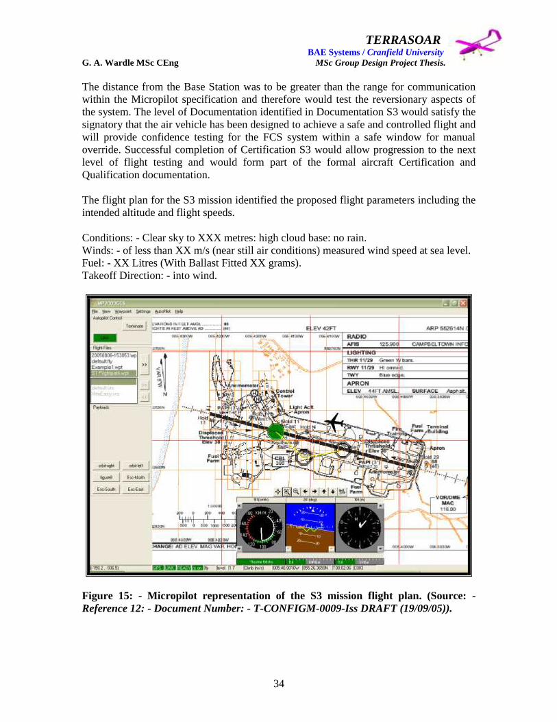
TERRASOAR BAE Systems / Cranfield University G. A. Wardle MSc CEng MSc Group Design Project Thesis.
34
The distance from the Base Station was to be greater than the range for communication
within the Micropilot specification and therefore would test the reversionary aspects of
the system. The level of Documentation identified in Documentation S3 would satisfy the
signatory that the air vehicle has been designed to achieve a safe and controlled flight and
will provide confidence testing for the FCS system within a safe window for manual
override. Successful completion of Certification S3 would allow progression to the next
level of flight testing and would form part of the formal aircraft Certification and
Qualification documentation.
The flight plan for the S3 mission identified the proposed flight parameters including the
intended altitude and flight speeds.
Conditions: - Clear sky to XXX metres: high cloud base: no rain.
Winds: - of less than XX m/s (near still air conditions) measured wind speed at sea level.
Fuel: - XX Litres (With Ballast Fitted XX grams).
Takeoff Direction: - into wind.
Figure 15: - Micropilot representation of the S3 mission flight plan. (Source: -
Reference 12: - Document Number: - T-CONFIGM-0009-Iss DRAFT (19/09/05)).

TERRASOAR BAE Systems / Cranfield University G. A. Wardle MSc CEng MSc Group Design Project Thesis.
35
Table 4: - Mission S3 Test documentation. (Reference 12)
Document Name Issue Status Owner
Design Build Standard 0 A. Barnes
Design Standard 0 A. Barnes
Aircraft PSQS 0 D. Baird
Fuel PSQS 0 V. Hind
Payload PSQS 0 Ra. Cunliffe
Power Gen PSQS 0 Ro. Cunliffe
FCS PSQS 0 B. Currie
Powerplant PSQS 0 D. Adams
Wing EDR Compliance (covering) 0 G. Wardle
Fuel EDR Compliance 0 V. Hind
Payload EDR Compliance 0 Ra. Cunliffe
Power Gen EDR Compliance 0 Ro. Cunliffe
FCS EDR Compliance 0 B. Currie
Fuse EDR Compliance 0 P. Gilligan
U/C EDR Compliance 0 R. Sneddon
Tail & Booms EDR Compliance 0 J. Pennington
Powerplant EDR Compliance 0 D. Adams
Equipment Documentation 0 Ro. Cunliffe
Hazard Analysis (Equipment & Aircraft) 0 D. Baird
Mass/Performance & C of G Statement 0 A. Barnes/J. Pennington
Concession Document 0 TBD
Test Documentation 0 E. Bradley
Mission S4: - Endurance evaluation.
Certification S4 was be the final certification flight of Terrasoar after acceptable S4
testing. S4 would demonstrate an endurance flight capability by performing a takeoff,
agreed flight plan at up to a distance of 3 kilometres from the mission controller (Base
Station) and at an altitude of 700 metres. Followed by controlled approach and landing.
The mission was to be performed using the Micropilot FCS for the sustained airborne
flight with PIC for Takeoff and Landing, with the aircraft repeating the circuit for a 1
hour duration thus demonstrating the Terrasoar‟s endurance capability. This mission was
to conclude flight certification and acceptance trials upon which ownership of the aircraft
and all documentation including the aircraft manuals could be formally handed over to
the customers namely Cranfield University and BAE Systems.
These four missions constituted a much more structured flight clearance program than
that originally envisioned in the first draft of AVT-0215 and were agreed with BAE
Systems Regional Aircraft to enable clearance of the Terrasoar Unmanned Air Vehicle,
and this concludes the requirements capture section of this thesis.
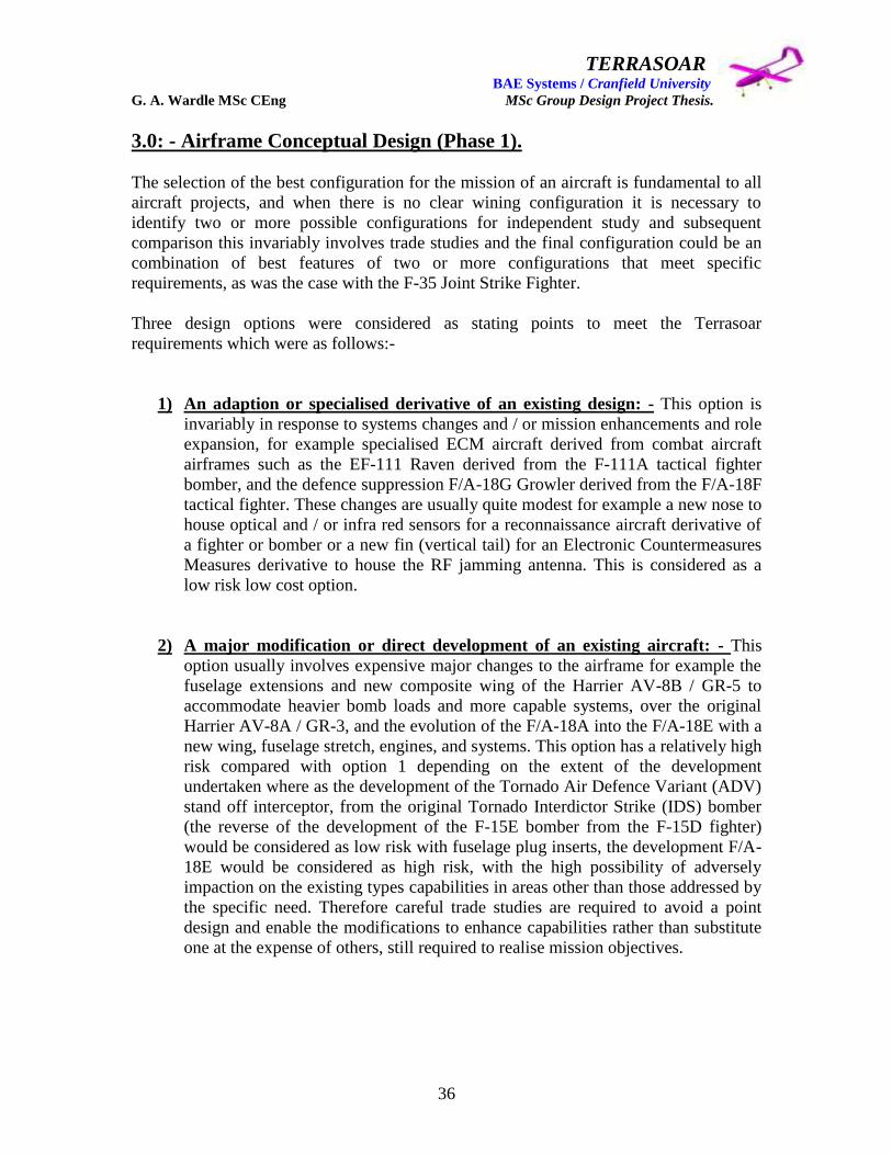
TERRASOAR BAE Systems / Cranfield University G. A. Wardle MSc CEng MSc Group Design Project Thesis.
36
3.0: - Airframe Conceptual Design (Phase 1).
The selection of the best configuration for the mission of an aircraft is fundamental to all
aircraft projects, and when there is no clear wining configuration it is necessary to
identify two or more possible configurations for independent study and subsequent
comparison this invariably involves trade studies and the final configuration could be an
combination of best features of two or more configurations that meet specific
requirements, as was the case with the F-35 Joint Strike Fighter.
Three design options were considered as stating points to meet the Terrasoar
requirements which were as follows:-
1) An adaption or specialised derivative of an existing design: - This option is
invariably in response to systems changes and / or mission enhancements and role
expansion, for example specialised ECM aircraft derived from combat aircraft
airframes such as the EF-111 Raven derived from the F-111A tactical fighter
bomber, and the defence suppression F/A-18G Growler derived from the F/A-18F
tactical fighter. These changes are usually quite modest for example a new nose to
house optical and / or infra red sensors for a reconnaissance aircraft derivative of
a fighter or bomber or a new fin (vertical tail) for an Electronic Countermeasures
Measures derivative to house the RF jamming antenna. This is considered as a
low risk low cost option.
2) A major modification or direct development of an existing aircraft: - This
option usually involves expensive major changes to the airframe for example the
fuselage extensions and new composite wing of the Harrier AV-8B / GR-5 to
accommodate heavier bomb loads and more capable systems, over the original
Harrier AV-8A / GR-3, and the evolution of the F/A-18A into the F/A-18E with a
new wing, fuselage stretch, engines, and systems. This option has a relatively high
risk compared with option 1 depending on the extent of the development
undertaken where as the development of the Tornado Air Defence Variant (ADV)
stand off interceptor, from the original Tornado Interdictor Strike (IDS) bomber
(the reverse of the development of the F-15E bomber from the F-15D fighter)
would be considered as low risk with fuselage plug inserts, the development F/A-
18E would be considered as high risk, with the high possibility of adversely
impaction on the existing types capabilities in areas other than those addressed by
the specific need. Therefore careful trade studies are required to avoid a point
design and enable the modifications to enhance capabilities rather than substitute
one at the expense of others, still required to realise mission objectives.
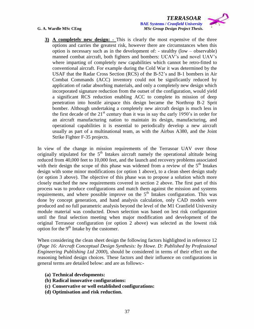
TERRASOAR BAE Systems / Cranfield University G. A. Wardle MSc CEng MSc Group Design Project Thesis.
37
3) A completely new design: - This is clearly the most expensive of the three
options and carries the greatest risk, however there are circumstances when this
option is necessary such as in the development of: - stealthy (low – observable)
manned combat aircraft, both fighters and bombers: UCAV‟s and novel UAV‟s
where imparting of completely new capabilities which cannot be retro-fitted to
conventional aircraft. For example during the Cold War it was determined by the
USAF that the Radar Cross Section (RCS) of the B-52‟s and B-1 bombers in Air
Combat Commands (ACC) inventory could not be significantly reduced by
application of radar absorbing materials, and only a completely new design which
incorporated signature reduction from the outset of the configuration, would yield
a significant RCS reduction enabling ACC to complete its mission of deep
penetration into hostile airspace this design became the Northrop B-2 Sprit
bomber. Although undertaking a completely new aircraft design is much less in
the first decade of the 21st century than it was in say the early 1950‟s in order for
an aircraft manufacturing nation to maintain its design, manufacturing, and
operational capabilities it is essential to periodically develop a new aircraft
usually as part of a multinational team, as with the Airbus A380, and the Joint
Strike Fighter F-35 projects.
In view of the change in mission requirements of the Terrasoar UAV over those
originally stipulated for the 5th
Intakes aircraft namely the operational altitude being
reduced from 40,000 feet to 10,000 feet, and the launch and recovery problems associated
with their design the scope of this phase was widened from a review of the 5th
Intakes
design with some minor modifications (or option 1 above), to a clean sheet design study
(or option 3 above). The objective of this phase was to propose a solution which more
closely matched the new requirements covered in section 2 above. The first part of this
process was to produce configurations and match them against the mission and systems
requirements, and where possible improve on the 5th
Intakes configuration. This was
done by concept generation, and hand analysis calculation, only CAD models were
produced and no full parametric analysis beyond the level of the M1 Cranfield University
module material was conducted. Down selection was based on lest risk configuration
until the final selection meeting when major modification and development of the
original Terrasoar configuration (or option 2 above) was selected as the lowest risk
option for the 9th
Intake by the customer.
When considering the clean sheet design the following factors highlighted in reference 12
(Page 16: Aircraft Conceptual Design Synthesis: by Howe. D: Published by Professional
Engineering Publishing Ltd 2000), should be considered in terms of their effect on the
reasoning behind design choices. These factors and their influence on configurations in
general terms are detailed below: and are as follows:-
(a) Technical developments:
(b) Radical innovative configurations:
(c) Conservative or well established configurations:
(d) Optimisation and risk reduction.

TERRASOAR BAE Systems / Cranfield University G. A. Wardle MSc CEng MSc Group Design Project Thesis.
38
A. Technical developments: - The technical developments which would have the
greatest impact on a small UAV of the Terrasoar‟s scale were confined to the field
of large radio controlled flying models, were reliable and relatively cheap scale
turbofan and turbojet engines have come to be readily available, and the authors
thoughts turned to the possibility of designing a scaled U-2 type aircraft of long
range high altitude (not possible with the MOKI engine), and high endurance with
a more comprehensive fuel system than the 5th
Intakes plastic bag, this would also
obviate the propeller ground clearance requirements, and the very dubious
indexing system.
An other major development was in the field of Flight Control System Avionics,
the XRAY crate was clearly dated from initial inspection and a much more
compact and light weight system could found and was purchased for this project,
although throughout the concept phase the BAE Systems customer representative
Mr Peter Hamilton insisted that space be available for the XRAY crate in all
configurations studied which was primarily due to his involvement in the non-
flying Eclipse program.
Further technical developments which were to play a key role in Terrasoar design
decisions were innovations in manufacturing processes and materials, such as
resin infusion, and a foam sheet material R63.80 which was low temperature
curing foam in sheets 3mm thick and could be used in making wing spars, ribs,
and skins so a light but strong wing could be produced providing tooling costs
could be controlled, as will be seen in section 4 of this thesis manufacturing
tooling cost estimates eventually mitigated against this innovative material
although it has been used successfully on other UAV and manned trainer aircraft
projects more complex than Terrasoar, and could have reduced the weight
problems that were to stalk the Terrasoar in design maturation.
B. Radical innovative configurations: - these are often seen as possessing
significant advantages over more conservative designs for example the radical
Northrop YF-23 Advanced Tactical Fighter (ATF) design compared with the
conservative Lockheed YF-22 ATF design, but as experience demonstrated the
former aircraft (YF-23) was an excellent point design as a stealthy interceptor, but
the latter aircraft (YF-22) was more manoeuvrable and applicable to a wider range
of air combat situations than the YF-23, and it is the Lockheed F/A-22A which
will form the backbone of the USAF ACC fighter arm for the next 40 years and
not the more radical Northrop aircraft. Therefore, radical configurations should
only be considered when their theoretical advantages are relevant to the dominant
requirement in the specification. An other example taken directly from reference
13, is the Wright‟s Flyer which had a foreplane configuration, which had major
advantages in terms of lift generation, but later experience demonstrated that this
configuration had adverse secondary effects which off set the lift advantages for
most subsonic aircraft, and it is more suitable for supersonic flight, or when the
FCS can accommodate a naturally unstable aircraft.

TERRASOAR BAE Systems / Cranfield University G. A. Wardle MSc CEng MSc Group Design Project Thesis.
39
C. Conservative or well established configurations: - These exist for some aircraft
types such as large subsonic transports both military and civilian, for example the
Airbus range of airliners form the A-300 to the A-380 all have moderately swept
wings, with pod turbofan engines hung underneath the wings a wide body
fuselage with the exception of the A-320 and its derivatives, and a single vertical
fin, and all moving horizontal elevator tail, and this configuration with the
exception of the Lockheed Tristar, DC-10, and MD-11 is the prevalent airliner
configuration on both sides of the Atlantic. Military transports follow a
conservative configuration as a functional requirement all have rear loading ramps
and T-tails, or high mounted tails, the former type is seen on the Lockheed C-5
Galaxy, the Airbus 400M, and the Boeing C-17, the latter is seen on the Lockheed
C-130, the AN – 124, and the Transal, all have pod engines either turbofans or
turboprops, and all have high mounted wings to clear the cargo bays. Therefore
configuration selection is straightforward, and the only time two or more different
configurations would be considered would be if there were compelling
requirements to incorporate innovative technological developments, such as the
blended wing body, which is still under research study for both of these
applications, or propfans studied in the late 1970‟s.
D. Optimisation and risk reduction: - The final configuration submitted as the
potential customer solution which eventually progresses through the design
process to detail design and final manufacture, is not necessarily the one which is
determined to be the best form the optimisation process. Indeed a radical solution
may have many attributes to recommend it but the very novelty of the
configuration may mitigate against it on grounds of risk reduction or cost in
changing the operating infrastructure to support the aircraft, this is seen as one of
the reasons the blended wing body airliner has still to catch on, where as the
Airbus A380 still looks conventional and can operate from major airports without
their needing to undertake any major changes. The true cost of the final
configuration will also be a major factor for example a truly mission adaptive
wing currently is still a very expensive option and is confined to research aircraft,
because of their exotic materials, sensors, and actuators, and shear complexity
compared with conventional three section wings (leading edge flap: torsion box:
trailing edge flap).
3.1: - Airframe configuration submissions and design decisions.
With the above points in mind although Phase 1 was opened to consider a completely
new configuration the most likely outcome from this Phase would be a final decision to
rework the existing 5th
Intakes configuration on grounds of cost, time-scale, and facilities
to verify any completely new concept. However even this pessimistic outlook should not
have dampened an opportunity to demonstrate creativity, but unfortunately this was not a
view shared by the majority of the 9th
Intake. An open forum session was held 13th
August 2003, to present alternative configurations to that of the 5th
Intake, to which there
were four original respondents including the author and three who submitted pictures of
existing designs out of thirteen and these are presented below.
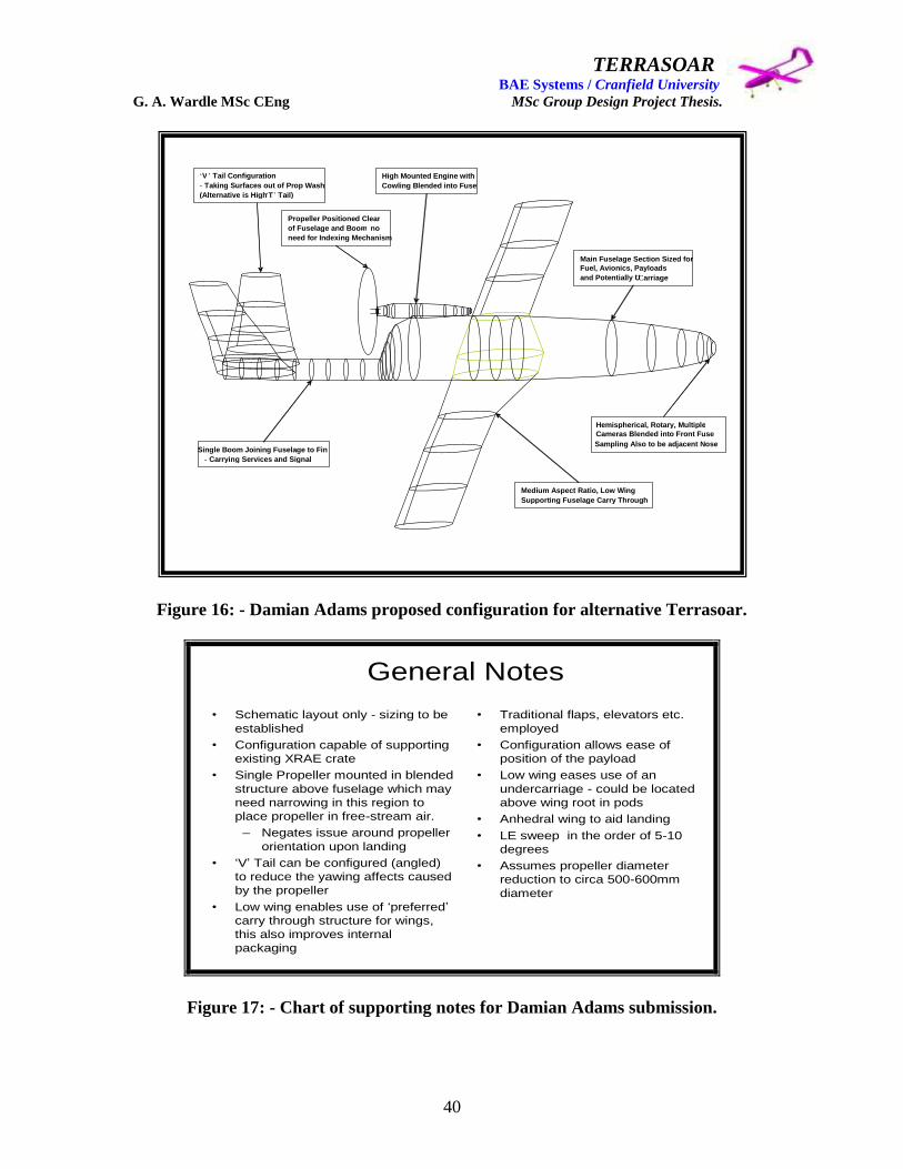
TERRASOAR BAE Systems / Cranfield University G. A. Wardle MSc CEng MSc Group Design Project Thesis.
40
Figure 16: - Damian Adams proposed configuration for alternative Terrasoar.
General Notes
• Schematic layout only - sizing to be
established
• Configuration capable of supporting
existing XRAE crate
• Single Propeller mounted in blended
structure above fuselage which may
need narrowing in this region to
place propeller in free-stream air.
– Negates issue around propeller
orientation upon landing
• ‘V’ Tail can be configured (angled)
to reduce the yawing affects caused
by the propeller
• Low wing enables use of ‘preferred’
carry through structure for wings,
this also improves internal
packaging
• Traditional flaps, elevators etc.
employed
• Configuration allows ease of
position of the payload
• Low wing eases use of an
undercarriage - could be located
above wing root in pods
• Anhedral wing to aid landing
• LE sweep in the order of 5-10
degrees
• Assumes propeller diameter
reduction to circa 500-600mm
diameter
Figure 17: - Chart of supporting notes for Damian Adams submission.
„ V ‟ Tail Configuration - Taking Surfaces out of Prop Wash (Alternative is High „ T ‟ Tail)
Single Boom Joining Fuselage to Fin - Carrying Services and Signal
High Mounted Engine with Cowling Blended into Fuse
Propeller Positioned Clear of Fuselage and Boom - no need for Indexing Mechanism
Medium Aspect Ratio, Low Wing Supporting Fuselage Carry Through
Hemispherical, Rotary, Multiple Cameras Blended into Front Fuse Sampling Also to be adjacent Nose
Main Fuselage Section Sized for Fuel, Avionics, Payloads and Potentially U ‟ Carriage
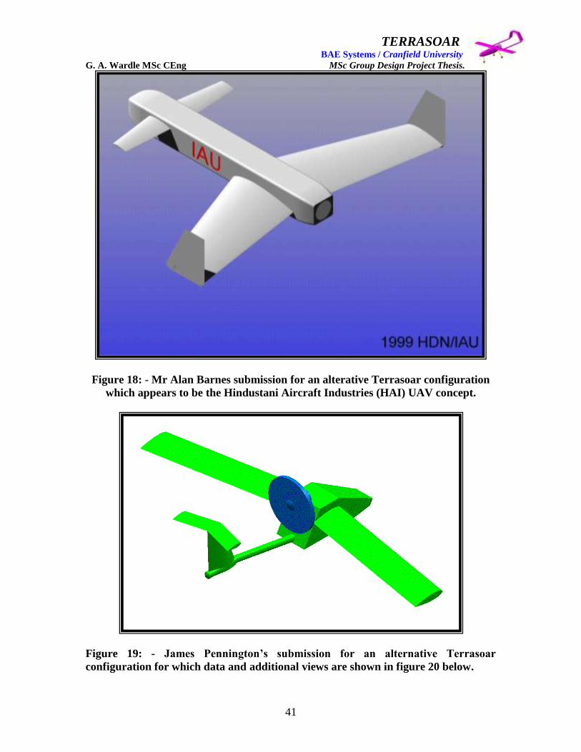
TERRASOAR BAE Systems / Cranfield University G. A. Wardle MSc CEng MSc Group Design Project Thesis.
41
Figure 18: - Mr Alan Barnes submission for an alterative Terrasoar configuration
which appears to be the Hindustani Aircraft Industries (HAI) UAV concept.
Figure 19: - James Pennington‟s submission for an alternative Terrasoar
configuration for which data and additional views are shown in figure 20 below.
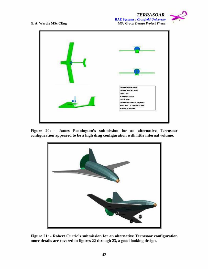
TERRASOAR BAE Systems / Cranfield University G. A. Wardle MSc CEng MSc Group Design Project Thesis.
42
Figure 20: - James Pennington‟s submission for an alternative Terrasoar
configuration appeared to be a high drag configuration with little internal volume.
Figure 21: - Robert Currie‟s submission for an alternative Terrasoar configuration
more details are covered in figures 22 through 23, a good looking design.
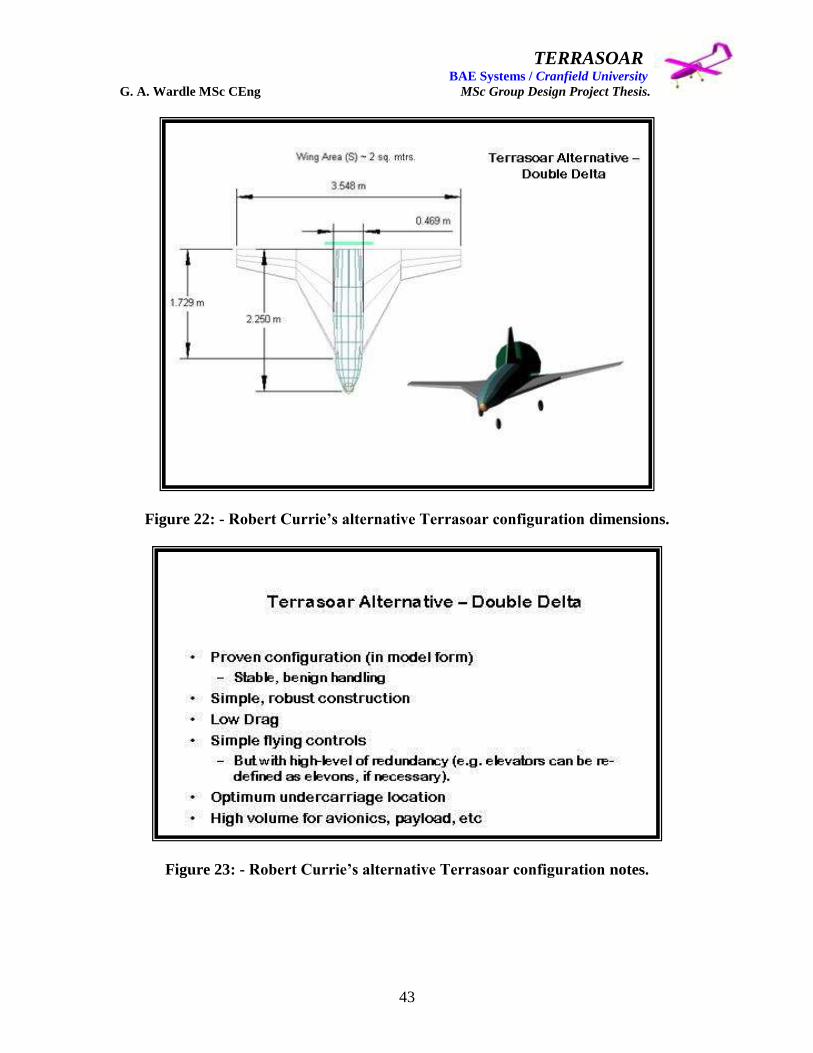
TERRASOAR BAE Systems / Cranfield University G. A. Wardle MSc CEng MSc Group Design Project Thesis.
43
Figure 22: - Robert Currie‟s alternative Terrasoar configuration dimensions.
Figure 23: - Robert Currie‟s alternative Terrasoar configuration notes.
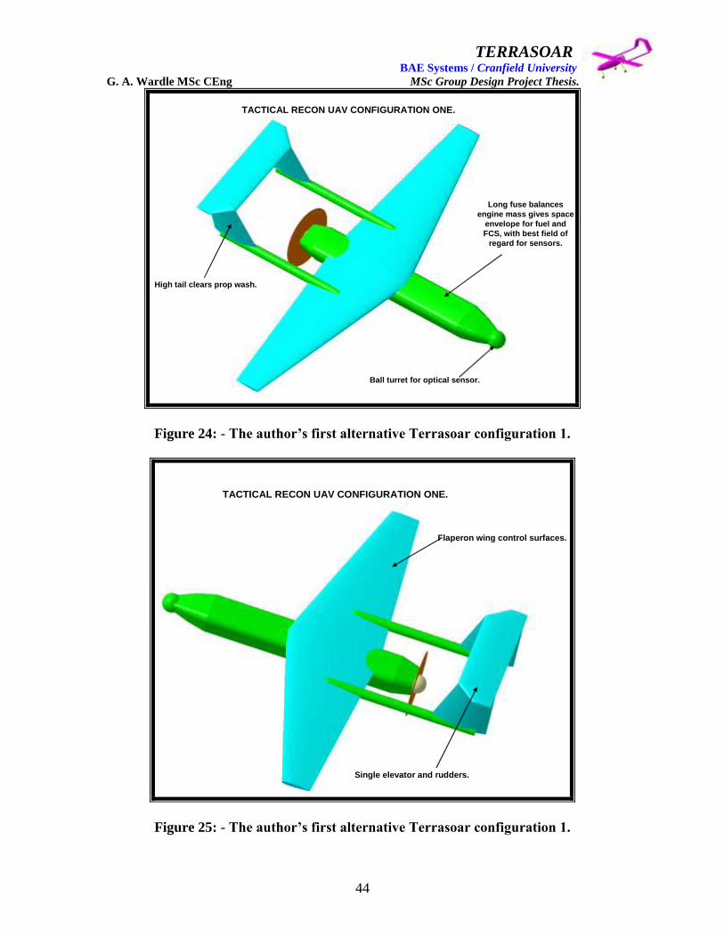
TERRASOAR BAE Systems / Cranfield University G. A. Wardle MSc CEng MSc Group Design Project Thesis.
44
TACTICAL RECON UAV CONFIGURATION ONE.
High tail clears prop wash.
Long fuse balances
engine mass gives space
envelope for fuel and
FCS, with best field of
regard for sensors.
Ball turret for optical sensor.
Figure 24: - The author‟s first alternative Terrasoar configuration 1.
TACTICAL RECON UAV CONFIGURATION ONE.
Flaperon wing control surfaces.
Single elevator and rudders.
Figure 25: - The author‟s first alternative Terrasoar configuration 1.

TERRASOAR BAE Systems / Cranfield University G. A. Wardle MSc CEng MSc Group Design Project Thesis.
45
GENERAL FEATURES OF CONFIGURATION 1 NEW BUILD.
Wing span:- 4.0 m
Root Chord:- 1.0 m
Tip Chord:- 300 mm
L/E Sweep:- 15 deg
O/A Length:- 3.5 m
Fuse width max:- 300 mm
Propeller diameter:- 700 mm
High wing, high tail, twin boom configuration with single propeller. Tandem
undercarriage units mounted in fuselage with wing tip outriggers or
reinforced wing tip snubbers fitted. Terrasoar engine and flight control crate
fitted and wing joints at the boom interfaces.
A smaller wing taper ratio in this case 0.3, decreases the moment arm
from the root to the centre of pressure maintaining the same lift, and
decreases the bending moment at the wing root, resulting in a lighter wing
structure.
Figure 26: - Alternative Terrasoar configuration 1 key design feature notes.
Figure 27: - The author‟s second alternative Terrasoar configuration 2.
Low drag slender fuselage configuration.
Main undercarriage stored in rear of wing pods mounted on
removable wing.
High lift wing reducing landing speed and a
lighter wing structure.

TERRASOAR BAE Systems / Cranfield University G. A. Wardle MSc CEng MSc Group Design Project Thesis.
46
Figure 28: - The author‟s second alternative Terrasoar configuration 2.
GENERAL FEATURES OF CONFIGURATION 2 NEW BUILD.
Wing span:- 5.0 m
Root Chord:- 1.0 m
Tip Chord:- 500 mm
L/E Sweep:- 15 deg
O/A Length:- 4.7 m
Fuse diameter :- 300 mm
Propeller diameter:- 800 mm
High wing, medium tail, long fuselage configuration with single propeller.
Main undercarriage units mounted in wing pods nose unit in fuselage, uses
Terrasoar engine and flight control crate, with sensors in nose and wing
pods.
A larger wing taper ratio in this case 0.5, than configuration one but still
decreases the moment arm from the root to the centre of pressure
maintaining the same lift, and decreases the bending moment at the wing
root, resulting in a lighter wing structure.
Figure 29: - Alternative Terrasoar configuration 2 key design feature notes.
TACTICAL RECON UAV CONFIGURATION TWO
The twin tail offers the same amount of lateral stability for a smaller size than a single tail fin.
Engine air cooling from meshed annulus.

TERRASOAR BAE Systems / Cranfield University G. A. Wardle MSc CEng MSc Group Design Project Thesis.
47
TACTICAL RECON UAV CONFIGURATION THREE.
Figure 30: - The author‟s third alternative Terrasoar configuration 3.
TACTICAL RECON UAV CONFIGURATION THREE.
Figure 31: - The author‟s third alternative Terrasoar configuration 3.
High mounted jet engine
out of ground FOD field.
Larger fuselage configuration enabling a larger fuel tank to be
incorporated.
The twin tail keeps the rudders out of the jet wash.

TERRASOAR BAE Systems / Cranfield University G. A. Wardle MSc CEng MSc Group Design Project Thesis.
48
GENERAL FEATURES OF CONFIGURATION 3 NEW BUILD.
Wing span:- 5.0 m
Root Chord:- 1.0 m
Tip Chord:- 500 mm
L/E Sweep:- 15 deg
O/A Length:- 4.6 m
Fuse diameter :- 420 mm
Propeller diameter:- 800 mm
Pod jet version of configuration 2, this high wing, medium tail, large
fuselage configuration has twin tails. Main undercarriage units mounted in
wing pods nose unit in fuselage, uses jet engine and flight control crate,
with sensors in nose and wing pods.
A wing taper ratio of 0.5, decreases the moment arm from the root to the
centre of pressure maintaining the same lift, and decreases the bending
moment at the wing root, resulting in a lighter wing structure.
Figure 32: - Alternative Terrasoar configuration 3 key design feature notes.
TACTICAL RECON UAV CONFIGURATION FOUR.
Figure 33: - The author‟s fourth alternative Terrasoar configuration 4.
Main undercarriage stored in rear of wing pods mounted on
removable faired in wing.
The large fuselage configuration enabled a larger fuel tank to be incorporated and a 25kg payload
to be carried.

TERRASOAR BAE Systems / Cranfield University G. A. Wardle MSc CEng MSc Group Design Project Thesis.
49
TACTICAL RECON UAV CONFIGURATION FOUR.
Figure 34: - The author‟s fourth alternative Terrasoar configuration 4.
GENERAL FEATURES OF CONFIGURATION 4 NEW BUILD.
Wing span:- 5.0 m
Root Chord:- 1.0 m
Tip Chord:- 500 mm
L/E Sweep:- 15 deg
O/A Length:- 4.6 m
Fuse diameter :- 420 mm
Propeller diameter:- 800 mm
Large fuselage section version of configuration 2, this high wing, medium
tail, long fuselage configuration with single propeller. Main undercarriage
units mounted in wing pods nose unit in fuselage, uses Terrasoar engine
and flight control crate, with sensors in nose and wing pods.
A wing taper ratio of 0.5, decreases the moment arm from the root to the
centre of pressure maintaining the same lift, and decreases the bending
moment at the wing root, resulting in a lighter wing structure.
Figure 35: - Alternative Terrasoar configuration 4 key design feature notes.
The twin tail offers the same amount of lateral stability for a smaller size than a single tail fin.
The original Terrasoar engine with extended prop shaft is
incorporated in this design.

TERRASOAR BAE Systems / Cranfield University G. A. Wardle MSc CEng MSc Group Design Project Thesis.
50
TACTICAL RECON UAV CONFIGURATION FIVE.
Figure 36: - The author‟s fifth alternative Terrasoar configuration 5.
TACTICAL RECON UAV CONFIGURATION FIVE.
Figure 37: - The author‟s fifth alternative Terrasoar configuration 5.
Imbedded jet engine to reduce drag fitted with short side pod ducts.
Fuselage blanking of the short side pod ducts would be a problem.
Empennage control actuators near hot exhaust would be a problem.

TERRASOAR BAE Systems / Cranfield University G. A. Wardle MSc CEng MSc Group Design Project Thesis.
51
GENERAL FEATURES OF CONFIGURATION 5 NEW BUILD.
Wing span:- 5.0 m
Root Chord:- 1.0 m
Tip Chord:- 500 mm
L/E Sweep:- 15 deg
O/A Length:- 4.5 m
Fuse diameter :- 420 mm
Propeller diameter:- 800 mm
Single tail jet version of configuration 4, this high wing, medium tail, long
fuselage configuration. Main undercarriage units mounted in wing pods
and nose unit in fuselage, uses jet engine in rear fuselage with aft intakes,
flight control crate, with sensors in nose and wing pods.
A wing taper ratio of 0.5, decreases the moment arm from the root to the
centre of pressure maintaining the same lift, and decreases the bending
moment at the wing root, resulting in a lighter wing structure.
Figure 38: - Alternative Terrasoar configuration 5 key design feature notes.
Author’s configurations general notes.
• All configurations have flaps, ailerons, and elevators.
• Only one conventional tail configuration was considered.
• Aircraft configurations 3 to 5 have tricycle undercarriage arrangement.
• All configurations have been sized based on Terrasoar overall
dimensions, and have been modified to meet the new mission
requirements and need parametric analysis.
• The prop size has been reduced to diameters of 700 mm - 800 mm to
reflect the new mission requirements and needs parametric analysis, also
no sizing has been done on the jet configurations.
•These are all general arrangement CATIA V5 models and are only
intended for configuration concept capture and not intended to form the
basis of surface models for manufacture.
Figure 39: - Overview design notes on all of the authors alternative Terrasoar
configurations.

TERRASOAR BAE Systems / Cranfield University G. A. Wardle MSc CEng MSc Group Design Project Thesis.
52
Figure 40: - Mr Craig Carr‟s alternative Terrasoar configuration a picture of the
Pioneer light UAV.
Figure 41: - Mr Robert Sneddon‟s alternative Terrasoar configuration the Boeing
Scan Eagle light UAV.

TERRASOAR BAE Systems / Cranfield University G. A. Wardle MSc CEng MSc Group Design Project Thesis.
53
Co
nfi
gu
rati
on
Do
wn
Sele
ct
Usin
g W
eig
hte
d D
ecis
ion
Makin
g
0
50
10
0
15
0
20
0
25
0
30
0
35
0
40
0
45
0
50
0Max
GW1
GW2
GW3
GW4
GW5
RC1
AB1
CC1
PG1
RS1
RS2
DA1
JP1
Co
nfi
gu
rati
on
Weighted Score
Dete
cta
bili
ty (
Lo
w N
ois
e, V
isib
ility
)
Siz
e
Ge
ne
ral D
esig
n -
Aesth
etics
Rob
ustn
ess (
Han
dla
bili
ty)
Paylo
ad A
ccess -
Lo
ad
/ U
nlo
ad
Lo
w C
ost
Relia
bili
ty / S
up
po
rtab
ility
Lo
w M
ass
Aero
dyna
mic
Perf
orm
an
ce / R
an
ge
Man
ufa
ctu
rab
ility
Paylo
ad C
arr
iag
e a
nd
Deliv
ery
Air
wort
hin
ess
Pro
ject D
ura
tion
AG
RE
ED
CU
T-O
FF
SC
OR
E
Fig
ure
42:
- C
on
figu
rati
on
dow
n s
elec
tion
ch
art
at
the
end
of
the
init
ial
con
cep
t st
ud
y p
hase
.

TERRASOAR BAE Systems / Cranfield University G. A. Wardle MSc CEng MSc Group Design Project Thesis.
54
Weig
ht
Based
Decis
ion
Makin
g -
To
tals
Su
mm
ary
Max
GW
1G
W2
GW
3G
W4
GW
5R
C1
AB
1C
C1
PG
1R
S1
RS
2D
A1
JP
1
Att
rib
ute
Weighting
Maximum
Available
Score
Total
Total
Total
Total
Total
Total
Total
Total
Total
Total
Total
Total
Total
Pro
ject
Dura
tion
13
65
52
39
26
39
26
26
39
52
52
26
39
39
39
Airw
ort
hin
ess
12
60
48
48
36
48
48
48
48
48
48
24
48
48
48
Payl
oad C
arr
iage a
nd D
eliv
ery
11
55
44
33
33
44
44
44
44
44
33
44
44
44
44
Manufa
ctura
bili
ty10
50
30
30
30
30
40
30
40
40
40
30
40
40
40
Aero
dyn
am
ic P
erf
orm
ance
/ R
ange
945
36
36
27
36
36
27
36
36
27
18
36
27
27
Low
Mass
840
16
24
24
16
24
24
32
24
16
24
32
24
32
Relia
bili
ty / S
upport
abili
ty7
35
28
21
14
21
14
21
14
28
28
14
28
28
28
Low
Cost
630
24
12
612
612
12
24
24
12
24
18
24
Payl
oad A
ccess
- L
oad / U
nlo
ad
525
15
15
15
15
15
15
15
15
15
20
15
15
15
Robust
ness
(H
andla
bili
ty)
420
12
12
812
812
12
12
16
816
12
16
Genera
l Desi
gn -
Aest
hetic
s3
15
66
66
612
12
63
612
99
Siz
e2
10
66
66
66
66
64
66
6
Dete
ctabili
ty (
Low
Nois
e, V
isib
ility
)1
53
31
31
33
33
23
33
Tota
l455
320
285
232
288
274
280
313
338
311
232
343
313
331
Tota
l as
% o
f B
est
Typ
e93
83
68
84
80
82
91
99
91
68
100
91
97
Tota
l as
% o
f M
ax
Ava
ilable
70
63
51
63
60
62
69
74
68
51
75
69
73
CH
EC
K T
HA
T A
LL A
TT
RIB
UT
ES
AR
E C
HA
RT
ED
AG
RE
ED
CU
T-O
FF
SC
OR
E300
300
300
300
300
300
300
300
300
300
300
300
300
300
300
Tab
le 5
: -
Con
figu
rati
on
dow
n s
elec
tion
dec
isio
n m
ak
ing f
or
the
init
ial
con
cep
t st
ud
y p
hase
.
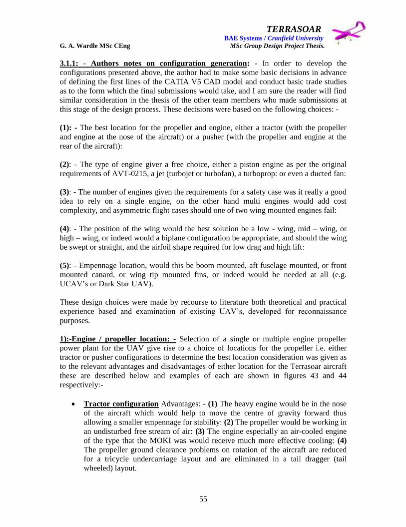
TERRASOAR BAE Systems / Cranfield University G. A. Wardle MSc CEng MSc Group Design Project Thesis.
55
3.1.1: - Authors notes on configuration generation: - In order to develop the
configurations presented above, the author had to make some basic decisions in advance
of defining the first lines of the CATIA V5 CAD model and conduct basic trade studies
as to the form which the final submissions would take, and I am sure the reader will find
similar consideration in the thesis of the other team members who made submissions at
this stage of the design process. These decisions were based on the following choices: -
(1): - The best location for the propeller and engine, either a tractor (with the propeller
and engine at the nose of the aircraft) or a pusher (with the propeller and engine at the
rear of the aircraft):
(2): - The type of engine giver a free choice, either a piston engine as per the original
requirements of AVT-0215, a jet (turbojet or turbofan), a turboprop: or even a ducted fan:
(3): - The number of engines given the requirements for a safety case was it really a good
idea to rely on a single engine, on the other hand multi engines would add cost
complexity, and asymmetric flight cases should one of two wing mounted engines fail:
(4): - The position of the wing would the best solution be a low - wing, mid – wing, or
high – wing, or indeed would a biplane configuration be appropriate, and should the wing
be swept or straight, and the airfoil shape required for low drag and high lift:
(5): - Empennage location, would this be boom mounted, aft fuselage mounted, or front
mounted canard, or wing tip mounted fins, or indeed would be needed at all (e.g.
UCAV‟s or Dark Star UAV).
These design choices were made by recourse to literature both theoretical and practical
experience based and examination of existing UAV‟s, developed for reconnaissance
purposes.
1):-Engine / propeller location: - Selection of a single or multiple engine propeller
power plant for the UAV give rise to a choice of locations for the propeller i.e. either
tractor or pusher configurations to determine the best location consideration was given as
to the relevant advantages and disadvantages of either location for the Terrasoar aircraft
these are described below and examples of each are shown in figures 43 and 44
respectively:-
Tractor configuration Advantages: - (1) The heavy engine would be in the nose
of the aircraft which would help to move the centre of gravity forward thus
allowing a smaller empennage for stability: (2) The propeller would be working in
an undisturbed free stream of air: (3) The engine especially an air-cooled engine
of the type that the MOKI was would receive much more effective cooling: (4)
The propeller ground clearance problems on rotation of the aircraft are reduced
for a tricycle undercarriage layout and are eliminated in a tail dragger (tail
wheeled) layout.

TERRASOAR BAE Systems / Cranfield University G. A. Wardle MSc CEng MSc Group Design Project Thesis.
56
Tractor configuration Disadvantages: - (1) The propeller slipstream would
disturb the quality of the airflow over the fuselage and wing root: (2) The
increased velocity and flow turbulence over the fuselage due to the propeller
slipstream would increase the local skin friction on the fuselage increasing drag:
(3) The field of regard for any sensors in a single engine configuration would be
reduced because these would need to be mounted either above, or below, the
fuselage or in a wing nacelle and all of these positions would have resulted in
some obscuration from the fuselage itself.
Pusher configuration Advantages: - (1) A clean high quality airflow would
predominate over the wing and fuselage: (2) The field of regard for sensors would
be vastly improved by mounting them in the nose of the aircraft: (3) The aft
mounting of the propeller in the single engine configuration arrests flow
separation at the rear of the fuselage by drawing air in to the rear fuselage and
thus producing a pressure gradient favourable flow retention, this results in a
steeper closure angle for the rear fuselage, which can be made shorter reducing
the wetted surface area and drag: (4) Reduced noise and vibration for the payload
and avionics equipment: (5) Simplification of the fuel system as the fuel tank
could be positioned immediately in front of the engine (separated by a fire wall)
and fuel pipes run directly to the engine instead of convoluted paths under the
avionics bay which would need screening for its entire length.
Pusher configuration Disadvantages: - (1) A heavy engine at the rear of the
aircraft would result in a rearward shift in the centre of gravity (c.g.) of the
aircraft thus reducing longitudinal stability of the configuration, which would
require countering with more of the fuselage ahead of the wing or a heavy
payload / systems in the forward fuselage, or even additional / larger longitudinal
control surfaces: (2) Long undercarriage is usually required enable the clearance
of the propeller from the ground during aircraft rotation on take-off, and to protect
the propeller from damage from FOD on landing: (3) Ensuring a clear flow of
cooling air to the engine would be more difficult with a rear mounted pusher
configuration which would require ducting, complicating the design, of the
fuselage, and this would be a problem on the Terrasoar with the powerful air –
cooled MOKI engine (4) Location and integration of empennage control surface
actuators where the empennage is located at the rear of the fuselage, would be
difficult therefore on low cost UAV‟s the twin boom empennage configuration
predominates, with the exception of the Scan Eagle and a few other very small
UAV‟s.
In spite of the disadvantages the pusher configuration was selected for all propeller
versions of alternative Terrasoar proposed by the author because the field of regard for
the sensor payload was deemed a paramount requirement by the author.

TERRASOAR BAE Systems / Cranfield University G. A. Wardle MSc CEng MSc Group Design Project Thesis.
57
Figure 43: - Raptor Tractor propeller UAV configuration used by NASA.
(AeroDYNAMIC Version 3.0: AIAA EDUCATION SERIES CD-ROM 2003)
Figure 44: - Predator Pusher propeller UAV configuration used by the USAF.
(AeroDYNAMIC Version 3.0: AIAA EDUCATION SERIES CD-ROM 2003)
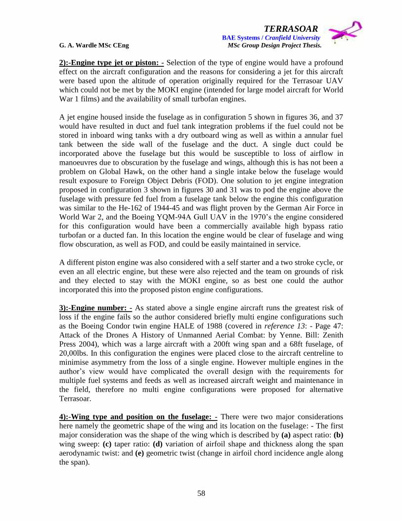
TERRASOAR BAE Systems / Cranfield University G. A. Wardle MSc CEng MSc Group Design Project Thesis.
58
2):-Engine type jet or piston: - Selection of the type of engine would have a profound
effect on the aircraft configuration and the reasons for considering a jet for this aircraft
were based upon the altitude of operation originally required for the Terrasoar UAV
which could not be met by the MOKI engine (intended for large model aircraft for World
War 1 films) and the availability of small turbofan engines.
A jet engine housed inside the fuselage as in configuration 5 shown in figures 36, and 37
would have resulted in duct and fuel tank integration problems if the fuel could not be
stored in inboard wing tanks with a dry outboard wing as well as within a annular fuel
tank between the side wall of the fuselage and the duct. A single duct could be
incorporated above the fuselage but this would be susceptible to loss of airflow in
manoeuvres due to obscuration by the fuselage and wings, although this is has not been a
problem on Global Hawk, on the other hand a single intake below the fuselage would
result exposure to Foreign Object Debris (FOD). One solution to jet engine integration
proposed in configuration 3 shown in figures 30 and 31 was to pod the engine above the
fuselage with pressure fed fuel from a fuselage tank below the engine this configuration
was similar to the He-162 of 1944-45 and was flight proven by the German Air Force in
World War 2, and the Boeing YQM-94A Gull UAV in the 1970‟s the engine considered
for this configuration would have been a commercially available high bypass ratio
turbofan or a ducted fan. In this location the engine would be clear of fuselage and wing
flow obscuration, as well as FOD, and could be easily maintained in service.
A different piston engine was also considered with a self starter and a two stroke cycle, or
even an all electric engine, but these were also rejected and the team on grounds of risk
and they elected to stay with the MOKI engine, so as best one could the author
incorporated this into the proposed piston engine configurations.
3):-Engine number: - As stated above a single engine aircraft runs the greatest risk of
loss if the engine fails so the author considered briefly multi engine configurations such
as the Boeing Condor twin engine HALE of 1988 (covered in reference 13: - Page 47:
Attack of the Drones A History of Unmanned Aerial Combat: by Yenne. Bill: Zenith
Press 2004), which was a large aircraft with a 200ft wing span and a 68ft fuselage, of
20,00lbs. In this configuration the engines were placed close to the aircraft centreline to
minimise asymmetry from the loss of a single engine. However multiple engines in the
author‟s view would have complicated the overall design with the requirements for
multiple fuel systems and feeds as well as increased aircraft weight and maintenance in
the field, therefore no multi engine configurations were proposed for alternative
Terrasoar.
4):-Wing type and position on the fuselage: - There were two major considerations
here namely the geometric shape of the wing and its location on the fuselage: - The first
major consideration was the shape of the wing which is described by (a) aspect ratio: (b)
wing sweep: (c) taper ratio: (d) variation of airfoil shape and thickness along the span
aerodynamic twist: and (e) geometric twist (change in airfoil chord incidence angle along
the span).

TERRASOAR BAE Systems / Cranfield University G. A. Wardle MSc CEng MSc Group Design Project Thesis.
59
(a) The aspect ratio AR of the wing was given by dividing the total reference wing span
i.e. tip to tip squared b2 by the wing area S and an aspect ratio between 6 and 10 was
considered adequate for the missions envisaged for this UAV, because this falls in the
range for low speed subsonic transports, where as the aspect ratio for a fighter is between
2 and 5, and for gliders its 10 to 15.
(b) There were two sweep angles of importance when considering wing geometry,
namely the leading edge sweep angle LE and the sweep angle of the quarter-chord line
c / 4 as shown in figure 45 below.
Figure 45: - The major parameters of wing definitions. (Reference 14: - Whitford R:
Fundamentals of Fighter Design: Airlife Publishing Ltd: 2000.)
The leading – edge sweep angle is of most relevance to supersonic aircraft designs
because in order to reduce wave drag at supersonic speeds, the leading edge should be
swept behind the Mach cone, and the quarter-chord line is of relevance to high-speed
subsonic aircraft flying in the transonic region neither case was applicable to the
Terrasoar aircraft so no in depth study was made for these concepts, or in the as built
Terrasoar design.
c /4
S
b / 2
cr
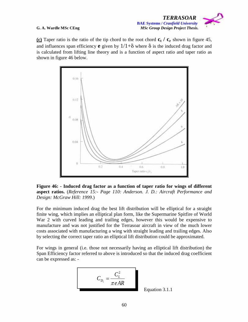
TERRASOAR BAE Systems / Cranfield University G. A. Wardle MSc CEng MSc Group Design Project Thesis.
60
(c) Taper ratio is the ratio of the tip chord to the root chord ct / cr shown in figure 45,
and influences span efficiency e given by 1/1+ where is the induced drag factor and
is calculated from lifting line theory and is a function of aspect ratio and taper ratio as
shown in figure 46 below.
Figure 46: - Induced drag factor as a function of taper ratio for wings of different
aspect ratios. (Reference 15:- Page 110: Anderson. J. D.: Aircraft Performance and
Design: McGraw Hill: 1999.)
For the minimum induced drag the best lift distribution will be elliptical for a straight
finite wing, which implies an elliptical plan form, like the Supermarine Spitfire of World
War 2 with curved leading and trailing edges, however this would be expensive to
manufacture and was not justified for the Terrasoar aircraft in view of the much lower
costs associated with manufacturing a wing with straight leading and trailing edges. Also
by selecting the correct taper ratio an elliptical lift distribution could be approximated.
For wings in general (i.e. those not necessarily having an elliptical lift distribution) the
Span Efficiency factor referred to above is introduced so that the induced drag coefficient
can be expressed as: -
Equation 3.1.1
ARe
CC L
Di
2

TERRASOAR BAE Systems / Cranfield University G. A. Wardle MSc CEng MSc Group Design Project Thesis.
61
Where: - e = 1 for elliptical loading:
e < 1 for non elliptical loading:
(typically 0.85 < e <0.95)
Therefore total wing drag is composed of two components which are profile drag form
skin friction plus pressure, and induced drag so the drag coefficient can be expressed as
follows: -
Equation 3.1.2
Referring to figure 45 for an aspect ratio of for example 7.0, in the bottom half of the 6 to
10 aspect ratio range for this type of aircraft, the minimum value of = 0.005 at a taper
ratio of approximately 0.3, therefore a tapered wing of AR = 7 and a taper ratio of 0.3
would have an induced drag only 0.5% greater than would an elliptical wing of the same
physical size. This justified to the author further consideration of tapered wings on all of
the configurations submitted for both the first and second stages of the concept design
phase of this project.
The choice of taper ratio (defined as = ct / cr = 1 for a rectangular wing) for each
configuration was based on the following factors (covered in depth in reference 13 pages
423 – 424) namely: -
(1) Reduced wing weight over that of a simple rectangular wing: - because as the
taper ratio is reduced the centre of pressure moves closer to the wing root, and therefore
the moment arm from the wing root to the centre of pressure decreases, and thus the
bending moment at the root decreases but the lift remains the same. The net result is that
the wing structure could be made lighter by using a taper ratio less than 1.
(2) Flow separation behaviour: - low taper ratio wings exhibit undesirable flow
separation behaviour and stall behaviour. In the case of a rectangular wing = 1, flow
separation occurs in the root region which has the advantage of creating flow trails down
stream of the wing root resulting in buffeting of the horizontal tail which gives a stall
warning to the aircraft pilot. Also for the rectangular wing the flow at the tip region is
still attached therefore the ailerons usually located in the region of the wingtips would
have full authority.
InducedProfileTotal
ARe
CcC L
dD
2

TERRASOAR BAE Systems / Cranfield University G. A. Wardle MSc CEng MSc Group Design Project Thesis.
62
As the taper ratio decreases the region where flow separation first develops moves
outwards towards the wing tips, and where = 0.5 the region of separation is about half
of the semi – span, and clear of both the wing root and tip ailerons. But when the taper
ratio is reduced to = 0 the stall region is initiated at the tip resulting in loss of aileron
control authority which would be unacceptable for a manned or unmanned aircraft.
Therefore a compromise between the structural benefit a small taper ratio and the
aerodynamic benefits of a large taper ratio was employed in all configuration studies in
this phase of the project, however this concept was not adopted on the as built Terrasoar
design at the insistence of the manufacturing and aerodynamic leads, on grounds cost and
complexity.
(d) A common feature for many aircraft including general aviation aircraft and some
UAV‟s such as Global Hawk is a variation of airfoil section along the wing span, where
one airfoil section is used at the wing root, and a different one is used at the wing tip with
the sections in between the root and tip being a linear interpolation between the root and
tip sections, and this is called aerodynamic twist. Where this is applied the root sections
are relatively thick (in the order of 15% to 17%), and the wing section tapers to a thinner
section at the tip (usually about 12%). The reasons for imparting this aerodynamic twist
are as follows: - (1) structural: (2) aerodynamic: (3) and wing internal capacity.
(1) The structural reasoning for this is that the bending moment is greatest at the wing
root and a thicker root airfoil section permits the design of thicker wing skins and spars at
the root imparting grater structural strength to this region of the wing.
(2) The aerodynamic reasoning is that a 17% airfoil section will stall at a lower angle of
attack than a 12% airfoil therefore if the wing airfoil section tapers from 17% thickness at
the root to 12% thickness at the tip the wing will stall first at the root, maintaining
attached flow at tip retaining the effectiveness of the ailerons at the tips because they are
still in the attached flow region. Also buffeting occurs at the wing root in stall conditions
for such an aerodynamically twisted wing and this buffeting act‟s as an early indicator to
the pilot that the aircraft is stalling enabling recovery to be attempted with all control
surfaces available.
(3) The capacity benefit comes from the thicker wing root section being employed for
internal wing fuel tanks, increasing range without losing cabin volume.
Although these benefits were explained to the team and adopted for the author‟s initial
configuration studies the manufacturing, and aerodynamic leads felt this was too much
effort would be required to produce such a wing and this concept was not adopted on the
as built Terrasoar design.
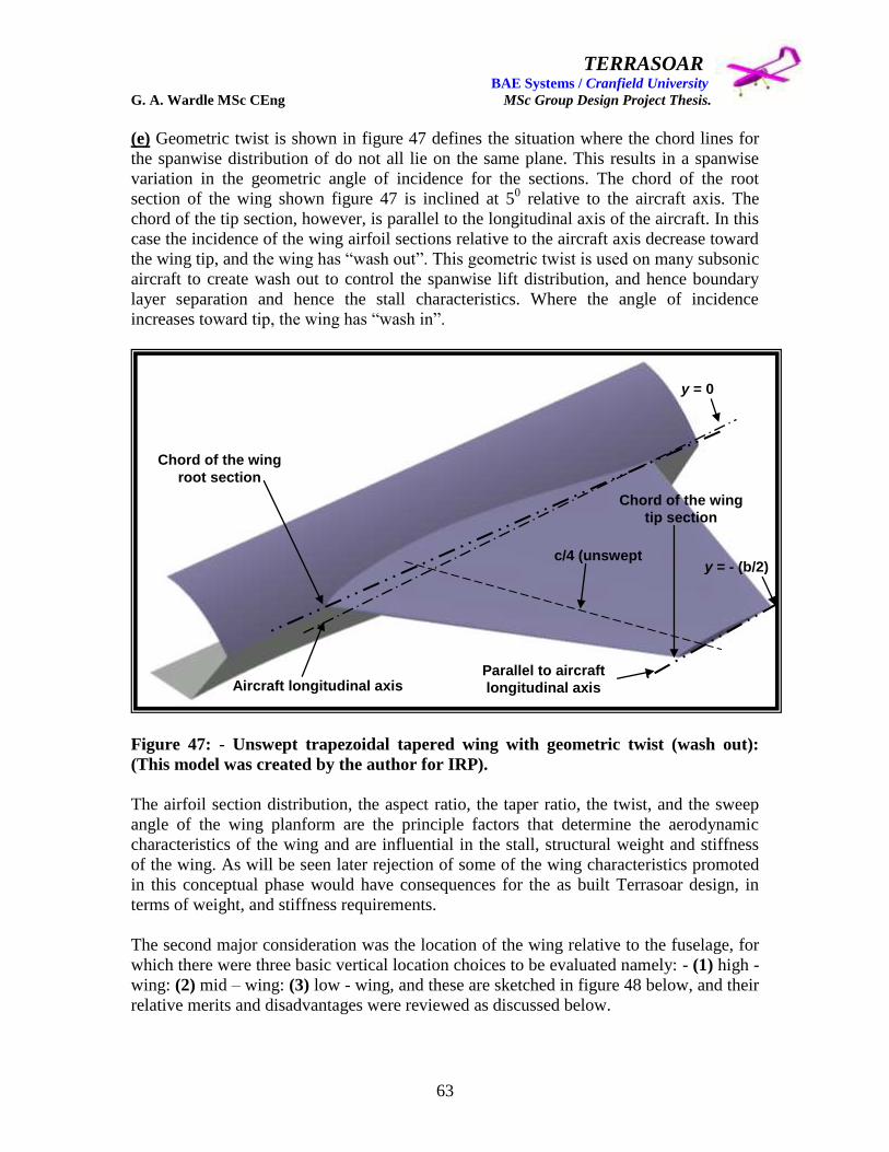
TERRASOAR BAE Systems / Cranfield University G. A. Wardle MSc CEng MSc Group Design Project Thesis.
63
(e) Geometric twist is shown in figure 47 defines the situation where the chord lines for
the spanwise distribution of do not all lie on the same plane. This results in a spanwise
variation in the geometric angle of incidence for the sections. The chord of the root
section of the wing shown figure 47 is inclined at 50 relative to the aircraft axis. The
chord of the tip section, however, is parallel to the longitudinal axis of the aircraft. In this
case the incidence of the wing airfoil sections relative to the aircraft axis decrease toward
the wing tip, and the wing has “wash out”. This geometric twist is used on many subsonic
aircraft to create wash out to control the spanwise lift distribution, and hence boundary
layer separation and hence the stall characteristics. Where the angle of incidence
increases toward tip, the wing has “wash in”.
Figure 47: - Unswept trapezoidal tapered wing with geometric twist (wash out):
(This model was created by the author for IRP).
The airfoil section distribution, the aspect ratio, the taper ratio, the twist, and the sweep
angle of the wing planform are the principle factors that determine the aerodynamic
characteristics of the wing and are influential in the stall, structural weight and stiffness
of the wing. As will be seen later rejection of some of the wing characteristics promoted
in this conceptual phase would have consequences for the as built Terrasoar design, in
terms of weight, and stiffness requirements.
The second major consideration was the location of the wing relative to the fuselage, for
which there were three basic vertical location choices to be evaluated namely: - (1) high -
wing: (2) mid – wing: (3) low - wing, and these are sketched in figure 48 below, and their
relative merits and disadvantages were reviewed as discussed below.
Chord of the wing
root section
Chord of the wing
tip section
c/4 (unswept
Aircraft longitudinal axis Parallel to aircraft
longitudinal axis
y = 0
y = - (b/2)

TERRASOAR BAE Systems / Cranfield University G. A. Wardle MSc CEng MSc Group Design Project Thesis.
64
Figure 48: - Sketches for the comparison of high – wing, mid – wing and low – wing
configurations after Anderson .D. John reference 13.
(a) High – wing position: - This position for the wing is commonly found on large civil
and military cargo transports and small commuter airliners such as the BAe 146, and
enables the fuselage to be placed lower to the ground which simplifies loading in the case
of transports. This configuration enables the whole fuselage section to be used for cargo
stowage without interruption from the wing box, passing through the cabin this was
partly why the Lockheed C-5 was selected over the Boeing 747 as the USAF‟s heavy lift
cargo aircraft. The high – wing also has greater lateral, rolling stability. For low wing
configurations as in figure 48(c) a dihedral upwards slope is usually built into the wing to
increase lateral, rolling stability.
The reason for this is that when an aircraft rolls the lift vector tilts away from the vertical,
and the aircraft starts to sideslip in the direction of the lowered wing. Where a dihedral
has been incorporated into the wing design of the extra flow velocity component
generated by the sideslip creates an increasing lift on the lowered wing, hence tending to
restore the wings to a level equilibrium position, and this is the basis of lateral stability
for naturally stable aircraft design of low wing aircraft. High – wing aircraft on the other
hand are much more stable in this regard requiring no dihedral, this is because the extra
flow velocity component generated by the sideslip when the aircraft rolls creates a region
of higher pressure in the flow interaction region between the fuselage side and the bottom
surface of the lowered wing at the wing root. This increased pressure under the lowered
wing has the effect of rolling the wings back to the level equilibrium position.
(a) High - wing
(b) Mid - wing
(c) Low - wing
Anhedral
Dihedral
TERRASOAR BAE Systems / Cranfield University G. A. Wardle MSc CEng MSc Group Design Project Thesis.
65
Indeed the high wing position can be too stable in roll and has to be countered to improve
aircraft manoeuvring as in the case of the Lockheed C-5, C141, and BAe 146, where an
anhedral or downward slope shown in figure 48(a) was adopted to reduce over stability in
roll manoeuvres. For all of the first stage phase 1 configurations for alternative Terrasoar
generated by the author, the high – wing configuration was selected because of its high
natural stability which the author reasoned would reduce control demands on the FCS
and help a safe recovery of the aircraft in the event of an aileron actuator failure. The
author did not feel that any of the configurations 1 through 5 would suffer from over
stability therefore no anhedral slope was applied to the wing designs, as could complicate
their manufacture.
(b) Mid – wing position: - The mid – wing position used on the Lockheed U-2 spy plane
and the F-16 jet fighter shown in figure 48(b), was originally favoured by the author
because of its low drag, due to the fact that of all three options the mid – wing
configuration has the minimum wing – body interface, and unlike the high – wing and
low – wing positions requires no fillet to decrease wing – body interference, and neither
anhedral or dihedral for stability refinement. However the mid – wing has a major
structural disadvantage namely the bending moment due to wing lift must be carried
through the fuselage, and unlike the case of high – wing, and low – wing positions where
the wing torsion box can be extended across the fuselage, the mid – wing requires heavy
ring frames attached to the leading edge, and trailing edge, and intermediate wing torsion
box spars. The more spars running the length of wing results in a greater number of
fuselage ring frames carrying the bending moment across the fuselage in the in the case
of the F-16 four wing panel root attachment fish plates form the spar to frame interface
on each side of the fuselage, where four frames are attached to nine spars in each wing. In
the case of the high aspect ratio (10.6) U-2 which had only three spars, the bending
moment was distributed trough twelve wing attachment joints (six each side of the
fuselage) which mated the wings to the wing root attachment ribs and hence to four main
fuselage frames which carried the bending moment across the fuselage. These heavy
carry through frames add considerably to the empty weight of the aircraft and mid - wing
position was considered to be too heavy and complex for such a small aircraft as
Terrasoar, although this configuration has been successfully employed in large scale
flying jet powered models of both the F-16 and U-2.
(c) Low – wing Position: - The major advantages of the low – wing position over both
high – wing, and mid – wing positions is in reducing undercarriage physical size and
weight, and when retractable undercarriage is considered this can be retracted into the
wing torsion box, which for most aircraft is the strongest component of the airframe
structure. Although for both the high - wing and mid – wing can employ a main wheel
undercarriage bow attached to the bottom of the fuselage for fixed undercarriage or
centreline bicycle undercarriage for retractable units. Additionally the low – wing
configuration requires dihedral for lateral stability as shown in figure 48(c) and a fillet at
the wing body interface to minimise drag inducing aerodynamic interference, and the
reasons for filleting are covered below.

TERRASOAR BAE Systems / Cranfield University G. A. Wardle MSc CEng MSc Group Design Project Thesis.
66
Until the early 1930‟s most mono-planes were of the high – wing configuration which
was largely the result of the aerodynamic interference at the wing to fuselage junction
which was found to be worst in low – wing configuration. Putting a circular fuselage on
top of the wing has the effect of producing a pair of rapidly diverging surfaces which
steepens an already adverse pressure gradient almost guaranteeing flow separation and
inducing drag, and reduced lift, furthermore the separated flow could impinge on the
empennage horizontal tail resulting in further stability and control problems for the low –
wing configuration (covered in detail in reference 13). It was only through the discovery
of the beneficial aerodynamic effects of mounting a fillet at the wing body junction at the
California Institute of Technology CalTech in the USA that largely overcame these flow
separation problems that enable the low – wing configuration became widely adopted in
modern aircraft designs, and what reaming inferiority there was in the low – wing
configuration could be addressed by dihedral slopping for roll stability and was
compensated for by the reduction in undercarriage length and weight and the ground
cushioning effect on landing with the Wing In Ground WIG effect.
On balance though the high – wing configuration was felt to be a better solution for
alternative Terrasoar configurations submitted in stage one of this concept design phase
because the need for fairings would add to the complexity and cost of manufacture
requiring accurate tooling and assembly, and for the reasons stated in consideration of the
high – wing position.
The airfoil shape considered for these studies was a NACA four – digit airfoil NACA
4412, as most general aviation aircraft employ either four – digit, five – digit or 6-serise
airfoil sections – the laminar – flow series airfoils the choice is large, although the initial
choice made by the author seemed well suited in terms of depth for structure, and ease of
manufactured. The characteristics of an airfoil section are shown below in figure 49.
AERO 315
Airfoil Characteristics
Mean camber line
Chord line
Chord
x=0 x=c
Max thickness
Max camber
Leading edge Trailing edge
x
z
Figure 49: - Characteristics of an airfoil section (created for the authors IRP).

TERRASOAR BAE Systems / Cranfield University G. A. Wardle MSc CEng MSc Group Design Project Thesis.
67
The characteristics of the airfoil section are defined by several shape parameters of which
the most significant are shown in figure 49 and include: -
1. The maximum thickness to chord ratio and its chordwise location:
2. The nose radius, which should be relatively large to give good maximum lift
coefficient CLmax:
3. The degree and distribution of camber, if employed, some degree of camber is
common for wing sections to enhance lift characteristics:
4. The trailing edge angle, which is usually made as small as possible within
handling and manufacturing constraints.
The NACA nomenclature is used to describe a wide range of airfoil sections in use today
these were developed in the 1930‟s through to the 1950‟s and below is the descriptive
nomenclature for the four digit airfoil section series:-
4 digit code used to describe airfoil shapes:
1st digit - maximum camber in percent chord:
2nd digit - location of maximum camber along chord line (from leading edge)
in tenths of chord:
3rd and 4th digits - maximum thickness in percent chord:
For example: NACA 2412 with a chord of 4 feet:
A max camber: 0.08 ft (2% x 4 ft):
Location of max camber: 1.6 ft aft of leading edge (0.4 x 4 ft):
Max thickness: 0.48 ft (12% x 4 ft).
For the preliminary design phase the most critical design parameters for this low speed
aircraft were the maximum lift coefficient, the drag coefficient, and the moment
coefficient, which were obtained from the NACA airfoil data charts, although
consideration was given to the following characteristics as advised in reference 12: -
Aircraft Conceptual Design Synthesis: Dr Howe. Denis: Published by: -Professional
Engineering Publishing Ltd: 2002, namely: -
A. The stalling characteristics where a gentle loss of lift is preferable, for light
aircraft and UAV‟s:
B. The airfoil pitching moment characteristics which may be particularly important
at high speeds causing a significant drag penalty:
C. The depth and shape of the airfoil with respect to the effect on structural design,
ease of manufacture, and possible fuel storage:

TERRASOAR BAE Systems / Cranfield University G. A. Wardle MSc CEng MSc Group Design Project Thesis.
68
D. The slope of the lift curve as a function of incidence in that it affects the overall
aircraft attitude, especially at high values of lift coefficient, such as required on
landing.
Lift coefficient: -
Drag coefficient: -
Moment coefficient: -
Note: no dimensional coefficients!
Where: - L, D, and M are the actual lift, drag, and moment (positive nose up) acting on
the airfoil respectively, S is the airfoil reference area and c is mean chord (S divided by
the span b), V is the flight velocity, and is the local air density.
The choice of airfoil section is broadly based on the need to obtain the best aerodynamic
efficiency in the primary operating conditions of the aircraft which in the case of the
Terrasoar was cruising flight.
The maximum lift coefficient (CLmax) is considerably influenced by the nose radius of
the airfoil, decreasing as radius decreases. In the case of Terrasoar a low speed airfoil
would have a maximum lift coefficient in the region of 1.6, which the selected airfoil
with a CLmax of 1.4 obtained from the NACA charts was reasonably close to for initial
selection.
The forces, moments, centre of pressure, and aerodynamic centre on a typical wing are
illustrated in the following figures, 50 through 53 to enable the reader to appreciate the
significance of the defining airfoil coefficients: -
2
2
2
2
2
2
VcS
MC
SV
DC
SV
LC
pM
pD
pL

TERRASOAR BAE Systems / Cranfield University G. A. Wardle MSc CEng MSc Group Design Project Thesis.
69
Figure 50: - Airfoil forces and moments (created for authors IRP).
Figure 51: - Airfoil centre of pressure (created for authors IRP).

TERRASOAR BAE Systems / Cranfield University G. A. Wardle MSc CEng MSc Group Design Project Thesis.
70
Figure 52: - Aerodynamic centre 1 illustrates how the moment changes with location
(created for authors IRP).
Figure 53: - Aerodynamic centre 2 illustrates the point on the airfoil where the
moment is independent of the angle of attack (created for authors IRP).
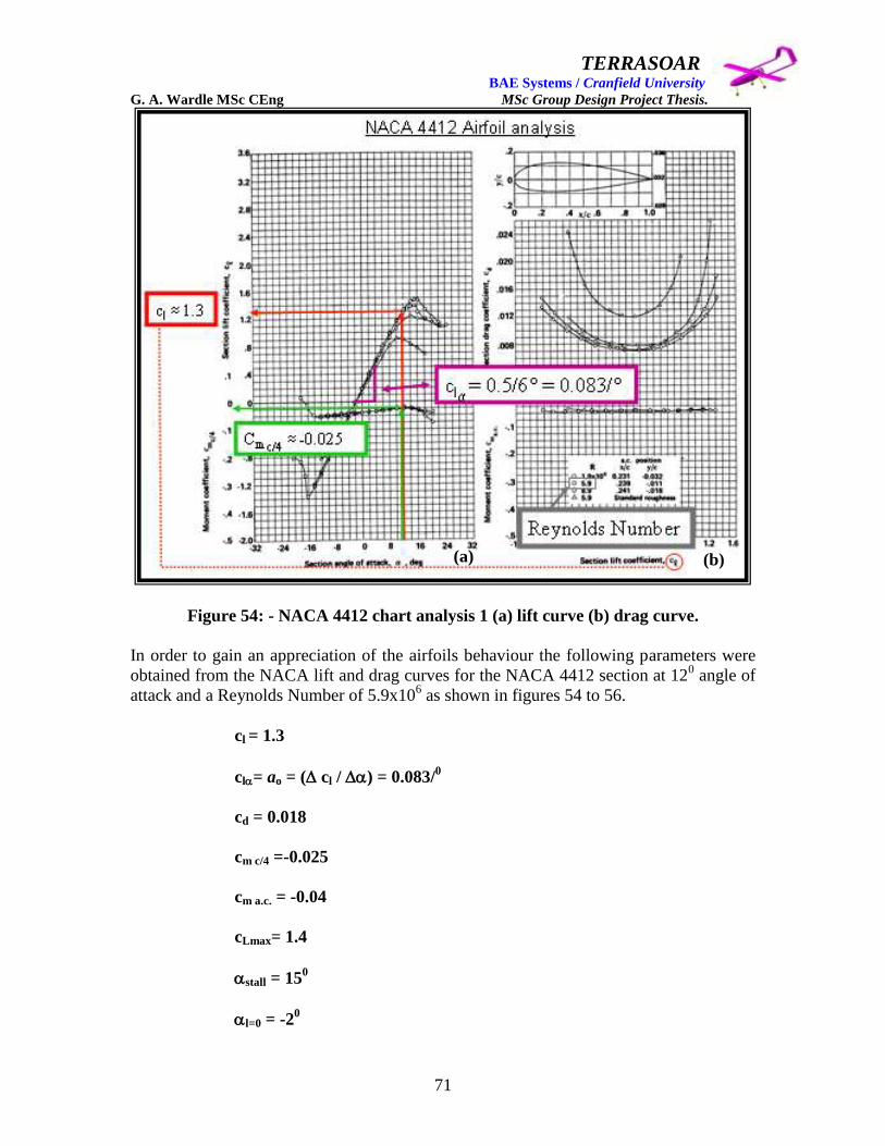
TERRASOAR BAE Systems / Cranfield University G. A. Wardle MSc CEng MSc Group Design Project Thesis.
71
Figure 54: - NACA 4412 chart analysis 1 (a) lift curve (b) drag curve.
In order to gain an appreciation of the airfoils behaviour the following parameters were
obtained from the NACA lift and drag curves for the NACA 4412 section at 120 angle of
attack and a Reynolds Number of 5.9x10⁶ as shown in figures 54 to 56.
cl = 1.3
cl= ao = ( cl / ) = 0.083/0
cd = 0.018
cm c/4 =-0.025
cm a.c. = -0.04
cLmax= 1.4
stall = 150
l=0 = -20
(a) (b)

TERRASOAR BAE Systems / Cranfield University G. A. Wardle MSc CEng MSc Group Design Project Thesis.
72
Figure 55: - NACA charts 4412 analysis 2 (a) lift curve (b) drag curve.
The variations of lift cl, drag cd, and momentum cm coefficients with angle of attack
and Reynolds number Re are shown in the NACA charts as lift and drag curves shown in
figures 54 to 56 (the same chart) which are based on actual experimental data obtained by
NACA in the 1940‟s (note in the majority of aerodynamic literature the lift, drag and
moment coefficients are in lower case when dealing with two-dimensional shapes as in
the case of airfoils).
The variation of lift coefficient with angel of attack is shown chart (a) in figures 54
through 56, note the lift curve of cl versus is linear over the most practical angle of
attack range, this is of great importance and is called the lift slope and is designated ao,
for thin military airfoils, a theoretical value for the lift slope is 2 per radian, or 0.11 per
degree is used in performance analysis (page 62: reference 13). This reportedly also the
case for most experimentally measured lift slopes of conventional airfoils, the lift slope
for NACA 4412 was measured as 0.083/0 from chart (a), which is reasonably close to the
theoretical value. Note from chart (a) at = 0 there is a positive value for the lift
coefficient i.e. cl = 0.1 and the airfoil must be pitched down to a negative angle of attack
denoted by l = 0 (in this case -2
0) for the cl lift coefficient to equal 0.
(a) (b)

TERRASOAR BAE Systems / Cranfield University G. A. Wardle MSc CEng MSc Group Design Project Thesis.
73
Figure 56: - NACA charts 4412 analysis 3 (a) lift curve (b) drag curve.
This negative angle of attack is because NACA 4412 is a positively cambered airfoil, a
symmetrical airfoil would have a l = 0 value equal to 0
0 and an airfoil with negative
camber would have a positive value for l = 0, (negative cambers have not been used in
practical aircraft aerodynamics to date).
At high angles of attack the linearity of the lift curve diminishes due to the diversion of
the lift coefficient as it reaches its maximum value cl max in figures 54(a) through 56(a),
as increases further. The drop in cl is the result of separation of the airflow over the top
surface of the airfoil causing a loss of lift, but over the linear portion of the lift curve the
flow is attached over the majority of the airfoil surface. The lift curve variation of cl with
Re are shown for Reynolds numbers over a range of 1.0 x 10⁶ to 8.9 x 10
6 in figures 54
through 56, and there appears to be very little effect at these high Reynolds numbers
associated with normal size wing chord lengths for normal flight.
(b) (a)

TERRASOAR BAE Systems / Cranfield University G. A. Wardle MSc CEng MSc Group Design Project Thesis.
74
However at the much lower Reynolds numbers associated with model aircraft and many
small UAV‟s (in the order of 100,000) there is a substantial Reynolds number effect on
the lift curve which is reduced below the values shown here, according to reference 15.
However there was insufficient time within this project for the author to explore this
further and a full and detailed treatment of this issue should be given in reference 7.
The variation of momentum coefficient cm is shown to be essentially linear over most of
the practical angles of attack in figures 54(a) through 56(a) demonstrating that for this
airfoil the moment coefficient curve mo = dcm / d is essentially constant over the
practical angles of attack considered. Although the curve is positive for this airfoil this is
not always the case and for some airfoils it can be negative. As with the lift coefficient
the slope becomes non – linear at high angels of attack due to flow separation on the top
surface of the airfoil and also at low angles of attack due to flow separation on the bottom
surface of the airfoil. In common with the lift curve the linear portion of the momentum
curve is essentially independent of the Reynolds number values considered in these
charts.
The variation of cd with the lift coefficient is shown in figures 54(b) through 56(b) and
from these charts it can be seen that for a positively cambered airfoils of the NACA 4412
type the minimum value of the drag coefficient cd min dose not necessarily occur at zero
angle of attack but rather at some finite small angle of attack. This is because at very low
angles of attack for example -20 to +2
0 the drag is the result of friction and pressure drag
over the airfoil surface. At higher angles of attack the drag coefficient rises very steeply
(exponentially) due to flow separation over the airfoil which creates rapidly large
pressure drag values. Also shown in these charts is the effect of Reynolds number on cd
which unlike cl (at the Reynolds number range considered here) is sensitive to Re and is
larger at lower Reynolds number values, also because the Reynolds number influences
the extent and character of the separated flow region cd at high is also influenced by
the Re value considered.
Also shown in figures 54(b) through 56(b) is the variation of the moment coefficient
about the aerodynamic centre cm a.c. which is essentially constant over the range of lift
coefficients and hence the range of angles of attack considered.
Although this airfoil section was considered adequate for initial concept definition and
was carried through to the second stage configuration studies by the author the airfoil
selected for the final flying aircraft was the Wortmann FX 63-137 was intended for use in
applications where compressibility was not a problem which was the case with the
Terrasoar. But although maximum lift coefficients in the order of two were quoted for
this airfoil these were associated with a high zero lift pitching moment in excess of -0.1,
and the very thin reflexed trailing edge of the Wortmann airfoil was to cause difficulties
in structural design and manufacturing requiring some modification, additionally this
section was very sensitive to surface roughness at the scales used on Terrasoar
complicating manufacture still further.

TERRASOAR BAE Systems / Cranfield University G. A. Wardle MSc CEng MSc Group Design Project Thesis.
75
The Wortmann FX63-137 airfoil is fully described in reference 7 including all data
charts, and is shown below in figure 57 for comparison with the NACA 4412 selected for
the concepts only this concludes discussion of the author‟s concept wing configurations.
Figure 57: - WORTMANN FX 63 – 137 Airfoil.
5): - Empennage configuration: - The conventional configuration for the empennage
unit would have been a horizontal fixed tail plane and a fixed vertical fin each being
fitted with a hinged rear flap acting as an elevator for pitch control and a rudder for yaw
control respectively, as shown in figure 58, and in some cases a dorsal fairing is
employed at the base of the fin to arrest the possibility of fin stall. However due to the
decision made above to adopt a pusher propeller / engine configuration for all piston
engine configurations this conventional layout was not possible without limiting the
effectiveness of the control surfaces as airflow drawn in by the propeller would
considerably restrict there movement in response to actuator inputs. Also in the case of
the jet powered configuration three the conventional fin would be in constant jet wash
and be rendered ineffective. These considerations left only two options open to the
author, of which: - one was the twin tail fin replacing the conventional single vertical fin
with a pair of fins located at the extremities of the horizontal tail, although this tends to
have mass (stiffening of the horizontal tails) and aerodynamic interference penalties (due
to fuselage obscuration in sideslip): and the second was the twin boom layout used in
configuration one, with twin fins located on the booms, which incurred a wing mass
penalty, and greater interference drag.

TERRASOAR BAE Systems / Cranfield University G. A. Wardle MSc CEng MSc Group Design Project Thesis.
76
Figure 58: - Aircraft reference axes and corresponding aerodynamic moments.
Taking all of the above into account the author generated the four configurations GW 1
through 4 described above and submitted these for evaluation, as shown in figure 42 and
table 5 the results of which were generated in the author‟s absence due to sickness, by the
M1 module runner up team.
3.2: - Airframe configuration down selection.
The outcome of this initial concept was that only three of the original designs fared well
but these were compared with photographs of current flying UAV‟s which had hundreds
of man hours and millions of dollars spent on them therefore the decision matrix could
not be deemed a reliable indicator of the three original designs merit. The jet options
proposed by the author were always going to be high risk options on grounds of
endurance and in the field maintainability, but in the authors view the piston engine
configurations were worthy of further study and design maturation.
Of these three the authors Configuration 1 was judged to have the least risk associated
with the overall concept, however to reduce risk further for a fixed or retractable tricycle
undercarriage version two low wing configurations were explored by the author with a
reduced drag fuselage cross – section and were configurations 6(A) / (B) and 7
respectively described below. In the final analysis these would be compared with a
modified Intake 5 airframe developed by Mr James Pennington.
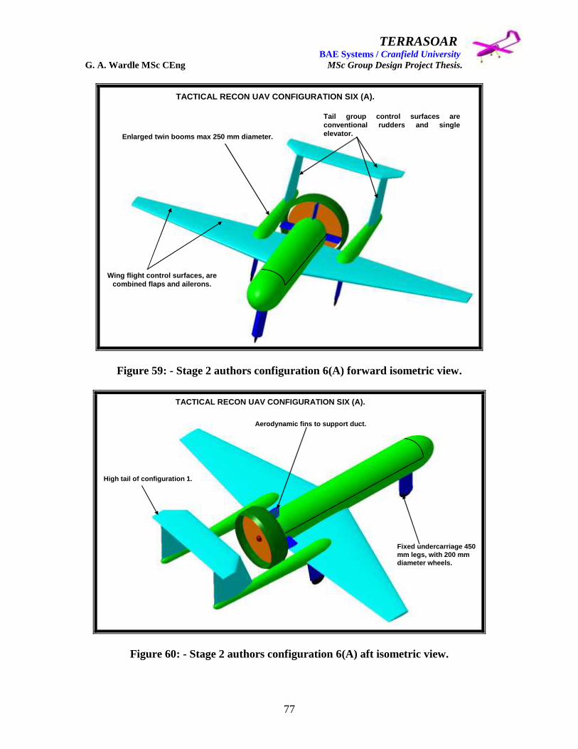
TERRASOAR BAE Systems / Cranfield University G. A. Wardle MSc CEng MSc Group Design Project Thesis.
77
TACTICAL RECON UAV CONFIGURATION SIX (A).
Enlarged twin booms max 250 mm diameter.
Wing flight control surfaces, are
combined flaps and ailerons.
Tail group control surfaces are
conventional rudders and single
elevator.
Figure 59: - Stage 2 authors configuration 6(A) forward isometric view.
TACTICAL RECON UAV CONFIGURATION SIX (A).
Aerodynamic fins to support duct.
High tail of configuration 1.
Fixed undercarriage 450
mm legs, with 200 mm
diameter wheels.
Figure 60: - Stage 2 authors configuration 6(A) aft isometric view.

TERRASOAR BAE Systems / Cranfield University G. A. Wardle MSc CEng MSc Group Design Project Thesis.
78
Figure 61: - Stage 2 authors‟ configuration 6A supporting data.
Configuration 6(A)/(B):- This configuration was offered by the author in a fixed
undercarriage (A) version and a retractable undercarriage (B) version, and with the
exception of the retractable undercarriage feature in all other respects the two
configurations were identical. A tubular fuselage of 400mm diameter with a keel and two
side longerons, four bulkhead frames for:- the engine attachment: fuel tank fire wall:
wing pick-up attachment: and nose wheel attachment: two intermediate frames separating
avionics and payload bay and power modules, was proposed. This fuselage skin would
have two sections a lower integral skin attached to the frames longerons and keel to
distribute the fuselage bending loads, and a top cover which started at the payload bay
frame and ran to the engine bay as shown in figures 59 and 60. The empennage booms
were sized to permit the undercarriage to be retracted into them on the 6(B) version but
due to the heavy landing case and the wing joint being at the boom attachment point the
size was kept common for both 6(A) and (B) versions. The wing was to be a two spar
structural wing (containing rubs rather than a block of foam) with the leading edge spar at
15% chord and the trailing edge spar at 75% chord, with attachment ribs for the ailerons
and flaperons, and fuselage attachment ribs with lugs which would be pinned through
longeron „H‟ extensions and covered by the fuselage / wing blend panels. These wings
would have top and bottom wing skins forming the torsion box broken at the inboard
wing / outboard wing joint, with a „D‟ – nose attached to the leading edge spar and „V‟
trailing edge cover attached to the trailing edge. A propeller FOD ring was also fitted to
prevent foreign object debris impacting on the propeller which could have been thrown
up form a rough field take-off and landing. The wide track robust undercarriage layout
promoted off airfield operations, and although the cylindrical fuselage would have
required avionics repackaging the form is used in many UAV‟s including the new Watch
Keeper Royal Army UAV‟s, but this was considered too radical and configuration 7
studies began.
GENERAL FEATURES OF CONFIGURATION 6(A) NEW BUILD.
Wing span: - 4.0 m Wing area: - 2.764 m2
Root Chord: - 1.0 m Tip Chord: - 300 mm L/E Sweep: - 11 deg O/A Length: - 2.6 m Fuse diameter: - 400 mm Propeller diameter: - 650 mm Tail plane area: - 0.525 m2
Fin area (each one): - 0.307 m2
Main wheel track: - 1.0 m Nose wheel to main wheel: - 1.720 m
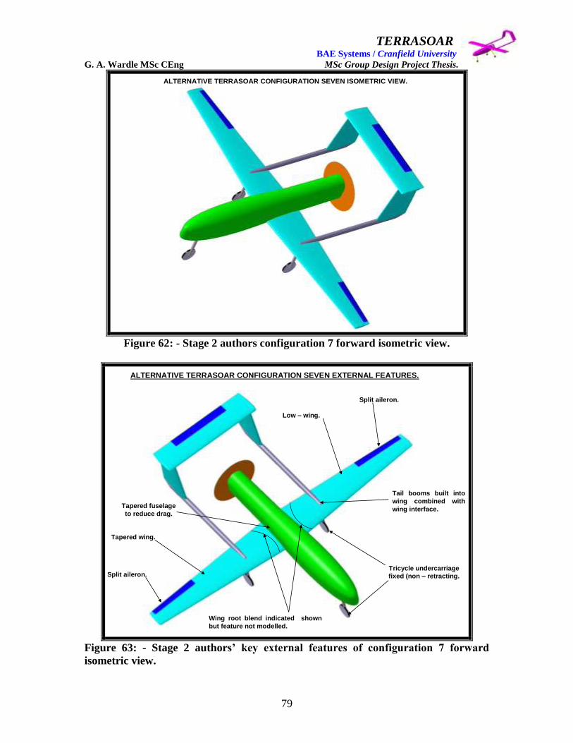
TERRASOAR BAE Systems / Cranfield University G. A. Wardle MSc CEng MSc Group Design Project Thesis.
79
ALTERNATIVE TERRASOAR CONFIGURATION SEVEN ISOMETRIC VIEW.
Figure 62: - Stage 2 authors configuration 7 forward isometric view.
ALTERNATIVE TERRASOAR CONFIGURATION SEVEN EXTERNAL FEATURES.
Tapered wing.
Split aileron.
Low – wing.
Split aileron.
Tricycle undercarriage
fixed (non – retracting.
Tapered fuselage
to reduce drag.
Tail booms built into
wing combined with
wing interface.
Wing root blend indicated shown
but feature not modelled.
Figure 63: - Stage 2 authors‟ key external features of configuration 7 forward
isometric view.

TERRASOAR BAE Systems / Cranfield University G. A. Wardle MSc CEng MSc Group Design Project Thesis.
80
ALTERNATIVE TERRASOAR CONFIGURATION SEVEN EXTERNAL FEATURES.
Tail group control surfaces
are conventional rudders
and single elevator.
Pusher prop with rear mounted
engine with smaller propeller
diameter 800mm.
Thinner tail boom then
configuration 6 to reduce
drag.
Figure 64: - Stage 2 authors‟ key external features of configuration 7 aft isometric
view.
Configuration 7 external features:- This aircraft shown in figures 62 trough 64 was a
lager aircraft than configuration 6, with a wing span of 5m and a length of 3.1m, and a
higher aspect ratio wing of 9.8, compared with 5.8 for configuration 6, but was still of
tapered planform. The undercarriage was fixed for this configuration but retained a wide
track for rough field service use, and empennage boom diameter had dropped to 50mm
reflecting the use of filament wound CFC tube which would be much stronger and stiffer
than the structural boom proposed in configuration 6, although like the former
configuration they formed part of the inboard / outboard wing interface. The empennage
layout was the same basic arrangement as configuration 6 with a single elevator attached
to the horizontal tail, and two rudders attached to the two vertical fins mounted on the
booms, controlling pitch and yaw respectively. Roll was controlled by pairs of ailerons
mounted on each of the outboard wings and driven by independent actuators one for each
aileron, this provided a degree of control surface redundancy and dispensed with the need
for the flaperons proposed for configuration 6. The undercarriage was not faired on this
configuration to reduce weight but required proper sizing, the propeller diameter had also
been increased to 800mm on advice from Mr James Pennington who was responsible for
the propeller sizing activity, and clearance in take-off rotation still required examination.
As with configuration 6 there was a wing / fuselage blend cover which was removable for
wing attachment bolt removal. The fuselage was optimised for a 25kg payload proposed
by BAE SYSTEMS North America, and tapered over the wing to reduce drag.

TERRASOAR BAE Systems / Cranfield University G. A. Wardle MSc CEng MSc Group Design Project Thesis.
81
ALTERNATIVE TERRASOAR CONFIGURATION SEVEN INTERNAL FUSELAGE STRUCTURE.
Payload bay.
XREA avionics bay.
Fuel tank bay.
Transponder and nav bay.
Power modules.
Engine bay.
Wing attach full frames.
Fire wall frames.
Split frames.
Split frame.
Figure 65: - Stage 2 authors‟ key internal layout details of configuration 7 fuselage
aft isometric view.
Configuration 7 fuselage internal features: - The configuration 7 fuselage was to
employ structural skin technology with a two part stiff skin carrying the fuselage bending
loads between frames. These frames would be a nix of horizontally split frames and full
depth frames with the latter being mechanically fastened to the bottom skin but not to the
top skin, and the split frames being fastened to both. The bottom fuselage would have
been fitted with a reinforced belt strip at the waterline interface joint between the top and
bottom skins and the top skin would be mechanically fastened through this strip using
anchor nuts and countersunk bolts. This top skin would be additionally stiffened by the
top half of the split frames which would have been mechanically fastened to it, this would
have enabled the top skin to be removed an one piece during ground handling for battery
charging, payload servicing, or avionics modification. Also of note is the provision for
the XRAY avionics crate although an alternative was under investigation, the customer
had requested this provision as a fall back solution. The nose wheel attaches to the
forward payload bay split frame, and the wing attaches to the three centre fuselage full
frames. Analysis may have shown the stiff skins to be too heavy, so ample provision for a
keel and longerons to be built into the design running under the systems, power, and
avionics trays, as shown in figure 65 above.

TERRASOAR BAE Systems / Cranfield University G. A. Wardle MSc CEng MSc Group Design Project Thesis.
82
ALTERNATIVE TERRASOAR CONFIGURATION SEVEN INTERNAL WING STRUCTURE.
Aileron actuator bays.
Wing box leading edge ‘C’ spar.
Wing box trailing edge ‘C’ spar.
Split aileron.
Bottom wing skin.
Top wing skin.
Wing inboard / outboard joint
and boom interface.
Wing ‘D-nose’ locked by T tie.
Figure 66: - Stage 2 authors‟ key internal layout details of configuration 7 wing
forward isometric view.
Configuration 7 wing internal features: - This configuration also had a structural wing
like that proposed for configuration 6, (containing spars and ribs as apposed to a block of
foam), the wing torsion box had a leading edge „C‟ section spar at 25% chord and a
trailing edge „C‟ section spar at 75% chord with 6 outboard wing ribs and three inboard
wing ribs (wing to fuselages attachment ribs obscured by fuselage), as shown in figure 66
above. The wing to fuselage attachment ribs were to be full chord ribs attaching to the
full depth frames shown in figure 65, by means of six outboard / inboard pins three each
side passing through fork end lugs in the frames, and single tongue lugs on the ribs.
The inboard to outboard wing joint was achieved by the boom effectively hooking over
metal fittings that form slots for the overlapping torsion box spar webs, and the
undercarriage leg being screwed into a metal fitting at the attachment end of the boom.
Although this attachment methodology requires much further investigation the author
considered it as a good starting point.
Separate bays were provided for the aileron actuators bounded by the ribs to which the
ailerons attached to the wing spars, as shown above.

TERRASOAR BAE Systems / Cranfield University G. A. Wardle MSc CEng MSc Group Design Project Thesis.
83
GENERAL FEATURES OF CONFIGURATION 7 NEW BUILD.
Wing span:- 5.0 m
Wing area:- 2.552 m2
Root Chord:- 750 mm
Tip Chord:- 300 mm
L/E Sweep:- 5 deg
O/A Length:- 3.1 m
Fuse diameter max:- 568.744 mm
Propeller diameter:- 800 mm
Tail plane area:- 1.609 m2
Fin area (each one):- 0.402 m2
Boom Length:- 2.54 m
Boom diameter:- 50 mm
Figure 66: - Stage 2 authors‟ configuration 7 supporting data.
Figure 67: - General configuration notes for both configurations 6 and 7.
This concludes the descriptions of configurations 6 and 7 as presented for the final
selection review on the 4th
September 2003.
General configuration notes.
• All configurations had ailerons, rudders, and elevators.
• Both aircraft configurations 6(A) / (B) and 7 had tricycle undercarriage arrangement.
• All three configurations had been sized based on Terrasoar overall dimensions, and had been modified to meet the new mission requirements and need parametric analysis.
• The prop size had been reduced to diameters of 650 mm - 800 mm to reflect the new mission requirements and needed parametric analysis.
•These are all general arrangement CATIA V5 models and were only intended for configuration concept capture and not intended to form the basis of surface models for manufacture.
•Configuration 7 had the same twin boom layout with a different fuse and
a five meter wing span, sized for a 25 kg payload.
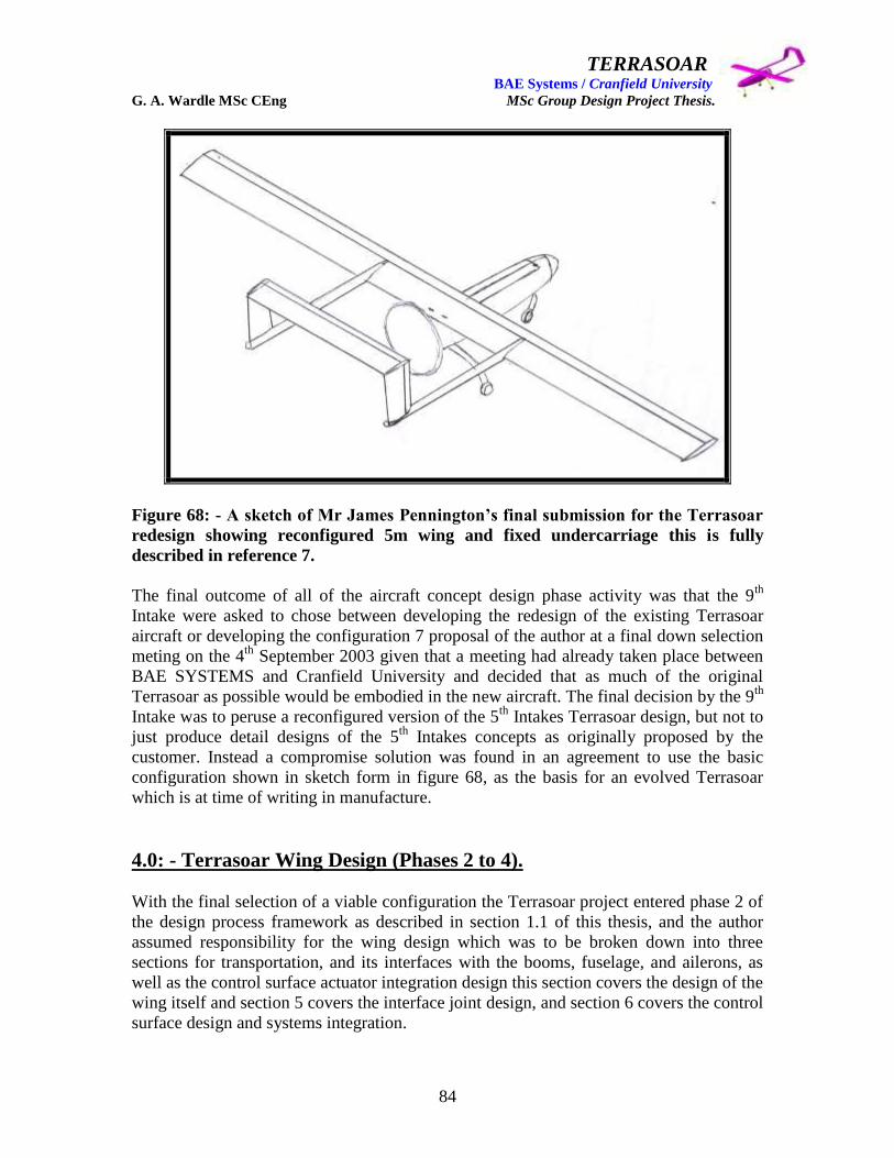
TERRASOAR BAE Systems / Cranfield University G. A. Wardle MSc CEng MSc Group Design Project Thesis.
84
Figure 68: - A sketch of Mr James Pennington‟s final submission for the Terrasoar
redesign showing reconfigured 5m wing and fixed undercarriage this is fully
described in reference 7.
The final outcome of all of the aircraft concept design phase activity was that the 9th
Intake were asked to chose between developing the redesign of the existing Terrasoar
aircraft or developing the configuration 7 proposal of the author at a final down selection
meting on the 4th
September 2003 given that a meeting had already taken place between
BAE SYSTEMS and Cranfield University and decided that as much of the original
Terrasoar as possible would be embodied in the new aircraft. The final decision by the 9th
Intake was to peruse a reconfigured version of the 5th
Intakes Terrasoar design, but not to
just produce detail designs of the 5th
Intakes concepts as originally proposed by the
customer. Instead a compromise solution was found in an agreement to use the basic
configuration shown in sketch form in figure 68, as the basis for an evolved Terrasoar
which is at time of writing in manufacture.
4.0: - Terrasoar Wing Design (Phases 2 to 4).
With the final selection of a viable configuration the Terrasoar project entered phase 2 of
the design process framework as described in section 1.1 of this thesis, and the author
assumed responsibility for the wing design which was to be broken down into three
sections for transportation, and its interfaces with the booms, fuselage, and ailerons, as
well as the control surface actuator integration design this section covers the design of the
wing itself and section 5 covers the interface joint design, and section 6 covers the control
surface design and systems integration.

TERRASOAR BAE Systems / Cranfield University G. A. Wardle MSc CEng MSc Group Design Project Thesis.
85
4.1: - Structural definition for wing design.
The wing configuration selected was rectangular with a taper ratio of ct / cr = 1.0 with
initially with no twist, and the maximum design velocity of the Terrasoar UAV in normal
flight was estimated to be in the region of 85 miles / hour - far below the transonic
regime; and hence there is no aerodynamic requirement for any sweep in the wing. From
reference 13 the minimum induced drag would be produced from with an elliptical
spanwise lift distribution, which implies an elliptical planform shape. However as stated
above the higher production costs associated with a wing with curved leading and trailing
edges in the planform view could not justified in view of the cheaper costs of
manufacturing wings with straight leading and trailing edges. Moreover, by choosing the
correct taper ratio, the elliptical lift distribution can be closely approximated, however as
stated above this has not been considered necessary in the down selected design.
The rectangular wing chosen would have been heavier than a tapered wing of the same
span because as the taper ratio decreases the centroid of the lift distribution (centre of
pressure) moves closer to the root of the wing. In turn, the moment arm from the root to
the centre of pressure decreases, and the bending moment at the root decreases, and the
lift stays the same. As a result, the wing structure can be made lighter. This trend is a
benefit obtained from using a small taper ratio, and as will be seen in the next section this
was selected by the 5th
Intake.
However wings with low taper ratios (pointed wing tips) exhibit undesirable flow
separation and stall behaviour, because as the taper ratio decreases the region where flow
separation first develops moves out towards the tip and as a result aileron control is
adversely affected.
The rectangular wing of taper ratio = 1.0 selected here would develop flow separation
first in the root region. This location for flow separation has two advantages: - (1) If a
tractor configuration had been selected then the separated, turbulent flow trails
downstream from the root region causing buffeting as it flows over the horizontal tail,
thus serving as a dynamic stall warning to the controller, however with the twin boom
layout this indicator was lost. (2) The wing - tip region still has attached flow, and
because the ailerons (for lateral control) are located in this region, the pilot still has full
aileron control.
The conceptual design of aircraft structure required assessment of where major structural
members would be positioned within the aircraft. Careful positioning of structural
members could save significant structural weight and can greatly simplify manufacturing,
operation, and maintenance of the aircraft.
This thesis deals with the wing alone and the following overview covers the wing
structural layout for a conventional aircraft or large scale flying model which the author
intended to employ in the design of the Terrasoar wing.
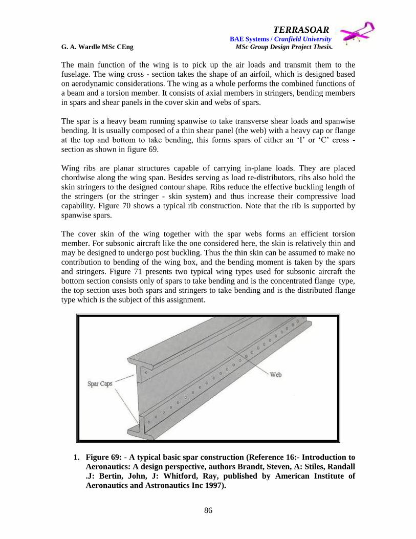
TERRASOAR BAE Systems / Cranfield University G. A. Wardle MSc CEng MSc Group Design Project Thesis.
86
The main function of the wing is to pick up the air loads and transmit them to the
fuselage. The wing cross - section takes the shape of an airfoil, which is designed based
on aerodynamic considerations. The wing as a whole performs the combined functions of
a beam and a torsion member. It consists of axial members in stringers, bending members
in spars and shear panels in the cover skin and webs of spars.
The spar is a heavy beam running spanwise to take transverse shear loads and spanwise
bending. It is usually composed of a thin shear panel (the web) with a heavy cap or flange
at the top and bottom to take bending, this forms spars of either an „I‟ or „C‟ cross -
section as shown in figure 69.
Wing ribs are planar structures capable of carrying in-plane loads. They are placed
chordwise along the wing span. Besides serving as load re-distributors, ribs also hold the
skin stringers to the designed contour shape. Ribs reduce the effective buckling length of
the stringers (or the stringer - skin system) and thus increase their compressive load
capability. Figure 70 shows a typical rib construction. Note that the rib is supported by
spanwise spars.
The cover skin of the wing together with the spar webs forms an efficient torsion
member. For subsonic aircraft like the one considered here, the skin is relatively thin and
may be designed to undergo post buckling. Thus the thin skin can be assumed to make no
contribution to bending of the wing box, and the bending moment is taken by the spars
and stringers. Figure 71 presents two typical wing types used for subsonic aircraft the
bottom section consists only of spars to take bending and is the concentrated flange type,
the top section uses both spars and stringers to take bending and is the distributed flange
type which is the subject of this assignment.
1. Figure 69: - A typical basic spar construction (Reference 16:- Introduction to
Aeronautics: A design perspective, authors Brandt, Steven, A: Stiles, Randall
.J: Bertin, John, J: Whitford, Ray, published by American Institute of
Aeronautics and Astronautics Inc 1997).
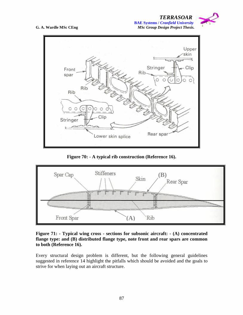
TERRASOAR BAE Systems / Cranfield University G. A. Wardle MSc CEng MSc Group Design Project Thesis.
87
Figure 70: - A typical rib construction (Reference 16).
Figure 71: - Typical wing cross - sections for subsonic aircraft: - (A) concentrated
flange type: and (B) distributed flange type, note front and rear spars are common
to both (Reference 16).
Every structural design problem is different, but the following general guidelines
suggested in reference 14 highlight the pitfalls which should be avoided and the goals to
strive for when laying out an aircraft structure.
(A)
(B)
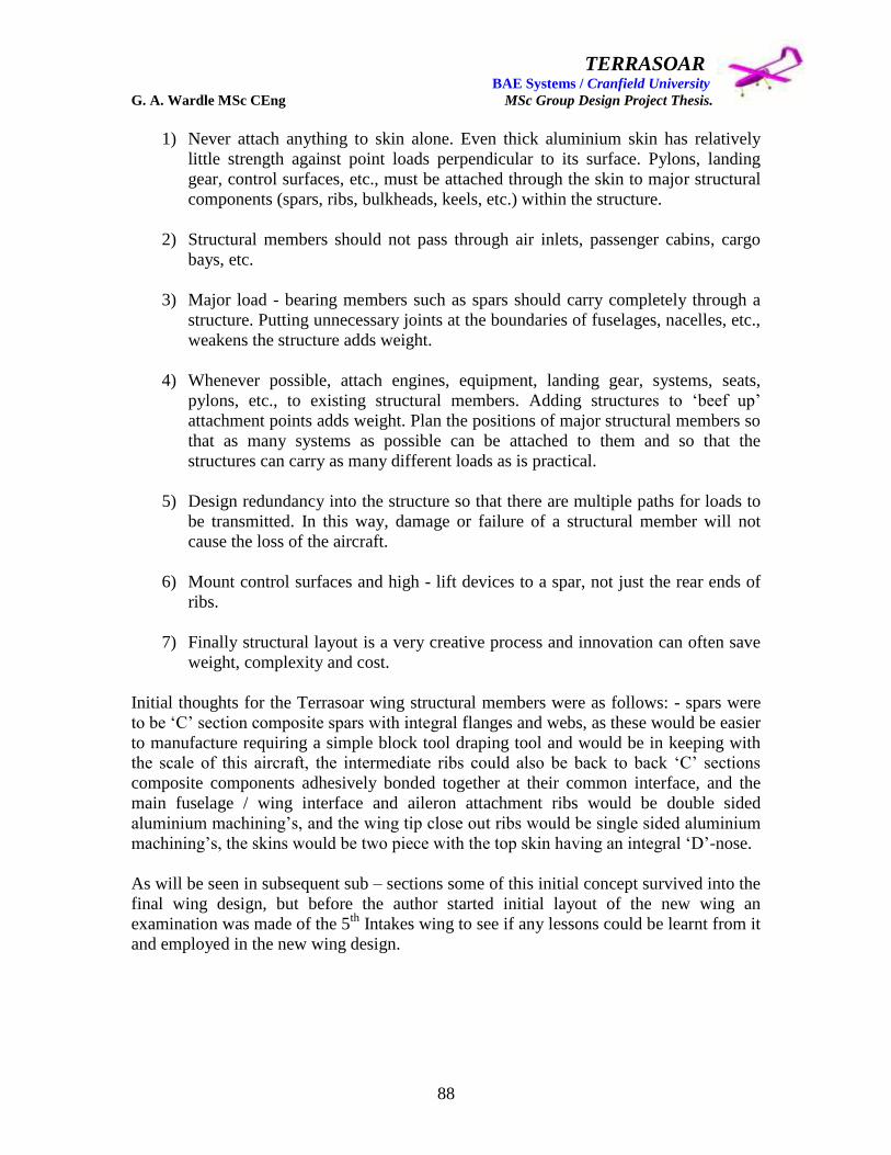
TERRASOAR BAE Systems / Cranfield University G. A. Wardle MSc CEng MSc Group Design Project Thesis.
88
1) Never attach anything to skin alone. Even thick aluminium skin has relatively
little strength against point loads perpendicular to its surface. Pylons, landing
gear, control surfaces, etc., must be attached through the skin to major structural
components (spars, ribs, bulkheads, keels, etc.) within the structure.
2) Structural members should not pass through air inlets, passenger cabins, cargo
bays, etc.
3) Major load - bearing members such as spars should carry completely through a
structure. Putting unnecessary joints at the boundaries of fuselages, nacelles, etc.,
weakens the structure adds weight.
4) Whenever possible, attach engines, equipment, landing gear, systems, seats,
pylons, etc., to existing structural members. Adding structures to „beef up‟
attachment points adds weight. Plan the positions of major structural members so
that as many systems as possible can be attached to them and so that the
structures can carry as many different loads as is practical.
5) Design redundancy into the structure so that there are multiple paths for loads to
be transmitted. In this way, damage or failure of a structural member will not
cause the loss of the aircraft.
6) Mount control surfaces and high - lift devices to a spar, not just the rear ends of
ribs.
7) Finally structural layout is a very creative process and innovation can often save
weight, complexity and cost.
Initial thoughts for the Terrasoar wing structural members were as follows: - spars were
to be „C‟ section composite spars with integral flanges and webs, as these would be easier
to manufacture requiring a simple block tool draping tool and would be in keeping with
the scale of this aircraft, the intermediate ribs could also be back to back „C‟ sections
composite components adhesively bonded together at their common interface, and the
main fuselage / wing interface and aileron attachment ribs would be double sided
aluminium machining‟s, and the wing tip close out ribs would be single sided aluminium
machining‟s, the skins would be two piece with the top skin having an integral „D‟-nose.
As will be seen in subsequent sub – sections some of this initial concept survived into the
final wing design, but before the author started initial layout of the new wing an
examination was made of the 5th
Intakes wing to see if any lessons could be learnt from it
and employed in the new wing design.

TERRASOAR BAE Systems / Cranfield University G. A. Wardle MSc CEng MSc Group Design Project Thesis.
89
4.2: - Review of the 5th
Intakes wing design.
The general configurations the fixed aerodynamic surfaces are shown in figures 72
through 77 from reference 3 and structural layout data from Holmes Graham MSc GDP
Thesis (not submitted): and the CATIA models of the 5th
Intake were used for this
review.
Figure 72: - Major fixed aerodynamic surface airfoil selection (reference 3).
Figure 73: - Wing configuration showing dihedral on outboard panels (reference 3).

TERRASOAR BAE Systems / Cranfield University G. A. Wardle MSc CEng MSc Group Design Project Thesis.
90
Figure 74: - Aerodynamic twist built into the wing panels (reference 3).
Figure 75: - Major fixed aerodynamic surfaces (reference 3).
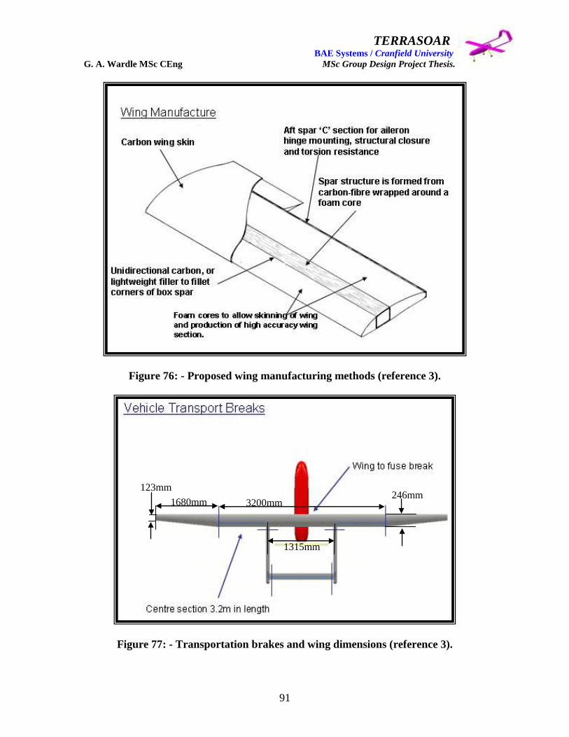
TERRASOAR BAE Systems / Cranfield University G. A. Wardle MSc CEng MSc Group Design Project Thesis.
91
Figure 76: - Proposed wing manufacturing methods (reference 3).
Figure 77: - Transportation brakes and wing dimensions (reference 3).
1680mm 3200mm
1315mm
246mm 123mm

TERRASOAR BAE Systems / Cranfield University G. A. Wardle MSc CEng MSc Group Design Project Thesis.
92
From the aerodynamic analysis and propeller diameter analysis undertaken and captured
in reference 7 for the alternative Terrasoar (which will from here on be called
Terrasoar New Build 1) the 5th
Intake wing planform and physical dimensions shown in
figures 72 through 77 were judge as incompatible with the revised mission requirements
covered in section 2 of this thesis. Indeed by the end of preliminary phase 2 design
studies for Terrasoar New Build 1 the wing span had been reduced from the 5m span of
the phase 1 configuration shown in figure 68 to 3.620m, which remained constant for the
rest of the project, this compared with the 5th
Intakes 6.560m, also the chord was
increased to a constant 0.362m over the entire span of the wing compared to the 5th
Intakes 0.246m centre panel chord, and 0.123m tip chord. These dimension changes
combined with the adoption of a conventional recovery on fixed undercarriage enabled
the ailerons and their actuators to be moved into the outboard wing panels to provide a
greater aerodynamic roll moment giving these control surfaces more authority.
The aerofoil selected was the Wortmann FX 63-137 because of its high potential lift
coefficient and experience gained with this airfoil section within Cranfield University on
UAV‟s of a similar scale to Terrasoar New Build 1, effectively nullifying the 5th
Intakes
airfoil selection of DAE 11 as shown in figure 72. The reason for the dihedral in the
outboard wing panels of the original Terrasoar design shown in figure 73 was not clear
because as stated above in section 3 this feature is usually associated with low wing
configurations to aid roll stability, high wing configurations are inherently roll stable and
although not found with Terrasoar New Build 1 often require a slight anhedral to over
come a high degree of roll stability, the author found it difficult to see the benefit of the
figure 73 configuration given the comparatively small roll moment arm and physical size
of the 5th
Intakes ailerons.
Given the 50 dihedral of the outboard wing panels the geometric twist of -2.5
0 to create
some degree of „wash out‟ was probably necessary to control the lift distribution and
hence the boundary layer separation and stall characteristics, but was initially judge
unnecessary on Terrasoar New Build 1, during design maturation described below a -50
geometric twist was incorporated in the outboard wing panels for the same reason.
Initially a similar separated inboard to outboard wing joint and boom to wing joint
philosophy to that of the 5th
Intake shown in figure 75 was considered for Terrasoar New
Build 1, because initially the combined bending moment of the wing and the twisting
moment of the booms was considered too high for a single joint but during maturation
described below a single joint was developed to handle both interfaces in one assembly.
The wing construction shown in figure 76 was not considered adequate for the Terrasoar
New Build 1 wing by the author and when the detail drawings (reference 3 sub ref: -
Appendix 4: Richard Halliburton: GDP MSc Thesis Terrasoar HALE UAV Wing and
Tail Boom Design: Cranfield University 2001) were examined the design philosophy
although possibly adequate for the 5th
Intake wing was not appropriate larger wing
developed for the Terrasoar New Build 1.

TERRASOAR BAE Systems / Cranfield University G. A. Wardle MSc CEng MSc Group Design Project Thesis.
93
Because of the changes in wing span, propeller diameter, and boom separation the
location of the 5th
Intakes transportation joints shown in figure 77 were not appropriate
for the wing of Terrasoar New Build 1.
The final conclusion of this review of the work of Mr Richard Halliburton the wing and
tail boom designer of the 5th
Intake, was that although a good degree of design maturity
was presented in his thesis, design drawings and PDR presentation unfortunately non of
this could be carried across to the Terrasoar New Build 1 wing design.
4.3 (A) Status wing layout and structural definition for PDR.
From aerodynamic analysis covered in reference 7 the PDR (A) Status wing design was a
3.620mm straight wing, with an aspect ratio of 10, the transportation requirements being
met by breaking the wing into three sections as shown in figure 78, with load transfer
accomplished through forward and aft spars at 15% chord and 65% chord respectively.
The wing airfoil co-ordinates were sourced from the University of Illinois Airfoil Data
Site: - http://www.aae.uiuc.edu/m-selig/ads/coord/fx63137.dat the recommended data
site.
Figure 78: - (A) Status wing general arrangement model at PDR exit.
The outstanding issues from PDR were as follows: - mate joint philosophy, centre to
outboard wing sections, and centre section to fuselage: the manufacturing methods for the
wing and the rest of the airframe: aileron size: FCS integration: navigation light
integration: structural sizing.

TERRASOAR BAE Systems / Cranfield University G. A. Wardle MSc CEng MSc Group Design Project Thesis.
94
The first choice for the wing structure following the work of intake 5 was the use of a
foam core for the wing sections to which the spars were to be bonded, this would have
imparted torsional rigidity under aerodynamic and manoeuvre loads, and ground
handling, which would be covered by a glass fibre skin for aerodynamic cleanness of the
wing outer mould lines, and to seal the foam from moisture ingress. Ribs were required
for attachment of wing to the fuselage and where the cavities for the aileron control
actuators were located (areas with on foam supporting them), as well as for attachment of
the booms for the empennage, and the structural key features of this wing are shown in
figure 79 below.
Figure 79: - (A) Status internal structural arrangement at PDR exit.
The attachment to the fuselage was to be achieved by two ribs with integral fore and aft
lugs aligned with the fwd and aft spars as detailed in section four, these lugs located into
the channel section and bolted through as descried in section five.
The outboard wing structure is shown some detail below in figure 80 and all of these
initial models were produced as CATIA V5 part concept models of CATIA V4 models
which did not permit making individual components transparent, and for further detail of
the models generated at PDR the reader is referred to the models CATIA V4 held by both
Cranfield University and BAE SYSTEMS New Business Samlesbury.

TERRASOAR BAE Systems / Cranfield University G. A. Wardle MSc CEng MSc Group Design Project Thesis.
95
Figure 80: - (A) Status outboard wing internal structural arrangement at PDR exit.
The central wing section structural layout is shown below in figure 81 illustrating the
location of the fuselage attachment and wing mate joint ribs.
Figure 81: - (A) Status centre wing internal structural arrangement at PDR exit.

TERRASOAR BAE Systems / Cranfield University G. A. Wardle MSc CEng MSc Group Design Project Thesis.
96
The interface joint between the centre wing and the outboard wing sections was to be
achieved by either a tong and groove joint or a pin and lug system both of which are
detailed in section five of this thesis, and the proposed rib arrangement drawing is shown
below in figure 82.
Figure 82: - (A) Status Wing / fuselage interface attachment rib at PDR exit.
4.4 (A) Status wing layout and structural definition post PDR maturation.
Maturation of the PDR structural concept continued but the resulting wing was repeatedly
evaluated as over the parametric weight target, using foam core material that wound not
degrade making the aircraft un airworthy in a year or two after first flight. In the Design
Week of 07 – to – 11 June 2004 (during this week visits were made to a number of
manufacturing facilities to assess their ability to produce the airframe within the
Terrasoar budget and time scale), on a visit to Slingsby Aviation on 08/06/2004 (by
Manufacturing Engineering / Chief Engineer / Airframe Lead (Myself) and
Aerodynamics Lead / Finance Lead) the design and manufacturing teams were
introduced to a new light weight tough / high strength / flexible / long life foam core
material which could be shaped in complex curvature and cured at lower temperatures
thus not requiring an autoclave.
TERRASOAR BAE Systems / Cranfield University G. A. Wardle MSc CEng MSc Group Design Project Thesis.
97
This material in thin sheet form had been used in sandwich skin construction with two
layers of glass pre preg each side to form wings and fuselage structures unsupported by
ribs or frames, of Classified Military UAV‟s, undertaking much demanding missions than
the Terrasoar aircraft, as well as in manned light combat training aircraft.
The Slingsby approach offered a considerable opportunity for weight reduction for the
wing / fuselage / and empennage major build components of the airframe, although the
costs of manufacturing at Slingsby was considered to be beyond the Terrasoar budget.
Therefore upon our return from this assessment visit Manufacturing was tasked by
Airframe to research the possibility of sourcing this material or similar with mechanical
properties data sheets, within BAE Systems, and to assess the viability of an in house
build of the vehicle. Airframe took the action of developing a post PDR (A) Status level
design study employing this build philosophy and to supply all design and materials data
to Stress Engineering. This was the most constructive outcome of the Design Week.
One of the most unfortunate outcomes of the design week was the insistence by Peter
Hamilton that the wing joint philosophy be changed, to his design, this was later to be
formally challenged by Senior BAE Systems stress engineers and found woefully
inadequate, and is addressed in section five.
During the post PDR (A) Status design study the presentation of which on the 17 / 11 /
200 is attached as Appendices 1, the following decisions were made by the author in the
role of the wing designer, in liaison with: - fuselage design, fuel team, flight control
systems, manufacturing and aerodynamics: -
1. Reduce landing speed and aid rotation by imparting a downward twist in the
outboard wing resulting twist in the outboard wing sections between 00 at the
inboard / outboard joint increasing to 20 at the outboard wing leading edge tips.
2. The wing would be raised on the fuselage to lie across the top of the fuselage box
and the fuselage / attachment should be integral to the wing, this provided a
substantial increase in the fuel tank volume if required.
3. The two spar structure would be retained as per PDR which is the only continuous
load path through the wing, and provide load paths and attachment points for the
ailerons.
4. The empennage booms would be attached inboard of the outboard wing section
mate joints and attached through retained inserts in the fwd and aft spars covered
in section four.
5. The four aileron layout would be retained from PDR, each with an individual
actuator this provided duplex redundancy in the aileron system, as a critical flight
safety case, actuator bay access cut outs would be made in the top outboard wing
skins and covered by removable panels.

TERRASOAR BAE Systems / Cranfield University G. A. Wardle MSc CEng MSc Group Design Project Thesis.
98
6. The ailerons would be attached to the rear spar with pairs of discrete lugs as the
wing twist made the original piano hinge arrangement of PDR impractical, also
the author personally preferred discrete lugs as the piano hinges are prone to
jamming as the wing bends in flight. These would be covered by rubber seals.
7. The spars would be made of the same foam sandwich construction as the wing
and fuselage skins, and would be of C - section. These spars would then be
adhesively bonded to the wing skins and additionally secured with countersunk
insurance fasteners into internally mounted nut plates for the top skin and anchor
nuts for the bottom skin. The sub structure would be assembled in basic jigs prior
to skin attachment, and the skins would be two part top and bottom skins with an
integral leading edge as part of the top skin panels, landing on the bottom of the
leading edge spar.
8. Navigation lights would be fitted in the outboard wing section leading edges.
9. The wing tip ribs would be machined aluminium details.
10. Ribs of the same construction as the wings would be used to strengthen aileron
actuator bays by local stiffening, and form a landing for the access panels. Ribs
would also be used as torsion close outs for the three wing sections.
The resulting these studies design were presented at GDP review of the 17 / 11 / 04 and
the detailed presentation was included as Appendices 1 in the GDP Interim report, and
the external configuration is shown below as figure 83, with the internal structure shown
below as figure 84 for reference, as well as the common wing skin and spar construction,
shown for the outboard wing in figures 85 and 86.
At the close of Phase 1 the Airframe design team still lacked any stress data on which to
produce reliably sized detailed parts and material data was being obtained. For design
graphical representation a total sandwich thickness of 4mm was considered realistic.
Following the GDP meeting of the 17 / 11 / 2004 as Airframe Lead the author chaired an
internal design review of the post PDR (A) Status design study wing design with the
Aerodynamics Lead and the Fuselage Design / Systems integration Lead, this covered the
design issues raised in the minutes of the formal GDP meeting namely: -
1. The clip attachment to the fuselage of the wing:
2. The attachment methods for the outboard wing sections:
3. The attachment methods for the empennage booms to the wing:
4. Weight reduction of the airframe in its current non stressed state:
5. No issues were raised with the material or basic structural layout of the wing:

TERRASOAR BAE Systems / Cranfield University G. A. Wardle MSc CEng MSc Group Design Project Thesis.
99
Figure 83: - The Post PDR (A) Status design study exit wing, external configuration.
Figure 84: - The Post PDR (A) Status design study exit wing, internal configuration.

TERRASOAR BAE Systems / Cranfield University G. A. Wardle MSc CEng MSc Group Design Project Thesis.
100
Figure 85: - The Post PDR (A) Status design study 0utboard wing, and external skin
configuration detail.
Figure 86: - The Post PDR (A) Status design study 0utboard wing and internal
structure spar configuration detail, common to all spars inboard and outboard.

TERRASOAR BAE Systems / Cranfield University G. A. Wardle MSc CEng MSc Group Design Project Thesis.
101
4.5: - (B) Status wing layout and structural definition for CDR.
To address the issues raised from the Post PDR (A) Status wing design study the
Aerodynamics Lead suggested a wide rectangular single spar structure would eliminate
the need for the additional ribs, but the author cautioned that a weight trade study would
be required when initial sizing data was available as this spar would have a greater
weight than two modest C – section spars, and would require a reinforced lap joint, as the
spar would be wrapped around a male mould tool. Stress Engineering was been actioned
to study this option, with no result.
Additionally weight reduction could be achieved by adopting a common interface joint
for both the outboard wing sections and the empennage booms although this had been
examined before with a common rib, a fresh study was required as the method of wing
construction had radically changed over the primitive solid foam block method favoured
by Cranfield University representatives and intake 5.
The wing / fuselage attachment philosophy was wrong and required urgent review, as
well as the fuel requirements, as parametric analysis undertaken to that date appeared to
be very conservative, and the Airframe team still had no test data of any kind to support
the Post PDR (A) Status design study fuel tank volume, subsequent testing covered in
reference 8 supported the view of the Airframe team that the initial figures were over
conservative, therefore the decision made to lower the wing back into the fuselage was
correct. The suggestion was made that the wing could be attached to the engine fire wall
and the forward fuel tank frame by two continuous sleeved bolts running forward to aft,
through the spar, and the Aerodynamics Lead and Fuselage Design Lead were charged
with investigating this.
Airframe Design was charged with producing models to reflect the outcomes of this
meeting, and this resulted in the Interim Maturation concept.
The author was on a Cranfield Module S02 and had an extensive F-35B Phase 1 exit /
Phase 2 entry Vertical Tail Customer Presentation / Design Review commitments
increasing an already full F-35 workload, and could offer advice but not design time to
this modelling effort, and this role fell to James Pennington the Aerodynamics Lead, who
was given a two week design window by his IPT Lead namely Eurofighter Typhoon.
Following the authors return from the Christmas holiday the author instigated an “ALL
HAND‟S” Airframe Review meeting on the 7th
January 2005, minutes of which were
submitted as Appendices 4 of the GDP interim report. The complete airframe was studied
at this meeting. No problems with the wing design were foreseen at this meeting though a
discussion of the use of the inboard ailerons as flaperons with FCS Lead / Wing Design
Lead / and Aerodynamics Lead (from whom the request came) to decrease the landing
speed and aid rotation, resulted in an initial enlargement of these surfaces. This Interim
Maturation design study wing layout and internal structural designs shown in figures 87
and 88 for reference.
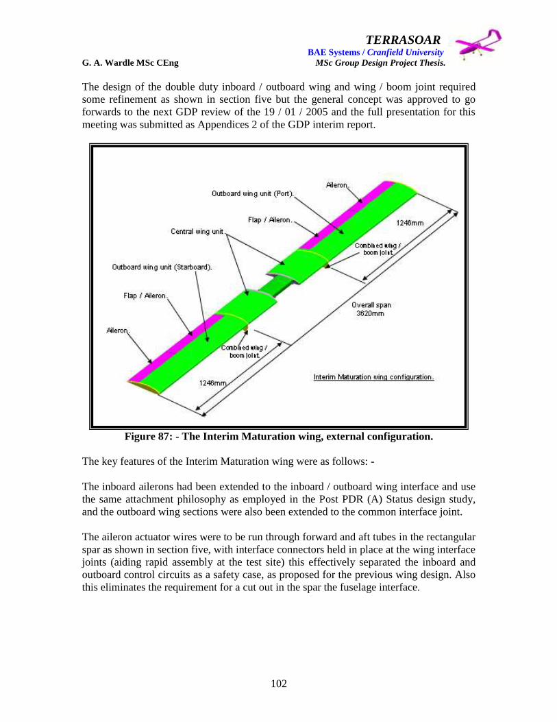
TERRASOAR BAE Systems / Cranfield University G. A. Wardle MSc CEng MSc Group Design Project Thesis.
102
The design of the double duty inboard / outboard wing and wing / boom joint required
some refinement as shown in section five but the general concept was approved to go
forwards to the next GDP review of the 19 / 01 / 2005 and the full presentation for this
meeting was submitted as Appendices 2 of the GDP interim report.
Figure 87: - The Interim Maturation wing, external configuration.
The key features of the Interim Maturation wing were as follows: -
The inboard ailerons had been extended to the inboard / outboard wing interface and use
the same attachment philosophy as employed in the Post PDR (A) Status design study,
and the outboard wing sections were also been extended to the common interface joint.
The aileron actuator wires were to be run through forward and aft tubes in the rectangular
spar as shown in section five, with interface connectors held in place at the wing interface
joints (aiding rapid assembly at the test site) this effectively separated the inboard and
outboard control circuits as a safety case, as proposed for the previous wing design. Also
this eliminates the requirement for a cut out in the spar the fuselage interface.
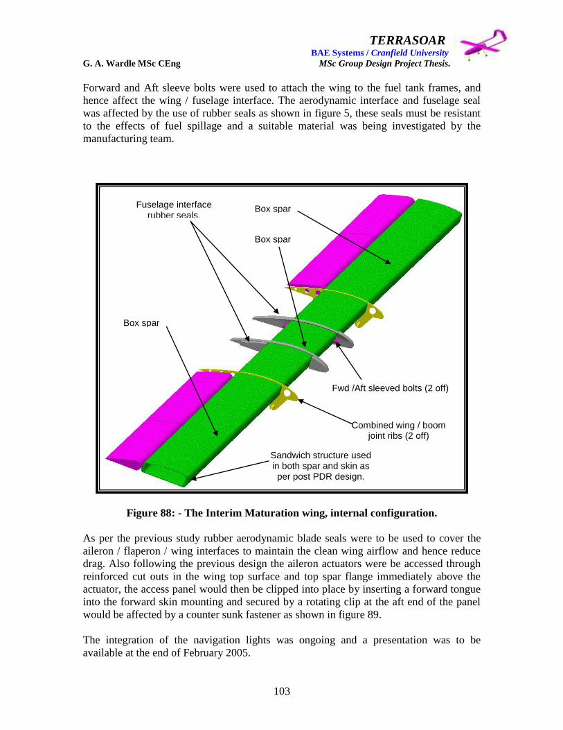
TERRASOAR BAE Systems / Cranfield University G. A. Wardle MSc CEng MSc Group Design Project Thesis.
103
Forward and Aft sleeve bolts were used to attach the wing to the fuel tank frames, and
hence affect the wing / fuselage interface. The aerodynamic interface and fuselage seal
was affected by the use of rubber seals as shown in figure 5, these seals must be resistant
to the effects of fuel spillage and a suitable material was being investigated by the
manufacturing team.
Figure 88: - The Interim Maturation wing, internal configuration.
As per the previous study rubber aerodynamic blade seals were to be used to cover the
aileron / flaperon / wing interfaces to maintain the clean wing airflow and hence reduce
drag. Also following the previous design the aileron actuators were be accessed through
reinforced cut outs in the wing top surface and top spar flange immediately above the
actuator, the access panel would then be clipped into place by inserting a forward tongue
into the forward skin mounting and secured by a rotating clip at the aft end of the panel
would be affected by a counter sunk fastener as shown in figure 89.
The integration of the navigation lights was ongoing and a presentation was to be
available at the end of February 2005.
Box spar
Box spar
Box spar
Combined wing / boom joint ribs (2 off)
Fuselage interface rubber seals.
Sandwich structure used in both spar and skin as per post PDR design.
Fwd /Aft sleeved bolts (2 off)
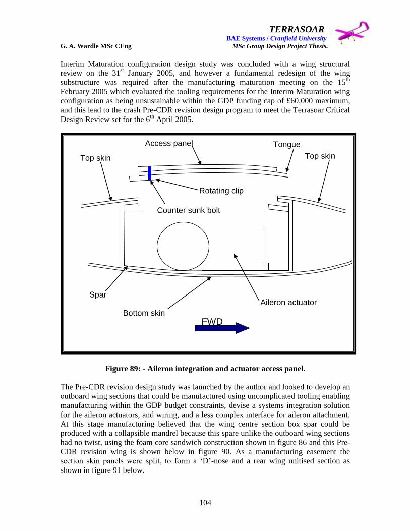
TERRASOAR BAE Systems / Cranfield University G. A. Wardle MSc CEng MSc Group Design Project Thesis.
104
Interim Maturation configuration design study was concluded with a wing structural
review on the 31st January 2005, and however a fundamental redesign of the wing
substructure was required after the manufacturing maturation meeting on the 15th
February 2005 which evaluated the tooling requirements for the Interim Maturation wing
configuration as being unsustainable within the GDP funding cap of £60,000 maximum,
and this lead to the crash Pre-CDR revision design program to meet the Terrasoar Critical
Design Review set for the 6th
April 2005.
Figure 89: - Aileron integration and actuator access panel.
The Pre-CDR revision design study was launched by the author and looked to develop an
outboard wing sections that could be manufactured using uncomplicated tooling enabling
manufacturing within the GDP budget constraints, devise a systems integration solution
for the aileron actuators, and wiring, and a less complex interface for aileron attachment.
At this stage manufacturing believed that the wing centre section box spar could be
produced with a collapsible mandrel because this spare unlike the outboard wing sections
had no twist, using the foam core sandwich construction shown in figure 86 and this Pre-
CDR revision wing is shown below in figure 90. As a manufacturing easement the
section skin panels were split, to form a „D‟-nose and a rear wing unitised section as
shown in figure 91 below.
Top skin Top skin
Aileron actuator
Tongue
Rotating clip
Access panel
Spar
Bottom skin
Counter sunk bolt
FWD

TERRASOAR BAE Systems / Cranfield University G. A. Wardle MSc CEng MSc Group Design Project Thesis.
105
Figure 90: - (B) Status Pre CDR Revision study wing, external configuration.
Figure 91: - (B) Status Pre CDR Revision study wing, internal configuration.

TERRASOAR BAE Systems / Cranfield University G. A. Wardle MSc CEng MSc Group Design Project Thesis.
106
Figure 92: - (B) Status Pre CDR Revision outboard wing, external configuration.
Figure 93: - (B) Status Pre CDR Revision outboard wing, internal configuration.

TERRASOAR BAE Systems / Cranfield University G. A. Wardle MSc CEng MSc Group Design Project Thesis.
107
Figures 91 through 94 show the authors redesign of the outboard wing sections in which
the lessons learnt from both the PDR wing and Post PDR (A) Status design study were
applied.
The wing spar reverted back to separate „C‟-section forward and rear spars which had the
same consolidated sandwich structural construction as shown in figure 86 above,
consisting of two glass cloth plies (each ply being 0.25mm thick) each side (4 plies in all)
of an Alcan Airex R63.80 foam sheet (3mm thick), to give a total spar thickness of 4mm,
for both web and flanges.
These spares were adhesively bonded with flanges inward to a Styrofoam core housing
the actuator mounting plate this core had been machined to the Wortmann FX63-137
airfoil section, and the outboard interface joint, and tip rib. The Styrofoam „D‟-nose was
then adhesively bonded to external face of the front spar web, and the trailing edge
Styrofoam section with the aileron spigot and ailerons was then bonded to the rear spar
external face web, and all interface gaps would be filled with standard aircraft filler. The
resulting structure is shown in figure 93 above.
Finally a 2 ply skin was wrapped over the resulting structure and adhesively bonded to it
under vacuum bag pressure, which would give the skin a bagged finish which at this time
was deemed aerodynamically acceptable, and is shown in figure 92 above.
Figure 94: - (B) Status Pre CDR Revision outboard wing, aileron integration.

TERRASOAR BAE Systems / Cranfield University G. A. Wardle MSc CEng MSc Group Design Project Thesis.
108
Shown in figures 92 and 94 are the changes made to reduce the complexity of the wing /
aileron interface, the multiple hinge approach was dropped by the author in favour of a
continuous steel spigot covered with a plastic sleeve, which was mounted in a potted
insert in the trailing edge foam and ran to a location cup machined into the tip rib, prior to
fitting the ailerons were slipped onto the spigot (each aileron detailed in section 6 having
a hole through its foam core) and then the assembly was adhesively bonded into place as
explained above.
Figure 94 also shows the method selected by the author to mount the aileron actuators as
a combined unit on a single aluminium single side minimum thickness machined plate
each actuator being screwed into spacer blocks prior to mounting on the aluminium plate
securing brackets as detailed in section 6 of this thesis. The physical dimensions for the
ailerons being supplied by Mr James Pennington and Miss Rachel Cunliffe, based on
there detailed analysis which is reported in references 7 and 10. The cover plate for
access to the aileron actuators was intended to land on a picture frame but this had not
been modelled by CDR, and as explained below this was later abandoned in favour of the
cover landing directly on to the spars which were given local reinforcement.
During the Pre CDR Revision design process the author with Mr Paul Gilligan the
fuselage designer held manufacturing briefing meetings at Mellor House the metallic
structures machining centre for BAE Systems Samlesbury to discuss the wing interface
joints, boom attachments, tip ribs, and fuselage frames, and their advice was used to
mature the design of these components. For the fibreglass sandwich structural
components and general fibreglass manufacture and assembly, similar manufacturing
briefings were held with Mr Bob Cross and Mr Craig Carr of the Man Tech (advanced
manufacturing facility) at BAE Systems Samlesbury, and their advice was used in
maturing these components.
The degree of maturity in the design at this point still in the absence of any stress data
lead to the upgrading of this design to (B) Status under the Terrasoar Design manual
guidelines detailed in 1.3. This design was submitted for the Critical Design Review of
21st April 2005, and this design was passed by Cranfield University and BAE Systems
representatives for funding for manufacture subject to detail stressing and pre-production
modification.
Subsequent to the CDR the date of 23rd
May 2005 was set as the stress data release date
from Mr Phil Stocking and Mr Robert Sneddon to the Airframe Engineering team
represented by the author as Airframe Lead and Wing Designer, and Mr Paul Gilligan as
the Fuselage Designer, and Mr James Pennington as the Empennage Designer.
At this meeting Mr Phil Stocking met each designer in turn to discuss the structural sizing
he and Mr Robert Sneddon had produced and the design changes he felt necessary in the
CDR design so that the final design could be signed off for manufacture at the next
meeting on the 31st August 2005.

TERRASOAR BAE Systems / Cranfield University G. A. Wardle MSc CEng MSc Group Design Project Thesis.
109
4.6: - (C) Status revised CDR wing incorporating stressing.
At this meeting detail sizing and ply orientations were released as shown in table 6 for the
wing, the fuselage and boom / empennage structures being covered in references 6 and 7
respectively. In addition to these certain design modifications to the centre wing section
were requested, as well as a support lug for the aileron spigot, and to the wing boom
interface boom connectors. The wing sizing, centre wing changes and the addition of the
spigot lug, and their implications are the subject of the following sections, the boom
interface changes are covered in reference 7.
Table 6: - Stress data for the Terrasoar post CDR wing using wrapped skin.
Component Number of plies Orientation
Outboard wing skins 6 Tool face: - 0/90/0/90/0/90
Outboard wing spars 4 Tool face: - -45/+45 foam -45/+45
Inboard wing skin core 9 Tool face: - 0/90/0/90/0/90/0/90/0
Inboard wing skin fwd 6 Tool face: - 0/90/0/90/0/90
Inboard wing skin aft 6 Tool face: - 0/90/0/90/0/90
Inboard wing spars 4 Tool face: - -45/+45 foam -45/+45
The centre wing section changes requested were basically a major redesign eliminating
the box spar and substituting for it the same forward and rear spar and three piece foam
structural philosophy as used in the outboard wing sections. The skin panels would also
have to be bridged to carry the torsion loads which would not be carried by the „C‟
section spars, and this bridge or core skin section would require the thickest ply lay-up of
9 plies. In order to achieve this localised reinforcement the skin would need to ramp up at
1 in 20 shallow ramp gradient, with a resulting impact on the spars of this new centre
section, also these spars required local reinforcement where the wing / fuselage
attachment bolts penetrated the spar. By contrast the proposed changes to the outboard
wing consisted only of changes in skin thickness and localised spar reinforcement around
the spigot lug rear spar penetration. The final wing design that was signed off on the 31st
August 2005 is shown in figures 95 to 99 below.

TERRASOAR BAE Systems / Cranfield University G. A. Wardle MSc CEng MSc Group Design Project Thesis.
110
Figure 95: - (C) Status Post CDR wing, with stress sizing at sign off.
Figure 96: - (C) Status Post CDR centre wing skin, at sign off.
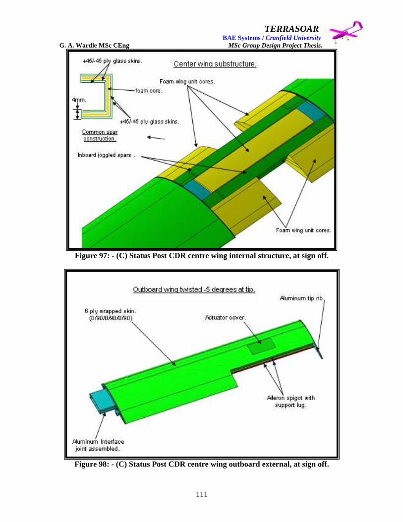
TERRASOAR BAE Systems / Cranfield University G. A. Wardle MSc CEng MSc Group Design Project Thesis.
111
Figure 97: - (C) Status Post CDR centre wing internal structure, at sign off.
Figure 98: - (C) Status Post CDR centre wing outboard external, at sign off.

TERRASOAR BAE Systems / Cranfield University G. A. Wardle MSc CEng MSc Group Design Project Thesis.
112
Figure 99: - (C) Status Post CDR centre wing outboard internal, at sign off.
Following the wing sign – off the wing skins and structural components were weighed
using the CATIA V4 model and the weights function the results of which are presented in
section 7. The Outer Mould Line surfaces were then released to Man Tech by the auth so
that they could commence tool design for the skin tools, and the pre - manufacturing (C)
Status model review was held on the 4th
October 2005.
4.7 Detailed design for BAE Systems manufacturing.
The major design decisions that resulted from the Man Tech (C) Status model review of
the 4th
October 2005 were as follows:-
Elimination of the ramps in the skin and spars of the centre section of the wing by
making the 9 ply zone continuous between the port and starboard wing joints:
Elimination of packers between the wing interface joints and the skin glue line
IML by locally growing out the interface joints:
Elimination of a separate foam packer to fill the gap under the actuator mounting
tray by use of an integral packer built into the outboard bottom wing skins:
Changing wing skin manufacture form the wrapped philosophy of the GDP wing
to two piece moulded skins to improve OML surface finish:
Wing / fuse attachment bolts to run normal to the attachment frames to ease
assembly:
Increase size of actuator cover plate to land on locally reinforced spars
eliminating the need for a separate landing frame:

TERRASOAR BAE Systems / Cranfield University G. A. Wardle MSc CEng MSc Group Design Project Thesis.
113
Figure 100: - Manufacturing maturation of Centre wing section structure.
Figure 101: - Manufacturing maturation of Centre wing top skin.
9 PLY CONTINUOUS ZONE TO SKIN LIMITS.
6 PLY AFT CONTINUOUS ZONES TO SKIN LIMITS.
6 PLY FWD CONTINUOUS ZONES TO SKIN LIMITS.
SKIN RAMPS

TERRASOAR BAE Systems / Cranfield University G. A. Wardle MSc CEng MSc Group Design Project Thesis.
114
Figure 102: - Manufacturing maturation of Centre wing bottom skin.
Figure 103: - Manufacturing maturation of Outboard wing bottom skin.
9 PLY CONTINUOUS ZONE TO SKIN LIMITS.
6 PLY FWD CONTINUOUS ZONES TO SKIN LIMITS.
6 PLY AFT CONTINUOUS ZONES TO SKIN LIMITS. SKIN RAMPS
SEALS
6 PLY OUTBOARD WING SKINS
INTEGRAL ACTUATOR PLATE PACKER
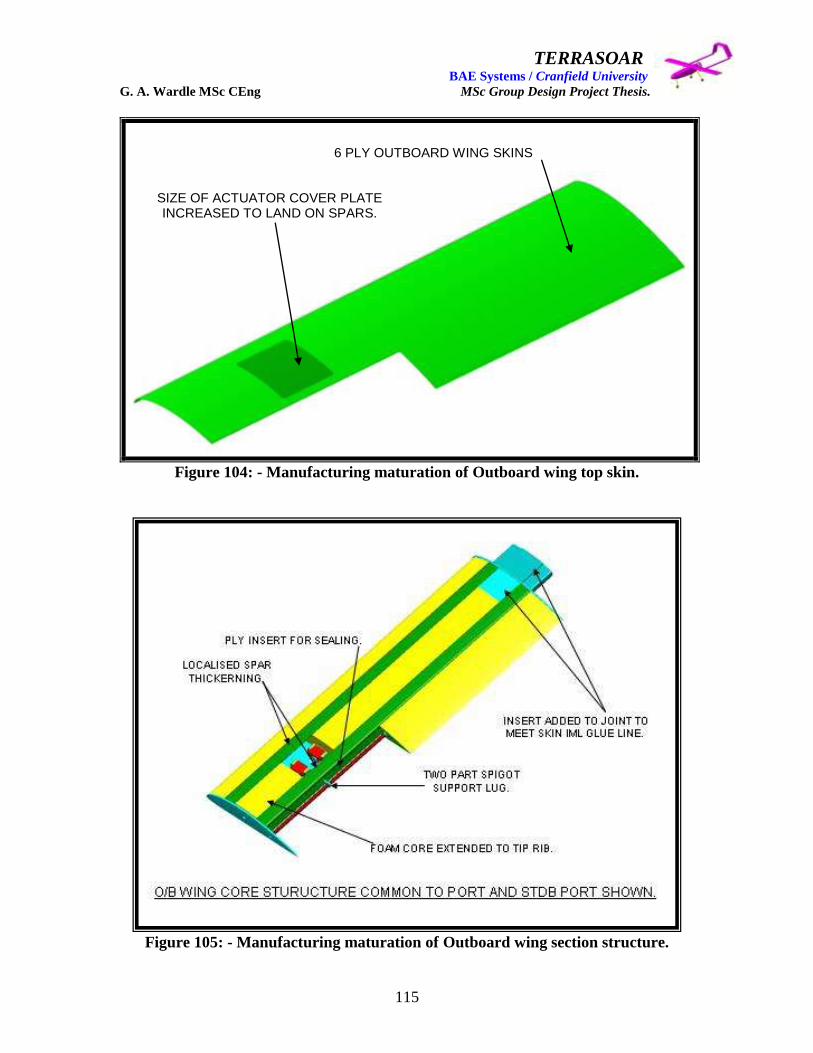
TERRASOAR BAE Systems / Cranfield University G. A. Wardle MSc CEng MSc Group Design Project Thesis.
115
Figure 104: - Manufacturing maturation of Outboard wing top skin.
Figure 105: - Manufacturing maturation of Outboard wing section structure.
6 PLY OUTBOARD WING SKINS
SIZE OF ACTUATOR COVER PLATE INCREASED TO LAND ON SPARS.

TERRASOAR BAE Systems / Cranfield University G. A. Wardle MSc CEng MSc Group Design Project Thesis.
116
Figure 106: - (C) Status development aileron structure.
Extension of the tip foam core to the tip rib:
Simplification of the tip rib navigation light integration:
And finally an initial definition of the aileron structure.
These modifications were duly incorporated by the author into the signed – off model and
are shown in figures 100 through 105 above, and the (C) Status structural configuration
for the ailerons is shown in figure 106 above, and the final manufacturable foam core
sandwich spar model was submitted to the Man Tech design review meeting on the 13th
October 2005. At this meeting the author was informed that the results draping tests on
the Alcan Airex R63.80 sandwich core foam had revealed problems in achieving the bend
radius required to manufacture the spars and a 4 - ply class only spar was proposed as a
solution to this problem. This resulted in a further IML modification of the spars for all
three sections of the wing and changes to the foam core OML‟s the resulting spar
thickness having decreased by 3mm, these modifications were conducted by the author,
and a final model was submitted to Man Tech on 12th
November 2005, for IML tool
design, which was the responsibility of Man Tech.
The responsibility for further design maturation of the aileron was formally passed to
BAE SYSTEMS New Business, Samlesbury Design Team, headed by Mr Peter
Hamilton, as was the responsibility for any minor wing modifications, on the 14th
November 2005.
4 PLY GLASS AILERON SKIN
4 PLY GLASS AILERON CLOSEURE SKIN IS NOT SHOWN FOR CLARITY
FOAM AILERON CORE
COMPOSITE AILERON DRIVE HORN
PLASTIC AILERON SPIGOT SHEATH

TERRASOAR BAE Systems / Cranfield University G. A. Wardle MSc CEng MSc Group Design Project Thesis.
117
5.0 Wing interface joint concept assessment and selection.
5.1: - PDR Trade Studies and (A) Status schemes.
As stated in section 4.3 above the major structural interface joints were a major
unresolved issue at PDR and the initial PDR and the author focused on the following
concepts for joint types: -
1. Wing to fuselage interface joint: - rib lugs with rose bearings attached by 5mm
diameter bolts through fuselage „U‟ section longerons which was the PDR
Submission Presentation, and is shown as figure 82 page 96, in this thesis.
2. Outboard wing sections to wing centre section interface joint: - aluminium tongue
extensions bonded and mechanically fastened into outboard wing spars and the
Rohacell foam core of the PDR wing these would then be slotted into cavities
between the centre wing spars and the foam core of the centre wing and would be
secured in place by counter sunk retaining bolts through the top and bottom wing
skins in to potted threaded inserts in the foam core.
3. The boom to wing interface joint: - initial consideration of this joint was to use
potted threaded inserts through the forward and aft spar flanges and into the
Rohacell foam core, to secure bolts which would attach through flanges in the
boom ends. A secondary concept was to use a common rib as both the outboard
wing section / wing centre section interface onto which the booms were pinned,
this concept was rejected out right because advisors felt skin stresses could not be
transferred across the joint however all of the stresses would have been carried by
the spars anyway.
5.1.1: - Post PDR (A) Status design study.
As stated in section four, after the visit to Slingsby Aviation the structural build
philosophy moved away from the heavy Rohacell core wing, and toward the much lighter
and more practical foam sandwich philosophy with interface ribs and sandwich skins.
This in turn impacted the interface joint philosophy and was also seen as an opportunity
to increase the fuel reserves to a more conservative level, than that which could be
accommodated in the PDR design.
The studies perused in the design week were as follows: -
1. Wing / Empennage Boom interface joint (author and James Pennington).
2. Wing / Fuselage interface joint (author and Paul Gilligan / James Pennington).
3. Centre wing / Outboard wing interface joint (author).
The results of these studies were carried over into the Post PDR (A) Status design study
detailed above in section four.

TERRASOAR BAE Systems / Cranfield University G. A. Wardle MSc CEng MSc Group Design Project Thesis.
118
5.1.2: - (A) Status Wing / Empennage Boom interface joints.
At this stage the Wing to Empennage / Boom interface was still a discrete joint inboard of
the wing interface and the Concept 1 pre – PDR study was a rib with lugs through the
forward and aft spar flanges and the bottom wing skins to which the Boom‟s were bolted
in a similar way to that originally proposed for the wing to fuselage interface joint at
PDR. This proposal in spite of being simple and practical was considered as too heavy for
this aircraft.
(a)
(b)
(c)
Figure 107: - Concept 2 / Wing to Empennage Boom interface joint, (a) lugs
attached to forward and aft spars: (b) channel section boom attached to lugs: (c)
boom skin covering joint.

TERRASOAR BAE Systems / Cranfield University G. A. Wardle MSc CEng MSc Group Design Project Thesis.
119
A lighter alternative to Concept 1 was proposed and is shown above in figure 107 this
was Concept 2 and utilised the same Boom arrangement as Concept 1 but the rib in the
wing was eliminated and instead the lugs were bolted directly through the spars which
would be locally reinforced. Plastic blocks filling the local spar „C‟ –section, would
house threaded inserts for the lug bolts to screw into, an alternative to this block
arrangement would have been anchor nuts adhesively bonded to the inside face of the
bottom flanges of each spar. This concept was carried through to Post PDR (A) Status
design study.
5.1.3: - (A) Status Wing / Fuselage interface joint.
Early in the design week Mr Peter Hamilton insisted that the longerons should be
eliminated from the fuselage design so the largest possible fuel tank could be housed
(whether required or not), and reliance should be placed in a stressed 2mm thick CFC
skin, although this skin had a large removable access panel, which did not bode well for
structural integrity.
After the visit to Slingsby Aviation and the identification of the new high rigidity
sandwich construction, elimination of the longerons which only spanned one bay
appeared to be a real possibility. The wing could then be raised above the fuselage so as
not to restrict the fuel tank growth (as stated in section three the fuel tank sizing was
based on an estimate because we still had no SFC data). James Pennington suggested a
hood attachment clipped to the fuselage sides with quick release latches which Paul
Gilligan agreed to source, I proposed that we would need a very good into wind lap joint
with blade or P - seals to cover the joint. The major problem would be drag and the
author and Mr James Pennington spent some considerable effort to create a blend, the
Globe Master 1 and the Shorts Sky Van had similar problems, but Terrasoar was
complicated by the need to blend over a short distance between the wing leading edge
and the forward fuel tank frame which was also the landing for the FCS removable access
panel. Neither the author nor Mr James Pennington were satisfied with the end result but
time was limited so this Concept 1 was presented at the GDP design review of the 17 / 11
/ 2004 as shown in figure 108 below.
Initially the Concept 1 hood was to be integral to the bottom wing skin but the complex
curvature and requirement for large bend radii rendered this solution impossible,
therefore the author proposed bonding the hood to the bottom wing skin and reinforcing
this joint with bolts through the forward and aft spars.
This concept was rejected by the Customer: - Cranfield University so no further work
was done on this concept study which was closed. This has lead to the greatly improved
and more efficient interface joint in the Interim Maturation design study described below.

TERRASOAR BAE Systems / Cranfield University G. A. Wardle MSc CEng MSc Group Design Project Thesis.
120
Wing / fuselage interface bonded to lower
skin and bolted to spars. Fitted with 4 quick
release clips to attach to the fuselage.Leading edge C section spar
broken at wing joints.
Trailing edge C section spar
broken at wing joints.
Torsion box closure ribs 2 places.
Wing section interface
joint (4 places).
Figure 108: - Post PDR (A) Status Wing / Fuselage attachment Concept 1.
5.1.4: - (A) Status Outboard wing / Centre wing interface joints.
After the Slingsby Aviation visit the author considered the PDR interface joint proposal
to be un - workable and started to study alternatives, at this time in the authors F-35 role
he was responsible for the wing fold joint, so an initial thought was to employ some of
the philosophies used in this key responsibility to create not a folding wing of course but
a multi lug pinned interface joint this is shown in figure 109. Ribs mounted in both the
outboard and centre wing sections have double staggered lugs for top and bottom pins
which are inserted through a cut out in the leading edge and screwed home into retained
nuts mounted in the trailing edge, and the skins extend over the interface with the
outboard skin slotting under the inboard skin to form a lap interface. A panel is then fitted
over the leading edge and secured with aero tape. This was Concept 1, however on the
scale at which we are working this solution although big and workable on the CATIA
screen becomes more like watch making in practice, and the integrity of the leading edge
cover panel would be in doubt, so this concept was shelved pre – Phase 1.

TERRASOAR BAE Systems / Cranfield University G. A. Wardle MSc CEng MSc Group Design Project Thesis.
121
Figure 109: - (A) Status Outboard Wing / Centre attachment Concept 1, in which
the outboard wing and centre wing lugged ribs are connected with two common
interface pins inserted through the leading edge (Starboard wing interface shown).
Concept 2 was to form a plug and slot interface between ribs mounted at the ends of the
torsion boxes of both outboard wing and the centre wing, this is shown in figure 110, a
quick release latch across the bottom tension skin of the interface would ensure there was
no risk of separation in flight. Because the top wing surface in flight is in compression
and the plug is nearly full chord a latch across to top skin would not be required.
Although this solution would have increased the wing weight by a small margin
minimum machining would have kept this low and it could have been traded off against
other areas of the structure. This concept was loosely based on some joints the author had
designed for the F-35 Horizontal Tail test box.
Centre wing section
rib with two lugs.
(Starboard)
Outboard wing sections rib
with three attachment lugs.
(Starboard)
Pin insertion from
wing leading edge.
Attachment pins.
Interface

TERRASOAR BAE Systems / Cranfield University G. A. Wardle MSc CEng MSc Group Design Project Thesis.
122
Figure 110: - (A) Status Outboard Wing / Centre attachment Concept 2, in which
the aluminium outboard wing rib has a tongue which slots into the aluminium
centre wing rib, and the joint is secured by a latch across the bottom skin.
(Starboard wing interface shown).
At the insistence of Peter Hamilton who believed there would be major corrosion
problems with the Concept 2 between the aluminium ribs and the “Carbon” skins, but the
author was not and never have proposing carbon fibre for the wing. He brought over one
of his „designers‟ from Nimrod and between them a wing joint I was unhappy with was
concocted and is shown here as Concept 3 in which bars pinned and wire locked through
„aluminium‟ inserts with class cloth backing (the wing spar skins are glass cloth but
neither of them took any notice) inserts carried the wing torsion loads, and wing bending
and were to be installed in both the leading forward and aft spar interfaces.
Concept 3 unfortunately was the only one to see visibility at the GDP meeting of the 17 /
11 / 2004 and was rejected by a much more experienced stress engineer who was present
to offer his assistance. This concept is shown below as figure 111.
Centre wing slotted rib
(Starboard).
Outboard wing tongued rib
(Starboard).
Latch across bottom tension
skin (omitted for clarity).
Hard mate joint at
rib interface.
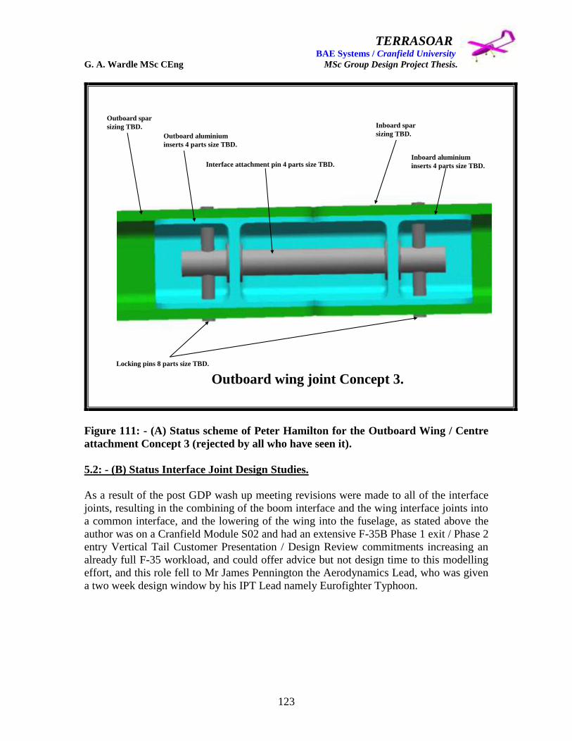
TERRASOAR BAE Systems / Cranfield University G. A. Wardle MSc CEng MSc Group Design Project Thesis.
123
Interface attachment pin 4 parts size TBD.
Locking pins 8 parts size TBD.
Outboard spar
sizing TBD.
Outboard aluminium
inserts 4 parts size TBD.
Inboard spar
sizing TBD.
Inboard aluminium
inserts 4 parts size TBD.
Outboard wing joint Concept 3.
Figure 111: - (A) Status scheme of Peter Hamilton for the Outboard Wing / Centre
attachment Concept 3 (rejected by all who have seen it).
5.2: - (B) Status Interface Joint Design Studies.
As a result of the post GDP wash up meeting revisions were made to all of the interface
joints, resulting in the combining of the boom interface and the wing interface joints into
a common interface, and the lowering of the wing into the fuselage, as stated above the
author was on a Cranfield Module S02 and had an extensive F-35B Phase 1 exit / Phase 2
entry Vertical Tail Customer Presentation / Design Review commitments increasing an
already full F-35 workload, and could offer advice but not design time to this modelling
effort, and this role fell to Mr James Pennington the Aerodynamics Lead, who was given
a two week design window by his IPT Lead namely Eurofighter Typhoon.

TERRASOAR BAE Systems / Cranfield University G. A. Wardle MSc CEng MSc Group Design Project Thesis.
124
5.2.1: - (B) Status Wing / Fuselage interface joint development for CDR.
The wing / fuselage interface joint has been considerably simplified and relies on two
sleeved bolts through the fuel tank frames as shown below in figure 112 and has been
approved by BAE Systems stress engineers and Terrasoar manufacturing, this joint still
requires assessment from the Fuel Lead to determine impact on fuel capacity.
Figure 112: - (B) Status Wing / Fuselage interface joint Concept 1, reviewed at the
Terrasoar „ALL HANDS‟ meeting of the 07 / 01 / 2005.
5.2.2: - (B) Status Wing / Empennage Boom and Outboard Wing interface joint for
CDR.
The current double duty inboard / outboard wing and wing / boom joint was devised by
James Pennington required some refinement however the general concept is sound and
was approved to go forward to be presented at CDR. This consists of the Outboard wing
and the Centre wing torsion box ribs forming a common interface, with lugs which are
force mated by a slotted Empennage boom attachment which is located by pinning
through both the attachment and the rib lugs, as shown in figure 113. The recommended
improvement was to add the tongue and slot interface from the (A) Status studies as
shown in figure 114.
Fwd /Aft sleeved bolts (2 off)
Fuel tank frames
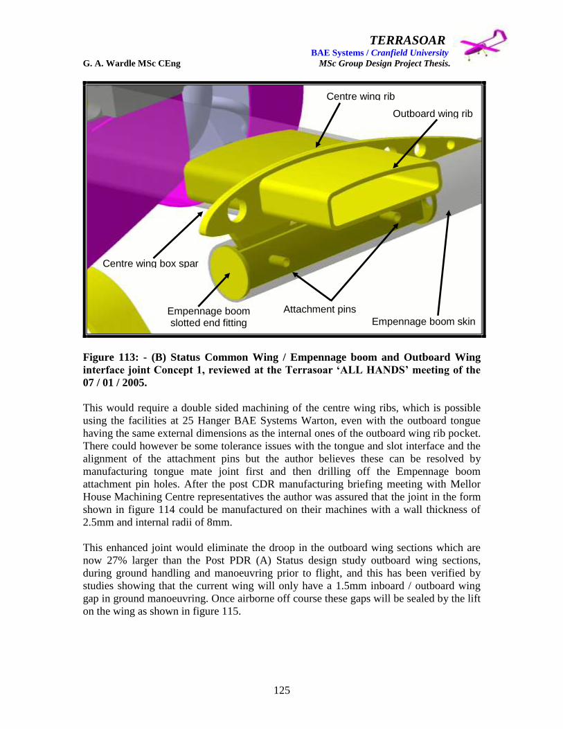
TERRASOAR BAE Systems / Cranfield University G. A. Wardle MSc CEng MSc Group Design Project Thesis.
125
Figure 113: - (B) Status Common Wing / Empennage boom and Outboard Wing
interface joint Concept 1, reviewed at the Terrasoar „ALL HANDS‟ meeting of the
07 / 01 / 2005.
This would require a double sided machining of the centre wing ribs, which is possible
using the facilities at 25 Hanger BAE Systems Warton, even with the outboard tongue
having the same external dimensions as the internal ones of the outboard wing rib pocket.
There could however be some tolerance issues with the tongue and slot interface and the
alignment of the attachment pins but the author believes these can be resolved by
manufacturing tongue mate joint first and then drilling off the Empennage boom
attachment pin holes. After the post CDR manufacturing briefing meeting with Mellor
House Machining Centre representatives the author was assured that the joint in the form
shown in figure 114 could be manufactured on their machines with a wall thickness of
2.5mm and internal radii of 8mm.
This enhanced joint would eliminate the droop in the outboard wing sections which are
now 27% larger than the Post PDR (A) Status design study outboard wing sections,
during ground handling and manoeuvring prior to flight, and this has been verified by
studies showing that the current wing will only have a 1.5mm inboard / outboard wing
gap in ground manoeuvring. Once airborne off course these gaps will be sealed by the lift
on the wing as shown in figure 115.
Empennage boom skin
Centre wing box spar
Centre wing rib
Outboard wing rib
Empennage boom slotted end fitting
Attachment pins
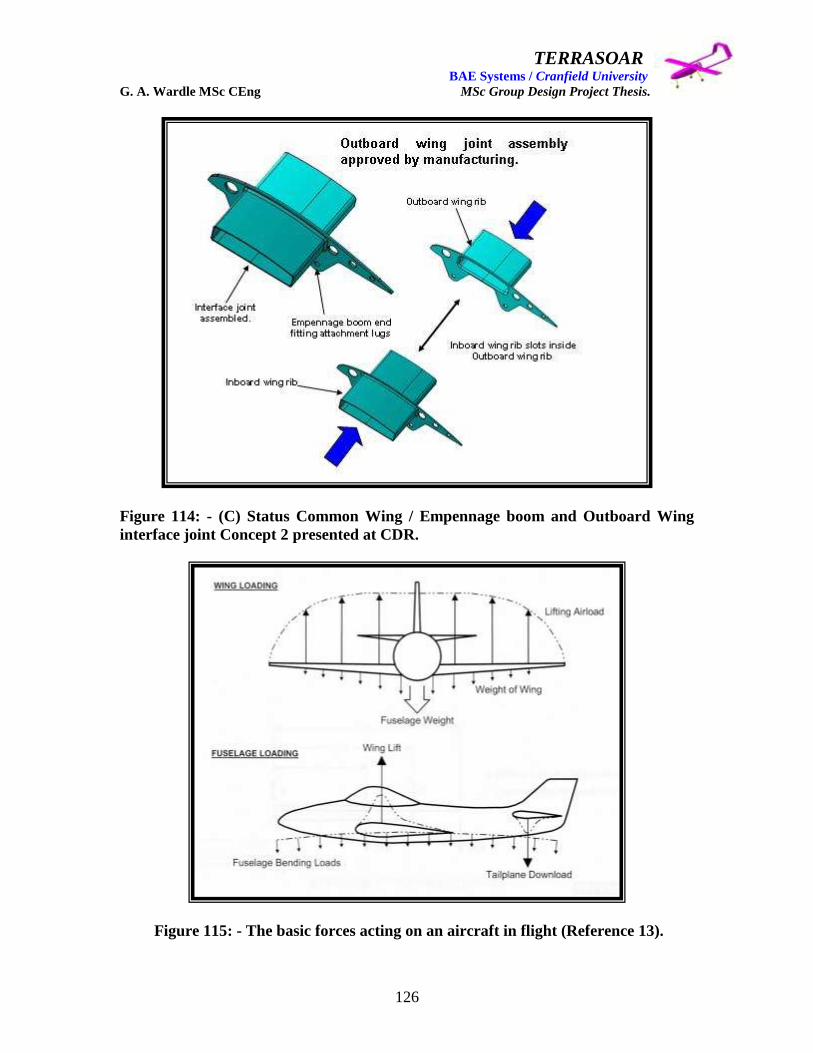
TERRASOAR BAE Systems / Cranfield University G. A. Wardle MSc CEng MSc Group Design Project Thesis.
126
Figure 114: - (C) Status Common Wing / Empennage boom and Outboard Wing
interface joint Concept 2 presented at CDR.
Figure 115: - The basic forces acting on an aircraft in flight (Reference 13).

TERRASOAR BAE Systems / Cranfield University G. A. Wardle MSc CEng MSc Group Design Project Thesis.
127
5.3: - (C) Status Interface Joint Design Maturation.
Immediately post CDR wing sign – off Mr Peter Hamilton insisted that a series of joint
weight reduction studies be conducted to lighten the ignoring the fact that most of the
wing weight was in the skins, and his calculations were based on the assumption that the
author had used 17 glass cloth plies in the design of the wing spars which was a totally
wrong assumption because at every meeting the wing spar structure had been explained
as being a foam cored sandwich. One of the weight reduction studies he was most
insistent was that shown in figure 116, which was actually heavier and more difficult to
machine than the CDR fixture, and was rejected by manufacturing, at Mellor House, and
by Man Tech.
Figure 116: - Post CDR weight reduction joint configuration proposed by Mr Peter
Hamilton and rejected by manufacturing.
The only real changes requested to aid assembly were those covered above in section 4.7,
namely the: -
1. Grow out of the top and bottom of the common wing / empennage interface joint
surfaces between the fwd and rear spars to meet the wing skin glue line IML and
modification to interface with the all glass 4 ply spars shown in figure 117:
2. The realignment of the wing / fuselage interface joint pins as shown in figure 118.

TERRASOAR BAE Systems / Cranfield University G. A. Wardle MSc CEng MSc Group Design Project Thesis.
128
Figure 117: - Post sign – off Common Wing / Empennage boom and Outboard Wing
interface joint manufacturing maturation.
Figure 118: - Post sign – off Wing / Fuselage attachment pin realignment
manufacturing maturation.
Top and bottom local surface grow out to meet skin IML.
Top and bottom local surface grow out to meet skin IML.

TERRASOAR BAE Systems / Cranfield University G. A. Wardle MSc CEng MSc Group Design Project Thesis.
129
Wing joint maturation in the form of detail OML change was handed over to BAE
SYSTEMS New Business, Samlesbury Design Team, headed by Mr Peter Hamilton, as
was the responsibility for any minor wing modifications, on the 14th
November 2005, and
this concluded joint maturation by the author.
6.0 Wing flight control surfaces and systems integration.
Aileron interface attachment, aileron design and integration of the aileron actuation
system and associated wiring will be covered in this section.
6.1: - (A) Status aileron attachment interface studies.
Initial studies by the author for PDR proposed that the wing fight control surfaces cold be
attached to the rear spar and supporting ribs by two hinges per aileron surface, and two
per flap. The main points to consider when mounting there surfaces are: -
1) The bending distortion of the control surface relative to the fixed surface of the wing
must be limited to prevent aileron reversal and the risk of the knuckle of the control
surface fouling the gap seals.
2) The control hinge loads and the resulting shear forces and bending moments should
be equalised as far as is possible.
3) Structural failure of a single hinge should be tolerated unless each hinge is of fail safe
design and can tolerate cracking in one load path.
Where only two hinge points are used as in the case of the Pre and Post PDR concepts
shown in section four and in figure 119, span -wise distortion or misalignment can be
overcome by designing one of the hinges so that it can rotate about a vertical axis as
shown in figure 120. This is called the floating hinge concept and is used to best effect on
two hinge systems. Considering the control surfaces to be uniform beams the
minimum deflection is experienced when the hinges support the beam at 55% of the
control surface span i.e. each hinge at 27.5% outboard of the control surface span-
wise centre as shown in figure 120.
The flight control surface attachment using the lug and clevis system which the author
devised in the Post PDR (A) Status design study in which equally spaced lugs on the
aileron were pinned into clevises mechanically fastened to the box spar using pinned
plate fitted from the inside of the box spar so that the pins pass through the box spar web,
was carried through to the Interim Maturation study prior to CDR.
The basic arrangement is shown in figure 119 had limitations and was complex to
assemble so a more workable solution was required for CDR. The intake 5 proposal of
installing piano hinge interface attachments would not work on the revised design due to
the wing twist of 20 additionally such hinges are prone to jamming under flight
conditions.

TERRASOAR BAE Systems / Cranfield University G. A. Wardle MSc CEng MSc Group Design Project Thesis.
130
Figure 119: - Post PDR (A) Status design study Wing / Aileron interface joint
(aileron design is covered in section 6.4 of this thesis).
Figure 120: - General arrangement of a two hinge plane flap illustrating the floating
hinge concept (Reference 17: - Howe. Denis, PhD: Aircraft Loading and Structural
Layout: Professional Engineering Publishing Ltd: 2004)
Knuckle
Flap CL

TERRASOAR BAE Systems / Cranfield University G. A. Wardle MSc CEng MSc Group Design Project Thesis.
131
6.2: - (B) Status aileron attachment interface studies for CDR.
As stated in the previous section the (A) Status wing / aileron interface attachment was
considered too complex for an aircraft of the Terrasoar size, but could be made to work
on a structural wing as conceived for the Post PDR (A) Status design study wing,
however this arrangement would have been difficult to implement on the Interim
Maturation design study wing with the integral box spar. However the Pre – CDR
revision outboard design wing offered new possibilities for a simpler wing / aileron
interface attachment therefore after consultation with Mr Robert Currie FCS lead and
keen large radio controlled aircraft model builder the philosophy of mounting the ailerons
on a single continuous spigot was proposed which considerably reduced complexity of
the interface and simplified the design of the aileron, as shown in figure 106 above and
described in section 6.4 below.
Figure 121: - (B) Status design study Wing / Aileron interface presented at CDR.
The authors resulting design is shown above as figure 121 and consisted of a threaded
insert adhesively bonded into a hole in the trailing edge foam, a 10mm diameter stainless
steel spigot threaded at one end, two plastic sleeves which one was to be bonded into
each aileron, and spigot receiving cup which was machined into the tip rib. The design as
shown in figure 121 was presented at CDR, were it was proposed by Mr Phil Stocking
that the spigot would require some additional support at mid – span to reduce the risk of
bending under flight control actuation loads.
Threaded insert potted into trailing edge foam.
Aileron spigot with plastic sleeve
Aileron mounted on spigot
Machined spigot cup in tip rib
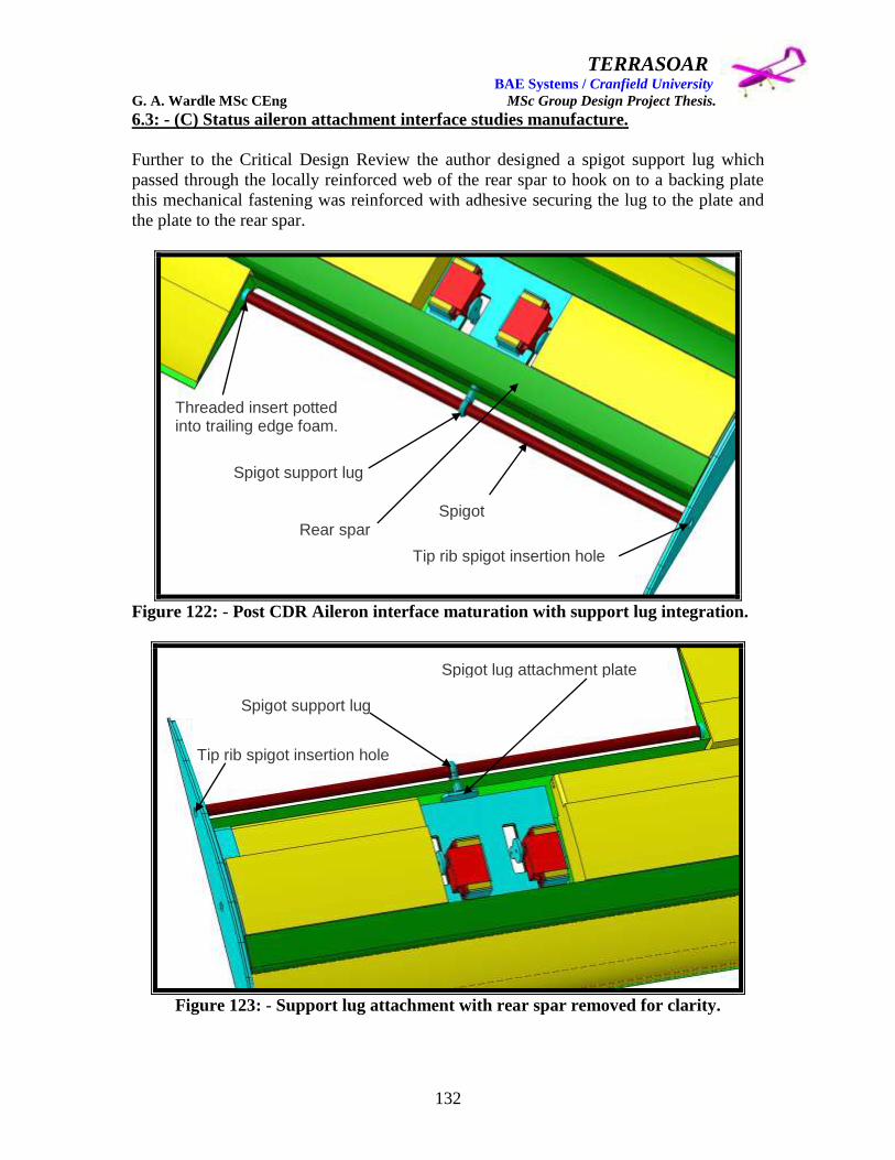
TERRASOAR BAE Systems / Cranfield University G. A. Wardle MSc CEng MSc Group Design Project Thesis.
132
6.3: - (C) Status aileron attachment interface studies manufacture.
Further to the Critical Design Review the author designed a spigot support lug which
passed through the locally reinforced web of the rear spar to hook on to a backing plate
this mechanical fastening was reinforced with adhesive securing the lug to the plate and
the plate to the rear spar.
Figure 122: - Post CDR Aileron interface maturation with support lug integration.
Figure 123: - Support lug attachment with rear spar removed for clarity.
Threaded insert potted into trailing edge foam.
Spigot support lug
Spigot support lug
Spigot lug attachment plate
Rear spar
Tip rib spigot insertion hole
Tip rib spigot insertion hole
Spigot

TERRASOAR BAE Systems / Cranfield University G. A. Wardle MSc CEng MSc Group Design Project Thesis.
133
The only other modification required post CDR was a request that the spigot be inserted
through the tip spar so that the tip spar could be used as the datum, and to that an
insertion hole was designed in through the bottom of the spigot tip rib location cup.
6.4: - (A) Status aileron design studies.
The initial pre –PDR control surface concept design studies were conducted by Mr David
Baird and Mr John Baggaley with Mr Baird being responsible for aileron design studies,
and these are included here for reference. After the departure of Mr Craig Carr from the
team Mr Baird took up his responsibilities and the design of the ailerons passed to the
author, and at the same time Mr Baggaley passed his elevator and rudder design
responsibilities to Mr James Pennington.
Figure 124: - David Baird‟s Pre – PDR (A) Status aileron design, shows a multi spar
design.
The first design concept from David Baird shown in figure 124 was a multi spar design
which although possibly possessing high rigidity would be complex to manufacture at the
Terrasoar scale. The second design concept from David Baird was both multi spar and
multi ribbed honey comb core aileron which appeared more complex than the first
concept.

TERRASOAR BAE Systems / Cranfield University G. A. Wardle MSc CEng MSc Group Design Project Thesis.
134
Figure 125: - David Baird‟s second Pre – PDR (A) Status aileron design, shows a
multi spar and multi rib design.
Figure 126: - David Baird‟s third PDR (A) Status aileron design, replaced the ribs
with foam.

TERRASOAR BAE Systems / Cranfield University G. A. Wardle MSc CEng MSc Group Design Project Thesis.
135
Mr David Baird‟s third and final concept removed the ribblets which were replaced with
higher density foam, but still had machined metallic closing ribs which appeared to the
author to be still too heavy and complex for the Terrasoar aircraft in view of its small
size, although this final design was considered suitable to be presented by Mr Baird at the
PDR review.
6.5: - (B) Status aileron design studies.
The Post PDR (A) Status wing design study gave an opportunity for the author to start
afresh with the aileron design as this responsibility had been passed over to him as stated
above. The first consideration was to maintain the aileron‟s stiffness whilst reducing its
weight and complexity. Form the first pre – PDR wing studies detailed in section four,
the intention was to mount two aileron pairs on each outboard wing section, therefore a
heavy complex solution would increase manufacturing time and could adversely impact
the aircrafts overall weight. The author therefore proposed the foam cored single spar
aileron, with no nose cell, wrapped in four ply fibreglass cloth at 00 / 90
0 / 0
0 / 90
0
orientations outward from the foam core which would act as the tool face. The spar
would be a „C‟ section of the same two ply fibreglass cloth / foam core / two ply
fibreglass cloth sandwich structure as the wing spars with the aluminium attachment lugs
and aileron drive horn recessed and adhesively bonded into the aileron core foam, and
this aileron is shown below in figure 127.
Figure 127: - The authors Post PDR (B) Status aileron design based on dimensions
supplied by Mr James Pennington and Miss Rachel Cunliffe (control sizing).
4 Ply glass cloth wrapped aileron skin
4 Ply glass cloth aileron closure skin is not shown for clarity
‘C’ Section spar imbedded in the foam core
Foam core
Recessed lugs
260.5mm
30.8mm
227.8mm

TERRASOAR BAE Systems / Cranfield University G. A. Wardle MSc CEng MSc Group Design Project Thesis.
136
6.6: - (C) Status aileron design study for CDR.
The changes to the outboard wing structural layout made to accommodate manufacturing
detailed above in section four lead to a reassessment of the aileron to wing attachment
philosophy as detailed in section five, and resulted in the single spigot method being
chosen by the author. In parallel this lead to a further aileron redesign which simplified
manufacture still further. This aileron consisted of a foam core airfoil shape with „D‟-
nose which was wrapped in four plies of fibreglass cloth, with a horizontal spigot hole
bored through housing a plastic sleeve to protect the core from abrasion from the spigot.
Initially the aileron drive horn was aluminium and recessed and bonded in place as was
the case with the previous (B) status aileron detailed in the above section, and this
configuration was presented at the CDR review. Post CDR studies demonstrated the
availability of composite actuation horns as COTS items shown in section 6.7 and these
could be more easily integrated into the foam core and cover skin. This matured (C)
status design is shown below as figure 128.
Figure 128: - The authors Post CDR (C) Status aileron design based on dimensions
supplied by Mr James Pennington and Miss Rachel Cunliffe (control sizing).
This final design has been submitted to Man Tech for OML foam machining and
manufacturing maturation. All further aileron development is the responsibility of BAE
SYSTEMS New Business at Samlesbury.
4 Ply glass cloth wrapped skin
Foam core
4 Ply glass cloth aileron closure skin is not shown for clarity
Composite horn
Plastic sheath liner
Spigot hole
129.6mm
253.7mm
33.9mm
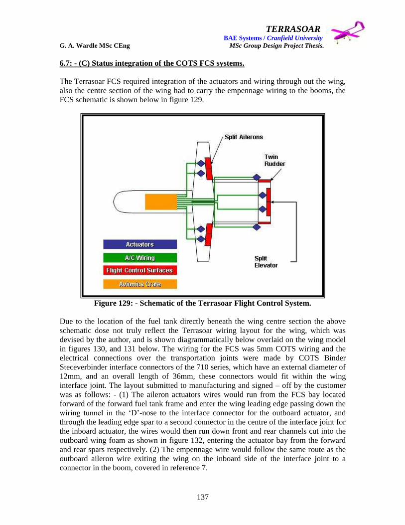
TERRASOAR BAE Systems / Cranfield University G. A. Wardle MSc CEng MSc Group Design Project Thesis.
137
6.7: - (C) Status integration of the COTS FCS systems.
The Terrasoar FCS required integration of the actuators and wiring through out the wing,
also the centre section of the wing had to carry the empennage wiring to the booms, the
FCS schematic is shown below in figure 129.
Figure 129: - Schematic of the Terrasoar Flight Control System.
Due to the location of the fuel tank directly beneath the wing centre section the above
schematic dose not truly reflect the Terrasoar wiring layout for the wing, which was
devised by the author, and is shown diagrammatically below overlaid on the wing model
in figures 130, and 131 below. The wiring for the FCS was 5mm COTS wiring and the
electrical connections over the transportation joints were made by COTS Binder
Steceverbinder interface connectors of the 710 series, which have an external diameter of
12mm, and an overall length of 36mm, these connectors would fit within the wing
interface joint. The layout submitted to manufacturing and signed – off by the customer
was as follows: - (1) The aileron actuators wires would run from the FCS bay located
forward of the forward fuel tank frame and enter the wing leading edge passing down the
wiring tunnel in the „D‟-nose to the interface connector for the outboard actuator, and
through the leading edge spar to a second connector in the centre of the interface joint for
the inboard actuator, the wires would then run down front and rear channels cut into the
outboard wing foam as shown in figure 132, entering the actuator bay from the forward
and rear spars respectively. (2) The empennage wire would follow the same route as the
outboard aileron wire exiting the wing on the inboard side of the interface joint to a
connector in the boom, covered in reference 7.

TERRASOAR BAE Systems / Cranfield University G. A. Wardle MSc CEng MSc Group Design Project Thesis.
138
Figure 130: - FCS Actuator wiring and connections at the Terrasoar wing interface.
Figure 131: - FCS actuator wires in the Terrasoar outboard wing.
Inboard Actuator wiring route
Outboard Actuator
wiring route Empennage Actuator
wiring route
Inboard Actuator wiring route
Outboard Actuator wiring route Foam core
Forward spar
Rear spar

TERRASOAR BAE Systems / Cranfield University G. A. Wardle MSc CEng MSc Group Design Project Thesis.
139
Figure 132: - Actuator wiring channels in the Terrasoar outboard wing.
The wiring route for the navigation lights has still to be defined at the time of writing but
the author‟s current proposal is to run the wing tip lights down the same route as the
inboard actuator exiting at the wing tip rib.
Figure 133: - Aileron actuator installation.
Inboard Actuator wiring channel
Outboard Actuator wiring channel
Forward spar
landing
Rear spar landing

TERRASOAR BAE Systems / Cranfield University G. A. Wardle MSc CEng MSc Group Design Project Thesis.
140
The aileron actuators are mounted on a single aluminium tray which is machined to
minimum thickness as shown in figure 133 the actuators themselves are screwed into
spacer blocks which are then push filled into securing grow outs from the mounting plate
this gives the actuators an interference fit and secures them in place though out the flight
envelope. These actuators drive the ailerons through adjustable push pull rods as shown
in figure 134 below these are COTS items and are shown with aileron drive attachment
horns in figure 135 below.
Figure 134: - Aileron actuator drive mechanism
.
Figure 135: - Aileron horns and actuator drive rods
Adjustable push – pull rod
Aileron horn
Actuator horn
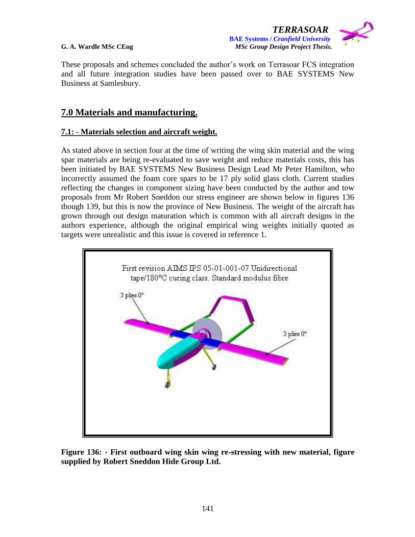
TERRASOAR BAE Systems / Cranfield University G. A. Wardle MSc CEng MSc Group Design Project Thesis.
141
These proposals and schemes concluded the author‟s work on Terrasoar FCS integration
and all future integration studies have been passed over to BAE SYSTEMS New
Business at Samlesbury.
7.0 Materials and manufacturing.
7.1: - Materials selection and aircraft weight.
As stated above in section four at the time of writing the wing skin material and the wing
spar materials are being re-evaluated to save weight and reduce materials costs, this has
been initiated by BAE SYSTEMS New Business Design Lead Mr Peter Hamilton, who
incorrectly assumed the foam core spars to be 17 ply solid glass cloth. Current studies
reflecting the changes in component sizing have been conducted by the author and tow
proposals from Mr Robert Sneddon our stress engineer are shown below in figures 136
though 139, but this is now the province of New Business. The weight of the aircraft has
grown through out design maturation which is common with all aircraft designs in the
authors experience, although the original empirical wing weights initially quoted as
targets were unrealistic and this issue is covered in reference 1.
Figure 136: - First outboard wing skin wing re-stressing with new material, figure
supplied by Robert Sneddon Hide Group Ltd.

TERRASOAR BAE Systems / Cranfield University G. A. Wardle MSc CEng MSc Group Design Project Thesis.
142
Figure 137: - First inboard wing skin wing re-stressing with new material figure
supplied by Robert Sneddon Hide Group Ltd.
Figure 138: - Second outboard wing skin wing re-stressing with new material figure
supplied by Robert Sneddon Hide Group Ltd.
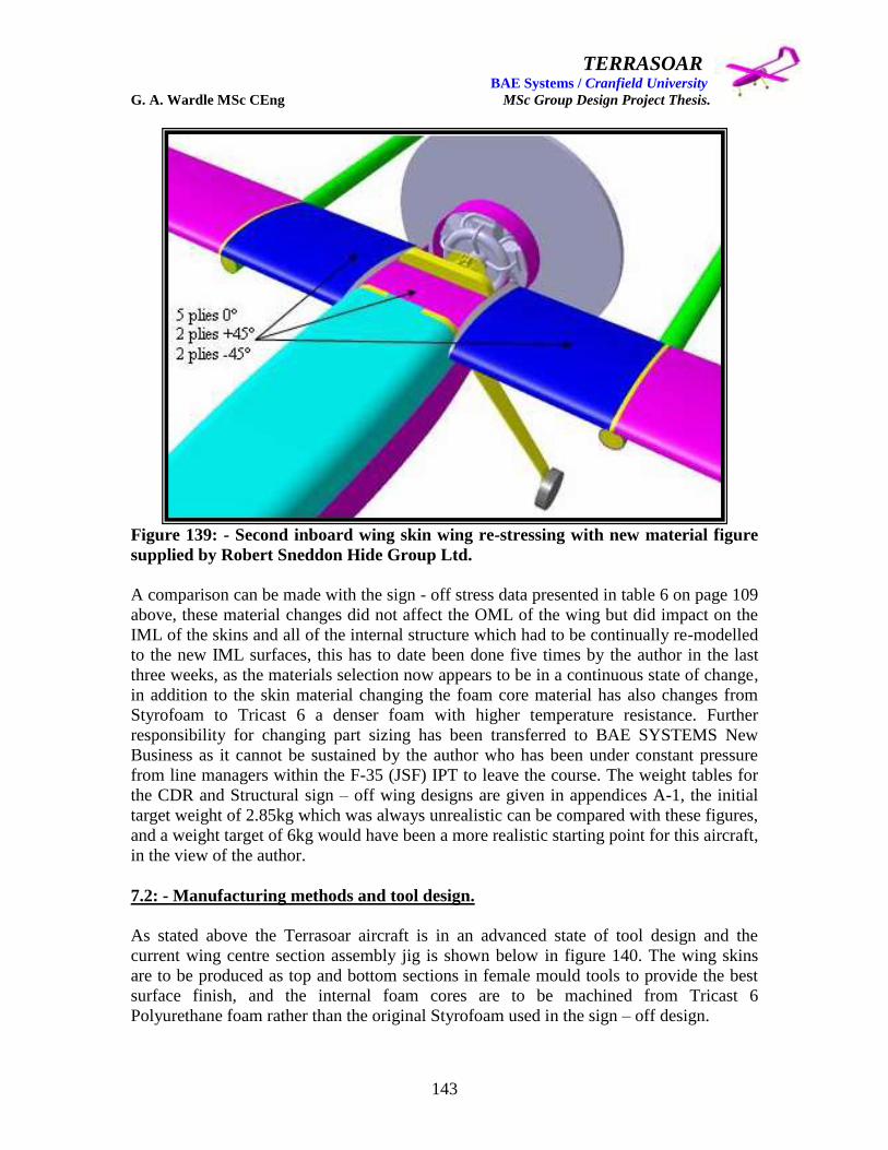
TERRASOAR BAE Systems / Cranfield University G. A. Wardle MSc CEng MSc Group Design Project Thesis.
143
Figure 139: - Second inboard wing skin wing re-stressing with new material figure
supplied by Robert Sneddon Hide Group Ltd.
A comparison can be made with the sign - off stress data presented in table 6 on page 109
above, these material changes did not affect the OML of the wing but did impact on the
IML of the skins and all of the internal structure which had to be continually re-modelled
to the new IML surfaces, this has to date been done five times by the author in the last
three weeks, as the materials selection now appears to be in a continuous state of change,
in addition to the skin material changing the foam core material has also changes from
Styrofoam to Tricast 6 a denser foam with higher temperature resistance. Further
responsibility for changing part sizing has been transferred to BAE SYSTEMS New
Business as it cannot be sustained by the author who has been under constant pressure
from line managers within the F-35 (JSF) IPT to leave the course. The weight tables for
the CDR and Structural sign – off wing designs are given in appendices A-1, the initial
target weight of 2.85kg which was always unrealistic can be compared with these figures,
and a weight target of 6kg would have been a more realistic starting point for this aircraft,
in the view of the author.
7.2: - Manufacturing methods and tool design.
As stated above the Terrasoar aircraft is in an advanced state of tool design and the
current wing centre section assembly jig is shown below in figure 140. The wing skins
are to be produced as top and bottom sections in female mould tools to provide the best
surface finish, and the internal foam cores are to be machined from Tricast 6
Polyurethane foam rather than the original Styrofoam used in the sign – off design.
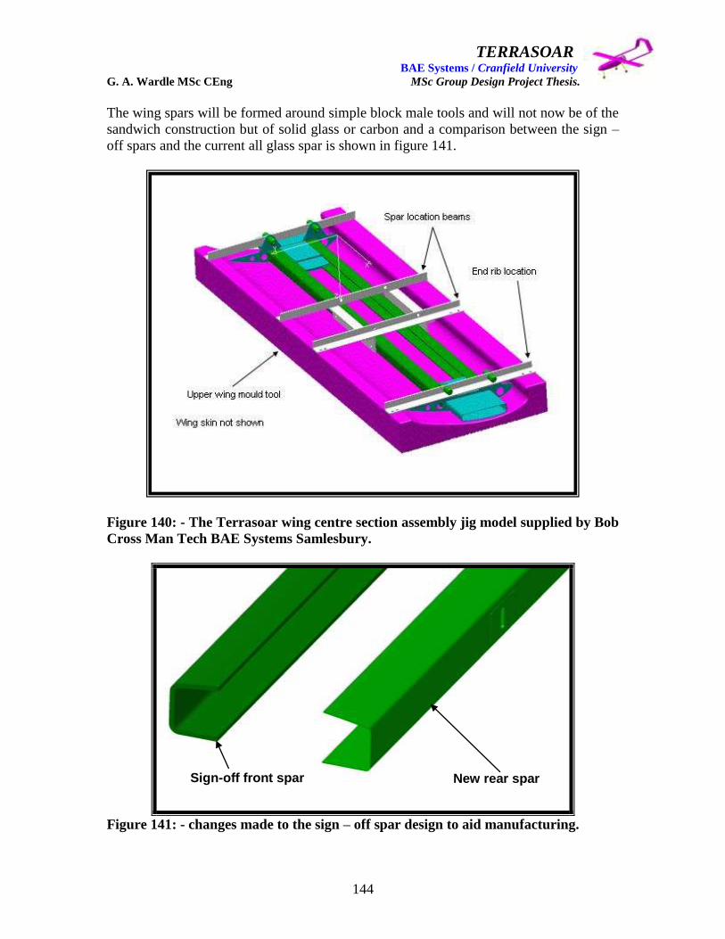
TERRASOAR BAE Systems / Cranfield University G. A. Wardle MSc CEng MSc Group Design Project Thesis.
144
The wing spars will be formed around simple block male tools and will not now be of the
sandwich construction but of solid glass or carbon and a comparison between the sign –
off spars and the current all glass spar is shown in figure 141.
Figure 140: - The Terrasoar wing centre section assembly jig model supplied by Bob
Cross Man Tech BAE Systems Samlesbury.
Figure 141: - changes made to the sign – off spar design to aid manufacturing.
Sign-off front spar New rear spar
TERRASOAR BAE Systems / Cranfield University G. A. Wardle MSc CEng MSc Group Design Project Thesis.
145
All further changes are now the responsibility of BAE SYSTEMS New Business Design
Lead Mr Peter Hamilton.
7.3: - Structural test and qualification proposal.
Airframe structural design requires a continuing assessment of structural function to
determine whether or not the requirements have been satisfied.
The expected service performance must be satisfied before the structure enters the service
environment. This assessment is the structural testing which will ensure and substantiate
structural integrity per certification for either civil or military requirements. The basic
“building block” approach, shown in figure 142, for testing of anisotropic laminate
structures should be established at the early stages of development because the validation
process for composite structures is very dependant on testing of all levels of the
fabrication process.
Composite structural testing is similar to most metallic structural testing (the majority of
metallic testing procedures are applicable to composite structures) in that it requires
knowledge of design and analysis. The difference is that composites behave
anisotropically and need thorough experimental testing, not only of the structure as a
whole, but also of test specimens at the coupon, element, and component levels.
Design with composite materials requires knowledge of lamination theory and
appropriate failure criteria as well as related analysis. These analyses must deal with the
new set of material properties that result from the making of the laminate. Laminate
properties test results are not useful to the engineer until the data is reduced, and
translated into design allowables, and then reported in a standard format that can be
clearly understood with no ambiguity.
Due to the constraints of this thesis it is only practical to present an overview of the
structural testing and inspection required to meet the airworthiness type certification
requirements for a composite wing box structure, there is neither space nor time to detail
each and every test required or inspection procedure, but this can be found in the
reference material used to compile text.
At the outset this is a proposal and not a definitive statement of work, and is also
dependent on the type of material ultimately selected for the Terrasoar wing manufacture,
which may ultimately be a better known CFC composite with which BAE Systems has
enough experience to make coupon testing unnecessary.
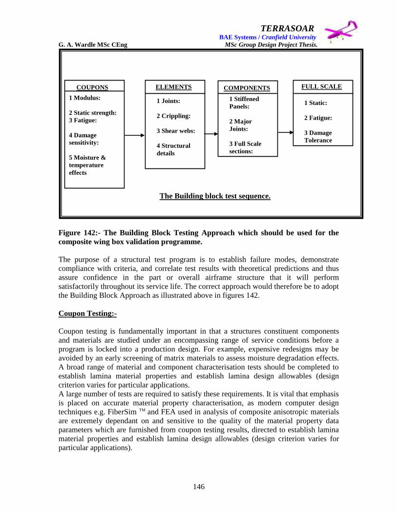
TERRASOAR BAE Systems / Cranfield University G. A. Wardle MSc CEng MSc Group Design Project Thesis.
146
Figure 142:- The Building Block Testing Approach which should be used for the
composite wing box validation programme.
The purpose of a structural test program is to establish failure modes, demonstrate
compliance with criteria, and correlate test results with theoretical predictions and thus
assure confidence in the part or overall airframe structure that it will perform
satisfactorily throughout its service life. The correct approach would therefore be to adopt
the Building Block Approach as illustrated above in figures 142.
Coupon Testing:-
Coupon testing is fundamentally important in that a structures constituent components
and materials are studied under an encompassing range of service conditions before a
program is locked into a production design. For example, expensive redesigns may be
avoided by an early screening of matrix materials to assess moisture degradation effects.
A broad range of material and component characterisation tests should be completed to
establish lamina material properties and establish lamina design allowables (design
criterion varies for particular applications.
A large number of tests are required to satisfy these requirements. It is vital that emphasis
is placed on accurate material property characterisation, as modern computer design
techniques e.g. FiberSim TM and FEA used in analysis of composite anisotropic materials
are extremely dependant on and sensitive to the quality of the material property data
parameters which are furnished from coupon testing results, directed to establish lamina
material properties and establish lamina design allowables (design criterion varies for
particular applications).
COUPONS
1 Modulus:
2 Static strength:
3 Fatigue:
4 Damage
sensitivity:
5 Moisture &
temperature
effects
ELEMENTS
1 Joints:
2 Crippling:
3 Shear webs:
4 Structural
details
COMPONENTS FULL SCALE
1 Stiffened
Panels:
2 Major
Joints:
3 Full Scale
sections:
4 Structural
details
1 Static:
2 Fatigue:
3 Damage
Tolerance
The Building block test sequence.

TERRASOAR BAE Systems / Cranfield University G. A. Wardle MSc CEng MSc Group Design Project Thesis.
147
Single ply (lamina: tape or fabric) properties are obtained experimentally from multi-ply
unidirectional laminate specimens where all plies have the same orientation. For tape
laminates with all fibres aligned in the same direction (also tests on cross – plied
laminates can be considered to determine unidirectional properties), the ply properties
needed for design are: -
Ultimate strength values:
Elastic constraints
Poisson‟s ratio values.
Test coupons that are designed to be weighed during the conditioning process should be
weighed immediately after fabrication. All of the coupons are then stored in a dry
desiccated chamber prior to conditioning. It is vitally important that the fibre volume and
void content of each coupon is known. Moisture is absorbed by the matrix, so the
percentage of matrix in a given coupon will affect the amount of moisture absorbed. The
size and concentration of voids present in the coupon must also be known. The relative
humidity in the conditioning environmental chamber will determine the maximum
moisture content of the conditioned test coupons in this conditioning. Table 7 illustrates
the effect of Fibre Volume Percentage (FVP) on the mechanical properties of laminate
test coupons.
There are several basic coupon tests which would form the basis of a building block test
program aimed at validating a composite wing box structure, and these would deliver an
adequate design database, for establishing the design properties of the material system
and identify the most critical environmental exposures including humidity and
temperature. These tests are outlined below: -
1. Tensile tests: - The strain measurements of composite coupons can be sensitive to
the coupon configurations (configuration dose not effect such testing in metals).
Therefore unidirectional test coupons for modulus tests only, require special load
introduction tabs, but multidirectional test coupons do not. (Test coupon
configurations are detailed in reference 18 Composite Materials for Aircraft
Structures 2nd
Edition: Baker. A: AIAA Education Series: 2004).
2. Compression tests: - The measured strain for compression coupons is sensitive to
coupon configuration, and the fixture used for loading. The coupon must be
constrained from buckling, and the recommended test fixtures detailed in
reference 1 are based on those developed for unidirectional coupon testing.

TERRASOAR BAE Systems / Cranfield University G. A. Wardle MSc CEng MSc Group Design Project Thesis.
148
Table 7: - Effect of FVP on mechanical properties of test laminates.
Properties Effect of FVP on laminate mechanical properties*.
[0]nt [90]nt [+/-45]ns [(+/-45)5/016/904]c
Ultimate
Strength.
Varies directly
with FVP
Not sensitive
to FVP
Varies directly
with FVP
Varies directly with
FVP
Ultimate
strain
Not sensitive
to FVP
Not sensitive
to FVP
Not sensitive
to FVP
Not sensitive to
FVP
Prop. Limit
Stress
Varies directly
with FVP
Not sensitive
to FVP
Varies directly
with FVP
Varies directly with
FVP
Prop. Limit
Strain
Varies directly
with FVP
Not sensitive
to FVP
Varies directly
with FVP
Varies directly with
FVP
Poisson‟s ratio Not sensitive
to FVP
Not sensitive
to FVP
Varies directly
with FVP
Not sensitive to
FVP
Modulus of
elasticity
Varies directly
with FVP
Varies directly
with FVP
Varies directly
with FVP
Varies directly with
FVP
*The above deductions are valid for both tensile and compressive properties.
3. Shear tests: - There are numerous shear test methods which are covered in detail
in reference 16, some of the most important ASTM (American Society for Testing
and Materials) methods are listed below in table 8
Table 8: - ASTM Shear coupon composite shear tests.
ASTM Type Description
D2344 Interlaminar Short beam shear (3-point)
D3846 Interlaminar Short beam shear (4-point)
D3518 Inplane +/- 45o tensile test
D4255 Inplane Rail shear
4. Flexural tests: - These are not considered an intrinsic property, but the test is
inexpensive to run and is considered a good quality control test Reference 16: -
Anon ,”Standard Test Methods for Flexural Properties of Unreinforced and
Reinforced Plastics and Electrical Insulating Materials”, D790, Annual Book of
ASTM Standards, ASTM, is the most quoted source for test methods.

TERRASOAR BAE Systems / Cranfield University G. A. Wardle MSc CEng MSc Group Design Project Thesis.
149
5. Short Beam tests: - This test is useful for evaluating the interlaminar shear
behaviour of the laminate matrix. This test is generally accepted as a method for
obtaining a qualitative measure of the laminate matrix condition rather than a
procedure for generating valid design data. Processing variables which affect the
test results are: -
Elevated temperature
Matrix moisture content
General matrix condition
6. Moisture and temperature tests: - At ply – level or coupon level there is a need to
test due to the physical compliance of the laminate which is usually accounted for
by ply – level properties. These moisture and temperature effects are accounted
for in stress analysis of the structure by using a reduced allowable.
7. Notch testing: - The notch tension and compression tests are conducted to
determine the most damaging combinations of stress raiser, temperature, and
moisture. The effect of the hole diameter size (fasteners) on residual tensile and
compression strength are evaluated based on given test requirements. Tests are
conducted for several for several hole sizes larger than baseline hole e.g. 0.25inch
(6.35mm) is the most common baseline with a w/d ratio of 6. The tests are
conducted for the most critical environmental condition determined from the
tension and compression tests. The ratio of hole diameter to coupon width will be
the same for all coupons. A reduction factor as a function of increasing hole
diameter is determined from these tests.
8. Impact testing: - Impact testing of coupons in which the coupon is subjected to a
single impact and then compression tested does not give an accurate indication of
suitable design properties and is merely used to compare material characteristics.
The impact testing to determine design values should be done on components and
/ or full scale test structures.
9. Fastener bearing and pull – trough tests: - (A) Fastener bearing strength for tape
composites is a function of the lay - up
The 100% 0o ply laminate would fail by shear tear out, and strength would be
essentially a function of shear strength of the matrix and the cross – sectional area
to the edge of the coupon:
The 100% 90o ply laminate would fail by net section tension and strength would
be a function of the matrix tensile strength and the net cross – sectional area:
Both of these are comparatively weak failure modes, multi – directional
reinforcement is required if appreciable bearing strength is to be obtained.
The bearing strength allowable can be determined from the following equation: -

TERRASOAR BAE Systems / Cranfield University G. A. Wardle MSc CEng MSc Group Design Project Thesis.
150
Fbru = Fbr x Ke x Kcsk (equation 1.1)
Where: - Fbr = “B” allowable for room temperature dry (RTD) bearing strength of
non – countersunk holes:
Ke = Environmental correction factor:
Kcsk = Countersunk correction factor.
The “B” bearing allowable for a non – countersunk hole RTD condition is
modified by Ke and Kcsk to account for environment, t/d, w/d, single lap shear
etc. and countersunk thickness for flush fasteners. To determine the Fbr allowable,
tests would be conducted on double lap shear coupons, made from several
different laminate thicknesses. These test results would then be pooled to establish
a “B” bearing allowable. The test for extreme environmental conditions, are used
to provide the Ke environmental correction factors. Each coupon used to test
environmental conditions would be cut from the same location in the laminates.
Then the ratio of the environmental bearing strength to the RTD bearing strength
can be used for statistical analysis. The bearing tests for fabric laminates would be
similar to the tests for tape laminates.
(B) Pull – through tests: - The pull – through test, is conducted to determine the
load required to pull fasteners through composite laminates. This property is
important for structures subjected to internal pressure loads such as integral wing
fuel tanks, or to permit buckling of skins (or webs) without failure at fastener
attachments. The majority of failures of secondary supports, (e.g. secondary tension
due to diagonal tension shear buckling effect) are in the form of fasteners pulling
through laminates, particularly countersunk fastener heads. Composites are
generally weak in pull – through strength. Pull – through strength is a function of: -
Laminate thickness:
Fastener diameter:
Configuration of fastener head type:
Laminate deflection.
Therefore, tests need to be conducted for several thicknesses, fastener diameters,
and fasteners head types. Laminate support should supply rigidity of the same order
as that expected for the structure.
10. Process Control Testing: - The above testing is primarily qualification and
acceptance testing, were as process control testing is the next step in the test
program, (see figure 143 and is derived to ensure that the fabrication process is
working as it is supposed to work. The concept is derived from the early days of
metal bonded structures when adhesive qualification coupons were run along with
bonded assemblies. As they were processed together, if the coupon tests were
successful this was taken as evidence that the process was being adequately
performed. This concept was extended to composites and travellers (tag end
coupons) are manufactured with composite components with the following
considerations: -

TERRASOAR BAE Systems / Cranfield University G. A. Wardle MSc CEng MSc Group Design Project Thesis.
151
a. The test specimen must reflect the process (cure cycle) that is occurring at critical
locations (often more than one on large complex parts). This means the significant
factors in the process must be reflected in the fabrication of the test coupon.
b. The coupon should be made along with the part (same material, same exposure to
contamination in addition to the cure cycle).
c. The coupon should be a standardised type so that acceptance criteria can be
established with statistical relevance.
d. The method should be simple enough to be systemised to the point that only
manufacturing quality control interface is involved. Airframe engineering should
only become involved during set – up and when deviations to the requirements
occur.
Tests must satisfy items (a) and (b) above and should be conducted on pieces trimmed
from production parts. However, this approach is contrary to items (c) and (d)
requirements and therefore requires a trade – off study for cost effectively.
Figure 143: - Materials Qualification Tests V‟s, Batch Acceptance Tag – End Tests,
for the coupon test program.
Candidate material
Submitted.
Materials lab.
Qualification test
performed.
Airframe Engineering.
Test results reviewed.
(a) Material qualification tests.
(b) Batch acceptance and tag end test.
Material lot
received.
Materials lab.
Batch acceptance
tests performed.
Production.
Parts and tag ends
layed up.
Materials lab.
Tag end tests
performed.
Production.
Clearance to continue
fabrication.

TERRASOAR BAE Systems / Cranfield University G. A. Wardle MSc CEng MSc Group Design Project Thesis.
152
Some elevated temperature moisture coupon testing data would be used in support of
element testing to meet certification requirements.
Element and component tests: -
Element and component testing represents the second and third blocks in the building
block composite certification test program shown in figure 142, although there is a
growing opinion that these tests can be reduced and substituted by computer analysis
tools based on FEA and structural optimisation software. However currently and for the
foreseeable future representative structural element testing will play a key role in
composite airframe certification programs. Figure 144 shows typical structural elements
and components used for allowables verification, and fulfilment of both static and fatigue
/ damage tolerance structural integrity requirements. Such elements contain detail
features such as holes, notches, stringer run – outs, joggles, etc, and the objective of
element and component testing is to determine what effect these features have on the total
structure, for example:-
An access hole through a skin structure may drastically alter the stress
concentration and redistribution in the surrounding area:
A fastened bonded and / or fastened joint may also produce significant stress
perturbations in the joints immediate vicinity:
These sections of components may induce large stress perturbations in the
constitutive material and induce failure modes very different from those predicted
by laminate theory:
In addition to inplane axial and shear loads, concentrated normal tension load on a
composite integrally stiffened panel, can be used to determine the flatwise tension
and peel strength between the skin and stiffener which are much lower than
inplane laminate strengths, hence stiffener pull – off strength tests would be
conducted as part of the wing structure qualification program.
Element and component testing will require much more instrumentation and have more
complicated load introduction and test fixtures than coupon testing therefore this form of
testing is more expensive, but yields a much more accurate picture of structural
behaviour.
This element and component testing would be used to cover the element and component
level testing for both the Proof of Structure: - Static and Fatigue / Damage Tolerance
requirements.

TERRASOAR BAE Systems / Cranfield University G. A. Wardle MSc CEng MSc Group Design Project Thesis.
153
Figure 144:- Component Tests (DC-10 Vertical Composite Fin Box) (reference 16).
Joint Design evaluation: - One of the most difficult aspects of joint testing is inducing
the loads into the joint in a fashion which is representative of the boundary conditions of
a test article. For example, it may be difficult or virtually impossible to determine, much
less duplicate in a test, the stiffness boundary conditions which are present at the joint in
actual service. The choice of boundary conditions which are readily reproducible in most
tests consist of either free or fixed supports, which usually have a very high reserve factor
on them for BAE Systems STF in the order of 4. Based on previous testing on legacy
aircraft information may be available as to the procedure and gripping hardware which
would be most appropriate for approximating in situ conditions, such as historical tests on
Airbus A320‟s empennage which could be applied to the A400M wing testing. The
service stress distribution in the components which border the joint would then have to be
predicted by analytical methods probably FEA modelling. Then it is possible to
approximate the same stress proportions by using boundary control techniques which are
related to an active feedback signal from the component under test. Such a test would be
expensive, but the application may be critical enough to warrant resorting to such a
technique, for example: - the adhesively bonded spar to bottom wing skin joints. These
tests would be conducted in the hot / wet condition as described for coupon testing in
section above.
TERRASOAR BAE Systems / Cranfield University G. A. Wardle MSc CEng MSc Group Design Project Thesis.
154
Cut – outs: - Obviously, small coupon test specimens are inappropriate for evaluating the
effects of cut – outs, or large flaws unless the imperfection being assessed is small
compared to the coupon width; coupons can also be adversely affected by free edge stress
effects. Therefore panel tests with major and minor dimensions close to that of the actual
structure would be used for notch, cut – out or imperfection tests.
In composite structures, a large cut – outs such as access holes, or fuel transfer holes, will
present significantly different stress redistribution around the edge of the cut – out and
therefore an array of strain gauges would be used to quantifying the strain distribution.
But the tips of cracks cause steeper strain gradients which would be measured by photo –
elastic coatings or Moiré fringe analysis.
Free Edge Effects: - The delamination problem which is associated with free edges in
cross – ply laminates will be more severe in laminates with cut – outs because large stress
concentrations exist in the vicinity of cut - outs. Therefore measurements of through – the
– thickness deformation should be made at the cut - out edge since this may be the most
relevant measurement to support analytical characterisation studies. Also strain gauges,
displacement sensors, and optical methods could be used for delamination strain
characterisation.
Damage Tolerance testing: - Damage tolerance testing is significantly different for
composites than for metal. Damage tolerance in metals is related to the rate of
propagation of a crack of a given size and location, where as damage tolerance in
composites is primarily dependent on resistance to impact. Composite material structures
must be designed to support design loads after an impact that has a reasonable probability
of occurring during fabrication or during the service life of the structure. To define a
strain allowable to account for impact damage compression stress is similar to defining a
fatigue allowable for metal structure (tensile stress is critical). The fatigue allowables are
selected based on limited tests and previous design experience. However, final fatigue
substitution is based on durability (fatigue) tests conducted on full – scale components or
the complete airframe. Compression tests are conducted on impact damaged coupons to
select preliminary compression design stress allowables, and then compression tests of
impact damaged structural panels and subcomponents are conducted to substantiate the
design allowable.
To define design allowables for impact damage, tests would be conducted on flat
laminates loaded in compression. These may have varying amounts of impact damage,
dependent on panel thickness and damage tolerance requirements for damage visibility
and maximum impact energy. The panels must be large enough to nullify size effects,
e.g., 25.4cm x 30.48cm. The results being representative of impact damage to areas of the
structure between reinforcements (e.g. stiffeners). The effect of impact damage where
reinforcements are attached to the skin or the effect on the reinforcements themselves
would be determined by tests on reinforced structurally representative panels.
TERRASOAR BAE Systems / Cranfield University G. A. Wardle MSc CEng MSc Group Design Project Thesis.
155
Because strength and damage sustained can vary as a function of lay - up configuration,
several variations of each laminate would be tested. The effects of environmental
degradation would also be evaluated with tests at given moisture content and
temperature, with pre – conditioned structural panels, tested in environmentally
controlled test chambers. Some tests would also be conducted with higher impact
energies to determine the trend of data for wider damage widths. It would also be
necessary to conduct sufficient cyclic tests to ensure that no detrimental damage growth
will occur during the structures expected service life.
The damage requirements vary considerably, depending on mission and life – time
requirements. For example the requirements for a typical military composite structure (as
this aircraft may be used as a military transport) are as follow: -
(a) Low level impact damage: -
An impact of 8.4J from an impactor with a 12.7mm diameter hemispherical head:
The damage laminate should have the capability of carrying static ultimate loads.
(b) High level impact damage: -
An impact of 140J from an impactor with a 25.4mm diameter hemispherical head:
or an impactor which would not cause a dent deeper than 2.54mm:
The damaged laminate should have the capability of carrying static limit load.
Durability (Fatigue) testing: - Durability testing in composites must consider the effects
of environmental exposure on static and dynamic behaviour. Therefore the durability
testing of the composite wing components becomes a function of load cycling and
environmental exposure. Airframe durability testing would be would be accomplished
using a flight by flight real – time loading spectrum based on the aircrafts life – time and,
concurrently, environmental exposure based on flight temperatures and ground based
moisture environments. In addition, accelerated flight spectrum loading and accelerated
moisture / temperature environments could be used to simulate real – time testing but
care would need to be taken in correlation of these accelerated tests with real – time
loading and environmental conditioning.
Fibre – dominated laminates are considerably more efficient in load – carrying ability
than are matrix – dominated laminates: however the latter are sometimes needed, for
multidirectional loadings and damage tolerance requirements. It is generally assumed that
matrix – dominated laminate design is governed by durability strength, where as fibre –
dominated laminate design is governed by static strength. Therefore, durability testing for
structural integrity verification of matrix – dominated laminates such as those for the
bottom wing skins would have to include bonded joints to the spars.
TERRASOAR BAE Systems / Cranfield University G. A. Wardle MSc CEng MSc Group Design Project Thesis.
156
Element and component tests would address requirements for Proof of Structure by static:
fatigue: damage tolerant: and fail safe evaluations.
Full – Scale testing (FST): -
Full – scale testing (FST) of the complete airframe, or the testing of a major structural
component, in this case the wing, is the major test in an airframe structural test program,
and is the fourth and final building block in figure 142. FST is one of the primary
methods of demonstrating that the airframe or major structural component can meet the
structural performance requirements and is extremely important because it tests all of the
related structures in the most realistic manner.
Typical FST include: - static: durability (fatigue): and damage tolerance. The use of FST
must take into account the unique characteristics of composite structures and their
response to the expected service conditions as simulated by the test.
FST is necessary check in the process of developing satisfactory structural systems,
although analytical techniques have significantly improved in recent years with more
capable computer analysis techniques and the wide – spread use of finite element
analysis, the complexity of composite structural systems still requires FST verification
programs.
Test requirements such as limit and ultimate loads are often established on the basis of
material test scatter derived from coupon testing, and composites usually exhibit higher
scatter than metallics therefore this raises difficulties in establishing values for the test.
Also, composite laminates exhibit relative brittleness, low interlaminar strength and
differences in coefficient of thermal expansion (CTE) in contact with metal parts, and all
of these factors would present serious problems for the FST program.
There are three considerations which would need to be addressed when choosing the size
of the FST article for the wing test but are equally applicable to all FST programs: -
The test article must be large enough to allow for proper complex loading and for
the load interactions at interfaces that would otherwise would be difficult to
simulate:
If the component is small enough it is less expensive to use a FST environmental
test to certify the structure, (an example of scale is the environmentally controlled
cabin pressure and bending test conducted by myself at BAE Systems Brough
STF on the Eurofighter Typhoon single seat test article in 1992 which was a
complete forward fuselage contained within a purpose built chamber under load):
Structural configuration also has an important role in the environmental condition
test: - Primary or secondary structure: Type and complexity of loading.

TERRASOAR BAE Systems / Cranfield University G. A. Wardle MSc CEng MSc Group Design Project Thesis.
157
The test article size for the wing test would be a production representative half span
article with a dummy counter balance as in the case of the Nimrod MR4 test at BAE
Systems STF. This would suffice as the wing / fuselage would be included in the test
article and the port wing design features would be mirrored in the starboard wing, if there
were any non – symmetrical details these would be tested as component test articles.
The major FST objectives are as follows: -
To verify analysis with actual internal load distribution were a test article is used
which may not representative of the final production configuration of the
structure, (as was the case with the JSF Horizontal Tail Test box for which I was
responsible for designing).
To observe any unexpected discrepancies occur:
To evaluate whether durability and damage tolerance have been adequately
assessed:
To evaluate the durability of combinations of composite and metal parts,
particularly in interface areas where glass cloth packers are required due to
galvanic corrosion and to investigate differential thermal expansion problems.
Instrumentation (all data would be electronically recorded and controlled by computer
data logging and control system) used on the FST structures would include: -
Strain gauges:
Deflection indicators:
Accelerometers:
Stress coatings:
Acoustic emission detectors:
Evener systems.
Pre – test prediction of the wing FST structural failure loads, locations and mechanisms
are important as they will profoundly influence the test loadings, rig design and load
application. These would be based on minimum margin of safety calculations and the
known statistical variation of the material allowable developed from coupon tests and
used in analysis.
Appropriate “knock – down” factors are applied to test margins after completion of the
mechanical property and environmental testing program covered above. These results
would be verified by long – term aging tests on critical structural components, which are
subjected to real – life environments and tested at various intervals throughout the
duration of the test program. This would clear the FST article of the requirement to be
environmentally conditioned because perfect duplication of moisture / temperature / and
time histories for such a large and complex structure would impossible and even
attempting it would be unacceptably costly, and component testing is considered
validation under airworthiness requirements.

TERRASOAR BAE Systems / Cranfield University G. A. Wardle MSc CEng MSc Group Design Project Thesis.
158
Careful consideration of the method of inducing loads into the FST of the wing would be
required, generally: -
a. In tension testes – The mating structures must be sufficiently strong that they
must not fail before the structure under test.
b. In compression tests – The mating structure must be simulated and the loads
applied to it in such that the rotational characteristics are approximated. This
subjects components which are in buckling critical to appropriate end – fixity
conditions and ensures adequate load diffusion into the test structure.
Static FST of the wing: - The static FST a most important test in the qualification of
composite airframe structures because of their brittleness and sensitivity to stress
concentrations compared with the same structures in metal therefore the following
methodology would be applied to the test article described above:
1. The parameters considered for the static test would be:
Type of test structure
Type and number of load conditions
Usage environment to be simulated
Type and quantity of data to be obtained.
As stated above the environmental effects would be addressed at the analysis,
coupon, structural element, and component level “building block” stages (see
figure 2.2(b)). The sums of these tests would be consolidated to validate and
satisfy the consideration of environmental testing.
2. The method of loading the FST article requires careful consideration due to the
composites weak through the thickness strength (tension) and sensitivity to stress
concentrations, possible methods for the wing test are outlined below:
a) Tension – patches method (see figure 145:
Offers uniform load distribution with a closer representation of the real
structure load but is expensive:
Involves a more complex test set – up (higher cost and longer set – up
time):
Introduction of load directly into a composite bonded surface must be done
more carefully than with metal surfaces because of their inherent through –
the thickness weakness.
TERRASOAR BAE Systems / Cranfield University G. A. Wardle MSc CEng MSc Group Design Project Thesis.
159
b) Loading frame method (see figure 146:
Less complex loading set – up and less costly method:
All loads are converted into numerous compressive concentrated loads
(this is not as effective as the tension – patches method but it is acceptable:
The attachment of substructures such as spars, ribs etc, at locations of
concentrated loads needs careful investigation to make sure there is
sufficient strength reserves are present in the substructure.
3. The following FST sequence would be followed in accordance with reference 1:
a) Checking of the test set – up, which would involve functional testing of:
Loading jacks and evener system:
Instrumentation:
Data recording:
Real – time data displacement (this check would be accomplished by
applying a simple load case at low levels to ensure that the loads are
induced as expected.
b) A strain and deflection survey would be run to determine whether the strain
distribution and deflections are as predicted.
c) The lowest of the loads to be certified are applied first i.e. the conditions for
which there is the highest confidence are run first and the conditions with the
highest risk of premature failure are run last.
d) The early test results could be extrapolated to the predicted design ultimate
load level for analysis validation.
e) If a risk of failure before design load is determined then the test would be
stopped and a careful review and investigation would need to be conducted.
4. Ultimate load requirements – i.e. the type of load required by the qualifying or
certification agencies to meet their validation requirements includes:
a) U.S. FAA requires the structure to the limit load (same as that governing
metallic structures):
b) U.S. Military requires testing to the ultimate load.
c) AMC No 1 to CS 25.603 requirements call for testing to ultimate load for the
article like the U.S. military requirement.
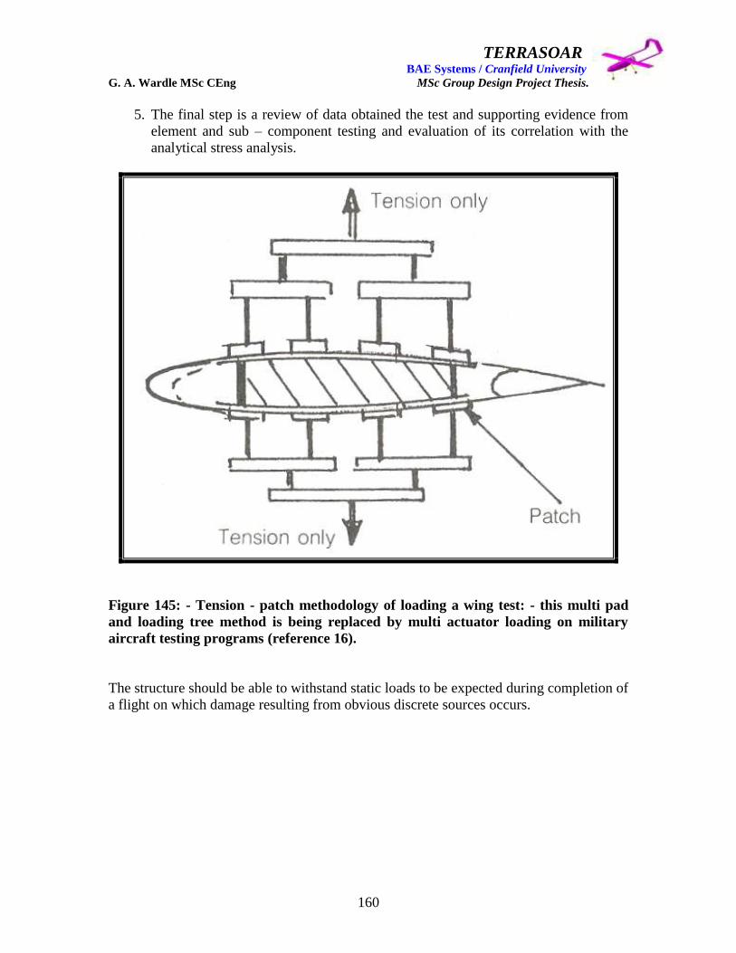
TERRASOAR BAE Systems / Cranfield University G. A. Wardle MSc CEng MSc Group Design Project Thesis.
160
5. The final step is a review of data obtained the test and supporting evidence from
element and sub – component testing and evaluation of its correlation with the
analytical stress analysis.
Figure 145: - Tension - patch methodology of loading a wing test: - this multi pad
and loading tree method is being replaced by multi actuator loading on military
aircraft testing programs (reference 16).
The structure should be able to withstand static loads to be expected during completion of
a flight on which damage resulting from obvious discrete sources occurs.

TERRASOAR BAE Systems / Cranfield University G. A. Wardle MSc CEng MSc Group Design Project Thesis.
161
Figure 146: - The loading frame method of loading the wing test article (reference
16).
Durability FST of the wing: - Cyclic Full Scale Testing of airframe structures used to
evaluate metal structures is also applied to composite structures. In general, FST cycle
testing is limited to 2 to 4 lifetimes of spectrum loading (2 for civil aircraft) in the
presence of BVID, including a spectrum load enhancement factor such as environmental
effects. Periodic inspections must occur during FST durability testing at specific intervals
between the limits of detection and the time when limits of residual strength capability
have been reached. These inspections are conducted to determine whether any damage is
progressing due to cyclic loading in order to: -
Obtain the durability performance of the structural details:
Detect any critical damage whose growth would result in failure of the test article
during the durability test.

TERRASOAR BAE Systems / Cranfield University G. A. Wardle MSc CEng MSc Group Design Project Thesis.
162
For example stiffness changes in a composite structure has been found to be an indication
of fatigue damage, hence crack and delamination (very difficult to detect) inspections are
conducted at intervals throughout the test, after a given number of cycles which would be
based on coupon, element and sub - component level testing. The inspection plan would
use the minimum detectable damage / defect size established in the materials
qualification and manufacturing development coupon, element, and sub - component test
level of the building block test program and would determine: - the frequency, and extent
of the inspections, the methods employed, intervals, inspection for zero growth, and the
residual strength associated with assumed damage. Non – Destructive Inspection
techniques likely to be employed are ultrasonic C – scan, x-ray, acoustic detection by
microphones in the structure to listen for delaminations. Finally a post – test inspection of
the test article after the FST durability test would be conducted to ensure that no damage
had occurred that would threaten the structural integrity of the composite wing box.
Damage Tolerance FST of the wing: - Testing composite FST structures for damage
tolerance is especially important because it addresses the concerns associated with both
the static and durability FST‟s. The damage tolerance test, like the static test, is a
qualification requirement to meet the Proof of Structure requirements of AMC CS
25.603, and is also required by the U.S. FAA, and military regulatory authorities. The
load specified by civil and military requirements varies )both specify a residual strength
requirement which in this case is equal to or greater than the strength required for the
specified design loads considered as the ultimate load) and requirements also vary
depending on: -
Ability to inspect damage:
Type of service inspection used:
Type of aircraft.
As in durability tests the critical flaw or damage may be associated with either its initial
state or its growth after cyclic loading. The environmental effect during the cyclic test is
not easily defined but the load enhancement of the spectrum as recommended for the
durability test would be the best option. Because the FST damage tolerance test has many
similarities to the static, and durability tests, all the testing considerations which apply to
them are also applicable to this test.
If the residual strength test is successfully passed the structure can then be loaded to
failure to further evaluate its damage tolerance capability.
The flutter proof of structure requirement would be met by sub – component testing.
The test program outlined above would meet the damage tolerance / environmental
degradation / impact evaluation requirements for military aircraft composite wing box
certification criteria.
TERRASOAR BAE Systems / Cranfield University G. A. Wardle MSc CEng MSc Group Design Project Thesis.
163
However although the above test program or something like it would be required should
BAE SYSTEMS seek to build the Terrasoar aircraft in quantity and gain unrestricted
airspace certification, for a one off aircraft flying in a sanitised range only minimal
structural proof testing would be required. This concludes the authors‟ coverage of
materials issues, manufacturing, and testing for the Terrasoar UAV.
8.0 Conclusions.
The objective of the Terrasoar project was to design, manufacture, ground test, and fly a
High Altitude Long Endurance small low cost Unmanned Air Vehicle with CAA
certification for flight at 10,000ft (3,048m) in controlled airspace, with an endurance of
5hours, and payload of 5kg, which. However these objectives were too ambitious for the
resources available to the team in terms of funding manpower and timescale.
The final solution has been to design and manufacture an aircraft which can meet a set of
more realistic missions criteria up to an altitude of 400ft (121.92m), and an endurance of
4.5hours, which was within the financial limits of the project, with the capability of being
modified with additional systems, new outboard wing, and a new engine, to fly at the
original target altitude.
The wing weight at CDR was 8.056kg and after stress maturation this grew to 11.318kg a
net gain of 3.262kg in the immediate future the material selection must be finalised so
that the final iteration of weight analysis can be undertaken based on the new detail part
sizing.
The major advances in the current wing design over that proposed by the 5th
intake are
summarised below:-
1. The fuselage to wing joint, proposals aimed at producing a robust interface joint
which could withstand the moreover, and fight loads of a much larger chord wing
than was proposed by the 5th
intake, yet facilitated the removal of the wing for
transportation to and from the test site. This involved several concepts: - The first
concept was a conventional lug and clevis design with the lugs being integral to
machined wing root ribs, these would then be slotted into „H‟ section longerons in
the fuselage and bolted into place, but although this was good in principal and is
used on the Harrier jet fighter, access for bolt insertion and securing mitigated
against this method, also in maturation the longerons were deleted. The second
concept was a hood which was to be integral to the bottom wing skin but the
complex curvature and requirement for large bend radii rendered this solution
impossible, therefore the author proposed bonding the hood to the bottom wing
skin and reinforcing this joint with bolts through the forward and aft spars. The
hood itself was to bee attached to the fuselage by quick release locks of the type
used to secure aircraft radomes. This concept was deemed to complex both to
TERRASOAR BAE Systems / Cranfield University G. A. Wardle MSc CEng MSc Group Design Project Thesis.
164
manufacture and structurally analyse. The third and final solution was a greatly
improved and more efficient interface in which joint the wing / fuselage interface
joint was been considerably simplified and relies on two sleeved bolts through the
fuel tank frames, with ample access on either of the frames to insert and secure
the bolts so that the wing could be secured for fight and removed for
transportation. The major advantages over the 5th
intake design are that the whole
wing loads are distributed along the sleeve bolts and are not point loads, and the
bolts along the chord line are in shear as the wing tries to lift off from the fuselage
and not in tension which was the case for the 5th
intake concept. Their concept
which consisted of screwing in two bolts at right angles to the chord plane into the
rear spar, and using a machined channel with integral lugs adhesively bonded to
the front spar would possibly have failed in tension both at bond interface
between the spar and the channel, and then in tension at the bolts through the rear
spar, this could not happen with the final 9th
intake joint design.
2. The inboard to outboard wing joints were another major improvement which also
had several conceptual iterations initially for two independent joints, one for the
wing interfaces and another for the boom interfaces, before the final combined
wing and boom design was selected. The first concept for a wing only interface
joint was based on ribs mounted in both the outboard and centre wing sections
have double staggered lugs for top and bottom pins which are inserted through a
cut out in the leading edge and screwed home into retained nuts mounted in the
trailing edge, and the skins extend over the interface with the outboard skin
slotting under the inboard skin to form a lap interface. A panel is then fitted over
the leading edge and secured with aero tape. This concept was however on the
scale of the Terrasoar like watch making, and the integrity of the leading edge
cover panel would be in doubt, so this concept so it was dropped. The second
concept for a wing only interface joint was to form a plug and slot interface
between ribs mounted at the ends of the torsion boxes of both outboard wing and
the centre wing, a quick release latch across the bottom tension skin of the
interface would ensure there was no risk of separation in flight. Because the top
wing surface in flight is in compression and the plug is nearly full chord a latch
across to top skin would not be required. Although this solution would have
increased the wing weight by a small margin minimum machining would have
kept this low and it could have been traded off against other areas of the structure.
This concept was loosely based on some joints the author had designed for the F-
35 Horizontal Tail test box, there was also no risk of galvanic corrosion as the
composite used in the skin and spars was glass cloth and not carbon fibre, and this
philosophy was further developed into the combined wing and boom interface
joint. Initial studies for the boom interface centred on the lug rib concept similar
to that proposed initially for the wing to fuselage joint, and subsequent to this lugs
on tabs fitted through the spar flanges had been proposed, but neither of these
were satisfactory, and a way of combining the lugged rib of the boom interface
with the wing plug and slot interface was devised. The third concept for a
combined joint was achieved by putting integral boom attachment lugs onto the
underside of the plug and slot wing interface ribs. The booms would then be
TERRASOAR BAE Systems / Cranfield University G. A. Wardle MSc CEng MSc Group Design Project Thesis.
165
slotted over lugs and pinned in place using a channel section end fitting securing
both ribs together, and making the need for a bottom skin latch un-necessary, and
this concept was carried through into the production aircraft as explained in the
bulk of this thesis. This was a much better system from both a manufacturing and
assembly view point and gave one common load path for wing bending and boom
loads, and once again the attachment bolts were in shear. The 5th
intake interface
joints were still immature when they finished the course, and resembled a
complex hook over attachment over the front spar for the boom to interface with
an attachment which was not defined, and as for the inboard to outboard wing
interface this consisted of a complex pinning arrangement which was equally
vague, and compared with this the authors combined wing and boom arrangement
has the clear advantages stated above.
3. The first concept for the flight control surface attachment using the lug and clevis
system which the author devised post PDR in which equally spaced lugs on the
aileron were pinned into clevises mechanically fastened to the rear spar using
pinned plate fitted from the inside of the rear spar so that the pins pass through the
spar web, was carried through to the Interim Maturation study prior to CDR. The
basic arrangement had limitations and was complex to assemble so a more
workable solution was required for CDR. The 5th
intakes proposal of installing
piano hinge interface attachments would not work on the revised design due to the
wing twist of 20 additionally such hinges are prone to jamming under flight
conditions. The second concept was developed after consultation with Mr Robert
Currie FCS lead and keen large radio controlled aircraft model builder which was
the philosophy of mounting the ailerons on a single continuous spigot which
considerably reduced complexity of the interface and simplified the design of the
aileron itself, and consisted of a threaded insert adhesively bonded into a hole in
the trailing edge foam, a 10mm diameter stainless steel spigot threaded at one
end, two plastic sleeves which one was to be bonded into each aileron, and spigot
receiving cup which was machined into the tip rib. With the addition of a support
lug at the mid span of the spigot in between the two ailerons this arrangement was
carried through to manufacture and unlike the 5th
intakes proposal was resistant to
jamming.
4. The structural layout of the wing and the locating of the ailerons and their
actuators in the outboard wing panels offered clear advantages over the 5th
intakes
wing in that the linkages could be more direct, i.e. no build up of excessive
backlash in the mechanism, the shorter the link, the less chance of control surface
flutter. Also the structural layout of two „C‟ section spars clamping over the front
and rear of the foam core gave the wing enhanced stiffness forming with the skin
a continuous large section filled box spar. By comparison the 5th
intake wing was
a lose collection of disassociated parts which did not act concertedly to impart
stiffness to the wing.
TERRASOAR BAE Systems / Cranfield University G. A. Wardle MSc CEng MSc Group Design Project Thesis.
166
Finally and in fairness to the 5th
intake wing designer their wing was half the chord of
that selected for the 9th
intake Terrasoar design which placed server constraints on the
location of systems and the structural layout of the wing, and the design was still at
Preliminary Design Review stage when they finished the course and many issues
remained unresolved.
The authors‟ wing design represents a full design evolution taking onboard inputs from
other team members and technical specialists in manufacture and structures to produce a
design solution which meets the operational requirements, and can be produced cost
effectively within BAE Systems, Man tech facility.
The structural test and qualification program for the wing detailed above in the main
body of the thesis is ambitious but represents a test program or something like it that
would be required should BAE SYSTEMS seek to build the Terrasoar aircraft in quantity
and gain unrestricted airspace certification.
However for a one off aircraft flying in a sanitised range only minimal structural proof
testing would be required. This concludes the authors‟ coverage of materials issues,
manufacturing, and testing for the Terrasoar UAV.
Currently the Terrasoar program is in full manufacture with completion of all major
structure scheduled for April, with final assembly and systems installation in May for a
planned first flight in July 2006.
This has been a rewarding project and the author looks forward to its successful
completion with the flight test program.
9.0 Further work required.
1. Establish a final wing skin and spar material and re-stress to give final structure
seizing:
2. Complete aileron design of the drive horn integration:
3. Complete systems integration with respect to the navigation lights:
4. Stress the ailerons and the spigot designs.
5. Proof test the as built wing:
6. Build and fly the Terrasoar aircraft.

TERRASOAR BAE Systems / Cranfield University G. A. Wardle MSc CEng MSc Group Design Project Thesis.
167
10 References
1): - UAV Certification Management, Certification / Qualification and Control of Mass /
C of G / Inertia: Mr Alan Barnes GDP thesis: Cranfield University 2006.
2): - Terrasoar Unmanned Aerial Vehicle Group Design Project Thesis: Miss Emma
Bradley GDP thesis: Cranfield University 2006.
3): - Preliminary Design Review (PDR) for “Terrasoar” High Altitude Long Endurance
Unmanned Air Vehicle: 5th
Intake PDR presentation: Cranfield University 2001.
4): - Authors private collection of Terrasoar data.
5): - AVT-0215 9th
Intake Group Design Project Frame Work document: School of
Engineering Cranfield University: March 2003.
6): - Fuselage design and integration for a High Altitude Long Endurance Aerial Vehicle
UAV: Mr Paul Francis Gilligan GDP thesis: Cranfield University 2006.
7): - Terrasoar Aerodynamic Configuration, Performance, and Design: Mr James
Pennington GDP thesis: Cranfield University 2006.
8): - Terrasoar Chief Engineer, Powerplant and Manufacturing Group Design Project: Mr
Damian Adams GDP thesis: Cranfield University 2006.
9): - Development of a Cost Effective UAV Avionics and Flight Control System: Mr
Robert Currie GDP thesis: Cranfield University 2006.
10): - Terrasoar UAV Payload, Stability and Flutter Group design Project: Miss Rachel
Cunliffe GDP thesis: Cranfield University 2006.
11): - Terrasoar Structural Analysis and Detail Stressing: Mr Robert Sneddon GDP
thesis: Cranfield University 2006.
12): - Page 16: Aircraft Conceptual Design Synthesis: Howe. D. PhD: Professional
Engineering Publishing Ltd 2000.
13): - Page 47: Attack of the Drones a History of Unmanned Aerial Combat: Yenne. B.:
Zenith Press 2004.
14): - Fundamentals of Fighter Design: Airlife Publishing Ltd 2000.
15): - Page 110: Aircraft Performance and Design: Anderson. J. D.: McGraw Hill
Publishing 1999.
TERRASOAR BAE Systems / Cranfield University G. A. Wardle MSc CEng MSc Group Design Project Thesis.
168
16): - Introduction to Aeronautics (A design perspective): Drandt. S.: Stiles. R.: Bertin. J.
J.: Whitford .R. : AIAA Education Series 1997.
17): - Aircraft Loading and Structural Layout: Professional Engineering Publishing Ltd
2004.
18): - Composite Materials for Aircraft Structures 2nd
Edition: Baker A.: AIAA
Education Series 2004.
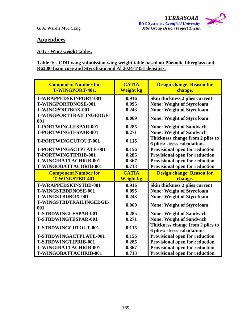
TERRASOAR BAE Systems / Cranfield University G. A. Wardle MSc CEng MSc Group Design Project Thesis.
169
Appendices
A-1: - Wing weight tables.
Table 9: - CDR wing submission wing weight table based on Phenolic fibreglass and
R63.80 foam core and Styrofoam and Al 2024-T351 densities.
Component Number for
T-WINGPORT-401.
CATIA
Weight kg
Design change: Reason for
change.
T-WRAPPEDSKINPORT-001 0.916 Skin thickness 2 plies current
T-WINGPORTDNOSE-001 0.095 None: Weight of Styrofoam
T-WINGPORTBOX-001 0.243 None: Weight of Styrofoam
T-WINGPORTTRAILINGEDGE-
001 0.069 None: Weight of Styrofoam
T-PORTWINGLESPAR-001 0.285 None: Weight of Sandwich
T-PORTWINGTESPAR-001 0.271 None: Weight of Sandwich
T-PORTWINGCUTOUT-001 0.115 Thickness change from 2 plies to
6 plies: stress calculations
T-PORTWINGACTPLATE-001 0.156 Provisional open for reduction
T-PORTWINGTIPRIB-001 0.285 Provisional open for reduction
T-WINGIBATTACHRIB-001 0.367 Provisional open for reduction
T-WINGOBATTACHRIB-001 0.713 Provisional open for reduction
Component Number for
T-WINGSTBD-401.
CATIA
Weight kg
Design change: Reason for
change.
T-WRAPPEDSKINSTBD-001 0.916 Skin thickness 2 plies current
T-WINGSTBDDNOSE-001 0.095 None: Weight of Styrofoam
T-WINGSTBDBOX-001 0.243 None: Weight of Styrofoam
T-WINGSTBDTRAILINGEDGE-
001 0.069 None: Weight of Styrofoam
T-STBDWINGLESPAR-001 0.285 None: Weight of Sandwich
T-STBDWINGTESPAR-001 0.271 None: Weight of Sandwich
T-STBDWINGCUTOUT-001 0.115 Thickness change from 2 plies to
6 plies: stress calculations
T-STBDWINGACTPLATE-001 0.156 Provisional open for reduction
T-STBDWINGTIPRIB-001 0.285 Provisional open for reduction
T-WINGIBATTACHRIB-001 0.367 Provisional open for reduction
T-WINGOBATTACHRIB-001 0.713 Provisional open for reduction

TERRASOAR BAE Systems / Cranfield University G. A. Wardle MSc CEng MSc Group Design Project Thesis.
170
Table 9 continued: -
The total wing weight after CDR for Centre box spar and foam spared wing in its
final form was = (Outboard wing weight 3.315kg x 2 = 7.030) + Centre wing weight
1.026kg = 8.056kg.
Densities Used:-
Aluminium 2024-T351 Plate = 2768kg/m3
Fibreglass = 300g/m2 = 1200kg/m
3
Styrofoam = 40kg/m3
Sandwich foam R63.80 core = 90kg/m3
These values were produced using a CATIV V5 transposed model copy of the original
CATIA V4 model, with densities in kg/m3.
Component Number for
T-WINGCENTRE-401.
CATIA
Weight kg
Design change: Reason for
change.
T-WINGCENTSKINNOSEPORT-
001 0.053
Skin thickness 4 plies plus
foam.
T-WINGCENTSKINREARPORT-
001 0.193
Skin thickness 4 plies plus
foam.
T-WINGCENTSKINNOSESTBD-
001 0.053
Skin thickness 4 plies plus
foam.
T-WINGCENTSKINREARSTBD-
001 0.193
Skin thickness 4 plies plus
foam.
T-CENTWINGBOXSPAR-001 0.534 None: Weight of Sandwich
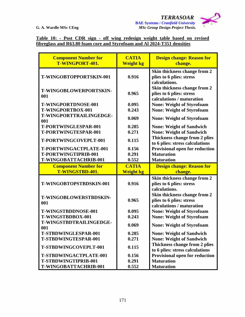
TERRASOAR BAE Systems / Cranfield University G. A. Wardle MSc CEng MSc Group Design Project Thesis.
171
Table 10: - Post CDR sign - off wing redesign weight table based on revised
fibreglass and R63.80 foam core and Styrofoam and Al 2024-T351 densities
Component Number for
T-WINGPORT-401.
CATIA
Weight kg
Design change: Reason for
change.
T-WINGOBTOPPORTSKIN-001 0.916
Skin thickness change from 2
plies to 6 plies: stress
calculations.
T-WINGOBLOWERPORTSKIN-
001 0.965
Skin thickness change from 2
plies to 6 plies: stress
calculations / maturation
T-WINGPORTDNOSE-001 0.095 None: Weight of Styrofoam
T-WINGPORTBOX-001 0.243 None: Weight of Styrofoam
T-WINGPORTTRAILINGEDGE-
001 0.069 None: Weight of Styrofoam
T-PORTWINGLESPAR-001 0.285 None: Weight of Sandwich
T-PORTWINGTESPAR-001 0.271 None: Weight of Sandwich
T-PORTWINGCOVEPLT-001 0.115 Thickness change from 2 plies
to 6 plies: stress calculations
T-PORTWINGACTPLATE-001 0.156 Provisional open for reduction
T-PORTWINGTIPRIB-001 0.291 Maturation
T-WINGOBATTACHRIB-001 0.552 Maturation
Component Number for
T-WINGSTBD-401.
CATIA
Weight kg
Design change: Reason for
change.
T-WINGOBTOPSTBDSKIN-001 0.916
Skin thickness change from 2
plies to 6 plies: stress
calculations.
T-WINGOBLOWERSTBDSKIN-
001 0.965
Skin thickness change from 2
plies to 6 plies: stress
calculations / maturation
T-WINGSTBDDNOSE-001 0.095 None: Weight of Styrofoam
T-WINGSTBDBOX-001 0.243 None: Weight of Styrofoam
T-WINGSTBDTRAILINGEDGE-
001 0.069 None: Weight of Styrofoam
T-STBDWINGLESPAR-001 0.285 None: Weight of Sandwich
T-STBDWINGTESPAR-001 0.271 None: Weight of Sandwich
T-STBDWINGCOVEPLT-001 0.115 Thickness change from 2 plies
to 6 plies: stress calculations
T-STBDWINGACTPLATE-001 0.156 Provisional open for reduction
T-STBDWINGTIPRIB-001 0.291 Maturation
T-WINGOBATTACHRIB-001 0.552 Maturation
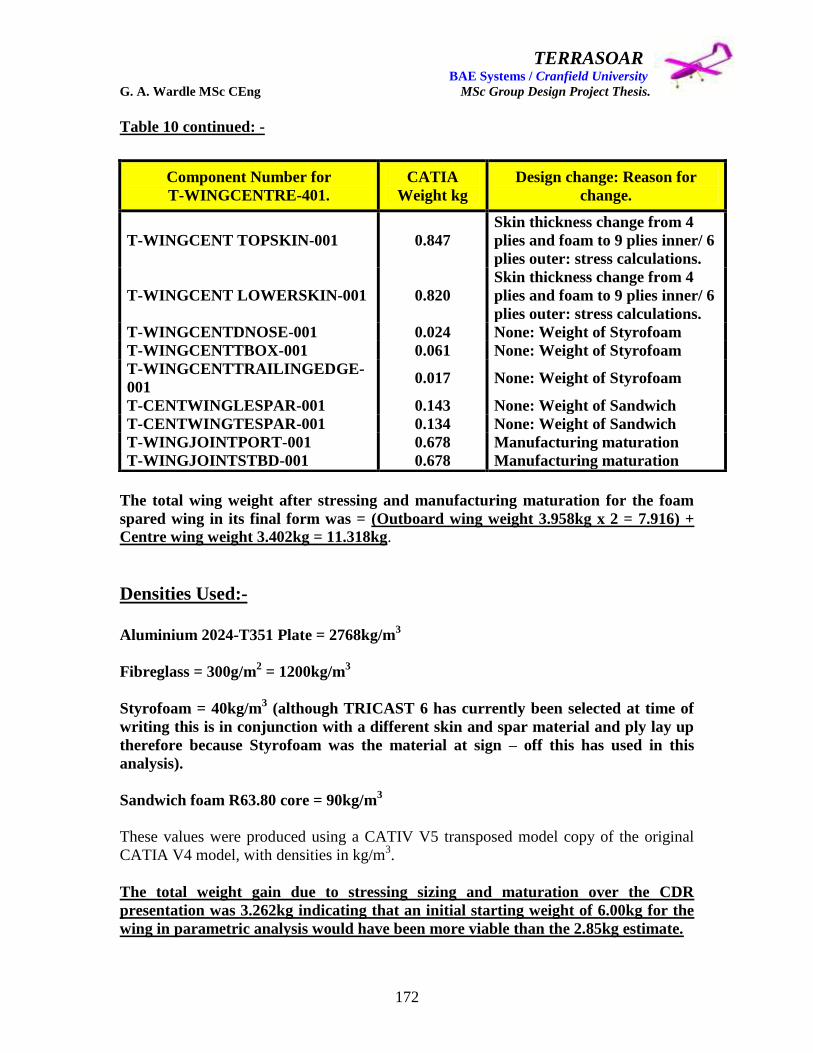
TERRASOAR BAE Systems / Cranfield University G. A. Wardle MSc CEng MSc Group Design Project Thesis.
172
Table 10 continued: -
The total wing weight after stressing and manufacturing maturation for the foam
spared wing in its final form was = (Outboard wing weight 3.958kg x 2 = 7.916) +
Centre wing weight 3.402kg = 11.318kg.
Densities Used:-
Aluminium 2024-T351 Plate = 2768kg/m
3
Fibreglass = 300g/m2 = 1200kg/m
3
Styrofoam = 40kg/m3 (although TRICAST 6 has currently been selected at time of
writing this is in conjunction with a different skin and spar material and ply lay up
therefore because Styrofoam was the material at sign – off this has used in this
analysis).
Sandwich foam R63.80 core = 90kg/m3
These values were produced using a CATIV V5 transposed model copy of the original
CATIA V4 model, with densities in kg/m3.
The total weight gain due to stressing sizing and maturation over the CDR
presentation was 3.262kg indicating that an initial starting weight of 6.00kg for the
wing in parametric analysis would have been more viable than the 2.85kg estimate.
Component Number for
T-WINGCENTRE-401.
CATIA
Weight kg
Design change: Reason for
change.
T-WINGCENT TOPSKIN-001 0.847
Skin thickness change from 4
plies and foam to 9 plies inner/ 6
plies outer: stress calculations.
T-WINGCENT LOWERSKIN-001 0.820
Skin thickness change from 4
plies and foam to 9 plies inner/ 6
plies outer: stress calculations.
T-WINGCENTDNOSE-001 0.024 None: Weight of Styrofoam
T-WINGCENTTBOX-001 0.061 None: Weight of Styrofoam
T-WINGCENTTRAILINGEDGE-
001 0.017 None: Weight of Styrofoam
T-CENTWINGLESPAR-001 0.143 None: Weight of Sandwich
T-CENTWINGTESPAR-001 0.134 None: Weight of Sandwich
T-WINGJOINTPORT-001 0.678 Manufacturing maturation
T-WINGJOINTSTBD-001 0.678 Manufacturing maturation

TERRASOAR BAE Systems / Cranfield University G. A. Wardle MSc CEng MSc Group Design Project Thesis.
173
A-2: - Major wing component sketch book for part identification.
T-WINGOBTIPRIB-001/-002
T-WINGOBTOPSKIN-001/-002

TERRASOAR BAE Systems / Cranfield University G. A. Wardle MSc CEng MSc Group Design Project Thesis.
174
T-WINGOBLOWERSKIN-001/-002
T-WINGOBDNOSE-001/-002

TERRASOAR BAE Systems / Cranfield University G. A. Wardle MSc CEng MSc Group Design Project Thesis.
175
T-WINGOBLESPAR-001/-002
T-WINGOBTESPAR-001/-002

TERRASOAR BAE Systems / Cranfield University G. A. Wardle MSc CEng MSc Group Design Project Thesis.
176
T-WINGOBTIPCORE-001/-002
T-WINGOBMAINCORE-001/-002
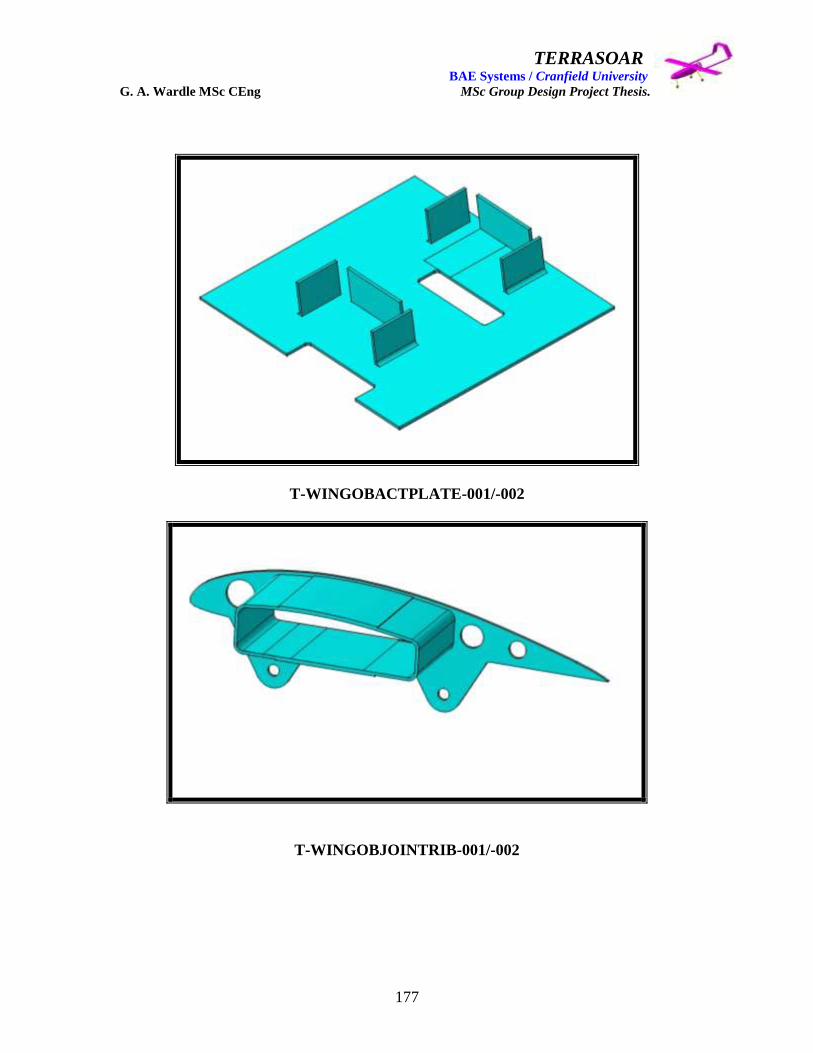
TERRASOAR BAE Systems / Cranfield University G. A. Wardle MSc CEng MSc Group Design Project Thesis.
177
T-WINGOBACTPLATE-001/-002
T-WINGOBJOINTRIB-001/-002

TERRASOAR BAE Systems / Cranfield University G. A. Wardle MSc CEng MSc Group Design Project Thesis.
178
T-WINGOBACTCOVER-001/-002
T-WINGOBTE-001/-002

TERRASOAR BAE Systems / Cranfield University G. A. Wardle MSc CEng MSc Group Design Project Thesis.
179
T-WINGCTJOINTRIB-001/-002
T-WINGCTTOPSKIN-001

TERRASOAR BAE Systems / Cranfield University G. A. Wardle MSc CEng MSc Group Design Project Thesis.
180
T-WINGCTLOWERSKIN-001
T-WINGCTDNOSE-001/-002
- 001
- 002

TERRASOAR BAE Systems / Cranfield University G. A. Wardle MSc CEng MSc Group Design Project Thesis.
181
T-WINGCTTE-001/-002
T-WINGCTLESPAR-001
- 002
- 001

TERRASOAR BAE Systems / Cranfield University G. A. Wardle MSc CEng MSc Group Design Project Thesis.
182
T-WINGTESPAR-001
T-WINGCTCORE-001
Due to the current material changes the author deemed the generation of a drawing set as
inappropriate to this thesis as the drawings would be out of date when the thesis was read
therefore the current F-35(JSF) policy has been adopted by producing the above sketch
book of all major structural wing components for identification sizing can be obtained
from interrogation of the Cranfield University solid model in the Terrasoar data pack NB
-001 is a PORT component -002 is a STARBOAD component, Blue = Aluminium, Green
= Glass cloth: Yellow = Foam.

TERRASOAR BAE Systems / Cranfield University G. A. Wardle MSc CEng MSc Group Design Project Thesis.
183
A-3 Wing sign-off document.
TERRASOAR DEMONSTRATION AIRCRAFT
AIRFRAME STRUCTURE SIGN – OFF DOCUMENT
MAJOR AIRFRAME COMPONENT: - WING
Prepared for: - BAE SYSTEMS
Cranfield University
Prepared by: - G. Wardle.
Airframe Lead.
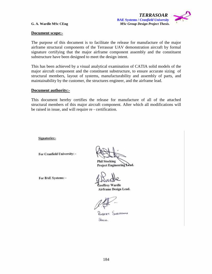
TERRASOAR BAE Systems / Cranfield University G. A. Wardle MSc CEng MSc Group Design Project Thesis.
184
Document scope:-
The purpose of this document is to facilitate the release for manufacture of the major
airframe structural components of the Terrasoar UAV demonstration aircraft by formal
signature certifying that the major airframe component assembly and the constituent
substructure have been designed to meet the design intent.
This has been achieved by a visual analytical examination of CATIA solid models of the
major aircraft component and the constituent substructure, to ensure accurate sizing of
structural members, layout of systems, manufacturability and assembly of parts, and
maintainability by the customer, the structures engineer, and the airframe lead.
Document authority:-
This document hereby certifies the release for manufacture of all of the attached
structural members of this major aircraft component. After which all modifications will
be raised in issue, and will require re - certification.

TERRASOAR BAE Systems / Cranfield University G. A. Wardle MSc CEng MSc Group Design Project Thesis.
185
Majo
r U
nit
WIN
GT
-WIN
G-8
01
Terr
asoar
Assem
bly
Cen
tre S
ecti
on
T-W
ING
CE
NT
RE
-401
AT
WIN
GW
ing
Deta
ilG
lass C
loth
T-C
AT
-001
AT
WIN
GC
entr
e S
ection
Deta
ilR
esin
T-C
AT
-002
AT
WIN
GC
entr
e S
ection
Su
b A
ssem
bly
Fo
rward
Win
g S
EC
TIO
NT
-WIN
GB
OX
FW
DS
PA
R-4
01
AT
WIN
GC
en
tre S
ecti
on
Deta
ilS
leeves
T-W
ING
SLE
EV
E-0
01
AT
WIN
GC
entr
e S
ection
Deta
ilS
leeves
T-W
ING
SLE
EV
E-0
01
AT
WIN
GC
entr
e S
ection
Deta
ilS
kin
Port
T-W
ING
SK
INU
PP
ER
-001
A428.0
7361.9
450.6
7T
WIN
GC
entr
e S
ection
Deta
ilS
kin
Sta
rboard
T-W
ING
SK
INU
PP
ER
-001
A428.0
7361.9
450.6
7T
WIN
GC
entr
e S
ection
Su
b A
ssem
bly
Aft
Win
g B
ox S
par
T-W
ING
BO
XA
FT
SP
AR
-401
AT
WIN
GC
en
tre S
ecti
on
Deta
ilW
ing B
ox F
oam
Core
T-W
ING
BO
XC
OR
E-0
01
A914.2
5158.7
146.9
5T
WIN
GC
entr
e S
ection
Deta
ilP
ort
Rib
T-W
ING
CE
NT
RE
RIB
-001
A103.0
0361.9
4101.7
0T
WIN
GC
entr
e S
ection
Deta
ilS
tarb
oard
Rib
T-W
ING
CE
NT
RE
RIB
-001
A103.0
0361.9
4101.7
0T
WIN
GC
entr
e S
ection
Deta
ilP
ort
Win
g B
ox D
-Nose
T-P
OR
TW
ING
BO
XD
NO
SE
-001
A410.5
663.4
042.7
4T
WIN
GC
entr
e S
ection
Deta
ilS
tarb
oard
Win
g B
ox D
-Nose
T-S
TB
WIN
GB
OX
DN
OS
E-0
01
A410.5
663.4
042.7
4T
WIN
GC
entr
e S
ection
Deta
ilP
ort
Tra
ilin
g E
dge F
oam
Core
T-P
OR
TT
EF
OA
M-0
01
A428.0
7124.8
433.1
0T
WIN
GC
entr
e S
ection
Deta
ilS
tarb
oard
Tra
ilin
g E
dge F
oam
Core
T-S
TB
TE
FO
AM
-001
A428.0
7124.8
433.1
0T
WIN
GC
entr
e S
ection
Deta
ilLeadin
g E
dge C
Spar
T-C
EN
TW
ING
LE
CS
PA
R-0
01
A1127.2
540.0
047.1
0T
WIN
GS
tarb
oard
Outb
oard
Win
g
Deta
ilT
railin
g E
dge C
Spar
T-P
OR
TW
ING
TE
CS
PA
R-0
01
A1127.2
540.0
042.7
0T
WIN
GP
ort
Outb
oard
Win
g
Assem
bly
Po
rt O
utb
oard
Win
g S
ecti
on
T-W
ING
PO
RT
-401
AT
WIN
GW
ing
Deta
ilG
lass C
loth
T-C
AT
-001
AT
WIN
GP
ort
Outb
oard
Win
g
Deta
ilR
esin
T-C
AT
-002
AT
WIN
GP
ort
Outb
oard
Win
g
Deta
ilS
kin
O
UT
BD
Port
T-W
ING
SK
IN-0
01
A1240.8
7361.9
450.6
7T
WIN
G P
ort
Outb
oard
Win
g
Deta
ilD
nose leadin
g e
dge
T-W
ING
PO
RT
DN
OS
E-0
01
A1234.8
765.0
442.5
7T
WIN
GP
ort
Outb
oard
Win
g
Deta
ilP
ort
Win
g b
ox F
oam
section
T-W
ING
PO
RT
BO
X-0
01
A1216.8
7158.7
146.9
5T
WIN
GP
ort
Outb
oard
Win
g
Deta
ilP
ort
Win
g T
railin
g E
dge F
oam
T-W
ING
PO
RT
TR
AIL
ING
ED
GE
-001
A705.3
7126.3
335.7
7T
WIN
GP
ort
Outb
oard
Win
g
Deta
ilLeadin
g E
dge C
Spar
T-P
OR
TW
ING
LE
CS
PA
R-0
01
A1234.8
740.0
047.1
0T
WIN
GS
tarb
oard
Outb
oard
Win
g
Deta
ilT
railin
g E
dge C
Spar
T-P
OR
TW
ING
TE
CS
PA
R-0
01
A1234.8
740.0
042.7
0T
WIN
GP
ort
Outb
oard
Win
g
Deta
ilA
ctu
ato
r cut out cover
T-P
OR
TW
ING
CU
TO
UT
-001
A145.3
586.3
41.5
0T
WIN
GP
ort
Outb
oard
Win
g
Deta
ilR
ear
Spar
attachm
ent lu
gs (
4)
T-P
OR
TW
ING
LU
GS
-001
AN
/AN
/AN
/AT
WIN
GP
ort
Outb
oard
Win
g
Deta
ilA
ilero
n a
ssem
bly
pin
T-P
OR
TW
ING
PIN
-001
AT
WIN
GP
ort
Outb
oard
Win
g
Deta
ilA
ilero
n a
ttachm
ent lu
gs
T-W
ING
AIL
ER
ON
LU
GS
-001
AT
WIN
GP
ort
Outb
oard
Win
g
Deta
ilB
ushes
T-P
OR
TW
ING
BU
SH
-001
AT
WIN
GP
ort
Outb
oard
Win
g
Deta
ilW
ing A
ttachm
ent R
ibT
-PO
RT
WIN
GA
TT
RIB
-001
A103.0
0361.9
4101.7
0T
WIN
GP
ort
Outb
oard
Win
g
Deta
ilP
ort
Tip
Rib
T-P
OR
TW
ING
TIP
RIB
-001
A26.5
0361.9
450.6
7T
WIN
GP
ort
Outb
oard
Win
g
Deta
ilA
ctu
ato
r M
ounting P
late
T
-PO
RT
WIN
GA
CT
PLA
TE
-001
A145.3
5174.6
71.5
0T
WIN
GP
ort
Outb
oard
Win
g
Deta
ilA
ctu
ato
rs (
2)
T-C
AT
-019
AT
WIN
GP
ort
Outb
oard
Win
g
Deta
ilA
ctu
ato
r C
ontr
ol R
ods (
2)
T-C
AT
-020
AT
WIN
GP
ort
Outb
oard
Win
g
Deta
ilA
ilero
n A
ttachm
ent pin
T-A
LE
AT
PIN
-001
AT
WIN
GS
tarb
oard
Outb
oard
Win
g
Su
b A
ssem
bly
Ailero
ns (
2)
T-P
OR
TW
ING
AIL
ER
ON
-401
AT
WIN
GP
ort
Outb
oard
Win
g
Deta
ilA
ilero
n Inte
rnal P
late
T-A
LE
INP
LA
TE
-001
AT
WIN
GP
ort
Outb
oard
Win
g

TERRASOAR BAE Systems / Cranfield University G. A. Wardle MSc CEng MSc Group Design Project Thesis.
186
T-P
OR
TW
ING
AIL
ER
ON
SP
AR
-001
AN
/AN
/AN
/AT
WIN
GA
ilero
ns
Geoff
Ward
le
T-P
OR
TW
ING
AIL
ER
ON
CO
RE
-001
AT
WIN
GA
ilero
ns
Geoff
Ward
le
T-C
AT
-001
AT
WIN
GA
ilero
ns
Geoff
Ward
le
T-C
AT
-002
AT
WIN
GA
ilero
ns
Geoff
Ward
le
T-P
OR
TW
ING
AIL
ER
ON
SE
ALS
-001
AN
/AN
/AN
/AT
WIN
GA
ilero
ns
Geoff
Ward
le
T-C
AT
-021
AT
WIN
GP
ort
Outb
oard
Win
gR
ob C
urr
ie
T-0
02-F
CS
LO
OM
AT
WIN
GP
ort
Outb
oard
Win
gR
ob C
urr
ie
T-0
02-E
LE
CLO
OM
AT
WIN
GP
ort
Outb
oard
Win
gR
ob C
urr
ie
T-A
CT
BA
YF
RA
ME
-001
AT
WIN
GP
ort
Outb
oard
Win
gG
eoff
Ward
le
T-A
CT
BA
YF
RA
ME
-001
AT
BD
TD
BT
BD
TW
ING
Port
Outb
oard
Win
gG
eoff
Ward
le
T-W
ING
ST
BD
-401
AT
WIN
GW
ing
Geoff
Ward
le
T-C
AT
-001
AT
WIN
GS
tarb
oard
Outb
oard
Win
gG
eoff
Ward
le
T-C
AT
-002
AT
WIN
GS
tarb
oard
Outb
oard
Win
gG
eoff
Ward
le
T-W
ING
SK
IN-0
01
A1240.8
7361.9
450.6
7T
WIN
GS
tarb
oard
Outb
oard
Win
gG
eoff
Ward
le
T-W
ING
PO
RT
DN
OS
E-0
01
A1234.8
765.0
442.5
7T
WIN
GS
tarb
oard
Outb
oard
Win
gG
eoff
Ward
le
T-W
ING
PO
RT
BO
X-0
01
A1216.8
7158.7
146.9
5T
WIN
GS
tarb
oard
Outb
oard
Win
gG
eoff
Ward
le
T-W
ING
PO
RT
TR
AIL
ING
ED
GE
-001
A705.3
7126.3
335.7
7T
WIN
GS
tarb
oard
Outb
oard
Win
gG
eoff
Ward
le
T-S
TB
WIN
GLE
CS
PA
R-0
01
A1234.8
740.0
047.1
0T
WIN
GS
tarb
oard
Outb
oard
Win
gG
eoff
Ward
le
T-S
TB
WIN
GT
EC
SP
AR
-001
A1234.8
740.0
042.7
0T
WIN
GS
tarb
oard
Outb
oard
Win
gG
eoff
Ward
le
T-P
OR
TW
ING
CU
TO
UT
-001
A145.3
586.3
41.5
0T
WIN
GS
tarb
oard
Outb
oard
Win
gG
eoff
Ward
le
T-P
OR
TW
ING
LU
GS
-001
AN
/AN
/AN
/AT
WIN
GS
tarb
oard
Outb
oard
Win
gG
eoff
Ward
le
T-P
OR
TW
ING
PIN
S-0
01
AN
/AN
/AN
/AT
WIN
GS
tarb
oard
Outb
oard
Win
gG
eoff
Ward
le
T-W
ING
AIL
ER
ON
LU
G-0
01
AT
WIN
GS
tarb
oard
Outb
oard
Win
gG
eoff
Ward
le
T-P
OR
TW
ING
BU
SH
-001
AT
WIN
GS
tarb
oard
Outb
oard
Win
gG
eoff
Ward
le
T-P
OR
TW
ING
AT
TR
IB-0
01
A103.0
0361.9
4101.7
0T
WIN
GS
tarb
oard
Outb
oard
Win
gG
eoff
Ward
le
T-P
OR
TW
ING
TIP
RIB
-001
A26.5
0361.9
450.6
7T
WIN
GS
tarb
oard
Outb
oard
Win
gG
eoff
Ward
le
T-P
OR
TW
ING
AC
TP
LA
TE
-001
A145.3
5174.6
71.5
0T
WIN
GS
tarb
oard
Outb
oard
Win
gG
eoff
Ward
le
T-C
AT
-022
AT
WIN
GS
tarb
oard
Outb
oard
Win
gG
eoff
Ward
le
T-C
AT
-023
AT
WIN
GS
tarb
oard
Outb
oard
Win
gG
eoff
Ward
le
T-A
LE
AT
PIN
-001
AT
WIN
GS
tarb
oard
Outb
oard
Win
gG
eoff
Ward
le
T-P
OR
TW
ING
AIL
ER
ON
-401
AT
WIN
GS
tarb
oard
Outb
oard
Win
gG
eoff
Ward
le
T-A
LE
INP
LA
TE
-001
AT
WIN
GP
ort
Outb
oard
Win
gG
eoff
Ward
le
T-P
OR
TW
ING
AIL
ER
ON
CO
RE
-001
AT
WIN
GA
ilero
ns
Geoff
Ward
le
T-C
AT
-001
AT
WIN
GA
ilero
ns
Geoff
Ward
le
T-C
AT
-002
AT
WIN
GA
ilero
ns
Geoff
Ward
le
T-P
OR
TW
ING
AIL
ER
ON
SE
ALS
-001
AN
/AN
/AN
/AT
WIN
GA
ilero
ns
Geoff
Ward
le
T-C
AT
-024
AT
WIN
GS
tarb
oard
Outb
oard
Win
gG
eoff
Ward
le
T-0
02-F
CS
LO
OM
AT
WIN
GS
tarb
oard
Outb
oard
Win
gG
eoff
Ward
le
T-0
02-E
LE
CLO
OM
AT
WIN
GS
tarb
oard
Outb
oard
Win
gG
eoff
Ward
le
T-A
CT
BA
YF
RA
ME
-001
AT
BD
TB
DT
BD
TW
ING
Sta
rboard
Outb
oard
Win
gG
eoff
Ward
le
TERRASOAR BAE Systems / Cranfield University G. A. Wardle MSc CEng MSc Group Design Project Thesis.
187
A-4 Wing drawing pack.
TERRASOAR WING MAJOR COMPONENT
DIMENSIONED DRAWINGS.
Contents: - 2-D drawings for all metallic parts, and dimensioned isometric
drawings for all composite and foam parts, for the complete wing.