Terminology / Acronyms: The following ter STEP 6: Place a phone call. 1. 2. 3… · 2019-07-01 ·...
2
INTRODUCTION This Quick Start Guide (QSG) provides instructions for initial start-up of the Thales MissionLINK ™ system up to and including making a basic phone call and accessing the Internet. This QSG is only for use on Thales MissionLINK ™ systems that have been successfully installed per the Installation guide (Document # 84465). After initial start-up, for more detailed operational procedures, reference the Thales MissionLINK ™ User Manual (Document # 84468) located on the Thales website and also accessible through the Thales MissionLINK ™ Management Portal. This document contains technology controlled for export by the U.S. Department of Commerce in accordance with Export Administration Regulations. Diversion contrary to U.S. law prohibited. Terminology / Acronyms: The following terminology is used throughout this QSG. BAA: Broadband Active Antenna SIM: Subscriber Identity Module TU: Terminal Unit VoIP: Voice over Internet Protocol PoE: Power over Ethernet WAN: Wide Area Network POTS: Plain Old Telephone Service Wi-Fi: Wireless Network GETTING STARTED STEP 1: Connect Phone (standard POTS handset) or Ethernet VoIP Phone to TU. The TU front has a main power switch, one RJ-14 jack for POTS, three PoE RJ-45 connections for VoIP phones or Computers, and one WAN connection port. TU Front Panel Detail POTS Phone connection By default the POTS phone(s) are pre-configured to use the Iridium voice lines without any additional configuration. The TU can accept up to 2 POTS phones (with RJ-14 Splitter). VoIP (or Thales SureLINK IP Handset) Phone connection By default, the TU has (3) extensions preconfigured for use with POTS phones, VoIP phones, or Thales IP handsets as shown in the table below. If using a VoIP phone, Thales recommends CISCO SPA504G and Grand Stream GXP2140 models for ease of use with Thales MissionLINK ™ . Other brands and models may work but have not been tested by Thales. Follow your VoIP phone configuration guide to connect using the following parameters. From the factory, the defaults for the three phone lines are shown below: Extension 1: (make and receive calls on line 1 of your SIM) User: "1001" Password: "1001" Host: "sip.thaleslink" Protocol: udp Extension 2: (will make and receive calls on line 2 of your SIM) User: "1002" Password: "1002" Host: "sip.thaleslink" Protocol: udp Extension 3: (will make and receive calls on line 3 of your SIM) User: "1003" Password: "1003" Host: "sip.thaleslink" Protocol: udp By default, Extensions 1 and 2 are mapped to POTS phone connections and Extension 3 is flexible. A VoIP phone can be configured to any extension, even those assigned to the POTS lines. The Thales SureLINK IP Handset will have a default of 1001 or extension 1, so that will automatically work the same as the first POTS line. 3 STEP 6: Place a phone call. 1. Choose either POTS or VoIP handset. 2. Remove the handset from the base and ensure a dial tone is present. 3. For all calls using the Iridium Voice Services, dial 9 before the number. When making a local call, simply dial the extension. 4. Call a known number to test call and voice clarity Call the Iridium automated message: (9) 1-480-752-5105 Note: The MissionLINK ™ system contains PBX functionality, where both local calls and outside calls can be made. Local extensions can be dialed directly from another local phone, but outside calls require dialing a “9” in order to connect to an outside line prior to dialing the phone number. STEP 7: Access the internet. Once your device has successfully connected to the TU, open the Management Portal http://portal.thaleslink to verify the satellite connection. Verify: • No active alerts (DASHBOARD or ALERTS page on the Management Portal) • Satellites detected (go to STATUS SERVICE), signal strength bars (top right of screen) should show more than 1 bar as available. • Check that the antenna has a clear view of the sky or the alerts if voice or data calls fail. Try loading a small website such as www.google.com to verify your internet connection. If the page loads successfully you are ready to browse the internet. THALES MANAGEMENT PORTAL When you first log into the Thales Management Portal, you will notice menu choices down the left hand side of the screen. Each of these menu options are discussed in more detail in the Thales MissionLINK ™ User Manual. Status – Provides status of each of the Devices, GPS, LAN, Phones, Services, and the SIM card. Alerts – Provides a listing of system alerts Calls – Provides information relating to Calls, including current calls, call history, and call management. Distress – This section is where you send a distress signal. Settings – This section is where the administrator can set operating parameters/ settings for sending messages, using Wi-Fi, WAN, LAN, Satellite, data, and phone. System – This section allows the operator to perform system backups, view data usage, reset the system, and view/update system firmware. Diagnostics – The section enables the administrator to run self-test, check system status, and view diagnostics logs entries. About – Provides system level information for the antenna, modem, power supply, system, VoIP Module, and Wi-Fi Help – Provides a link to the Thales MissionLINK ™ User Documentation, Installation Instructions, and Quick Start Guide. Thales Defense & Security, Inc. 22605 Gateway Center Drive | Clarksburg MD 20871 Toll-Free 1.800.324.6089 | Phone: 240.864.7000 | Fax: 240.864.7920 Email: [email protected] | Website: www.thalesdsi.com PN 3402174-1 Rev B Thales MissionLINK ™ Quick Start Guide
Transcript of Terminology / Acronyms: The following ter STEP 6: Place a phone call. 1. 2. 3… · 2019-07-01 ·...

INTRODUCTION This Quick Start Guide (QSG) provides instructions for initial start-up of the Thales MissionLINK™ system up to and including making a basic phone call and accessing the Internet. This QSG is only for use on Thales MissionLINK™ systems that have been successfully installed per the Installation guide (Document # 84465). After initial start-up, for more detailed operational procedures, reference the Thales MissionLINK™ User Manual (Document # 84468) located on the Thales website and also accessible through the Thales MissionLINK™ Management Portal. This document contains technology controlled for export by the U.S. Department of Commerce in
accordance with Export Administration Regulations. Diversion contrary to U.S. law prohibited.
Terminology / Acronyms: The following terminology is used throughout this QSG.
BAA: Broadband Active Antenna SIM: Subscriber Identity Module
TU: Terminal Unit VoIP: Voice over Internet Protocol
PoE: Power over Ethernet WAN: Wide Area Network
POTS: Plain Old Telephone Service Wi-Fi: Wireless Network
GETTING STARTED
STEP 1: Connect Phone (standard POTS handset) or Ethernet VoIP Phone to TU. The TU front has a main power switch, one RJ-14 jack for POTS, three PoE RJ-45 connections for VoIP phones or Computers, and one WAN connection port.
TU Front Panel Detail POTS Phone connection By default the POTS phone(s) are pre-configured to use the Iridium voice lines without any additional configuration. The TU can accept up to 2 POTS phones (with RJ-14 Splitter). VoIP (or Thales SureLINK IP Handset) Phone connection By default, the TU has (3) extensions preconfigured for use with POTS phones, VoIP phones, or Thales IP handsets as shown in the table below. If using a VoIP phone, Thales recommends CISCO SPA504G and Grand Stream GXP2140 models for ease of use with Thales MissionLINK™. Other brands and models may work but have not been tested by Thales. Follow your VoIP phone configuration guide to connect using the following parameters. From the factory, the defaults for the three phone lines are shown below:
Extension 1: (make and receive calls on line 1 of your SIM)
User: "1001" Password: "1001" Host: "sip.thaleslink" Protocol: udp
Extension 2: (will make and receive calls on line 2 of your SIM)
User: "1002" Password: "1002" Host: "sip.thaleslink" Protocol: udp
Extension 3: (will make and receive calls on line 3 of your SIM)
User: "1003" Password: "1003" Host: "sip.thaleslink" Protocol: udp
By default, Extensions 1 and 2 are mapped to POTS phone connections and Extension 3 is flexible. A VoIP phone can be configured to any extension, even those assigned to the POTS lines. The Thales SureLINK IP Handset will have a default of 1001 or extension 1, so that will automatically work the same as the first POTS line.
3
STEP 6: Place a phone call. 1. Choose either POTS or VoIP handset. 2. Remove the handset from the base and ensure a dial tone is present. 3. For all calls using the Iridium Voice Services, dial 9 before the number. When making a
local call, simply dial the extension. 4. Call a known number to test call and voice clarity
Call the Iridium automated message: (9) 1-480-752-5105
Note: The MissionLINK™ system contains PBX functionality, where both local calls and outside calls can be made. Local extensions can be dialed directly from another local phone, but outside calls require dialing a “9” in order to connect to an outside line prior to dialing the phone number.
STEP 7: Access the internet. Once your device has successfully connected to the TU, open the Management Portal http://portal.thaleslink to verify the satellite connection.
Verify: • No active alerts (DASHBOARD or ALERTS page on the Management Portal) • Satellites detected (go to STATUS SERVICE), signal strength bars (top right of screen)
should show more than 1 bar as available. • Check that the antenna has a clear view of the sky or the alerts if voice or data calls fail. Try loading a small website such as www.google.com to verify your internet connection. If the page loads successfully you are ready to browse the internet.
THALES MANAGEMENT PORTAL
When you first log into the Thales Management Portal, you will notice menu choices down the left hand side of the screen. Each of these menu options are discussed in more detail in the Thales MissionLINK™ User Manual.
Status – Provides status of each of the Devices, GPS, LAN, Phones, Services, and the SIM card.
Alerts – Provides a listing of system alerts
Calls – Provides information relating to Calls, including current calls, call history, and call management.
Distress – This section is where you send a distress signal.
Settings – This section is where the administrator can set operating parameters/ settings for sending messages, using Wi-Fi, WAN, LAN, Satellite, data, and phone.
System – This section allows the operator to perform system backups, view data usage, reset the system, and view/update system firmware.
Diagnostics – The section enables the administrator to run self-test, check system status, and view diagnostics logs entries.
About – Provides system level information for the antenna, modem, power supply,
system, VoIP Module, and Wi-Fi
Help – Provides a link to the Thales MissionLINK™ User Documentation, Installation
Instructions, and Quick Start Guide.
Thales Defense & Security, Inc. 22605 Gateway Center Drive | Clarksburg MD 20871
Toll-Free 1.800.324.6089 | Phone: 240.864.7000 | Fax: 240.864.7920 Email: [email protected] | Website: www.thalesdsi.com
PN 3402174-1 Rev B
Thales MissionLINK™ Quick Start Guide
This document contains technology controlled for export by the U.S. Department of
Commerce in accordance with Export Administration Regulations. Diversion contrary to
U.S. law prohibited.
IMPORTANT: DOWNLOAD INSTRUCTIONS MANUALS NOW
Power cable (not shown)
Wi-Fi Antenna(included)
Terminal Unit (TU)
10ft Ethernet cable (included)
Power Button
1. Open outer carton, remove Terminal Unit (TU), DC Power Cable, and Ethernet Cable (or
Wi-Fi antenna). 2. Connect TU to a 10-32VDC power source, turn on TU and wait for System LED to go solid.
(Note: System ( ) and/or Satellite ( ) LEDs may be red since the antenna is not connected.)
3. Once the System LED is solid and not blinking, the Management Portal can be accessed to download the manuals.
4. Connect a PC to LAN port shown with Ethernet cable (optional – use Wi-Fi antenna). 5. Select “ThalesLINK” in network settings (either W-Fi or LAN settings page). 6. Open a web browser, Type: http://portal.thaleslink (Do not type .com or any other
extension). Note: If there is a problem connecting, try http://portal.thaleslink/# 7. Select Help Tab on the left side of screen. 8. Download User Manual, Installation Manual and Quick Start Guide. 9. Turn TU off, disconnect peripherals and proceed with installation manual instructions.
SYSTEM OVERVIEW
Thales MissionLINK™ typical system components are:
A. Terminal Unit (TU) B. Broadband Active Antenna (BAA) C. Cables D. SIM Card (From Iridium Air Time Provider) E. POTS Phone (not included) F. VoIP Phone(s) (not included) G. Advanced setups may have Cellular Modem or network connected (not included) H. Laptop/PC (not included)
2
STEP 2: Know your Thales MissionLINK™ It may be necessary to know details about your Thales MissionLINK™ system when calling for help or service. IMEI is unique to each unit and can be found on the back plate of the TU. This IMEI can also be found in the http://portal.thaleslink under the ABOUT tab. IMSI is a unique identifier to each SIM card. This IMSI can also be found in the http://portal.thaleslink under the STATUS SIM tabs. (SIM must be inserted)
Thales MissionLINK™ IMEI and IMSI from mobile device
STEP 3: Install SIM Remove SIM Cover.
Install SIM card from Air-time provider as below. Insert card with contacts down as shown until it clicks into place. Be sure to engage the lock for the SIM Card and secure the SIM Cover once the SIM Card has been locked into place.
Installing SIM card and engaging the lock
STEP 4: Power the Thales MissionLINK™ unit. Before powering the unit, make sure the DC power cable is connected to a 10-32VDC source, the polarity is correct, and the DC cable is securely connected to the TU. The antenna must also be connected per the installation manual. Power the unit by pressing and releasing the power button on the TU (see Figure on page 3). NOTE: After the button is pressed and released, a few seconds will pass before the System LED (left) starts flashing. It may take a few minutes on initial startup for all 3 LEDs on the unit top to turn solid GREEN or BLUE.
System, Satellite and Wi-Fi Status LED’s 4
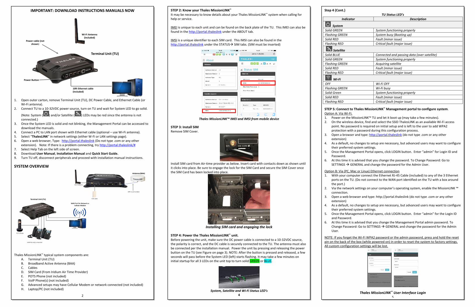
Step 4 (Cont.) TU Status LED’s
Indicator Description
System
Solid GREEN System functioning properly
Flashing GREEN System busy (Booting up)
Solid RED Fault (minor issue)
Flashing RED Critical fault (major issue)
Satellite
Solid BLUE Connected and passing data (over satellite)
Solid GREEN System functioning properly
Flashing GREEN Acquiring satellite
Solid RED Fault (minor issue)
Flashing RED Critical fault (major issue)
Wi-Fi
OFF Wi-Fi OFF
Flashing GREEN Wi-Fi busy
Solid Green System functioning properly
Solid RED Fault (minor issue)
Flashing RED Critical fault (major issue)
STEP 5: Connect to Thales MissionLINK™ Management portal to configure system. Option A: Via Wi-Fi. 1. Power on the MissionLINK™ TU and let it boot up (may take a few minutes). 2. On the wireless device, find and select the SSID ThalesLINK as an available Wi-Fi access
point. No password is required on initial setup and is left to the user to add WPA2 protection with a password during this configuration process.
3. Open a browser and type: http://portal.thaleslink (do not type .com or any other extension)
4. As a default, no changes to setup are necessary, but advanced users may want to configure their preferred system settings.
5. Once the Management Portal opens, click LOGIN button. Enter “admin” for Login ID and Password.
6. At this time it is advised that you change the password. To Change Password: Go to SETTINGS GENERAL and change the password for the Admin User.
Option B: Via (PC, Mac or Linux) Ethernet connection 1. With your computer connect the Ethernet RJ-45 Cable (included) to any of the 3 Ethernet
ports on the TU. (Do not connect to the WAN port identified on the TU with a box around the port.)
2. Via the network settings on your computer’s operating system, enable the MissionLINK ™ connection.
3. Open a web browser and type: http://portal.thaleslink (do not type .com or any other extension)
4. As a default, no changes to setup are necessary, but advanced users may want to configure their preferred system settings.
5. Once the Management Portal opens, click LOGIN button. Enter “admin” for the Login ID and Password.
6. At this time it is advised that you change the Management Portal admin password. To Change Password: Go to SETTINGS GENERAL and change the password for the Admin User.
NOTE: If you forget the Wi-Fi WPA2 password or the admin password, press and hold the reset pin on the back of the box (while powered on) in order to reset the system to factory settings. All custom configuration settings will be lost.
Thales MissionLINK™ User Interface Login 5