Terminal Sanitary Utility Study - Milwaukee County
66
Terminal Sanitary Utility Study For General Mitchell International Airport Prepared for: Milwaukee County Department of Transportation And Public Works Milwaukee Wisconsin Prepared by: Kapur & Associates, Inc. 7711 North Port Washington Road Milwaukee, Wisconsin 53217 In Association with PSJ Engineering, Inc. 7665 N Port Washington Rd Milwaukee, Wisconsin 53217 June 2012
Transcript of Terminal Sanitary Utility Study - Milwaukee County

Terminal Sanitary Utility Study
For
General Mitchell International Airport
Prepared for:
Milwaukee County Department of Transportation And Public Works
Milwaukee Wisconsin
Prepared by:
Kapur & Associates, Inc. 7711 North Port Washington Road
Milwaukee, Wisconsin 53217
In Association with PSJ Engineering, Inc.
7665 N Port Washington Rd Milwaukee, Wisconsin 53217
June 2012

TABLE OF CONTENTS Executive Summary ................................................................................................. 1 1.0 Background ........................................................................................................................ 3 2.0 Work Performed ................................................................................................................ 4 3.0 Sanitary Sewer System Fixture Inventory ......................................................................... 7 4.0 Sanitary Sewage Ejectors and Sumps ................................................................................ 9 5.0 Inspection of Manhole, Grease Traps, Pump Stations, and Restaurant Spaces ............... 11 6.0 Water Usage and Waste Water Discharge Based on Fixture Counts .............................. 12 7.0 Identify Bottlenecks in Sanitary Sewer System .............................................................. 14 8.0 Qualitative Spot Check of Sanitary Flows at Select Manholes ....................................... 16 9.0 Recommended Sanitary Sewer System Improvements ................................................... 17 Tables Table ES-1 – Recommended Improvements ...................................................................................1 Table 1 – Sanitary Sewer Fixture Summary By Brach ....................................................................7 Table 2 – Sewage Ejector Summary ................................................................................................9 Table 3 – Sanitary Sewer Load vs. Capacity .................................................................................12 Table 4 - Sanitary Collection System Bottlenecks ........................................................................14 Table 5 – Recommended Sanitary Sewer Improvements ..............................................................18 Table 6- Recommended Grease Trap Improvements ....................................................................20 Figures Figure ES-1 - Locations of Recommended Improvements. .............................................................2 Figure 1 – Sanitary Sewer Fixture Inventory ...................................................................................8 Figure 2 – Sewage Ejector Locations ............................................................................................10 Figure 3 – Sanitary Sewer Load vs. Capacity ................................................................................13 Figure 4 – Sanitary Collection System Bottleneck Locations .......................................................15 Figure 5 – Locations of Recommended Improvements .................................................................19 Figure 6 – Locations of Recommended Grease Trap Improvements ............................................21 Appendix Appendix A: Reviewed Drawing List Appendix B: Complete Fixture Inventory by Room Number Appendix C: Detailed Summary of Sewage Ejectors Appendix D: Restaurant Fixtures Appendix E: Water and Wastewater Usage Appendix F: Spot Check Flow Monitoring Appendix G: Cost Estimates

Terminal Sanitary Utility Study for GMIA Milwaukee County Dept. of Transportation & Public Works
1
Executive Summary The General Mitchell International Airport (GMIA) Sanitary Sewer Evaluation Study of the sanitary sewer collection system, as detailed in the RFP dated April 22, 2010, has been completed. The purpose of the study was to analyze the GMIA sanitary sewer collection system and recommend solutions for resolving the deficiencies that currently plague the system. The following recommended improvements are presented below: Table ES-1 – Recommended Improvements
Recommended Improvement Cost 1. Replace sewage ejector (Ejector #16) with new grinder pump
system west end of Concourse D. $64,231
2. Replace the under-sized 6-inch piping between Manhole 290-280335 and Ejector #9 with 20 feet of 8-inch pipe.
$3,794
3. Replace pneumatic pump (Ejector #9) with new pneumatic pump system (Two (2) 250 GPM pumps) serving south end of baggage claim.
$144,723
4. Replace the under-sized 6-inch piping between Service Entry (Map ID 9) and the pneumatic pump (Ejector #9) with 330 feet of 10-inch pipe
$58,097
5. Replace the under-sized 6-inch line between Ejector #16 and manhole 290-280334 with 20 feet of 8-inch pipe.
$37,017
6. Replace 7 Grease Interceptors $77,500 Total Estimated Project Cost $385,362
Figure ES-1 shows the locations of these recommended improvements.

!!2
!!2
!!2
!!2!!2
!!2
!!2
!!2
!!2
!!2!!2
!!2
!!2!!2
!!2
!!2
!!2
!!2
!!2 !!2
!!2
!!2
!!2
!!2
!!2
[Ú
!!2
!!2
!!2
i
i
i
i
i
iii
i
i
i
i
GF
GF
GF
GFGF
GF
GFGF
GF
GF
GF
GF
GF
GF
GF
GF
C245, Chili's
D224, Noona's
D242, Usinger's
C201A, Pizza Hut
M278B, Brew Haus
M239A, Northpoint
M268, Famiglia's Pizza
E210, Cooler by the Lake
Clean-out
Clean-out
290280338A
290-280401
290-280340
290-280334
290-280324 290-280327
290-280328
290-280330
290-280331
290-280343
290-280336
290-280335
290-280338
290-280326
290-280342
290-280341
290-280332
290-280333
290-280347
290-280345
290-280346
290-280337A
290-280329 Flow Monitoring
290-280339 Flow Monitoring
Ejector 3
Ejector 2
Ejector 6
Ejector 8Ejector 4
Ejector 7 Ejector 5
Ejector 1
Ejector 16
Ejector 12
Ejector 13
Ejector 10
Ejector 15
Ejector 11
Ejector 14
Ejector 9
GMIA Sanitary Sewer SystemGreaseTrap_ImprovementsPipe Improvements
GF Sewage_Ejectors
i GreaseTrapsManholes_SanitaryLiftStn
!!2 <Null>[Ú Lift Station
Pipes_SanitaryBranchLoc
11, 523456Other
I 210Feet
1 inch = 167 feet
#4
#2#3
#1
#5
#6
#6
#6
#6
#6
#6
#6
#6
dave_m
Text Box
Figure ES-1: Locations of Recommended Improvements

Terminal Sanitary Utility Study for GMIA Milwaukee County Dept. of Transportation & Public Works
3
1.0 Background Over the past several years the existing sanitary sewer collection system in the GMIA has experienced overloading and grease related issues causing portions of the system to be shut down for emergency maintenance. As the number of restaurants within the terminal has grown, demands have been placed on the system that it was not designed to meet. As a result, the system suffers from recurrent pipe clogging and overflows. Maintenance personnel indicate that several of the sewage ejectors have reduced capacities due to the buildup of grease in the pump chambers. In September of 2010 the Airport commissioned Kapur and Associates Inc.; in association with PSJ Engineering, Inc., to review, identify deficiencies, and provide recommendations to improve the overall performance of the sanitary sewer system. Site system investigations were performed to verify record drawings and plans provided by the Airport Engineering Staff. This report summarizes the findings of this investigation and recommends improvements. This study included the preparation of a Geographic Information System (GIS) of the sanitary sewer system based upon GMIA record drawings, field investigations, and existing GIS data.

Terminal Sanitary Utility Study for GMIA Milwaukee County Dept. of Transportation & Public Works
4
2.0 Work Performed The following narrative identifies tasks performed during this investigation as specified in the original scope of services.
1. Reviewed Record Drawings:
Digital files and paper copies of the sanitary collection system were provided by the GMIA
Engineering Department. These documents were reviewed to obtain an initial overview of the present system configuration. The complete list of reviewed documents during this investigation is provided in Appendix A. The reviewed data included:
a. Forty-nine (49) digital engineering files were reviewed covering the following areas:
Concourse C Stem and Hammerhead Concourse D Security Checkpoint and Stem Main Terminal
b. One-hundred-seven (107) paper engineering drawings were reviewed covering the following areas:
FAA Weather Office in the Administration Building Main Terminal Midwest Airlines Concourse D Remodel, Apron Office and Plumbing
Upgrades Various drawings covering the main terminal and each concourse
2. Met with Airport Staff:
A kick-off meeting and several follow up sessions were conducted to exchange information, align expectations and provide a venue for project feedback.
a. Kick-Off Meeting, 1/20/2011
Attendees: Ed Baisch – GMIA Engineering; Bob Wagner – PSJ Engineering; Dave Misun – Kapur; Terry Blue – GMIA Deputy Director, O&M; Christopher Lucas – GMIA Maintenance Manager; John Moore – GMIA Landside Operations Manager; Jerry Peterson – GMIA HVAC Maintenance Supervisor Items Discussed:
Need for a restaurant fixture count Implement best practice solutions to resolve deficiencies Pneumatic sewage ejector in basement of Main Terminal – Severe
grease issues

Terminal Sanitary Utility Study for GMIA Milwaukee County Dept. of Transportation & Public Works
5
D-Stem Lift Station – Signs of grease build-up Recently increased E Concourse Lift Station capacity Some floor drains eliminated in ground floor bag rooms Demand spikes: Arriving flights – toilets, departing flights –
restaurants Increase in aircraft waste being discharged into collection system Evidence of clear flows in some segments
b. Meeting with GMIA Plumbing Staff, 3/23/2011 Attendees: Jim G. – GMIA Staff Plumber; Bob Wagner – PSJ Engineering, Dave Misun - Kapur Items Discussed:
Sewage Ejectors D-Stem (North) and Hammerhead E-Concourse @ N End of Line Lower Level Baggage Claim
c. GIS Meetings Conclusions Attendees: Timothy Pearson – GMIA GIS Specialist; Ed Baisch – GMIA Engineering; Tom Wagner & Dave Misun – Kapur Items Discussed:
CAD drawings of entire sanitary collection system available, will incorporate into the GIS
Floor plans available in database format compatible with proposed GIS
3. Update sewer plans:
Relevant engineering drawings were updated based upon information obtained from field visits and interviews with GMIA Plumbing Department staff.
a. Updated sewer system plan provided by GMIA to reflect field observations. The
digital file is in an AutoCAD DWG format and will be included on the CD containing the GIS data.
4. Setup GIS system for sanitary sewer system:
A GIS of the sanitary collection structures was created from the data supplied by the GMIA Engineering Department and updated with information collected during field visits. The geodatabase includes:

Terminal Sanitary Utility Study for GMIA Milwaukee County Dept. of Transportation & Public Works
6
a. Environmental Systems Research Incorporated (ESRI) Geodatabase Format
b. ESRI is compatible with existing GMIA GIS
c. The GIS data produced for this project is viewable with various versions of ESRI software, including a free application called ArcReader. GMIA already has a GIS in place and this new data will be available using any of the methods currently employed by the airport staff. The data will be delivered in an ESRI shapefile format incorporated on a CD.
5. Identify and inventory wastewater fixtures:
Grease traps and sewage pumps were field located and the make, model number, and capacity were recorded where available. Sanitary manholes were inspected on an as-needed basis. Wastewater fixtures such as toilets, sinks, showers, pumps, etc., were identified on the engineering drawings and field verified.
a. Kapur & PSJ staff conducted field visits to GMIA on the following dates:
3/15/2011 & 3/16/2011 3/23/2011 4/2011 Additional visits by PSJ Staff
b. Sinks and toilets comprise the dominant class by number of fixtures in the airport terminal complex. These fixtures were identified on the engineering drawings and field-verified. Showers, mop basins, and grease traps were counted in the field. The make, model number, and other sewage ejector information/relevant data were collected where available.

Terminal Sanitary Utility Study for GMIA Milwaukee County Dept. of Transportation & Public Works
7
3.0 Sanitary Sewer System Fixture Inventory The sanitary sewer system in the terminal area of GMIA consists of six different branches, numbered 1 through 6 for the purpose of this study. Table 1 presented below lists the total number of fixtures identified on the engineering drawings and/or during the field review. The complete fixture inventory by room number is listed in Appendices B. See Figure 1 for branch locations.
Table 1 – Sanitary Sewer Fixture Summary By Brach
Branch Location Toilets Sinks Urinals ShowersMop
Basins Dishwashers
Grease Traps
1 Concourse E/S End of Main Terminal
70 94 22 5 3 5 4
2 Concourse D/N End of Main Terminal
89 110 28 3 2 3 4
3 Concourse C Stem/ Hammerhead
54 68 17 2 1 1 3
4 Administration Building
16 13 6 4 -- -- --
5 Corporate Aviation Facilities
5 6 3 -- -- -- --
6 International Arrivals Building
10 9 5 1 -- -- --
TOTAL 244 300 81 15 6 9 11

!!2
!!2
!!2
!!2!!2
!!2
!!2
!!2
!!2
!!2!!2
!!2
!!2 !!2
!!2
!!2
!!2
!!2
!!2!!2
!!2!!2
!!2
!!2
!!2
[Ú
!!2
!!2
!!2
"?B
"?B
"?B
"?B
"?B
I*
I*I*I*I*
I*
I*I*
I*I*I*I*
I*I*
I*I*I*
I*I*I*I*
I*I*
I*I*I*I*
I*I* I*I*
I*I*I*I*
I*I*
I*I*
I*I*I*
I* I*
I*
I*I*
I*I*
I*I*
I*
I*I*I*I*I*
I*I*
I*
I*I*
I*I*I*
I*I*I*
I*I*
I*I*
I*I*
I*I*
I*I*
I*I*I*I*I*I*
I*I*
I*I*
I* I*I* I*I*I*
I*
I*I*
I*I*
I*
I*I*
I*
I*I*
I*
I*
Þ
Þ
Þ
ÞÞ
ÞÞÞÞ
Þ
ÞÞ
ÞÞÞÞÞ
Þ
Þ
ÞÞÞ Þ
ÞÞ
Þ
ÞÞ
Þ
Þ
Þ
Þ
ÞÞ
Þ ÞÞ
ÞÞ
Þ
Þ
Þ
ÞÞ
ÞÞÞÞ
Þ
Þ
Þ
ÞÞ
Þ
Clean-out
Clean-out
290280338A
290-280401
290-280340
290-280334
290-280324 290-280327
290-280328
290-280330
290-280331
290-280343
290-280336
290-280335
290-280338
290-280323
290-280325
290-280326
290-280342
290-280341
290-280332
290-280347
290-280345
290-280346
290-280337A
290-280329 Flow Monitoring
290-280339 Flow Monitoring
GMIA Sanitary Sewer SystemI* BathroomsÞ Sinks_Basins_Fountains"?B Inlets
Manholes_SanitaryLiftStn
!!2 <Null>[Ú Lift Station
Pipes_SanitaryBranchLoc
11, 523456Other
I 250Feet
1 inch = 200 feet
dave_m
Text Box
Figure 1: Fixture Inventory

Terminal Sanitary Utility Study for GMIA Milwaukee County Dept. of Transportation & Public Works
9
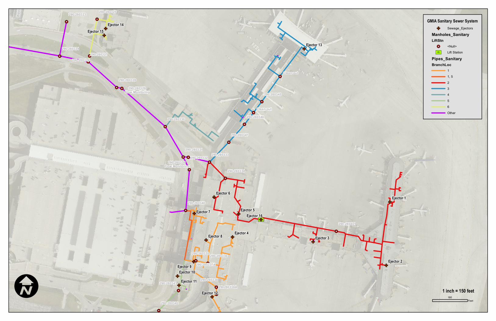
4.0 Sanitary Sewage Ejectors and Sumps Figure 2 shows the location of the existing terminal ejectors. Table 2 summarizes the location, size, make/model, etc. for each ejector. Appendix C provides more specific details for each ejector such as serial number, room number, horse power, etc.
Table 2 – Sewage Ejector Summary Ejector
ID Location
Branch Location
Description
1 D174A, D Concourse 2 3-inch Weil, Private Owner, 1 HP 2 D122B, D Concourse 2 3-inch ABS Sanitary Sump, Private Owner 3 D106, D Concourse 2 2-inch Weil (Noona's), 2-inch to 4-inch run 4 Room 38 1 4-inch Weil, Kitchen Sewage Ejector
5 NE end of tug tunnel 2 4-inch Weil Vertical Sewage, 2.5-Inch Solids, Model 2224
6 NW end of tug tunnel 2 4-inch Weil Vertical Sewage, 2.5-Inch Solids, Model 2224
7 Adjacent to Room 56A 1 4-inch Weil Vertical Sewage, 2.5-Inch Solids, Model 2224
8 SW end of tug tunnel 1 4-inch Weil Vertical Sewage, 2.5-Inch Solids, Model 2224
9 Baggage Claim Building Lower Level, Adjacent to Room 84B
1 Pneumatic Ejector - Dual
10 Room 73 (N End) 5 4-inch Weil Submersible Sump, 2 HP 11 Room 73 (S End) 5 4-inch Weil Submersible Sump, 2 HP
12 Under walkway @ N end of E Concourse
1 4-inch Weil Submersible Sump, 2 HP
13 C151A, C Concourse 3 Dual 3-inch Weil w/ grinder vanes 14, 15 IAB Basement 6 2-inch Sanitary, 1.5-inch Storm; Weil
16 D-Stem Lift Station 2 Dual 4-inch BJM Pumps, 5 HP
!!2
!!2
!!2
!!2
!!2
!!2
!!2
!!2
!!2
!!2!!2
!!2
!!2!!2
!!2
!!2
!!2
!!2 !!2
!!2
!!2
!!2
!!2
!!2
[Ú
!!2
!!2
!!2
GF
GF
GF
GFGF
GF
GFGF
GF
GF
GF
GF
GF
GF
GF
GF
Clean-out
Clean-out
290280338A
290-280401
290-280340
290-280334
290-280324 290-280327
290-280328
290-280330
290-280331
290-280336
290-280335
290-280338
290-280323
290-280325
290-280326
290-280342
290-280341
290-280332
290-280333
290-280347
290-280345
290-280346
290-280337A
290-280329 Flow Monitoring
290-280339 Flow Monitoring
Ejector 3
Ejector 2
Ejector 6
Ejector 8 Ejector 4
Ejector 7 Ejector 5
Ejector 9
Ejector 1
Ejector 16
Ejector 12
Ejector 13
Ejector 10
Ejector 15
Ejector 11
Ejector 14 GMIA Sanitary Sewer SystemGF Sewage_Ejectors
Manholes_SanitaryLiftStn
!!2 <Null>[Ú Lift Station
Pipes_SanitaryBranchLoc
11, 523456Other
I 180Feet
1 inch = 150 feet
dave_m
Text Box
Figure 2: Sewage Ejector Locations

Terminal Sanitary Utility Study for GMIA Milwaukee County Dept. of Transportation & Public Works
11
5.0 Inspection of Manhole, Grease Traps, Pump Stations, and Restaurant Spaces
The food service locations in the Main Terminal and each concourse were visited to observe fixture layout and note any issues that might result in the discharge of grease or unsuitable material into the collection system. Results are listed in Appendix-D. The accumulation of grease in sewage ejector #16 and pneumatic pump system (ejector #9) is a major operational and maintenance issue, especially with the system serving the D Concourse. Even though all the restaurants/food serving areas have grease interceptors installed near dishwashing equipment and sinks, food-related grease is still entering the sanitary collection system. In April 2011, the 6-inch sanitary sewer line that serves the south area of the Main Terminal (concourse level) experienced an overflow event and upon inspection, was found to be packed with grease along its entire length. Several restaurants are located in the space served by the line; the overflow negatively impacted the ticketing area on the ground floor level.
The location and maintenance of the grease traps in some of the leased areas that offer food service appears to be sub-optimal. The in-floor grease trap at The Brew Haus, located in the Main Terminal, appears to not have been serviced/maintained on a regular basis. The cover is bolted down and covered with debris that appears to have been in place for quite some time. The trap at Famiglia's Pizza, also in the Main Terminal, is decrepit, contains no identifying marks or tags, and does not appear to have been replaced when the leased space was remodeled for the new tenant.
The set of pneumatic ejectors located in the lower level of the Baggage Claim Building (Ejector #9) and the lift station located at the north side of the Concourse D-Stem adjacent to the Main Terminal (Ejector #16), handle the majority of the solids loads. The entire D Concourse discharges through this Lift Station and the pneumatic pump receives waste from the entire E Concourse and the south half of the Main Terminal. Signs of grease build-up are present in the lift station chambers, as well as in the chambers of each pump at the pneumatic ejector. The level sensors in this pneumatic sewage ejector have been modified in an attempt to maintain capacity. According the Plumbing Staff, the discharge line from the ejector shows no sign of build-up, thus upstream from the inlet is where mitigation strategies should be implemented.
Concourse D also contains two privately owned sewage ejectors located on the north and south ends of the Concourse D extensions referred to by airport staff as the Hammerhead. The north one serves Frontier Airlines (Ejector #1) and is where the aircraft holding tank contents are discharged into the sanitary collection system. The other ejector serves Southwest Airlines (Ejector #2) and performs the same function at the north location. These locations do not appear to have grease related issues in normal operation, but work procedures must be monitored to ensure that unsuitable objects are not discharged into the collection system. Sanitary ejector locations are referenced on Figure 2.

Terminal Sanitary Utility Study for GMIA Milwaukee County Dept. of Transportation & Public Works
12
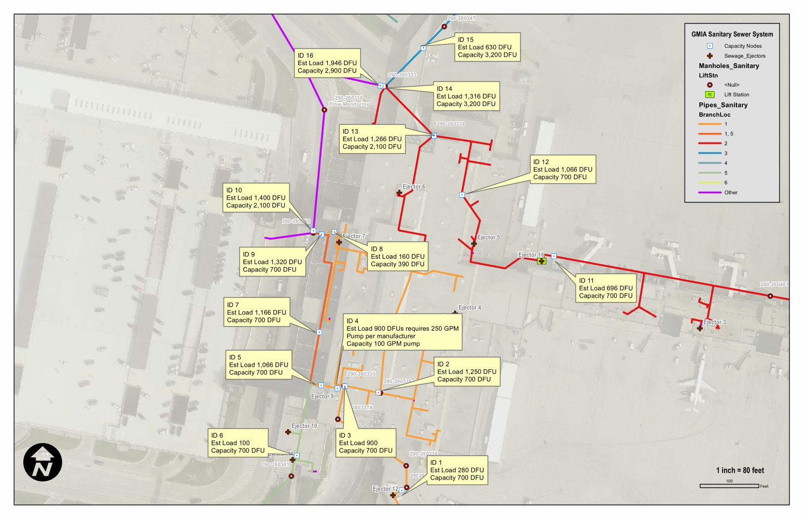
6.0 Water Usage and Waste Water Discharge Based on Fixture Counts Once the fixture inventory was completed, each fixture’s contribution to the overall system load was calculated. For this sewer system analysis, the use of the Department of Commerce’s standard Drainage Fixture Unit (DFU) was utilized. A curve of pipe capacity based upon pipe diameter and slope is provided in Appendix E. Table 3 summarizes the estimated sanitary flow and pipe capacities for each pipe (ID) location. Figure 3 references the locations of each ID. A detailed description and report of water usage and waste water discharge is provided in Appendix E. Table 3 – Sanitary Sewer Load vs. Capacity
MAP ID ESTIMATED LOAD
(DFU) EXISTING PIPE SIZE
CAPACITY OF PIPE (DFU)
1 280 6 700 2 1,250 6 700 3 900 6 700
4 900 DFUs Requires 250 GPM pump, per
manufacturer
Pneumatic Pumps
100 GPM
5 1,066 6 700 6 100 6 700 7 1,166 6 700 8 160 5 390 9* 1,320 6 700 10 1,400 10 2,100 11 696 6 700 12 1,066 6 700 13 1,266 8 2,100 14 1,316 10 3,200 15 630 10 3,200 16 1,946 10 3,200
* Pipe is being replaced as part of a separate GMIA project.
!!2
!!2
!!2
!!2
!!2
!!2
!!2!!2
!!2
!!2
!!2
!!2
!!2
[Ú
!!2
GF
GFGF
GF
GF
GF
GF
GF
GF
GF
GF
ÍÖ
ÍÖÍÖÍÖ
ÍÖ
ÍÖ
ÍÖ
ÍÖÍÖÍÖ
ÍÖ
ÍÖ
ÍÖ
ÍÖ
ÍÖ
ÍÖ
290280338A
290-280401
290-280340
290-280334
290-280331
290-280336
290-280335
290-280338 290-280341
290-280332 290-280333
290-280347
290-280337A
290-280339 Flow Monitoring
Ejector 3
Ejector 6
Ejector 8Ejector 4
Ejector 7 Ejector 5
Ejector 9
Ejector 16
Ejector 12
Ejector 10
Ejector 11
GMIA Sanitary Sewer SystemÍÖ Capacity NodesGF Sewage_Ejectors
Manholes_SanitaryLiftStn
!!2 <Null>[Ú Lift Station
Pipes_SanitaryBranchLoc
11, 523456Other
I 100Feet
1 inch = 80 feet
ID 15Est Load 630 DFUCapacity 3,200 DFUID 16
Est Load 1,946 DFUCapacity 2,900 DFU
ID 14Est Load 1,316 DFUCapacity 3,200 DFU
ID 13Est Load 1,266 DFUCapacity 2,100 DFU
ID 12Est Load 1,066 DFUCapacity 700 DFU
ID 10Est Load 1,400 DFUCapacity 2,100 DFU
ID 9Est Load 1,320 DFUCapacity 700 DFU
ID 8Est Load 160 DFUCapacity 390 DFU
ID 7Est Load 1,166 DFUCapacity 700 DFU
ID 5Est Load 1,066 DFUCapacity 700 DFU
ID 4Est Load 900 DFUs requires 250 GPMPump per manufacturerCapacity 100 GPM pump
ID 3Est Load 900Capacity 700 DFU
ID 2Est Load 1,250 DFUCapacity 700 DFU
ID 6Est Load 100Capacity 700 DFU
ID 1Est Load 280 DFUCapacity 700 DFU
ID 11Est Load 696 DFUCapacity 700 DFU
dave_m
Text Box
Figure 3: Sanitary Sewer Load vs. Capacity

Terminal Sanitary Utility Study for GMIA Milwaukee County Dept. of Transportation & Public Works
14
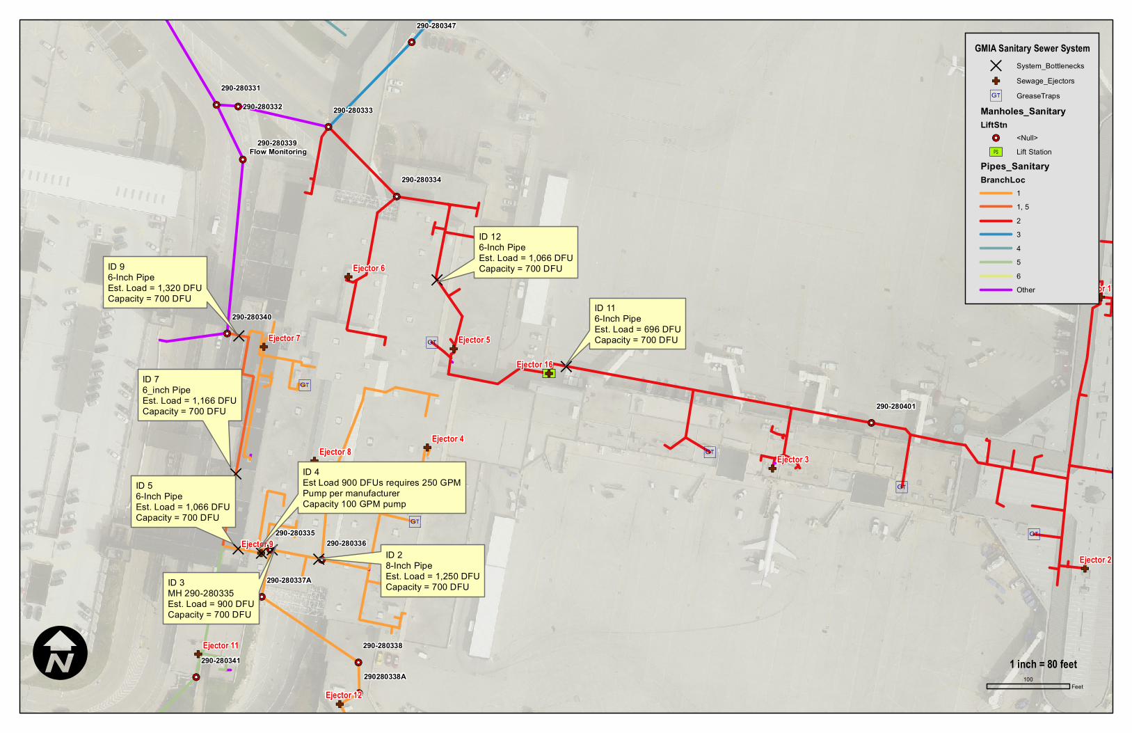
7.0 Identify Bottlenecks in Sanitary Sewer System Areas where the collection system load exceeds capacity were identified. Capacity upgrades for these areas were developed and discussed in section 9.0. Table 4 summarizes the bottlenecks (locations where pipe capacities are exceed). Figure 4 identifies the locations of the bottlenecks.
Table 4 - Sanitary Collection System Bottlenecks
MAP ID ESTIMATED LOAD
(DFU) EXISTING PIPE SIZE
CAPACITY OF PIPE (DFU)
2 1,250 6 700 3 900 6 700
4 900 DFUs Requires 250 GPM pump, per
manufacturer
Pneumatic Pumps
100
5 1,066 6 700 7 1,166 6 700 9* 1,320 6 700 12 1,066 6 700
* Pipe is being replaced as part of a separate GMIA project.
!!2
!!2
!!2
!!2
!!2
!!2
!!2!!2
!!2
!!2
!!2
!!2
!!2
[Ú
!!2
i
i
i
i
i
ii
i
GF
GF
GFGF
GF
GF
GF
GF
GF
GF
GF
GF
GF
DDDD
D
D
D
D
290280338A
290-280401
290-280340
290-280334
290-280331
290-280336
290-280335
290-280338 290-280341
290-280332 290-280333
290-280347
290-280337A
290-280339 Flow Monitoring
Ejector 3
Ejector 2
Ejector 6
Ejector 8 Ejector 4
Ejector 7 Ejector 5
Ejector 9
Ejector 1
Ejector 16
Ejector 12
Ejector 10
Ejector 11
GMIA Sanitary Sewer SystemD System_BottlenecksGF Sewage_Ejectors
i GreaseTrapsManholes_SanitaryLiftStn
!!2 <Null>[Ú Lift Station
Pipes_SanitaryBranchLoc
11, 523456Other
I 100Feet
1 inch = 80 feet
ID 28-Inch PipeEst. Load = 1,250 DFUCapacity = 700 DFUID 3
MH 290-280335Est. Load = 900 DFUCapacity = 700 DFU
ID 4Est Load 900 DFUs requires 250 GPMPump per manufacturerCapacity 100 GPM pump
ID 56-Inch PipeEst. Load = 1,066 DFUCapacity = 700 DFU
ID 76_inch PipeEst. Load = 1,166 DFUCapacity = 700 DFU
ID 96-Inch PipeEst. Load = 1,320 DFUCapacity = 700 DFU
ID 116-Inch PipeEst. Load = 696 DFUCapacity = 700 DFU
ID 126-Inch PipeEst. Load = 1,066 DFUCapacity = 700 DFU
dave_m
Text Box
Figure 4: System Bottlenecks

Terminal Sanitary Utility Study for GMIA Milwaukee County Dept. of Transportation & Public Works
16
8.0 Qualitative Spot Check of Sanitary Flows at Select Manholes Flow measurements were checked at select manholes to verify the loading values calculated from the fixture counts. Sanitary flow monitoring identified the maximum depth of sanitary flow to be less than half of the pipe diameter. The exterior sanitary sewer, namely the 15” line, is not the cause of backups based upon field verification (spot checking sanitary flows). Spot check Flow Monitoring data is summarized in Appendix F.
Terminal Sanitary Utility Study for GMIA Milwaukee County Dept. of Transportation & Public Works
17
9.0 Recommended Sanitary Sewer System Improvements Recommended system improvements and cost estimates were identified to guide the allocation of capital resources for improvements to the collection system moving forward. Detailed cost estimates are provided in Appendix G.
The sanitary sewer lines that are recommended for upgrade are proposed to be replaced in place; conflict with other utilities or structures should be minimal. Table 5 details recommended improvements, including cost. Figure 5 identifies the locations of recommended improvements.

Terminal Sanitary Utility Study for GMIA Milwaukee County Dept. of Transportation & Public Works
18
Table 5 – Recommended Sanitary Sewer Improvements Map ID
Description EstimatedLength (LF)
Comments Cost
1
Replace sewage ejector (Ejector #16) with new grinder pump system west end of Concourse D.
N/A
Requires wet well to be deepened and new maintenance friendly duplex grinder pump system with interlock to other parallel pumping systems. Temporary pumping to be provided during installation.
$64,231
2
Replace the under-sized 6-inch piping between Manhole 290-280335 and Ejector #9 with 20 feet of 8-inch pipe.
20
Requires open cut through roadway and curb in tug tunnel.
$3,794
3
Replace pneumatic pump (Ejector #9) with new pneumatic pump system (Two (2) 250 GPM pumps) serving south end of baggage claim.
NA
Requires temporary pumping during installation.
$144,723
4
Replace the under-sized 6-inch piping between Service Entry (Map ID 9) and the pneumatic pump (Ejector #9) with 330 feet of 10-inch pipe.
330
Accessible and has already bridged the luggage conveyor. Check valve located between two pumps to prevent cross-flow and the upgraded pipe capacity (6-inch to 10-inch) should be sufficient to handle any discharge even if both are operating simultaneously. Can electrically lock out non-pumping station when other station is pumping, then let non-pumping station pump down $36,300
5
Replace the under-sized 6-inch line between Ejector #16 and manhole 290-280334 with 20 feet of 8-inch pipe.
20
Runs mostly through office areas. Section to Lift Station will require open cut through tug tunnel roadway and curb.
$2,200
6 Replace 7 Grease Interceptors
NA $77,500
TOTAL ESTIMATED PROJECT COST $385,362

!!2
!!2
!!2
!!2!!2
!!2
!!2
!!2
!!2
!!2!!2
!!2
!!2!!2
!!2
!!2
!!2
!!2
!!2 !!2
!!2
!!2
!!2
!!2
!!2
[Ú
!!2
!!2
!!2
i
i
i
i
i
iii
i
i
i
i
GF
GF
GF
GFGF
GF
GFGF
GF
GF
GF
GF
GF
GF
GF
GF
C245, Chili's
D224, Noona's
D242, Usinger's
C201A, Pizza Hut
M278B, Brew Haus
M239A, Northpoint
M268, Famiglia's Pizza
E210, Cooler by the Lake
Clean-out
Clean-out
290280338A
290-280401
290-280340
290-280334
290-280324 290-280327
290-280328
290-280330
290-280331
290-280343
290-280336
290-280335
290-280338
290-280326
290-280342
290-280341
290-280332
290-280333
290-280347
290-280345
290-280346
290-280337A
290-280329 Flow Monitoring
290-280339 Flow Monitoring
Ejector 3
Ejector 2
Ejector 6
Ejector 8Ejector 4
Ejector 7 Ejector 5
Ejector 1
Ejector 16
Ejector 12
Ejector 13
Ejector 10
Ejector 15
Ejector 11
Ejector 14
Ejector 9
GMIA Sanitary Sewer SystemGreaseTrap_ImprovementsPipe Improvements
GF Sewage_Ejectors
i GreaseTrapsManholes_SanitaryLiftStn
!!2 <Null>[Ú Lift Station
Pipes_SanitaryBranchLoc
11, 523456Other
I 210Feet
1 inch = 167 feet
#4
#2#3
#1
#5
#6
#6
#6
#6
#6
#6
#6
#6
dave_m
Text Box
Figure 5: Locations of Recommended Improvements

Terminal Sanitary Utility Study for GMIA Milwaukee County Dept. of Transportation & Public Works
20
Grease Traps and Interceptors The installation of larger grease interceptor units is recommended, sized for the entire kitchen load, at the end of the restaurant waste line and upstream of its connection to the sanitary waste line. At this point in the waste stream no restroom fixtures would be involved. All of the grease traps inspected for this project were connected too close to the fixtures being served and did not have sufficient line length to allow the grease to cool before discharging into the grease trap. This results in grease pushing past or washing through the interceptors and coagulating farther down the sanitary collection system, causing the problems being observed with the system. In addition, the suggested configuration has the advantage of collecting any grease inadvertently dumped into the floor drains. Table 6 lists the facilities and Figure 6 depicts the locations of the proposed grease trap interceptors. It is suggested that the replacements be made a priority maintenance project and installed as soon as budgetary limits allow.
Table 6- Recommended Grease Trap Improvements Facility Location Suggested Grease Trap Location Cost Cooler By The Lake E Concourse Apron Level Mechanical Room $9,500
Northpoint Main Terminal TBD $15,000
Famigilia’s Pizza & Brew Haus
Main Terminal
In Baggage Makeup as piping drops through the space $15,000
Noona’s D Concourse Apron Level Mechanical Room $9,500 Johnny Rockets & Usinger’s D Concourse TBD $9,500 Chili’s C Concourse Apron Level Mechanical Room $9,500 Pizza Hut C Concourse Apron Level Mechanical Room $9,500 Estimated Total Cost $77,500

!!2
!!2
!!2
!!2!!2
!!2
!!2
!!2
!!2
!!2!!2
!!2
!!2!!2
!!2
!!2
!!2
!!2
!!2 !!2
!!2
!!2
!!2
!!2
!!2
[Ú
!!2
!!2
!!2
i
i
i
i
i
iii
i
i
i
i
GF
GF
GF
GFGF
GF
GFGF
GF
GF
GF
GF
GF
GF
GF
GF
C245, Chili's
D224, Noona's
D242, Usinger's
C201A, Pizza Hut
M278B, Brew Haus
M239A, Northpoint
M268, Famiglia's Pizza
E210, Cooler by the Lake
Clean-out
Clean-out
290280338A
290-280401
290-280340
290-280334
290-280324 290-280327
290-280328
290-280330
290-280331
290-280343
290-280336
290-280335
290-280338
290-280326
290-280342
290-280341
290-280332
290-280333
290-280347
290-280345
290-280346
290-280337A
290-280329 Flow Monitoring
290-280339 Flow Monitoring
Ejector 3
Ejector 2
Ejector 6
Ejector 8Ejector 4
Ejector 7 Ejector 5
Ejector 1
Ejector 16
Ejector 12
Ejector 13
Ejector 10
Ejector 15
Ejector 11
Ejector 14
Ejector 9
GMIA Sanitary Sewer SystemGreaseTrap_Improvements
GF Sewage_Ejectors
i GreaseTrapsManholes_SanitaryLiftStn
!!2 <Null>[Ú Lift Station
Pipes_SanitaryBranchLoc
11, 523456Other
I 210Feet
1 inch = 167 feet
#6
#6
#6
#6
#6
#6
#6
#6
dave_m
Text Box
Figure 6: Locations of Recommended Grease Trap Improvements

Terminal Sanitary Utility Study for GMIA Milwaukee County Dept. of Transportation & Public Works
1
APPENDIX-A: REVIEWED DRAWING LIST

Terminal Sanitary Utility Study for GMIA Milwaukee County Dept. of Transportation & Public Works
Digital Drawings A006 Conc C Expansion & Hammerhead .\c-16.1.dwg Site Plan .\c-4.dwg Utility Plan & Profiles .\conc c hammerhead - c4.dwg Utility Plan & Profiles A048 D Security Checkpoint .\03004001.dwg Site Plan .\03004002.dwg Site Plan .\p100.dwg Demolition - Plumbing .\p200.dwg Foundation Plan - Plumbing A048 D Stem Improvements .\c001.dwg Site Plan .\c002.dwg N/A .\c005.dwg Site Utilities Plan .\p000-rec.dwg Cover Sheet - Plumbing .\p100-rec.dwg Demolition - Plumbing .\p101-rec.dwg Demolition - Plumbing .\p102-rec.dwg Demolition - Plumbing .\p103-rec.dwg Demolition - Plumbing .\p104-rec.dwg Demolition - Plumbing .\p105-rec.dwg Demolition - Plumbing .\p106-rec.dwg Demolition - Plumbing .\p107-rec.dwg Demolition - Plumbing .\p108-rec.dwg Demolition - Plumbing .\p200-rec.dwg Foundation Plan - Plumbing .\p201-rec.dwg Foundation Plan - Plumbing .\p202-rec.dwg Plumbing .\p203-rec.dwg Plumbing .\p204-rec.dwg Plumbing .\p205-rec.dwg Plumbing .\p206-rec.dwg Plumbing .\p207-rec.dwg Plumbing .\p208-rec.dwg Plumbing .\p209-rec.dwg Plumbing .\p300-rec.dwg Details - Plumbing .\p400-rec.dwg Isometric - Plumbing .\p401-rec.dwg Isometric - Plumbing .\p500-rec.dwg Isometric - Water A325 - New Parking Facilities .\c001.dwg Demolition .\c002.dwg Grading .\he-cp301.dwg Construction Staging

Terminal Sanitary Utility Study for GMIA Milwaukee County Dept. of Transportation & Public Works
.\he-rm201.dwg Utility Abandonment
.\he-san101.dwg Sanitary Modifications
.\he-san102.dwg Sanitary Modifications
.\nw-c001.dwg Paving & Utility Plan
.\p100.dwg Foundation Plan
.\p101.dwg First Floor Plan
.\p102.dwg Mezzanine Floor Plan
.\p103.dwg Plumbing Schedule & Details
.\p104.dwg Plumbing Isometrics
.\sp-rm101.dwg Utility Abandonment Paper Drawings A326 - GMIA Airway Interior Remodeling MYSCAN_20101007_0001.PDF Demolition MYSCAN_20101007_0002.PDF Base Bid Plumbing & Riser Diagrams MYSCAN_20101007_0003.PDF Under Floor Piping MYSCAN_20101007_0004.PDF First Floor FAA Weather Bureau - Westend of admin bldg MYSCAN_20100930_0021.PDF Basement Plumbing MYSCAN_20100930_0022.PDF First Floor Plumbing MYSCAN_20100930_0023.PDF Second Floor Plumbing MYSCAN_20100930_0024.PDF Plumbing Details GMF Terminal Exp 02-9982 a201.pdf Site Plan p300.pdf Lower Level Demolition p301.pdf Grade Level Demolition p302.pdf Second Level Demolition p400 with notes.PDF Lower Level Overall p400.pdf Lower Level Overall p401.pdf Grade Level Overall p402.pdf Second Level Overall p403.pdf Lower Level First Quadrant p404.pdf Lower Level Second Quadrant p405.pdf Lower Level Second Quadrant (South End) p406.pdf Lower Level Third Quadrant p407.pdf Lower Level Fourth Quadrant p408.pdf Grade Level First Quadrant p409.pdf Grade Level Second Quadrant p410.pdf Grade Level Second & Third Quadrant p411.pdf Grade Level Third Quadrant p412.pdf Grade Level Fourth Quadrant p413.pdf Second Level First Quadrant p414.pdf Second Level Second Quadrant

Terminal Sanitary Utility Study for GMIA Milwaukee County Dept. of Transportation & Public Works
p415.pdf Second Level Third Quadrant p416.pdf Second Level Fourth Quadrant p417.pdf Ops Mezzanine & Mech Deck p418.pdf Connection to Concourse A p419.pdf Grade Level North Concourse p420.pdf Second Level North Concourse p421.pdf Existing Tower p422.pdf Sub-drainage p423.pdf Sanitary, Vent & Water Piping Diagrams p424.pdf Sanitary, Vent & Water Piping Diagrams p425.pdf Sanitary, Vent & Water Piping Diagrams p426.pdf New Boiler House Midwest Airlines conc d remodel 87228 myscan_20101005_0001.pdf Demo, Remodeling & Vent Piping Midwest apron office h-s-s 7-28-95 myscan_20100930_0037.pdf Apron Level Plumbing & Risers Midwest Express Illingworth 9-24-98 myscan_20100930_0033.pdf Under floor Plumbing myscan_20100930_0034.pdf Tarmac Level Plumbing myscan_20100930_0035.pdf D-W-V and Water Isometrics myscan_20100930_0036.pdf Detail Sheet various other 02-3057-p-1.pdf Apron Level Plan (West) 02-3057-p-2.pdf Apron Level Plan (Central) 02-3057-p-3.pdf Apron Level Plan (East) 02-3057-p-7.pdf Riser Diagrams 02-430-p-12.pdf Riser Diagrams 02-4448-a-2.pdf Unit A First Floor Plan 02-6430-a.1.1.1.pdf Concourse D Phase III Site Plan 02-6430-a.1.4.1.pdf Storm Sewer Relocation 02-6430-p-1.pdf Existing Terminal & Site Plan 02-6430-p-10.pdf Partial Concourse (West) 02-6430-p-11.pdf Partial Concourse (South) 02-6430-p-1-2.pdf Grade/Concourse/Roof Level Plans 02-6430-p-13.pdf Section & Details 02-6430-p-1a.pdf As-Built Partial Site Plan 02-6430-p-2.1.pdf Apron Level Plumbing (North) 02-6430-p-2.2.pdf Apron Level Plumbing (North Central) 02-6430-p-2.3.pdf Plumbing & Fire Protection 02-6430-p-2.pdf Partial Apron Level (North) 02-6430-p-3.pdf Partial Apron Level (North Central)

Terminal Sanitary Utility Study for GMIA Milwaukee County Dept. of Transportation & Public Works
02-6430-p-4.2.pdf Waste & Vent Piping - North & North Central 02-6430-p-4.pdf Partial Apron Level (Rotunda) 02-6430-p-5.pdf Partial Apron Level (West) 02-6430-p-6.pdf Partial Apron Level (South) 02-6430-p-7.pdf Partial Concourse Level (North) 02-6430-p-8.pdf Partial Concourse Level (North Central) 02-6430-p-9.pdf Partial Concourse Level (Rotunda) 02-6430-sd-52.pdf Mech Tunnel (West End) 02-6430-sd-53.pdf Mech Tunnel (Central) 02-6430-sd-54.pdf Mech Tunnel (East End) 02-6430-sd-72.pdf Apron Level Under floor Plumbing (North) 02-6430-sd-73.pdf Apron Level Under floor Plumbing (North Central) 02-6430-sd88.pdf As-Built 02-8616-p-1.pdf Plumbing Site Plan 02-8616-p-2.pdf Plumbing Foundation Plan 02-8616-p-3.pdf Plumbing First Floor & Isometrics 02-8735-a-1.pdf Admin Site Plan (Alternate) 02-8735-pa-1.pdf Admin Foundation Plan & Isometrics 02-8735-pa-2.pdf Admin First & Second Floor Plumbing 02-8735-pb-1.pdf Admin Basement & Storm Sewer 02-8735-pb-2.pdf Admin Ground Level Plumbing & Isometrics 02-8735-pc-1.pdf Unit C Plumbing Revisions 02-8735-pd-1.pdf Admin Demo & Remodeling Plan 02-8987-a-2.pdf Admin Site Plan 02-8987-a-2a.pdf North Concourse Site Plan 02-8987-p-1.pdf Admin Plumbing Site Plan
02-8987-p-2.pdf North Concourse Foundation Plumbing & Partial Basement
02-8987-p-3.pdf North Concourse Foundation Plumbing 02-8987-p-4.pdf North Concourse First Floor Plumbing 02-8987-p-5.pdf North Concourse First Floor Plumbing 02-8987-p-6.pdf North Concourse Second Floor Plumbing 02-8987-p-7.pdf North Concourse Second Floor Plumbing 02-8987-p-8.pdf Isometrics 67-573-p-1.pdf Isometrics & Details 67-573-p-2.pdf Unit A First Floor Plumbing 67-573-p-3.pdf Unit B First Floor Plumbing 67-573-p-4.pdf Unit B Second Floor Plumbing 67-573-p-5.pdf Tunnel Plan & Details 766-p-1.pdf East Pier Addition Floor Plans 766-p-2.pdf East Pier Addition Plot Plan & Risers

Terminal Sanitary Utility Study for GMIA Milwaukee County Dept. of Transportation & Public Works
20
APPENDIX-B: COMPLETE FIXTURE INVENTORY BY ROOM NUMBER

Terminal Sanitary Utility Study for GMIA Milwaukee County Dept. of Transportation & Public Works
BRANCH 1 Room No Type Toilets Sinks Urinals Showers Branch
27 Men's 2 2 1 -- 1 28 Women's 4 2 -- -- 1 56 Men's 2 2 1 1 1 57 Women's 3 2 -- 1 1 63 Men's 1 1 -- 1 1 64 -- 1 1 -- -- 1 -- Women's 1 1 -- -- 1 -- Men's 1 1 1 -- 1
E105 Men's 1 1 1 -- 1 E106 Women's 1 1 -- -- 1 E116 Men's 1 1 -- -- 1 E118 Women's 1 1 -- -- 1 E145 -- 2 1 -- 2 1 E146 Women's 2 2 -- -- 1 E148 Men's 2 2 2 -- 1 E211 Women's 6 4 -- -- 1 E215 Men's 3 4 5 -- 1 E230 Women's 3 2 -- -- 1 E231 Men's 1 2 -- -- 1 M223 Men's 3 4 4 -- 1 M227 Women's 6 4 -- -- 1
M271B -- 1 1 -- -- 1 M271C -- 1 1 -- -- 1 M275 Family 1 2 -- -- 1 M279 Family 1 2 -- -- 1 M283 Women's 8 5 -- -- 1 M287 Men's 3 5 5 -- 1 M312 -- 1 1 -- -- 1 T194 Men's 2 3 2 -- 1 T198 Women's 5 4 -- -- 1
Total 70 65 22 5

Terminal Sanitary Utility Study for GMIA Milwaukee County Dept. of Transportation & Public Works
BRANCH 2 Room No Type Toilets Sinks Urinals Showers Branch
33 Men's 1 2 2 -- 2 34 Women's 2 2 -- -- 2
B100 Men's 2 3 3 -- 2 B104 Women's 3 3 -- -- 2 D104 Men's 3 3 3 -- 2
D108A Family 1 1 -- -- 2 D112 Women's 4 4 -- -- 2 D132 Women's 2 2 -- -- 2 D134 Men's 1 2 1 -- 2 D163 Men's 3 2 -- 1 2 D171 Men's 1 1 1 -- 2 D172 Women's 2 1 -- -- 2
D178A Men's 2 2 1 1 2 D181A Women's 2 2 -- 1 2 D196B Women's 3 2 -- -- 2 D196C Men's 2 2 1 -- 2 D206A Family 2 2 -- -- 2 D211 Women's 4 3 -- -- 2 D213 Family 1 1 -- -- 2 D216 Men's 3 3 3 -- 2 D228 Women's 5 4 -- -- 2 D231 -- 1 1 -- -- 2 D233 Men's 3 4 2 -- 2
D241B Men's 2 3 2 -- 2 D241C Women's 2 1 -- -- 2 D250 -- -- -- -- -- 2 D252 -- -- -- -- -- 2 D273 Women's 12 6 -- -- 2 D275 Men's 5 5 4 -- 2
D301A -- 1 1 -- -- 2 M200 Men's 2 2 2 -- 2 M204 Women's 6 3 -- -- 2 T104 Men's 2 3 3 -- 2 T106 Women's 4 3 -- -- 2
Total 89 79 28 3

Terminal Sanitary Utility Study for GMIA Milwaukee County Dept. of Transportation & Public Works
BRANCH 3 Room No Type Toilets Sinks Urinals Showers Branch -- Family 1 1 -- -- 3 C113 Women's 2 2 -- -- 3 C116 Women's 2 2 -- 1 3 C117 Men's 1 2 1 -- 3 C118 Men's 1 2 1 1 3 C135F -- 1 1 -- -- 3 C139G Women's 1 1 -- -- 3 C139H Men's 1 1 -- -- 3 C163A Women's 1 1 -- -- 3 C163B Men's 1 1 -- -- 3 C187 Men's 1 1 -- -- 3 C188 Women's 1 1 -- -- 3 C196 -- 1 1 -- -- 3 C197 -- 1 1 -- -- 3 C206 Men's 4 7 7 -- 3 C208 Family 1 1 -- -- 3 C210 Women's 11 7 -- -- 3 C261 Women's 7 5 -- -- 3 C263 Men's 3 5 4 -- 3 C263A Family 1 1 -- -- 3 C271 Men's 3 5 4 -- 3 C273 Women's 7 5 -- -- 3 C273A Family 1 1 -- -- 3 Total 54 55 17 2

Terminal Sanitary Utility Study for GMIA Milwaukee County Dept. of Transportation & Public Works
BRANCH 4 Room No Type Toilets Sinks Urinals Showers Branch
A107B Women's 1 1 -- 1 4 A111B Men's 1 1 1 1 4 A141A Men's 1 1 1 -- 4 A141B Women's 1 1 -- -- 4 A152 Women's 2 1 -- 1 4 A155 Men's 1 1 1 1 4 A220 Men's 2 2 2 -- 4 A222 Women's 3 2 -- -- 4 A241 Men's 2 2 1 -- 4 A245 Women's 2 1 -- -- 4
Total 16 13 6 4
BRANCH 5 Room No Type Toilets Sinks Urinals Showers Branch
B192 Men's 2 3 3 -- 5 B196 Women's 3 3 -- -- 5
Total 5 6 3 0
BRANCH 6 Room No Type Toilets Sinks Urinals Showers Branch IAB Men's 2 2 2 -- 6 IAB Women's 3 2 -- -- 6 IAB Women's 2 1 -- -- 6 IAB Men's 1 1 2 -- 6 IAB Women's 1 1 -- -- 6 IAB Men's 1 1 1 -- 6 IAB -- -- 1 -- 1 6 Total 10 9 5 1

Terminal Sanitary Utility Study for GMIA Milwaukee County Dept. of Transportation & Public Works
MOP BASINS M239A, Northpoint 1 Mop Basin M278B, Brew Haus 1 Mop Basin D242, Usinger's 1 Mop Basin Legend Bar 1 Mop Basin C12A, Alterra 1 Mop Basin E202 1 Mop Basin
SUMMARY OF FIXTURES
Branch Location Toilets Sinks Urinals ShowersMop
BasinsDishwashers
Grease Traps
1 Concourse E/S End of Main
Terminal 70 94 22 5 3 5 4
2 Concourse D/N End of
Main Terminal 89 110 28 3 2 3 4
3 Concourse C
Stem/ Hammerhead
54 68 17 2 1 1 3
4 Administration
Building 16 13 6 4
5 Corporate Aviation Facilities
5 6 3 0
6 International
Arrivals Building
10 9 5 1
Total 244 300 81 15 6 9 11

24
APPENDIX-C: DETAILED SUMMARY OF SEWAGE EJECTORS

Terminal Sanitary Utility Study for GMIA Milwaukee County Dept. of Transportation & Public Works
ID Sewage Ejectors 1 3-inch Weil Private Owner 1 HP Room D174A 2 3-inch ABS Sanitary Sump Private Owner Room D122B 3 2-inch Weil for Noona's 2-inch to 4-inch run D106 4 4-inch Weil
Kitchen Sewage Ejector, W-2224-13, Powerframe 201.392.101
725 Iron L84 Impeller 320.015.319 Motor Serial # 458-465 Room 38 5 4-inch Weil Vertical Sewage, 2.5-Inch Solids Model 2224, 4-inch Single-Seal C.I. Impeller 208-230/460 V 1750 RPM NE end of tug tunnel 6 4-inch Weil Vertical Sewage, 2.5_Inch Solids Model 2224, 4-inch Single-Seal C.I. Impeller 208-230/460 V 1750 RPM NW end of tug tunnel

Terminal Sanitary Utility Study for GMIA Milwaukee County Dept. of Transportation & Public Works
ID Sewage Ejectors 7 4-inch Weil Vertical Sewage, 2.5-Inch Solids Model 2224, 4-inch Single-Seal C.I. Impeller 208-230/460 V 1750 RPM Adjacent to Room 56A 8 4-inch Weil Vertical Sewage 2.5-Inch Solids Model 2224, 4-inch Single-Seal C.I. Impeller 208-230/460 V 1750 RPM SW end of tug tunnel 9 Pneumatic Ejector - Dual Outlet clean, Adjusted sensors to allow greater tank fill Adjacent to Room 84B
10 4-inch Weil Submersible Sump Room 73 (N End)
11 4-inch Weil Submersible Sump IMP700 Iron Impeller W9709-6T 20G15 Motor 460 V 4.7 A 2 HP 1150 RPM Room 73 (S End)

Terminal Sanitary Utility Study for GMIA Milwaukee County Dept. of Transportation & Public Works
ID Sewage Ejectors 12 4-inch Weil Submersible Sump W-2519 F-11 IMP700 Iron Impeller W9709-6T 20G15 Motor 460 V 4.7 A 2 HP 1150 RPM Serial # 474-127 Under walkway @ N end of E Concourse
13 Room C151A: Two 3-inch Weil w/ grinder blades 14, 15 IAB basement: 2-inch Sanitary, 1.5-inch Storm; Weil
16 Dual 4-inch BJM Pumps 5 HP 460V, 7A Model SK-37C Serial # 70662 D-Stem Lift Station

Terminal Sanitary Utility Study for GMIA Milwaukee County Dept. of Transportation & Public Works
29
APPENDIX-D: RESTAURANT FIXTURES

Terminal Sanitary Utility Study for GMIA Milwaukee County Dept. of Transportation & Public Works
Dishwashers M278B, Brew Haus 1 Ecolab APEX TSC-Double M268, Famiglia's Pizza 1 Ecolab APEX-TSC Double Alterra 1 Hobart LX1SA D242, Usinger's 1 Ecolab APFQTSC-V D224, Noona's 1 Dishwasher D212 1 Dishwasher C245, Chili's 1 Dishwasher E202 1 Dishwasher E210, Cooler by the Lake 1 Ecolab APEX-TSC Grease Traps M218A, Starbucks 1 Schier PATG18-LO M239A, Northpoint 1 Zern GT2101-20-3NH M278B, Brew Haus 1 In-Floor Grease Trap; Doesn’t appear to be maintained M268, Famiglia's Pizza 1 Old, Unidentifiable Grease Trap; Poor condition D242, Usinger's 1 Schier PATG 35-LO, 1 Schier PATG 20-LO Alterra 1 Schier PATG1818 D224, Noona's 1 Schier PATG 30-LO D212 1 Schier PATG 30-LO C201A, Pizza Hut 1 Rockford 3512-600PT C12A, Alterra 1 Schier PATG 18-15 C245, Chili's 2 Schier PATG 20-LO, 1 Schier PATG 15-20 (For Oven & Hood)E210, Cooler by the Lake 1 Rockford G-36-LO, 1 Rockford G-23-60-M

Terminal Sanitary Utility Study for GMIA Milwaukee County Dept. of Transportation & Public Works
Sinks M218A, Starbucks 2 Hand, 1 Regular, 1 3-Compartment M239A, Northpoint 1 Hand, 1 Regular, 1 3-Compartment
M278B, Brew Haus 2 Hand, 1 4-Compartment Bar, 2 Bar, 2 Regular, 2 Prep, 1 2-Compartment, 1 Disposal
M268, Famiglia's Pizza 3 Hand, 1 4-Compartment, 2 Prep Alterra 2 Regular D242, Usinger's 6 Hand, 1 4-Compartment Bar, 2 Prep, 1 4-Compartment D244A, Johnny Rocket's 1 Hand Alterra 1 4-Compartment (2 to Grease Trap), 1 Regular D224, Noona's 2 Hand, 4 Regular, 1 3-Compartment, 1 Glass Washer Legend Bar 2 Hand, 1 Regular, 1 4-Compartment D212 1 Hand, 1 2-Compartment Prep C201A, Pizza Hut 2 Hand, 1 3-Compartment C12A, Alterra 1 Regular, 1 4-Compartment
C245, Chili's 3 Hand, 3 Prep (1 w/ Disposal), 1 4-Compartment, 1 4-Compartment Bar
E202 2 Regular E210, Cooler by the Lake 1 Hand, 1 Regular, 1 4-Compartment Bar, 1 3-Compartment, 1 Prep

Terminal Sanitary Utility Study for GMIA Milwaukee County Dept. of Transportation & Public Works
32
APPENDIX-E: WATER AND WASTEWATER USAGE

Terminal Sanitary Utility Study for GMIA Milwaukee County Dept. of Transportation & Public Works
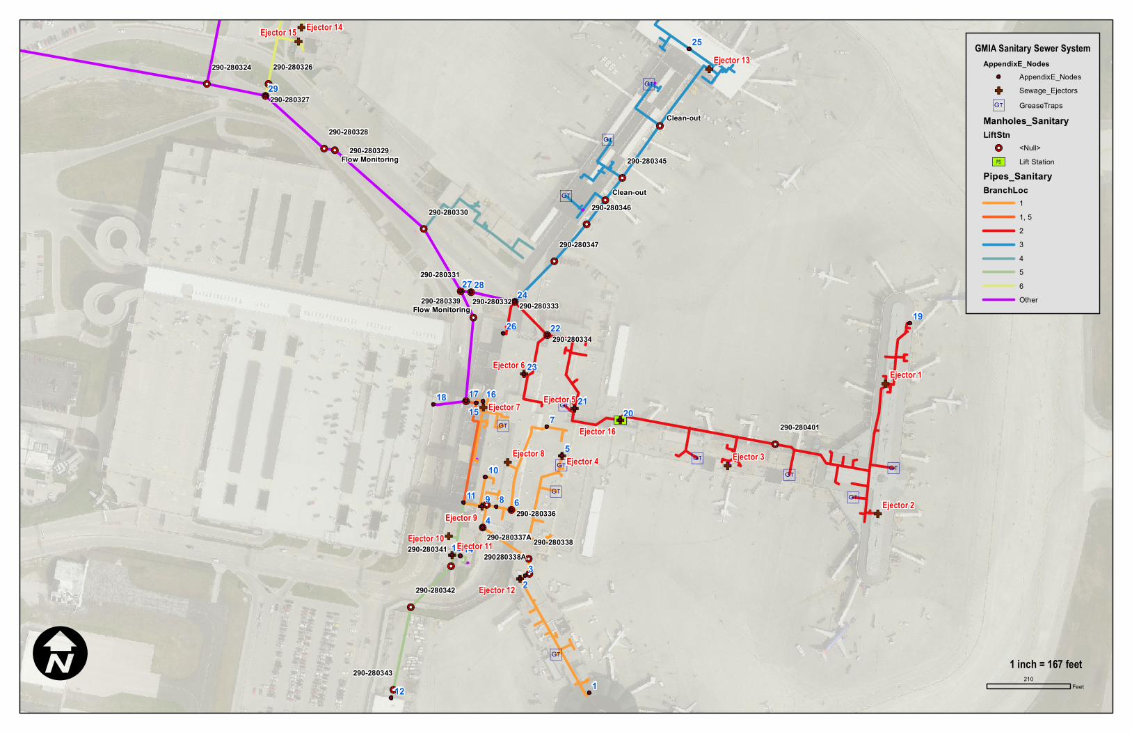
Concourse E This first portion of the system entails the line that serves Concourse E, the south half of the Main Terminal, the south half of Ticketing, the Northwest (Delta) Airlines Maintenance Facility and the proposed Trituration Building. (Nodes 1 to 2) Serves Concourse E and has approximately 280 DFUs on a 6” line which can handle 700 DFUs. The pipe size is adequate for this load. This line is of adequate size from the ejector to the manhole 290-280337A at the south east end of the Baggage Claim (Node 3 to 4). (Nodes 4 to 8) Manhole 290-280337A to manhole 290-280335 with the load being 280 DFUs on a 6” pipe. (Nodes 5 to 6) The next portion of this branch is from the South half of the Terminal and Ticketing which has approximately 176 DFUs. This branch also has one sump (SP-1) collection drainage in the Tug Tunnel (200 DFUs), which puts this line at approximately 376 DFUs. (Nodes 7 to 6) Another portion of this branch is also from the South half of the Terminal and Ticketing which has approximately 50 DFUs. This branch also has one sump (SP-2) collection drainage in the Tug Tunnel (200 DFUS) with the load being approximately 250 DFUs. (Node 6 to 8) From manhole 290-280336 to manhole 290-280335 the load is 626 DFUs on a 6” pipe (Node 8) Manhole (290-280335) collects the discharge from Nodes 4 and 6 for a load of approximately 900 DFUs. (Also, there is an 8” PVC pipe near the top of the manhole that runs to the north; the origin and destination of this line is not known). (Node 8 to 9) The 900 DFUs load for this line feeds into the Pneumatic Sumps with a 6” pipe, which is only supposed to have 700 DFUs. (Node 9) The existing duplex pneumatic pumps are sized at 100 GPM. Per the pump manufacturer, a load of 900 DFUs equals 250 GPM and requires a pump system consisting of two (2) 250 GPM pumps. Out of the Pneumatic Sumps another branch line connects to this with an approximate load of 166 DFUs (Node 10) for a load of 1,066 DFUs on a 6” pipe, which has a capacity of 700 DFUs. This line runs to the west where it connects to the line from the South end of the building (Node 9 to 11).

Terminal Sanitary Utility Study for GMIA Milwaukee County Dept. of Transportation & Public Works
The line from the South end of the building has the loads from the South end of Baggage Claim, NWMF and the proposed Trituration Building. (Nodes 12 to 13) The waste from the NWMF and proposed Trituration Building enter the system into a sewage ejector (SE-2). This load is approximately 30 DFUs on a 6” pipe, which is of adequate capacity. (Node 14) Handles the load from the south end of Baggage Claim with a load 66 DFUs and connects the line from Node 13. (Nodes 14 to 11) This 6” line runs exposed through the Basement level of the Baggage Claim building along the West wall, where it connects with the line from the Pneumatic Sumps. This 6” line has adequate capacity. (Nodes 11 to 15) This line runs north to the point where it exits the building, with a load of approximately 1,166 DFUs; the maximum load for a 6” is 700 DFUs. (Node 16) Is a branch that feeds into this line which serves the basement restrooms and restrooms from the Main Terminal with approximately 160 DFUs on a 5” pipe. This line has adequate capacity. (Node 15 to 17) An approximate load of 1,320 DFUs on a 6” pipe leaves the building and into manhole 290-280340 (Node 17). The maximum load for a 6” is 700 DFUs. (Node 17) manhole 290-280340 collects the load of approximately 80 DFUs from the car rental facilities and leaves the manhole through a 10” pipe carrying 1,400 DFUs. A 10” pipe with a slope 0.27% slope has a capacity of 2,100 DFUs (Per Commerce Table 82,30-3, see graph included in Appendix E).
MH 290-280340
Diameter-Flow-Direction Slope Flow/Load
(DFUs) Pipe Capacity
(DFUs) 6” IN-E* -- 1,320 700 6” IN-W -- 80 700
10” OUT-NW 0.27% 1,400 2,100 * Pipe is being replaced as part of a separate GMIA project.

Terminal Sanitary Utility Study for GMIA Milwaukee County Dept. of Transportation & Public Works
Concourse D (Node 19 to 20) This system in Concourse D has approximately 696 DFUs on a 6” pipe into the sewage ejector/lift station at the northwest end of the concourse (Node 20). (Node 20 to 21) This line pumps into the Terminal on the North end of the Tug Tunnel. (Node 21 to 22) connects with a 200 DFU sump load (SP-3) and connection loads of 170 DFUs for a load of 1,066 DFUs on a 6” pipe that has a design capacity of 700 DFUs. (Node 22) Manhole 290-280334 in the building, it picks up another sump of 200 DFUs (Node 23) for a load of 1,266 DFUs out to manhole 290-280333 (Node 24) north of the building. An 8” pipe with a slope of 3.4% has a capacity of 2,100 DFUs.
MH 290-280334
Diameter-Flow-Direction Slope Flow/Load
(DFUs) Pipe Capacity
(DFUs) 6” IN-E -- 1,066 700
8” IN-SW -- 200 800 8” OUT-NW 3.4% 1,266 2,100

Terminal Sanitary Utility Study for GMIA Milwaukee County Dept. of Transportation & Public Works
Concourse C Concourse C (Node 25) which has approximately 580 DFUs, 50 DFUs is from the trituration sump for a load of 630 DFUs on 10” pipe. This line ties into manhole 290-280333 (Node 24) (Node 24) Manhole 290-280333 also collects a load of 50 DFUs from Node 26 for a combined total of approximately 1,946 DFUs on a 10” pipe. A 10” pipe with a slope of 1.7% has a capacity of 3,200 DFUs.
MH 290-280333 Diameter-Flow-
Direction Slope Flow/Load (DFUs)
Pipe Capacity (DFUs)
6” IN-SW 50 700 8” IN-SE 3.4% 1,266 2,100
10” IN-NE 0.5% 630 2,500 10” OUT-W 1.7% 1,946 3,200
The total load leaving the airport via a 15” pipe is 3,626 DFUs. This estimated flow is below the design capacity of the 15” pipe. Field spot measurements at manholes 290-280339 and 290-280329 verified that the 15” pipe has adequate capacity. A summary of the spot field flow monitoring is provided in Appendix F. This analysis of the GMIA sanitary sewer system identified several internal plumbing deficiencies as the cause of clogging and backups. The exterior sanitary sewer, namely the 15” line, is not the cause of backups based upon total DFU calculation and field verification. It is the recommendation of Kapur & Associates to proceed with the internal recommendations. Should backups continue after these upgrades, periodically check flows in the outside sewers for possible surcharging on peak usage days.

Terminal Sanitary Utility Study for GMIA Milwaukee County Dept. of Transportation & Public Works
TAG/NODE ESTIMATED
LOAD (DFUs)
EXISTING PIPE SIZE
CAPACITY OF PIPE
1 to 2 280 6 700 3 SE 13
3 to 4 280 6 700 5 SP-1 200
5 to 6 375 6 700 6 7 SP-2 200
7 to 6 250 6 700 6 to 8 625 700
8 900 6 700 8 to 9 900 6 700
9
900 DFUs Requires 250 GPM pump,
per manufacturer
Pneumatic Pumps
100 GPM
900 DFUs Requires 250 GPM pump,
per manufacturer
10 to 9 165 6 700 9 to 11 1,065 6 700
12 to 13 30 6 700 13 SE 2 30 6 700 14 65 6 700
14 to 11 100 6 700 11 to 15 1,166 6 700 16 to 15 160 5 390
15 to 17* 1,320 6 700 18 to 17 80 6 700
17 1,400 10 2,100 19 to 20 695 6 700
20 PS 20 to 21 695 6 700
21 SP-3 200 21 to 22 1,066 6 700 23 to 22 SP-4 200 6 700
22 1,266 8 2,100 22 to 24 1,266 8 2,100 26 to 24 50 6 700 25 to 24 630 10 2,500
24 1,946 10 3,200 24 to 27 1,946 10 3,200
* Pipe is being replaced as part of a separate GMIA project.
!!2
!!2
!!2
!!2!!2
!!2
!!2
!!2
!!2
!!2!!2
!!2
!!2!!2
!!2
!!2
!!2
!!2
!!2 !!2
!!2
!!2
!!2
!!2
!!2
[Ú
!!2
!!2
!!2
i
i
i
i
i
iii
i
i
i
i
GF
GF
GF
GFGF
GF
GFGF
GF
GF
GF
GF
GF
GF
GF
GF
9 8
7
6
5
4
32
1
29
2827
26
25
24
23
22
2120
19
18 17 1615
1413
12
11
10
Clean-out
Clean-out
290280338A
290-280401
290-280334
290-280324
290-280327
290-280328
290-280330
290-280331
290-280343
290-280336
290-280338
290-280326
290-280342
290-280341
290-280332 290-280333
290-280347
290-280345
290-280346
290-280337A
290-280329 Flow Monitoring
290-280339 Flow Monitoring
Ejector 3
Ejector 2
Ejector 6
Ejector 8 Ejector 4
Ejector 7 Ejector 5
Ejector 9
Ejector 1
Ejector 16
Ejector 12
Ejector 13
Ejector 10
Ejector 15 Ejector 14
Ejector 11
GMIA Sanitary Sewer SystemAppendixE_Nodes
AppendixE_NodesGF Sewage_Ejectors
i GreaseTrapsManholes_SanitaryLiftStn
!!2 <Null>[Ú Lift Station
Pipes_SanitaryBranchLoc
11, 523456Other
I 210Feet
1 inch = 167 feet

2,000
2,500
3,000
3,500
4,000
4,500
DFU
sDFUs vs. Pipe Slope
From Department of Commerce Table 82.30‐3
10‐inch Pipe
6‐inch Pipe
0
500
1,000
1,500
,
0 1 2 3 4 5
% SLOPE
8‐inch Pipe

Terminal Sanitary Utility Study for GMIA Milwaukee County Dept. of Transportation & Public Works
34
APPENDIX-F: SPOT CHECK FLOW MONITORING

Terminal Sanitary Utility Study for GMIA Milwaukee County Dept. of Transportation & Public Works
GMIA Flow
Measurement, 5/4/12
MH 290‐28033915‐inch OUT (IE = 7.70)
MH 290‐28032915‐inch OUT (IE = 11.85)
Time Top of Flow
Depth (ft)
Slope Flow (cfs)
Top of Flow
Depth (ft)
Slope Flow (cfs)
7:30a 7.60 0.10 0.10 0.28 11.35 0.50 0.0018 0.92
9:30a 7.65 0.05 0.10 0.06 11.35 0.50 0.0018 0.92
11:30a 7.65 0.05 0.10 0.06 11.38 0.47 0.0018 0.82
1:30p 7.60 0.10 0.10 0.28 11.35 0.50 0.0018 0.92
3:30p 7.63 0.07 0.10 0.28 11.43 0.42 0.0018 0.67

Terminal Sanitary Utility Study for GMIA Milwaukee County Dept. of Transportation & Public Works
39
APPENDIX-G: COST ESTIMATES

SUMMARY SHEET
Page System MaterialMaterial
TotalLaborTotal
UG DRAIN CISP -$ 0UG DRAIN PVC SCH. 40 DWV -$ 0UG ACID WASTE POLY PRO -$ 0WASTE & VENT NO HUB -$ 0FUEL GAS BLK. STEEL & MI -$ 0WATER VALVES BRONZE / IRON -$ 0GAS VALVES BRONZE -$ 0RO VALVES PVDF -$ 0DRAINS -$ 0FIXTURES -$ 0
SUBTOTAL -$ MISCELLANEOUS 47,500.00$ 120SUBTOTALS 47,500.00$ 120Escalation (# of years) 1Escalation (% per year) 5% Material SUBTOTAL (Including Escalation) 47,500.00$
Tax 5.5% 2,612.50$ Material TOTAL 50,112.50$
LABOR SUBTOTAL 120.00 hoursLABOR RATE 65.00$ LABOR TOTAL 7,800.00$
MATERIAL & LABOR SUBTOTAL 55,300.00$ Markup (O and P) 15% 8,295.00$ SUBTOTAL 63,595.00$
SUBCONTRACTORSINSULATION -$ SUBTOTAL -$ MARK UP 23.5% -$ SUBCONTRACTOR TOTAL -$
Bond 1.0% 635.95$ TOTAL 64,230.95$ #DIV/0! per sq. ft.Building Square Footage -
Construction Cost % 100% 64,230.95$ #DIV/0! per sq. ft
Total for Plumbing 64,230.95$
Bob
Text Box
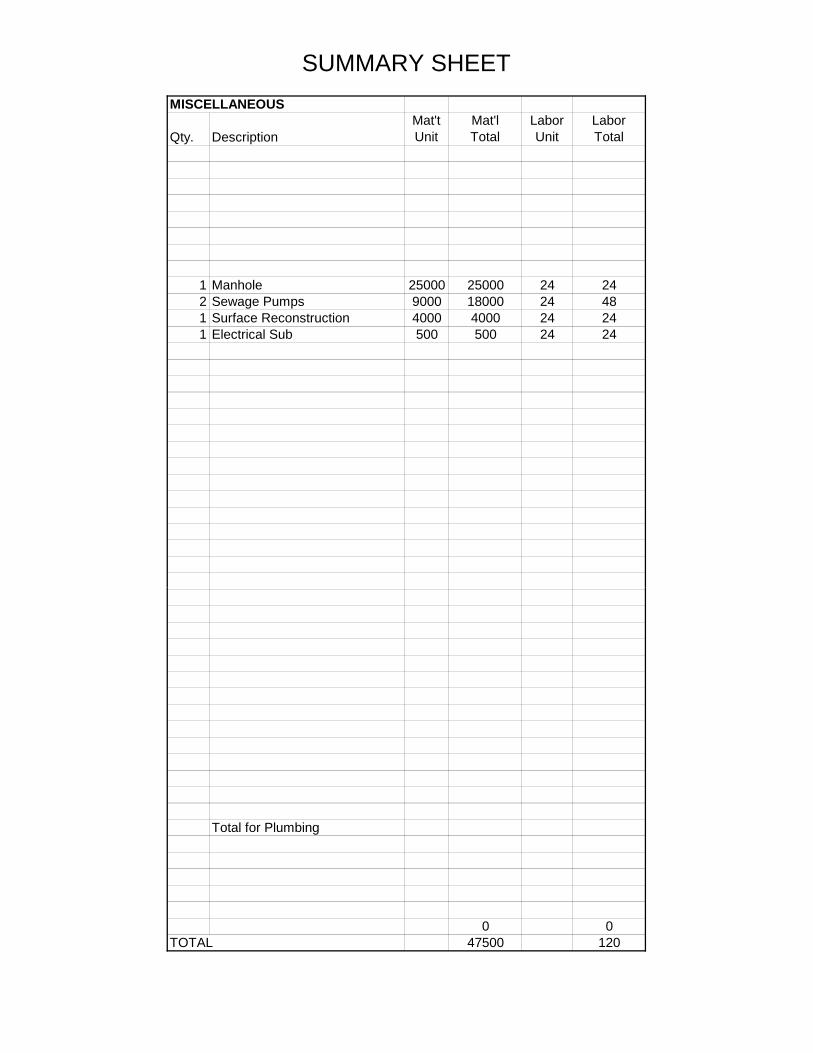
1. Replacement of Sewage Ejector Number 16
SUMMARY SHEET
MISCELLANEOUS
Qty. DescriptionMat'tUnit
Mat'lTotal
LaborUnit
LaborTotal
1 Manhole 25000 25000 24 242 Sewage Pumps 9000 18000 24 481 Surface Reconstruction 4000 4000 24 241 Electrical Sub 500 500 24 24
Total for Plumbing
0 0TOTAL 47500 120

SUMMARY SHEET
Page System MaterialMaterial
TotalLaborTotal
UG DRAIN CISP -$ 0UG DRAIN PVC SCH. 40 DWV -$ 0UG ACID WASTE POLY PRO -$ 0WASTE & VENT NO HUB 1,586.00$ 18.01WASTE & VENT PVC SCH. 40 DWV -$ 0ACID WASTE POLY PRO -$ 0WATER L COPPER -$ 0RO WATER PVDF -$ 0FUEL GAS BLK. STEEL & MI -$ 0WATER VALVES BRONZE / IRON -$ 0GAS VALVES BRONZE -$ 0RO VALVES PVDF -$ 0DRAINS -$ 0FIXTURES -$ 0
SUBTOTAL 1,586.00$ MISCELLANEOUS -$ 5.34SUBTOTALS 1,586.00$ 23.35Escalation (# of years) 2Escalation (% per year) 5% Material SUBTOTAL (Including Escalation) 1,748.57$
Tax 5.5% 96.17$ Material TOTAL 1,844.74$
LABOR SUBTOTAL 23.35 hoursLABOR RATE 65.00$ LABOR TOTAL 1,517.75$
MATERIAL & LABOR SUBTOTAL 3,266.32$ Markup (O and P) 15% 489.95$ SUBTOTAL 3,756.26$
SUBCONTRACTORSINSULATION -$ SUBTOTAL -$ MARK UP 23.5% -$ SUBCONTRACTOR TOTAL -$
Bond 1.0% 37.56$ TOTAL 3,793.82$ #DIV/0! per sq. ft.Building Square Footage -
Construction Cost % 100% 3,793.82$ #DIV/0! per sq. ft
-$
Total for Plumbing 3,793.82$
Bob
Text Box
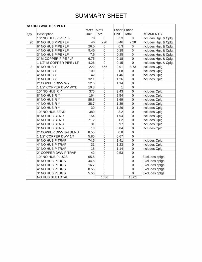
2. Replacement of 6" sanitary line between Manhole 290-280335 and Ejector #9
SUMMARY SHEET
NO HUB WASTE & VENT
Qty. DescriptionMat'tUnit
Mat'lTotal
LaborUnit
LaborTotal COMMENTS
10" NO HUB PIPE / LF 70 0 0.53 0 Includes Hgr. & Cplg.20 8" NO HUB PIPE / LF 46 920 0.46 9.28 Includes Hgr. & Cplg.
6" NO HUB PIPE / LF 26.5 0 0.3 0 Includes Hgr. & Cplg.4" NO HUB PIPE / LF 9.45 0 0.28 0 Includes Hgr. & Cplg.3" NO HUB PIPE / LF 7.6 0 0.25 0 Includes Hgr. & Cplg.2" M COPPER PIPE / LF 6.75 0 0.18 0 Includes Hgr. & Cplg.1 1/2" M COPPER PIPE / LF 4.26 0 0.15 0 Includes Hgr. & Cplg.
3 8" NO HUB Y 222 666 2.91 8.73 Includes Cplg.6" NO HUB Y 109 0 1.8 0 Includes Cplg.4" NO HUB Y 42 0 1.46 0 Includes Cplg.3" NO HUB Y 32.1 0 1.26 0 Includes Cplg.2" COPPER DWV WYE 12.5 0 1.14 0 1 1/2" COPPER DWV WYE 10.8 0 1 0 10" NO HUB R Y 375 0 3.43 0 Includes Cplg.8" NO HUB R Y 164 0 2.54 0 Includes Cplg.6" NO HUB R Y 86.6 0 1.69 0 Includes Cplg.4" NO HUB R Y 38.7 0 1.39 0 Includes Cplg.3" NO HUB R Y 30 0 1.26 0 Includes Cplg.10" NO HUB BEND 380 0 3.2 0 Includes Cplg.8" NO HUB BEND 154 0 1.94 0 Includes Cplg.6" NO HUB BEND 71.2 0 1.2 0 Includes Cplg.4" NO HUB BEND 31 0 0.97 0 Includes Cplg.3" NO HUB BEND 18 0 0.84 0 Includes Cplg.2" COPPER DWV 1/4 BEND 8.55 0 0.8 0 1 1/2" COPPER DWV 1/4 5.85 0 0.67 0 6" NO HUB P TRAP 74.5 0 1.41 0 Includes Cplg.4" NO HUB P TRAP 31 0 1.23 0 Includes Cplg.3" NO HUB P TRAP 18 0 1.14 0 Includes Cplg.2" COPPER DWV P TRAP 42 0 0.53 0 10" NO HUB PLUGS 65.5 0 0 Excludes cplgs.8" NO HUB PLUGS 44.5 0 0 Excludes cplgs.6" NO HUB PLUGS 16.7 0 0 Excludes cplgs.4" NO HUB PLUGS 8.55 0 0 Excludes cplgs.3" NO HUB PLUGS 5.55 0 0 Excludes cplgs.NO HUB SUBTOTAL 1586 18.01

SUMMARY SHEET
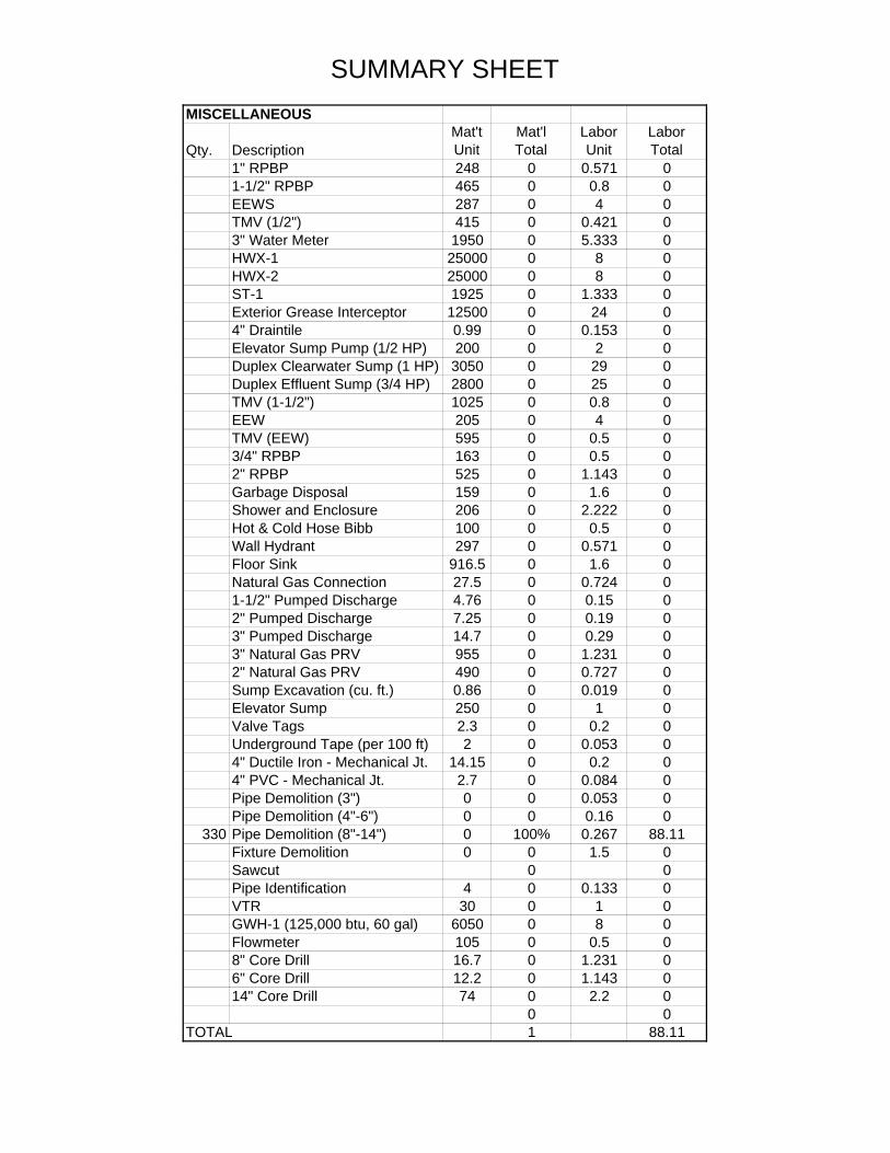
MISCELLANEOUS
Qty. DescriptionMat'tUnit
Mat'lTotal
LaborUnit
LaborTotal
1" RPBP 248 0 0.571 01-1/2" RPBP 465 0 0.8 0EEWS 287 0 4 0TMV (1/2") 415 0 0.421 03" Water Meter 1950 0 5.333 0ET-1 1950 0 1.333 0CP-1 410 0 2.667 0HWX-1 25000 0 8 0HWX-2 25000 0 8 0ST-1 1925 0 1.333 0Exterior Grease Interceptor 12500 0 24 04" Draintile 0.99 0 0.153 0Elevator Sump Pump (1/2 HP) 200 0 2 0Duplex Clearwater Sump (1 HP) 3050 0 29 0Duplex Effluent Sump (3/4 HP) 2800 0 25 0TMV (1-1/2") 1025 0 0.8 0EEW 205 0 4 0TMV (EEW) 595 0 0.5 03/4" RPBP 163 0 0.5 02" RPBP 525 0 1.143 0Hot & Cold Hose Bibb 100 0 0.5 0Wall Hydrant 297 0 0.571 0Floor Sink 916.5 0 1.6 0Natural Gas Connection 27.5 0 0.724 01-1/2" Pumped Discharge 4.76 0 0.15 02" Pumped Discharge 7.25 0 0.19 03" Pumped Discharge 14.7 0 0.29 03" Natural Gas PRV 955 0 1.231 02" Natural Gas PRV 490 0 0.727 0Sump Excavation (cu. ft.) 0.86 0 0.019 0Elevator Sump 250 0 1 0Valve Tags 2.3 0 0.2 0Underground Tape (per 100 ft) 2 0 0.053 04" Ductile Iron - Mechanical Jt. 14.15 0 0.2 04" PVC - Mechanical Jt. 2.7 0 0.084 0Pipe Demolition (3") 0 0 0.053 0Pipe Demolition (4"-6") 0 0 0.16 0
20 Pipe Demolition (8"-14") 0 0 0.267 5.34Fixture Demolition 0 0 1.5 0Sawcut 0 0Pipe Identification 4 0 0.133 0VTR 30 0 1 0GWH-1 (125,000 btu, 60 gal) 6050 0 8 0Flowmeter 105 0 0.5 08" Core Drill 16.7 0 1.231 06" Core Drill 12.2 0 1.143 014" Core Drill 74 0 2.2 0
0 0TOTAL 0 5.34

SUMMARY SHEET
Page System MaterialMaterial
TotalLaborTotal
UG DRAIN CISP -$ 0UG DRAIN PVC SCH. 40 DWV -$ 0UG ACID WASTE POLY PRO -$ 0WASTE & VENT NO HUB -$ 0FUEL GAS BLK. STEEL & MI -$ 0WATER VALVES BRONZE / IRON -$ 0GAS VALVES BRONZE -$ 0RO VALVES PVDF -$ 0DRAINS -$ 0FIXTURES -$ 0
SUBTOTAL -$ MISCELLANEOUS 122,000.00$ 40SUBTOTALS 122,000.00$ 40Escalation (# of years) 1Escalation (% per year) 5% Material SUBTOTAL (Including Escalation) 122,000.00$
Tax 5.5% 6,710.00$ Material TOTAL 128,710.00$
LABOR SUBTOTAL 40.00 hoursLABOR RATE 65.00$ LABOR TOTAL 2,600.00$
MATERIAL & LABOR SUBTOTAL 124,600.00$ Markup (O and P) 15% 18,690.00$ SUBTOTAL 143,290.00$
SUBCONTRACTORSINSULATION -$ SUBTOTAL -$ MARK UP 23.5% -$ SUBCONTRACTOR TOTAL -$
Bond 1.0% 1,432.90$ TOTAL 144,722.90$ #DIV/0! per sq. ft.Building Square Footage -
Construction Cost % 100% 144,722.90$ #DIV/0! per sq. ft
Total for Plumbing 144,722.90$
Bob
Text Box
3. Replacement of Pneumatic Pump with New Pneumatic Pump System

SUMMARY SHEET
MISCELLANEOUS
Qty. DescriptionMat'tUnit
Mat'lTotal
LaborUnit
LaborTotal
1 Set Pnuematic Pumps 120000 120000 24 241 Prep Surface 2000 2000 16 16
Total for Plumbing
0 0TOTAL 122000 40

SUMMARY SHEET
Page System MaterialMaterial
TotalLaborTotal
UG DRAIN CISP -$ 0UG DRAIN PVC SCH. 40 DWV -$ 0UG ACID WASTE POLY PRO -$ 0WASTE & VENT NO HUB 27,640.00$ 212.578WASTE & VENT PVC SCH. 40 DWV -$ 0ACID WASTE POLY PRO -$ 0WATER L COPPER -$ 0RO WATER PVDF -$ 0FUEL GAS BLK. STEEL & MI -$ 0WATER VALVES BRONZE / IRON -$ 0GAS VALVES BRONZE -$ 0RO VALVES PVDF -$ 0DRAINS -$ 0FIXTURES -$ 0
SUBTOTAL 27,640.00$ MISCELLANEOUS 1.00$ 88.11SUBTOTALS 27,641.00$ 300.688Escalation (# of years) 2Escalation (% per year) 5% Material SUBTOTAL (Including Escalation) 30,474.10$
Tax 5.5% 1,676.08$ Material TOTAL 32,150.18$
LABOR SUBTOTAL 300.69 hoursLABOR RATE 65.00$ LABOR TOTAL 19,544.72$
MATERIAL & LABOR SUBTOTAL 50,018.82$ Markup (O and P) 15% 7,502.82$ SUBTOTAL 57,521.64$
SUBCONTRACTORSINSULATION -$ SUBTOTAL -$ MARK UP 23.5% -$ SUBCONTRACTOR TOTAL -$
Bond 1.0% 575.22$ TOTAL 58,096.86$ #DIV/0! per sq. ft.Building Square Footage -
Construction Cost % 100% 58,096.86$ #DIV/0! per sq. ft
Total for Plumbing 58,096.86$
Bob
Text Box
4. Replacement of 6" sanitary drain piping with 10" pipe running from pneumatic pump (Ejector #9) to manhole 290-280340

SUMMARY SHEET
NO HUB WASTE & VENT
Qty. DescriptionMat'tUnit
Mat'lTotal
LaborUnit
LaborTotal COMMENTS
330 10" NO HUB PIPE / LF 70 23100 0.53 173.25 Includes Hgr. & Cplg.8" NO HUB PIPE / LF 46 0 0.46 0 Includes Hgr. & Cplg.6" NO HUB PIPE / LF 26.5 0 0.3 0 Includes Hgr. & Cplg.4" NO HUB PIPE / LF 9.45 0 0.28 0 Includes Hgr. & Cplg.3" NO HUB PIPE / LF 7.6 0 0.25 0 Includes Hgr. & Cplg.2" M COPPER PIPE / LF 6.75 0 0.18 0 Includes Hgr. & Cplg.1 1/2" M COPPER PIPE / LF 4.26 0 0.15 0 Includes Hgr. & Cplg.8" NO HUB Y 222 0 2.91 0 Includes Cplg.6" NO HUB Y 109 0 1.8 0 Includes Cplg.4" NO HUB Y 42 0 1.46 0 Includes Cplg.3" NO HUB Y 32.1 0 1.26 0 Includes Cplg.2" COPPER DWV WYE 12.5 0 1.14 0 1 1/2" COPPER DWV WYE 10.8 0 1 0
4 10" NO HUB R Y 375 1500 3.43 13.728 Includes Cplg.8" NO HUB R Y 164 0 2.54 0 Includes Cplg.6" NO HUB R Y 86.6 0 1.69 0 Includes Cplg.4" NO HUB R Y 38.7 0 1.39 0 Includes Cplg.3" NO HUB R Y 30 0 1.26 0 Includes Cplg.
8 10" NO HUB BEND 380 3040 3.2 25.6 Includes Cplg.8" NO HUB BEND 154 0 1.94 0 Includes Cplg.6" NO HUB BEND 71.2 0 1.2 0 Includes Cplg.4" NO HUB BEND 31 0 0.97 0 Includes Cplg.3" NO HUB BEND 18 0 0.84 0 Includes Cplg.2" COPPER DWV 1/4 BEND 8.55 0 0.8 0 1 1/2" COPPER DWV 1/4 5.85 0 0.67 0 6" NO HUB P TRAP 74.5 0 1.41 0 Includes Cplg.4" NO HUB P TRAP 31 0 1.23 0 Includes Cplg.3" NO HUB P TRAP 18 0 1.14 0 Includes Cplg.2" COPPER DWV P TRAP 42 0 0.53 0 10" NO HUB PLUGS 65.5 0 0 Excludes cplgs.8" NO HUB PLUGS 44.5 0 0 Excludes cplgs.6" NO HUB PLUGS 16.7 0 0 Excludes cplgs.4" NO HUB PLUGS 8.55 0 0 Excludes cplgs.3" NO HUB PLUGS 5.55 0 0 Excludes cplgs.NO HUB SUBTOTAL 27640 212.578
100%
SUMMARY SHEET
MISCELLANEOUS
Qty. DescriptionMat'tUnit
Mat'lTotal
LaborUnit
LaborTotal
1" RPBP 248 0 0.571 01-1/2" RPBP 465 0 0.8 0EEWS 287 0 4 0TMV (1/2") 415 0 0.421 03" Water Meter 1950 0 5.333 0HWX-1 25000 0 8 0HWX-2 25000 0 8 0ST-1 1925 0 1.333 0Exterior Grease Interceptor 12500 0 24 04" Draintile 0.99 0 0.153 0Elevator Sump Pump (1/2 HP) 200 0 2 0Duplex Clearwater Sump (1 HP) 3050 0 29 0Duplex Effluent Sump (3/4 HP) 2800 0 25 0TMV (1-1/2") 1025 0 0.8 0EEW 205 0 4 0TMV (EEW) 595 0 0.5 03/4" RPBP 163 0 0.5 02" RPBP 525 0 1.143 0Garbage Disposal 159 0 1.6 0Shower and Enclosure 206 0 2.222 0Hot & Cold Hose Bibb 100 0 0.5 0Wall Hydrant 297 0 0.571 0Floor Sink 916.5 0 1.6 0Natural Gas Connection 27.5 0 0.724 01-1/2" Pumped Discharge 4.76 0 0.15 02" Pumped Discharge 7.25 0 0.19 03" Pumped Discharge 14.7 0 0.29 03" Natural Gas PRV 955 0 1.231 02" Natural Gas PRV 490 0 0.727 0Sump Excavation (cu. ft.) 0.86 0 0.019 0Elevator Sump 250 0 1 0Valve Tags 2.3 0 0.2 0Underground Tape (per 100 ft) 2 0 0.053 04" Ductile Iron - Mechanical Jt. 14.15 0 0.2 04" PVC - Mechanical Jt. 2.7 0 0.084 0Pipe Demolition (3") 0 0 0.053 0Pipe Demolition (4"-6") 0 0 0.16 0
330 Pipe Demolition (8"-14") 0 100% 0.267 88.11Fixture Demolition 0 0 1.5 0Sawcut 0 0Pipe Identification 4 0 0.133 0VTR 30 0 1 0GWH-1 (125,000 btu, 60 gal) 6050 0 8 0Flowmeter 105 0 0.5 08" Core Drill 16.7 0 1.231 06" Core Drill 12.2 0 1.143 014" Core Drill 74 0 2.2 0
0 0TOTAL 1 88.11

SUMMARY SHEET
Page System MaterialMaterial
TotalLaborTotal
UG DRAIN CISP -$ 0UG DRAIN PVC SCH. 40 DWV -$ 0UG ACID WASTE POLY PRO -$ 0WASTE & VENT NO HUB 14,051.40$ 149.06WASTE & VENT PVC SCH. 40 DWV -$ 0ACID WASTE POLY PRO -$ 0WATER L COPPER -$ 0RO WATER PVDF -$ 0FUEL GAS BLK. STEEL & MI -$ 0WATER VALVES BRONZE / IRON -$ 0GAS VALVES BRONZE -$ 0RO VALVES PVDF -$ 0DRAINS -$ 0FIXTURES -$ 0
SUBTOTAL 14,051.40$ MISCELLANEOUS -$ 102.915SUBTOTALS 14,051.40$ 251.975Escalation (# of years) 2Escalation (% per year) 5% Material SUBTOTAL (Including Escalation) 15,491.67$
Tax 5.5% 852.04$ Material TOTAL 16,343.71$
LABOR SUBTOTAL 251.98 hoursLABOR RATE 65.00$ LABOR TOTAL 16,378.38$
MATERIAL & LABOR SUBTOTAL 31,870.04$ Markup (O and P) 15% 4,780.51$ SUBTOTAL 36,650.55$
SUBCONTRACTORSINSULATION -$ SUBTOTAL -$ MARK UP 23.5% -$ SUBCONTRACTOR TOTAL -$
Bond 1.0% 366.51$ TOTAL 37,017.06$ #DIV/0! per sq. ft.Building Square Footage -
Construction Cost % 100% 37,017.06$ #DIV/0! per sq. ft
-$
Total for Plumbing 37,017.06$
Bob
Text Box
5. Replacement of 6" sanitary line with 8" pipe between ejector #16 and manhole 290-28344

SUMMARY SHEET
NO HUB WASTE & VENT
Qty. DescriptionMat'tUnit
Mat'lTotal
LaborUnit
LaborTotal COMMENTS
10" NO HUB PIPE / LF 70 0 0.53 0 Includes Hgr. & Cplg.245 8" NO HUB PIPE / LF 46 11270 0.46 113.68 Includes Hgr. & Cplg.
6" NO HUB PIPE / LF 26.5 0 0.3 0 Includes Hgr. & Cplg.4" NO HUB PIPE / LF 9.45 0 0.28 0 Includes Hgr. & Cplg.3" NO HUB PIPE / LF 7.6 0 0.25 0 Includes Hgr. & Cplg.2" M COPPER PIPE / LF 6.75 0 0.18 0 Includes Hgr. & Cplg.1 1/2" M COPPER PIPE / LF 4.26 0 0.15 0 Includes Hgr. & Cplg.
6 8" NO HUB Y 222 1332 2.91 17.46 Includes Cplg.6" NO HUB Y 109 0 1.8 0 Includes Cplg.4" NO HUB Y 42 0 1.46 0 Includes Cplg.3" NO HUB Y 32.1 0 1.26 0 Includes Cplg.2" COPPER DWV WYE 12.5 0 1.14 0 1 1/2" COPPER DWV WYE 10.8 0 1 0 10" NO HUB R Y 375 0 3.43 0 Includes Cplg.
4 8" NO HUB R Y 164 655.4 2.54 10.16 Includes Cplg.6" NO HUB R Y 86.6 0 1.69 0 Includes Cplg.4" NO HUB R Y 38.7 0 1.39 0 Includes Cplg.3" NO HUB R Y 30 0 1.26 0 Includes Cplg.10" NO HUB BEND 380 0 3.2 0 Includes Cplg.
4 8" NO HUB BEND 154 616 1.94 7.76 Includes Cplg.6" NO HUB BEND 71.2 0 1.2 0 Includes Cplg.4" NO HUB BEND 31 0 0.97 0 Includes Cplg.3" NO HUB BEND 18 0 0.84 0 Includes Cplg.2" COPPER DWV 1/4 BEND 8.55 0 0.8 0 1 1/2" COPPER DWV 1/4 5.85 0 0.67 0 6" NO HUB P TRAP 74.5 0 1.41 0 Includes Cplg.4" NO HUB P TRAP 31 0 1.23 0 Includes Cplg.3" NO HUB P TRAP 18 0 1.14 0 Includes Cplg.2" COPPER DWV P TRAP 42 0 0.53 0 10" NO HUB PLUGS 65.5 0 0 Excludes cplgs.
4 8" NO HUB PLUGS 44.5 178 0 Excludes cplgs.6" NO HUB PLUGS 16.7 0 0 Excludes cplgs.4" NO HUB PLUGS 8.55 0 0 Excludes cplgs.3" NO HUB PLUGS 5.55 0 0 Excludes cplgs.NO HUB SUBTOTAL 14051.4 149.06

SUMMARY SHEET
MISCELLANEOUS
Qty. DescriptionMat'tUnit
Mat'lTotal
LaborUnit
LaborTotal
1" RPBP 248 0 0.571 01-1/2" RPBP 465 0 0.8 0EEWS 287 0 4 0TMV (1/2") 415 0 0.421 03" Water Meter 1950 0 5.333 0ET-1 1950 0 1.333 0CP-1 410 0 2.667 0HWX-1 25000 0 8 0HWX-2 25000 0 8 0ST-1 1925 0 1.333 0Exterior Grease Interceptor 12500 0 24 04" Draintile 0.99 0 0.153 0Elevator Sump Pump (1/2 HP) 200 0 2 0Duplex Clearwater Sump (1 HP) 3050 0 29 0Duplex Effluent Sump (3/4 HP) 2800 0 25 0TMV (1-1/2") 1025 0 0.8 0EEW 205 0 4 0TMV (EEW) 595 0 0.5 03/4" RPBP 163 0 0.5 02" RPBP 525 0 1.143 0Hot & Cold Hose Bibb 100 0 0.5 0Wall Hydrant 297 0 0.571 0Floor Sink 916.5 0 1.6 0Natural Gas Connection 27.5 0 0.724 01-1/2" Pumped Discharge 4.76 0 0.15 02" Pumped Discharge 7.25 0 0.19 03" Pumped Discharge 14.7 0 0.29 03" Natural Gas PRV 955 0 1.231 02" Natural Gas PRV 490 0 0.727 0Sump Excavation (cu. ft.) 0.86 0 0.019 0Elevator Sump 250 0 1 0Valve Tags 2.3 0 0.2 0Underground Tape (per 100 ft) 2 0 0.053 04" Ductile Iron - Mechanical Jt. 14.15 0 0.2 04" PVC - Mechanical Jt. 2.7 0 0.084 0Pipe Demolition (3") 0 0 0.053 0Pipe Demolition (4"-6") 0 0 0.16 0
245 Pipe Demolition (8"-14") 0 0 0.267 65.415Fixture Demolition 0 0 1.5 0
125 Sawcut 0 0.3 37.5Pipe Identification 4 0 0.133 0VTR 30 0 1 0GWH-1 (125,000 btu, 60 gal) 6050 0 8 0Flowmeter 105 0 0.5 08" Core Drill 16.7 0 1.231 06" Core Drill 12.2 0 1.143 014" Core Drill 74 0 2.2 0
0 0TOTAL 0 102.915

Terminal Sanitary Utility Study for GMIA Milwaukee County Dept. of Transportation & Public Works
17
Grease Interceptors Facility Location Suggested Grease Trap Location Cost Cooler By The Lake E Concourse Apron Level Mechanical Room $9,500
Northpoint Main Terminal TBD $15,000
Famigilia’s Pizza & Brew Haus
Main Terminal
In Baggage Makeup as piping drops through the space $15,000
Noona’s D Concourse Apron Level Mechanical Room $9,500 Johnny Rockets & Usinger’s D Concourse TBD $9,500 Chili’s C Concourse Apron Level Mechanical Room $9,500 Pizza Hut C Concourse Apron Level Mechanical Room $9,500 Estimated Total Cost $77,500