TERA Joint - VO&VO | napredne tehnologije · TERA Joint stainless S235JR EZP 1.4301/1.4401 S355J2+N...
16
TERA Joint High quality floor joint system 6/2008
Transcript of TERA Joint - VO&VO | napredne tehnologije · TERA Joint stainless S235JR EZP 1.4301/1.4401 S355J2+N...

TERA JointHigh quality fl oor joint system
6/2008

Peikko® TERA Joint
Peikko benefi ts
reliable: passed demanding test • program
competitive price and delivery • time
economical and easy to use in • designing, manufacturing and installation of the elements
Benefi ts of Peikko® TERA Joint
Advanced ‘leave-in-place’ concrete slab formwork system with integral • load transfer capability and edge protection
Excellent straightness tolerances•
High precision cold-drawn steel edge protection rails with ‘sharp’ edges are • used to eliminate any weakness or friability in the edge of the concrete slab
Fast installation with accessories and completely without welding•
Helps to ensure a trouble-free fl oor for the life-cycle of the building•
Joint uses a signifi cant percentage of sustainable material in its • construction

3www.peikko.com
CONTENTS
1. DESCRIPTION OF THE SYSTEM .......................4
2. DIMENSIONS AND MATERIALS ......................4
3. MANUFACTURING ..........................................63.1 Manufacturing method 6
3.2 Manufacturing tolerances 6
3.3 Quality control 6
4. CAPACITIES ....................................................64.1 Capacities of the TERA Dowel 6
5. APPLICATION ..................................................75.1 Limitations for application 7
5.2 Design principles 7
5.3 Joint and dowel types 8
5.4 Load-transfer 8
5.5 Joint spacing and detailing 8
5.6 Isolation details 8
5.7 Single dowels and sleeves 8
5.8 Accessories 9
5.9 Example 9
6. INSTALLATION ................................................96.1 Installation tolerances 9
6.2 Installation of the fl oor joints 10
6.3 Installation of the single dowels and sleeves 15
7. INSTALLATION CONTROL ..............................157.1 Installation control of the fl oor joint 15
7.2 Installation control of the single dowels and sleeves 15

4
TERA Joint
1. DESCRIPTION OF THE SYSTEMPeikko® TERA Joint fl oor joint system offers the best practical and technical solution for today’s high quality concrete ground fl oor slabs. The sys-tem ensures adequate load transfer in expansion, contraction and construction joints and eliminates resistance to joint opening and movement in two directions in horizontal plane. The system also provides extremely durable edge protection to the concrete slabs, particularly when subjected to traffi c
The load transfer is achieved by high strength steel circular plate dowels which are combined with rigid release sleeves to allow free slab movements in both longitudinal and perpendicular directions, eliminating the principle cause of shrinkage cracks.
The TERA Joint system also acts as self-contained leave-in-place formwork requiring no stripping after pouring saving signifi cant time and manpower. Using this system means faster and easier fl oor slab construction, better quality fl oors and maintenance-free joints. They can be used in ground-supported slabs starting from 100 mm slab thickness.
The system consists of the armoured joints them-selves along with easy to use junction pieces and installation parts.
The circular plate dowels and sleeves are also avail-able separately for use with traditional timber form-work as a solution to the problem of slab locking caused by conventional dowels.
Circular dowels pictured are not available in the UK. Please contact your Peikko representative for de-tails of UK specifi cations.
Figure 1. Peikko TERA Joint system in ground fl oor slab and section of TERA Joint
2. DIMENSIONS AND MATERIALSTable 1. Materials and standards.
Sheet metal Flat bars Plate dowels Headed studs Plastic sleeves
TERA Joint S235JR S235JRC+C S355J2+N S235J2+C450 ABS
TERA Joint HDG S235JR EZP S235JRC+C HDG S355J2+N HDG S235J2+C450 HDG ABS
TERA Joint stainless S235JR EZP 1.4301/1.4401 S355J2+N HDG 1.4301/1.4303 ABS
EZP = electro zinc plated, HDG = hot dip galvanized. Standard for black steel is EN 10025 and EN 10088 for stainless.
A - A

5www.peikko.com
Table 2. Dimensions [mm] of TERA Joint
c/c
80 L
h
type height h dowel sizedowel
centres c/clength L weight [kg]
advisable slab depth
TJ6-90-3000 90
6 x d150 375 3000
31,2 100-120
TJ6-115-3000 115 32,4 125-140
TJ6-135-3000 135 33,9 145-165
TJ6-160-3000 160 35,1 170-190
TJ6-185-3000 185 36,3 195-220
TJ6-215-3000 215 37,8 225-250
TJ6-230-3000 230 38,5 240-270
TJ6-245-3000 245 39,2 255-295
TJ12-140-3000 140
(6+6) x d150
375 3000
40,7 150-170
TJ12-165-3000 165 41,9 175-195
TJ12-190-3000 190 43,1 200-225
TJ12-220-3000 220 44,6 230-250
TJ12-235-3000 235 45,3 250-270
TJ12-250-3000 250 46,0 265-300
Table 3. Dimensions [mm] of TERA X-Junction
h
L1
80
80
L2
type height h width L1 width L2 weight [kg] compatible with
TJX-90 90
400 400
6,3 TJ6-90
TJX-115 115 6,7 TJ6-115
TJX-135 135 7,0 TJ6-135/TJ12-140
TJX-160 160 7,4 TJ6-160/TJ12-165
TJX-185 185 7,8 TJ6-185/TJ12-190
TJX-215 215 8,2 TJ6-215/TJ12-220
TJX-230 230 8,5 TJ6-230/TJ12-235
TJX-245 245 8,7 TJ6-245/TJ12-250
Table 4. Dimensions [mm] of TERA T-Junction
h
80
L2L1
80
type height h width L1 width L2 weight compatible with
TJT-90 90
160 400
4,9 TJ6-90
TJT-115 115 5,3 TJ6-115
TJT-135 135 5,6 TJ6-135/TJ12-140
TJT-160 160 5,9 TJ6-160/TJ12-165
TJT-185 185 6,3 TJ6-185/TJ12-190
TJT-215 215 6,7 TJ6-215/TJ12-220
TJT-230 230 6,9 TJ6-230/TJ12-235
TJT-245 245 7,1 TJ6-245/TJ12-250

6
TERA Joint
3. MANUFACTURING3.1 Manufacturing methodFlat bars Mechanical cutting and punching Plates Mechanical cutting and precision foldingWelding Spot welding and drawn arc stud welding Sleeves Injection moulding
Welding class C (ISO-EN 5817)
3.2 Manufacturing tolerances
Straightness ±2.0 mm/mLength ±2.0 mmHeight ±3.0 mm
3.3 Quality control
The quality control involved in producing the steel parts conforms to the requirements set by the Finn-ish Code of Building Regulations. Peikko Finland Oy is under the Inspecta Certifi cation for quality control.
4. CAPACITIESTERA dowels are designed according to the Techni-cal Report No. 34 of British Concrete Society. The ultimate load transfer capacities are calculated for shear, bearing and bending. Combined shear and bending has to be checked case by case with fol-lowing equation.
4.1+bend
app
sh
app
PP
PP
•
Papp = applied load per dowel Psh = ultimate shear capacity per dowel Pbend = ultimate bending capacity per dowel
The ultimate punching shear capacities are based on full scale tests and include partial safety factors 1,6 for loads and 1,5 for concrete. These provide global safety factor 2,4 against concrete failure. All values are for plain concrete without additional shear reinforcement. In punching shear capacity values it is assumed that the dowel is located at the level of half slab thickness. Punching shear cal-culation method for reinforced concrete by TR34 is not suitable for defi ning punching capacity for TERA dowel. The same capacities are valid for armoured rails and single dowels with sleeves.
Allowed load transfer capacities are obtained by dividing the ultimate capacity values by 1.6.
4.1 Capacities of the TERA DowelThe following tables show the ultimate capacities for a single plate dowel. If capacities for other joint openings or concrete grades are needed please contact your local Peikko Technical Support.
Table 6. Design capacities in shear, bearing and bending [kN] of the TERA Dowels according to TR34
Dowel type
join
t openin
g x
Shear
Psh
Bear
ing P
bear
(C32/4
0)
Bendin
g P
bend
Com
bin
ed P
sh
and P
bend
TJD-C6 10 144,0 78,3 80,0 72,0
TJD-C12 10 288,0 78,3 160,0 144,0
TJD-C6 20 137,0 59,4 38,1 41,7
TJD-C12 20 274,0 59,4 76,2 83,4
Table 5. Dimensions [mm] of TERA Dowel and Sleeve
TJD
TJS dowel type thickness t diameter d sleeve typeadvisable joint
opening
TJD-C6 6 150 TJS-C6 0-15
TJD-C12 6+6 150 TJS-C12 15-20
7www.peikko.com
Table 7. Comparison of the most common dowels with 10 mm joint opening
Table 8. Comparison of the most common dowels with 20 mm joint opening
Measuring design capacity [kN] of single dowels in shear, bearing C32/40, bending and combined shear and bending acc. to TR34. Punching capacity is not included in the comparison charts.
Table 9. Design punching shear capacities [kN] of the TERA Dowels according to full scale tests
Slab depth [mm] P
unch
ing
Pp C
25/3
0
Punch
ing
Pp C
28/3
5
Punch
ing
Pp C
30/3
7
Punch
ing
Pp C
32/4
0
Punch
ing
Pp C
35/4
5
100 4,0 4,3 4,4 4,6 4,8
150 7,7 8,1 8,4 8,7 9,1
200 12,5 13,2 13,6 14,1 14,7
250 18,3 19,4 20,1 20,7 21,7
Intermediate values of the punching shear can be interpolated.
5. APPLICATION5.1 Limitations for applicationThe load transfer capacities of the fl oor joints have been calculated for static loads. In the case of dy-namic and fatigue loads, greater safety factors have to be used individually for each case.
TERA Joints are designed to open up to 20mm. If wider joint openings are designed the capacities have to be reduced appropriately.
The standard joints are without any surface treatment. If protective painted, hot dip galvanized, stainless or acid proof joints are needed due to exposure condi-tions please contact your local Peikko Sales Offi ce.
5.2 Design principles
The capacity values of the dowels do not take ac-count of the sub-base support pressure which is the worst-case scenario.
The effective number of dowels can be defi ned accord-ing to sections 9.10.1 and 9.4.6 of the UK Concrete Society TR34 Third Edition published March 2003.
TR34 recommends that the load transfer should be determined from the capacity of the dowels within a distance of 0,9l either side of the centre-line of the applied load.
For defi ning the number of effective dowels the modulus of subgrade reaction [k] and radius of rela-tive stiffness [l] are required.
Figure 2. The effective number of dowels
18,4
31,6
42,7
50,0
53,5
72,0
78,3
10,0 20,0 30,0 40,0 50,0 60,0 70,0 80,0
16mm round bar
20mm round bar
20mm square bar
6mm triangular plate
25mm round bar
TERA Dowel TJD-C6
TERA Dowel TJD-C12
12,8
22,7
23,9
31,6
38,1
40,0
59,4
16mm round bar
20mm round bar
20mm square bar
6mm triangular plate
25mm round bar
TERA Dowel TJD-C6
TERA Dowel TJD-C12
10,0 20,0 30,0 40,0 50,0 60,0
0,9 l 0,9 l
P

8
TERA Joint
5.3 Joint and dowel typesThe correct joint type is selected according to slab depth. It is recommended to order joints at least 10 mm shallower than the slab depth to ensure easy installation.
TERA dowels are selected according to designed joint opening. Joints TJ6 and dowels TJD6 are for openings up to 15 mm. Types TJ12 and TJD12 are for openings from 15 to 20 mm. It is recommended to use the stronger dowels always in suspended slabs.
5.4 Load-transfer
The punching shear capacity of the concrete is the limiting factor in most cases. All punching ca-pacities given in this brochure are for un-reinforced concrete. If additional reinforcement or fi bre rein-forced concrete is used, the punching capacity can be increased and should be considered by the slab designer in each case.
In TR34, section 9.10.1 it is recommended that no more than half of the applied load should be trans-ferred via dowels. The slab itself should be designed to carry the rest of the load. In practice the capacity of a slab at joints is about 50% (25% at corners) of the capacity at the centre of the slab.
Figure 3. Load transfer
5.5 Joint spacing and detailingThe joint spacing and aspect ratio of slab areas should be designed according to usual recommen-dations. For example individual slabs should ideally have an aspect ratio of 1:1 (square) but if this is not possible then the ratio should never exceed 1:1.5 Slabs should also ideally be no more than 50 m in length/width.
TERA Joint is recommended for all types of free-movement joints and also as a substitute for sawn joints. If used in place of saw cuts, the joint open-ings will be small and the load-transfer capacity higher and similar everywhere. Also the importance of timing of sawing can be ignored. The joints are designed to open up to 20mm during shrinkage of adjacent slabs.
5.6 Isolation details
Fixed elements such as columns and walls should be isolated to avoid any restraint on the slab. The fi xed elements should be separated from the slab by a fl exible compressible fi ller material of at least 20 mm in thickness.
Figure 4. Example of isolation
5.7 Single dowels and sleevesSingle TJD dowels and TJS sleeves can be used with formwork as a substitute for traditional dowel sys-tems. They allow better slab movements in both lon-gitudinal and perpendicular directions. The sleeves are delivered with nails and protective tape.
Figure 5. TERA dowels and sleeves
P

9www.peikko.com
5.8 AccessoriesTERA junction pieces are selected according to joint type. Prefabricated junction pieces allow easy and fast installation in diffi cult joint intersections.
Thus the dowels cannot carry the full load 80 kN, the edge of the slab itself should be checked for its capacity to carry the remaining load 46,4 kN.
6. INSTALLATION6.1 Installation tolerancesJoints should be installed as precisely vertical as practical and checked with a spirit level to ensure proper function of the dowels during slab move-ment. The levelness and straightness of the joint in-stallation should be according to the requirements of the fl oor slab design and again checked using a standard laser level device.
Modular X- and T-pieces are connected to rails with standard bolt and nut connections.
5.9 Example
This example demonstrates how the load transfer capacity of the TERA dowels can be checked. It is assumed that there is one point load at the joint. The loadings and design data for the example are as follows:
Slab depth, h=175 mm, concrete C32/40• Joint opening, x=10 mm• Dowel centres, c/c=375 mm• Maximum wheel load, P=50 kN, safety factor • for dynamic actions 1,6Value of modulus of subgrade reaction for well • compacted sand, k=0,05 N/mm2
Radius of relative stiffness, l=744 mm• Minimum ultimate capacity per dowel, • Pp=11,2 kN
Effective number of dowels according to TR34:
9,02 ln 7449,02 mm 3375/ mmcc
•
Ultimate design load:
kNkNPPd 80506,1•
Required load transfer capacity:
kNkNkNPnP pd 4,462,11380•
Figure 6. TERA T-junction

10
TERA Joint
6.2 Installation of the fl oor joints
To install TERA Joints:
Step 1. Sub-base levelThe sub-base must be made as accurate and level as possible to the requirements on the slab draw-ing. The tolerance of the level has to be taken into account when ordering joints. Typically the Joint height will be 10 mm to 25 mm less than the slab depth.
Step 2. Joint locationThe required layout, position and height of the joints will be specifi ed on the fl oor slab drawing which must be followed closely. String lines are placed to identify the position of joints according to the slab layout drawings. String lines usually run between columns or from junction pieces to column/wall.
Step 3. Joint installation
1. Joints are placed sequentially away from junction pieces or from column/wall
a. If Junction pieces are used the fi rst joint is connected to the junction piece at the overlap section using a dowel bush, plastic bolt and steel nut.
b. If junction pieces are not used the fi rst joint is placed adjacent to column or wall (allowing for isolation material (min. 20 mm closed cell foam).

11www.peikko.com
2. The joints are placed in the correct position ac-cording to the string line and the height adjusted using spacers, wedges or equivalent means until correct. The height should be verifi ed by laser level at both ends and the joint should be set vertical using a spirit level which can be placed across the top edges.
3. The joint can then be fi xed in position using pins.Fixing pins should be 14 mm – 16 mm diam-eter and at least 300 mm longer than the joint height.
For slabs up to 200 mm deep 4 pins per joint are • required, (up to 300 mm 6 pins per joint). The pins should be spaced equally along one side of the joint, (ideally the side without sleeves) and if possible on the opposite side to the fi rst pour if applicable.
Alternate pins should be placed vertically and • fi xed approximately half-way along the length of the studs and at an angle of approximately 30 degrees to the vertical away from the joint and fi xed at the end of the studs. This ensures ex-cellent stability and if it is possible to do the fi rst pour on the opposite side to the pins then it will allow them to be sawn through before pouring the second side reducing any resistance to joint opening.
Pins should always be placed so that they fi nish • level with the stud and if necessary any excess pin above the level of the stud should be re-moved prior to pouring.

12
TERA Joint
a. Pins can be simply driven into place with a suit-able impact gun and chuck.
b. Alternatively holes can be drilled to suit the pin and permit easy installation with a hammer. The holes should be drilled with a bit approxi-mately 2 mm smaller than the pin diameter and to a depth of at most 100 mm less than the fi nal depth of the pin. For example a 250 mm slab using 235 mm joints and 600 mm pins should use a hole drilled to approximately 250 mm – 270 mm deep.
Pins are then welded to the adjacent stud se-• curing the joint into position.
4. Subsequent joints are aligned, fi xed at the over-lap using dowel bushes, plastic bolts and nuts, adjusted and fi xed in the same manner. The joints should be fi xed so that the ends of adjacent top strips are not touching but have a clearance gap of between 1 mm and 2 mm to allow for longitu-dinal movement.
13www.peikko.com
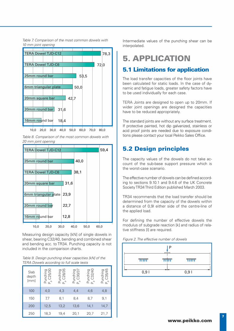
5. The fi nal joint in any run will usually require being cut to length.
The gap between the column/wall and the • penultimate joint is measured taking account of suitable isolation material.The fi nal joint is cut to length and installed in • the same manner as previous joints.
6. If the joint layout requires a run of joints between two junction pieces and the distance between them is not a full multiple of 3 metres then there will need to be a cut joint in the run.
Joints should be placed running from the • junction pieces to some point approximately equidistant from both when the gap is less than 3 m.
The gap should be measured accurately • between the top strips on either side of the joint and the measured value subtracted from 3000 mm to give Lr (the length of joint to be removed in mm).The fi nal joint should have a section cut from • the centre equal to Lr keeping both overlap sections at the ends intact.The two pieces are then installed in the • usual manner to each side of the gap and the square ends of pieces A and B simply butt-welded together at the joint.It is advised to clamp the square ends carefully during weld-ing to ensure a perfectly straight connection between the two pieces. Centre section should be retained for further use for exam-ple in doorways.
7. If required by the design ‘X’ or ‘T’ junctions should be placed according to the required layout and set to the correct height using a laser level or equivalent.
The junction pieces are placed in the cor-• rect position and the height adjusted using spacers, wedges or equivalent means until correctThe height should be verifi ed by laser level • and the junction should be set horizontal using a spirit level in two perpendicular directionsThe junction pieces can then be fi xed in posi-• tion using pins as described in section 3 (p. 11). ‘X’ junctions require 4 pins and ‘T’ junc-tions 3 pins.
8. As an alternative and if pins are not available then the joints and junction pieces can be positioned and held in place by concrete ‘dabs’
The joints and intersections must be posi-• tioned accurately and supported.The dabs should be placed at 1 m spacing • along the joint lengths or at the centre of the intersection pieces. Dabs should be suffi cient to support the rails • during pouring and levelling of the concrete ideally conical in shape and poured up to at least half the depth of the rail.Dabs should be allowed to harden suffi ciently • before removing support.
L
B A3000 - L = Lr
A + B = L

14
TERA Joint
Step 4. Pouring concreteOnce rails are correctly positioned pouring of con-crete can commence. Concrete should be poured to the level of the rails with particular attention to consolidation around the dowels and sleeves. All plate type dowels require close attention to fi lling around the dowels to eliminate the possibility of air entrapment. This should be done with a suitable vibratory poker. Both sides of joints can be poured at the same time if required.
Clarifying installation animation is available from www.peikko.com or from your local Peikko Sales Offi ce.
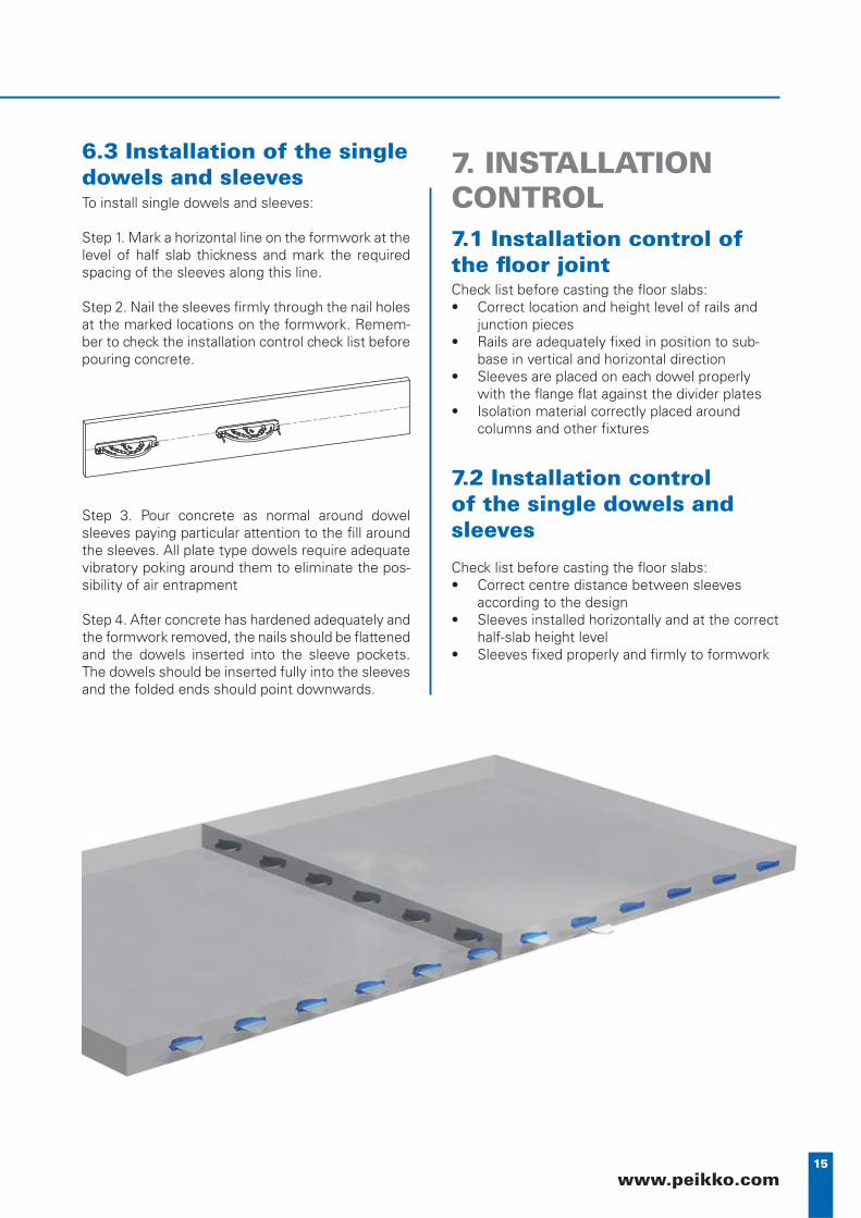
15www.peikko.com
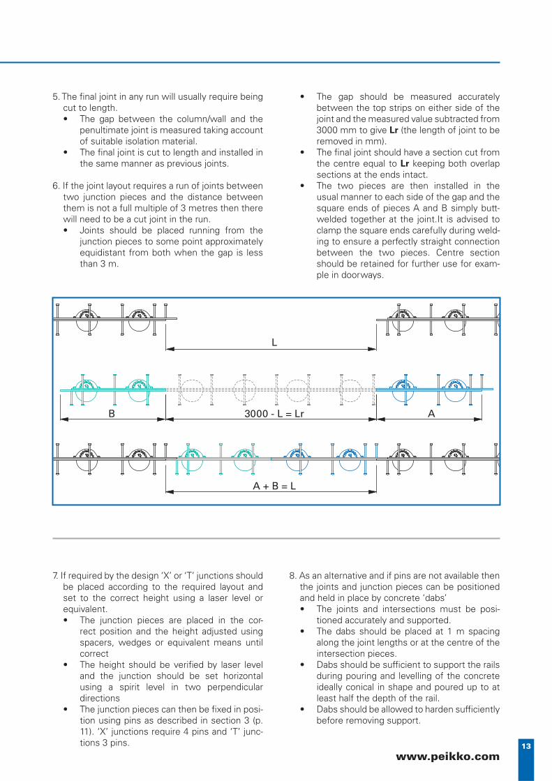
6.3 Installation of the single dowels and sleevesTo install single dowels and sleeves:
Step 1. Mark a horizontal line on the formwork at the level of half slab thickness and mark the required spacing of the sleeves along this line.
Step 2. Nail the sleeves fi rmly through the nail holes at the marked locations on the formwork. Remem-ber to check the installation control check list before pouring concrete.
Step 3. Pour concrete as normal around dowel sleeves paying particular attention to the fi ll around the sleeves. All plate type dowels require adequate vibratory poking around them to eliminate the pos-sibility of air entrapment
Step 4. After concrete has hardened adequately and the formwork removed, the nails should be fl attened and the dowels inserted into the sleeve pockets. The dowels should be inserted fully into the sleeves and the folded ends should point downwards.
7. INSTALLATION CONTROL7.1 Installation control of the fl oor jointCheck list before casting the fl oor slabs:
Correct location and height level of rails and • junction piecesRails are adequately fi xed in position to sub-• base in vertical and horizontal directionSleeves are placed on each dowel properly • with the fl ange fl at against the divider platesIsolation material correctly placed around • columns and other fi xtures
7.2 Installation control of the single dowels and sleeves
Check list before casting the fl oor slabs:Correct centre distance between sleeves • according to the designSleeves installed horizontally and at the correct • half-slab height levelSleeves fi xed properly and fi rmly to formwork•

Peikko Group • www.peikko.com