Tension Analysis of Submarine Cables During Laying...
10
Send Orders of Reprints at [email protected] 282 The Open Civil Engineering Journal, 2013, 7, 282-291 1874-1495/13 2013 Bentham Open Open Access Tension Analysis of Submarine Cables During Laying Operations N. Yang 1 , D-S Jeng* ,1, 2 and X. L. Zhou 1 1 Center for Marine Geotechnical Engineering Research, Department of Civil Engineering, Shanghai Jiao Tong Univer- sity, Shanghai 200240, China 2 Griffith School of Engineering, Griffith University Gold Coast Campus, Queensland, QLD 4222, Australia Abstract: This paper presents a semi-analytical approximation for a two-dimensional (2D) tension analysis of submarine cables during laying operations. In the analysis, based on geometric compatibility relations and equilibrium equations, a set of non-linear differential equations are obtained. The present model considers effects of ocean currents, cable ship mo- tion, pay-out rate, water depth and material properties on submarine cable behavior in water, which are crucial during lay- ing operations. As shown in numerical examples, with consideration of currents and cable ship motion, the cable tension appears to be smaller and cable configuration curve tends to be fatter than the conventional catenary theory. Keywords: Submarine cable, Cable tension, Cable configuration. 1. INTRODUCTION In the last few decades, rapidly increasing expansions of telecom systems and exploitation of the oceanic natural re- sources demand intensive use of cables in marine environ- ments. However, how to ensure the operation quality of submarine cable during laying operation is still a challenge issue in ocean engineering. With the significant commercial benefits, the analysis of submarine cable tension and profile during laying operations in water is very important. Once the analysis is available, it can effectively avoid some detri- mental effects on submarine cables that will guarantee work quality as well as improve operation efficiency. Therefore, the tension analysis of submarine cables has been a great interest to civil engineering research for the past few dec- ades. Based on different assumptions, numerous theories have been developed for the static and dynamic response of sub- marine cable. Among these, Zajac [1] first developed a steady-state theory, in which the cable was modeled as a straight line and excluded the effect of transient motions. Following Zajac [1], many investigators have been trying different approaches to analyze both static and dynamic be- haviors of submarine cables during laying operations. Among these, Yoshizawa and Yabuta [2] presented an ana- lytical method for tension analysis of cables without consid- ering the tangential drag forces, and the model was used to calculate the bottom tension due to negative slack. Their model showed that the bottom tension mainly depended up- on the cable ship velocity and water depth, and the theoreti- cal results were in good agreement with experimental results. *Address correspondence to this author at the Griffith School of Engineer- ing, Griffith University Gold Coast Campus, Queensland, 4222, Australia; Tel: +61(07) 55528590; Fax: +61(07) 55528065; E-mail: [email protected] Wang et al. [3] presented linear and nonlinear methods sepa- rately to build up a dynamic model. Based on forces and moment balance of the cable as a whole, governing equa- tions were obtained. The relations of tension’s effects on ship speed, cable’s velocity and water depth were analyzed. Because the technical issues such as the speed and accuracy of cable laid are significant to commercial benefits, the anal- ysis of transient behavior of cables becomes more important. Vaz and Patel [4] developed a model for the prediction of the transient behavior of cables when the cable ship changes speed during towing operations. For the 2D model, it incor- porates self-weight, normal and tangential drag forces, axial tension, geometric stiffness and physical added inertia when analyzing transient cable configuration and tension. Patel and Vaz [5] further developed a general 2D formulation in [4] for towed cables, and focused on the two-dimension model of cable laid, which is an extension of the former. Following the previous work for 2D model, Vaz et al. [6] presented a formulation and numerical solution for the 3D transient behavior of cable during laying operations when the cable ship changes speed and direction in calm water with the presence of currents, which adopted conventional finite element method and Runge-Kutta technique to solve the problem. Extending from [6], Vaz and Patel [7] developed the formulation and solution of governing equations used to analyze the 3D behavior of cables which are subjected to arbitrary sheared currents. Similarly, Wang et al. [8] present- ed an efficient numerical schemes-boundary condition trans- formed into a set of nonlinear governing equations with ini- tial values. The vertical movement of a cable ship caused by wave- induced vessel motion adds a non-ignorable tension force at the laying wheel. Prpic and his co-workers [9, 10] presented a two-dimensional model of cable dynamic accounting for the effects of head sea conditions. In their analysis, the verti-
Transcript of Tension Analysis of Submarine Cables During Laying...
Send Orders of Reprints at [email protected]
282 The Open Civil Engineering Journal, 2013, 7, 282-291
1874-1495/13 2013 Bentham Open
Open Access
Tension Analysis of Submarine Cables During Laying Operations
N. Yang1, D-S Jeng*,1, 2
and X. L. Zhou1
1Center for Marine Geotechnical Engineering Research, Department of Civil Engineering, Shanghai Jiao Tong Univer-
sity, Shanghai 200240, China
2Griffith School of Engineering, Griffith University Gold Coast Campus, Queensland, QLD 4222, Australia
Abstract: This paper presents a semi-analytical approximation for a two-dimensional (2D) tension analysis of submarine
cables during laying operations. In the analysis, based on geometric compatibility relations and equilibrium equations, a
set of non-linear differential equations are obtained. The present model considers effects of ocean currents, cable ship mo-
tion, pay-out rate, water depth and material properties on submarine cable behavior in water, which are crucial during lay-
ing operations. As shown in numerical examples, with consideration of currents and cable ship motion, the cable tension
appears to be smaller and cable configuration curve tends to be fatter than the conventional catenary theory.
Keywords: Submarine cable, Cable tension, Cable configuration.
1. INTRODUCTION
In the last few decades, rapidly increasing expansions of telecom systems and exploitation of the oceanic natural re-sources demand intensive use of cables in marine environ-ments. However, how to ensure the operation quality of submarine cable during laying operation is still a challenge issue in ocean engineering. With the significant commercial benefits, the analysis of submarine cable tension and profile during laying operations in water is very important. Once the analysis is available, it can effectively avoid some detri-mental effects on submarine cables that will guarantee work quality as well as improve operation efficiency. Therefore, the tension analysis of submarine cables has been a great interest to civil engineering research for the past few dec-ades.
Based on different assumptions, numerous theories have been developed for the static and dynamic response of sub-marine cable. Among these, Zajac [1] first developed a steady-state theory, in which the cable was modeled as a straight line and excluded the effect of transient motions. Following Zajac [1], many investigators have been trying different approaches to analyze both static and dynamic be-haviors of submarine cables during laying operations. Among these, Yoshizawa and Yabuta [2] presented an ana-lytical method for tension analysis of cables without consid-ering the tangential drag forces, and the model was used to calculate the bottom tension due to negative slack. Their model showed that the bottom tension mainly depended up-on the cable ship velocity and water depth, and the theoreti-cal results were in good agreement with experimental results.
*Address correspondence to this author at the Griffith School of Engineer-ing, Griffith University Gold Coast Campus, Queensland, 4222, Australia;
Tel: +61(07) 55528590; Fax: +61(07) 55528065; E-mail: [email protected]
Wang et al. [3] presented linear and nonlinear methods sepa-rately to build up a dynamic model. Based on forces and moment balance of the cable as a whole, governing equa-tions were obtained. The relations of tension’s effects on ship speed, cable’s velocity and water depth were analyzed. Because the technical issues such as the speed and accuracy of cable laid are significant to commercial benefits, the anal-ysis of transient behavior of cables becomes more important.
Vaz and Patel [4] developed a model for the prediction of the transient behavior of cables when the cable ship changes speed during towing operations. For the 2D model, it incor-porates self-weight, normal and tangential drag forces, axial tension, geometric stiffness and physical added inertia when analyzing transient cable configuration and tension. Patel and Vaz [5] further developed a general 2D formulation in [4] for towed cables, and focused on the two-dimension model of cable laid, which is an extension of the former. Following the previous work for 2D model, Vaz et al. [6] presented a formulation and numerical solution for the 3D transient behavior of cable during laying operations when the cable ship changes speed and direction in calm water with the presence of currents, which adopted conventional finite element method and Runge-Kutta technique to solve the problem. Extending from [6], Vaz and Patel [7] developed the formulation and solution of governing equations used to analyze the 3D behavior of cables which are subjected to arbitrary sheared currents. Similarly, Wang et al. [8] present-ed an efficient numerical schemes-boundary condition trans-formed into a set of nonlinear governing equations with ini-tial values.
The vertical movement of a cable ship caused by wave-induced vessel motion adds a non-ignorable tension force at the laying wheel. Prpic and his co-workers [9, 10] presented a two-dimensional model of cable dynamic accounting for the effects of head sea conditions. In their analysis, the verti-
Tension Analysis of Submarine Cables During Laying Operations The Open Civil Engineering Journal, 2013, Volume 7 283
cal motion of the laying wheel point is of main importance, while the contribution of both longitudinal and transverse is neglected. However, the cable encounters the greatest ten-sion during laying and recovering operations, Nagatomi et al. [11] presented a lumped mass method to analyze the mo-tion and tension of the submarine cables, and compared with results of field experiment. Later, Yu and Tan [12] intro-duced a finite element model to analyze mooring cable dy-namics and seabed interaction in time domain. The mooring cables are simulated by hybrid beam elements, while the seabed is simulated by different soil constitutive models. Chucheepsakul et al. [13] presented a variational model to analyze the three-dimensional steady state behavior of an extensible marine cable. Meanwhile, the finite element method and the shooting-optimization technique are em-ployed to solve and evaluate the problem.
Park et al. [14] developed a 3D finite difference model and experimental investigation to solve the analysis of cable tension, considering the bending stiffness. Similarly, assum-ing the cable is not perfectly flexible; Dreyer and van Vuuren [15] accounted for the bending stiffness of the cable and adopted the rod model to calculate cable tension and configuration in water. As an improvement to the above work, Sun and Leonard [16] presented a general set of three-dimensional dynamic field equations of submarine cables with flexural, torsional and inertia effects included. Croll [17] proposed an incremental boundary layer formulation to describe the nonlinear behavior of tensioned cables, rods and pipelines. In the analysis, boundary layers can be simplified to the bending of the tensioned cables. Based on elastic cate-nary theory, Bruno et al. [18] developed a full nonlinear model to analyze the nonlinear static behaviour of cable sys-tems. Their model can be applied to many practical engineer-ing fields, if the static equilibrium configuration of cable systems under environmental loads is given. Hao et al. [19] adopted the extrapolation method to analyze the effects of bending stiffness of the cable and current drag forces on ca-ble tension and configuration, which required iterative com-putation until the accuracy satisfied permissible error. Simi-larly, Vairo [20] proposed a refined second-order model to
obtain the elastic response of cables. Unlike the model men-tioned in [19], the procedures had no need to iterative com-putation with taking into nonlinear cable-structure interac-tion effects. Based on classical secant model, Vairo [21] de-veloped a non-linear continuous model for the analysis of long-span cable-stayed bridges. In the analysis procedure, both flexural and torsional terms had been taken into consid-eration. Zhang and Hu [22] proposed that the submarine ca-ble operation can be performed through the tension control. Leonard et al. [23] presented a combined iterative and direct integration method to solve governing differential equations. With uniformly distributed loading, O’Brian [24] presented three different models, parabolic, elastic catenary and associ-ate catenary. Most mentioned models just considered small deformation of cables, While Bouaanani et al. [25] presented a new approach which included large sag and extensibility effects and adopted the finite difference method.
In summary, most aforementioned models had some re-strictions on engineering application. For example, linear model completely ignored the tangential drag forces, and assumed the elevation angle is constant along cable, which does not exist at all. The lumped mass method and finite element models adopted extrapolation method to iterative computations, which must be completed under suitable as-sumptions. In other words, in the analysis process, some ini-tial value should be constantly adjusted to satisfy all the boundary conditions.
In this paper, a semi-analytical approximation is pro-posed for the prediction of tension and cable configuration during laying operations. With a set of differential equations obtained, a non-linear model is built up to simulate the prob-lem. With initial values, explicit iterative method is proposed to calculate the elevation angles of different cable segments, then, cable configuration and tension distribution in water can be obtained. A comprehensive comparison between the present and previous models is performed and shows good in agreement. A parametric study will be conducted to examine the effects of ocean current and wave characteristics on cable tension and profile.
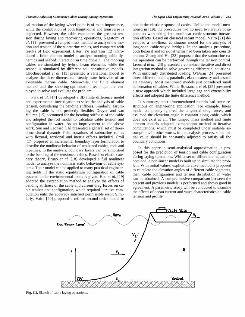
Fig. (1). Sketch of cable laying operations.
284 The Open Civil Engineering Journal, 2013, Volume 7 Yang et al.
2. THEORETICAL MODEL
2.1. Problem Considered
The present theory can be used to solve some relevant problems about submarine cable in engineering application. Based on the calculations, tension distribution and cable con-figuration in water during laying operations can be obtained. The problem considered in this study is illustrated in Fig. (1). In the figure, is current velocity, is cable ship motion, H is water depth, is payout-rate, and is self-weight of the cable.
In this study, the tension analysis of submarine cable is based on the following assumptions:
Continuous: submarine cable is considered continuous in the analysis;
Inextensible: because of relatively high axial stiffness, cable extensible can be neglected in the analysis;
Flexible: bending stiffness is neglectful;
Cable and body dimensions are small compared to inci-dent wave length, so calculation of hydrodynamic forces by the Morison equation is valid;
The seawater is ideal liquid: irrational, inviscid and in-compressible;
Submarine cable: rotational motions are not considered, cable weight per unit length is constant and cross-sectional area is uniform;
The submarine cable is taken to be fully immersed in water, no portion of cable above the seawater level is
taken into consideration in this analysis;
Submarine cable is subjected to uni-axial tension with-out flexure, shear or torsion;
Drag forces on the cable are taken from the relative ve-locity form of the Morison equation, and the independ-ence principle for normal and tangential drags is in-voked;
The drag coefficients and in the Morison equation are Reynolds number dependent, but in this paper, they are taken as constant values;
2.2. Equilibrium Equations for the Submarine Cable in Water
When the submarine cables are laid from the laying wheel point on a cable ship, there are at least four compo-nents that contribute to the tensional forces along the subma-rine cable.
Gravity forces, which is due to submarine cable self-weight;
Buoyancy force, which is equal to the weight of its dis-placed fluid;
Drag forces, which are due to steady current and current profile;
Residual bottom tension, which translates to an extra tensional force during the laying operations;
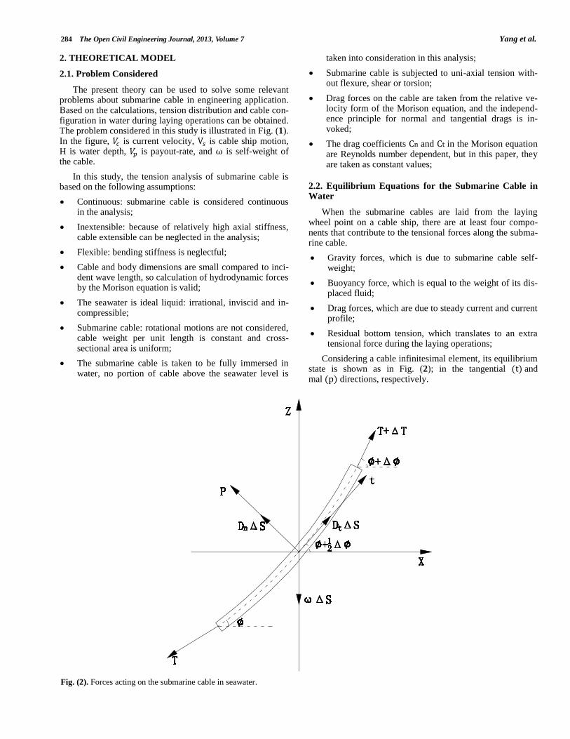
Considering a cable infinitesimal element, its equilibrium state is shown as in Fig. (2); in the tangential and mal directions, respectively.
Fig. (2). Forces acting on the submarine cable in seawater.
Tension Analysis of Submarine Cables During Laying Operations The Open Civil Engineering Journal, 2013, Volume 7 285
(1)
(2)
where is the tension force at a i-th point; is self-weight of submarine cable per unit length in water; and are the difference tension and elevation angle between i-th and i+1-th points; is the arc length of cable element; and and are drag forces in tangential and normal directions, respectively.
When the element length tends to be infinitely small (i.e., approaching to a point), , then , and , then (1) and (2) can be simplified as
,
(3)
Then tangential and normal drag forces per unit length in seawater can be acquired through Morison equation
,
(4)
where and are drag coefficients in tangential and nor-mal directions, which mainly depend on the Reynolds num-ber and the roughness of submarine cable surface. is den-sity of seawater, is effective diameter of submarine cable; and are relative velocity components in normal and tangential direction, respectively. In this paper, we adopt and , respectively [21].
In the Morison equation, the relative velocity is taken into consideration,
where
, (5)
where is the relative velocity between ocean current and cable ship motion in the sailing direction.
Since the tangential force is relative small, in the first step of tension calculation, the tangential force can be ne-glected, or . Then, (3) can be reduced to
,
(6)
where is the submarine cable tension at an arbitrary point
corresponding to elevation angle with .
Based on (6), we can obtain the following expression:
(7)
The result of (7) is integrated over the cable element:
(8)
And then tension of submarine cable can be expressed as:
(9)
Where and
.
where and are the tension and elevation angle at the touchdown point (TDP), respectively. The relationship be-tween submarine cable tension and water depth can be ob-
tained through the following equilibrium equation:
(10)
Based on (7) and (8), the relation between cable elevation angle and water depth can be expressed as
(11)
It is noted that the elevation angle determined from (9)
doesn’t consider the tangential force, i.e., . There-
fore, we can further estimate the elevation angle for the case
of by
.
Once the elevation angle ( ) at arbitrary point (with ) is obtained, the cable tension distribution can be determined based on (3),
(12)
2.3. Tension Calculation of a Submarine Cable During Laying Operations
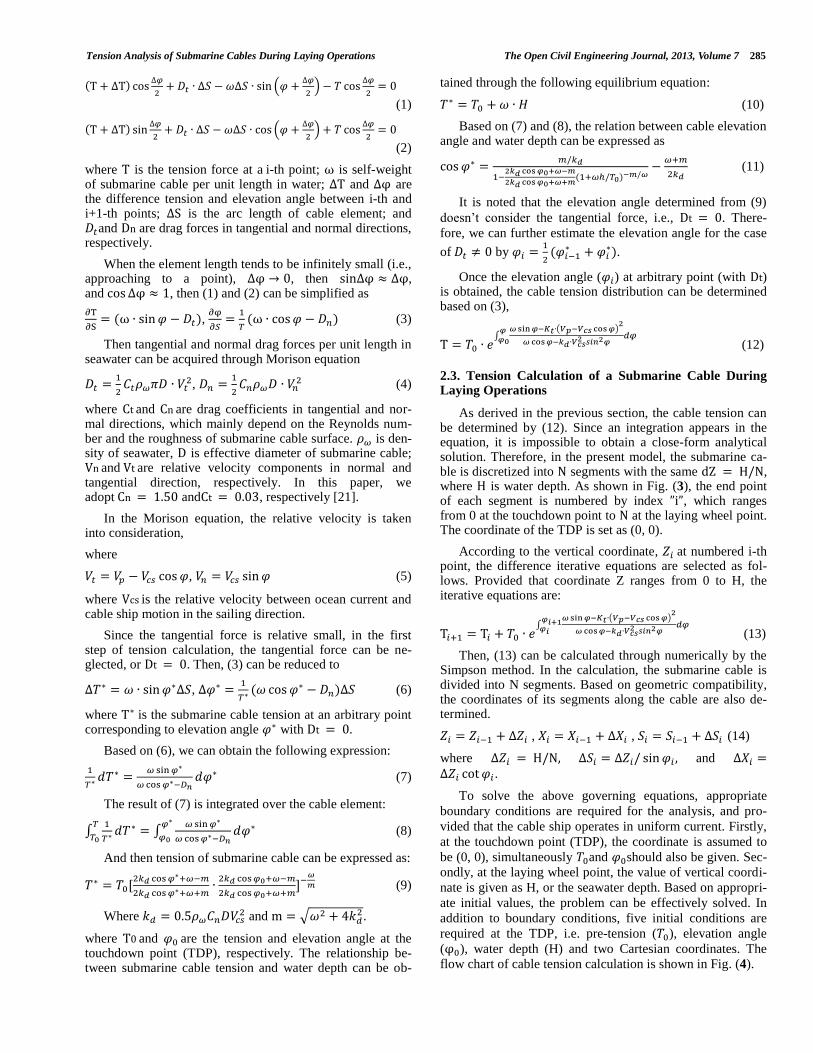
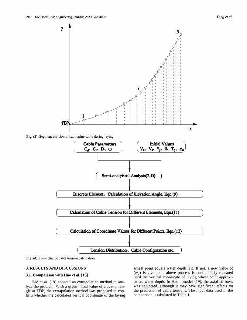
As derived in the previous section, the cable tension can be determined by (12). Since an integration appears in the equation, it is impossible to obtain a close-form analytical solution. Therefore, in the present model, the submarine ca-ble is discretized into segments with the same , where is water depth. As shown in Fig. (3), the end point of each segment is numbered by index , which ranges from 0 at the touchdown point to at the laying wheel point. The coordinate of the TDP is set as (0, 0).
According to the vertical coordinate, at numbered i-th point, the difference iterative equations are selected as fol-lows. Provided that coordinate Z ranges from 0 to H, the iterative equations are:
(13)
Then, (13) can be calculated through numerically by the Simpson method. In the calculation, the submarine cable is divided into N segments. Based on geometric compatibility, the coordinates of its segments along the cable are also de-termined.
, , (14)
where and .
To solve the above governing equations, appropriate
boundary conditions are required for the analysis, and pro-
vided that the cable ship operates in uniform current. Firstly,
at the touchdown point (TDP), the coordinate is assumed to
be (0, 0), simultaneously and should also be given. Sec-
ondly, at the laying wheel point, the value of vertical coordi-
nate is given as H, or the seawater depth. Based on appropri-
ate initial values, the problem can be effectively solved. In
addition to boundary conditions, five initial conditions are
required at the TDP, i.e. pre-tension ( ), elevation angle
( ), water depth (H) and two Cartesian coordinates. The
flow chart of cable tension calculation is shown in Fig. (4).
286 The Open Civil Engineering Journal, 2013, Volume 7 Yang et al.
3. RESULTS AND DISCUSSIONS
3.1. Comparison with Hao et al. [19]
Hao et al. [19] adopted an extrapolation method to ana-lyze the problem. With a given initial value of elevation an-gle at TDP, the extrapolation method was proposed to con-firm whether the calculated vertical coordinate of the laying
wheel point equals water depth ( ). If not, a new value of ( ) is given, the above process is continuously repeated until the vertical coordinate of laying wheel point approxi-mates water depth. In Hao’s model [19], the axial stiffness was neglected, although it may have significant effects on the prediction of cable tensions. The input data used in the comparison is tabulated in Table 1.
Fig. (3). Segment division of submarine cable during laying.
Fig. (4). Flow char of cable tension calculation.

Tension Analysis of Submarine Cables During Laying Operations The Open Civil Engineering Journal, 2013, Volume 7 287
Based on the input data given in Table 1, the origin of Cartesian coordinate is located at the touchdown point on seabed. Cable tension and Cartesian coordinates are calculat-ed, and the results are shown in Fig. (5). In the figure, the solid line represents the present theory and the dash line is for Hao et al. [19]. Fig. (5a) shows that cable configuration obtained from both models are almost identical. It is found in Fig. (5b) that cable tension calculated from the present theo-ry is larger than that from Hao et al. [19] except for a very small portion around the seabed surface. The difference be-comes slightly larger as X increases. At the water surface point, tension forces are 16.77 kN from [18] and 16.93 kN from the present theory, respectively.
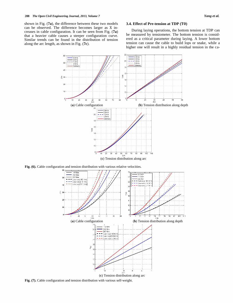
3.2. Effect of the Relative Velocity Between Currents and Cable Ship Motion
The conventional method used in the tensional analysis of the cables in marine environment was based on catenary theory [26]. In the approach, the cable is following a catena-ry line from the exit point on the laying wheel down to the TDP on the seafloor, by assuming the cable laying vessel lays cable in calm waters with constant speed over a horizon-tal seafloor. The cable is assumed to have no bending stiff-ness and no drag while moving through the water. In the following examples, we will compare the present model with the conventional catenary theory through a parametric study. The input data are listed in Table 2 unless they are specified.
To have a deeper insight into the submarine cable behav-ior during laying operation, the effect of relative motion is studied here. In this example, five cases (catenary theory, 0.4 m/s, 0.8 m/s, 1.2 m/s, 1.6 m/s) are considered. As shown in Fig. (6), the difference between the present theory and catenary theory [26] can be observed. By comparing the calculated results, it can be observed that cable configuration of catenary theory is steeper than any relative velocity. With-in 4.5 m above the seabed surface, cable profiles almost overlap, and the difference becomes larger as the relative velocity decreases. Similarly, the trend can be seen from Fig. (6b & c). However, the effects of relative velocity on the cable configuration are more important than that on tension distribution.
3.3. Effect of Cable Self-weight ( )
Cable weight per unit length in water is another key pa-rameter in the analysis of cable behavior during laying op-erations. Three different cable weights ( =145.0 N/m, 215.0 N/m, 297.0 N/m) are considered in this example. The corre-sponding mass of unit length, weight of cables in air, and effective diameter of cable are given in Table 3.
Example presented in Fig. (7) shows that the influence of cable weight per unit length in water on tension distribution along water depth between two models are insignificant. Compared with the tension distribution, the cable weight has a more significant influence on cable configuration. As
Table 1. Input Data for Comparison
Parameter Value
Effective Diameter ( ) 38 mm
Water depth ( ) 20.0 m
Cable weight in water ( ) 76.45 N/m
Normal drag coefficient ( ) 1.2
Tangential drag coefficient ( ) 0.024
Pre-tension ( ) 15.4 kN
Relative velocity ( ) 1.2 m/s
Table 2. Input Data for the Parametric Study
Parameter Value
Effective Diameter ( ) 98 mm or various
Water depth ( ) 60.0 m
Cable weight in water ( ) 209 N/m or various
Normal drag coefficient ( ) 1.50
Tangential drag coefficient ( ) 0.03
Pre-tension ( ) 8 kN or various
relative velocity ( ) 1.2 m/s or various
Cable pay-out rate ( ) 0.8 m/s or various
(a) Cable Configuration (b) Tension Distribution
Fig. (5). Cable configuration and tension distribution from the present model and Hao et al [19].
288 The Open Civil Engineering Journal, 2013, Volume 7 Yang et al.
shown in Fig. (7a), the difference between these two models can be observed. The difference becomes larger as in-creases in cable configuration. It can be seen from Fig. (7a) that a heavier cable causes a steeper configuration curve. Similar trends can be found in the distribution of tension along the arc length, as shown in Fig. (7c).
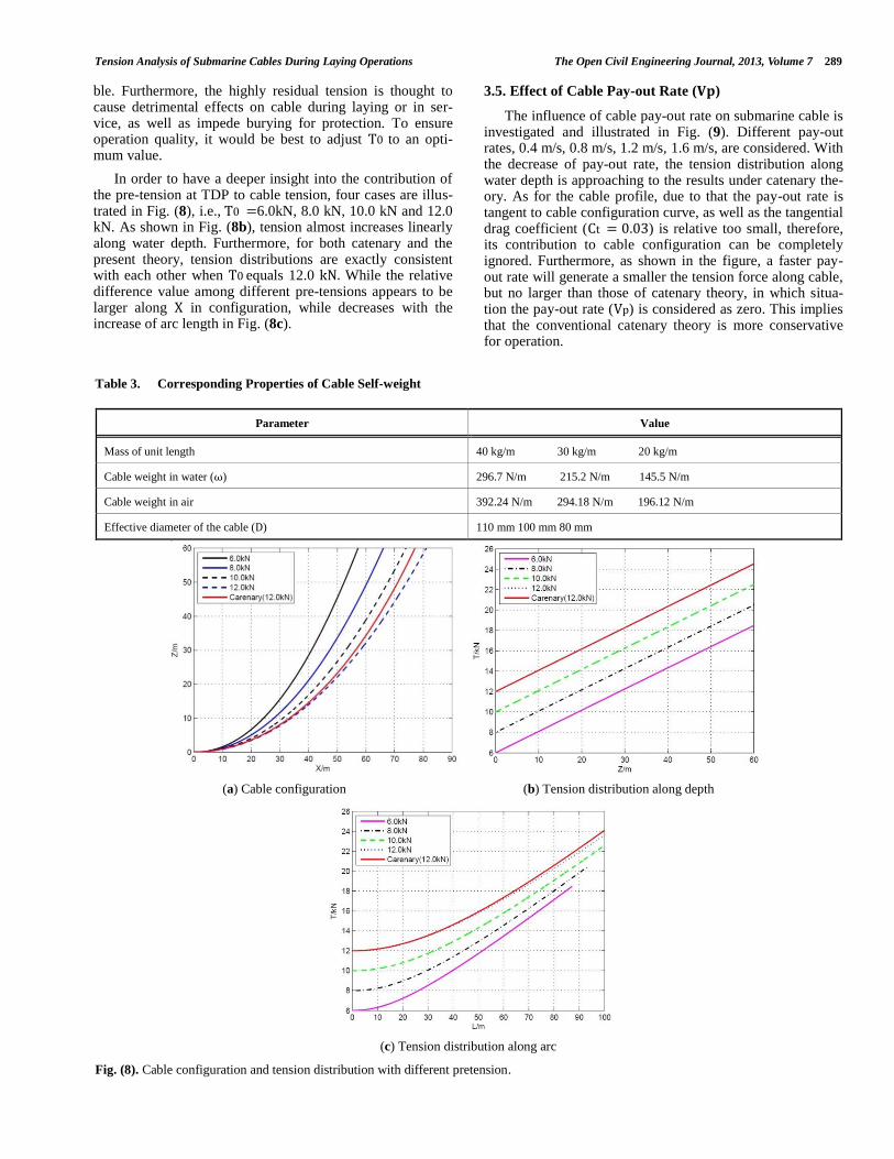
3.4. Effect of Pre-tension at TDP ( )
During laying operations, the bottom tension at TDP can be measured by tensiometer. The bottom tension is consid-ered as a critical parameter during laying. A lower bottom tension can cause the cable to build lops or snake, while a higher one will result in a highly residual tension in the ca-
(a) Cable configuration (b) Tension distribution along depth
(c) Tension distribution along arc
Fig. (6). Cable configuration and tension distribution with various relative velocities.
(a) Cable configuration (b) Tension distribution along depth
(c) Tension distribution along arc
Fig. (7). Cable configuration and tension distribution with various self-weight.
Tension Analysis of Submarine Cables During Laying Operations The Open Civil Engineering Journal, 2013, Volume 7 289
ble. Furthermore, the highly residual tension is thought to cause detrimental effects on cable during laying or in ser-vice, as well as impede burying for protection. To ensure operation quality, it would be best to adjust to an opti-mum value.
In order to have a deeper insight into the contribution of the pre-tension at TDP to cable tension, four cases are illus-trated in Fig. (8), i.e., 6.0kN, 8.0 kN, 10.0 kN and 12.0 kN. As shown in Fig. (8b), tension almost increases linearly along water depth. Furthermore, for both catenary and the present theory, tension distributions are exactly consistent with each other when equals 12.0 While the relative difference value among different pre-tensions appears to be larger along in configuration, while decreases with the increase of arc length in Fig. (8c).
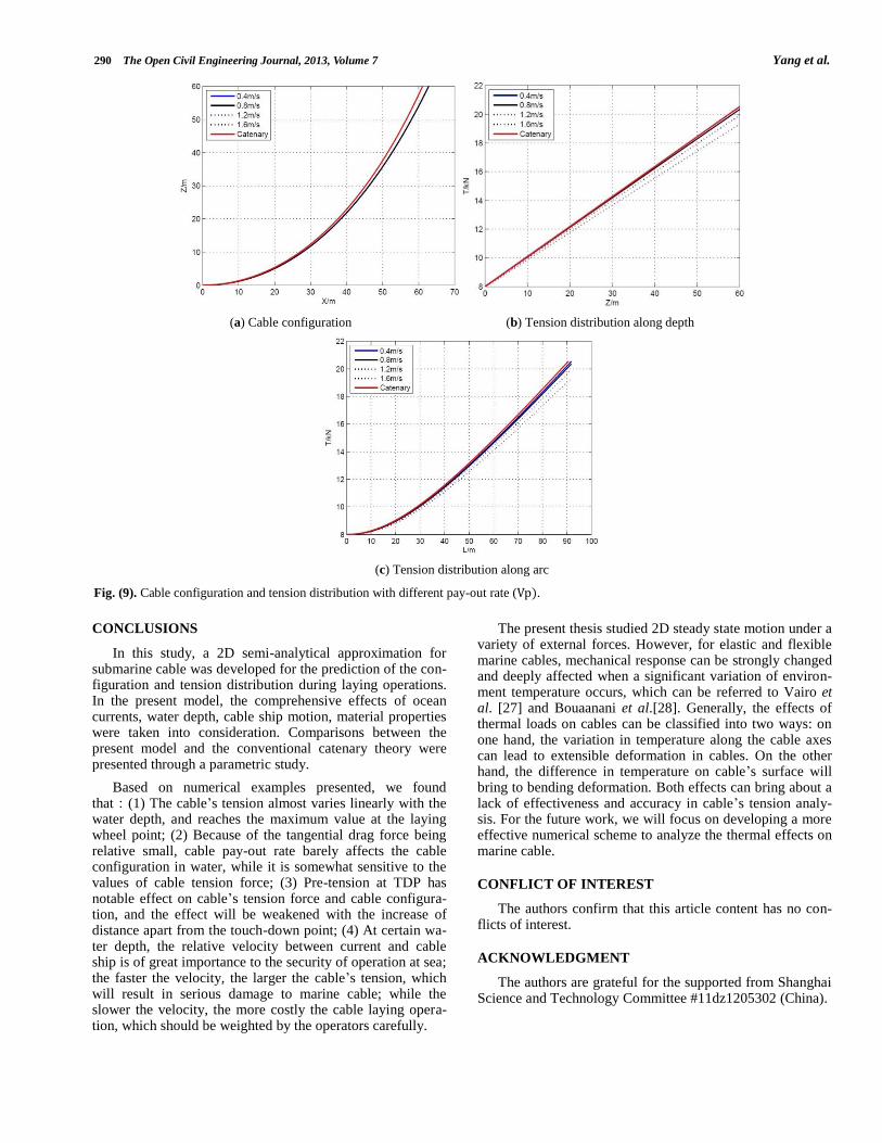
3.5. Effect of Cable Pay-out Rate ( )
The influence of cable pay-out rate on submarine cable is investigated and illustrated in Fig. (9). Different pay-out rates, 0.4 m/s, 0.8 m/s, 1.2 m/s, 1.6 m/s, are considered. With the decrease of pay-out rate, the tension distribution along water depth is approaching to the results under catenary the-ory. As for the cable profile, due to that the pay-out rate is tangent to cable configuration curve, as well as the tangential drag coefficient ( ) is relative too small, therefore, its contribution to cable configuration can be completely ignored. Furthermore, as shown in the figure, a faster pay-out rate will generate a smaller the tension force along cable, but no larger than those of catenary theory, in which situa-tion the pay-out rate ( ) is considered as zero. This implies that the conventional catenary theory is more conservative for operation.
Table 3. Corresponding Properties of Cable Self-weight
Parameter Value
Mass of unit length 40 kg/m 30 kg/m 20 kg/m
Cable weight in water ( ) 296.7 N/m 215.2 N/m 145.5 N/m
Cable weight in air 392.24 N/m 294.18 N/m 196.12 N/m
Effective diameter of the cable ( ) 110 mm 100 mm 80 mm
(a) Cable configuration (b) Tension distribution along depth
(c) Tension distribution along arc
Fig. (8). Cable configuration and tension distribution with different pretension.
290 The Open Civil Engineering Journal, 2013, Volume 7 Yang et al.
CONCLUSIONS
In this study, a 2D semi-analytical approximation for submarine cable was developed for the prediction of the con-figuration and tension distribution during laying operations. In the present model, the comprehensive effects of ocean currents, water depth, cable ship motion, material properties were taken into consideration. Comparisons between the present model and the conventional catenary theory were presented through a parametric study.
Based on numerical examples presented, we found that:(1) The cable’s tension almost varies linearly with the water depth, and reaches the maximum value at the laying wheel point; (2) Because of the tangential drag force being relative small, cable pay-out rate barely affects the cable configuration in water, while it is somewhat sensitive to the values of cable tension force; (3) Pre-tension at TDP has notable effect on cable’s tension force and cable configura-tion, and the effect will be weakened with the increase of distance apart from the touch-down point; (4) At certain wa-ter depth, the relative velocity between current and cable ship is of great importance to the security of operation at sea; the faster the velocity, the larger the cable’s tension, which will result in serious damage to marine cable; while the slower the velocity, the more costly the cable laying opera-tion, which should be weighted by the operators carefully.
The present thesis studied 2D steady state motion under a variety of external forces. However, for elastic and flexible marine cables, mechanical response can be strongly changed and deeply affected when a significant variation of environ-ment temperature occurs, which can be referred to Vairo et al. [27] and Bouaanani et al.[28]. Generally, the effects of thermal loads on cables can be classified into two ways: on one hand, the variation in temperature along the cable axes can lead to extensible deformation in cables. On the other hand, the difference in temperature on cable’s surface will bring to bending deformation. Both effects can bring about a lack of effectiveness and accuracy in cable’s tension analy-sis. For the future work, we will focus on developing a more effective numerical scheme to analyze the thermal effects on marine cable.
CONFLICT OF INTEREST
The authors confirm that this article content has no con-flicts of interest.
ACKNOWLEDGMENT
The authors are grateful for the supported from Shanghai Science and Technology Committee #11dz1205302 (China).
(a) Cable configuration (b) Tension distribution along depth
(c) Tension distribution along arc
Fig. (9). Cable configuration and tension distribution with different pay-out rate ( .
Tension Analysis of Submarine Cables During Laying Operations The Open Civil Engineering Journal, 2013, Volume 7 291
REFERENCES
[1] E. Zajac, “Dynamics and kinematics of the laying and recovery of submarine cable”, Bell Syst. Tech. J., vol. 36, no. 5, pp. 1129–1207, 1957.
[2] N. Yoshizawa and T. Yabuta, “Study on submarine cable tension during laying”, IEEE J. Oceanic Eng., vol. 8, no. 4, pp. 293–299, 1983.
[3] Y. Wang, X. Bian, X. Zhang and W. Xie, “A study on the influence of cable tension on the movement of cable laying ship”, Oceans 2010, pp. 1–8, 2010.
[4] M. Vaz and M. Patel, “Transient behaviour of towed marine cables in two dimensions”, Appl. Ocean Res., vol. 17, no. 3, pp. 143–153, 1995.
[5] M. Patel and M. Vaz, “The transient behaviour of marine cables being laid–the two-dimensional problem”, Appl. Ocean Res., vol. 17, no. 4, pp. 245–258, 1995.
[6] M. Vaz, J. Witz and M. Patel, “Three dimensional transient analy-sis of the installation of marine cables”, Acta Mech., vol. 124, no. 1-4, pp. 1–26, 1997.
[7] M. Vaz and M. Patel, “Three-dimensional behaviour of elastic marine cables in sheared currents”, Appl. Ocean Res., vol. 22, no. 1, pp. 45–53, 2000.
[8] F. Wang, G. Huang and D. Deng, “Steady state analysis of towed marine cables”, J. Shanghai Jiaotong Univ. (Science), vol. 13, pp. 239–244, 2008.
[9] J. Prpic and R. Nabergoj, “Dynamic tension of marine cables dur-ing laying operations in irregular waves”, Int. Shipbuild. Prog., vol. 48, no. 2, pp. 149–167, 2001.
[10] J. Prpic and R. Nabergoj, “Nonlinear dynamics of an elastic cable during laying operations in rough sea”, Appl. Ocean Res., vol. 27, no. 6, 255–264, 2005.
[11] O. Nagatomi, M. Nakamura and W. Koterayama, “Dynamic simu-lation and field experiment of submarine cable during laying and recovery”, The Twelfth (2002) International Offshore and Polar Engineering Conference (ISOPE2002), pp. 255–262, 2002.
[12] L. Yu and J.-H. Tan, “Numerical investigation of seabed interac-tion in time domain analysis of mooring cables”, J. Hydrodyn., Ser. B, vol. 18, no. 4, pp. 424–430, 2006.
[13] S. Chucheepsakul, N. Srinil and P. Petchpeart, “A variational ap-proach for three-dimensional model of extensible marine cables with specified top tension”, Appl. Math. Model., vol. 27,no. 10, pp. 781–803, 2003.
[14] H. Park, D. Jung and W. Koterayama, “A numerical and experi-mental study on dynamics of a towed low tension cable”, Appl. Ocean Res., vol. 25, no. 5, pp. 289–299, 2003.
[15] T. Dreyer and J. van Vuuren, “A comparison between continuous and discrete modelling of cables with bending stiffness”, Appl. Math. Model., vol. 23, no. 7, pp. 527–541, 1999.
[16] Y. Sun and J. W. Leonard, “Dynamics of ocean cables with local low-tension regions”, Ocean Eng., vol. 25, no. 6, pp. 443–463, 1988.
[17] J. Croll, “Bending boundary layers in tensioned cables and rods”, Appl. Ocean Res., vol. 22, no. 4, pp. 241–253, 2000.
[18] D. Bruno and A. Leonardi, “Nonlinear structural models in cable-way transport systems”, Simul Pract. Theory, vol. 7, no. 3, pp. 207–218, 1999.
[19] C. Hao, Y-F. Zhang, B. Teng, W. Xu and H.-T. Zhao, “Analysis of elastic single mooring cable system with different elasticity and ve-locity distribution”, J. Marine Sci., vol. 24, no. 3, pp. 90–95, 2006.
[20] G. Vairo, “A closed-form refined model of the cable’s nonlinear response in cable-stayed structures”, Mech. Adv. Mater. Struct., vol. 16, pp. 456–466, 2009.
[21] G. Vairo, “A quasi-secant continuous model for the analysis of long-span cable-stayed bridges”, Meccanica, vol. 43, pp. 237–250, 2008.
[22] T. Zhang and X. Hu, “Tension analysis in submarine cable laying”, Ship Boat, vol. 3, pp. 15–20, 2009.
[23] J. Leonard, S. Karnoski and R. Stephen, “Simulation of tension controlled cable deployment”, Appl. Ocean Res., vol. 12, no. 1, pp. 34–42, 1990.
[24] W. O’Brian, “General solution of suspended cable problem”, J. Struct. Div. ASCE, vol. 93, pp. 1-126, 1967.
[25] N. Bouaanani and M. Ighouba, “A novel scheme for large deflec-tion analysis of suspended cables made of linear or nonlinear elas-tic materials”, Adv. Eng. Soft., vol. 42, no. 12, pp. 1009-1019, 2011.
[26] T. Worzyk, Submarine power cables: design, installation, repair, environmental aspects, Springer, Heidelberg, 2009.
[27] G. Vairo and S. Montassar, “Mechanical Modelling of Stays under Thermal Loads”, Lect. Notes Appl. Comput. Mech., vol. 61, pp. 481-498, 2012.
[28] N. Bouaanani and P. Marcuzzi, “Finite difference thermoelastic analysis of suspended cables including extensibility and large sag effects”, J. Thermal Stresses, vol. 34, no. 1, pp. 18-50, 2011.
Received: August 21, 2013 Revised: November 23, 2013 Accepted: November 25, 2013
© Yang et al.; Licensee Bentham Open.
This is an open access article licensed under the terms of the Creative Commons Attribution Non-Commercial License (http://creativecommons.org/licenses/
by-nc/3.0/) which permits unrestricted, non-commercial use, distribution and reproduction in any medium, provided the work is properly cited.