Tennessee Valley Authority (TVA) internal agency records which
Tennessee Valley Authority, Post Office Box 2000, Spring City, Tennessee 37381-2000
William J. MuselerSite Vice President, Watts Bar Nuclear Plant
OCT 2 5 1993
U.S. Nuclear Regulatory CommissionATTN: Document Control DeskWashington, D.C. 20555
Gentlemen:
In the Matter of the Application ofTennessee Valley Authority
) Docket Nos. 50-39050-391
WATTS BAR NUCLEAR PLANT (WBN) - UNITS 1 AND 2 - SUPPLEMENTAL INFORMATION -U-BOLT SUPPORT STABILITY EVALUATION PROGRAM (TAC NOS. M79718 AND M80345)
Reference 1) TVA letter to NRC, April 8, 1993, Response to NRC questions -WBN U-Bolt Evaluation Program
2) TVA letter to NRC, June 21, 1993, Response to NRC questions -U-Bolt Support Stability Evaluation Program
3) NRC letter to TVA, September 13, 1993, Safety Evaluation onUse of U-Bolts
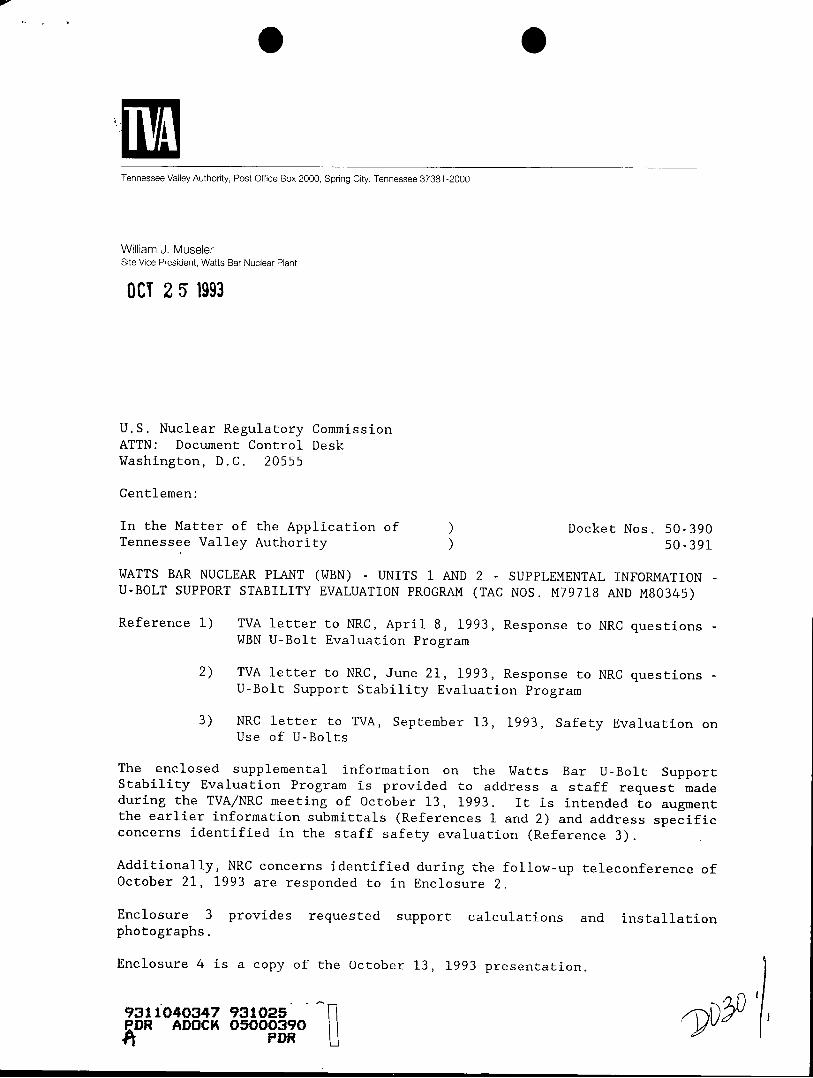
The enclosed supplemental information on the Watts Bar U-Bolt SupportStability Evaluation Program is provided to address a staff request madeduring the TVA/NRC meeting of October 13, 1993. It is intended to augmentthe earlier information submittals (References 1 and 2) and address specificconcerns identified in the staff safety evaluation (Reference 3).
Additionally, NRC concerns identified during the follow-up teleconference ofOctober 21, 1993 are responded to in Enclosure 2.
Enclosure 3 provides requested support calculations and installationphotographs.
Enclosure 4 is a copy of the October 13, 1993 presentation.
931i040347 931025PDR ADOCK 05000390A PDR
/> I1

U.S. Nuclear Regul ory CommissionPage 2
GCO 25 1993
It is TVA's understanding that this material will provide the basis for thestaff to promptly reissue the U-Bolt SER, approving the TVA program. If thisis not the case or if there are any questions on this information, pleasecontact me at (615)-365-8767.
Very truly yours,
William J. Museler
Enclosurescc (Enclosures):
NRC Resident InspectorWatts Bar Nuclear PlantRt. 2, P.O. Box 700Spring City, Tennessee 37381
Mr. P. S. Tam, Senior Project ManagerU.S. Nuclear Regulatory CommissionOne White Flint North11555 Rockville PikeRockville, Maryland 20852
U.S. Nuclear Regulatory CommissionRegion II101 Marietta Street, NW, Suite 2900Atlanta, Georgia 30323

ENCLOSURE 1
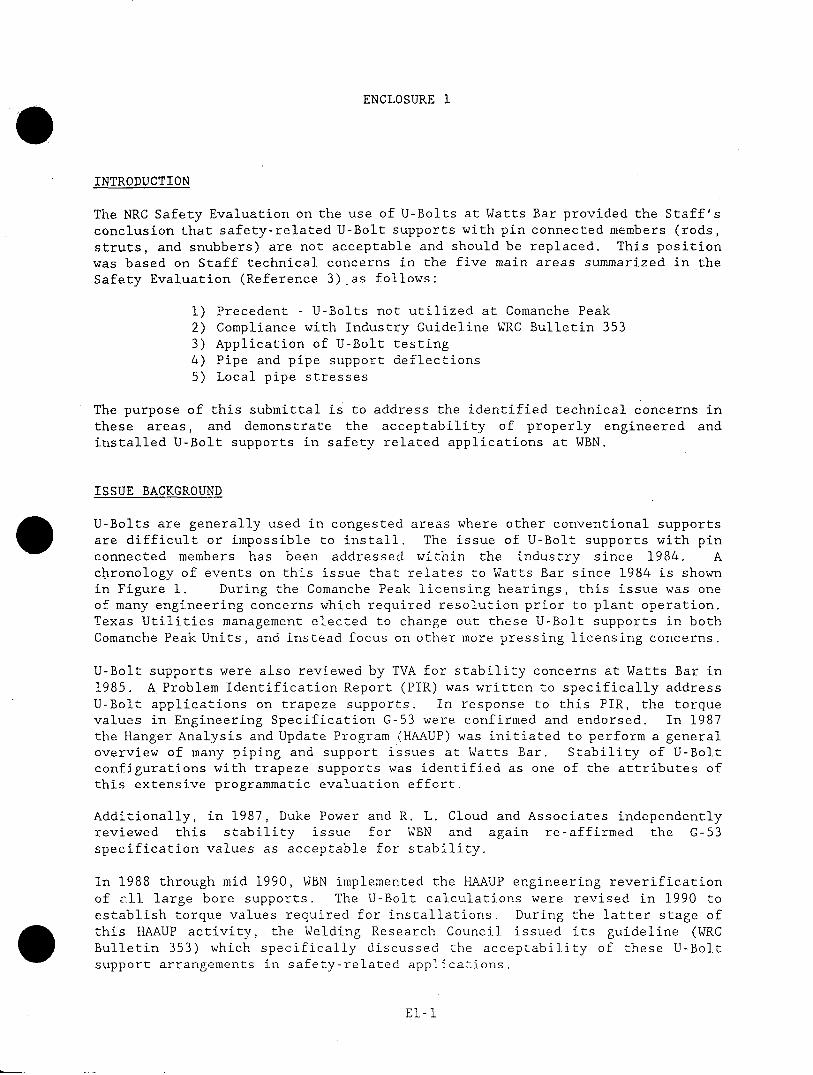
INTRODUCTION
The NRC Safety Evaluation on the use of U-Bolts at Watts Bar provided the Staff'sconclusion that safety-related U-Bolt supports with pin connected members (rods,struts, and snubbers) are not acceptable and should be replaced. This positionwas based on Staff technical concerns in the five main areas summarized in theSafety Evaluation (Reference 3) as follows:
1) Precedent - U-Bolts not utilized at Comanche Peak2) Compliance with Industry Guideline WRC Bulletin 3533) Application of U-Bolt testing4) Pipe and pipe support deflections5) Local pipe stresses
The purpose of this submittal is to address the identified technical concerns inthese areas, and demonstrate the acceptability of properly engineered andinstalled U-Bolt supports in safety related applications at WBN.
ISSUE BACKGROUND
U-Bolts are generally used in congested areas where other conventional supportsare difficult or impossible to install. The issue of U-Bolt supports with pinconnected members has been addressed within the industry since 1984. Achronology of events on this issue that relates to Watts Bar since 1984 is shownin Figure 1. During the Comanche Peak licensing hearings, this issue was oneof many engineering concerns which required resolution prior to plant operation.Texas Utilities management elected to change out these U-Bolt supports in bothComanche Peak Units, and instead focus on other more pressing licensing concerns.
U-Bolt supports were also reviewed by TVA for stability concerns at Watts Bar in1985. A Problem Identification Report (PIR) was written to specifically addressU-Bolt applications on trapeze supports. In response to this PIR, the torquevalues in Engineering Specification C-53 were confirmed and endorsed. In 1987the Hanger Analysis and Update Program (HAAUP) was initiated to perform a generaloverview of many piping and support issues at Watts Bar. Stability of U-Boltconfigurations with trapeze supports was identified as one of the attributes ofthis extensive programmatic evaluation effort.
Additionally, in 1987, Duke Power and R. L. Cloud and Associates independentlyreviewed this stability issue for WBN and again re-affirmed the G-53specification values as acceptable for stability.
In 1988 through mid 1990, WBN implemented the HAAUP engineering reverificationof Lll large bore supports. The U-Bolt calculations were revised in 1990 toestablish torque values required for installations. During the latter stage ofthis HAAUP activity, the Welding Research Council issued its guideline (WRCBulletin 353) which specifically discussed the acceptability of these U-Boltsupport arrangements in safety-related applications.
El-l
During the 1992 WBN IDI, a U-Bolt trapeze assembly rotated under personnelweight. On investigation of this issue, the 1990 torquing calculation was foundto be in error. This calculation reduced the required torque to lower valuesthan General Construction Specification requirements. A correct torque wasrecalculated, the U-Bolt retorqued, and in situ tested during the IDI. Undercorrect torque, the U-Bolt exhibited no rotation under applied load. Inaddition, a complete extent of condition review was performed to identify U-Boltcalculations which had similar errors. TVA initiated a program of reverificationand evaluation of U-Bolts used in trapeze, single strut, or snubber application.
Four subsequent information submittals addressing NRC questions and technicalconcerns were processed prior to the recent issuance of the Staff's SafetyEvaluation Report (SER). As indicated earlier, each of the identified SERconcerns will be discussed within this submittal. Additionally, follow-upquestions received during a TVA/NRC teleconference of October 21, 1993 areaddressed.
E1-2

ISSUE BACKGROUNT
1984 * COMANCHE PEAK U-BOLT CINCHING ISSUE- TU DECISION TO ELIMINATE ALL U-BOLTS AT COMANCHE PEAK
1985 PIR WRITTEN AT WBN ON U-BOLT APPLICATIONS ON TRAPEZESUPPORTS
- FOLLOW-UP TVA CALC ENDORSED G-53 SPECIFICATION TORQUE
1987 * WBN - HAAUP PROGRAM IDENTIFIED- U-BOLT W/TRAPEZE SUPPORT STABILITY WAS IDENTIFIED
- DUKE POWERICLOUD CALCS INDEPENDENTLY CONCLUDED G-53SPECIFICATION VALUES ACCEPTABLE FOR STABILITY
1989& - WBN - ENGINEERING REVERIFICATION OF ALL LARGE BORE SUPPORTS
1990 - FOR SOME SUPPORTS, RECALCULATED MIN. TORQUE VALUESLOWER THAN SPEC G-53 VALUES
* WRC BULLETIN 353 ISSUED1990
1992 * WBN - IDI INSPECTIONS- U-BOLTS TRAPEZE ROTATED UNDER PERSONNEL WEIGHT
- 1990 CALCULATION ESTABLISHING TORQUE FOUND TO BE INERROR
- CORRECT TORQUE WOULD HAVE PREVENTED ROTATION(DEMONSTRATED BY FIELD TEST DURING IDI)
1993 * FOUR INFORMATION SUBMITTALS FORWARDED IN RESPONSE TONRC QUESTIONS
- TWO TECHNICAL MEETINGS
Figure 1
WPC BULLETI/V 353
T I - - - - - - - -T T s~--I-* --
USE OF U-BOLT IN A RESTRAINT-TYPE
TRAPEZE HANGER
LII
ALTERNATE USE OF U-BOLT IN A RESTRAINT-TYPE
TRAPEZE Hl.ANGER
F IG. 6 - TIGHT F!T
P-I '
~ L) J% 7 I I r> i | o t> '] I
U-BOLT PROPERLY TORQUED
STABLE
U-BOLT NOT PROP-RLY TOROUEDU N'S S A S L E
FIG. 9 - TIGHT FIT U-BOLTS IN TRAPEZE ASSEMBE LIES
Figure 2
I
- "Z7P Qr. P � �
I �� , 3 - -)0

WRC 353 APPLICATION
DO'S ADDRESSED BY
ENSURE METHOD OF ATTACHING TO EVALUATION METHOD PLUS PRELOAD
PIPE PREVENTS SLIDING AND
ROTATING
ENSURE METHOD PROVEN THRU BELLEVILLE WASHERS ADDRESS ISSUE
EXPERIENCE OR TESTED TO SHOW
"HOLDING POWER" OVER TIME
ENSURE METHOD DOES NOT INDUCE CRITERIA AND EVALUATION METHOD
EXCESSIVE LOCALIZED STRESSES ADDRESS ISSUE
(CONCERN MAINLY WITH THIN
WALLED PIPE) (SCHEDULE 10) (NO U-BOLTS ON SCHEDULE 10 PIPE)
DON'TS ADDRESSED BY
DON'T WELD TO PIPE NO WELDING TO PIPE TO ADDRESS U-
BOLTS
DON'T FORGET SNUBBERS EXTEND PRELOAD OF U-BOLT PLUS ADDITION
UNDER THEIR OWN WEIGHT AND OF BELLEVILLE WASHERS
ATTACHMENT TO PIPE MUST
MAINTAIN SUPPORT IN A STABLE
CONDITION
Figure 3

SER ISSUE
DISCUSSIONS
1. COMANCHE PEAK PRECEDENCE
Texas Utilities (TU) decided to delete U-Bolt configurations at ComanchePeak as one aspect of the plant's piping evaluation and upgrade.Investigations performed by Westinghouse (W) for TU and furtherdeveloped by R. L. Cloud and Associates, Incorporated (RCLA) concludedthat properly engineered U-Bolts can perform their intended designfunctions. However, the final TU technical program for U-Boltacceptance was not submitted to the Nuclear Regulatory Commission (NRC)for review. After examining this program, TVA found it to betechnically defensible and appropriate for application at Watts BarNuclear Plant (WBN). The WBN program has enhanced the W/RCLA programand is implementing improvements to this program.
Further, based on our informal survey, eight plants (11 Units) have beenlicensed after the Comanche Peak issue was raised that have similarapplications. Also, based on our informal review, approximately 50percent of the operating plants surveyed utilize U-Bolts in the samekind of applications as WBN.
El-4

2. COMPLIANCE WITH WELDING RESEARCH COUNCIL(WRQ) BULLETIN 353
While it is emphasized that this WRC Bulletin is not a Regulatory
requirement, WRC 353 does provide industry guidance for proper U-Bolt
usage including specified DOs and DON'Ts for the assurance of a stable
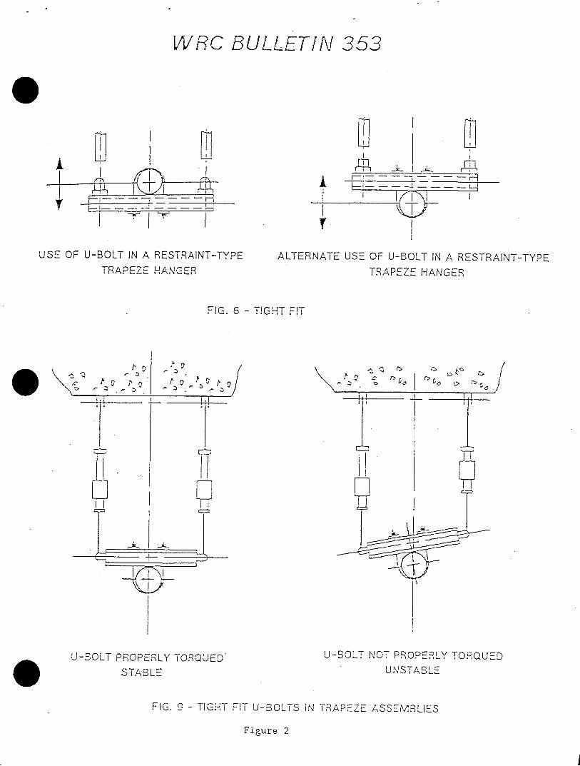
support design. Guidance in the use of tight fit U-Bolts in trapeze
support assemblies is provided in the WRC Bulletin 353 on pipe supports.
This Bulletin was issued in May 1990 which was the latter stage of theHAAUP program. Section 2.4.5.3 of the WRC Bulletin states "Tight-FitU-Bolts are often used in support trapeze assemblies to provide support
in one direction for rod hangers and two directions for struts andsnubbers. The latter design is not recommended (refer to Section 2.4.1)for stability reasons. In these types of applications the U-Bolt isprimarily in tension. This type of support can be used for all sizesof pipe. See figures 6 and 9."
The WBN supports comply with the WRC Bulletin guidelines. The rodhangers are used to carry the loading in one direction (tension) onlywhich conforms to figure 6 in the WRC bulletin. U-Bolts used inconjunction with struts or snubbers are designed to carry the loading
in either a vertical or lateral direction only. These assumptions areconsistent with how the supports are modeled in the piping analysis of
the Bulletin. Guidance is provided in Figures 6 and 9 of the Bulletin,(see Figure 2) and in Section 2.4.1 when they are used. Theseprovisions are in the form of "Do's and Don'ts" and the WBN supportscomply. Figure 3 describes these provisions and how the WBN programaddresses each.
Figure 9 of the WRC Bulletin illustrates that a properly torqued U-Boltassembly is stable. To further verify that the WBN criteria after
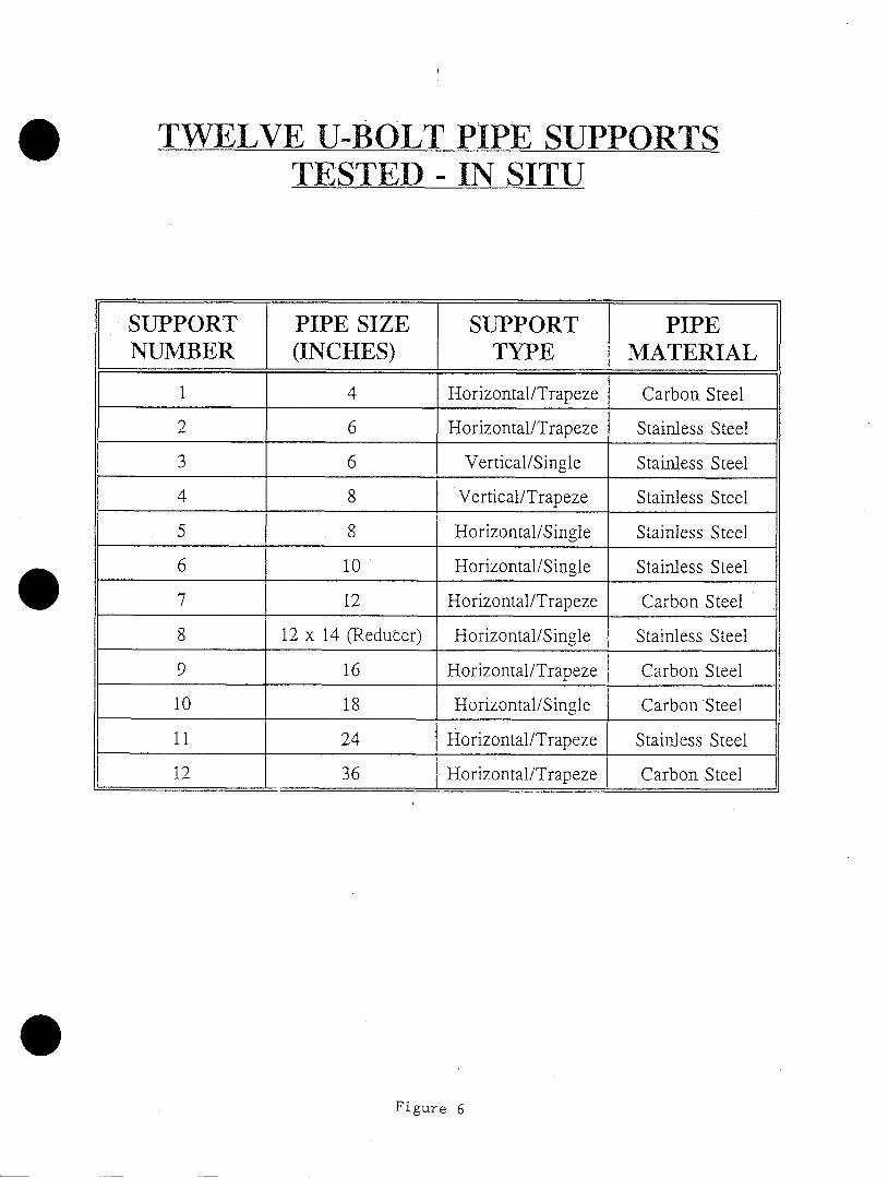
implementation assures support stability, 12 in situ tests wereperformed on various size piping. These tests were performed by
applying a maximum lateral test load (in a direction parallel to the
cross piece) corresponding to 1.44 times the calculated support
rotational design capacity. All results were positive in that norotation or slippage occurred. These tests include a wide variety ofsizes/types of U-Bolts including horizontal trapeze configurations whichwould be of most interest.
Discussions were held between TVA, the chairman of the WRC Bulletin 353,and the author of Section 2.4.5.3 as to the intent of the section. Asdescribed by the author of Section 2.4.5.3, the intent was not toprohibit or require removal of U-Bolts in these applications but to
provide guidelines which would include a torquing program to ensurestability when they are used.
El-5
APPLICABILITY OF U-BOLT TESTING
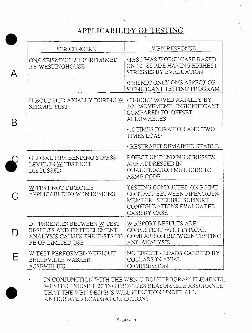
The following discussion regarding U-Bolt testing applicability iscross-referenced to the SER concerns as identified by same alphacharacters shown in Figure 4.
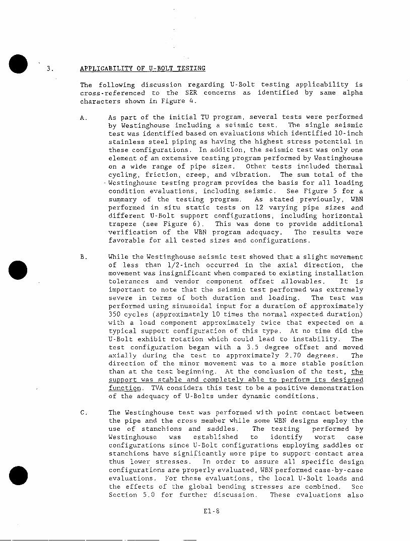
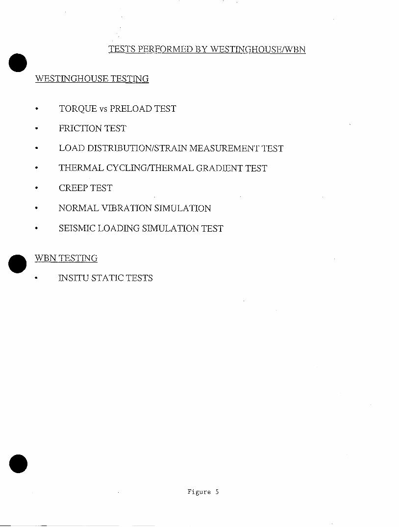
A. As part of the initial TU program, several tests were performedby Westinghouse including a seismic test. The single seismictest was identified based on evaluations which identified 10-inchstainless steel piping as having the highest stress potential inthese configurations. In addition, the seismic test was only oneelement of an extensive testing program performed by Westinghouseon a wide range of pipe sizes. Other tests included thermalcycling, friction, creep, and vibration. The sum total of theWestinghouse testing program provides the basis for all loadingcondition evaluations, including seismic. See Figure 5 for asummary of the testing program. As stated previously, WBNperformed in situ static tests on 12 varying pipe sizes anddifferent U-Bolt support configurations, including horizontaltrapeze (see Figure 6). This was done to provide additionalverification of the WBN program adequacy. The results werefavorable for all tested sizes and configurations.
B. While the Westinghouse seismic test showed that a slight movementof less than 1/2-inch occurred in the axial direction, themovement was insignificant when compared to existing installationtolerances and vendor component offset allowables. It isimportant to note that the seismic test performed was extremelysevere in terms of both duration and loading. The test wasperformed using sinusoidal input for a duration of approximately350 cycles (approximately 10 times the normal expected duration)with a load component approximately twice that expected on atypical support configuration of this type. At no time did theU-Bolt exhibit rotation which could lead to instability. Thetest configuration began with a 3.5 degree offset and movedaxially during the test to approximately 2.70 degrees. Thedirection of the minor movement was to a more stable positionthan at the test beginning. At the conclusion of the test, thesupport was stable and completely able to perform its designedfunction. TVA considers this test to be a positive demonstrationof the adequacy of U-Bolts under dynamic conditions.
C. The Westinghouse test was performed with point contact betweenthe pipe and the cross member while some WBN designs employ theuse of stanchions and saddles. The testing performed byWestinghouse was established to identify worst caseconfigurations since U-Bolt configurations employing saddles orstanchions have significantly more pipe to support contact areathus lower stresses. In order to assure all specific designconfigurations are properly evaluated, WBN performed case-by-caseevaluations. For these evaluations, the local U-Bolt loads andthe effects of the global bending stresses are combined. SeeSection 5.0 for further discussion. These evaluations also
E1-8
3 .
considered the use stiffness variances associated with the ofstanchions or saddles use as well as longer U-Bolts.
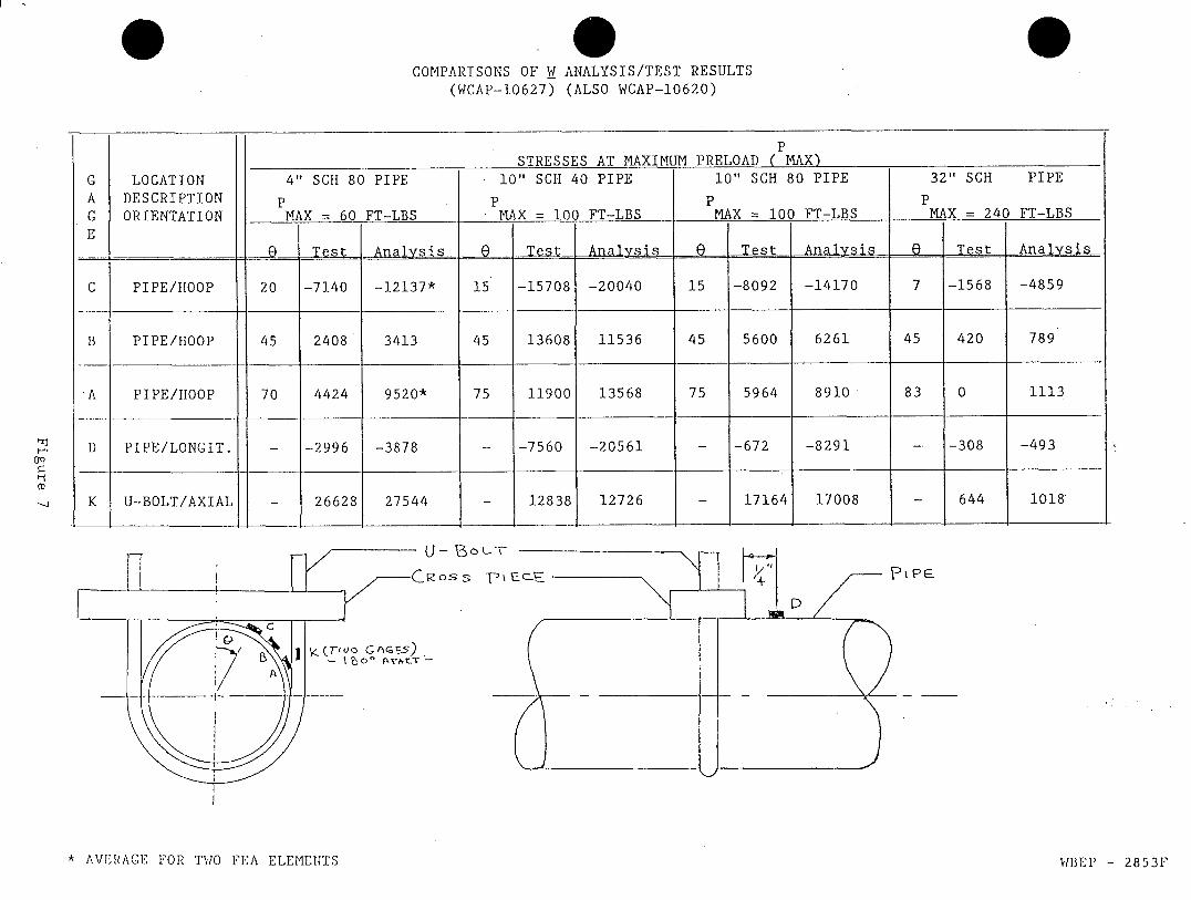
D. TVA reviewed the test and finite element analysis resultspreviously submitted in WCAP-10627 (see Figure 7) and found veryfavorable correlation between the test data and the finiteelement analysis results. Generally, the finite element resultsare conservative. The minor exceptions are attributed to thefit-up between the U-Bolt and the pipe since finite elementanalysis assumes a perfectly round pipe. Since in reality nopipe is perfectly round, small differences as shown in theWestinghouse test are expected and are not significant whendealing with ductile materials like piping. TVA considers thestress levels found by the testing to be within acceptableengineering limits as compared to the finite element analysis.TVA further adds to the design margin by the very conservativemethod of applying loads and stresses as described in Section 5.The close correlation of test and analysis results combined witha very conservative treatment of loads provides a reasonable andacceptable engineered design.
E. The Westinghouse test was performed without the use of Bellevillewashers that are being used with WBN installations. TVA hasevaluated this and determined there would be no adverse effectto the testing due to the Belleville washers. This is based onthe fact that the WBN U-Bolts remain in tension under all designloading conditions and the net change in stiffness between theU-Bolt assembly with or without Belleville washers isinsignificant. Any compressive load will be carried by theBelleville limit stop tubing collars. Even if small gaps occurafter this, the gaps would be of a size consistent with gapsallowed on other types of supports and therefore would have noeffect on the global overall piping analysis. See Figure 8.
TVA has concluded that the Westinghouse testing forms a viabletechnical basis when combined with WBN specific analyticalenhancements and in situ site testing.
El-9
APPLICABILITY OF TESTING
A
B
Figure 4
SER CONCERN WBN RESPONSE
ONE SEISMiC TEST PERFORMED -TEST WAS WORST CASE BASEDBY WESTINGHOUSE ON 10" SS PIPE HAVING HIGHEST
STRESSES BY EVALUATION
*SEISMIC ONLY ONE ASPECT OFSIGNIFICANT TESTING PROGRAM
U-BOLT SLED AXIALLY DURING W - U-BOLT MOVED AXIALLY BYSEISMIC TEST 1/2" MOVEMENT. INSIGNIFICANT
COMPARED TO OFFSETALLOWABLES
*10 TOMES DURATION AND TWOTIMES LOAD
* RESTRAINT REMAINED STABLE
GLOBAL PIPE BENDING STRESS EFFECT ON BENDING STRESSESLEVEL IN W TEST NOT ARE ADDRESSED INDISCUSSED QUALIFICATION METHODS TO
ASME CODE
WT TEST NOT DIRECTLY TESTING CONDUCTED ON POINTAPPLICABLE TO WBN DESIGNS CONTACT BETWEEN PIPECROSS-
MEMBER. SPECIFIC SUPPORTCONFIGURATIONS EVALUATEDCASE BY CASE
DIFFERENCES BETWEEN W TEST W REPORT RESULTS ARERESULTS AND FINITE ELEMENT CONSISTENT WIT TYPICALANALYSIS CAUSES THE TESTS TO COMPARISON BETWEEN TESTINGBE OF LIMITED USE AND ANALYSIS
W TEST PERFORMED WITHOUT NO EFFECT - LOADS CARRIED BYBELLEVILLE WASHER COLLARS INT AXLALASSEMBLIES COMPRESSION
IN CONJUNCTION WITH THE WBN U-BOLT PROGRAM ELEMENTS,WESTINGHOUSE TESTING PROVIDES REASONABLE ASSURANCETHAT THE WBN DESIGNS WILL FUNCTION UNDER ALLANTICIPATED LOADING CONDITIONS
C
D
E
TESTS PERFORMED BY WESTINGHOUSE/WBN
WESTINGHOUSE TESTING
* TORQUE vs PRELOAD TEST
* FRICTION TEST
* LOAD DISTRIBUTION/STRAIN MEASUREMENT TEST
* THERMAL CYCLING/THERMAL GRADIENT TEST
* CREEP TEST
e NORMAL VIBRATION SIMULATION
* SEISMIC LOADING SIMULATION TEST
WBN TESTING
* INSITU STATIC TESTS
Figure 5
TWELVE U-BOLT PIPE SUPPORTSTESTED - IN SITU
Figure 6
,SUPPORT PIPE SIZE SUPPORT PIPENUMBER (INCHES) TYPE MATERIAL
1 4 Horizontal/Trapeze Carbon Steel
2 6 Horizontal/Trapeze Stainless Steel
3 6 Vertical/Single Stainless Steel
4 8 Vertical/Trapeze Stainless Steel
5 8 Horizontal/Single Stainless Steel
6 10 Horizontal/Single Stainless Steel
7 12 Horizontal/Trapeze Carbon Steel
8 12 x 14 (Reducer) Horizontal/Single Stainless Steel
9 16 Horizontal/Trapeze Carbon Steel
10 18 Horizontal/Single Carbon'Steel
11 24 Horizontal/Trapeze Stainless Steel
12 36 Horizontal/Trapeze Carbon Steel
-
0COMPARISONS OF W ANALYSIS/TEST RESULTS
(WCAP-10627) (ALSO WCAP-10620)
Os s
* AVERAGE FOR TWO FEA ELEMEU4TS
PSTRESSES AT MAXIMUM PRELOAD ( MAX)
G LOCATION 4" SCH 80 PIPE 10" SCH 40 PIPE 10" SCH 80 PIPE 32" SCH PIPE
A DESCRIPTION P P P PG ORIENTATION MAX = 60 FT-LBS MAX = 100 FT-LBS MAX - 100 FT-LBS MAX = 240 FT-LBSE
- Q IeLAnanayii 0-A Test Analsis Test Analysis
C PIPE/IIOOP 20 -7140 -12137* 15 -15708 -20040 15 -8092 -14170 7 -1568 -4859
B PIPE/HOOP 45 2408 3413 45 13608 11536 45 5600 6261 45 420 789
A PIPE/HOOP 70 4424 9520* 75 11900 13568 75 5964 8910 83 0 1113
D PIPE/LONGIT. - -2996 -3878 - -7560 -20561 - -672 -8291 - -308 -493
K U-BOLT/AXIAL - 26628 27544 - 12838 12726 - 17164 17008 - 644 1018
PI P .
VIBEP l - 28531'

MODIFIED DESIGN OF U-BOLT ASSEMBLY
SEE DETAIL E
SS HARDENE)D WASHER
UMllT SOPTUDIIIG COLLAR
EXISTING PLATE
INSTALLED POSITIONPRIOR TO SPRINGC COMPRESSION
FINAL COMPRESSED POSITIONI
DETAIL BDETAIL A(SCALE 3/1 -1-0) (SCALE I=I)
TENNESSEE VALLEY AUTHORITYWATTS BAR NUCLEAR PLANT
Figure 8

4. PIPE AND PIPE SUPPORT DEFLECTION
The global piping mathematical model is assumed infinitely rigid at thesupport points. To assure this condition, the WBN supports are limitedto a global deflection to no greater than 1/8-inch in the direction ofloading in accordance with the WBN FSAR and Design Criteria. Globalsupport deflection is the delta at the pipe center line under theapplicable design loads (see Figure 9). WBN has individually evaluatedeach pipe support and pipe segment and meet the applicable deflectioncriteria.
The piping at each support does experience local pipe deformation aswould be expected with any piping support arrangement. Although notspecifically required by ASME Code, WBN did evaluate this localizeddeformation at each U-Bolt location.
Enclosure 2, Question 2 provides additional clarification concerningpipe and pipe support deflection.
El-14

LOCAL PIPE DEFLEC71ONASME CRITERIA
I ,-"| I 1 ---:. 7., 7 ,
I
G L03AL SU POPRT SYST~E A DEFL ECTION
FSAR REOCZREEa S
Figure 9
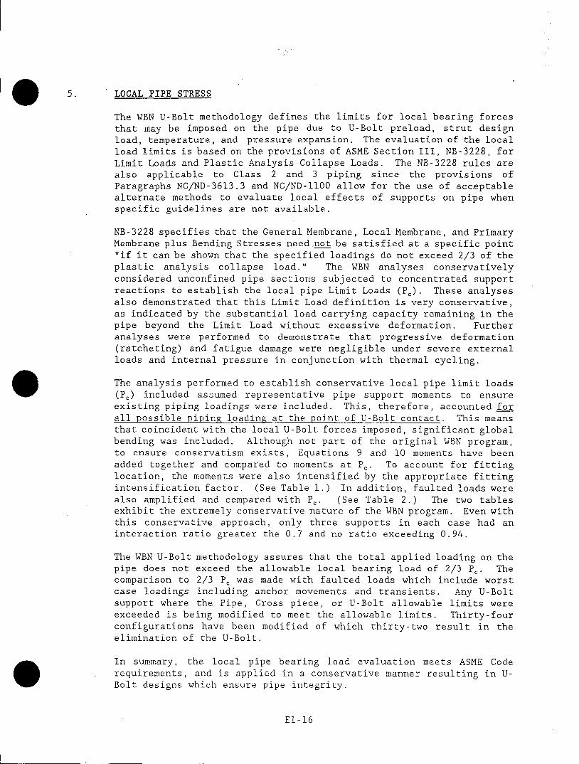
5. LOCAL PIPE STRESS
The WBN U-Bolt methodology defines the limits for local bearing forcesthat may be imposed on the pipe due to U-Bolt preload, strut designload, temperature, and pressure expansion. The evaluation of the localload limits is based on the provisions of ASME Section III, NB-3228, forLimit Loads and Plastic Analysis Collapse Loads. The NB-3228 rules arealso applicable to Class 2 and 3 piping since the provisions ofParagraphs NC/ND-3613.3 and NC/ND-llO0 allow for the use of acceptablealternate methods to evaluate local effects of supports on pipe whenspecific guidelines are not available.
NB-3228 specifies that the General Membrane, Local Membrane, and PrimaryMembrane plus Bending Stresses need not be satisfied at a specific point"if it can be shown that the specified loadings do not exceed 2/3 of theplastic analysis collapse load." The WBN analyses conservativelyconsidered unconfined pipe sections subjected to concentrated supportreactions to establish the local pipe Limit Loads (P.). These analysesalso demonstrated that this Limit Load definition is very conservative,as indicated by the substantial load carrying capacity remaining in thepipe beyond the Limit Load without excessive deformation. Furtheranalyses were performed to demonstrate that progressive deformation(ratcheting) and fatigue damage were negligible under severe externalloads and internal pressure in conjunction with thermal cycling.
The analysis performed to establish conservative local pipe limit loads(Pe) included assumed representative pipe support moments to ensureexisting piping loadings were included. This, therefore, accounted forall possible piping loading at the point of U-Bolt contact. This meansthat coincident with the local U-Bolt forces imposed, significant globalbending was included. Although not part of the original WBN program,to ensure conservatism exists, Equations 9 and 10 moments have beenadded together and compared to moments at P,. To account for fittinglocation, the moments were also intensified by the appropriate fittingintensification factor. (See Table 1.) In addition, faulted loads werealso amplified and compared with P, (See Table 2.) The two tablesexhibit the extremely conservative nature of the WBN program. Even withthis conservative approach, only three supports in each case had aninteraction ratio greater the 0.7 and no ratio exceeding 0.94.
The WBN U-Bolt methodology assures that the total applied loading on thepipe does not exceed the allowable local bearing load of 2/3 Pc. Thecomparison to 2/3 P. was made with faulted loads which include worstcase loadings including anchor movements and transients. Any U-Boltsupport where the Pipe, Cross piece, or U-Bolt allowable limits wereexceeded is being modified to meet the allowable limits. Thirty-fourconfigurations have been modified of which thirty-two result in theelimination of the U-Bolt.
In summary, the local pipe bearing load evaluation meets ASME Coderequirements, and is applied in a conservative manner resulting in U-Bolt designs which ensure pipe integrity.
El-16
CONCLUSION
The WBN program for U-Bolt supports used in conjunction with struts and snubbers
is comprised of an overall program consisting of testing, analysis, appropriate
acceptance criteria, and detailed installation procedures. The total WBN U-Bolt
population used in conjunction with struts and snubbers is 380 supports which is
approximately 3% of safety-related supports plant wide. Each support is
individually analyzed and those not meeting the acceptance criteria are being
modified. Thirty-four supports have been modified. The estimated cost to modify
the remaining population is approximately 5 million dollars.
The WBN program provides for properly engineered U-Bolt supports that ensure
piping integrity, support stability, and meet code and engineering requirements.
El-17
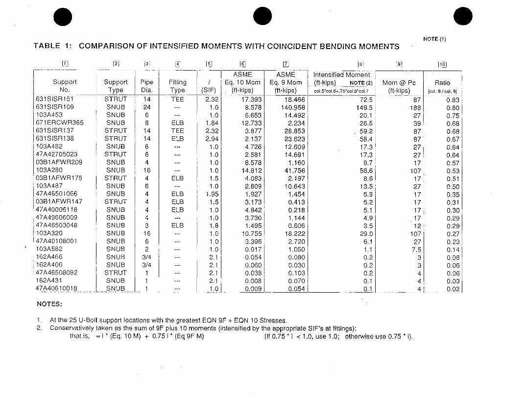
NOTE (1)TABLE 1: COMPARISON OF INTENSIFIED MOMENTS WITH COINCIDENT BENDING MOMENTS
111
SupportNo.
631 S1 SR 161631S ISR 109103A453671 ERCWR365
i 631SISR137| 631SISR138|103A48247A4270502303B1AFWR209103A280
|03B1 AFWR175103A487
147A4650106603B1AFWR147
*47A4000611847A49606009
k 47A46503048.103A320j'47A40108001103A582162A466
,162A40647A46508092
1162A431|47A40610018
Li @] T LS1
SupportType
STRUTSNUBSNUBSNUB
STRUTSTRUTSNUB
STRUTSNUBSNUB
STRUTSNUBSNUB
STRUTSNUBSNUBSNUBSNUBSNUBSNUBSNUBSNUB
STRUTSNUBSNUB
PipeDia.14246814146641646444431662
3/43/4
11
FittingTypeTEE
ELBTEEELB
ELB
ELBELBELB
ELBEL
ASVMEEq. 9 Mom
(ft-kips)i
(SI F)2.32
1.01.0
1.842.322.941.01.01.01.01.51.0
1.951.51.01.01.81.0j1.011 .02.1 I2.1 |2.112.11.0
K~ASVME
Eq. 10 Mom(ft-kips)
17.3938.5785.653
12.7333.8772.1374.7262.5818.578
14.8124.0832.8091.9273.1734.8423.7301.495
10.7553.3960.0170.0540.0600.0380.0080.009
Intensified Moment 7(ft-kieP) NOTE (2) tvcol.5'col.6+.75-co,.5.col.7
72.5149.5
20.126.559.258.417.317.3
9.756.6
8.613.55.95.25.14.93.5
29.06.11.10.20.20.2
0.1__i
NOTES:
1. At the 25 U-Bolt support locations with the greatest EON 9F + EON 10 Stresses.2. Conservatively taken as the sum of 9F plus 1 0 moments (intensified by the appropriate SIF's at fittings):
that is, = j t (Eq. 10 M) + 0.75 i * (Eq 9F M) (If 0.75 * i < 1.0, use 1.0; otherwise use 0.75 * i).
1 oj
loin @ Pc(ft-kips)
87188
27398787272717
1071727171717171 2
10727
7.533444
18.466140.958
14.4922.234
28.85323.62312.60914.6911.160
41.7562.197
10.6431.4540.4130.2181.1440.606
18.2222.7201.0500.0800.0300.1030.0700.054
Ratio[col. 8 / col. 9]
0.830.800.750.680.680.670.640.640.570.530.510.500.350.310.300.290.290.270.230.140.080.060.060.030.02

TABLE 2:
[1:I
SupportNo.
631 SISR1 38631 SISR1 61631 SISR1 3747A46501066
147A40610018|162A466103A482103A28003B1AFWR147631S ISR109103A487
1103A320103A58247A42705023
147A4650304847A40108001162A40647A4960600947A4000611803B1AFWR175162A431
|47A4650809203B1AFWR209103A453
1671 ERCWR365
COMPARISON OF AMPLIFIED FORCES VS. LIMIT LOAD
121
SupportType
STRUTSTRUTSTRUTSNUBSNUBSNUBSNUBSNUB
STRUTSNUBSNUBSNUBSNUB
STRUTSNUBSNUBSNUBSNUBSNUB
STRUTSNUB
STRUTSNUBSNUBSNUB
L5:1 167 [7]
PipeDia.
14141 4413/461 64
2461 62636
3/4444
1
468
FittingTypeELBTEETEEELB
ELB
ELB
ELBELB
ELB
(SIF)2.942.322.321.95
1.02.11.01.01.51.01.01.01.01.01.81.02.11.01.01.52.12.11.01.0
1.84
NOTE (2)
CriticalComp.
PPPppPxPppUUPUPPPPxUUUUUx
NOTE (3)
F p(kips)
14.7815.2915.533.883.724.67
17.4053.41
8.2818.5613.1553.01
3.1014.902.039.621.013.922.993.171.770.782.69
14.643.58
I7-A]NOTE (4)
Fp (amp)(kips)
22.8121.6220.004.523.724.71
17.4053.41
8.4618.5613.1553.01
3.1014.902.309.621.033.922.993.341.830.882.69
14.643.88
18 ,
P c(kips)
24.1524.1524.15
6.796.518.46
31.3296.4915.3034.3724.88
105.196.63
32.755.06
23.223.06
12.1710.0914.278.465.39
17.15102.5835.04
NOTE (1)
1. At the 25 U-Bolt support locations with the greatest EQN 9F + EQN 10 Stresses.2. P = Pipe; U = U-Bolt; X = Cross Piece3. Value of F p obtained from TVA Calculations TEACEBEMG72, Rev. 2, TEACEBEMG74, Rev.2 and TEACEBEMG75, Rev. 1.
4. Fp (amp) = 2 ( Ui + Ut + Up + 0.75 i * P/2 * { 1 - 1 / [ alpha * (Kp / Kci + 1 ) ]} )
i19
RatioFp(amp) / Pc
col.7A / col.8
0.940.900.830.660.570.560.560.550.550.540.530.500.470.450.450.410.340.320.300.230.220.160.160.140.11
NOTES:
ENCLOSURE 2
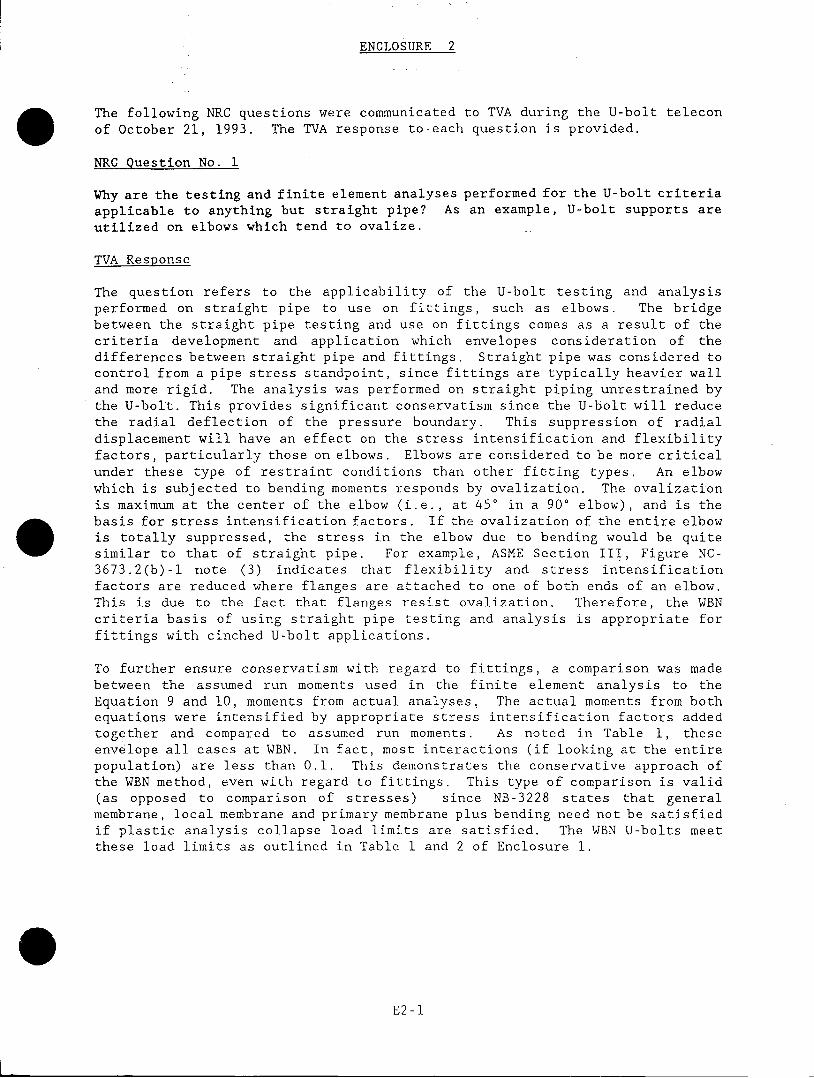
The following NRC questions were communicated to TVA during the U-bolt teleconof October 21, 1993. The TVA response to-each question is provided.
NRC Question No. 1
Why are the testing and finite element analyses performed for the U-bolt criteriaapplicable to anything but straight pipe? As an example, U-bolt supports areutilized on elbows which tend to ovalize.
TVA Response
The question refers to the applicability of the U-bolt testing and analysisperformed on straight pipe to use on fittings, such as elbows. The bridgebetween the straight pipe testing and use on fittings comes as a result of thecriteria development and application which envelopes consideration of thedifferences between straight pipe and fittings. Straight pipe was considered tocontrol from a pipe stress standpoint, since fittings are typically heavier walland more rigid. The analysis was performed on straight piping unrestrained bythe U-bolt. This provides significant conservatism since the U-bolt will reducethe radial deflection of the pressure boundary. This suppression of radialdisplacement will have an effect on the stress intensification and flexibilityfactors, particularly those on elbows. Elbows are considered to be more criticalunder these type of restraint conditions than other fitting types. An elbowwhich is subjected to bending moments responds by ovalization. The ovalizationis maximum at the center of the elbow (i.e., at 450 in a 900 elbow), and is the
basis for stress intensification factors. If the ovalization of the entire elbowis totally suppressed, the stress in the elbow due to bending would be quitesimilar to that of straight pipe. For example, ASME Section III, Figure NC-3673.2(b)-l note (3) indicates that flexibility and stress intensificationfactors are reduced where flanges are attached to one of both ends of an elbow.This is due to the fact that flanges resist ovalization. Therefore, the WBNcriteria basis of using straight pipe testing and analysis is appropriate forfittings with cinched U-bolt applications.
To further ensure conservatism with regard to fittings, a comparison was madebetween the assumed run moments used in the finite element analysis to theEquation 9 and 10, moments from actual analyses. The actual moments from bothequations were intensified by appropriate stress intensification factors addedtogether and compared to assumed run moments. As noted in Table 1, theseenvelope all cases at WBN. In fact, most interactions (if looking at the entirepopulation) are less than 0.1. This demonstrates the conservative approach ofthe WBN method, even with regard to fittings. This type of comparison is valid(as opposed to comparison of stresses) since NB-3228 states that generalmembrane, local membrane and primary membrane plus bending need not be satisfiedif plastic analysis collapse load limits are satisfied. The WBN U-bolts meetthese load limits as outlined in Table 1 and 2 of Enclosure 1.
E2-1
NRC Question No. 2
Explain how the Watts Bar deflection criteria is met considering the results ofthe U-bolt stiffness analyses. Watts Bar deflection criteria is specified as1/8" for total load and 1/16" for seismic applications or the minimum designload, whichever is greater.
TVA Response
In the SER it is stated that "the applicant's use of Belleville washers in theU-bolt pipe clamp design has resulted in a more flexible joint design undercompressive load conditions." Support for this claim cites a discussion in theWBN response to the IDI questions on the stiffness of the pipe U-bolt assemblywhere it is stated that "the effect of the Belleville washers is to cause theassembly to have a lower bound stiffness value."
The discussion in the WBN response to the IDI questions focuses upon the U-boltonly - not pipe U-bolt assembly. In the early portion of the discussion, itclearly states that "The U-bolt stiffness, as supplemented by the Bellevillewashers, affect the calculations of minimum required preload as well as thecalculation of temperature and pressure effects." The later portion of thediscussion applies to the clamping mechanism during the preloading process andwas used to support the conclusion that "for the calculations of temperature andpressure effects on the U-bolt tension, the U-bolt stiffness will be taken as onehalf of the upper bound value." There are other parts of the "pipe U-boltassembly" that are discussed similarly. In addition, the discussion not onlycovered the U-bolt lower bound that was cited in the SER, but also addressed theU-bolt upper bound situation prior to drawing the conclusion for appropriatevalue of stiffness for the U-bolt only when calculating the required preload forstability. The stiffness of each part of the pipe U-bolt assembly is addressedwhen establishing the initial preload and designing the Belleville washers.
After the washer assemblies with machined collars are installed in accordancewith the WBN controlled installation procedure, the Belleville washer stiffnesshas negligible effect on the overall stiffness of the pipe U-bolt assembly underseismic compressive loads. The seismic compressive strut load is applied to thesupport crosspiece and transferred directly to the pipe. The Belleville washeris not in this load path and therefore, cannot influence the overall stiffness.Because the overall support stiffness is not altered by the Belleville washers,the support deflection under seismic loads is also not affected by the Bellevillewashers.
Since (1) support deflection is checked during the overall support design processto assure compliance with the support deflection limits specified in the FSAR andDesign Criteria as discussed in Enclosure 1, Section 4, (2) the lower boundstiffness only affects the preload determination and (3) U-bolt stiffness(including Belleville washers) under seismic compressive strut load hasnegligible affect an overall support stiffness, compliance with the supportdeflection limits is maintained.
E2-2

ENCLOSURE 3
Following are representative calculations and photographs of the installationsrequested by the staff.
Support # Controlling Element
47A427-05-023
63-lSIS-R161
70-lCC-R731
U-Bolt
Pipe
Crosspiece
E3-1

APPENDIX 2 OF TEACEBEMG75PAGE 2-61 OF 2-461
RobertL. Cloud andAsso ates Inc
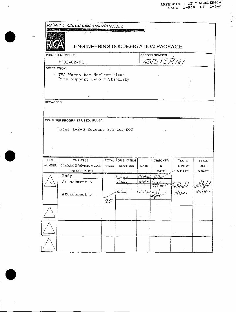
ENGINEERING DOCUMENTATION PACKAGE
PROJECT NUMBER: RECORD NUMBER:
P203-02-01 473'-I270 523DESCRIPTION:
TVA Watts Bar Nuclear PlantPipe Support U-Bolt Stability
KEYWORDS:
COMPUTER PROGRAMS USED. IF ANY:
Lotus 1-2-3 Release 2.3 for DOS
REV- CHANGES TOTAL ORIGINATING CHECKER TECH- PROJ.
NUMBER INCLUDE REVISION LOG. PAGES ENGINEER DATE & REVIEW MGR.
. IF NECESSARY) __DATE & DATE & DATE
.Body It y o
0 Attachment A A k H
AA
Attachment B

APPENDIX 2 OF TEACEBEMG75PAGE 2-62 OF 2-461
ROBERT L. CLOUD AsSOCJATES, INC.
BY. LIDATh-+' SupportNo. q727LM I|2 PAGENO I oF2=__ D__ 1WBN U-Bolt Evaluation= PROJ. NO. P203-020
1.0 Purpose
The calculation defines the initial U-bolt preload needed to maintainstability of the support component against overturning effects due toeccentric loading and seismic self-weight excitation.
2.0 Scope
The calculation verifies the adequacy of the specified initial preloadnecessary to assure support component stability. The calculationverifies support components for forces associated with the -specifiedpreload.
3.0 Methodoloqy and Criteria
The methodology and criteria for the -definition and verification ofpreload requirements is that specified by RICA Report No. RLCA/P203/02-01-92/001 (Reference 1).
4.0 Assumptions and Approximations
a. Support weight (W,) subject to self-weight excitation effects is usedas defined in the pipe stress analysis calculation. If the pipe stresscalculation -does not specify a support weight value, support weight isestimated from support sketch inforimtion.
b. The support weight (W,) center of gravity is considered to be locateda distance e, from the pipe center line as follows:
If the end bracket is attached on the opposite side of the crosspiece from the pipe, the center of gravity is assumed to be locatedat the same distance from the pipe as the end bracket pit location.
If the end bracket is attached to the same side of the cross pieceas the pipe, the center of gravity is assumed to be located on thecenter line of the cross piece.
c. Temperature of uninsulated support components is assumed to linearlydecay at 100 degrees F per inch from the pipe surface.
d. The maximum strut/snubber swing angle is assumed to be 5 degrees fromthe axis of the U-bolt. (The swing angle is only relevant to singlestrut/snubber stability.)
Assurmtions requiring confirmation (if any) are summarized in Attachment D.

APPENDIX 2 OF TEACEBEMG75
PAGE 2-63 OF 2-461ROBERT L. CLOUb ASSOCIATES, INC.
S UptNo. 4+7A92.6 2 3 | PAGE 2 OFCXZD DAT } 4 WBN U-Bolt Evaluation |PRO. No. P>203-02-01
5.0 Results
Each leg of the U-bolt(s) should be tensioned to an initial preloadbetween the minimum and maximum initial preload specified on Sheet A-3of Attachment A.
References:
1. RLCA Report prepared for the Tennessee Valley Authority,"Methodology and Design Criteria for Pipe Supports Utilizing U-Bolts to Maintain Stability", Report No. RLCA/P203/02-01-9 2 /0 0 1 ,Revision 0, September If,, 1992.
2. Pipe Support Sketch reproduced in Attachment C.3. Other references, as identified in Attachments A and B.
O Attachments:
A. Initial Preload Computation 4 SheetsLotus Version 2.3 Spreadsheet
B. Input Worksheets 6 Sheets
C. Support Sketch -Sheets
D. Confirmation Punch List /Y-ak' Sheet

Robert L. Cloud and Associates. Inc.TVA Watts Bar Nuclear Plant
Single Strut/Snubber Support No.47A427-05-023
Proposed Modification of Cross Piece
By: Date: JJJ4 Cale.
Chk'd: 8U Date: Proj.
APPENDIX 2 OF TEACEBEMG75PAGE 2-64 OF 2-461
Attachment ANo.: 47A427-05-023No.: P203-02-01
[Ref.]
Pipe Stress Analyis Calc. NoJRev.:
Pipe Outside DiamneterWall ThicknessMaterialDesign PresssureDesign TemperatureE-ModulusYield Strength
U-Bolt(s) Rod DiameterLeg CL to CLNet Stress Area (one leg)No. of U-BoltsShim Plate ThicknessStanchion HeightStanchion WidthMean Stanchion Temp.U-bolt MaterialDesign TemperatureE-ModulusYield StrengthMean U-Bolt Leg Temp.
0600200-05-01 /13
DT
PoToE(p)Sy(p)
dOK dimenAtntHBc
Ts
TuE(u)Sy(u)Tu,leg
Cross Piece Section: 'PL",COMPACT,"OTHER'and HeightEnd Bracket Width
hW
Bracket Length 'B dirnenHalf length of End Bracket L2Remaining Half Length LiMom of Inertia, cross piece 11Mom of Inertia @ bracket 12Sec. Area, cross piece AlSec. Area @ bracket A2Cross Piece MaterialDesign Temperture TcE-Modulus E(x)Yield Strength Sy(c)Shear Area Coef. f
Self-Wt Support Wt, EffectiveExcitation Acceleration, Parallel
Acceleration, PerpendicularEccentricity, On AxisEccentricity, Offset
Strut Load Max. Design LoadEccentricityAngle
Coefficient ofThermalExpansion
PipeU-Bolt (Bend Section)U-bolt (Mean Leg)StanchionX-Piece
Wcpala2elo2
PATheta
600600400600600
Node No.: 76
Input Data 6.625 in0.432 in
SA-333 Gr.6 61185 psi -
600 dog :;25,700,000 psi
25,900 psi
0.63 In7.38 in
0.226 in2
2 -
0.00 In0.00 In0.00 in600 deg F
ASTM A36 -600 dog F
25,700,000 psi26,600 psi
400 dog F
0.00 In0.00 in3.69 In
ASTM A36600 dog F
25,700,000 psi26,600 psi
1.63 g2.54 g
~~~~...,''.'.,.,,'.'.0.00 in
8186 lbsen,.................... ............... ...............
2.0 deg
7.23E-06 in/in/dog F7.23E-06 in/in/deg F6.82E-06 inrin/deg F7.23E-06 in/in/dog F7.23E-06 in/in/dog F
Ref 3
Ref 8, Par 3.6b
Ref 5.cRef 5.cRef 5.cRef S.cRef 5.c
Page A-1 of 4
Ref 3Ref 3Ref 3Ref 3Ref 3Ref 3Ref 6.a
Ref GaRef 6aUNC SeriesRef 4Ref 4Ref 4Ref 4
Ref 6a@ PipeRef 5.dRef S.e
g~e1 4-.-
Ref 6(B/2)(K/2-L2)
@ end bd edgeRef 5.dRef 5.e
1,1ag 39
09-Nov-92WBN-US5
Robert L. Cloud and Associates, Inc.TVA Watts Bar Nuclear Plant
Single Strut/Snubber Support No.47A427-05-023
Proposed Modification of Cross Piece
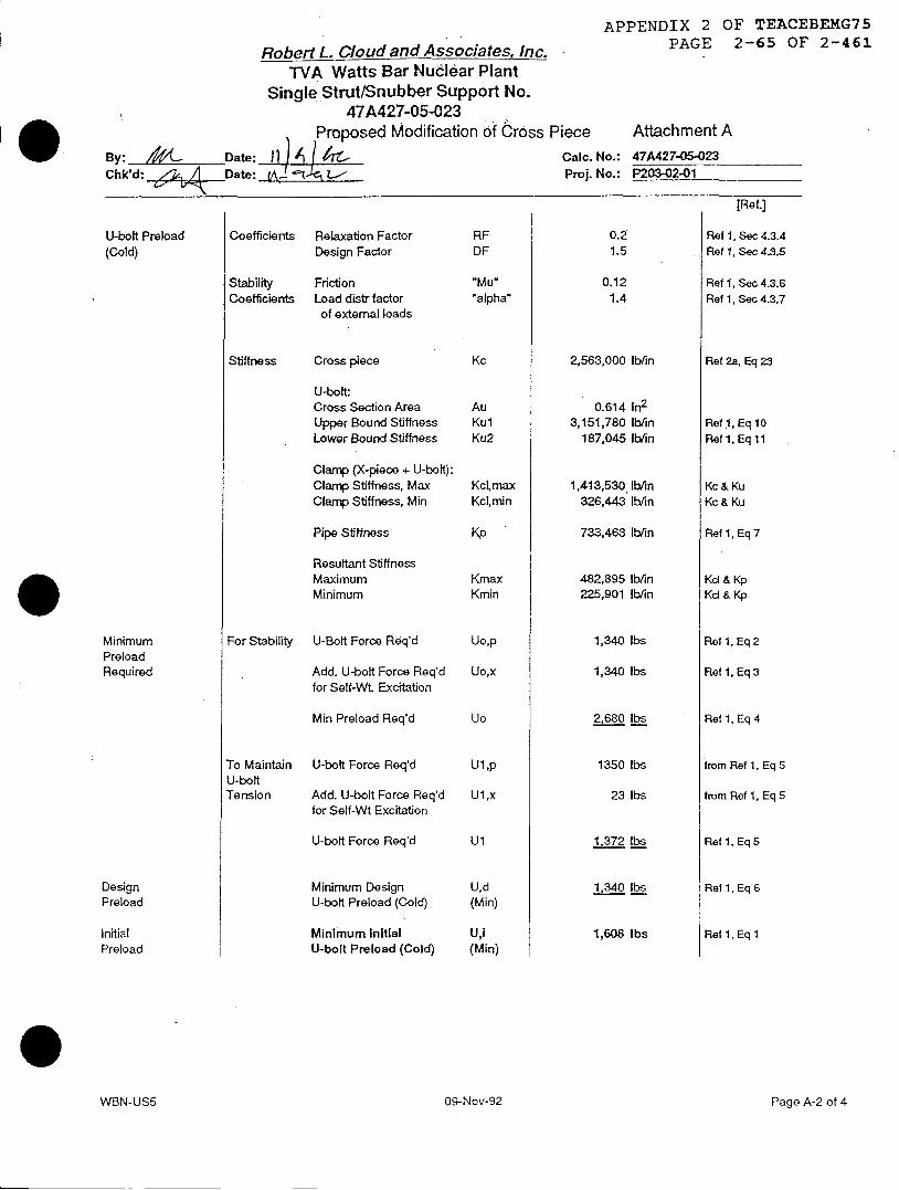
APPENDIX 2 OF TEACEBEMG75PAGE 2-65 OF 2-461
Attachment A
CaIc. No.: 47A427-05-023Proj. No.: P203-02-01
By: 1 4 Date: 11 A IChk'd: / Date: a. I L; V
U-bolt Preload(Cold)
To MaintainU-boltTension
U-bolt Force Req'd
Add. U-bolt Force Req'dfor Self-Wt Excitation
U-bolt Force Req'd
Minimum DesignU-bolt Preload (Cold)
Minimum InitialU-bolt Preload (Cold)
Coefficients Relaxation FactorDesign Factor
Stability FrictionCoefficients Load distr factor
of external loads
Stiffness Cross piece
U-bolt:Cross Section AreaUpper Bound StiffnessLower Bound Stiffness
Clamp (X-piece + U-bolt):Clamp Stiffness, MaxClamp Stiffness, Min
Pipe Stiffness
Resultant StiffnessMaximumMinimum
For Stability U-Bolt Force Req'd
Add. U-bolt Force Req'dfor Self-Wt Excitation
Min Preload Req'd
RFDF
.Mu."alpha'
Kc
AuKulKu2
Kcl,maxKcl,min
Kp
KmaxKmin
Uo,p
Uo,x
Uo
U1,p
U1,x
Ul
U,d(Min)
U,i(Min)
0.21.5
0.121.4
2,563,000 lb/in
0.614 in2
3,151,780 lb/in187,045 lb/in
1,413,530 lb/in326,443 Ib/in
733,463 lb/in
482,895 Ib/in225,901 Iblin
1,340 lbs
1,340 lbs
2.680 Ibs
1350 lbs
23 lbs
1 340 lbs
1,608 Ibs
Page A-2 of 4
[Ref.]
Ref 1, Sec 4.3.4Ref 1, Sec 4.3.5
Ref 1, Sec 4.3.6Ref 1, Sec 4.3.7
Ref 2a, Eq 23
Reft1, Eq 10Ref 1, Eq 11
Kc & KuKc & Ku
Ref 1, Eq 7
Kd & KpKd & Kp
Ref 1, Eq 2
Ref 1, Eq 3
Ref 1, Eq 4
from Ref 1, Eq 5
from Ref 1, Eq 5
Ref 1, Eq 5
Ref 1, Eq 6
Ref 1, Eq 1
MinimumPreloadRequired
DesignPreload
InitialPreload
WVBN-US5 09-Nov-92

Robert L. Cloud and Associates, Inc.TVA Watts Bar Nuclear Plant
Single Strut/Snubber Support No.47A427-05-023
Proposed Modification of Cross PieceBy: ,, Date: V * -^ /'lPrCalc.Chk'd: <xu Date: VVI- Rtv- Proj.
APPENDIX 2 OF TEACEBEMG75PAGE 2-66 OF 2-461
Attachment ANo.: 47A427-0S-023No.: P203-02-01
Min U-bolt Loadat DesignPressure & Temp.
Pipe Acceptance(for Min Preloadat Po, To)
SupportComponentStresses(for Min Preloadat Po, To)
MaximumU-boltPreload
AdditionalU-BoltTension
PipeLoad
Pressure EffectsTemperature EffectsStrut Tension EffectTotal U-bolt force, one side
Max Force on PipeAllowable Load% Max Force of AllowablePreload Umit for Pipe
Cross Piece Bending, PrimaryStress Nomnal AISC Allowable
% of Allowable, Primary
Bending, MaximumMaximum Allowable% of Allowable, Maximun
Preload Umit for X-piece
U-Bolt Tension, PrimaryTension Limit, Primary
% of Allowable, Primary
U-bolt Leg Tension, MaxLimit, Maximun% of Allowable, Max
Preload Limit for U-bolt
Maximum AllowableU-bolt PreloadPer U-boft Leg (Cold)
UpUtUsU
Fp2/X3Pc
fb,norrmalFb
fb,max.9 'sy
ft~nomnalFt
Ft~max
U,l(max)
418 lbs1,647 lbs1,925 lbs7,206 lb
14,898 lbs21,831 lbs68.20% <1 req'd3 341 Lbs/1e<~
11,372 psi20000 psi56.9% <1 req'd
15,939 psi23,940 psi66.6% <1 req'd
3417 lbM
5,141 lbs7,214 lbs71.3% <1 req'd
7,206 lbs10,821 lbs66.6% <1 req'd
2 645 tls>eg
2,645 lbs
INSTALLATION COLD GAP g 0.0000 In
INmAL PRELOAD MINIMUM PRELOAD (COLD) PER LEG Ul (min) 1,700 lbsREQUIREMENTS
MAXIMUM PRELOAD (COLD) PER LEG Uj (max) 2,600 lbs
[Ref.]
Ref 1, Eq 16Ref 1, Eq 14, 15from Ref 1, Eq 17Ul+UpU+Us
Ref 1, Eq 18Ref 1, Eq 19, 20
(S=1.667 inA3)Ref 1, Sec 5.4
(S=1.667 inA3)Ref 1, Sec 5.4
Ref 1, Sec 5.3
Ref 1, Sec 5.3
U-BoltControls
Page A-3 of 4WBN-US5 09-Nov-92
0

Robert L. Cloud and Associates, Inc.TVA Watts Bar Nuclear Plant
Single Strut/Snubber Support No.47A427-05-023
Proposed Modification of Cross Piece
By: - -Date: l} iJ Ai |Z Calc.
Chk'd: D ate: Lei,• Proj.
APPENDIX 2 OF TEACEBEMG75PAGE 2-67 OF 2-461
Attachment ANo.: 47A427-05-023No.: P203-02-01
REFERENCES:
1.0 RLCA Report No. RLCAfP203/02-01-921001, Rev. 0., 9-17-92,"Methodology and Design Critiera for Pipe Supports Utilizing U-bolts..."
2.0 a RLCA Report No. P142/01-86/004, Umited Release 1, 8-27-92,-CINCHED, SINGLE-STRUT U-BOLT SUPPORTS,Design Review, Application Procedure and Acceptance Critiera".
2.0 b. RLCA, Calculation No. P-142-1-514.007, Revision 1, 84-87.
3.0 Pipe Stress Analysis CalculationNoJRev. 0600200-05-01 /13
Supt Node No. 76
4.0 Support SketchNo. 47A427-05-023
Revision (See Attachment C)
5.0 ASME B&PVC Section III, Code of Record Edition/Addendaa Table 1-2.1 Sy for Ferritic Steels (1971 Ed + Addenda & Errata)b. Table 1-2.2 Sy for Austinetic Steels, etcc. Table 1-5.0 Coef. of Thermal Expansion (1971 Ed + Addenda & Errata)d. Table 1-6.0 Moduli of Elasticity (1971 Ed + Addenda & Errata)e. Table 1-13.1 Sy for Linear Type Component Supports
6.0 Bergen-Paterson Catalog No. 80a U-bolt: 6502 (Carbon Steol assumed to be ASTM A-36)b. End Bracket: 1000-7c. Other Parts
7.0 Not Used
8.0 TVA, WBN Design Critiera No. WB-DC-40-31.9, Revision 15."Criteria for Design of Piping Supports..."
9.0 AISC, "Specification for the Design...of Structural Steel for Buildings",7th Edition, Feburary 1969, w/ Supplements 1, 2, and 3.
Page A-4 of 4
[Ref.]
09-Nov-92WBN-US5
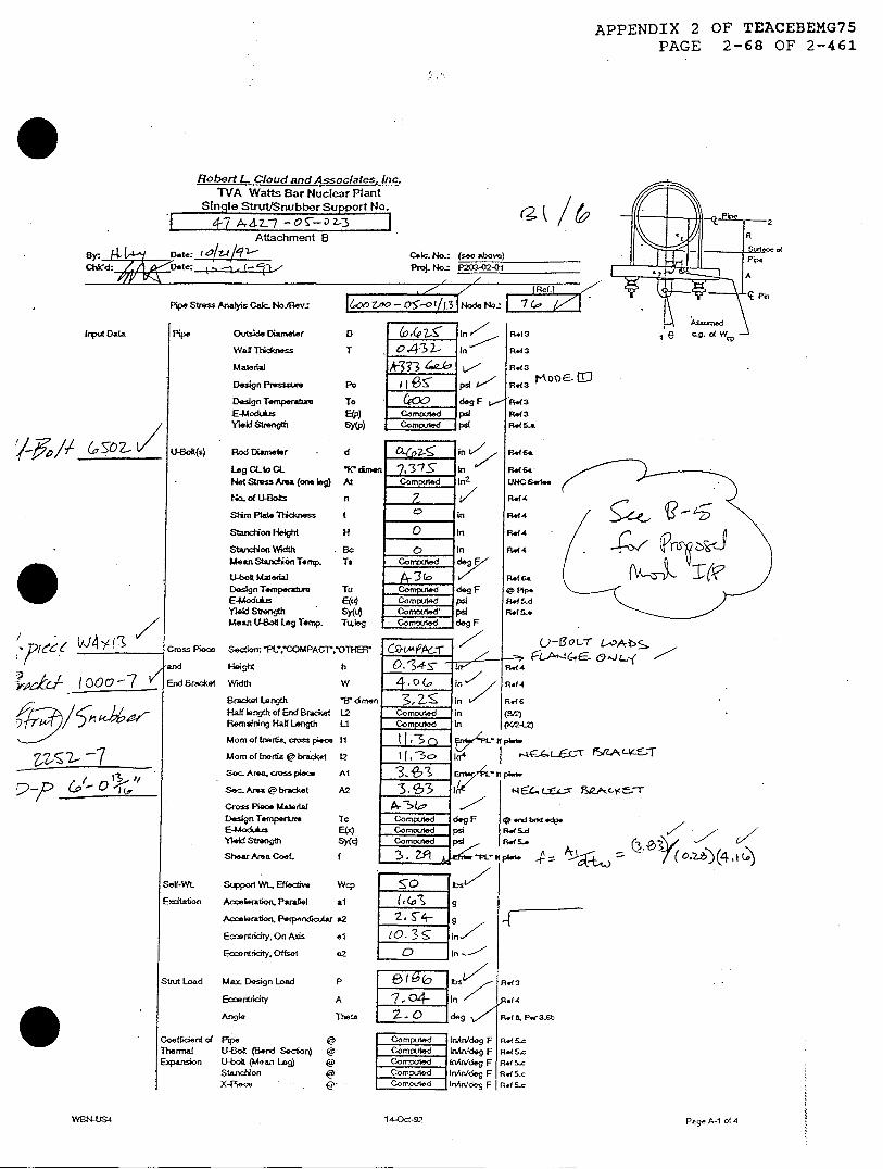
APPENDIX 2 OF TEACEBEMG75PAGE 2-68 OF 2-461
Robert L Cloud and Assoclates. Inc.TVA Watts Bar Nuclear Plant
Sinqle Strut/Snubber Support No.
41 47A4-7 &i- 223Attachment B
6F: _Jw/ Date: 10I/7 /q -Ctc'd: 5 te: I = c L4 ,
Pipe Stress Analyis Cab. t4oNRev:
pipe Outsade Diameter
Wall Tlgckness
Material
Design Pressvire
Design Tempeat-
E-Mod&usYield Strength
U-Boft(s) Rod Diameter
Leg CLto CLNet Stress Area (one eg)
No. of .-4oks
SHim Pate Thicness
Stxretion Height
Stuxdion WidthMean Stancion Temp.
U-bok Malredal
Design TemperatureEModLsYield StrengthMean U-olt Lg Temp.
Cross Piece
and
End Bracket
Cak. No.: (sea above)
Prcl No.: `23-f02-1
160 Z- o- t 3 Nod.t4.F7
D Ii)07-G In ' Rdt3
T [0o4-3 Z n R.d3
1kIS7• L' Rat3
To - 2)0 deg F R.(3E@p) Commilod pi Ht3SAtP) CanipbdI pd R S.A
d i &rC'c L,,/ - -
At
H
BcTs
Tu
EM4SuleTwes
Sedioc ,^OPL: MPACT`.OTHE3r
Height hWidth w
Bracket Length
Hatf length of End BradcetRemaining Hall Length
Mom of Ikmrtie, crss pieoe
Mom of Inertia @ bracet
Se. A-a. s pwce
Sec. Ara @ bracket
Cmss PFbce Malertal
Design TemperE4Aodu
iYwid Stength
Shear Area Coel.
Setf-WI Suppol Wl. Bfedie
Exilaton Aeleration, Parae
Acceeration, P*"pendlcLar
Eccerntiity, On Axis
Eaentriaty. Offset
Stt Load M.ax Design Load
Eccentricity
Coeffidcent ofThernalENpansion
Angie
PipeUBol (Bend Soc6iort-b (Mean Lag)StanofionX-4Ie -
BW dmenL2Li
11
t2
Al
A2
TcE(4
SY(C)
Wcp
al
r2
el
e2
p
A
Theta
14-0d-92
Irnpt Data
./-pp // (IOZl
& ioo-7 v
2:)p p6- o 't"
z 7,1
(2, / &
Page A-1 of 4

APPENDIX 2 OF TEACEBEMG75PAGE 2-69 OF 2-461
ROBERT L. CLOUT & ASSOCATES, C.
BBY D4 4 ATE CaIculation No. 4-7 A A427 -OSS:--| PAGE NO. OF__- 3M) DAT VV|N U-Bolt Evaluation PROJ. NO. P23-0201
Attachment B - Input Worksheets
2. Simplified Method - Design Input
2.1 Design Load >' I(
2.2 Lumped Mass C-V
- Table 4.2.4-1 of Ref.
fCalculated - see following pages
23 Center of Gravity A~4.. -74, -= 4-t, / =-03-
Single Strut/Snubber (Assumed symmetric) (See Figure 1)e (R+A) = /o.) -ia 7.o35+
0.0 Ia-
Trapeze: Struts/Snubbers same side as U-Bolt (See Figure 2)e = _(R + A) =i.e2 = 0.0 in for symmetric
= 1O05Q - T| for unsymmetric
[Re, _3[Ref
- Trapeze: Struts/Snubbers opposite side of U-Bolte, = (R +A) = - -__i
e4 = 0.0 in forsymmetric= JO.5Q - Tl for unsymmetnic
iEL
(See Figure 3)
- Calculated - see following pages
Figure 2: Trap-ze - Samne SideConfiguradon Configuration

APPENDIX 2 OF TEACEBEMG75PAGE 2-70 OF 2-461
ROBERT L. CLOUD & ASSOCIATES, INC.
BY /+ DATE ti/6 Calculation No. 47 242-7?S- 23IiWA6. 4 WVVBN U-Bolt Evaluation
Attachment B - Input Worksheets
2.4 Accelerations
Case I - Horizontal Pipe & Vertical Support (See ligure 4)a, = 20 g a, = 5.7 g
Case H - Horizontal Pipe & Horizontal Support (See Figme 5)a, = 1.0 g a2 = 6.7 g
Case HI - Vertical Pipe & Horizoutal Support (See Figure 6)a1 = 1.0g a2 = 6.7g
/Otiier
PAGE NO. e23 OF 6PROJ. NO. - 3P202-0
Figure 4: Case I Figure 5: Case II Figure 6: Case ]I
25 Swing Angle - Single Strut/Snubber OnlyInitial Cold Offset = . ) degreesInstallation Tolerance = I, 0 Pg-aCalculated Movement Swing = CXS degrees (See below)
Total Swing = (3 degrees Use Z .0 degrees
Calculated Movement Swing: 4
MaximumMovement inaUanrs Dinon, MM = 0;33 in ( Z#~3 V- 1Pin-Pin Dimension (Use Cold) = A 72- in_
Calculated Swing Angle, 0 = tan-' [MkPinPinj = . 3 degrees -
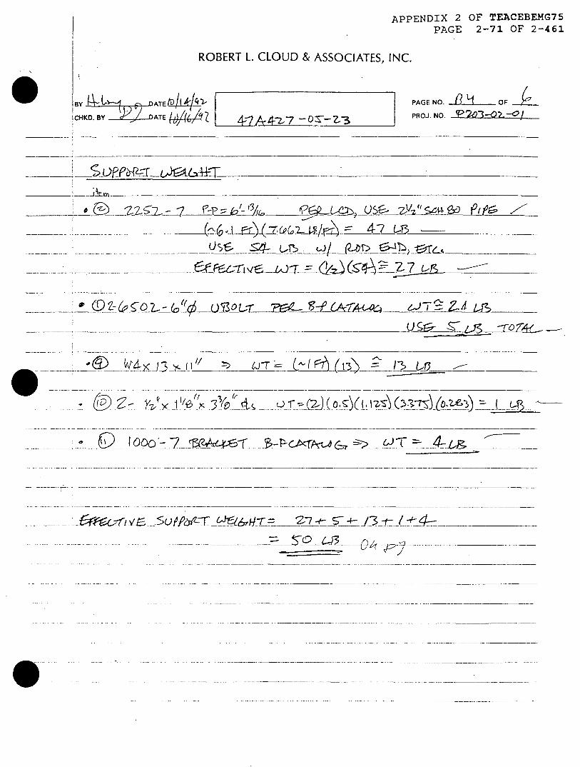
APPENDIX 2 OF TEACEBEMG75PAGE 2-71 OF 2-461
ROBERT L. CLOUD & ASSOCIATES, INC.
/
F BY DAATE | PAGE NO. I L OF I O
iCHKD. BY WeLDATE {4J/4/S I PROJ NO _______i/
-- - F61Sc> 1O4-_Z7u ____-o (--use)- @XJ9 4 -
- - - T56 A53 e 1- b; 6 --
- - .-CO 2Q-6b go- -- X- O7 A
- . - -.- -urn 3~4 s
e jSIII) lOOo -§- ~ -- r ~~ -t ___
..... -. -.-. ---- .--- ..........................................................................................................
-0 - ...-.. . -------
�4�c-f� v� 5ufl�-F �16�itLLE__Z7 �J3-t- / _________
__ -�O643 ___ _

Input Data
WBN-US4
APPENDIX 2 OF TEACEBEMG75PAGE 2-72 OF 2-461
Robert L Cloud and Assoclates. Inc.TVA Watts Bar Nuclear Plant
Single Strut/Snubber Support No.
L 4A42 4 -7 -- P/g5 - -a <- 2
Attachment B-Dte: 11_7 [l cI It4o.: (aee above) - ec
-e /~ ( 1 No P203 02 P-01
Pip SteSs Analys c6- Nov: I I N ode I- pi.,\
POp Outside Dameter D in R.f3 1 E C.g. OWc
Wal Thicikess T in Rd13
Materia- Rdt3
Design Pressur Po PSi Ref3
Design Te-mperature To degSF Rdx
E-Modis E(p) Comed si R*13YieldStuength SAp) Cam psi R"SA ie 4 / / |
UBdt(s) Rod Dlsmeter d In Ref "6
LegOLtoCL tdimen In P.&( GA
Net Stress Area (one bg) At Cormned in2
UNCSsia
No. of U-Boks n Rd14
Shim Ptae Tlickness t In Ret4
Stanchion Height H in Rof 4
Standiion Width Bc In R44 4
MeanStanhionTernp. Ts Comped degF
(.1oftMatedi Ratl -
DesignTemperature Tu -o degF RPi \JaE-Modukis E(u) Compu psi Raf54
Yield Stfength Sy(u) Computed I psI RP(SAMean U-Boft Leg Temp. Tu,leg Comduted deg F
Cross Piece Sedcti PACTOT -TH2R1 U /!and Height 4 ° in Rdf4 \ 2
End 8racket Width w 1i0 0 in/ Rdf4 4
Bradet Length dm in
Hae ength of End Bradcet Commyted in (Bt=Remaining Ha Length Li Camoutec in (Kr2-2) / /
Mom of Inertas cross I 0:, cc?7: 7i-p P 2 A2<{
MomofInertia@braket 12 =T ln4 j /9 l ) -3
Sec. Area, aoss piece r 1- tpl i.
Sec. Area @ bracket A2 In2
Cross Piece Malrw al
Design Tenperture Tc Comiuted deg F @ Ied btil ac.
E-Moduius E(x) Com d psi Re SdYield Strength Sy(Cq Comeed psi RFlo.
Shear Area Coef. f L. I Enl -PL- if pkrb.
Seaf-WL Support WM Etedive bv (
Excitation Accelenafion. Parauiel al g KAcceleration, Perpendlauar a2
Eccentricity. On Axis
Eccentridty. Offset e2 In
Strut Load Max. Design Load P R 3bs Ret3
Ecoentncity CA 3j ,3J I:/ Raf4
Angle Theta deg Ret B. Psr a6b
Coetficient of Pipe @Commned InAn/deg F Re s.Thermal U-Boft (Bend Section) @ L oIed inAn/deg F R.1&cExpansion U-bolt (Mean Leg) @ mpoZed InAn/deg F Rf. c
Stanchon f Gornued in&/deg F Re5.c
X-Piece P Comcrtedl Inhlndeo F R( S.c
14-0cl-92

APPENDIX 2 OF TEACEBEMG75PAGE 2-73 OF 2-461
ROBERKI L. CLUUD & AS5UCIAI ES, INC.
I BY - 4 /D ATE A4< PAGE NO. 2 JM OF 6
lCHKD. BY eSOATE i\V 6 -4RA4-- s< PROJ. NO. -i'-
6 *t!e__ -
-- -----
LA22 1a-
_vd,
*<44; -L412 0___-
X ,I .61 .. . .
1\ : (V\1 - ____ -- ___ / - 0- -- -
I= ----- ' "-
Pr --,
- - -
I
t - -\ -s . % r t -

APPENDIX 2 OF TEACEBEMG75PAGE 2-74 OF 2-461
jDCN a40. f7- /JdV--A* PAGE 6 OF /O
.. AKPA -E-
bASE DW J14. 0P-@'62'- A- PAGE -7
*- ("•4 PItE W Lc. L U-
PVZ -7T Rl STR P-p=,<- 0':/TS (ox Yz- " X L" A5 PP-5.TS 4A 4 A Yzt x. tc5 A5 RCC: D. C -U
F--I" A lo"> 1'-4 -
V-z/? 8 % PT 1 --r lQ V4"- -
- X C .7 - I-- - -.
T E S I
1. C.t:REOUIRED FOR THISR-MU ON.
A'Jd A--~
-j A, P - 0A M6M.F -
06 5 = -5YS/4 ,q , -c•S-
± /s 0 -/4AZ.ff
I | APA 3c, c
FLEV, LOOY-UJkc= !cm-H EAs-
>v, 47AAz-7-s-eA '
ANALY.PRbJ.NO.: 200-05-01 47A4Z>7-;,- 23 ( #MALY.SO.DWG.: 47v44Z-Z7-i TIE F W
\ NOm.:* _7_ [ DCA - 2I04IS -o
lTfFp F^ RR 8 ttREV RE DV REASON FOR CHANGE
+Tcm)4 - ,) \ 1PV)•z C L/Aj/SS.-- /!5z -- o// --- .x1 '
I
tffI
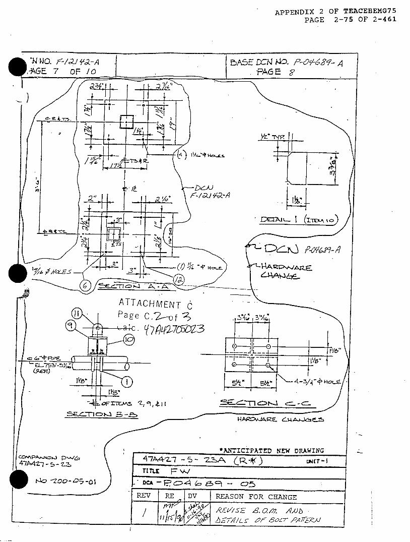
APPENDIX 2 OF TEACEBEMG75PAGE 2-75 OF 2-461
ATTACHMENT CPage C.2-of 'v
Y ?Lf2-76=Y23
- -
C4 zAo-i ps -
4X-7427 - 5 - z-a
*ANTICIPAA7A4Z-7 - S - Z3A (RPITI TL F= W.DCA - . C:4 ( B - °25
REV I RE - DV I REASON FOR CHIANGE
Az7',/SE S. a/;. lX?/-
80L 60PS f Am
£ fxT?.JL-~ I r1 A
11 ---------
-- T l
Qo�'I"n-'q
I
-sD,. ZE--, 4Ak -
too -Zoo-.05-01

APPENDIX 2 OF TEACEBEMG75PAGE 2-76 OF 2-461
011 EBASCO MECHANICPL
Su r°
W~-(4E~z T~-kc ~AQ~
47 A 4?7 -15- 1:2 ~
lP T-H Y-AI
/x V21 O,,- ko
(m\ CV w)
Wx4q qC)
.- CIO.I I I
PTTACHMENT Caae C. , of,Wc. Y74Lp2-70)3
- �0��k4/t�6L)
P. 211. 6.1992 16:43
(C- U�sc:)(-T-5
T�r 1-y-el -v-
.5-f t �-
zzIi
i
ii
iI

'-4 7AM4Z-7- 2 --23
U~ ~IN~ so "svv\
,-I -- s - -2 13- , �) K, 7 � 1, � (-" C- �- K,< -
APPENDIX 1 OF TEACEBEMG74
PAGE 1-500 OF 1-646
APPENDIX 1 OF TEACEBEMG74PAGE 1-501 OF 1-646
ROBE3RT L. CLOUD ASSOCLATES, INC.
BY.A4 DAT(912"A5 Suppot No. PAGE NO. l OF 2-11CD4ZDAT Q WBN U-Bolt Evaluation ,PROJ. NO. M3
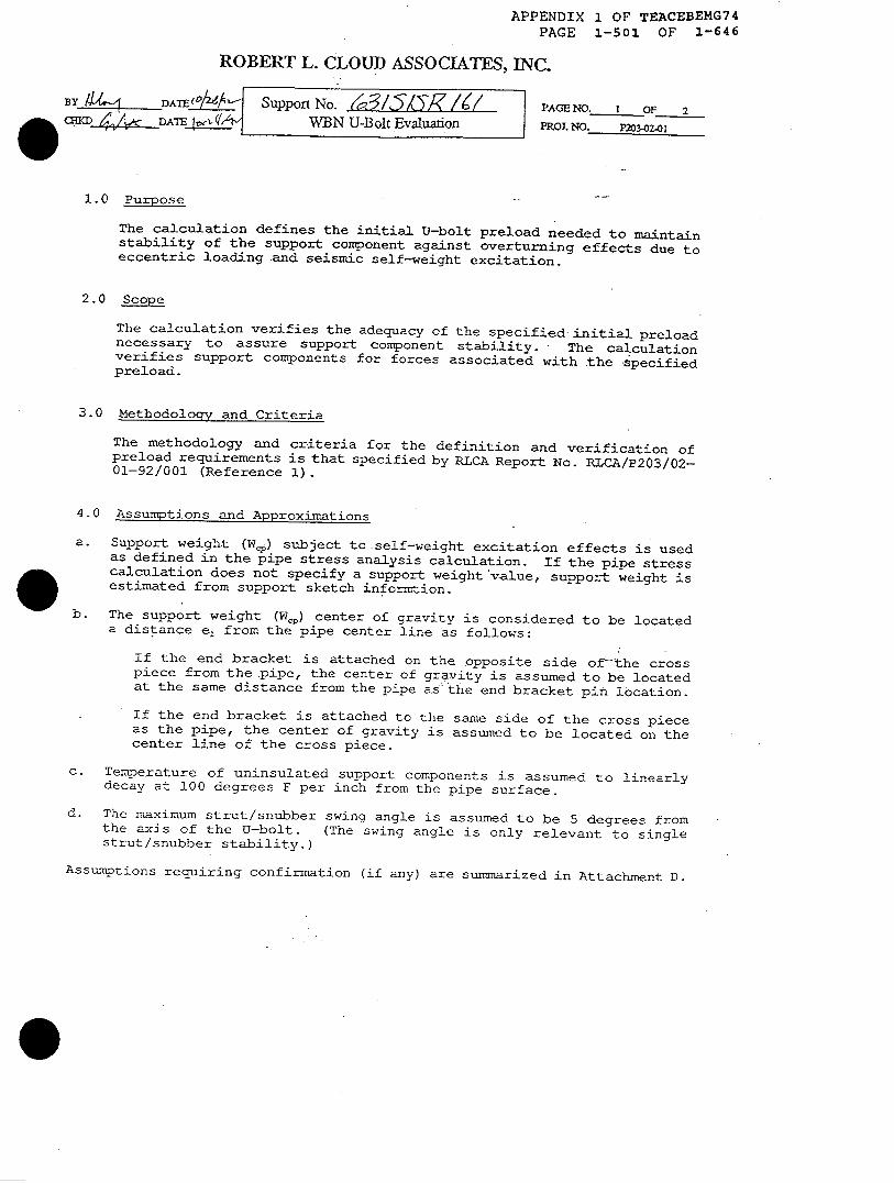
1.0 Purpose
The calculation defines the initial U-bolt preload needed to maintainstability of the support component against overturning effects due toeccentric loading and seismic self-weight excitation.
2.0 Scope
The calculation verifies the adequacy of the specified initial preloadnecessary to assure support component stability. The calculationverifies support components for forces associated with the specifiedpreload.
3.0 Methodology and Criteria
The methodology and criteria for the definition and verification ofpreload requirements is that specified by RLCA Report No. RLCA/P203/02-01-92/001 (Reference 1).
4.0 Assumptions and Approximations
a. Support weight (We,) subject to self-weight excitation effects is usedas defined in the pipe stress analysis calculation. If the pipe stresscalculation does not specify a support weight value, support weight isestimated from support sketch informtion.
b. The support weight (W,) center of gravity is considered to be locateda distance e, from the pipe center line as follows:
If the end bracket is attached on the opposite side of-the crosspiece from the pipe, the center of gravity is assumed to be locatedat the same distance from the pipe as -the end bracket pin location.
If the end bracket is attached to the same side of the cross pieceas the pipe, the center of gravity is assumed to be located on thecenter line of the cross piece.
c. Temperature of uninsulated support components is assumed to linearlydecay at 100 degrees F per inch from the pipe surface.
d. The maximum strut/snubber swing angle is assumed to be 5 degrees fromthe axis of the U-bolt. (The swing angle is only relevant to singlestrut/snubber stability.)
Assumptions requiring confirmation (if any) are summarized in Attachment D.
APPENDIX 1 OF TEACEBEMG74PAGE 1-502 OF 1-646
ROBERT L. CLOUD ASSOCIATS, INC.
BYJ- DTEWŽLL- Support No. ; PAGE NO. 2. 4 24 DATE__ WBN U-Bolt Evaluation PROJ. NO. P23-02- 1
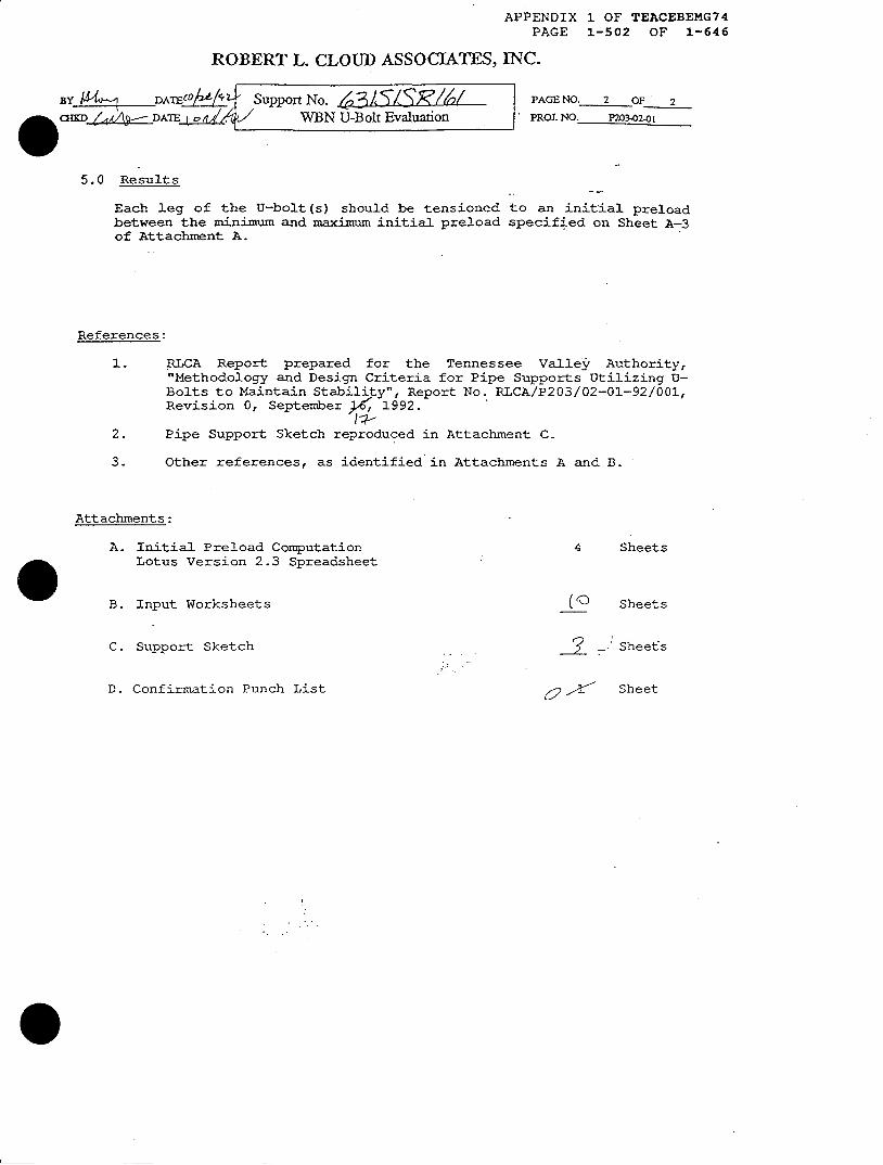
5.0 Results
Each leg of the U-bolt (s) should be tensioned to an initial preloadbetween the minimum and maximum initial preload specified on Sheet A-3of Attachment A.
References:
1. RICA Report prepared for the Tennessee Valley' Authority,"Methodology and Design Criteria for Pipe Supports Utilizing U-Bolts to Maintain Stability", Report No. RLCA/P203/02-01-92/001,Revision 0, September ) 1992.
2. Pipe Support Sketch reproduced in Attachment C-
3. Other references, as identified in Attachments A and B.
Attachments:
4 SheetsA. Initial Preload ComputationLotus Version 2.3 Spreadsheet
(eB. Input Worksheets
C. Support Sketch
Sheets
? - :Sheefs
O , SheetD. Confirmation Punch List

Robert L. Cloud and Associates. Inc.TVA Watts Bar Nuclear Plant
Single Strut/Snubber Support No.63-1SIS-R1161 '-
APPENDIX 1 OF TEACEBEMG74PAGE 1-503 OF 1-646
Attachment A
By: 4. Date: (o/ Z6- Caic. No.: 63-1SIS-11161
Chid: 5 .Date: 3C .-L- 2, Proj. No.: P203-02-01
n N v N -Neef.]
; nt- css A-hlik (alcr Nol/Rev.: N3-63-0iA/ 12 Node No.: B76
Outside DiarneterWall ThicknessMaterialDesign PresssureDesign Temperature
E-ModulusYield Strength
U-Boht(s) Rod DiameterLeg CL to CLNet Stress Area (one leg)No. of U-BoltsShirn Plate ThicknessStanchion HeightStanchion WidthMean Stanchion Temp.U-boit MaterialDesign TemperatureE-ModulusYield StrengthMean U-Bolt Leg Temp.
Cross PieceandEnd Bracket
DT
PoTo
E(p)Sy(p)
dK" dirnenAtntHBcTs
TuE(u)Sy(u)Tubg
Section: PL',COMPACThOTHER
Height h
Width W
Bracket Length 'B dimen
Half length of End Bracket L2
Remaining Half Length Li
Mom of Inertia, cross piece I1Mom of Inertia @ bracket 12
Sec. Area, cross piece Al
Sec. Area @ bracket A2Cross Piece Material
Design Temperture Tc
E-Modulus E(x)
Yield Strength Sy(c)
Shear Area Coef. I
Self-Wt Support Wt., EffectiveExcitation Acceleration, Parallel
Acceleration, PerpendicularEccentricity, On AxisEccentricity, Offset
Strut Load Max. Design LoadEccentricityAngle
Coefficient ofThermalExpansion
PipeU-Bolt (Bend Section)
U-bolt (Mean Leg)StanchionX-Piece
Wcpala2el
e2
ATheta
@ 400@ 400@ 150@ 200@ 100
Input Data
21 -Oct-92
Pipe
-j- --- ---- - ---- -- -
14.000 in0.375 in
SA-358 TP 304 -600 psi400 deg F.-
26,600,000 psi20,700 psi
0.88 in'15.00 In0.462 In
2
2 ,-0.00 In3.75 in -4.50 In -
200 deg FASTM A36 -
400 deg F
27,000,000 psi30,800 psi
150 deg F
PL0.75 in-'
19.00 in3.50 in",1.75 in5.75 in0.67 in
4
19.50 in4/14.25 In2
19.10 in 2'-ASTM A36-
100 dleg F
27,900,000 psi36,000 psi
1.20 -'
130 lbs '0.81 g-3.08 g ,
11.02 in-0.00 in
13623 lbs7.75 in
2.5 deg
9.59E-06 infin/deg F6.82E-06 inrn/deg F6.25E-06 in/in/deg F
6.38E-06 in/in/deg F
6.13E-06 in/in/deg F
WBN-US5Page A-1 of 4
-
Ref 3Re1 3Ret 3Rel 3Ret 3
Ref 3Rel 5.a
Ref 6aRet 6aUNC SeriesRet 4Ref 4Ref 4Rel 4
Ref 6a
@ PipeRef S.dRef 5.e
Ref 4Ref 4Ret 6
(EV2)(K(212)
@ end bM edgeRef;S.dRef S.eRef 2a. pg 39
Ref3Rel 4Ref 8, Par 3.6b
ReftS.cRef 5.cRet S.cRet S.cRel 5.c
CC(Z(Z
(I

Robert L. Cloud and Associates. /nc.TVA Watts Bar Nuclear Plant
Single Strut/Snubber Support No.,63-1 SIS-R1 61
By: 91•4 . Date: (v 2/2 r-Chk'd :,: tDo: 1
APPENDIX 1 OF TEACEBEMG74PAGE 1-504 OF 1-646
Attachment ACaIc. No.: 63-1SIS-R161Proj. No.: P203-02-01
Coefficients Relaxation FactorDesign Factor
U-bolt Preload(Cold)
MinimnumPreloadRequired
To MaintainU-boltTension
U-bolt Force Req d
Add. U-bolt Force Req dfor Self-Wt Excitation
U-bolt Force Req'd
Minimum DesignU-bolt Preload (Cold)
Minimum InitlalU-bolt Preload (Cold)
Stability FrictionCoefficients Load distr factor
of external loads
Stiffness Cross piece
U-boltCross Sedcion AreaUpper Bound StiffnessLower Bound Stiffness
Clamp (X-plece + U-bolt):Clanp Stiffness, MaxClanp Stiffness, Min
Pipe Stiffness
Resultant StiffnessMaximumMinimum
For Stability U-Bott Force Req d
Add- U-bolt Force Req'dfor Self-Wt Excitation
Min Preload Req d
Page A-2 of 4
RFDF
'Mualpha
Kc
AuKulKu2
KclmaxKcl,min
Kp
KmaxKmin
Uo,p
Uo,x
Uo
U1 'p
Ul x
Ul
U,d(Min)
U,l(Min)
DesignPreload
InitialPreload
0.21:5
0.161.4
: -.....g: . X=........ '. s.:
1.203 in2
2801,334 lb/in90,600 Wb/in
183,183 Rlin94,155 lb/in
169,135 fb/in
87,940 Ib/in60,484 lb/in
438 lbs
1,458 lbs
1 896 lbs
2607 lbs
20 lbs
g.,2 Ibs
1 314 lb
1,577 lbs
PRef.]
Re1 1, Sec 4.3.4Ret 1, Soc 4.3.5
Ret 1, Sec 4.3.6Ref 1, Sec 4.3.7
Reo 1, Eq 10Rel 1, Eq 11
Kc & KuKc & Ku
Ref 1, Eq 7
Kd&KpKd&Kp
Ref 1, Eq 2
Ref 1. Eq 3
Ref 1, Eq 4
from Ro1l, Eq 5
from Ret 1, Eq S
Ret 1. Eq 5
Ret 1, Eq 6
Ret 1, Eq 1
WRBN-USS 21 -Oct-92
Robert L. Cloud and Associates. Inc.TVA Watts Bar Nuclear Plant
Single Strut/Snubber Support No.
63-I SIS-R1 61
APPENDIX 1 OF TEACEBEMG74PAGE 1-505 OF 1-646
Attachment A
By: t Date: (°/ et |Calc. No.: 63-1SIS-R161
Chk'd:i 4 ... , Date: ,j j' z Proj. No.: P20302-01 eChk'd: ~ Ref.]
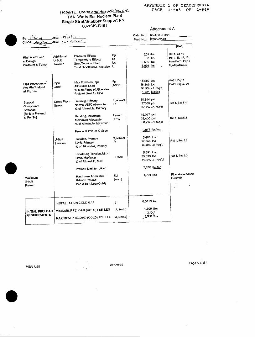
MinU-boltLoad Additional Pressure Effects Up 209 lbs Ref 1,Eq 16
st fsgn U-Bol Temperature Effects Ut 0 lbs Pef 1, Eq 14.15
Pressure &Termp. Tension StrutTension Effect Us 2,530 lbs fromReflEq17
Total U-bolt foroe, one side U 5.891 lbs , U.;Jp+UP+US
Pipe Acceptance(tor Min Preloadst Po, To)
SupportComponentStresses(for Min Preloadat Po, To)
Max Force on PipeAllowable Load
% Max Force of AllowablePreload Limit for Pipe
Cross Piece Bending, Primary
Stress Normal AISC Allowable% of Allowable, Primary
Bending, MaximumMaximum Allowable
% of Allowable, Maximun
Fp2/3'Pc
fb,normalFb
fb,max.9'Sy
Preload Limit for X-iece
U-BoKt Tension, Primary
Tension Limit, Primary% of Allowable, Primary
U-bolt Leg Tension, Max
Limit, Maximun% of Allowable, Max
Preload Limit for U-boft
Maximum AllowableU-bolt PreloadPer U-bolt Leg (Cold)
ftnormalFt
Ftmax
U,l(max)
15,287 lbs16,103 lbs94.9% <1 req'd1,~781 O-Aelq
18,344 psi27000 psi67.9% <1 req'd
19,017 psi32,400 psi58.7% <1 req'd
2.917 tbs/leq
5,683 lbs17,066 lbs33.3% <1 req'd
5,891 lbs25,599 lbs23.0% <1 req'd
7 268 Lbs/_oq
1,781 lbs
Ref 1, Eq 18Ref 1. Eq 19, 20
Ref 1, Sec 5.4
Ref 1, Sec 5.4
Ref 1, Sec 5.3
Ref 1, Sec 5.3
Pipe AcceptanceControls
Page A-3 of 421 -Oct-92
PipeLoad
MaximumU-boltPreload
WBN-US5
INSTALLATlON COLD GAP 9 0.0313 In
INfnIAL PRELOAD MINIMUM PRELOAD (COLD) PER LEG Ujl (min) 1,600 Ibs
REQUIREMENTS ( 43~
MAXIMUM PRELOAD (COLD) PER LEG Ujl (max) J.e0-b-
APPENDIX 1 OF TEACEBEMG74
RobertL. Cloud and Associates, Inc. PAGE 1-506 OF 1-646
TVA Watts Bar Nuclear PlantSingle Strut/Snubber Support No.
63-1 SIS-R1 61Attachmenlt A
By: ete: 4 C'L, Calc. No.: 63-1SIS-R161
Cbk'd: / 04Date Do '_ H < EProj. No.: P203-02-01
[fRa.]
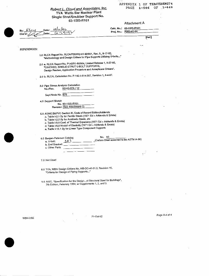
REFERENCES:
1.0 RLCA Report No. RLCAIP2O302-01-921001, Rev. 0, 9-17-92
.Methodology and Design Critiera for Pipe Supports Utilizing U-bolts...
2.0 a. RLCA Report No. P142/01468004, ULmited Release 1. 8-27-92.
-CINCHED, SINGLE-STRUT U-BOLT SUPPORTS,
Design Review, Application Procedure and Acceptance Critiera".
2L0 b. RLCA, Calculation No. P-142-1-514.007, Revision 1, 8-4-87.
3.0 Pipe Stress Analysis CalculationNoJRev. N3-63-07A 1 12
Supt Node No. B76
4.0 Support SketchNo. 63-1SIS-R161
Revision (See Attachment C)
5.0 ASME B&PVC Section 111, Code of Record Edition/Addenda
a. Table I-2.1 Sy for Ferritic Steels (1971 Ed + Addenda & Errata)
b. Table 1-2 2 Sy for Austinetic Steels, etc
c. Table 1-5.0 Coef. of Thermal Expansion (1971 Ed + Addenda & Errata)
d. Table 1-6.0 Moduli of Elasticity (1971 Ed + Addenda & Errata)
e. Table 1-13.1 Sy for Linear Type Component Supports
6.0 Bergen-Paterson Catalog No. 80
a. U-bott: _,t 3 (Carbon Steel assumed to be ASTM A-36)
b. End Bracket:c. Other Parts
7.0 Not Used
8.0 TVA, WBN Design Critiera No. WB-DC-40-31.9, Revision 15.
Criteria for Design of Piping Supports..."
9.0 AISC, 'Specification for the Design...of Structural Steel for Buildings',
7th Edition, Feburary 1969, wI Supplements 1, 2, and 3.
WBN-US5 21-Oct-92
Page A-4 of 4

APPENDIX 1 OF TEACEBEMG74PAGE 1-507 OF 1-646
- Robert L. Cloud and Associates, Inc.TVA Watts Bar Nuclear Plant
Single Strut/Snubber Support No.
I ,- I st 5-Rla/(I
BrI 1 t Date: i fz / C
tw-LsL'At" p
Attachment B
Page-E | of (
alc. No-: +A4
F70 No: P2W3-02-i
Pipe Seess Aralyrs Cnk. NoJroe.:
pipe Outside Diameter
Wall Thickness
Material
Design Presssure
Design TempeatureE-t1odutu6
- Yield Stength
U-Bolt(s) Rod Diameter
Leg CL 10 CL
Net Stress Area (one leg)
No. of U-Bolts
Shim Ptate Thickness
Stanchion Height
Stalnchion WKidh
U-bolt Material
Desigon lempeure aeE-ModulusYield Seength
Cross PIece Sdcion :PL.'COMPACT.
and Height
End Bracket Wdth
Bracket Length
Haft length of End Bracket.lemnaining Half Length
Momof Inertia. crov; PieoF
Moom of Inertia @ bracket
Sec. Area. crow; piece
Sec. Aea @ bracket
Material
Design TempertueE-ModulusYield Scength
Shear Area Coet.
Saf-WL Support WL. EHesecrve
E-ritation Acceleration. Paralel
Acoeleration. Perpendocula
Ecceniricity. On Avis
Ecceniviity. Offset
Stut Load Max Design Load
Eccenre icity
Angle
Coeitficoent of PipeThemal U-DollExpansion X-Piece
it3/3 ° oNodr No.:
D lA,o o' in ' Rf3 Inputactual I
T 3~-37-in Rctt vut°<Ss nu
i3S_6 -_ F( Inputfor inro
Po 600 pa.- R3 n hput
To o drgF Rot InputE(P) Eis Jae Jt71s Rct V,1l61' LookuptableSy(p) t Eo 0K5a6+I.nJI4Je Rd5.. 20.1 1 Lootkup table
d Rct6. Input
Kdimen /. 0o i| Rct6. InputAt roosKo20-UZZ2t UtNc serb Computed fon Z Rd- Input number
0 n Rd4 hiput i applic
H -3. in Rct4 nput ifapplic
Ec 5 RctA 4if6 Plr5putstanonS
3(0 R . Inp. puttoriifor,
+Fr. /57 OF i rip. Typ same asE(u) @c..08taMtaEWrsa z.n. Rf 5d Lookup tableSy(.) Ms.8tE- c.rs-Frsa- Rd5j Lookup table
.07THE~R Input as alt C1
h O.7 5 RdtI Input
W t O' ill h d Input
S'dmen 3. in Rc16 InputL2 .E3512 in (B/b) Computed froLi +E21t2-E36 in (l12-L) Computed
11 cr ,- h r^ 4 Computedtor
Q jcS i^4 Input I of X-pi
Al in^2 Computed tor
A2 0 ,- I n2 kputAotX-p
3rs ( hInput tor intorn
Tc - c deog F e ed bhrin d. Asume 1 OOO
E(4 a Ee+9 lopJ~g Rcd5SA Look up table
Sy(c) tOtecr+O * s RefS, Look up table
S Ref2a, 5639 1.2 for plates:
Input acceleral
ra1 Inputasoeleral
ra2 .9 9 A2, A3 Input SRSS oft
e1 1 i/ Input
e2 f . in Input it non-ze
P IIn RoS Iput envelope
A 1.75 ,/ R A Inpul (see Fig 1
Theta z g doeg Rof8,?.,S6b I nputlfdegtyp
se'rresci, otei t Rcr.5 Lookup table tc
@t00%tevs00 Rob5l Lookup table icevoo~a~s.otEso.yes Ras. Lookup table tc
D0I tO
rmation
for A1O Cir 8for Al 085 G B
r UNC thyeads
of U-bolts
able
able /t. 7 t Z 3.1 5
on width (pipe bearing Iergt i applic.
mationspip temperatrefor A36for A36
iPS
PFL sections' put it noL F(jltd- FL
ece and bracket f.JI hoc-L>,
PL section:InputifnolPL r I ,ry4E5 iiece and bracket A. • ZT.
maAtion i, e5-f tdegn leomperatue reduction: tor A31; 4 0 -r4 2 O l&5//o.J//Lfftor A3S
see rot tor other sections
aon in strut directoon
ion in sut direction
accelerations in non-strut cke*nrs
support load
1(a) o methodology)
or Carbon Steelor Carbon Material Group Aor Carbon Materiat Goup A
kut Data
2Aj , /
.'iN-USt
APPENDIX 1 OF TEACEBEMG74
PAGE 1-508 OF 1-646
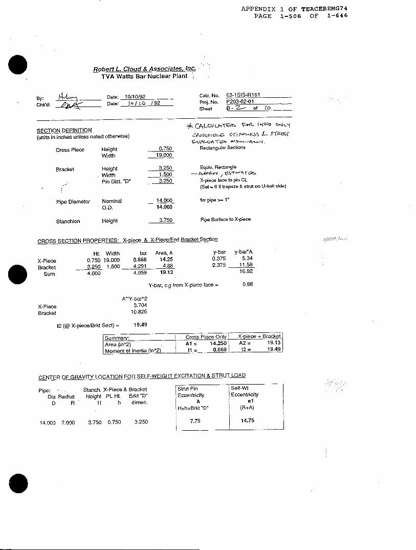
Robert L. Cloud & Associates. Inc.TVA Watts Bar Nuclear Plant ;
By:ChKd:
Date: 10/10/92Date: lo/ c3 /92
SECTION DEFINITION(units in inches unless noted otherwise)
Cross Piece HeightWidth
Bracket Height. Width
Pin Dist. 'D'
Pipe Diameter NominalO.D.
Stanchion Height
0.75019.000
3.2501.5003.250
14.00014.000
3.750
Caic. No. 63-1SIS-R161Proj. No. P203-02-01Sheet B- ZZ- of f o
CWW 11HL I-lo 0~4"
1,rJvA -G f A--Rectangular Sections
Equiv. Rectangle
X-piece face to pin CL(Set - 0 if trapeze & strut on U-bolt side)
for pipe >- 1'
Pipe Surface to X-piece
CROSSSECTION PROPERTIES: X-piece & X-Piece/End BracketSection
lxx Area, A0.668 14.254.291 4.884.959 19.13
y-bar y-barA0.375 5.342.375 11.58
16.92
Y-bar, c.g from X-piece face =
X-PieceBracket
12 (@ X-piece/Brkt Sect) =
0.88
A'Y-barA23.704
10.826
19.49
Summary: Cross Piece Only | X-piece + BracketArea (in2) , A= 14.250 A2 = 19.13Moment of Inertia (in2 = 0.6681 12 = 19.49
CENTER OF GRAVITY LOCATION FOR SELF-WEIGHT EXCITATION & STRUT LOAD
Pipe: --Dia Radius
D R
Stanch. X-Piece & BracketHeight PL Ht. Brkt 'D'
H h dimen.
14.000 7.000 3.750 0.750
Strut Pin Self-WtlEccentricity Eccentricity
A el
H+h+Brkt 'D' (R+A)
7.75 14.75
X-PieceBracket
Sum
Ht. Width0.750 19.0003.250 1.5004.000
3,250

APPENDIX 1 OF TEACEBEMG74
PAGE 1-509 OF 1-646
ROBERT L. CLOUD & ASSOCIATES, INC.
BYj 4 .. § DATE N/ 6/k7 Calculation No.CwoD~ /ZZJ .DATE (oz- "-f WBN U-Bolt Evaluation
PAGE NO.- 3. OF tO
PROI. NO. P203-02-01
Attachment B - Input Worksheets
2. Simplified Method . Design Input
2.1 Design Load 13 (o Z3 zt , 3 A/-7 17Z62.2 Lumped Mass /3
Table 4.2.4-1 of Ref .s lstimated p
-7;/Calculated - see follow~ing pages
23 a
/'nter of Gravity -
t~o 14 -- L±:+ /4 +3'5 4-- Single Strut/Snubber (Assumed symnetnic) (See FTg-te 1) 7.7 .
e= 0.0 in. K.
- Trapeze: Struts/Snubbers same side as U-Bolt (See Figure 2)
e= (R + A) = uin.
e- 0.0 in. for symmetric= 0.5Q - T| for unsymmetric= in.
- Trapeze: Struts/Snubbers opposite side of U-Bolt (See Figure 3)
el = (R + _A) = ine, = 0.0 in for symmetric
= 1O5Q - T| for unsymmetric
=_in.
Calculated - see following pages
1
FIre 1: Sigk Strt Codfigumrtio Figumr 2. Trp=z~ - S~ Sid.
Corfiguratiol
Figure 3: Trcq- - Oppo-CGfigumio
q -'2" [lle£ 3
[Ref]
APPENDIX 1 OF TEACEBEMG74PAGE 1-510 OF 1-646
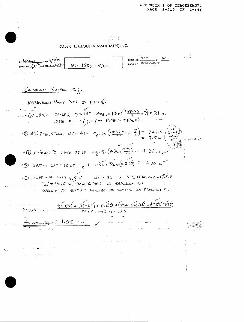
ROBERT L. CLOUD & ASSOCIATES; INC.
SY I 9 JATE ;$ | - PAGE NO. OF __
ByHKDATEb7,h/t^V @ Sl //b PFO . NO,.41
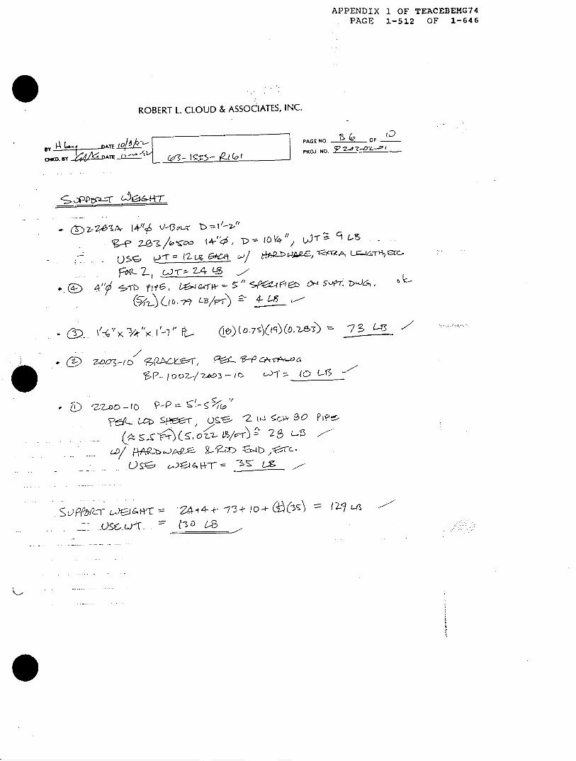
6>ctuLAr5 5t)PPtPZ C..
.Rc,.S,^v XD e- pf &
- * (9 0Us3L $s, c= 1 4,(Mv - 21
U'SC. X ='7 (tr ,'9P-Pm)
~~ L~~ 4 - L-2 c(P~o
01 s- cs tj <-r-7 3 L3 a-.(, /e) ll5a
7-J 003-10 Of-= 10 LSc4Q{o13gt22 14.0o {
2-z-w - 'a p- pj2 Y-. r _ 13 7. UE V 1.b
taH--r c r p Tg P/
. .- .
-, 225 - &) (9,T (7)i-t>5 F 314 Tl t - &1zsEcnvE.4^7SL
t24-- 4 -r- 73-- 0-' 1o 7 ,g5
-A- - . .... . - . .7 3.
.c&,- , 02

APPENDIX 1 OF TEACEBEMG74PAGE 1-511 OF 1-646
ROBERT L. CLOUD & ASSOCIATES, TNC.
BY SLŽ9ATR ,o9' Calculation NO.|
CBED.4ARU ATE -t WBN U-BOlt Eaaion
Attachment B - Input Worksheets
2-4 Accelerations
Case I- HosizontalPipe& Vertcal Suport (See hgue 4)a, = 2. Og a,=5.7 g
Case I - Hoizonl Pipe & Hoizontal Sppot (See Figure 5)a, = 1.O g a, = 6.7 g
cas m - Vertical Pipe & Hoizta Support (See Figure 6)a, = 1.0 g a2 = 6.7 g
Otde Ž S
PAGE NO. 635 OF tD
PROL NO. P203-o01
- 3=07935
I
Fg 4: Case I Figure 5: Case n
2.5 Swing Angle - Single Stnrut/Subber Only
Initial Cold Offset 0 degrees
Installation Tolerance 2.0 degrees
Calculated Movement Swing = 603 degrees
Total Swing = 03 degrees
(See below)
Use Z. I degrees
Calculated Movement Swing:
Maximum Movemert in Unrestrained Direction, MM = i3n3 in (z t .16 -- p.
Pin-Pin Dimension (Use Cold) = (z2 in
Calculated Swing Angle, 0 = tan-' [M/Pin-Pin] = OS<< I degrees
=I (! G1 I7 D S +
APPENDIX 1 OF TEACEBEMG74PAGE 1-512 OF 1-646
ROBERT L. CLOUD & ASSOCIATES, INC.
e 4y Ay -DATE LQIk
CHKD. BY 4w& DATr t -' L@- g5 t
- (E> w~s1+"+ -g bs/->
--- -4 CTA, -rZ
bg- /o *c L/3- 4- I-5 5
I/. ) ZS00'-l D (,E, H 9Cf4
SP- 1 9>/3-O f- 1 gs
(AQt S ~.~ ~ •~
pI i- 1-
SL)AjiI-r L t&*-r =- 4--t4 - - --3+ 0-4- Q -( -4,-
- - IO :L - (- L- /
PAGE NO. L ___ _ OF -
PROJ. NO. 2-I 4 ?Z -{"
C+)(07s}(15(.? 73 L-13 -'/- . I.\ '3 ll >S I ~- /( FL
APPENDIX 1 OF TEACEBEMG74PAGE 1-513 OF 1-646
ROBERT L. CLOUD & ASSOdATES, INC.
Sy -D9nATE 6* l l PAGE PI
C IDY Ds E .2iLL-,V | f - I (L(I L - | PROJ I
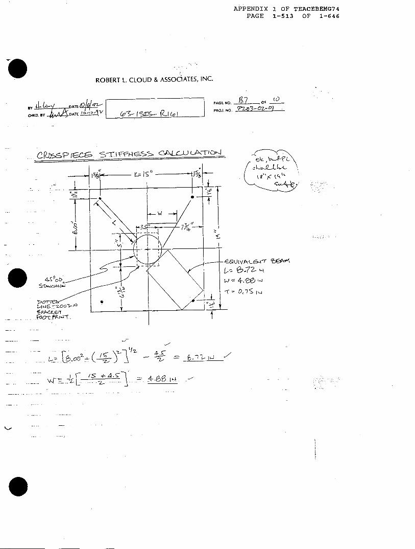
. . C1M5PI£Cs 5Xe=Hl5w
tO. 97 OF 0
-- v,', b-QTL' If
ve"rc t~t
L= ji - = _ £ J-7 lI 4 /
-T
%"r -.- .� �,E � - -= 4- --66-t-l -
APPENDIX 1 OF TEACEBEMG74PAGE 1-514 OF 1-646
ROBERT L. CLOUD & ASSOCIATES, INC.
PAGE NO. _ _- OF -__
ROJ .NO. P2__________
3
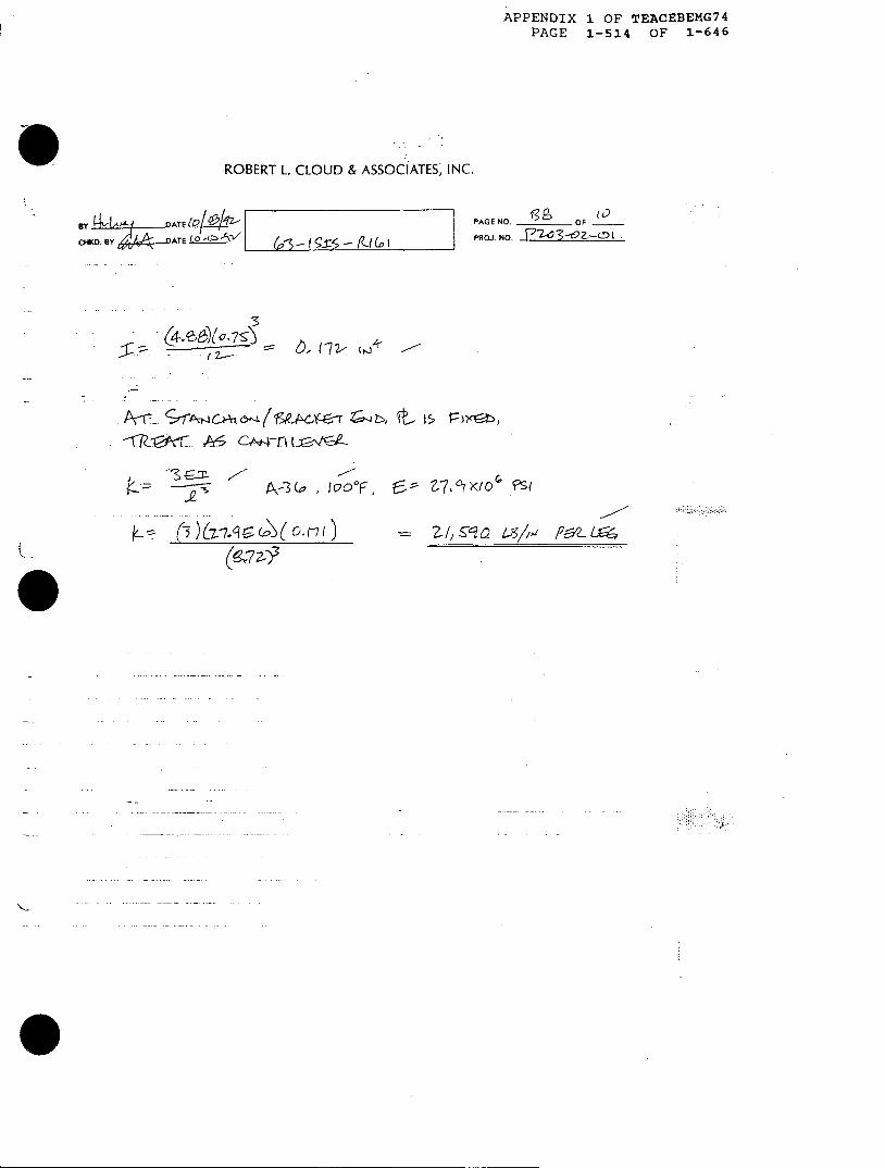
.I (Z =;: te?1s (S e~ 1 "J. 4 --
(2. -- '7''7t- 5
A s'''6 A4 a--, L o L Z,.,e LA's CTXE
.; . I I . ; I . i
6' - I 9-rs- l- c
"IS G= ,-
k- --IS [G
.
BY* AAL4 ATE+ 4zCHO1K. BY 944 -ATE L4--5 I
Z7 A 7l, 5S M//4
P*L LX5~
; .,< .,, ., 5 i

APPENDIX 1 OF TEACEBEMG74PAGE 1-515 OF 1-646
ROBERT L. CLOUD & ASSOClATES, INC.
BY oi (= L DATE X_ l__
CHKD. BYA,/e 4gnATE & - 1 l
PAGE NO. 6__ OF_ OF
PFtOJ. NO. 7-e9o
7f1 S)f -- 7 C -t
C, fQ p, ?~2 C2A$
K.. - :Y'<- o K a
1-77 -11K17-7
C~>~ !~ ,
056 r.: e"',4/ r,~, 7
= I-z-- : ) =
L CZ .':F 6 1() .7 5?
(0, F7) ( 0-- 4 3/7 2-;.1 ./
-/A~K: >~'(O L -- 7
.* UE 6 5f1 FS2 ,Ce
--- co CK104 t
0 C)¢ Pg '~l3As', t-46 I n'&
.~; a:. 1; . si.. .:
4.9
APPENDIX 1 OF TEACEBEMG74PAGE 1-516 OF 1-646
ROBERT L. CLOUD & ASSOCiATES, INC.
BY II" nATE itl1i94 I/
CHKD, BY j,6 -AT`E t~t 51 &- 55-tI
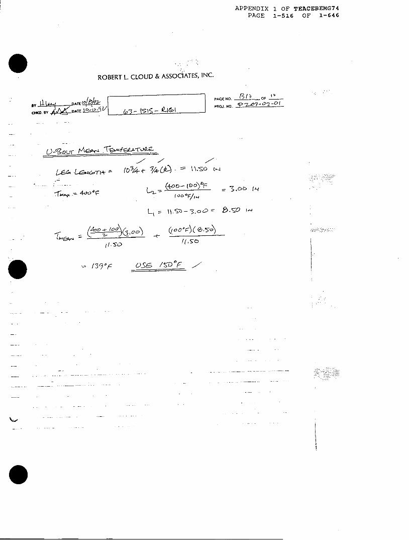
(0 3 4-t- /(4-. - \= \.So (-
L-2- -(4-0G IV 0- 3.oo f'q
L, =~ \1).Sz - -3, c) 0 . t o1
h -4 ~ -,-too
,q. I
PAGE NO. 8 OFI
PROJ.NO. (v 2 w7-a-D 2c
LTI:~-n -
o,-, 0 , r� ( �b, �5-�
it -S-0
= 1 39) DiF V_)e /!9 "F v--
Ii
iIiI

.1
* DMAVO TOt 2BT2TC4
ONSIRUC KD
u ILE s-II
5C5\3aV\l 10.*E323
APPENDIX 1 OF TEACEBEMG74PAGE 1-517 OF 1-646
WALK
~ ~ c-~ TT~A A A.3KED T!
ATACKEN, uL v . i
Pag Ci of
EL E L-< Ut< I A ;OUTRt-
K,,
qt
z
irt
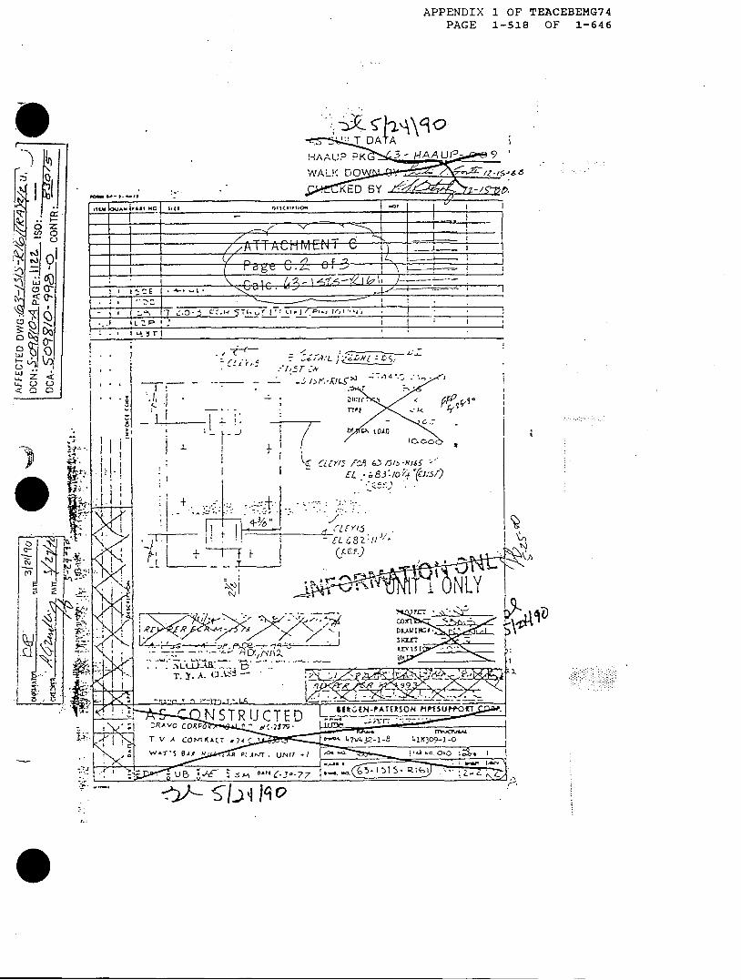
APPENDIX 1 OF TEACEBEMG74PAGE 1-518 OF 1-646
e
0
g-
f -3
0 0 Zq
01
ui ZuiL.) O
< -IF
- I I-i
.1I.
., iI
.- 'L, , °
i / !t a '7. 4 , - .- /) flcj -RL -
- I),s-wg'1 I
- I I.
rypt c<
fno
CLL SfI I -
c iI L7 ~ .6,3 /5/o~~.' N 65 /
+ -. �.- ...- &
-.7.+y 6 u -� (�EYJ5
EL
-�-�F7 F C�E)
* /IIISL
- r x-P
. . Ylj
r ..R
i, ,J 1z-pq"- - - -I. . -,.
T. Y. A. ($ -
. I
:. -f i , c
?\l2.
lz 1
STR U CTED I (-*AEROisttrr-~RAVO C R ,'27 0
T V A COfTAACT 74 C 47V 32-l-8 -0
W^T'S A VJT. UA r f I ) I 't Ol
C7- d ^ -"-t Z 5
I
::.'iE2- -.
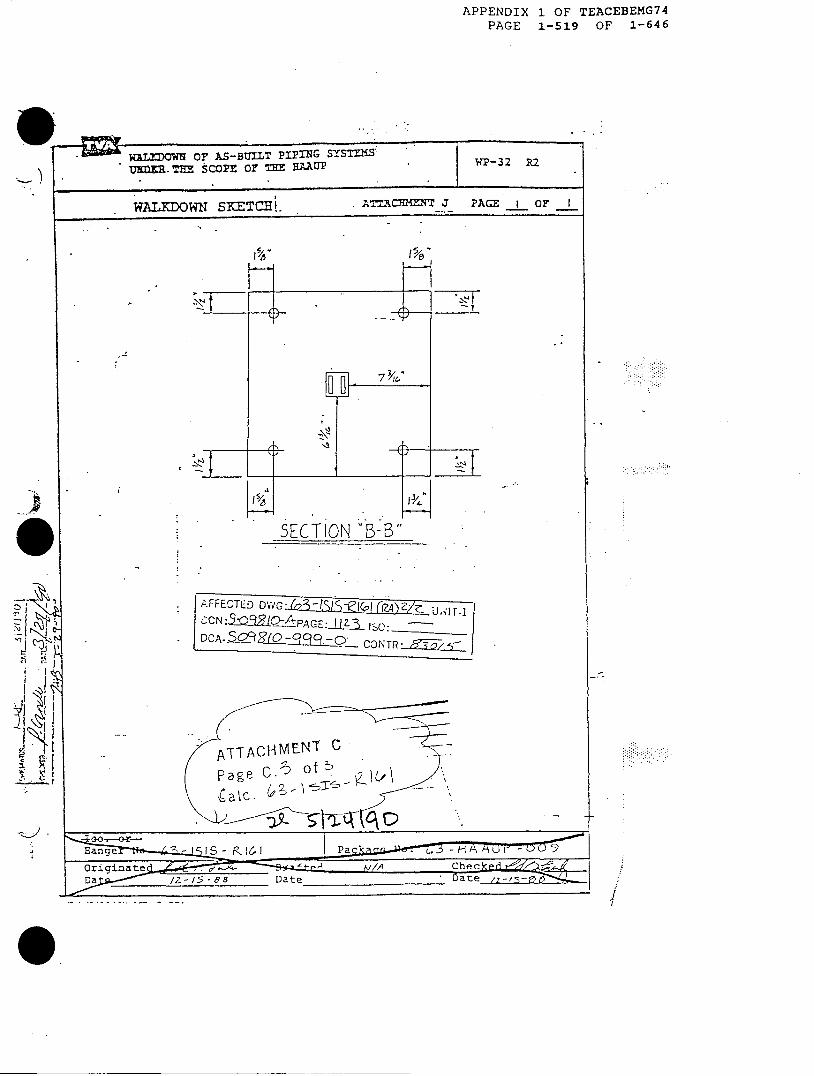
APPENDIX 1 OF TEACEBEMG74PAGE 1-519 OF 1-646
IIhkWALM'O OF AS-BUILT PIPING SYSTNCSIu}m THE SCOPE 0 . n HAAUP
WALKDOWN 'E I
SKETCHL>
I. . - F-
SECTION 'B-B"
A.FFECTED D iG:.ili.ll6~i-~l-
GZCN: 3 9LQAPAGE:Jj ISci:
l DCA- o99rO-- CONTR R
ATTACHMET CPage C.- of "KMc.

tu- I SIS - R IG I OOKINGN C)am-r*T
A ven ( - BET G'~;)

71 EA -B E G 177PA G E 1- 3G:~7 <EL F= 1-si9-
RobertL. Cloud and Associates- Int
IENGINEERING DOCUMENTATION PACKAGE
PROJECT NUMBER:
P203-02-01
DESCRIPTION:
TVA Watts Bar Nuclear PlantPipe Support U-Bolt Stability
Lotus 1-2-3 Release 2.3 for DOS
REV. CHANGES TOTAL ORIGINATINGNUMBER (INCLUDE REVISION LOG PAGES ENGINEER DATE
IF NECESSARY)
Body E nvySH
Attachment A i D.G>-4'-1n/ )v#1
II.I EM
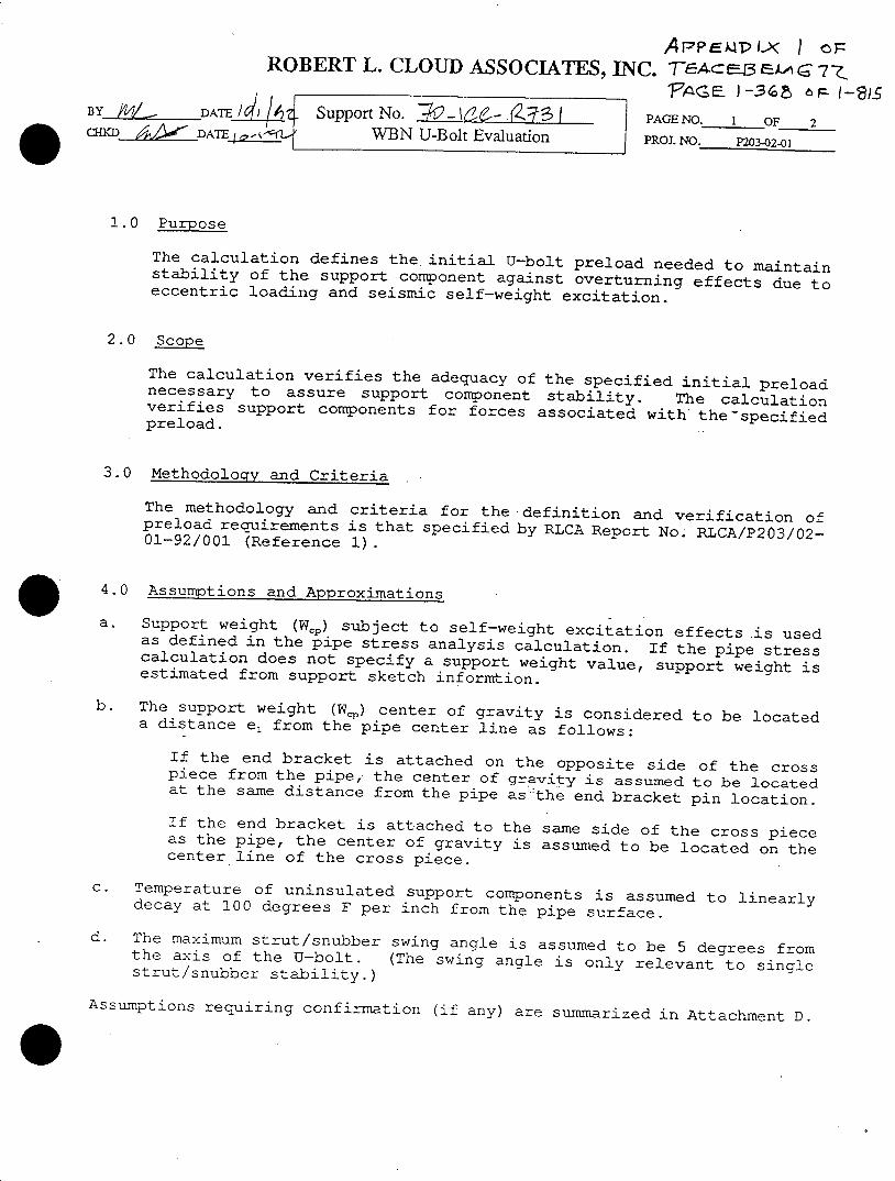
APPEMT'LN I OFROBERT L. CLOUD ASSOCIATES, INC. FeA-cE3 EA 672
FSAGE F -3 6 I 6 F- 1-?IBYJ/Z DATE/ I Support No. R2-16 - R'Z71 PAGE NO. I OF 2
{KD DWBN U-Bolt Evaluation PROJ. NO. P203-024-1
1.0 Purpose
The calculation defines the initial U-bolt preload needed to maintainstability of the support component against overturning effects due toeccentric loading and seismic self-weight excitation.
2.0 Scope
The calculation verifies the adequacy of the specified initial preloadnecessary to assure support component stability. The calculationverifies support components for forces associated with the-specifiedpreload.
3.0 Methodology and Criteria
The methodology and criteria for the definition and verification ofpreload requirements is that specified by RLCA Report No. RLCA/P203/02-01-92/001 (Reference 1).
4.0 Assumptions and Approximations
a. Support weight (Wcp) subject to self-weight excitation effects is usedas defined in the pipe stress analysis calculation. If the pipe stresscalculation does not specify a support weight value, support weight isestimated from support sketch informtion.
b. The support weight (We) center of gravity is considered to be locateda distance e1 from the pipe center line as follows:
If the end bracket is attached on the opposite side of the crosspiece from the pipe, the center of gravity is assumed to be locatedat the same distance from the pipe as the end bracket pin location.
If the end bracket is attached to the same side of the cross pieceas the pipe, the center of gravity is assumed to be located on thecenter line of the cross piece.
c. Temperature of uninsulated support components is assumed to linearlydecay at 100 degrees F per inch from the pipe surface.
d. The maximum strut/snubber swing angle is assumed to be 5 degrees fromthe axis of the U-bolt. (The swing angle is only relevant to singlestrut/snubber stability.)
Assumptions requiring confirmation (if any) are summarized in Attachment D.
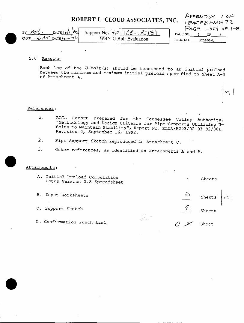
BYJ DATEalDMi_ f DATh (o--
APPF44D r< / oP-ROBERT L. CLOUD ASSOCIATES, INC. 7,4.<ES Esco 7 Z-l - apAq rn [-3199 d F 1-8~
Spo Noe 0-Ie- go 'i PAGE NO. 2 OF 2WBN U-Bolt Evaluation I PROJ. NO. P203-02-01
5.0 Results
Each leg of the U-bolt(s) should be tensioned to an initial preloadbetween the minimum and maximum initial preload specified on Sheet A-3of Attachment A.
<ri
References:
1. RLCA Report prepared for the Tennessee Valley Authority,"Methodology and Design Criteria for Pipe Supports Utilizing U-Bolts to Maintain Stability", Report No. RLCA/P203/02-01-92/001,Revision 0, September 16, 1992.
2. Pipe Support Sketch reproduced in Attachment C.
3. Other references, as identified in Attachments A and B.
Attachments:
A. Initial Preload ComputationLotus Version 2.3 Spreadsheet
4 Sheets
B. Input Worksheets
C. Support Sketch
Sheets y-; A
Sheets
D. Confirmation Punch List0x SheetSheet
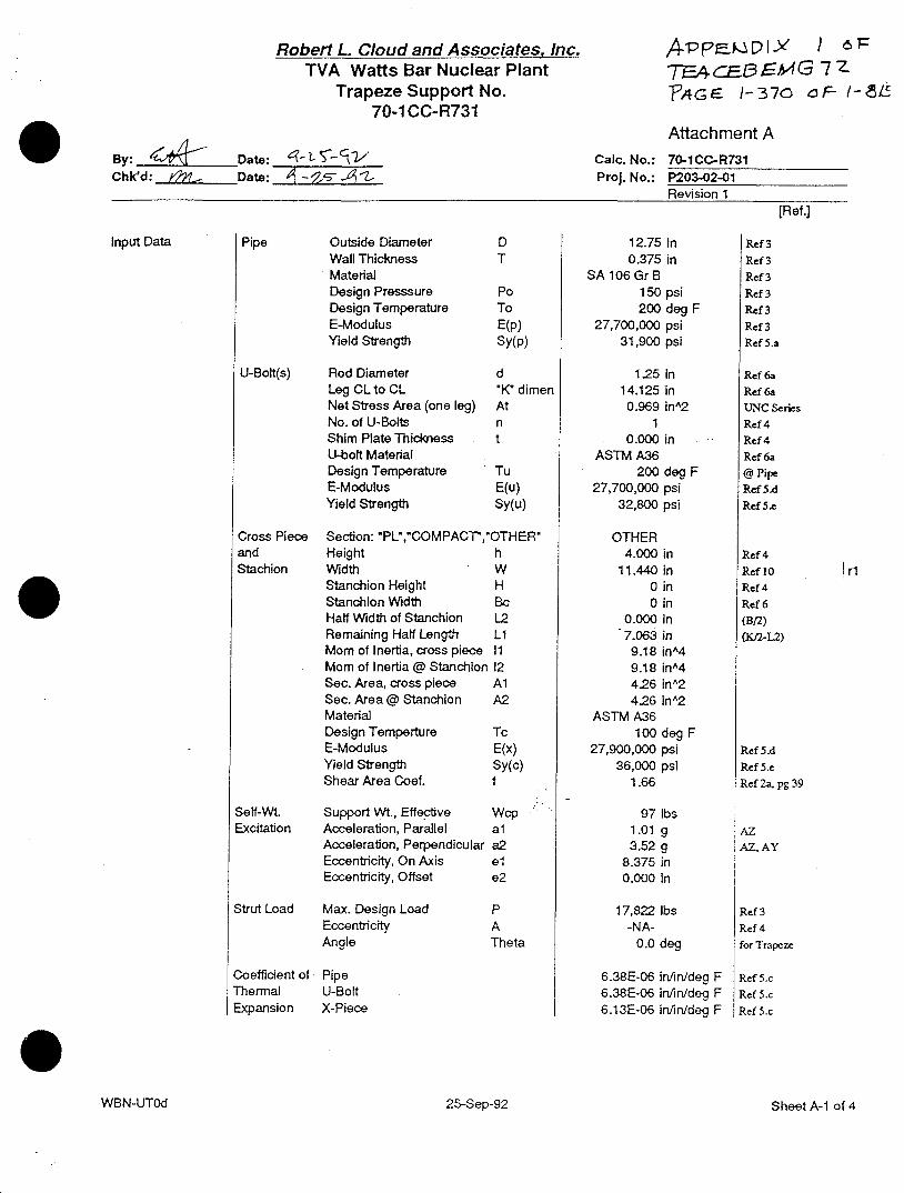
Robert L. Cloud and Associates, Inc.TVA Watts Bar Nuclear Plant
Trapeze Support No.70-1 CC-R731
Attachment ACaIc. No.: 70-1CC-R731Proj. No.: P203-02-01
Revision 1[Ref.]
Pipe Outside DiameterWall ThicknessMaterialDesign PresssureDesign TemperatureE-ModulusYield Strength
U-Bolt(s) Rod DiameterLeg CL to CLNet Stress Area (one leg)No. of U-BoltsShim Plate ThicknessU-bolt MaterialDesign TemperatureE-ModulusYield Strength
Cross PieceandStachion
DT
PoToE(p)Sy(p)
d'K dimenAtnt
TuE(u)Sy(u)
Section: 'PL','COMPACT,'OTHER'Height hWidth WStanchion Height HStanchion Width BcHalf Width of Stanchion L2Remaining Half Length LIMom of Inertia, cross piece 11Mom of Inertia @ StanchIon 12Sec. Area, cross piece AlSec. Area @ Stanchion A2MaterialDesign Temperture TcE-Modulus E(x)Yield Strength Sy(c)Shear Area Coef. f
Self-Wt. Support Wt., EffectiveExcitation Acceleration, Parallel
Acceleration, PerpendicularEccentricity, On AxisEccentricity, Offset
Strut Load Max. Design LoadEccentricityAngle
Coefficient ofThermalExpansion
Wcpala2ele2
PATheta
PipeU-BoltX-Piece
Input Data
WBN-UTOd
A-PP Dc'Iy / 6TFhcEL13A4G 7ZPAGE 1-370 aF I- Lr
12.75 In0.375 in
SA 106 Gr B150 psi200 deg F
27,700,000 psi31,900 psi
1.25 in14.125 in0.969 inA2
10.000 in
ASTM A36200 deg F
27,700,000 psi32,800 psi
OTHER4.000 in
11.440 in0 in0 in
0.000 in7.063 in9.18 inA49.18 inA44.26 inA2426 inA2
ASTM A36100 deg F
27,900,000 psi36,000 psi
1.66
97 lbs1.01 g3.52 g
8.375 In0.000 in
17,822 lbs-NA-
0.0 deg
6.38E-06 in/in/deg F6.38E-06 infin/deg F6.13E-06 in/in/deg F
Ref 3
Ref 3
Ref 3
Ref 3
Ref 3Ref 3Ref 5.a
Ref 6aRef 6aUNC SeriesRef 4Ref 4
Ref 6a@ PipeRef S.dRef 5.c
I riRef 4
Ref 10Ref 4
Ref 6(B/2)
(a-I2)
Ref 5A
Ref 5.eRef 2,a, pg 39
AZAZAY
Ref 3Ref 4
for Trapeze
Ref S.cRef S.c
Ref S.c
By: 4 94 Date: 'q-l oSChk'd: Date: 77 -Sit= -%
25-Sep-92 Sheet A-1 of 4
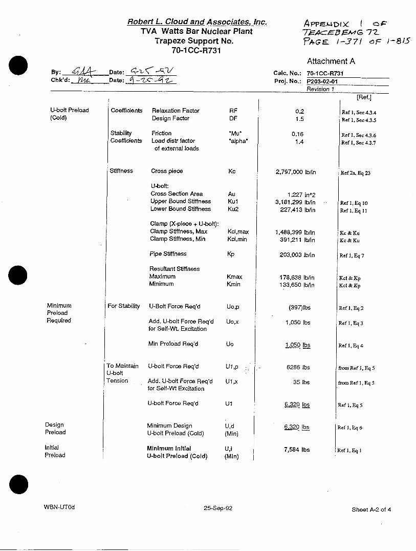
Robert L. Cloud and Associatesq Inc.TVA Watts Bar Nuclear Plant
Trapeze Support No.70-1 CC-R731
By: 4 Date: ~- -V
Chk'd: J Date: _ -C--q Z
U-bolt Preload(Cold)
MinimumPreloadRequired
DesignPreload
InitialPreload
Coefficients Relaxation FactorDesign Factor
Stability FrictionCoefficients Load distr factor
of external loads
Stiffness Cross piece
U-bolt:Cross Section AreaUpper Bound StiffnessLower Bound Stiffness
Clamp (X-piece + U-bolt):Clamp Stiffness, MaxClamp Stiffness, Min
Pipe Stiffness
Resultant StiffnessMaximumMinimum
For Stability U-Bolt Force Req'd
Add. U-bolt Force Req'dfor Self-Wt. Excitation
Min Preload Req'd
To Maintain U-bolt Force Req'dU-boltTension Add. U-bolt Force Req'd
for Self-Wt Excitation
U-bolt Force Req'd
Minimum DesignU-bolt Preload (Cold)
Minimum InitialU-bolt Preload (Cold)
RFDF
'Mualpha'
Kc
AuKulKu2
Kcd,maxKcd,min
Kp
KmaxKrnin
Uo,p
Uo,x
Uo
U1,p
U1,x
Ul
U,d(Min)
U,l(Min)
7=AC,.EMG 7ZPAGE 1-37/ 6F )
Attachment ACalc. No.: 70-1CC-R731Proj. No.: P203-02-01
Revision 1rRef.]
0.21.5
0.161.4
2,797,000 lb/in
1.227 inA23,181,299 lb/in
227,413 Ib/in
1,488,399 lb/in391,211 lb/in
203,003 lb/in
178,638 lb/in133,650 lb/in
(397)lbs
1,050 lbs
10_5 0 Lbs
6286 lbs
35 lbs
6.2 lbs
6,320 lbs
7,584 lbs
-81/
Ref 1, Sec 43.4Ref 1, Sec 43.5
Ref 1, Sec 43.6Ref 1, Sec 43.7
Ref 2a, Eq 23
Ref 1, Eq 10Ref 1,Eq 11
Kc & KuKc & Ku
Ref 1, Eq 7
Kc1 & KpKcI & Kp
Ref 1, Eq 2
Ref 1, Eq 3
Ref 1, Eq 4
from Ref l, Eq 5
from Ref 1, Eq 5
Ref 1. Eq5
Ref 1, Eq 6
Ref 1, Eq I
WBN-UTOd 25-Sep-92 Sheet A-2 of 4

Robert L. Cloud and Associates, Inc.TVA Watts Bar Nuclear Plant
Trapeze Support No.70-1 CC-R731
A4Pff--"4 ix
PAEB 1-372
Attachment A-Y. g-eAr-7 Uate: VL.'\' ' Calc. No.: 70-1CC-R731Chk'd: JtDate: f - Proj. No.: P203-02-01
Revision 1
[Ref.]Min U-bolt Load Additional Pressure Effects Up 84 lbs Ref 2a, Eq 26at Design U-Bolt Temperature Effects Ut 302 lbs Ref 2b, Sec 4.3bPressure & Temp. Tension Strut Tension Effect Us 5,601 lbs from Ref 1, Eq 17
Total U-bolt force, one side U 1 lbs U,i+UP+Ut+Us
Pipe Acceptance Pipe Max Force on Pipe Fp 22,560 lbs Ref 1, Eq 18(for Min Preload Load Allowable Load 213*Pc 31,501 lbs Ref 1, Eq 19,20at Po, To) % Max Force of Allowable 71.6% <1 req'dPreload Limit for Pipe 1 lbs/leg
Support Cross Piece Bending, Primary fb,normal 20,288 psi -Component Stress Normal AISC Allowable Fb 21600 psi Ref 1, Sec5.4Stresses % of Allowable, Primary 93.9% <1 req'd(for Min Preloadat Po, To) Bending, Maximum fb,max 20,882 psi
Maximum Allowable .9Sy 32,400 psi Ref 1, Sec 5.4% of Allowable, Maximun 64.4% <1 req'd
Preload Limit for X-piece 8; tbAec
U-Bolt Tension, Primary ftnormal 13,185 lbsTension Limit, Primary Ft 19,072 lbs Rcf 1, Sec 53
% of Allowable, Primary 69.1% <1 req'd
U-bolt Leg Tension, Max 13,571 lbsLimit, Maximun Ftmax 28,608 lbs Ref 1, Sec 53% of Allowable, Max 47.4% <1 req'd
Preload Limit for U-bolt 14 tLAeq
Maximum Maximum Allowable Ul 8,437 lbs Cross PieceU-bolt U-bolt Preload (max) ControlsPreload Per U-bolt Leg (Cold)
INITIAL PRELOAD MINIMUM PRELOAD (COLD) PER LEG Uj, (min) 7,600 lbsREQUIREMENTS
MAXIMUM PRELOAD (COLD) PER LEG Ul (max) 8,400 lbs
25-Sep-92 Sheet A-3 of 4
I OF7ZbF: -I1S5
WBN-UTOd
0- - /-, 'i /I- '!�� '/

Robert L. Cloud and Associates! Inc. APPE.M.p I x 1 d pTVA Watts Bar Nuclear Plant TEA Cc-i3SmG 77Trapeze Support No. PACE I1- 373 oF- I-81570-1 CC-R731
Attachment ABy: 4jA Date: CZ 7. Cabc. No.: 70-1CC-R731Chk'd: _ d, Date: : Proj. No.: P203-02-01
Revision 1[Ref.]
REFERENCES:
1.0 RLCA Report No.RLCANP203/02-01-92/001, Revision 0, 9-17-92,'Methodology and Design Criteria for Pipe Supports Utilizing U-bolts...'
2.0 a RLCA Report No. P142/01-86/004, Limited Release 1, 8-27-92,'CINCHED, SINGLE-STRUT U-BOLT SUPPORTS,Design Review, Application Procedure and Acceptance Critiera'.
2.0 b. RLCA, Calculation No. P-142-1-514.007, Revision 1,9-10-86.
3.0 Pipe Stress Analysis CalculationNo. N3-70-03A
Revision 10Supt Node No. K19A
4.0 Support SketchNo. 70-1CC-R731
Revision (See Attachment C)
5.0 ASME B&PVC Section 1II, Code of Recorda. Table 1-2.1 Sy for Ferritic Steels (1971 Ed + Addenda & Errata)b. Table 1-2.2 Sy for Austinetic Steels, etcc. Table 1-5.0 Thermal Expansion Coef. (1971 Ed + Addenda & Errata)d. Table 1-6.0 Moduli of Elasticity (1971 Ed + Addenda & Errata)e. Table 1-13.1 Sy for Linear Type Component Supports
6.0 Bergen-Paterson Catalog No. 80a U-boft: 283A (Carbon Steel assumed to be ASTM A-36)b. End Bracket: 2003-10c. Other Parts -_ - _ -
7.0 U-bolt Data Base
8.0 TVA, WBN Design Critiera No. WB-DC-40-31.9, Rev. 15.Criteria for Design of Piping Supports...'
9.0 AISC, "Specification for the Design...of Structural Steel for Buildings",7th Edition, Feburary 1969, wI Supplements 1, 2, and 3.
10.0 Proposed ESI mdoification, dated 9-24-92 (PRELIMINARY - UNCHECKED)
WBN-UTOd 25-Sep-92 Sheet A-4 of 4

Robert L Cloud and Associates, Inc.VA ~ uclear Plant
al-1" R13) Attachment/ B- , Date: Y1 /; (,' L-
-: jkA7_Dte: ~4/2e/92r
Input Data Pipe
U-Bodt(s)
Calc. No.: 0Pro. No.: P203-02-01
[Ref.]
Outside Diameter
Wall Thickness
Material
Design Presssure
Design TemperatureE-ModutusYield Strength
Rod Diameter
Leg CL to CLNet Stress Area (one leg)
No. of U-Bolts
Shim Plate Thickness
Stanchion Height
Stanchion Width
U-bolt MaterialDesign TemperatureE-ModulusYield Strength
D
T
Po
ToE(p)Sy(p)
d
*K1 dimenAt
n
t
H
Bc
TuE(u)Sy(u)
ss Piece Section: PL ZCOMPACT 'OTHEFR
Height hBracket Width W
Bracket Length 'B dimenHalf length of End Bracket L2Remaining Half Length LI
Mom of Inertia, cross piecell
Mom of Inertia @ bracket 12
Sec. Area, cross piece Al
Sec. Area @ bracket A2
MaterialDesign Temperlure TcE-Modulus E(x)Yield Strength Sy(c)
Shear Area Coef. I
Sell-Wt Supportr --- -
Acoeler
Eccentri
Eccentri
St"ut Load Max De
EccentiiAngle
Coefficient of PipeThermal U-BoltExpansion X-Piece
IWt Effective Wcp
a6iont Parallel al
ation, Perpendiculaia2
icityO OnAxds el
ncity, Offset e2
sign Load
city
P
ATheta
Aa ./ -X . -
Input as all CAPS
Input
Input
InP(tComputed from BComputed
Comnputad for PL sections; Input If not PL
Input I of X-pieoe and bracket
Computed for PL section; Input If not PL
Input A of X-pece and bracket
Input for InformationAssume 100 degfin temperature reductionLook up table for A36Look up table tor A36
12 for plates; see ref for other sections A
InputInput 1.0 + gravity (if applicable)
Input 1.41 acceleration + gravity (if applicable)
Input
Input if non-zero
Input envelope support load
Input (see Fig 1 (a) of methodology)i Input 5 deg typ
Lookup table for Carbon Material Group ALookup table for Carbon Material Group ALookup table for Carbon Material Group A
-z- ':-
Cros
- and
- EndI
E3N-USOA
APp1j D Ix >< I fa-WBN-USOA T -ACE] FA4G 7 Z
Input Instructions/Comments
Enter Support No. in cell A4
- a
khsutacInput
Input for hifo o n nInput
InputLookup table for A106 Gr BLookup table or Al06 Gr B
Input
InputComputed for UNC threadsInput number of U-bolts
rpAt If applicable
Ihput H appfcable
hput stanchion width (pipe bearing length) if applic.Input for informationTyp. same as pipe temperatureLookup table for A36Lookup table for A36

4PPa7{tx I orZ=
ROBERT L. CLOUD & ASSOCIATES, IC. TcEB EMG m-
-Calculation No. 70-ICC- P73 1 PAGE NO. 0____WBNATE§/ BN U-Bolt Evaluation PROJ. NO. P 0
Attachment B - Input Worksheets
2. Simplified Method - Design Input
2.1 Design Load V1 ~-2-2.2 umped Mass (1K - K [Ref. >- R
S 3-7- ° S SL.. 37)__ Table 42.4-1 of Ret
Estimated- Calculated - see following pages
23 Center of Gravity
Single Strut/Snubber (Assumed symmetric)el = (R +A) = ie2 = 0.0 in.
W Trapeze: Struts/Snubbers same side as U-Bolt (See Figure 1)e, = (R + A) = 3 75 Lia 7 -
= 0.0 in for symmetric + -= J0.5Q - Tl forunsymmetric= 0 in
Trapeze: Struts/Snubbers opposite side of U-Bolt (See Figure 2)el = (R +A) = __in.C = 0.0 ia. for symmetric
= J0.5Q - T| for unsymmetric
- Calculated - see following pages

/ -rGACE13 &4A G 7 -
RobertL. Cloud and Associates Inc. PAGEE -3 o bl8TVA Watts Bar Nuclear Plant /
Single Strut/Snubber Su port No. ( 2
Po.No.: P203-02-01Pi
;tress Analvis Cak t,j N~/_-L ---- NI No.: 1
Input Data Pipe Outside Diameter D
Wall Thickness T
Material
Design Presssure Po
Design Temperature ToE-Modulus E(p)Yield Strength Sy(p)
U-Bolt(s) Rod Diameter d
Leg CL to CL *K' dinNet Stress Area (one leg) AtNo. of U-Bolts n
Shim Plate Thickness t
Stanchion Height H
Stanchion Width BcU-bolt MaterialDesign Temperature TuE-Modulus E(u)Yield Strength Sy(u)
Cross Piece Section: 'PL'0'COMPACT,1OTHER'
and Height h.Ci'2' End Bracket Width (
Bracket Length 'B'dimeI .44 Half length of End Bracket L2Remaining Half Length LiMom'of Inertia, cross piece 11
Mom of Inertia @ bracket 12
Sec. Area, cross piece Al
Sec. Area @ bracket A2
MaterialDesign Temperture TcE-Modulus E(x)Yield Strength Sy(c)Shear Area Coef. I
Self-WL Support WL, Effective " WcpExcitation Acceleration, Parallel alt t Acceleration, Perpendicular a2
- 27r Eccentricity, On Axis @ el
Eccentricity, Offset e2
Strut Load Max. Design Load IP
Eccentricity AAngle Theta
Coefficient of PipeThermal U-BoltExpansion X-Piece
WBN-US1
Ref 3
Ref 3
Ref3
Ref 3
Ref 3~Ref35
in Ref 6a
n in Ref6ar~ooKtff'a2o+o.K0t20o U22,2) UJNC Series
in Ref4
in Ref4
in Ref4
Ref6a+E16 @ Pipe@HLOOKUFE26+0.1tJ28.. P29,1) Ref S.d@Lo0rKuP(E28+0.1 2eP..r2)1 Ref Se
5.0 deg
@HtO<KuPE16+ 1.Ks7..Vse,@HLOOKUPlE20+ 1.K57..V592j@F1L00KUP(E43 + 1 .K..V60.3)
Ref S.cRef S.cReI~
L -cgj yrL&a t Ho, < , v;f |m ; f C g \ t > E l o l f f d A R 1 / s y 6 x k
\\ir<A
(F
YV= )
Input actual 00
Input | V 4 ,Input for infor tionInput
Al
Input | 97-Lookup table 1 CvBLookup tablefor 0
Input
InputComputed for UNC threads
Input number of U-boltsInput if applicable
Input if applicable
Input stanchion vidth (pipe bearing length) if applic.Input for informationTyp. same as pipe temperatureLookup table for A36Lookup table for A36
Input as all CAPS
Input - 1
Input '!-Computed fromComputed
Computed for PL sections; Input if not PLInput I of X-piece and bracket
Computed for PL section; Input if not PLInput A of X -piece and bracket
Input for informationAssume 1 00 deg/in temperature reductionLook up table for A36Look up table for A36
1.2 for plates; see ref for other sectionsInput acceleration in strut direction
Input
Input acceleration in strut direction
Input SRSS of accelerations in non-strut directionsInput
Input if non-zero
Input envelope support load
Input (see Fig 1 (a) of methodology)Input 5 deg typ
Lookup table for Carbon SteelLookup table for Carbon Material Group ALookup table for Carbon Material Group A
en

APPENDIX ) OFTrhAcaE- E.AA G 7 Z._?PACE 1-377 a ) - SL
FROM E6SACO SERUICES INC 9. 2 5 .9 01 P. 12
EBA CVi NO RPORATi{
BY 1AtAL DATE______ A6/4 T o)F-
CHKO. BY DATE OFS NO. N
CLIENT. \ CAIC. CRI CC-(f 1 s J. -PRiOJECT -
SUBJECT °0-1tC 7ss (R¢1 I I I I I I
*'-+---+----- 4 ....- �... 4� '4 �2 � � � 4 -�L.. L - .fl -
~. -
.4"-a low mow 1
I I I I I . oF 1
L=L=olel0G1
>14~ I, > I I 1iYwK
LIJI
-~~C Is u, iL:>: -r- 7 I ; - - -L
I - I , - I--- I I IrI- I I I. -I I I I I I I I I
- - - -�---y--F� -� KT� I - PTI __
- -�-I�i zzz�z.zz.zz�zL 1j___ I
I [11111 - - - -li-i- ,
- -I II I 1I I I -i- -.
f -
i i
I
-
.I , f I
aisu .i \ \; . , -*- 1. 1 1, . il l .
)j<S) ' T- - m T:{ S- nt ,1e.AvGAG;< I| / 11, .e ! I, l)
I I ' .,- T
l
- s I, I I l .I I -I I I I I
I I , 2 I , . , 2 I , , i ., . . . . . . .
II
,et 1%E,
Z!ft 1!k3 sh x1'4t ;Ab 13

AppMrNl X I oFT-AEEmG 7 _'PA4GE 1-378 Csr- 1 915
FROM EBASCO SERUICES INC 9.25. 1992 9:00
D..,cud Ap- S. mN*
- . - to | . . 5-p '47 tm S I l I
2- ;'2 S 2 - L 6 - 2 I ( A 3 8z IL- o- 1 Ta WKS-H< C A M . -
M- rzU-E10 r A.IV,0, -1- I-I Ia
0 iII-4- T
1,
\N AS-,e~r o ATAgP P. / ( LOOKN -G 0 A~s |
*1S 6 eS;IGN Z~ RAS~t P A C M;-* t... .. 3
C)ALL. fsv.A, ;A4 . -.r-u1 ZVI~AolDl--........
2- toCS7O CL R h T 4 l"
. A4t. "U3. W4. N3- 7 o-!0A\
. x-T 9ZQ-- wq ) sl 4Z01T.\ .X. , . . -Z
.- *- '
. .s-L-irL fG*. N.4. -
catm St ri -2. If -
P. 11
r- I -
ig-,''SEP 2 5 1g 32'
I XiCt
404 rs.~\ +A~!-
:::
(~~~T 1f4Wd iT
I
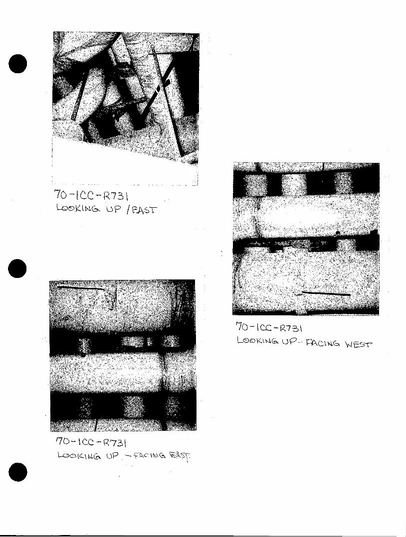
KKtG )P /plAST
'7c- IC-R73\
CO- t CC -73 lW&lcD Ca UP - vv< AT
ENCLOSURE 4
WATTS BAR NUCLEAR PLANT
NRC/TVA MEETING
U-BOLTS
ROCKVILLE, MID
OCTOBER 13, 1993
NRC MEETINGU-BOLTS
WATTS BAR NUCLEAR PLANT
* OPENING REMARKS MEDFORD
ISSUE DEFINITION MUSELER
* BACKGROUND WILLIAMS
* DISCUSSION OF KEY TECHNICAL ISSUES
SUMMARY AND CONCLUSIONS
WILLIAMS
ELLIOTT
I

0
ISSUE DEFINITION
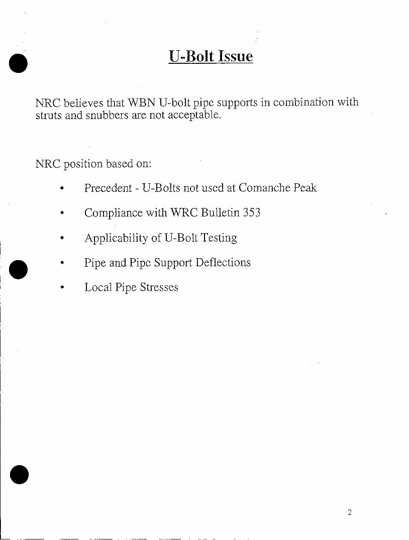
U-Bolt Issue
NRC believes that WBN U-bolt pipe supports in combination withstruts and snubbers are not acceptable.
NRC position based on:
* Precedent - U-Bolts not used at Comanche Peak
* Compliance with WRC Bulletin 353
* Applicability of U-Bolt Testing
* Pipe and Pipe Support Deflections
* Local Pipe Stresses

Precedent Issue
U-Bolts not approved at Comanche Peak.
TVA Response
* U-Bolt designs changed by Texas Utilities as aMgmt./Schedule decision.
* U-Bolt designs similar or identical to WBN designs existat eight plants (11 units) licensed since issue raised atComanche Peak.
* WBN U-Bolt designs meet Regulatory and Coderequirements.
* Based on the above, TVA considers the NRC position tobe a ratchet under 1OCFR50.109
3
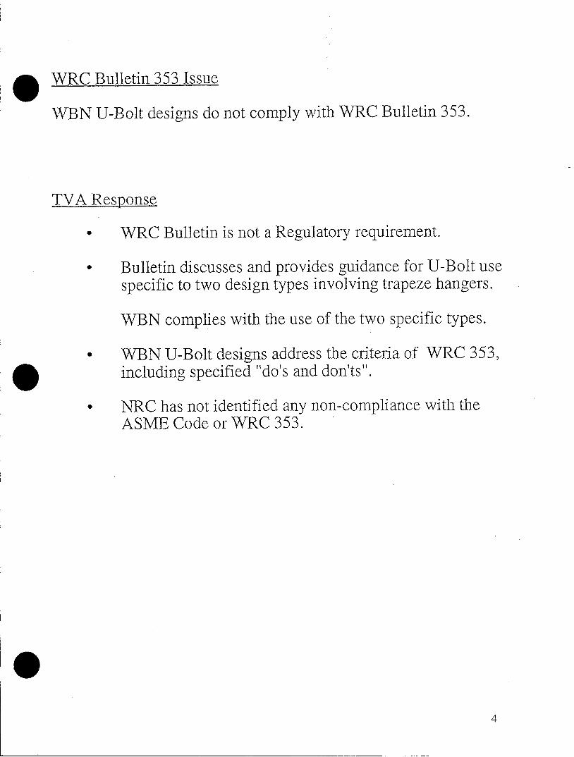
WRC Bulletin 353 Issue
WBN U-Bolt designs do not comply with WRC Bulletin 353.
TVA Response
* WRC Bulletin is not a Regulatory requirement.
* Bulletin discusses and provides guidance for U-Bolt usespecific to two design types involving trapeze hangers.
WBN complies with the use of the two specific types.
* WBN U-Bolt designs address the criteria of WRC 353,including specified "do's and don'ts".
* NRC has not identified any non-compliance with theASME Code or WRC 353.
4

BACKGROUND/TECHNICALDISCUS SIGN
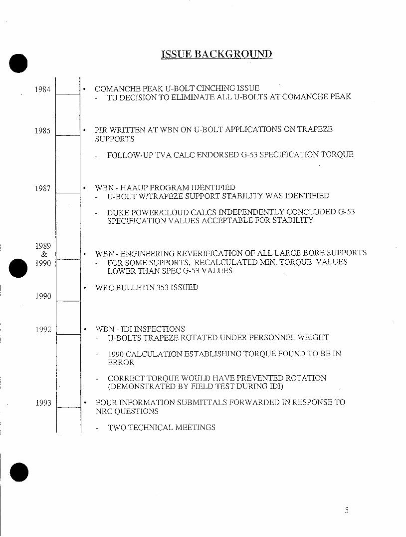
ISSUE BACKGROUND
1984 * COMANCHE PEAK U-BOLT CINCHING ISSUE- TU DECISION TO ELIMINATE ALL U-BOLTS AT COMANCHE PEAK
1985 * PIR WRITTEN AT WBN ON U-BOLT APPLICATIONS ON TRAPEZESUPPORTS
- FOLLOW-UP TVA CALC ENDORSED G-53 SPECIFICATION TORQUE
1987 * WBN - HAAUP PROGRAM IDENTIFIED- U-BOLT W/TRAPEZE SUPPORT STABILITY WAS IDENTIFIED
- DUKE POWER/CLOUD CALCS INDEPENDENTLY CONCLUDED G-53SPECIFICATION VALUES ACCEPTABLE FOR STABILITY
1989& * WBN - ENGINEERING REVERIFICATION OF ALL LARGE BORE SUPPORTS
1990 - FOR SOME SUPPORTS, RECALCULATED MIN. TORQUE VALUESLOWER THAN SPEC G-53 VALUES
* WRC BULLETIN 353 ISSUED1990
1992 * WBN - IDI INSPECTIONS- U-BOLTS TRAPEZE ROTATED UNDER PERSONNEL WEIGHT
- 1990 CALCULATION ESTABLISHING TORQUE FOUND TO BE INERROR
- CORRECT TORQUE WOULD HAVE PREVENTED ROTATION(DEMONSTRATED BY FIELD TEST DURING IDI)
1993 * FOUR INFORMATION SUBMITTALS FORWARDED IN RESPONSE TONRC QUESTIONS
- TWO TECHNICAL MEETINGS
5
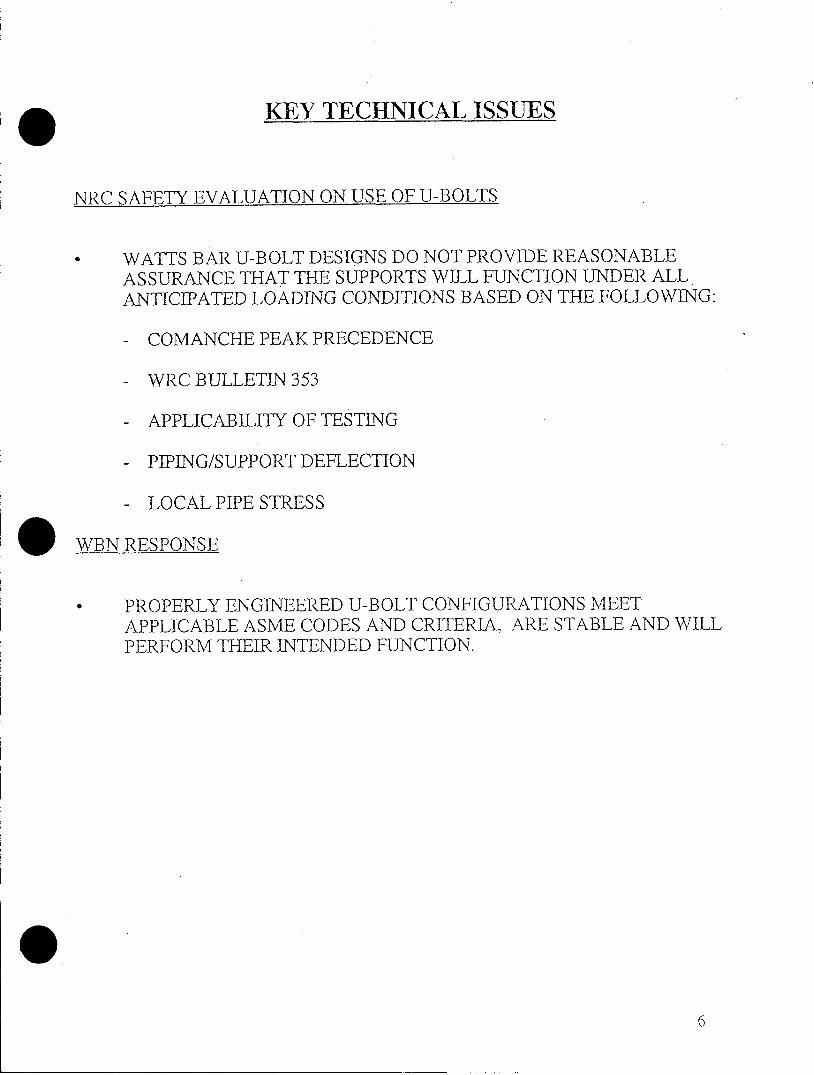
KEY TECHNICAL ISSUES
NRC SAFETY EVALUATION ON USE OF U-BOLTS
* WATTS BAR U-BOLT DESIGNS DO NOT PROVIDE REASONABLEASSURANCE THAT THE SUPPORTS WILL FUNCTION UNDER ALLANTICIPATED LOADING CONDITIONS BASED ON THE FOLLOWING:
- COMANCHE PEAK PRECEDENCE
- WRC BULLETIN 353
- APPLICABILITY OF TESTING
- PIPING/SUPPORT DEFLECTION
- LOCAL PIPE STRESS
WBN RESPONSE
* PROPERLY ENGINEERED U-BOLT CONFIGURATIONS MEETAPPLICABLE ASME CODES AND CRITERIA. ARE STABLE AND WILLPERFORM THEIR INTENDED FUNCTION.
6

COMANCHE PEAK PRECEDENCE
SER CONCERN
BECAUSE OF TECHNICAL CONCERNS . .. THE APPLICANT (TU) DECIDED
TO REPLACE ALL OF THESE DESIGNS AT COMANCHE PEAK.
WBN RESPONSE
TOTAL TU PROGRAM NOT COMPLETED NOR SUBMITTED FOR REVIEWBY STAFF.
WESTINGHOUSE PROGRAM CONCLUDED THAT PROPERLY ENGINEEREDU-BOLTS CAN PERFORM DESIGN FUNCTIONS.. TVA HAS REVIEWED W PROGRAM AND FOUND IT TO BE TECHNICALLYDEFENSIBLE AND APPLICABLE TO WBN.
WATTS BAR HAS SUPPLEMENTED AND ENHANCED PROGRAM BEGUN BYTU/WESTINGHOUSE/RLCA.
EIGHT PLANTS (11 UNITS) WITH SIMILAR CONFIGURATIONS HAVE BEENLICENSED SINCE COMANCHE PEAK ISSUE RAISED.
7

WRC BULLETIN 353
SER CONCERN
SECTION 2.4.5.3 TRAPEZE ASSEMBLES "TIGHT-FIT U-BOLTS ARE OFTENUSED IN SUPPORT ASSEMBLIES TO PROVIDE SUPPORT IN ONEDIRECTION FOR ROD HANGERS AND TWO DIRECTIONS FOR STRUTS ANDSNUBBERS. THE LATTER DESIGN IS NOT RECOMMENDED (REFER TOSECTION 2.4.1) FOR STABILITY REASONS."
WBN RESPONSE
CLARIFICATION OF WBN SUPPORTS
- ROD HANGERS ON SAFETY PIPING USED IN ONE DIRECTIONONLY.
- U-BOLTS WITH STRUTS OR SNUBBERS USED IN VERTICAL ORLATERAL DIRECTION ONLY.
- WRC 353. SECTION 2.4.5.3 CONTINUES WITH:
"IN THESE TYPE OF APPLICATIONS. THE U-BOLT IS PRIMARILYIN TENSION. THIS TYPE OF SUPPORT CAN BE USED FOR ALLSIZES OF PIPE. SEE FIGURES 6 AND 9."
* WBN PERFORMED INSITU TESTING TO VERIFY STABILITY
* WRC 353 PROVIDES SPECIFIC GUIDANCE FOR USE OF U-BOLTS
- WBN COMPLIES WITH DO'S AND DON'TS
8

VVBC BULLET/N
m
[J I I~I I I
(I- ------ --~
US-- O.- U-BOLT IN A R-ESTRAIUIT-TVYP
T R A p EZE -' A ER
w 1-Fm I m
; ' I
A \LTE LRNATE/ U SE O F U -BDOL IN A RE-STIRAT r.T111~IY?.
,D TR$APEZE i RANE
FIG r - -I G T F- -T
I/I
, I--
x -I F .0, D , c o -0 U I
7
-- I -
1, il l lI
-n-- J
I I I ,
I =
~: - ,~r~ - .,: w - -- *-~ ~- Z -* 7~,~11 '
9
353
,I,I -
1-f.
ml

APPLICABILITY OF TESTING
SER CONCERN WBN RESPONSE
ONE SEISMIC TEST PERFORMED -TEST WAS WORST CASE BASEDBY WESTINGHOUSE ON 10" SS PIPE HAVING HIGHEST
STRESSES BY EVALUATION
-SEISMIC ONLY ONE ASPECT OFSIGNIFICANT TESTING PROGRAM
U-BOLT SLID AXIALLY DURING W * U-BOLT MOVED AXIALLY BYSEISMIC TEST 1/2" MOVEMENT. INSIGNIFICANT
COMPARED TO OFFSETALLOWABLES
'10 TIMES DURATION AND TWOTIMES LOAD
RESTRAINT REMAINED STABLE
GLOBAL PIPE BENDING STRESS EFFECT ON BENDING STRESSESLEVEL IN W TEST NOT ARE ADDRESSED INDISCUSSED QUALIFICATION METHODS TO
ASME CODE
W TEST NOT DIRECTLY TESTING CONDUCTED ON POINTAPPLICABLE TO WBN DESIGNS CONTACT BETWEEN PIPE/CROSS-
MEMBER. SPECIFIC SUPPORTCONFIGURATIONS EVALUATEDCASE BY CASE
DIFFERENCES BETWEEN W TEST W REPORT RESULTS ARERESULTS AND FINITE ELEMENT CONSISTENT WITH TYPICALANALYSIS CAUSES THE TESTS TO COMPARISON BETWEEN TESTINGBE OF LIMITED USE AND ANALYSIS
W TEST PERFORMED WITHOUT NO EFFECT - LOADS CARRIED BYBELLEVILLE WASHER COLLARS IN AXIALASSEMBLIES COMPRESSION
e IN CONJUNCTION WITH THE WBN U-BOLT PROGRAM ELEMENTS,WESTINGHOUSE TESTING PROVIDES REASONABLE ASSURANCETHAT THE WBN DESIGNS WILL FUNCTION UNDER ALLANTICIPATED LOADING CONDITIONS
10

PIPING/SUPPORT DEFLECTION
SER CONCERN
STAFF QUESTIONED WHETHER DEFLECTION EXPERIENCED DURING THELOCAL PIPE STRESS EVALUATION AND/OR FLEXIBILITY OF WBN DESIGNEXCEEDED THE ALLOWABLE GLOBAL DEFLECTION LIMITS SPECIFIED IN THEFSAR.
WBN RESPONSE
* WBN FSAR CRITERIA LIMITS TO 1/8" GLOBAL SUPPORT DEFLECTION
* LOCAL PIPE DEFLECTION INDEPENDENT OF GLOBAL DEFLECTION
- INDUSTRY PRACTICE
- MEETS ASME CODE
_ _ _ _ _ _ _ _ _ _ _ _ _ _ _ _ _ _ _ _ _ _ _ -)'*I Ii
L CA,E D--C7-ECT-D,
AS:.: IR- l
, - - -.-
;=Ii
fl -'--
C ~ SJ~
11

LOCAL PIPE STRESSES
SER CONCERN
* TECHNICAL BASIS NOT PROVIDED TO DETERMINE ACCEPTABLE LOCALBEARING LOAD ON PIPE.
WBN RESPONSE
* MEETS REQUIREMENTS OF ASME CODE
- NC- 1100 PROVIDES FOR USE OF ALTERNATE METHODS WHERECOMPLETE DETAILS ARE NOT PROVIDED
- LOCAL U-BOLT BEARING LOAD EVALUATED UNDER NB-3228.1
* TO PROVIDE ASSURANCE OF LOCAL PIPE ACCEPTABILITY, THEFOLLOWING WERE PERFORMED:
- DETERMINE ALLOWABLE BEARING LOAD ON PIPE
- DEMONSTRATE APPLIED LOADING < ALLOWABLE LOCAL BEARINGLOAD
- SUPPORTS WHICH EXCEEDED ALLOWABLE LOCAL BEARING LOADWERE MODIFIED
CONCLUSION: LOCAL PIPE BEARING LOAD EVALUATION MEETS ASME CODEREQUIREMENTS, INCLUDES APPLICATIONS TO ALLCONFIGURATIONS AND IS CONSERVATIVE.
12
SUMMARY AND CONCLUSION

SUMMARY OF WBN APPROACH FOR U-BOLT UTILIZATION
AS A RESULT OF NRC ISSUES RAISED, WBN HAS INITIATED:
COMPLETE ENGINEERING PROGRAM
* CONSISTING OF TESTING, ANALYSIS, APPROPRIATE ACCEPTANCECRITERIA, DETAILED INSTALLATION PROCEDURE, INDIVIDUALLYANALYZED SUPPORTS
* TWELVE STATIC EQUIVALENT TESTS CONFIRMED TORQUEREQUIREMENTS AND INSTALLATION PROCEDURE
SUPPORT DESIGN IMPROVEMENTS
* ENGINEERED BELLEVILLE SPRING STACKS
* MODIFICATION OF SUPPORTS THAT DID NOT MEET DESIGNREQUIREMENTS
1 3
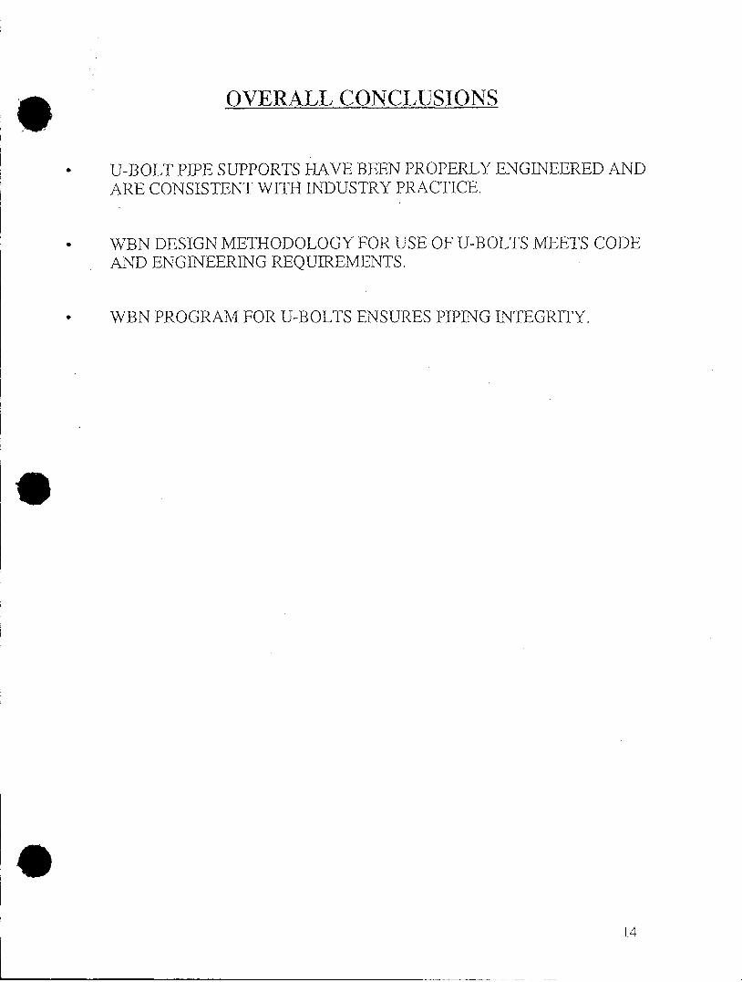
OVERALL CONCLUSIONS
* U-BOLT PIPE SUPPORTS HAVE BEEN PROPERLY ENGINEERED ANDARE CONSISTENT WITH INDUSTRY PRACTICE.
* WBN DESIGN METHODOLOGY FOR USE OF U-BOLTS MEETS CODEAND ENGINEERING REQUIREMENTS.
* WBN PROGRAM FOR U-BOLTS ENSURES PIPING INTEGRITY.
14