TENNANT T5 SCRUBBER DRYER OPERATOR MANUAL · TENNANT T5 SCRUBBER DRYER OPERATOR MANUAL Clemas & Co....
30
TENNANT T5 SCRUBBER DRYER OPERATOR MANUAL Clemas & Co. Unit 5 Ashchurch Business Centre, Alexandra Way, Tewkesbury, Gloucestershire, GL20 8NB. Tel: 01684 850777 Fax: 01684 850707 Email: [email protected] Web: www.clemas.co.uk
Transcript of TENNANT T5 SCRUBBER DRYER OPERATOR MANUAL · TENNANT T5 SCRUBBER DRYER OPERATOR MANUAL Clemas & Co....

TENNANT T5
SCRUBBER DRYER OPERATOR MANUAL
Clemas & Co. Unit 5 Ashchurch Business Centre, Alexandra Way, Tewkesbury, Gloucestershire, GL20 8NB.
Tel: 01684 850777 Fax: 01684 850707 Email: [email protected] Web: www.clemas.co.uk

OPERATION EN
Tennant T5 (06--06) 3
TABLE OF CONTENTS
SAFETY PRECAUTIONS 4. . . . . . . . . . . . . . . . . . . .
SAFETY LABELS 5. . . . . . . . . . . . . . . . . . . . . . . . . . .
MACHINE COMPONENTS 6. . . . . . . . . . . . . . . . . . .
CONTROL PANEL COMPONENTS 7. . . . . . . . . . .
MACHINE INSTALLATION 8. . . . . . . . . . . . . . . . . . .
UNCRATING MACHINE 8. . . . . . . . . . . . . . . . . .
INSTALLING BATTERIES 8. . . . . . . . . . . . . . . .
HOW THE MACHINE WORKS 9. . . . . . . . . . . . . . .
BRUSH AND PAD INFORMATION 9. . . . . . . . . . . .
MACHINE SETUP 9. . . . . . . . . . . . . . . . . . . . . . . . . .
ATTACHING SQUEEGEE ASSEMBLY 9. . . . .
INSTALLING BRUSHES/PADS 10. . . . . . . . . . . .
INSTALLING FAST--PAK CARTON 11. . . . . . . .
FILLING SOLUTION TANK 11. . . . . . . . . . . . . . .
MACHINE OPERATION 12. . . . . . . . . . . . . . . . . . . . .
PRE--OPERATION CHECKS 12. . . . . . . . . . . . . .
STARTING THE MACHINE 12. . . . . . . . . . . . . . .
EMERGENCY STOPPING 13. . . . . . . . . . . . . . . .
WHILE OPERATING MACHINE 13. . . . . . . . . . .
BATTERY CHARGE LEVEL INDICATOR 14. . .
HOUR METER 14. . . . . . . . . . . . . . . . . . . . . . . . . .
OFF--AISLE WAND OPERATION 14. . . . . . . . . .
DRAINING AND CLEANING TANKS 15. . . . . . . . . .
DRAINING RECOVERY TANK 15. . . . . . . . . . . .
DRAINING SOLUTION TANK 16. . . . . . . . . . . . .
CHARGING BATTERIES 16. . . . . . . . . . . . . . . . . . . .
BATTERY CHARGER SPECIFICATIONS 16. . .
ON--BOARD BATTERY CHARGER
SETTINGS 16. . . . . . . . . . . . . . . . . . . . . . . . . . . .
USING THE ON--BOARD BATTERY
CHARGER 17. . . . . . . . . . . . . . . . . . . . . . . . . . . .
ON--BOARD BATTERY CHARGER ERROR
CODES 18. . . . . . . . . . . . . . . . . . . . . . . . . . . . . . .
USING AN OFF--BOARD BATTERY
CHARGER 18. . . . . . . . . . . . . . . . . . . . . . . . . . . .
ADJUSTING SCRUB HEAD BRUSHES 19. . . . . . .
DISK MODEL 19. . . . . . . . . . . . . . . . . . . . . . . . . . .
CYLINDRICAL BRUSH MODEL 19. . . . . . . . . . .
MACHINE MAINTENANCE 21. . . . . . . . . . . . . . . . . .
DAILY MAINTENANCE 21. . . . . . . . . . . . . . . . . . .
MONTHLY MAINTENANCE 23. . . . . . . . . . . . . . .
BATTERY MAINTENANCE 24. . . . . . . . . . . . . . .
SQUEEGEE BLADES 24. . . . . . . . . . . . . . . . . . . .
MOTOR MAINTENANCE 25. . . . . . . . . . . . . . . . .
FAST SYSTEM MAINTENANCE 25. . . . . . . . . .
JACKING UP MACHINE 26. . . . . . . . . . . . . . . . . . . . .
TRANSPORTING MACHINE 26. . . . . . . . . . . . . . . . .
STORING MACHINE 26. . . . . . . . . . . . . . . . . . . . . . . .
RECOMMENDED STOCK ITEMS 26. . . . . . . . . . . . .
TROUBLESHOOTING 27. . . . . . . . . . . . . . . . . . . . . . .
CONTROL PANEL FAULT INDICATOR CODES 29
MACHINE SPECIFICATIONS 30. . . . . . . . . . . . . . . .

EN OPERATION
4 Tennant T5 (06--06)
SAFETY PRECAUTIONS
This machine is intended for industrial andcommercial use. It is designed exclusively to scrubhard floors in an indoor environment and is notconstructed for any other use. Only userecommended pads, brushes and commerciallyapproved floor cleaners intended for machineapplication.
The following warning alert symbol and the “FORSAFETY” heading are used throughout this manual asindicated in their description:
WARNING: To warn of hazards or unsafepractices which could result in severe personalinjury or death.
FOR SAFETY: To identify actions which must befollowed for safe operation of equipment.
The following safety precautions signal potentiallydangerous conditions to the operator orequipment. All operators must read, understandand practice them.
WARNING: Fire Or Explosion Hazard
-- Never Use Flammable Liquids Or OperateMachine In Or Near Flammable Liquids, VaporsOr Combustible Dusts.
This machine is not equipped with explosion proofmotors. The electric motors will spark upon startup and during operation which could cause a flashfire or explosion if machine is used in an areawhere flammable vapors/liquids or combustibledusts are present.
-- Do Not Pick Up Flammable Materials OrReactive Metals.
-- Batteries Emit Hydrogen Gas. Keep Sparks AndOpen Flame Away. Keep Battery CompartmentOpen When Charging.
WARNING: Electrical Hazard
-- Disconnect Battery Cables and Charger PlugBefore Servicing Machine.
-- Do Not Charge Batteries with Damaged PowerSupply Cord. Do Not Modify Plug.
If the charger supply cord is damaged or broken, itmust be replaced by the manufacturer or itsservice agent or a similarly qualified person inorder to avoid a hazard.
WARNING: Spinning Brush. Keep HandsAway. Turn Off Power Before Working On Machine.
FOR SAFETY:
1. Do not operate machine:
-- With flammable liquids or near flammablevapors as an explosion or flash fire mayoccur.
-- Unless trained and authorized.
-- Unless operator manual is read andunderstood.
-- If not in proper operating condition.
2. Before starting machine:
-- Make sure all safety devices are in placeand operate properly.
3. When using machine:
-- Go slow on inclines and slippery surfaces.
-- Wear non--slip shoes.
-- Reduce speed when turning.
-- Report machine damage or faulty operationimmediately.
-- Never allow children to play on or around.
-- Follow mixing and handling instructions onchemical containers.
-- Do not operate on inclines that exceed 5%(3°).
4. Before leaving or servicing machine:
-- Stop on level surface.
-- Turn off machine.
-- Set parking brake, if equipped.
-- Remove key.
5. When servicing machine:
-- Avoid moving parts. Do not wear loosejackets, shirts, or sleeves.
-- Disconnect battery cables and charger plugbefore working on machine.
-- Wear protective gloves and eye protectionwhen handling batteries or battery cables.
-- Avoid contact with battery acid.
-- Do not power spray or hose off machine.Electrical malfunction may occur.
-- Jack machine up at designated locationsonly (See JACKING UP MACHINE).
-- Use hoist or jack that will support machineweight.
-- Use manufacturer supplied or approvedreplacement parts.
-- All repairs must be performed by aqualified service person.
-- Do not modify the machine from its originaldesign.

OPERATION EN
Tennant T5 (06--06) 5
6. When loading/unloading machine onto/offtruck or trailer:
-- Drain tanks before loading.
-- Use a ramp that can support the machineweight and person loading it. Do notexceed a 11° ramp incline at a ramp lengthof 3.7m.
-- Turn machine off.
-- Put scrub head in the lowered position.
-- Block machine wheels.
-- Use tie--down straps to secure machine.
-- Set parking brake, if equipped.
SAFETY LABELS
The safety labels appear on the machine in the locations indicated. Replace labels if they are missing or becomedamaged or illegible.
SPINNING BRUSH LABEL --
Located on scrub head
WARNING: Spinning Brush.Keep Hands Away. Turn OffPower Before Working OnMachine.
READ MANUAL LABEL --Located on recovery tank cover.
FOR SAFETY: Do not operatemachine unless operationmanual is read and understood.
BATTERY CHARGE LABEL --Located at bottom side of recovery tank.
WARNING: Fire Or ExplosionHazard. Batteries Emit HydrogenGas. Keep Sparks And OpenFlame Away. Keep BatteryCompartment Open WhenCharging.

EN OPERATION
6 Tennant T5 (06--06)
MACHINE COMPONENTS
1
2
6
7
85
4
9
11
3
27
13
1415
16
18
1521
20
19
17
24
23
25
26
22
10
28
12
1. Control Handle2. Control Handle Start Bail3. Upper & Lower Control Panels4. Recovery Tank Drain Hose5. On--board Battery Charger6. Squeegee Lift Lever7. Rear Fill-Port8. Solution Tank Level/Drain Hose9. Squeegee Vacuum hose10. Wall Rollers11. Squeegee Assembly12. Solution Tank Clean-Out Port13. Recovery Tank Support Stand14. Control Board15. Bucket Fill Port/Clean--out Port16. FaST--PAK Carton Compartment17. Batteries18. Off--Aisle Wand Solution Hose Coupler19. Recovery Tank20. Recovery Tank Cover
21. Cup Holder22. Solution Tank23. Disk Scrub Head24. Pad Release Plunger25. Pad Driver Window26. Scrub Head Skirt27. Parking Brake28. Cylindrical Brush Scrub Head

OPERATION EN
Tennant T5 (06--06) 7
CONTROL PANEL COMPONENTS
5
6
10
11
12 14
13
2
3
1
4
7
98
1. Speed control knob2. 1--STEP scrub button3. Brush pressure increase button (+)4. Brush pressure decrease button (--)5. Solution flow increase button (+)6. Solution flow decrease button (--)7. Fault indicator -- Contact Service
8. Supervisor Control indicator -- Lockout feature9. Battery charge level indicator10. Emergency stop button11. Off--Aisle wand on/off switch (option)12. FaST system on/off switch (option)13. Main power on/off key switch14. Hour meter

EN OPERATION
8 Tennant T5 (06--06)
MACHINE INSTALLATION
UNCRATING MACHINE
1. Carefully check the shipping crate for signs ofdamage. Report damage at once to carrier.
2. Check the contents list. Contact distributor formissing items.
Contents:
S 4--6 V Batteries--Optional
S 3--Battery Cable Jumpers
S Battery Tray
S 1--FaST--PAK 365 Concentrate--Optional
S Squeegee Assembly
S 2--Pad drivers (Disk Model)
S 2--Brushes (Cylindrical Brush Model)
3. To uncrate your machine, remove the shippinghardware and straps that secure the machine tothe pallet. Carefully back machine down ramp.
ATTENTION: Do not roll machine off pallet unless aramp is used, machine damage may occur.
ATTENTION: To prevent possible machine damage,install batteries after removing machine fromshipping pallet.
INSTALLING BATTERIES
WARNING: Fire Or Explosion Hazard.Batteries Emit Hydrogen Gas. Keep Sparks AndOpen Flame Away. Keep Battery Hood Open WhenCharging.
FOR SAFETY: When installing batteries, wearprotective gloves and eye protection. Avoidcontact with battery acid.
Battery Specifications:Four 6 volt,180A/5h or 200A/5h deep cycle batteries.Maximum battery dimensions:190 mm W x 275 mm L x 284 mm H.
1. Park the machine on a level surface, remove thekey and set the parking brake.
2. Lift the recovery tank and remove the right sidebattery compartment panel (Figure 1). 13mmwrench required.
FIG. 1
3. Carefully install the batteries into the batterycompartment tray (Figure 2). Arrange the batteryposts as shown (Figure 3).
FIG. 2
4. Connect the battery cables to the battery posts asshown (Figure 3), RED TO POSITIVE (+) andBLACK TO NEGATIVE (--).
180A/5H200A/5H
MachineFront
RED
BLACK
FIG. 3
IMPORTANT: If your machine is equipped with theon--board battery charger, make sure that thecharger is properly set for your battery type beforecharging (See ON--BOARD CHARGER SETTINGS).
OPERATION EN
Tennant T5 (06--06) 9
HOW THE MACHINE WORKS
Conventional Scrubbing:Water and detergent from the solution tank flow to thefloor through a solution valve. The brushes use thedetergent and water to scrub the floor clean. As themachine moves forward, the squeegee wipes the dirtysolution from the floor into the recovery tank.
Foam Scrubbing (FaST Model):(FaST--Foam activated Scrubbing Technology)Unlike conventional scrubbing, the FaST system injectsthe FaST--PAK concentrate formula with a smallamount of water and air onto the floor. The mixturecreates a large volume of expanded wet foam for thebrush to scrub the floor clean. As the machine movesforward, the foam collapses and the squeegeerecovers the dirty solution into the the recovery tankleaving the floor clean dry and slip free.
BRUSH AND PAD INFORMATION
For best cleaning results use the appropriate brushtype for your cleaning application. Refer to the Partsmanual for part number information.
Polypropylene Bristle Scrub Brush (Black) --This general purpose polypropylene bristle scrub brushis used for scrubbing lightly compacted soilage. Thisbrush works well for maintaining concrete, wood andgrouted tile floors.
Soft Nylon Bristle Scrub Brush (White) --Recommended for cleaning coated floors withoutremoving finish. Cleans without scuffing.
Super Abrasive Bristle Scrub Brush (Gray) --Nylon fiber impregnated with abrasive grit to removestains and soilage. Strong action on any surface.Performs well on buildup, grease, or tire marks.
Polishing Pad (White) --Used to maintain highly polished or burnished floors.
Buffing Pad (Red) -- Used for light duty scrubbingwithout removing floor finish.
Scrubbing Pad (Blue) -- Used for medium toheavy--duty scrubbing. Removes dirt, spills, and scuffsand leaves surface clean ready for recoating.
Stripping Pad (Brown) -- Used for stripping of floorfinish to prepare the floor for recoating.
Heavy Duty Stripping Pad (Black) -- Used foraggressive stripping of heavy finishes/sealers, or veryheavy duty scrubbing.
MACHINE SETUP
ATTACHING SQUEEGEE ASSEMBLY
1. Park the machine on a level surface, remove thekey and set the parking brake if equipped.
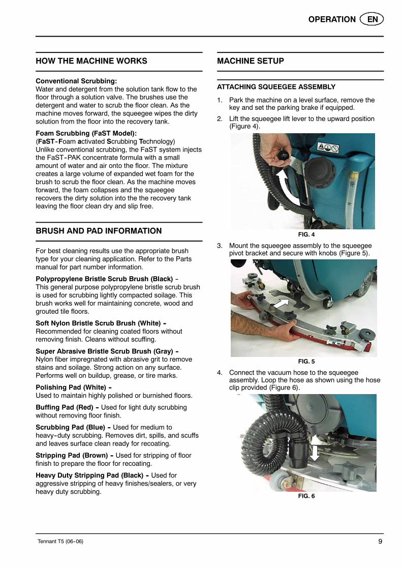
2. Lift the squeegee lift lever to the upward position(Figure 4).
FIG. 4
3. Mount the squeegee assembly to the squeegeepivot bracket and secure with knobs (Figure 5).
FIG. 5
4. Connect the vacuum hose to the squeegeeassembly. Loop the hose as shown using the hoseclip provided (Figure 6).
FIG. 6

EN OPERATION
10 Tennant T5 (06--06)
5. Check the squeegee blades for proper deflection.The blades should deflect as shown (Figure 7).
FIG. 7
6. To adjust the blade deflection, place the squeegeeassembly on a level surface and adjust the castersas shown (Figure 8).
2 mm
Lock Nut
FIG. 8
INSTALLING BRUSHES/PADS
FOR SAFETY: Before installing brushes, stopmachine on level surface, remove key and setparking brake if equipped.
Disk Model:
1. Raise scrub head off the floor and remove key.
2. Attach the pad to the pad driver before installingthe driver. Secure pad with centerlock (Figure 9).
FIG. 9
3. Align the pad driver under the motor hub and pushit upward to engage (Figure 10).
FIG. 10
4. To remove the pad driver, raise the scrub head andpush the pad release plunger downward(Figure 11).
FIG. 11
5. Check the scrub head to ensure that it is properlyadjusted (See ADJUSTING SCRUB HEADBRUSHES).
Cylindrical Brush Model:
1. Raise scrub head off the floor and remove key.
2. Remove idler plate from scrub head by pressingthe spring tab downward (Figure 12).
FIG. 12
3. Attach idler plate to the brush end that has thedouble row of bristles (Figure 13). Install brush.

OPERATION EN
Tennant T5 (06--06) 11
Double row ofbristles
FIG. 13
4. Check the brushes to ensure they are properlyadjusted (See ADJUSTING SCRUB HEADBRUSHES).
INSTALLING FaST--PAK CARTON (FaST Model)
ATTENTION: The FaST--PAK Concentrate Formulais specifically designed for the FaST system.NEVER use a substitute. Machine damage mayresult.
1. Pull out the hose connector from the FaST--PAKcarton and remove cap (Figure 14).
FIG. 14
2. Open the battery compartment. Connect theFaST--PAK carton to the supply hose and placecarton in compartment (Figure 15). Make sure thehose does not get pinched.
FIG. 15
3. When the supply hose is not in use, connect thestorage plug to prevent the FaST system fromdrying out and clogging up the hose. (Figure 16).
FIG. 16
FILLING SOLUTION TANK
Using a hose or bucket, fill the solution tank to the“MAX 85L” mark (Figure 17).
For FaST Scrubbing: Use cool clean water only (lessthan 21°C). Do not add any conventional floor cleaningdetergents, FaST system failure may result.
For Conventional Scrubbing: Use hot water (60°Cmaximum). Pour a recommended cleaning detergentinto the solution tank according to mixing instructionson the container.
FIG. 17
ATTENTION: For conventional scrubbing, only usecommercially approved cleaning detergents.Machine damage due to improper detergent usagewill void the manufacturer’s warranty.
WARNING: Fire or Explosion Hazard.Never Use Flammable Liquids.

EN OPERATION
12 Tennant T5 (06--06)
MACHINE OPERATION
FOR SAFETY: Do not operate machine, unlessoperator manual is read and understood.
WARNING: Fire Or Explosion Hazard. NeverOperate Machine In Or Near Flammable Liquids,Vapors Or Combustible Dusts.
PRE--OPERATION CHECKS
- Sweep area.
- Check the battery charge level indicator.
- Check the brushes/pads for wear.
- Check the squeegee blades for wear and properadjustment.
- Make sure the recovery tank is empty and the floatshut--off screen is installed and clean.
- Check the scrub head skirt for wear.
- Foam Scrubbing (FaST model): Check theFaST--PAK concentrate level.
- Foam Scrubbing (FaST model): Make sure thesolution tank is filled with cool clean water only.
- Foam Scrubbing (FaST model): Ensure that allconventional cleaning agents are drained andrinsed from solution tank.
STARTING THE MACHINE
1. Release the parking brake if equipped (Figure 18).
2. Turn the key to the on ( I ) position (Figure 18).
FIG. 18
3. To foam scrub (FaST model), press the FaSTsystem switch to the on ( I ) position (Figure 19).
IMPORTANT: NEVER turn the FaST system switch onwhen conventional scrubbing. Conventional cleaningdetergents/restorers may cause failure to the FaSTinjection system. Drain, rinse and refill solution tankwith cool clean water before operating the FaSTsystem.
FIG. 19
4. Lower the squeegee assembly to floor by loweringthe squeegee lift lever (Figure 20).
FIG. 20
5. Press the 1--STEP scrub button (Figure 21).
FIG. 21
6. Pull the control handle bail to start scrubbing(Figure 22). To reverse the machine, simply pushthe control handle bail forward. Raise squeegeewhen reversing machine.

OPERATION EN
Tennant T5 (06--06) 13
FIG. 22
7. Adjust the speed control knob to a desiredscrubbing speed (Figure 23).
NOTE: 45--60 meters per minute is the recommendedscrubbing speed.
FIG. 23
8. Press the brush pressure and solution flow buttonsto increase (+) or decrease (--) as needed (Figure24). To shut off the solution flow, continue to pressthe decrease button (--) until the lights turn off.
NOTE: When foam scrubbing (FaST), the solution flowlights will not light up. The FaST system solution flowrate is fixed and requires no adjustment.
FIG. 24
9. To stop scrubbing, release the control handle bail,press the 1--STEP scrub button and raise thesqueegee.
EMERGENCY STOPPING
Strike the emergency stop button, if equipped, in theevent of an emergency (Figure 25). This button shutsoff all power to machine. Turn the button clockwise andrestart the key to regain power.
FIG. 25
WHILE OPERATING MACHINE
WARNING: Fire Or Explosion Hazard. Do NotPick Up Flammable Materials Or Reactive Metals.
1. Overlap each scrub path by 5 cm.
2. Keep the machine moving to prevent damage tofloor finish.
3. Do not operate the machine on inclines that exceed
5% (3°).
4. Conventional scrubbing: Pour a commerciallyapproved foam control solution into the recoverytank if excessive foam appears.
ATTENTION: Do not allow foam to enter the floatshut-off screen, vacuum motor damage will result.Foam will not activate the float shut-off screen.
5. For heavily soiled areas, use the double scrubbingmethod. First scrub the area with the squeegee up,let solution set for 3--5 minutes, then scrub the areaa second time with squeegee down.
6. When leaving the machine unattended, remove thekey and set the parking brake, if equipped.
7. If the machine detects a fault, the control panellights will blink a fault code (See CONTROLPANEL FAULT INDICATOR CODES).

EN OPERATION
14 Tennant T5 (06--06)
BATTERY CHARGE LEVEL INDICATOR
The battery charge level indicator displays the chargelevel of the batteries (Figure 26). When the batteriesare fully charged, all five indicator lights will glow. Asthe batteries discharge, the indicator lights will begin togo out from right to left.
When the discharge level reaches the red light, theoperator will have approximately one minute tocontinue scrubbing. When the red light begins to flashthe scrubbing functions will automatically shut off toalert the operator to recharge the batteries. By pressingthe 1--STEP Scrub button, when the red light isflashing, the operator will get an additional minute ofscrubbing.
FIG. 26
HOUR METER
The hour meter records the number of total hours thevacuum and brush motors have been powered on. Usethe hour meter to determine when to performrecommended maintenance procedures and to recordservice history (Figure 27). See MOTORMAINTENANCE.
FIG. 27
OFF--AISLE WAND SETUP AND OPERATION
If your machine is equipped with the off--aisle wandoption, this allows you to scrub areas where themachine is unable to reach.
Preparing Machine for Off--Aisle Wand Scrubbing:
1. Park the machine on a level surface, turn key offand set parking brake if equipped.
2. Connect the solution hose to the coupler at thelower right side of machine (Figure 28).
FIG. 28
3. Using the hose adapter, connect the squeegeehose to the wand hose (Figure 29).
FIG. 29
4. Attach the off--aisle wand to the hoses (Figure 30).
FIG. 30

OPERATION EN
Tennant T5 (06--06) 15
Operating the Off--Aisle Wand:
1. Turn the key and wand switch to the on ( I )position (Figure 31). The FaST system switch isdisabled when operating the wand.
FIG. 31
2. Lower the squeegee to activate the vacuum motor(Figure 32).
FIG. 32
3. Squeeze trigger to activate solution. Use brush forscrubbing and squeegee for pickup (Figure 33).
FIG. 33
4. After scrubbing, turn off the wand switch andsqueeze the trigger for five seconds to relieve thewater pressure before disconnecting the solutionhose.
WARNING: Fire or Explosion Hazard. Do NotPick Up Flammable Materials Or Reactive Metals.
DRAINING AND CLEANING TANKS
After each use, the tanks should be drained and cleaned.
DRAINING RECOVERY TANK
1. Transport machine to disposal area and turn keyswitch off.
2. While holding the drain hose upward, remove thecap and lower hose to drain (Figure 34).
FIG. 34
3. After draining, open the recovery tank and cleanout the tank (Figure 35).
FIG. 35
4. Clean the float shut-off screen and debris traylocated in the recovery tank (Figure 36).
FIG. 36

EN OPERATION
16 Tennant T5 (06--06)
DRAINING SOLUTION TANK
1. To drain remaining water from the solution tank,pull the solution tank level hose off the hose fitting(Figure 37).
FIG. 37
2. To rinse out the solution tank remove the clean--outcap at the rear of the machine and spray waterdirectly into the clean-out ports (Figure 38).
FIG. 38
3. Clean the solution tank filter (Figure 39).
FIG. 39
CHARGING BATTERIES
ATTENTION: To prolong the life of the batteriesonly recharge the batteries if the machine wasused for a total of 30 minutes or more. Do not leavebatteries discharged for lengthy periods.
WARNING: Fire Or Explosion Hazard.Batteries Emit Hydrogen Gas. Keep Sparks AndOpen Flame Away. Keep Battery CompartmentOpen When Charging.
FOR SAFETY: When servicing batteries, wearprotective gloves and eye protection whenhandling batteries and battery cables. Avoidcontact with battery acid.
BATTERY CHARGER SPECIFICATIONS:
S CHARGER TYPE:-- FOR SEALED (Gel) BATTERIES-- FOR WET (Lead acid) BATTERIES
S OUTPUT VOLTAGE - 24 VOLTS
S OUTPUT CURRENT - 20 AMPS
S AUTOMATIC SHUTOFF CIRCUIT
S FOR DEEP CYCLE BATTERY CHARGING
ON--BOARD BATTERY CHARGER SETTINGS:
If your machine is equipped with the on--board charger,the charger settings must be set for your battery type,Wet/lead acid or sealed/Gel, before charging. Failure toproperly set will result in battery damage.
To determine your battery type, see battery label.Contact your battery supplier if not specified.
To verify what the charger is currently for, connect thecharger cord into an electrical receptacle. The chargerwill display a sequence of codes. One of the codes willeither read “GEL” or “Acd” (Figure 40).
GEL = Set for sealed/maintenance free batteriesAcd = Set for wet/lead acid batteries
FIG. 40

OPERATION EN
Tennant T5 (09--06) 17
To change the setting, unplug the charger, peel up thecorner of the display label and set the switchesaccordingly (Fig. 41). The charger cord must beunplugged when resetting.
WET “Acd” BATTERYSEALED “GEL” BATTERY
FIG. 41
USING THE ON--BOARD BATTERY CHARGER
IMPORTANT: Before charging, make sure that thecharger setting is properly set for your battery type(See ON--BOARD CHARGER SETTINGS).
1. Transport the machine to a well--ventilated area.
2. Park the machine on a flat, dry surface. Turn thekey off and set the parking brake, if equipped.
3. If charging wet (lead acid) batteries check the fluidlevel before charging (See BATTERYMAINTENANCE).
4. Prop up the recovery tank for ventilation(Figure 42).
FIG. 42
5. Connect the charger’s AC power supply cord into aproperly grounded receptacle (Figure 43).
NOTE: The machine will not operate when charging.
FIG. 43
6. The charger will display a sequence of codes oncethe cord is connected (Figure 44).
Three--digits + the following code:
A = Charging current
U = Battery Voltage
h = Charging time
C = Charging ampere--hours [Ah]
E = Energy used [Kwh]
“GEL” or “Acd” = Battery type the charger iscurrently set for. Before charging make sureyour battery type matches the display:GEL=Sealed, Acd=WET (lead acid). To changesetting, see ON--BOARD CHARGERSETTINGS.
Press the arrow button to review the codes.
FIG. 44
7. Once the charging cycle begins, the indicator lightswill progress from red, yellow to green. When thegreen indicator light comes on, the charging cycleis done. Unplug the charger cord.
If the charger detects a problem, the charger willdisplay an error code (See ON--BOARD BATTERYCHARGER ERROR CODES).

EN OPERATION
18 Tennant T5 (06--06)
ON--BOARD BATTERY CHARGER ERROR CODES
DISPLAY CODE FAULT SOLUTION
bat Loose or damaged battery cable Check battery cable connections.
Battery exceeded maximum voltage level. No action necessary.
E01 Exceeded maximum battery voltage allowed. No action necessary.
E02 Safety thermostat exceeded maximuminternal temperature.
Check if the charger vents are obstructed.
E03 Exceeded maximum time for charging phaseleaving the batteries undercharged due to asulfated or faulty battery.
Repeat the charging cycle and if the errorcode E03 reappears check battery orreplace it.
SCt Safety timer exceeded maximum chargingtime. Interrupts charging cycle.
Replace battery.
Srt Possible internal short circuit. Contact Service Center.
USING AN OFF--BOARD BATTERY CHARGER(OPTION)
1. Transport the machine to a well--ventilated area.
2. Park the machine on a flat, dry surface. Turn thekey off and set the parking brake, if equipped.
3. If charging wet (lead acid) batteries, check the fluidlevel before charging (See BATTERYMAINTENANCE).
4. Prop up the recovery tank for ventilation(Figure 45).
FIG. 45
5. Connect the charger’s AC power supply cord into aproperly grounded receptacle.
6. Connect the charger’s DC cord into the machine’sbattery receptacle (Figure 46).
FIG. 46
7. The supplied charger will automatically begincharging and shut off when fully charged.
NOTE: The machine will not operate when charging.
ATTENTION: Do not disconnect the charger’s DCcord from the machine’s receptacle when thecharger is operating. Arcing may result. If thecharger must be interrupted during charging,disconnect the AC power supply cord first.
OPERATION EN
Tennant T5 (06--06) 19
ADJUSTING SCRUB HEAD BRUSHES
To ensure optimum scrubbing performance periodicallycheck the scrub head for proper adjustment.
FOR SAFETY: Before adjusting scrub head, stopmachine on level surface, remove key and setparking brake if equipped.
DISK MODEL
Tools required: Measuring device, 27mm wrench and24mm wrench
1. With brushes installed, lower the scrub head andapply medium brush pressure.
2. Turn machine off and remove key.
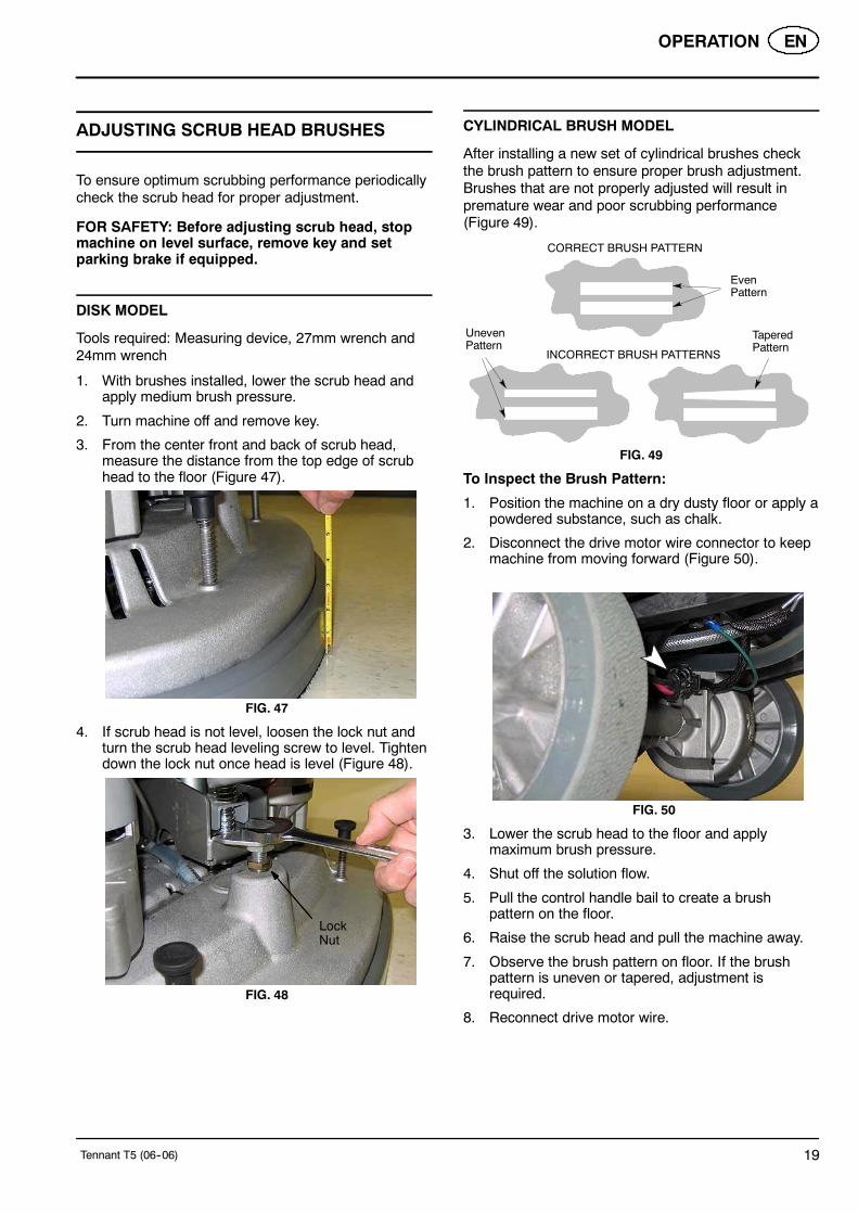
3. From the center front and back of scrub head,measure the distance from the top edge of scrubhead to the floor (Figure 47).
FIG. 47
4. If scrub head is not level, loosen the lock nut andturn the scrub head leveling screw to level. Tightendown the lock nut once head is level (Figure 48).
LockNut
FIG. 48
CYLINDRICAL BRUSH MODEL
After installing a new set of cylindrical brushes checkthe brush pattern to ensure proper brush adjustment.Brushes that are not properly adjusted will result inpremature wear and poor scrubbing performance(Figure 49).
CORRECT BRUSH PATTERN
INCORRECT BRUSH PATTERNS
EvenPattern
TaperedPattern
UnevenPattern
FIG. 49
To Inspect the Brush Pattern:
1. Position the machine on a dry dusty floor or apply apowdered substance, such as chalk.
2. Disconnect the drive motor wire connector to keepmachine from moving forward (Figure 50).
FIG. 50
3. Lower the scrub head to the floor and applymaximum brush pressure.
4. Shut off the solution flow.
5. Pull the control handle bail to create a brushpattern on the floor.
6. Raise the scrub head and pull the machine away.
7. Observe the brush pattern on floor. If the brushpattern is uneven or tapered, adjustment isrequired.
8. Reconnect drive motor wire.

EN OPERATION
20 Tennant T5 (06--06)
To Adjust an Uneven Brush Pattern:
Tools required: Measuring device, 27mm wrench and24mm wrench
1. Measure the distance from the front edge of thescrub head to the floor and from the back edge ofthe scrub head to the floor (Figure 51). Themeasurements should be the same.
FIG. 51
2. To level the scrub head, loosen the lock nut andturn the leveling screw clockwise to lower the rearof the scrub head or counter--clockwise to lower thefront (Figure 52).
FIG. 52
3. Recheck brush pattern.
NOTE: Replace brushes when worn to 15mm.
To Adjust a Tapered Brush Pattern:
Tools required: 10mm wrench and 6mm hex wrench
1. Raise the scrub head off floor and remove key.
2. Remove the idler plate from the brush (Figure 53).
FIG. 53
3. Hold the brush plug shaft with a wrench and loosenthe 6mm hex screw (Figure 54).
FIG. 54
4. To lower the brush end, turn the shaft clockwise forthe front brush and counter--clockwise for the rearbrush. Retighten hex screw (Figure 55).
FIG. 55
5. Recheck brush pattern.
NOTE: Replace brushes when worn to 15mm.

OPERATION EN
Tennant T5 (06--06) 21
MACHINE MAINTENANCE
To keep the machine in good working condition, it’simportant that the following maintenance proceduresare performed on a routine basis.
WARNING: Electrical Hazard. DisconnectBattery Cables Before Servicing Machine.
DAILY MAINTENANCE (After Every Use)
1. Drain the recovery tank (Figure 56).
FIG. 56
2. Rinse and clean out the recovery tank (Figure 57).
FIG. 57
3. Remove the recovery tank float shut--off screenand clean (Figure 58).
FIG. 58
4. Remove the debris tray and empty (Figure 59)
FIG. 59
5. Drain the solution tank (Figure 60).
FIG. 60
6 Clean the solution tank filter (Figure 61).
FIG. 61
7. Rotate pad or replace when worn (Figure 62).
Disk Model
FIG. 62

EN OPERATION
22 Tennant T5 (06--06)
8. Empty and rinse out the debris trough (Figure 63).
Cylindrical Brush Model
FIG. 63
9. Inspect the cylindrical brushes for wear. Rotatebrushes from front--to--rear every 50 hours (Figure64). Replace when worn to a length of 15mm.
15mm
CylindricalBrush Model
FIG. 64
10. Remove debris buildup from the underside of thecylindrical brush scrub head, including the idlerplates and drive hubs (Figure 65).
Cylindrical Brush Model
FIG. 65
11. Wipe the squeegee blades clean (Figure 66). Storethe squeegee assembly in the raised position toprevent blade damage.
FIG. 66
12. Check the condition of the squeegee blade wipingedge (Figure 67). Rotate blade if worn (SeeSQUEEGEE BLADES).
FIG. 67
13. Clean the machine with an all purpose cleaner anddamp cloth (Figure 68).
FOR SAFETY: When cleaning machine, do notpower spray or hose off machine. Electricalmalfunction may occur.
FIG. 68

OPERATION EN
Tennant T5 (06--06) 23
14. Inspect the condition of the scrub head skirt,replace if worn or damaged (Figure 69).
Cylindrical Brush Model
FIG. 69
15. FaST Model: Connect the FaST--PAK supply hoseto the storage plug when not in use (Figure 70).Remove any dried concentrate from the hoseconnector by soaking it in warm water.
FIG. 70
16. Clean wet/lead acid batteries to prevent corrosionand check for loose battery cable connections (SeeBATTERY MAINTENANCE).
17. Recharge the batteries (Figure 71). To prolong thelife of the batteries, only recharge the batteries ifthe machine was used for a total of 30 minutes ormore.
FIG. 71
MONTHLY MAINTENANCE
1. Check the cylindrical brush belt tension every 100hours (Figure 72). Belt tension should flex 3mm atmidpoint, with 1.13--1.22 Kg force.
WARNING: Electrical Hazard. DisconnectBattery Cables Before Servicing Machine.
Cylindrical Brush Model
FIG. 72
2. Inspect and clean the recovery tank cover seal(Figure 73). Replace if damaged.
FIG. 73
3. Lubricate all pivot points and rollers with a waterresistant grease.
4. Lubricate the casters with a water resistant grease(Figure 74).
FIG. 74

EN OPERATION
24 Tennant T5 (06--06)
5. Clean the parking brake clamp with a cleaningsolvent.
6. Check the machine for loose nuts and bolts.
7. Check the machine for leaks.
BATTERY MAINTENANCE (Wet/lead acid batteries)
1. Check battery fluid level frequently to preventbattery damage. The fluid should be at the levelshown (Figure 75). Add distilled water if low. DONOT OVERFILL, the fluid may expand andoverflow when charging.
Before Charging After Charging
CORRECT BATTERY FLUID LEVEL:
FIG. 75
WARNING: Fire Or Explosion Hazard.Batteries Emit Hydrogen Gas. Keep Sparks AndOpen Flame Away. Keep Battery CompartmentOpen When Charging.
2. Clean the batteries to prevent battery corrosion.Use a scrub brush with a mixture of baking sodaand water (Figure 76).
FOR SAFETY: When cleaning batteries, wearprotective gloves and eye protection. Avoidcontact with battery acid.
FIG. 76
SQUEEGEE BLADES
When the blades become worn, simply rotate theblades end-for-end or top-to-bottom to a new wipingedge. Replace blades when all edges are worn.
The front blades on the 700mm/800mm squeegeeassemblies have 12/14 slots on one edge and 6 slotson the opposite edge (Figure 77). If making sharp turnswith the cylindrical brush models use the 12/14 slottededge for maximum water pickup.
6 Slots on oneedge
12/14 Slots onopposite edge
FIG. 77
Replacing Squeegee Blades:
1. Loosen the band clamp and remove the band fromthe squeegee assembly (Figure 78).
FIG. 78

OPERATION EN
Tennant T5 (06--06) 25
2. Replace or rotate the rear blade to a new wipingedge and replace band (Figure 79).
FIG. 79
3. To change the front blade, remove the band andloosen the four knobs. Replace or rotate the frontblade to a new wiping edge (Figure 80).
FIG. 80
MOTOR MAINTENANCE
Contact an Authorized Tennant Service Center forcarbon brush replacement.
Carbon Brush Replacement Hours
Drive Transaxle Motor
750Vacuum Motor
Disk Brush Motors
Cylindrical Brush Motors 1000
WARNING: Electrical Hazard. DisconnectBattery Cables Before Servicing Machine.
FaST SYSTEM MAINTENANCE
Every 1000 hours replace the orifice plate and filterscreen located inside the detergent injector assembly.Order service kit p/n 9001489.
1. To access the detergent injector assembly, lowerthe scrub head and remove the front shroud(Figure 81)
FIG. 81
2. Remove the injector assembly from clamps(Figure 82).
FIG. 82
3 Unthread the black plastic filter housing and replacethe orifice plate and filter (Figure 83).
FIG. 83

EN OPERATION
26 Tennant T5 (06--06)
JACKING UP MACHINE
Use the designated locations to jack up the machine forservice (Figure 84). Empty the recovery and solutiontank and position the machine on a level before jacking.
FOR SAFETY: When servicing machine, jackmachine up at designated locations only. Use jackor hoist that will support machine weight.
FIG. 84
TRANSPORTING MACHINE
When transporting the machine by trailer or truck, becertain to follow the transporting procedure below:
1. Drain machine tanks.
2. Load the machine using a ramp that can supportthe machine weight and person loading it. Themaximum ramp incline should not exceed 11° at aramp length of 3.7m.
3. Position the front of machine up against the front ofthe trailer or truck. Lower the scrub head andsqueegee.
4. Set the parking brake, if equipped, and place ablock behind each wheel to prevent the machinefrom rolling.
5. Secure with tie--down straps as shown (Figure 85).It may be necessary to install tie-down brackets totrailer or truck.
FOR SAFETY: When loading/unloading machineonto/off truck or trailer, use a ramp that cansupport the machine weight and person loading it,do not exceed a 11° ramp incline at a ramp lengthof 3.7m, use tie--down straps to secure machineand block machine wheels.
FIG. 85
STORING MACHINE
1. Charge the batteries before storing machine toprolong the life of the batteries.
2. Drain and rinse the tanks thoroughly.
3. Store the machine in a dry area with the squeegeeand scrub head in the up position.
4. Open the recovery tank cover to promote aircirculation.
ATTENTION: Do not expose machine to rain, storeindoors.
5. If storing machine in freezing temperatures, makesure to drain machine of all water.
RECOMMENDED STOCK ITEMS
Refer to the Parts List Manual for recommended stockitems. Stock Items are clearly identified with a bulletpreceding the parts description. See example below:

OPERATION EN
Tennant T5 (06--06) 27
TROUBLESHOOTING
PROBLEM CAUSE SOLUTION
Machine will not operate Discharged batteries Charge batteries
Emergency--stop button activated Turn button clockwise to reset
Faulty battery(s) Replace battery(s)
Loose battery cable Tighten loose cable
Faulty control board Contact Service Center
Faulty key switch Contact Service Center
Machine fault detected. See Contol Panel Fault IndicatorCodes
Onboard battery charger will notoperate
Plug not connected to power supply Check plug connection
Faulty charger fuse Replace charger fuse
Faulty power supply cord Replace cord
Error detected. See On--board Battery Charger ErrorCodes
Brush motor(s) will not operate 1--STEP scrub button is off Turn on the 1--STEP scrub button
Brush motor overload See Control Panel Fault IndicatorCodes
Discharged batteries Charge batteries
Faulty control board Contact Service Center
Faulty scrub head (up/down) switch Contact Service Center
Faulty control handle bail switch Contact Service Center
Faulty brush motor or wiring Contact Service Center
Worn carbon brushes Contact Service Center
Broken or loose belt(cylindrical brush model)
Replace or tighten belt
Machine will not propel Parking brake is set Release parking brake lever
Machine fault detected See Control Panel Fault IndicatorCodes
Faulty control board Contact Service Center
Wheels raised off floor Contact Service Center
Faulty transaxle motor or wiring Contact Service Center
Worn carbon brushes Contact Service Center
Exceeded maximum incline Avoid steep inclines and reset key
Vacuum motor will not operate Squeegee is raised off floor Lower squeegee
Discharged batteries Charge batteries
Faulty control board Contact Service Center
Faulty vacuum motor or wiring Contact Service Center
Worn carbon brushes Contact Service Center
Little or no solution flow Solution tank is empty Fill solution tank
Clogged solution tank filter Clean solution tank filter
Discharged batteries Charge batteries
Clogged solution valve Remove valve and clean
Faulty control board Contact Service Center

EN OPERATION
28 Tennant T5 (06--06)
TROUBLESHOOTING -- Continued
PROBLEM CAUSE SOLUTION
Poor water pickup Recovery tank is full or excessivefoam buildup
Drain recovery tank
Loose drain hose cap Tighten cap
Clogged float shut--off screen locatedin recovery tank
Clean screen
Clogged squeegee assembly Clean squeegee assembly
Worn squeegee blades Replace or rotate squeegee blades
Incorrect Squeegee blade deflection Adjust Squeegee blade height
Loose vacuum hose connections Secure hose connections
Clogged vacuum hose Remove clogged debris
Damaged vacuum hose Replace vacuum hose
Recovery tank cover not in place Properly position cover
Damaged recovery tank cover seal Replace seal
Faulty vacuum motor Contact Service Center
Poor scrubbing performance Debris caught in brush Remove debris
Worn brushes/pads Replace brushes/pads
Incorrect brush pressure setting Adjust pressure setting
Wrong brush/pad type. Use correct brush/pad
Reduced run time Batteries not fully charged Fully recharge batteries
Defective batteries Replace battery
Batteries need maintenance See BATTERY MAINTENANCE
Faulty battery charger Repair or replace battery charger
Solution flow and brush pressurebuttons and FaST system switchare locked
Supervisor controls are activated(lockout feature)
Contact your Supervisor
FaST Model: FaST System doesnot operate or operate correctly
FaST system switch is not turned on Turn on FaST system switch
FaST--PAK supply hose not connected Connect supply hose
Clogged FaST--PAK supply hose orconnectors
Soak in warm water to unclog
Empty FaST--PAK carton Replace FaST--PAK carton
Kink in FaST--PAK supply hose Undo hose kink
Clogged FaST solution system Contact Service Center
Faulty FaST system on/off switch Contact Service Center
Faulty pump Contact Service Center
Clogged solution tank filter Drain solution tank. remove solutiontank filter, clean and reinstall
Clogged detergent orifice/filter screen Replace orifice/filter screen(See FaST SYSTEMMAINTENANCE)
Clogged FaST solution inlet filter Contact Service Center
Faulty control board Contact Service Center

OPERATION EN
Tennant T5 (06--06) 29
CONTROL PANEL FAULT INDICATOR CODES
The control panel fault indicator lights will display the following codes when the machine detects a fault.
Light #1 Light #2 Light #3
Light #4
Battery Lights
CODE FAULT SOLUTION
Light #1 blinks Recovery tank is raised. Lower recovery tank. Restart key to reset.
Lights #1, #2 and #3ripple
Battery charger connected. Disconnect battery charger. Restart key toreset.
Lights #1 and #4 blink Left Brush motor overload. Inspect brush for entangled debris,improper pad or contact service center.Restart key to reset.
Lights #3 and #4 blink Right Brush motor overload. Inspect brush for entangled debris,improper pad or contact service center.Restart key to reset.
Lights #2 and #3 blink Propel motor overload.Exceeded maximum incline.
Avoid steep inclines or contact servicecenter. Restart key to reset.
Lights #1 and #3 blink Scrub head movement is obstructed oractuator motor malfunction.
Check scrub head for obstruction or con-tact service center. Restart key to reset.
Light #2 blinks Vacuum motor malfunction. Contact service center.
Lights #1 and #2 blink Propel throttle malfunction. Contact service center.
Light #3 blinks FaST pump overload or malfunction. Reset the 10A circuit breaker or contactservice center. Restart key to reset.
Light #3 blinks whenpressing the solution flow,brush pressure buttonsand FaST system switch
Supervisor controls activated(lockout feature)
Contact your Supervisor.
Lights #1, #2 and #3 blink Wand Pump overload or malfunction. Reset the 10A circuit breaker button orcontact service center. Restart key toreset.
All battery lights blink Emergency--Stop button activated Turn button clockwise to reset.
All battery lights ripple Key turned on while bail was engaged. Release the control handle start bail.

EN OPERATION
30 Tennant T5 (06--06)
MACHINE SPECIFICATIONS
MODEL Disk,600 mm
Disk,700 mm
Disk,800 mm
Cylindrical,650 mm
Cylindrical,800 mm
LENGTH 1350 mm
WIDTH 580 mm
HEIGHT 1120 mm
MINIMUM AISLE TURN 1346 mm 1499 mm 1626 mm 1575 mm 1638 mm
WEIGHT 143 kg 165 kg 171 kg 162 kg 166 kg
WEIGHT WITH BATTERIES 263 kg 276 kg 282 kg 281 kg 285 kg
RECOVERY TANK CAPACITY 102 L
SOLUTION TANK CAPACITY 85 L
DRIVE SYSTEM Transaxle, 24 V, .19 kW
TRAVEL SPEED, MAXIMUM Cleaning: 67 m/min Transporting: 72 m/min
PRODUCTIVITY RATETheoretical
2450 m2/h 2860 m2/h 3270 m2/h 2660 m2/h 3270 m2/h
PRODUCTIVITY RATEEstimated Actual
1660 m2/h 1930 m2/h 2230 m2/h 1785 m2/h 2230 m2/h
CLEANING PATH WIDTH 600 mm 700 mm 800 mm 650 mm 800 mm
BRUSH DIAMETER 302 mm 353 mm 404 mm 151 mm 151 mm
BRUSH PRESSURE 18/36/54 kg
SOLUTION FLOW RATE -- Low: 1.70 L/min 1.90 L/min 1.70 L/min 1.90 L/min
SOLUTION FLOW RATE -- Med: 1.30 L/min 1.51 L/min 1.30 L/min 1.51 L /min
SOLUTION FLOW RATE -- Max: .95 L/min 1.14 L/min .95 L/min 1.14 L/min
SQUEEGEE WIDTH 908 mm standard 1051 mm standard 1185 mm standard 1051 mm 1185 mm
800 mm 908 mm 1051 mm
BRUSH MOTOR Qty 2, .55kW, 220 rpm, 24 V, 29 A Qty 2, .47 kW, 1500 rpm, 24V, 23 A
VACUUM MOTOR 640 W, 3--stage 5.7, 24 V, 26 A
WATER LIFT/AIR FLOW 5 5mm H2O/ 32.4 L3/min
BATTERIES Qty 4, 6 V
RUN TIME PER CHARGE Minimum 3.5 h / Maximum 4.75 h
BATTERY CAPACITY WET (lead acid) = 180 Ah@ 5 h rate, 200Ah @ 5 h rate Sealed (Gel)= 180Ah @ 5 h rate
ONBOARD CHARGER 230 VAC, 5 A, 50/60 Hz, 24 VDC, 20 A output
TOTAL POWER CONSUMPTION 50 Amp nominal
VOLTAGE DC 24 VDC
PROTECTION GRADE IPX3
SOUND POWER LEVEL 79.5dB 81dB
DECIBEL RATING AT OPERA-TOR’S EAR, INDOORS.
67dBA 68dBA
VIBRATION AT CONTROLS <.1188 m/s2 <.103 m/s2
ACCELERATION RATE ONOPERATOR -- MAX.
.179 m/s2
GRADE LEVEL, MAX. Scrubbing 5% (3°), Transporting 8% (5°)

OPERATION EN
Tennant T5 (06--06) 31
FaST SYSTEM Disk,600 mm
Disk,700 mm
Disk,800 mm
Cylindrical,650 mm
Cylindrical,800 mm
PRODUCTIVITY RATEEstimated Actual
1865 m2/h 2115 m2/h 2440 m2/h 1950 m2/h 2440 m2/h
SOLUTION PUMP 24 Volt DC, 3.5 A, 5.6 L/min open flow, 4.13 Bar bypass setting
SOLUTION FLOW RATE 0.57 L/min. 0.83 L/min. 0.57 L/min. 0.83 L/min.
CONCENTRATE FLOW RATE 0.57 CC/min. 0.83 CC/min. 0.57 CC/min. 0.83 CC/min.
CONCENTRATE TO WATERDILUTION RATIO
1:1000
1350 mm
MACHINE DIMENSIONS
580 mm
1120 mm
800 mm, 908 mm1051 mm, 1185 mm
600 mm, 650 mm700 mm, 800 mm