
Tender document for Sikaria Mega Food Park at Agartala
84
Tender document for Sikaria Mega Food Park at Agartala CF – 9, Sector I, Salt Lake City, Kolkata - 700064. SHORT TENDER NOTICE NIT No.: SMFPL/NIT/2012-13/4 Date: 05/12/2012 The Chief Executive Officer (Salt Lake, Kolkata) invites on behalf of Sikaria Mega Food Park Private Limited having its registered office at CF – 9, Sector I, Salt Lake City, Kolkata – 700064 sealed tender from the short listed Agencies / Contractors for under taking the works detailed in the table on Turnkey basis. Sealed tenders are invited under two bid system from approved and eligible contractors/ manufacturers/ suppliers of repute, well established in line and experienced in the execution of similar works of comparable magnitude, who fulfill the terms and condition of the tender for the following work at the unit. S. No. Name of the work Earnest money Application fee Completion period 1 Design/ detailed engineering, supply, delivery, unloading storage, installation testing and commissioning of 3.3 MW Gas based power plant with synchronisation facility with grid , complete in all respects, for proposed Sikaria Mega Food Park Agartala ( On Turnkey Basis) Rs. 100000.00 (Rupees One Lakh) Rs. 1000.00 6(Six) months as per tender with completion in all respect from the date of LOI. 1. Detailed Tender documents can be purchased at a cost of Rs 1000( Non- refundable) by Cash/DD/Pay order in favor of Sikaria Mega Food Park Pvt Ltd., payable at Kolkata , during office hours on any working day from 05/12/2012 to 20/12/2012 from the following address during working hours :- 2. The bids should be submitted separately for each, equipment / system in two separate envelopes superscripted as (i) Techno-commercial Bid (ii) Financial Bid and further enclosed in one sealed envelope clearly marked on top as “Bid for Supply of 3.3 MW GAS BASED POWER PLANT” upto 25/12/2012. 3. Tenders must be submitted in 2(two) parts as specified in the tender document in the registered office of the Sikaria Mega Food Park Private Limited at CF – 9, Sector I, Salt Lake City, Kolkata – 700064 upto 25/12/2012. 4. At first, the tenders will be evaluated on Techno-commercial Parameters prescribed in the Tender Documents. The financial bids of only parties qualifying technically/commercially would be opened. 5. Bid security / Earnest Money Deposit: Rs. 1,00,000.00 (Rupees One Lakh only) as Earnest Money Deposit / Bid security is to be deposited in the form of irrevocable Bank Guarantee (from scheduled Bank/ Branch) with validity of 28 days beyond the validity of the Bid in the format given in this Bid Document. Certified Cheques and Demand Drafts in favor of the ‘Sikaria Mega Food Park Private Limited’ on SBI or any Nationalized Bank of India payable at Kolkata to be
Transcript of Tender document for Sikaria Mega Food Park at Agartala

Tender document for Sikaria Mega Food Park at Agartala CF – 9, Sector I, Salt Lake City,
Kolkata - 700064.
SHORT TENDER NOTICE
NIT No.: SMFPL/NIT/2012-13/4 Date: 05/12/2012
The Chief Executive Officer (Salt Lake, Kolkata) invites on behalf of Sikaria Mega Food Park Private
Limited having its registered office at CF – 9, Sector I, Salt Lake City, Kolkata – 700064 sealed
tender from the short listed Agencies / Contractors for under taking the works detailed in the
table on Turnkey basis. Sealed tenders are invited under two bid system from approved and eligible
contractors/ manufacturers/ suppliers of repute, well established in line and experienced in the
execution of similar works of comparable magnitude, who fulfill the terms and condition of the
tender for the following work at the unit.
S. No. Name of the work Earnest money
Application fee
Completion period
1 Design/ detailed engineering, supply,
delivery, unloading storage, installation
testing and commissioning of 3.3 MW Gas
based power plant with synchronisation
facility with grid , complete in all respects, for
proposed Sikaria Mega Food Park Agartala (
On Turnkey Basis)
Rs.
100000.00 (Rupees One
Lakh)
Rs. 1000.00 6(Six) months as per tender
with completion
in all respect from
the date of LOI.
1. Detailed Tender documents can be purchased at a cost of Rs 1000( Non- refundable) by
Cash/DD/Pay order in favor of Sikaria Mega Food Park Pvt Ltd., payable at Kolkata , during office
hours on any working day from 05/12/2012 to 20/12/2012 from the following address during
working hours :-
2. The bids should be submitted separately for each, equipment / system in two separate envelopes
superscripted as (i) Techno-commercial Bid (ii) Financial Bid and further enclosed in one sealed
envelope clearly marked on top as “Bid for Supply of 3.3 MW GAS BASED POWER PLANT” upto
25/12/2012.
3. Tenders must be submitted in 2(two) parts as specified in the tender document in the registered
office of the Sikaria Mega Food Park Private Limited at CF – 9, Sector I, Salt Lake City, Kolkata –
700064 upto 25/12/2012.
4. At first, the tenders will be evaluated on Techno-commercial Parameters prescribed in
the Tender Documents. The financial bids of only parties qualifying
technically/commercially would be opened.
5. Bid security / Earnest Money Deposit: Rs. 1,00,000.00 (Rupees One Lakh only) as Earnest Money Deposit / Bid security is to be deposited in the form of irrevocable Bank Guarantee (from scheduled Bank/ Branch) with validity of 28 days beyond the validity of the Bid in the format given in this Bid Document. Certified Cheques and Demand Drafts in favor of the ‘Sikaria Mega Food Park Private Limited’ on SBI or any Nationalized Bank of India payable at Kolkata to be

attached to the tender part I and to be deposited in separate envelope will also be acceptable as Earnest Money / Bid Security. The earnest money shall be refunded to the unsuccessful tenderers after finalisation of tender and shall bear no interest.
For the contractors/bidders who are registered under the National Small Scale Industries Corporation are not required to deposit the EMD/Security Bid. They have to deposit the copy of NSIC duly certified by the Director/authorized person of the Company.
The validity of tenders shall be 180 (One eighty) days from the date of opening of Part-I of the tender.
Complete execution of all items is the responsibility of the contractor(s). Sub - contracting of work by the contractor is not permissible.
6. Sikaria Mega Food Park Private Limited reserves the right to reject any or all tenders without assigning any reason whatsoever.
7. Pre-bid meeting shall be held in the office of the Sikaria Mega Food Park Private Limited on 15/12/2012 at 11.00 AM. Any interpretation / clarification as to the tender may be deliberated before the bid submission. The clarifications made during the pre-bid meeting shall also form the Part of tender document.
8. Gas based power plant is a part of the above mentioned Mega Food Park. Plant capacity would be
3.3 MW. Following is the brief scope of supply desired from the supplier:
a. Annual turnover of the Bidder during any one of the three preceding financial years
shall be equal to or more than INR 100 Crores. Net-worth of the Bidder during the
last financial year shall be positive and above Rs. 100 Crores.
b. The Bidder shall furnish documentary evidence by way of copies of work order,
proof of completion, proof of capacity of plant (as applicable), proof of Plant being
in satisfactory operation for 16000 hours (2 years) and balance sheet or audited
financial statements including Profit & Loss Account etc. These documents need to
be submitted along with the bid to establish Bidder's conformance to qualification
criteria. Bidders should ensure submission of complete information/
documentation in the first instance itself. Qualification may be completed based on
the details so furnished without seeking any subsequent additional information.
Bidder shall also furnish performance test reports for turnkey contracts executed
for purchaser’s references
c. The Bidder should have executed as a single point responsible agency, on lump sum
turnkey basis at least one power plant with total capacity of 3.3 MW and above. The
plant should have been commissioned with plant performance test carried out with
total power plant responsibility categorically included in the contract. The plant
should have been running satisfactorily for a minimum of two years at the time of
bidding
d. The company should have at least one Engineer (Electrical or Mechanical) to make
available at site
9. It is advisable to visit the site before quoting the bid.
_______________________
Chief Executive Officer
Sikaria Mega Food Park(P)Ltd.
CF – 9, Sector I, Salt Lake City,
Kolkata – 700064.
SIKARIA MEGA FOOD PARK PVT LTD
(UNDER THE SCHEME OF MOFPI)
TENDER DOCUMENT FOR
3.3 MW GAS BASED POWER PLANT FOR
THE PROPOSED MEGA FOOD PARK
AT AGARTALA
CONTRACT NO. : Sikaria Mega Food Park Pvt Ltd
Ph No. 033-4004-0236
PAGES : 68

NOTICE INVITING TENDER FOR CAPTIVE CO-GENERATION POWER PLANT
Sealed tenders are invited under two bid system from approved and eligible contractors/
manufacturers/ suppliers of repute, well established in line and experienced in the execution of
similar works of comparable magnitude, who fulfil the terms and condition of the tender for the
following work at the unit.
Name of the work EMD (Rs)
Cost of Tender Form
( Rs)
Time Allowed For completion
Design/ detailed engineering,
supply, delivery, unloading storage,
installation testing and
commissioning of 3.3 MW Gas
based power plant with
synchronisation facility with grid ,
complete in all respects, for
proposed Sikaria Mega Food Park
Agartala ( Turnkey )
100000 1000 6 months as per tender with completion in all respects from the date of LOI.
2. The bids should be submitted separately for each, equipment/ system in two separate
envelopes superscripted as (i) Techno-commercial Bid (ii) Financial Bid and further
enclosed in one sealed envelope clearly marked on top as “Bid for Supply of 3.3 MW
GAS BASED POWER PLANT”.
3. At first, the tenders will be evaluated on Techno-commercial Parameters prescribed in
the Tender Documents. The financial bids of only parties qualifying
technically/commercially would be opened.
4. Gas based power plant is a part of the above mentioned Mega Food Park. Plant capacity
would be 3.3 MW. Following is the brief scope of supply desired from the supplier:
a. Annual turnover of the Bidder during any one of the three preceding financial years
shall be equal to or more than INR 100 Crores. Net-worth of the Bidder during the
last financial year shall be positive and above Rs. 100 Crores.
b. The Bidder shall furnish documentary evidence by way of copies of work order,
proof of completion, proof of capacity of plant (as applicable), proof of Plant being
in satisfactory operation for 16000 hours (2 years) and balance sheet or audited
financial statements including Profit & Loss Account etc. These documents need to
be submitted along with the bid to establish Bidder's conformance to qualification
criteria. Bidders should ensure submission of complete information/
documentation in the first instance itself. Qualification may be completed based on
the details so furnished without seeking any subsequent additional information.
Bidder shall also furnish performance test reports for turnkey contracts executed
for purchaser’s references

c. The Bidder should have executed as a single point responsible agency, on lump sum
turnkey basis at least one power plants with total capacity of 3.3 MW and above.
The plant should have been commissioned with plant performance test carried out
with total power plant responsibility categorically included in the contract. The
plant should have been running satisfactorily for a minimum of two years at the
time of bidding
d. The company should have at least one Engineer (Electrical or Mechanical) to make
available at site
5. It is advisable to visit the site before quoting the bid.
6. Detailed Tender documents can be purchased at a cost of Rs 1000( Non- refundable) by
DD/Pay order in favour of Sikaria Mega Food Park Pvt Ltd., payable at Kolkata , during
office hours on any working day from 05/12/2012 to 20/12/2012 from the following
address during working hours:-
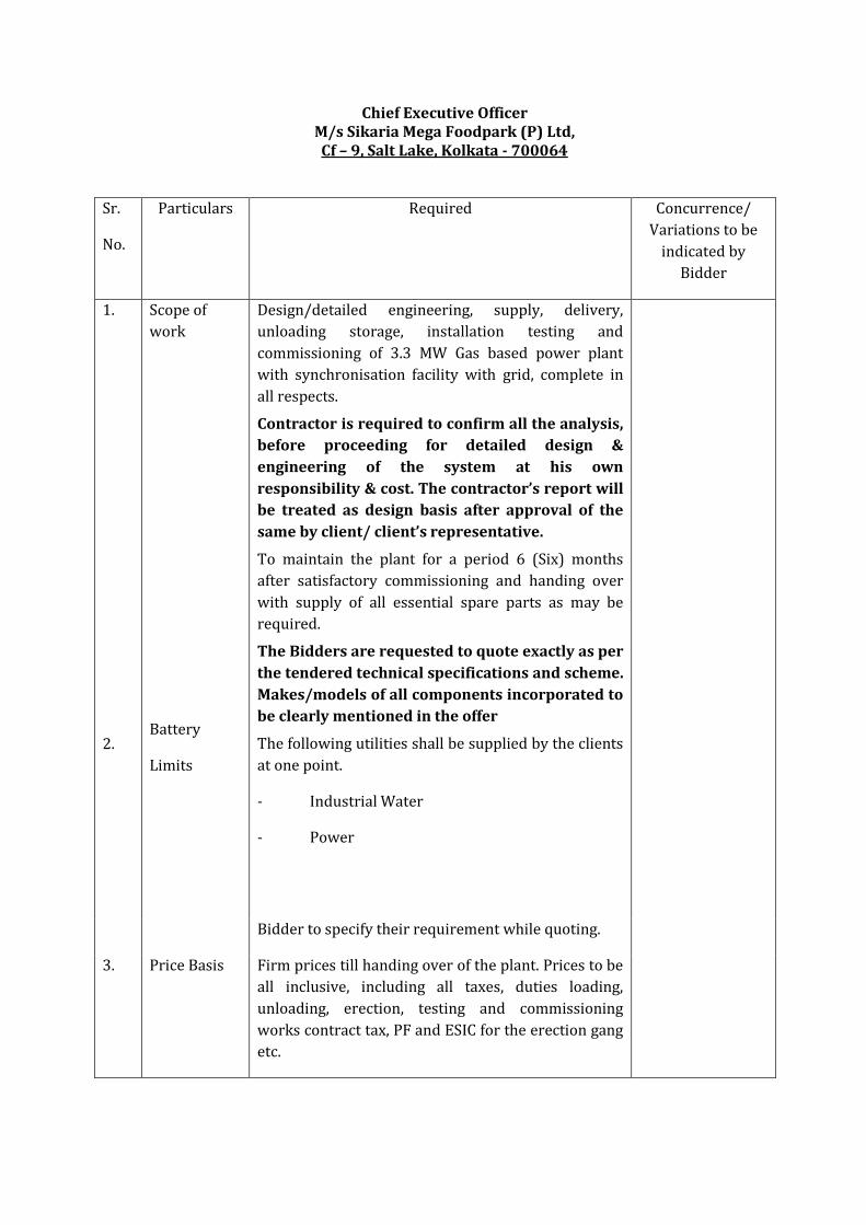
Chief Executive Officer M/s Sikaria Mega Foodpark (P) Ltd, Cf – 9, Salt Lake, Kolkata - 700064
Sr.
No.
Particulars Required Concurrence/
Variations to be
indicated by
Bidder
1.
2.
Scope of
work
Battery
Limits
Design/detailed engineering, supply, delivery,
unloading storage, installation testing and
commissioning of 3.3 MW Gas based power plant
with synchronisation facility with grid, complete in
all respects.
Contractor is required to confirm all the analysis,
before proceeding for detailed design &
engineering of the system at his own
responsibility & cost. The contractor’s report will
be treated as design basis after approval of the
same by client/ client’s representative.
To maintain the plant for a period 6 (Six) months
after satisfactory commissioning and handing over
with supply of all essential spare parts as may be
required.
The Bidders are requested to quote exactly as per
the tendered technical specifications and scheme.
Makes/models of all components incorporated to
be clearly mentioned in the offer
The following utilities shall be supplied by the clients
at one point.
- Industrial Water
- Power
Bidder to specify their requirement while quoting.
3. Price Basis Firm prices till handing over of the plant. Prices to be
all inclusive, including all taxes, duties loading,
unloading, erection, testing and commissioning
works contract tax, PF and ESIC for the erection gang
etc.

4. Terms of
Payment
10% Advance against submission of an on Demand Bank Guarantee/ Indemnity Bond valid up to planned &/or extended date of completion, as per format supplied by Client / Consultant
70% on pro rata erection. 15% on successful testing & commissioning 5% retention after handing over along with
various statutory permissions but can be
released against Approved Bank Guarantee
valid for 12 months from date of successful
commissioning & handing over.
5. Painting &
Protection
Painting with anticorrosive paint wherever
required and final painting of the plant of the
shade desired by client / consultant. A suitable
weatherproof covering for all pumps, motor
drives etc. shall be provided.
6. Commencem
ent of work
Date of issue of Letter of Intent/ Work Order /
Written acceptance by Client whichever is
earlier.
7. Completion
Period
6 months from date of LOI. A detailed time
schedule shall be prepared by the bidder and
submitted with his offer.
8. Defects
Liability
Period
12 months from the date of successful commissioning
& handing over.
9. Insurance The contractor shall take out following policies :
- Transit insurance for material under Transportation.
- Contractors all risk policy (CAR). - Third party insurance. - Workmen, compensation at 1 lakh per incident,
no. of incidents min. 3 Nos.
10. Validity of
Offer
90 days from the date of submission.
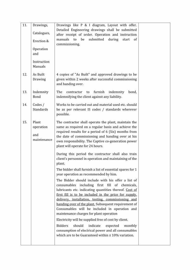
11. Drawings,
Catalogues,
Erection &
Operation
and
Instruction
Manuals
Drawings like P & I diagram, Layout with offer.
Detailed Engineering drawings shall be submitted
after receipt of order. Operation and instruction
manuals to be submitted during start of
commissioning.
12. As Built
Drawing
4 copies of "As Built" and approved drawings to be
given within 2 weeks after successful commissioning
and handing over.
13. Indemnity
Bond
The contractor to furnish indemnity bond,
indemnifying the client against any liability.
14. Codes /
Standards
Works to be carried out and material used etc. should
be as per relevant IS codes / standards wherever
possible.
15. Plant
operation
and
maintenance
The contractor shall operate the plant, maintain the
same as required on a regular basis and achieve the
required results for a period of 6 (Six) months from
the date of commissioning and handing over at his
own responsibility. The Captive co-generation power
plant will operate for 24 hours.
During this period the contractor shall also train
client’s personnel in operation and maintaining of the
plant.
The bidder shall furnish a list of essential spares for 1
year operation as recommended by him.
The Bidder should include with his offer a list of
consumables including first fill of chemicals,
lubricants etc. indicating quantities thereof. Cost of
first fill is to be included in the price for supply,
delivery, installation, testing, commissioning and
handing over of the plant. Subsequent requirement of
Consumables will be included in operation and
maintenance charges for plant operation
Electricity will be supplied free of cost by client.
Bidders should indicate expected monthly
consumption of electrical power and all consumables
which are to be Guaranteed within ± 10% variation.
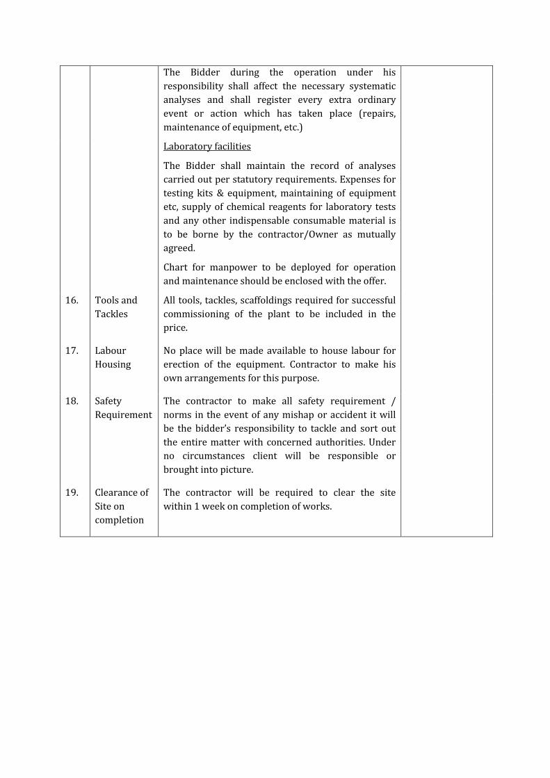
The Bidder during the operation under his
responsibility shall affect the necessary systematic
analyses and shall register every extra ordinary
event or action which has taken place (repairs,
maintenance of equipment, etc.)
Laboratory facilities
The Bidder shall maintain the record of analyses
carried out per statutory requirements. Expenses for
testing kits & equipment, maintaining of equipment
etc, supply of chemical reagents for laboratory tests
and any other indispensable consumable material is
to be borne by the contractor/Owner as mutually
agreed.
Chart for manpower to be deployed for operation
and maintenance should be enclosed with the offer.
16. Tools and
Tackles
All tools, tackles, scaffoldings required for successful
commissioning of the plant to be included in the
price.
17. Labour
Housing
No place will be made available to house labour for
erection of the equipment. Contractor to make his
own arrangements for this purpose.
18. Safety
Requirement
The contractor to make all safety requirement /
norms in the event of any mishap or accident it will
be the bidder’s responsibility to tackle and sort out
the entire matter with concerned authorities. Under
no circumstances client will be responsible or
brought into picture.
19. Clearance of
Site on
completion
The contractor will be required to clear the site
within 1 week on completion of works.

Specification for 3.3 MW Power plant
Content Specification for 3.3 MW Power plant 1.1 Introduction
An Energy Centre has been designed to provide year round Power for the Sikaria Mega
Food Park premises at Tulakona and Champamura Mouza, Agartala at Tripura.
Requirement of the power for the park will be gradually increased as the Load increases.
Energy conservation oriented combined heat and power generation plant has also been
thought & will be designed to achieve energy conservation.
Maximum Electrical Demand Load at present = 3.3 MWe, 11 kV, unity PF, 50 Hz ( Nett
Exportable)
Maximum HVAC Load = Not required at this Stage, however provisions need to be provided
with help of the Diverter system
To start with Energy Centre, we require 3.3 MWe which is expected to run on full Load so
as to feed the Power to the Food Park, in case the Power consumption is less in the Food
Park, we intend to export balance Power to the Grid which is a 33 kV.
In-case there is a Schedule Maintenance / Failure of the Gas Genset an Grid power will be
used to support Food Park.
The concept of Captive Power Plant is simple. i.e Generate power at the location by use of clean fuel Natural Gas as a fuel. Generate electricity by use of Gas engine and generate Chilled water use of Jacket Water and or Exhaust Gas, generate Steam by use of Exhaust Gases or generate power by use of ORC. Plant machinery in the plant room shall be placed on PCC/RCC foundation and provided with anti-vibratory supports. All foundations should be protected from mechanical damage by providing epoxy coated angle nosing. Seismic restraints requirement shall also be considered. Gas Gensets shall be housed in plant room area located on the Ground Level, Energy Centre Automation system shall be provided for maintaining necessary control of indoor temperature and humidity conditions and monitoring of plant functioning.

Magus Consulting Pvt Ltd has been appointed as PMC to provide engineering consultancy services for the project. In order to provide required utilities such as Electric power, Steam (Optional) and Chilled water (Optional) for the food Park and the auxiliaries, it has planned to set up power plant consisting of one (1) No High Efficient Natural Gas-fired Engine and Alternator, together with 11 KV, 3 phase, 50 Hz, Generator Control Panel, LT panel for Auxiliaries, connecting HT cables, Earthing, instrumentation and Piping, Step Up Transformer from 11 kV to 33 kV & Paralleling to the Grid. The power plant is to be set up on lump-sum turn-key contract. It is not the intent of this specification to completely specify all details of design and manufacture for the power plant. Nevertheless, the equipment / plant shall conform to high standards of design, engineering and workmanship in all respects and shall meet all the requirements of relevant codes and standards. Compliance to this specification shall not relieve the equipment/ plant manufacturer/vendor of the responsibility of supplying the equipment/ plant and auxiliaries of appropriate design, material and workmanship to meet the operating, safety, functional and maintenance requirements. In case of requirements of additional items, instruments, controls, safety devices and any other auxiliaries for safe, smooth and trouble free operation of the equipment, it shall be the responsibility of the equipment manufacturer / vendor to provide the same. Note: Vendor to submit the detailed scheme for generating the power at 11 KV and its synchronization with the grid in an approved manner.
1.2 Scope of work
Design, manufacture, inspection and testing, packing and forwarding, supply at site, unloading, storage at site, erection / installation, testing, 48 hours field / site trial run tests, site acceptance test, commissioning, handing over, training of owner’s personnel (at site), guarantee/ warrantee and operations during the defect liability period of 12 months including provision of spares, oil and consumables etc for power plant.
The scope of work also includes comprehensive Operations & Maintenance (O & M) for 24 months from the date of Starting of defect liability period. The work shall be handled through a separate O & M Contract. Although, initially the O&M contract shall be for 2 years, it may thereafter be extended up to 10 years plus. Vendors shall furnish the rate separately for each year of O&M upto 10 Years. Major Overhaul Chagres should be separately indicated.
1. The complete work is to be carried out on lump-sum ‘Turnkey’ basis and total contract value shall be inclusive of all applicable charges for insurances, taxes, duties, levies etc., However the Tax rates of all the above need to be mentioned separately which will be paid prevailing at the time billing.
2. Various parts of this specification shall be read in conjunction with each other and in case of differences, the more stringent requirement shall govern.
3. Any additional work/equipment or technical requirement, not mentioned in the specification but required to make the offered system complete in accordance with the specification or required for safe operation, shall be deemed to be included in the offer and provided by the vendor, with mutual agreement between Supplier, Buyer & Consultant. Any add on item supplied to make the system functional with our prior approval, Buyer will have full rights to reject those Bill & will be treated as Part of the Scope of the Agreement.
1. Scope of work and basis 1.2.1 The Power Plant Summary
Power plant shall be complete with, but not be limited to following. It is not the intent to completely specify all the details, equipment, item, accessories etc. of the package. Any additional work/equipment or technical requirement not mentioned hereunder but required to make the offered system complete in accordance with the specification or required for safe operation, shall be deemed to be included in the offer and provided by the Vendor, without any additional payment.
1. Appropriate size of Gas Mass flow meter along with local display, hooked up to power plant PLC via modbus and with isolated valves to measure the Natural Gas consumption at the package inlet point. All the mass flow meters shall be provided with one line test measurement. The Non Return Valve shall be installed to protect the flow meter against the back pressure.
2. Natural Gas pre-treatment system that may consist of gas filter suitable for pressure specified in the range of pressure with oil drain, temporary suction inline strainer and differential pressure gauge/ transmitter on strainer at the plant inlet before PRV. There shall be provision of temporary start up conical strainer fitted with adequate size mesh at the gas inlet before the filter.
3. Gas Inlet Pressure Regulator with SSV with an outlet discharge range to suit the gas engine inlet pressure, as applicable.
4. Gas engine
Four-stroke, air/gas mixture Turbocharged, After cooled, with High performance
ignition system and Electronically controlled air/gas mixture system. The engine
has to be equipped with the most advanced LEAN-BURN COMBUSTION SYSTEM.
Gas Train should be Pre-assembled, delivered loose, for installation into gas
pipework to the module. It should consist of :
• Main gas train: • Shut off valve • Gas filter, filter fineness <3 μm • Adapter with dismount to the pre-chamber gas train • Gas admission pressure regulator
• Pressure gauge with push button valve, 0-6 bar (0-87 psi) • High pressure regulator with safety-cut-off-valve (SAV) • Calming distance with reducer • Safety-blow-off-valve (SBV) • Pressure gauge with push button valve, 0-100 mbar (0-1,45 psi) • Solenoid valves • Leakage detector • Gas pressure regulator • Gas pressure switches (min., max.) • TEC JET (has to be implemented horizontal) The gas train complies with DIN - DVGW regulations. Maximum distance from TEC JET outlet to gas entry on engine, including flexible connections, is 1 m (39,37 in).
• Pre-chamber gas train: • Ball valve • Gas filter, filter fineness <3 μm • Solenoid valves • Pressure regulator • Calming distance with reducer • Pressure gauge with push button valve, 1-5 bar (0-72,5 psi)
Pre chamber gas pressure regulator (incl. stabilization section) assembled at the flexible connection pre chamber gas.
5. Engine Lube Oil System.
Should comprise of Gear-type lube oil pump to supply all moving parts with filtered
lube oil, pressure control valve, pressure relief valve and full-flow filter cartridges.
Cooling of the lube oil is arranged by a heat exchanger.
Automatic lube oil replenishing system should includes float valve in lube oil feed
line, including inspection glass. Electric monitoring system will be provided for
engine shut-down at lube oil levels "MINIMUM" and "MAXIMUM". Solenoid valve in
oil feed line is only activated during engine operation. Manual override of the
solenoid valve, for filling procedure during oil changes is included. Oil drain has to
be by set mounted cock.
Pre-lubrication- and aftercooling oil pump should be mounted on the module base
frame for pre-lubrication and aftercooling of the turbochargers.
Period of operation: Pre-lubrication: 1 minute both pumps
Aftercooling: 15 minutes from engine stop only the 415 V
pump
Pre-Lubrication system should be consisting of:
• 415V, 1 piece oil pump

• All necessary vents
• Necessary pipework
Any deviation to the Lubrication system mentioned above should be clearly
highlighted.
6. Exhaust gas system should be with minimum 30 mtr chimney height and ducting-separate as required for each Engine and shall be on basis of Natural Gas firing as per CPCB guide lines for power plant. Proper Connection of exhaust gas turbocharger; including flexible connection to compensate for expansions and vibrations has to be provided.
Exhaust gas scavenging blower has to be provided, The exhaust gas scavenging blower has to be used to scavenge the remaining exhaust gas out of the exhaust gas pipe work, to prevent the appearance of deflagrations. Its mandatory to provide because Before each start scavenging by blower has to done for app. 1 minute (except at black out – start). Safeties to this system should include like Scavenging air fan failure & Scavenging air flap failure. Any deviation to the Exhaust System mentioned above should be clearly highlighted.
7. System to be offered is with Electric Start only. It should comprise of 2 x 2 piece Pb battery with 12 cells, 2 x 12 V, 400 Ah (according to DIN 72311), complete with cover plate, terminals and acid tester. Battery voltage monitoring system has to be offered with Monitoring by an under voltage relay. Battery charging equipment offered should be Capable for charging the starter battery with I/U characteristic and for the supply of all connected D.C. consumers. Charging device should be mounted inside of the interface panel or control panel.
Battery Charging Panel should have latest design but limited to : • Power supply 3 Phase, 415 V, 50 Hz • Power consumption should be max to 2120 W • Nominal D.C. voltage 24 V(+/-1%) • Voltage setting range 24V to 28,8V ( adjustable) • Nominal current (max.) 2 x 2 x 40 A • Dimensions – Should be compact in design • Degree of protection IP20 to IEC 529 • Operating temperature 0 °C - 60 °C • Protection class 1 • Humidity class 3K3, no condensation. • Natural air convection • Standards EN60950,EN50178 UL/cUL (UL508/CSA 22.2) Should have the Signalling as under:
a. Green Led: Output voltage > 20,5V b. Yellow Led: Overload, Output Voltage < 20,5V c. Red Led: shutdown
8. Generator (alternator) The generator should consists of the main generator (built as rotating field machine), the exciter machine (built as rotating armature machine) and the voltage regulator with cos. phi-regulator. The regulator is powered by an auxiliary winding at the main stator.
Main components should not be limited to i. Main stator with frame
ii. Winding at two layers iii. Terminal box includes main terminals plus auxiliary terminals for
thermistor connection and control for regulator iv. Main rotor with sufficiently sized shaft dynamically balanced as per
VDI 2060, Grade Q1 v. Drive end bracket with bearing
vi. Non-drive end bracket with bearing vii. Exciter unit
viii. Power factor controller ix. Voltage regulator x. Anti-condensation heater
Electrical data and features
i. Voltage adjustment: +/- 10% rated voltage ii. Static voltage accuracy: +/- 1% at no load to full load and power
factor 0.8-1 iii. Speed variation +/- 3%, cold and hot machine iv. Maximum deviation of wave form according to VDE is 5% phase to
phase at open circuit v. Generator suitable for parallel operating with mains and other
generators vi. Sustained short circuit current at 3-pole terminal short circuit: minimum 3 times rated current for 5 seconds. vi. Overload capacity according. to IEC 32 - I/VDE 0530 vii. According to VDE 0530 the overspeed test ensues with 1.2 times of rated speed for 2 minutes.
9. Generator control panel should consist of 1 nos. incomer breakers receiving power from the generator.
This panel shall be provided with adequate metering and protections, as specified in the detailed specifications.
Power, control and signal cables and its auxiliaries Low voltage switchgear panels for auxiliaries load
Engine generator control panel Dimensions but not limited to • Height: 2200 mm (87 in) • Width: 1000 mm (40 in) • Depth: 600 mm (24 in) Control supply voltage from starter and control panel batteries: 24V DC
Supply of power for auxiliaries from auxiliary power panel: 3 x 415/240 V, 50 Hz, 35 A Panel should consist of: (Dialog Network new generation) motor management
system

System elements visualisation with central engine and module control 1) Visualisation: Industrial control with 10,4“ QVGA TFT colour graphics display and 8 function keys. 10-key numeric keyboard for parameter input. Keys for START, STOP, Generator circuit breaker OPEN, Generator circuit breaker CLOSED/SELECTED, display selection keys and special functions. Interfaces:
• Ethernet (twisted pair) for connection to DIA.NE WIN server • CAN-Bus: bus connection to the intelligent sensors and actuators • Data bus connection to the control in- and outputs
Protection class: IP 65 (front) A clear and functional graphic compilation of measured values has to be displayed on the screen. User prompts are to be meant of direct-acting display selection keys and function keys. Main displays: • Electrical schematic • Oil and hydraulic schematic • Gas data • Engine controllers • Cylinder data • Exhaust gas data • Auxilliaries controllers • Spare screen for customer specific purposes • System display screens • Parameter manager • User setting • Alarm management
Recipe handling: Setting, display and storage of all module parameters Alarm management: Efficient diagnostic instrumentation listing all active fault messages both tabular and chronologically, with the recorded time. Central engine and module control should have A real-time, modular industrial control system which handles all jobs for module and engine-side sequencing control (start preparation, start, stop, synchronizing, after-cooling, control of auxiliaries), as well as all control functions. Control functions: • Speed control in no-load and isolated operation • Power output control in parallel operation system; job-specific with respect to internal and external set point values.
• Control system should control boost pressure; dependent upon the generator terminal power and the mixture temperature via the engine-driven air-gas mixer • Knocking control: adjustment of the ignition point, power output and (insofar as is locally possible) the mixture temperature in the event of detection of knocking. • Load sharing between several modules in isolated operation • Linear reduction of power output in the event of excessive mixture temperature
and ignition failures • Interface relays as per the interface list • Multi-transducer, to record the following electrically measured variables of the
generator: • Phase current (with slave pointer) • Neutral conductor current • Voltages Ph/Ph and Ph/N • Active power (with slave pointer) • Reactive power • Apparent power • Power factor • Frequency
The following alternator supervisions has to be integrated with the multi-transducer (max. 8 functions simultaneous): • Overload/short-circuit [51], [50] • Over voltage [59] • Undervoltage [27] • Asymmetric voltage [64], [59N] • Unbalance current [46] • Failure Exitation [40] • Overfrequency [81>] • Underfrequency [81<] • Lockable operation mode selector switch positions: Any other parameter which is not mentioned but required shall be considered No operation should be possible, running set will shut down;

• "MANUAL" Manual operation using (start, stop) is possible, unit is not available for fully automatic operation. • "AUTOMATIC" Fully automatic operation, according to remote demand signal: • Automatic start
Fully automatic operation at full load • Stop with cooling down run for 1 minute
Continuous operation of auxiliaries for 5 minutes after engine shutdown • Demand switch with the positions: • Demand OFF • Demand ON • Remote demand • Supply disconnecting device for auxiliaries with lockable circuit breaker
Shut-down functions has to be with display: • Low lube oil pressure • Low lube oil level • High lube oil level • High lube oil temperature • Low jacket water pressure • High jacket water pressure • High jacket water temperature • Overspeed • Emergency stop/safety loop • Gas train failure • Start failure • Stop failure • Engine start blocked • Engine operation blocked • Misfiring • High mixture temperature • Measuring signal failure • Overload/output signal failure • Generator overload/short circuit • Generator over/undervoltage • Generator over/underfrequency • Generator asymmetric voltage • Generator unbalanced load • Generator reverse power • High generator winding temperature • Synchronising failure • Knocking failure Warning functions with display: • Low jacket water temperature • CPU battery failure Operational functions with display: 27.09.2011/1 Technical Specification J620 JMS.doc Copyright ©(rg) 22/31 • Ready to start • Operation (engine running) • Generator circuit breaker "CLOSED"
10. Complete earthing & lightning protection required including civil construction of earthing pit chamber/surround the Power Plants.
11. All interconnecting piping/ ducting for natural gas, flue gas, exhaust gas, air, water, blow-down, drain, etc. as applicable.
12. Strainers/ filter, valves, sight flow indicators, check valves, auto and manual drain traps etc. as required for various auxiliary systems i.e. frame lube oil, cylinder lubrication system, cooling water systems, if applicable, etc.
13. Coupling/V-belts/pulleys.

14. All electrical power and control cables with glands etc.
15. All instrument power and control cables with glands etc.
16. Instrumentation and control system as specified including Local panel, Console/Local gauge boards, PLC etc. The PLC shall have provision of 100% redundancy to avoid downtime and loss of data in case of any problem. The PLC shall have necessary provision for communications with centralised DCS.
17. Common structural steel skid for the complete plant including all auxiliary equipment/ systems/ items etc. including control panel.
18. All necessary structural steel for support, railing, ladders, platforms, cable tray, etc.
19. Separate junction boxes for different type of signals such as intrinsically safe signals, alarm, shutdowns, thermocouples, RTDs etc. for interfacing to local panel.
20. Structural supports within the plant package for all tubing, piping, instruments etc. and all tube welds.
21. Inlet and outlet manual and automatic isolating valves for maintenance and emergency.
22. Minimum two numbers of emergency stop switch shall be provided outside the plant area for easy access in case of emergency. All the systems shall cease the operations including gas supply and electricity generation shall be stopped immediately upon energising the emergency switch in case of emergency. Vendor shall consider 50m cable length for the same.
23. Plant unloading arrangement
24. Lifting lug Arrangement for installation and maintenance
25. Mandatory spares as required for erection, maintenance and commissioning.
26. Signage for Warning and Operating instructions to be displayed at equipment as per the statutory/safety regulations
27. Provision and fixing of foundation bolts and grouting of all equipment, frames, supports etc., if any
28. Provision of all tools, tackles, consumables, first charge, spares, equipment and instruments required for erection, commissioning and carrying out Site Acceptance Test (SAT)
29. General arrangement and detailed layout drawings with static and dynamic load and fixing details to enable the Owner to design and provide the necessary civil/ RCC work.
30. Documents as specified under Non Material Requirements
31. Provision of temporary electric power for construction/ erection/ installation will be provided by Buyer.
32. DCS and SCADA system optional to be quoted.
1.3 Battery limits
a. Natural gas: Available from the grid supply at 3- 5 kg/cm2 (g) pressure. The properties of gas shall be as per Appendix-A. The gas connection details at the battery limit is not known yet and it shall be vendor’s responsibility to provide necessary flanged connection at the battery limits.
b. Flue gas: At the exhaust of chimney.
c. HT Electric power (11 KV) as produced from the generator: At the outgoing
terminals of generator control panel. LT electric power (415 V AC): shall be made available by the owner at one point only at the incoming terminals of incoming MCCB or ACB at MCC for auxiliary load. The MCC shall be supplied by the vendor. It shall be vendor’s responsibility to make necessary provisions for 230 V AC,110 V DC and 24 V DC and their further distribution. However the necessary DG set for the auxiliary power to be quoted by the Vendor separately.
d. The cooling tower and necessary transfer system are in scope of vendor. e. Step up Transformer from 11 kV to 33 kV of the required capacity shall be in the
scope of vendors only. f. Grid Paralleling System shall be supplied by the vendor
1.4 Exclusion
All civil / RCC work. However, minor work related to chipping, supporting, grouting etc. shall be
included in the scope of vendor. However it is to be noted that all the details required for the designing of the building shall be provided by the suppliers like Load data, necessary GA drawing
Fencing for complete power plant as per the local PCC and CCOE norms Fire protection system Statutory approvals legal charges only. (All the statutory approval to be taken care
by the vendors.) 1.5 Site particulars
Project Site address : Tulakona Mouza and Champamura Mouza
Agartala, Tripura
Height above Mean Sea Level >>>>>>>>>>>>> Average Max. Temperature >>>>>>>>>>>> Average Min. Temperature >>>>>>>>> Design Max. Temperature >>>>>>>>>> Project
Design Min. Temperature >>>>>>>>>>>>>> Humidity, Maximum >>>>>>>>>>>>>> Humidity, Minimum >>>>>>>>>>>>>>> Average Annual Rainfall>>>>>>>>>>>>>>>>>>>>>>> Prevailing Wind Direction>>>>>>>>>>>>>> Designed Wind Velocity >>>>>>>>>>>>>>>>> Seismic Zone >>>>>>>>>>>>>>>>> Nature of Soil >>>>>>>>>>>>>>>
Environment Normal industrial 1.6 General purchase conditions
1.6.1 Qualification Criteria ( apart from the one mentioned in NIT) 1. The Vendor shall have the single point responsibility for the complete work. 2. The Vendor shall be a regular manufacturer and supplier of the specified equipment / package. 3. The vendor shall have full-fledged service support set-up in India or have appropriate arrangements for the same with the established local reputed company. 4. The offered packages shall be of proven make from the existing production range of the
manufacturer of major equipment such as engine, generator, air compressor, motor etc. and must meet performance requirement as stated in the specifications.
5. Turnover of the Supplier shall not be less than 50 Cr in last three financial years. 1.6.2 Bid submission 1. Two separate copies of bid as mentioned in the NIT to be submitted in a separate sealed envelopes, super scribed with the item and due date. 2. The equipment / package are to be offered on lump sum price basis.

3. The rates for erection and commissioning shall be furnished separately. 4. The rates for mandatory spares for 2 years shall be furnished separately. 5. Vendor shall clearly mention whether equipment shall be transported in fully assembled condition or in a knocked down condition and to be assembled at site. Vendor shall punch match marks to avoid confusion at site. 6. Vendors are advised to quote strictly as per terms and conditions of the tender documents and clearly stipulate any deviations / exceptions or alternate design. The deviations / exceptions shall be listed separately for each specification / document with cross-references and proper reasons for the deviations / exceptions. In case of any deviation not listed under the ‘List of deviations / exceptions to the specifications’ but appear in other part of the bid, the same shall not be considered/ applicable. 7. The price quoted by the vendor shall also include Cost of all services required as per scope of work and all taxes & duties including WCT/VAT/Service tax. 8. All taxes, duties, other statutory levies and rate thereof as applicable to due date of submission of Bid shall be included in the quoted prices. 9. Prices quoted by the Vendor, shall remain firm and fixed and valid until completion of the Contract performance and will not be subject to variation on any account except for statutory variation in taxes and duties on finished products in Owner’s country against documentary evidence. 10. Rates quoted by the Vendors shall be firm and valid even if the contract is split.
11. The Vendors shall be deemed to have been allowed in his rates and prices for the provision, maintenance and final removal of all temporary works of whatsoever nature. No specific item of any or particular temporary shed/work will be measured and paid for separately. 12. Any of the item rates quoted shall be valid even if the related item of work is executed or deleted in full or part thereof. 13. Please note that the owner/ purchaser reserve the right to reject any or all the vendors and accept complete or partial bids without assigning any reasons thereof.
2.1 Codes and standards Codes Description ISO 15550 Engine SAEJ 1349 Engine Power Test Code ISO 8528 Part 9 Design EN 13480 and DIN 2413 Pipe design calculations EN 1011 Welding ISO Stair and platforms DIN, ISO, SFS and EN Dimensional standards for installation materials (pipes, beams, etc.) API 650 Tanks

DIN, SFS and EN Typical material standards IEC 60034 Generator IEC 60076 Transformer, Oil type IEC 60726 Transformer, Dry type IEC 60298, IEC 62271 Medium Voltage Switchgear IEC 60439-1 Low Voltage Switchgear IEC 60529 Enclosure protection IEC 60950 WOIS workstation hardware Applicable parts of VDE 3699 WOIS workstation software IEEE 80 Earthing network IEC 60439-1 Control panels IEC 61131-3 PLC software EN 34 Fire detection IEC 1024 Protection of structures against lightning Codes Description IEC 34-3 Specifications for rotating electrical machines IS 7132 Guide for testing synchronous machines IEC 34-2 Method for determining losses and efficiency of rotating electrical machinery from test IEC 34-4 Methods of determining synchronous machine quantities from test IEC 34-5 Classification of degree of protection provided by enclosures for rotating machines IEC 34-6 Methods of cooling rotating machinery IEC 34-8 Terminal marking and direction of rotation for rotating machines IS 3003 Specification for carbon brushes of electrical machine
2.2 General requirements 1. The equipment covered by this Specification shall be suitable for the specified operating conditions and shall be designed and constructed for a minimum service life of 20 years, and at least 2 years of uninterrupted continuous service, where operation exceeds 8100 hours per year with uninterrupted periods of 1000 hours minimum. Except for Scheduled Maintenance, Annual overhauls, shutdowns for maintenance shall not exceed 24 hours. It is recognized that this is a design criterion and that uninterrupted operation for this period of time involves factors beyond the Vendor's control. 2. The continuous rating at site conditions for all engines shall be equal to the maximum required power of the driven equipment, including the losses in any intermediate transmission. 3. The equipment shall be located as under and equipment layout shall be prepared accordingly.
_ Engine and generator – on ground floor _ Other equipment and accessories to suit the technical requirements
4. Noise levels for each new piece of equipment or integrated unit shall not exceed 85 dB (A) at a distance of one meter from the Power Plant Room
2.3 Gas engine The power plant shall be designed for base load operation requirement of 3.3 MWe. 1 No . Natural Gas fired power generating engine set shall be sized accordingly. 2.3.1 Design 1. Engine shall be capable of starting at 5°C on straight natural gas and shall be capable of running on natural gas. 2. Engine shall be capable to run without de-rating factor up to Methane No. 70, Anything deviation to it should be clearly highlighted. In case there is any benefit by deviating the requirement, same shall be considered. 3. For engine in continuous service, fuel filters shall be of the full flow, cartridge type having a filter mesh not exceeding 10 micrometers. 4. The engine shall be equipped with a safe barring device to facilitate easy inspection and maintenance of the engine. When dictated by torque requirements, the barring device shall be pneumatically or electrically powered. An interlock with indication shall be provided to prevent starting the engine when the barring device is engaged. 5. Air intake filters shall be provided and air intake filters shall be a combined inertial separator and dry filter arrangement with a differential pressure indicator. 6. All engines shall be equipped with inlet/exhaust valve seals. The seals shall be of the rubbing contact type, with an electrometric or Teflon insert. 7. Each engine shall be equipped with an exhaust silencer. 8. Governors for all mechanical drive applications shall be in accordance with the above Codes specified. An over-speed device shall be provided which overrides the governor action. An additional air choke closing on the over-speed signal shall be provided in the inlet
piping. The over-speed trip setting shall be 10% above the maximum continuous operating speed of the driver/driven equipment train. 9. The starting system shall be capable of handling a minimum of 3 consecutive starts, In case if it fails to Start it should give an alarm like overcrank. 10. Engine cooling systems, either water-cooled or air-cooled, shall have sufficient capacity to maintain stable operating temperatures at the maximum engine output and under the worst site conditions of temperature, altitude and humidity. 11. The main engine driven lube oil pump shall be easily accessible for maintenance. 12. An oil cooler shall be provided to limit the lube oil temperature in the oil pan at the oil pump inlet to a maximum of 120°C. 13. Lube oil filters shall be located downstream of the lube oil cooler. Filter cartridges shall have a mesh of 10 micrometers, maximum.
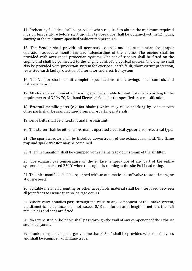
14. Preheating facilities shall be provided when required to obtain the minimum required lube oil temperature before start up. This temperature shall be obtained within 12 hours, starting at the minimum specified ambient temperature. 15. The Vendor shall provide all necessary controls and instrumentation for proper operation, adequate monitoring and safeguarding of the engine. The engine shall be provided with over-speed protection systems. One set of sensors shall be fitted on the engine and shall be connected to the engine control’s electrical system. The engine shall also be provided with protection system for overload, earth fault, short circuit protection, restricted earth fault protection of alternator and electrical system 16. The Vendor shall submit complete specifications and drawings of all controls and instrumentation. 17. All electrical equipment and wiring shall be suitable for and installed according to the requirements of NFPA 70, National Electrical Code for the specified area classification. 18. External metallic parts (e.g. fan blades) which may cause sparking by contact with other parts shall be manufactured from non-sparking materials. 19. Drive belts shall be anti-static and fire resistant. 20. The starter shall be either an AC mains operated electrical type or a non-electrical type. 21. The spark arrestor shall be installed downstream of the exhaust manifold. The flame trap and spark arrestor may be combined. 22. The inlet manifold shall be equipped with a flame trap downstream of the air filter. 23. The exhaust gas temperature or the surface temperature of any part of the entire system shall not exceed 250°C when the engine is running at the site Full Load rating. 24. The inlet manifold shall be equipped with an automatic shutoff valve to stop the engine at over-speed. 26. Suitable metal clad jointing or other acceptable material shall be interposed between all joint faces to ensure that no leakage occurs. 27. Where valve spindles pass through the walls of any component of the intake system, the diametrical clearance shall not exceed 0.13 mm for an axial length of not less than 25 mm, unless end caps are fitted. 28. No screw, stud or bolt hole shall pass through the wall of any component of the exhaust and inlet system. 29. Crank casings having a larger volume than 0.5 m³ shall be provided with relief devices and shall be equipped with flame traps.

30. The engine nameplate shall be marked to show the Class, Division and Group for which it is qualified. 31. Engine shall be designed to permit rapid and economical maintenance. 32. Major parts such as casing components, cylinder heads, etc., shall be designed (shouldered or doweled) and manufactured to ensure accurate alignment on reassembly. 33. Engines shall be arranged such that sufficient space is available to permit removal of the oil pan without the need to remove the engine from its base plate. 34. The package shall include any special tools required for disassembly and reassembly of the unit. These shall be packed separately and clearly labelled as special tools for the designated unit. 35. An operating and maintenance instruction manual shall be included as part of the package. This manual shall provide sufficient written instructions, including a cross referenced list of all drawings, to enable the Owner to correctly install, operate and maintain the unit. As a minimum, the manual shall contain the following information:
a. Instructions covering start up, normal shutdown, emergency shutdown, operating limits and routine operational procedures. b. A description of the constructional features and the functioning of the component parts and systems (such as controls, the lube oil, turbocharger, fuel injection, cooling systems, etc.). c. Outline and sectional arrangement drawings, schematics and illustrative sketches to identify all parts and clearly show the operation of all equipment and components and the methods of inspection and repair. d. Standardized sectional arrangement drawings are acceptable only if they represent the actual construction of the engine being supplied. e. As built data sheets containing all required information. f. The following maintenance data:
− Maximum and minimum bearing and seal clearances. − Instructions for measuring and adjusting cold clearances. − Crankshaft floats allowance. − Crankshaft dimensions and regrinds allowance, if applicable. − Interference fits on parts required to be removed or replaced. − Run out and concentricity tolerances. − Cylinder bore dimensions. − Piston ring clearance and wear data.
g. The following re-assembly data:
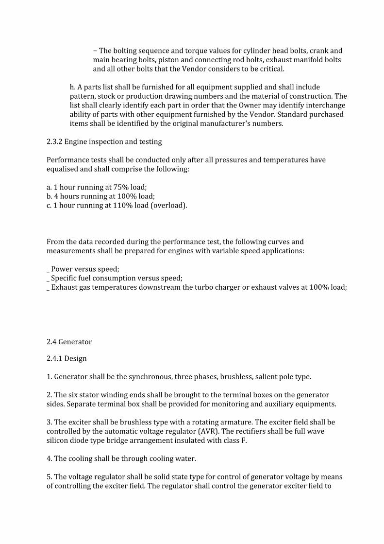
− The bolting sequence and torque values for cylinder head bolts, crank and main bearing bolts, piston and connecting rod bolts, exhaust manifold bolts and all other bolts that the Vendor considers to be critical.
h. A parts list shall be furnished for all equipment supplied and shall include pattern, stock or production drawing numbers and the material of construction. The list shall clearly identify each part in order that the Owner may identify interchange ability of parts with other equipment furnished by the Vendor. Standard purchased items shall be identified by the original manufacturer's numbers.
2.3.2 Engine inspection and testing Performance tests shall be conducted only after all pressures and temperatures have equalised and shall comprise the following: a. 1 hour running at 75% load; b. 4 hours running at 100% load; c. 1 hour running at 110% load (overload). From the data recorded during the performance test, the following curves and measurements shall be prepared for engines with variable speed applications: _ Power versus speed; _ Specific fuel consumption versus speed; _ Exhaust gas temperatures downstream the turbo charger or exhaust valves at 100% load; 2.4 Generator
2.4.1 Design 1. Generator shall be the synchronous, three phases, brushless, salient pole type. 2. The six stator winding ends shall be brought to the terminal boxes on the generator sides. Separate terminal box shall be provided for monitoring and auxiliary equipments. 3. The exciter shall be brushless type with a rotating armature. The exciter field shall be controlled by the automatic voltage regulator (AVR). The rectifiers shall be full wave silicon diode type bridge arrangement insulated with class F. 4. The cooling shall be through cooling water. 5. The voltage regulator shall be solid state type for control of generator voltage by means of controlling the exciter field. The regulator shall control the generator exciter field to
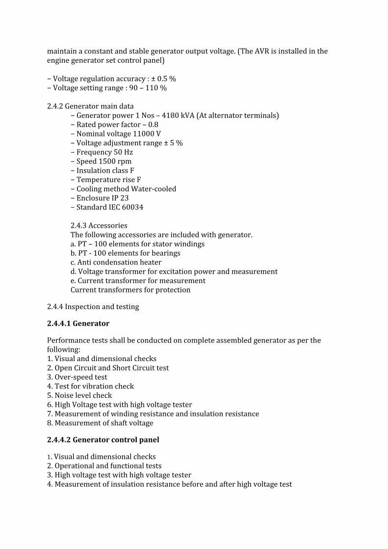
maintain a constant and stable generator output voltage. (The AVR is installed in the engine generator set control panel) − Voltage regulation accuracy : ± 0.5 % − Voltage setting range : 90 – 110 % 2.4.2 Generator main data
− Generator power 1 Nos – 4180 kVA (At alternator terminals) − Rated power factor – 0.8 − Nominal voltage 11000 V − Voltage adjustment range ± 5 % − Frequency 50 Hz − Speed 1500 rpm − Insulation class F − Temperature rise F − Cooling method Water-cooled − Enclosure IP 23 − Standard IEC 60034 2.4.3 Accessories The following accessories are included with generator. a. PT – 100 elements for stator windings b. PT - 100 elements for bearings c. Anti condensation heater d. Voltage transformer for excitation power and measurement e. Current transformer for measurement Current transformers for protection
2.4.4 Inspection and testing
2.4.4.1 Generator
Performance tests shall be conducted on complete assembled generator as per the following: 1. Visual and dimensional checks 2. Open Circuit and Short Circuit test 3. Over-speed test 4. Test for vibration check 5. Noise level check 6. High Voltage test with high voltage tester 7. Measurement of winding resistance and insulation resistance 8. Measurement of shaft voltage
2.4.4.2 Generator control panel
1. Visual and dimensional checks 2. Operational and functional tests 3. High voltage test with high voltage tester 4. Measurement of insulation resistance before and after high voltage test

2.5 Accessories between engine and generator 2.5.1 Common accessories _ The engine and generator shall be rigidly mounted on a common base frame, supply shall include bolts, nuts, washers and steel chocks etc. for testing the same _ Elastic mounting shall be used to reduce the dynamic forces to the concrete foundation block _ Sylomer Vibration pads shall be installed between the common base frame and the concrete foundation block. _ Flexible coupling shall be provided between the engine flywheel and the generator to transmit the torque from the engine to the generator. _ Flexible hoses and bellows shall be provided for installation between the generating set and external piping system. _ Following flexible connections shall be provided for auxiliary system Cooling water Lubricating oil Exhaust gas Fuel Crankcase ventilation _ Vendor shall provide prefabricated maintenance platforms with stair and rails for engine and between modules. 2.5.2 Mechanical auxiliary system The engine mechanical auxiliary system shall comprise of following, unless otherwise specified. _ Engine lube oil system − Plant lube oil system _ Cooling system − Engine cooling system by cooling tower water. Cooling tower & cooling tower pumps of suitable rating, piping and other accessories shall be provided by the vendor. _ Charge air system _ Exhaust gas system _ Turbocharger and Air to Fuel ratio control system _ Steel structures − Support for exhaust gas duct in side CPP House and outside up to stack etc with isolation and bypass dampers with expansion joint. − Piping and cable support inside and outside CPP house − Support structure for pipe / cable rack. 2.6 HT Switchboard (Generator Control Panel-Drg No._________________________)
1. Vendor to quote for 11 KV HT switchboard considering three (1) nos. Incomer VSB of 500 Amps for Gas Generator supply with bus-coupler & Grid supply breakers of 500 Amps and two (1) nos. outgoing feeders with VCBs to be provided. The panel shall be extensible on both sides for future Gas Generator set expansion.

2. 11 KV HT Switchboard shall be provided with air insulated, metal enclosed and withdraw able Circuit breakers rated for 11 KV. The switchboard shall have degree of protection IP-42. For detailed specifications refer “Specifications for High Tension Switchboard.”
3. The HT Switchboard circuit breakers shall be equipped with auxiliary contacts, spring charging motors, closing and shunt tripping coils, current and voltage transformers with accuracy class for protection transformers being 5P10 and for measuring transformers, being 0.5. The rated short circuit current shall be 31.5 KA (600 MVA).
4. Main switchgear consists of following feeders:-
5. Incoming Gas Generator & grid power supply cubicle consists of Vacuum circuit breaker, CT’s, PT’s, Core balance CT for earth fault, Breaker control switch, Earthing switch & a set of auxiliary relays, Wattmeter, kWh meter, Ammeters, voltmeter etc. with all respective protective relays (Differential protection, Power monitoring unit (PMU), O.C., S.C. & E/F relay, Over/Under voltage and frequency relays, Negative phase sequence relay, Loss of excitation) 6. Bus-coupler cubicle consists of Vacuum circuit breaker, CT’s, Core balance CT for earth fault, Breaker control switch, Earthing switch, Ammeters, etc. with necessary protective relays (O.C., S.C., E/F and auxiliary relay for these protections) 7. Outgoing cubicle(s), 02 Nos. consisting of Vacuum circuit breaker, CT’s, PT’s, Breaker control switch, Earthing switch & a set of auxiliary relays and 3 Phase over current, short circuit protection and earth fault Relay, REF and MFM, Ammeters, voltmeter etc.
8. 1 No: - Bus-bar cubicle consists of voltage Transformer, voltmeter & selector switch, MCBs. 9. 1 No: - Neutral grounding transformer consisting of neutral grounding resistor, off-load dis-connector or Vacuum contactor, current transformer etc. 2.6.1 Cable accessories for HT switchboard
H. T. cables shall be as per “Specifications for H. T. Cable. _ 1 Set(s) of XLPE insulated Al. Conductor, high voltage cables between generator and generator cubicle. _ 1 Set(s) of XLPE insulated Al. Conductor, 1 core / 3 core type, medium voltage cables between generator and generator neutral point cubicle. _ 1 Set of necessary cable joints and fittings for above mentioned cables. 2.7 Auxiliary equipments for main system
2.7.1 Low voltage switchgear (Motor control centre for auxiliary equipments) 1. Low voltage switchgear panels shall be sheet-steel enclosed 3 phase, 4 wire cubicle-type compartmentalised construction with degree of protection IP54. Aluminium bus bars shall be rated as applicable fault level. For detailed specifications refer “Specifications for Low Voltage Switchgear Panel.

2. The switchgear shall consist of the following equipment:
a. Main Incoming feeder shall be provided with draw out type MCCB or electrically (motor) operated draw out type ACB as per total load for auxiliary equipments. If MCCB is provided, the same shall be provided with thermal magnetic release for short circuit and over current protection and microprocessor based earth fault release for earth fault protection with digital type multi function metering. However, if ACB is provided, the same shall be provided with microprocessor based over load, short circuit and earth fault release with digital type multi function metering. Emergency incomer for emergency load shall be provided with adequately rated switch fuse unit.. Outgoing feeders shall be provided with various types of starters for control of auxiliaries required by the Vendor for the system. The details of auxiliaries with their load shall be furnished by Vendors along with their offers. 2.7.2 LV power and control cables / accessories LV power and control cables shall be as per “Specifications for L. V. Cable. 1 Set of Al conductor low voltage cables inside the power house for vendor’s equipment 1 Set of low voltage PVC insulated Cu conductor control cables of 1.5 sq. mm. conductor size. 1 Set of necessary joints and fittings for above mentioned cables.
2.8 DC system (common) The power plant shall be equipped with DC system which feeds the DC power to the control, automation, protection and alarm systems to ensure safe operation and shutdown of the plant in case of a failure in the AC based station service system. The Battery / Battery Charger capacity and DC distribution board shall be supplied by the Vendor as per the system requirement. Battery shall be Lead acid Sealed Maintenance Free (SMF) type. Battery backup shall be suitable for 10 hours duration. No. of outgoing feeder from DCDB shall be as per requirement and shall consist of MCBs of required rating. For detailed specifications refer “Specifications for Battery and Battery Charger.
2.9 Flue gas bypass (diverter) valve Normally the flue gas will pass through Waste heat recovery boiler (WHRB). During starting and otherwise due to any emergency it may be required to by pass the WHRB and the flue gas may be diverted to chimney and for which a flue gas diverter / bypass valve / damper shall be provided.
2.10 Waste heat recovery boiler (Optional) The heat in the flue gas, generated from the combustion in the engine shall be utilised to produce steam through a waste heat recovery steam boiler (WHRB) having three compartmental coil arrangement. The inlet water to the coil shall be from the rear end (chimney side) of the WHRB coil set for the feed water pre heating purpose (for economiser effect) & then the preheated water shall pass through the front end (gas engine side) heat absorbing coil compartments.
2.11 Vapour Absorption Machine (Optional) 2.12.1 Design basis _ Energy Source : Hot water from natural gas fired engine (HT circuit)

_ Type : single stage or two stage absorption refrigeration cycle using water as the refrigerant and lithium bromide as the absorbent − Chilled water inlet temp : 12 OC − Chilled water outlet temp : 07 OC
2.12 Central monitoring system 2.13.1 General 1. The offered control system shall be stand-alone operator interface system (OIS) with SCADA to be provided at centralized control room. 2. The monitoring and supervision system shall be designed for safe, reliable, efficient and easy operation of the generating sets, their associated auxiliaries and electrical systems. 3. The power plant shall be monitor from the Operator’s Interface System (OIS workstations) from the control room and generating set sections. 4. The OIS workstation and generating set control panels shall be located in the control room where all the main supervision of the plant takes place. 5. The system shall have extensive set of self-diagnostic hardware and software for easy and fast maintenance of PLC. Routine checks should run automatically at frequent intervals for identifying any fault in software or hardware. Diagnostics shall be requested at local as well as OIS level. 6. The proposed system shall be located in non-hazardous and controlled environments. 7. The control room shall be Air conditioned and temperature may range from 20-25 deg. C with 30-65% RH.

2.13.2 Operator workstation
The power plant shall be supervised from the Operator Interface System (OIS workstation). All actions necessary for the normal operation, such as start and stop of the generating sets, load increase and load reduction shall be supervised via the OIS workstation, using a mouse, keyboard and display. The operator shall also be able to supervise various temperatures and pressures as well as measurement of generator power, voltage and frequency. The OIS workstation shall contain the following equipment: _ 1 Desktop PC computer sufficient memory. _ 1 Display, LCD screen 19” _ 1 Keyboard and optical mouse _ 1 Laser printer for hard copy and report printing _ 1 Operating system _ 1 Human-Machine-Interface (HMI) software _ Workstation complete with tables & chairs.
2.14 Piping _ Design, fabrication, erection and testing code : ASME B 31.3 _ All gas tubing shall be Stainless Steel series –316 conforming to ASTM-A269 with maximum hardness of Rb80. _ The instrument gas tubing material shall be Stainless Steel series –316 conforming to ASTM-A269. _ All lube oil piping down stream of filter shall be Stainless Steel 304. _ All carbon steel piping shall be seamless in accordance with ASTM A- 53 Gr. B or ASTM A – 106 Grade B and not less than 1" nominal size. _ All vent and drain line shall be provided double valve combination of gate & globe valve as per std. _ All the elements of tubing and/or piping shall be designed for the full range of pressures, temperatures and loading to which they may be subjected with a factor of safety of at least 4 (four) based on the minimum specified tensile strength at 20°C. _ All high pressure stainless tubing shall be installed with heavy duty clamp at an interval of distance not more than 1500 mm. and shall be clamped at all joints. _ Open ends on fittings and vents shall be provided with caps. _ Inspection and testing at site: All tubing work shall be hydro-tested at a pressure of 1.5 times the maximum working pressure. After completion of the hydro-test, all the lines shall be flushed and dried with air. The pneumatic test shall also be carried out at the maximum available pressure but not less than 100 kg/cm2 (g). .
3. Data required from the vendor
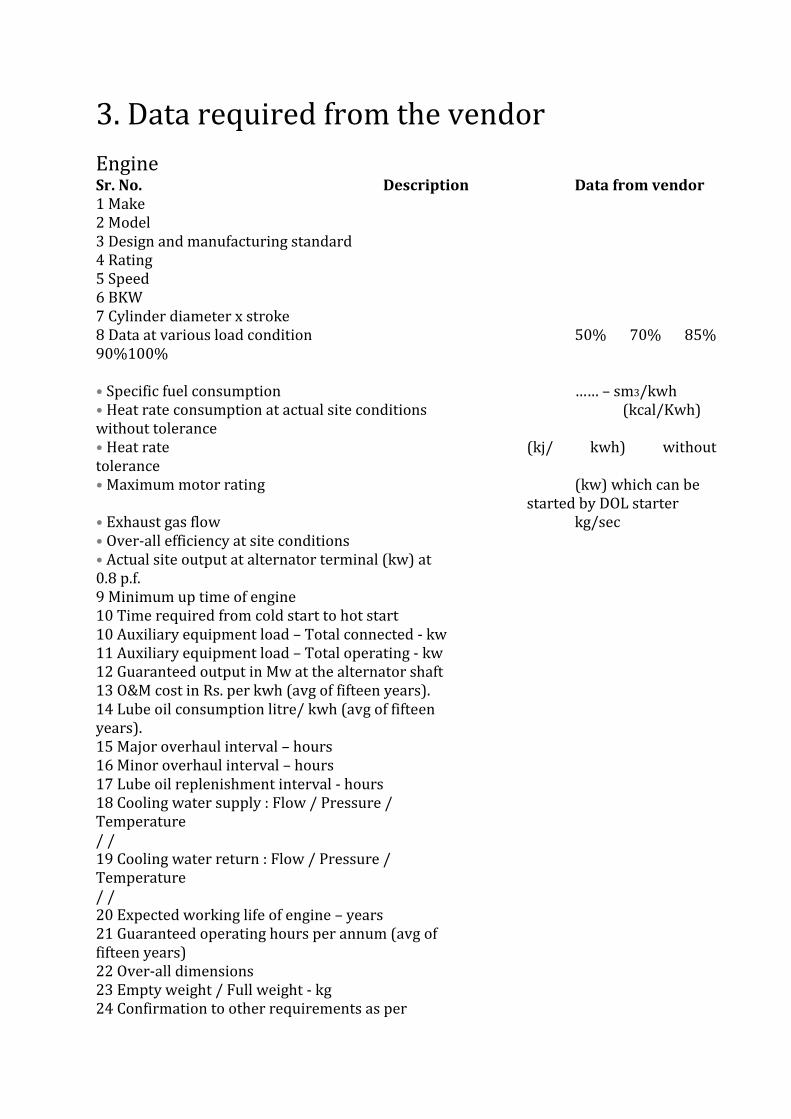
Engine Sr. No. Description Data from vendor 1 Make 2 Model 3 Design and manufacturing standard 4 Rating 5 Speed 6 BKW 7 Cylinder diameter x stroke 8 Data at various load condition 50% 70% 85% 90%100% • Specific fuel consumption …… – sm3/kwh • Heat rate consumption at actual site conditions (kcal/Kwh) without tolerance • Heat rate (kj/ kwh) without tolerance • Maximum motor rating (kw) which can be
started by DOL starter • Exhaust gas flow kg/sec • Over-all efficiency at site conditions • Actual site output at alternator terminal (kw) at 0.8 p.f. 9 Minimum up time of engine 10 Time required from cold start to hot start 10 Auxiliary equipment load – Total connected - kw 11 Auxiliary equipment load – Total operating - kw 12 Guaranteed output in Mw at the alternator shaft 13 O&M cost in Rs. per kwh (avg of fifteen years). 14 Lube oil consumption litre/ kwh (avg of fifteen years). 15 Major overhaul interval – hours 16 Minor overhaul interval – hours 17 Lube oil replenishment interval - hours 18 Cooling water supply : Flow / Pressure / Temperature / / 19 Cooling water return : Flow / Pressure / Temperature / / 20 Expected working life of engine – years 21 Guaranteed operating hours per annum (avg of fifteen years) 22 Over-all dimensions 23 Empty weight / Full weight - kg 24 Confirmation to other requirements as per

specifications / Deviation
3.3 Generator 1 Make 2 Model 3 Design and manufacturing standard 4 Rating - MVA 5 Speed – RPM 6 Rated voltage - KV 7 Rated current - A 8 Power factor 9 Frequency – Hz 10 Voltage adjustment range - % 11 Insulation class 12 Temperature rise 13 Cooling method 14 Enclosure protection 15 Actual site output in KW at alternator terminal at 0.8 p.f. at following loads 15a 90% load 15b 85% load 15c 70% load 15d 50% load
3.4 Chimney Sr. No. Description Data from vendor 1 Design and fabrication code 2 Type 3 MOC 4 Diameter at base and at top - mm 5 Height - mm 6 All accessories as per specifications and applicable standards and codes? 7 Painting
4.1 Scope/Introduction 1. This Specification gives the minimum requirements for electrical equipment and work to be carried out as part of scope of work. The Vendor shall be responsible for the provision of complete electrical work in accordance with the specifications and in compliance with applicable codes and standards. 2. All the materials shall comply with the local statutory regulation.
4.2 Applicable codes, standards and statutory requirements All equipment and services supplied shall comply with the latest revision of relevant Indian and international codes, standards and regulations. Particular reference shall be made as a minimum but not limited to the following:
Code/ Std Description IS : 325 Three phase induction Motors IS : 694 PVC insulated cables for working voltages up to and including 1100V IS : 732 Code of practice for electrical wiring installations IS : 1231 Dimensions of three-phase foot mounted induction motors IS : 1271 Thermal evaluation and classification of electrical insulation. IS : 1554 PVC insulated (Heavy duty) electric cables IS : 2223 Dimensions of flange mounted AC induction motors IS : 2253 Designation for types of construction and mounting arrangement of rotating electrical machines IS : 2968 Dimensions of slide rails for electric motors IS : 3043 Code of practice for Earthing IS : 3961 Recommended current ratings for cables IS : 4029 Guide for testing three phase induction motors IS : 4691 Degree of protection provided by enclosures for rotating electrical machinery IS : 4722 Rotating electrical machines IS : 4728 Terminal marking and direction of rotation for rotating electrical machinery IS : 4889 Method of determination of efficiency of rotating electrical machines
4. General specifications for electrical work Code/ Std Description IS : 5422 Turbine type generators IS : 6362 Methods of cooling for rotating electrical machines IS : 7098 Cross linked polyethylene insulated PVC sheathed cables IS : 7132 Guide for testing synchronous machines IS : 7816 Guide for testing insulation resistance of rotating machines IS : 8144 Multiple purpose dry batteries IS : 8223 Dimensions and output series for rotating electrical machines IS : 8623 Specification for low voltage switchgear and control gear assemblies IS : 8789 Values of performance characteristics for three phase induction motors IS : 9676 Reference ambient temperature for electrical equipment IS : 10118 Code of practice for selection, installation and maintenance of switchgear and control gear IS : 10810 Methods of test for cables IS : 10918 Vented type Nickel Cadmium batteries 56IS : 12065 Permissible limits of noise level for rotating electrical machines IS : 12075 Mechanical limits of vibration of rotating electrical machines IS : 12615 Induction motors – energy efficient, three phase, squirrel cage – specification IS : 12824 Type of duty and classes of rating assigned to rotating electrical machines IS : 12943 Brass glands for PVC cables IS : 13234 Guide for short circuit current calculation in three phase AC systems IS : 13947 LV switchgear and control gear IS : 14218 Sealed cylindrical type rechargeable Nickel Cadmium cells IEC : 34 Rotating electrical machines IEC : 72 Dimensions and output series for rotating electrical machines

IEC : 364 Electrical installations in buildings
4.3 Service conditions Equipment and materials shall be suitable for service under the environmental conditions given in the applicable data sheets and specification for site and utilities data of specific equipment specifications.
4.4 General design requirements
Nominal generator output KW 3300
Power factor 0.8
Generation voltage KV 11
Paralleling operation with grid Required
Islanding during plant /Grid failure
Required
Frequency Hz 50 (+/-)5%
Duty requirements Continuous
Minimum continuous load at which the TG is expected to operated
% Vendor to furnish
Atmospheric conditions & temp Dusty, 40°C
Noise level dB(A) 85 at 1 m distance
ELECTRICAL
1.0 The Electrical system covers following:
1. Steam Turbine Generator. 2. 11 KV Switch Gear Panels, associated control, Protection & metering having 4
no. outgoing feeders. 3. _____ MVA – 11/433 Volt Aux. Transformer. 4. PCCS & MCCS. 5. Distribution Boards including emergency D.B. 6. D.C. System. 7. Motors. 8. Lighting System including L.D.B. 9. LT – Bus Duct. 10. Power (HT, LT) and Control cables. 11. Cable Trays. 12. Cabling accessories & installation. 13. Earthing System. 14. Lightning Protection System. 15. LPBS, Field JB.

1.2 The generated Power at 11 KV is directly connected to 11KV Switch gear through
H.T. cables.
1.3 A single tire power supply distribution will feed power to plant auxiliaries viz 415V
system for drive motors & auxiliaries.
1.4 Power supply for plant auxiliaries shall be drawn from Generator in operating condition. One no. DG set of required capacity or aux transformer , 11KV/0.433KV, Z = 7.15% unit auxiliaries transformer shall feed 415V supply to PCC / MCC for complete auxiliaries system of Plant. This is connected to 11KV Switch Gear.
1.5 During Plant start up, Power supply for auxiliaries shall be made available at the inlet of the Load / Grid Breaker at the 11 KV switchboard. Subsequently own generation shall be syncronised with grid by closing 11KV Generator breaker. One no. Emergengy feeder shall be provided at the Emergency MCC for feeding essential auxiliaries during coasting of Generator. set following unit trip.
1.6 110V D.C. system is envisaged to feed essential load such as Gen. auxiliaries, Generator Excitiation System, 11KV switch gear, LT switch Gear, Control & Relay Panels, emergency lights etc.
1.7 1x100% float charger and 1x100% flot cum boost charger shall be provided with battery for D.C. System.
1.8 General Requirement of Electrical System: 1. Equipment shall be capable of meeting its rated output continuously at system voltage variation of ±10% and frequency variation of +1%. 2. Voltage depressions of 85% of system voltage at consumer terminals during motor starting shall have no detrimental effect on equipment operation. 3. All equipment shall be designed to facilitate inspection, cleaning and maintenance with due care to safety in operation and personnel protection. 4. The rating and size of all electrical equipments and motor shall be designed based on minimum10 % margin after considering all its (motor) design de-rating factors. The Vendor shall produce all the design calculations to owner and shall go ahead on execution of the work and procurement only after getting approval from owner. 5. All equipment shall run without undue vibration and within the noise level specification. 6. All equipment shall be designed to prevent the risk of accidental short-circuit or open circuit. 7. All materials shall be new and of good quality.
8. Electrical windings and apparatus subject to dust and moisture shall be suitable for the working conditions without distorting or deterioration, or the setting up of undue strain in any part that would affect the efficiency and reliability of the package unit. 9. Connections and all wiring shall be so arranged and/or protected to prevent them being damaged. Connections shall terminate at terminals of correct rating and size for the circuit and conductors.
4.5 Specifications for electric motors 4.5.1 Starting 1. Motors shall be capable of starting and accelerating the load with the applicable method of starting without exceeding permissible winding temperature, when the supply voltage is 85% of the rated motor voltage. 2. The motor design shall normally allow at least 3 starts in quick succession from cold against full load torque (motor coasting to rest in between starts) without injurious heating of the insulated windings. (Two consecutive starts shall be possible within 6 minutes after final steady working temperature. Further one additional (hot) start shall be possible after an interval of 30 minutes from the previous hot start.) 3. Motors shall be designed for restart under full load, after momentary loss of voltage and with possibility of restoration in few cycles. Supply voltage being 100% out of phase with motor residual voltage, motors shall be capable of withstanding transient torque’s associated under such reaccelerating conditions. 4.5.2 Direction of rotation 1. Motors shall be suitable for either direction of rotation except for 2-pole motors in frame sizes 280 and above, which may have unidirectional fans. In the latter case, the direction of rotation for which the motor is designed shall not be permanently indicated by means of an arrow. A painted arrow shall not be acceptable. 2. Normally, clockwise rotation is desired as observed from the non driving end when the terminals marked as per IS: 4728 are connected to a supply giving a terminal phase sequence corresponding to the alphabetical sequence of the terminal letters. (Counter-clockwise rotation of the motor shall be obtained at the terminal box by interchanging any two external leads. 4.5.3 Constructional details 1. The rotor shall be of squirrel cage type, dynamically balanced to provide a low vibration level and a long service life for the bearings. The accepted values of peak to peak vibration amplitudes for a motor at rated voltage and speed on a machined surface bedplate with the motor levelled and with a half-key or coupling fitted shall not exceed than those given in IS :12075. 2. Windings -insulation and bracing

a. Motors shall be provided with Class ‘F’ insulation with temperature rise limited to Class ‘B’. The permissible temperature rise above the specified ambient temperature by thermometer method shall be limited to these specified in the applicable Indian standards for class ‘B’ insulation. b. The windings shall be treated so as to resist the action of corrosive agents or substances (solids, liquids or gases) as may be present in the atmosphere of chemical, petrochemical and fertiliser plants which may tend to adversely affect the insulation. Sulphur vapour may be present in the atmosphere. The windings shall be suitably varnished, baked and treated with epoxy gel for operating satisfactory in humid and corrosive atmosphere. c. The windings shall be adequately braced to prevent any relative movement during operation and, in this respect, particular attention is drawn to the stator windings of full voltage started squirrel cage motors insulation shall be provided between coils of different phases which lie together 3. In case of motors driving equipment with pulsating loads, special attention shall be paid to the joints of rotor bars and end rings to avoid failure due to induced fatigue stress. 4. The windings shall be connected in delta. However, for motors rated 1.5KW and below, star connection may be accepted. If star-delta starting is required, this will be specified in the data sheet and the motor windings shall be fully insulated for delta connection. 5. Winding terminations
a. The ends of the windings shall be brought out into a terminal box. They shall be terminated by means of terminals mounted on an insulating base made of non-hygroscope and non-flammable material. b. Preferably, all motors shall be with six terminals and suitable links to connect them in star or in delta. However, motors rated up to and including 2.2KW may be accepted with three terminals. c. The terminals shall be adequately designed and thoroughly insulated from the frame using material resistant to tracking. 6. Terminal box and cable entries a. The terminal box shall be located on the right hand side viewed from the driving (coupling) end. It shall be routable in steps of 900 to allow cable entry from any direction. b. The terminal box shall be of sturdy construction and large enough to facilitate easy connection of the cables. c. An adequately sized earth terminal shall be provided in the motor terminal box for termination of the fourth core of cables.
d. The terminal box shall be provided with bolted terminals, cable lugs and entries for suitable cable glands corresponding to the number and size of specified cables. If specified in the requisition, nickelplated brass (or aluminium if specifically required) double compression type cable glands shall be supplied along with the motor for the mentioned cable sizes. e. Equipment and accessories provided should conform to the area classification and the environmental conditions specified in the motor data sheet. f. The terminal box shall be capable of withstanding the full internal short-circuit conditions without danger to personnel or plant from the emission of hot gases or flame or due to excessive distortion or damage to the terminal enclosure. Unless otherwise specified, the fault level considered shall be 31 MVA for 415V System, (For motors rated below 55KW, the fault energy considered shall depend upon the back-up fuse rating). g. A separate terminal box shall be supplied for space heater as specified 7. Appropriate phase markings as per IS: 4728 shall be provided inside the terminal box. The Markings shall be non-removable and indelible. 4.5.4 Motor casing and type of enclosure 1. Motors for use in safe areas shall be normal industrial types meeting the specified ambient conditions and operating requirements. The minimum degree of motor enclosures, including terminal boxes and bearing housing, shall be IP-55. 2. Motors for use in hazardous area (Zone 1 or Zone 2) shall have type of protection Ex (d) or ex (p) or Ex (e) or ex (n) as specified in the data sheet and shall meet the requirements of applicable Indian standards. The minimum degree of motor enclosure, including terminal boxes and bearing housings, shall be IP-55 as per IS: 4691 for all motors, used in hazardous areas. 3. Motors for outdoor use shall be suitable for installation and satisfactory operation without any protective shelter or canopy. In case of manufacturer’s view that the motors for outdoor duty should have a canopy at any particular site, the same shall be deemed to be included in manufacturer’s scope of supply. Motor casing shall be provided with a suitable drain for removal any of condensed moisture. 4. Vertical motors with downward shaft shall be provided with fully covering rain canopies. Vertical motors with upward shaft, e.g. on fin-fan coolers, shall be adequately protected, (such as with cowls/canopies) against ingress of water into the enclosure or the bearing housing, even when standing still for long periods of time. 5. All internal and external metallic parts which can come into contact with cooling air, (piping, air supply and discharge conduit, protective grills, air deflectors, filters and supports) shall be of corrosion resistant material or appropriately treated to resist the corrosive agents which may be present in the atmosphere. Screws and bolts shall be hot- dip galvanised or zinc passivated to protect against corrosion.
6. Unless otherwise agreed, industrial and non-sparking type Ex (n) motors shall have standard frame sizes for various output ratings as stipulated in IS: 1231. Bearings and lubrication 1. Motors shall have grease-lubricated ball or roller bearings. In all cases, the bearings shall be chosen to provide a minimum operating life of 40,000 hours. Unless otherwise specified the bearing shall be adequate to absorb axial thrust in either direction produced by the motor itself or due to shaft expansion. Vertical motors shall be provided with thrust bearings suitable for the load imposed by the driven equipment. In cases such as pumps for hot liquids, the driven machine operates at high temperatures and the bearings, particularly of vertical motors, which are exposed to high temperature, shall be cooled by an impeller fan mounted on the shaft. This shall ensure efficient ventilation of the bearing and disperse the heat transmitted from the driven object by conduction or convection. 2. Bearings shall be capable of grease injection from outside without removal of covers with motors in the running condition. The bearing boxes shall be provided with required seals, to prevent loss of grease or entry of dust or moisture, where grease nipples are provided, these shall be associated, where necessary, with appropriately located relief devices which ensure passage of grease through the bearing. Pre-lubricated sealed bearings will be considered provided a full guarantee can be given for 4 to 5 years trouble-free service without the necessity of re-lubrication. Cooling system 1. All motors shall be self ventilated, fan cooled. The fans shall be of bronze, brass, aluminium, mild steel, stainless steel or of plastic. Plastic fans shall be “antistatic” type. i.e. they shall not permit the accumulation of electric charge on the fan surface. Brass or bronze fans shall not be used for motors installed in fertiliser plants. In all cases fans shall be corrosion-resistant or appropriately protected against corrosion. They shall be suitable for rotation in either direction without affecting the performance of the motor. If this is not possible for large outputs, it shall be possible to reverse the fan without affecting the balancing of the motor. 2. Motors for installation in dusty atmospheres or in the presence of sand, fuel or other solid particles in suspension in the air, shall be fitted with filters for the cooling air. The filters shall be easily accessible for inspection and removable for cleaning and re-use. 3. The material of the filter and support trays shall be rustproof or protected against oxidation or corrosion. Other requirements 1. Anti-condensation heaters 2. All motors rated above 75KW shall be provided with 240V anti-condensation heaters, sized and located so as to prevent condensation of moisture during shutdown periods. Motors rated below 15KW may be provided with anti-condensation heaters, if specified in the requisition. Motors meant for humid locations such as cooling tower fans, sump pump, etc. shall be provided with space heaters irrespective of the motor rating. The heaters shall permanently remain ‘ON’ when the motor is not in service and as such shall not cause damage to the windings.

3. For motors installed in hazardous atmospheres (Zone 1 or Zone 2) such heaters shall conform to the provision of applicable Indian standards and temp. Classification specified in the data sheet. 4. The heater leads shall be brought out to a separate terminal box of the same specification and grade of protection as the main power terminal box excepting that the cable glands provided shall be suitable for three core 2.5 Sq. mm. copper conductor, armoured cable. 5. Motors shall be provided with a single shaft extension with keyway and full key. 6. All motors above 25Kg of weight shall be provided with lifting hooks of adequate capacity to facilitate safe lifting. 7. Two earth terminals located on diametrically opposite points shall be providing for each motor. Necessary nuts and spring washers shall be provided for earth connection. 8. A warning with indelible red inscription shall be provided on the motor to indicate that isolation of the power line alone is not sufficient and that the heater supply should also be isolated before carrying out any work on the motor. 9. Fixing bolts: All motors shall be supplied with fixing bolts. 10. Special tools and spanners a. Each motor shall be provided with a set of spanners and special tools, required for dismantling and maintenance of the motor. b. Triangular spanners required for explosion-proof or increased safety motors are considered as special tools. 11. A name plate as required under specification IS: 325 shall be provided on each motor in addition to the motor rating plate. A separate motor plant equipment number plate shall be fixed in readily visible position. This number is indicated on the attached data sheets. Additional information as stipulated in applicable Indian standards shall be included in the nameplate for motors meant for use in hazardous atmospheres. 12. The permissible noise level shall not exceed the stipulations laid down in IS: 12065. 13. Motor vibrations shall be within the limits of IS: 12075 unless otherwise specified for the driven equipment. 14. Internal and external parts of the casing and all metal parts likely to come in contact with the surrounding air shall be protected with anti-acid paint that will resist the particular ambient condition. All external surfaces shall be given a coat of epoxy based paint. 4.5.8 Performance

1. The pull out torque at the rated voltage shall be not less than 175% of the rated load torque with no negative tolerance. In the case of motors driving equipment with pulsating loads (e.g. reciprocating compressors) the minimum value of pull out torque at 80% of the rated voltage shall be more than the peak value of the pulsating torque. Unless otherwise agreed, the pull out torque shall not exceed 300% of the rated load torque. 2. The minimum value for product of efficiency and power factor for motors rated up to and including 37KW shall be as per IS : 8789.
4.6 Specification for control equipment (Panel board) 1. Unless otherwise specified, motor starters shall be located in motor control centres / control panels provided by the Vendor. These starters shall accept inputs from field control stations and protective devices and provide supplies to anti-condensation heaters located in the packaged equipment. They shall also provide signals back to the Owners Control System and Safety System. 2. Vendor shall consider standard control scheme which incorporates start stop and trip operations of soft-starter, local & remote operation, auto and manual selection mode, indication of various mode like ‘ON’ ‘OFF’ ‘TRIP’ etc. and trip conditions of the starter. Proposed control method shall be submitted to Owner for approval before implementation. 3. The supply of all auxiliary control equipment located within and on the package unit together with interconnecting cable shall be the responsibility of the Vendor. 4. The enclosure shall be of flameproof type, made of cast aluminium alloy (LM6) and suitable for indoor/outdoor installation as indicated in the schedule of quantities. 5. The panel shall have external fixing lugs and shall be suitable for mounting on vertical face such as wall / column or steel pedestal. 6. All outgoing feeders shall be provided with adequately rated MCCB / ACB. In no case the SFU shall be used. 7. The Vendor shall clearly identify by diagrams and schedules: a. Interfaces between package equipment to be supplied by the Vendor and that to be supplied by the 'owner’ including any interconnecting cable. b. Circuits, equipment and utilities, which the Vendor requires to be supplied by the Owner in order to provide a fully integrated and operating unit. 8. When push button enclosures, isolators, air circuit breakers (ACB) / moulded case circuit breakers (MCCB) or electrical trace heating circuits are to be supplied by the Vendor then they shall comply with the following requirements: a. Start/stop push buttons or emergency stop push buttons shall be certified for hazardous area operation if applicable
b. Emergency stop push buttons shall lock themselves in the 'stop' position when pressed and shall be protected to prevent their accidental operation. Padlocking facilities in the ‘OFF’ position shall be provided. c. If emergency switch is on, all the output from the compressors such as low, medium, high, direct and Mobile and dispenser shall be shut off. d. Minimum 02 numbers emergency switch to be provided at non hazardous area that is easily accessible for any of the user at the time of emergency e. All isolators shall be rated for load break duty. Isolators in motor circuits shall be rated to interrupt the stalled motor current. Off-load isolators shall not be used. f. ACBs / MCCBs shall be rated for the system voltage, current and fault level, they shall be trip free and have positive indication of contact position. g. Electrical trace heating circuits located in hazardous areas shall be fitted with residual current protection devices (e.g. earth leakage circuit breakers). 9. All control wiring terminals and components shall be clearly labelled with the item number or designation and must be easily identifiable with those shown on the drawings. 10. All terminal blocks, connectors and wires shall be numbered and identified with core markers. 11. The bus bars receiving the incoming supply and outgoing feeder elements shall be housed in separate compartments. The separation between the compartments should be such that no flame propagation is possible. 12. Incomer circuit shall have mechanical ON/OFF indication and facility for padlocking the operating handle in off position. A flameproof cable gland for the incoming cable shall be provided suitable for the incoming cable size. Crimping type lugs shall be provided for incoming cable. 13. Bus bars shall be made of high conductivity copper or aluminium and supported by non-hygroscopic insulators. Individual compartments shall have separate inspection covers secured by screws/bolts requiring special tools for opening. 14. All outgoing circuit shall also have ON / OFF indicators. 15. Terminals shall be provided in an independent compartment for connection of outgoing cables. Terminals should be anti-loosening type and suitable for 2.5 / 4 /6 sq.mm. Copper conductor or of size. In addition to the required terminals for each outgoing circuit, provision shall be made for connection of an extra core of the outgoing cable to be used for earthing. Power terminals shall be suitable for ring type crimping lug. All flame-proof cables shall be of FRLS type. 16. Flameproof cable glands shall be suitable for cable size as indicated in schedule of quantities. Flameproof threaded plug to block unused cable entry shall also be provided as specified in schedule of quantities. All cable entries (Incoming and outgoing) shall be so

designed, that no water enters the enclosure when panels are installed outdoors, and if this cannot be met all the entries should be necessarily from the bottom. 17. Caution plates shall be provided on the inspection covers warning against opening without isolation. Nameplates shall be provided for each outgoing circuit and for the complete panel indicating circuit number and panel number. All nameplates shall be fixed by screws and shall be made from laminated plastic with white letters on black background. 18. The panel shall be painted with epoxy type, acid / alkali resistant paint, while hardware shall be zinc passivated / electro galvanised. 19. The supply of the panel shall be complete with all components and devices required for full and proper operation of the equipment even though such component or devices may not be stated in detail in this specification. Two sets of complete set of special tools for opening / closing of enclosure bolts, screws, shall also be supplied with the panel. 20. Approval Certificate from CMRS or equivalent independent testing agency and general arrangement drawings shall be furnished with the bids. 21. Copies of certificates from the certifying agencies shall be furnished for all the equipment used in hazardous areas. Necessary approvals from applicable authority shall be obtained by the Vendor for all equipment installed in hazardous areas. 22. All non-current-carrying metallic parts of the panel shall be inherently bonded together. Two 10mm dia. studs should be provided on the main housing for external earthing connection. Earthing terminals for outgoing circuits should also be bonded to main housing.
4.7 Equipment enclosures 1. Equipment Enclosures shall be of heavy-duty construction and shall provide the following minimum degrees of ingress protection. _ enclosed indoor locations - IP 42 _ open outdoor locations - IP 56 _ electric motor frame - IP 65 _ Electric motor terminal box - IP 65 2. With enclosures open, all live parts shall be shrouded as a minimum to IP21. 3. If applicable, as the fire water system uses hydrants and monitors, all equipment, other than inside dry enclosed buildings, shall be designed to tolerate this without detrimental effect 4. If applicable, cable entry to enclosures shall be via removable gland plates, where enclosures are certified Exd then entries shall be drilled and tapped with a suitable ISO metric threaded entry.

4.8 Cabling and wiring 1. The Vendor shall provide all inter-connecting wiring and cabling within the package unit or equipment skid. 2. When a package contains a number of small power consumers, the Vendor shall provide a distribution board / control panel complete with circuit breakers, starters, earth and neutral bars. etc., of a type approved by the Owner and provide all the distribution feeders required so that only a single power supply cable need be connected to the package panel. 3. Interface cables connecting the package equipment to other plant equipment supplied by owner shall be supplied and installed by others. 4. The Vendor shall supply all cable size details for the approval of the Owner. 5. Top entry of cables or conduits into enclosures or equipment will not be accepted without prior approval. 6. Low voltage electrical wiring shall have multi-stranded copper conductors, 1.1 kV grade PVC insulation with round wire armouring and extruded PVC inner and outer sheaths with the marking of batch number. Flame-proof cables shall have FRLS PVC outer sheath. 7. All cables provided by the Vendor shall employ constructions utilizing galvanized steel wire armour and shall be routed and installed with due regard to minimizing the hazards associated with mechanical, heat, oil and chemical & fire damage. 8. Control, instrumentation and power circuits shall be terminated in separate junction boxes for connection to the external cables. Motor circuits shall generally be wired direct to the motors. The position of junction boxes shall be agreed with the Owner before construction. 9. Minimum cable bending radius as recommended by the cable manufacturer shall be strictly adhered to. 10. All cables shall be identified by means of a unique cable number. The Vendor may use his standard numbering system within the package. Cable numbers shall be fixed to all cables, immediately adjacent to glands, using a corrosion and ultra violet resistant proprietary system (Grafoplast or Owner approved equivalent). 11. All internal junction box, enclosure or panel wiring shall be clearly identified by means of permanent core identification markers Grafoplast or Owner approved equivalent 12. Circuits and terminals, which operate at different voltages and those that perform different functions, shall be physically segregated. 13. Terminals associated with external sources of supply shall be fully shrouded and shall carry a label warning personnel to isolate the supply at source before commencing work. 14. Cables will be terminated into enclosures using mechanical type compression glands. 15. The Vendor shall provide cable glands of a type specified by the Owner and terminate all cables within the scope of the Package Equipment

16. All glands shall be made of brass and soft sealing washers or approved sealant (as applicable) to maintain the integrity of the enclosure and to provide a degree of protection depending on type of enclosure. 17. Gland entries into enclosures made through clearance holes must be retained with two back nuts and shall include a neoprene or equivalent sealing washer on the gland body side of the entry into the enclosure. Where sealing washers are used in conjunction with external earth tags, the washer shall be placed between the earth tag and the enclosure. 18. Where required all bonding between glands shall be carried out internally (i.e. inside the enclosure) by means of earth-tag washers or bonding plates. Gland plates shall be separately earthed to the enclosure earth stud. 19. Where the Owner or "others" are to supply cables and glands, the Vendor shall provide tapped ISO metric entries in the cable box or a removable un-drilled gland plate for drilling by others. Un-drilled gland plates shall be suitably marked to facilitate correct line up with cables and terminal lug bolt or stud centres. Gland plates for single core power cables shall be non-magnetic.
4.9 Earthing 1. Earthing shall be carried out as per IS Code of Practice: 3043 and as shown in the relevant drawings 2. Minimum two M10 sizes earthing bosses, one at each end of the package unit, shall be provided. 3. All electrical equipment on the package unit shall be electrically bonded to the package unit skid. 4. Junction boxes, control units etc., shall be provided with an internal and external earth terminal, complete with locknut and washers. All non-conducting enclosures shall have an integral earth continuity system. 5. All metallic non-current carrying parts shall be made electrically continuous with the package unit skid, by welding or bolting, using bonding straps and/or star washers or equal to ensure good conductivity across paint layers and bolted joints. 6. Earthing and bonding conductors shall be adequately current rated for the duty and shall be a minimum size of 4 sq.mm for connections inside equipment and 16 sq.mm for external connections. Insulated Earthing cables shall be coloured green with yellow stripe. 7. Metallic part of all equipment not intended to be live shall be connected to earth as per provisions of IS: 3043/IEC recommendation. Grounding of all electronics shall be separately connected to earth using insulated copper wire. Grounding of electronic equipment shall not be connected to earthing for electrics or equi-potential bonding. Separate earth pits shall be provided for electronics/instrumentation.
4.10 Nameplates

All items of electrical equipment within the package shall have non-corrosive nameplates. Nameplate details shall be subject to approval by the Owner. Equipment nameplates shall be inscribed with the equipment number where appropriate.
4.11 Inspection and testing 1. The Vendor shall carry out a string test to fully test the electrical operation of the package as a composite unit. If certain items, not forming part of the package, are necessary to carry out the string test then the Vendor shall provide simulated voltage references, signals, inter tripping and activating supplies as necessary. 2. All electrical equipment on packages shall have either documentation to show that type tests to the relevant Standards have been successfully completed or the Vendor shall perform these tests. 3. The specific test procedures of key items shall be as follows.
4.11.1.1 Motors 1. Tests on the completely assembled motor shall be carried out in the presence of owner or his representative. The results shall be tabulated and signed by both Vendor and owner or their representatives. Though the motors shall be accepted on the basis of the satisfactory results of the tests at the works, it shall not absolve the Vendor from liability regarding the proper functioning of motor coupled to the driven equipment at site. 2. General Inspection a. Check for installation according to drawings. b. Check equipment for clean and dry conditions, proper lubrication of bearings, earthing and terminations. 3. The motors shall be tested in accordance with IS: 325 and IS: 4029. Type tests including any specific test to ascertain compliance with these specifications shall be carried out if necessary, on one sample from each kW rating and frame size. Routine tests shall be carried out on all motors which are as follows: a. Insulation resistance test. b. High voltage test. c. No load running of motor and reading of current in three phases and voltage. d. Locked rotor test at a suitable voltage. e. Reduced voltage running up test. f. Temperature rise test. 4. Before connecting power cables to motor, the insulation resistance of all motor windings shall be measured with 500 Volts megger for 415 Volts systems and with 5 KV megger for H.V system. Minimum megger reading shall be 10 Mega ohms. Measurements shall be repeated after power cable terminations are completed. 5. After checking the direction of rotation, all motors shall be run uncoupled for a minimum period of 4 hours before the driven equipment is placed in regular service.

6. Do not energise motors that are coupled to equipment without approval of Engineer-in-charge.
4.11.1.2 Low voltage switchgear / control panel 1. Following routine tests shall be carried out and test certificates shall be furnished.
a. Visual inspection and dimensional check-up. b. High voltage test. c. Hydraulic test and clearance checking.
2. Before switchgear is energised, the insulation resistance of each bus shall be measured from phase to phase and from phase to earth. Measurements shall be repeated with circuit breakers in operating position and contacts open. Each test shall be held until constant reading is obtained. Minimum time shall be ten seconds. Minimum megger reading shall be 10 Mega ohms. 3. Before switchgear is energised, the insulation resistance of all D.C. control circuits shall be measured from phase to earth. Minimum acceptable value shall be 1 Mega ohm. 4. Each adjustable protective relay shall be set, calibrated and tested by using a cycle counter, load box, ammeter and voltmeter as required or by using a suitable relay test set having good wave form. Settings, calibration points and test points shall be in accordance with values given for the approved relay settings for the job. 5. Test all current transformer secondary circuit by applying current (thro secondary injection test) to transformer secondary windings and verifying that relay(s) and/or meter(s) operate properly. 6. Test all the relevant circuit breakers for proper interlocking operation. The sequence of interlocking is as indicated on single line diagram. 7. Test the operation of tie breakers / bus couplers. 8. The following tests shall be performed on all circuit breakers before they are operated:- a. Contact alignment shall be checked and adjusted where necessary in accordance with manufacturer’s instructions. b. Each circuit breaker shall be drawn out of its cubicle and shall be closed manually, and then its insulation resistance shall be measured from phase to phase and from phase to earth. c. All adjustable direct acting trip devices shall be set using values given in the approved relay settings for the job. 9. Before switchgear is energised, the following tests shall be performed on each circuit breaker in its ‘test’ position:- a. Close and trip circuit breaker from its control switch, push button or operating handle. b. Test operation of circuit breaker latch and check switch, where provided. c. Test proper operation of lockout device in the closing circuit, where provided, by simulating conditions, which would cause a lockout to occur.
d. Trip breaker by manual operation or by applying current or voltage to each of its associated protective relays. e. All automatic control operations and interlocks shall be tested for correct operation. 10. After completion of tests, all test results shall be recorded in standard format approved by Engineer-incharge, witnessing site engineer and Vendor’s representative. 11. All test reports shall indicate the details of the instruments used for test with date and time of test. 12. After commissioning of the equipments, all measuring and indicating instruments to be checked properly for operation. Any improper operation of these indicating lamps / instruments shall be corrected by checking fuse / connections, polarity, etc. If still these are found to be not in working condition, the Vendor should report the same to the Engineer-in-charge for suitable action for replacement. 13. Seven copies of routine and type test certificates including of CMRS Dhanbad, Chief Inspector of Explosives / IS certificate shall be furnished before despatch. 4.11.1.3 L.T. cable 1. Conductor resistance test shall be performed on each cable length. 2. A megger test shall be made for continuity and proper end-to-end connection and correct termination after installation, on all feeder cables including motor feeder cables. 3. Record test data between phase to phase and phase to earth. 4. The test voltage, duration of test and test procedure shall be in accordance with IS: 4288. 4.11.1.4 Earthing 1. Check that earthing system is installed as per drawings. 2. Check that all connections are tight and connections are protected from mechanical injury. 3. The resistance to ground shall be measured at the following locations: a. The resistance of the system/neutral earthing should be maintained preferably at less than 1 Ohm. b. At each earthing point provided for lightning protection, the earth resistance shall preferably not exceed 1 Ohm. c. At any one point of each system used to provide earthing to electrical equipment enclosures, resistance shall not preferably exceed 1 Ohm. d. Measurements shall be done before connection is made between the earth and the object to be earthed.
5.1 General requirements 1. Vendor shall be fully responsible for design, material selection, sizing and selection of the proper instruments for their system. The compliance to this specification does not absolve the Vendor of the responsibility towards contractual obligations with regards to completeness, proper selection, satisfactory operation and easy maintenance of unit. 2. All instrument supplied shall be of field proven quality both with respect to design and materials. Prototype instruments of an experimental nature shall not be offered or supplied.

3. No instrument requiring special maintenance or operating facilities shall be offered or supplied as far as possible. 4. In the event of any contradiction between this specification, data sheets, related standards, codes etc. the Vendor shall refer the matter to the owner for clarification and only after obtaining the same, Vendor shall proceed with the manufacture/engineering of the item in a question.
5.3 Electrical power for instrumentation
The Vendor shall supply 230 VAC, 50 Hz +1% electrical power for instrumentation through UPS at the incomer of the panel supplied by the Vendor. All further distribution of electric power including provision of arrangements for 110 V AC power and 24 V DC power shall be carried out by the Vendor. The general features of electrical for instrumentation shall be as under. 1. All instruments, control systems (PLC) and analyser system shall be able to operate at the following UPS specification : _ Voltage level : 220 V AC + 10% _ Frequency : 50 Hz + 1% _ Switch over time : 5 mille seconds 2. 24V DC - the necessary arrangement will be in Vendor’s scope 3. Solenoid Valves, Relays, Lamps : 230V AC + 10% 4. If 110 V AC required for Solenoid, the necessary arrangement shall be in vendor’s scope. 5. Panel/Cabinets lighting : 240V AC + 10% 6. In case 24 V DC is required for Input interrogations, relays and lamps etc., the same shall be arranged by the Vendor using dual redundant power packs (230V AC to 24V DC converter). 7. Instrument power circuits shall be individually protected from fault with the help of fuses. Power supply to the individual instrument shall be disconnected with the help of DPST switch and protected with the help of fuses. Miniature circuit breakers (MCBs) may be selected in place of switch fuse unit in case protection is provided for overload protection. 5.4 Alarm Philosophy
1. Adequate alarms shall be provided to give audible and visual warning of any process and machine malfunction in the package.
2. All trips shall have a pre-trip warning alarm in addition to alarm at the trip condition. 3. All package alarms including pre-trip warning alarms and trip alarms (shutdown alarms) shall annunciate on the local panel. 4. All rotating equipment’s shall have the status indication provided on the local panel. 5. Common pre-warning alarm and common trip alarm contacts for the package shall be provided for remote annunciation. Additional alarm contacts shall be provided when specified. 6. “Fail-safe” type with normally closed alarm contacts shall be used. 7. Location of process connections shall be from the side or from the top of the process equipment but not from the bottom. This requirement is applicable to both pipes and vessels. The location of lower side connection when necessary shall be high enough to prevent plugging due to dirt or other suspended solids. In addition, the connections shall be short, vertical or horizontal and without any pockets. 8. Material of construction of instruments shall be as per the material selection chart, attached as part of this specification. In any case Vendor to ensure that the selected material is consistent with temperature, pressure, corrosion conditions and other process equipment’s. 9. In case where suitable material of construction is not feasible/ possible, diaphragm seal shall be considered.
5.5 Instrument Connections
1. Pneumatic instrument connections for signal and gas supply shall be 1/4” NPT (F). 2. Electrical cable entry connection shall be 1/2” NPT (F). Suitable cable gland shall be used. 3. End connections shall meet the following, unless otherwise specified: 4. Threaded end connection shall be NPT as per ANSI/ASME B1.20.2 5. Flanged end connection shall be as per ANSI/ASME B16.5 6. Flange face finish shall be as per paragraphs 6.4.4.1, 6.4.4.2 and 6.4.4.3 of ANSI/ASME B16.5. The face finish wherever specified in data sheets shall have serrations as follows: _ Serrated : 250 to 500 AARH _ 125 AARH : 125 to 200 AARH _ 63 AARH : 32 to 63 AARH 7. Grooves or ring type joint flanges shall be octagonal as per ANSI/ASME B 16.20
5.6 General Specification of Instruments 5.6.1 Common applicable requirements Major instrumentation shall be electronic type but all local loops and final control elements shall be pneumatic.

1. Instrumentation shall be complete in every respect and liberal to the extent of providing data on all operations and variables sufficient for the safe, efficient and easy operation start up and shut down of the plant. 2. The design and installation of instruments shall generally be in accordance with ISA/API recommended practices and other applicable standards like BIS, IBR etc. Material specifications and practices shall, in general, conform to appropriate ASTM or equivalent standards. All standards and code of practices referred to herein shall be of the latest edition prior to the date of owner’s enquiry. 3. All instruments and equipments shall be suitable for use in a hot, humid and tropical sea-weather climate. As a minimum, all instruments and enclosures in field shall be dust proof and weatherproof to IP-65 as per IEC-529/IS-2147 and secure against the ingress of fumes, dampness, insects and vermin. All external surfaces shall be suitably treated to provide protection against corrosive Sea shore atmosphere. 4. The design of electronic instruments shall be in compliance with the electromagnetic compatibility requirements as per IEC 801 “Electromagnetic compatibility for Industrial Process measurement and Control Equipment. 5. Instrumentation electronics shall be certified by a recognized authority such as BASEEFA, CENELEC, FM, PTB, CMRI, LCIE, CESI, INIEX, ATEX and SMRS. 6. Unless specified otherwise, all Instruments shall be suitable for an area classification of “Class 1, Division 1, Group D as per NEC” OR “Zone 1, Group IIA/IIB as per IS/IEC”. 7. All package mounted transmitters/transducers and temperature element shall be intrinsically safe " IA" as per IEC 79-11 and solenoid valves, switches and related junction boxes shall be certified flame proof (Eexd) as per IEC 79-1 by a statutory body viz. FM, BASEEFA etc. for the specified hazardous area classification. Other special equipment’s/instruments, where intrinsic safety is not feasible or available the same shall be flame proof (Eexd) certified suitable for the specified hazardous area by a statutory body as per IEC 70-1. All analogue as well as digital input to PLC shall be connected through barriers. All analogue barriers shall be isolator type. 8. The compressor package instrumentation and control is to be configured for manual as well fully automatic control system including starting, shutdown as applicable for unattended operation. Control system shall be PLC based with make and model number duly approved by the Owner. 9. All controllers shall have facility for bump-less auto-manual and manual-auto transfer and set point adjustment. Flow, pressure and level controller shall be provided with proportional plus integral action, while temperature controller with proportional plus integral plus derivative action.

10. All the instrumentation shall be capable of operating for full range of operation. Range for instruments shall be selected in general, such that in normal process operation the indication is between 40% to 60% of span for linear and 60% to 80% of span for square root inputs. 11. Ranges for process switches shall be selected, in general, such that the set point falls in the middle 30% of full adjustable range i.e. the set point shall fall between 35% and 65% of adjustable range. 12. All instruments shall be provided with proper tagging w.r.t. tag of instrument cables 13. Junction boxes and accessories required for flameproof instruments shall also be certified flameproof. 14. Separate junction boxes shall be provided for each type of signal i.e. intrinsically safe signals, alarm, shutdowns, thermocouples, RTDs etc. for interfacing to local panel, analogue, digital, solenoids, RTD, thermocouple and power supply. Instrument junction boxes shall not have any high voltage connection. 15. All pressure gauges (Glycerine filled) and pressure transmitters shall be provided with block & bleed valves and have accuracy of + or - 1% of Full Scale Deflection (FSD). 16. The temperature gauge shall be generally mercury in steel filled type, weatherproof & with capillary extension. Capillary tubing shall be minimum Carbon Steel with CS flexible armouring. The gauge shall have accuracy of + or - 1% Full Scale Deflection (FSD). The range shall be 1.5 times of operating temperature. 17. All field instruments power shall be limited to 24 VDC. Power conversion unit if required shall be in the scope of the Vendor. 18. Units of measurement shall be: _ Gas flow SM3/hr or kg/hr _ Pressure kg/cm2(g) _ Temperature 0C _ Level % _ Liquid flow M3/hr 5.6.2 Electronic instruments 1. All electronic instruments requiring separate power supply shall generally operate on 230V 50 Hz. Instruments operating at 24 V DC shall also be acceptable. 2. Electronic transmitters shall generally be two wire types. These shall have transmission/ output signal of 4-20 mA DC and shall be capable of delivering rated current into external load of at least 600ohms when powered with 24 V DC nominal voltages. 3. Smart transmitter when selected, shall be used in analogue output mode. Digital integration shall be avoided unless specified otherwise.
4. All receiver instruments shall be microprocessor based and shall operate on voltage input of 0.25 to 1.25 V, 1 to 5 V, or 0 to 10 V dc, in general. 5. The design of electronic instruments shall be in compliance with the electromagnetic compatibility requirements as per IEC-801. 6. Pneumatic Instruments shall operate on air supply of suitable pressure and shall have transmission and output signal of 0.2 to 1.0 kg/cm2g. 5.6.3 Panel board instruments 1. Panel board instruments shall generally be multi bin sub-miniature 6” x 3”, except recorders, which shall preferably be 6” x 6”. Instruments like microprocessor based recorders, temperature scanners, etc. shall be as per manufacturer standards. 2. Panel board instruments shall have the following graduations, in general: _ Flow with DP cells : 0 to 10 square root _ Pressure : Direct Reading _ Level : 0 to 100 Linear _ Temperature : Direct Reading 3. Multiplying factors for flow scales shall be specified on manufacturers name plate. 4. Recorder charts shall be dual graduated, in general, in 0 to 10 square roots and in 0 to 100 linear. 5. Annunciator, in general, shall be solid state type with plug in modules, in a cabinet with back lighted engraved windows and integral power supply. Alarm logic module shall be single channel type. In case multi-input alarm modules are selected, only one channel shall be used. Intrinsically safe annunciator circuit, when used, shall have power supply unit in a safe area. 6. The design of the alarm annunciator system shall be such that transient alarms of less than 330 mille seconds duration shall be automatically rejected. 5.6.4 Field Transmitters 1. All field transmitters shall have an accuracy of 0.5% of span and shall be provided with output meter/output gauge at the signal output. The accuracy level certification form ‘OEM’ shall be documented by the Vendor along with the supply. 2. Smart transmitters when used shall be used in analogue mode only unless specified otherwise. At least one number of hand held configuration shall be supplied as a minimum. 3. Smart transmitters if specified shall have accuracy + 0.1% of span, as a minimum. 5.6.5 Temperature Instruments 1. Thermo-wells: All temperature elements shall be provided with Thermo wells fabricated out of bar stock of minimum SS-304 material. The base of the thermo well shall be chosen to fit the instrument without air gap for minimising measuring lag.
2. Temperature Gauges a. Local temperature gauges shall be liquid/vapour/gas filled type in general and shall be manufactured as per relevant SAMA Class. b. Bimetallic type dial thermometers shall be avoided where excessive vibrations are encountered, such as compressors. Only filled type with capillary extension shall be used in such cases. Capillary tubing shall be of SS-304 with stainless steel flexible armouring, and PVC covering over armour. The temperature bulb shall be of stainless steel construction in any case. c. All local temperature gauges shall have 100 mm dial size. The bulb size shall be selected to suit the thermo-well. d. All gauges shall be of weatherproof construction. e. Temperature gauges shall have accuracy of + 1% URV (upper range value). f. Thermometer stem adjustable gland with union connection and bushing shall be suitable for 1/2” NPTF) connection. 3. Temperature Elements a. For remote temperature indication/recording/control/switch etc. the thermocouples or resistance temperature detector (RTD) shall be used depending on the process requirements. Elements shall be spring loaded, mineral insulated and shall have stainless steel sheath. b. Thermocouples shall be as per IEC-584-2/IS-7358 and shall have a wire of size 18 AWG for single and 20 AWG for duplex thermocouples. These shall be magnesium oxide (MgO) filled ungrounded type, unless necessary otherwise. The type of thermocouple shall be selected based on temperature. Following guidelines shall be followed: − Copper-Constantan (ISA-Type-T) : (-) 200 to 200oC − Chromel-Constantan (ISA-Type-E) : (-) 200 to 600oC − Iron-Constantan (ISA-Type-J) : 0 to 600oC c. The design of thermocouple assemblies shall be such that replacement on line is possible d. RTD (Resistance Temperature Detector) shall be platinum element 3 wire type with 100ohms resistance at 0oC calibrated as per IEC 751/DIN 43760. RTD shall be used within a temperature range of -200 to 650oC. Three wire systems shall be adopted in connecting the element. e. RTD shall be used where accuracies of the order of 0.25% or better and smaller measuring spans are required. 4. Temperature Transmitter a. Temperature transmitters shall have a built-in line arising function to produce an output linear to temperature range. b. Temperature transmitters shall have an accuracy of + 0.25% of URV as a minimum. c. Burn out protection must be provided with temperature transmitters and trip amplifiers. Upscale or downscale protection shall be decided based on its application to ensure fail safe operation. 5.6.6 Pressure Instruments 1. Pressure Gauges

a. Liquid filled pressure gauge of diameter 4", (0-400 kg/cm2) with a 3- way isolating valve on each bank shall be used. Thus each cascade shall have three pressure gauges. Pressure gauges shall be securely mounted. Liquid fill shall be lockable. b. Pressure gauge dial shall be white, non rusting plastic with black figures. The dial face shall be marked with pressure element material. Pointers shall have micrometer adjustment. c. Pressure gauges shall be weatherproof with dial size of 100 mm and shall have features like screwed bezels, externally adjustable zero, over range protection and blow-out discs. Pressure gauge sensing element shall be of SS-316 and movement of SS-304, as a minimum. d. Pressure gauges shall have an accuracy of + 1% of URV as a minimum. Differential pressure gauges may have an accuracy of + 2% of URV. e. Over range protector and pulsation dampener, whenever used, shall be of SS-304 as a minimum. Pulsation dampener shall be used for all pulsating services. It shall be floating pin type, externally mounted and externally adjustable. f. All pressure gauges with maximum operating pressure exceeding 60 kg/cm2 (g) shall be solid front type. g. Connection shall normally be 1/2” NPT(M) bottom h. Cases shall normally be cast aluminium alloy or black phenol and weatherproof to IP-55 as per IEC- 529/IS-2147. Blow-out discs shall be provided. i. Ranges shall be so specified that the gauge normally operates in the middle third of the scale and shall conform to IS-3624 standard dials, wherever possible. 2. Pressure/Differential Pressure Transmitters a. Pressure/Differential pressure transmitter shall have electronic state-of-art capacitance or any other type of sensor meeting all functional specifications. Element material for transmitters shall be SS-316, as a minimum, and shall be able to withstand over pressure of at least 30% of range or maximum working pressure whichever is higher. b. All transmitters shall have an integral output meter. Remote mounted meters may be provided if required in addition. c. All transmitters shall have an accuracy of + 0.25% of URV, as a minimum. Whenever smart transmitters are specified /supplied, accuracy shall be governed by clause 2.19 (c). 3. Pressure Switches a. Pressure switches shall have either diaphragm or bellow type of process element with SS-316 material of construction as a minimum.
b. Pressure switches shall be blind type with 1/2 NPT (F) process connection and shall be operative in full specified range. The switch differential shall be selected as per operating conditions. c. Pressure switches shall have repeatability of + 0.5% of URV, as a minimum. d. Receiver pressure switches shall have SS-316 bellows as measuring element with 1/4” NPT(F) connection. 5.6.7 Level instruments 1. Level Gauges a. All gauge glasses shall be steel armoured reflex type or tubular with body and cover material of forged carbon steel as a minimum and shall have tempered borosilicate glass with asbestos or other suitable gasket. All gauge glasses must have a rating equal to or more than the vessel design pressure and temperature. b. All gauges shall have top and bottom chamber connections, unless otherwise specified. In addition each gauge shall be provided with ball check valves and pipe union. c. Gauge glass cocks shall be forged off-set type with an integral ball check and back seating stem. Primary isolation valves are normally required in addition to the gauge glass cocks 2. Level Transmitter a. External displacer type instruments with side-side connections and rota table head shall normally be used for level measurement up to 1219 mm. Side-bottom connections are preferred where RTJ flanges are required. Internal displacer type of level transmitters shall be avoided unless application necessitates its use. b. All displacer type of level transmitters shall be of torque tube type with torque tube material of inconel, as a minimum. c. In general, displacer type instruments shall be used with displacer lengths of 356 mm, 813 mm and 1219 mm. For interface level measurement, displacer type instruments shall only be used. d. Differential pressure transmitter shall be used for level measurement above 1219 mm, for services requiring purge or where liquid might boil in external portion. 3. Level Switch a. Level switches shall generally be external or internal ball float or displacer type with flanged head. b. Switch shall be sealed micro type with contact rating suitable for the specific application c. Level switch shall be furnished with SPDT contacts with adjustable differential, unless otherwise specified. 5.6.8 Mass flow meter

1. All mass flow meters shall be of ‘Corriolis’ type. 2. Shall have Provision of local display and output must be communicated with PLC display 3. Each Mass Flow meter shall include a sensor with integral transmitter i.e. meter electronics certified intrinsically safe/explosion proof by statutory authority suitable for the required hazardous area as per IS-2148 /IEC-79. Also the offered sensor and the transmitter shall be weather proof to IP 65 as per IS-2147/IEC-529. Statutory authority for local installation is CCOE. The meter electronics / Transmitter shall be provided with isolated Analogue output and Digital output (AO/DO) for each process parameter for the purpose of SCADA inputs. SCADA protocol shall be Modbus standard. 4. Allowable pressure drop for the flow-meter at the inlet and outlet of the compressor shall be 1.0 kg/ cm2. Offered mass flow-meter shall be necessary for Custody Transfer application but not exceeding 0.5% of span. 5. Calibration for the offered mass flow meter from a recognized institute shall be in Kg/hr and SM3/hr. Pressure, Temperature compensation shall be provided by the meter. 6. Flying lead type electrical termination is not acceptable. All electrical connections shall be NPTF. Cable glands shall be provided for electrical power, signal and control connections. Cable glands shall be double compression type and certified weatherproof and explosion proof for the required area classification as per IS-2147 and IS-2148. Additional gland shall be provided for AO/DO. 7. Offered Mass flow-meter shall be completely free from corrosion of measuring tube due to alternating stresses continuously occurring in the tube. Also measuring tube shall be completely free from erosion, which may result due to fluid velocity. 8. The design of meter electronics shall be in compliance with the electromagnetic compatibility requirements as per IEC-801. Meter Electronics shall include all the associated pre-amplifiers converters line riser signal isolators etc. 9. Installation details like straight run requirements, recommendation for horizontal /vertical installation, minimum distance between upstream and downstream pipe bends from Mass flow-meter to be provided. 10. Vendor shall calibrate each Mass Flow meter at his shop or any recognised test house with the fluid (Use design process conditions) for which it is to be used as per Clause no.9 of MPMS (Draft standard Nov. 2000). In case it is not possible to calibrate the Mass Flow meter with actual fluid. Vendor must indicate : a. Fluid used for calibration b. Correction factor/Adjustment required for actual process fluid. In any case, inaccuracy when extended to actual process shall not exceed the specified limits (as per manufacturer’s standard). 11. Vendor shall submit the following test certificates and test reports for owner’s review: -
a. Material test certificate with detailed chemical analysis from foundry (MIL Certificate). b. Certificate of radiography / x-ray for any welded joint. c. Hydrostatic test report with pressure of 1.5 times the design pressure. d. Calibration report including calibration factors for each Mass flow meter certificate from statutory body for offered sensor and transmitter for required area classification 5.6.9 Control Valves 1. Control valves shall normally be globe type, single seated or double seated. Other valve types like butterfly ball, rotary plug, angle or 3 ways etc. shall be selected as per service requirements. 2. Control valve sizing shall be carried out as per ISA S75-01. The valve shall permit up to 150% of normal flow or 110% of maximum flow, whichever is higher. In general, control valves shall be sized so that the valve opening is as noted below: _ At maximum flow : about 90% open _ At normal flow : about 75% open _ At minimum flow : about 20% open 3. Flanged control valves shall be used. Body material, body rating and flange rating, shall be as per piping specifications as a minimum. 4. Material used for trim shall be SS-316, as a minimum. For higher pressure drops (greater than 10 kg/cm2g), trim shall be stellited. (Wetted parts like set ring; valve plug, plug guide, plug stem, guide bushing and cage are being termed as trim). 5. Trim characteristics shall be equal percentage type unless required otherwise. Control valve plugs shall be top and bottom guided for double seated valves and heavy top guided for single seated valves. 6. Noise from control valve during operation shall be limited to OSHA specified level or better. The maximum allowable noise is 75 dBA (SPL - Sound Pressure Level). 7. Valve seat leakage shall be as per ANSI FCI 70.2 and shall be selected with due consideration to meet the requirement. 8. In general, block and bypass valves shall be installed with all control valves up to and including 2” size. No by-pass valve or hand wheel shall be used for shutdown valves. 9. Valve actuator shall be pneumatic spring opposed diaphragm type, in general. Piston type actuators may be used for very high shut off pressure requirements. Additional equipment necessary to meet fail safe condition shall also be included in case double acting piston type actuator is selected. In either case, actuator shall be able to withstand maximum shut-off pressure with the minimum instrument gas pressure specified. 10. Solenoid valves, shall be universal type and shall be continuous rated type with class F coil insulation as per IEC 85/IS-1271. These shall be of brass body with SS-316 trim, as a minimum. 11. Self actuating regulators for flow, pressure and temperature shall be used where loads are constant and requirements of precision and accurate controls are not stringer.
5.6.10 Pressure Relief Valves/regulating valve 1. Gas Inlet (approved make) Pressure Regulator with SSV of 300 # class rating. 2. All pressure relieving devices shall be designed in accordance with ASME code for ‘Boilers and Pressure Vessels’, API-521 and Indian Boiler Regulations. 3. Pressure relief valves shall be full nozzle full lift type except for thermal relief valves. 4. 3/4” x 1” threaded (NPT) modified nozzle type valves with typically 0.38 cm2 orifice size shall be specified for thermal relief. 4 Deleted
5. The body material shall as a minimum be as per piping specifications. Nozzle and disc material shall be SS-316 as a minimum with machined stainless steel guide and spindle. Whenever semi nozzle design are unavoidable, body material shall be at least same as nozzle material. 5.6.11 Interlock and shutdown system 1. Interlock and Shutdown System shall be an independent system with its own dedicated primary element except for flow. In which case common flow transmitter with separate receiver alarm card shall be used. However separate element with trip amplifier shall be used for temperature. in no case the initiating contacts shall be derived from indicators,, controllers, recorders, scanners, alarm annunciator or any such instrument. 2. The system shall be designed fail safe & shall meet the following requirements, as a minimum : a. All initiating contacts shall be close under normal conditions and shall open under abnormal conditions. b. All relays and solenoid valves shall be energised under normal conditions and shall de-energise under abnormal conditions. c. Emergency shut-down switch contacts shall be wired in series with the final actuating device to ensure positive shutdown. d. If desired, because of operational or maintenance requirements, adequate trip by-pass facilities are to be provided with warning lights to indicate that the trip has been bypassed. Trip bypass alarms shall be provided in local as well as in remote location. All such by-pass switches shall be key-operated type. 3. The system shall be designed using electromagnetic relays unless specified otherwise and shall be located locally or remotely as per the operational requirements. 4. Each shutdown circuit and solenoid valve shall be provided with a switch-fuse unit separately. 5.6.12 Control Panel

1. The local control Panel shall be with enclosure made from CRCA sheet steel. 2. Enclosed cubicle panels shall have removable hinged doors, generally at the side or back for easy maintenance and accessibility of the instruments. Doors shall be double leafed type with handle and shall be provided with lock and key. Adequate illumination shall be provided inside the panel. All light fittings shall be suitable for 230 V, 50 Hz ac. 3. No fluid of any kind, except instrument air shall enter the control panel. Also power supply greater than 230 V shall not be taken in to local panel. 4. All cable entries to the local panel shall be from panel bottom only using cable glands of adequate size. Cable gland plate thickness shall be a minimum of 3 mm cold rolled cold annealed (CRCA) as a minimum. All unused cable entries must be plugged. 5. The design of control panel shall incorporate provision for expansion by installing adequate spare capacity. Each panel shall be designed to accommodate the following additional items, as a minimum: _ 20% of panel front/inside mounted instruments including lamps, push buttons, switches, relays etc. _ 20% additional power feeders each provided with switch fuse assembly. _ 20% additional spare windows in alarm annunciators. _ 20% spare cable entry points. 6. The internal panel layout shall be designed considering proper approach for instruments, terminals and other accessories for maintenance, easy removal and on-line calibration. No instrument, terminals, power distribution box etc. shall be mounted on the panel side plates inside the panel. 7. All lamps, status as well as alarm, shall be provided with lamp test facility. One single lamp test push button shall be used for each panel. 8. All control panels shall be supplied in pre-tube/pre-wired conditioned and shall be completely tested at manufacturer’s works prior to despatch. 9. Higher of 10% or minimum one of each type (Range/Type/Material of construction) of complete instruments, unless otherwise indicated elsewhere in this specification. This shall include all instruments except control valves, safety valves, Displacer type of level transmitters, Displacer/Float type level switches, level gauges, analysers, programmable logic controllers, personal computers, etc. 10. Installed spare modules of higher of 10% or minimum one of each type of Input/Output modules (including termination panels, if applicable) to enhance the system functional requirement of Programmable Logic Controller. 11. A minimum of 20% spare windows with alarm modules shall be provided in alarm annunciator.
12. A minimum of 20% spare status lamps/switches/push buttons/terminals or one of each type, whichever is higher, shall be provided.
5.7 Programmable Logic Controller (PLC) 5.7.1 General 1. The programmable logic controller (PLC) shall be microprocessor based system. The system shall in addition be of modular in construction and expandable in future by adding additional modules. 2. The PLC shall have provision of 100% redundancy to avoid downtime and loss of data in case of any problem. 3. On-line replacement of any module shall be possible in such a way that the removal and additional of any module shall be possible without de-energising the system. Further there shall not be interruption in the system while replacing a faulty module except for the inputs/outputs which are being handled by the module. 4. Programmable logic controller shall be able to operate satisfactorily from 15oC to 30oC and 20% to 80% non-condensing humidity. The system shall be installed in environmentally controlled control room unless specifically indicated otherwise. 5. The system shall have extensive set of self diagnostics hardware and software for easy and fast maintenance. Diagnostics shall be required at local as well as at console level. 6. Separate power supply unit shall be provided for individual I/O rack and processor unless otherwise specified. Suitable battery back-up shall be provided for volatile memory protection. 7. Operation of PLC shall be completely unaffected by a momentary power loss of the order of 20 mille seconds. 8. The system shall be programmed in general as per the logic diagram or ladder diagram. 9. The system shall have provision for an additional tag for mass flow meter for mobile cascade filling and similarly an extra window to be provided in HMI/ MMI. 5.7.2 System Configuration 1. Vendor shall offer system configuration as per the respective job specifications. However, each subsystem offered shall meet the minimum requirements specified in the following paragraph. 2. Input/output Sub-system : 3. Each I/O shall be electrically isolated from external control circuit by suitable means. The minimum isolation level between I/O and logic circuit shall be 1000 V dc. 4. Each I/O shall be protected against the reversal of polarity of the power supply voltage to I/O.

5. Each module shall have a LED foe each I/O per channel to indicate the status of each Input/ Output. 6. Each output shall be short circuit proof and protected by using fuse. Visual indication of fuse blown must be provided for each output. 7. PLC input card shall have the provision to incorporate minimum three (3) analogue inputs from Suction train package. 5.7.3 Processor sub-System 1. The processor shall have capability to implement all the control functions required to programme instructions required by the logic schemes. 2. Memory shall be non-volatile. In case volatile memory is provided, battery back-up shall be provided for a minimum of three months to keep the storage intact. A battery drain indication shall be provided at least one week before the battery gets drained. 3. It shall be possible to generate the first out alarm output by the PLC. 4. PLC Console: The PLC console shall be used for programming, programme storage, fault diagnostics and alarm monitoring. It shall be possible to use this for plant operation, whenever specified. The keyboard shall be easy to operate with each key clearly identified. It shall be provided with a lock and key to prevent any unintentional programme modification. It shall be possible to modify, add or delete the application programme on-line without affecting the output. 5. PC based console when offered must be of current release and state-of-the art. 6. System Power Supplies 7. Programmable Logic controller shall operate on uninterrupted power supply with following specifications: _ Voltage 230V + 10% _ Frequency 50 Hz + 1% _ Switchover time 5 mille second 8. Each I/O rack shall be provided with a separate power supply. 5.7.4 Self diagnostics 1. The system shall have extensive set of self-diagnostic sub-routines, which shall be able to identify the system failure at least up to module level. At local level, failure of a module shall be identified by an individual LED. 2. Whenever auto-testing of I/O modules is specified, the testing software must be capable of detecting faults in case of normally open as well as normally close system.
5.8 Specification for installation material The installation material for instrumentation and control work includes items such as, but not limited to, cables, cable glands, junction boxes, instrument valves, and manifolds, mounting accessories, impulse piping/tubing, pipe/tube fittings, pneumatic signal tubes, instrument gas line pipes and fittings, filter regulators, insulation materials, cable duct and

trays, conduits, identification tags, structural material required for instrument supports and trays etc. Some of the salient features and minimum requirements for some of the main installation materials have described in the following clauses. However items for which specification have not been provided, Vendor may follow his own specification and applicable international standards. 5.8.1 Cables 1. All cables shall have PVC/FRLS insulated/Armoured/Screened primary insulation of 85°C PVC as per IS-5831 Type C and inner and outer jacket shall be 90°C PVC to IS-5831 Type ST-2. Oxygen index of PVC shall be over 30% and temperature index shall be over 250°C. 2. The insulation grade shall be 600 V/1100 V as a minimum and shall meet insulation resistance, voltage and spark test requirement as per BS-5308 Part-II. 3. All cables shall be twisted and armoured. Armour over inner jacket shall be of galvanised steel wire/flat as per IS-1554 Part I. 4. Maximum DC resistance of the conductor of the completed cable shall not exceed the following. 12.3 ohms/km at 20°C for cables with 1.5 mm² conductor. 39.7 ohms/km at 20°C for cables with 0.5 mm² conductor. 5. The mutual capacitance of the pair or adjacent cores shall not exceed 250 pF/m at a frequency of 1 kHz. 6. L/R ratio of adjacent cores shall not exceed 40 micro Henry/ohms for cables with 1.5 mm² conductor and 25 μH/ohms for cables with 0.5 mm² conductor. 7. The drain wire resistance including shield shall not exceed 30 ohms/km. 5.8.1.1 Signal cables 1. Single pair shielded signal/alarm cables shall be used between field instruments/switches and junction boxes/local control panels. 2. Multi-pair individually and overall shielded signal/alarm cables shall be used between junction boxes/local control panels and control room, in general. 3. The single pair/triad cables shall be 1.5 mm² conductor size, made of electrolytic copper conductor of 7 strand each of 0.53 mm diameter, multi-pair cables with 0.5 mm² conductor size shall have 16 strand of annealed grade copper conductor with each strand of 0.2 mm diameter, multi triad cable or multipair cable with 1.5 mm² conductor shall have 7 strand each strand of 0.53 mm diameter. 4. Shield shall be aluminium backed mylar/polyester tape bonded together with the metallic side down helically applied with either side having 25 % overlap and 100 % coverage. The minimum shield thickness shall be 0.05 mm in case of single pair/triad and 0.075 mm in case of multi-pair/triad cable.

5. Drain wire shall be provided for individual pair and overall shield, which shall be 0.5 mm² multi stranded bare tinned annealed copper conductor. The drain wire shall be in continuous contact with aluminium side of the shield. 6. All multi-pair cables shall have 6 pair/12 pairs only. White multi-triad cable shall have 6 triads/8 triads only. 7. Power, signal and control Cables, FLP glands including FLP gland for incoming cables to compressor package incoming electric panel, electric accessories for the package. 5.8.1.2 Control cables
1. Single pair control cables shall be used between fields mounted solenoid valves and junction boxes/local control panels and shall meet the requirements specified in paragraph above. 2. Multi-pair control cables shall be used between junction boxes/local control panel and control room mounted device in general. These cables shall have only overall shielding. 3. These control cables shall have 1.5 mm² conductor sizes with 7 stranded conductors of annealed electrolyte grade copper, with each strand of 0.53 mm diameter. 5.8.1.3 Thermocouple extension cables 1. Single pair shielded thermocouple extension cables shall be used between thermocouple head and junction boxes transmitter/local control panel mounted instruments. 2. Multi-pair individually and overall shielded thermocouple extension cables shall be used between junction boxes and control room mounted devices. 3. The cable shall have 16 AWG and 20 AWG solid conductors for single and multi-pairs respectively. 4. All thermocouple extension cable shall be matched and calibrated in accordance with IEC-584-2 5. Shield shall be aluminium backed by mylar/polyester tape bonded together helically applied with the metallic side down with either side having 25 % overlap and 100 % coverage. The minimum shield thickness shall be 0.05 mm in case of single pair/triad and 0.075 mm in case of multi-pair/triad cable. Drain wire shall be 0.5 mm² multi stranded bare tinned annealed copper conductor. The drain wire shall be in continuous contact with aluminium side of the shield. 6. Inductance shall not exceed 4mH/km. However for J-type thermocouple inductance could be 8mH/km. 7. All multi-pair cables shall have 6 pairs/12 pairs only.

5.8.1.4 Power supply and other cables 1. All power supply cables shall be as per IS-1554 part I and shall have copper/aluminium conductor depending on conductor size. Minimum conductor size shall be 2.5 mm² of copper conductor. For higher size, aluminium conductor can be considered. All these cables shall be PVC/FRLS insulated and armoured. 2. Any other special cable required for instruments shall also be supplied as per requirement. 5.8.2 Cable glands 1. Vendor shall supply all cable glands required for glanding the cables both at field instrument and local control panel side, junction boxes side and at control room side. 2. All cable glands shall be nickel-plated brass and they shall be double compression type suitable for armoured cables. 3. Flame proof glands shall be supplied with Ex (d) certification. 5.8.3 Junction boxes 1. Vendor shall supply junction boxes as per the cable selected, wherever required. These shall be of Die cast aluminium alloy (LM-6) body and shall be weather proof, as a minimum. 2. These boxes shall have terminals suitable for minimum or 4 mm² or less cable termination mounted on rails. 10 % spare terminals shall be supplied in each junction box. 3. Flame proof junction boxes shall be supplied with Ex (d) certification. All such boxes are weather proof also. 5.8.4 Instrument valve and manifolds 1. Vendor shall supply instrument valves (miniature type) and valve manifolds wherever required. 2. Body rating shall be as per piping class or better. However trim martial shall be SS 304, as a minimum. All valves and manifolds shall be forged type only. 3. Valve body and trim martial shall be SS 316, unless otherwise specified. Superior trim martial shall be selected as required by process conditions. Packing material in general shall be PTFE. 5.8.5 Impulse piping/tubing 1. Vendor shall supply ½” OD x 0.065” Thick ASTM A 269 TP 316 stainless steel seamless tubes as a minimum for impulse lines. 2. Where pressure (operating) exceeds 70 kg/cm2 (g). Or if piping is specified as impulse line, seamless pipes of size ½” NB x 0.083” thick. Required. Seamless tubes shall have a hardness of max. 80 RB as typical. 5.8.6 Pipe and tube fitting
1. The fitting/ferrule hardness shall be in the range of RB 85-90 so as to be ensure a minimum hardness difference of 5 to 10 between tube and fittings. The ferrule shall be of stainless steel material, in general. 2. Socket-weld type forged pipe fitting of suitable material and rating shall be supplied for pipe fittings. The minimum rating shall be 3000 lbs. Weld-neck flanges shall be used where socket weld type are not allowed by piping class. 3. Instrument gas fittings shall be suitable for use on copper tube confirming to ASTM 269 Hardness not exceeding RB 80. 4. All threaded fittings shall have NPT threads as per ANSI/ASME B 16.11 only. 5.8.7 Pneumatic signal tubes 1. Vendor shall supply 6 mm OD x 1 mm thick PVC covered fully annealed electrolytic grade copper tubes as per ASTM B 68.74 A Cu. No. 122 (DH) for pneumatic signal tubes. 2. Vendor shall avoid use of intermediate connections and shall estimate single length for each instrument location. 5.8.8 Gas filter regulators 1. Instrument gas filter regulator of suitable size, range and capacity shall be supplied for each pneumatic instrument 2. The body of the filter shall be anodised aluminium. 3. The filter shall have 5 Micron sintered bronze/ceramic filter element and shall be provided with manual drain and 2” nominal size pressure gauge. 5.8.9 Cable trays 1. All cables in the cable trench shall be laid in cable trays. 2. These cable trays shall be made out of Galvanised mild steel sheets of 2.5 mm thickness. Ladder trays shall be of Mild structural steel and shall be painted with red-oxide primer. 50 mm x 50 mm angle shall be used as a minimum. 3. The width shall be so selected that 25% of tray space is available for future use. 4. Suitable cable clamps shall be supplied for binding the cables/tubes at every 500 mm. 5.8.10 Instrument Support / Structural Steel Vendor shall supply instrument stands, stanchions and other structural steel material required for supporting the cable trays, impulse lines and instruments.
5.9 Installation work
1. Vendor shall be fully responsible for installation of all instruments within their battery limit, in line with the installation standards (typical) furnished along with this specification. 2. Whenever installation is beyond the scope of vendor / Vendor, the owner will install the instruments as per the detail/documents/drawings furnished by the Vendor/Vendor. However, in such case it must be ensured that complete installation material shall be supplied by the Vendor. 3. All direct mounted instruments like thermocouples, thermo wells, temperature gauges, pressure gauges, pressure switches etc. shall be installed in such a way that they have good readability and accessibility. 4. All pressure / differential pressure instruments shall be provided with block and bleed/by-pass, drain/vent valves etc. as per the installation standards, and shall have accessibility. 5. All primary piping/tubing (impulse lines) shall have a slope of 1 In 12 on the horizontal run. 6. All welding shall be carried out as per the relevant codes with proper electrodes. Any testing (nondestructive) like D.P. Test and radiography on root weld and final weld shall be carried out as applicable. All consumables shall be part of Vendor’s scope of supply. Any pre/post weld heat treatment as required by the relevant codes shall be carried out. 7. All threaded joints shall be joined with PTFE tapes only. 8. All impulse lines shall be supported at regular intervals. 9. Instrument drain/vent connection shall be piped to safe area or connected to vent header to avoid accumulation of gas in the station. 10. All tubes/cables shall be properly laid on cable trays, which shall be supported at regular intervals. 11. Separate routing or physical separation shall be maintained between signal cable, shut down & power cables. 12. The cases of instrumentations shall be earthed by earthing wire to the nearest earth bus bar for safety runs. 13. Where cables are to be buried or laid in concrete trench, requirement of trenches shall be provided with prior intimation to Owner. 5.9.1 Installation of PLC system
1. The system shall be installed by the system Vendor who would be responsible for installation and termination of interconnecting cables in the system racks/cabinets. All interconnecting cables shall be identified and the individual cores/wires shall be properly identified using ferrules. Direct-cross ferruling method shall be used for identification. 2. All system communication cables shall be laid in covered GI (Galvanised Iron) trays away from power cables. Prefabricated cables shall be avoided for interconnection if these are to be routed outside the cabinets. If unavoidable these should be laid in covered GI trays. 3. All panels/cabinets shall be properly levelled and secured firmly with the base supporting structure. However, the console and printer stands need not be secured to base structure.
5.10 Grounding 1. Each cabinet, console and other equipment supplied as a part of a system shall have earthing lugs, which shall be secured to the ‘AC mains earthing bus’. 2. All circuit grounds and drain wires shall be connected to the ‘system ground’ bus, which is isolated from ‘AC mains earth’. This bus shall typically be 25 mm wide and 6 mm thick of copper. 3. The total resistance of system ground shall be less than 5 ohms unless otherwise recommended by system manufacturer.
5.11 Testing and Calibration 1. All impulse lines shall be tested hydrostatically at 1.5 times the maximum operating pressure. Ensure that instrument and vessel/piping is isolated during this test. Special instruments/items, where hydrotesting is not permitted, the testing shall be carried out by using gas or nitrogen. 2. All external cage type level instruments shall be drained and dried with dry air to remove any traces of moisture, oil and dust. 3. After pressure testing, all these impulse shall be drained and dried with dry air to remove any traces of moisture, oil & dust. 4. Instrument gas lines shall be duly tested with soap solution for any leak after pressurising and isolating the main root valve. After isolation, the rate of fall in pressure shall be less than 1kPa for every 4.4 meter (1 psi for each 100 ft) of tubing for a test period of 2 minutes. 5. Pneumatic signal tubes shall be flushed and tested with instrument gas for any leak at a pressure of 1.5 kg /cm2 (g). After pressurising the line, the source of pressure is cut off and rate of fall in pressure shall be less than 1kPa for every 4.4 meter (1 psi for each 100 ft) of tubing for a test period of 2 minutes.

6. All instrument cables shall be tested for continuity and insulation. While meggering the cables for insulation testing, ensure that all instruments and barriers are isolated at both ends. 7. All instruments shall be calibrated for 0%, 25%, 50%, 75%, 100% and vice versa using proper test equipment. 8. All temperature gauges shall be calibrated using temperature bath. 9. All thermocouple activated instruments shall be calibrated by generating mille volts by a potentiometer. 10. All transmitters shall be calibrated as per instrument ranges. 11. All displacer type level transmitters shall be calibrated with water or suitable fluids and corrected for specific gravity. 12. All alarm and trip switches shall be calibrated over the entire range and finally set and checked for alarm/trip points and reset points as per the alarm/trip set point schedule. After setting, these shall be sealed. 13. Vendor shall check/Calibrate flame detector with UV torch or appropriate instruments. contractor shall calibrate the GA’s detector with calibration GAS bottle or cylinder 14. All control valves, prior to stroke checking, shall be externally cleaned thoroughly. The full stroke of valve shall be checked for opening and closing. Any adjustment required for obtaining full stroke and reducing hysteresis shall be carried out. The hysteresis shall not be more than 1% URV (upper range value) with positioners and 5 % URV without positioners. 15. Bubble tight shut off control valves & shut down valves shall be checked for leak test and gland leak test. 16. Solenoid valve shall be checked functionally for its operation. 17. Safety valves and relief valves shall be set /tested by using dry air/nitrogen. Leakage, if any shall be removed by proper lapping of seat & disc. 18. All electronic/pneumatic receiver instruments shall be calibrated as per the manufacturer’s instructions. Controllers shall be aligned properly. 19. All special instruments like analyser shall be checked and calibrated as per manufacturer’s instructions. Prior to testing, all analyser sample lines shall be thoroughly cleaned by carbon tetra chloride or any other cleaning liquid. After cleaning, these lines shall be thoroughly purged with dry nitrogen. 20. The accuracy of overall loop shall be within ± 1% for electronic and ± 1.5 % for pneumatic loops.
21. After performing the calibration of all instruments, the entire loop shall be checked for proper operation. 22. The entire shut down scheme shall be simulated from the process trip switches and the scheme shall be tested for its proper operation prior to start up of the unit. 23. If no instrument gas is available, Vendor shall provide necessary dry N2 cylinders to carry out the above activity.
5.12 Testing of System (PLC) All the system function shall be checked thoroughly for proper functioning. These shall include but not limited to the following tests: 1. Complete system configuration loading. 2. Demonstration of all system functions. 3. Checking of all system display. 4. Checking of correct functioning of all keyboards. 5. Demonstration of all system diagnostics. 6. Checking of proper functioning of all printers, hardcopy unit and printing of all reports. 7. Checking of all disc drives. 8. Complete checking of logic system, loading of user’s program and checkout of results. 9. Checking of correct change-over of the back-up/redundant unit in case of failure of main units. 10. The input signals shall be simulated by disconnecting the field wires for all inputs. Wherever control room mounted Transmitter/Converters/Receivers switches are used, the functioning of same shall also be checked. 11. Checking for fail safe 100% redundancy
5.13 Loop Checking 1. Loop checking shall be carried out by Vendor, which shall include proper functioning and interconnection of all items in the loop. 2. All inputs signals shall be generated in the field and corresponding reading shall be checked at all corresponding displays. 3. All the outputs shall be checked in the field, by physical verification of valve stroke or operation of solenoid valve/pick-up of electric contactor. 4. After loop checking completed, Vendor shall connect back any terminals and connections removed during loop checking
5.14 Commissioning 1. This activity shall be carried out in a systematic manner so as to avoid any accident to operating personnel. 2. During the start up all the instruments calibration, controller alignment, trip point setting shall be trimmed so as to meet the operation requirements. 3. Prior to guarantee run of the package, the vital instrument as required by Vendor have to be recalibrated and the results recorded.
6.1 Commissioning and O & M spares

Vendor is required to furnish a list of spares as recommended by him and as outlined in the scope of work that may be required during the pre-commissioning and commissioning activities. The erection and commissioning tools-tackles shall be brought separately by the Vendor. In the event of requirement of any spare part during the pre-commissioning and commissioning activities, which is not included in the list recommended by the Vendor, the same shall also be arranged by the successful Vendor at his cost as per scope of work. The delay in commissioning / ‘SAT’ and handing over the CPP on this account will not be entertained and shall attract penalty as per tender conditions. At the end of the commissioning activity, if in case any spare parts are left un-utilized, the same shall become Owner’s property.
6.2 List of bought out items and makes All the spares for the equipment under the contract shall strictly conform to the specification and other relevant documents, and shall be identical to the corresponding main equipment / components supplied under the contract and shall be fully interchangeable. To the extent possible, all the spares covered under this contract shall be produced along with the main equipment. The selected Vendor shall submit manufacturing drawings, catalogues, assembly drawings, part no. and any other document required, so as to enable the Owner to identify the spares. Such details shall be furnished to the Owner as soon as they are prepared, but in any case not later than six months after the award of the contract. The quality plan and the inspection requirement finalised for the main equipment shall also be applicable to the corresponding spare. The selected Vendor shall provide the addresses and particulars of his sub-suppliers / vendors, for items/components/equipment covered under the contract and shall further ensure with his sub-suppliers/ vendors that the Owner, if so desires, will have the right to place order for spares directly on them on mutually agreed terms based on offers of such vendors. The selected Vendor shall guarantee the long term availability of spares, for the full life of the equipment covered under the contract even after 10 years. The selected Vendor shall guarantee that before going out of production of spare parts of the equipment covered under the contract, he shall give the owner at least 2 (two) years advance notice so that the latter may order his bulk requirement of spares, if it so desires. The Vendor shall warrant that all spares supplied will be new and in accordance with the contract documents and will be free from defects in design, material and workmanship.
6. Spares 1. The items manufactured to this specification are subject to inspection by the Owner's Inspection representative. The Vendor's standard shop running test procedures shall be submitted with the bid. If acceptable, certificates are required. 2. The Vendor shall carry out or arrange to carry out at his own cost, all necessary test and certification and produce test reports and certificates as and when asked including stage wise inspection. 3. Inspection including witnessing of tests shall be carried out by Owner or their authorized representative, if required. However, test certificate shall be submitted and clearance shall be obtained before dispatch of the assembled unit. 4. Vendor shall notify Owner or their authorized representative in writing at least fifteen (15) days prior to the schedule for inspection / tests. 5. The inspector shall have free access to all places where the work is being done or where equipments are manufactured or any other place concerned with the work. The Vendor shall provide all means for carrying out inspection. 6. The acceptance criteria for equipments shall be as mentioned in the respective specifications. The Owner reserves the right to inspect and witness the tests for all items, before dispatch. The Vendor shall however submit material test certificates, for Owner’s / Consultant’s approval before erecting them. 7. All equipments and accessories shall be despatched only after inspection and testing as per mutually agreed quality control plan. 8. After erection of all the equipments the entire system shall be tested for the performance. In case the system is found inadequate, the system shall be redesigned / modified at no extra cost to the Owner. 9. The measuring instruments used during the shop testing shall be calibrated and their calibration must be valid. The calibration should be got done from some Govt. approved Test House. The calibration reports must be furnished before conducting the shop test for our approval.
7. Inspection and testing 8.1 Erection and Installation 1. This specification describes a general outline for the installation of the equipment involved. The field circumstances shall be taken into consideration and methods suitable to the site conditions shall be adopted in consultation with concurrence of the Engineer-in- Charge and in line with manuals and instructions of respective equipments. The successful accomplishment of the project is greatly influenced by the team work, workmanship and skill of the workers ad supervisors. The Vendor shall

employ only such workers and supervisors who have considerable experience of similar work and who can work, temperamentally in good harmony and co-operation. 2. The Vendor has to arrange for manpower, tools and tackles required for installation, erection and commissioning and performance guarantee test of the complete CPP plant. 3. It shall be vendor’s responsibility to comply and provide for all applicable statutory requirements for site work. 8.1.1 Receiving and handling of equipments 1. All equipment received at site shall be checked by the Vendor for the equipment being intact, in the presence of Engineer-in- Charge and shall be unloaded and accepted by the Vendor for the storage and safe custody. The equipment shall be stored in the approved manner by Engineer-in-Charge and the Vendor shall be responsible for the storage and safety of the equipment. 2. Whenever the equipment is received in wooden crates the Vendor shall carefully dismantle these crates and store all timber and packing materials properly. 3. It shall be the responsibility of the Vendor to study the requirements of installation and instructions for commissioning of the same, by employing skilled technicians experienced in the type of services required. The Vendor shall be fully responsible for the safe custody of the equipment during the period from acceptance of the equipment to commissioning and handing over of the same to the Commission. 8.1.2 Precautions to be taken by Vendor 1. The Vendor shall take adequate care and precautions to prevent loss/damage of material and equipment. 2. During the execution of the work the Vendor shall keep structures, materials and equipment adequately and safely braced by struts, guys, and any other approved means as required till installation work is satisfactorily completed. The Vendor shall design, provide and erect the struts, guys, shorting, bracing, planking support in such a way that they do not interfere with other work and shall not damage or cause distortion to other works executed by him. 3. Openings for level gauges, thermo-wells and other instruments shall be protected during and after erection. 4. All accessories like pressure gauge, temperature indicators, safety valves, etc. shall be tagged and separately kept till erection. 5. All flange connections and openings shall be kept blanked with wooden covers to prevent entry of foreign matter.
8. Work at site 8.1.3 Erection of equipment

1. The Vendor shall make careful checks of all the equipment received at site and ensure that protective greases and wrapping applied on the machined surfaces and other parts by the equipment supplier for protection during transportation and storage are intact. Any defects noticed shall be reported and corrective action shall be taken. Special care shall be taken by the Vendor for bearings, rotating parts etc., to prevent seizing. Generally, the packages shall not be opened until required for installation. Orientation of all the foundations, elevations, lengths, positions of anchor bolt and diameter of holes in base plates/supporting saddles of equipment, etc. shall be checked by the Vendor well in advance. Minor rectification work like chipping of foundation shall be carried out by the Vendor in time. 2. The Vendor shall also check the nozzle orientation on vessels and see their compliance with detailed drawings and specifications. Any discrepancy shall be brought to the notice of Engineer-in-Charge and start work only after his approval. 3. Rigging procedures of all major lifts above 5 MT and at maximum crane capacity shall be submitted by Vendor for approval of the Engineer-in-Charge. However, such approvals shall not relieve the Vendor from the responsibility of safe rigging and lifting of the equipment, machinery, etc. 4. Drilling and tapping of holes in base plates, fixing of couplings on shaft after enlarging the pilot bore to correct size with keyways etc. and doweling including provisions of dowel pins or similar arrangement for retaining the alignment shall be carried out by the Vendor with utmost care. 5. All joints shall be assembled without undue stresses. Flanges must be parallel and correctly aligned. 6. The Vendor shall execute the work with the help of relevant approved drawings, specifications and equipment supplier's special requirements as specified in his instructions manual. The Vendor shall prepare detailed procedures, outline sequence of operation, prepare time schedule for each operation and seek approval of Engineer-in-Charge, as mentioned in other clause of this tender. 7. Wherever necessary the Vendor shall remove the anti- corrosive coating applied on the machine/equipment by the supplier, carefully and completely with light oil/ Equivalent. 8. After checking orientation and overall dimensions of the foundations, location and sizes of anchor bolts, shape of foundation shall be checked as per foundation drawing with reference to the equipment centre line. 9. On the chipped and prepared foundation surface, the Vendor shall set up liners for installation and centering of equipment. Liners shall be so arranged that the load of equipment is uniformly and exactly distributed to the foundation. Liners shall be placed as near as possible to both sides of anchor bolts. Where distance between anchor bolts is too long additional liner shall be set up in between. The height of each liner shall be measured on the basis of standard level bench mark. The liners shall be fixed with appropriate grouting material. 10. The upper surface of
the foundation shall be watered sufficiently, at least 24 hours prior to setting of liners, to ensure good adhesion of grouting material. 11. The Vendor shall assemble, couple, fix, fit, install, level, align and grout the equipment/materials on foundations, structures, platforms, floors etc., as the case may be. He shall bolt, weld, cut, drill, and brace all components and fix them rigidly with one another on the foundation supports, etc. 12. All necessary shims scaffolding, temporary supports, staging, grouting cement, sand, etc., required for erection of the equipment shall be kept ready in advance. 8.1.4 Assembly, levelling and alignment 1. Some of the equipments may be shipped by Vendors in knocked down condition. All drive motors, agitators etc. may be shipped separately. The Vendor shall assemble all such parts and sub-assemblies as per the manufacturer's instructions/manuals, drawings etc. 2. The Vendor shall assemble position and fix all internals of the equipment. 3. Method of lifting and handling of equipment and its sub- assemblies shall be thoroughly discussed by the Vendor with the Engineer-in-Charge. The equipment wherever required shall be leveled for temporary setting using screw jacks at the lower parts of common bed. 4. The centering of alignment of the equipment is generally done in the factory. However, there are chances of this alignment getting disturbed during transportation of the equipment. The Vendor shall therefore, recheck the alignment and take remedial steps as per the instructions given in the installation manual of suppliers after discussing with Engineer-in-Charge, if any misalignment is observed. For motor driven equipment the driving and driven shafts shall be fully aligned, deflection and face deviation of the shafts shall individually be measured and it shall be confirmed that values are within the tolerances. All readings of the inspection shall be properly recorded and submitted to Engineer-in-Charge. 5. After completion of alignment, the equipment shall be assembled in accordance with approved procedure. After perfect alignment of driven shaft is achieved, these shall be coupled and base plates shall be cleared for grouting. Care shall be taken during grouting to see that the base plate level and alignment are not disturbed. 8.1.5 Erection of rotary equipment 1. Rotary equipments may be erected as separate units of driver and driven parts. Before erection, Vendor shall inspect the foundation for dimensions, locating size and condition of anchor bolts. He shall properly carry out chipping, fixing, cleaning of foundation, place liners, place base plate on the liner and set anchor bolts, align provisionally base plates and fix anchor bolts by pouring mortar into anchor boxes. Assemble the complete unit and align for grouting. After grouting recheck the alignment of the unit and couple the shaft after connecting piping as per the detailed engineering drawings. The installation of base plate and the unit shall be carried out in such a manner that the requirement of tolerance
on height, position, level as specified on the Manufacturer's drawings/instruction manual are fully met with. 2. Leveling shall be carried out on four corners of the base plate ends for both directions of shaft and right angle to the shaft. 3. The alignment of the unit shall be carried out on the basis of the finished surfaces which are as nearest as possible to the centre of the shaft with the help of dial gauge. 4. Where an adjustment between shaft and coupling is required for their fitting, the adjustments shall be carried out to the coupling and not to the shaft. 5. The alignment of the unit shall be carried out until complete alignment of driving and driven shaft is obtained. While aligning, the deflection and face deviation of the driving and driven shaft shall individually be measured with the help of dial gauge and should conform to the allowable limits specified by manufacturer. 6. After completion of alignment it shall be confirmed that the shaft can be rotated smoothly and freely by hand. 7. After connection of piping, the alignment of the pump and other rotary equipments shall be rechecked. Any misalignment induced by the piping connections shall be corrected by adjusting piping. 8. Running test of motor etc. shall be performed with no load and it shall be confirmed that vibrations, sound and temperature of motor are not abnormal. 9. After running test of motor, the surface of motor and the driven unit shall be coupled with confirmation of rotating direction of unit and motor. 10. Trial running of assembled unit shall be performed and it should be confirmed that vibration, sound and temperature readings are within the acceptable limits specified by the supplier. 8.1.6 Testing 1. The Vendor shall follow good engineering practice and/or the testing manuals supplied by the equipment manufacturer for the testing of equipment. 2. All pumps shall be tested hydrostatically by running on water. 3. No load running tests shall be carried out, where required. 4. The mechanical testing of all equipment shall be carried out to the satisfaction of Engineer-in-Charge and their signature shall be obtained on the test certificates. 8.1.7 Miscellaneous steel All bolts, anchor bolts, nuts, lock washers, supports and other miscellaneous items shall be supplied by the

Vendor. Before installing the equipment, the Vendor shall verify location of bolts. 8.1.8 Grouting Grouting of Anchor bolts, holes, pockets and under base plates or under equipments have been broadly classified into two categories e.g. non-shrinking grout and ordinary grout. Non-shrinking grout shall consist of 1 part of ordinary Portland cement, 1 part of clean dry well grades sand and 1 part of Ferro-grout of similar additive (approved by the Engineer-in-Charge). Water should be kept minimum so that the mix can be applied adequately. The grouting material shall solidly fill the spaces to be grouted and permanently retain its original volume so that the base plate will be held firmly in the set position. The amount of water used in mixing shall be kept to a minimum such that the grout shall have a consistency to stiff to flow. The top of foundation shall be clean and free of all laitance loose particles, oil, grease, etc. and shall be wetted thoroughly leaving no puddles prior to grouting. All trapped pockets in the steel structures shall be prepared using ordinary grout. Under no condition neat cement shall be used for grouting. 8.1.8.1 Non-shrinking grout shall be used for grouting purposes in; 1. All vessels etc. having equipment height more than 6.0 meter from anchor base 2. All horizontal vessels having diameter 1000 mm and above 3. All compressor and engine foundations 8.1.8.2 Ordinary grout shall be used for grouting purposes in: 1. All vertical vessels etc. having height less than 6.0 m from anchor base 2. All horizontal vessels having diameter less than 1000 mm 3. All structural frames or platforms having height less than 6.0 m 4. All pumps, horizontal or vertical equipment and other misc. foundations or piles or on paving 8.1.9 Placement: 1. All anchor bolts holes shall be completely filled with grout 2. The finished surface shall be floated smooth and shall slope away from base plate approximately 1:25 3. After the initial set is over, the grout shall be kept thoroughly wet for a minimum of 5 days 4. Care is to be taken during grouting so that the base plate level and alignment is not disturbed. 5. Over and above the grouting clearance shown in foundation drawings, grouting of pockets made by base frame for machinery, equipment, steel structures etc. shall also be completely filled with grouting as per direction of Engineer-in- charge.
8.2 Pre-commissioning and commissioning 1. The Vendor shall inspect equipment within its battery limit after erection, and arrange for precommissioning checks, functional tests of instrumentation and control before trial runs of 48 hours and commissioning. 2. The first fill of lubricants and other required consumables for pre-commissioning / commissioning and guaranteed test run shall be arranged by the Vendor.

3. It shall be Vendor’s responsibility to provide necessary skilled / semi-skilled and un-skilled man-power for the work 4. The Vendor shall make provision of system flushing with nitrogen during the pre-commissioning and commissioning period. For this the Vendor shall arrange nitrogen through nitrogen cylinders with sufficient length of flexible hose pipe. 5. On completion of erection and commissioning. The Vendor shall arrange for the performance and guarantee tests run of the CPP plant.
8.3 Handing Over and Training 8.3.1 Handing over the complete plant 1. The Vendor shall run the package for 148 hours continuous trouble-free operation in all aspects in presence of the Owner or the authorized representatives of the Owner. . 2. If any equipment / item do not give desired performance, the vendor will do modifications at no extra cost to the Owner to achieve specified performance. 3. Even after making modifications if performance does not show any improvement, the Owner will charge penalty as agreed in the commercial conditions. 4. The plant shall be handed over to the Owner only after successful running of the plant for minimum two weeks from the date of commissioning and performance guarantee test run. 8.3.2 Training of Owner’s personnel The vendor shall depute skilled Engineers cum trainer, operators and helpers to enable the Owner’s staff to get acquainted with the operation of the system and to impart the training to the staff attached with the CPP plant. The training shall cover the following aspects as minimum. 1. Hazardous characteristics of CNG. 2. Familiarization with operational procedures and practices. 3. Hands on experience on Operation of Equipment. 4. Routine maintenance activities of the facilities. 5. Knowledge of emergency and manual shut down systems. 6. Immediate and effective isolation of any CNG leak. 7. Accounting of product. 8. Safety regulations and accident prevention. 9. Evacuation and safe escape of vehicles. 10. The Vendor has to suggest type and time period of training programmed in technical bid considering the above contents. The cost of the same shall be furnished in commercial bid.

1. Vendors are advised to note that the bids will be considered incomplete if the documents requested for bid stage are not submitted along with the bid. 2. Unless specified, 4 copies each of following documents shall be submitted at the stages defined, except for the bid stage, wherein 2 copies are required. 3. All final documents and ‘As Built’ and other drawings shall be submitted on DVD in triplicate. 4. The Vendor to note that any routing of services and axillaries falling in The vendor’s scope of supply, outside the skid boundary and interfacing with the Owner facilities, such as cable routing, piping, etc would need to be first proposed in a general arrangement drawing for Owner’s approval.
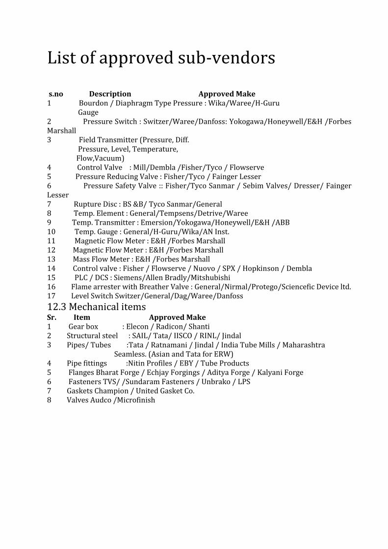
List of approved sub-vendors s.no Description Approved Make 1 Bourdon / Diaphragm Type Pressure : Wika/Waree/H-Guru Gauge 2 Pressure Switch : Switzer/Waree/Danfoss: Yokogawa/Honeywell/E&H /Forbes Marshall 3 Field Transmitter (Pressure, Diff. Pressure, Level, Temperature, Flow,Vacuum) 4 Control Valve : Mill/Dembla /Fisher/Tyco / Flowserve 5 Pressure Reducing Valve : Fisher/Tyco / Fainger Lesser 6 Pressure Safety Valve :: Fisher/Tyco Sanmar / Sebim Valves/ Dresser/ Fainger Lesser 7 Rupture Disc : BS &B/ Tyco Sanmar/General 8 Temp. Element : General/Tempsens/Detrive/Waree 9 Temp. Transmitter : Emersion/Yokogawa/Honeywell/E&H /ABB 10 Temp. Gauge : General/H-Guru/Wika/AN Inst. 11 Magnetic Flow Meter : E&H /Forbes Marshall 12 Magnetic Flow Meter : E&H /Forbes Marshall 13 Mass Flow Meter : E&H /Forbes Marshall 14 Control valve : Fisher / Flowserve / Nuovo / SPX / Hopkinson / Dembla 15 PLC / DCS : Siemens/Allen Bradly/Mitshubishi 16 Flame arrester with Breather Valve : General/Nirmal/Protego/Sciencefic Device ltd. 17 Level Switch Switzer/General/Dag/Waree/Danfoss
12.3 Mechanical items Sr. Item Approved Make 1 Gear box : Elecon / Radicon/ Shanti 2 Structural steel : SAIL/ Tata/ IISCO / RINL/ Jindal 3 Pipes/ Tubes :Tata / Ratnamani / Jindal / India Tube Mills / Maharashtra Seamless. (Asian and Tata for ERW) 4 Pipe fittings :Nitin Profiles / EBY / Tube Products 5 Flanges Bharat Forge / Echjay Forgings / Aditya Forge / Kalyani Forge 6 Fasteners TVS/ /Sundaram Fasteners / Unbrako / LPS 7 Gaskets Champion / United Gasket Co. 8 Valves Audco /Microfinish