Tenaris Running Manual 03
28
-
Upload
thomson-smith -
Category
Documents
-
view
360 -
download
12
description
Equipment PreparationSlips and ElevatorsSafety ClampsStrap WrenchesSingle Joint CompensatorStabbing GuidesHandling and Lifting PlugsPower Tongs7 Pre-Running OperationsDriftingPipe Length MeasurementCleaningVisual Inspection of Threads Before Make-upField RepairField Repair on Coated PipesField Repair on Fiber Glass Lining PipesInstallation of Seal-RingsPipes Lifting From Rack to Rig Floor10 RunningOperations on the Rig FloorThread Compound ApplicationRecommended Thread Running CompoundsThread Lock ApplicationStabbingThread EngagementConnection Make-upMake-up Speed13 Running Pipes With Automated RigsMake-up Torque Curve Pattern14 Make-up Acceptance Criteria15 Make-up Rejection Criteria18 Visual Inspection after Make-upTubular Rig Returns19 Connection Break-outInspectionRe-Running20 Running and Pulling Recommendations21 Specific GuidelinesTenaris BlueTMTenaris MSTM, MS28TM, Tenaris ERTM and Tenaris PJDTMSpecial Care for Connections with Seal RingSpecial Care for Connections with Fiber Glass Lining (FGL)Special Care for Connections with Corrosion Barrier (CB)Torque vs. Turns Monitoring SystemTenaris 3SBTM, Tenaris HWTM, and Tenaris ELTM
Transcript of Tenaris Running Manual 03


5 Equipment Preparation
Slips and Elevators
Safety Clamps
Strap Wrenches
Single Joint Compensator
Stabbing Guides
Handling and Lifting Plugs
Power Tongs
7 Pre-Running Operations
Drifting
Pipe Length Measurement
Cleaning
Visual Inspection of Threads Before Make-up
Field Repair
Field Repair on Coated Pipes
Field Repair on Fiber Glass Lining Pipes
Installation of Seal-Rings
Pipes Lifting From Rack to Rig Floor
10 Running
Operations on the Rig Floor
Thread Compound Application
Recommended Thread Running Compounds
Thread Lock Application
Stabbing
Thread Engagement
Connection Make-up
Make-up Speed
13 Running Pipes With Automated Rigs
Make-up Torque Curve Pattern
14 Make-up Acceptance Criteria
15 Make-up Rejection Criteria
18 Visual Inspection after Make-up
Tubular Rig Returns
19 Connection Break-out
Inspection
Re-Running
20 Running and Pulling Recommendations
21 Specific Guidelines
Tenaris BlueTM
Tenaris MSTM, MS28TM, Tenaris ERTM and Tenaris PJDTM
Special Care for Connections with Seal Ring
Special Care for Connections with Fiber Glass Lining (FGL)
Special Care for Connections with Corrosion Barrier (CB)
Torque vs. Turns Monitoring System
Tenaris 3SBTM, Tenaris HWTM, and Tenaris ELTM
Sec
Delta Torque Definition
Index

Running Manual 5
This manual details the recommended practices to aid in the successfulrunning and pulling of the Tenaris family of premium connections. It has beendesigned to provide an insight to avoid the most common causes of pipe andconnection damages resulting from improper planning, incorrect rigoperations, or inappropriate material handling procedures. The followingsections detail the specific practices to be performed in each operation. This isa general manual that must be used together with the specific guidelines ofthe premium connection to be run.
Equipment Preparation
All accessory and backup equipment, such as cross-overs, safetysubs, float equipment and packer assemblies, should be inspectedto ensure they are in proper condition. Since accessories areobtained from several sources, care should be taken to ensurethey were threaded with the correct connection. Only accessoriesthreaded by Tenaris or one of their licensed repair shop facilitiesshould be used.
Slips and Elevators
Either slip or collar type elevators may be used for casing andtubing strings. The inserts of the slips and slip type elevatorsmust be clean and sharp. Extra long slips and slip type elevatorsshall be used on long and/or heavy strings. lf collar-type elevatorsare used, the bearing surface shall be carefully inspected to ensure a smooth flat bearing contact perpendicular to the pullingdirection. An uneven bearing surface can damage the couplingand lead to a premature connection failure. Spider and elevatorslips shall be examined to see that all the surfaces contact the pipe evenly. Uneven contact can dent the pipe or cause excessslip-cutting.
The use of high-density inserts is recommended for criticalservice materials.
Safety Clamps
The safety clamp is used to suspend the column in case ofinsufficient grip by the elevator. The safety clamp must be used
during the running of the first tubing and casingconnections and during the pulling out of the last tubingand casing connection. Its condition should be inspected and worn parts replaced at the beginning ofeach operation.
Strap Wrenches
When making up corrosion resistant alloys (CRA) pipes, strap wrenches should be used after stabbing tomake the pin up to the hand tight position or atminimum until a secure thread start has been achieved.All straps should be checked prior to start-up to ensuretheir proper diameter capability and their cleanness.Once straps become soiled and begin slipping, theyshould be replaced.
Single Joint Compensator
A single joint compensator is recommended to be usedduring running and pulling of heavy wall casing and anyCRA tubulars to reduce the compression loads on thethreads that are normally incurred during the stabbing,make-up and pull out process.
Care must be taken to properly adjust the tension valueof this component prior to the first joint being stabbed.This will minimize cross-thread damages and gallingduring the make-up and break out process.

6 Running Manual
Stabbing Guides
Stabbing guides shall be used to guide the pin into the box andminimize damage to the connection if the joint is misstabbed.The stabbing guide must be checked prior to running to ensureproper fit and condition of the elastomeric inserts.
Handling and Lifting Plugs
Handling plugs are not designed to support more than a singlestand of pipe. Handling plug threads must be cared for andmaintained. Threads should be cleaned, inspected and handledso as to prevent damage. To ensure proper thread engagement,both the handling plug and the pipe box threads should be freeof any dirt, paint, and storage compound. Plugs should bedoped and fully made-up by hand, then tightened by pushing itwith a bar. Handling plugs also provide protection of the boxthreads from damage by tools or test equipment, which may berun inside the pipe.
Lifting plugs are designed to support the entire weight of thestring. The lifting plugs must be doped and fully made-up andpower tight to shoulder to achieve full rated lift capacity. Properhandling practices and sound judgement must be used at alltimes to maintain the rated lift capacity of the plug. Damagedlifting plugs should not be used. At the beginning of each
operation, as well as in case of heavy impact in the lifting plugthroughout the operation, the lifting plug must be inspectedvisually and replaced in case of damage.
Power Tongs
The tongs should be in good condition, with jaws thatcorrectly fit the pipe.
It is recommended to use tongs with back-up. Tongs shall beequipped with a rotation speed control and should de capable ofoperating at a minimum of 3 rpm. It is imperative that the make-up torque is accurately measured and controlled. Torquemeasuring equipment should be in good working order, cover theappropriate range, and a recent calibration certificate should bedemanded from the power tong contractor prior to starting the job.
When using tongs with built-in back-up, free motion shouldbe possible between tong and back-up to ensure there issufficient travel in the back-up to absorb the make-up loss and there is sufficient flexibility in the tong/back-up tocompensate for a slight bend and the normal eccentricitybetween pin and box.
If a snub line is used, it should be set at a 90-degree angle tothe arm of the tong.
Power Tong - upper view Load Cell Installation - side view

Running Manual 7
Drifting
It is requested that each length of the tubulars (casing, tubing,accessories) be drifted for its entire length just before running.
Before drifting, make sure that the internal surface is clean andfree from foreign matter that can prevent the correct running of the drift and can be mixed with make-up compound duringassembly.
If compressed air is available, apply the air jet from box to pin.
The drift shall be handled with care when inserted and whenextracted from the pipe, and drifting should be preferablyperformed from the box side to the pin side to avoid damageon threads, seals and shoulders.
It is recommended to perform drifting while the pipe is onthe rack.
Tubulars that do not pass the drift mandrel shall bemarked with a reject paint band, and laid aside for furtherinvestigation.
For CRA and coated material, it is recommended to use non-metallic drift or a drift coated with plastic or with Teflon.
Make sure that the drift mandrel OD conforms to the API 5CTspecifications or to the customer’s special drift purchasespecification.
When specified by the purchaser, casing can be "Special Drifted".Sizes are shown in API RP 5A5 "Recommended Practice forThread Inspection of new Casing, Tubing and Plain End DrillPipe", or special drift purchase specifications.
Pre-running Operations
in. mm. in. mm.
Casing and Liners
Tubing
Smaller than 9 5/8” 6 152 d - 1/8 d - 3.189 5/8” to 13 3/8” 12 305 d - 5/32 d - 3.97Larger than 13 3/8” 12 305 d - 3/16 d - 4.76
27/8” and smaller 42 1,067 d - 3/32 d - 2.383 1/2” and larger 42 1,067 d - 1/8 d - 3.18
API STANDARD DRIFT MANDREL SIZE (MIN.)
d= Nominal pipe body internal diameter
PRODUCTS & SIZES (Ø”) LENGTH DIAMETER

8 Running Manual
Cleaning
It is essential that no hard foreign matter is present on thethreads or seals during make-up.
Cleaning should be performed just before running in the holeand after drift test, especially in corrosive atmosphere.
Remove thread protectors from pin and box ends.
Clean all thread or storage compounds with any suitablecleaning process, such as non-metallic bristle brushes and hotwater or a quick-drying solvent-type cleaner (without chlorine).Do not use diesel or "oily solvent". Use of compressed air isadvisable to dry pin and box.
Check and clean inside the tubulars to eliminate any foreignmaterial that may fall into the box while stabbing. Ifcompressed air is available, apply the air jet from box to pin.
The most desirable approach would be to clean the connectionat a temperature above 10°C (50°F) so as to remove all traces ofmoisture and/or extraneous matter.
Clean and dry thread protectors.
If running is to be delayed, an application of some corrosionprotection over the threads should be considered. If theconnection is cleaned until twelve hours before the joint is run,a light oil should be applied by means of a brush or a sprayapplicator. If it takes more than twelve hours for a joint to berun, some storage compound and clean thread protectorsshould be re-applied.
Care must be taken to ensure that the cleaning process doesnot cause environmental pollution.
Pipe Length Measurement
The length of each piece of casing and tubing should bemeasured prior to running. A calibrated steel tape should be used. The measurement should be made from theoutermost face of the coupling or box to the outermost face of the pin nose.
The Effective Length (EL) of each joint is the Total Length(TL) minus the Make-up loss (ML).
Before the make-up on the rig floor, all threads will be submittedto visual inspection.
Pipe should be on a rack allowing enough space for 360°revolution for inspection to assure that each connection is:
• Well cleaned• Free from rust due to a long and/or incorrect storage• Free from handling damages• Free from longitudinal cuts and scratches in the seal area• Free from burrs or wear
Minor anomalies on thread and torque shoulder surfaces canbe field repaired. Damage on seal surfaces, other than mildoxidation, is cause for rejection (see Field Repair). After repairing,threads must be re-cleaned and dried.
Exposed seal surfaces, such as pin nose areas, are particularlysusceptible to handling damage. Special care should be takenin inspection of these areas for dings, dents, and/or mashedends.
Visual Inspection of ThreadsBefore Make-up
Running Manual 9
Field Repair
If necessary, slight thread repairs by # 400 emery cloth or file,can be performed by Tenaris personnel or by certified personnelof a thir party company.
Slight repairs can be made only on the thread or on the shoulderarea, but not on the seal area. Only mild oxidation is allowed tobe removed from the seal by means of a Scotch Brite.
Repairs must not change the shape of the original surface.
When the damages cannot be solved by field repair, the joint must be rejected.
Field Repair on Coated Pipes
Any damage on the coatings must be repaired either by thecoating company or by certified personnel of a third partycompany.
Field Repair on Fiber Glass Lined Pipes
When tubulars with fiber glass lining are to be run, no damagesare allowed to be field repaired.
Installation of Seal Rings
If required by the customer, seal rings can be installed in the millprior to application of thread compound and protectors.Otherwise, seal rings must be securely packaged and forwarded to a location designated by the customer.
Prior to installation, seal rings identification shall be verified.Appropriate seal rings shall be obtained through the TenarisLicensee Support Group.
Visually inspect the seal ring groove/location for cleanliness.Remove all grease, oil, metal shavings, or other contaminantsbefore the installation of a seal ring. Dry the seal ringgroove/location before installing the seal ring.
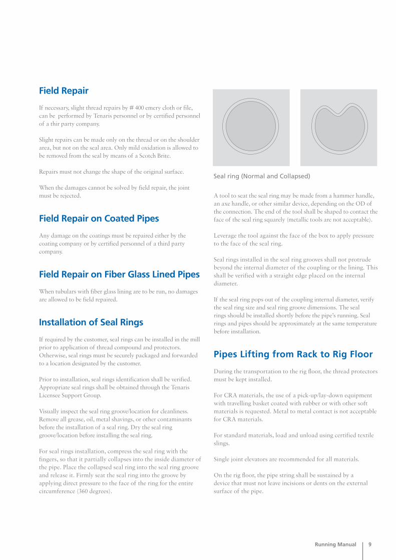
For seal rings installation, compress the seal ring with thefingers, so that it partially collapses into the inside diameter ofthe pipe. Place the collapsed seal ring into the seal ring grooveand release it. Firmly seat the seal ring into the groove byapplying direct pressure to the face of the ring for the entirecircumference (360 degrees).
A tool to seat the seal ring may be made from a hammer handle,an axe handle, or other similar device, depending on the OD ofthe connection. The end of the tool shall be shaped to contact theface of the seal ring squarely (metallic tools are not acceptable).
Leverage the tool against the face of the box to apply pressureto the face of the seal ring.
Seal rings installed in the seal ring grooves shall not protrudebeyond the internal diameter of the coupling or the lining. Thisshall be verified with a straight edge placed on the internaldiameter.
If the seal ring pops out of the coupling internal diameter, verifythe seal ring size and seal ring groove dimensions. The seal rings should be installed shortly before the pipe’s running. Sealrings and pipes should be approximately at the same temperaturebefore installation.
Pipes Lifting from Rack to Rig Floor
During the transportation to the rig floor, the thread protectorsmust be kept installed.
For CRA materials, the use of a pick-up/lay-down equipmentwith travelling basket coated with rubber or with other softmaterials is requested. Metal to metal contact is not acceptablefor CRA materials.
For standard materials, load and unload using certified textileslings.
Single joint elevators are recommended for all materials.
On the rig floor, the pipe string shall be sustained by a device that must not leave incisions or dents on the externalsurface of the pipe.
Seal ring (Normal and Collapsed)

10 Running Manual
Operations on the Rig Floor
While the pipe is in the travel basket or laid on the "V" door,remove the thread protector of the box/coupling, wipe with aclean cloth the box/coupling or blow it with a jet of compressedair and apply the proper amount of thread compound as perpipe manufacturer recommendations.
While the pin is lifted up in vertical position, remove theprotector and wipe the thread with a jet of compressed air.
Inspect the thread to assure that it has not been damaged and it has been properly cleaned.
Apply the correct amount and type of thread compound as perthe pipe manufacturer recommendations.
Stab the pin into the box of the previous pipe, make them upand run them into the hole.
Thread Compound Application
Thread storage compound shall be thoroughly removed fromthe connection before applying running thread compound.
Apply an even coat of manufacturer recommendedconnection thread compound (see Recommended ThreadRunning Compounds) filling the full thread area andcovering the seal surface and torque shoulder of pin or box(as per connection manufacturer recommendation). Donot overdope, the thread pattern should still be evidentafter doping.
Running

Running Manual 11
Keep the dope well mixed, and stir it very well before using. If thecompound is too thick because of the low external temperature, itcan be warmed up to a maximum of 30°C and mixed up. Neveruse oil or solvent to dilute the thread compound.
Keep the dope container covered in order to avoidcontamination from dust, water, or other dangerous elements.
Use new brushes with clean and soft bristle; never use metallicbrushes or spatulas. Use mustache type brush for box end andplain type bruch for pin end.
Apply thread compound in a continuous film all over thesurface of threads and seals as per the connection manufacturerrecommendations.
When automatic dope applicator is used, try to check thedope weight sprayed by collecting it and putting it on a scale. Set up the dope applicator until the minimum weight isreached. When a brush is used, weigh the minimum requested quantity of dope with a scale, to have an idea ofthe dope volume. Special care should be taken to make sure
that quantity of dope does not exceed the maximum specified. Excessive thread dope may affect the connectionperformance.
Thread Lock Application
When thread lock is required, both pin and box connectionsmust be cleaned, dried, and free of contaminants. Apply threadlock compound only on the first two thirds of the pin threadsnear the pipe end, excluding the seal area of the pin. A uniformcoat should be applied, a full 360 degrees.
Then, apply thread compound to the internal seal of the box,covering 360 degrees. The connection shall be made-up assoon as possible after the thread lock and thread compoundhave been applied. A torque in excess of the maximum make-up torque may be required to shoulder the connections.
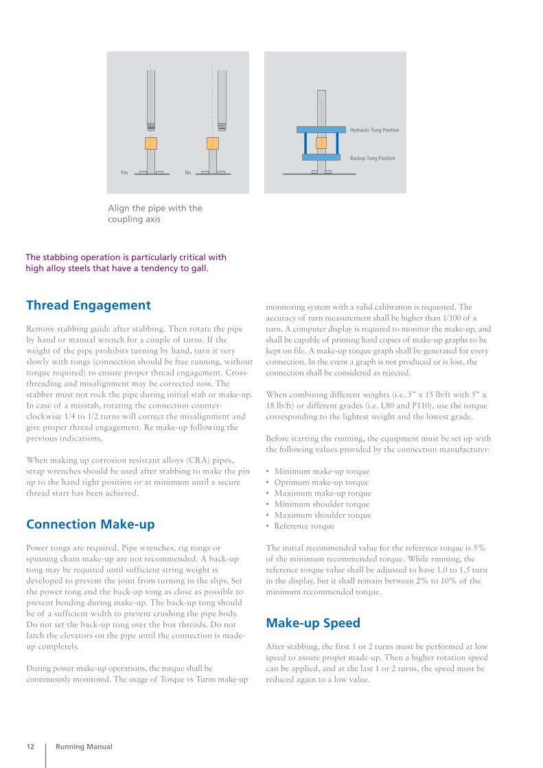
Stabbing
Stabbing and initial thread engagement is the most criticalaspect of running premium connections. A stabbing guide shallbe used on the pipe box thread to prevent damage to thread andseal surfaces. The pipe must be properly positioned and undercomplete control before stabbing is conducted. The pipe mustbe in true vertical alignment over the box. Movement or sway ofthe pipe should be limited to the minimum extent possible.
Personnel on the rig floor and the stabbing board should alwayscontrol stability and movement of the pipe. Only after the pipe is stabilized and properly positioned, lower the pipe slowlyto avoid thread damage. Once the face of the pin is even withthe face of the box, the pin connection should be lowered veryslowly into the box. This process will allow the stab flank ofthe pin threads to align with the flank threads of the box andreduce the possibility of misstabbing, or cross threading.
Recommended Thread RunningCompounds
API Modified Any certified API modified Thread
Thread Compound Compound
Environmentally Safe Jet-Lube-Enviro-Safe
Best-O-Life PTC
Total Premium Compound
Shell Malleus 0459
TYPE APPROVED TRADE MARK
RUNNING THREAD COMPOUND*
*For other running thread compounds, please consult us.
12 Running Manual
Thread Engagement
Remove stabbing guide after stabbing. Then rotate the pipeby hand or manual wrench for a couple of turns. If theweight of the pipe prohibits turning by hand, turn it veryslowly with tongs (connection should be free running, withouttorque required) to ensure proper thread engagement. Cross-threading and misalignment may be corrected now. Thestabber must not rock the pipe during initial stab or make-up.In case of a misstab, rotating the connection counter-clockwise 1/4 to 1/2 turns will correct the misalignment andgive proper thread engagement. Re make-up following theprevious indications.
When making up corrosion resistant alloys (CRA) pipes,strap wrenches should be used after stabbing to make the pinup to the hand tight position or at minimum until a securethread start has been achieved.
Connection Make-up
Power tongs are required. Pipe wrenches, rig tongs orspinning chain make-up are not recommended. A back-uptong may be required until sufficient string weight isdeveloped to prevent the joint from turning in the slips. Setthe power tong and the back-up tong as close as possible toprevent bending during make-up. The back-up tong shouldbe of a sufficient width to prevent crushing the pipe body. Do not set the back-up tong over the box threads. Do notlatch the elevators on the pipe until the connection is made-up completely.
During power make-up operations, the torque shall becontinuously monitored. The usage of Torque vs Turns make-up
monitoring system with a valid calibration is requested. Theaccuracy of turn measurement shall be higher than 1/100 of aturn. A computer display is required to monitor the make-up, andshall be capable of printing hard copies of make-up graphs to bekept on file. A make-up torque graph shall be generated for everyconnection. In the event a graph is not produced or is lost, theconnection shall be considered as rejected.
When combining different weights (i.e. 5” x 15 lb/ft with 5” x18 lb/ft) or different grades (i.e. L80 and P110), use the torquecorresponding to the lightest weight and the lowest grade.
Before starting the running, the equipment must be set up withthe following values provided by the connection manufacturer:
• Minimum make-up torque• Optimum make-up torque• Maximum make-up torque• Minimum shoulder torque• Maximum shoulder torque• Reference torque
The initial recommended value for the reference torque is 5%of the minimum recommended torque. While running, thereference torque value shall be adjusted to have 1.0 to 1.5 turnin the display, but it shall remain between 2% to 10% of theminimum recommended torque.
Make-up Speed
After stabbing, the first 1 or 2 turns must be performed at lowspeed to assure proper made-up. Then a higher rotation speedcan be applied, and at the last 1 or 2 turns, the speed must bereduced again to a low value.
The stabbing operation is particularly critical withhigh alloy steels that have a tendency to gall.
Align the pipe with thecoupling axis

Running Manual 13
When the strings are run by means of automated rigs, therunning procedure varies due to the lack of peopleoperating around the rotary area. Tongs are remotelyoperated from a safe distance from the working area.
Besides the pre-running operations (thread cleaning,drifting, visual inspection, seal ring installation, pipe lengthmeasurement), the thread compound (or thread lock) mustbe applied while joints are on the racks.
After that, the arm of the automatic equipment will pick each joint up and it will deposit them on the tray to be transported to the rotary area.
There is no need for performing any manual operationfrom this point, as the officer in charge of driving theautomatic equipment will position the pipe in a verticalway and will make-up the connection according to thedesired rotary speed and torque value.
Make-up Torque Curve Pattern
Running Pipes withAutomated Rigs

14 Running Manual
The make-up shall be accepted whenever the curve resulting fromthe make-up operation adjusts to the patterns shown below:
Slight oscilations in thread interference length are acceptable.
Make-upAcceptance Criteria

Running Manual 15
If the minimum specified make-up torque is not reached,or the maximum specified make-up torque is exceeded, thethe connection shall be broken out, cleaned, inspected andif it is not damaged, redoped and re-madeup.
Make-upRejection Criteria
Torque Shoulder not Defined
There is high thread/seal interference before shoulders getin touch.
Possible reasons• Misalignment between pin and box• Threads not clean• Wrong torque• Not enough thread compound• Torque cell not properly calibrated
Consequences• Risk of leaking• Risk of accidental unscrewing
The connection shall be broken out, cleaned, inspected,and if it is not damaged, redoped and re-madeup.
Make-up Torque Under Minimumor Over Maximum Specified Value

16 Running Manual
This may happen when the final torque exceeds the connection yield torque.
The connection shall be broken out and the pin and boxconnection shall be rejected and marked accordingly.
Connection’s Plastic Deformation
There is low or high thread/seal interference.
Possible reasons • Wrong torque • Wrong thread compound• Torque cell not properly calibrated
Consequences• Risk of leaking• Risk of accidental unscrewing
The connection shall be broken out, cleaned, inspected,and if there is no damage, redoped and re-madeup.
Torque Shoulder Below or Abovethe Specified Window
Make-up process shall not be interrupted before reachingthe minimum make-up torque value.
The connection shall be broken out, cleaned, inspected, andif there is no damage, redoped and re-madeup.
Aborted Make-up

Running Manual 17
If the maximum hump torque is higher than the maximumshoulder torque, the connection shall be broken out, cleaned,inspected and if it is not damaged, redoped and remade-up.
Possible cause: excessive dope amount or dope contamination. Possible cause: galling or crossthread.
Possible reasons• Non-suitable dies on tong or backup• Dirty or worn dies• Hydraulic pressure in backup too low
Possible consequences• Damage on pipe body• Wrong diagrams even with correct make-up
The connection shall be broken out, cleaned, inspected, andif there is no damage, redoped and re-madeup.
Severe Deviations Prior toShouldering
Tong or Backup Dies Slipping onPipe Body
Possible cause: dies slipping.
General NoteConnections that do not produce an acceptable
graph within three make-ups shall be rejected
and identified accordingly. Connections that show
visible damage and that can not be field repaired
shall be rejected and identified accordingly.

18 Running Manual
Subsequent to each make-up, the area of the pipe/coupling thatwas gripped by the power tongs/back-up device, as well as the sliparea, shall be visually inspected to determine if the pipe/couplinghas been damaged. lf there are excessive tong gouges on eitherthe pipe or couplings, the gouges shall be evaluated in accordancewith API Spec 5CT (see table).
Visual Inspection after Make-up
On those pipes that are not used or returned to stock, all con-nections should be washed and dried to remove any corrosivecontaminants, then greased and clean protectors installed.
No connections should be left witohut storage dope and protec-tors installed.
Pipes’ stock should be periodically inspected every 6-8 monthsin places with gentle weather and more often in places with ex-treme weather conditions.
Tubular Rig Returns
in. in.mm. mm. in. mm.
DIAMETER G1, G2 (EXCEPT C90 AND T95) & G3 G2 (C90 AND T95) & G4
Tubing
Casing
Smaller than 3 1/2” 0.030 0.76 0.025 0.64 0.030 0.763 1/2” to 4 1/2" 0.045 1.14 0.030 0.76 0.035 0.89Smaller than 6 5/8” 0.035 0.89 0.030 0.76 0.030 0.76
6 5/8” to 7 5/8” 0.045 1.14 0.040 1.02 0.035 0.89Larger than 7 5/8” 0.060 1.52 0.040 1.02 0.035 0.89
PERMISSIBLE DEPTH OF IMPERFECTIONS IN COUPLINGS (API 5CT)
PITS AND ROUNDEDMARKS
PRODUCTS & SIZES GRIP MARKS ANDSHARP PATTERN
ALL
G1: All casing and tubing in Grades H, J, K and N.G2: All casing and tubing in Grades C, L, M and T.G3: All casing and tubing in Grade P.G4: All casing in Grade Q.

Running Manual 19
To break out the Tenaris family of premium connections, thesame equipment used to make them up will be required.
If string has been in service for some time, the break-outtorque will likely be higher than the torque required to make-up the connections.
For coupled connections, the back-up tong should always beset on the coupling central area during breaking-out, so it isnecessary to prepare the back-up tong die for the coupling size.Hammering the cupling or connection is not allowed.
Connection Break-out
All connections should be broken out and rotated out in lowgear only.
To break-out the connections, unlatch the elevators beforebreakout. Locate the connection to be broken out at acomfortable working height above the slips. Set the powertong and the backup tong or slips as close as possible toprevent bending during breakout. Maintain verticalalignment and control of pipe. This is accomplished by a manon the stabbing board. Slowly apply the torque required tobreak the connection. (Never use a hammer or other hardobject to beat on a connection. The resultant damage couldlead to a failure.) Depending on the torque required, theupper end of the pipe may start moving. Pipe movement shall
be stopped before additional turning of the connection iscontinued.
Maintain a steady, controlled speed until the pin jumps insidethe box. A single joint elevator is recommended to reducemisalignment during the lifting process. A weight compensatoris recommended to be used to reduce thread galling duringbreak-out.
Stop rotation immediately when the pin jumps inside the box.A stabbing guide shall be used prior to lifting the pin out ofthe box. The pin must be carefully lifted out of the box toavoid damage. This is critical on heavy weight pipe or whenpulling double or triple stands. Remove the power tong beforelifting the pin out of the box. Do not lift the exposed pinthreads through the tong. Before moving the pipe further,protect the threads by installing a clean, dry thread protectoror lift plug as appropriate.
For flush connections, the use of safety clamps is highlyrecommended.
Inspection
Once the connection is broken, a brief inspection of seal andthreads of both pin and box should be conducted.
Particular attention must be paid to:
• Seals for evidence of galling;• Threads for evidence of galling;• Pipe for damage caused by power tong or back-up tong dies;• Pipe for damage caused by elevator or slip dies;• Any foreign material in the threads or in the torque
shoulder/seal area of the box member.
Re-Running
To re-run a string of Tenaris Premium Connections, the sameprocedure as in the initial running should be followed.

20 Running Manual
Running
• Remove thread protectors from pin and coupling ends. • Clean the connection with a non-metallic bristle brush
and steam or a quick drying solvent type cleaner (without chlorine).
• Clean and dry thread protectors. Reject damaged protectors.
• Make sure that the internal surface of the pipes is clean and free from foreign material.
• Check and clean (by air jet) inside the tubulars to eliminate any foreign material.
• Pass drift from the coupling or box end to the pin end avoiding damages on threads and shoulders.
• Tubulars that do not pass the drift mandrel shall be marked with a reject paint band and laid aside.
• For CRA and coated material, use a non-metallic drift or a drift coated with plastic or Teflon.
• Measure the Total Length of each piece of casing / tubing / accessory.
• Calculate the Effective Length of each joint by deducting the Make-up Loss from the Total Length.
• Visually inspect the connection to assure they are:
- Free from dust due to a long and/or incorrect storage;
- Free from handling and transport damages;- Free from burrs or wear.
• Never attempt to repair the seal area of the connections.• Slight repairs can be made by # 400 emery cloth or file
only on the threads or on the shoulder area.• After repairing, threads must be cleaned again and dried. • During pipe moving to the rig floor, thread protectors
must be kept installed.• Use of weight compensator system is requested, specially
in the case of CRA grades.
Pulling
• Use of weight compensator system is requested, specially in the case of CRA grades.
• For coupled connections break-out, the back-up tong shall be set on the coupling middle position.
• The break-out torque will likely be higher than the torque required to make up the connections.
• All connections should be broken out and rotated out in low gear only.
• Never use a hammer or other hard object to beat on a connection.
• Maintain a steady, controlled speed until the pin jumps insidethe coupling (avoid bumping).
• Stop rotation immediately when the pin jumps inside the coupling.
• A stabbing guide shall be used prior to lifting the pin out ofthe coupling.
• The pin must be carefully lifted out of the box avoiding to damage it.
• Before moving the pipe further, protect the threads by installing a clean and dry thread protector.
• Once the connection is broken out, a brief visual inspectionof both pin and coupling should be conducted. Particular attention must be paid to:
- Threads for evidence of galling;- Pipe body for damages caused by power tong,
backup tong, elevator or slip dies;- Any foreign material in the threads or in the
torque shoulder of the coupling.
• If the string is pulled out in stands, pin thread protectors should be on straight and tight.
• Stands should be properly tied with a band to prevent bending.
Running and Pulling General Recommendations - Summary
Note: this section does not replace the Tenaris Running Manual.It shall be used together with it.
Running Manual 21
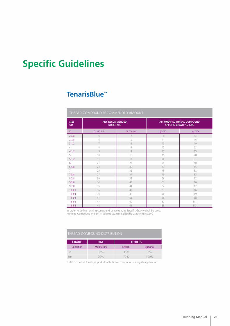
TenarisBlue™
Specific Guidelines
cu. cm max.cu. cm min.in. gr min. gr max.
SIZEOD
ANY RECOMMENDED DOPE TYPE
API MODIFIED THREAD COMPOUNDSPECIFIC GRAVITY = 1,85
2 3/82 7/83 1/244 1/255 1/266 5/877 5/88 5/89 5/89 7/810 3/810 3/411 3/413 3/813 5/8
5 7 9 136 9 11 167 11 13 198 12 15 229 14 17 25
10 15 19 2811 17 20 3121 27 39 5023 30 43 5525 32 45 5827 34 49 6330 39 56 7234 43 62 8035 44 64 8236 47 67 8638 48 70 8941 53 76 9847 60 87 11148 61 88 113
THREAD COMPOUND RECOMMENDED AMOUNT
In order to define running compound by weight, its Specific Gravity shall be used:Running Compound Weight = Volume (cu.cm) x Specific Gravity (gr/cu.cm)
THREAD COMPOUND DISTRIBUTION
GRADE CRA OTHERS
Pin 30% 30% 0%
Box 70% 70% 100%
Note: Do not fill the dope pocket with thread compound during its application.
Condition Mandatory Recom. Optional
22 Running Manual
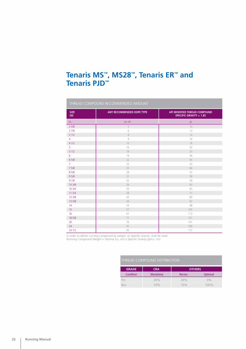
Tenaris MS™, MS28™, Tenaris ER™ andTenaris PJD™
SIZEOD
ANY RECOMMENDED DOPE TYPE API MODIFIED THREAD COMPOUNDSPECIFIC GRAVITY = 1.85
THREAD COMPOUND RECOMMENDED AMOUNT
In order to define running compound by weight, its Specific Gravity shall be used:Running Compound Weight = Volume (cu. cm) x Specific Gravity (gr/cu. cm)
in. cu. cm gr
2 3/8 5 102 7/8 6 123 1/2 8 144 9 164 1/2 10 185 16 305 1/2 18 336 19 366 5/8 22 407 23 427 5/8 25 468 5/8 28 529 5/8 31 589 7/8 32 5910 3/8 34 6210 3/4 35 6511 3/4 38 7113 3/8 43 8013 5/8 44 8214 53 9815 57 10516 61 11218 5/8 71 13120 76 14124 91 16924 1/2 93 172
THREAD COMPOUND DISTRIBUTION
GRADE CRA OTHERS
Pin 30% 30% 0%
Box 70% 70% 100%
Condition Mandatory Recom. Optional
Running Manual 23
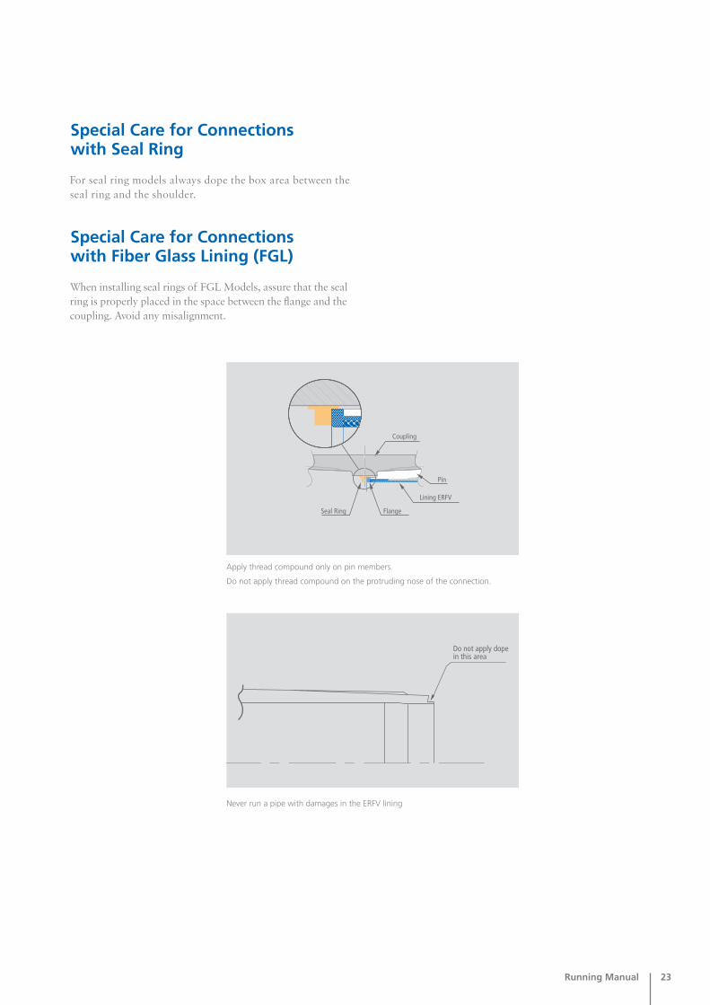
For seal ring models always dope the box area between theseal ring and the shoulder.
Apply thread compound only on pin members.
Do not apply thread compound on the protruding nose of the connection.
Never run a pipe with damages in the ERFV lining
Special Care for Connectionswith Seal Ring
When installing seal rings of FGL Models, assure that the sealring is properly placed in the space between the flange and thecoupling. Avoid any misalignment.
Special Care for Connectionswith Fiber Glass Lining (FGL)

24 Running Manual
Note: Thread compound could be used to cover the seal areainstead of Molykote, in this case a thin, uniform film coveringthe seal along the circumference (360°) should be applied. Avoiddoping the small protruding nose outside Part B.
In this case each made up connection must be checked with a “Teflon drift” to verify the seal ring has not been damagedduring make up.
If pipe or coupling coated area is damaged, it must be repairedbefore running the string. This activity can be performed by the coating company or by authorized and certified personnelof a third part company.
Torque vs. Turns Monitoring System
For the making up of the Tenaris ER connection the use of aTorque vs. Turns Monitoring System is not required.
Use Shell HTHP 72732 thread compound for make up. Theuse of compound with different properties may result in low or over torque of the connection, galling and/or leaking.
Environmental friendly compounds may be used with Tenarisapproval.
Apply thread compound only on pin members.
The use of Molykote (Molybdenum disulphide) is recommendedto cover the seal area (Part B). Use the recommended threadcompound to cover the threaded area (Part A).
Special Care for Connectionswith Corrosion Barrier (CB)

Running Manual 25
Tenaris 3SB™, Tenaris HW™, andTenaris EL™
In order to define running compound by weight, its Specific Gravity shall be used:Running Compound Weight = Volume (cu. cm) x Specific Gravity (gr/cu. cm)
cu. cmcu. cmin. gr. gr.
SIZE ANY RECOMMENDED DOPE TYPE
API MODIFIED THREAD COMPOUNDSPECIFIC GRAVITY = 1,85
2 3/82 7/83 1/244 1/255 1/266 5/877 5/88 5/89 5/89 7/810 3/810 3/411 3/413 3/8
6 9 12 178 11 14 20
10 14 18 2511 15 20 2812 17 23 3216 24 30 4519 27 35 5022 4024 32 45 6027 32 50 6032 38 60 7038 43 70 8034 49 62 90
54 10043 8054 10065 70 120 130
THREAD COMPOUND RECOMMENDED AMOUNT
TENARIS 3SBTMOD TENARIS HWTM
cu. cm
TENARIS ELTM TENARIS 3SBTM TENARIS HWTM
gr.
TENARIS ELTM
THREAD COMPOUND DISTRIBUTION
GRADE CRA OTHERS
Pin 30% 30% 0%
Box 70% 70% 100%
Note: Special care shall be taken to not over-dope the connection. Over-doping canlead to excessive dope pressure built up and abnormal Torque vs. Turns curves.
Condition Mandatory Recom. Optional

26 Running Manual
Tenaris makes available this Manual for informational purposes only and in no way assumes responsibility or liability for anyloss, damage, or injury resulting from the use of information and data herein. The technical information contained hereinshould not be construed as a recommendation. Although reasonable efforts have been made to maintain the accuracy andreliability of its content you should only rely on its conclusions at your own risk. You should not rely on descriptive productdata or other information in this Manual without professional engineering advice.
Sec
THREAD COMPOUND DISTRIBUTION
GRADE CRA OTHERS
Pin 30% 30% 0%
Box 70% 70% 100%
Note: Special care shall be taken to not over-dope the connection. Over-doping canlead to excessive dope pressure built up and abnormal Torque vs. Turns curves.
Condition Mandatory Recom. Optional
cu. cm max.cu. cm min.in. gr min. gr max.
SIZEOD
ANY RECOMMENDED DOPE TYPE
API MODIFIED THREAD COMPOUNDSPECIFIC GRAVITY = 1,85
2 3/82 7/83 1/244 1/255 1/266 5/877 5/88 5/89 5/89 7/810 3/810 3/411 3/413 3/813 5/8
10 14 18 26 11 17 21 32 14 21 26 39 16 24 30 44 18 27 33 50 25 35 46 65 28 38 51 71 30 42 56 78 33 46 61 86 35 49 65 91 38 54 71 99 43 61 80 112 48 68 9 125 49 69 91 128 52 72 96 134 54 75 99 139 59 82 109 152 67 94 124 173 68 95 126 176
THREAD COMPOUND RECOMMENDED AMOUNT
In order to define running compound by weight, its Specific Gravity shall be used:Running Compound Weight = Volume (cu. cm) x Specific Gravity (gr/cu. cm)
Delta Torque % = x 100Final Torque – Shoulder TorqueFinal Torque
Delta Torque Definition