
Tenant Fit-out Manual For TenantsThe Manual is intended to provide criteria, which is the...
48
Tenant Fit-out Manual For Tenants
Transcript of Tenant Fit-out Manual For TenantsThe Manual is intended to provide criteria, which is the...

Tenant Fit-out ManualFor Tenants
32
Table of Content
1 Introduction to Interior Fit-out Manual
2 Programme
3 Visual Themes and Finishes of Landlord Areas
4 Tenant Fit-out Specifications
5 Landlord’s Provisions
6 Tenant’s provision
7 Approval Process
8 RAC Tenants Guidelines – Fit-out Manual
9 Landlord Guidance for Retail Tenant Strip-out
10 Appendices
a) Entry/ Exit Request Permit
b) Request for Temporary Security Clearance
c) Safety Additions to the fit-out guidelines
d) Procedures for Contractors Undertaking Airside Works
e) ICT Standards Documents
i. Access Control System Standard ii. ICT Cabling Standards iii. Fire Detection and Alarm System Standard iv. Public Address System Standards v. New Office Network Standards vi. Closed Circuit Television (CCTV) Standard vii. Building Automation System Standard viii. ICT Network - Design and Standards Overview

54
1.0 Introduction to the Interior Fit-out Manual
The tenant is provided with a set of typical drawings referring to their particular unit, which is included in the Tenant/Concession Tender Package. These drawings are available in AutoCAD & PDF format upon request.
In situations where additional requirements may be required during the tenant lease period or at the outset from sources such as the local authority or the fire department, the Landlord will endeavour to inform the lessees at the outset.
Please note that all works carried out by the Tenants contractors will be in accordance with all relevant Constructional Requirements as specified within this document and with the prior approval from Riyadh Airports Company.
Note: Landlord - Refers to Riyadh Airports Company (RAC) / King Khaled International Airport (KKIA)Note: Retail unit - Refers to Retail or Catering units etc.
1.1 The purpose of the Interior Fit–out Manual
This Interior Fit-out Manual is to assist the appointed Designers of the tenant in the preparation of drawings and specifications in order to meet the relevant design criteria set by the landlord, this in turn provides a guide in relation to the standard and quality that is expected in keeping within the regulations and procedures in respect of the design & fit out.
The Manual is intended to provide criteria, which is the responsibility of the tenant, the design team and the appointed contractors to comply with all relevant regulations and code of practice throughout fit-out. This Manual also outlines all security requirements, which have to be obtained, and adhered to as stipulated by Riyadh Airports Company.
The purpose of this Manual is to encourage good design. The intended tenant is required to produce an individual design and character to achieve individual expression from each tenant.
Note to all Tenants, Designers and Contractors
All tenants, consultants and associated contractors are advised to review this document carefully and also take note of all relevant sections, which are affiliated to them. Should you require any further clarification in regard to this Design Fit out Manual all queries should be addressed to the allocated Relationship Manager.
The criteria set forth is intended for use by all tenants, including those who have a nationally or internationally recognisable storefront design.
Whilst the primary aim is to allow maximum expression of a store’s individual style and character, it is the intention of the landlord not only to remain flexible in the review of fit out proposals, but also to achieve a high level of design quality, diversity, and individual expression from each tenant. In this regard it is the landlord’s intent to discourage bland design and ‘facsimile’ type designs and will not adopt a ‘rubber stamp’ approach to proposals. RAC wishes to encourage new and modern design approaches.
RAC reserves the right to amend this Fit Out Manual.
1.2 Tenant Fees and Charges
In relation to the relocation of existing landlord services terminated within the unit, a cost will be incurred for this work by the tenant, for example relocation electrical isolation board. The landlord will endeavour to co-ordinate all new service provisions with the tenant regarding all positions of service locations.
Damage caused by a fit out contractor to landlord areas during the fit out of a tenant unit will be made good by the Tenant / Fit out contractor at his or her cost; this includes the building fabric, structure, internal finishes and roof fabric etc., all the above will be assessed prior to work being undertaken.
1.3 Health & Safety
For information regarding Health and Safety Requirements and Standards, please refer to the “General Safety Requirements and Guidelines” document contained within the Appendi-ces of this document.
for information regarding safety ,health and general safety requirement standard refer to document “Appendix”.
2. Programme
All Tenants must strictly adhere to contract dates in order to achieve programme completion.
3.0 Visual Themes and Finishes of Landlord Areas – for Information ONLY
76
3.1 FloorsFloor finishes should be hardwearing, easily maintainable surface with a suitable non-slip finish.
3.2 Structural SpecificationThe building has been designed to accommodate the maximum imposed loads as stated in the relevant standards.
While it is not envisaged the tenant design will impact or alter any structural members, any additional loads must be reviewed case by case.
3.3 Walls and pilastersWall & Pilasters will be simple, clean surfaces with small areas of bold colour. The surface should be easily repairable rather than cleanable to enable 'softer' finishes. Pilasters should be simple and allow for feature lighting. All areas should be protected at low level by S.S. rails fixed to wall.
3.4 CeilingsThe concept is to provide clean, neutral surfaces that provide a feature over the central area. Lighting should primarily be over the surface of the ceiling with accented edges. Regular lighting spots to cover floor areas should be provided. For Kiosk the optimum ceiling level within each unit is 2.7m.
3.5 RoofsExisting roof is built in accordance with building regulations and also to manufacturer‘s guidelines.
3.6 Tenant SignsProvision and clear visibility should be allowed for over each unit. (See later section)
3.7 LightingFloor finishes should be hardwearing, easily maintainable surface with a suitable non-slip finish.
3.8 Road AccessDelivery access will be available to all tenant contractors under the rules and regulations of RAC. Details of these access routes will be made available prior to the commencement of fit out. The tenant is responsible for obtaining all required security access passes prior to the commencement of the construction programme.
3.9 Escape RoutesAll emergency routes and discharge points throughout the development are provided by tenant with RAC supervision. All routes will be designated as right of way and kept clear at all times.
3.10 Tenant Shop frontSupport for the tenants shop front should be provided at all three edges of the opening. The shop front will not be allowed to encroach beyond the agreed boundary demise. Open fronted stores are encouraged as part of the Fit out Manual.
3.11 Electricity SupplyEach tenant must apply directly to the landlord for an electricity supply. The tenant must comply with all landlord terms and conditions. and the electricity supply will be undertaking and cost borne by the tenant.
3.12 Information and Communication Technology and SystemsFor Information regarding ICT Systems please refer to the ICT Documents contained within the Appendices of this document.
4.0 Tenant Fit-out Specification
4.1 Landlord’s Security & Fire requirementsThe Landlord requires that the Tenant‟s Fit out Contractor complies with all safety, security and aerodrome directives and methods of working as laid down by the Landlord during the construction phase of the Tenant‟s occupation of any Unit.
4.2 Execution of WorksWorks shall be executed in accordance with the RAC Tenant‟s Fit Out Guidelines.
The landlord requires that all tenant Fit Outs must comply with the Landlord‟s Standardisation Document in order to enhance all building Services and Systems by specifying tried, tested and approved equipment.

98
4.3 Coordination with other – Designers, Fit-out Contractors on siteThe Designers and Retail Fit-out Contractors shall co-operate with other Contractors and allow access to the relevant sections in good time to carry out their duties.
The Designers and Fit-out Contractors shall attend coordination meetings, which will be confirmed with the RAC. Also there will be requirement for Progress Meetings on frequent occasions with the Tenant, RAC Team and the Fit-out Contractors.
4.4 Frontage DesignThe objectives of the frontage design criteria are to ensure that the individual designs provide an exciting and vibrant retail offer while, providing clear choice and variety.The frontage is defined as the elements of the unit behind the shutter/ site boundary demise. Consideration should be given to the use of display elements, graphics etc. some of which are illustrated.
Where a column forms part of a frontage, surrounded on either side by the same tenant, this column may be incorporated into the tenant‘s frontage design subject to landlord‘s approval.
Be vigorous in your approach to design, keeping in mind the following:
o Do not disturb or alter the Landlord’s finishes
o Ensure that fixed displays or other fixed elements are positioned toavoid the Landlord’s shutter line/ boundary demise line.
The Tenant is to demonstrate proposals in regard to this for approval
4.5 SignageAll signage should be sympathetic to the surrounding environment and shall require the Landlord / Marketing department approval for concept and for detail prior to manufacture.
4.5.1 GeneralAll signage identification and graphics are subject to approval of RAC.
Imaginative, unusual and non-traditional signs are encouraged within the sign zones.
Face illuminated, fret-cut, halo, edge or externally illuminated letters are acceptable.
Face-illuminated signs will not be acceptable unless the illumination is integrated into the sign body.
Non-internally illuminated signs must be mounted on a support back box to allow the standard fixing.All fascia signs to be suspended from the soffit box, no fixings are to be made through the shutter bulkhead.
Use only factory-finished materials with precise engineering and jointing Trading Name and Site Requirements.
Wording of signs is limited to trading names only and may be placed anywhere on the signage zone. Logos may be included and are subject to review and approval.
In the instance where the frontage width is greater than the standard gridline width, the number of signs permitted will be subject to agreement with the Landlord.
4.6.2 Unacceptable Sign TypesThe following lists sign types, which are not permitted:
o 'Bus stop' or projecting signs should not be used, no signs should obscure other Tenant fascia.
o Advertising slogans, brand names, product names or product brand ladders, details and credit card acceptance signs are not allowed.
o Paper, cardboard Styrofoam, cloth and similar stickers or decals.
o Sign manufacturers or installer‘s decals may not be positioned in public view.

1110
o Any permanent text such as strap lines, brand ladders or mission statements may not appear as a manifestation or in the shop front zone. The only exceptions will be where they form part of a protected brand to Landlord approval
o Any graphics or signs that are not professionally produced.
o Design to avoid the use of vinyl lettering. The Landlord will only accept it in high quality and small proportion where it is agreed that there is not appropriate alternative.
o Animated, flashing, flickering or intermittent lights, black light or strobe lighting or moving or rotating signs.
o Exposed neon signage is not permitted unless incorporated with three- dimensional diffused letters subject to the Landlord‘s approval.
o Blade signs or other projecting signs.
o Mobile signage boards.
o Letter with exposed fastenings and unfinished edges.
o Signs painted directly on the finishes.
4.6.3 Signage Illumination
• Sign illumination in general should be internal and self-contained
• The mechanics of all internal illuminations must be concealed
• All external light fixtures must be glare free.
• Signage lighting must not be hung from nor fixed to the mall ceiling
• Concealed neon and incandescent light sources must be on a rheostat with brightness levels subject to approval
• No exposed wiring, conduits, tubing, crossovers, or raceway will be permitted.
• All conductors, transformers, cabinets, housings and other equipment must be concealed.
4.7 Merchandising displaysThe Tenant role in making the retail vision of the Terminal/ Pier a reality is your individual merchandising expression, which will have a significant effect as whole. We expectrails fixed to wall.
merchandising displays to be designed and to be maintained to a consistent high standard. It is vital that retailers use the display zone to the best effect, ensuring greater visibility of individual retail offers.
The following requirements should be incorporated:
• Innovation
• Bold coherent graphics
• Good use of focal points
• Creative use of shapes
• Innovative lighting – each area leading on to another
• Good use of lateral display walls either side of entrances.
Drawings should be provided and evidence of the merchandising layout. The Landlord will need to be satisfied that the merchandise is well presented and that the initial quality of presentation can be sustained.

1312
4.8 LightingA well-designed Energy Efficient sustainable Lighting System is required to create a distinct mood within the shop to set off the merchandise and create an enticing draw from the mall.
Lighting is fundamental to all design and in particular the Landlord is interested in the effect of the tenant lighting on the overall mall ambience.
It is especially important that the retail lighting respects the Landlord‘s intentions for the mall and does not cause glare or light pollution.
The lighting of the whole of the customer area, signage and display will require the Landlord‘s approval and you will need to demonstrate how you will meet their expectations.
4.8.1 General• Lighting levels should vary throughout the sales area to create liveliness, focal points and mood.
• Shop front and in-shop illumination should be glare-free. All light sources are to be concealed.
• Fluorescent lighting must be either recessed or track type and cannot be within the first two meters of entrance.
• Strobe, spinner and chase type lighting is not acceptable. Exposed fluorescent batten fixtures and incandescent light globes are also not acceptable. High intensity discharge lighting may only be used if approved by the Landlord.
• Exposed neon is not permitted.
• Exposed fittings, other than purely decorative, are not permitted. If exposed fittings are proposed, they must be well designed and enhance the design to the approval of the Landlord.
The quality and intensity of signage lighting will be considered case by case to complement the lighting design for the interior public areas of the Terminal.
4.8.2 Display
• Set piece displays should be lit creatively and artistically.
• All showcases and display cases must be adequately ventilated to accommodate heat gain, from the storefront and display window lighting, as well as sunlight.
• Higher levels of illumination need to be achieved over your merchandise displays. Displays are best lit with low voltage systems i.e. metal halide, quartz or low voltage type lighting.
4.9 MaterialsMaterials and finishes should be of high quality and appropriate to the overall concept of KKIA.
Materials must be attractive and robust.
4.9.1 General
• Mirrored shop fronts, or plain painted plasterboard shop fronts are not permitted. Exposed, unfinished edges should not be visible.
• Any stall riser materials shall be durable, such as stainless steel. Painted plasterboard chipboards or MDF are not appropriate stall risers. If laminated stall risers are proposed, they will require recessed metal edge protection to the approval of the Landlord.
• Abutments of all floor finishes are to be flush finished. Abutment of mall and retailer floor finish is to include a recessed metal edge strip. (Screw fixed edge plates are not acceptable) Ensure movement joints in the floor finish coincide with the construction and expansion joints in the structural slab. All designers should take into account all structural elements and floor expansion joints and implement into their floor finish design
4.10 Design GuidelinesAll building facilities must be designed:
• In compliance with applicable codes and standards
• To meet the power and communications requirements specified for other systems and equipment
• To ensure reliability and durability of systems and components
• To comply with safety and protection measures for people and equipment
• To ensure cost effectiveness
• To ensure efficiency and energy conservation
• To simplify installation, operation and maintenance

1514
4.11 Interior Walls and Partitions• Walls shall be durable and resistant to wear under high usage.
• Walls shall have high resistance to accidental damage and vandalism.
• Hard-surface walls shall be resistant to caustic and scouring cleaning powders and detergents.
• Walls shall be low maintenance, easily cleaned and easily repaired.
4.12 Interior Floors• Floors in public areas shall have a high resistance to deterioration and accidental damage.
• Floors shall have high compression strength to resist impact from footwear and sharp and pointed objects.
• Floors shall have slip-resistance under wet and dry conditions
• Hard-surface floors shall be acid, alkali, salt, and oil resistant on their surfaces andthroughout their depth.
• Hard-surface floors shall be resistant to caustic and scouring cleaning powders and detergents
• Floors shall be low maintenance, easily cleaned and easily repaired.
4.13 Tenant’s CeilingsCeilings shall have high resistance to deterioration and disfigurement due to their interior environment.
1. Ceilings shall have high resistance to accidental damage and vandalism.
2. Ceiling surfaces shall be resistant to caustic and scouring cleaning powders and detergents.
3. Ceilings shall be low maintenance, easily cleaned and easily repaired.
4. Where no ceilings are provided, all exposed surfaces (beams, decking, conduit, etc.) shall be finish painted or factory finished unless noted otherwise.
The ceiling is a major visual element in the overall unit presentation. Each retailer is strongly encouraged to be imaginative in the design of the ceiling and lighting systems.
The ceiling of the whole trading area of the retail unit requires the Landlord‘s approval.
The fascia bulkhead is provided within the Landlord‘s fit-out and can be used to provide support for lighting and displays.
The technical requirements for the ceiling are as follows:
- Ceilings are to be suspended from structural elements only.
- Ceilings may not be neither suspended from mechanical ductwork, cable trays nor hydraulic or fire service pipe work.
- Adequate access over the whole area is required in the ceiling and bulkheads for maintenance and repairs to all equipment located in the ceiling space.
- Solid ceilings under 800mm depth need not be sprinkled in the void, however all ceilings deeper than this will need sprinkler provision to the void.
- Open ceilings should have a free area of at least 75%.
- Ceiling supports to be rigid hangers/ rods and not wire cable.
- All designers are to take into account all points of access within the ceiling areas. These are all to be identified and reviewed with the landlord
- The Landlord will need detailed information on all fire aspects of the ceiling design for approval.
5.0 Landlord’s ProvisionsBuilding Shell – provision of clear space unfinished with services as below. In some developments, the tenant will be required to form the new shell and core clear space for their particular fit-out.
Electricity supply –Refer to existing as-built drawings for information.
Water– In some units, none is provided by Landlord. Refer to existing as-built drawingsfor information. Where service is provided, the tenant may reuse as required.
Ventilation System – Provision of primary ductwork and fan coil units to the retail space for cooling. Tenants may connect flexible ductwork to the units and distribute as required, with some flexibility for the tenant to reposition. Any alterations to the location of the fan coil units, temperature sensors or distribution ductwork to facilitate the fit out will be by the tenant and will have to be agreed in writing with the RAC engineering department.
Fire Alarms – provision of detectors to structural soffit linked back to main airport System.

1716
Emergency Lighting – individual tenant units to install and maintain their own standalone emergency lighting system. Tenant areas located within open plan areas are required to connect into the RAC system.
Sprinklers – provision of sprinkler heads to the ceiling void area as shown on the drawing. Provision of some ceiling level sprinklers. Any alterations to these positions or the need for additional heads will be by the Tenant and subject to approval.
Data points for EPOS –. Additional points can be provided on request and at an extra charge.Access – access is provided to all tenant areas and will be designated by the Landlord.
6.0 Tenant’s provision – to be provided by the tenant at his or her own cost.Finishes – provide all floor, wall and ceiling finishes, merchandising units, displays and alllighting – These should conform to the Tenant‘s Design Guide. Security – provide any internal security or alarm system as required.
Signs – provide all internal signage and external bulkhead signage strictly in accordance with the Tenant‘s Design Guide and to the approval of the Landlord.
Electricity supply – distribution cabling, points and all lighting. Tenant will be liable for all metered consumption.
Water– If none is provided by the Landlord, tenant will have to provide at his/her own cost. Refer to as-built drawings for further information.
Ventilation System – Secondary distribution ductwork, controls and grilles and diffusers, and any changes to suit the Tenant‘s fit-out.
Fire Alarms – install sensors and sounders to positions suited to the Tenant‘s fit-out and to the approval of the Fire Officer.
Emergency Lighting – provide emergency lighting to suit the Tenant‘s fit-out and to the approval of the Fire Officer.
Sprinklers – alteration to existing head positions or the provision of additional heads will be by the Tenant and subject to the approval of the Fire Officer. Design, install and commission of sprinkler system to be carried out by an approved accredited contractor.
Additional Data Points Cabling, CCTV & Cabling – Please refer to the ICT documents contained within the Appendices of this document.
7.0 Approval ProcessAll tenants must approve all shop fitting works with the landlord, in order to facilitate this; the tenant must adhere to the following procedures in order to achieve approval. Please note that the following procedures are based on the current RAC programme as enclosed in this Manual, all-critical dates MUST be adhered to in order to achieve fit out completion. All Tenants area required to submit own fit out programme at conception stage for RAC.
Stage 1 - SubmissionThe tenant is required to submit 6 copies of all fit out drawings as per RAC Tenant Guidelines for initial approval with associated costings regarding the value of the fit out. The tenant designers should clarify this at stage 1 milestone.
Stage 2 - SubmissionSupport for the tenants shop front should be provided at all three edges of the opening. The shop front will not be allowed to encroach beyond the agreed boundary demise. Open fronted stores are encouraged as part of the Fit out Manual.
On the final design stage, the tenant is requested to submit a (6) copies as the following:
Architectural & Structure Package:
Floor plans indicating complete layouts with all associated fixtures & fittings Floor plan schedules – indicating floor finish proposals
Reflective ceiling plans
Internal lavational schedules
Cross sections
Elevations
Shop front sections & details
Signage proposals including Structural Fixings
Perspective views internal & external
Sample / Mood boards indicating intended materials and finishes (and details)
Photographic samples of previous similar fit-outs
Provision of tenant fit-out programme based on landlord‘s fit-out programmeMethod statements concerning shop front installation, delivery to/through landlord areas, protection of landlord finishes

1918
Stage 3Mechanical & Electrical Packages
All plans indicating all proposed M&E layouts
Kitchen ventilation layouts including details
Noise & Vibration figures concerning Ventilation
Duct route drawings with associated supporting details Full M&E technical specification & Control Strategy M&E reflective ceiling layouts
Specification of fire alarm system
Sanitary services – including all details including requirements by landlord Water and drainage services as required
Internal Sprinkler System
Emergency Lighting & fire alarm system
Ceiling void sections with associated fixing details
Method statements regard installation of plant
Loads
Stage 4Safety& fire protection Packages
Submitt a technical drawings related with Safety & fire protection as :1. National Association of the US of protection from fire NFPA
2 - Saudi Code of Fire Protection Code SBC801A
General requirements:
• Fire Fighting Systems (Manual /Automatic)
• Fire alarm systems
• Fire water tanks and pumps
• Capacity and height of roads (for fire engines)
• NFPA 14 STANDARD FOR INATALLATION OF STANDA PIPE & HOSE SYSTEM Class IIIfire hose reel cabinet, with its specifications
• Outlets of fire water outside and inside the building STAND PIPE and FIRE HYDRANT
• Electricity protection rooms and Alkmbiot Rat / use of material: NOVEC1230 andPRE-ACTION SYSTEM
• Kitchen Protection: Fire suppression - wet chemical
• NFPA 10- STANDARD FOR PORTABLE FIRE EXTINGUIHSER
• NFPA 13 STANDARD FOR THE INSTALLATION OF SPRINKLER SYSTEM
• NFPA 96 Ventilation Control and Fire Protection of Commercial Cooking Operations
• NFPA 30 FLAMMABLE LIQUID STORAGE
• NFPA 51 Welding & Cutting
• NFPA 58 LPG
• NFPA 70 Electrical Fire Safety
• NFPA 72 Fire Alarm &Smoke Detectors
• NFPA70E Work Place Electrical Safety
• NFPA 101 Life Safety Codes
• NFPA 101B: Code for Means of Egress for Buildings and Structures 220 CombustibleMaterial Construction
• NFPA 5000 BUILDING CONSTRUCTION AND SAFETY CODE)
Stage 5Security package:
• Fence plan and supplement as standard (if the project on Airfield)
• CCTV
• Guard House

2120
Stage 6Work Permit
When the tenant receives the approval from RAC CEO or assigned designate to start the work, then the tenant shall be issued with the work permit from Maintenance department to start the implementation.
Note: some projects based on nature need government review such (GACA. MOI...etc.), and these will have to be arranged by the Tenant in coordination with KKIA/RAC.
Stage 7
Handover
Once the fit-out works have been completed the tenant is obligated to complete a certificate of handover.
Stage 8
As built Drawings
All drawings are to be provided once the unit is complete. All documentation is to be provided to the Engineering department with the following:
Three sets of all drawing packages and associated specifications
Full digital versions of the above drawings in Auto-Cad and PDF format. All documents should be in word format and also PDF format.
The following documentation is required:
01 Safety Statement
02 Health & Safety Document
03 Commissioning Certificates
04 All Maintenance Documents
8.0 RAC Tenants Guidelines - Fit Out Manual
1 Introduction
2 Presentation
3 Programme & Approval of Fit-Out Contractor
4 Design Submissions
5 Statutory Approvals – Regulations – Licences
6 Site Access
7 Hoardings
8 Staff of Tenant, Contractors, & Sub-Contrcators
9 Codes of Practice
10 Waste
11 Electrical Services
12 Communications Services
13 Mechanical Services
14 Suspended Ceilings
15 Annoyances
16 Hot Works

2322
17 Safety
18 Site Storage & use of Flammable Liquids Gases & Chemicals
19 Chemical spillages
20 Fire Safety
21 Clean Site
22 Damage
23 Security
24 Notification
25 Equipment
26 Quality Procedure
27 Certificate of Compliance
28 Fire orders in the event of a fire
29 Contractors Drivers
30 Contractors Escort Vehicles
31 Airport Authority Contacts
32 Drawings
1 Introduction1.1 These guidelines are to assist Tenants, their architects and fit-out contractors intending to carry out construction work on airport premises with regard to procedures, approvals and regulations.
1.2 RAC shall be referred to as the landlord.
1.3 The Tenants attention is drawn to the Landlords requirements that the Tenant, his architect and fit-out contractors must fully acquaint themselves with and comply with the regulations contained within these guidelines prior to fit-out work commencing on site.
2 Presentation2.1 The Tenant must submit at an early stage of the project to the Landlord‘s representative sketch designs comprising plans, elevations and visuals, together with signage proposals. A statement of materials to be used should also be submitted at this stage.
2.2 It is recommended that the Tenant arrange, at an early stage of the project, a meeting with his Architect / Designer and the Landlords fit-out Co-ordinator.
3 Program & Approval of Fit-out contractor3.1 The Tenant will be required to submit a programme showing the following information:
• Period for preparation of drawings for approval.
• Date for submission of drawings for approval.
• Period for obtaining tenders for fit-out contractors.
• Commencement date for fit-out contractor.
• Completion date for fit-out contractor.
3.2 The Tenant must submit the name of the fit-out contractor and sub-contractors for approval to the Landlord not less than 14 days prior to any work commencing on site.
4 Design Submissions4.1 The Tenant must ensure that final design submissions are sufficiently detailed, to ensure that an assessment can be made of all materials and finishes.
4.2 Depending on the type and nature of the business to be carried out and the size and type of premises, the full design submissions should include the following:

2524
4.2.1 Layout plan sectional and elevational drawings including shop front and signage where applicable (6 sets).
4.2.2 Ceiling plan detailing the fire protection, including sprinklers, fire alarm etc., air- conditioning and electrical light fittings, together with the proposed false ceiling design. (6 sets).
4.2.3 Electrical schematic diagram with final sub circuit and switching details and electrical loading requirements of illuminations and equipment. (6 sets).
4.2.4 Security plan such (fence, gates... etc.) If the project is on Airfield . (6 sets).
4.2.5 Isometric / perspective drawing of shop front where applicable including name and display arrangement.
4.2.6 Air and water schematics for ventilation and air-conditioning system. (2 sets).
4.2.7 An analysis of building services requirements with calculations. (2 sets).
4.2.8 Sample board of the materials to be used for the fit-out, together with a colour scheme.
4.2.9 Names and contact numbers of contractor and sub-contractors.
4.2.10 A Safety & Health plan where applicable.
4.2.11 Detailed description of Data and phone requirements, including detailed drawings showing layout and line diagrams of all phone, data and video requirements. This should also include any fibre-optic cable requirements.
5 Statutory Approvals - Regulations - Licences5.1 Approval of fitting out by the landlord or his agents will not relieve the Tenant of their responsibilities.
5.2 The Tenants Architect / Designer must ensure that the fit-out complies with the current building regulations.
6 Site Access6.1 The Tenant must ensure his contractor undertakes any precautions necessary to minimise any interference to the operation of the Terminal building and any of its facilities contained within. Deliveries to site are to be avoided during peak operating hours; such hours will be advised by the Landlord. Access routes to the site should avoid congested areas if possible.
The Airport Management representative will determine the approved access route.
7 Hoardings7.1 The Contractor shall provide and erect suitable fire rated surface spread of flame hoarding, ensuring a secure perimeter around the facility being developed. The hoarding is to be suitably painted and positioned no more than 1 m from the demise line of the outlet. Access doors must be secure. All materials used by the Tenant‟s Contractor must be contained within the hoarding. Likewise any rubbish or surplus materials must also be contained within the working areas. Materials must not be stored in concourse or public areas.
7.2 Suitable apology signs together with a project information sign / panel describing the works should be applied to the hoarding. The names of the Tenant‘s site representative and the Contractor, together with active 24-hour contact telephone numbers, should clearly be displayed on the project information sign. Refer to RAC Marketing department requirements.
8 Staff of Tenant, Contractors and Sub-contractors8.1 The Tenant shall obtain and be responsible for all documentation and passes necessary for its employees, agents, contractors and sub-contractors to carry out the works, including temporary personnel and vehicle apron passes where required and shall ensure compliance with all safety and security requirements in force at any time.
8.2 The Tenant shall ensure that all personnel on the working site are at all times in possession of adequate means of identification and that all who require access to airside areas in connection with the works are in possession of an appropriate Identity Card, provided by the Airport Police office. The Tenant shall return all Identity Cards on completion of the works. It is recommended that the Tenant make contact with the Airport Security department two weeks in advance of applying for ID passes, to become aware of the requirements.
8.3 It is the responsibility of the tenant‘s project manager or his authorised representative to ensure that the following RAC policy for contractors operating airside forms part of the contract documents. The contractor must be made aware that he is obliged to comply with this policy.
8.3.1 The project manager shall provide names, vehicle registrations etc. to the airport police security documentation office with as much advance notice as possible so that temporary airside permits can be issued.
8.3.2 All contractors staff shall wear airside permits in a prominent manner at all times whilst airside and may be removed from the airside if not in compliance.
8.3.3 All contractors staff shall wear high visibility vests at all times while airside.

2726
8.3.4 Smoking is strictly prohibited at all times on the airside and within the airport jurisdiction as applicable.
8.3.5 Where possible details of cranes must be submitted to the landlord‘s representative at least two months in advance of bringing cranes on site. Details to include maximum working height, daily working hours, approximate duration on site, and whether the crane will be lowered during hours of darkness.
8.3.6 Contractors staff are not allowed free access on the airside and should remain within the compound as far as is practicable. Contractor‘s staff walking on the apron to access the compound should always use the marked walkways.
8.3.7 RAC will decide the basis on which escorting will be done.
9 Codes of Practice9.1 The works shall comply with good building and civil engineering practice and SBC Code, where appropriate. All materials used must comply with the specification and shall be complied to a minimum of Saudi Standard quality.
9.2 Materials used must comply with the specification and shall be to Saudi Standard where appropriate.
10 WasteThe following conditions must be adhered to in relation to waste management:
10.1 Approval must be obtained from the Landlord before siting a waste container or skip, which must be covered. Any license/permit that may be required is the responsibility of the tenant.
10.2 No waste is allowed to become windborne and all waste is to be deposited immediately in purpose designed covered containers.
10.3 All waste and surplus materials must be frequently removed from the site area.
10.4 Empty containers, which housed chemical products, should be disposed of separately.
11 Electrical Services
11.1 The tenant shall ensure that his contractor supplies, installs and wires up all the lighting installations as per the proposed specifications and drawings submitted and approved by RAC engineering/ Maintenance. All Fittings must be watertight.
12 Communications Services12.1 It is the policy of the Riyadh Airport that all cabling at Riyadh airport is owned and maintained by the RAC. A Universal cabling distribution system will be provided by the tenant, which shall interconnect with a wide variety of systems which shall include Voice, Data, Video, Building monitoring and control application systems, All data points will be labelled according to the existing marking system in operation at Airport. The tenant is to give a detailed description of any fibre requirements including type and numbers of fibre cores required. The tenant is to supply all electronic and peripheral equipment.
12.1.1 The contractor shall install all conduits, trunking, cable tray and back-boxes necessary for the installation of the Riyadh Airport structured cabling installation.
12.1.2 The Riyadh Airport structured cabling system is to be used for all voice, Alarm and CCTV requirements.
12.1.3 The tenant shall as far as possible prevent adverse effects of noise interference from a number of noise sources at the airport. These noise sources include:
1. Cross talk.
2. EMI and RFI.
3. Electrical power noise
4. Lighting.
12.1.4 The proposed erection of microwave dishes, antennae and any other structure necessary for the installation of such by Airlines, Government bodies, concessionaires or external telecommunications companies at Riyadh Airport for wireless systems shall be subject to approval from RAC IT.
12.1.5 The tenant shall conform to all relevant National and International Standards, laws and recommendations for their proposed installation at Riyadh airport.
12.1.6 All third party contractors working on the tenants’ behalf shall be approved by RAC.
12.1.7 The tenant shall provide written documentation of the maximum power output for transmission and reception of radio signals via mobile antennae. All recommendations and standards shall be submitted outlining the prevention of potential danger to all staff and personnel. The radiation emanating from the antennae or microwave dishes shall be described in detail and submitted to RAC for approval.
12.1.8 The tenant shall remove or modify all equipment associated with the installation, if interference or noise is detected on existing cables and wireless transmissions for operational and navigational use at the Airport.
2928
12.1.9 The contractors or staff working for or on behalf of the tenant shall wear Hi-Visibility vests complete with company logo in black text.
12.1.10 RAC has right to approve to all airlines, concessionaires, government bodies and external agencies operating on the Airport site for cabling installation . Any illegally installed cabling shall be removed and all related costs will be borne by the tenant.
12.1.11 The tenant shall provide details of all data, voice, text and image systems to Riyadh Airport prior to the installation. All data speeds shall be outlined in detail. Where access to external mainframe computers is required, detail is to be submitted to RAC. All leased lines or segments of bandwidth from external Telco‘s shall be supplied via the RAC owned copper and fibre-optic network. The tenant shall provide all technical detail to RAC at least 20 working days prior to signing of lease.
12.1.12 The tenant is advised that access to RAC owned communications rooms is restricted for safety and security of the network and all other users systems.
12.1.15 All installation work that may hamper the operation of Dublin Airport will be carried out after hours when there is less activity.
13 Mechanical ServicesNote: no services are to be supported off other services
13.1 Tempered air distribution of the unit shall be the responsibility of the Tenant. The Landlord will provide information relating to services available in the unit, together with respective design capacities.
13.2 Approved portable heaters are only to be used in a worst case scenario, approval of type to be submitted and wired through a fused spur box.
13.3 All pipe work and joints are to be lagged and clearly marked and all easily accessible for repair or disconnection in the future. A running trap is to be fitted at every connection into the stack pipes, All condense drains should have clearing eyes at each change of direction, along with commissioning certificates which are to be submitted to the landlord. All operational and Maintenance manuals and all spare parts lists and testing reports for installed equipment are to be handed over to AMD when the job is complete. All associated electrical supplied to units are to be clearly marked.
13.4 All pipes and joints are to be well insulated and all pipe work is to be labelled. There are to be drain cocks fitted at appropriate points and vents at high level – all installations should have in line isolating valves at each end for maintenance and replacement purposes.
13.5 Under no circumstances are any existing services to be discontinued or new services connected without prior consultations and agreement with the landlord.
14 Suspended CielingsAll units must be fitted with modular lay-in suspended ceilings, type to be approved by the Landlord. Sprinkler and fire detection systems where required must be extended to both above and below the ceiling level in accordance with the Building Regulations. Rigid supports, fixed only to the structural soffit, and must be used for suspending the ceiling grid. No cable supports allowed, all support fixings to be fire rated brackets/ fixings & supports..
15 AnnoyancesA Contractor wishing to carry out dirty or noisy work other than a standard electrical drill as agreed with the RAC Operation. Contractors should also be aware that if any day time work interferes or causes annoyance within the Terminal area, a formal request will be made to cease that operation by the Landlord‘s representative.
15 Hot WorksThese apply to all operations involving flame, hot air or arc welding and cutting equipment, brazing and soldering equipment, blowlamps, bitumen boilers and other equipment producing heat or having naked flames and to include roof work involving molten liquids.
Before starting hot work, the area must be examined and cleared of all loose combustible material. If work takes place against a wall or partition, the opposite side must be examined to ensure no combustible material within this area that cannot be moved must be protected by Heavy Duty Fire blankets or suitable non-combustible screens. The Tenant must ensure the presence of suitable number of Dry Fire Extinguishers in the area.
The contractor is to review the area in relation of Fire Alarm Heads, some heads may have to be changed from smoke to heat.
All equipment for use in hot work shall be made available to the RAC representative for inspection when and as required. Any equipment failing to comply with the appropriate safety standard shall not be used in the works and shall be removed from the site immediately.
The contractor shall not operate any plant capable of emitting flames without first applying for a work permit from the Airport. Personnel involved in hot work activities must receive training in safety procedures, safety systems, plant and equipment.

3130
A trained person must always be on stand-by during hot work processes and be informed of the locations of the nearest fire alarm call point telephone and rendezvous point. The hot work area and all adjacent areas to which sparks and heat might have spread must be thoroughly inspected on completion of the operation and sixty minutes later to ensure that no smouldering fires are present.
This equipment shall be maintained in good and satisfactory condition for the duration of the implementation.
17 SafetySafety Statement to be provided prior to commencement of work. The Tenant‘s Contractor shall be responsible for taking all necessary steps to ensure the safety of his own sub-contract employees, RAC employees and the general public. The contractor shall inform the Landlord before using any machine, article or substance if there is a risk of such a machine, article or substance affecting the safety of personnel not in his employment. The Contractor is to ensure safe access to and from the site.
The Tenant should ensure that his Main Contractor for the fit-out works is appointed as Project Supervisor for construction stage under the Safety.
All contractors/tenants contracted by the Tenant to carry out work on the premises must comply with the Health and Safety procedures, and requirements.
RAC reserves the right to inspect the work at any stage. In the event of failure to comply with the Safety requirements may issue a notice requiring the work to be stopped until any such failure has been rectified. RAC shall not be liable for any costs or loss sustained by the contractor attributable to rectifying any breaches to these rules
18 Site Storage and Use of Flammable Liquids, Gases and Chemicals18.1 All containers / cylinders of flammable liquids and gases should be stored in open compounds, which are securely fenced and shaded from the sun.
18.2 Storage areas should be sited at least 10 metres from permanent and temporary buildings.
18.3 Chemical products, which could add to the intensity of a fire, such as oxygen cylinders or add a toxic hazard in the event of a fire such as chlorine cylinders must not be stored in the same compound.
18.4 All hazardous products, stored, handled and used on site must be supplied with approved certificates / relevant documentation.
18.5 Any electrical fittings must be intrinsically safe.
19 Chemical SpillagesContractors are responsible for the safe disposal of any hazardous wastes generated by them during the course of their work, in accordance with legislation. Contractors may only use the facilities of airport occupiers/users, for the disposal of hazardous wastes, following their prior written agreement/RAC approval.
20 Fire Safety20.1 It is a requirement that all Tenants install a smoke and fire detection system within their units and connect to the central fire alarm system.
20.2 The Tenants fire system shall be provided by the Tenant and shall be interfaced with the RAC Central Fire Alarm System. The fire Alarm and Detection System with automatic fire detectors.
20.3 The fire alarm system shall consist of:
(a) Photo-electric smoke detectors (Discovery range).
(b) Remote indicators for all detectors located within ceiling voids.
(c) No. Bell circuits to all areas required by IS 3218
(d) Bell units complete with strobe lights mounted beside bells
(e) Break glass units.
(f) Short circuit isolators.
20.4 for information regarding fire detection and Alarm system standard refer todocument “Appendix”.
It shall not be possible for the door access system to be placed back into service until thefire alarm system has been reset.
20.5 The GREEN break glass unit shall be connected into the control circuit of the door access system, when activated it shall disconnect the control circuit supply from the magnetic locking device on the door access system. It shall not be possible for the door access system to be placed back into service until the GREEN break unit has been reset.

3332
21 Clean SiteThe site surrounds must be kept clear of debris, dust and materials at all times. Special attention should be paid to ensure a secure, safe and clean site at end of working day and at weekends. The person responsible for the site should check before leaving the site at weekends to ensure that the above requirements are met. All roads to be kept clean.
22 DamageThe Tenant shall take all reasonable precautions to protect all Landlord services and property against damage. In the event of any damage the tenant shall IMMEDIATELY report the matter to the Landlord and will be responsible for rectifying any such damage at his expense and to the entire satisfaction of the Landlord.
23 Security23.1 Where contractors are working airside, security clearance and passes must be obtained from Airport Police for all staff. Contractors working in Terminal landside must likewise submit a list of all staff to the Airport Police and be issued with the relevant passes before commencing work. Attention is drawn to the fact that the Aer Access Security system is in operation throughout the Airport and the contractor must make the necessary arrangements for all his staff to display the correct ID at all times during the contract.
23.2 Where contracts are expected to exceed 3 months a permanent identification card will be issued, usually within 5 working days of receipt of the application form. A temporary pass will be issued for the interim period if necessary.
for information regarding SECURITY standard refer to document “Appendix”
24 NotificationBefore any work commences affecting operational areas, proper notification including details of work, site limitations, programme etc. must be submitted and agreed with the Landlord.
25 EquiptmentA temporary contractor‘s pass will be issued where the contract period is less than 3 months and the applicant is in possession of suitable identification i.e. passport, iqama driving licence.
26 Quality Procedures26.1 If the Tenant‘s contractor operates a quality system, a Quality Plan for the project must be submitted to the Landlord.
26.2 If the contractor does not operate a quality system, the contractor must comply with the following minimum quality requirements:
26.2.1 Identify the personnel responsible for project management, site management, safety and for inspection and testing of the works and for verification of such tests.
26.2.2 Ensure that an adequate document control procedure is in place for the project, which will ensure that:
(i) A drawing register is maintained to record details of all drawings/documents received relating to the project including revision status and circulation record.
(ii) All documents are date stamped and identified with the project.
(iii) Superseded drawings are marked, Superseded and removed from use.
(iv) All documentation is safely filed and easily retrievable.
26.2.3 Have clear purchasing procedures, which will document individual orders of all material to be incorporated in the project. Such documentation or purchase order should incorporate the project number and date of order, the supplier‘s name, address and telephone number, description of materials ordered including requirements to conform to international standards and/or references to drawings or specifications. The date for delivery/manufacturing should also be clearly stated on the purchase order. Along with the expiry date of materials, as applicable.
27 Certificates of Complance
A Certificate of Compliance will be required by the Landlord.
28 Fire Orders In The Event of A Fire28.1 (a)
(b) Operate the fire alarm system.
(c) Call fire station 011-221-9888
(d) Isolate services and plant
(e) Evacuate the project site to the nominated assembly point.
3534
29 Contractors Drivers29.1 Contractors vehicles shall be escorted on the apron at all times by a suitably qualified driver. Under no circumstances, will a contractor‘s vehicle be allowed on the apron without escort. In certain cases, the Contractor will be required to have staff trained as escort drivers. Escort drivers shall comply with the following requirements:
29.2 The escort driver must hold a valid airside permit or driving permit, which must be displayed prominently while on the apron.
29.3 The escort driver must wear a high visibility vest at all times on the apron.
29.4 The escort driver must hold a current driving licence suitable for the type of vehicle he/she is driving.
29.5 The escort driver and all vehicles, under escort must be insured properly in accordance with the requirements.
29.6 The escort driver must have successfully completed RAC approved training before being allowed access to drive on the apron. This will be identified clearly on his airside permit or driving permit.
29.7 The escort driver must be familiar with all vehicle rules, which are in force on the apron and as listed as per RAC rules and regulations
29.8 The escort driver shall be aware that special rules exist on the airside during low visibility conditions and that he shall take additional care during these times.
29.9 The escort driver must be familiar with all apron markings
29.10 The escort driver must always stay on apron roadways and never move on to the manoeuvring area without escort.
29.11 All accidents, incidents or dangerous occurrences must be reported to the Health & Safety Department immediately. Serious incidents require immediate investigation in order to comply with legislative requirements.
29.12 The escort driver must be familiar with and hold in his possession a copy of the contractor‘s rules for the airside.
29.13 RAC has the right to withdraw an escort driver‘s permit for misconduct or non-compliance with these procedures. Should this occur, he shall not be allowed to drive on the ramp until he has completed retraining and has been re-issued with a ramp-driving permit. In the case of serious incidents the permit shall be withdrawn permanently.
29.14 The escort driver must be presented for training at least two weeks prior to the start of any contract. Otherwise RAC will not guarantee the training will be completed before the start of the contract.
29.15 An adequate number of drivers must be trained to allow for sick leave, holiday leave etc. RAC will not undertake to provide training for the replacing persons, at short notice.
29.16 Any driver found driving an escort vehicle without the appropriate driving permit shall have his airside permit immediately and permanently withdrawn.
29.17 It is the responsibility of the escort driver to inform the driver of the vehicle being escorted that he must not leave the site without an escort back to the airport police post.
29.18 The driving permit shall only be valid for a specified period or for the period of the contract, whichever is shorter. For contracts that are longer than one year, the permit can be renewed following refresher training.
30 Contractors Escort Vehicles
30.1 Escort vehicles must be approved before entering the airside.
30.2 Escort vehicles must be road-worthy in accordance with the road traffic act and shall have a check carried out on lights, brakes, horn, wipers, reverse, oil leaks etc. before being approved to enter the ramp.
30.3 Escort vehicles shall be clearly labelled as such. The label must state:
(a) It is an escort vehicle
(b) It is a contractor‘s vehicle
(c) Identify the contractor
30.4 The escort vehicle shall be presented in sufficient time to allow the above checks to be carried out and to allow the vehicle to be properly designated.
31 Airport Authority Contracts
Riyad Airport (King Khaled International Airport)
Emergency Number (Internal)(Ambulance) 011-221-9888Fire Prevention Officer 011-221-9385 to 9387
32 Drawings
Section (a) Construction Drawings(a) Refer to issued drawings within the tenant/ concession tender package.

3736
Landlord Guidance for Retail Tenant Strip-outContents
1. Tenant Pre-Start Guidelines
1.1 Introduction
1.2 Security Access Permits
1.3 RAC Permission to work
1.4 Projected Tenant Programme
1.5 Codes of Practice
1.6 Safety
1.7 Notification
1.8 Quality Procedure
2. Tenant Strip-Out Requirements
2.1 Mechanical Systems
2.2 Electrical Systems
2.3 IT&C
2.4 Architectural
3. Tenant Guidelines to Completion
3.1 Clean Site
3.2 Commencement of Work/Method Statements/Risk Assessments
3.3 Statutory Requirements, Building Regulations and Contractual Procedures
3.4 Handover
1. Tenant Pre-Start Guidelines1.1 IntroductionThese guidelines are to assist Tenants, Design Team and Retail Contractors intending to carry out strip-out work in KKIA in relation to procedures, approvals and regulations.
The tenant will be responsible for all builders works involved with the strip out of M+E services; in particular fire stopping opens after removing services from fire walls.
The contractor will not start works until a full site survey is carried out with the RAC site engineer and all services are identified and agreed
1.2 Security Access PermitsIt is recommended that Tenants, when tendering, should consider previous fit-outProjected Tenant Programme
The Tenant will be required to submit a programme showing the following information:
• Period for preparation of drawings for approval
• Date for submission of drawings for approval
• Application date for Fire Certification where applicable
• Period for obtaining tenders for Fit-Out Contractors
• Commencement date for Fit-Out Contractor (RAC Permit to Work)
• Completion date for Contractor
The Tenant shall submit the name of the Fit-Out Contractor and Sub-Contractors for approval to the Landlord.
1.3 Codes of PracticeThe works shall comply with good building and civil engineering practice and SBC Code, where appropriate. All materials used must comply Saudi Standard Quality where appropriate. Preference to be given to Saudi Arabian manufactured products.

3938
1.4 SafetyA Safety Statement is to be provided prior to commencement of work. The Tenant‘s Contractor shall be responsible for taking all necessary steps to ensure the safety of his own sub-contractor employees and KKIA‘s employees.
The Contractor shall inform RAC before using any machine, article or substance, if there is a risk of such a machine, article or substance affecting the safety of personnel not in his employment. The Contractor is to ensure safe access to and from the site at all times.
The Tenant should ensure that his Main Contractor for the fit-out works is Project Supervisor for Construction Stage (PSCS) under the Safety.
All Contractors/Tenants contracted by the Tenant to carry out works on the premises must comply with the Health and Safety procedures.
RAC reserves the right to inspect the works at any stage and at any time. In the event of failure to comply with the Safety, RAC may issue a notice requiring the work be stopped immediately until any such failure has been rectified. RAC shall not be liable for any costs or loss sustained by the Tenant or Fit out Contractor‘s attributable to rectifying any breaches to these rules.
1.5 NotificationBefore any work commences on the proposed strip-out works, the Tenant Representative Project Manager must first provide proper notification including details of work, site limitations, programme etc. with their appointed RAC Relationship Manager. All proposals must be agreed with RAC prior to commencement on site.
1.6 Quality ProcedureIf the Tenant‘s Contractor operates a quality system, a Quality Plan for the project must be submitted to the RAC.
If the Contractor does not operate a quality system, the Contractor must comply with the following minimum quality requirements:
identify the personnel responsible for project management, site management, safety and for inspection and testing of the works and for verification of such tests.
Ensure that an adequate document control procedure in conjunction with RAC Design Submittal Procedure is in place for the project, which will ensure that:
(i) A drawing register is maintained to record details of all drawings received relating to the project including revision status and circulation record.
(ii) All documents are date stamped and identified with the project.
(iii) Superseded drawings are marked Superseded and removed from use.
(iv) All documentation is safely filed and easily retrievable.
Have clear purchasing procedures which will document individual orders of all material to be incorporated in the project. Such documentation or purchase order should incorporate the project number and date of order, the supplier‘s name, address and telephone number, description of materials ordered including requirements to conform to international standards and/or references to drawings or specifications. The date for delivery should also be clearly stated on the purchase order.
2. Tenant Strip-Out Requirements2.1 Mechanical Systems
2.1.1 HVAC Systems (air and water)
All HVAC services will be stripped out back to the branch line duct/pipe or main plant where applicable. The tenant will include for all ductwork/pipework accessories, all insulation and all redundant supports in the strip out.
Where services are taken back to a branch line the tenant will patch/seal the branch line as advised by the RAC engineer. Where the branch line serves other areas the tenant will allow for a rebalance of the system in question and issue a report to RAC confirming existing flowrates are not adversely affected. Where services are taken to a piece of plant the tenant will fully remove the plant, all related ductwork/pipework and all power back to the board. Under no circumstances will the tenant leave any dead legs on any HVAC system.
Any “Ansul” fire suppression systems to be removed and disposed of. All fire alarm interlocks to be de-commissioned.
All mechanical ventilation plant must be electrically isolated and tagged off. Plant items may require removal and disposal this will be determined at site walk around stage by the RAC engineer.

4140
2.1.2 HVAC Control SystemsAll tenant BMS control field devices, cabling and conduit will be stripped out back to the BMS outstation. Further to this the front end graphics will be updated to reflect all works carried out. If the outstation is a tenant installation it to will be stripped out and all comms/power/fire alarm interfaces will also be stripped out. In the case of the fire alarm and the comms this will involve a reprogramming of the cause and effect and a de- commission of the point, respectively.
2.1.3 Water Services and Sanitary Ware
The tenant will be responsible for the strip out of all water and waste services serving the unit in question. These services will be stripped back to the main branch line. All waste pipe work to be removed back to the “pop up” and all pop ups to be capped of and left serviceable for future use.
Where services are taken to a branch line the tenant will patch/seal the line as advised by the RAC engineer. The tenant will include for all pipework accessories, all insulation and all redundant supports in the strip-out. The tenant, if required from RAC, will be responsible for the de-commission of any meters – networked or manual read meters - on any of the water services. This will include the strip-out of all cabling and conduit. Under no circumstances will the tenant leave any dead legs on either the water or waste systems.
Any water meters are to be relocated/removed and handed back to the RAC.
2.1.4 SprinklersThe tenant will strip out all tenant ceiling level protection (providing the tenant ceiling is part of the strip out). The tenant will engage a LPC accredited sprinkler designer and installer and ensure the system in the tenant footprint is fully LPC accredited.
2.1.5 Smoke Fire Damper Systems
If the tenant unit is served by an automated smoke fire damper system, the tenant will be responsible for the strip out and de-commission of all dampers. This will include updates of damper system front end panels and an update of record drawings at fireman rendezvous points.
2.1.6 Smoke Extract SystemThe tenant will leave in place all landlord smoke extract systems. Any alterations to the system, made by the tenant, will be rectified and the system will be reverted to its original state.
The following is a non-exhaustive list of services that will be covered under strip out.
2.2 Electrical Systems
General
All electrical wiring to be stripped back to the tenant DB board (unless otherwise instructed by the RAC engineer)
Any “house” electrical systems that may need alteration as part of the tenant strip out are to be co-ordinated via RAC, no works are to commence before a co-ordination meeting has taken place.
High level smoke detector shall be changed out temporarily during construction to heat detector.
2.3 IT&C
All comms. wiring to be removed relocated as agreed with the RAC engineer on site.
2.4 Architectural2.4.1 FloorsGeneral
Carefully remove floor covering back to landlord substrate. Make good and defects to the landlord floor that may have been created from the strip out. Provide a clean smooth surface finish.
2.4.2 WallsCarefully remove tenant walls that were constructed within the landlord shell. Consult with the RAC fire safety manager prior to the removal of walls.
Ensure all electrical services in walls have been terminated prior to strip out.
Remove all applications to landlord wall surfaces including dado trunking, skirting‘s, shelving, wall tiles, white rock, hard wearing protection to edges and all soft finishes. Landlord walls must be returned complete with the integral fire rating maintained.

4342
2.4.3 DoorsAll fire rated doors must satisfy with Saudi standards.
Ensure Landlord Fire door frames have intumescent smoke seals
Minor surface damage to the door leaf can be repaired; however any major structural defects will necessitate total replacement.
Glazed apertures- Cracked or broken glass on FD30 doors should be replaced. However the replacement of glass on FD60 or higher rated doors should not be undertaken without prior consultation with the door manufacturer.
Intumescent seals - Badly fitting or damaged seals must be replaced. Ensure the seal is of the same type as originally incorporated. Where smoke seals require replacement, ensure that they are fitted in one continuous length. If fixed ‘piece meal’ they could potentially leak at the joints.Door closers - Check that the mechanism is operating correctly, also ensure doors are not being wedged open.
Ironmongery - Ensure fixings are secure, lubricate where required.
Signage - All fire doors must be fitted with correct sign indicators, as stipulated in BS 5499 and the new Buildings
2.4.4 Ceilings
Carefully remove ceilings installed by tenant.
Ensure all M+E services have been terminated prior to removing tiles and grid.
Remove all hangers back to fixing point.
2.4.5 Builders Work OperationsThe tenant will be responsible for all builders works involved with the strip out of Mechanical & Electrical services; in particular fire stopping operations after removing services from fire rated walls and floor slab.
2.4.6 FF+ETenants must remove all Fixed Furniture and equipment off site. Make good landlord walls that have incorporated FF+E
Sprinkler Installedand Commissioned
Sprinkler Installedand Commissioned
Change Smoke Headsto Heat Heads
HoardingDetail
Hot WorksPresent
Hot WorksPresent
Yes
No
No
Yes
No
No
YesType 1 Hoarding
Solid Construction LPCApproved Hoarding with Class 0 Finish.
Type 2 HoardingOne Hour Class 0 Fire rates Hoarding
(as per detail attached)
Type 1 HoardingSolid Construction LPC
Approved Hoarding with Class 0 Finish.
Type 1 HoardingSolid Construction LPC
Approved Hoarding with Class 0 Finish.
Yes
Yes
Yes No Yes
Change Smoke Headsto Heat Heads
HoardingDetail
2.4.7 HoardingsThe Contractor will provide and erect suitable secure hoarding to their shop front opening to their designated Retail Unit based on the following criteria:
Type 2 Hoarding DetailsAll Type 2 hoardings must be compartmented and achieve a 1 hour resistance. A Gyproc proprietary system comprising of a fire line board with jumbo stud partition or similar approved to be provided, all hoarding must be fire stopped where required. All hoarding must be self-supporting with preliminary fixings to the suitable landlord substrate agreed with the RAC.
Please refer to sectional drawing overleaf for detailed design for Type 2 Hoarding.
All hoarding (Type 1 and 2) is to be suitably painted and complete with graphics and positioned on the demise line of the outlet. Double fire rated access doors 1.8m wide must be positioned to the front of the hoarding with a secure lock if required.RAC to approve paint colour graphics and applicable safety signage to the external facade of any Hoarding prior to completion.

4544
Type 2 - Shop Front Hoarding DetailThe Retail Contractor shall provide and erect suitable 1 hour fire rated Class 1 surface spread of flame hoarding, ensuring a secure perimeter around the facility being developed. All hoarding must be compartmented and achieve a 1 hour resistance.
The hoarding is to be suitably painted and positioned no more than 1m from the demise line of the outlet. Access doors must be secure and fire rated dependant. All materials used by the Tenant‘s Contractor must be contained within the hoarding. Likewise any rubbish or surplus materials must also be contained within the working areas. Materials must not be stored in concourse or public areas.
Suitable apology signs together with a project information sign/panel describing the works should be applied to the hoarding. The names of the Tenant‘s site representative and the Retail Contractor, together with active 24-hour contact telephone numbers, should clearly be displayed on the project information sign. Refer to RAC standards requirements.
The Retail Contractor is obliged to erect All RAC emergency response numbers on appropriate signage and erect to external hoarding facade.
Should the hoarding remain post operations, the Contractor is required to re-paint the hoarding to agreed colour with RAC with the appropriate advertising signage for the proposed unit to the external facade, associated continuous stainless steel skirting to bottom and top of hoarding are to be provided where appropriate.
3. Tenant Guidelines to Completion3.1 Clean Site
The Retail Contractor must ensure that he maintains his site clear of debris, dust and materials at all times. Special attention should be paid to ensure a secure, safe and clean site at end of each working day and particularly at weekends. The person responsible for the site should check before leaving the site at weekends to ensure that the above requirements are met. All materials, which could cause a risk of fire, must be removed from site at any given opportunity.
3.2 Commencement of Work/Method Statements/Risk AssessmentsThe Tenant is obliged under Regulations to provide at construction stage, should the fit- out exceed 30 calendar days. This document must be submitted by the Tenant Design Team not less than 10 working days prior to commencement of the fit-out works. This document must be submitted by (Project Supervisor at Construction Stage) All correspondence also to be issued to their appointed Project Manager.
All Tenants must provide a contact list of the main Retail Contractor and associated Sub- Contractors prior to commencement on site to their appointed RAC Project Manager.
The Contractor must submit, prior to commencement of works, all method statements, risk assessments (where concerned) and programme of works relating to the fit out of the unit. The RAC Project Manager must then approve this prior to commencement.
3.3 Statutory Requirements, Building Regulations and Contractual ProceduresAll emergency routes and discharge points throughout the development are provided by tenant with RAC supervision. All routes will be designated as right of way and kept clear at all times.
3.4 HandoverOnce the Strip-out works have been completed, the Tenant is obligated to complete a certificate of handover.
All drawings are to be provided once the unit is complete. All documentation is to be provided to the project manager with the following:
All as-built drawings are to be issued with AS-BUILT marked on it.Six sets of all packages with full digital versions of the above drawings in Auto-Cad and PDF format. All documents should be in word format and also PDF format.
The following documentation is required:
1. Safety Statement
2. Health & Safety Document
3. Commissioning Certificates
4. All Maintenance Documents – including the H&S File
5. Fire Certificate approvals (if required)
Please note that the as-built and H&S file must be issued to RAC no more than 2 weeks after practical completion.

4746
طلب تصريح دخول/خروج أدوات – مواد – أجهزة – عدد
التاريخ : / / 14هـ
المكـرم مدير إدارة : ـــــــــــــــــــــــــــــــــــــــــــــــــــــــــــــــــــــــــــــــــــــــــــــــــــــــــــــــــــــــــــــــــــــــــــــــــــــــــــــــــــــــــــــــــــــــــــــــــــــــــــــــــــــــــــــــــــــــــــــــــــــــــــــــــــــــــــــــــــــــــــــ
نأمل الموافقة على إدخال/إخراج : أدوات مواد أجهزة عدد
وذلك خالل الفترة من / / 14هـ إلى / / 14هـ لغرض تنفيذ أمر العمل رقم / مشروع :
ـــــــــــــــــــــــــــــــــــــــــــــــــــــــــــــــــــــــــــــــــــــــــــــــــــــــــــــــــــــــــــــــــــــــــــــــــــــــــــــــــــــــــــــــــــــــــــــــــــــــــــــــــــــــــــــــــــــــــــــــــــــــــــــــــــــــــــــــــــــــــــــــــــــــــــــــــــــــــــــــــــــــــــــــ
مسؤول االمن بالجهة: ـــــــــــــــــــــــــــــــــــــــــــــــــــــــــــــــــــــــــــــــــــــــــــــــــــــــــــــــــــ رقم الجوال : ــــــــــــــــــــــــــــــــــــــــــــــــــــــــــــــــــــــــــــــــــــــــــــــــــــــــــــــــــــــــــ
الشركة/الجهة : ـــــــــــــــــــــــــــــــــــــــــــــــــــــــــــــــــــــــــــــــــــــــــــــــــــــــــــــــــــــــــــــــــــــــ الـتوقــيع : ـــــــــــــــــــــــــــــــــــــــــــــــــــــــــــــــــــــــــــــــــــــــــــــــــــــــــــــــــــــــــــــــــــ
الخــــــــتم :
وتتعهد الشركة بخلو جميع المصرح له من أي مواد قد تهدد أو تخل بأمن وسالمة الركاب والطائرات، كما تتعهد بوضع جميع المواد
الحادة في صناديق حديدية محكمة وإدخالها وإخراجها من خالل نقطة أمنية واحدة وبشكل يومي
سعادة مدير الشؤون األمنية بمطار الملك خالد الدولي الموقر
السالم عليكم ورحمة الله وبركاته
نحيط سعادتكم أنه ال مانع/ ـــــــــــــــــــــــــــــــــــــــــــــــــــــــــــــــــــــــــــــــــــــــــــــــــــــــــــــــــــــــــــــــــــــــــــــــــــــــــــــــــــــــــــــــــــــــــــــــــــــــــــــــــــــــــــــــــــــــــــــــــــــــــــــــــــــــــ
مدير إدارة : ـــــــــــــــــــــــــــــــــــــــــــــــــــــــــــــــــــــــــــــــــــــــــــــــــــــــــــــــــــــــــــــــــ االســــم : ـــــــــــــــــــــــــــــــــــــــــــــــــــــــــــــــــــــــــــــــــــــــــــــــ الخـتم :
رقم الجوال:ـــــــــــــــــــــــــــــــــــــــــــــــــــــــــــــــــــــــــــــــــــــــــــــــــــــــــــــــــــــــــــــــــ التوقيع : ــــــــــــــــــــــــــــــــــــــــــــــــــــــــــــــــــــــــــــــــــــــــــــــــ
التاريخ : / / 14هـ
سعادة / السالم عليكم ورحمة الله وبركاته
نفيدكم بموافقتنا على الطلب المذكور أعاله ، ونأمل تعميد من يلزم بالسماح بإدخال/إخراج ما ذكر أعاله وحسب البيان
المرفق إلى المناطق الموضحة حسب اإلجراءات المتبعة لديكم .
دخول مرة واحدة
دخول متكرر مدير الشؤون األمنية بمطار الملك خالد الدولي
التاريخ : / / 14هـ بوابات الموظفين بوابات الساحات
مدير/ضابط : ــــــــــــــــــــــــــــــــــــــــــــــــــــــــــــــــــــــــــــــــــــــــــــــــ ، يسمح بإدخال/إخراج ما ذكر أعاله وحسب البيان المرفق من قبل اإلدارة المختصة
في المطار إلى المناطق المذكورة وخالل الفترة المحددة وحسب اإلجراءات المبلغة لكم .
من تاريخ : / / 14هـ إلى / / 14هـ .
الخـتم :
ثانًيا: الجهة الموصية
ثالثًا : موافقة إدارة المطار
رابعًا : موافقة الجهة المعنية
أوًال : الجهة الطالبة
الرقم التسلسلي:
الدخول يكون بأصل النموذج فقطاي كشط او تعديل على النموذج يلغية
ضوابط طلب التصريح وتعبئة النموذج
- تعيين مشرف أمن سعودي من المقاول (الجهة الطالبة للتصريح ) ويكون مسؤوال عن توقيع النموذج و متابعة العمل والتأكد من
عدم ترك أي مواد وأدوات تهدد أمن وسالمة الطائرات والركاب ومرتادي المطار خارج مناطق العمل، ويكون مسؤول عن الموقع
طوال فترة العمل ويتم تزويد ادارة أمن مطارات الرياض والجهات االمنية باسمة ووسيلة التواصل معه.
- بخصوص المشاريع طويلة المدى (أكثر من شهر) يجب على كل مقاول خالل فترة عمله ان يكون الموقع مؤمًنا بقفل على الباب من
الداخل خالل فترة العمل ويتم إقفال الموقع من الخارج حال انتهاء فترة العمل اليومية أو عند خروج العمالة من الداخل ألي سبب ،
وفي جميع االحوال يجب ان يتم اقفال الموقع اذا لم يكن به أي عماله ويكون المفتاح مع مسؤول األمن بالشركة ونسخة مع وحدة
أمن المطار.
- بخصوص أعمال الصيانة اليومية يجب وضع المواد الحادة والتي تهدد أمن وسالمة الطائرات والركاب في صناديق محكمة اإلغالق
(يوضع عليها قفل) ويتعهد حاملها بالمحافظة عليها وعدم تركها أو إهمالها في موقع العمل مع ضرورة عدم الدخول إال بأصل
التصريح واالحتفاظ به لدى منسوبي وحدة امن وحماية المطار حتى يتم إخراج تلك المواد الحادة من خالل النقطة االمنية التي أدخلت
منها وعند االنتهاء من العمل يومًيا يتم جردها من قبل منسوبي وحدة امن وحماية المطار والتأكد من خروجها ويسلم له االصل لكي
يتمكن من الدخول به طوال مدة التصريح وفي كل مره يطبق نفس االجراء.
- فيما يخص دخول اسطوانات النيتروجين واالكسجين لشركات الطيران يجب التقيد بمايلي
• اقرار يوضح سالمة االسطوانات التي تم تعبئتها من أى مواد قد تهدد أمن وسالمة الممتلكات أو األفراد من قبل الشركة الطالبة
مع وجود تغليف المصنع (ترصيص).
• جدول يوضح عدداالسطوانات مع وضع أرقام تسلسلية عليها.
• خطاب من الجهه الطالبة لدخول تلك االسطوانات.
• يتم دخولها عن طريق بوابة (102).
- يتم تعبئة النموذج (طباعة) من قبل الجهة الطالبة حسب التنسيق األصل (مرفق صورة).
- يتم تحديد مدة التصريح حسب حاجة العمل الفعلية وتكون بحد اقصى شهر.
- إرفاق قائمة بالمواد والعدد واألدوات المطلوب التصريح لها مع صوره لكل منهاوختم كل صفحة من قبل الجهة الطالبة والجهة
الموصية..
- فيما يخص األجهزة يرفق صورة تبين نوع الجهاز وصورة أخرى تبين الرقم التسلسلي (SERIAL NUMBER) لكل جهازوختم كل صفحة
من قبل الجهة الطالبة والجهة الموصية..
- تكون العدد واألوات موضوعة في صندوق محكم اإلغالق ويرفق صورة للصندوق.
- العدد المسمح به لألدوات الحادة (مثل المشارط والسكاكين والمناشير وماشابهها) 5 قطع بحد أقصى في النموذج.
- في حالة عدم التزام المقاول بالمحافظة على تلك المواد خاصة الحادة منها سوف تقوم الجهة المسؤولة بضبط ومصادرة تلك
المواد والعدد وإتخاذ اإلجراءات الالزمة بهذا الخصوص.
الدخول يكون بأصل النموذج فقطاي كشط او تعديل على النموذج يلغية
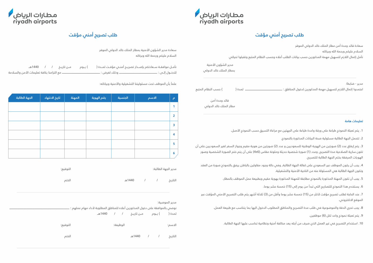
4948
طلب تصريح أمني مؤقت
سعادة مدير الشؤون األمنية بمطار الملك خالد الدولي الموقر
السالم عليكم ورحمة الله وبركاته
نأمــل موافقــة ســعادتكم بإصــدار تصريــح أمنــي مؤقــت لمــدة ( ) يــوم مــن تاريــخ / / 1440هــ
للدخــول إلــى : ــــــــــــــــــــــــــــــــــــــــــــــــــــــــــــــــــــــــــــــ وذلك لغرض : ــــــــــــــــــــــــــــــــــــــــــــــــــــــــــــــــــــــــــــــ مع التزامنا بكافة تعليمات األمن والسالمة
علمًا بأن الموظف تحت مسئوليتنا التشغيلية واألمنية وبياناته:
مدير الجهة الطالبة: التوقيع:
التاريخ / / 1440هـ الختم
مدير الموصية:
نوصي بالموافقة على دخول المذكورين أعاله للمناطق المطلوبة ألداء مهام عملهم : ـــــــــــــــــــــــــــــــــــــــــــــــــــــــــــــــــــــــــــــــــــــــــــــــــــــــــــــــــــــــــــ
لمدة ( ) يــوم مــن تاريــخ / / 1440هــ
االسم: الوظيفة: التوقيع:
التاريخ / / 1440هـ الختم
المهنة الجنسية االسم م
1
الجهة الطالبةتاريخ االنتهاءرقم الهوية
2
3
4
5
6
طلب تصريح أمني مؤقت
سعادة قائد وحدة أمن مطار الملك خالد الدولي الموقر
السالم عليكم ورحمة الله وبركاته
نأمل إكمال الالزم لتسهيل مهمة المذكورين حسب بيانات الطلب أعاله وحسب النظام المتبع وتقبلوا تحياتي
مدير الشؤون األمنية
بمطار الملك خالد الدولي
مدير - ضابط/
اعتمدوا إكمال الالزم لتسهيل مهمة المذكورين لدخول المناطق : ــــــــــــــــــــــــــــــــــــــــــــــــــــــــــــــــــــــــــــ لمدة ( ) حسب النظام المتبع
قائد وحدة أمن
مطار الملك خالد الدولي
تعليمات هامة
1. يتم تعبئة النموذج طباعة على ورقة واحدة طباعة على الجهتين مع مراعاة التسيق حسب النموذج األصل.
2. تتحمل الجهة الطالبة مسئولية صحة البيانات المذكورة بالنموذج.
3. يتم إرفاق عدد (2) صورتين من الهوية الوطنية للسعوديين و عدد (2) صورتين من هوية مقيم وجواز السفر لغير السعوديين على أن
تكون سارية الصالحية مدة التصريح, وعدد (1) صورة شخصية حديثة وملونة مقاس (4x6) على أن يتم ختم الصورة الشخصية وصور
الهويات المرفقة بختم الجهة الطالبة للتصريح.
4. يجب أن يكون الموظف عير السعودي على كفالة الجهة الطالبة, وفي حالة وجود مقاولين بالباطن يرفق بالنموذج صورة من العقد
وتكون الجهة الطالبة هي المسئولة عنه من الناحية األمنية والتشغيلية.
5. يجب أن تكون المهنة المذكورة بالنموذج مطابقة للمهنة المذكورة بهوية مقيم وبطبيعة عمل الموظف بالمطار.
6. يستخدم هذا النموذج للتصاريح التي تبدأ من يوم إلى (15) خمسة عشر يوما.
7. عند الحاجة لطلب تصريح مؤقت ألكثر من (15) خمسة عشر يوما وأقل من (3) ثالثة أشهر يتم طلب التصريح األمني المؤقت عبر
الموقع االلكتروني.
8. يجب تحري الدقة والموضوعية في طلب مدة التصريح والمناطق المطلوب الدخول اليها بما يتناسب مع طبيعة العمل.
9. يتم تعبئة نموذج واحد لكل (6) موظفين.
10. استخدام التصريح في غير العمل الذي صرف من أجله يعد مخالفة أمنية ونظامية تحاسب عليها الجهة الطالبة.

5150
Safety Additions to the fit-out guidelinesDesign Guidelines- Majority of the material used must be fire rated.
The following is mandatory for safety:1. Consider MOL Safety management system as required for tenant carrying work by 50 workers and above. (Attached MOL document)
2. Tenant shall assign personnel responsibility for safety and compliance.
3. Tenant shall conduct a safety induction to their employee and submit safety induction records to RAC SHE department.
4. Tenant shall issue a safety weekly report on regularly basis to RAC SHE department.
5. Tenant shall follow all general rquirements and guidelines for all having a work permit at the airport. (Attached RAC safety guidelines).
6. Tenant/ contractor shall provide weekly safety report and a corrective action plan.
Regulation for external projects:When working at a site with no available potable water, The stakeholder shall, where reasonably practicable, make accessible sufficient potable water for drinking and hand-cleaning that
(a) is close enough to the work area that neither drinking nor washing is inhinited;(b) is no further away than 200 m from the work place; and(c) meets the standards set out in the latest version of the Health safety standards.
(2) Where drinking water is not taken directly from a water pipe, the stakeholder shall ensure that it is kept in a container that is covered in an adequate manner.
Title: Procedures for ContractorsUndertaking Airside WorksResponsible Person: Chairman of KKIA Construction Committee
Reference: 5.8.5.001
Version No.: 1
1. Purpose of Procedure:To ensure that construction works do not adversely affect the safety of aircraft operations.
2. Purpose of Procedure:ICAO Annex 14, AerodromesICAO Pans Aerodromes (Doc 9981)
3. Introduction:Internationally, there have been many aviation accidents associated with construction works.In order ti assure the continued safe operations od aircraft at the aerodrome, it is essential that works are comducted and managed in a manner which will not impact on the safety of aircraft operations.
Date: 01/08/2016
Approved: 11/08/2016

5352
Title: Procedures for ContractorsUndertaking Airside Works
4. Procedure:4.1 It is the responsibility of the office of the Director General to assign a person to be responsible for developing and writing the procedure for contractors undertaking airside works.
4.2 The output from the pre-construction conference (Please refer to SOP 5.8.4.001) is used as a basis for developing procedures for contractors undertaking airside works.
4.3 Each mitigation measure that has been agreed as output from the pre-construction meeting is to be written into the procedures identifying
a. What is to be done
b. Who is to do it
c. Where is it to be done
d. When they are to do it
e. What equipment and materials, if any, are needed
4.4 The procedure also needs to cover the following generic elements
a. Who has overall responsibility for implementation of the procedure each time it is used?
b. Where do contruction team meet prior to entering the movement area?
c. Does the construction team need to be escorted to the works area?
d. What route is the construction team to take to the works area?
e. The requirement to make a list each day of vehicles, persons and equipment that will be going to the works area.
f. Do any runways, taxiways or apron areas need to be closed to facilitate the works?
g. If so, who will cordon off the works area and close the runway/ taxiway?
h. Are markers and lights needed to cordon off the works area and how will it be ensured that they are adequate separation between the works area and the aircraft?
i. How will it be ensured that the construction team do not interfere the radio navigation aids at the aerodrome?
j. How will the construction team communicate with ATC?
k. How will the works area be separated from air traffic?
l. Can the works continue during darkness and / or during low visibility operations?
m. If someone needs to leave the works area during the work period, how will they do this and how will they get back?
n. How will deliveries of large be made to the works area e.g concrete?
o. How will the FOD be managed at the works area?
p. How will it be ensured that no potential obstacles are brought into thr works area?
q. How will the construction team leave and clear the works are at the end of their work period.
r. Are there any special requirements to be implemented in the event of an aircraft accident or emergency at the aerodrome?
4.5 When the draft procedures are written they are to be sent to all stakeholders who have a role in the procedures and their comments are to be sought.
4.6 Any comments received will be reviewed and if appropriate incorporated into the procedures.
4.7 The Chair of the Construction Committee will be asked to approve the procedures.
4.8 When approved they will be submitted to GACA for regulatory approval.
4.9 Once regulatory approval had been recieved, the Chair of the Construction Committee will arrange for the procedures to be issued to the stakeholders and if necessary an AIP supplement will be prepared and promulgated.

5554
Access Control System Standard
General Requirements:A. The ACS shall be an enterprise class IP access control software solution. It shall be fully embedded within a Unified Security Platform (USP). The USP shall allow the seamless unification of the ACS with an IP video management system.
B. The ACS shall be highly scalable to support configurations consisting of thousands of doors with facilities spanning multiple geographic areas.
C. The ACS shall support an unrestricted number of logs and historical transactions (events and alarms) with the maximum allowed being limited by the amount of hard disk space available.
D. The ACS shall support a variety of access control functionalities, including but not limited to:
1. Controller (Unit) management, door management, elevator management, and area management.
2. Cardholder and cardholder group management, credential management, and access rule management.
3. Badge printing and template creation.
4. Visitor Management.
5. People counting, area presence tracking, and mustering.
6. Offering a framework for third party hardware integration such as cardand signature scanner.
E. The ACS shall support the following forms of authentication: Card Only, Card or Keypad (PIN), or Card and Keypad (PIN). It shall be possible to define a schedule for when Card Only or Card and Keypad authentication modes shall be required.
Software and Hardware Requirement:The Access Control System shall be:
1. Software: LENEL
2. Controller: Main: HID MERCURY EP1502
3. Sub-Controller: MERCURY MR52
4. VMS: MILESTONE XPROTECT SMART CLIENT
5. Card reader: HID
Access Control System Management:The ACS shall be based on an open architecture able to support multiple access control hardware manufacturers. The ACS shall be able to integrate with multiple non- proprietary interface modules and controllers, access readers, and other third-party applications.
The ACS shall be an IP enabled solution with all communication between the ACS and hardware controllers shall be based on standard TCP/IP protocol.
Software and Hardware Requirement:A. The ACS shall support integration with an IP Video Surveillance System (VMS). Integration with an IP video surveillance system shall permit the user to view live and recorded video.
B. Users shall be able to associate one or more video cameras to the following entity types: doors, elevator, and hardware zone (input points) and more.
C. The Monitoring UI shall present a true Unified Security Interface for access control and video surveillance. Advanced live video viewing and playback of archived video shall be available through the Monitoring UI.
D. It shall be possible to view video associated with access control events when viewing a report.
Access control Hardware specifications:The intelligent controller shall provide decision making, event reporting, and database storage for hardware platform. Two reader interfaces shall provide control for two doors and capable of supporting up to an additional 62 doors in paired and or alternate reader configurations with peripheral interface devices.
Main Panel:
A. Readers Ports: Two reader ports1. Unregulated pass through (150 mA maximum) or regulated 12Vdc2. Signaling 2-wire RS-485
B. Temperature: zero to seventy degrees Centigrade (0-70° C) operational, - 55 to 85 degrees Centigrade (-55 - 85° C) storage
C. Humidity: ten to ninety-five percent (10 - 95%) relative humidity, non- condensing (RHNC)
D. Standards:1. UL294 Recognized, CE Compliant, ROHS,2. FCC Part 15 Class A, NIST Certified Encryption
5756
E. Connectivity: 10/100 Ethernet, RS-232, Dial-up
F. Door Control:1. Two-reader ports: Clock and Data, Wiegand, or RS-4852. Eight programmable inputs, four relays, diagnostic LEDs
G. Access Control:
240,000 Cardholder capacity, 50,000 Transaction buffer, 32 Access Levels per cardholder, 19-digit (64-bit) user ID and 15-digit PIN numbers maximum, Activation and Deactivation dates, If/Then Macro capability
Sub-Panel:
The peripheral interface device shall provide a solution for interfacing to TTL/RS- 485 type readers and door hardware. The intelligent controller shall accept data from a reader with RS-485 signaling, provide a tri-stated LED control and buzzer control. It shall also provide six Form-C relay outputs and eight supervised inputs for monitoring. The controllershall communicate via a 2-wire RS-485 interface.
Reader:
A. The contactless smart card reader(s) shall be designed to securely read, interpret, and authenticate access control data from 13.56 MHz contactless smart cards:1. Multiple card format support by reader2. Elevator support3. Turnstile support4. Biometric device support5. OSPD protocol support6. Keypad support with programmable user commands, card input
B. The contactless smart card reader shall be fully compliant with Restriction ofHazardous Substances directive (RoHS) restricting the use of specific hazardous materials found in electrical and electronic products.
C. The contactless smart card reader shall comply with the following 13.56MHz- related standards to ensure product compatibility and predictability of performance:a. ISO 15693b. ISO 14443Ac. ISO 14443B
ICT Cabling StandardsContents
1.1 Cabling standard Guidelines
1.1.1 Telecommunication Backbone cabling infastructure system (Passive)1.1.2 Submittals1.1.3 Some basic passive requirements as per KKIA Cabling standards1.1.4 Cleaning1.1.5 Warranty
1.2 Inspection check list for project closure
1.3 Labeling
1.3.1 Fiber Optic Cable1.3.2 UTP Cable Label1.3.3 Cabinet, Fiber and UTP Patch panel1.3.4 UTP Mount Box1.3.5 Conjuction Mount Box on the EMT Piping1.3.6 Communication Cabinet1.3.7 Active Devices
1.4 Very Important Note

5958
1 Cabling StandardsExisting RAC-ICT infrastructure provides vast and secure connectivity and communication between various LAN Devices and equipment for RAC Systems and Network Services across various facilities.
1.1 Cabling standard Guidelines1.1.1 Telecommunication Backbone cabling infrastructure system (PASSIVE)
1. Contractor to follow RAC Airport cabling standards for the installation of the Optical Fiber Optic Cables, UTP Cat 6/6A, Coaxial cables, cable connecting hardware equipment’s, Communication Cabinets, patch panels, ODF, cabling identification products, labeling, reports, documentation.
2. Contactor to provide details specifications of Products for UTP, Fiber and Copper. Also to include datasheets, design, termination identifiers details, termination details, splicing details, patching details with proper labeling, Fluke test reports, Outlet and Port Data Sheet with Documentation. ICT shall review the product details with documents supported and samples for proper approval.
3. Contractor shall provide all the Specifications for all the Telecommunication Backbone cabling components and accessories, with prior approvals. No change of any material during the project and end of the project as per requirement in detail package.
4. Contactor shall submit Test FLUKE Report and commissioning for UTP and Fiber Optic Cables.
5. Contractor shall provide Training and Handover ON SITE and OFF-SITE Knowledge transfers.
1.1.2 Submittals:
Contractor shall supply:
1. Schedule of proposed installation, installation methodology, installation standards and implementation, incudes dates and milestone and update weekly and monthly.
2. Overall system design (pre-design and approved design approvals for cable layouts) with product and material approved datasheets, backbone cabling system plant layout, Fluke test Reports, Data Sheets, OSP Cabling Plant details, and detail drawings (FIBER and UTP).
3. Manpower details with their roles and specialization, certified in specific roles, experienced and capable team with project references.
4. Equipment’s and Tools associated for the project work, specialized and technical staff with experience.
5. Contractor and their support staff commitment to follow the rules and procedures during the work.
1.1.3 Some basic passive requirements as per KKIA Cabling standards:
1.1.3.1 Shop Drawings:
1. For each type of cable tray. (New cable tray and existing cable tray)
2. Show fabrication and installation details of cable tray, including plans, elevations, and sections of components and attachments to other construction elements.
3. Designate components and accessories, including clamps, brackets, hanger rods, splice-plate
4. connectors, expansion-joint assemblies, straight lengths, and fittings.
1.1.3.1.1 Coordination Drawings:
1. Floor plans and sections, drawn to scale. Include scaled cable tray
2. layout and relationships between components and adjacent structural, electrical, and mechanical elements.
Show the following:i. Vertical and horizontal offsets and transitions.ii. Clearances for access above and to side of cable trays.iii. Vertical elevation of cable trays above the floor or bottom of ceiling structure.
1.1.3.1.2 Concealed, Exterior Installations:
a. Cable trays and associated accessories designed for exterior use shall be heavy duty steel, complying with BS6157 and BS 6946 powder coated with UV resistant epoxy/polyester to post-galvanized steel.
b. The base material of post-galvanized steel shall confirm the requirements of to EN 10142:1991 and EN 10143:1993
c. Cable Trays, base materials, Fittings, and Accessories: all bends, T connections width reduction parts etc. shall be by the same manufacturer as the cable tray.
d. The coating shall be even, durable and scratch resistant.
e. Earth continuity shall be ensured by providing corrosion resistant straps or by use of shake-proof star washers

6160
1.1.3.1.3 CABLE TRAY ACCESSORIES
a. Fittings: Tees, crosses, risers, elbows, and other fittings as indicated, of same materials and finishes as cable tray.
b. Covers: Louvered, type of same materials and finishes as cable tray.
c. Barrier Strips: Same materials and finishes as cable tray.
d. Cable tray supports and connectors, including earthing continuity straps, as recommended
e. by cable tray manufacturer.
f. Earth continuity straps shall be fitted at all cable tray joints.
1.1.3.1.4 CABLE TRAY AND LADDERS INSTALLATION
1. Comply with recommendations in EN 61537, the manufacturer and the SBC Wiring Regulations. Install as a complete system, including all necessary fasteners, hold-down clips, splice-plate support systems, barrier strips, hinged horizontal and vertical splice plates, elbows, reducers, tees, and crosses.
2. Remove burrs and sharp edges from cable trays fit plastic end caps on support channel ends.
3. Fasten cable tray supports to building structure.a. Place supports so that spans do not exceed maximum spans allowed by codes and standards, and manufacturers recommendations. Supports shall be arranged to ensure that the maximum deflection of the fully loaded tray does not exceed 1/360 of the span length. Supports shall additionally be placed at either side of bends or intersections and at all changes of direction.
b. Construct supports from channel members, threaded rods, and other appurtenances furnished by cable tray manufacturer. Supports shall be manufactured from the same materials as the cable tray unless otherwise indicated. Cable trays supported on hangers shall have additional lateral supports. Arrange supports in trapeze or wall bracket form as required by application.
4. Make connections to equipment with flanged fittings fastened to cable tray and to equipment.
5. Support cable tray independent of fittings. Do not carry weight of cable tray on equipment enclosure.
6. Install expansion connectors where cable tray crosses building expansion joint and in cable tray runs that exceeddimensions recommended in the relevant standards. Space connectors and set gaps per applicable standard.
7. Make changes in direction and elevation using standard fittings.
8. Make cable tray connections using standard fittings.
9. Sleeves for Future Cables: Install capped sleeves for future cables through fire stop-sealed cable tray penetrations of fire and smoke barriers.
10. Workspace: Install cable trays with enough space to permit access for installing cables.
11. Install barriers to separate cables of different systems, such as power, communications, and data processing; or of different insulation levels, such as 230/400. In general, separate cable tray systems are to be provided.
12. After installation of cable trays is completed, install warning signs in visible locations on or near cable trays.
13. Where cable trays receive minor damage during the construction works the galvanized surfaces shall be repaired by applying zinc rich epoxy primer – applied in accordance with the manufacturer’s instructions.
14. Cutting of cable trays shall be along a plain line of material and shall not be made along the line of the perforations in the cable tray.
15. Joining of tray or ladder shall be carried out in accordance with the manufacturer’s instructions but generally as follows:a. Nuts, bolts, washers and other fastenings shall be of compatible materials.b. Bolts shall be of the domed headed type installed with nuts facing away from cables.c. All holes in cable trays shall be provided with a suitable male and female bush for cable exit.d. Where cable trays are broken to enable cables to pass through walls proprietary sleeves shall be installed to facilitate installation and later withdrawal. Where cables pass through fire rated walls/floors sleeves shall be galvanized steel.
16. Where walls are non-fire rated sleeves shall be Heavy gage P.V.C. Sleeves shall have a minimum diameter of 25mm larger than the cable or bunch of cables passing through them.
17. Sleeves passing through walls or floors shall extend for 50mm either side of the penetration.
18. All holes through fire rated elements shall be sealed using proprietary products to ensure that the original fire integrity of the element is maintained. Where holes pass through external walls additional sealing shall be provided using flexible rubber boot or shroud over sleeve projection.
19. For horizontal runs of cable trays /ladder trays, provide minimum 250 mm clear space from top and onside of tray, to facilitate cable installation.
20. Where cable trays / ladders carrying power cables and conductors cross cable trays for communication systems, provide minimum 150 mm clear space between the top of the lower tray and bottom of the upper tray.

6362
1.1.3.1.5 CABLE INSTALLATION
a. Install cables only when cable tray installation has been completed and inspected.
b. Install cables only when EMT Piping with proper support and approved material installation has been completed and inspected.
c. Filling rate will be %56 as per NFPA70 National Electrical Code.
d. EMT Piping not to hold any support from existing piping or clamps, needs to build, install proper support and fixing with safety and regulations for future removals and troubleshooting’s.
e. Fasten cables on horizontal runs with cable clamps or cable ties as recommended detailed elsewhere in this specification. Tighten clamps only enough to secure the cable, without indenting the cable jacket. Install cable ties with a tool that includes an automatic pressure limiting device.
f. On vertical runs, fasten cables using proprietary chips / cleats to tray every 450mm.
g. Cable ties are not permitted. Install intermediate supports when cable weight exceeds the load carrying
h. capacity of the tray rungs.
i. Install covers after installation of cable is completed.
j. For single cabling/wiring, EMT Piping with Airport cabling standard to be followed, pre-approvals are required for piping, use of materials.
1.1.3.1.6 Material /Product overviews
a. All the materials and products for the project shall be approved by KKIA priory to procurement and implementation.
b. Passive components must have valid support and availability in the market.
c. Product vendor support agreement is essential and mandatory for future availability and support.
1.1.3.1.7 Single Mode Fiber Optic Cable
a. SM optical fiber glass shall be manufactured from ultra-pure synthetic silica glass. SM manufactures from natural quartz will not be accepted.
b. Outdoor cable must be industry standard Armored, protected with additional layer.
c. Cable must be approved by ICT.
d. Fiber terminations must be approved by ICT.
1.1.3.1.8 MATERIALS FINISHES
a. Cable Trays, Fittings, and Accessories: Steel, complying with EN6157 support components
b. Cable Trays, Fittings, and Accessories: all bends, T connections, width reduction parts etc. shall be by the same manufacturer as the cable tray.
c. All cable trays and associated components shall be hot dip galvanized to EN ISO 1461 after manufacture with minimum 60-micron thickness. Cable tray up to 3000 mm long will be 1,5 mm thickness, longer than 3000 mm will be 2 mm thickness and 2 mm thickness for all cable ladders.
d. Cable trays carrying main and sub main feeder cables shall be heavy gage return flange. All other cable trays may be medium gage as appropriate.
e. In very limited cases site fabrication is allowed.
f. EMT Piping to be with complete labeling at each conjunction box, on the pipe, on the cable.
g. USE OF PERMANT LABELS and Marks only allowed.
h. Labels to be marked in the attached and submitted drawings.
1.1.4 CLEANING
a. All the area shall NEAT & CLEAN all the times.
b. The contractor shall provide everything necessary for the proper protection of materials and completed works.
c. The contractor shall maintain and remove on completion all coverings, materials etc., used for protection and safety.
d. Damages directly or indirectly caused to road carriageways, footpaths, walls, floor etc., regardless of their existing conditions, shall be reinstated / repaired by the contractor at its own expense to the satisfaction of the client.
e. All surplus material shall be removed and the site shall be CLEAN and NEAT immediately after reinstatement work is completed.

6564
1.1.5 WARRANTY
a. Unless otherwise stated in this specification section all Active Materials and components parts shall be guaranteed against defect, damage, or non-conformity for a period of (3) years.
b. During the guarantee period, the manufacturer shall make all necessary repairs or replacement to achieve conformity to the requirements of the Contract Documents.
c. Passive Cabling, terminations, splicing, joints for Cat6/Cat6A/Fiber Multimode/Fiber Single Mode shall have warranty of at least 15years from the product and contractor to support for any issues pertaining to it during these periods with availability of their manpower and material to fix it.
1.2 INSPECTION CHEC KLIST FOR PROJECT CLOSURE
1. Check with submitted Layout drawings, routes and path as marked with location details for FIBER and UTP as per RFP and BOQ.
2. In excel Sheet, mark each FIBER and UTP to be inspected and checked.
3. Contractor must prepare the check list and handover to us for inspection in details.
4. FIBER and UTP shall be enclosed in EMT PIPE Conduits with labels.
5. FIBER and UTP cable shall be in separate EMT Pipes.
6. EMT Pipes for FIBER and UTP Cables shall be layout in proper way with good support and fix with ceiling and brackets to avoid any fall and outrage.
7. If any civil work or drilling work, need to be closed and inspected with engineering department.
8. Labelling at each conjunction box and EMT Pipe approx. distance of 10-15mts for FIBER and UTP Cables.
9. UTP and FIBER shall not be exposed or without EMT PIPE COVER under the ceilings and inside the offices. (ALL AREA)
1.3 LABELING1.3.1 FIBER OPTIC CABLE
On the FIBER CABLE and on the EMT PIPE (with Pen Marked and Label sticker) “RAC-ICT FIBER CABLE FROM BN.FL.RN.CN.FPP TO BN.FL.RN.CN.FPP”
1.3.2 UTP CABLE Label
On the UTP Cable and on the EMT PIPE (with Pen Marked and Label sticker)“RAC-ICT UTP CABLE FROM FL.RN TO FL.RN”
1.3.3 Cabinet, Fiber and UTP Patch panel
1.3.3.1 FIBER TERMINATION DETAILS
i. No. of cores terminated (FLUKE REPORTS)ii. Spare Core detailsiii. Active Core detailsiv. Non-Terminated Cores
1.3.3.2 UTP Cable Terminations
i. Labeling inside and outside the Patch panel ports, matching with end pointsii. Labeling on the UTP Patch cables both sides
1.3.4 UTP Mount Box
RAC-ICT.FL.RN.CN.UPP. DN.FL.: Floor LevelRN.: Room NumberCN.: Rack Cabinet Row NumberUPP.: Patch Panel NumberDN.: Switch Data Port Number
1.3.5 Conjunction Mount Box on the EMT Piping
RAC-ICT.BN.FL.RN.CN.FPP.BN.: Building NameFL.: Floor LevelRN.: Room NumberCN.: Rack Cabinet Row NumberFPP.: Fiber Patch Panel NumberFCT.: Fiber Cores and TYPE
1.3.6 COMMUNICATION CABINET
RAC-ICT DATA CABINET (CN.)CONNECTED WITH RAC-ICT FIBER CABLE FROM BN.FL.RN.CN.FPP TO BN.FL.RN.CN.FPP

6766
1.3.7 ACTIVE DEVICES
a. Labeling on the ACTIVE Devices
b. Labeling on the UPLINK PORTS corresponding to the Switch and Patch panel ports.
1.4 VERY IMPORTANT NOTE:
a. USE OF FLEXIBLE PVC and FLEXIBLE EMT CONDUIT are not allowed and not permitted.
b. USE OF EXISITNG PIPE, TRAY needs prior approval with design document submittal, depends on approval and availability only. Contractor to build and install new cable tray, EMT PIPE as per standards.
c. NEW PIPES INSTALLED to be 30% Volume to be FREE SPACE.
d. Power injectors, HUB, Converter for FIBER and UTP are not allowed and not permitted.
e. FIBER SPLICING / FIBER JOINTs if any to be approved before start of cable pulling with approval and justification support without any loss of signal and performance. Contractor will be 100% responsible for the Fiber Splicing and Joints for period of 25 Years.
ALL THE MENTIONED STANDARDS AND SPECIFICAITONS WILL BE DULY AGREED AND WILL BE FOLLOWED DURING THE PROJECT WORK AND COMMITTED.
Contractor Name: ____________________________________________________
Authorized Representative Signature: __________________________________
Dated: ____________________________
Fire Detection and Alarm System StandardFire Detection and Alarm System Requirements:
The Fire Alarm System (FAS) is a very important system which can save the lives of people and protect properties by sensing smoke, thermal rise and flame with appropriate action to the suppression system of water, foam or dry chemicals.
The FAS reports to the Control & Monitoring System for events gathering, recording and display in the workstation of Main Fire Station at AB5 and other locations within 3-seconds. The FAS is interfaced with the HVAC system, security access control, elevators, escalators and moving walkways when applicable.
The individual Fire Control Panels (FCPs) or Fire Annunciator Panels (FAPs) in the buildings also sound alarms, evacuation sound through public address (future), bells or lights in addition to showing which zone is in alarm.
At King Khaled International Airport (KKIA) in order to complete any FAS project RAC ICT department requires all contractors during any modification\renovation\construction of an area to follow the below list:
1. The fire control panel must be NOTIFIER NFS 320 (or better) for small single zone facility and NOTIFIER NFS 640 (or better) for larger multi zones facility, UL listed and FM approved.
2. Wherever there is area (such as data center) which must be protected by suppression system such as gas or water, the fire extinguishing control panel must be NOTIFIER RP-2002(E) (or better).
3. Pre-approval to items required must be obtained before installation from ICT department.
4. All field devices such as smoke, heat, manual pull, duct detector, UV detectors, etc. must be addressable.
5. All interfaces to other major equipment must be met, such as: Elevators, HVAC, Travellators, Emergency doors, E-gates, etc.
6. Interface to the main public address.
7. All wiring must be flame retardant 18AWG concealed inside EMT conduit inside buildings and rigid steel conduit in exposed open areas.
8. All wires must be clearly labelled with the same identification at both ends (device and at the panel). Hence if a termination junction (JTR) is being used in between due to the length of the cable between the device and the panel the same identification must be used (i.e. if the label at the device was FD12345, then the same number must be at the other ends (JTR & Panel)).
6968
9. Complete drawing must be submitted which should show the following:
a. Complete panel drawing identifying every labelled wire connected to it.
b. Block diagram of the panel identifying the modules inside.
c. Complete area drawing identifying every device location.
d. Riser diagram (block diagram) which identifies the levels of the area being covered and routing.
e. List of all devices installed in the area which includes the following:
1. Type of device.
2. Brand name.
3. Model number.
4. Possible substitute.
10. Labeling of the conduits for identification.
11. List of terminated and any spare labelled wires with device identification in that area.
12. List of all IP addresses for the panel if applicable.
13. Interface the new panel to the main fire station shall be hardware and software ready including fire dedicated fiber optic link as well as Bacnet/IP protocol card with open API.
14. All facility shall have interactive firefighters’ display indicating all fire zone locations, installed at the entrance of the facility to serve as a guide for fire department to reach the activated zone / device at the earliest.
To commission the system, all the above must be met accordingly otherwise RAC ICT department will not approve the project.
Public Address System StandardsPublic Address System Requirements:
A public address system (PA system) is an electronic system comprising microphones, amplifiers, loudspeakers, and related equipment. It increases the apparent volume of a human voice or other acoustic sound source or recorded sound. PA systems are used in any public venue that requires an announcer, performer, etc. be sufficiently audible at a distance or over a large area. Typical applications include public transportation such as airport and facilities, and live or recorded information venues. A PA system may include multiple microphones or other sound sources, a mixing console to combine and modify multiple sources, and multiple amplifiers and loudspeakers for louder volume or wider distribution.
Simple PA systems are often used in small venues such as hangers, mosques, etc. PA systems with many speakers are widely used to make announcements in public, institutional and commercial buildings and locations—such as airports and passenger vessels and aircraft. PA and Intercom systems are commonly used as part of an emergency communication system.
The Public Address System (PAS) is a very important system which can save the lives of people and protect properties by broadcasting the information to the public about any major disaster or fire taking place in such areas.The PAS must be interfaced to the FAS (Fire Alarm System) in order to report to the public about any fire is taking place in a particular area.
At King Khaled International Airport (KKIA) in order to complete any project which has PAS RAC ICT department requires all contractors during any modification\renovation\construction of an area to follow the below list:
1. The PAS must be interfaced with the existing system at KKIA.
2. The PAS must be interfaced with the fire system for voice evacuation.
3. Must meet EN54-16 fire regulations.
4. Pre-approval to items required must be obtained before installation from ICT department.
5. All field devices such as speakers, etc. must be addressable.
6. All wiring must be flame retardant concealed inside EMT conduit inside buildings and rigid steel conduit in exposed open areas.
7. All wires must be clearly labelled with the same identification at both ends (device and at the panel).
7170
8. Complete drawing must be submitted which should show the following:
a. Complete panel drawing identifying every labelled wire connected to it.
b. Block diagram of the panel identifying the modules inside.
c. Complete area drawing identifying every device location.
d. Riser diagram (block diagram) which identifies the levels of the area being covered and routing.
e. List of all devices installed in the area which includes the following:
1. Type of device.
2. Brand name
3. Model number.
4. Possible substitute.
9. Labeling of the conduits for identification.
10. List of terminated and any spare labelled wires with device identification in that area.
11. List of all IP addresses for the panel if applicable.
12. Interface the new system to main KKIA system shall be hardware and software ready including PAS dedicated fiber optic link as well as Bacnet/IP protocol card with open API.
To commission the system, all the above must be met accordingly otherwise RAC ICT department will not approve the project.
New Office Network StandardsRAC-ICT Network InfastructurePrepared by ICT Networks
Contents:1. Purpose 2. Objective3. Network drops Location for New Office Design4. Communication5. Active and Passive Components requirements and Specifications6. Review and Approvals

7372
1. Purpose
This document is developed by RAC -ICT- Infrastructure (Networks) to define the Scope of Work for Riyadh Airport’s Network Infrastructure Standards and readiness for any New Office/Counters Design and Re-locations.The purpose of this document is to ensure that all new offices/Counters area have Network ports with the connectivity to the existing RAC-ICT Network with System and its Services comply with ICT Network Standards.
2. Objective
The Objective defined for the Scope of Work is to provision and build the Network with Standard Cabling, design and build ICT Communication Room with Active and Passive Components. These will provide the vast levels of connectivity, high availability, integrated security, flexibility, availability and resiliency and enhance manageability to congregate the converged network services.
3. Network drops Location for New Office DesignNetwork drop and Power outlet installation must incorporate with
• high standards of material/components with functionality and flexibility with longer lifetime 20-25years.
• Outlets to be easy to access within 1mts to 2mts reachability.
• High quality finishing with no cable exposures, fully covered as per office environmentstandards and matchings.
• Built-in data, power and USB ports such aso built-in Desk Outletso Multi plug outlets for Workstations
New Office location’s network drops and Power Outlet with below mentioned quantity to be installed by provisioning and considering high quality of standard installations, easy to access and presentable way.
a. Two (2) Network drops and Two (2) Power Outlet for
i. Each office desks / Countersii. Each Workstations Areaiii. the Projector, Meeting table at the Meeting Rooms.iv. Centralized location for Printer
b. Two (2) Network drops, each at the centre of the office area, at the corridor and at the ceiling / Wall with 3mts – 4mts spare cable for future expansions, to be installed by considering heatmaps with 99.9% signal and coverage for
i. Wireless Access Pointsii. CCTV Camerasiii. Finger print devices
According to the required number of the network drops as per New Office Design layout, network drop must be installed by the contractor comply with ICT Cabling standards.
4. Communication Room Standards & Specifications:New Communication Room must be designed and build with Communication Standard Specs as mentioned below with back bone connectivity to their respective distribution points as mentioned:
• Cooling (19C-24C)• SMART UPS• Dual Electrical Power Source and• Standard 42U Communication Cabinet 800*1000.• Biometric and CCTV access
• Backbone Fiber Connectivity to the Distribution Point.
o For the Access Layer Buildings AC1, AFx, FK1, TC1, UW4, KKCF - the Fiber Distribution and Distribution Switch(PE) is located at Airport Administration Building (AC1-GF-Main Data Center-Network Room R243)
o For the Access Layer Buildings AC2, AM2, AM1, UV1, AB2, AB3, AB6, AL1 - the Fiber Distribution and Distribution Switch(PE) is located at Airport Security Building (AC-2F-Secondary Data Center-Network Room R203)
o For the Access Layer Buildings Passenger Terminals T1 & T2 All the Levels, Royal Terminal (TK1) - the Fiber Distribution and Distribution Switch(PE) is located at Passenger Terminal Building TL2 Arrivals R2730 & TL1 Service Level R1980.
o For the Access Layer Buildings Terminal T5, LC3, LC5, AOCC, AARF(AB5), Tunnel - the Fiber Distribution and Distribution Switch(PE) is located at Terminal Building Datacenter DC1 at Basement Level and Datacenter DC2 at Arrival Level.
5. Active and Passive Components requirements and Specifications
The following below active and passive network components must be provided by the contractor for the new office design network and cabling:

7574
SNo Qty CommunicationRoomActive and Passive Component Description
Cisco catalyst series WS-C3850-48PS Gigabit Switch 48 Ports, FULL POE 750WAC, IP Base Image, Power Stack, Dual Power supply, Stack module and cables; (includes all accessories, Power Cord UK Standard, USB Console Cable, Smart Net Cisco TAC Support) with 3years support, Installation and warranty.
Cable 6A Cable Layout/Pull as per standard design and approved cable path, route and location with installation of EMT Pipe / New Communica-tion Cable Tray fully covered and protected.Includes Cable Terminations, Cable Labels, Fluke test results.Comply with Airport cabling standards document and Section #3 standards. Submit Built-in layout engineering drawings with cable route and cable path, Termination matrix details. (Preferred SYSTIMAX or AT&T UTP)
UTP CAT6A Patch Panel with built in snap in modular 24 ports with complete accessories includes universal guide, installation and terminations as per industry standards. (Systimax or AT&T)
Cisco Network Module C3850-NM-4-10G. (Support Warranty)
1
2
Cisco SFP-10G-LR (single Mode Fiber)3
Cisco SFP-1G-GLC (single Mode Fiber)4
5
Cisco SFP-1G-GLC (single Mode Fiber)6
UTP industry standard Patch cord cable 3mts (SYSTIMAX or AT&T)7
UTP industry standard Patch cord cable 5mts (SYSTIMAX or AT&T)8
9
Standard Communication Cabinet 42U, 800*1000, fully ventilated doors, 8 Outlets UK Power PDU extension (4), Cabinet FANs, Cabinet Cable Tray with complete accessories, Black Color with lock. Ground Mounted with proper support and installation. (CommScope or AT&T)
10
CCTV Camera high resolution with type, specs and model to be selected as per heat map and coverage.Cameras licenses to be with existing Genetec Security Center Version 5.7. and archive server and storage.Refer to CCTV Standard Document.
15
New Communication Room to be built with Communication Standard Specs as such Stable Power, Cooling (19C-24C); SMART UPS (Item #11); RAISED FLOOR; FIRE RATED WALLS, Dual Electrical Power Source for the communi-cation cabinets, Biometric and CCTV access for the communication room, cable containment and cable tray on the ceiling for UTP cables and Backbone Fiber Connectivity to the Distribution Point, labeling. Follow Section #4.
16
17
24 Cores Single Mode Fiber Cable, Layout/Pull with EMT Conduit, Cable route and path with installation of new EMT Pipe or new cable tray to distribution points as mentioned in point #4.. Follow and Comply with Airport cabling standards.Submit Built-in layout engineering drawings with cable route and cable path, Fluke Test Reports, Fiber cable plant design with core details.(SYSTIMAX or AT&T)
11
Fiber Patch Panel with full terminations for three (3) Single Mode 24 Core Fiber cables with complete accessories includes universal guide. (SYSTIMAX or AT&T)
12
Cisco Wireless Access Point AIR-AP3802I-E-K9 with Licenses for Cisco Prime, Cisco ISE and CISCO WLC CONTROLLER 5520.Refer to the Wi-Fi Standard Document.
14
Single Mode Fiber Patch cables industry standard duplex tested LC-LC 1mt only. (SYSTIMAX or AT&T)
During construction/renovation, unused existing network utp cables to be removed if available from the existing communication cabinet completely.
13
6. Review and Approvals
• New Office design with Network drop locations has to be submitted for review and approved by ICT before start of the project.
• For Cabling Standards, Refer to the ICT Cabling Standards Document.
• For Network Architecture and Network Standards, Refer to the ICT Network Design and NetworkStandards Document.
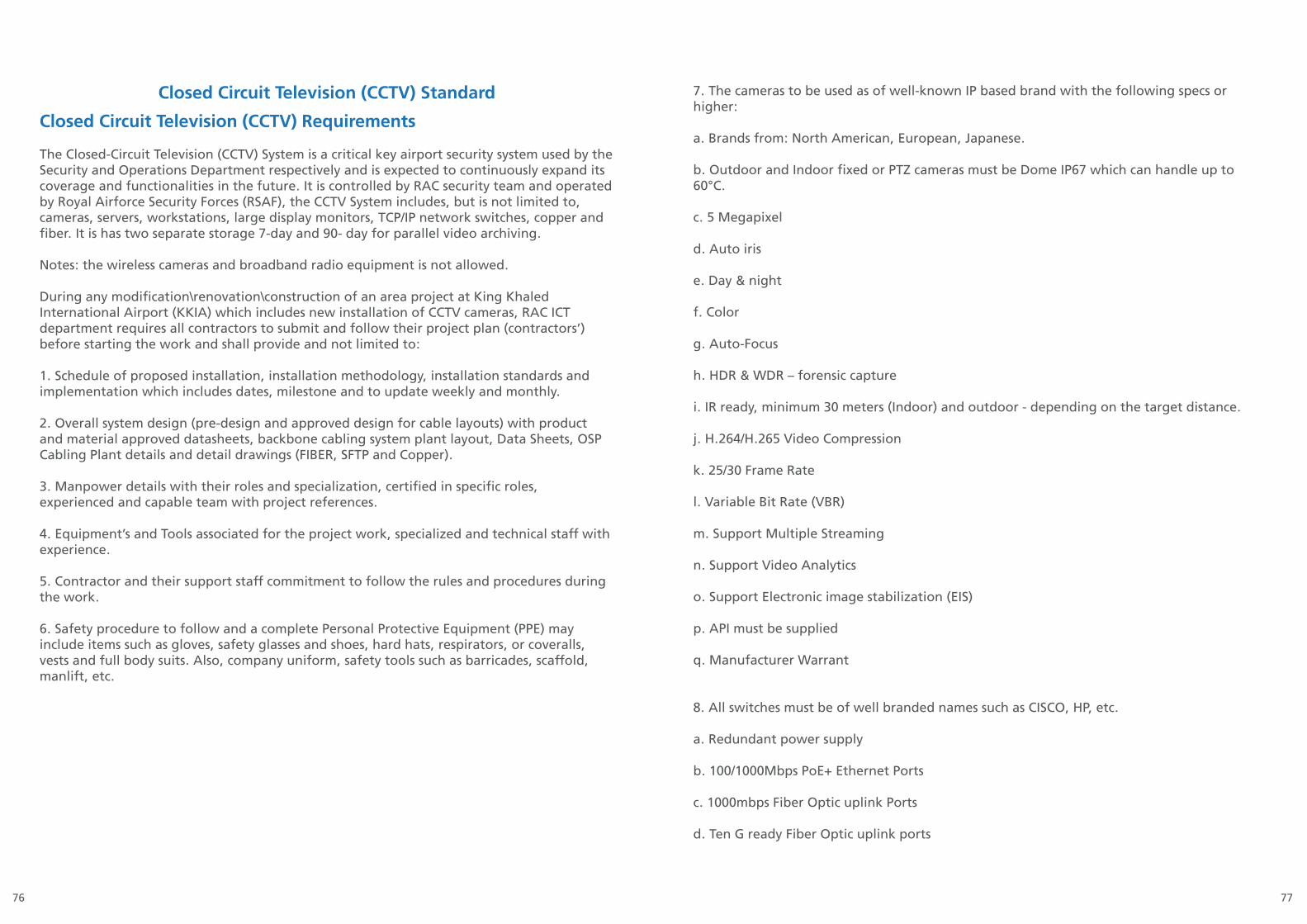
7776
Closed Circuit Television (CCTV) StandardClosed Circuit Television (CCTV) Requirements
The Closed-Circuit Television (CCTV) System is a critical key airport security system used by the Security and Operations Department respectively and is expected to continuously expand its coverage and functionalities in the future. It is controlled by RAC security team and operated by Royal Airforce Security Forces (RSAF), the CCTV System includes, but is not limited to, cameras, servers, workstations, large display monitors, TCP/IP network switches, copper and fiber. It is has two separate storage 7-day and 90- day for parallel video archiving.
Notes: the wireless cameras and broadband radio equipment is not allowed.
During any modification\renovation\construction of an area project at King Khaled International Airport (KKIA) which includes new installation of CCTV cameras, RAC ICT department requires all contractors to submit and follow their project plan (contractors’) before starting the work and shall provide and not limited to:
1. Schedule of proposed installation, installation methodology, installation standards and implementation which includes dates, milestone and to update weekly and monthly.
2. Overall system design (pre-design and approved design for cable layouts) with product and material approved datasheets, backbone cabling system plant layout, Data Sheets, OSP Cabling Plant details and detail drawings (FIBER, SFTP and Copper).
3. Manpower details with their roles and specialization, certified in specific roles, experienced and capable team with project references.
4. Equipment’s and Tools associated for the project work, specialized and technical staff with experience.
5. Contractor and their support staff commitment to follow the rules and procedures during the work.
6. Safety procedure to follow and a complete Personal Protective Equipment (PPE) may include items such as gloves, safety glasses and shoes, hard hats, respirators, or coveralls, vests and full body suits. Also, company uniform, safety tools such as barricades, scaffold, manlift, etc.
7. The cameras to be used as of well-known IP based brand with the following specs or higher:
a. Brands from: North American, European, Japanese.
b. Outdoor and Indoor fixed or PTZ cameras must be Dome IP67 which can handle up to60°C.
c. 5 Megapixel
d. Auto iris
e. Day & night
f. Color
g. Auto-Focus
h. HDR & WDR – forensic capture
i. IR ready, minimum 30 meters (Indoor) and outdoor - depending on the target distance.
j. H.264/H.265 Video Compression
k. 25/30 Frame Rate
l. Variable Bit Rate (VBR)
m. Support Multiple Streaming
n. Support Video Analytics
o. Support Electronic image stabilization (EIS)
p. API must be supplied
q. Manufacturer Warrant
8. All switches must be of well branded names such as CISCO, HP, etc.
a. Redundant power supply
b. 100/1000Mbps PoE+ Ethernet Ports
c. 1000mbps Fiber Optic uplink Ports
d. Ten G ready Fiber Optic uplink ports

7978
e. Layer 3 ready
f. Stackable (if required)
g.Manufacturer Warranty
9. Pre-approval to items is required and must be obtained before installation from ICT department.
10. A sample unit per items or devices must be tested in RAC-ICT Laboratory for fully operability and compatibility prior to deployment.
11. SFTP Cat 6A or Fiber optic (Armored-Type) cables concealed inside EMT conduit inside buildings and rigid steel conduit in exposed open areas. Proper labeling on the conduits to identify easily.
12. Check with submitted Layout & As-Built drawings for routes and path as marked with location details for FIBER, SFTP and Copper as per RFP and BOQ.
13. In excel Sheet, mark each FIBER, SFTP and Copper to be inspected and checked.
14. Contractor must prepare the checklist and handover to ICT department for inspection indetails.
15. EMT\Rigid Steel Pipes for FIBER and SFTP Cables shall be laid out in proper way with good support and fix with ceiling and brackets to avoid any fall and outrage.
16. Any civil or drilling work must be closed and inspected with engineering department.
17. Labeling at each junction box and EMT\Rigid Steel Pipe approx. distance of 10-15 meters for FIBER, SFTP and Copper Cables.
18. FIBER, SFTP and Copper shall not be exposed or without EMT\Rigid Steel PIPE COVER under the ceilings and inside the offices (ALL AREA).
19. If the fiber is spliced a fluke test report must be provided
20. Passive Cabling, terminations, splicing, joints for Cat6A/Fiber Multimode/Fiber Single Mode shall have warranty of at least 15 years from the product and contractor to support for any issues pertaining to it during these periods with availability of their manpower and material to fix it.
21. Contactor shall submit Test FLUKE Report and commissioning for SFTP and Fiber Optic Cables.
22. All cables must be clearly labeled with the same identification at both ends (device and at the panel).
22. All cables must be clearly labeled with the same identification at both ends (device and at the panel).
23. Cabinets must be installed properly as per standard for easy access and should not obstruct other Cabinets in the Communication/Electrical Rooms.
24. Power: Circuit Breaker termination and properly labeled in the panel.
25. Complete drawing must be submitted which should show the following:
a. Completecabinetdrawingidentifyingeverylabeledwireconnectedtoit.
b. Block diagram of the cabinet identifying the modules inside.
c. Completeareadrawingidentifyingeverydevicelocation.
d. Riser diagram (block diagram) which identifies the levels of the area being covered androuting.
26. List of all devices installed in the area which includes the following:
a. Type of devices
b. Brand Name
c. Model number
d. Possible substitute
27. Labeling the conduits for identification.
28. List of terminated and any spare labelled wires with device identification in that area.
29. List of all IP and MAC addresses for the system if applicable.
30. Interface the new cameras to the main CCTV system, it shall be hardware and software ready including new CCTV dedicated fiber optic link as well as BACnet/IP protocol card with open API.
31. Upgrade the capacity of the 90-day storage system if needed as per KKIA requirements
32. Safety procedure must be followed at all times otherwise work will be stopped.
33. Contractor must provide Operation and Maintenance (O & M) Manual.
34. Support contract shall be included and not limited to maintenance hardware and software system.
35. Full training to RAC maintenance staff during the warranty period.
36. List of spare parts required.

8180
37. In-Line UPS – for at least one hour back up time, all active components especially LAN Switches must have redundant (second) power source from different Circuit Breaker Panel/Main Transformer.
To commission the system, all the above must be met accordingly otherwise RAC ICT department will not approve the project.
Building Automation System StandardGeneral Requirements:
To standardize communications between building automation devices from different manufacturers at KKIA, we will be using BACnet protocol for BAS because it allows for interoperability of devices and systems from various vendors by allowing data to be shared and equipment to work together easily. The design for Building Control Systems and Integration solutions shall have the following criteria:
Sustainable Design
LEED Certification Solutions
Systems Integration Capabilities
Energy Management Solutions
Open System Architecture
Scalable Building Solutions
The system reliability helps maintain ideal comfort conditions and the remote monitoring and diagnostics help ensure that problems are fixed before they grow. If we are to connect one building or an entire enterprise the BMS design shall include the following:
Units to be Controlled or Monitored:HVAC System:
Chiller Plant with cooling towersAir Handling UnitsFAN Coil Units PumpsVariable Air Volume Plumbing Systems: Submersible Pumps Jockey Pumps
Units to be Controlled or Monitored:Electrical System:
MDBsEscalatorsElevatorsTransformersUPSGeneratorsLighting Control System

8382
Platform Support:Supported Operating Systems:
Win8 64 bitWin 2012 64-bitMinimum required OS configurations: Client Workstation: 64bit w/ 4GB RAM Host Workstation: 64bit w/ 8GB RAM
BAS Standard:
The latest edition of the following standards and codes in effect and amended as of supplier’s proposal date, and any applicable subsections thereof, shall govern design and selection of equipment and material supplied:
1. American Society of Heating, Refrigerating and Air Conditioning Engineers (ASHRAE).
2. ANSI/ASHRAE Standard 135-2008, BACnet.
3. Uniform Building Code (UBC), including local amendments.
4. UL 916 Underwriters Laboratories Standard for Energy Management Equipment.
5. National Electrical Code (NEC).
6. FCC Part 15, Subpart J, Class A.
7. EMC Directive 89/336/EEC (European CE Mark).
8. UL-864 UUKL listing for Smoke Controls for any equipment used in smoke controlsequences.
Drawings:The system supplier shall submit engineered drawings, control sequence, and bill of materials for approval.
1. Drawings shall be submitted in the following standard sizes: 11” x 17” (ANSI B).2. Eight complete sets (copies) of submittal drawings shall be provided.3. Drawings shall be available on CD-ROM.
System Documentation:
Include the following in submittal package:
1. System configuration diagrams in simplified block format.
2. All input/output object listings and an alarm point summary listing.
3. Electrical drawings that show all system internal and external connection points, terminalblock layouts, and terminal identification.
4. Complete bill of materials, valve schedule and damper schedule.
5. Manufacturer’s instructions and drawings for installation, maintenance, and operation of all purchased items.
6. Overall system operation and maintenance instructions—including preventive maintenance and troubleshooting instructions.
7. For all system elements—operator’s workstation(s), building controller(s), application controllers, routers, and repeaters—provide BACnet Protocol Implementation Conformance Statements (PICS) as per ANSI/ASHRAE Standard 135-2001.
8. Provide complete description and documentation of any proprietary (non-BACnet) services and/or objects used in the system.
9. A list of all functions available and a sample of function block programming that shall be part of delivered system.
Operator Activity Log:1. An Operator Activity Log that tracks all operator changes and activities. System shall track what is changed in the system, who performed this change, date and time of system activity, and value of the change before and after operator activity.
2. Operator shall be able to display all activity, sort the changes by user and by operation.
3. Operator shall be able to print the Operator Activity Log display.
4. Operator Activity log shall be accessible via the Web Client for viewing, sorting, filtering,and Printing.
8584
Technology to be used:
1. Lighting Control: ASCENTMICROSET 4
2. Field Controllers: ALERTON VLC 651R, VLC660R, VLC550, VLC1188, VLC 853, VLC16160, VLC1600, VAV SD, VAV SD2A, VAVIH-SD, VAV-DD, VAV-DD7, VLD-362.
3. Protocol: BACNET MS/TP
4. Software Platform: Compass
ICT NetworkDesign and Standards Overview
Prepared by: ICT Networks TeamPurpose
This document is developed by RAC -ICT- Infrastructure (Networks) to brief about ICT Networks for King Khaled International Airport (KKIA) Design and Standards. The purpose of this document, to clear understand the new project’s requirement and their design to incorporate with the existing RAC-ICT Network to meet the future requirements and comply with ICT Standards.
Objective
The Objective defined is to build and supply active and passive network for any project with current design and standards that provides the vast levels of connectivity, high availability, integrated security, flexibility, availability and resiliency and enhance manageability to congregate the converged network services.
This includes Data Center Setup, Network Application, IP based Voice and Video, IP based special systems (Fire Alarm System, Low Voltage Systems), Wireless Access and other future demanding applications requirement of the Riyadh Airports.
Business Continuity Plan
To minimize the services downtime and maximize the recovery operation in the event of system disaster, following below must be complied and followed:
• To provide system redundancy and load balancing
• To provide link redundancy.
• To provide data backup solution.
• Availability of spare hardware component.
• Availability of resources (Staff reach ability).
• Quarterly, Semi- annually and annually exercises and drills.
• Smart Net support for all the Active Hardware

8786
EnterpriseCampusNetworkModule
Serv
erFa
rmN
etw
ork
Infr
astu
ctur
e
Infrastructure Design
Server
Distribution
Core
Distribution
Edge Case - 1
Edge Case - 2
Wan
Network Management
1 2
1 2
1 2
Edge Switch
Server
Edge Switch
Router
NMS
ICT ARCHITECTURAL DIAGRAMICT Infrastructure Logical Diagram
Description:
• Core to Distribution connectivity is 40/20/10GB• Edge to Core connectivity is 1/10 GB (Aggregation)• Edge to Distribution connectivity is 1/10 GB (Aggregation)• Server to Distribution connectivity is 1/10/20 GB (Aggregation)• Client to Edge connectivity is 1000 Mbps (Gigabit)
RAC-ICT Enterprise Composite Network
The enterprise campus network is categorized as follows:
• Network Infrastructure o Core Level
o Distribution Levelo Edge / Access Level
Core Level
The Core Layer provides wire – speed, scalable, intelligent LAN Switching and non-blocking devices typically implemented at the main data center linking distribution, server farm and access layer switches.
Features
• Gigabit Technology• Support 10/20/40 GB bandwidth backbone connectivity
• Provide L2 & L3 load balancing
• Support L4 filtering
• Redundant hardware & connectivity
• Advance QoS / ToS function :
o Multiple priority queues with minimum of 4
o Rate limiting, multilayer traffic classification and prioritization
• Support 802.1D, 802.1w, 802.1s, 802.1Q, 802.3ad, 802.1x, 802.1p, IP v6, AVVID, MPLS,DHCP relay feature and minimum OSPF routing protocol
• Advanced security features
• Scalable architecture
• Multilayered switching capabilities
Performance• Local switching on blades
• High performance non blocking switch
• Capable to support Gigabit Ethernet GBIC/SFP/MTRJ ports
• Capable to support 10/100/1000 Ethernet Ports
• Capable to support 10/20/40 Gigabit interface

8988
Hardware • Rack Mounted; Modular Ethernet Switch with minimum of 4 slots
• Hot Swappable Blades, interfaces, Power Supply and Fan Tray
• Redundant hardware & connectivity for continuous operation
• Power Supply: Minimum of 2 units
• Modular Configuration Switching Fabric / Engine
• Appropriate point for PoE Ethernet Support
• Input power supply: Auto volt 110-220 Vac
• Complete Accessories upon delivery
Management
• Management Function: Web interface management, Command line interface / SSL and SNMP compatibility, Supports RMON: Minimum of Alarm, Events, History and Statistics
Distribution Level
The Distribution Layer provides higher bandwidth backbone connectivity to aggregate multiple wiring closets and or aggregation groups with greater segmentation across the campus and connectivity for distributed fileservers. Scalable, secured intelligent LAN switching and non-blocking device connecting between Core layer and or access layer switches.
Feature• Gigabit Technology
• Support 10/20/40 GB bandwidth backbone connectivity
• Provide L2 & L3 load balancing
• Support L4 filtering
• Redundant hardware & connectivity
• High bandwidth backbone connectivity
• Advance QoS / ToS function :
o Multiple priority queues with minimum of 4
o Rate limiting, multilayer traffic classification and prioritization
• Support 802.1D, 802.1w, 802.1s, 802.1Q, 802.3ad, 802.1p, IP v6, AVVID andRouting protocol if required on the proposed design : minimum OSPF routing protocol
• Support Stackability feature
• Advanced security features
• Scalable architecture
• Multilayered switching capabilities
Performance • Local switching on blades• High performance non blocking switch• Capable to support Gigabit Ethernet GBIC/SFP/MTRJ ports• Capable to support 10/100/1000 Ethernet Ports• Capable to support 10/20/40 Gigabit interface
Hardware
• Rack Mounted; Fixed or Modular Ethernet Switch configuration• Hot Swappable interfaces, Power Supply and Fan Tray• Redundant hardware & connectivity for continuous operation• Power Supply: Minimum of 2 units• Modular Configuration Switching Fabric / Engine• Appropriate point for PoE Ethernet Support• Input power supply : Auto volt 110-220 Vac• Complete Accessories upon delivery
Management
• Management Function: Web interface management, Command line interface / SSL and SNMP compatibility
• Supports RMON: Minimum of Alarm, Events, History and Statistics
Edge LevelThe Edge or Access level Switch to provide users with high speed and secured network connectivity.

9190
Feature
• Gigabit Technology• Provide L2 Load balancing• Support L4 filtering• Redundant hardware & connectivity• High bandwidth backbone connectivity• Supports Quality of Service and Prioritization:o Multiple priority queues with minimum of 4o Multilayer traffic classificationo Prioritization of 4 queues per port IEEE 802.1p QoS function and protocol blocking o Rate limiting capabilities for bandwidth allocation• Support 802.1D, 802.1w, 802.1s, 802.1Q, 802.1ad, 802.1x, 802.1p, IP v6, AVVID• Support Stackability feature• Advanced security features
Hardware • Rack Mounted; Fixed configuration or modular Ethernet switches: o Typically Layer 2 or Advance Layer 2• Interface : Minimum of 24 10/100/1000B-TX Ethernet Ports• Interface : Supports minimum of two Gigabit Ethernet SFP/GBIC/MTRJ Ports• Performance: minimum 8.8 Gbps forwarding bandwidth, minimum 6.6 million packets persecond wire speed performance, and support with minimum 8,000 MAC addresses• Supply with PoE as required• Redundant power supply capability• Input power supply: Auto volt 110-220 Vac
Management
• Management Function: Web interface management, Command line interface / SSL and SNMP compatibility
Availability & Requirements
• Redundant Link & Hardware.• Provide compatible, ICT recommended and Approved hardware for Core, Distribution andAccess Layer Hardware with its components in full.• Provide Spare Hardware and Components.• Provide additional spare line modules, supervisor engine cards as per existing compatiblehardware with license and installation, configurations.• Provide SMART and Manageable Uninterruptible Power Supply in each cabinet:o Rack mountable.o Must supply power for at least 30 minutes at full load for access layer.o Must supply power for at least 4 hours at full load for core/ Distribution/Server layer.o Must protect against spikes, surges and power sag.o Include all necessary hardware and software for use with SNMP. Minimally system mustsend an alarm to the network management system when power fails. Must work with the network management system.
Warranty and Conditions• Provide during the technical offero Provide detailed Technical Training plano Logical and physical diagram for every option proposed o Detailed project plan• All Hardware must have 3 years warranty with valid SMARTNET TAC SUPPORT• Cisco Prime and Cisco ISE License for active hardware to be provided.• Spare unit for each hardware/component• All hardware must have the latest, tested and reliable firmware version & upgrade contract• System installation & specification should comply with ICT and Airport Standards

9392
Documentation
• Provide system configuration documentation & diagram after project completion• Provide documentation and reference information documenting compliance with therequirements
Management
• Management Function: Web interface management, Command line interface / SSL and SNMP compatibility• Supports RMON: Minimum of Alarm, Events, History and Statistics
Training• Provide Authorized Professional Technical Training with Certifications from the OEM (Original Equipment Manufacturer ) for all the Hardware and Software products delivered for a minimum of five(5) qualified ICT Personnel’s from RAC-ICT.
Refer to ICT Cabling standards documents to comply with the mentioned guidelines and procedures.

94


![Heritage Property Management - Home · An owner has the obligation to evict a tenant if they [tenant(s)] continually refuse to comply with the Association "rules and regulations."](https://static.fdocuments.in/doc/165x107/6017f38d07bfdb573b5c2752/heritage-property-management-an-owner-has-the-obligation-to-evict-a-tenant-if.jpg)